
382280 - Uncategorized Extech - Free user manual and instructions
Find the device manual for free 382280 Extech in PDF.


| Product Type | Programmable DC Power Supply, 200 Watt |
| Model | Extech 382280 |
| Adjustable Voltage Output | 0.000 to 40.000 VDC |
| Adjustable Current Output | 0.000 to 5.000 ADC |
| Fixed Outputs | 5 VDC / 2 A and 3.3 VDC / 3 A |
| Voltage Resolution | 1 mV |
| Current Resolution | 1 mA |
| Voltage Accuracy (Programmed) | 0.05% ± 9 mV |
| Current Accuracy (Programmed) | 0.2% ± 9 mA |
| Ripple and Noise (0-40V, 0-5A) | < 3 mVrms (CV), < 3 mArms (CC) |
| Response Time | < 150 ms |
| Load Regulation | < 1 mV / A |
| Memory Locations | 200 (000 to 199) |
| Over-Voltage Protection (OVP) | Programmable, 0.001 to 40 V |
| Over-Current Protection (OCP) | Enable/disable, threshold 0.05 A, delay up to 600 s |
| Automatic Test Sequencing (ATS) | Step duration 1-60 s, continuous cycling available |
| Display | Backlit dot matrix, 2-line |
| Remote Control | RS-232 interface, baud rate 9600 |
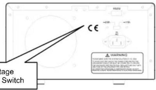
| Power Source | 110/220 VAC, 50/60 Hz, selectable via rear switch |
| Dimensions (W x H x D) | 310 x 135 x 250 mm (12.2 x 5.3 x 9.9 in) |
| Weight | 3.8 kg (8.4 lbs) |
| Safety Features | Earth ground terminal, OVP, OCP, short-circuit protection, standby mode |
| Operating Environment | Indoor use, ensure 5 cm (2 in) ventilation clearance |
| Cleaning | Disconnect power, wipe with dry cloth; do not use abrasives |
| Accessories Included | RS-232 cable, power cord, user manual |
Frequently Asked Questions - 382280 Extech
User questions about 382280 Extech
0 question about this device. Answer the ones you know or ask your own.
Ask a new question about this device
Download the instructions for your Uncategorized in PDF format for free! Find your manual 382280 - Extech and take your electronic device back in hand. On this page are published all the documents necessary for the use of your device. 382280 by Extech.
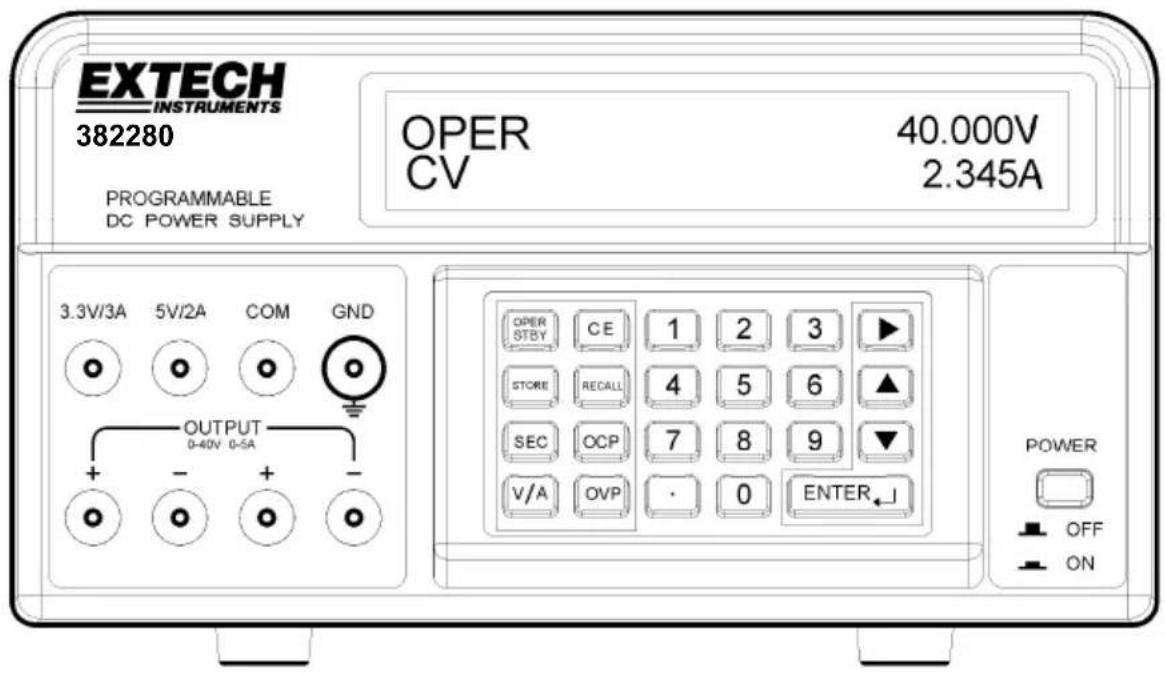
USER MANUAL 382280 Extech
Programmable DC Power Supply
200 Watt (40 Volts / 5 Amps)
Model 382280
Introduction
Congratulations on your purchase of the Extech 382280 Programmable DC Power Supply. This 200 watt power supply offers an adjustable 5ADC / 40VDC output plus fixed outputs (5VDC and 3.3VDC). Programming features include custom over-voltage/current protection with delay timer, 199-test storage, and automated testing. Careful use of this power supply will provide years of reliable service.
Safety Symbols

WARNING
Please read the statement thoroughly to prevent injury or loss of life, and to prevent damage to this product.

Earth Ground Terminal
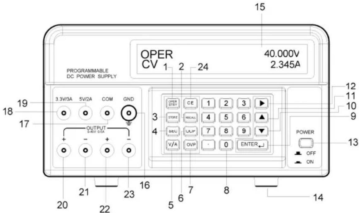
- OPER/STBY: Operation/Standby button. Press to enable/disable the output. When the supply is in the STANDBY mode the output is 0 volts.
- RECALL: Press to call up stored output sets or to activate Automatic Test Sequencing.
- STORE: Press to save the present V/A output set to memory. Use the numeric keys (not the arrows) to select a storage location from 000 to 199 and then press ENTER.
- SEC (Seconds): Press to enter time in seconds. Use the ENTER key to confirm entries.
- V/A: Press to toggle between voltage (V) and current (A) on the display.
- OCP (Over-Current Protection): Press to enable/disable OCP.
- OVP (Over Voltage Protection): Press to program the OVP value (defaults to 40V).
- Numeric keypad and period button.
- ENTER: Press to confirm entries.
- ▼ (DOWN Arrow): Press to decrease a programming value.
- ▲ (UP Arrow): Press to increase a programming value.
- ▶ (RIGHT Arrow): Press to move the cursor to a new location in a row.
- POWER ON/OFF: Press to turn the supply on or off.
- Rubber feet.
- Dot matrix display.
- GND: Ground terminal (connected to the chassis of the unit).
- COM: Common terminal for the 5V and the 3.3V output.
- 3.3V/3A: Positive terminal for the 3.3V output. If more than 3A is drawn, the output will be lower than the 3.3V specified.
- 5V/2A: Positive terminal for the 5V output. If more than 2A is drawn, the output will be lower than the 5V specified.
- Positive Terminal for the 40VDC / 5ADC output. This terminal is physically connected to terminal 22. Use terminal 21 (not COM) as the negative terminal for best accuracy. Note that terminal 21, 23, and COM are connected.
- Negative terminal for 40VDC / 5ADC (terminal 20) output.
- Positive Terminal for the 40VDC / 5ADC output. This terminal is physically connected to terminal 20. Use terminal 23 (not COM) as the negative terminal for best accuracy.
- Negative terminal for 40VDC / 5ADC (terminal 22) output.
- CE (Cancel Entry): Press to cancel a programming entry.
Preparation for use
- Place the supply on a flat level surface.
- Select the input voltage using the switch on the rear of the supply (see diagram above).
- Make sure the sides and the back of the unit are not blocked. Leave at least 2" (5 cm) of space for good ventilation.
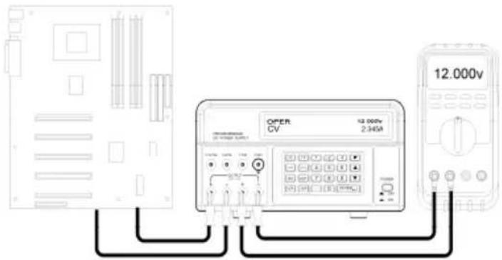
Basic Test Setup Diagram
Setting and Outputting Voltage and Current
NOTE: The 3.3V and 5V fixed outputs are always active when power is turned on.
NOTE: The power supply enters the STBY (stand-by) mode when the power is turned on. The output values, time delay, and OVP are the same as they were before the power was turned off.
- Connect the power supply output to the circuit or device under test before pressing the OPER/STBY button.
- Check that the displayed voltage and current output settings are as desired.
-
To change the values of voltage or current use the V/A button to move the underline cursor to first digit of the voltage or current display, enter the value directly from the numeric keypad and then press ENTER or:
a. Move the underline cursor to voltage or current with the V/A button,
b. Use the RIGHT arrow button to select the digit to change,
c. Use the UP/DOWN arrow buttons to change the digit value
d. Press the ENTER button to select the value. -
To clear any programming entries, press the CE button.
-
Press the STBY/OPER button to enable the power supply output.
Note: If the output goes to zero, the current or voltage limit may be set too low.
-
To change the output values during operation, use the RIGHT & UP/DOWN buttons.
-
The user can monitor the output voltage by connecting a DMM as shown above.
Warning: When the unit is placed in STBY mode, the output is 0V; however the output terminals are still physically connected to the internal circuit.
Over Voltage Protection (OVP)
Over Voltage Protection (OVP) allows the user to set a maximum permissible output voltage If the voltage limit is exceeded, the unit will display “OVP” and revert to the STBY mode.
Note: The OVP is always active. To be able to set the output voltage to 40V, you must set the OVP to 40V.
Setting the Over Voltage Protection (OVP) value
- In the STBY mode, press the OVP key, “?_” appears in the display.
- Enter a value from the keypad (range of 0.001 to 40V).
- Press the ENTER key to store the value.
Viewing the Over Voltage Protection (OVP) value
The OVP value can be viewed when the supply is switched from the OPER mode to the STBY mode. When switched, “OVP” will briefly appear in the upper display line and the value will briefly appear in the middle of the lower line of the display.
Over Current Protection (OCP)
Over Current Protection (OCP) allows the user to set a maximum permissible current. If the current limit is exceeded, the unit automatically reverts to the STBY mode.
Setting the Over Current Protection (OCP) value
- In the STBY mode, press the V/A key to move the underline cursor to the A display.
- Press the OCP key and enter the value from the keypad (0.05 to 5A)
- Press the ENTER key to store the value.
Note: The threshold for OCP is 0.05A.
Enabling the Over Current Protection (OCP)
Press the OCP button to enable/disable the OCP function. "OCP" will appear in the display when the function is enabled.
Over Current Protection (OCP) Time Delay
The OCP shutdown can be delayed up to 600 seconds using the SEC function.
- Press the SEC key. “?” will appear in the display.
- Enter the value from the keypad (0.01 to 600 seconds) and press the ENTER key.
Storing Test Setups
- Set the Voltage and Current values as desired.
- Press the SEC button and set the time in seconds (1 to 600 seconds). This time will be associated with this step. You need to set the time for each step.
Note: The user should set SEC at a minimum of 1 second for the Auto-Step function. If Auto-Step and OCP are enabled at the same time, the value of SEC will be used for the Auto-Step function, while the time duration for OCP will be fixed at 0.01 seconds.
-
Press the STORE button to save the values. "STRxxx?" will appear in the display (where "xxx" (000 to 199) will be the memory location).
-
Press ENTER to store the value in the displayed location or enter a new location number from the keypad and press ENTER. If a three digit number is entered, pressing ENTER is not necessary.
Recalling Test Setups
- Press the RECALL button to view the setup in a memory location. "RCLxxx" and the stored values will appear in the display (where "xxx" (000 to 199) will be the memory location).
- To view the setup in any other location, enter the setup number and press ENTER. If a three digit number is entered, pressing ENTER is not necessary.
- Press RECALL to exit the display.
Automatic Test Sequencing (ATS)
In ATS mode, the unit automatically cycles through a series of stored test setups. The first and last steps are programmable and the sequence will include all steps between the first and last steps. Each test setup memory location represents one step. The duration the step is programmable from 1 to 60 seconds and is programmed when the steps are stored.
Note: Initial setup and sequencing should be performed in the STBY mode to verify proper operation without an active output.
Setup and Operation of Automatic Test Sequencing (ATS)
- To set the LAST and FIRST step of the sequence:
a. Press the RECALL button.
b. Use the numeric keypad to enter the three digit test setup location number for the last step (RCL018, for example) and press ENTER.
c. Use the numeric keypad to enter the three digit test setup location number for the first step (RCL001, for example) and press ENTER.
d. Press RECALL
- The time duration for each step is stored with each step in the storing process.
- To begin the test sequencing, press and hold the RECALL until the beeper sounds and the stair-step icon appears. The sequencing will automatically begin a single cycle through the programmed steps.
- Observe the output for proper operation.
- Press the OPER/STBY key to activate the output
- Press the OPER/STBY to return to the standby mode or press CE to exit the sequencing mode
Note: The ATS session will be terminated if any command is received via the RS-232c interface.
Note: For continuous cycling, hold the RECALL button while turning power on.
RS-232 data format
Baud rate 9600
Parity none
Data bits 8
Stop bits 1
Flow control none
RS-232 Connection
Connect the supplied communications cable to the rear of the power supply and to the communications port of the PC.
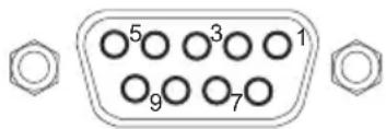
Power Supply PC
Pin 2 Pin 2 RX
Pin 3 Pin 3 TX
Pin 4 Pin 4 DTR
Pin 5 Pin 5 GND
RS-232 Commands
The command format is as follows: Command Parameter
For example: V 20.5 (sets output to 20.5VDC)
An ASCII code for
Summary of Commands
STBY
OPER
V xx.xxx
A x.xxx
SEC xxx.xx
OVP xx.xxx
OCP 0
OCP 1
STORE xxx
RECALL xxx
STEP
?
V?
A?
OCP?
OVP?
SEC?
STATUS?
Note: All commands are case insensitive.
Example of an RS-232C Program
V 20.5
A 1.25
V 30 A 2 SEC 20
OVP 35
SEC 60
OCP 0
OCP 1
STORE 120
RECALL 100
RECALL 110
Step
statement) and the ending step is 110 (recalled after step 100).
?
V 40.000 40.000 CV
A 01.000 00.999 CV
OCP 10.00 ENABLE
OVP 40.000
5V OK 3.3V OK
OPER CV
V?
V 40.000 40.000 CV
A?
A 01.000 00.999 CV
Note: The first set of data following the character V or A is the programmed value, while the second set of data is the read back A/D value. The third set of data is the status (CV, CC) of the unit. If the third set of data shows 0V, the unit is placed in the STBY mode. The unit sends out a
Using Windows ^TM Terminal or HyperTerminal program for PC Communication
The Terminal or the HyperTerminal program is included in all Windows ^TM operating systems. Typically it is located using the following path:
START Menu > Programs > Accessories > Communications > Terminal or HyperTerminal
When in the Terminal or HyperTerminal program, go to PROPERTIES and configure as follows:
- In the CONNECT TO field, select COM1 or COM2 (depending on which port is being used).
- In the CONFIGURATION section, select the following data format: Baud rate 9600, no parity, 8 data bits, 1 stop bit, and no flow control.
- In the ASCII SETUP section, click on "echo typed characters" and "Send line ends with line feeds".
After Terminal or HyperTerminal is setup, type in the commands as described in the previous examples.
Programmed Voltage and Current (after 5-minute warm-up)
| Range | Resolution | Accuracy | |
| Voltage V (C.V.) | 0 to 40V 1mV 0.05% | ± 9mV | |
| Current A (C.C.) | 0 to 5A 1mA 0.2% ± | 9mA |
Voltage and Current Display (Read back)
| Range | Resolution | Accuracy | |
| Voltage V (C.C.) 0.1 | to 40V 1mV 0.1% ± 12mV | ||
| Current A (C.V.) 0.05 | to 5A 1mA 0.2% ± 12mA |
Display Backlit Dot Matrix (2-line) Display
Programmable Voltage Output 0.000 to 40.000VDC
Programmable Current Output 0.000 to 5.000ADC
Resolution 1mV; 1mA
Fixed Outputs 5V (2A) and 3.3V (3A)
Memory 200 locations
Accuracy Adjustable Voltage: 0.05% ±9mV
Adjustable Current: 0.2% ±9mA
Fixed 5V: ±0.25V; Fixed 3.3V: ±0.16V
Response Time < 150 ms
Temperature Coefficient < 100ppm / °C
Load Regulation < 1mV / Amp
Line Regulation No effect if line voltage is within 90V and 130V for 115V power (200V to 240V for 220V power).
Ripple and Noise (0 40V,0 5A) < 3mV rms(C.V.) < 3mA_rms (C.C.)
(5V/2A, 3.3V/3A) 10mV rms \~ 20mVrms
Open Circuit (OCP) detection Current > 0.05A
C.V. or C.C. detection Current > 0.05A
Short Circuit Protect When the 5V or 3.3V output is less than 1V (shorted), one of the preceding alert symbols will be shown on the LCD
Power Source 110/220VAC 50/60Hz
Dimensions 310 x 250 x 135mm (12.2 x 9.9 x 5.3")
Weight 3.8kg (8.4 lbs)
- Programmable DC Power Supply
- Model 382280
- Introduction
- Safety Symbols
- Preparation for use
- Basic Test Setup Diagram
- Setting and Outputting Voltage and Current
- Over Voltage Protection (OVP)
- Setting the Over Voltage Protection (OVP) value
- Viewing the Over Voltage Protection (OVP) value
- Over Current Protection (OCP)
- Setting the Over Current Protection (OCP) value
- Enabling the Over Current Protection (OCP)
- Over Current Protection (OCP) Time Delay
- Storing Test Setups
- Recalling Test Setups
- Automatic Test Sequencing (ATS)
- Setup and Operation of Automatic Test Sequencing (ATS)
- RS-232 data format
- RS-232 Connection
- RS-232 Commands
- Summary of Commands
- Example of an RS-232C Program
- Using Windows TM Terminal or HyperTerminal program for PC Communication
Brand : Extech
Model : 382280
Category : Uncategorized