
DM-550 - Wall mount Gabor - Free user manual and instructions
Find the device manual for free DM-550 Gabor in PDF.


| Product Type | Single Arm Desktop Wall Mount |
| Brand | Gabor |
| Model | DM-550 |
| Compatible Monitor Size | 17 to 32 inches (43.2 to 81.3 cm) |
| Maximum Weight Capacity | 19.8 lb (9 kg) |
| VESA Compatible Patterns | 75x75 mm, 100x100 mm |
| Tilt Adjustment | ±40° |
| Rotation Adjustment | ±90° |
| Monitor Arm Swivel | ±180° (can be limited to ±90°) |
| Base Arm Pivot | ±90° / ±180° |
| Height Adjustment Range | 6.9 to 17.1 inches (17.5 to 43.5 cm) |
| Mounting Options | Clamp (edge) and Grommet (non-edge) |
| Maximum Desktop Thickness | 3.1 inches (8 cm) for clamp |
| Material | Aluminum |
| Product Weight (without monitor) | 5.2 lb (2.35 kg) |
| Package Weight | 6.7 lb (3.03 kg) |
| Package Dimensions (HxWxD) | 4 x 16.75 x 10 inches (10.2 x 42.5 x 25.4 cm) |
| Arm Tension Adjustment | Yes, via spring tension screw |
| Cable Management | Yes, top and bottom cable guides |
| Warranty | 1-year limited warranty |
| Recommended Cleaning | Soft, dry cloth only |
Frequently Asked Questions - DM-550 Gabor
User questions about DM-550 Gabor
0 question about this device. Answer the ones you know or ask your own.
Ask a new question about this device
Download the instructions for your Wall mount in PDF format for free! Find your manual DM-550 - Gabor and take your electronic device back in hand. On this page are published all the documents necessary for the use of your device. DM-550 by Gabor.
USER MANUAL DM-550 Gabor
for 17 to 32 in. Desktop Computer Monitors

User Manual
Thank you for choosing Gabor.
The Gabor Single Arm Desktop Mount can securely support a monitor from 17 to 32 inches. The stylish yet rugged aluminum build will hold a monitor weighing up to 19.8 pounds, and the adjustable spring tension mechanism makes it easy to move your monitor to the perfect viewing height. The mount gives you maximum control over swivel, tilt, and rotation, precise monitor placement, and optimum viewing angles.
The articulating arm has adjustable spring tension that ensures monitor stability. The included VESA plate accommodates monitors with 75×75 and 100×100 VESA patterns, and it features an integrated lock to ensure monitor safety when adjusting screen height. A heavy-duty, low-profile clamp and base will fit into any space with tight clearance, like a cubicle. For mid-desk attachment, the stand includes mounting hardware for grammet installation.

Safety Warnings
- Please read and follow the instructions, and keep this manual in a safe place.
- To avoid damage to this product, be careful not to overtighten or improperly thread any of the threaded fittings.
- Clean this product with only a soft, dry cloth.
- Make sure that this product is intact and that there are no missing parts.
- Mounting surfaces should be sturdy and flat. Do not install this product on a weak, uneven surface.
-
Make sure everything is secure before proceeding to the next step.
-
Do not exceed the maximum load capacity.
- Do not install this product on an unsteady structure or one that is prone to vibration, has a chance of being impacted, or is susceptible to other movements. Reinforce the structure as necessary before instelling this product.
- If you have safety concerns about installing this product, contact a qualified professional or installation contractor.
- If this product is missing hardware or there are defective parts, visit www.madebygobar.com or call Customer Service at 212 594-2353.
- All images are for illustrative purposes only.
Product Specifications
Monitor display size
17 to 32 in. (43.2 to 81.3 cm)
Maximum weight per monitor
19.8 lb. (9 kg)
Maximum desktop thickness
3.1 in. (8 cm)
VESA standards
75×75mm
100×100 mm
Monitor orientation
±180°
Monitor tilt
±40°
Monitor rotation
±90°
Monitor arm swivel
±180°
Base arm pivot
±90°/±180°
Arm height adjustment
6.9 to 17.1 in. (17.5 to 43.5 cm)
Weight without monitors
5.2 lb. (2.35 kg)
Package weight
6.7 lb. (3.03 kg)
Package dimensions (H × W × D)
4×16.75×10 in. (10.2×42.5×25.4 cm)

Overview

GABOR
Parts Included
| M-A 4xM4×12 mm screws | M-B 4xM5×12 mm screws | M-C 4xDS washers |
| A 1XMonitor arm | B 1XBase arm | C 1XVEPA plate | D 1XClamp | E 1XLange | F 1XBase | G 1XNotch cover | H 1XCamping flange |
| I 1XCorriage bolt | J 3XFlot hex screws | K 1XWasher | L 1XHex nut | M 2XPlastic cao | N 1X4 mm hex key | O 1X5 mm hex key | P 1XWrench |
| A 1XMonitor arm | B 1XBase arm | C 1XVEPA plate | D 1XClamp | E 1XLange | F 1XBase | G 1XNotch cover | H 1XCamping flange |
| I 1XCorriage bolt | J 3XFlot hex screws | K 1XWasher | L 1XHex nut | M 2XPlastic cao | N 1X4 mm hex key | O 1X5 mm hex key | P 1XWrench |
Clamp Installation
- Attach the flange (E) to the base (F) with the three hex screws (J). Tighten them with hex key (N) until secure.

- Fit the flange behind the desk. You may need to remove the flange bolts if the space between the desk and wall is too tight.
-
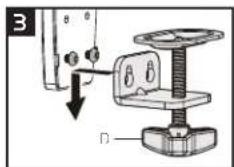
Before you attach the clamp to the flange, measure the thickness of the table or desktop.
-
If the desktop is 0.4 to 2 inches thick, screw the flange bolts into the top holes.
- If the desktop is 2 to 3.3 inches thick, remove the flange bolts from the top holes, and screw them into the bottom holes.
To attach the clamp to the flange, fit the wide end of the clamp holes over the flange bolts, and press down on the clamp so it securely sits on the flange bolts.


Important! The clamp should rest on the flange bolts. If the clamp is not parallel to the bottom of the base, loosen the flange bolts until the clamp rests entirely on them.
- Tighten the flange bolts with hex key [N] until secure.
- With the flange flush against the edge of the desktop, tighten the clamp locking knob until the base is secured to the desktop.

Grommet (Non-edge) Installation
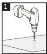
Important! Predrilled holes in the desktop should be between of 0.4 to 2.4 inches (10 to 60 mm) in diameter.
- If you need to drill a hole in the desktop, use a 3/8-inch or 10 mm drill bit.
- Attach the notch cover (G) to the bottom of the base with the flat hex screws (J). Make sure the flat side of the cover is even with the edge of the base.
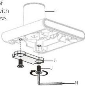
- Cover the hex screws with the plastic caps (M).
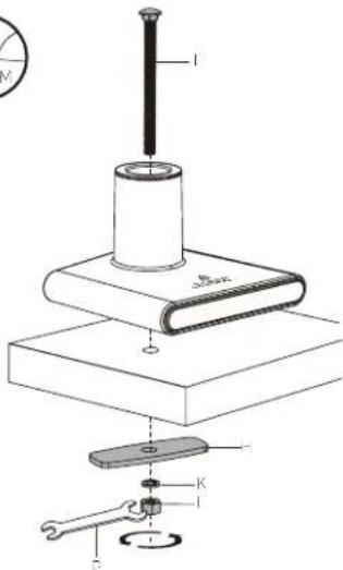
- Ploce the base on the desktop, and insert the carriage bolt (I) through the top of the base socket and the hole in the desktop. Once it's inserted, make sure the bolt head sits flush against the base's hole.
- Beneath the desktop, slide the clamping flange (H) onto the carriage bolt (I), and then slide the washer (K) onto the carriage bolt.
- Screw the hex nut (L) onto the bolt. Tighten it by hand, and then use the wrench (P) to fully tighten the clamping flange to the desktop.


Attaching the Arm
Note: The base arm should easily slide completely into its socket. If it doesn't, loosen the base arm setscrew before reinserting the arm into its socket.

- Fit the base arm (B) into the base socket.
- Use the screwdriver end of hex key (N) to tighten the base arm setscrew until secure.


- Insert the monitor arm (A) into the base arm socket.
- Use the screwdriver end of hex key (N) to tighten the monitor arm setscrew until secure.
Attaching the VESA Plate to the Monitor
Important! Before you attach the VESA plate, hand thread one of the M-A or M-B screws to determine which one fits your monitor.
Make sure the screw is also not too long or too short. If the screw is too long, it may damage the display. If it's too short, it may not hold it.
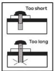
Place on M-C washer on each of the screws, and install the VESA plate directly to your monitor by tightening the screws with hex key (N).
Important! The screws should be tightened until snug. Don't overtighten.

Attaching the Monitor
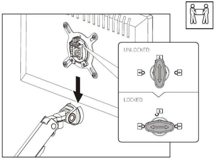
- Once the VESA plate is securely attached to the monitor, slide it into the VESA receiver.
- Turn the VESA lock to the locked position.
Important! The VESA lock secures the VESA plate inside the VESA mount and ensures the monitor won't lift out of the mount when you adjust the monitor height.
To remove the monitor, unlock the VESA lock and lift the monitor off the mount.
Balancing the Arm
You can adjust the arm tension to balance the arm according to the weight of your monitor.
- Remove the end cap from the arm to expose the arm tension screw.
- With the monitor attached, hold the arm horizontally so it's parallel with the desktop.

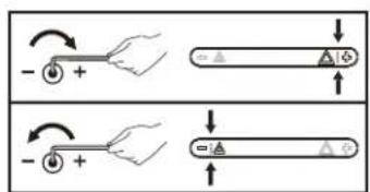
- If the arm drops, tighten the arm tension screw by turning it clockwise with hex key (O) until the monitor stays in the horizontal position.
- If the arm rises, loosen the arm tension screw by turning it counterclockwise with hex key (O) until the monitor stays in the horizontal position.
Important! Do not overtighten the tension screws. To prevent damage to the tension indicator, never let the red indicator line move beyond the + and - signs of the ends of the indicator.
Tip: Always use one hand to support the monitor from below while adjusting the arm tension.
3. When the arm is balanced, replace the end cap.


Adjusting Tilt and Rotation
Tilt and rotation adjustments determine how easily and smoothly you can adjust the screen's position.
Tilt
If the monitor doesn't stay at the desired tilt angle, adjust the tilt tension screw with hex key (N).
Turn clockwise to increase the tension, and counterclockwise to decrease the tension.

Rotation
The monitor should rotate easily, but once it's set at the proper orientation it should stay there.
If the monitor rotates too easily, adjust the rotation tension screws with a Phillips screwdriver.


Adjusting Arm Swivel
The arm can swivel ±180° . However, if the stand is in front of a wall or cubical that can be damaged from contact with the arm or monitor, the arm rotation can be limited to ±90° .
To limit arm swivel to +/-90°, tighten the swivel setscrew on the back of the base arm socket with the screwdriver end of hex key [N]. Don't overtighten.

Note: Make sure to loosen or tighten the swivel setscrew and not the base arm setscrew that's just above it.

Organizing Cables
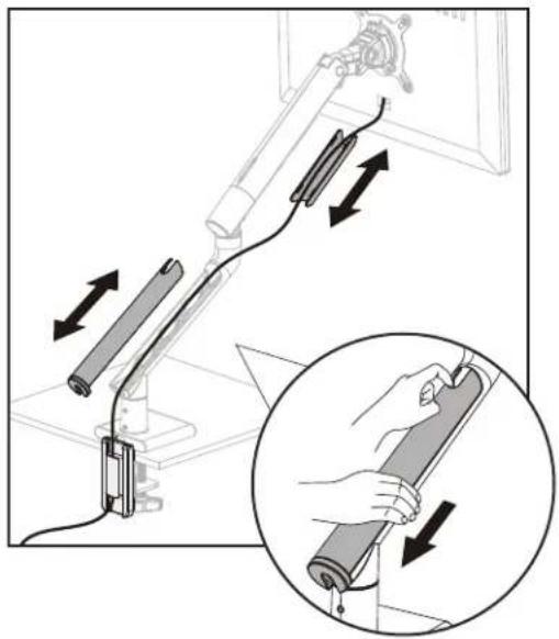
Power and monitor cables can be neatly run through the top and bottom cable guides on the arms.
Top Cable Guide
- Remove the cable guide by sliding it up toward the monitor.
- Place the cables in the guide, and replace it by aligning the notches and sliding it back toward the base until it snaps into place.
Bottom Cable Guide
- Remove the bottom cable guide by sliding it down toward the base.
- Run the cables through the top and bottom holes in the guide, and replace it by sliding it back into place.
Store the Hex Keys
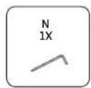
Store the hex keys and keep them handy for future adjustments by sliding them into the holes on the back of the flange.

One-Year Limited Warranty
This Gabor product is warranted to the original purchaser to be free from defects in materials and workmanship under normal consumer use for a period of one (1) year from the original purchase date or thirty (30) days after replacement, whichever occurs later. The warranty provider's responsibility with respect to this limited warranty shall be limited solely to repair or replacement, at the provider's discretion, of any product that fails during normal use of this product in its intended manner and in its intended environment. Inoperability of the product or part(s) shall be determined by the warranty provider. If the product has been discontinued, the warranty provider reserves the right to replace it with a model of equivalent quality and function.
This warranty does not cover damage or defect caused by misuse, neglect, accident, alteration, abuse, improper installation or maintenance. EXCEPT AS PROVIDED HEREIN, THE WARRANTY PROVIDER MAKES NEITHER ANY EXPRESS WARRANTIES NOR ANY IMPLIED WARRANTIES, INCLUDING BUT NOT LIMITED TO ANY IMPLIED WARRANTY OF MERCHANTABILITY OR FITNESS FOR A PARTICULAR PURPOSE. This warranty provides you with specific legal rights, and you may also have additional rights that vary from state to state.
To obtain warranty coverage, contact the Gabor Customer Service Department to obtain a return merchandise authorization ("RMA") number, and return the defective product to Gabor along with the RMA number and proof of purchase. Shipment of the defective product is at the purchaser's own risk and expense.
For more information or to arrange service, visit www.madebygabor.com or call Customer Service at 212-594-2353.
Product warranty provided by the Gradus Group.
www.grodusgroup.com
Gabor is a registered trademark of the Gradus Group. © 2021 Gradus Group LLC. All Rights Reserved.

GABOR®
A Gradus Group Brand
- THANK YOU FOR CHOOSING GABOR
- SAFETY WARNINGS
- PRODUCT SPECIFICATIONS
- CLAMP INSTALLATION
- GROMMET (NON-EDGE) INSTALLATION
- ATTACHING THE ARM
- ATTACHING THE VESA PLATE TO THE MONITOR
- ATTACHING THE MONITOR
- BALANCING THE ARM
- ADJUSTING TILT AND ROTATION
- TILT
- ROTATION
- ADJUSTING ARM SWIVEL
- ORGANIZING CABLES
- TOP CABLE GUIDE
- BOTTOM CABLE GUIDE
- STORE THE HEX KEYS
- ONE-YEAR LIMITED WARRANTY
Brand : Gabor
Model : DM-550
Category : Wall mount