
01729 - Alarm system Vimar - Free user manual and instructions
Find the device manual for free 01729 Vimar in PDF.


| Product type | Two-way radio frequency interface for alarm systems |
| Brand | Vimar |
| Model | 01729 |
| Product line | By-alarm |
| Radio frequency | 868 MHz |
| Modulation | DSSS (Direct Sequence Spread Spectrum) |
| Number of radio input lines | 8 or 16 |
| Power supply | 12 V-- (+/- 20%) |
| Current absorption (LEDs off) | 40 mA max |
| Current absorption (LEDs on) | 80 mA max |
| Ambient conditions | -10°C to +40°C |
| Enclosure dimensions | 145 x 110 x 40 mm |
| Radio range (free field) | 1000 m |
| Maximum number of remote controls | 8 |
| Connection | RS485 serial port (4 conductors) |
| Tamper protection | Two push-buttons (enclosure opening and wall removal) |
| Supervision timer | 8 or 20 minutes (programmable per device) |
| Display | 6 LEDs and alphanumeric display |
| Compatible control panels | Vimar By-alarm 01700 and 01703 |
| Maximum distance from control panel | 600 m via RS485 |
| Installation height | At least 1.5 m above ground |
| Battery life of connected devices | Up to 5 years (depending on configuration) |
Frequently Asked Questions - 01729 Vimar
User questions about 01729 Vimar
0 question about this device. Answer the ones you know or ask your own.
Ask a new question about this device
Download the instructions for your Alarm system in PDF format for free! Find your manual 01729 - Vimar and take your electronic device back in hand. On this page are published all the documents necessary for the use of your device. 01729 by Vimar.
USER MANUAL 01729 Vimar
natural_image
Close-up of an electronic device with a green circuit board and a digital display showing '8.8' (no readable text or symbols beyond basic markings)By-alarm
01729
Two-way radio frequency interface
Table of Contents
- Radio-frequency interface 2
1.1 Main features of DSSS modulation 2
1.2 Technical characteristics 2 - Installing the radio interface 3
2.1 Connection 3 - Radio devices .... 4
- Features of the radio interface 4
4.1 Amber control LED 4
4.2 Tamperproof protection.... 5
4.3 Function LEDs 5 - Configuring the radio interface 6
5.1 Addressing 6 - Supervision 7
6.1 How to program Supervision 7
6.2 Supervision operation 7 - Signal strength 8
- DIP-switches and display messages.... 8
8.1 Functions of the DIP-switches 8
8.2 Key to display messages 9 - Operations on radio frequency detectors.... 9
9.1 Saving 9
9.2 Acquisition of art. 01727.1 and 01728 10
9.2.1 Detector art. 01727.1 10
9.2.2 Detector art. 01728 with separate radio channels.... 11
9.3 Acquisition of art. 01726 and 01731 11
9.4 Selective deletion 12
9.5 Total deletion.... 12 - Operations on remote controls.... 13
10.1 Saving 13
10.2 Acquisition of the Remote Control 13
10.3 Selective deletion 13
10.4 Total deletion 14
Radio frequency interface
1. Radio frequency interface
The radio system is based on DSSS (Direct Sequence Spread Spectrum) modulation using various "codes"; the codes have been chosen so as to have a very low correlation with each other allowing the simultaneous transmission of different systems guaranteeing correct operation.
The spread spectrum modulation, combined with channel coding, enables the communications to reach uncommon distances for the current industry standards, making installations possible without the need to install repeaters.
1.1 Main features of DSSS modulation
- resistance to interference: it is possible to sustain communications with a Signal/Noise ratio of less than 1, that is, with the level of the signal (S) lower than that of the noise (N).
- type of modulation: it makes radio jamming impossible and is virtually immune to any kind of interference.
- high cryptographic capacity: inherent in the signal modulation/demodulation technology.
- full bidirectionality between all the devices: enables minimizing the number of transmissions.
- transmission power: the ability to reduce the power according to the installation requirements makes it possible to extend the life of batteries by even up to 5 years.
1.2 Technical characteristics
| Radio input lines 8 or 16 with single or double balancing, programmable in all the modes contemplated by the control panel | |
| Connections with 4 conductors to one of the RS 485 serial ports as per control panel Instructions | |
| Power supply 12 V— (+/- 20%) | |
| Absorption with LEDs off: 40 mA max. | with LEDs on: 80 mA max. |
| Ambient conditions -10°C.. +40°C |
The radio interface is the module for expanding the number of zones of the control panels 01700 and 01703 via an RS485 serial link up to 600 m away from the control panel.
The control panel manages the radio interface exactly like the input expansion module 01709 and 01704 with which it can be combined, thereby allowing wired and wireless expansions to be used in the same control panel.
- 8 or 16 radio input lines configurable in the same way as the control panel lines.
- Management of remote controls, max 8.
- Collection and differentiated and identified re-addressing to the control panel on an RS485 serial line of the different signals for alarm, tamper, supervision and low battery coming individually from the radio field.
- Push buttons for protecting against tampering with the enclosure.
- Allowed band frequency 868MHz, radio range 1000 m in a free field.
- Enclosure dimensions: 145 x 110 x 40 mm.
2. Installing the radio interface
When securing the radio interface and to improve its operation, follow these instructions:
- do not remove the circuits from the plastic enclosure.
- do not install near metal objects and devices that generate radio frequencies (televisions, computers, routers, hot spots, etc.)
- install at a height of not less than 1.5 m off the ground in a location as central as possible to the position of the devices.
- install with the terminals facing downwards and the aerial set in a vertical position.
- cable entry must be as far away from the aerial as possible and, therefore, from the bottom side using the holes, making sure that they do not overlap it.
2.1 Connection
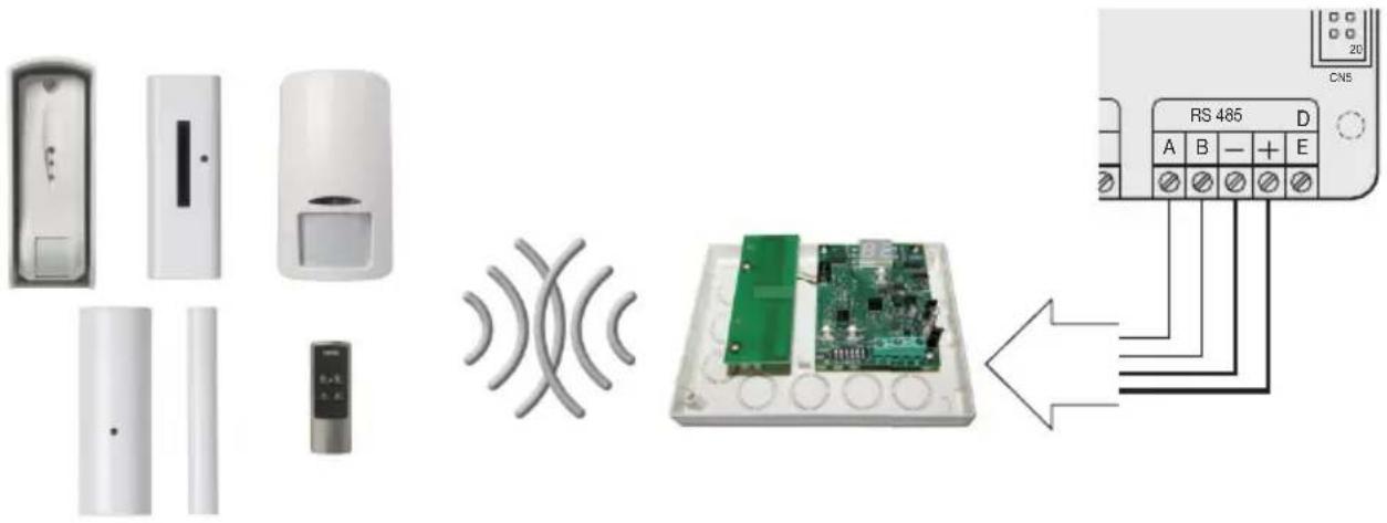
The radio interface with 8 or 16 input lines, in a self-protected plastic enclosure, is connected to the control panel to one of the branches of the RS485 serial ports like any serial device, following the instructions given in the control panel installation manual, respecting their abbreviations.
So, 2 conductors carry the power supply positive and negative, and another two the connections A and B referring to the signals.
For the 12 V- power supply it is necessary to use conductors of at least 0.50 mm ^2 and of 0.22 mm ^2 for the signals; the shielding must be connected to the negative terminal on the control panel side and left free on the interface side.
Radio devices - Radio interface features
3. Radio devices
01726: By-alarm curtain detector to protect entrances and openings such as doors, windows, covered terraces, corridors and French doors, 868 MHz radio frequency connection, surface mounting, powered by 1 lithium battery 3 V CR2477 (included).
01727.1: By-alarm magnetic RF contact + shock sensor, 868 MHz radio frequency connection, powered by 1 lithium battery 3 V CR123A (included).
01728: By-alarm passive infrared presence detector, 868 MHz radio frequency connection, 1 input for external magnetic contact, powered by one 3V CR123 battery (included).
01730: By-alarm remote control with two-way 868 MHz radio frequency connection, powered by one 3V CR2032 battery (included).
01731: By-alarm IP54 curtain radio frequency detector for outdoor use, with dual technology, to protect entrances and openings such as doors, windows, covered terraces, corridors and French doors, surface mounting, powered by 1 3 V CR2 lithium battery (supplied).
4. Features of the radio interface
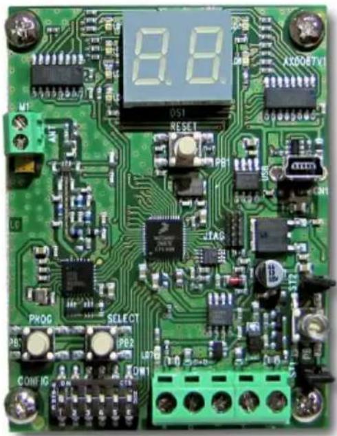
The function of the radio interface is to receive data from multiple devices and send them to the control panel; it also oversees the supervision of the life of the devices.
natural_image
Close-up of a green printed circuit board with electronic components and a digital display (no readable text or symbols)4.1 Amber control LED
An amber LED on the interface board, as in the photo above, lets you check the operation of the board.
On steady:
- powered correctly, but with no serial communication.
Flashing with a frequency of 1 s:
- Powered correctly and receiving serial communications, but not sent with the correct address or no programming for that device in the control panel.
Features of the radio interface
Flashing with a short pulse every second:
- Correct power supply and serial communication.
4.2 Tamperproof protection
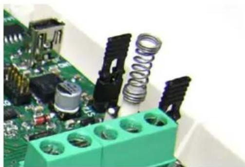
The board has 2 push-buttons to protect against enclosure opening and against tearing it off the wall that can be excluded by closing the relevant jumpers under the push-buttons themselves.
natural_image
Close-up of electronic circuit boards with various components and connectors (no visible text or symbols)Keying in the Installer Code inhibits every kind of alarm, and thus also all the tamper-proof protections will be blocked.
When commissioning the control panel, the cut-off jumpers ST1 and ST2 of the tamper-proof protections must be removed to make the protections active.
4.3 Function LEDs
On the board there are six LEDs and a display that shows the various states of the interface.
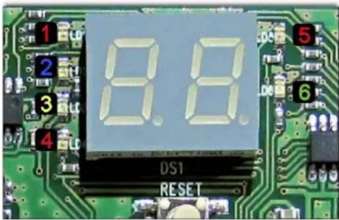
During normal operation, the LEDs are off and the display cyclically shows the various associated devices. In the event of an alarm and/or malfunctioning of a device, the interface will immediately display the number of the relevant device and one of the LEDs on the left of the display will light up to indicate its cause.
If multiple devices were simultaneously in an alarm and/or fault status, the interface display would cycle through the states of the various devices concerned.
Configuring the radio interface
The LEDs have the following meanings:
- 1: Red LED -> tamper zone.
- 2: Blue LED -> zone under supervision.
- 3: Amber LED -> battery fault zone.
- 4: Red LED -> zone in alarm status.
- 5: Red LED -> signalling transmission of a data packet from the interface to a device.
- 6: Green LED -> signalling receiving a data packet from a device to the interface.
5. Configuring the radio interface
The radio interface integrates completely, considering the different possibilities, with all the By-alarm control panels 01700 and 01703.
5.1 Addressing
To be recognized, the interfaces connected to the control panel need to be appropriately addressed.
N.B. The address to be associated with the interface must be different from the addresses previously assigned to other interfaces 01729 or input expansion modules 01709 and 01704. The addresses must be assigned in a sequential manner, ie assigning ID=1 to the first device, 2 to the second one, and so on.
To address the interfaces carry out the following procedure:
a. Power up the interface; the display will show the symbol --.
b. Set DIP-switch 5 to ON and the display will show In (Address).
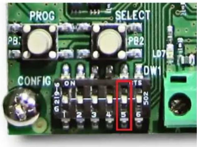
c. Press the SELECT button to display the currently programmed address.
d. Press the PROG button and the display will show Pr (programming).
e. Press the SELECT button to change the value of the address (from 01 to 32). The highest address that can be assigned depends on the type of control panel installed (see the relevant manuals).
f. Press the PROG button to confirm the address, the display will show In.
g. At the end, set DIP-switch 5 back to OFF.
Supervision
Note: Take care to write down all the IDs assigned to the interfaces 01729 because later on, when configuring via the keypad or By-alarm Manager software, you will have to associate the same value. Depending on the ID assigned and the selection for the 8 or 16 radio Inputs, the control panel will assign 8 or 16 zones according to the numbering that depends on the presence of other interfaces 01729 and input expansion modules 01709-01704 and the IDs assigned to them.
If the zones supported by the By-alarm control panel are exceeded (24 for 01700 and to 64 for 01703), the inputs, even if configured, are ignored.
6. Supervision
The supervision mechanism is based on periodically sending data packets from each single device to the radio interface.
Since the data packet sent from the device also contains a unique identification code, each single transmission is also interpreted as a survival message.
For obvious reasons, the remote controls are not subject to supervision.
6.1 How to program Supervision
a. Set the DIP-switches 2 and 3 to ON and the display will show SU (supervision).
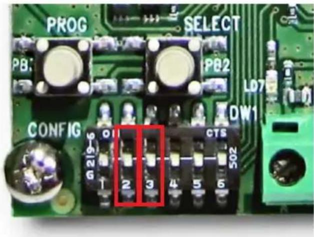
b. Press the SELECT button to display the state of supervision.
c. Press the PROG button to deactivate -NO- or activate -YES- supervision.
d. At the end, set the DIP-switches 2 and 3 back to OFF.
6.2 Supervision operation
After the phase of installing the devices, the radio interface starts supervision control.
After each transmission, the device starts a timer lasting 8 or 20 minutes (the duration varies according to the programming done on the device); when this time elapses, the device sends a survival message and expects a confirmation message from the radio interface.
If the radio interface does not receive the expected message, the control panel signals the situation of failing to send the Supervision communication for that device.
Signal strength - DIP-switches and display messages
7. Signal strength
To check the strength of the radio signal of each single device during transmission, you can activate this specific function.
a. Set the DIP-switches 1, 2 and 3 to ON and the display will show SE (signal).
b. Press the SELECT button to scroll through the installed devices.
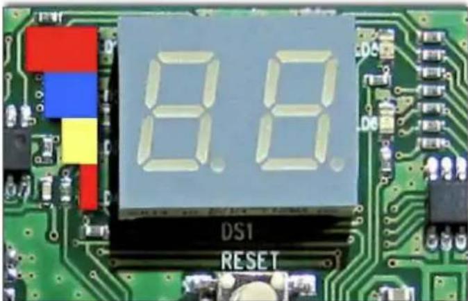
Depending on how many LEDs light up, you will be able to assess the strength of the signal received by the radio interface.
- 4 LEDs: excellent level.
- 3 LEDs: good level.
- 2 LEDs: sufficient level.
- 1 LED: minimum level.
d. At the end, set the DIP-switches 1, 2 and 3 back to OFF.
8. DIP-switches and display messages
8.1 Functions of the DIP-switches
| DIP-switch 1 | DIP-switch 2 | DIP-switch 3 | DIP-switch 4 | DIP-switch 5 | DIP-switch 6 | function |
| off off | off xxx xxx | xxx Standard operation | ||||
| on off | off xxx xxx | xxx Delete | contacts and sensors | |||
| off on | off xxx xxx | xxx Delete | Remote Controls | |||
| on on | off xxx xxx | xxx Install | contacts and sensors | |||
| off off | on xxx xxx | xxx Install | remote controls | |||
| off on | on xxx xxx | xxx Supervision | ||||
| on on | on xxx xxx | xxx Signal | strength detected | |||
| xxx xxx | xxx xxx on | xxx Interface addressing | ||||
Operations on radio frequency detectors
8.2 Key to display messages
| In | Address |
| Pr | Programming |
| tU | All |
| Id | Install contacts and detectors |
| It | Install Remote Controls |
| Cd | Delete contacts and detectors |
| Ct | Delete Remote Controls |
| Su | Supervision |
| SE | Signal strength detected |
| -- | Ok |
| CA | Delete |
| Er | Error |
9. Operations on radio frequency detectors
As explained above, the interface can have 8 or 16 radio inputs to be set during configuration; the relationship between these inputs and the alarm zones in the control panel depends on the addresses assigned to the interfaces 01729 and any input expansion modules 01709 and 01704 that may be present.
9.1 Saving:
a. Set the DIP-switches 1 and 2 to ON; the display will show /d (Installing Devices).
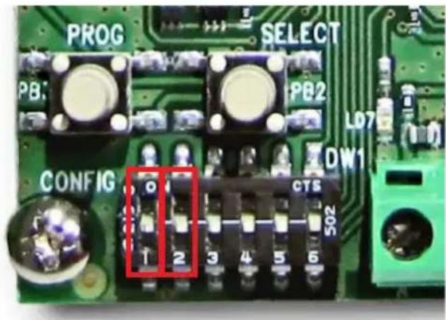
b. Press the SELECT button to scroll through the free addresses on which to pair the devices.
c. Run the procedure for installing the device (refer to its installer sheet).
d. If saving is successful, the display will show the next free address for a new acquisition.
e. At the end, set the DIP-switches 1 and 2 back to OFF.
Caution: If the display shows E r, it means there has been an error when saving; in which case, press the SELECT button and run the procedure again.
Operations on radio frequency detectors
9.2 Acquisition of art. 01727.1 and 01728
Below is the general procedure for the acquisition of the detector 01727.1 (the procedure is similar for detectors 01728 since the push buttons to press have the same wording).
Caution: Before acquiring the device, you need to set all its parameters as described in the respective instruction sheets (see instruction sheet for art. 01727.1 and for art. 01728 for all the configurations of the devices themselves).
- Set up the radio interface for the acquisition of the device (as specified in points a. and b. of paragraph 9.1).
- Power the Device.
- Press and hold down the SELECT push button.
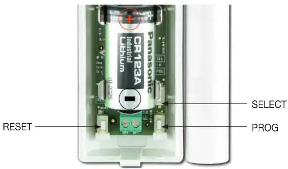
- Press and release the RESET push button.
- Release the SELECT push button after the LEDs on the device have lit up in sequence. If the detector has been programmed to use the IN input on separate radio channels, go directly to the procedure described in para. 9.2.1 (for art. 01727.1) and in para. 9.2.2 (for art. 01728).
- If the detector has been programmed to use a single radio channel (REED + IN on the same channel for art. 01727.1), press and release the SELECT push button to confirm the acquisition of the device and the three LEDs will light up permanently for approximately 2 s. If they flash, this means there has been an acquisition error; in this case the procedure needs to be repeated.
9.2.1 Detector art. 01727.1
If the detector 01727 has been configured for use with the IN input on separate channels, follow the procedure below:
- Press the PROG push button to select the channel to save as shown by the LEDs lighting.
LEDs off = Channel 1
Yellow LED lit = Channel 2
Green LED lit = Channel 3
- Press the SELECT push button to confirm your selection.
Operations on radio frequency detectors
- If the storage is successful, the interface display will show the subsequent free address that can be used for a new acquisition.
- If the interface display shows the message E_r repeat the detector channel configuration as described above.
- If the configuration was successful and correct, the interface will show the subsequent free address.
- Then continue from point d. of paragraph 9.1.
9.2.2 Detector art. 01728 with separate radio channels
If the detector 01728 has been configured for use with the IN input on a separate channel, follow the procedure below:
- Press the PROG push button to select the channel to save as shown by the LEDs lighting.
LEDs off = Channel 1 (infrared)
Yellow LED lit = Channel 2 (IN)
- Press the SELECT push button to confirm your selection.
- If the storage is successful, the interface display will show the subsequent free address that can be used for a new acquisition.
- If the interface display shows the message E_r repeat the detector channel configuration as described above.
- If the configuration was successful and correct, the interface will show the subsequent free address.
- Then continue from point d. of paragraph 9.1.
N.B.: When the auxiliary IN inputs are also enabled in the radio frequency device parameters, by choosing to set them on separate channels the storage of each of these inputs will occupy a dedicated channel of the interface 01729; therefore, according to the associated radio channel, it will be assigned to a related zone in the system.
9.3 Acquisition of art. 01726 and 01731
Below is the general procedure for the acquisition of the detector 01726 (the procedure is similar for detectors 01731 since the push buttons to press have the same wording).
Caution: Before acquiring the device, you need to set all its parameters as described in the respective instruction sheets (see instruction sheet for art. 01726 and for art. 01728 for all the configurations of the devices themselves).
- Set up the radio interface for the acquisition of the device (as specified in points a. and b. of paragraph 9.1).
- Power the Device.
- Press and hold down the SELECT push button.
- Press and release the RESET push button.
- Release the SELECT push button after the LEDs on the device have lit up in sequence.
- Press the SELECT push button to confirm your selection.
- If the storage is successful, the interface display will show the subsequent free address that can be used for a new acquisition.
- If the interface display shows the message E_r repeat the detector channel configuration as described above.
- If the configuration was successful and correct, the interface will show the subsequent free address.
Operations on radio frequency detectors
9.4 Selective deletion
a. Set the DIP-switch 1 to ON; the display will show Cd (delete devices).
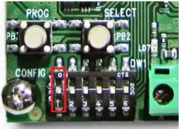
b. Press the SELECT button and the display will show U (All).
c. Press the SELECT button to scroll through the devices installed in the system.
d. Press the PROG button you have decided which device to delete, the display will show CR (Delete).
e. Press the PROG button to confirm deletion and the display will show - - .
f. Press the SELECT button to continue scrolling through the devices installed in the system.
g. At the end, set DIP-switch 1 back to OFF.
9.5 Total deletion
a. Set the DIP-switch 1 to ON; the display will show Cd (Delete Devices).
b. Press the SELECT button and the display will show U (All).
c. Press the PROG button for total deletion, the display will show CR (Delete).
d. Press the PROG button to confirm deletion and the display will show - -
e. At the end, set DIP-switch 1 back to OFF.
Operations on remote controls
10. Operations on remote controls
10.1 Saving:
a. Set the DIP-switch 3 to ON and the display will show It (Install Remote Controls).
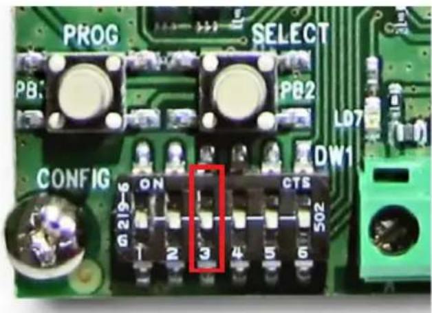
b. Press the SELECT button to scroll through the free addresses for remote control acquisition.
c. Run the procedure for installing the remote control (refer to its installer sheet).
d. If saving is successful, the display will show the next free address for a new acquisition.
e. At the end, set DIP-switch 3 back to OFF.
Caution: If the display shows E_r , it means there has been an error when saving; in which case, press the SELECT button and run the procedure again.
10.2 Acquisition of the Remote Control
The general procedure for acquiring the Remote Control is illustrated below (for all the various configurations, refer to the relevant instruction sheet).
- Prepare the radio interface for acquiring the device (as per points a. and b. of subsection 9.1).
- Insert the battery in the remote control, if not already inserted.
- Press remote control buttons and together.
- The LEDs inside the remote control will emit a short flash for a moment and will light up steady on the response of the radio interface.
- Then continue from point d.
10.3 Selective deletion
a. Set the DIP-switch 2 to ON; the display will show (Delete Remote Controls).
b. Press the SELECT button and the display will show t U (All).
c. Press the SELECT button to scroll through the devices installed in the system.
d. Press the PROG button you have decided which device to delete, the display will show CR (Delete).
e. Press the PROG button to confirm deletion and the display will show - - .
f. Press the SELECT button to continue scrolling through the devices installed in the system.
g. At the end, set DIP-switch 2 back to OFF.
Operations on remote controls
10.4 Total deletion
a. Set the DIP-switch 2 to ON; the display will show (Delete Remote Controls).
b. Press the SELECT button and the display will show U (All).
c. Press the PROG button for total deletion, the display will show CR (delete).
d. Press the PROG button to confirm deletion and the display will show - - .
e. At the end, set DIP-switch 2 back to OFF.
- Table of Contents
- Radio frequency interface
- Radio frequency interface
- Main features of DSSS modulation
- Technical characteristics
- Installing the radio interface
- Connection
- Radio devices - Radio interface features
- Radio devices
- Features of the radio interface
- Amber control LED
- On steady:
- Flashing with a frequency of 1 s:
- Features of the radio interface
- Tamperproof protection
- Function LEDs
- Configuring the radio interface
- Configuring the radio interface
- Addressing
- Supervision
- Supervision
- How to program Supervision
- Supervision operation
- Signal strength - DIP-switches and display messages
- Signal strength
- DIP-switches and display messages
- Functions of the DIP-switches
- Operations on radio frequency detectors
- Key to display messages
- Operations on radio frequency detectors
- Saving:
- Acquisition of art. 01727.1 and 01728
- Detector art. 01727.1
- Detector art. 01728 with separate radio channels
- Acquisition of art. 01726 and 01731
- Selective deletion
- Total deletion
- Operations on remote controls
- Operations on remote controls
- Saving:
- Acquisition of the Remote Control
- Selective deletion
- Total deletion
Brand : Vimar
Model : 01729
Category : Alarm system