
GLD Digital Audio Mixing System - Mixing console ALLEN & HEATH - Free user manual and instructions
Find the device manual for free GLD Digital Audio Mixing System ALLEN & HEATH in PDF.


| Product Type | Digital Audio Mixing System |
| Brand | Allen & Heath |
| Model | GLD |
| Dimensions (W x D x H) | Approx. 19" x 20" x 7" (rack mountable with ears) |
| Weight | Approx. 25 lbs (11.3 kg) |
| Power Supply | 100-240 VAC, 50-60 Hz, 200W max |
| Audio Channels | 48 input channels (mixable to 32 buses plus LR) |
| Built-in DSP | FPGA-based processing with 96kHz sampling rate |
| Recallable Preamps | Up to 48 analog inputs with recallable gain, pad, phantom power |
| Touchscreen Display | 12.5" daylight-visible capacitive touchscreen |
| Audio Networking | dSNAKE digital snake support, optional Dante card |
| Mixer Control | Fader bank of 8 motorized faders plus touchscreen and rotary encoders |
| Effects Processing | Built-in 4 stereo DSP effects engines (reverb, delay, modulation, etc.) |
| Graphic Equalizers | 8 stereo graphic EQs assignable to outputs |
| Storage & Recall | Scene memory, show files on USB drive |
| Remote Control | LAN/USB connectivity for remote mixing via tablet or PC |
| Cleaning Instructions | Wipe with a dry soft cloth; avoid liquids and abrasive cleaners |
| Safety Certifications | CE, FCC, RoHS compliant |
| Spare Parts Availability | Authorized service centers; contact Allen & Heath for parts |
| Reparability | Modular design; faders, encoders, and power supply replaceable by technician |
| Warranty | Standard 3-year limited warranty (check local terms) |
Frequently Asked Questions - GLD Digital Audio Mixing System ALLEN & HEATH
User questions about GLD Digital Audio Mixing System ALLEN & HEATH
0 question about this device. Answer the ones you know or ask your own.
Ask a new question about this device
Download the instructions for your Mixing console in PDF format for free! Find your manual GLD Digital Audio Mixing System - ALLEN & HEATH and take your electronic device back in hand. On this page are published all the documents necessary for the use of your device. GLD Digital Audio Mixing System by ALLEN & HEATH.
USER MANUAL GLD Digital Audio Mixing System ALLEN & HEATH
natural_image
Exterior view of a digital audio workstation with multiple audio equipment racks and a central control panel (no visible text or labels)GLD Digital Audio Mixing System
User Guide
For firmware Version V1.1
Check the Allen & Heath web site for the latest version available
Limited One Year Manufacturer's Warranty
This product is warranted to be free from defects in materials or workmanship for period of one year from the date of purchase by the original owner.
To ensure a high level of performance and reliability for which this equipment has been designed and manufactured, read this User Guide before operating.
In the event of a failure, notify and return the defective unit to the place of purchase. If this is not possible then please contact the authorised ALLEN & HEATH distributor or agent in your country as soon as possible for repair under warranty subject to the following conditions:
Conditions Of Warranty
The equipment has been installed and operated in accordance with the instructions in this User Guide.
The equipment has not been subject to misuse either intended or accidental, neglect, or alteration other than as described in the User Guide or Service Manual, or approved by ALLEN & HEATH.
Any necessary adjustment, alteration or repair has been carried out by an authorised ALLEN & HEATH distributor or agent.
This warranty does not cover fader wear and tear.
The defective unit is to be returned carriage prepaid to the place of purchase, an authorised ALLEN & HEATH distributor or agent with proof of purchase. Please discuss this with the distributor or the agent before shipping.
If the unit is to be repaired in a different country to that of its purchase the repair may take longer than normal, whilst the warranty is confirmed and parts are sourced.
Units returned should be packed to avoid transit damage.
In certain territories the terms may vary. Check with your ALLEN & HEATH distributor or agent for any additional warranty which may apply.
If further assistance is required please contact Allen & Heath Ltd.

The GLD range of products complies with the European Electromagnetic Compatibility directives 2004/108/EC and the European Low Voltage directives 2006/95/EC.
Any changes or modifications to the equipment not approved by Allen & Heath could void the compliance of the product and therefore the users authority to operate it.
GLD User Guide AP8561 Issue 2
Copyright © 2013 Allen & Heath. All rights reserved
ALLEN&HEATH
Allen & Heath Limited, Kernick Industrial Estate, Penryn, Cornwall, TR10 9LU, UK
http://www.allen-heath.com
IMPORTANT - Read these instructions before starting:
Safety instructions
Before starting, read the Important Safety Instructions printed on the sheets supplied with the equipment. For your own safety and that of the operator, technical crew and performers, follow all instructions and heed all warnings printed on the sheet and on the equipment panels.
System operating firmware
The function of the GLD is determined by the firmware (operating software) that runs it. Firmware is updated regularly as new features are added and improvements made. This guide relates to Version 1.1 firmware.
The latest firmware can be downloaded from the Allen & Heath web site, transferred to USB key and then loaded into the GLD mixer using the Firmware Update utility. If the AudioRack firmware is different to that running on the mixer it is automatically updated by the GLD mixer when the mixer powers up.
- Check the Allen & Heath web site for the latest version of GLD firmware.
Software licence agreement
By using this Allen & Heath product and the software within it you agree to be bound by the terms of the relevant End User Licence Agreement (EULA), a copy of which can be found on the Allen & Heath website in the product's pages and in the About section of the GLD built-in Help Manual. You agree to be bound by the terms of the EULA by installing, copying, or using the software.
Further information
For further information about the GLD please refer to the user guides associated with each system component. Also refer to the GLD Touch Screen Reference Guide available on the web site, and use the on-screen Help Manual available on the GLD-80 surface. Refer to the Allen & Heath web site for additional downloads, resources, knowledgebase and technical support.
General precautions
- To prevent damage to the controls and cosmetics, avoid placing heavy objects on the control surface, obstructing movement of the motorised faders, scratching the surface or touch screen with sharp objects, or rough handling and vibration.
- Protect the equipment from damage through liquid or dust contamination. Avoid dust or small objects getting into the fader slots. Cover the mixer when it is not being used for a long period.
- Computer and touch screen technology can be affected by extreme cold. If the equipment has been stored in sub-zero temperatures allow time for it to reach normal operating temperature before use at the venue. Recommended operating temperature for GLD is 5 to 35 degrees Celsius.
- Avoid using the equipment in extreme heat and direct sunlight. Make sure the mixer and rack ventilation slots are not obstructed and that there is adequate air movement around the equipment.
- Transport the GLD-80 using a touring grade, purpose designed flightcase with adequate foam lining and internal support for protection.
- Clean the control surface with a soft brush and dry lint-free cloth. Avoid the use of chemicals, abrasives or solvents.
- It is recommended that servicing is carried out only by an authorised Allen & Heath agent. Contact details for your local distributor can be found on the Allen & Heath web site. Allen & Heath do not accept liability for damage caused by maintenance, repair or modification by unauthorised personnel.
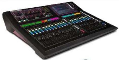
GLD-80 Mixer
natural_image
Audio editing instrument with multiple audio and sound wave displays (no visible text or labels)
User Guide
AP8561
Mains lead • Check this is correct for your territory
Safety Sheets
AP3345 - English
AP7287 – French
AP8513 – Chinese
- Read this before starting
Registration Card AP3594
- Return the card or register online at www.allen-heath.com
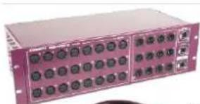
GLD-AR2412 AudioRack
natural_image
Front view of a purple rack-mounted electronic device with multiple ports and indicator lights (no visible text or labels)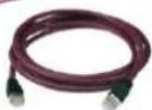
CAT5 cable 2m (6.6')
AH8822
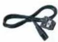
Mains lead • Check this is correct for your territory
Information
AP8596
Safety Sheets
AP3345 – English
AP7287 – French
AP8513 – Chinese
- Read this before starting
Registration Card AP3594
- Return the card or register online at www.allen-heath.com
GLD-AR84 AudioRack

natural_image
Exterior view of a pink industrial rack-mounted device with multiple ports (no visible text or labels)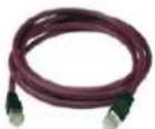
CAT5 cable 2m (6.6')
AH8822
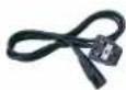
Mains lead • Check this is correct for your territory
Information
AP8720
Safety Sheets
AP3345 – English
AP7287 – French
AP8513 – Chinese
- Read this before starting
Registration Card AP3594
- Return the card or register online at www.allen-heath.com
Accessories available
The 2m CAT5 cable shipped with the GLD AudioRack is to get you started or for local connection. For longer distances refer to the Allen & Heath web site for information on recommended cable types. The following are available from Allen & Heath:
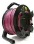
120m (396') CAT5 drum
AH8721 • For use with dSNAKE and ACE ^TM connection only
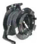
80m (264') CAT5 drum
AH7000 • For use with all GLD CAT5 connections
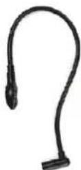
LEDlamp
Part LEDlampX
Right angled 4-pin XLR with built-in dimmer
Soft cover for GLD-80 AP8806
Black, water repellent polyester
Table of Contents
Read before starting.... 3
Packed contents, registration and accessories 4
GLD systems.... 6
Introduction......8
System block diagram.... 10
Input and output sockets.... 11
GLD-80 Mixer controls 12
GLD-80 Mixer rear connectors 13
GLD-AR2412 main AudioRack.... 14
GLD-AR84 expander AudioRack 15
Connect and power up.... 16
GLD Remote iPad app and wireless router 17
Recall a Template Show as a starting point.... 18
A few things to know before starting....21
Working with Scenes.... 25
User Profiles....26
USB Playback and Recording 27
How to update GLD system Firmware 28
Specification 30
Dimensions and weights....31
Quick start sheet.... 32
Important note about this guide
This user guide relates to Version 1.1 GLD firmware and is to help you get started setting up and using the GLD.
Some details shown in this guide may differ from those in the current release of firmware. Please refer to the GLD Touch Screen Reference Guide which can be downloaded from the Allen & Heath web site, and to the Help Manual built into the GLD mixer for information on advanced functions not described in this guide.
- Check the Allen & Heath web site for the latest version of this guide.
- Check the Allen & Heath web site for the latest version of GLD firmware.
- A single sheet Quick Start Mixing Guide is provided at the rear of this user guide.
Systems
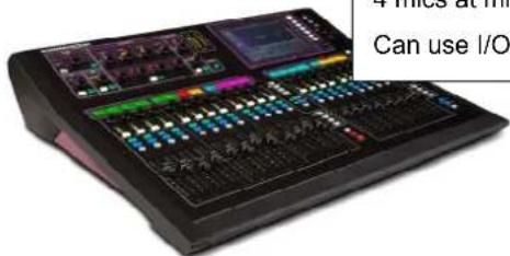
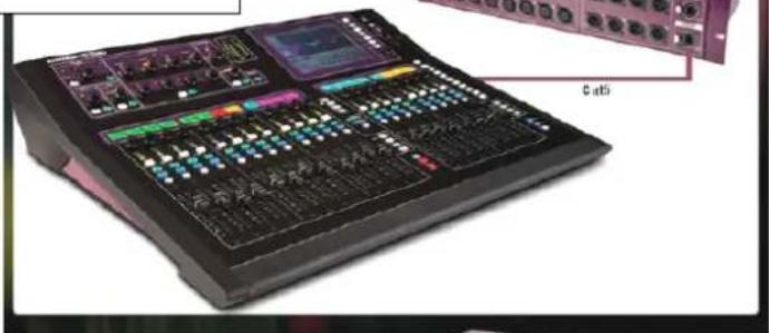
GLD-80 only 8 in (4 mics), 10 out
4 mics at mixer
Can use I/O module option for networked audio
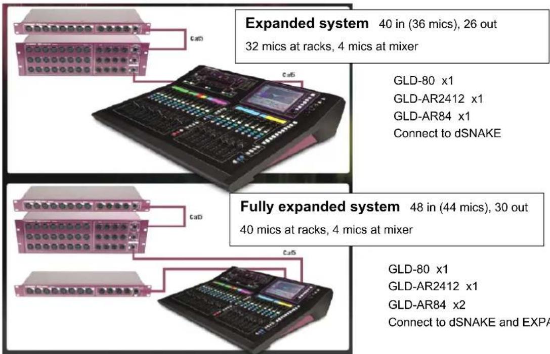
Standard system 32 in (28 mics), 22 out
24 mics at rack, 4 mics at mixer
GLD-80 x1
GLD-AR2412 x1
Connect to dSNAKE
natural_image
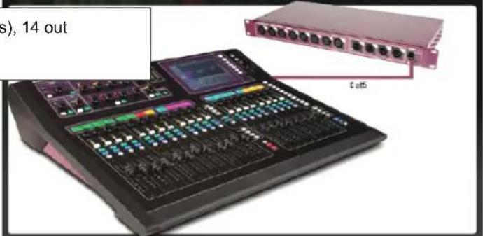
Audio mixing console with multiple audio and audio jack knobs (no visible text or labels)Compact system 16 in (12 mics), 14 out
8 mics at rack, 4 mics at mixer
GLD-80 x1
GLD-AR84 x1
Connect to EXPANDER
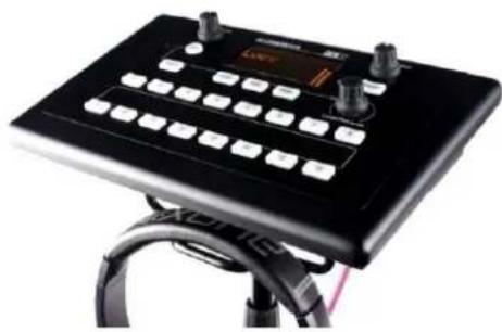
The GLD can interface directly with the Allen & Heath ME Personal Mixing System to allow musicians, performers and presenters to control their own monitor mix without using up GLD mix buses.
Visit the Allen & Heath web site to find out more.
natural_image
Black electronic device with control panel and keyboard, mounted on a stand with cables (no visible text or symbols)ME-1 Personal Mixer
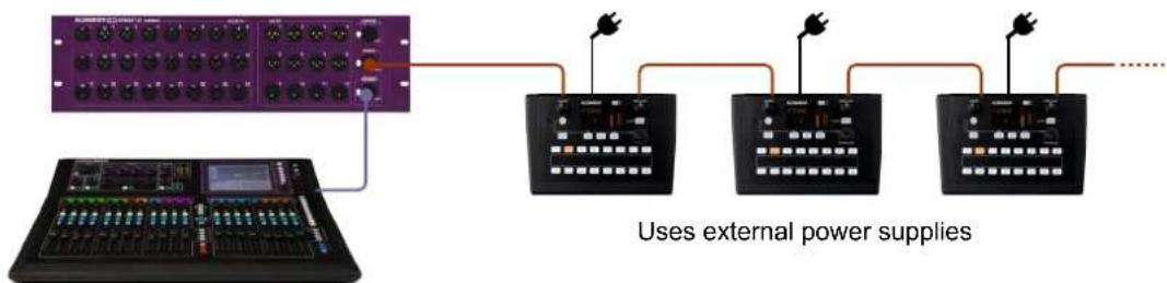
Daisy chain connection One or more ME-1 personal mixers can connect to any GLD dSNAKE port (dSNAKE, Expander, Monitor).
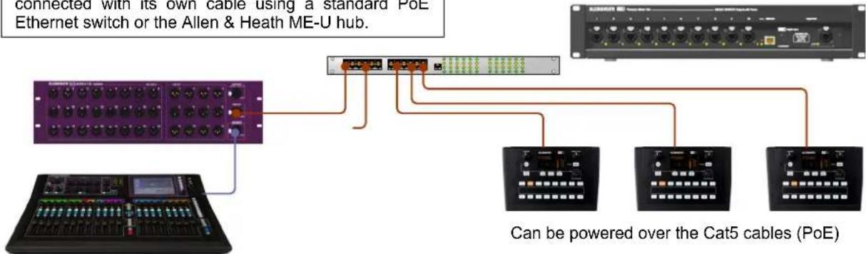
Parallel connection Each ME-1 mixer can be connected with its own cable using a standard PoE Ethernet switch or the Allen & Heath ME-U hub.
ME-U 10-port PoE Hub
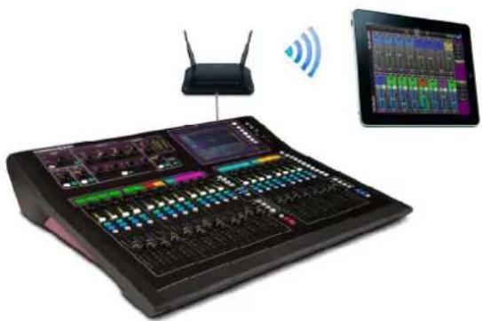
GLD Remote app for iPad
Allows remote wireless control using one or more iPads via a wireless access point (router) connected to the GLD Network port.
The app can be downloaded from the Apple Store.
natural_image
Digital audio workstation with network interface and tablet displaying multiple audio streams (no visible text or labels)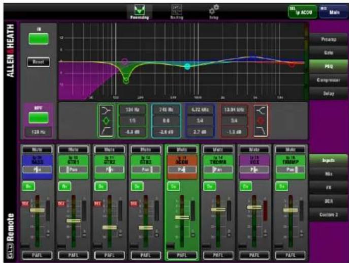
Introduction
GLD is an affordable live sound digital audio mixing system from Allen & Heath. At its low price point and with its intuitive user interface and 'plug n play' connection it provides the perfect upgrade for users of analogue mixers such as the Allen & Heath GL Series, and for small to mid-sized venues, tours and rental companies looking for an affordable yet fully featured and configurable professional digital solution that is easy to learn, operate and maintain.
GLD components
The heart of the system is the GLD-80 Mixer. The DSP is located in the mixer and can process 48 channels x 30 buses x 20 mix outputs plus 8 'RackFX' internal effects devices with dedicated return channels bringing the total number of sources able to feed the mix to 56. The rear panel provides connections for 8 inputs and 10 outputs plus an option slot to fit one of several audio networking cards available from Allen & Heath.
Adding one or more of the available AudioRacks lets you configure systems with up to 40 remote mic inputs in addition to the mixer rear connections. This gives you a distributed audio system with convenient CAT5 digital snake based on the proprietary Allen & Heath dSNAKE protocol. The main I/O (Input/Output) rack is the GLD-AR2412 AudioRack providing 24 mic/line inputs and 12 line outputs. It also features a MONITOR port compatible with the Allen & Heath ME and Aviom® personal mixing systems. The GLD-AR84 AudioRack is an expander I/O remote rack adding an extra 8 mic/line inputs and 4 line outputs. You can add up to two GLD-AR84 racks, one at the GLD-AR2412, the other at the GLD-80 mixer.
Compatibility with iLive
GLD is not compatible with iLive components, firmware, Libraries or Show files. However, it is compatible with the range of iLive Port B option cards letting you interface easily between GLD and iLive or other systems using a digital snake such as ACE, MADI, EtherSound or Dante.
Key features
- Plug and play components for systems from 4 to 44 mics
- Easy to use, quick access, analogue style interface with 8.4" colour touch screen
- Remote I/O using dSNAKE CAT5 digital snake - up to 120m (400') length
• High grade 1dB/step recallable mic/line preamps
• 48 channels into 30 buses into 20 outputs – assignable mono/stereo Group, Aux, FX, Main, Matrix - 8 stereo RackFX engines with dedicated return channels – total 56 sources to the mix
- 64 channel I/O network card option for FOH/Monitor split, recording, link to iLive and more
• Full processing on all inputs – Preamp, trim, polarity, HPF, insert, Gate, PEQ, Compressor, Delay
• Full processing on all outputs – Ext input, Insert, PEQ, GEQ, Compressor, Delay
• Dedicated keys for quick Copy/Paste/Reset of mixes and processing parameters - Input, insert and output soft patchbays
- 20 faders, 2 Banks of 4 Layers each – 80 freely assignable strips for custom layout
• Virtual write-on strip – 8 colour backlight LCD strip display for naming and colour coding
• 10 user assignable SoftKeys
• 16 DCA / Mute groups - Compatible with the Allen & Heath ME personal mixing system and Aviom ^® A-Net 16.
• USB stereo recording and playback
• Built-in Talkback, RTA display, Signal Generator - Monitor mode features – Input override output PAFL, engineer's Wedge and IEM strips
- GLD Remote iPad app for wireless mixing and parameter control
• MIDI In/Out and Network ports - Libraries, Scenes and Show memories
• 10 User Profiles for restricted operator access
• Get started quickly with Template Shows for classic FOH or Monitor configuration
System block diagram
The block diagram here shows the audio signal flow and processing through the GLD-80.
The GLD-AR2412 and GLD-AR84 AudioRacks provide inputs as shown in the 'Remote Inputs' box, and outputs as shown in the 'Remote Outputs' box. These signals connect to the GLD-80 via the dSNAKE or EXPANDER ports.
Note the options available for AUX sends, FX sends and global Direct Out. Configuration possibilities are shown for the MIX masters.
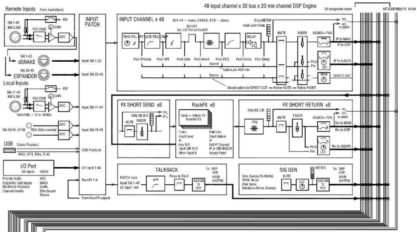
flowchart
48-bit multi-channel DSP engine block diagram showing signal flow from input sources through DACs, transceivers, and output modules to final outputs.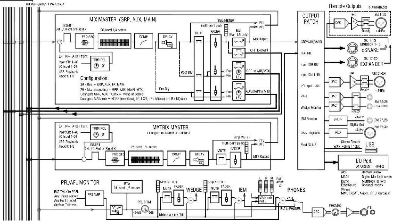
flowchart
Audio signal processing flowchart for MIX MASTER and MATRIX MASTER, showing signal paths from input to output patches with component blocks like PEQ GEO, FADER, and DAC.Input and output sockets
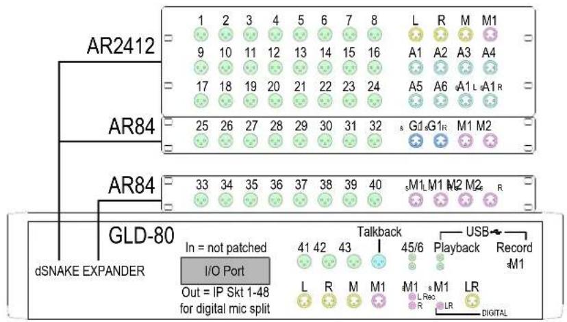
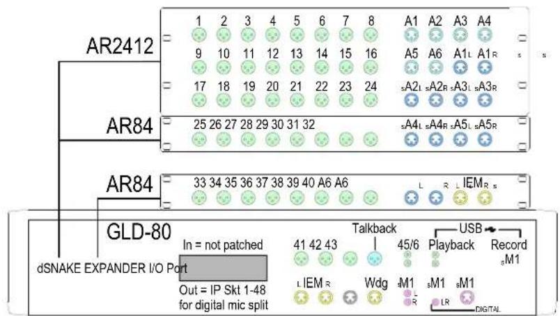
The diagram here shows the interconnection and socket numbering of the fully expanded system.
Each socket has a unique number. The physical socket numbers are shown below. Any input socket or source can be patched to any of the 48 channels. Any mix or other GLD signal can be patched to any of the output sockets.
The default is one-to-one mapping, ie. Socket 1>CH1, Socket 2>CH2 and so on.
| Input Sockets Mixer dSNAKE: GLD-AR2412 Main rack: 1 XLR mic 2 XLR mic 3 XLR mic 4 XLR mic 5 XLR mic 6 XLR mic 7 XLR mic 8 XLR mic 9 XLR mic 10 XLR mic 11 XLR mic 12 XLR mic 13 XLR mic 14 XLR mic 15 XLR mic 16 XLR mic 17 XLR mic 18 XLR mic 19 XLR mic 20 XLR mic 21 XLR mic 22 XLR mic 23 XLR mic 24 XLR mic | Output Sockets Mixer dSNAKE: GLD-AR2412 Main rack: 1 XLR line 2 XLR line 3 XLR line 4 XLR line 5 XLR line 6 XLR line 7 XLR line 8 XLR line 9 XLR line 10 XLR line 11 XLR line 12 XLR line | Additional Inputs | Additional Outputs |
| GLD-80 Rear I/O Port: 1-64 Input channel Surface USB port: From USB key L-R Stereo playback | GLD-80 Rear I/O Port: 1-64 Output channel Surface USB port: To USB key: L-R Stereo record | ||
| GLD-AR84 Expander at rack: 13 XLR line 14 XLR line 15 XLR line 16 XLR line | GLD-AR84 AudioRack In 25-32 Out 13-16 | ||
| EXPANDER | |||
| GLD-AR2412 AudioRack In 1-24 Out 1-12 | |||
| EXPANDER MONITOR | |||
| MONITOR Port at rack: ME-1 Mode: 21-60 = ME 1-40 Aviom Mode: 1-16 = Aviom 1-16 | dSNAKE | ||
| Cat5 up to 120m (400') Digital snake to/from stage | |||
| Mixer EXPANDER: GLD-AR84 Expander at mixer: 17 XLR line 18 XLR line 19 XLR line 20 XLR line | Personal monitoring system | ||
| Mixer REAR GLD-80 Expander at mixer: 33 XLR mic 34 XLR mic 35 XLR mic 36 XLR mic 37 XLR mic 38 XLR mic 39 XLR mic 40 XLR mic | GLD-AR84 AudioRack In 33-40 Out 17-20 | ||
| EXPANDER Cat5 up to 120m (400') In 41-48 Out 21-30 GLD-80 Mixer | |||
| Mixer REAR: | |||
| GLD-80 | |||
| GLD-80 | |||
| Mixer REAR: | |||
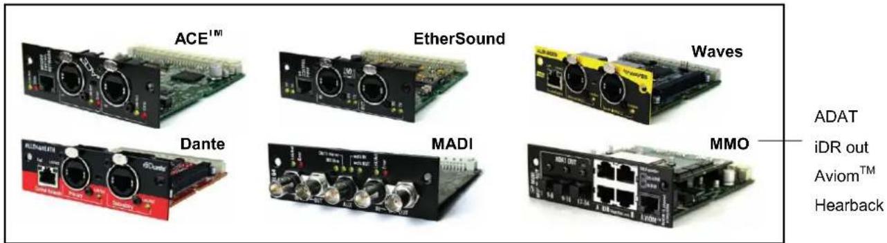
Up to 64 GLD inputs and 64 outputs can be assigned to an audio option card fitted to the GLD-80 rear panel I/O Port. The MMO (Mini Multi Out) card provides several output formats – 24 channels of ADAT optical out, two 8 channel iDR links to connect the Allen & Heath iDR-8 or iDR-4 mix processors, or the iDR-Out or iDR-Dout output expander, and also compatible with the HearBus hub, and a 16 channel output compatible with Aviom® A-Net 16 or the Allen & Heath ME personal mixing system running in Aviom mode.
The card uses 56 channels from the port. These are assigned using the I/O / Port Out screen. The port channels map to the MMO sockets as below:
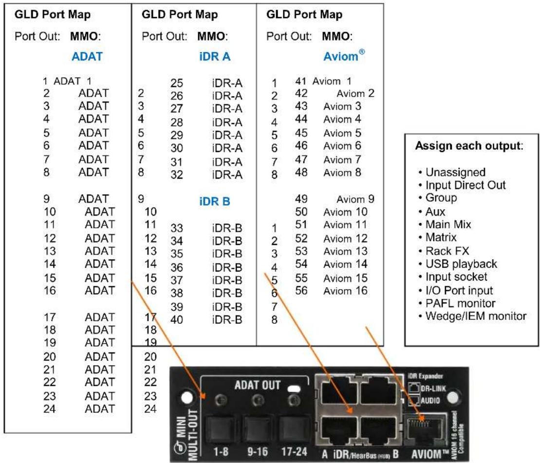
other
GLD Port Map Port Out: MMO: ADAT 1 ADAT 1 2 ADAT 3 ADAT 4 ADAT 5 ADAT 6 ADAT 7 ADAT 8 ADAT 9 ADAT 10 ADAT 11 ADAT 12 ADAT 13 ADAT 14 ADAT 15 ADAT 16 ADAT 17 ADAT 18 ADAT 19 ADAT 20 ADAT 21 ADAT 22 ADAT 23 ADAT 24 ADAT GLD Port Map Port Out: MMO: iDR A 25 iDR-A 26 iDR-A 27 iDR-A 28 iDR-A 29 iDR-A 30 iDR-A 31 iDR-A 32 iDR-A GLD Port Map Port Out: MMO: Aviom® 1 41 Aviom 1 2 42 Aviom 2 3 43 Aviom 3 4 44 Aviom 4 5 45 Aviom 5 6 46 Aviom 6 7 47 Aviom 7 8 48 Aviom 8 iDR B 49 Aviom 9 50 Aviom 10 51 Aviom 11 52 Aviom 12 53 Aviom 13 54 Aviom 14 55 Aviom 15 56 Aviom 16 ADAT OUT MINI MULTI-OUT A iDR/HearBus (min) B AVIOM™ AVIOM 16 channel Compatible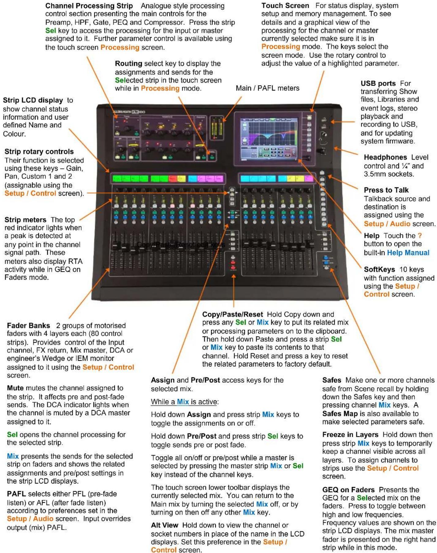
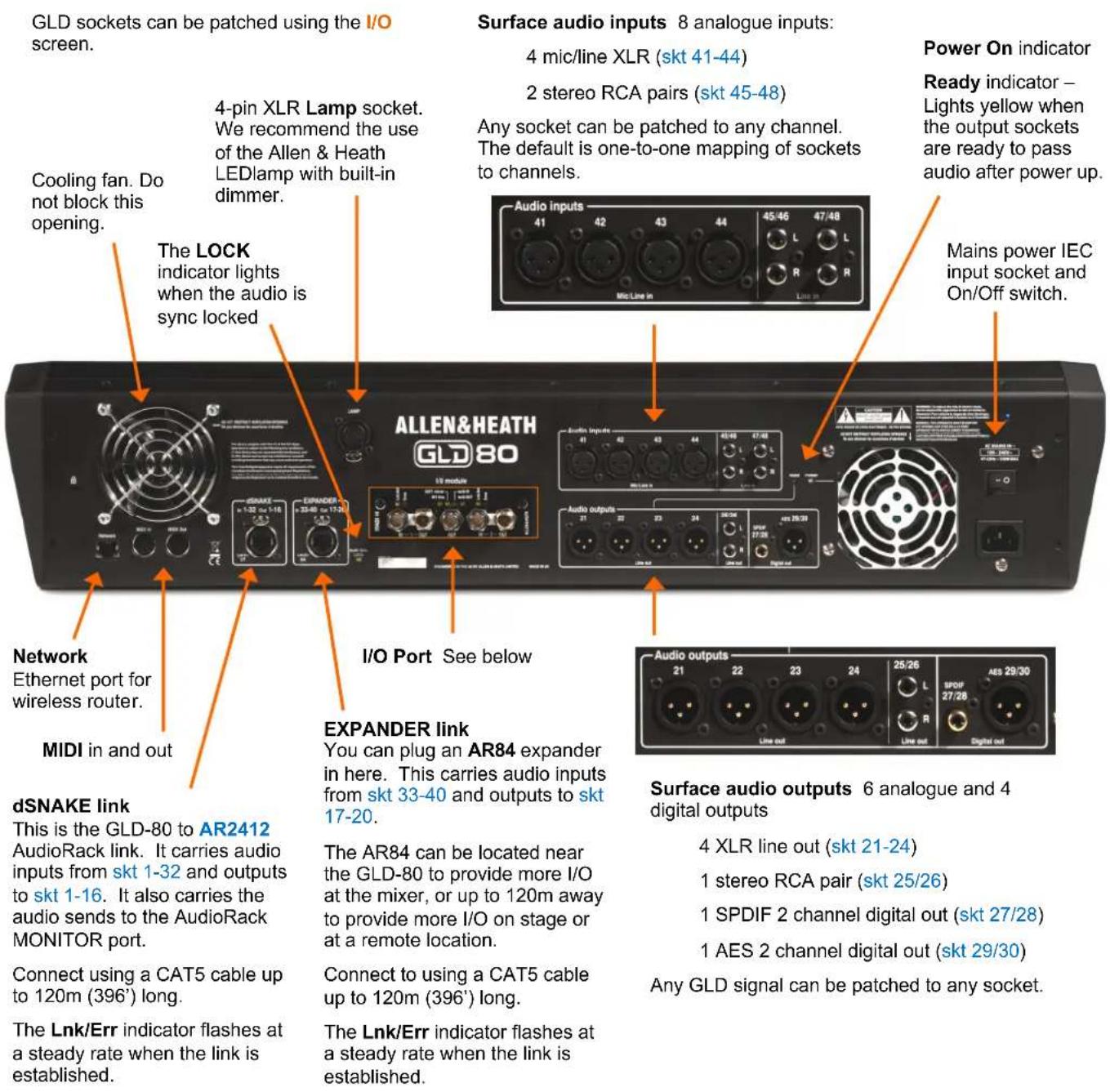
I/O Port options for system linking, expansion, recording and audio networking using one of the option cards available from Allen & Heath. 64 channel bi-directional 48kHz audio.
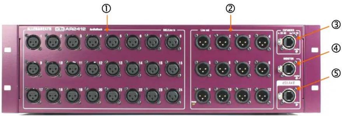
① Input sockets 24 balanced XLR inputs for microphone and line level sources. The preamps are built into the AR2412 rack and their Gain, Pad and 48V phantom power is remote controlled from the GLD console via the dSNAKE link. The output of the analogue preamps are converted to digital format and transported via dSNAKE to be processed and mixed at the GLD-80 mixer.
The sockets are numbered 1-24. Any input can be patched to any channel using the I/O or Preamp screens. The default is one-to-one mapping of the input sockets 1-24 to channels 1-24.
② Output sockets 12 balanced XLR outputs operating at nominal +4dBu line level. Any GLD signal can be patched to any socket using the console I/O screen. The default Template Shows provide a logical mapping of these sockets to get you started.
③ EXPANDER port CAT5 cable link to connect a GLD-AR84 expander rack to add a further 8 mic/line inputs and 4 XLR line outputs. The GLD system numbers these sockets as Inputs 25-32 and Outputs 13-16. This port can also be used to connect to the Allen & Heath ME personal mixing system.
④ MONITOR port CAT5 cable link to connect to the ME personal mixing system. It is also compatible with Aviom® A-Net 16 when Aviom mode is selected in the I/O / Monitor screen.
⑤ dSNAKE port CAT5 cable link to connect the AR2412 rack to the GLD-80 mixer. This carries the 32 inputs, 16 outputs and the monitor port sends audio to and from the rack as well as control for the preamps and system status.
Maximum CAT5 cable length is 120m (396') depending on cable type.
Note that dSNAKE is not compatible with the iLive ACE connection.
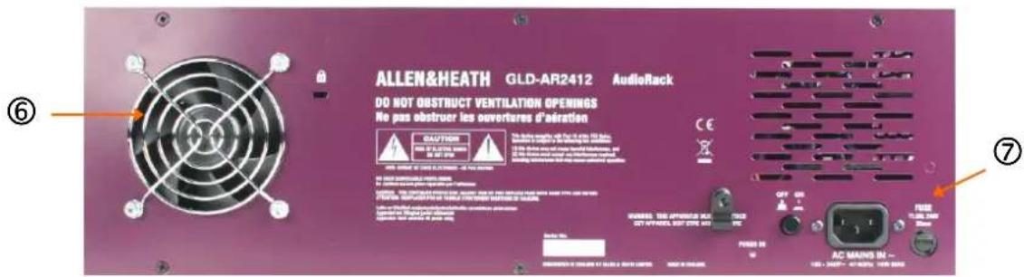
⑥ Fan A low noise fan ensures air movement through the rack to keep the circuits within operating temperature range.
- Ensure good ventilation at the back of the rack. Read the safety instructions printed on the panel and the Safety Sheet packed with the unit.
⑦ Mains power input IEC connector, fuse and power ON/OFF push switch for the built-in universal voltage power supply unit. This accepts worldwide voltages from 100 to 240V AC 50/60Hz. Check that you have received the correct mains lead for your territory.
Secure the cable in place using the plastic P-clip. Use a T20 Torx screwdriver to refit the screw.
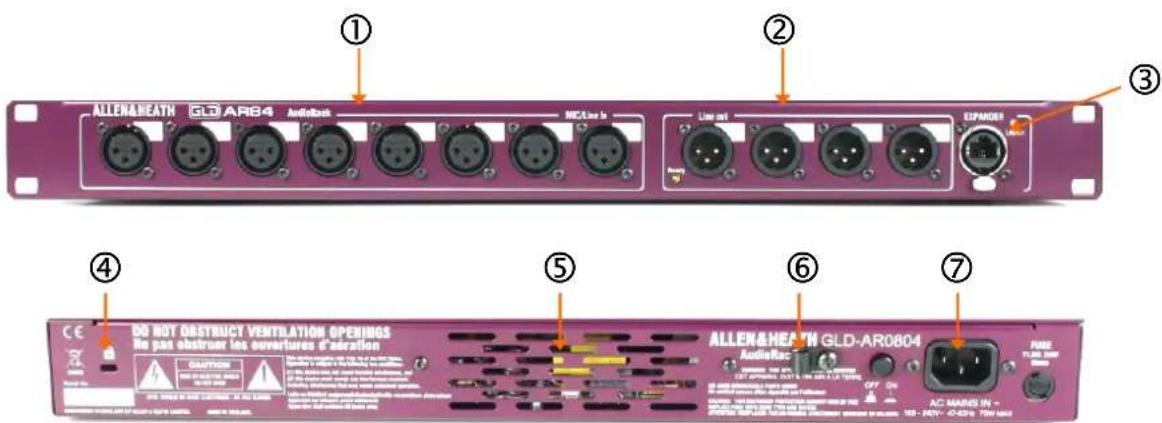
① Input sockets 8 balanced XLR inputs for microphone and line level sources. The preamps are built into the AR84 rack and their Gain, Pad and 48V phantom power is remote controlled from the GLD console via the EXPANDER link. The output of the analogue preamps are converted to digital format and transported via a Cat5 cable to be processed and mixed at the GLD-80 mixer.
Any input can be patched to any channel using the I/O or Preamp screens.
The sockets are not numbered. This is because the number depends on where the AR84 is plugged into the GLD system. Write-on blocks are provided for you to label the sockets.
② Output sockets 4 balanced XLR outputs operating at nominal +4dBu line level. Any GLD signal can be patched to any socket using the console I/O screen. The default Template Shows provide a logical mapping of these sockets to get you started.
The sockets are not numbered. This is because the number depends on where the AR84 is plugged into the GLD system. Write-on blocks are provided for you to label the sockets.
The socket identification is shown in the diagram below:
③ EXPANDER port CAT5 cable link to connect the AR84 expander to the EXPANDER port on the AR2412 AudioRack or GLD-80 Mixer.
Note that the EXPANDER link is not compatible with the iLive ACE connection.
④ Kensington security slot To attach a 'Kensington lock' standard anti-theft cable and lock if required.
⑤ Fan A low noise fan inside the rack ensures air movement to keep the circuits and internal components within operating temperature range.
- Ensure good ventilation at the back of the rack. Read the safety instructions printed on the panel and the Safety Sheet packed with the unit.
⑥ Mains cable clip You can secure the cable in place using the plastic P-clip. Use a T20 Torx screwdriver to refit the screw.
⑦ Mains power input IEC connector, fuse and power ON/OFF push switch for the built-in universal voltage power supply unit. This accepts worldwide voltages from 100 to 240V AC 50/60Hz. Check that you have received the correct mains lead for your territory.
Socket numbering
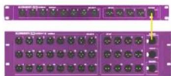
AR84 plugged into the AR2412 main AudioRack:
Inputs 25-32
Outputs 13-16
natural_image
Front and back view of a purple rack-mounted network device with multiple ports (no visible text or labels)AR84 plugged into the GLD-80 Mixer:
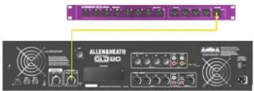
Inputs 33-40
Outputs
17-20
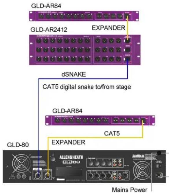
Connect the AR2412 AudioRack Plug a CAT5 cable into the dSNAKE port at the rack and mixer. This is the main system link.
Connect the AR84 AudioRacks Plug a CAT5 cable into the EXPANDER port of the AR84 and the EXPANDER port of the AR2412 or GLD-80 mixer.
● Always plug the AR84 into an EXPANDER port. Do not plug it into the dSNAKE port even if you are not using an AR2412 main rack.
Plug in the mains power leads supplied with the mixer and racks. Secure the leads by hooking them into the plastic clips. If required the leads can be locked into these clips. Use a T20 Torx (starhead) screwdriver to remove the fixing screw.
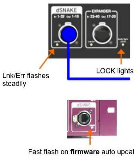
To turn on the system Turn on power using the rear panel On/Off switches.
The GLD-80 takes around 40 seconds to boot up. Its screen lights white for a few seconds, then turns black displaying its boot sequence. A while later the Home screen is displayed. At this point the yellow Lnk/Err indicators of connected dSNAKE and EXPANDER ports start to flash steadily showing that the link between the mixer and racks is established. The mixer Audio Sync LOCK indicator lights. Finally, the AudioRack Ready indicators light and you will hear a click as the output socket protection relays switch over.
- If the firmware in a connected AudioRack is not the same version as that in the GLD-80 then the mixer will automatically update the rack firmware during power up. This takes a few seconds. During this time the Lnk/Err indicators on the AudioRack flash at a fast rate. Once updated normal flash rate is restored.
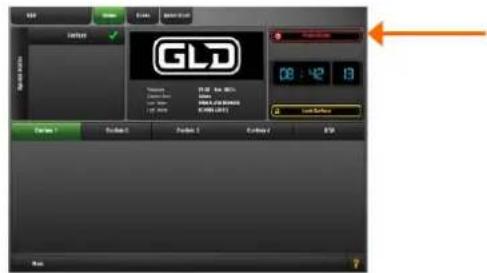
To turn off the system The system must be powered down correctly. Return to the Home screen. To do this turn off any active Sel key whilst in the Processing view.
Touch the Power Down button. A popup appears. Confirm the action then turn the mixer and racks off using their power switches.
- If the system is not powered down correctly there is a possibility recent changes may be lost.
- If the system was not powered down as described above then a 'Not shut down correctly' screen appears the next time the system is turned on.
GLD Remote iPad app and wireless router
GLD firmware Version 1.1 onwards supports the GLD Remote iPad app for wireless control of mixing and processing using one or more iPads. This allows simultaneous control of different functions by more than one engineer. For example, one engineer controlling the FOH mix at the GLD surface and another controlling monitors on stage using an iPad.
The router:
• Good wireless range
• Dual band (2.4 and 5GHz)
- Auto channel select
- Adjustable antennas
- Good security
Get the app Download the GLD Remote app from the Apple Store. You can open it in Demo mode without a GLD connected to get a feel for how it operates and to read the ? Help Manual within the app.
Choose a router (wireless access point) GLD Remote is a professional mixing tool that justifies network equipment of suitably high performance, quality and reliability.
For best performance we recommend you choose a dual band wireless router with auto channel selection. Use the more recent 5GHz band in places where there is intense WiFi activity or interference in the more crowded 2.4GHz band. A wireless router with auto channel selection automatically sets itself to an available or least congested channel when you power it up.
Refer to the Allen & Heath web site for more information on choosing wireless routers for use with the Allen & Heath iLive and GLD systems.
Recommended settings:
GLD (default)
Static IP = 192.168.1.50
Subnet Mask = 255.255.255.0
Router
Router IP = 192.168.1.254
Subnet Mask = 255.255.255.0
DHCP 192.168.1.100 to 200
Security = WPA
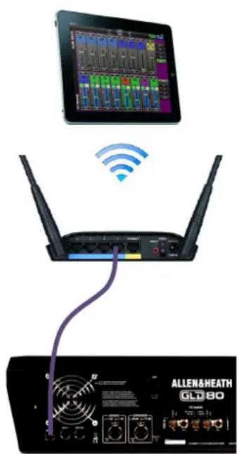
Set up the router You will need to connect it to a PC using a wired LAN connection. Follow the instructions provided by the wireless router manufacturer to access its setup menus.
Set the router IP address - This must be compatible with the GLD console which has a default static IP address = 192.168.1.50 and Subnet Mask = 255.255.255.0. Go to the Setup / Config / Network screen to check the current GLD settings.
To work with the GLD you must give your wireless router a unique but compatible IP address. Some routers may have a default address that is not compatible and must be changed, for example 192.168.2.1. Some may already be compatible, for example 192.168.1.254.
Set the router DHCP settings - Make sure the router is set for DHCP so that it automatically allocates a compatible IP address to your iPad. To avoid conflict with the GLD static address we recommend you set a router DHCP address allocation range of 192.168.1.100 to 200.
Note You do not need to change the GLD setting to DHCP. The console will work fine with a static IP address as long as it is not within the router DHCP address range.
Set the router security -To prevent other people accessing your Wi-Fi we recommend you enable WPA/WPA2 encryption during router setup. A wireless key (password) will need to be set up.
Make a note of the router SSID. This is the name that the router broadcasts to help identify it in the network list you will see in the iPad Settings Wi-Fi page. If you want you can change the SSID to help you identify it alongside other wireless networks in the area.
After setup, the wireless router can be connected to the Network socket on the rear of the GLD console using a CAT 5 cable. Plug this into one of the LAN (not Internet) ports on the rear of the router.
Position the router Make sure it is within the specified range and in line of sight of the iPad where possible. It can help to place it high up to avoid obstacles such as people and equipment. Avoid locating it behind pillars or walls, near metal beams or on top of loudspeakers.
Recall a 'Template Show' as a starting point
The GLD has a fully configurable audio architecture, control layout and socket patching letting you customise the way you work. It would be a daunting task for the new user if we gave them a 'blank canvas' to start from scratch. Instead we have provided a set of 'Template' Show memories which give you a choice of classic console format to load in as a quick starting point. These present the familiar architecture and logical layout of well equipped analogue consoles.
Once you are comfortable working with GLD you can make changes to your set up and save these as your own 'User' Shows. These let you archive and recall the complete configuration and setup. Use Scenes for instant store and recall of band sound checks, theatre cues and different event settings. Scenes are stored within the Show.
A Show memory stores the complete GLD setup. This includes:
- Current settings
- Mix configuration
- User preferences
• All Scene memories - All Libraries
A default show is already loaded when the GLD is shipped from the factory. This is Template1 LR. You can load a different Template as your starting point if you wish:
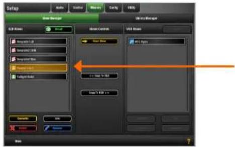
To load a Template Show Go to the Setup / Memory / Show Manager screen. Available Shows are listed. These include Template and User Shows.
Touch the Template Show you want to load. Touch Recall. A popup appears for you to confirm the action.
- Recalling a Show overwrites all the system settings including the DSP mix architecture, Surface configuration, current parameters, all the Scene and Library memories. If you want to keep the current settings to be used again in the future then first Store them as a User Show.
The Show Manager screen
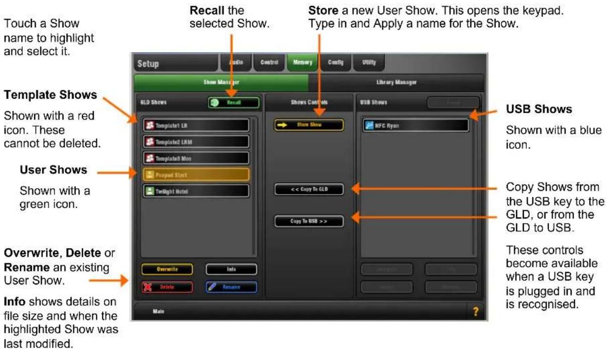
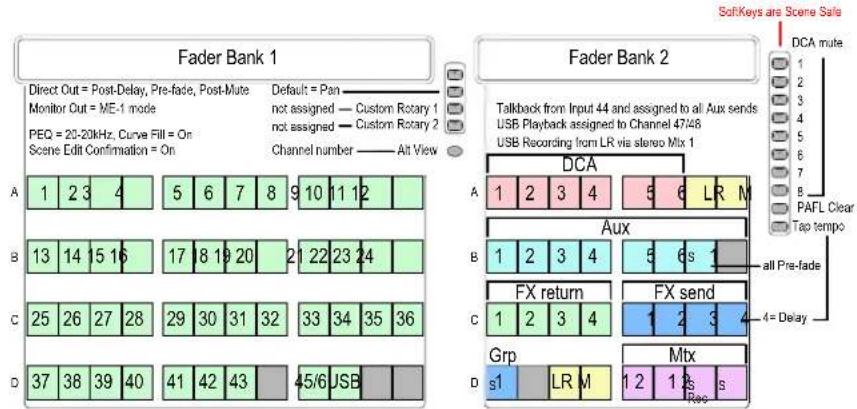
There are three Template Shows available. These have the following settings:
- SoftKey assignments are Scene Safe
- SoftKeys 1-8 = DCA mute 1-8
- SoftKey 9 = PAFL Clear All
- SoftKey 10 = FX4 tap tempo (FOH only)
- Scene Confirmation = On
• Global Direct Out = post-delay, pre-fade, post-mute
• Monitor Port = ME-1 mode
• I/O Port out = input socket 1-48
• PEQ = 20-20kHz, Curve Fill = On - Auxes are post-PEQ, pre-fade (monitors)
• FX are post-fade (effects)
• USB playback assigned to CH47/48
• USB recording from LR via stereo Matrix1
The Template Show 'Board Reset' Scene Each Template Show provides a Scene called 'Board Reset'. This resets the GLD settings to the starting point default for the loaded Template Show. The Board Reset Scene is available in position 1 and duplicated in position 500 for backup.
Use this Scene to instantly reset parameters without affecting the mix configuration, user preferences or the other Scenes. You can edit its Recall Filter to protect parameters you do not wish to reset. For example, you could set the filter to protect the patchbay and master strip assignments in a festival situation.
Note You can also set Scene Safes to protect selected parameters for all Scenes, for example to remove the SoftKeys from Scene recall.
When creating your own User Show from a Template Show you can choose to overwrite the Scene 1 contents with your preferred settings, rename it, write in a description, set its Recall Filter to reset selected parameters, or simply delete it. You can still access the default Board Reset using Scene 500 if needed.
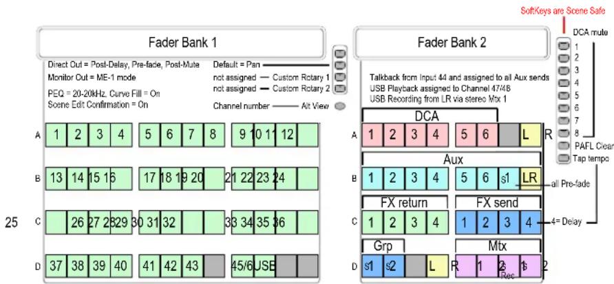
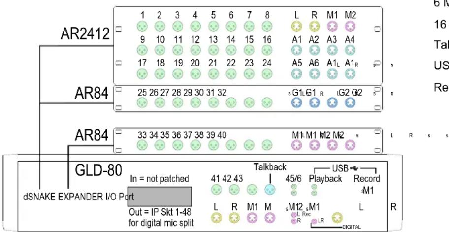
Template1 LR
This Template configures a traditional architecture and layout with stereo LR main mix for mixing FOH and Monitors from FOH:
LR stereo main mix
4 Groups (2 stereo)
8 Auxes (6 mono, 1 stereo)
8 FX (4 assigned to strips)
6 Matrix (2 mono, 2 stereo)
16 DCA / Mute groups
Talkback using mic socket 44
USB playback to CH47/48
Recording from stereo Matrix 1
Template2 LRM (also use for LCR)
This Template configures stereo LR plus Mono bus for working with a 3-way FOH mix.
You can change the type of 3-way Main mix from LR+M (switched bus) to LR+M (mono sum of LR) or LCR using the Setup / Config / Mixer Config screen.
LR + Mono (switched bus) main mix
2 Groups (1 stereo)
8 Auxes (6 mono, 1 stereo)
8 FX (4 assigned to strips)
6 Matrix (2 mono, 2 stereo)
16 DCA / Mute groups
Talkback using mic socket 44
USB playback to CH47/48
Recording from stereo Matrix 1
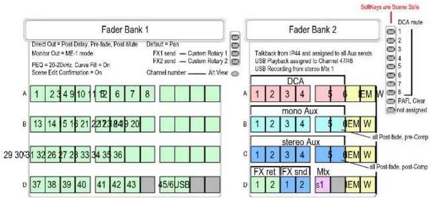
Template3 Mon
This Template configures the GLD as a dedicated monitor console with 18 mixes:
6 mono mixes (wedges, fills)
6 stereo mixes (IEM)
Auto switching engineer's Wedge/IEM
8 FX (2 assigned to strips)
Talkback using mic socket 44
USB playback to CH47/48
Recording from stereo Matrix 1
The engineer's IEM/Wedge monitor is configured so that pressing a mono Aux (wedge) mix PAFL key will automatically mute the engineer's stereo IEM monitor. Pressing a stereo Aux (IEM) mix PAFL key will mute the engineer's Wedge monitor.
A few things to know before starting
Before working with the GLD familiarise yourself with its control layout and operating principles.
The Touch Screen
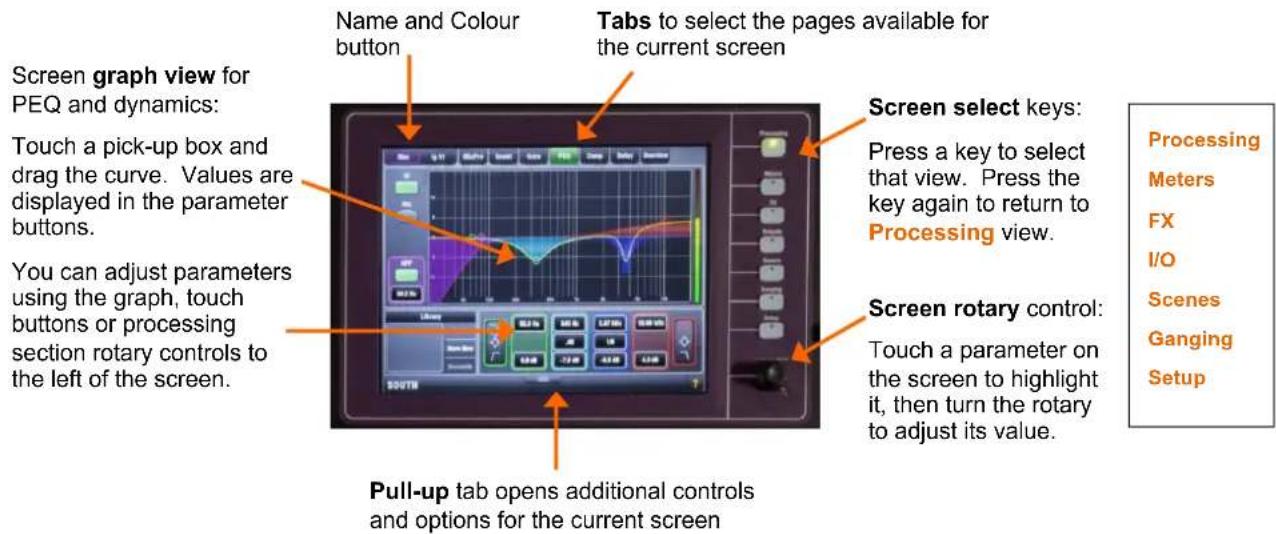
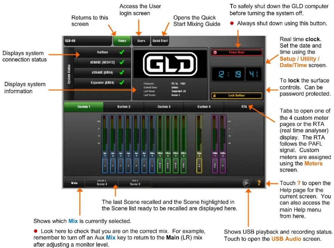
The Home Screen
This screen displays after power up. You can return here by turning off any active strip Sel key while in the screen Processing view. You can also do this by turning on, then off any strip Sel key.
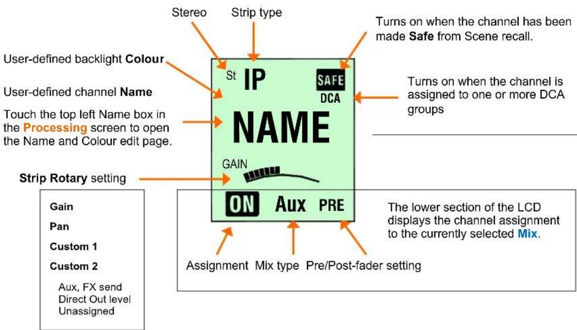
The strip LCD display
The LCD strip above the faders displays information about the channels assigned to the faders. Channels can each be named and have one of 8 backlight colours applied. You can edit these names and colours to easily identify different channel and mix types, or highlight certain instruments and sources.

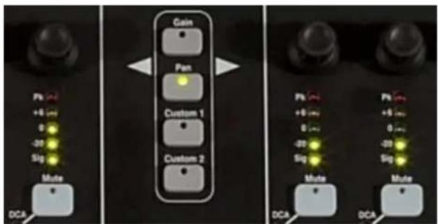
Select the function of the strip Rotary controls using these keys. The Custom keys are assigned using the Setup / Control / Surface Prefs screen.
- Check that you have selected the correct function when working with the rotary controls.
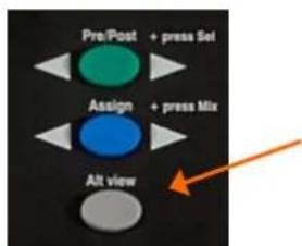
Press and hold the Alt View key to see the Channel Number, Socket Number or fader dB value in place of the Name in the LCD display.
Choose the Alt View function using the Setup / Control / Surface Prefs screen.
The Fader Banks
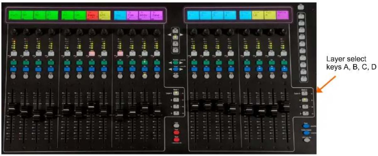
There are 2 independent Fader Banks, one with 12 fader strips, the other with 8 fader strips. Each Bank has 4 Layers. This means that the GLD-80 can work with up to 80 fader control strips.
Any strip can be assigned as an Input channel, Mix master, FX send master, FX Return, engineer's Wedge or IEM master, or DCA master in any combination. Strips can be left blank (unassigned). The Template Shows provide a logical assignment of the fader strips to give you a familiar starting point.
To change the fader strip assignment use the Setup / Control / Strip Assignment screen. You can drag-and-drop to quickly reassign the strips.
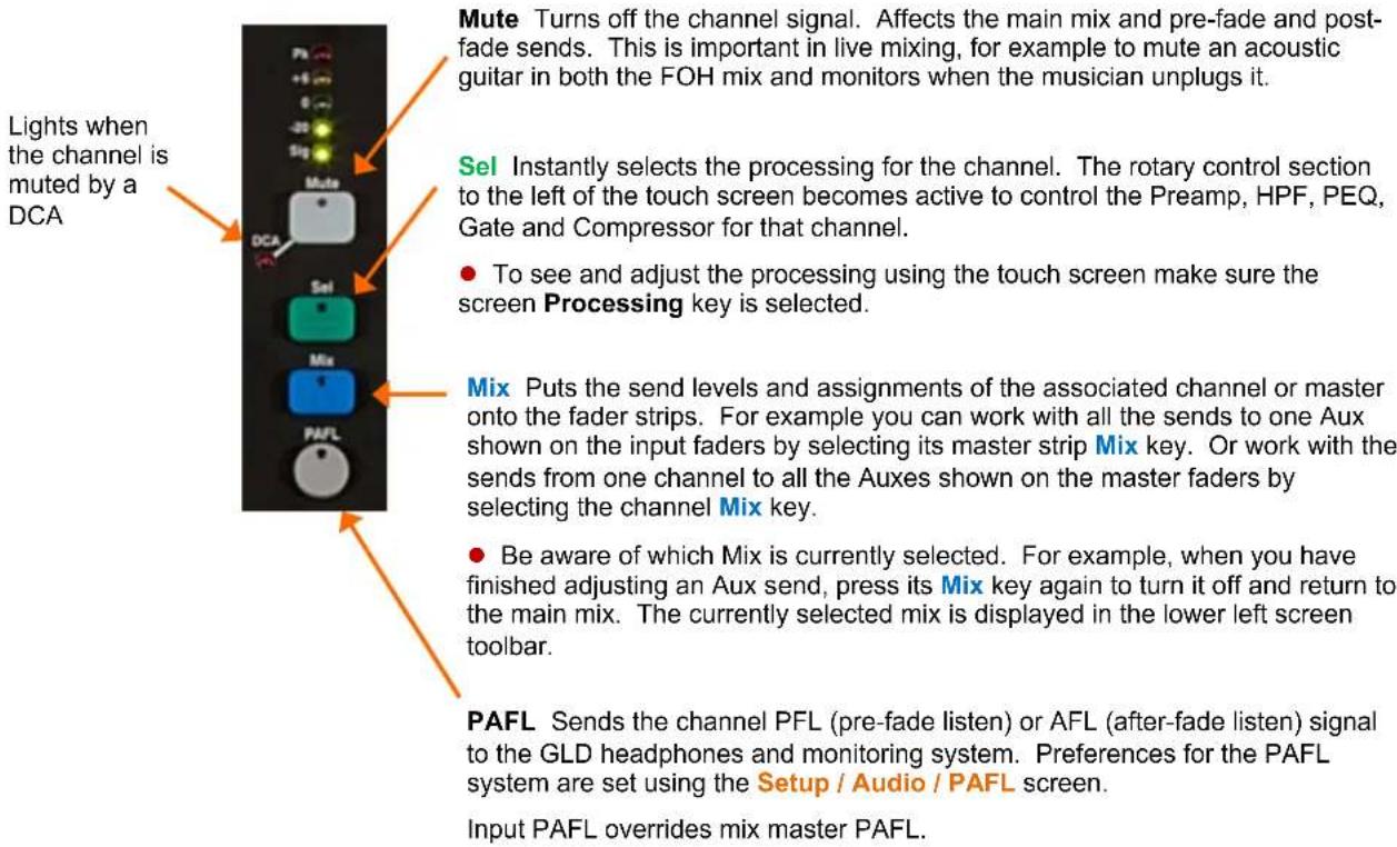
The Fader Strip keys
4 keys per strip provide quick access to important live mixing functions:
Working with the Mix on the fader strips
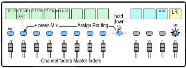
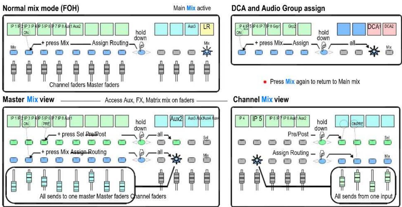
Normal mix mode (FOH)
Main Mix active
flowchart
graph TD
    A["IP 1 IP 2 IP 3 IP"] --> B["ON"]
    C["IP 5 IP 6"] --> D["+ press Mix"]
    E["IP 7 IP 8 Aux1"] --> F["Assign Routing"]
    G["Aux2"] --> H["load down"]
    I["Aux3"] --> J["LR"]
    K["Mix"] --> L["Channel faders Master faders"]
    M["Mix"] --> N["Channel faders Master faders"]
Press a Main Mix master strip Mix key.
This is the normal mixing mode. The Input strips present the channel faders. The Master strips present the master mix faders.
Hold down the Assign key and press channel Mix keys to assign or de-assign them from the main mix. Current ON status is displayed on the lower part of the strip LCDs.
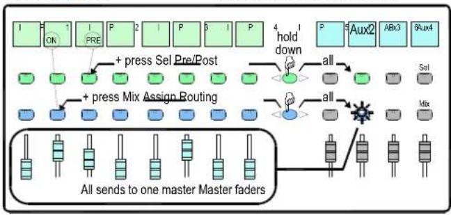
Master Mix view
Access Aux, FX, Matrix mix on faders
flowchart
graph TD
    A["Channel 1 ON"] --> B["Channel 2 PRE"]
    B --> C["Channel 3 P"]
    C --> D["Channel 4 S"]
    D --> E["Channel 5 P"]
    E --> F["Aux2"]
    F --> G["Channel 6 Abx3"]
    G --> H["Channel 7 Au4"]
    I["+ press Sel Pre/Post"] --> J["+ press Mix Assign Routing"]
    J --> K["All sends to one master Master faders"]
    L["hold down"] --> M["all"]
    N["all"] --> O["Power Supply"]
    P["All"] --> Q["Switch Signal"]
Press a Mix master strip Mix key.
^7 Use this to work with Aux and FX sends. The Input strips change to present all the send levels to the selected mix. The Master strips present the master mix faders.
Hold down the Assign key and press channel Mix keys to assign or de-assign them from the selected mix.
Hold down the Pre/Post key and press channel Sel keys to toggle each source pre or post fader. Current PRE status is displayed on the lower part of the channel strip LCDs.
You can quickly set all assignments on or off, or all sources pre or post fader by pressing the Master strip Mix or Sel key instead of a channel key as described above.
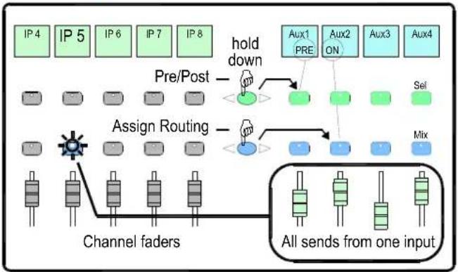
Channel Mix view
flowchart
graph TD
    A["IP 4"] --> B["Pre/Post"]
    C["IP 5"] --> B
    D["IP 6"] --> B
    E["IP 7"] --> B
    F["IP 8"] --> G["Hold down"]
    H["Aux1 PRE"] --> I["Switch"]
    J["Aux2 ON"] --> I
    K["Aux3"] --> I
    L["Aux4"] --> I
    M["Sel"] --> I
    N["Assign Routing"] --> O["Switch"]
    P["Mix"] --> O
    Q["Channel faders"] --> R["Switch"]
    S["All sends from one input"] --> T["Switch"]
Press an Input Channel strip Mix key.
Use this to work with Aux and FX sends. The Input strips remain as Channel Faders. The Master strips change to present all sends from the selected channel.
Hold down the Assign key and press master Mix keys to assign or de-assign the channel from each mix.
Hold down the Pre/Post key and press master Sel keys to toggle the channel pre or post fader to each mix. Current status is displayed on the master strip LCDs.
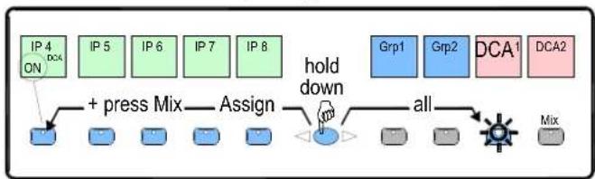
DCA and Audio Group assign
flowchart
graph LR
    A["IP 4 ON"] --> B["+ press Mix"]
    B --> C["Assign"]
    C --> D["hold down"]
    D --> E["all"]
    E --> F["Grp1"]
    E --> G["Grp2"]
    E --> H["DCA1"]
    E --> I["DCA2"]
    J["Mix"] --> K["Gray Box"]
Press a Group Master strip Mix key.
Use this to assign channels to the Audio and DCA groups. The Input and Master faders are not affected.
Hold down the Assign key and press channel Mix keys to assign or de-assign the channels from the group.
Working with Scenes
GLD has 500 Scene memories. These are 'snapshots' of the live mixing parameters. They store all current mix settings but not the bus configuration and user preferences. Use Scenes to store parameter changes you want to recall instantly, for example cues during a theatre production or sound checked bands during a music show. Use Shows to store and archive the complete GLD setup including its bus configuration, user preferences and all Scene memories.
A Scene stores all parameter settings. A Recall Filter is available for each Scene to let you choose which parameters to recall. For example, work with just the channel fader levels and mutes for a range of Scenes, or change an EQ on one channel using a Scene. You can name Scenes, add a description, copy and paste their settings to other Scenes, delete their contents, and create Cue Lists from selected Scenes arranged in any order and repeated any number of times.
Global Scene Safes can be set to protect selected parameters being overwritten by the Scene system. These can be set using the Scene Safes screen. You can also fully protect a channel or master from Scene recall by pressing the Safes key together its strip Mix key. For example, to protect background music and continuity announcement while a band sound check is recalled.
Refer to the GLD Touch Screen Reference Guide for more information on using Scenes and the other functions accessed via the screen.

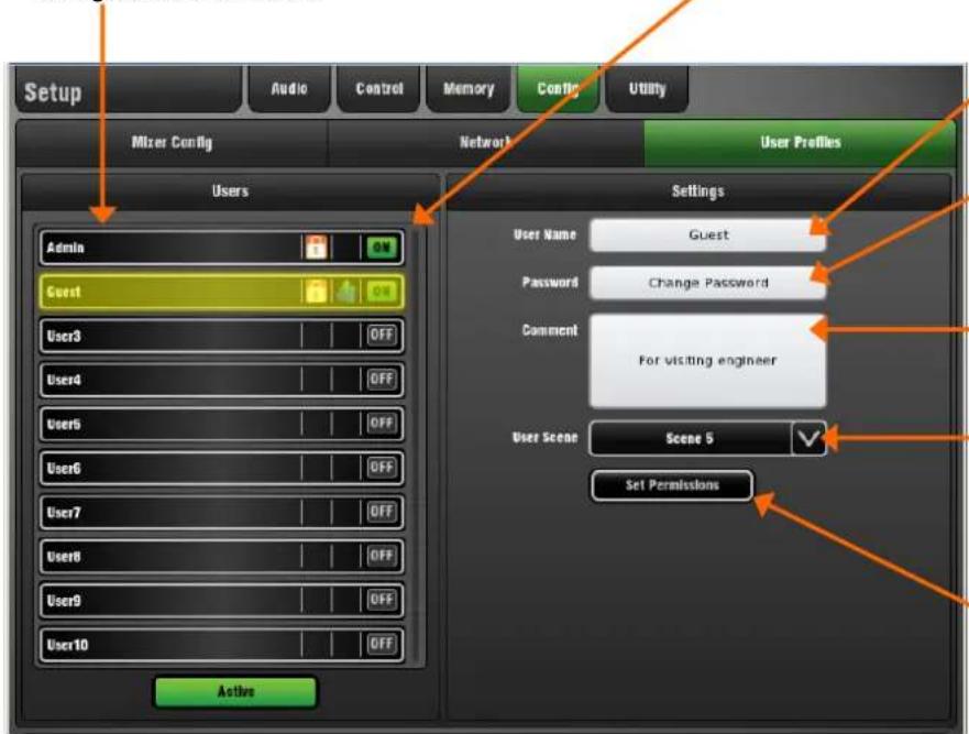
GLD lets you set up and work with up to 10 'User Profiles' including an Administrator and 9 Users. You can set permissions and a password to restrict operator access to certain functions.
The User List. 'Admin' has access to all functions and can set permissions and allocate passwords if required for the other users. Up to 9 guest users may be configured and activated.
Icons show if a User is ON (active), has a password set, or has a User Scene set.
Refer to the GLD Touch Screen Reference Guide for more information on using User Profiles and setting their Permissions.
Touch to open the keypad and Apply a name for the selected User.
Touch to set or change the password. This is entered twice to avoid errors.
You can add a comment to display here and on the Login screen. For example, provide details about or instructions for each user.
You can choose a User Scene which will recall when a different user with a Scene set logs in. This does not recall when the same user logs in. Choose 'No Scene' if none is required.
Touch to open the Set Permissions page. Here you can enable or disable any combination of functions to restrict how much control and access you give each User.
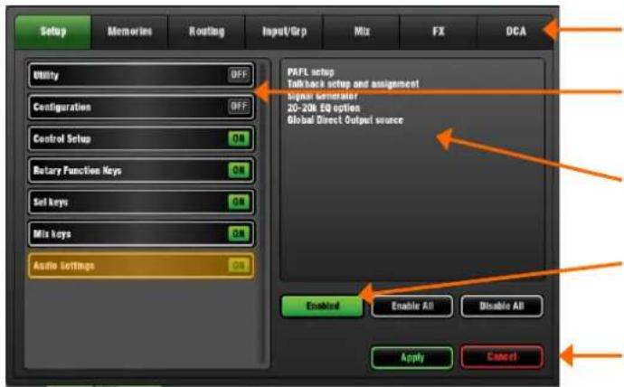
Category tabs group the different types of user permissions available.
List of permissions for the selected category show if they are enabled (ON) or disabled (OFF).
A description of the parameters affected for the highlighted permission is shown here.
Touch to enable or disable the highlighted permission.
Touch Apply to save your changes or Cancel to return to the User Profile page without saving.
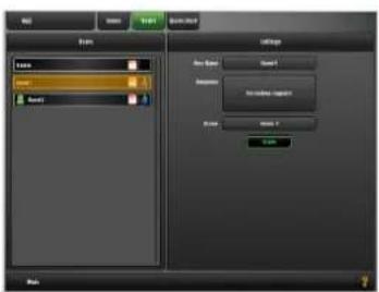
To log in as a different user Go to the Home / Users screen and select a User. Touch Login. The User can also be changed from the GLD power up Login screen which appears when a password is set for the current user.
If a password has been set then you are prompted to enter it when you log in, turn the system on, or lock and unlock the Surface.
If a User Scene has been set then this will be recalled, but only if you are logging in as a different user.
Play back stereo audio tracks from a USB key and record any pair of GLD sources on to the key.
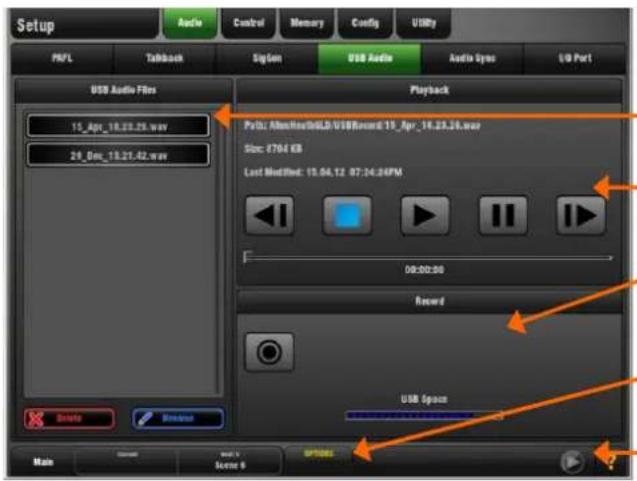
Audio file list shows the tracks available to play back.
Playback controls and information about the currently selected track.
Recording control to start/stop the recording. Opens the screen keypad to apply a name before the recording starts.
OPTIONS pull-up to choose which audio files to show in the list and select single, repeat or continuous playback.
Playback/Recording status shown here. You can touch this while in any screen to open the USB Audio screen.
Playback - The GLD can play back stereo MP3, WAV, M4a or FLAC files at 44.1 or 48kHz.
To assign USB playback to an Input Channel – Patch USB Playback to input channels using the I/O / Surface screen or the channel Preamp screen. USB playback is assigned to Ch 47/48 in the factory Template Shows.
To select a track to play back - Plug in a USB key with the audio files you wish to play back. Set the OPTIONS in the pull-up. Scroll through the list and touch to highlight a track. Information on the track including file path, size and date is displayed.
To start the playback - Use the transport buttons to Play, Pause, Stop and select Next or Previous track. A blue arrow in the lower toolbar in all screens shows a track is playing.
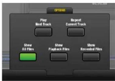
Open the OPTIONS pull-up to set playback options:
Play Next Track - Single or continuous playback.
Repeat Current Track - Continuously play a single track,
Show All Files – List all audio files in all directories found on the USB key,
Show Playback Files – List audio files found in the USBPlayback sub directory only.
Show Recorded Files –List audio files found in the USBRecord sub directory only.
Recording - Format = WAV files at 48kHz.
Recording time - Maximum recommended recording time for one track = 3 hours. Memory required = 188KB/sec. Therefore allow:
To assign a recording source – Use the IO / Surface screen. For example, record the main mix, a stereo group, aux or matrix, or two independent mono signals. USB recording is fed from Stereo Matrix1 in the factory Template Shows.
Check recording level – If you are using a source other than the Main mix, for example a stereo Matrix, then check that the send level to the source and its master fader are turned up. Check that there is signal displayed on the source meter.
To start the recording - Touch the Record button. This opens the name keypad. The default date/time name can be overwritten using the keypad. Default example = 15_Apr_18.23.26.wav
Touch Apply to start the recording. The elapsed time and remaining time available on the USB key is shown. A red circle in the status bar in all screens indicates that the GLD is recording to the key.
To stop the recording – Touch the Record button again.
USB Folders
The AllenHeathGLD / USBRecord directory is automatically created on your USB key when you start a recording.
The AllenHeathGLD / USBPlayback directory is automatically created when you select the Show Playback Files pull-up option. Or you can create it manually using your computer and add the files you wish to play back.
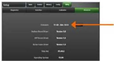
Go to the Setup / Utility / Firmware screen to check the current firmware version of running on the GLD. Go to www.allen-heath.com to check the latest version of GLD firmware available for download.
We recommend you check the Allen & Heath web site regularly and keep your console updated with the latest firmware.
Note 1: Use a USB key with at least 40 MB of free space. Delete any existing GLD Firmware on the key as described below.
Note 2: The firmware file transfer must not be interrupted. Failure to complete the transfer may result in firmware corruption of the GLD. Make sure the mains power and connecting cables are reliable and that the system will not be disturbed or switched off during the update.
Note 3: Updating firmware restores the console parameters to factory default. If you want to keep your current settings then go to the Setup / Memory / Show Manager screen and store them as a Show memory before starting the update. Recall the show after you have updated your firmware.
Note 4: After updating the firmware you may need to re-calibrate the touch screen and faders. Do this using the Setup / Utility / Calibration screen.
Firmware update instructions for Windows:
Step1 Download the firmware
Visit www.allen-heath.com and download the latest GLD firmware. Save the zipped file to your Desktop or folder of your choice. You may also wish to keep a copy of this zip file as a backup of this version of firmware.
Step2 Remove any previous GLD Firmware from your USB key
Plug a USB key into your computer. If you have previous GLD firmware already on your key, look in its AllenHeathGLD folder and delete the existing Firmware directory and also the Firmware.md5 file in the AllenHeathGLD folder. Do not delete the other directories.
Step3 Open and extract the Zip file to your USB key
Open up the zip file you have just downloaded. Extract all files to the root directory of your USB key. Once the extraction is complete check that a new Firmware directory has appeared under the AllenHeathGLD folder on your USB key. You may need to refresh the AllenHeathGLD folder to see this.
Note: Do not change the folder name or browse inside the Firmware folder as doing this may cause firmware corruption. Attempting to navigate or open files within this directory may cause your Operating System to leave behind temporary files which can invalidate your firmware.
Step4 Safely remove the USB key from your computer
Click on the 'safely remove hardware' icon, in the bottom right of your screen to safely remove your USB key.
Step5 Plug the key into a USB port on the GLD
Plug your USB key into either one of the USB ports on the GLD-80. Go to the Setup / Utility / Firmware screen and touch Update. This will then detect your USB key and validate the firmware contents.
Step6 Perform the update
Touch the Update button. Do not interrupt this process. When the firmware has been successfully installed, touch the Reboot button. The GLD will reboot with the new firmware installed. Any AudioRacks currently connected or connected later to the GLD-80 will have their firmware automatically updated by the GLD-80 during their boot process.
Step7 Recall your settings
Recall a Template Show or the User Show you saved before the update to restore your settings.
Firmware update instructions for Mac:
Step1 Download the firmware
Visit www.allen-heath.com and download the latest GLD firmware. Save the zipped file to your Desktop or folder of your choice. You may also wish to keep a copy of this zip file as a backup of this version of firmware.
Step2 Remove any previous GLD Firmware from your USB key
Plug a USB key into your computer. If you have previous GLD firmware already on your key, look in its AllenHeathGLD folder and delete the existing Firmware directory and also the Firmware.md5 file in the AllenHeathGLD folder. Do not delete the other directories.
Step3 Extract the Zip file and copy the folder to your USB key
Navigate to where you have saved the GLD firmware zip file. Double click on the zip file to extract its contents (this may have automatically been done for you). You will now see a folder called AllenHeathGLD. Copy this folder to the root directory of the USB key.
Check that a new Firmware directory has appeared under the AllenHeathGLD folder on your USB key. You may need to refresh the folder to see this.
Note: Do not change the folder name or browse inside the Firmware folder as doing this may cause firmware corruption. Attempting to navigate or open files within this directory may cause your Operating System to leave behind small temporary system files which can invalidate your firmware.
Step4 Eject the USB key from your computer
You can do this by clicking on the small eject icon by the USB key in Finder.
Step5 Plug the key into a USB port on the GLD
Plug your USB key into either one of the USB ports on the GLD-80. Go to the Setup / Utility / Firmware screen and touch Update. This will then detect your USB key and validate the firmware contents.
Step6 Perform the update
Touch the Update button. Do not interrupt this process. When the firmware has been successfully installed, touch the Reboot button. The GLD will reboot with the new firmware installed. Any AudioRacks currently connected or connected later to the GLD-80 will have their firmware automatically updated by the GLD-80 during their boot process.
Step7 Recall your settings
Recall a Template Show or the User Show you saved before the update to restore your settings.
USB directory structure
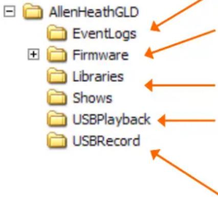
The AllenHeathGLD folder is located in the root directory of your USB key.
Event Logs are copied to this directory. You can email them to Allen & Heath Tech Support if they require further investigation.
Delete the Firmware directory as described in Step 2 above before unzipping a new version of firmware to your key. Do not browse this directory as opening files may result in the firmware failing to update.
The GLD uses these directories to store the parameter Libraries and User Shows.
GLD creates this folder when you open the Setup / Audio / USB Audio screen Options pull-up and choose the 'Show Playback Files' option. Create this directory if it does not already exist and copy audio files from your computer here to view and play selected files rather than all audio on your USB key.
GLD creates this directory to store audio recordings.
Inputs
| XLR Mic/Line Inputs | Balanced, (All XLR on GLD-80 and AudioRacks) |
| Mic/Line Preamp | Fully recallable |
| Input Sensitivity | -60 to +15dBu |
| Analogue Gain | +5 to +60dB, 1dB steps |
| Pad-20dB | |
| Maximum Input Level | +32dBu |
| Input Impedance | >4kΩ (Pad out), >10kΩ (Pad in) |
| Mic/Line Channel noise | 20-20kHz, Direct Out @ unbalanced out |
| Mic EIN | -127dB with 150Ω source |
| Unity gain (Pad in) | -90dBu |
| Low gain (5dB, Pad out) | -93dBu |
| Mid gain (30dB, Pad out) | -89dBu |
| Mic/Line Channel THD+N | 20-20kHz, Direct Out @ unbalanced out |
| Unity gain (Pad in) | 0.005% -86dBu @ 1kHz, 0dBu output |
| Low gain (5dB, Pad out) | 0.003% -89dBu @ 1kHz, 0dBu output |
| Mid gain (30dB, Pad out) | 0.004% -88dBu @ 1kHz, 0dBu output |
| RCA Line Inputs | Unbalanced (GLD-80) |
| Input Sensitivity | -24 to +24dBu, nominal 0dBu |
| Trim | +/-24dB, recallable |
| Maximum Input Level | +18dBu |
| Input Impedance | >10kΩ |
| RCA channel Noise | -92dBu 20-20kHz |
| RCA channel THD+N | 0.0035% -90dBu @ 1kHz, 0dB |
Outputs
| XLR Outputs | Balanced, Relay protected |
| Output Impedance | <75Ω |
| Nominal Output | +4dBu = 0dB meter reading |
| Maximum Output Level | +22dBu |
| Residual Output Noise | -91dBu (muted, 20-20kHz) |
| RCA Line Outputs | Balanced, Relay protected |
| Output Impedance | <75Ω |
| Nominal Output | 0dBu = 0dB meter reading |
| Maximum Output Level | +18dBu |
| Residual Output Noise | -94dBu (muted, 20-20kHz) |
| Digital Outputs | 48kHz sampling rate |
| SPDIF | RCA, 600mV, coax terminated input 75Ω |
| AES3 2 ch XLR output | XLR, 2.5Vpp balanced terminated 110 Ω |
System
| Measured balanced XLR in to XLR out, 20-20kHz, minimum Gain, Pad out | |
| Dynamic Range | 112dB |
| System Signal to Noise | -90dB |
| Frequency Response | 0/-0.25dB @ 20Hz, 0/-0.5dB @ 20kHz |
| System peak level THD+N | 0.0055% -68dBu @ +17dBu output, 1kHz |
| System Line level THD+N | 0.0022%, -84dBu @ +9dBu output, 1kHz |
| Headroom | +18dB |
| Internal operating Level | 0dBu |
| dBFS Alignment | +18dBu = 0dBFS (+22dBu at XLR output) |
| Meter Calibration | 0dB meter = -18dBFS (+4dBu at XLR out) |
| Meter Peak indication | -3dBFS (+19dBu at XLR out) |
| Meter Type | Fast (peak) response |
| Sampling Rate | 48kHz +/-100PPM |
| ADC | 24-bit Delta-Sigma |
| DAC | 24-bit Delta-Sigma |
| Latency | 1.49ms (GLD-80 local XLR in to XLR out) |
| 0.68ms (GLD-80 local XLR in to digital out) |
| USB Playback | 2 channel, WAV, MP3, M4A, FLAC 44.1/48kHz |
| USB Record | 2 channel, 48kHz / 16bit - WAV |
| I/O Port | 64 channel bi-directional |
| Card Options | A&H ACE, MADI, Dante, ES, Waves, MMO |
| Operating Temperature Range | 0 deg C to 35 deg C (32 deg F to 95 deg F) |
Mains Power
| GLD-80 | 100-240V AC, 50/60Hz, 95W max |
| GLD-AR2412 | 100-240V AC, 50/60Hz, 70W max |
| GLD-AR84 | 100-240V AC, 50/60Hz, 20W max |
Control
| Faders | 100mm motorised |
| Fader Banks | 2 Independent banks - 12, 8 faders |
| Touch Screen | 8.4" TFT, 800x600 resolution |
| Control Strips | 4 Layers per Bank = 80x strips |
| Strip Display | LCD per strip, assignable backlight colours |
| SoftKeys | 10 assignable |
| MIDI | MIDI In and Out |
| Network | TCP/IP Ethernet (for future application) |
Input Processing
| 48 Input Processing Channels | Mono = 1-44, Stereo = 45/46, 47/48 |
| Trim | +/-24dB digital trim |
| Polarity | Normal/Reverse |
| High Pass Filter | 12dB/octave 20Hz – 2kHz |
| Insert | Assign to any sockets, In/Out, +4dBu/-10dBV level |
| Delay | Up to 85ms |
| Input global setting - ms, feet, meters, samples |
| Gate | |
| Sidechain | Self key, In/Out, Sel 'listen' |
| Sidechain Lo-Cut Filter | 12dB/octave, Freq 20Hz – 5kHz |
| Sidechain Hi-Cut Filter | 12dB/octave, Freq 120Hz – 20kHz |
| Threshold | -72dBu to +12dBu |
| Depth | 0 to 60 dB |
| Attack | 50us to 300ms |
| Hold | 10ms to 5s |
| Release | 10ms to 1s |
| PEQ | |
| Type | 4-Band fully parametric, +/-15dB |
| Frequency Range | Global setting for Inputs = 20-20kHz or 'Analogue' |
| Analogue Ranges | 20-200Hz, 35-1kHz, 500-15kHz, 2k-20kHz |
| Band 1 | Selectable LF Shelving, Bell, Hi-Pass |
| Band 2 | Bell |
| Band 3 | Bell |
| Band 4 | Selectable HF Shelving, Bell, Lo-Pass |
| Bell Width | Non-constant Q, variable, 1.5 to 1/9th octave |
| Shelving Type | Classic Baxandall |
| Hi-Pass, Lo-Pass Filter | 12dB/octave |
| Compressor | |
| Sidechain | Self key, In/Out, Sel 'listen' |
| Sidechain Lo-Cut Filter | 12dB/octave, Freq 20Hz – 5kHz |
| Sidechain Hi-Cut Filter | 12dB/octave, Freq 120Hz – 20kHz |
| Threshold | -46dBu to 18dBu |
| Ratio | 1:1 to infinity |
| Attack | 300us – 300ms |
| Release | 100ms – 2s |
| Knee | Soft/Hard |
| Manual Types | Peak Manual, RMS Manual |
| Auto Types | VocalAuto, OptoAuto, PunchBag |
| Channel Direct Out | Individual Trim (per channel) |
| Options | Source, follow Fader, follow Mute (global for all) |
Mix Processing
| 20 Mix Processing Channels | Configure as mono/stereo Groups, Aux, Main, Matrix Mains = None, LR, LCR. LR+M(bus), LR+M(sum) |
| External Input | Assignable source |
| Trim | +/-24dB digital trim |
| Polarity | Normal/Reverse |
| Insert | Assign to any sockets, In/Out, +4dBu/-10dBV level |
| Delay | Up to 170msMix global setting - ms, feet, meters, samples |
| GEQ | |
| Type | Constant 1/3 octave, 28 bands 31Hz -16kHz |
| Gain | +/- 12dB |
| GEQ Fader Flip Mode | 2 overlapping frequency banks on strip faderlayer 1 - 31-1kHz + Mix master faderlayer 2 - 500-16kHz + Mix master faderSEL key resets frequency band to 0dBRTA following PAFL is displayed on strip meter |
| FX Processing | |
| Internal FX | 8x RackFX engine |
| Types | Reverbs, Delays, Modulators, Sub-harmonics |
| Mode | Send>Return, Inserted, Daisy Chain FX |
| FX 'Short' Return Channels | |
| 8 Stereo dedicated returns | Adds to inputs for up to 56 sources to the mix |
| Controls | Fader, Pan, Mute, Routing to Grp, Aux, FX, Main |
| FX Return PEQ | Same as Input Channel PEQ |
| Talkback | |
| High Pass Filter | 12dB/octave, 20Hz-2kHz |
| Routing | To Groups, Aux, Main, Matrix |
| Signal Generator | Sine, White Noise, Pink Noise, Bandpass Noise |
| Sine, Bandpass sweep | 20-20kHz |
| ControlsLevel, Mute | |
| Routing | To Groups, Aux, Main, Matrix |
| RTA | 31-Bands 1/3 octave 20-20kHz |
| Source | Follows selected PAFLsource |
| Peak Band Indication | Option to display dominant frequency |
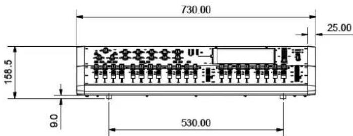
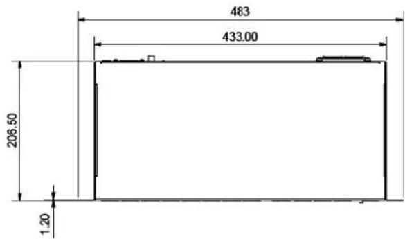
| Dimensions and Weights | |
| GLD-80 Mixer | Width x Depth x Height |
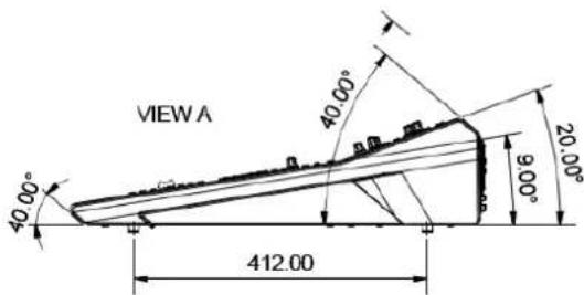
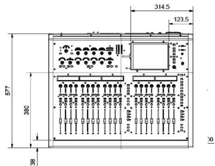
| Unpacked | 730 x 577 x 159mm (28.7" x 22.7" x 6.2") |
| Packed in shipping box | 930 x 730 x 290mm(36.6" x 28.6" x 11.4") |
| Unpacked weight | 16.5kg (36lbs) |
| Packed weight | 21.2kg ( 46.6lbs) |
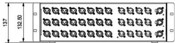
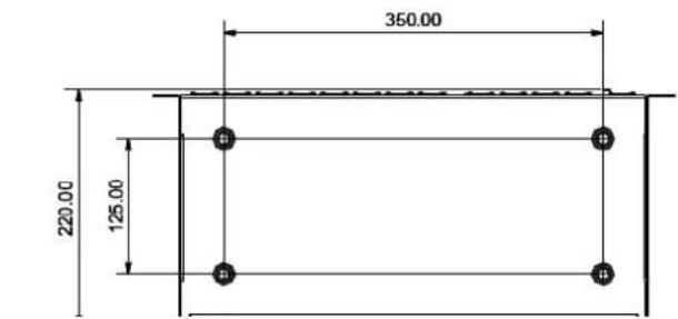
| GLD-AR2412 AudioRack | Width x Depth x Height |
| Unpacked | 483 x 220 x 137mm (19" x 8.6" x 5.4") 3U rack |
| Packed in shipping box | 600 x 350 x 250mm(23.6" x 13.7" x 9.8") |
| Unpacked weight | 5kg (11lbs) |
| Packed weight | 6.4kg (14lbs) |
| GLD-AR2412 AudioRack | Width x Depth x Height |
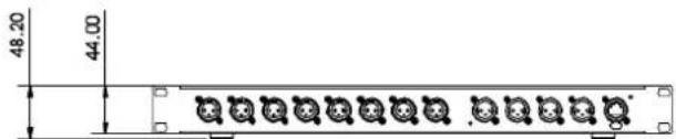
| Unpacked | 483 x 220 x 48mm (19" x 8.6" x 1.9") 1U rack |
| Packed in shipping box | 600 x 330 x 143mm(23.6" x 12.9" x 5.6") |
| Unpacked weight | 3kg (6.6lbs) |
| Packed weight | 4.4kg (9.7lbs) |
For the new user or guest engineer to start mixing with GLD. It assumes a mixer already configured for the show. To learn more about configuration, memories and advanced functions read the on-screen Help Manual and User Guide AP8561.


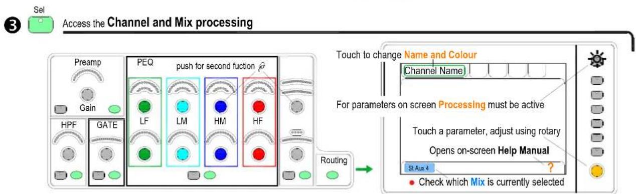
flowchart
graph TD
    A["Access the Channel and Mix processing"] --> B["PEQ"]
    B --> C["LF"]
    B --> D["LM"]
    B --> E["HM"]
    B --> F["HF"]
    B --> G["Routing"]
    H["Touch to change Name and Colour"] --> I["Channel Name"]
    J["For parameters on screen Processing must be active"] --> K["Touch a parameter, adjust using rotary"]
    K --> L["Opens on-screen Help Manual"]
    M["Check which Mix is currently selected"] --> N["St. Aux 4 ?"]
For GEQ on faders press GEQ Fader Flip - Master on last fader. RTA on strip meters. RTA follows current selected PAFL
4 Mix Access the Sends and Assignments
flowchart
graph TD
    subgraph_Normal_mix_mode["Normal mix mode (FOH)"]
        A1["IP 1 IP 2 IP 3 IP 4 IP 5 IP 6 P7 IP 8 Aux1 Aux2"] --> B1["Mix"]
        B1 --> C1["+ press Mix"]
        C1 --> D1["Assign Routing"]
        D1 --> E1["Hold down"]
        E1 --> F1["Channel faders Master faders"]
        F1 --> G1["Mix"]
        G1 --> H1["Crossing Block"]
        H1 --> I1["Hold down"]
        I1 --> J1["Aux3"]
        J1 --> K1["LR"]
        K1 --> L1["Crossing Block"]
        L1 --> M1["Mix"]
    end

    subgraph_DCA_and_Audio_Group["DCA and Audio Group assign"]
        N1["IP 4 IP 5 ON"] --> O1["+ press Mix"]
        O1 --> P1["Assign"]
        P1 --> Q1["Hold down"]
        Q1 --> R1["all"]
        R1 --> S1["Crossing Block"]
        S1 --> T1["Crossing Block"]
        T1 --> U1["Press Mix again to return to Main mix"]
    end

    subgraph_Master_Mix_views["Master Mix view"]
        V1["IP 1 IP 2 IP 3 IP 4 IP 5 IP 6 P7 IP 8 Aux1"] --> W1["+ press Sel Pre/Post"]
        W1 --> X1["+ press Mix Assign Routing"]
        X1 --> Y1["Hold down"]
        Y1 --> Z1["Aux2"]
        Z1 --> AA["Aux3"]
        AA --> AB["Aux4"]
        AB --> AC["Aux4"]
        AC --> AD["All sends to one master Master faders Channel faders"]
    end

    subgraph_Channel_MixViews["Channel Mix view"]
        AE["IP 4 IP 5"] --> AF["IP 5 IP 6 IP 7 IP 8 Aux1 Aux2"]
        AF --> AG["Pre/Post"]
        AG --> AH["Hold down"]
        AH --> AI["Select"]
        AI --> AJ["Assign Routing"]
        AJ --> AK["Aux3"]
        AK --> AL["Aux4"]
        AL --> AM["All sends from one input"]
    end
5 Access the FX
To send to an FX - press FX master Mix
To adjust FX parameters - press FX strip Sel
To return to the mix use related FXret channel
To Link parameters eg, 2 channels for stereo keyboard Use the Ganging screen. Choose attributes.
• Ganging does not link the Gains or Trims.
7 To Copy parameters
Hold down Copy and press the Sel or Mix key of the parameters to copy:
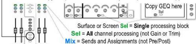
Now hold down Paste and press the Sel or Mix key of the strip to paste to


- GLD Digital Audio Mixing System
- User Guide
- Limited One Year Manufacturer's Warranty
- Conditions Of Warranty
- ALLEN&HEATH
- IMPORTANT - Read these instructions before starting:
- Safety instructions
- System operating firmware
- Software licence agreement
- Further information
- General precautions
- Safety Sheets
- Accessories available
- LEDlamp
- Table of Contents
- Important note about this guide
- Systems
- GLD Remote app for iPad
- Introduction
- GLD components
- Compatibility with iLive
- Key features
- System block diagram
- Input and output sockets
- Socket numbering
- GLD Remote iPad app and wireless router
- The router:
- Recommended settings:
- Recall a 'Template Show' as a starting point
- The Show Manager screen
- Template1 LR
- Template2 LRM (also use for LCR)
- Template3 Mon
- A few things to know before starting
- The Home Screen
- The strip LCD display
- The Fader Banks
- The Fader Strip keys
- Working with the Mix on the fader strips
- Working with Scenes
- USB Folders
- Firmware update instructions for Windows:
- Step1 Download the firmware
- Step2 Remove any previous GLD Firmware from your USB key
- Step3 Open and extract the Zip file to your USB key
- Step4 Safely remove the USB key from your computer
- Step5 Plug the key into a USB port on the GLD
- Step6 Perform the update
- Step7 Recall your settings
- Firmware update instructions for Mac:
- Step3 Extract the Zip file and copy the folder to your USB key
- Step4 Eject the USB key from your computer
- Access the FX
- To Link parameters eg, 2 channels for stereo keyboard Use the Ganging screen. Choose attributes.
- To Copy parameters
Brand : ALLEN & HEATH
Model : GLD Digital Audio Mixing System
Category : Mixing console