
Grand Cherokee SRT (2007) - Automobile JEEP - Free user manual and instructions
Find the device manual for free Grand Cherokee SRT (2007) JEEP in PDF.


| Product Type | Automobile |
| Brand | Jeep |
| Model | Grand Cherokee SRT8 |
| Model Year | 2007 |
| Engine Type | 6.1L HEMI V8 |
| Horsepower | 425 hp @ 6200 rpm |
| Transmission | 5-speed automatic with AutoStick |
| Drivetrain | Full-time all-wheel drive (AWD) |
| Fuel Type | Gasoline (premium recommended) |
| Fuel Tank Capacity | 21.1 gallons (80 liters) |
| Length | 186.6 in (4,740 mm) |
| Width | 72.9 in (1,852 mm) |
| Height | 66.5 in (1,689 mm) |
| Wheelbase | 109.5 in (2,781 mm) |
| Curb Weight | Approx. 4,600 lbs (2,087 kg) |
| Seating Capacity | 5 passengers |
| Safety Systems | Front and side curtain airbags, ABS, ESP, traction control, roll mitigation |
| Key Features | Remote keyless entry, remote start, UConnect hands-free, power windows, heated seats, sunroof |
| Maintenance | Regular oil changes, tire rotation, brake inspection per schedule |
| Cleaning | Hand wash recommended; avoid abrasive cleaners |
| Replacement Parts | Genuine Mopar parts recommended |
| Document Type | Owner's manual (PDF) |
| Manual Pages | 400 |
Frequently Asked Questions - Grand Cherokee SRT (2007) JEEP
User questions about Grand Cherokee SRT (2007) JEEP
0 question about this device. Answer the ones you know or ask your own.
Ask a new question about this device
Download the instructions for your Automobile in PDF format for free! Find your manual Grand Cherokee SRT (2007) - JEEP and take your electronic device back in hand. On this page are published all the documents necessary for the use of your device. Grand Cherokee SRT (2007) by JEEP.
USER MANUAL Grand Cherokee SRT (2007) JEEP
■Vehicle Identification Number 8
■Vehicle Modifications / Alterations ..... 9
4INTRODUCTION
INTRODUCTION
Thank you for selecting a Jeep®Grand Cherokee SRT8 and welcome to our worldwide family.
Before you start to drive this vehicle, read this manual. Be sure you are familiar with all vehicle controls, particularly those used for braking, steering and transmission shifting. Learn how your vehicle handles on different road surfaces. Your driving skills will improve with experience. Always observe federal, state, provincial, and local laws wherever you drive.
RollOverWarning
Utility vehicles have a significantly higher roll over rate than other types of vehicles. This vehicle has a higher ground clearance, higher center of gravity, and narrower track than many passenger cars. It is capable of performing better in a wide variety of off-road applications.
Driven in an unsafe manner, all vehicles can be caused to go out of control. Because of the higher center of gravity and the narrower track, if this vehicle is out of control it may roll over when some other vehicles may not.
Do not attempt sharp turns or abrupt maneuvers or other unsafe driving actions that can cause loss of vehicle control. Failure to operate this vehicle safely may result in an accident, roll over of the vehicle, and severe or fatal injury. Drive carefully.

80bfe0f0
RollOverWarningLabel
Failuretousedriverandpassengerseatbeltsprovided is a major cause of severe or fatal injury. In fact, the U.S. government notes that the universal use of existing seat belts could cut the highway death toll by 10,000 or more each year, and could reduce disabling injuries by 2
million annually. In a roll over crash an unbelted person is significantly more likely to die than a person wearing a seat belt. Always buckle up.
This manual has been prepared with the assistance of service and engineering specialists to acquaint you with the operation and maintenance of your new vehicle. It is supplemented by a Warranty Information Booklet and various customer oriented documents. You are urged to read these publications carefully. Following the instructions and recommendations in this manual will help assure safe and enjoyable operation of your vehicle.
NOTE: After you read the manual, it should be stored in the vehicle for convenient reference and remain with the vehicle when sold so that thenew owner will be aware of falls safety warnings.
6INTRODUCTION
When it comes to service, remember that your authorized dealer knows your vehicle best, has the factory-trained technicians and genuine Mopar® parts, and is interested in your satisfaction.
WARNING!
Engineexhaust, some of its constituents, and certain vehicle components contain an remit chemicals known to the State of Californiatocause cancer and birth defects or other reproductive harm. In addition, certain fluids contained in vehicles and certain products of component wear contain an remit chemicals known to the State of Californiatocause cancer and birth defects or other reproductive harm.
HOWTOUSETHISMANUAL
Consult the table of contents to determine which section contains the information you desire.
The detailed index, at the rear of this manual, contains a complete listing of all subjects.
Consult the following table for a description of the symbols that may be used on your vehicle or throughout this owner's manual:
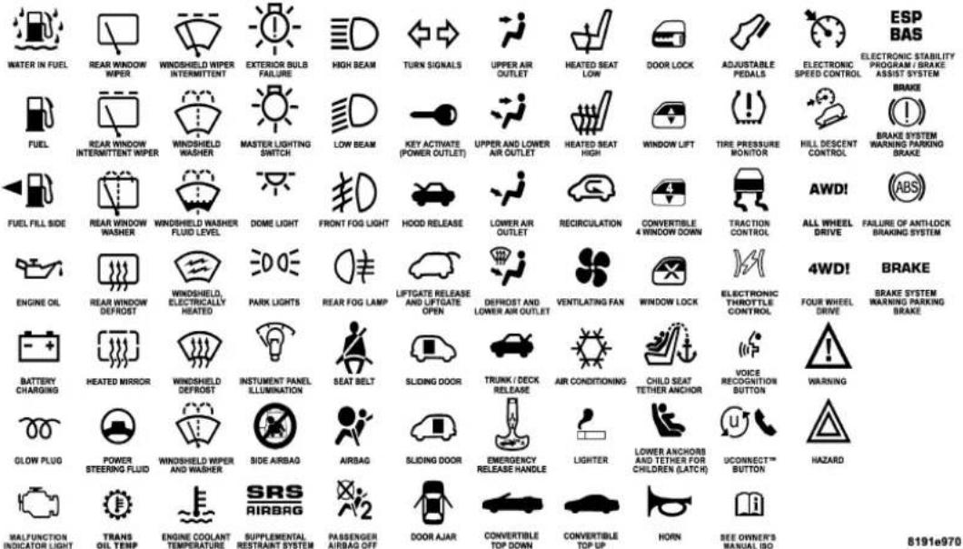
8INTRODUCTION
WARNINGSANDCAUTIONS
This manual contains WARNINGS against operating procedures which could result in an accident or bodily injury. It also contains CAUTIONS against procedures which could result in damage to your vehicle. If you do not read this entire manual you may miss important information. Observe all Warnings and Cautions.
VEHICLEIDENTIFICATIONNUMBER
The vehicle identification number (VIN) is found on a label located on the left front corner of the instrument panel pad, visible from outside of the vehicle through the windshield. This number also appears on the Automobile Information Disclosure Label affixed to a window on your vehicle. Save this label for a convenient record of your vehicle identification number and optional equipment.

NOTE: It is illegal to remove the VIN label.
VEHICLEMODIFICATIONS/ALTERATIONS
WARNING!
Anymodificationsoralterationstothisvehicle couldseriouslyaffectitsroadworthinessandsafety andmayleadtoanaccidentresultinginserious injuryordeath.
THINGSTOKNOWBEFORESTARTINGYOURVEHICLE
CONTENTS
■A Word About Your Keys....14
□Ignition Key Removal....14
□Key-In-Ignition Reminder....15
■Sentry Key Immobilizer System....1 5
□Important Note About Service....16
□Replacement Keys....17
□Customer Key Programming....17
□General Information....18
■ Security Alarm System — If Equipped .....18
□To Set The Alarm....18
□ To Disarm The System .....19
■Illuminated Entry 19
■ Remote Keyless Entry .....19
□To Unlock The Doors 20
□To Lock The Doors....2 1
□ To Release The Liftgate Flipper Glass .....21
□Using The Panic Alarm....2 2
□General Information....23
12 THINGSTOKNOWBEFORESTARTINGYOURVEHICLE
□Transmitter Battery Service....23
■Remote Starting System — If Equipped . . . . . . . 2 4
■Door Locks....26
□Manual Door Locks....26
□Power Door Locks — If Equipped . . . . . . . . . 2 6
□Child Protection Door Lock....28
■Windows....29
□Power Windows....29
□Wind Buffeting....3 2
■Liftgate....32
□Liftgate Flipper Glass....3 3
■Occupant Restraints....3 4
□Lap/Shoulder Belts....35
□Lap/Shoulder Belt Operating Instructions ..... 3 6
□Adjustable Upper Shoulder Belt Anchorage . . . . 4 0
□Automatic Locking Mode — If Equipped . . . . 4 0
□Energy Management Feature....4 1
□Seat Belt Pretensioners....4 1
□Seat Belts And Pregnant Women . . . . . . . . . . . 4 2
□Seat Belt Extender....42
□Driver And Front Passenger Supplemental Restraint Systems (SRS)....43
□Child Restraint 54
■ Engine Break-In Recommendations .....64
■Safety Tips....6 5
□Exhaust Gas....65
□Safety Checks You Should Make Inside The Vehicle....6 6
THINGSTOKNOWBEFORESTARTINGYOURVEHICLE13
□Safety Checks You Should Make Outside The Vehicle....67
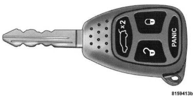
The keys for your new vehicle are enclosed in a plastic bag with the key code number on it. If you received your keys without the bag, ask your authorized dealer to give you the number. The key code can also be obtained by your authorized dealer from your vehicle invoice.
natural_image
Illustration of a car key with four key buttons and a 2x2 display (no text or symbols on the main body)IgnitionKey
IgnitionKeyRemoval
Place the shift lever in P (Park). Turn the ignition switch to the OFF position, and remove the key.

IgnitionKeyPositions
An unlocked carisan invitation to thieves. Always remove key from the ignition and lockalldoors when leaving the vehicle unattended.
Key-In-IgnitionReminder
If the driver's door is opened when the key is in the ignition and not turned to the ON position, a chime will sound to remind you to remove the key.
SENTRYKEYIMMOBILIZERSYSTEM
The Sentry Key Immobilizer System (SKIM) prevents unauthorized operation of the vehicle by disabling the engine. The system will shut the engine down after 2 seconds of running if an invalid key is used to start the vehicle. This system utilizes ignition keys which have an electronic chip (transponder) embedded into them. Only keys that have been programmed to the vehicle can be used to start and operate the vehicle for longer than the 2 second validation time period.
The Sentry Key Immobilizer System does not need to be armed or activated. Operation of the system is automatic regardless of whether or not the vehicle is locked or unlocked. During normal operation, the SKIM indicator
light will come on for 3 seconds immediately after the ignition switch is turned on for a bulb check. Afterwards, if the bulb remains on, this indicates a malfunction in the electronics. If the bulb begins to flash immediately after the ignition switch is turned on, this indicates that an invalid key is being used to start the vehicle. Both of these conditions will result in the engine being shut down after 2 seconds of running. Keep in mind that a key which has not been programmed is also considered an invalid key even if it is cut to fit the ignition for that vehicle.
If the SKIM indicator light comes on during normal vehicle operation (it has been running for longer than 10 seconds) a fault has been detected in the electronics and the vehicle should be serviced as soon as possible.
NOTE:
- The Sentry Key Immobilizer System is not compatible
with remote starting systems. Use of these systems may result in vehicle starting problems and loss of security protection.
- Mobil Speedpass™, additional Sentry Keys, or any other transponder equipped components on the same keychain will not cause a key-related (Transponder) fault unless the additional part is physicallyheld against the ignition key being used when starting the vehicle. Also, cell phones, pagers, or other RF electronics will not cause interference with this system.
All of the keys provided with your new vehicle have been programmed to the vehicle electronics.
ImportantNoteAboutService
A four digit PIN number is needed to service the Sentry Key Immobilizer System. This number can be obtained from your authorized dealer. However, this number can also be found on your customer invoice that you were given upon receipt of your vehicle.
ReplacementKeys
NOTE: Only keys that have been programmed to the vehicle electronics can be used to start the vehicle. Once a Sentry Key has been programmed to a vehicle, it cannot be programmed to any other vehicle.
At the time of purchase, the original owner is provided with a four digit PIN number. This number is required for dealer replacement of keys. Duplication of keys may be performed at an authorized dealer or by using the Customer Key Programming procedure. This procedure consists of programming a blank key to the vehicle electronics. A blank key is one which has never been programmed.
NOTE: When having the Sentry Key System serviced, bring all vehicle keys to the dealer.
CustomerKeyProgramming
You can program new keys to the system if you have two valid keys by doing the following:
- Cut the additional Sentry Key Transponder blank(s) to match the ignition switch lock cylinder key code.
- Insert the first valid key into the ignition switch and turn the ignition switch ON for at least 3 seconds but no longer than 15 seconds. Turn the ignition switch OFF and remove the first key.
- Insert the second valid key and turn the ignition switch ON within 15 seconds. After ten seconds, a chime will sound and the SKIM indicator light will begin to flash. Turn the ignition switch OFF and remove the second key.
- Insert a blank Sentry Key into the ignition switch and turn the ignition switch ON within 60 seconds. After 10 seconds, a single chime will sound. The SKIM indicator light will stop flashing, turn on for 3 seconds; then turn off.
The new Sentry Key has been programmed. Repeat this process to program up to a total of 8 keys.
GeneralInformation
The Sentry Key Immobilizer System complies with FCC rules part 15 and with RSS-210 of Industry Canada. Operation is subject to the following two conditions:
-
This device may not cause harmful interference.
-
This device must accept any interference that may be received, including interference that may cause undesired operation.
SECURITYALARMSYSTEM—IFEQUIPPED
This system monitors the vehicle doors, liftgate, liftgate flipper glass, and ignition for unauthorized operation and movement inside of the vehicle. When the alarm is activated, the system provides both audible and visual signals. The horn will sound repeatedly for three minutes and the headlights and taillights will flash for an additional 15 minutes.
ToSettheAlarm
The alarm will set when you use the remote keyless entry transmitter to lock the doors and liftgate or when you use the power door lock switch while the door is open. After all the doors are locked and closed, a red light (located in the instrument cluster) will flash rapidly for about 16 seconds to signal that the system is arming. During this 16 second pre-arm period, opening any door or the liftgate will cancel the arming. If the system successfully arms, the red light will flash at a slower rate to indicate the alarm is set. A manual lock of the doors, either with
THINGSTOKNOWBEFORESTARTINGYOURVEHICLE19
the door lock plunger located on the inside of the doors or with the driver's door key lock cylinder, will not set the alarm.
ToDisarmtheSystem
To disarm the system, use the remote keyless entry transmitter. Also, using a valid sentry key and moving the ignition switch to the ON/START position will disarm the system. If something has triggered the system in your absence, the horn will sound three times when you unlock the doors. Check the vehicle for tampering.
The Security Alarm System is designed to protect your vehicle; however, you can create conditions where the system will arm unexpectedly. If you remain in the vehicle and lock the doors with the transmitter, once the system is armed (after 16 seconds), when you move inside of the vehicle or you pull the door handle to exit the alarm will sound. If this occurs, press the "Unlock" button on the remote keyless entry transmitter to disarm the system. The Security Alarm System will not disarm with a manual unlock, either through the lock plunger located on the inside of the door, or through a key in the driver's door key cylinder.
ILLUMINATEDENTRY
The interior lights come on when you open any door. They will remain on for about 30 seconds after all doors are closed then fade to off.
The lights also will fade to off if you turn on the ignition after you close all the doors.
REMOTEKEYLESSENTRY
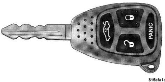
This system allows you to lock or unlock the doors, liftgate, or activate the panic alarm from distances up to about 23 feet (7 meters) using a hand held transmitter. The transmitter does not need to be pointed at the vehicle to activate the system.
20THINGSTOKNOWBEFORESTARTINGYOURVEHICLE
NOTE: If the key is in the ignition switch, then all buttons on that transmitter will be disabled. The buttons on the remaining transmitters will work. If the vehicle is shifted out of P (Park), all the transmitter buttons are disabled for all keys.
natural_image
Illustration of a car key with four key icons and 'PANIC' label (no text or symbols on the key itself)FourButtonTransmitter

natural_image
Illustration of a car key with labeled buttons and a 'PANIC' button (no text or symbols beyond basic labels)FiveButtonTransmitter
ToUnlocktheDoors
Press and release the "Unlock" button on the transmitter once to unlock the driver's door, or twice to unlock all doors. The turn signal lights will flash twice to acknowledge the unlock signal. The illuminated entry system also turns on.
THINGSTOKNOWBEFORESTARTINGYOURVEHICLE21
NOTE: If desired, the system can be programmed to unlock all doors on the first press of the "Unlock" button. Refer to "Remote Unlock Driver's Door 1st" in the Personal Settings section of the "Electronic Vehicle Information Center (EVIC)", or simply follow these steps:
-
Press and hold the "Lock" button for 4 to 10 seconds.
-
While the "Lock" button is pressed, (after 4 seconds) press the "Unlock" button. Release both buttons.
The "Remote Unlock Driver's Door 1st" feature can be reactivated by repeating this procedure.
ToLocktheDoors
Press and release the "Lock" button on the transmitter to lock all doors. The turn signal lights will flash once to acknowledge the lock signal. The horn will chirp once to acknowledge the signal. If desired, the "Sound Horn On Lock" feature can be turned on and off by referring to the Customer Programmable Features of the “Electronic Vehicle Information Center (EVIC)” section or by following these steps.
- Press and hold the "Lock" button for 4 to 10 seconds.
- While the "Lock" button is pressed (after 4 seconds), press the PANIC button. Release both buttons.
The "Sound Horn On Lock" feature can be reactivated by repeating this procedure.
ToReleasetheLiftgateFlipperGlass
Press the "Flipper Glass/Trunk Release" button on the transmitter two times to release the flipper glass.
Drivingwiththeflipperglassopencanallowpoisonousehaustgasesintoyourvehicle.Youandyour passengerscouldbeinjuredbythesefumes.Keep theflipperglassclosedwhenyouareoperatingthe vehicle.
UsingThePanicAlarm
To turn the panic alarm feature ON or OFF, press and hold the PANIC button on the transmitter for at least one second and release. When the panic alarm is on, the headlights and park lights will flash, the horn will pulse on and off and the interior lights will turn on.
The panic alarm will stay on for 3 minutes unless you turn it off by pressing the PANIC button a second time or if the vehicle speed is 15 mph (24 km/h) or greater.
NOTE: The interior lights will turn off when the ignition is switched to the ACC or ON position after the panic alarm is activated. However, the exterior lights and horn will remain on.
NOTE: When you turn off the panic alarm by pressing the PANIC button a second time, you may have to be closer to the vehicle due to the radio frequency noises of the system.
ToTurnOff"FlashLightsOnLock/Unlock"
NOTE: If desired, the "Flash Lights On Lock/Unlock" feature can be turned on and off by referring to the Customer Programmable Features of the "Electronic Vehicle Information Center (EVIC)" section or by following these steps.
- Press and hold the "Unlock" button for 4 to 10 seconds.
THINGSTOKNOWBEFORESTARTINGYOURVEHICLE23
- While the "Unlock" button is pressed, (after 4 seconds) press the "Lock" button. Release both buttons.
The "Flash Lights On Lock/Unlock" feature can be reactivated by repeating this procedure.
GeneralInformation
This device complies with part 15 of the FCC rules and RSS 210 of Industry Canada. Operation is subject to the following conditions:
- This device may not cause harmful interference.
- This device must accept any interference received, including interference that may cause undesired operation.
If your Remote Keyless Entry transmitter fails to operate from a normal distance, check for these two conditions.
- A weak battery in the transmitter. The expected life of the battery is a minimum of three years.
- Closeness to a radio transmitter such as a radio station tower, airport transmitter, and some mobile or CB radios.
TransmitterBatteryService
The recommended replacement battery is one CR2032 battery.
NOTE: Do not touch the battery terminals that are on the back housing or the printed circuit board.
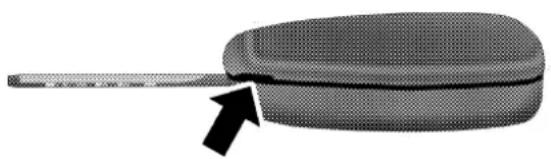
- With the transmitter buttons facing down, remove the small screw, and separate the two halves of the transmitter. Make sure not to damage the rubber gasket during removal.
natural_image
Close-up of a textured, oval-shaped object with a black arrow pointing to it, no visible text or symbols.81182c72
SeparatingTransmitterHalves
- Remove and replace the battery. Avoid touching the new battery with your fingers. Skin oils may cause battery deterioration. If you touch a battery, clean it with rubbing alcohol.
- To reassemble the transmitter case, join the two halves of the case together. Install and tighten the screw until snug. Make sure there is an even "gap" between the two halves. Test transmitter operation.
REMOTESTARTINGSYSTEM—IFEQUIPPED
Your vehicle may be equipped with a remote starting system, which will allow the vehicle to be started up to 300 feet (91 meters) away from the vehicle using the remote keyless entry key fob which is part of your ignition key.
In order to remote start your vehicle, the hood, liftgate, and all of the doors must be closed.
THINGSTOKNOWBEFORESTARTINGYOURVEHICLE25
To remote start your vehicle, press the "Lock" button on the key fob once, then within three seconds press the "Remote Start" button twice. To indicate that the vehicle is about to start, the parking lights will flash and the horn will sound briefly.

RemoteStartButton
Once the vehicle has started, the engine will run for 15 minutes. To cancel remote start, press the "Remote Start" button twice within two seconds.
To enter the vehicle while the engine is running during a remote start, you must first unlock the vehicle using the "Unlock" button on the key fob. After the vehicle is unlocked, you have 60 seconds to enter the vehicle, insert the key into the ignition, and move it to the RUN position. Otherwise, the engine will cancel remote start and automatically turn off.
Remote start will also cancel if any of the following occur:
• If the engine stalls or RPM exceeds 2500
• Any engine warning lamps come on
• The hood is opened
• The hazard switch is pressed
• The transmission is moved out of P (Park).
The vehicle can be started remotely up to a maximum of two times. The vehicle is also allowed a maximum of one failed start, where the remote start sequence was initiated but cancelled before the engine begins to crank. After either of these conditions, or if the Vehicle Theft Alarm is alarming, or if the PANIC button was pressed, the vehicle must be reset by inserting a valid key into the ignition and moving it to the RUN position, then back to LOCK.
DOORLOCKS
ManualDoorLocks
Use the manual door lock plunger to lock the doors from inside the vehicle. If the plunger is down when the door is closed, the door will lock. Therefore, make sure the keys are not inside the vehicle before closing the door.
WARNING!
- Forpersonalsecurityandsafetyintheeventofan accident,lockthevehicledoorswhenyoudriveas wellaswhenyouparkandleavethevehicle.
- Whenleavingthevehiclealwaysremovethekey fromtheignitionlock,andlockyourvehicle.Do notleavechildrenunattendedinthevehicle,or withaccesstoun unlocked vehicle.Unsupervised useofvehicleequipmentmaycauseseverepersonalinjuriesanddeath.
PowerDoorLocks—IfEquipped
A door lock switch is on each front door panel. Press this switch to lock or unlock the doors.
THINGSTOKNOWBEFORESTARTINGYOURVEHICLE27

natural_image
Close-up of a car's front panel with a circular dial and control buttons, showing no visible text or symbols.PowerDoorLockSwitch
If the plunger is down when the door is closed, the door will lock. Therefore, make sure the keys are not inside the vehicle before closing the door.
If you press the door lock switch while the keys are in the ignition switch, and the driver's door is open, the doors will not lock.
The rear doors cannot be opened from inside the vehicle until you pull up the lock plungers.
AutomaticDoorLocks
If this feature is selected your door locks will lock automatically if the vehicle speed is above 15 mph (24 km/h) and all doors are closed. It will reset whenever a door is opened.
This feature is selectable and can be turned on or off. Refer to "Electronic Vehicle Information Center (EVIC) — Customer Programmable Features" in Section 4 of this manual or see your authorized dealer.
AutomaticUnlockonExitFeature—Only Available if AutoLockisEnabled
This feature will unlock all the doors when the driver's door is opened if the vehicle is stopped and in P (Park) or N (Neutral). Refer to "Electronic Vehicle Information Center (EVIC) — Customer Programmable Features" in Section 4 of this manual or see your authorized dealer.
The rear doors of your vehicle are equipped with child protection locks. If you push up on the lever on the open edge of the door it cannot be opened from the inside of the vehicle. Push the lever down to disengage the child protection locks.
WARNING!
Avoidtrappinganyoneinthevehicleinacollision. Rememberthatthereardoorscanonlybeopened fromtheoutsidewhenthechildprotectionlocksare engaged.

natural_image
Close-up of a garment collar with a zipper and arrow indicator (no readable text or symbols)ChildProtectionDoorLock
THINGSTOKNOWBEFORESTARTINGYOURVEHICLE29
WINDOWS
PowerWindows
The power window controls are located on the driver's door trim panel. There is a single switch on the front passenger door/rear doors which operates the front passenger/rear passenger door windows. The window controls will operate only when the ignition switch is in the ON or ACCESSORY position.

natural_image
Interior view of a car dashboard with control panel and door (no visible text or symbols)PowerWindowSwitches
The power window switches remain active for up to 10 minutes after the ignition switch has been turned off. Opening a vehicle front door will cancel this feature.
Both the driver and front passenger window switch has an "Auto Down" feature. Press the window switch past the first detent, release, and the window will go down automatically. To cancel the "Auto Down" movement, operate the switch in either the up or down direction and release the switch.
To stop the window from going all the way down during the auto-down operation, pull up on the switch briefly.
To open the window part way, press to the first detent and release it when you want the window to stop.
The power window switches remain active for 10 minutes after the ignition has been turned off. Opening either front door will cancel this feature.
AutoUpFeaturewithAnti-PinchProtection (Driver'sandFrontPassengerDoorOnly)
Lift the window switch to the second detent, release, and the window will go up automatically.
To stop the window from going all the way up during the auto-up operation, push down on the switch briefly.
To close the window part way, lift the window switch to the first detent and release when you want the window to stop.
NOTE: If the window runs into any obstacle during the auto-closure it will reverse direction and then stop. Remove the obstacle and use the window switch again to close the window. Any impact due to rough road conditions may trigger the auto reverse function unexpectedly during auto closure. If this happens pull the switch lightly to the first detent and hold to close the window manually.
THINGSTOKNOWBEFORESTARTINGYOURVEHICLE31
WARNING!
Thereisnoanti-pinchprotectionwhenthewindow isalmostclosed.Besuretoclearalobjectsfromthe windowbeforeclosing.
ResettingtheAuto-UpFeature
Should the Auto-Up feature stop working the window probably needs to be reset. To reset Auto-Up:
Pull the window switch up and close the window completely, then pull and hold the switch for 1 second.
WindowLockoutSwitch
The window lockout switch on the driver's door allows you to disable the window control on the other doors. To disable the window controls on the other doors, press the window lockout button. To enable the window controls, press the window lockout button again.

natural_image
Interior view of a car air conditioner unit with two switches and a directional arrow (no text or symbols)PowerWindowLock
Wind buffeting can be described as the perception of pressure on the ears or a helicopter type sound in the ears. Your vehicle may exhibit wind buffeting with the windows down, or the sunroof (if equipped) in certain open or partially open positions. This is a normal occurrence and can be minimized. If the buffeting occurs with the sunroof open, adjust the sunroof opening to minimize the buffeting.
LIFTGATE
To open the liftgate, pull up (squeeze) on the handle and lift. Manually unlocking the vehicle doors with the plunger or a key in the lock cylinder will not unlock the liftgate.

natural_image
Front view of a car showing the rear bumper and side panel (no text or symbols)8167d4ce
LiftgateRelease
THINGSTOKNOWBEFORESTARTINGYOURVEHICLE33
WARNING!
Drivingwiththeliftgateopencanallowpoisonous exhaustgasesintoyourvehicle.Youandyourpassengerscouldbeinjuredbythesefumes.Keepthe liftgateclosedwhenyouareoperatingthevehicle.
LiftgateFlipperGlass
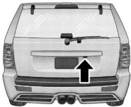
The liftgate flipper glass is also unlocked when the liftgate is unlocked. To open the flipper glass, push up on the window switch located on the liftgate.
natural_image
Front view of a white car with a mounted gun and a black upward arrow pointing to the side grille (no text or symbols)8167d4e0
LiftgateGlassRelease
WARNING!
To avoid injurystandback when opening. Glass will automatically rise.
Once the liftgate flipper glass has been opened, connection to the rear window wiper is interrupted, preventing activation of the rear wiper blade while the flipper glass is open.
NOTE: If a power malfunction to the power liftgate latch should occur, an emergency liftgate latch release can be used to open the liftgate. The emergency liftgate latch release can be accessed through a snap-in cover located on the liftgate trim panel.
WARNING!
Drivingwiththeflipperglassopencanallowpoisonousexhaustgasesintoyourvehicle.Youandyour passengerscouldbeinjuredbythesefumes.Keep theflipperglassclosedwhenyouareoperatingthe vehicle.
OCCUPANTRESTRAINTS
Some of the most important safety features in your vehicle are the restraint systems. These include the front and rear seat belts for the driver and all passengers, front airbags for both the driver and right front passenger, and window bags for the driver and passengers seated next to a window. If you will be carrying children too small for adult-size belts, your seat belts also can be used to hold infant and child restraint systems.
NOTE: The front airbags have a multi stage inflator design. This allows the airbag to have different rates of inflation that are based on collision severity.
Please pay close attention to the information in this section. It tells you how to use your restraint system properly to keep you and your passengers as safe as possible.
THINGSTOKNOWBEFORESTARTINGYOURVEHICLE35
WARNING!
Inacollision, you and your passengers can suffer injuries, including fatalities, if you are not properly buckled up. You can strik the interior of your vehicle or other passengers, or you can be thrown out of the vehicle. Always besure you and others in your vehicle are buckled up properly.
Buckle up even though you are an excellent driver, even on short trips. Someone on the road may be a poor driver and cause a collision which includes you. This can happen far away from home or on your own street.
Research has shown that seat belts save lives, and they can reduce the seriousness of injuries in a collision. Some of the worst injuries happen when people are thrown from the vehicle. Seat belts reduce the possibility of ejection and the risk of injury caused by striking the inside of the vehicle. Everyone in a motor vehicle should be belted at all times to reduce or prevent injuries.
Lap/ShoulderBelts
All seating positions in your vehicle have combination lap/shoulder belts. The belt webbing retractor is designed to lock during very sudden stops or collisions. This feature allows the shoulder part of the belt to move freely with you under normal conditions. But in a collision, the belt will lock and reduce the risk of you striking the inside of the vehicle or being thrown out.
WARNING!
- Wearingseatbeltincorrectlyisdangerous.Seat beltsaredesignedtogoaroundthelargebonesof yourbody.Thesearethestrongestpartsofyour bodyandcantaketheforcesofacollisionthe best.Wearingyourbeltinthewrongplacecould makeyourinjuriesinacollisionmuchworse.You mightsufferinternalinjuries,oryoucouldeven slideoutofpartofthebelt.Followtheseinstructionstowearyourseatbeltsafelyandtokeep yourpassengerssafe,too.
- Twopeopleshouldneverbebeltedintoasingle seatbelt.Peoplebeltedtogethercancrashintoone anotherinanaccident,hurtingoneanotherbadly. Neverusealap/shoulderbeltoralapbeltfor morethanoneperson,nomatterwhattheirsize.
Lap/ShoulderBeltOperatingInstructions
- Enter the vehicle and close the door. Sit back and adjust the seat.
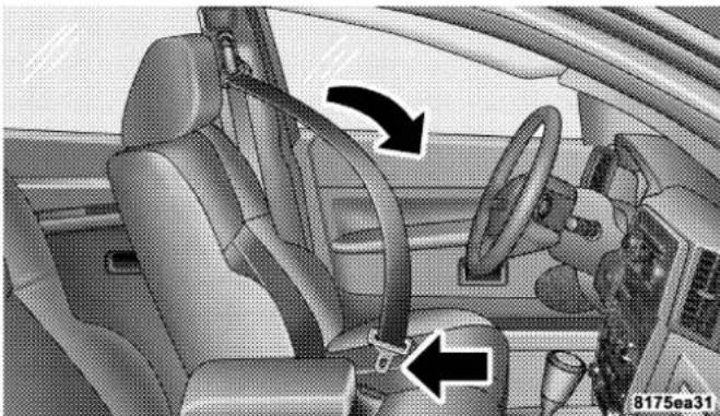
- The seat belt latch plate is above the back of your seat. Grasp the latch plate and pull out the belt. Slide the latch plate up the webbing as far as necessary to make the belt go around your lap.
THINGSTOKNOWBEFORESTARTINGYOURVEHICLE37
natural_image
Interior view of a car showing steering wheel, dashboard, and seatbelt (no text or symbols visible)LatchPlateLatchPlateToBuckle

natural_image
Interior view of a car showing steering wheel, dashboard, and driver's seat (no visible text or symbols)- When the belt is long enough to fit, insert the latch plate into the buckle until you hear a "click."
WARNING!
Abeltthatisbuckledintothewrongbucklewillnot protectyouproperly. Thelapportioncouldridetoo highonyourbody, possiblycausinginternalinjuries. Alwaysbuckleyourbeltintothebucklenearestyou.
Abeltthatistooloosewillnotprotectyouaswell.In asuddenstopyoucouldmovetoofarforward, increasingthepossibilityofinjury.Wearyourseat beltsnugly.
Abeltthatiswornunderyourarmisverydangerous. Yourbodycouldstriketheinsidesurfacesofthe vehicleinacollision,increasingheadandneckinjury. Abeltwornunderthearmcancauseinternalinjuries. Ribsaren'tasstrongassshoulderbones.Wearthebelt overyourshouldersothatyourstrongestboneswill taketheforceinacollision.
Ashoulderbeltplacedbehindwillnotprotectyou frominjuryduringacollision.Youaremorelikelyto hityourheadinacollisionifyoudonotwearyour shoulderbelt.Thelapandshoulderbeltaremeantto beusedtogether.
- Position the lap belt across your thighs, below your abdomen. To remove slack in the lap portion, pull up a bit on the shoulder belt. To loosen the lap belt if it is too tight, tilt the latch plate and pull on the lap belt. A snug belt reduces the risk of sliding under the belt in a collision.
WARNING!
Alapbeltworntoohighcanincreasetheriskof injuryinacollision.Thebeltforceswon'tbeatthe stronghipandpelvicbones,butacrossyourabdomen.Alwayswearthelappartofyourseatbeltas lowaspossibleandkeepitsnug.
Atwistedbeltcan'tdoitsjobaswell.Inacollision itcouldevencutintoyou.Besurethebeltisstraight. Ifyoucan'tstraightenabeltinyourvehicle,takeit toyourauthorizeddealerandhaveitfixed.
THINGSTOKNOWBEFORESTARTINGYOURVEHICLE39
- Position the shoulder belt on your chest so that it is comfortable and not resting on your neck. The retractor will withdraw any slack in the belt.

natural_image
Interior view of a car showing steering wheel, dashboard, and seatbelt (no text or symbols visible)RemovingSlackFromBelt
- To release the belt, push the red button marked PRESS on the buckle. The belt will automatically retract to its stowed position. If necessary, slide the latch plate down the webbing to allow it to retract fully.
WARNING!
Afrayedortornbeltcouldripapartinacollision andleaveyouwithnoprotection.Inspectthebelt systemperiodically,checkingforcuts,frays,orloose parts.Damagedpartsmustbereplacedimmediately. Donotdisassembleormodifythesystem.Seatbelt assembliesmustbereplacedafteranaccidentifthey havebeendamaged(bentretractor,tornwebbing, etc.).
AdjustableUpperShoulderBeltAnchorage
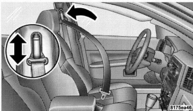
In the front seating positions, the shoulder belt can be adjusted upward or downward to position the belt away from your neck. Press the release button to release the anchorage, and then move it up or down to the position that serves you best.
natural_image
Interior view of a car showing a seatbelt buckle and steering wheel (no text or symbols visible)AdjustingUpperShoulderBelt
As a guide, if you are shorter than average, you will prefer a lower position, and if you are taller than average, you'll prefer a higher position. When you release the anchorage, try to move it up or down to make sure that it is locked in position.
AutomaticLockingMode—IfEquipped
In this mode, the shoulder belt is automatically pre-locked. The belt will still retract to remove any slack in the shoulder belt.
WhenToUseTheAutomaticLockingMode
Anytime a child safety seat is installed in the rear center seating position. Children 12 years old and under should be properly restrained in the rear seat whenever possible.
HowToUseTheAutomaticLockingMode
- Buckle the combination lap and shoulder belt.
-
Grasp the shoulder portion and pull downward until the entire belt is extracted.
-
Allow the belt to retract. As the belt retracts, you will hear a clicking sound. This indicates the safety belt is now in the automatic locking mode.
HowtoDisengageTheAutomaticLockingMode
Disconnect the combination lap/shoulder belt and allow it to retract completely to disengage the automatic locking mode and activate the vehicle sensitive (emergency) locking mode.
EnergyManagementFeature
This vehicle has a safety belt system with an energy management feature in the front seating positions to help further reduce the risk of injury in the event of a head-on collision.
This safety belt system has a retractor assembly that is designed to release webbing in a controlled manner. This feature is designed to help reduce the belt force acting on the occupant's chest.
WARNING!
- Thebeltandretractorassemblymustbereplaced iftheseatbeltassembly"automaticclockingretractor"featureoranyotherseatbeltfunctionisnotworkingproperlywhencheckedaccordingto theproceduresintheServiceManual.
- Failuretoreplacethebeltandretractorassembly couldincreaseetheriskofinjuryincollisions.
SeatBeltPretensioners
The driver and front passenger seat belts are equipped with a pretensioning device that is designed to remove any slack from the seat belt systems in the event of a collision. This device improves the performance of the seat belt by assuring that the belt is tight around the occupant early in a collision. Pretensioners work for all size occupants, including those in child restraints.
42 THINGSTOKNOWBEFORESTARTINGYOURVEHICLE
NOTE: These devices are not a substitute for proper seat belt placement by the occupant. The seat belt must still be worn snugly and positioned properly.
The pretensioners are triggered by the Occupant Restraint Control (ORC) Module. Like the front airbags, the pretensioners are a single use item. After a collision that is severe enough to deploy the airbags and pretensioners, they must be replaced.
SeatBeltsandPregnantWomen
We recommend that pregnant women use the seat belts throughout their pregnancy. Keeping the mother safe is the best way to keep the baby safe.
Pregnant women should wear the lap part of the belt across the thighs and as snug across the hips as possible. Keep the belt low so that it does not come across the abdomen. That way the strong bones of the hips will take the force if there is a collision.
SeatBeltExtender
If a seat belt is too short, even when fully extended and when the adjustable upper shoulder belt anchorage (if equipped) is in its lowest position, your authorized dealer can provide you with a seat belt extender. This extender should be used only if the existing belt is not long enough. When it is not required, remove the extender and store it.
WARNING!
Usingaseatbeltextenderwhennotneededcan increasetheriskofinjuryinacollision.Onlyuse whenthelapbeltisnotlongenoughwhenitisworn low and snug, and in the recommended seating positions.Removeandstoretheextenderwhennot needed.
DriverAndFrontPassengerSupplemental RestraintSystems(SRS)

THINGSTOKNOWBEFORESTARTINGYOURVEHICLE43
This vehicle has airbags for both the driver and right front passenger as a supplement to the seat belt restraint systems. The driver's front airbag is mounted in the steering wheel. The passenger side airbag is mounted in the instrument panel, above the glove compartment. The words SRS/AIRBAG are embossed on the airbag covers.
NOTE: The front airbags are certified to the Federal regulations that allow less forceful deployment.
The front airbags have a multistage inflator design. This may allow the airbag to have different rates of inflation that are based on collision severity and occupant size.
This vehicle is equipped with window bags to protect the driver, front, and rear passengers sitting next to a window. They are located above the side windows. Their covers are also labeled SRS/AIRBAG.
WindowAirbagLocation
NOTE: Airbag covers may not be obvious in the interior trim; but they will open to allow airbag deployment.
WARNING!
- Donotputanythingonoraroundthefrontairbag coversorattempttomanuallyopenthem.Youmay damagetheairbagsandyoucouldbeinjured becausetheairbagsarenolongerfunctional.These protectivecoversfortheairbagcushionsaredesignedtoopenonlywhentheairbagsareinflating.
- Donotstackluggageorothercargoughenoughtoblockthelocationofthewindowbag. Theareawherethewindowbagislocatedshould remainfreefromanyobstructions.
- Donothaveanyaccessoryitemsinstalledwhich willaltertheroof,includingaddingasunroofto yourvehicle.Donotaddroofracksthatrequire permanentattachments(boltsorscrews)forinstallationonthevehicleroof.Donotdrillintotheroof ofthevehicleforanyreason.
- Donotcoverorplaceitemsontheairbagcovers. Theseitemsmaycauseseriousinjuryduringinflation.
NOTE: Do not use a clothing bar mounted to the coat hooks in this vehicle. A clothing bar will impede the proper performance of the window bags.
The front airbags have a multi stage inflator design. This allows the airbag to have different rates of inflation that are based on collision severity. Along with the seat belts, front airbags work with the instrument panel knee bolsters to provide improved protection for the driver and front passenger. Window bags also work with seat belts to improve occupant protection.
The seat belts are designed to protect you in many types of collisions. The front airbags deploy in moderate to severe frontal collisions.
The window bag on the crash side of the vehicle is triggered in moderate to severe side collisions. In certain types of collisions, both the front and side airbags may be triggered. But even in collisions where the airbags work, you need the seat belts to keep you in the right position for the airbags to protect you properly.
Here are some simple steps you can take to minimize the risk of harm from a deploying airbag.
- Children 12 years and under should always ride buckled up in a rear seat.
Infants in rear facing child restraints should NEVER ride in the front seat of a vehicle with a passenger airbag. An airbag deployment could cause severe injury or death to infants in that position.
Children that are not big enough to properly wear the vehicle seat belt should be secured in the rear seat, in a child restraint or belt-positioning booster seat. Older children who do not use child restraints or belt-positioning booster seats should ride properly buckled up in the rear seat. Never allow children to slide the shoulder belt behind them or under their arm.
If a child from 1 to 12 years old must ride in the front passenger seat because the vehicle is crowded, move the seat as far back as possible, and use the proper child restraint. See "Child Restraint" in this section.
You should read the instructions provided with your child restraint to make sure that you are using it properly.
-
All occupants should use their lap and shoulder belts properly.
-
The driver and front passenger seats should be moved back as far as practical to allow the front airbags room to inflate.
- Do not lean against the door or window, airbags will inflate forcefully into the space between you and the door.
- If the airbag system in this vehicle needs to be modified to accommodate a disabled person, contact the Customer Center. Phone numbers are provided under "If You Need Assistance" in Section 9 of this manual.
WARNING!
- Relyingontheairbagsalonecouldleadtomore severeinjuriesinacollision.Theairbagswork withyourseatbelttorestrainyouproperly.In somecollisionstheairbagswon'tdeployatall. Alwayswearyourseatbeltseventhoughyou haveairbags.
- Beingtooclosetothesteeringwheelorinstrumentpanelduringairbagdeploymentcouldcause seriousinjury.Airbagsneedroomtoinflate.Sit back,comfortablyextendingyourarmstoreach thesteeringwheelorinstrumentpanel.
- Theleftandrightsidecurtainairbagsneedroom toinflate.Donotleanagainstthedoororwindow. Situprightinthecenteroftheseat.
AirbagSystemComponents
The airbag system consists of the following:
• Occupant Restraint Control Module
- Airbag Warning Light
- Driver Airbag
- Passenger Airbag
- Side Curtain Airbags above Side Windows
• Side Remote Acceleration Sensors
• Steering Wheel and Column
- Instrument Panel
• Interconnecting Wiring
- Knee Impact Bolsters
• Front Acceleration Sensors
- Driver and Front Passenger Seat Belt Pretensioner
- The OccupantRestraintControl(ORC)Moduledetermines if a frontal, side, or rollover collision is severe enough to require the front and/or side airbags to inflate. The front airbag inflators are designed to provide different rates of airbag inflation from direction provided by the ORC. The ORC will detect roll overs, not rear impacts.
The ORC also monitors the readiness of the electronic parts of the system whenever the ignition switch is in the START or ON positions. These include all of the items listed above except the knee bolster, the instrument panel, and the steering wheel and column. If the key is in the LOCK position, in the ACC position, or not in the ignition, the airbags are not on and will not inflate.

Also, the ORC turns on the "Airbag Warning Light" for 6 to 8 seconds for a self-check when the ignition is first turned on. After the self-check, the "Airbag Warning Light" will turn off. If the ORC detects a malfunction in any part of the system, it turns on the “Airbag Warning Light” either momentarily or continuously. A single chime will sound if the light comes on again after initial start up.
WARNING!
Ignoringthe"AirbagWarningLight"inyourinstrumentpanelcouldmeanyouwon'thavetheairbags toprotectyouinacollision.Ifthelightdoesnot comeon,staysonafteryoustartthevehicle,orifit comesonasyoudrive,havetheairbagsystem checkedrightaway.
- The DriverandPassengerAirbag/InflatorUnitsare located in the center of the steering wheel and the right side of the instrument panel. When the ORC detects a collision requiring the airbags, it signals the inflator units. A large quantity of nontoxic gas is generated to inflate the front airbags. Different airbag inflation rates are possible, based on collision severity and occupant size. The steering wheel hub trim cover and the upper right side of the instrument panel separate and fold out of the way as the bags inflate to their full size. The bags fully inflate in about 50–70 milliseconds. This is about half of the time it takes to blink your eyes. The bags then quickly deflate while helping to restrain the driver and front passenger.
The driver front airbag gas is vented through the vent holes in the sides of the airbag. The passenger front airbag gas is vented through the vent holes in the sides of the airbag. In this way, the airbags do not interfere with your control of the vehicle.
THINGSTOKNOWBEFORESTARTINGYOURVEHICLE49
- The SideImpactSRSSideCurtainAirbagsare designed to activate only in certain side or rollover collisions. When the ORC (with side impact option) detects a collision requiring the side curtain airbag to inflate, it signals the inflators on the crash side of the vehicle. A quantity of nontoxic gas is generated to inflate the side curtain airbag. The inflating side curtain airbag pushes the outside edge of the headliner out of the way and covers the window. The airbag inflates in about 30 milliseconds (about one quarter of the time it takes to blink your eyes) with enough force to injure you if you are not belted and seated properly, or if items are positioned in the area where the side curtain airbag inflates. This especially applies to children. The side curtain airbag is only about 3 12 inches (9 cm) thick when it is inflated.
- The KneeImpactBolstershelp protect the knees of the driver and the front passenger, and position everyone for the best interaction with the front airbag.
IfADeploymentOccurs
The airbag system is designed to deploy when the Occupant Restraint Control (ORC) Module detects a moderate-to-severe frontal collision, to help restrain the driver and front passenger, and then to immediately deflate.
NOTE:A frontal collision that is not severe enough to need airbag protection will not activate the system. This does not mean something is wrong with the airbag system.
If you do have a collision which deploys the airbags, any or all of the following may occur:
- The nylon airbag material may sometimes cause abrasions and/or skin reddening to the driver and front passenger as the airbags deploy and unfold. The abrasions are similar to friction rope burns or those you might get sliding along a carpet or gymnasium floor. They are not caused by contact with chemicals.
They are not permanent and normally heal quickly. However, if you haven't healed significantly within a few days, or if you have any blistering, see your doctor immediately.
- As the airbags deflate you may see some smoke-like particles. The particles are a normal by-product of the process that generates the nontoxic gas used for airbag inflation. These airborne particles may irritate the skin, eyes, nose, or throat. If you have skin or eye irritation, rinse the area with cool water. For nose or throat irritation, move to fresh air. If the irritation continues, see your doctor. If these particles settle on your clothing, follow the garment manufacturer's instructions for cleaning.
- It is not advisable to drive your vehicle after the airbags have deployed. If you are involved in another collision, the airbags will not be in place to protect you.
WARNING!
Deployedairbagsandseatbeltpretensionerscannot protectyouinanothercollision.Havetheairbags, seatbeltpretensioners,andseatbeltretractorassembly,replacedbyanauthorizeddealerassoonas possible.
EnhancedAccidentResponseFeature
If the airbags deploy after an impact and the electrical system remains functional, vehicles equipped with power door locks will unlock automatically. In addition, approximately 5 seconds after the vehicle has stopped moving, the interior lights will illuminate to aid visibility.
NOTE: The interior lights can only be deactivated if the key is removed from the ignition switch or the vehicle is driven.
MaintainingYourAirbagSystem
WARNING!
- Modificationstoanypartoftheairbagsystem couldcauseittofailwhenyouneedit.Youcould beinjurediftheairbagsystemisnotthereto protectyou.Donotmodifythecomponentsor wiring,includingaddinganykindofbadgesor stickerstothesteeringwheelhubtrimcoveror theupperrightsideoftheinstrumentpanel.Do not modify the front bumper or vehicle body structure.
- You need proper knee impact protection in a collision.Donotmountorlocateanyaftermarket equipmentonorbehindthekneebolsters.
- Itisdangeroustotrytorepairanypartofthe airbagsystemyourself.Besuretotellanyonewho works on your vehicle that it has an airbag system.
You will want to have the airbag system ready to inflate for your protection in an impact. The airbag system is designed to be maintenance free. If any of the following occurs, have an authorized dealer service the system promptly:
- Does not come on during the 6 to 8 seconds after the ignition switch is first turned on.
• Remains on after the 6 to 8 second interval. - Comes on for any period of time while driving.
EventDataRecorder(EDR)
In the event of an airbag deployment, your vehicle is designed to record up to 2-seconds of specific vehicle data parameters (see list below) in an event data recorder prior to the moment of airbag deployment. Please note that such data are ONLY recorded if an airbag deploys, and are otherwise unavailable. In conjunction with other data gathered during a complete accident investigation, the electronic data may be used by DaimlerChrysler Corporation and others to learn more about the possible causes of crashes and associated injuries in order to assess and improve vehicle performance. In addition to crash investigations initiated by DaimlerChrysler Corporation, such investigations may be requested by customers, insurance carriers, government officials, and professional crash researchers, such as those associated with universities, and with hospital and insurance organizations.
In the event that an investigation is undertaken by DaimlerChrysler Corporation (regardless of initiative), the company or its designated representative will first obtain permission of the appropriate custodial entity for the vehicle (usually the vehicle owner or lessee) before accessing the electronic data stored, unless ordered to download data by a court with legal jurisdiction (i.e., pursuant to a warrant). A copy of the data will be
provided to the custodial entity upon request. General data that does not identify particular vehicles or crashes may be released for incorporation in aggregate crash databases, such as those maintained by the US government and various states. Data of a potentially sensitive nature, such as would identify a particular driver, vehicle, or crash, will be treated confidentially. Confidential data will not be disclosed by DaimlerChrysler Corporation to any third party except when:
- Used for research purposes, such as to match data with a particular crash record in an aggregate database, provided confidentiality of personal data is thereafter preserved
- Used in defense of litigation involving a DaimlerChrysler Corporation product
- Requested by police under a legal warrant
- Otherwise required by law
Data Parameters that May Be Recorded:
- Diagnostic trouble code(s) and warning lamp status for electronically-controlled safety systems, including the airbag system
• Airbag disable lamp status (if equipped) - "Time" of airbag deployment (in terms of ignition cycles and vehicle mileage)
• Airbag deployment level (if applicable) - Seatbelt status
- Brake status (service and parking brakes)
- Accelerator status (including vehicle speed)
• Engine control status (including engine speed) - Cruise control status
- Traction/stability control status
ChildRestraint
Everyone in your vehicle needs to be buckled up all the time — babies and children, too. Every state in the United States and all Canadian provinces require that small children ride in proper restraint systems. This is the law, and you can be prosecuted for ignoring it.
Children 12 years and under should ride properly buckled up in a rear seat, if available. According to crash statistics, children are safer when properly restrained in the rear seats rather than in the front.
There are different sizes and types of restraints for children from newborn size to the child almost large enough for an adult safety belt. Always check the child seat Owner's Manual to ensure you have the right seat for your child. Use the restraint that is correct for your child:
WARNING!
Inacollision, an unrestrained child, even atiny baby, can become a missile inside the vehicle. The forcerequired to hold even an infant on your lap can becomes so great that you could not hold the child, no matter how strongly you are. The child and others could be badly injured. Any child riding in your vehicles should be in a proper restraint for the child's size.
InfantsandChildRestraints
- Safety experts recommend that children ride rearward-facing in the vehicle until they are at least one year old and weigh at least 20 lbs (9 kg). Two types of child restraints can be used rearward-facing: infant carriers and “convertible” child seats.
- The infant carrier is only used rearward-facing in the vehicle. It is recommended for children who weigh up to about 20 lbs (9 kg). "Convertible" child seats often have a higher weight limit in the rearward-facing direction than infant carriers do, so they can be used rearward-facing by children who weigh more than 20 lbs (9 kg) but are less than one year old. Both types of child restraints are held in the vehicle by the lap/shoulder belt or the LATCH child restraint anchorage system (Refer to LATCH — Child Seat Anchorage System in this section.)
- Rearward-facing child seats must NEVERbe used in the front seat of a vehicle with the front passenger airbag unless the airbag is turned off. An airbag deployment could cause severe injury or death to infants in this position.
WARNING!
- Improperinstallationcanleadtofailureofan infantorchildrestraint.Itcouldcomelooseina collision.Thechildcouldbebadlyinjuredor killed.Followthemanufacturer'sdirectionsexactlywheninstallinganinfantorchildrestraint.
- Arearwardfacinginfantrestraintshouldonlybe usedinarearseat.Arearwardfacinginfant restraintinthefrontseatmaybestruckbya deployingpassengerairbagwhichmaycausesevereorfatalinjurytotheinfant.
Here are some tips for getting the most out of your child restraint:
- Before buying any restraint system, make sure that it has a label certifying that it meets all applicable Safety Standards. The manufacturer also recommends that you try a child restraint in the vehicle seats where you will use it before you buy it.
- The restraint must be appropriate for your child's weight and height. Check the label on the restraint for weight and height limits.
- Carefully follow the instructions that come with the restraint. If you install the restraint improperly, it may not work when you need it.
- Except for the second row center seating position, all passenger seat belts are equipped with cinching latch plates. The second row center position has an automatic locking retractor identified by a distinctive label.
Both types of seat belts are designed to keep the lap portion tight around the child restraint so that it is not necessary to use a locking clip. If the seat belt has a cinching latch plate, pulling up on the shoulder portion of the lap/shoulder belt will tighten the belt (the cinching latch plate will keep the belt tight, however, any seat belt system will loosen with time, so check the belt occasionally and pull it tight if necessary). For the second row center seat belt with the automatic locking retractor, pull the belt from the retractor until there is enough to allow you to pass through the child restraint and slide the latch plate into the buckle. Then, pull the belt until it is fully extracted from the retractor. Allow the belt to return to the retractor, pulling on the excess webbing to tighten the lap portion about the child restraint. For additional information, refer to "Automatic Locking Mode" earlier in this section.
- In the rear seat, you may have trouble tightening the lap/shoulder belt on the child restraint because the buckle or latch plate is too close to the belt path opening on the restraint. Disconnect the latch plate from the buckle and twist the short buckle-end belt several times to shorten it. Insert the latch plate into the buckle with the release button facing out.
- If the belt still cannot be tightened, or if pulling and pushing on the restraint loosens the belt, disconnect the latch plate from the buckle, turn the buckle around, and insert the latch plate into the buckle again. If you still cannot make the child restraint secure, try a different seating position.
- Buckle the child into the restraint exactly as the manufacturer's instructions tell you.
- When your child restraint is not in use, secure it in the vehicle with the seat belt or remove it from the vehicle.
THINGS TO KNOW BEFORE STARTING YOUR VEHICLE
Do not leave it loose in the vehicle. In a sudden stop or collision, it could strike the occupants or seat backs and cause serious personal injury.
NOTE: For additional information refer to www.seatcheck.org or call 1-866-SEATCHECK.
OlderChildrenandChildRestraints
Children who weigh more than 20 lbs (9 kg) and who are older than one year can ride forward-facing in the vehicle. Forward-facing child seats and convertible child seats used in the forward-facing direction, are for children who weigh 20 to 40 lbs (9 to 18 kg), and who are older than one year. These child seats are also held in the vehicle by the lap/shoulder belt or the LATCH child restraint anchorage system (Refer to LATCH — Child Seat Anchorage System in this section.)
The belt-positioning booster seat is for children weighing more than 40 lbs (18 kg), but who are still too small to fit the vehicle's seat belts properly. If the child cannot sit
with knees bent over the vehicle's seat cushion while the child's back is against the seat back, they should use a belt-positioning booster seat. The child and belt-positioning booster seat are held in the vehicle by the lap/shoulder belt.
ChildrenTooLargeforBoosterSeats
Children who are large enough to wear the shoulder belt comfortably, and whose legs are long enough to bend over the front of the seat when their back is against the seat back, should use the lap/shoulder belt in a rear seat.
• Make sure that the child is upright in the seat.
- The lap portion should be low on the hips and as snug as possible.
- Check belt fit periodically. A child's squirming or slouching can move the belt out of position.
- If the shoulder belt contacts the face or neck, move the child closer to the center of the vehicle. Never allow a child to put the shoulder belt under an arm or behind their back.
LATCH—ChildSeatAnchorageSystem(Lower AnchorsandTetherforChildren)
Your vehicle's rear seat is equipped with the child restraint anchorage system called LATCH. The LATCH system provides for the installation of the child restraint without using the vehicle's seat belts, instead securing the child restraint using lower anchorages and upper tether straps from the child restraint to the vehicle structure.
LATCH-compatible child restraint systems are now available. However, because the lower anchorages are to be introduced over a period of years, child restraint systems having attachments for those anchorages will continue to also have features for installation using the vehicle's seat
THINGSTOKNOWBEFORESTARTINGYOURVEHICLE59
belts. Child restraints having tether straps and hooks for connection to the top tether anchorages have been available for some time. For some older child restraints, many child restraint manufacturers offer add-on tether strap kits or retro-fit kits. You are urged to take advantage of all the available attachments provided with your child restraint in any vehicle.
NOTE: When using the LATCH attaching system to install a child restraint, please ensure that all seat belts not being used for occupant restraints are stowed and out of reach of children. It is recommended that before installing the child restraint, buckle the seat belt so the seat belt is tucked behind the child restraint and out of reach. If the buckled seat belt interferes with the child restraint installation, instead of tucking the seat belt behind the child restraint, route the seat belt through the child restraint belt path and then buckle it. This should stow the seat belt out of the reach of an inquisitive child. Remind all children in the vehicle that the seat belts are not toys and should not be played with, and never leave your child unattended in the vehicle.
All three rear seating positions have lower anchorages that are capable of accommodating LATCH-compatible child seats having flexible, webbing-mounted lower attachments. Child seats with fixed lower attachments must be installed in the outboard positions only. Regardless of the specific type of lower attachment, NEVER install LATCH-compatible child seats such that two seats share a common lower anchorage.
If you are installing LATCH-compatible child restraints in adjacent rear seating positions, you can use the LATCH anchors or the vehicle's seat belt for the outboard position, but you must use the vehicle's seat belt at the center position. If your child restraints are not LATCH-compatible, you can only install the child restraints using
the vehicle's seat belts. Please refer to the next section for typical installation instructions.
InstallingtheLATCH-CompatibleChildRestraint System
We urge that you carefully follow the directions of the manufacturer when installing your child restraint. Not all child restraint systems will be installed as described here. Again, carefully follow the installation instructions that were provided with the child restraint system.
The rear seat lower anchorages are round bars, located at the rear of the seat cushion where it meets the seat back, and are just visible when you lean into the rear seat to install the child restraint. You will easily feel them if you run your finger along the intersection of the seatback and seat cushion surfaces.

natural_image
Interior view of a car showing seatbelt and dashboard with three black arrows indicating fastening or clearance points (no text or symbols present)LatchAnchorage
In addition, there are tether strap anchorages behind each rear seating position located on the back of the seat.

natural_image
Interior view of a car showing rear seats, seatbelt straps, and dashboard (no visible text or symbols)TetherStrapMounting
Many, but not all restraint systems will be equipped with separate straps on each side, with each having a hook or connector for attachment to the lower anchorage and a
means of adjusting the tension in the strap. Forward-facing toddler restraints and some rear-facing infant restraints will also be equipped with a tether strap, a hook for attachment to the tether strap anchorage and a means of adjusting the tension of the strap.
You will first loosen the adjusters on the lower straps and on the tether strap so that you can more easily attach the hooks or connectors to the vehicle anchorages. Next attach the lower hooks or connectors over the top of the anchorage bars, pushing aside the seat cover material. Then, locate the tether anchorage directly behind the seat where you are placing the child restraint and attach the tether strap to the anchorage, being careful to route the tether strap to provide the most direct path between the anchor and the child restraint. Finally, tighten all three straps as you push the child restraint rearward and downward into the seat, removing slack in the straps according to the child restraint manufacturer's instructions.
62THINGSTOKNOWBEFORESTARTINGYOURVEHICLE
WARNING!
Improperinstallationofachildrestrainttothe LATCHanchoragescanleadtofailureofaninfantor childrestraint. Thechildcouldbebadlyinjuredor killed. Followthemanufacturer'sdirectionsexactly wheninstallinganinfantorchildrestraint.
InstallingChildRestraintsUsingtheVehicleSeat Belt
The passenger seat belts are equipped with either cinching latch plates or automatic locking retractors, which are designed to keep the lap portion tight around the child restraint so that it is not necessary to use a locking clip. If the seat belt has a cinching latch plate, pulling up on the shoulder portion of the lap/shoulder belt will tighten the belt. The cinching latch plate will keep the belt tight, however, any seat belt system will loosen with time, so check the belt occasionally and pull it tight if necessary.
If the seat belt has a automatic locking retractor, it will have a distinctive label. Pull the belt from the retractor until there is enough to allow you to pass through the child restraint and slide the latch plate into the buckle. Then, pull the belt until it is all extracted from the retractor. Allow the belt to return to the retractor, pulling on the excess webbing to tighten the lap portion about the child restraint. Refer to “Automatic Locking Mode” earlier in this section.
In the rear seat, you may have trouble tightening the lap/shoulder belt on the child restraint because the buckle or latch plate is too close to the belt path opening on the restraint. Disconnect the latch plate from the buckle and twist the short buckle-end belt several times to shorten it. Insert the latch plate into the buckle with the release button facing out.
THINGSTOKNOWBEFORESTARTINGYOURVEHICLE63
If the belt still can't be tightened, or if by pulling and pushing on the restraint loosens the belt, you may need to do something more. Disconnect the latch plate from the buckle, turn the buckle around, and insert the latch plate into the buckle again. If you still can't make the child restraint secure, try a different seating position.
To attach a child restraint tether strap:
Route the tether strap over the seat back and attach the hook to the tether anchor located on the back of the seat. For the outboard seating positions, route the tether over the head rests, and attach the hook to the tether anchor located on the back of the seat.

natural_image
Interior view of a car showing rear seats, seatbelt straps, and dashboard (no visible text or symbols)TetherStrapMounting
WARNING!
Anincorrectlyanchoredtetherstrapcouldleadto increasedheadmotionandpossibleinjurytothe child.Useonlytheanchorpositionsdirectlybehind thechildseattosecureachildrestrainttoptether strap.
TransportingPets
Airbags deploying in the front seat could harm your pet. An unrestrained pet will be thrown about and possibly injured, or injure a passenger during panic braking or in a collision. Pets should be restrained in the rear seat in pet harnesses or pet carriers that are secured by seat belts.
ENGINEBREAK-INRECOMMENDATIONS
A long break-in period is not required for the engine in your new vehicle.
Drive moderately during the first 300 miles (500 km). After the initial 60 miles (100 km), speeds up to 50 or 55 mph (80 or 90 km/h) are desirable.
While cruising, brief full-throttle acceleration, within the limits of local traffic laws, contributes to a good break-in. Wide open throttle acceleration in low gear can be detrimental and should be avoided.
The engine oil installed in the engine at the factory is a high quality energy conserving type lubricant. Oil changes should be consistent with anticipated climate conditions under which vehicle operations will occur. The recommended viscosity and quality grades are shown in Section 7 of this manual. NON-DETERGENT OR STRAIGHT MINERAL OILS MUST NEVER BE USED.
A new engine may consume some oil during its first few thousand miles (kilometers) of operation. This should be considered as a normal part of the break-in and not interpreted as an indication of difficulty.
SAFETYTIPS
ExhaustGas
WARNING!
Exhaustgasescaninjureorkill. They contain carbon monoxide(CO) which is colorless and odorless. Breathing it can make you unconscious and can eventually poison you. To avoid breathing(CO) follow the safety tips below.
THINGSTOKNOWBEFORESTARTINGYOURVEHICLE65
- Do not inhale exhaust gases. They contain carbon monoxide, a colorless and odorless gas which can kill. Never run the engine in a closed area, such as a garage, and never sit in a parked vehicle with the engine running for a extended period. If the vehicle is stopped in an open area with engine running for more than a short period, adjust the ventilation system to force fresh, outside air into the vehicle.
- Guard against carbon monoxide with proper maintenance. Have the exhaust system inspected every time the vehicle is raised. Have any abnormal conditions repaired promptly. Until repaired, drive with all side windows fully open.
- Always run the climate control in panel or floor mode when driving with any windows open, even if only slightly, to help keep fresh air circulating inside vehicle. Otherwise poisonous gases could be drawn into the vehicle.
Inspect the belt system periodically, checking for cuts, frays and loose parts. Damaged parts must be replaced immediately. Do not disassemble or modify the system.
Seat belt assemblies must be replaced after an accident if they have been damaged (bent retractor, torn webbing, etc.). If there is any question regarding belt or retractor condition, replace the belt.
AirbagWarningLight
The light should come on and remain on for 6 to 8 seconds as a bulb check when the ignition switch is first turned on. If the bulb is not lit during starting, have it replaced. If the light stays on or comes on while driving, have the system checked by an authorized dealer.
Defrosters
Check operation by selecting the defrost mode and place the blower control on high speed. You should feel the air directed against the windshield.
THINGSTOKNOWBEFORESTARTINGYOURVEHICLE67
SafetyChecksYouShouldMakeOutsideThe Vehicle
Tires
Examine tires for excessive tread wear or uneven wear patterns. Check for stones, nails, glass, or other objects lodged in the tread. Inspect for tread cuts or sidewall cracks. Check wheel nuts for tightness and tires (including spare) for proper pressure.
Lights
Have someone observe the operation of all exterior lights while you work the controls. Check turn signal and high beam indicator lights on the instrument panel.
FluidLeaks
Check area under vehicle after overnight parking for fuel, coolant, oil or other fluid leaks. Also, if gasoline fumes are detected, the cause should be located and corrected immediately.
UNDERSTANDINGTHEFEATURESOFYOURVEHICLE
CONTENTS
■Mirrors....74
□Automatic Dimming Mirror....7 4
□Outside Mirrors....75
□Exterior Mirrors Folding Feature ..... 7 5
□Driver's Outside Automatic Dimming Mirror — If Equipped....7 6
□Power Remote Control Outside Mirrors ..... 7 6
□Heated Remote Control Mirrors — If Equipped....77
□Lighted Vanity Mirrors — If Equipped . . . . . . 7 7
■Hands-Free Communication (UConnect™) — If Equipped 78
□Operations....79
□Phone Call Features....86
□UConnect™ System Features....8 8
□ Advanced Phone Connectivity .....93
□Things You Should Know About Your UConnect™ System....9 4
■ Seats ....100
□ Front Manual Seat Adjustment .....100
70UNDERSTANDINGTHEFEATURESOFYOURVEHICLE
□Front Seat Adjustment — Recline ..... 1 0 1
□Manual Lumbar Support Adjustment ..... 1 0 2
□8 - Way Driver's Power Seat ..... 1 0 2
□4 - Way Passenger's Power Seat — If Equipped....103
□Head Restraints....103
□Heated Seats—If Equipped....103
□60/40 Split Rear Seat....105
■Driver Memory Seat — If Equipped . . . . . . . . 1 0 7
☐Setting Memory Positions And Linking Remote Keyless Entry Transmitter To Memory ..... 1 0 8
□Memory Position Recall....109
□ To Disable A Transmitter Linked To Memory .. 110
□ Easy Entry/Exit Seat .... 111
■ To Open And Close The Hood .....112
■ Lights 114
□ Multi-Function Control Lever ..... 114
□Battery Saver Feature—Exterior/Interior Lights....11 4
□ Headlights And Parking Lights ....115
□ Automatic Headlight System — If Equipped ..115
□Smartbeams — If Equipped .....116
□Instrument Panel And Interior Lights .....117
□ Daytime Running Lights — If Equipped .....117
□ Lights-On Reminder ..... 118
□ Fog Lights — If Equipped .....118
□Turn Signals 118
□High Beam Switch....1 1 9
□Passing Light....1 1 9
□Headlight Time Delay....1 1 9
□Interior Lights....1 1 9
□Front Map/Reading Lights....120
■Windshield Wipers And Washers ..... 1 2 1
□Mist 122
□Speed Sensitive Intermittent Wiper System . . . 122
□Rain Sensing Wipers—If Equipped . . . . . . . . 1 2 3
■ Tilt Steering Column .....125
■ Adjustable Pedals — If Equipped .....126
■Electronic Speed Control....1 2 8
□To Activate 128
UNDERSTANDINGTHEFEATURESOFYOURVEHICLE 71
□ To Set At a Desired Speed .....128
□To Deactivate....128
□To Resume Speed....129
□ To Vary The Speed Setting .....129
□To Accelerate For Passing....1 2 9
□Driving Up Or Down Hills....130
Electronic Brake Control System .....131
□ABS (Anti-Lock Brake System) .....131
□TCS (Traction Control System) ..... 1 3 2
□ BAS (Brake Assist System) .....132
□ERM (Electronic Roll Mitigation) ..... 1 3 3
□ESP (Electronic Stability Program) ..... 1 3 4
72 UNDERSTANDINGTHEFEATURESOFYOURVEHICLE
□ESP/BAS Warning Lamp And ESP/TCS Indicator Light 136
■Rear Park Assist System— If Equipped . . . . . . 1 3 7
□Rear Park Assist Sensors....138
□Rear Park Assist Warning Display . . . . . . . . 1 3 8
□Enable/Disable The Rear Park Assist System .. 140
□Service The Rear Park Assist System . . . . . . . 1 4 1
□Cleaning The Rear Park Assist System ..... 1 4 1
■Rear Camera — If Equipped . . . . . . . . . . . . . . 1 4 3
□Turning The Rear Camera On....143
□ Turning The Rear Camera Off ....144
■Overhead Console....1 4 4
□Courtesy/Reading Lights....145
□Sunglasses Storage....145
■ Garage Door Opener .....145
□Programming HomeLink 147
□Canadian Programming/Gate Programming .. 150
□Using HomeLink....150
□ Erasing HomeLink Buttons .....151
□Reprogramming a Single HomeLink Button . . . 151
□Security 151
■Power Sunroof — If Equipped . . . . . . . . . . . . 1 5 2
□Opening Sunroof - Express ..... 1 5 3
□ Closing Sunroof - Express .....153
□Pinch Protect Feature....153
□Pinch Protect Override . . . . . . . . . . . . . . . . . . 1 5 4
□Venting Sunroof - Express....154
□Sunshade Operation....154
□Wind Buffeting....154
□Sunroof Maintenance....155
□Ignition Off Operation....155
□Sunroof Fully Closed....155
■Power Outlet....155
■Cup Holders....157
■Cargo Area Features....158
UNDERSTANDINGTHEFEATURESOFYOURVEHICLE73
□Cargo Light....158
□Rear Storage Compartment....159
□Retractable Cargo Area Cover . . . . . . . . . . . 1 5 9
□Cargo Tie-Down Hooks....161
□Cargo Load Floor 163
■Rear Window Features....164
☐Rear Window Wiper/Washer — If Equipped .. 164
□Rear Window Defroster — If Equipped .....165
74UNDERSTANDINGTHEFEATURESOFYOURVEHICLE
MIRRORS
AutomaticDimmingMirror
This mirror automatically adjusts for annoying headlight glare from vehicles behind you. You can turn the feature on or off by pressing the button at the base of the mirror. A light next to the button will indicate when the dimming feature is activated.

natural_image
Front view of a car rearview mirror with a black arrow pointing to the side panel (no text or symbols)AutomaticDimmingMirror
CAUTION!
To avoid damagetothemirrorduringcleaning, neversprayanycleaningsolutiondirectlyontothe mirror. Apply the solution onto aclean cloth and wipethemirror clean.
OutsideMirrors
To receive maximum benefit, adjust the outside mirrors to center on the adjacent lane of traffic with a slight overlap of the view obtained on the inside mirror.
WARNING!
Vehiclesandotherobjectsseenintherightside convexmirrorwilllooksmallerandfartheraway thantheyreallyare.Relyingtoomuchonyourright sidemirrorcouldcauseyoutocollidewithanother vehicleorotherobjects.Useyourinsidemirrorwhen judgingthesizeordistanceofvehicleseeninthe rightsidemirror.
ExteriorMirrorsFoldingFeature
All exterior mirrors are hinged and may be moved either forward or rearward to resist damage. The hinges have three detent positions; full forward, full rearward, and normal.
76UNDERSTANDINGTHEFEATURESOFYOURVEHICLE
Driver's Outside Automatic Dimming Mirror—If Equipped
If your vehicle is equipped with a driver's outside automatic dimming mirror, it operates when the inside automatic dimming mirror is on. This outside mirror operates off the inside mirror switch and will automatically adjust for annoying headlight glare when the inside mirror does.
NOTE: The passenger outside mirror does not have this dimming feature.
PowerRemoteControlOutsideMirrors
The power mirror switch is located on the driver's door trim panel next to the power door lock switch. A rotary knob selects the left mirror, right mirror, or off position.
After selecting a mirror move the knob in the same direction you want the mirror to move. Use the center off position to guard against accidentally moving a mirror position.

natural_image
Close-up of a car dashboard knob with directional arrows and control buttons (no readable text or symbols)PowerMirrorSwitches
Power mirror preselected positions can be controlled by the optional Memory Seat Feature. Refer to "Driver Memory Seat" in this section for details.
UNDERSTANDINGTHEFEATURESOFYOURVEHICLE77
HeatedRemoteControlMirrors—IfEquipped

These mirrors are heated to melt frost or ice. This feature is activated whenever you turn on the rear w defrost.
LightedVanityMirrors—IfEquipped
To access a lighted vanity mirror, flip down one of the visors.
Lift the cover to reveal the mirror. The light will turn on automatically.

natural_image
Interior view of a car dashboard with a highlighted recess and directional arrow (no text or symbols)LightedVanityMirror
HANDS-FREECOMMUNICATION(UConnect™)—IFEQUIPPED
UConnect™ is a voice-activated, hands-free, in- vehicle communications system. UConnect™ allows you to dial a phone number with your cellular phone using simple voice commands (e.g., "Call" ... "Mike" ..."Work" or "Dial" ..."248-555-1212"). Your cellular phone's audio is transmitted through your vehicle's audio system; the system will automatically mute your radio when using the UConnect™ system.
NOTE: The UConnect™ system use requires a cellular phone equipped with the Bluetooth "Hands-Free Profile," version 0.96 or higher. See www.chrysler.com/uconnect for supported phones.
UConnect™ allows you to transfer calls between the system and your cellular phone as you enter or exit your vehicle, and enables you to mute the system's microphone for private conversation.
The UConnect™ phonebook enables you to store up to 32 names and four numbers per name. Each language has a separate 32-name phonebook accessible only in that language. This system is driven through your Bluetooth™ Hands-Free profile cellular phone. UConnect™ features Bluetooth™ technology - the global standard that enables different electronic devices to connect to each other without wires or a docking station, so UConnect works no matter where you stow your cellular phone (be it your purse, pocket, or briefcase), as long as your phone is turned on and has been paired to the vehicle's UConnect™ system. The UConnect™ system allows up to seven cellular phones to be linked to system. Only one linked (or paired) cellular phone can be used with the system at a time. The system is available in English, Spanish, or French languages (as equipped).
The rearview mirror contains the microphone for the system and the control buttons that will enable you to access the system.
UNDERSTANDINGTHEFEATURESOFYOURVEHICLE79

natural_image
Front view of a car rearview mirror with control buttons (AUTO, OFF) and navigation icons (no text or symbols on the main body)8105b20d
UConnect™Switches
The UConnect™ system can be used with any Hands-Free Profile certified Bluetooth™ cellular phone. See www.chrysler.com/uconnect for supported phones. If your cellular phone supports a different profile (e.g.,
Headset Profile), you may not be able to use any UConnect™ features. Refer to your cellular service provider or the phone manufacturer for details.
The UConnect™ system is fully integrated with the vehicle's audio system. The volume of the UConnect™ system can be adjusted either from the radio volume control knob, or from the steering wheel radio control (right switch), if so equipped.
The radio display will be used for visual prompts from the UConnect™ system such as "CELL" or caller ID on certain radios.
Operations
Voice commands can be used to operate the UConnect™ system and to navigate through the UConnect™ menu structure. Voice commands are required after most UConnect™ system prompts. You will be prompted for a specific command and then guided through the available options.
80UNDERSTANDINGTHEFEATURESOFYOURVEHICLE
- Prior to giving a voice command, one must wait for the voice on beep, which follows the "Ready" prompt or another prompt.
- For certain operations, compound commands can be used. For example, instead of saying "Setup" and then "Phone Pairing," the following compound command can be said: "Setup Phone Pairing."
- For each feature explanation in this section, only the combined form of the voice command is given. You can also break the commands into parts and say each part of the command, when you are asked for it. For example, you can use the combined form voice command "Phonebook New Entry," or you can break the combined form command into two voice commands: "Phonebook" and "New Entry." Please remember, the UConnect™ system works best when you talk in a normal conversational tone, as if speaking to some one sitting eight feet away from you.
VoiceCommandTree
Refer to "Voice Tree" at the end of this section.
HelpCommand
If you need assistance at any prompt, or if you want to know your options are at any prompt, say "Help" following the voice on beep. The UConnect™ system will play all the options at any prompt if you ask for help.
To activate the UConnect™ system from idle, simply press the 'Phone' button and follow audible prompts for directions. All UConnect™ system sessions begin with a press of the 'Phone' button on the mirror.
CancelCommand
At any prompt, after the voice on beep, you can say "Cancel" and you will be returned to the main menu. However, in a few instances the system will take you back to the previous menu.
UNDERSTANDINGTHEFEATURESOFYOURVEHICLE81
Pair(Link)UConnect™SystemtoaCellularPhone
To begin using your UConnect TM system, you must pair your compatible Bluetooth TM enabled cellular phone.
NOTE: The UConnect™ system use requires a cellular phone equipped with the Bluetooth "Hands-Free Profile," version 0.96 or higher. See www.chrysler.com/uconnect for supported phones.
To complete the pairing process, you will need to reference your cellular phone owner's manual. One of the following vehicle specific websites may also provide detailed instructions for pairing with the brand of phone that you have:
NOTE:
• www.chrysler.com/uconnect
• www.dodge.com/uconnect
- www.jeep.com/uconnect
The following are general phone to UConnect™ System pairing instructions:
- Press the 'Phone' button to begin.
- After the "Ready" prompt and the following beep, say "Setup Phone Pairing" and follow the audible prompts.
- When prompted, after the voice on beep, say "Pair a Phone" and follow the audible prompts.
- You will be asked to say a four-digit pin number, which you will later need to enter into your cellular. You can enter any four-digit pin number. You will not need to remember this pin number after the initial pairing process.
- For identification purposes, you will be prompted to give the UConnect™ system a name for your cellular phone. Each cellular phone that is paired should be given a unique phone name.
82UNDERSTANDINGTHEFEATURESOFYOURVEHICLE
- You will then be asked to give your cellular phone a priority level between 1 and 7, 1 being the highest priority. You can pair up to seven cellular phones to your UConnect™ system. However, at any given time, only one cellular phone can be in use, connected to your UConnect™ System. The priority allows the UConnect™ system to know which cellular phone to use if multiple cellular phones are in the vehicle at the same time. For example, if priority 3 and priority 5 phones are present in the vehicle, the UConnect™ system will use the priority 3 cellular phone when you make a call. You can select to use a lower priority cellular phone at any time (refer to "Advanced Phone Connectivity").
Call/DialbySayingaNumber
- Press the 'Phone' button to begin.
- After the "Ready" prompt and the following beep, say "Dial."
- System will prompt you to say the number you want call.
- For example, you can say "234-567-8901."
- The UConnect™ system will confirm the phone number and then dial. The number will appear in the display of certain radios.
Call/DialbySayingaName
- Press the "Phone" button to begin.
-
After the "Ready" prompt and the following beep, say "Dial" or Call."
-
System will prompt you to say the name of the person you want call.
- After the "Ready" prompt and the following beep, say the name of the person you want to call. For example, you can say "John Doe," where John Doe is a previously stored name entry in the UConnect™ phonebook. Refer to "Add Names to Your UConnect™ Phonebook," to learn how to store a name in the phonebook.
- The UConnect™ system will confirm the name and then dial the corresponding phone number, which may appear in the display of certain radios.
AddNamestoYourUConnect™Phonebook
NOTE: Adding names to phonebook is recommended when vehicle is not in motion.
- Press the "Phone" button to begin.
- After the "Ready" prompt and the following beep, say "Phonebook New Entry."
- When prompted, say the name of the new entry. Use of long names helps the voice recognition and is recommended. For example, say "Robert Smith" or "Robert" instead of "Bob."
- When prompted, enter the number designation (e.g., "Home," "Work," "Mobile," or "Pager"). This will allow you to store multiple numbers for each phonebook entry, if desired.
- When prompted, recite the phone number for the phonebook entry that you are adding.
After you are finished adding an entry into the phonebook, you will be given the opportunity to add more phone numbers to the current entry or to return to the main menu.
84UNDERSTANDINGTHEFEATURESOFYOURVEHICLE
The UConnect ™ system will allow you to enter up to 32 names in the phonebook with each name having up to four associated phone numbers and designations. Each language has a separate 32-name phonebook accessible only in that language.
EditEntriesintheUConnect™Phonebook
NOTE: Editing phonebook entries is recommended when vehicle is not in motion.
- Press the 'Phone' button to begin.
- After the "Ready" prompt and the following beep, say "Phonebook Edit."
- You will then be asked for the name of the phonebook entry that you wish to edit.
- Next, choose the number designation (home, work, mobile, or pager) that you wish to edit.
- When prompted, recite the new phone number for the phonebook entry that you are editing.
After you are finished editing an entry in the phonebook, you will be given the opportunities to edit another entry in the phonebook, call the number you just edited, or return to the main menu.
"Phonebook Edit" can be used to add another phone number to a name entry that already exists in the phonebook. For example, the entry John Doe may have a mobile and a home number, but you can add John Doe's work number later using the "Phonebook Edit" feature.
DeleteEntriesintheUConnect™Phonebook
NOTE: Editing phonebook entries is recommended when vehicle is not in motion.
- Press the 'Phone' button to begin.
UNDERSTANDINGTHEFEATURESOFYOURVEHICLE85
- After the "Ready" prompt and the following beep, say "Phonebook Delete."
- After you enter the Phonebook Delete menu, you will then be asked for the name of the entry that you wish to delete. You can either say the name of a phonebook entry that you wish to delete or you can say "List Names" to hear a list of the entries in the phonebook from which you choose. To select one of the entries from the list, press the "Voice Recognition" button while the UConnect™ system is playing the desired entry and say "Delete."
- After you enter the name, the UConnect™ system will ask you which designation you wish to delete, home, work, mobile, or pager. Say the designation you wish to delete.
- Note that only the phonebook entry in the current language is deleted.
After confirmation, the phonebook entries will be deleted. Note that only the phonebook in the current language is deleted.
DeleteAllEntriesintheUConnect™Phonebook
- Press the 'Phone' button to begin.
- After the "Ready" prompt and the following beep, say "Phonebook Erase All."
- The UConnect™ system will ask you to verify that you wish to delete all the entries from the phonebook.
- After confirmation, the phonebook entries will be deleted.
ListAllNamesintheUConnect™Phonebook
- Press the 'Phone' button to begin.
- After the "Ready" prompt and the following beep, say "Phonebook List Names."
86UNDERSTANDINGTHEFEATURESOFYOURVEHICLE
- The UConnect™ system will play the names of all the phonebook entries.
- To call one of the names in the list, press the "Voice Recognition" button during the playing of the desired name, and then say "Call."NOTE: the user can also exercise "Edit" or "Delete" operations at this point.
- The UConnect™ system will then prompt you as to number designation you wish to call.
- The selected number will be dialed.
PhoneCallFeatures
The following features can be accessed through the UConnect TM system if the feature(s) are available on your cellular service plan. For example, if your cellular service plan provides three-way calling, this feature can be accessed through the UConnect TM system. Check with your cellular service provider for the features that you have.
AnswerorRejectanIncomingCall-NoCall CurrentlyinProgress
When you receive a call on your cellular phone, the UConnect™ system will interrupt the vehicle audio system, if on, and will ask if you would like to answer the call. To reject the call, press and hold the 'Phone' button until you hear a single beep indicating that the incoming call was rejected.
AnswerorRejectanIncomingCall-Call CurrentlyinProgress
If a call is currently in progress and you have another incoming call, you will hear the same network tones for call waiting that you normally hear when using your cell phone. Press the 'Phone' button to place the current call on hold and answer the incoming call. NOTE: The UConnect™ system compatible phones in market today do not support rejecting an incoming call when another call is in progress. Therefore, the user can only either answer an incoming call or ignore it.
UNDERSTANDINGTHEFEATURESOFYOURVEHICLE87
Making a Second Call while Current Call in Progress
To make a second call while you are currently in a call, press the 'Voice Recognition' button and say "Dial" or "Call" followed by the phone number or phonebook entry you wish to call. The first call will be on hold while the second call is in progress. To go back to the first call, refer to "Toggling Between Calls." To combine two calls, refer to "Conference Call."
Place/RetrieveaCallfromHold
To put a call on hold, press the 'Phone' button until you hear a single beep. This indicates that the call is on hold. To bring the call back from hold, press and hold the 'Phone' button until you hear a single beep.
TogglingBetweenCalls
If two calls are in progress (one active and one on hold), press the 'Phone' button until you hear a single beep
indicating that the active and hold status of the two calls have switched. Only one call can be placed on hold at one time.
ConferenceCall
When two calls are in progress (one active and one on hold), press and hold the 'Phone' button until you hear a double beep indicating that the two calls have been joined into one conference call.
Three-WayCalling
To initiate three-way calling, press the 'Voice Recognition' button while a call is in progress and make a second phone call as described under "Making a Second Call while Current Call in Progress." After the second call has established, press and hold the 'Phone' button until you hear a double beep indicating that the two calls have been joined into one conference call.
88UNDERSTANDINGTHEFEATURESOFYOURVEHICLE
CallTermination
To end a call in progress, momentarily press the 'Phone' button. Only the active call(s) will be terminated and if there is a call on hold, it will become the new active call.
Redial
- Press the 'Phone' button to begin.
- After the "Ready" prompt and the following beep, say "Redial."
- The UConnect™ system will call the last number that was dialed on your cellular phone. Note: this may not be the last number dialed from the UConnect™ system.
CallContinuation
Call continuation is progression of a phone call on UConnect ™ system after the vehicle ignition key has been switched to off. Call continuation functionality available on the vehicle can be any one of three types:
- After ignition key is switched off, a call can continue on the UConnect™ system either until the call ends or until the vehicle battery condition dictates cessation of the call on the UConnect™ system and transfer of the call to the mobile phone.
- After ignition key is switched to off, a call can continue on the UConnect™ system for certain duration, after which the call is automatically transferred from the UConnect™ system to the mobile phone.
- An active call is automatically transferred to the mobile phone after ignition key is switched to off.
UConnect™SystemFeatures
LanguageSelection
To change the language that the UConnect TM system is using,
- Press the 'Phone' button to begin.
UNDERSTANDINGTHEFEATURESOFYOURVEHICLE89
- After the "Ready" prompt and the following beep, say the name of the language you wish to switch to (English, Espanol, or Francais, if so equipped).
- Continue to follow the system prompts to complete language selection.
After selecting one of the languages, all prompts and voice commands will be in that language.
NOTE: After every UConnect™ language change operation, only the language specific 32-name phonebook is usable. The paired phone name is not language specific and usable across all languages.
Emergency Assistance
If you are in an emergency and the mobile phone is reachable:
- Pick up the phone and manually dial the emergency number for your area.
If the phone is not reachable and the UConnect ™ system is operational, you may reach the emergency number as follows:
- Press the 'Phone' button to begin.
- After the "Ready" prompt and the following beep, say "Emergency" and the UConnect™ system will instruct the paired cellular phone to call the emergency number. This feature is only supported in the USA.
NOTE: The emergency number dialed is based on the Country where the vehicle is purchased (911 for USA and Canada and 060 for Mexico). The number dialed may not be applicable with the available cellular service and area.
The UConnect ™ system does slightly lower your chances of successfully making a phone call as to that for the cell phone directly.
90UNDERSTANDINGTHEFEATURESOFYOURVEHICLE
Your phone must be turned on and paired to the UConnect TM system to allow use of this vehicle feature in emergency situations when the cell phone has network coverage and stays paired to the UConnect TM system.
Towing Assistance
If you need towing assistance,
- Press the 'Phone' button to begin.
- After the "Ready" prompt and the following beep, say "Towing Assistance."
NOTE: The Towing Assistance number dialed is based on the Country where the vehicle is purchased (1-800-528-2069 for USA, 1-877-213-4525 for Canada, 55-14-3454 for Mexico city and 1-800-712-3040 for outside Mexico city in Mexico).
Please refer to the 24-Hour "Towing Assistance" coverage details in the Warranty information booklet and on the 24-Hour Towing Assistance Card.
Paging
To learn how to page, refer to "Working with Automated Systems." Paging works properly except for pagers of certain companies which time-out a little too soon to work properly with the UConnect™ system.
VoiceMailCalling
To learn how to access your voice mail, refer to "Working with Automated Systems."
WorkingwithAutomatedSystems
This method is designed to be used in instances where one generally has to press numbers on the cellular phone keypad while navigating through an automated telephone system.
You can use your UConnect ™ system to access a voice-mail system or an automated service, such as, paging service or automated customer service. Some services require immediate response selection, in some instances, that may be too quick for use of UConnect ™ system.
When calling a number with your UConnect™ system that normally requires you to enter in a touch-tone sequence on your cellular phone keypad, you can push the 'Voice Recognition' button and say the sequence you wish to enter followed by the word "Send." For example, if required to enter your pin number followed with a pound 3 7 4 6 # , you can press the ' Voice R button and say "3 7 4 6 # Send." Saying a number, or sequence of numbers, followed by "Send"is also to be used to navigate through an automated customer service center menu structure and to leave a number on a pager.
BargeIn-OverridingPrompts
The 'Voice Recognition' button can be used when you wish to skip part of a prompt and issue your voice recognition command immediately. For example, if a prompt is playing "Would you like to pair a phone, clear a...,"you could press the 'Voice Recognition' button and say "Pair a Phone" to select that option without having to listen to the rest of the voice prompt.
TurningConfirmationPromptsOn/Off
Turning confirmation prompts off will stop the system from confirming your choices (e.g., the UConnect TM system will not repeat a phone number before you dial it).
- Press the 'Phone' button to begin.
- After the "Ready" prompt and the following beep, say "Setup Confirmations." The UConnect™ system will play the current confirmation prompt status and you will be given the choice to change it.
PhoneandNetworkStatusIndicators
If available on the radio and/or on a premium display such as the instrument panel cluster, and supported by your cell phone, the UConnect TM system will provide notification to inform you of your phone and network status when you are attempting to make a phone call using UConnect TM . The status is given for roaming network signal strength, phone battery strength, etc.
DialingUsingtheCellularPhoneKeypad
You can dial a phone number with your cellular phone keypad and still use the UConnect™ system (while dialing via the cell phone keypad, the user must exercise caution and take precautionary safety measures). By dialing a number with your paired Bluetooth™ cellular phone, the audio will be played through your vehicle's audio system. The UConnect™ system will work the same as if you dial the number using voice recognition.
NOTE: Certain brands of mobile phones do not send the dial ring to the UConnect™ system to play it on the vehicle audio system, so you will not hear it. Under this situation, after successfully dialing a number, the user may feel that the call did not go through even though the call is in progress. Once your call is answered, you will hear the audio.
Mute/Un-mute(Muteoff)
When you mute the UConnect ™ system, you will still be able to hear the conversation coming from the other party, but the other party will not be able to hear you. In order to mute the UConnect ™ system:
- Press the 'Voice Recognition' button.
- After the "Ready" prompt and the following beep, say "Mute."
In order to un-mute the UConnect TM system:
- Press the 'Voice Recognition' button.
- After the "Ready" prompt and the following beep, say "Mute-off."
InformationService
When using AT&T Wireless Service, dialing to phone number "#121," you can access voice activated automated system to receive news, weather, stocks, traffic, etc. related information.
AdvancedPhoneConnectivity
TransferCalltoandfromCellularPhone
The UConnect™ system allows on going calls to be transferred from your cellular phone to the UConnect™ system without terminating the call. To transfer an ongoing call from your UConnect™ paired cellular phone to the UConnect™ system or vice-versa, press the 'Voice Recognition' button and say "Transfer Call."
ConnectorDisconnectLinkBetweenthe UConnect™SystemandCellularPhone
Your cellular phone can be paired with many different electronic devices, but can only be actively "connected" with one electronic device at a time.
If you would like to connect or disconnect the Bluetooth TM connection between a UConnect TM paired cellular phone and the UConnect TM system, then follow the instruction described in your cellular phone user's manual.
ListPairedCellularPhoneNames
- Press the 'Phone' button to begin.
- After the "Ready" prompt and the following beep, say "Setup Phone pairing".
- When prompted, say "List Phones."
- The UConnect™ system will play the phone names of all paired cellular phones in order from the highest to the lowest priority. To "select" or "delete" a paired phone being announced, press the 'Voice recognition' button and say "Select" or "Delete." Also, see the next two sections for an alternate way to "select" or "delete" a paired phone.
94UNDERSTANDINGTHEFEATURESOFYOURVEHICLE
SelectanotherCellularPhone
This feature allows you to select and start using another phone with the UConnect TM system. The phone must have been previously paired to the UConnect TM system that you want to use it with.
- Press the 'Phone' button to begin.
- After the "Ready" prompt and the following beep, say "Setup Select Phone" and follow the prompts.
- You can also press the 'Voice Recognition' button anytime while the list is being played, and then choose the phone that you wish to select.
- The selected phone will be used for the next phone call. If the selected phone is not available, the UConnect™ system will return to using the highest priority phone present in or near (approximately with in 30 feet) the vehicle.
DeleteUConnect™PairedCellularPhones
- Press the 'Phone' button to begin.
- After the "Ready" prompt and the following beep, say "Setup Phone Pairing."
- At the next prompt, say "Delete" and follow the prompts.
- You can also press the 'Voice Recognition' button anytime while the list is being played and then choose the phone you wish to delete.
ThingsYouShouldKnowAboutYourUConnect™ System
VoiceRecognition(VR)
• Always wait for the beep before speaking.
- Speak normally, without pausing, just as you would speak to a person sitting approximately eight (8) feet away from you.
- Make sure that no one other than you is speaking during a voice recognition period.
• Performance is maximized under: - low-to-medium blower setting,
- low-to-medium vehicle speed,
- low road noise,
- smooth road surface,
- fully closed windows,
- dry weather condition.
- Even though the system is designed for users speaking in North American English, French, and Spanish accents, the system may not always work for some.
UNDERSTANDINGTHEFEATURESOFYOURVEHICLE95
- When navigating through an automated system, such as voice mail, or when sending a page at the end of speaking the digit string, make sure to say "send."
- Storing names in phonebook when vehicle is not in motion is recommended.
- It is not recommended to store similar sounding names in the UConnect™ phonebook.
- UConnect™ phonebook nametag recognition rate is optimized for the voice of the person who stored the name in the phonebook.
- You can say "O" (letter "O") for "0" (zero). "800" must be spoken "eight-zero-zero."
- Even though international dialing for most number combinations is supported, some shortcut dialing number combinations may not be supported.
96UNDERSTANDINGTHEFEATURESOFYOURVEHICLE
FarEndAudioPerformance
• Audio quality is maximized under:
- low-to-medium blower setting,
- low-to-medium vehicle speed,
- low road noise,
- smooth road surface,
• fully closed windows, and - dry weather condition.
• Operation from driver seat.
- Performance, such as audio clarity, echo, and loudness to a large degree rely on the phone and network, and not the UConnect™ system.
- Echo at far end can sometime be reduced by lowering the in-vehicle audio volume.
BluetoothCommunicationLink
Occasionally, Cellular phones have been found to lose connection to the UConnect™ system. When this happens, the connection can generally be re-established by switching the phone off/on. Your cell phone is recommended to remain in Bluetooth "on"mode.
Power-Up
After switching the ignition key from OFF to either ON or ACC position, or after a reset, you must wait at least five (5) seconds prior to using the system.
UNDERSTANDINGTHEFEATURESOFYOURVEHICLE97

flowchart
graph TD
    A["Main Menu"] --> B["Call"]
    A --> C["Dial"]
    A --> D["Redial"]
    A --> E["Towing Assistance"]
    A --> F["Emergency"]
    A --> G["English/Espanol/Français"]
    A --> H["Phonebook"]
    A --> I["Setup"]
    B --> J["Enter Name"]
    C --> K["Enter Number"]
    D --> L["Last Number on Phone is redialed"]
    G --> M["The 32 name language specific phonebook will be used. The phones paired are available across all languages."]
    H --> N["See Phonebook Flowchart"]
    I --> O["See Setup Flowchart"]
    J --> P["Number associated with entry is dialed"]
    K --> Q["Number is Dialed"]
Note: Available Voice commands are shown in bold face and are underlined.
819402e8
98UNDERSTANDINGTHEFEATURESOFYOURVEHICLE

flowchart
graph TD
    A["Phonebook"] --> B["New Entry"]
    A --> C["Edit"]
    A --> D["List Names"]
    A --> E["Delete"]
    A --> F["Erase All"]
    B --> G["Enter Name"]
    G --> H["Enter Location"]
    H --> I["Enter Number"]
    I --> J["New Entry Added"]
    C --> K["Enter Name"]
    K --> L["Enter Location"]
    L --> M["Current Number is played"]
    M --> N["Enter New Number"]
    N --> O["Entry is modified"]
    D --> P["Entries Listed one at a time."]
    E --> Q["Enter Name"]
    Q --> R["Enter Location"]
    R --> S["Entry Deleted"]
    F --> T["1st Confirmation"]
    T --> U["2nd Confirmation"]
    U --> V["Phonebook Cleared"]
Note: Available Voice commands are shown in bold face and are underlined.
8131b294
UNDERSTANDINGTHEFEATURESOFYOURVEHICLE99

flowchart
graph TD
    A["Setup"] --> B["Confirmation Prompts"]
    A --> C["Pairing"]
    A --> D["Select Phone"]
    A --> E["Language"]
    B --> F["Toggle Confirmation Prompts on/off"]
    C --> G["Pair"]
    G --> H["Say 4 digit pin code."]
    H --> I["Enter Name of phone and follow prompts to complete pairing."]
    C --> J["List Phones"]
    J --> K["System Lists Phones"]
    K --> L["Select phone to be deleted"]
    L --> M["Phone Deleted"]
    C --> N["Delete"]
    N --> O["All"]
    O --> P["System confirms"]
    P --> Q["All Phones Deleted"]
    D --> R["New phone will temporarily override phone priorities."]
    E --> S["Select a language: English, Espanol or Francais"]
Note: Available Voice commands are shown in bold face and are underlined.
819402e4
North American English
Primary Alternate(s)
Zero Oh
Add location Add new
All All of them
Confirmation prompts Confirmations prompts
Delete a name Delete
Language Select language
List names List all
List paired phones List phones
Pager Beeper
Phone pairing Pairing
Phonebook Phone book
Return to main menu Return. Main menu
Select phone select
Set up
Phone settings phone set up
SEATS
FrontManualSeatAdjustment
Move the seat forward or rearward using the adjustment bar. Lift up on the bar located on the front of the seat near the floor. Position the seat and be sure the latch engages fully.
WARNING!
Adjusting a seat while the vehicle is moving is dangerous. Thesuddenmovementoftheseatcould causeyoutolosecontrol.Theseat belt mightnotbe properlyadjustedandyoucouldbeinjured.Adjust anyseatonlywhilethevehicleisparked.
FrontSeatAdjustment—Recline
To adjust the seatback, lift the lever located on the outboard side of the seat, lean back, and release the lever at the desired position. To return the seatback, lift the lever, lean forward, and release the lever.
WARNING!
Donotridewiththeseatbackreclinedsothatthe seatbeltisnolongerrestingagainstyourchest.Ina collisionyoucouldslideundertheseatbeltandbe seriouslyorevenfatallyinjured.Usetherecliner onlywhenthevehicleisparked.
WARNING!
- Itisextremelydangeroustorideinacargoarea, insideoroutsideofavehicle.Inacollision, peopleridingintheseareasaremorelikelytobe seriouslyinjuredorkilled.
- Donotallowpeopletorideinanyareaofyour vehiclethatisnotequippedwithseatsandseat belts.
- Besureeveryoneinyourvehicleisinaseatand usingaseatbeltproperly.
102UNDERSTANDINGTHEFEATURESOFYOURVEHICLE
ManualLumbarSupportAdjustment
The manual lumbar support adjustment lever is located on the right side of the driver's seat and on the left side of the passenger's seat. Moving the lumbar control lever fore and aft increases or decreases the lumbar support.
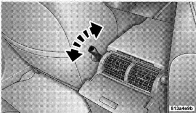
natural_image
Interior view of a car showing airflow direction arrows and a car grille (no text or symbols)ManualLumbarControl
8-WayDriver'sPowerSeat
The driver's power seat switches are located on the outboard side of the driver's seat lower side trim. The bottom switch controls up/down, forward/rearward, and tilt adjustment. The top switch controls the seatback recline adjustment.

natural_image
Interior view of a car seatbelt with a black arrow pointing to the seat area (no text or symbols visible)PowerSeatSwitches
4-WayPassenger'sPowerSeat—IfEquipped
The front passenger's power seat switches are located on the outboard side of the passenger seat lower side trim. The bottom switch controls forward/rearward adjustment. The top switch controls the seatback recline adjustment.
NOTE: The 4 - way seat does not have an up/down adjustment.
HeadRestraints
Head restraints can reduce the risk of whiplash injury in the event of impact from the rear. Adjustable head restraints should be adjusted so that the upper edge is as high as practical. The head restraints have a locking button which must be pushed in to lower the head restraint to all positions. The restraints may be raised without pushing in the button.

natural_image
Interior view of a car cockpit with steering wheel and dashboard (no visible text or symbols)AdjustableHeadRestraints
HeatedSeats—IfEquipped
Heated seats provide comfort and warmth on cold days and can help soothe sore muscles and backs. The heaters provide the same heat level for both cushion and back. The front driver and passenger seats are heated. The controls for each heater are located near the bottom
104UNDERSTANDINGTHEFEATURESOFYOURVEHICLE
center of the instrument panel. After turning on the ignition, you can choose from High, Off, or Low heat settings. Amber LEDs in the top portion of each switch indicate the level of heat in use. Two LEDs are illuminated for high, one for low, and none for off. Pressing the switch once will select high-level heating.

natural_image
Top-down view of a car dashboard with multiple dials and control buttons (no readable text or symbols)HeatedSeatSwitches
Pressing the switch a second time will select low-level heating. Pressing the switch a third time will shut the heating elements off.
When high-temperature heating is selected, the heaters provide a boosted heat level during the first four minutes of operation after heating is activated. The heat output then drops to the normal high-temperature level. If high-level heating is selected, the system will automatically switch to the low level after 30 minutes of continuous operation. At that time, the number of illuminated LEDs changes from two to one, indicating the change. Operation on the low setting also turns off automatically after 30 minutes.
NOTE: Once a heat setting is selected, heat will be felt within two to five minutes.
UNDERSTANDINGTHEFEATURESOFYOURVEHICLE105
WARNING!
Persons who are unable to feel painted the skin because of advanced age, chronic illness, diabetes, spinal cord injury, medication, alcohol use, exhaustion or other physical condition must exercise care when using these theaters. It may cause burn seven at low temperatures, especially if used for long period so time.
Donotplaceanythingontheseatthatinsulates againstheat,suchasablanketorcushion.Thismay causetheseatheatertooverheat.
60/40SplitRearSeat
To Lower Rear Seat
Either side of the rear seat can be lowered to allow for extended cargo space and still maintain some rear seating room.
NOTE: Be sure that the front seats are fully upright and positioned forward. This will allow the rear seatback to fold down easily.
- Pull the release strap (toward the front of the vehicle) to release.

natural_image
Mechanical component diagram showing a highlighted section with an arrow, no visible text or symbolsRearSeatRelease
106UNDERSTANDINGTHEFEATURESOFYOURVEHICLE
NOTE: Donotfold therearseatdownwith thecenter seatbeltbuckled.
- Fold the rear seat completely forward.
NOTE: The automatic folding rear head restraints will lower as the seat is folded down.

natural_image
Interior view of a car showing the rear seat, dashboard, and seatbelt (no visible text or symbols)FoldingRearSeat
To Raise Rear Seat
Raise the rear seatback and lock it into place. If interference from the cargo area prevents the seatback from fully locking, you will have difficulty returning the seat to its proper position. The automatic folding rear head restraints must be manually returned from the folded position to the raised seating position.
WARNING!
The cargo are in therear of the vehicle (with the rearseatbacks in the locked-up or folded down position) should not be used as a play area by children when the vehicle is in motion. They could be seriously injured in an accident. Children should be seated and using the proper restraint system.
UNDERSTANDINGTHEFEATURESOFYOURVEHICLE107
Storage—RearSeatArmrest(IfEquipped)
The rear seat may be equipped with a center storage armrest.

natural_image
Interior view of a car seatbelt with belt buckle and seat, showing no text or symbolsRearSeatArmrest
Press the latch and lift the top of the armrest to access the storage bin.

natural_image
Interior view of a car seatbelt with a black arrow pointing to the seat (no text or symbols visible)ArmrestStorageBin
DRIVERMEMORYSEAT—IFEQUIPPED
Once programmed, the memory buttons 1 and 2 on the driver's door panel can be used to recall the driver's seat, driver's outside mirror, adjustable brake and accelerator pedals, and radio station preset settings. Your Remote
Keyless Entry transmitters can also be programmed to recall the same positions when the "Unlock" button is pressed.

DriverMemorySwitches
Your vehicle may have been delivered with two Remote Keyless Entry transmitters. One or both transmitters can be linked to either memory position. The memory system can accommodate up to four transmitters, each one linked to either of the two memory positions.
SettingMemoryPositionsandLinkingRemote KeylessEntryTransmittertoMemory
NOTE: Each time the SET (S) button and a numbered button (1 or 2) are pressed, you erase the memory settings for that button and store a new one.
- Insert the ignition key and turn the ignition switch to the ON position.
- Press the driver door memory button number 1 if you are setting the memory for driver 1, or button number 2 if you are setting the memory for driver 2. The system will recall any stored settings. Wait for the system to complete the memory recall before continuing to step 3.
-
Adjust the driver's seat, recliner, and driver's side view mirror to the desired positions.
-
Adjust the brake and accelerator pedals to the desired positions.
- Turn on the radio and set the radio station presets (up to 10 AM and 10 FM stations can be set).
- Turn the ignition switch to the OFF position and remove the key.
- Press and release the SET (S) button located on the driver's door.
- Within 5 seconds, press and release memory button 1 or 2 on the driver's door. The next step must be performed within 5 seconds if you desire to also use a Remote Keyless Entry transmitter to recall memory positions.
-
Press and release the "Lock" button on one of the transmitters.
-
Insert the ignition key and turn the ignition switch to the ON position.
- Select "Remote Linked to Memory" in the Electronic Vehicle Information Center (EVIC) and enter "Yes" or select "Use Factory Settings" from the EVIC and enter "Yes". Refer to "Electronic Vehicle Information Center (EVIC) — Customer Programmable Features" in Section 4 for more information.
- Repeat the above steps to set the next memory position using the other numbered memory button or to link another Remote Keyless Entry transmitter to memory.
MemoryPositionRecall
NOTE: The vehicle must be in Park to recall memory positions. If a recall is attempted when the vehicle is not in Park, a message will be displayed in the Electronic Vehicle Information Center (EVIC).
110UNDERSTANDINGTHEFEATURESOFYOURVEHICLE
To recall the memory settings for driver one, press memory button number 1 on the driver's door or the "Unlock" button on the Remote Keyless Entry transmitter linked to memory position 1.
To recall the memory setting for driver two, press memory button number 2 on the driver's door or the "Unlock" button on the Remote Keyless Entry transmitter linked to memory position 2.
A recall can be cancelled by pressing any of the memory buttons on the drivers door during a recall (S, 1, or 2). When a recall is cancelled, the driver's seat, driver's mirror, and the pedals stop moving. A delay of one second will occur before another recall can be selected.
ToDisableATransmitterLinkedtoMemory
- Turn the ignition switch to the OFF position and remove the key.
- Press and release memory button number 1. The system will recall any memory settings stored in position
- Wait for the system to complete the memory recall before continuing to step 3.
- Press and release the memory SET (S) button located on the driver's door.
- Within 5 seconds, press and release memory button 1 on the driver's door.
- Within 5 seconds, press and release the "Unlock" button on the Remote Keyless Entry transmitter.
To disable another transmitter linked to either memory position, repeat steps 1-5 for each transmitter.
NOTE: Once programmed, all transmitters linked to memory can be easily enabled or disabled at one time. Refer to Remote Linked to Memory under "Electronic Vehicle Information Center (EVIC) — Customer Programmable Features" in Section 4 for more information.
EasyEntry/ExitSeat
This feature provides automatic driver's seat positioning which will enhance driver mobility out of and into the vehicle.
There are two possible Easy Exit and Easy Entry adjustments available:
- The seat cushion will move rearward approximately 2.5 inches (60 mm) if the starting position of the seat is greater than or equal to 2.67 inches (68 mm) forward of the rear seat stop when the key is removed from the ignition switch. The seat will then move forward
UNDERSTANDINGTHEFEATURESOFYOURVEHICLE111
approximately 2.5 inches (60 mm) when the key is placed into the ignition and turned out of the LOCK position.
- The seat shall move to the position located 0.3 inches (8 mm) forward of the rear stop if the starting position is between 0.9 inches to 2.67 inches (23 mm to 68 mm) forward of the rear stop when the key is removed from the ignition switch. The seat will move forward to the memory/driving position when the key is placed into the ignition, and turned out of the LOCK position toward the RUN position.
The Easy Entry/Easy Exit feature will be automatically disabled if the seat is already positioned closer than 0.9 inches (23 mm) forward of the rear stop. At this position there is no benefit to the driver by moving the seat for Easy Exit or Easy Entry.
112UNDERSTANDINGTHEFEATURESOFYOURVEHICLE
Each stored memory setting will have an associated Easy Entry and Easy Exit position.
NOTE: The Easy Entry Easy Exit feature is not enabled when the vehicle is delivered from the factory. The Easy Entry Easy Exit feature is enabled (or later disabled) through the programmable features in the Electronic Vehicle Information Center (EVIC). Refer to "Electronic Vehicle Information Center (EVIC) — Customer Programmable Features" in Section 4 for more information.
TOOPENANDCLOSETHEHOOD
To open the hood, pull the release lever inside your vehicle located below the instrument panel and in front of the driver's door.

natural_image
Interior view of a car showing the side panel, dashboard, and seatbelt (no text or symbols visible)HoodReleaseLever
UNDERSTANDINGTHEFEATURESOFYOURVEHICLE113
Then, reach under the hood, move safety latch to the left, and lift the hood. To prevent possible damage, do not slam the hood to close it. Use a firm downward push at the center of the hood to ensure that both latches engage.

natural_image
Front view of a car with a black arrow pointing right on the grille (no text or symbols)UnderhoodSafetyLatch
8167d09c
WARNING!
If the hood is not fully latched, it could fly up when the vehicle is moving and block your forward vision. Besure all hood latches are fully latched before driving.
114UNDERSTANDINGTHEFEATURESOFYOURVEHICLE
LIGHTS
Multi-FunctionControlLever
The multi-function control lever controls the operation of the headlights, turn signals, headlight beam selection, instrument panel light dimming, passing light, interior courtesy/dome lights, and optional fog lights.

natural_image
Interior view of a car dashboard with steering wheel and dashboard gauges (no visible text or symbols)Multi-FunctionControlLever
BatterySaverFeature—Exterior/InteriorLights
If the multi-function control lever is left in the interior light position, parking light position, or the headlight position when the ignition switch is moved to the OFF position, the battery saver feature will automatically turn off the exterior and interior lights after eight minutes. Normal operation will resume when the ignition is turned ON or when the headlight switch is turned to another position.
UNDERSTANDINGTHEFEATURESOFYOURVEHICLE115
HeadlightsandParkingLights
Turn the end of the multi-function control lever to the first detent for parking light operation. Turn to the second detent for headlight operation. Turn to the third detent for "Auto" headlight operation (if equipped).

natural_image
Interior view of a car dashboard with a rotary touchscreen device and directional arrows indicating rotation (no text or symbols on the device itself)HeadlightSwitch
AutomaticHeadlightSystem—IfEquipped
Turn the end of the multi-function control lever to the third detent to activate the automatic headlight system.
This system performs two functions. With the engine running and the multi-function control lever in the A (Auto) position, the headlights will turn on and off based on the surrounding light levels.
HeadlightsOnAutomaticallyWithWipers
If your vehicle is equipped with Automatic Headlights it also has this customer programmable feature. When your headlights are in the automatic mode, and the engine is running, they will automatically turn on when the wiper system is on.
If your vehicle is equipped with a “Rain Sensitive Wiper System,” and it is activated, the headlights will automatically turn on after the wipers complete five wipe cycles within approximately 1 minute, and they will turn off approximately four minutes after the wipers completely stop. Refer to “Windshield Wipers and Washers” in this section for more information.
NOTE: When your headlights come on during the daytime, the instrument panel lights will automatically dim to the lower nighttime intensity. Refer to "Instrument Panel and Interior Lights" below for setting the instrument panel lights to full daytime intensity.
SmartBeams—IfEquipped
The SmartBeam system provides increased forward lighting at night by automating high beam control through the use of a digital camera mounted on the inside rearview mirror. This camera detects vehicle specific light and automatically switches from high beams to low beams until the approaching vehicle is out of view.
NOTE: If the windshield or SmartBeam mirror is replaced, the SmartBeam mirror must be re-aimed to ensure proper performance. See your local authorized dealer.
ToActivate
- Select "Auto Headlamp Low/High Beams? — Low/High Beam." Refer to "EVIC — Customer Programmable Features" in Section 4 of this manual.
- Turn the end of the multi-function control lever to the A (Auto) headlight position.
NOTE: This system will not activate until the vehicle is at or above 20 mph (32 km/h).
ToDeactivate
- Pull back on the muti-function control lever to manually deactivate the system (normal operation of high beams).
- Pull back on the multi-function control lever once again to re-activate the system.
NOTE: Broken, muddy, or obstructed headlights and taillights of vehicles in the field of view will cause headlights to remain on longer (closer to the vehicle). Also, dirt, film, and other obstructions (sticker, toll box, etc.) on the windshield or camera lens will cause the system to function improperly.
InstrumentPanelandInteriorLights
When the multi-function control lever is in the parklight, headlight, or A (Auto) position (if equipped), rotating the center portion of the lever up and down will increase and decrease the brightness (dimmer control) of the instrument panel lights. Full daytime brightness on all electronic displays (odometer, overhead console, radio, and Automatic Climate Control (if equipped) is obtained by rotating the center portion of the control to the first detent above the dimmer range. Rotating the control to the second detent above the dimmer range turns the interior lights on. Rotating the control to the "Off" (extreme bottom) position disables all the interior lights, even when the doors and liftgate are open. While in the "Off" position the instrument panel lighting is at the lowest light level and may not be suitable for night driving.
DaytimeRunningLights—IfEquipped
The high beam headlights come on at a low intensity level whenever the engine is running, and the transmission in not in the P (Park) position. The lights remain on
until the ignition switch is turned OFF or the parking brake is engaged. The headlight switch must be used for normal night time driving.
Lights-OnReminder
If the headlights or parking lights are on after the ignition is turned OFF, a chime will sound when the driver's door is opened.
FogLights—IfEquipped
0 The fog light switch is located in the multifunction control lever. To activate the fog lights, turn on the park/turn lights, low beam headlights, or "Auto" headlights and pull out the end of the multifunction control lever. A light in the instrument cluster shows when the fog lights are on.
NOTE: Turning on the high beam headlights turns off the fog lights.
A front fog light is a lighting device providing illumination forward of the vehicle under conditions of fog, rain, snow, or dust. Principally, the front fog light supplements the lower beam of a standard headlight system.
NOTE: Proper aim and adjustments of the front fog lights should be made to prevent excessive glare for other drivers.
TurnSignals
Move the multi-function control lever up or down and the arrows on each side of the instrument cluster will flash to show proper operation of the front and rear turn signal lights. You can signal a lane change by moving the lever partially up or down.
TurnSignalAuto-Mode
Tap the multi-function control lever once and the turn signal (left or right) will flash 3 times, and automatically turn off.
UNDERSTANDINGTHEFEATURESOFYOURVEHICLE119
HighBeamSwitch
Pull the multi-function control lever towards you to switch the headlights to "High" beam. The "High Beam Indicator Light" on the instrument cluster will illuminate. Pull the multi-function control lever a second time to switch the headlights to "Low" beam.
PassingLight
You can signal another vehicle with your headlights by lightly pulling the multi-function control lever toward the steering wheel. This will cause the headlights to turn on at high beam and remain on until the lever is released.
HeadlightTimeDelay
There is also a feature that delays turning off the vehicle lights for 30, 60, or 90 seconds after the ignition switch is turned OFF. To activate the headlight delay, the multifunction control lever must be rotated to the "Off" position after the ignition switch is turned OFF. Only the headlights will illuminate during this time. Refer to "EVIC- Customer Programmable Features" in Section 4 to turn this feature "On/Off" or set the time interval.
InteriorLights
The interior lighting consists of courtesy lights mounted below the instrument panel, an overhead console light assembly which contains both driver and passenger reading lights, reading lights located above the rear doors, and a rear cargo light. Opening a door or turning the center of the multi-function control lever to the extreme up position will activate all interior courtesy lights.
120UNDERSTANDINGTHEFEATURESOFYOURVEHICLE
FrontMap/ReadingLights
These lights are mounted in the overhead console. Each light can be turned on by pressing the recessed area of the lens. To turn these lights off, press the recessed area of the lens a second time. There are also reading lights located above the rear doors. Each light can be turned on by pressing the front recessed area of the lens. To turn these lights off, press the recessed area of the lens a second time.

natural_image
Top-down view of a car backrest with air conditioner unit and directional arrows indicating airflow or movement (no text or symbols)813ac107
FrontMap/ReadingLights
UNDERSTANDINGTHEFEATURESOFYOURVEHICLE121
The front and rear wipers and washers are operated by a switch in the right side control lever. Turn the end of the control lever to select "Lo," "Hi," or one of the five speed sensitive intermittent windshield wiper speeds. Refer to "Speed Sensitive Intermittent Wiper System" in this section. For information on the rear wiper and washer, refer to "Rear Window Features" in this section.

natural_image
Interior view of a car dashboard and steering wheel (no visible text or symbols)WindshieldWiper/WasherSwitch
NOTE: Always remove any build-up of snow that prevents the windshield wiper blades from returning to the OFF position. If the windshield wiper switch is turned off and the blades cannot return to the OFF position, damage to the wiper motor may occur.
122UNDERSTANDINGTHEFEATURESOFYOURVEHICLE
To use the washer, pull the lever toward you and hold while spray is desired. If the lever is pulled while in the delay range, the wiper will operate for several seconds after the lever is released, and then resume the intermittent interval previously selected.
If the lever is pulled while in the OFF position, the wipers will operate for several wipe cycles, then turn off.
WARNING!
Suddenlossofvisibilitythroughthewindshield couldleadtoanaccident.Youmightnotseeother vehiclesorotherobstacles.Toavoidsuddenicingof thewindshieldduringfreezingweather,warmthe windshieldwiththedefrosterbeforeandduring windshieldwasheruse.
Mist
Use this feature when weather conditions make occasional usage of the wipers necessary. Pull down and release the control lever for a single wiping cycle.
SpeedSensitiveIntermittentWiperSystem
Use one of the five intermittent wiper speeds when weather conditions make a single wiping cycle, with a variable pause between cycles, desirable. Turn the end of the lever to one of the five delay positions for the desired delay interval. The delay can be regulated from a maximum of approximately 18 seconds between cycles, to a cycle every 1/2 second.
NOTE: The wiper delay times depend on vehicle speed. If the vehicle is moving less than 10 mph (16 km/h), delay times will be doubled.
UNDERSTANDINGTHEFEATURESOFYOURVEHICLE123
RainSensingWipers—IfEquipped
This feature senses moisture on the windshield and automatically activates the wipers for the driver. The feature is especially useful for road splash or overspray from the windshield washers of the vehicle ahead. Rotate the end of the multi-function lever to one of five settings to activate this feature.
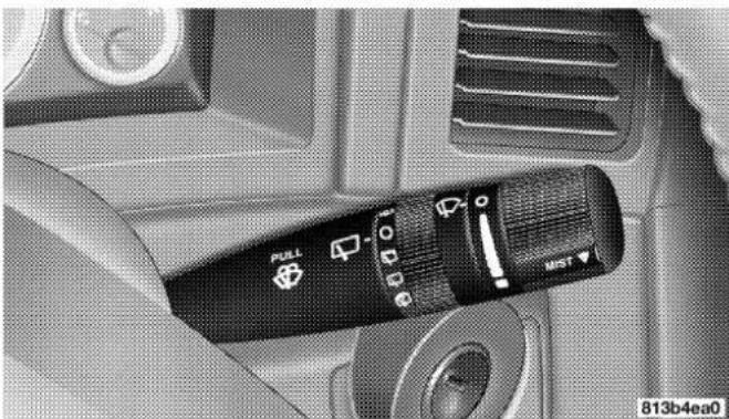
natural_image
Close-up of a black puller device with control buttons and a white 'MIST' label, mounted on a vehicle interior (no readable text beyond labels)RainSensitiveWiperSwitch
The sensitivity of the system can be adjusted with the multi-function lever. Wiper delay position 1 is the least sensitive, and wiper delay position 5 is the most sensitive. Setting 3 should be used for normal rain conditions. Settings 1 and 2 can be used if the driver desires less wiper sensitivity. Settings 4 and 5 can be used if the driver desires more sensitivity. Place the wiper switch in the OFF position when not using the system.
NOTE:
- The rain sensing feature will not operate when the wiper switch is in the LOW or HIGH speed position.
- The rain sensing feature may not function properly when ice, or dried salt water is present on the windshield.
- Use of Rain-X® or products containing wax or silicone may reduce rain sensor performance.
124UNDERSTANDINGTHEFEATURESOFYOURVEHICLE
- A customer programmable feature in the Electronic Vehicle Information Center (EVIC) allows the Rain Sense feature to be turned off. Refer to “Electronic Vehicle Information Center (EVIC)” in Section 4 of this manual.
The rain sensing system has protection features for the wiper blades and arms, and will not operate under the following conditions:
- LowAmbientTemperature— When the ignition is first turned ON, the rain sensing system will not operate until the wiper switch is moved, vehicle speed is greater than 0 mph (0 km/h), or the outside temperature is greater than 32°F (0°C).
- TransmissioninN(Neutral)Position—When the ignition is ON, and the transmission is in the N (Neutral) position, the rain sensing system will not operate until the wiper switch is moved, vehicle speed is greater than 5 mph (8 km/h), or the shift lever is moved out of the N (Neutral) position.
UNDERSTANDINGTHEFEATURESOFYOURVEHICLE125
TILTSTEERINGCOLUMN
To tilt the column, push down on the lever below the turn signal control and move the wheel up or down, as desired. Pull the lever back towards you and firmly push the lever until it is above the lower surface of the shroud to lock the column in place.
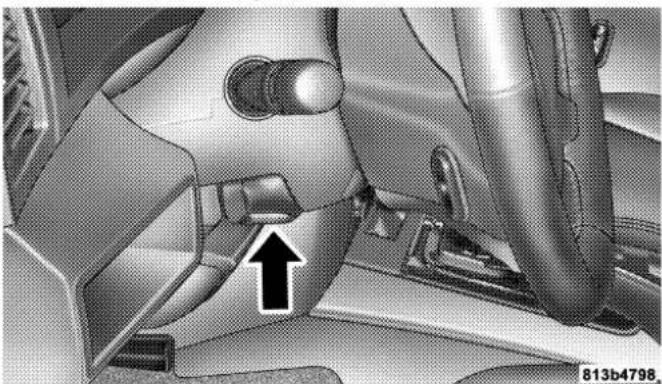
natural_image
Close-up of a car's front and side panels showing engine compartment, no visible text or symbolsTiltSteeringColumn
WARNING!
Tiltingthesteeringwheelcolumnwhilethevehicle ismovingisdangerous.Withoutastablesteering column,youcouldlosecontrolofthevehicleand haveanaccident.Adjustthetiltingmechanismonly whilethevehicleisstopped.Besureitislocked beforedriving.
126UNDERSTANDINGTHEFEATURESOFYOURVEHICLE
ADJUSTABLEPEDALS—IFEQUIPPED
This feature allows both the brake and accelerator pedals to move toward the driver to provide improved position with the steering wheel. The adjustable pedal system is designed to allow a greater range of driver comfort for steering wheel tilt and seat position. The position of the brake and accelerator pedals can be adjusted without compromising safety or comfort in actuating the pedals.
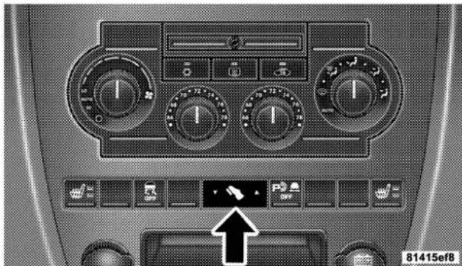
natural_image
Interior view of a car dashboard with multiple gauges and control buttons (no readable text or symbols)AdjustablePedalSwitch
UNDERSTANDINGTHEFEATURESOFYOURVEHICLE127
Press the left side of the button to move the pedals rearward (toward the driver).
Press the right side of the button to move the pedals forward (away from the driver).
- The pedals can be adjusted with the ignition OFF.
- The pedals can be adjusted while driving.
- The pedals cannot be adjusted when the vehicle is in R (Reverse) or when the Speed Control is ON. A message will be displayed in the Electronic Vehicle Information Center (EVIC) if the pedals are attempted to be adjusted when the system is locked out (“Adjustable Pedal Disabled — Cruise Control Engaged” or “Adjustable Pedal Disabled — Vehicle In Reverse”). Refer to Electronic Vehicle Information Center (EVIC) in Section 4 for more information.
CAUTION!
Donotplaceanyarticleundertheadjustablepedal's orimpedeitsabilitytomoveasitmaycausedamage tothepedalcontrols.Pedaltravelmaybecome limitedifmovementisstoppedbyanobstructionin theadjustablepedal'spath.
128UNDERSTANDINGTHEFEATURESOFYOURVEHICLE
ELECTRONICSPEEDCONTROL
When engaged, this device takes over accelerator operations at speeds greater than 25 mph (40 km/h). The controls are mounted on the steering wheel and consist of ON·OFF, SET, RES·ACCEL, CANCEL, and DECEL controls.

ToActivate
Press the ON·OFF button to turn the system ON. To turn the system OFF, press the ON·OFF button again. The system should be turned OFF when not in use. The CRUISE indicator light in the instrument cluster will illuminate when the system is ON.
ToSetataDesiredSpeed
When the vehicle has reached the desired speed, press and release the SET button. Release the accelerator and the vehicle will operate at the selected speed.
ToDeactivate
A soft tap on the brake pedal, normal braking, or pressing the CANCEL button will deactivate the Speed Control without erasing the memory. Pressing the ON-OFF to turn the system OFF or turning off the ignition erases the memory.
ToResumeSpeed
To resume a previously set speed, press and release the RES-ACCEL button. Resume can be used at any speed above 25 mph (40 km/h).
ToVarytheSpeedSetting
When the Speed Control is ON, speed can be increased by pressing and holding the RES-ACCEL button. When the button is released, a new set speed will be established.
Tapping the RES-ACCEL button once will result in a 1 mph (2 km/h) speed increase. Each time the button is tapped, speed increases, so tapping the button three times will increase speed by 3 mph (5 km/h), etc.
To decrease speed while Speed Control is ON and SET, press and hold the DECEL button. Release the button when the desired speed is reached, and the new speed will be set.
ToAccelerateforPassing
Depress the accelerator as you would normally. When the pedal is released, the vehicle will return to the set speed.
NOTE: When driving uphill, at elevations above 2,000 feet (610 meters), or when the vehicle is heavily loaded (especially when towing) the vehicle may slow below the SET speed. If the vehicle speed drops below 25 mph (40 km/h), the Speed Control will automatically disengage. If this happens, you can push down on the accelerator pedal to maintain the desired speed.
WARNING!
LeavingtheSpeedControlONwhennotinuseis dangerous.Youcouldaccidentallysetthesystemor causeittogofasterthanyouwant.Youcouldlose controlandhaveanaccident.Alwaysleavethe systemOFFwhenyouaren'tusingit.
130UNDERSTANDINGTHEFEATURESOFYOURVEHICLE
DrivingUporDownHills
When going up or down hills, it is possible for your vehicle to lose or gain speed, even though the Speed Control is engaged. The automatic transmission may also downshift to a lower gear, to maintain speed going up or down hills. If going down a hill steep enough to cause the vehicle to gain speed, press the brake pedal, which will disengage the Speed Control and help slow your vehicle.
WARNING!
To help keep your vehicle under control, donot use Speed Control under these conditions:
- When it is not possible to keep your vehicle at a set speed.
- On slippery roads, such as on snow or ice.
- In heavy or varying traffic volume, in traffic that varies in speed, or on winding roads.
- Be sure to turn the Speed Control switch to the OFF position when not in use to avoid accidental engagement.
ELECTRONICBRAKECONTROLSYSTEM
Your vehicle is equipped with an advanced electronic brake control system that includes ABS (Anti-Lock Brake System), TCS (Traction Control System), BAS (Brake Assist System), ERM (Electronic Roll Mitigation), and ESP (Electronic Stability Program). All five systems work together to enhance vehicle stability and control in various driving conditions, and are commonly referred to as ESP.
ABS(Anti-LockBrakeSystem)
This system aids the driver in maintaining vehicle control under adverse braking conditions. The system controls hydraulic brake pressure to prevent wheel lock-up and help avoid skidding on slippery surfaces during braking. Refer to “Anti-Lock Brake System” in Section 5 of this manual for more information about ABS.
WARNING!
ABS(Anti-LockBrakeSystem) cannot prevent the naturallawsofphysicsfromactingonthevehicle, norcanitincreasethetractionaffordedbyprevailingroadconditions.ABScannotpreventaccidents, includingthoseresultingfromexcessivespeedin turns,drivingonveryslipperysurfaces,orhydroplaning.Onlyasafe,attentive,andskillfuldriver canpreventaccidents.ThecapabilitiesofanABS-equippedvehiclemustneverbeexploitedinarecklessordangerousmannerwhichcouldjeopardize theuser'ssafetyorthesafetyofothers.
TCS(TractionControlSystem)
This system monitors the amount of wheel spin of each of the driven wheels. If wheel spin is detected, brake pressure is applied to the slipping wheel(s) and engine power is reduced to provide enhanced acceleration and stability. A feature of the TCS system functions similar to a limited slip differential and controls the wheel spin across a driven axle. If one wheel on a driven axle is spinning faster than the other, the system will apply the brake of the spinning wheel. This will allow more engine torque to be applied to the wheel that is not spinning. This feature remains active even if TCS and ESP are in the "ESP Partial Off" mode. Refer to "ESP (Electronic Stability Program)" in this section.
BAS(BrakeAssistSystem)
The BAS is designed to optimize the vehicle's braking capability during emergency braking maneuvers. The system detects an emergency braking situation by sensing the rate and amount of brake application and then applies optimum pressure to the brakes. This can help reduce braking distances. The BAS complements the anti-lock brake system (ABS). Applying the brakes very quickly results in the best BAS assistance. To receive the benefit of the system, you must apply continuous braking pressure during the stopping sequence. Do not reduce brake pedal pressure unless braking is no longer desired. Once the brake pedal is released, the BAS is deactivated.
WARNING!
BAS(BrakeAssistSystem) cannot prevent then natural law so of physics from acting on the vehicle, nor can it increase the traction afforded by prevailing road conditions. BAS cannot prevent accidents, including those resulting from excessives speed in turns, driving on very slippery surfaces, or hydroplaning. Only as safe, attentive, and skillful driver can prevent accidents. The capabilities of a BASE equipped vehicle must never be exploited in areckless or dangerous manner which could jeopardize the user's safety or the safety of others.
ERM(ElectronicRollMitigation)
This system anticipates the potential for wheel lift by monitoring the driver's steering wheel input and the speed of the vehicle. When ERM determines that the rate of change of the steering wheel angle and vehicles speed are sufficient to potentially cause wheel lift, it applies the appropriate brake and may reduce engine power to lessen the chance that wheel lift will occur. ERM will only intervene during very severe or evasive driving maneuvers.
ERM can only reduce the chance of wheel lift occurring during severe or evasive driving maneuvers. It cannot prevent wheel lift due to other factors such as road conditions, leaving the roadway or striking objects or other vehicles.
134UNDERSTANDINGTHEFEATURESOFYOURVEHICLE
WARNING!
Many factors, such as vehicle loading, road conditions and driving conditions, influence the chance that wheel liftor rollover may occur. ERM cannot prevent all wheel liftor rollovers, especially those that involve leaving the roadway or striking objects or other vehicles. Only as safe, attentive, and skillful driver can prevent accidents. The capabilities of an ERM-equipped vehicle must never be exploited in reckless dangerous manner which could jeopardize the user's safety or the safety of others.
ESP(ElectronicStabilityProgram)
This system enhances directional control and stability of the vehicle under various driving conditions. ESP corrects for over/under steering of the vehicle by applying
the brake of the appropriate wheel to assist in counter-acting the over/under steer condition. Engine power may also be reduced to help the vehicle maintain the desired path.
ESP uses sensors in the vehicle to determine the vehicle path intended by the driver and compares it to the actual path of the vehicle. When the actual path does not match the intended path, ESP applies the brake of the appropriate wheel to assist in counteracting the oversteer or understeer condition.
• Oversteer - when the vehicle is turning more than appropriate for the steering wheel position.
- Understeer - when the vehicle is turning less than appropriate for the steering wheel position.
The "ESP/TCS Indicator Light" located in the instrument cluster, starts to flash as soon as the tires lose traction and the ESP system becomes active. The "ESP/TCS Indicator
Light"also flashes when TCS is active. If the "ESP/TCS Indicator Light" begins to flash during acceleration, ease up on the accelerator and apply as little throttle as possible. Be sure to adapt your speed and driving to the prevailing road conditions.
WARNING!
ESP(ElectronicStabilityProgram) cannot prevent thenaturallawsofphysicsfromactingonthe vehicle,norcanitincreasethetractionaffordedby prevailingroadconditions.ESPcannotpreventaccidents,includingthoseresultingfromexcessive speedinturns,drivingonveryslipperysurfaces,or hydroplaning.Onlyasafe,attentive,andskillful drivercanpreventaccidents.Thecapabilitiesofan ESP-equippedvehiclemustneverbeexploitedina recklessordangerousmannerwhichcouldjeopardizetheuser'ssafetyorthesafetyofothers.
The ESP system has 2 available operating modes.
On
This is the normal operating mode for ESP. Whenever the vehicle is started, the ESP system will be in this mode. This mode should be used for most all driving situations. ESP should only be turned to "Partial Off" for specific reasons as noted below.
Partial Off
This mode is entered by momentarily depressing the "ESP Control Switch." When in "Partial Off" mode, the TCS portion of ESP, except for the "limited slip" feature described in the TCS section, has been disabled and the "ESP/TCS Indicator Light" will be illuminated. All other stability features of ESP function normally. This mode is intended to be used if the vehicle is in deep snow, sand, or gravel conditions and more wheel spin than ESP would normally allow is required to gain traction. To
136UNDERSTANDINGTHEFEATURESOFYOURVEHICLE
turn ESP on again, momentarily depress the "ESP Control Switch." This will restore the normal "ESP On" mode of operation.
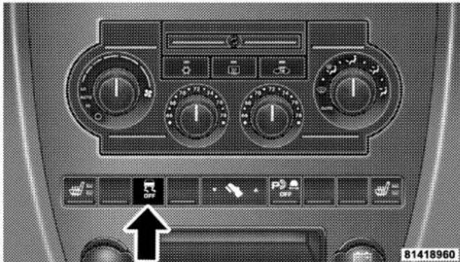
natural_image
Interior view of a car dashboard with multiple rotary controls and a control panel (no readable text or symbols)ESPControlSwitch
NOTE: To improve the vehicle's traction when driving with snow chains, or starting off in deep snow, sand, or gravel, it may be desirable to switch to the "ESP Partial Off" mode by pressing the ESP switch. Once the situation requiring ESP to be switched to the "ESP Partial Off" mode is overcome, turn ESP back on by momentarily depressing the "ESP Control Switch." This may be done while the vehicle is in motion.
ESP/BASWarningLampandESP/TCSIndicator Light
ESP BAS
The malfunction indicator lamp for the ESP is combined with the BAS indicator. The yellow "ESP/BAS Warning Lamp" and the yellow "ESP/TCS Indicator Light" in the instrument cluster both come on when the ignition switch is turned to the "ON" position. They should go out with the engine running.

If the "ESP/BAS Warning Lamp" comes on continuously with the engine running, a malfunction has been detected in either the ESP or the BAS system, or both. If this light remains on
after several ignition cycles, and the vehicle has been driven several miles at speeds greater than 30 mph (48 km/h), see your authorized dealer as soon as possible to have the problem diagnosed and corrected.
NOTE:
- "The "ESP/TCS Indicator Light" and the "ESP/BAS Warning Lamp" come on momentarily each time the ignition switch is turned ON.
- Each time the ignition is turned ON, the ESP System will be ON even if it was turned off previously.
- The ESP Control System will make buzzing or clicking sounds when it is active. This is normal; the sounds will stop when ESP becomes inactive following the maneuver that caused the ESP activation.
REARPARKASSISTSYSTEM—IFEQUIPPED
The Rear Park Assist System provides visual and audible indications of the distance between the rear fascia and the detected obstacle when backing up. Refer to the Warning Section and Note Section for limitations of this system and recommendations.
The Rear Park Assist System will remember the last system state (enabled or disabled) from the last ignition cycle when the ignition is changed to the RUN/ON position.
The Rear Park Assist System can be active only when the shifter is in R (Reverse). If the Rear Park Assist System is enabled at this shifter position, the system will be active until the vehicle speed is increased to approximately 11 mph (18 km/h) or above. The system will be active again if the vehicle speed is decreased to speeds less than approximately 10 mph (16 km/h).
138UNDERSTANDINGTHEFEATURESOFYOURVEHICLE
RearParkAssistSensors
The four Rear Park Assist Sensors, located in the rear fascia, monitor the area behind the vehicle that is within the sensors' field of view. The monitored area seems oval in shape.
The sensors can detect obstacles from approximately 11.8 inches (30 cm) up to 59 inches (150 cm) from the rear fascia in the horizontal direction, depending on the location and orientation of the obstacle and the type of obstacle.
RearParkAssistWarningDisplay
The Rear Park Assist Warning Display, located in the headliner near the flipper glass, provides both visual and audible warnings to indicate the distance between the rear fascia and the detected obstacle.
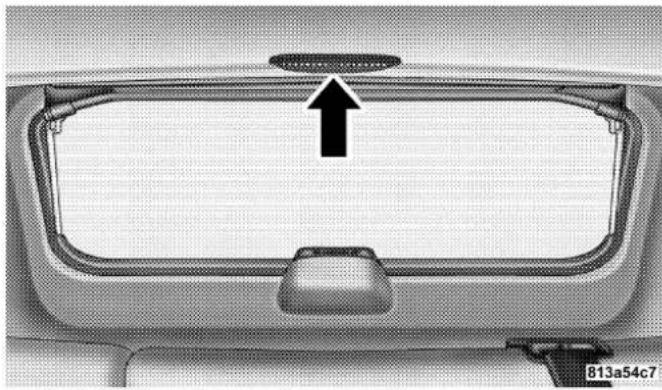
natural_image
Top-down view of a car's rearview rim with a black arrow pointing to the grille (no text or symbols)RearParkAssistDisplay
UNDERSTANDINGTHEFEATURESOFYOURVEHICLE139
When the ignition is changed to the RUN/ON position, the warning display will turn ON all of its LEDs for about 1 second. Each side of the warning display has 6 yellow and 2 red LEDs. The vehicle is close to the obstacle when the red LED is ON.
When the obstacle is detected at a distance of about 59 inches (150 cm) from the rear fascia, the outermost LEDs of the warning display will be ON with increased brightness. Along with the LED, a half second tone will occur. As the distance of the detected obstacle to the rear fascia decreases, more LEDs are illuminated. When the warning display has the first 5 yellow LEDs ON, the warning display will actuate an intermittent tone for about 10 seconds. The radio will be muted while the tone is actuated. The intermittent tone will increase in frequency as each additional LED is lit.
When the detected obstacle is about 11.8 inches (30 cm) from the rear fascia, the warning display will actuate a continuous tone for about 10 seconds, and it will turn ON all 8 LEDs, including both RED LEDs, on the corresponding side of the display. The radio will be muted while the tone is actuated.
When the obstacle is less than 11.8 inches (30 cm) from the rear fascia, the warning display will either have all 8 LEDs ON (obstacle detected) or it will have only the outermost LEDs ON with decreased brightness (obstacle not detected), depending on the location of the obstacle.
140UNDERSTANDINGTHEFEATURESOFYOURVEHICLE
Enable/DisabletheRearParkAssistSystem
The Rear Park Assist System can be enabled and disabled with a switch located in the switch bank of the instrument panel.
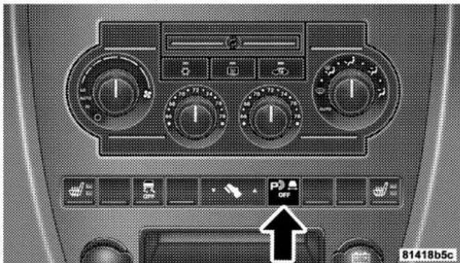
natural_image
Interior view of a car dashboard with air conditioners and control buttons (no readable text or symbols)RearParkAssistSwitch
When the switch is pressed to disable the system, the instrument cluster will display the "PARK ASSIST DISABLED" message. Refer to "Electronic Vehicle Information Center (EVIC)" in Section 4 of this manual. When the shifter is changed to R (Reverse) and the system is disabled, the instrument cluster will actuate a single chime, once per ignition cycle, and it will display the message.
The Rear Park Assist Switch LED will be ON when the Rear Park Assist System is disabled or defective. The Rear Park Assist Switch LED will be OFF when the system is enabled.
ServicetheRearParkAssistSystem
When the Rear Park Assist System is defective, the instrument cluster will actuate a single chime, once per ignition cycle, and it will display the "SERVICE PARK ASSIST SYSTEM" message. Refer to "Electronic Vehicle Information Center (EVIC)" in Section 4 of this manual.
CleaningtheRearParkAssistSystem
Clean the Rear Park Assist Sensors with water, car wash soap and a soft cloth. Do not use rough or hard cloths. Do not scratch or poke the sensors. Otherwise, you could damage the sensors.
CAUTION!
- TheRearParkAssistSystemisonlyaparkingaid anditisunabletorecognizeeveryobstacle,includingsmallobstacles.Parkingcurbsmightbe temporarilydetectedornotdetectedatall.Obstacleslocatedaboveorbelowthesensorswillnot bedetectedwhentheyareincloseproximity.
- The vehicle must bedrivenslowly when using the RearPark Assist System to be able to stop in time when the obstacle is detected. It is recommended that the driver looks over his / her shoulder when using the RearPark Assist System.
WARNING!
- Driversmustbecarefulwhenbackingupevenwhen usingtheRearParkAssistSystem.Alwayscheck carefullybehindyourvehicle,lookbehindyou,and besuretocheckforpedestrians,animals,other vehicles,obstructions,andblindspotsbeforebackingup.Youareresponsibleforsafetyandmust continuetopayattentiontoyoursurroundings.Failuretodosocanresultinseriousinjuryordeath.
- BeforeusingtheRearParkAssistSystem,itis stronglyrecommendedthattheballmountandhitch ballassemblyisdisconnectedfromthevehiclewhen thevehicleisnotusedfortowing.Failurertodoso canresultinjuryordamagetovehiclesorobstaclesbecausethehitchballwillbemuchcloserto theobstaclethantherearfasciawhenthewarning displayturnstheredLEDsON.Also,thesensors coulddetecttheballmountandhitchballassembly, dependingonitssizeandshape,givingafalse indicationthatanobstacleisbehindthevehicle.
NOTE: Clean all four Rear Park Assist Sensors regularly, taking care not to scratch or damage them. The sensors must not be covered with ice, snow, slush, mud, dirt or debris. Failure to do so can result in the system not working properly. The system might not detect an obstacle behind the fascia or it could provide a false indication that an obstacle is behind the fascia.
Assure objects are not within 11.8 inches (30 cm) from the rear fascia while driving the vehicle. Failure to do so can result in the system misinterpreting a close object as a sensor problem, causing the "SERVICE PARK ASSIST SYSTEM" message to be displayed in the instrument cluster.
Ultrasonic noise from airbrakes of nearby trucks, air powered jackhammers and air powered shop tools, to name a few, will cause the Rear Park Assist System to be disabled until the ultrasonic noise is no longer present.
REARCAMERA—IFEQUIPPED
Vehicles with a Navigation radio may be equipped with a rear view camera (located on the rear liftgate) that allows you to see an on-screen image (on the navigation radio screen) of the rear of your vehicle whenever the vehicle is put into R (Reverse).
WARNING!
Driversmustbecarefulwhenbackingupevenwhen usingtherearcamerasystem.Alwayscheckcarefullybehindyourvehicle,andbesuretocheckfor pedestrians,animals,othervehicles,obstructions,or blindspotsbeforebackingup.Failureretodosocan resultinseriousinjuryordeath.
If snow, ice, mud, or anything else builds up on the camera lens. Clean the lens, rinse with water, and dry with a soft cloth.
TurningtheRearCameraOn
- To access the rear camera mode, select "Rear Camera" at the Systems Settings screen and press ENTER. Refer to your "Navigation User's Manual" for detailed operating instructions.
- Select "ON" at the "Rear Camera" screen. Highlight "DONE" and press ENTER. The rear camera is now enabled.
- When the vehicle is shifted into R (Reverse), the CAUTION screen will appear, followed by an image of the rear of the vehicle.
- When the vehicle is shifted out of R (Reverse), the rear camera mode is exited and the Navigation or Audio screen appears again.
144UNDERSTANDINGTHEFEATURESOFYOURVEHICLE
TurningtheRearCameraOff
-
To turn the rear camera off, select "Rear Camera" at the Systems Settings screen and press ENTER. Refer to your "Navigation User's Manual" for detailed operating instructions.
-
Select "OFF" at the "Rear Camera" screen. Highlight "DONE" and press ENTER. The rear camera is now disabled.
OVERHEADCONSOLE
The overhead console contains courtesy/reading lights, an optional universal garage door opener (HomeLink®), storage for sunglasses, and optional power sunroof switches.
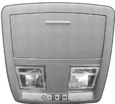
natural_image
Top-down view of a car ceiling panel with two side screens and control buttons (no visible text or symbols)OverheadConsole
8125e191
UNDERSTANDINGTHEFEATURESOFYOURVEHICLE145
Courtesy/ReadingLights
At the forward end of the console are two courtesy/reading lights.
Press the lens to turn these lights on. Press a second time to turn the lights off.
The lights also turn on when a front door or rear door is opened. The lights will also turn on when the unlock button on the remote keyless entry transmitter is pressed.
SunglassesStorage
At the rear of the console a compartment is provided for the storage of a pair of sunglasses.
The storage compartment access is a "push/push" design. Push the finger depression on the overhead console to open. Push the finger depression to close.
GARAGEDOOROPENER
The HomeLink®Universal Transceiver replaces up to three remote controls (hand held transmitters) that operate devices such as garage door openers, motorized gates, or home lighting. It triggers these devices at the push of a button. The Universal Transceiver operates off your vehicle's battery and charging system; no batteries are needed.
NOTE: The HomeLink® Universal Transceiver is disabled when the Vehicle Theft Alarm is active.
For additional information on HomeLink ® , call 1-800-355-3515, or on the internet at www.homelink.com.
146UNDERSTANDINGTHEFEATURESOFYOURVEHICLE
WARNING!
Amovinggaragedoorcancauseinjurytopeopleand petsinthepathofthedoor.Peopleorpetscouldbe seriouslyorfatallyinjured.Onlyusethistransceiver withagaragedooropenerthathasa"stopand reverse"featureasrequiredbyfederalsafetystandards.Thisincludesmostgaragedooropenermodelsmanufacturedafter1982.Donotuseagarage dooropenerwithoutthesesafetyfeaturesitcould causeinjuryordeath.Calltoll-free1-800-355-3515 or,ontheInternetatwww.homelink.comforsafety informationorassistance.
WARNING!
Vehicleexhaustcontainscarbonmonoxide,adangerousgas.Donotrunthevehicle'sexhaustwhile trainingthetransceiver.Exhaustgascancauseseriousinjuryordeath.
WARNING!
Yourmotorizeddoororgatewillopenandclose whileyouaretrainingtheUniversalTransceiver.Do nottrainthetransceiverifpeopleorpetsareinthe pathofthedoororgate.Amovingdoororgatecan causeseriousinjuryordeathtopeopleandpetsor damagetoobjects.
UNDERSTANDINGTHEFEATURESOFYOURVEHICLE147
ProgrammingHomeLink
NOTE: When programming a garage door opener, it is advised to park outside the garage. It is also recommended that a new battery be placed in the hand-held transmitter of the device being programmed to HomeLink for quicker training and accurate transmission of the radio-frequency signal.
The Electronic Vehicle Information Center (EVIC) features a driver-interactive display which includes HomeLink system messages. The EVIC is located on the bottom of the tachometer.
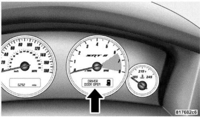
ElectronicVehicleInformationCenter
148UNDERSTANDINGTHEFEATURESOFYOURVEHICLE
- Press and hold the two outer HomeLink buttons, and release only when the EVIC display shows "CHANNELS CLEARED" (after 20 seconds). Donothold the buttons for longer than 30 seconds and donotrepeat step one to program a second and/or third hand-held transmitter to the remaining two HomeLink buttons.

natural_image
Top-down view of a car backrest with two monitors and directional arrows indicating navigation (no text or symbols)HomeLinkButtons
8125e19b
- Position the end of your hand-held transmitter 1-3 inches (3-8 cm) away from the HomeLink buttons.
- Simultaneously press and hold both the HomeLink button that you want to train and the hand-held transmitter buttons. Donotreleasethebuttonsuntilstep4 has been completed.
NOTE: Some gate operators and garage door openers may require you to replace this Programming Step 3 with procedures noted in the "Gate Operator/Canadian Programming" section.
- The EVIC display will show "CHANNEL X TRAINING" (where X is Channel 1, 2, or 3). Release both buttons after the EVIC display shows "CHANNEL X TRAINED."
NOTE: If the EVIC display shows "DID NOT TRAIN" repeat steps 2–4.
- Press and hold the just trained HomeLink button and observe the EVIC display. If the EVIC display shows "CHANNEL X TRANSMIT" (where X is Channel 1, 2, or 3), programming is complete and your device should activate when the HomeLink button is pressed and released.
NOTE: To program the remaining two HomeLink buttons, begin with "Programming" step two. Do not repeat stepone.
NOTE: If your hand-held transmitter appears to program the universal transceiver, but your garage door does not operate using the transmitter and your garage door opener was manufactured after 1995, your garage door opener may have a multiple security code system (rolling code system). Please proceed to steps 6–8 to complete the programming of a rolling code equipped device (most common garage door openers require this step.
- At the garage door opener receiver (motor-head unit) in the garage, locate the "learn" or "smart" button. This can usually be found where the hanging antenna wire is attached to the motor-head unit.
- Firmly press and release the "learn" or "smart" button. (The name and color of the button may vary by manufacturer.)
NOTE: There are 30 seconds in which to initiate step eight.
- Return to the vehicle and firmly press, hold for two seconds and release the programmed HomeLink button. Repeat the "press/hold/release" sequence a second time, and, depending on the brand of the garage door opener (or other rolling code equipped device), repeat this sequence a third time to complete the programming.
HomeLink should now activate your rolling code equipped device.
150UNDERSTANDINGTHEFEATURESOFYOURVEHICLE
NOTE: To program the remaining two HomeLink buttons, begin with "Programming" step two. Do not repeat stepone. For questions or comments, please contact HomeLink at www.homelink.comor1-800-355-3515.
CanadianProgramming/GateProgramming
Canadian radio-frequency laws require transmitter signals to "time-out"(or quit) after several seconds of transmission which may not be long enough for HomeLink to pick up the signal during programming. Similar to this Canadian law, some U.S. gate operators are designed to "time-out" in the same manner.
If you live in Canada or you are having difficulties programming a gate operator by using the "Programming" procedures (regardless of where you live), replace "Programming HomeLink" step 3 with the following:
NOTE: If programming a garage door opener or gate operator, it is advised to unplug the device during the "cycling" process to prevent possible overheating.
- Continue to press and hold the HomeLink button while you press and release every two seconds ("cycle") your hand-held transmitter until the frequency signal has successfully been accepted by HomeLink. The EVIC display will show "CHANNEL X TRAINED" (where X is Channel 1, 2, or 3). Proceed with "Programming" step four to complete.
UsingHomeLink
To operate, simply press and release the programmed HomeLink button. Activation will now occur for the trained device (i.e. garage door opener, gate operator, security system, entry door lock, home/office lighting, etc.). For convenience, the hand-held transmitter of the device may also be used at any time. In the event that there are still programming difficulties or questions, contact HomeLink at: www.homelink.comor1-800-355-3515.
UNDERSTANDINGTHEFEATURESOFYOURVEHICLE151
ErasingHomeLinkButtons
To erase programming from the three buttons (individual buttons cannot be erased but can be "reprogrammed"-note below), follow the step noted:
- Press and hold the two outer HomeLink buttons and release only when the EVIC display shows "CHANNELS CLEARED" (after 20 seconds). Release both buttons. Do not hold for longer that 30 seconds. HomeLink is now in the train (or learning) mode and can be programmed at any time beginning with "Programming"- Step 2.
ReprogrammingaSingleHomeLinkButton
To program a device to HomeLink using a HomeLink button previously trained, follow these steps:
-
Press and hold the desired HomeLink button. Do NOT release the button.
-
The EVIC display will show "CHANNEL X TRANSMIT" (where X is Channel 1, 2, or 3) for 20 seconds and then change to "CHANNEL X TRAINING." Without releasing the HomeLink button, proceed with "Programming" Step 2.
For questions or comments, contact HomeLink at: www.homelink.comor1-800-355-3515.
Security
If you sell your vehicle, be sure to erase the frequencies by following the "Erasing HomeLink Buttons" instructions in this section.
This device complies with part 15 of FCC rules and with RSS-210 of Industry Canada. Operation is subject to the following conditions:
- This device may not cause harmful interference.
152UNDERSTANDINGTHEFEATURESOFYOURVEHICLE
- This device must accept any interference that may be received including interference that may cause undesired operation.
NOTE: Changes or modifications not expressly approved by the party responsible for compliance could void the user's authority to operate the equipment.
HomeLink® is a trademark owned by Johnson Controls, Inc.
POWERSUNROOF—IFEQUIPPED
The power sunroof switch is located between the sun visors on the overhead console.

natural_image
Top-down view of a car's rearview and dashboard with a black arrow pointing to a control panel (no text or symbols visible)PowerSunroofSwitch
WARNING!
- Neverleavechildreninavehicle,withthekeysin theignitionswitch.Occupants,particularlyunattendedchildren,canbecomeentrappedbythe powersunroofwhileoperatingthepowersunroof switch.Suchentrapmentmayresultinserious injuryordeath.
- Inanaccident, thereisagreaterriskofbeing thrownfromvehiclewithanopensunroof. You couldalsobeseriouslyinjuredorkilled. Always fastenyourseatbeltproperlyandmakesureall passengersareproperlysecuredtoo.
- Donotallowsmallchildrentooperatethesun-roof.Neverallowfingersorotherbodyparts,or anyobjecttoprojectthroughthesunroofopening. Injurymayresult.
OpeningSunroof-Express
Press the switch rearward and release, and the sunroof will open automatically from any position. The sunroof will open fully, then stop automatically. This is called Express Open. During Express Open operation, any movement of the sunroof switch will stop the sunroof.
ClosingSunroof-Express
Press the switch forward and release, and the sunroof will close automatically from any position. The sunroof will close fully and stop automatically. This is called Express Close. During Express Close operation, any movement of the switch will stop the sunroof.
PinchProtectFeature
This feature will detect an obstruction in the opening of the sunroof during Express Close operation. If an obstruction in the path of the sunroof is detected, the
154UNDERSTANDINGTHEFEATURESOFYOURVEHICLE
sunroof will automatically retract. Remove the obstruction if this occurs. Next, press the switch forward and release to Express Close.
PinchProtectOverride
If a known obstruction (ice, debris, etc.) prevents closing, press the switch forward and hold for two seconds after the reversal occurs. This allows the sunroof to move towards the closed position.
NOTE: Pinch protection is disabled while the switch is pressed.
VentingSunroof-Express
Press and release the "V" button, and the sunroof will open to the vent position. This is called Express Vent, and will occur regardless of sunroof position. During Express Vent operation, any movement of the switch will stop the sunroof.
SunshadeOperation
The sunshade can be opened manually. However, the sunshade will open automatically as the sunroof opens.
NOTE: The sunshade cannot be closed if the sunroof is open.
WindBuffeting
Wind buffeting can be described as the perception of pressure on the ears or a helicopter type sound in the ears. Your vehicle may exhibit wind buffeting with the windows down, or the sunroof (if equipped) in certain open or partially open positions. This is a normal occurrence and can be minimized. If the buffeting occurs with the rear windows open, open the front and rear windows together to minimize the buffeting. If the buffeting occurs with the sunroof open, adjust the sunroof opening to minimize the buffeting or open any window.
UNDERSTANDINGTHEFEATURESOFYOURVEHICLE155
SunroofMaintenance
Use only a non-abrasive cleaner and a soft cloth to clean the glass panel.
IgnitionOffOperation
The power sunroof switches remain active for 10 minutes after the ignition switch has been turned off. Opening either front door will cancel this feature.
SunroofFullyClosed
Press the switch forward and release to ensure that the sunroof is fully closed.
POWEROUTLET
To the right of the convenience tray (lower center of instrument panel) is an outlet for electrically powered accessories. Pull lightly on the tab of the plastic cover to access the outlet.

natural_image
Interior view of a car dashboard with air conditioners and a control knob (no readable text or symbols)FrontPowerOutlet
156UNDERSTANDINGTHEFEATURESOFYOURVEHICLE
The rear power outlet (if equipped) is located in the left rear cargo area.

natural_image
Close-up of a mechanical component with a circular button labeled 'AIRS OUTLET' and an arrow pointing to it (no readable text or symbols beyond the label)RearPowerOutlet
The power outlets are a direct feed from the battery so they receive power whether the ignition is in the ON or OFF position.
All accessories connected to this outlet should be removed or turned off when the vehicle is not in use to protect the battery against discharge.
CAUTION!
ElectricalOutletUseWithEngineOff
- Manyaccessoriesthatcanbepluggedindraw powerfromthevehicle'sbattery,evenwhennot inuse(i.e.,cellularphones,etc.).Eventually,if pluggedinlongenough,thevehicle'sbatterywill dischargesufficientlytodegradebatterylife and/orpreventenginestarting.
- Accessories that draw higher power (i.e., coolers, vacuum cleaners, lights, etc.) will degrade the battery even more quickly. Only use these intermittently and with greater caution.
- Aftertheuseofhighpowerdrawaccessories,or longperiodsofthevehiclenotbeingstarted(with accessoriesstillpluggedin),thevehiclemustbe drivenasufficientlengthofttimetoallowthe generatortorechargethevehicle'sbattery.
CUPHOLDERS
In the center console there are two cup holders for the front seat passengers.

natural_image
Interior view of a car showing a car's gear shift lever and dashboard (no text or symbols visible)FrontCupHolders
158UNDERSTANDINGTHEFEATURESOFYOURVEHICLE
NOTE: The cup holder insert is removable, from the console, for cleaning. It can be reinstalled with the larger cup depression towards the passenger seat, but the top surface will not be flush with the console surface.
The rear passengers have access to two cup holders that pull out from the lower center of the rear seat.

natural_image
Interior view of a vehicle showing a cylindrical body with a handle and attached seat (no visible text or symbols)RearCupHolders
CARGOAREAFEATURES
CargoLight
The cargo area light is activated by opening the liftgate, opening any door, or by rotating the dimmer control on the multi-function control lever to the extreme top position. If all doors are closed and only the liftgate is open, pushing on the cargo light lens surface will turn off all interior lamps. Push on the lens surface a second time to restore the interior lights to normal operation.
UNDERSTANDINGTHEFEATURESOFYOURVEHICLE159
RearStorageCompartment
The rear storage compartment is located on the driver's side behind the second row seat.

natural_image
Interior view of a vehicle cabin with open door and structural panel (no visible text or symbols)RearStorageCompartment
RetractableCargoAreaCover
NOTE: The purpose of this cover is for privacy, not to secure loads. It will not prevent cargo from shifting or protect passengers from loose cargo.
To cover the cargo area:
-
Grasp the cover at the center handle. Pull it over the cargo area.
-
Insert the pins on the ends of the cover into the slots in the pillar trim cover.
160UNDERSTANDINGTHEFEATURESOFYOURVEHICLE
- The liftgate may be opened with the cargo cover in place.
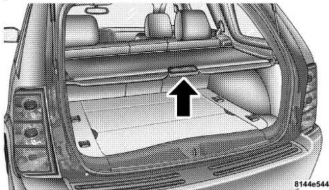
natural_image
Interior view of a car showing the rear compartment with a large open trunk and a black arrow pointing to the backrest area (no text or symbols present)RearCargoCover
WARNING!
Inanaccidentacargocoverlooseinthevehicle could cause injury. It could fly around in as sudden stop and strikes someone one in the vehicle. Donot store the cargocover on the cargofloor or in the passenger compartment. Removethecover from the vehicle whentaken from its mounting. Donot store in the vehicle.
UNDERSTANDINGTHEFEATURESOFYOURVEHICLE161
CargoTie-DownHooks
The tie-downs located on cargo area floor should be used to safely secure loads when vehicle is moving.

natural_image
Top-down view of a car backrest with three black arrows indicating directional flow or movement, no text or symbols present.CargoTie-DownHooks
WARNING!
Cargotie-downhooksarenotsafeanchorsfora childseattetherstrap.Inasuddenstoporcollision ahookcouldpullooseandallowthechildseatto comeloose.Achildcouldbebadlyinjured.Useonly theanchorsprovidedforchildseattethers.
WARNING!
Theweightandpositionofcargoandpassengerscan changethevehiclecenterofgravityandvehicle handling.Toavoidlossofcontrolresultinginpersonalinjury,followtheseguidelinesforloading yourvehicle:
162UNDERSTANDINGTHEFEATURESOFYOURVEHICLE
- Do not carry loads which exceed the load limits described on the label attached to the left door or left door center pillar.
- Always place cargo evenly on the cargo floor. Put heavier objects as low and as far forward as possible.
- Place as much cargo as possible in front of the rear axle. Too much weight or improperly placed weight over or behind the rear axle can cause the rear of the vehicle to sway.
- Do not pile luggage or cargo higher than the top of the seatback. This could impair visibility or become a dangerous projectile in a sudden stop or collision.
WARNING!
Tohelpprotectagainstpersonalinjury,passengers shouldnotbeseatedintherearcargoarea.Therear cargospaceisintendedforloadcarryingpurposes only,notforpassengers,whoshouldsitinseatsand useseatbelts.
UNDERSTANDINGTHEFEATURESOFYOURVEHICLE163
CargoLoadFloor
The panel in the load floor is reversible for added utility. One side is carpeted and the other side features a plastic lined tray which holds a variety of items.

natural_image
Top-down view of a car trunk with a black arrow pointing to the rear vent, showing structural components (no text or symbols)CargoLoadFloor
The cargo load floor is held by spring loaded latches. In order to use the cargo load floor, use the following procedure:
NOTE: The cargoloadfloorlatchess should not be used as cargotie - downs.
- Flip up pull loop(s) so they are perpendicular (straight up) to the top surface of the tray.
- Pull up on loop(s) and twist 90 degrees, so they are parallel to the slotted hole in tray.
- Lift tray over loop(s), and reposition tray.
- Pull up on loop(s) and twist 90 degrees, so they are perpendicular (straight up) to the slotted hole in tray.
- Push loop(s) back down, so they are parallel to the top of the tray.
164UNDERSTANDINGTHEFEATURESOFYOURVEHICLE
REARWINDOWFEATURES
RearWindowWiper/Washer—IfEquipped
A switch on the right side of the steering column controls operation of the rear wiper/washer function. Rotating the switch up to the DEL (Delay) position or the ON position will activate the wiper. Rotating the switch all the way up or down will turn on the wash function. The wash pump will continue to operate as long as the button is pressed. Upon release, the wipers will cycle three times before returning to the set position.

natural_image
Close-up of a black handheld device with 'PULL' and 'MIST' labels, resting on a car interior (no readable text beyond labels)RearWiper/WasherSwitch
If the rear wiper is operating when the ignition is turned OFF, the wiper will automatically return to the "Park" position.
UNDERSTANDINGTHEFEATURESOFYOURVEHICLE165
If the liftgate flipper glass is open, connection to the rear window wiper is interrupted preventing activation of the rear wiper blade. When the liftgate flipper glass is closed, the rear wiper switch or the ignition switch needs to be turned OFF and ON to restart the rear wiper.
AddingWasherFluid
The fluid reservoir for the windshield washers and the rear window washer is shared. It is located in the front of the engine compartment on the passenger side and should be checked for fluid level at regular intervals. Fill the reservoir with windshield washer solvent (not radiator antifreeze) and operate the system for a few seconds to flush out the residual water.
RearWindowDefroster—IfEquipped
Press this button (located on the Climate Control panel) to turn on the rear window defroster and the heated side mirrors (if equipped). An LED in the button will illuminate to indicate the rear window defroster is ON. The defroster automatically turns off after about 10 minutes of operation.
CAUTION!
To avoid damaging the electrical conductor of the rear window defroster, donotusescrapers, sharp instruments, or abrasivewindow cleanerson the interiorsurfaceofthewindow.
Labelscanbepeeledoffaftersoakingwithwarm water.
UNDERSTANDING YOUR INSTRUMENT PANEL
CONTENTS
■Instrument Panel And Controls....170
■Instrument Cluster ..... 171
■Instrument Cluster Description....172
■Electronic Vehicle Information Center ..... 1 7 9
□Customer Programmable Features....181
□Compass/Temperature/Trip Computer ..... 1 8 6
□Trip Computer....188
■Radio General Information....194
□Radio Broadcast Signals....194
□ Two Types Of Signals .....194
□ Electrical Disturbances .....194
□AM Reception 194
□FM Reception....195
■ Sales Code RAQ – AM/FM/CD (6-Disc) Radio With Optional Satellite Radio, Hands Free Phone, And Vehicle Entertainment Systems (VES)
Capabilities....195
□Operating Instructions - Radio Mode ..... 1 9 5
UNDERSTANDING YOUR INSTRUMENT PANEL
☐Operation Instructions - (CD Mode For CD Audio Play) ..... 2 0 1
□Load/Eject Button (CD Mode For CD Audio Play)....202
□Notes On Playing MP3 Files ..... 2 0 4
☐Operation Instructions - (CD Mode For MP3 Audio Play) ..... 2 0 7
□Load/Eject Button (CD Mode For MP3 Play) .. 207
■Sales Code REC — AM/FM/CD (6-Disc) Radio With Navigation System....209
□Operating Instructions — Satellite Radio (If Equipped) 210
□REC Setting The Clock....2 1 0
□Audio Clock Display....2 1 3
■Video Entertainment System (Sales Code XRV) — If Equipped....2 1 4
Satellite Radio — If Equipped ..... 2 1 6
□System Activation....216
□Electronic Serial Number/Sirius Identification Number (ESN/SID)....2 1 6
□Selecting Satellite Mode In RAQ Radios ..... 2 1 7
□Selecting a Channel....217
□Storing And Selecting Pre-Set Channels ..... 2 1 8
□Using The PTY (Program Type) Button — If Equipped 218
□ PTY Button "Scan" .....218
□ PTY Button "Seek" .....218
□Satellite Antenna....218
UNDERSTANDING YOUR INSTRUMENT PANEL 169
□Reception Quality....219
■Remote Sound System Controls....2 1 9
□Radio Operation....2 2 0
□CD Player....2 2 0
■CD/DVD Disc Maintenance ..... 2 2 1
■Radio Operation And Cellular Phones ..... 2 2 1
■Climate Controls....2 2 2
□Automatic Temperature Control....2 2 2
□Operating Tips....2 2 8
170UNDERSTANDINGYOURINSTRUMENTPANEL
INSTRUMENTPANELANDCONTROLS

- Air Outlet
- Instrument Cluster
- Horn
- Radio
- Glove Box
- Climate Controls
- Heated Seat Switch
- Power Outlet
- Rear Park Assist Switch
- Adjustable Pedals Switch
- Electronic Stability Control/
Traction Control System Switch - Auxiliary Power Outlet
- Ignition Switch
- Upper Switch Bank
817a6b83
INSTRUMENTCLUSTER

8179b714
172UNDERSTANDINGYOURINSTRUMENTPANEL
INSTRUMENTCLUSTERDESCRIPTION
1. Speedometer
Indicates vehicle speed.
2. Brake Warning Light

The BRAKE warning light will come on when the ignition is first turned on, and stay on briefly as a bulb check. If the bulb does not come on during starting, have the bulb repaired promptly. If the light stays on longer, it may be an indication that the parking brake has not been released.
If the light remains on when the parking brake is off, it indicates a possible brake hydraulic system malfunction or low fluid level. In this case, the BRAKE warning light will remain on until the cause is corrected. If a brake malfunction is indicated, immediate repair is necessary and continued operation of the vehicle in this condition is dangerous.
3. Turn Signal Indicator Light
The arrow will flash with the exterior turn signal when the turn signal lever is operated.
If the vehicle electronics sense that the vehicle has traveled about one mile with the turn signals on, a chime will sound to alert you to turn the signals off. If either indicator flashes at a rapid rate, check for a defective outside light bulb.
4. High Beam Indicator Light
ID Indicates that headlights are on high beam.
5. Malfunction Indicator Light
This light is part of an onboard diagnostic system called OBD II that monitors engine and automatic transmission control systems. The light will illuminate when the key is in the ON position before
engine start. If the bulb does not come on when turning the key from OFF to ON, have the condition checked promptly.
Certain conditions such as a loose or missing gas cap, poor fuel quality, etc. may illuminate the light after engine start. The vehicle should be serviced if the light stays on through several of your typical driving cycles. In most situations the vehicle will drive normally and will not require towing.
The Malfunction Indicator Light flashes to alert you to serious conditions that could lead to immediate loss of power or severe catalytic converter damage. The vehicle should be serviced as soon as possible if this occurs.
6. Airbag Warning Light

This light turns on and remains on for 6 to 8 seconds as a bulb check when the ignition switch is first turned ON. If the light is not on during starting, stays on, or turns on while driving, have the system inspected by an authorized dealer as soon as possible.
7. Anti-Lock Brake Warning Light

This light monitors the Anti-Lock Brake System. The light will turn on when the ignition switch is l to the ON position and may stay on for as long as seconds.
If the ABS light remains on or turns on while driving, it indicates that the Anti-Lock portion of the brake system is not functioning and that service is required. However, the conventional brake system will continue to operate normally if the BRAKE warning light is not on.
If the ABS light is on, the brake system should be serviced as soon as possible to restore the benefits of Anti-Lock brakes. If the ABS light does not turn on when the Ignition switch is turned to the ON position, have the light inspected by an authorized dealer.
8. Tachometer
The red segments indicate the maximum permissible engine revolutions-per-minute (r.p.m. x 1000) for each gear range. Before reaching the red area, ease up on the accelerator.
9. Security Alarm System Indicator Light — If Equipped
This light will flash rapidly for approximately 15 seconds when the vehicle theft alarm is arming. The light will flash at a slower speed continuously after the alarm is set. The security light will also come on for about three seconds when the ignition is first turned on.
10. Oil Pressure Warning Light

This light shows low engine oil pressure. The light should turn on momentarily when the engine is started. If the light turns on while driving, stop the vehicle, and shut off the engine as soon as possible. A continuous chime will sound when this light turns on.
Do not operate the vehicle until the cause is corrected. This light does not show how much oil is in the engine. The engine oil level must be checked under the hood.
11. Electronic Stability Program (ESP) Indicator Light/Traction Control System (TCS) Indicator Light

This indicator light starts to flash as soon as the tires lose traction and the ESP system becomes active. The "ESP/TCS Indicator Light" also flashes when TCS is active. If the "ESP/TCS Indicator Light" begins to flash during acceleration, ease up on the accelerator and apply as little throttle as possible. Be sure to adapt your speed and driving to the prevailing road conditions. The "ESP/TCS Indicator Light" will flash any time the ESP or TCS is active and helping to improve vehicle stability. If the "ESP/TCS Indicator Light" is on solid, the ESP system has been turned off by the driver or a temporary condition exists that will not allow full ESP function.
12. Tire Pressure Monitoring Telltale Light

Each tire, including the spare (if provided), should be checked monthly when cold and inflated to the inflation pressure recommended by the vehicle manufacturer on the vehicle placard or tire inflation pressure label. (If your vehicle has tires of a different size than the size indicated on the vehicle placard or tire inflation pressure label, you should determine the proper tire inflation pressure for those tires.)
As an added safety feature, your vehicle has been equipped with a tire pressure monitoring system (TPMS) that illuminates a low tire pressure telltale when one or more of your tires is significantly under-inflated. Accordingly, when the low tire pressure telltale illuminates, you should stop and check your tires as soon as possible, and inflate them to the proper pressure. Driving on a significantly under-inflated tire causes the tire to overheat and can lead to tire failure. Under-inflation also reduces fuel efficiency and tire tread life, and may affect the vehicle's handling and stopping ability.
Please note that the TPMS is not a substitute for proper tire maintenance, and it is the driver's responsibility to maintain correct tire pressure, even if under-inflation has not reached the level to trigger illumination of the TPMS low tire pressure telltale.
13. Temperature Gauge
The temperature gauge shows engine coolant temperature. Any reading within the normal range indicates that the engine cooling system is operating satisfactorily.
The gauge pointer will likely indicate a higher temperature when driving in hot weather, up mountain grades, or when towing a trailer. It should not be allowed to exceed the upper limits of the normal operating range.
CAUTION!
Drivingwithahotenginecoolingsystemcould damageyourvehicle.Iftemperaturegaugereads(H), pulloverandstopthevehicle.Idlethevehiclewith theairconditionerturnedoffuntilthepointerdrops backintothenormalrange.Ifthepointerremainson the“H”,andyouhearcontinuouschimes,turnthe engineoffimmediately,andcallforservice.
WARNING!
Ahotenginecoolingsystemisdangerous. Youor otherscouldbebadlyburnedbysteamorboiling coolant. If youdecidetolookunderthehoodyourself, refertoSection7ofthismanual. Follow the warningsunder "CoolingSystemPressureCap."
- Electronic Vehicle Information Center Display When the appropriate conditions exist, this display shows the Electronic Vehicle Information Center (EVIC) messages. Refer to “Electronic Vehicle Information Center” later in this section.
- Electronic Stability Program (ESP) Warning Light/Brake Assist System (BAS) Warning Light — If Equipped
ESP BAS
The ESP/BAS warning light in the instrument cluster comes on when the ignition switch is turned to the "ON" position. The light should go out with the engine running. If the ESP/
BAS warning light comes on continuously with the engine running, a malfunction has been detected in either the ESP or the BAS system. If this light stays illuminated, have the ESP and BAS checked at your authorized dealer as soon as possible.
16. Seat Belt Reminder Light
When the ignition switch is first turned ON, this light will turn on for 5 to 8 seconds as a bulb check. During the bulb check, if the driver's seat belt is unbuckled, a chime will sound. After the bulb check or when driving, if the driver or front passenger seat belt remains unbuckled, the Seat Belt Warning Light will flash or remain on continuously. Refer to "Occupant Restraints — Enhanced Driver Seat Belt Reminder System (BeltAlert)" in Section 2 for more information.
17. Cruise Indicator Light
CRUISE This indicator lights when the speed control system is turned ON.
18. Odometer
The odometer shows the total distance the vehicle has been driven.
U.S. federal regulations require that upon transfer of vehicle ownership, the seller certify to the purchaser the correct mileage that the vehicle has been driven. Therefore, if the odometer reading is changed during repair or replacement, be sure to keep a record of the reading before and after the service so that the correct mileage can be determined.
19. Transmission Range Indicator
This display indicator shows the automatic transmission gear selection.
20. Fuel Gauge
The pointer shows the level of fuel in the fuel tank when the ignition switch is in the ON position.
178UNDERSTANDING YOUR INSTRUMENTPANEL
21. Electronic Throttle Control (ETC) Warning Light

This light informs you of a problem with the Electronic Throttle Control system. If a problem is detected the light will come on while the engine is running. Cycle the ignition key when the vehicle has completely stopped and the gear selector is placed in the P (Park) position. The light should turn off. If the light remains lit with the engine running your vehicle will usually be drivable, however, see your dealer for service as soon as possible. If the light is flashing when the engine is running, immediate service is required and you may experience reduced performance, an elevated/rough idle or engine stall and your vehicle may require towing. The light will come on when the ignition is first turned on and remain on briefly as a bulb check. If the light does not come on during starting, have the system checked by an authorized dealer.
22. Front Fog Light Indicator Light—If Equipped

This light shows the front fog lights are ON.
23. Voltage Warning Light

This light monitors the electrical system voltage. The light should turn on momentarily as the engine is started. If the light stays on or turns on while driving, it indicates a problem with the charging system. Immediate service should be obtained.
24. Low Fuel Warning Light

When the fuel level reaches approximately 2.3 U.S. Gallons (8.7 Liters) this light will come on and remain on until fuel is added. The Low Fuel
Warning Light may turn on and off again, especially during and after hard braking, accelerations, or turns. This occurs due to the shifting of the fuel in the tank. Also, a single chime will sound.
UNDERSTANDING YOUR INSTRUMENT PANEL 179
ELECTRONICVEHICLEINFORMATIONCENTER

The electronic vehicle information center (EVIC) located in the instrument cluster, when the appropriate conditions exist, will display the following messages and symbols. Some of the messages are accompanied by a chime.
- TURN SIGNAL ON
• PERFORM SERVICE
• KEY NOT PROGRAMMED — DAMAGED KEY
• KEY NOT PROGRAMMED — INVALID KEY
- KEY NOT PROGRAMMED — EXCEEDED KEY PROGRAM LIMIT
- PROGRAMMING ACTIVE — NEW KEY PROGRAMMED
• SERVICE SECURITY KEY
• INVALID KEY — TRY ALTERNATE KEY
- DRIVER/PASSENGER DOOR OPEN (with graphic)
• LEFT/RIGHT REAR DOOR OPEN (with graphic)
• X DOORS OPEN (with graphic)
• LIFTGATE OPEN (with graphic)
• LIFTGATE/DOOR OPEN (with graphic)
180UNDERSTANDINGYOURINSTRUMENTPANEL
- LIFTGATE/DOORS OPEN (with graphic)
- LIFTGLASS OPEN (with graphic)
• HOOD OPEN (with graphic)
• HOOD/DOOR OPEN (with graphic)
• HOOD/DOORS OPEN (with graphic)
• LIFTGATE/HOOD OPEN (with graphic)
• HOOD/GLASS/DOOR OPEN (with graphic)
• HOOD/GLASS/DOORS OPEN (with graphic)
• HOOD/GATE/DOOR OPEN (with graphic)
• HOOD/GATE/DOORS OPEN (with graphic) - LIFTGLASS/DOOR OPEN (with graphic)
- LIFTGLASS/DOORS OPEN (with graphic)
-
LIFTGLASS/HOOD OPEN (with graphic)
-
WASHER FLUID LOW (with graphic)
- UPSHIFT (with graphic)
- CHECK GAUGES
• AUTO HIGHBEAM ON
• AUTO HIGHBEAM OFF
• PARK ASSIST DISABLED
• SERVICE PARK ASSIST SYSTEM
• TRANSMISSION OVER TEMP - LOW BRAKE FLUID LEVEL
- WARNING! LIMIT SPEED
- CHECK GAS CAP
- ESP OFF
- MEMORY #1 POSITIONS SET
UNDERSTANDING YOUR INSTRUMENT PANEL 181
- MEMORY #2 POSITIONS SET
- MEMORY SYSTEM DISABLED — SEATBELT FASTENED (with graphic)
- MEMORY SYSTEM DISABLED — VEHICLE NOT IN PARK
- DRIVER 1 MEMORY
- DRIVER 2 MEMORY
- PEDAL ADJUST DISABLED — CRUISE CONTROL SET
- PEDAL ADJUST DISABLED — SHIFTER IN REVERSE
• SERVICE TIRE PRESS SYSTEM
• LEFT FRONT LOW PRESSURE
• RIGHT FRONT LOW PRESSURE
• LEFT REAR LOW PRESSURE
• RIGHT REAR LOW PRESSURE
CustomerProgrammableFeatures
Press the MENU button until one of the display choices following appears:

MenuButton
182UNDERSTANDINGYOURINSTRUMENTPANEL
Language?
When in this display you may select one of three languages for all display nomenclature, including the trip computer functions. Press the STEP button while in this display selects English, Espanol, or Francais. As you continue the displayed information will be shown in the selected language.

StepButton
DisplayU.S.orMetric?
Pressing the STEP button when in this display selects US or Metric. The overhead console and instrument panel displays will be in the selected units.
AutoDoorLocks?
When this feature is selected, all doors and the liftgate lock automatically when the speed of the vehicle reaches 15 mph (25 km/h). Pressing the STEP button when in this display will select "Yes" or "No."
AutoUnlockOnExit?(AvailableOnlyWhenthe AUTODOORLOCKSFeatureisTurnedOn)
When this feature is selected all the vehicle's doors will unlock when the driver's door is opened if the vehicle is stopped and the transmission is in P (Park) or N (Neutral) position. Pressing the STEP button when in this display will select "Yes" or "No."
RemoteUnlockDriver'sDoor1st?
When this feature is selected only the driver's door will unlock on the first press of the remote keyless entry unlock button and require a second press to unlock the remaining locked doors and liftgate. When REMOTE UNLOCKALLDOORS is selected all of the doors and the liftgate will unlock at the first press of the remote keyless entry unlock button. Pressing the STEP button when in this display will select DRIVER'S DOOR 1ST or ALL DOORS.
RemoteLinkedToMemory?(Availablewith MemorySeatOnly)
When this feature is selected the memory seat, mirror, and radio settings will return to the memory set position when the remote keyless entry "Unlock" button is pressed. If this feature is not selected then the memory seat, mirror, and radio settings can only return to the
memory set position using the door mounted switch. Pressing the STEP button when in this display will select "Yes" or "No."
SoundHornWithLock?
When this feature is selected a short horn sound will occur when the remote keyless entry "Lock" button is pressed. This feature may be selected with or without the flash lights on lock/unlock feature. Pressing the STEP button when in this display will select "Yes" or "No."
FlashLightsWithLock?
When this feature is selected, the front and rear turn signals will flash when the doors are locked or unlocked using the remote keyless entry transmitter. This feature may be selected with or without the sound horn on lock feature selected. Pressing the STEP button when in this display will select "Yes" or "No."
184UNDERSTANDING YOUR INSTRUMENT PANEL
HeadlampDelay
When this feature is selected the driver can choose, when exiting the vehicle, to have the headlamps remain on for 30, 60, or 90 seconds, or not remain on. Pressing the STEP button when in this display will select 30, 60, 90, or OFF.
IlluminatedApproach?
When this feature is selected the driver can choose, when entering the vehicle, to have the headlamps come on for 30, 60, or 90 seconds, or not come on at all. Pressing the STEP button when in this display will select 30, 60, 90, or OFF.
AutoHeadlampLow/HighBeams?(Availablewith SmartBeamOnly)
When this feature is selected and the headlight switch has been moved to the A (Auto) position, the headlights will automatically switch from high to low beams when approaching a vehicle. Pressing the STEP button when in this display will select "Low Beam" or "Low/High Beam." Refer to "Lights — SmartBeams" in Section 3 of this manual.
NOTE:System will activate at or above 20 mph (32 km/h).
HeadlampsOnWithWipers?(AvailablewithAuto HeadlightsOnly)
When this feature is selected and the headlight switch has at least once been moved to the A (Auto) position, the headlights will turn on when the wipers are turned on. The headlights will also turn off when the wipers are turned off if they were turned on in this way. Pressing the STEP button when in this display will select "Yes" or "No."
NOTE: Turning the headlights on during the daytime causes the instrument panel lights to dim. To increase the brightness, refer to "Lights" in Section 3 of this manual.
FrontWipersRainSense?(AvailablewithRain SensingWipersOnly)
Pressing the STEP button when in this display will select "Manual" or "Rain Sense."
ServiceInterval
When this feature is selected a service interval between 2,000 (3 200 km) and 6,000 miles (10 000 km) in 500 mile (800 km) increments may be selected. Pressing the STEP button when in this display will select distances between 2,000 (3 200 km) and 6,000 miles (10 000 km) in 500 mile (800 km) increments.
ResetServiceDistance(DisplaysWithIfService IntervalwasChanged)
When this feature is selected the current accumulated service distance can be reset to the newly selected service interval. Pressing the STEP button when in this display will select "Yes" or "No."
EasyEntry/ExitSeat?(AvailablewithMemorySeat Only)
This feature provides automatic driver's seat positioning which will enhance driver mobility out of and into the vehicle.
The Easy Entry/ Easy Exit feature is not enabled when the vehicle is delivered from the factory. The Easy Entry/ Easy Exit feature is enabled (or later disabled) through the programmable features in the Electronic Vehicle Information Center (EVIC). Pressing the STEP button when in this display will select "Yes" or "No." The seat will return to the memorized seat location (if REMOTE LINK TO MEMORY is set to YES) when the remote keyless entry transmitter is used to unlock the door. For more information, refer to "Easy Entry/Exit Seat — Driver Memory Seat" in Section 3 of this manual.
186UNDERSTANDINGYOURINSTRUMENTPANEL
Compass/Temperature/TripComputer
This display provides the outside temperature, one of the eight compass headings to indicate the direction the vehicle is facing, and vehicle trip information. The compass and temperature display is the normal display. When the C/T button is pressed the compass/temperature display returns.

Compass/TemperatureButton
WARNING!
Evenifthedisplaystillreadsafewdegreesabove 32°F(0°C),theroadsurfacemaybeicy,particularly inwoodsoronbridges.Drivecarefullyundersuch conditionstopreventanaccidentandpossiblepersonalinjuryorpropertydamage.

Compass/TemperatureDisplay
188UNDERSTANDINGYOURINSTRUMENTPANEL
TripComputer
This feature, located in the instrument cluster, displays the following information when the display is in the "Compass/Temperature" mode and the STEP button is pressed:
StepButton
Press the STEP button to cycle through all of the Compass/Mini-Trip Computer displays.
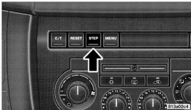
StepButton
UNDERSTANDING YOUR INSTRUMENT PANEL 189
ResetButton
Press the RESET button to reset the display you are in. Press and hold the RESET button (for 2 seconds) to reset all of the displays.

ResetButton
AverageFuelEconomy
Shows the average fuel economy since the last reset. When the fuel economy is reset, the display will read "RESET" or show dashes for two seconds. Then, the history information will be erased, and the averaging will continue from the last fuel average reading before the reset.
DistanceToEmpty
Shows the estimated distance that can be travelled with the fuel remaining in the tank. This is calibrated using the miles per gallon during the last driving period.
TripA
Shows the total distance travelled for trip A since the last reset.
TripB
Shows the total distance travelled for trip B since the last reset.
190UNDERSTANDINGYOURINSTRUMENTPANEL
ElapsedTime
Shows the accumulated ignition ON time since the last reset.
EngineOilPressure
Shows the current engine oil pressure. The scale will read from 0–100 psi (0–689 kPa).
EngineOilTemperature
Shows the current engine oil temperature. The scale will read from 140irc-300ircF ( 60irc-149ircC ).
TirePressureDisplay
Shows the current pressure of all 4 road tires.
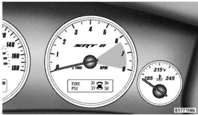
TirePressureDisplay
NOTE: Tires heat up during normal driving conditions. Heat will cause the tire pressure to increase from 2 to 6 psi (14 to 41 kPa) during normal driving conditions. Refer to "Tire Inflation Pressures" in Section 5 for additional information.
MilestoneService
Shows the distance remaining to require service.
NOTE: This display can be reset to the set service interval by pressing and holding the RESET button for 3 seconds.
BlankScreen
Shows a blank screen. Pressing the C/T button returns to the compass/temperature display.
ManualCompassCalibration
If the compass appears erratic and the "CAL" symbol does not appear, you must manually put the compass into the "Calibration" mode.
NOTE: To ensure proper compass calibration, make sure the compass variance is properly set before manually calibrating the compass. Refer to Variance Map.
192UNDERSTANDINGYOURINSTRUMENTPANEL
ToPutIntoaCalibrationMode
Start the engine, and leave the transmission in the P (Park) position. Set the display to "Compass/Temperature." Press and hold the C/T button for approximately 5 seconds to change the display to compass variance mode; holding the button for an additional 5 seconds will flash the "CAL" symbol indicating compass calibration mode. When the "CAL" indicator is flashing, complete one or more 360 degree turns, under 5 mph (8 km/h), in an area free from large metal objects or power lines. The "CAL" indicator will turn off and the compass will function normally.

Compass/TemperatureButton
UNDERSTANDING YOUR INSTRUMENT PANEL 193
CompassVarianceis the difference between magnetic north and geographic north. In some areas of the country, the difference between magnetic and geographic north is great enough to cause the compass to give false readings. If this occurs, the compass variance must be set according to the Compass Variance Map.

194UNDERSTANDINGYOURINSTRUMENTPANEL
To set the variance: Turn the ignition ON and set the display to "Compass/Temperature." Press the C/T button approximately 5 seconds. The last variance zone number will be displayed. Press and hold the STEP button for 1 second to select the new variance zone and press the RESET button to resume normal operation.
RADIOGENERALINFORMATION
RadioBroadcastSignals
Your new radio will provide excellent reception under most operating conditions. Like any system, however, car radios have performance limitations, due to mobile operation and natural phenomena, which might lead you to believe your sound system is malfunctioning. To help you understand and save you concern about these “apparent” malfunctions, you must understand a point or two about the transmission and reception of radio signals.
TwoTypesofSignals
There are two basic types of radio signals... AM or Amplitude Modulation, in which the transmitted sound causes the amplitude, or height, of the radio waves to vary... and FM or Frequency Modulation, in which the frequency of the wave is varied to carry the sound.
ElectricalDisturbances
Radio waves may pick up electrical disturbances during transmission. They mainly affect the wave amplitude, and thus remain a part of the AM reception. They interfere very little with the frequency variations that carry the FM signal.
AMReception
AM sound is based on wave amplitude, so AM reception can be disrupted by such things as lightning, power lines and neon signs.
FMReception
Because FM transmission is based on frequency variations, interference that consists of amplitude variations can be filtered out, leaving the reception relatively clear, which is the major feature of FM radio.
NOTE: The radio, steering wheel radio controls (if equipped), and 6 disc CD/DVD changer (if equipped) will remain active for up to 10 minutes after the ignition switch has been turned off. Opening a vehicle front door will cancel this feature.
SALESCODERAQ-AM/FM/CD(6-DISC)RADIO WITHOPTIONALSATELLITERADIO,HANDS FREEPHONE,ANDVEHICLEENTERTAINMENT SYSTEMS(VES)CAPABILITIES
NOTE: The radio sales code is located on the lower right side of your radio faceplate.
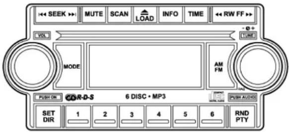
81365bb1
RAQRadio
OperatingInstructions-RadioMode
NOTE: The ignition switch must be in the ON or ACC position to operate the radio.
196UNDERSTANDING YOUR INSTRUMENTPANEL
PowerSwitch/VolumeControl(Rotary)
Press the ON/VOL control to turn the radio ON. Press the ON/VOL a second time to turn OFF the radio.
ElectronicVolumeControl
The electronic volume control turns continuously (360 degrees) in either direction without stopping. Turning the volume control to the right increases the volume and to the left decreases it.
When the audio system is turned on, the sound will be set at the same volume level as last played.
For your convenience, the volume can be turned down, but not up, when the audio system is off and the ignition is ON.
modeButton(RadioMode)
Press the mode button repeatedly to select between the CD player, Satellite Radio, or Vehicle Entertainment System (VES) (if equipped).
SEEKButton(RadioMode)
Press and release the SEEK button to search for the next listenable station in either AM/FM or Satellite (if equipped) mode. Press the right side of the button to seek up and the left side to seek down. The radio will remain tuned to the new station until you make another selection. Holding the button will bypass stations without stopping until you release it.
MUTEButton(RadioMode)
Press the MUTE button to cancel the sound from the speakers. "MUTE" will be displayed. Press the MUTE button a second time and the sound from the speakers will return. Rotating the volume control, turning the radio ON/OFF, or turning OFF the ignition will also return the sound from the speakers
NOTE: In Hands Free Phone (if equipped) mode, the MUTE button mutes the microphone.
SCANButton(RadioMode)
Pressing the SCAN button causes the tuner to search for the next listenable station, in either AM, FM or Satellite (if equipped) frequencies, pausing for 5 seconds at each listenable station before continuing to the next. To stop the search, press SCAN a second time.
MSGorINFOButton(RadioMode)
Press the MSG or INFO button for an RBDS station (one with call letters displayed). The radio will return a Radio Text message broadcast from an FM station (FM mode only).
TimeButton
Press the time button and the time of day will be displayed for 5 seconds.
ClockSettingProcedure
-
Press and hold the time button until the hours blink.
-
Adjust the hours by turning the right side Tune / Audio control.
- After the hours are adjusted, press the right side Tune / Audio control to set the minutes. The minutes will begin to blink.
- Adjust the minutes using the right side Tune / Audio control.
- To exit, press any button/knob or wait 5 seconds.
RW/FF(RadioMode)
Pressing the rewind/fast forward button causes the tuner to search for the next frequency in the direction of the arrows. This feature operates in either AM, FM or Satellite (if equipped) frequencies.
TUNEControl(RadioMode)
Turn the right side rotary control clockwise to increase or counter-clockwise to decrease the frequency.
198UNDERSTANDINGYOURINSTRUMENTPANEL
AM/FMButton(RadioMode)
Press the button to select AM or FM Modes.
SettingtheTone,Balance,andFade
Press the rotary TUNE control and BASS will display. Turn the TUNE control to the right or left to increase or decrease the Bass tones.
Press the rotary TUNE control a second time and MID will display. Turn the TUNE control to the right or left to increase or decrease the Mid Range tones.
Press the rotary TUNE control a third time and TREBLE will display. Turn the TUNE control to the right or left to increase or decrease the Treble tones.
Press the rotary TUNE control a fourth time and BALANCE will display. Turn the TUNE control to the right or left to adjust the sound level from the right or left side speakers.
Press the rotary TUNE control a fifth time and FADE will display. Turn the TUNE control to the left or right to adjust the sound level between the front and rear speakers.
Press the rotary TUNE control again to exit setting tone, balance and fade.
RND/PTYButton(RadioMode)
Pressing this button once will turn on the PTY mode for 5 seconds. If no action is taken during the 5 second time out the PTY icon will turn off. Pressing the PTY button or turning the TUNE rotary knob within 5 seconds will allow the program format type to be selected. Many radio stations do not currently broadcast PTY information.
Toggle the PTY button to select the following format types:
| ProgramType | 16Digit-CharacterDisplay |
| No program type or undefined | None |
| Adult Hits Adult_Hits | |
| Alert Alert Alert Alert | |
| Classical Classical | |
| Classic Rock Classic_Rock | |
| College College | |
| Country Country | |
| Emergency Test Emergency Test | |
| Foreign Language Foreign_Language | |
| Information Information | |
| Jazz Jazz | |
| News News | |
| Nostalgia Nostalgia | |
| Oldies | Oldies |
| Personality | Personality |
| Public | Public |
| Rhythm and Blues | Rhythm_and_Blues |
| Religious Music | Religious_Music |
| Religious Talk | Religious_Talk |
| Rock | Rock |
| Soft | Soft |
| Soft Rock | Soft_Rock |
| Soft Rhythm and Blues | Soft_R_&_B |
| Sports | Sports |
| Talk | Talk |
| Top 40 | Top_40 |
| Weather | Weather |
By pressing the SEEK button when the PTY icon is displayed, the radio will be tuned to the next frequency station with the same selected PTY name. The PTY function only operates when in the FM mode.
If a preset button is activated while in the PTY (Program Type) mode, the PTY mode will be exited and the radio will tune to the preset station.
SET/DIRButton(RadioMode)—ToSetthe Push-ButtonMemory
When you are receiving a station that you wish to commit to push-button memory, press the SET/DIR button. The symbol SET 1 will now show in the display window. Select the button (1-6) you wish to lock onto this station and press and release that button. If a button is not selected within 5 seconds after pressing the SET/DIR button, the station will continue to play but will not be stored into push-button memory.
You may add a second station to each push-button by repeating the above procedure with this exception: Press the SET/DIR button twice and SET 2 will show in the display window. Each button can be set for SET 1 and SET 2 in both AM and FM. This allows a total of 12 AM,12 FM and 12 Satellite (if equipped) stations to be stored into push-button memory. The stations stored in SET 2 memory can be selected by pressing the push-button twice.
Every time a preset button is used a corresponding button number will be displayed.
Buttons 1 - 6 (RadioMode)
These buttons tune the Radio to the stations that you commit to push-button memory {12AM, 12 FM, and 12 Satellite (if equipped) stations}.
OperationInstructions-(CDMODEforCDAudio Play)
NOTE: The ignition switch must be in the ON or ACC position to operate the radio.
NOTE: Note: This Radio is capable of playing compact discs (CD), recordable compact discs (CD-R), rewritable compact discs (CD-RW) compact discs with MP3 tracks and multisession compact discs with CD and MP3 tracks.
InsertingCompactDisc(s)
Gently insert one CD into the CD player with the CD label facing up. The CD will automatically be pulled into the CD Player and the CD icon will illuminate on the radio display.
CAUTION!
ThisCDplayerwillaccept43/4inch(12cm)discs only. Theuseofothersizeddiscsmaydamagethe CDplayermechanism.
You may eject a disc with the radio OFF.
If you insert a disc with the ignition ON and the radio ON, the unit will switch from radio to CD mode and begin to play when you insert the disc. The display will show the disc number, the track number, and index time in minutes and seconds. Play will begin at the start of track 1.
202UNDERSTANDINGYOURINSTRUMENTPANEL
SEEKButton(CDMODEforCDAudioPlay)
Press the right side of the SEEK button for the next selection on the CD. Press the left side of the button to return to the beginning of the current selection, or return to the beginning of the previous selection if the CD is within the first 10 seconds of the current selection.
MUTEButton(CDMODEforCDAudioPlay)
Press the MUTE button to cancel the sound from the speakers. "MUTE" will be displayed. Press the MUTE button a second time and the sound from the speakers will return. Rotating the volume control, turning the radio ON/OFF, or turning OFF the ignition will also return the sound from the speakers.
SCANButton(CDMODEforCDAudioPlay)
Press the Scan button to scan through each track on the CD currently playing.
LOAD/EJECTButton(CDModeforCDAudio Play)
LOAD/EJECT-Load

Press the LOAD/ EJECT button and the push-button with the corresponding number where the CD is being loaded. The radio will display PLEASE WAIT and prompt when to INSERT
DISC. After the radio displays "LOAD DISC" insert the CD into the player.
Radio display will show "LOADING DISC" when the disc is loading, and "READING DISC" when the radio is reading the disc.
LOAD/EJT-Eject

Press the LOAD/ EJT button and the push-button with the corresponding number where the CD was loaded and the disc will unload and move to the entrance for easy removal.
Radio display will show "EJECTING DISC" when the disc is being ejected and prompt the user to remove the disc.
Press and hold the LOAD/ EJT button for 5 seconds and all CDs will be ejected from the radio.
If you have ejected a disc and have not removed it within 15 seconds, it will be reloaded. If the CD is not removed, the radio will continue to play the non-removed CD. If the CD is removed and there are other CD's in the radio, the radio will play the next CD after a 2 minute timeout. If the CD is removed and there are no other CD's in the radio, the radio will remain in CD mode and display "INSERT DISC" for 10 seconds. If no discs are inserted within 10 seconds "NO DISCS LOADED" will be displayed.
On some vehicles a disc can be ejected with the radio and ignition OFF.
TIMEButton(CDMODEforCDAudioPlay)
Press this button to change the display from a large CD playing time display to a small CD playing time display.
RW/FF(CDMODEforCDAudioPlay)
Press and hold FF (Fast Forward) and the CD player will begin to fast forward until FF is released or RW or another CD button is pressed. The RW (Reverse) button works in a similar manner.
TUNEControl(CDMODEforCDAudioPlay)
Pressing the TUNE control allows the setting of the Tone, Fade, and Balance. See Radio Mode.
AM/FMButton(CDMODEforCDAudioPlay)
Switches the Radio to the Radio mode.
204UNDERSTANDINGYOURINSTRUMENTPANEL
RND/PTYButton(RandomPlayButton)(CD MODEforCDAudioPlay)
Press this button while the CD is playing to activate Random Play. This feature plays the selections on the compact disc in random order to provide an interesting change of pace.
Press the SEEK button to move to the next randomly selected track.
Press and hold the FF button to fast forward through the tracks. Release the FF button to stop the fast forward feature.
Press the RND button a second time to stop Random Play.
Buttons 1 - 6 ( C D MODEforCDAudioPlay)
Selects disc positions 1 - 6 for Play/Load/Eject.
NotesOnPlayingMP3Files
The radio can play MP3 files, however, acceptable MP3 file recording media and formats are limited. When writing MP3 files, pay attention to the following restrictions.
SupportedMedia(DiscTypes)
The MP3 file recording media supported by the radio are CD-ROM, CD-R and CD-RW.
SupportedMediumFormats(FileSystems)
The medium formats supported by the radio are ISO 9660 Level 1 and Level 2 and includes the Joliet extension.
When reading discs recorded using formats other than ISO 9660 Level 1 and Level 2, the radio may fail to read files properly and may be unable to play the file normally. UDF and Apple HFS formats are not supported.
The radio uses the following limits for file systems:
• Maximum number of directory levels: 15
• Maximum number of files: 255
• Maximum number of folders: 100
• Maximum number of characters in file/folder names:
- Level 1: 12 (including a separator "." and a 3-character extension)
- Level 2: 31 (including a separator "." and a 3-character extension)
Multisession disc formats are supported by the radio. Multisession discs may contain combinations of normal CD audio tracks and computer files (including MP3 files). Discs created with an option such as "keep disc open after writing" are most likely multisession discs. The use of multisession for CD audio or MP3 playback may result in longer disc loading times.
SupportedMP3FileFormats
The radio will recognize only files with the *.mp3 extension as MP3 files. Non-MP3 files named with the *.mp3 extension may cause playback problems. The radio is designed to recognize the file as an invalid MP3 and will not play the file.
When using the MP3 encoder to compress audio data to an MP3 file, the bit rate and sampling frequencies in the following table are supported. In addition, variable bit rates (VBR) are also supported. The majority of MP3 files use a 44.1 kHz sampling rate and a 192, 160, 128, 96 or VBR bit rates.
| MPEGSpecification | SamplingFrequency(kHz) | Bitrate(kbps) |
| MPEG-1 Audio Layer 3 | 48, 44.1, 32 | 320, 256, 224, 192, 160, 128, 112, 96, 80, 64, 56, 48, 40, 32 |
| MPEG-2 Audio Layer 3 | 24, 22.05, 16 | 160, 128, 144, 112, 96, 80, 64, 56, 48, 40, 32, 24, 16, 8 |
ID3 Tag information for artist, song title and album title are supported for version 1 ID3 tags. ID3 version 2 is not supported by the radios.
Playlist files are not supported. MP3 Pro files are not supported.
PlaybackofMP3Files
When a medium containing MP3 data is loaded, the radio checks all files on the medium. If the medium contains a lot of folders or files, the radio will take more time to start playing the MP3 files.
Loading times for playback of MP3 files may be affected by the following:
• Media - CD-RW media may take longer to load than CD-R media
- Medium formats - Multisession discs may take longer to load than non-multisession discs
- Number of files and folders - Loading times will increase with more files and folders
To increase the speed of disc loading, it is recommended to use CD-R media and single-session discs. To create a single-session disc, enable the Disc at Once option before writing to the disc.
OperationInstructions-(CDModeforMP3Audio Play)
SEEKButton(CDModeforMP3Play)
Pressing the right side of the SEEK button plays the next MP3 File. Pressing the left side of the SEEK button plays the beginning of the MP3 file. Pressing the button within the first ten seconds plays the previous file.
LOAD/EJECTButton(CDModeforMP3Play)
LOAD/EJECT-Load

Press the LOAD/ EJECT button and the push-button with the corresponding number where the CD is being loaded. The radio will display PLEASE WAIT and prompt when to INSERT
DISC. After the radio displays "LOAD DISC" insert the CD into the player.
Radio display will show "LOADING DISC" when the disc is loading.
LOAD/EJECT-Eject

Press the LOAD/ EJECT button and the push-button with the corresponding number where the CD was loaded and the disc will unload and move to the entrance for easy removal.
Radio display will show "EJECTING DISC" when the disc is being ejected and prompt the user to remove the disc.
If you have ejected a disc and have not removed it within 15 seconds, it will be reloaded. If the CD is not removed, the radio will continue to play the non-removed CD. If the CD is removed and there are other CD's in the radio, the radio will play the next CD after a 2 minute timeout. If the CD is removed and there are no other CD's in the radio, the radio will remain in CD mode and display "INSERT DISC" for 2 minutes. After 2 minutes the radio will go to the previous tuner mode.
208UNDERSTANDINGYOURINSTRUMENTPANEL
MSGorINFOButton(CDModeforMP3Play)
Press and MSG or INFO button while playing MP3 disc. The radio scrolls through the following TAG information: Song Title, Artist, File Name, and Folder Name (if available).
Press the MSG or INFO button once more to return to "elapsed time" priority mode.
Press and hold the MSG or INFO button while in the message display priority mode or elapsed time display priority mode will display the song title for each file.
RW/FF(CDModeforMP3Play)
Press the FF side of the button to move forward through the MP3 selection.
TUNEControl(CDModeforMP3Play)
Pressing the TUNE Control allows the adjustment of Tone, Balance, and Fade.
AM/FMButton(CDModeforMP3Play)
Switches back to Radio mode.
RND/PTYButton(CDModeforMP3Play)
Pressing this button plays files randomly.
SET/DIRButton(CDModeforMP3Play)
Press the SET/DIR Button to display folders, when playing an MP3 discs that have a file/folder structure. Turn the TUNE control to display available folders or move through available folders. Press the TUNE control to select a folder.
Buttons 1 - 6 ( C D ModeforMP3Play)
Selects disc positions 1 - 6 for Play/Load/Eject.
OperatingInstructions-HandsFreePhone(If Equipped)
Refer to Hands Free Phone in Section 3 of the Owner's Manual.
OperatingInstructions-SatelliteRadioMode(If Equipped)
Refer to the Satellite Radio section of the Owner's Manual.
OperatingInstructions-VideoEntertainment System(VES®)(IfEquipped)
Refer to separate Video Entertainment System (VES®) Guide.
SALESCODEREC—AM/FM/CD(6-DISC)RADIO WITHNAVIGATIONSYSTEM
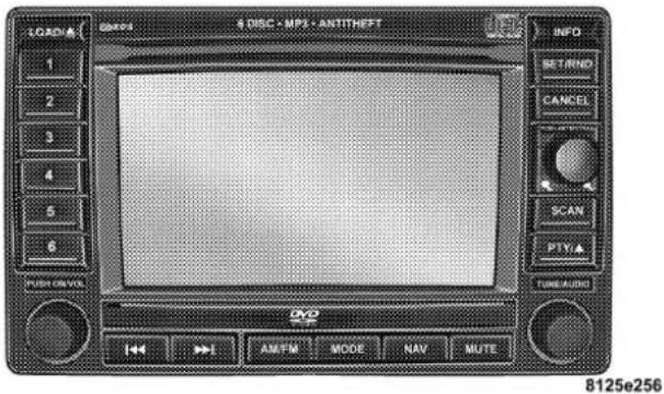
RECRadio
210 UNDERSTANDING YOUR INSTRUMENT PANEL
Satellite Navigation Radio with CD Player with MP3 Capability (REC) - combines a Global-Positioning System-based navigation system with an integrated color screen to provide maps, turn identification, selection menus and instructions for selecting a variety of destinations and routes, AM/FM stereo radio and six-disc CD changer with MP3 capability.
Mapping information for navigation is supplied on a DVD that is loaded into the unit. One map DVD covers all of North America. Refer to your “Navigation User’s Manual” for detailed operating instructions.
OperatingInstructions—SatelliteRadio(If Equipped)
Refer to your "Navigation User's Manual" for detailed operating instructions.
RECSettingtheClock
GPSClock
The GPS receiver used in this system is synchronized to the time data being transmitted by the GPS satellites. The satellites' clock is Greenwich Mean Time (GMT). This is the worldwide standard for time. This makes the system's clock very accurate once the appropriate time zone and daylight savings information is set.
UNDERSTANDING YOUR INSTRUMENT PANEL 211
- At the MainMenuscreen, highlight "Clock Setup" and press ENTER ORpress and hold for 3 seconds the TIME button on the unit's faceplate. The ClockSetup screen appears.

- To show the GPS clock, select "Displayed Clock: GPS Clock" and press ENTER.
- To adjust the time zone, Select "Time Zone" and press ENTER. Select the appropriate time zone and press ENTER.
- To turn daylight savings on or off, select "Daylight Savings" and press ENTER. Select "On" or "Off" and press ENTER.
- Select DONE to exit from the clock setting mode. Press ENTER to save your changes. If you press CANCEL or NAV then your changes will not be saved.
UserDefinedClock
If you wish to set the clock to a time different than the system clock, you can manually adjust the time by choosing the "User Defined Clock" option.
212UNDERSTANDING YOUR INSTRUMENTPANEL
- At the ClockSetupscreen highlight "Displayed Clock: User Defined Clock".
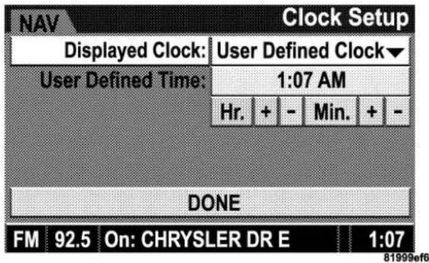
-
To increase the clock by hours, make sure "HR+" is highlighted and press ENTER. Press ENTER again to increase the clock by another hour. You will see on the "User Defined Time" display the number of hours you have increased the clock by.
-
To decrease the clock by one hour, use the Select Encoder to highlight the “-” sign. Press ENTER. Press ENTER again to decrease the clock by another hour.
-
To increase the clock by minutes, make sure "MIN +" is highlighted and press ENTER. Press ENTER again to increase the clock by another minute.
-
To decrease the clock by minutes, use the Select Encoder to highlight the "-" sign. Press ENTER. Press ENTER again to decrease the clock by another minute.
-
Select "DONE" to exit from the clock setting mode. Press ENTER to save your changes. If you press CAN-CEL or NAV then your changes will not be saved.
AudioClockDisplay
Select this option to change the size of the clock on the audio screens.
- When you are at an audio screen, quickly press the TIME button on the navigation faceplate.
- In this example the large clock appears on the screen.

- To switch the clock to the small clock, quickly press TIME again.
- To toggle back to the large clock, simply press TIME.
214UNDERSTANDINGYOURINSTRUMENTPANEL
VIDEOENTERTAINMENTSYSTEM(SALESCODE XRV)—IFEQUIPPED
The optional VESTM (Video Entertainment System) consists of a DVD player and LCD (liquid crystal display) screen, a battery-powered remote control, and two headsets. The DVD player is mounted in the rear of the center console storage bin, and is concealed by a door that lifts up for access. Refer to your VESTM User's Manual for detailed operating instructions.

natural_image
Top-down view of a car dashboard with air vent, control panel, and directional arrow (no text or symbols)DVDPlayerLocation
UNDERSTANDING YOUR INSTRUMENT PANEL 215
The LCD screen is located on the headliner behind the front seats.

natural_image
Interior view of a car dashboard with steering wheel, dashboard screen, and directional arrows indicating movement (no text or symbols)LoweringtheDVDScreen
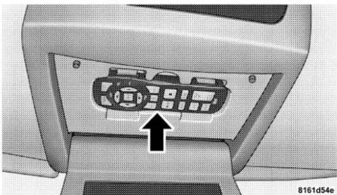
natural_image
Close-up of a computer monitor with a control panel and an arrow pointing to the front panel (no text or symbols visible)Satellite radio uses direct satellite to receiver broadcasting technology to provide clear digital sound, coast to coast. The subscription service provider is Sirius™ Satellite Radio. This service offers over 100 channels of music, sports, news, entertainment, and programming for children, directly from its satellites and broadcasting studios.
SystemActivation
To activate your Sirius Satellite Radio service, call the toll-free number 888-539-7474, or visit the Sirius web site at www.sirius.com. Please have the following information available when activating your system:
- The Electronic Serial Number/Sirius Identification Number (ESN/SID).
- Credit card information.
- Your Vehicle Identification Number.
ElectronicSerialNumber/SiriusIdentification Number(ESN/SID)
The Electronic Serial Number/Sirius Identification Number is needed to activate your Sirius Satellite Radio system. To access the ESN/SID, refer to the following steps:
ESN/SIDAccesswithRECRadios
Refer to the "Navigation User's Manual" for details on satellite radio operation.
ESN/SIDAccesswithRAQRadios
With the ignition switch in the ACCESSORY position and the radio OFF, press the CD Eject and TIME buttons simultaneously for 3 seconds. All twelve ESN/SID numbers will be displayed. The radio will exit the ESN/SID mode when any other button is pushed, the ignition is turned OFF, or 5 minutes has passed since any button was pushed.
SelectingSatelliteModeinRAQRadios
Press the MODE button repeatedly until the word "SIRIUS" appears in the display. These radios will also display the following:
- After 3 seconds, the current channel name and channel number will be displayed for 5 seconds.
- The current program type and channel number will then be displayed for 5 seconds.
- The current channel number will then be displayed until an action occurs.
A CD may remain in the radio while in the Satellite radio mode.
SelectingaChannel
Press and release the SEEK or TUNE buttons to search for the next channel. Press the top of the button to search up and the bottom of the button to search down. Holding the TUNE button causes the radio to bypass channels until the button is released.
Press and release the SCAN button (if equipped) to automatically change channels every 7 seconds. The radio will pause on each channel for 7 seconds before moving on to the next channel. The word "SCAN" will appear in the display between each channel change. Press the SCAN button a second time to stop the search.
NOTE: Channels that may contain objectionable content can be blocked. Contact Sirius Customer Care at 888-539-7474 to discuss options for channel blocking or unblocking. Please have your ESN/SID information available.
218 UNDERSTANDING YOUR INSTRUMENT PANEL
StoringandSelectingPre-SetChannels
In addition to the 10 AM and 10 FM pre-set stations, you may also commit 10 satellite stations to push button memory. These satellite channel pre-set stations will not erase any AM or FM pre-set memory stations. Follow the memory pre-set procedures that apply to your radio.
UsingthePTY(ProgramType)Button—If Equipped
Follow the PTY button instructions that apply to your radio.
PTYButton"SCAN"
When the desired program type is obtained, press the "SCAN" button within five seconds. The radio will play 7 seconds of the selected channel before moving to the next channel of the selected program type. Press the "SCAN" button a second time to stop the search.
NOTE: Pressing the "SEEK" or "SCAN" button while performing a music type scan will change the channel by one and stop the search. Pressing a pre-set memory button during a music type scan, will call up the memory channel and stop the search.
PTYButton"SEEK"
When the desired program is obtained, press the "SEEK" button within five seconds. The channel will change to the next channel that matches the program type selected.
SatelliteAntenna
To ensure optimum reception on vehicles available with a luggage rack, do not place items on the roof around the rooftop antenna location. Metal objects placed within the line of sight of the antenna will cause decreased performance. Larger luggage items should be placed as far forward as possible. Do not place items directly on or above the antenna.
ReceptionQuality
Satellite reception may be interrupted due to one of the following reasons.
- The vehicle is parked in an underground parking structure or under a physical obstacle.
- Dense tree coverage may interrupt reception.
- Driving under wide bridges or along tall buildings can cause intermittent reception.
- Placing objects over or too close to the antenna can cause signal blockage.
REMOTESOUNDSYSTEMCONTROLS
The remote sound system controls are located on the rear surface of the steering wheel. Reach behind the wheel to access the switches.

The right hand control is a rocker type switch with a push-button in the center and controls the volume and mode of the sound system. Pressing the top of the rocker switch will increase the volume and pressing the bottom of the rocker switch will decrease the volume.
220UNDERSTANDINGYOURINSTRUMENTPANEL
Pressing the center button will make the radio switch between the various modes available (AM/FM/TAPE/CD, Etc.).
The left hand control is a rocker type switch with a push-button in the center. The function of the left hand control is different depending on which mode you are in.
The following describes the left hand control operation in each mode.
RadioOperation
Pressing the top of the switch will "Seek" up for the next listenable station and pressing the bottom of the switch will "Seek" down for the next listenable station.
The button located in the center of the left hand control will tune to the next preset station that you have programmed in the radio preset push-button.
CDPlayer
Pressing the top of the switch once will go to the next track on the CD. Pressing the bottom of the switch once will go to the beginning of the current track or to the beginning of the previous track if it is within one second after the current track begins to play.
If you press the switch up or down twice it plays the second track, three times, it will play the third, etc.
The center button on the left side rocker switch has no function for a single disc CD player. However, when a multiple disc CD player is equipped on the vehicle, the center button will select the next available CD in the player.
CD/DVDDISCMAINTENANCE
To keep the CD/DVD discs in good condition, take the following precautions:
- Handle the disc by its edge; avoid touching the surface.
- If the disc is stained, clean the surface with a soft cloth, wiping from center to edge.
- Do not apply paper, paper CD labels, or tape to the disc; avoid scratching the disc.
- Do not use solvents such as benzine, thinner, cleaners, or antistatic sprays.
- Store the disc in its case after playing.
- Do not expose the disc to direct sunlight.
- Do not store the disc where temperatures may become too high.
RADIOOPERATIONANDCELLULARPHONES
Under certain conditions, the cellular phone being On in your vehicle can cause erratic or noisy performance from your radio. This condition may be lessened or eliminated by relocating the cellular phone antenna. This condition is not harmful to the radio. If your radio performance does not satisfactorily “clear” by the repositioning of the antenna, it is recommended that the radio volume be turned down or off during cellular phone operation.
CLIMATECONTROLS
AutomaticTemperatureControl
The Infrared Dual-Zone Climate Control System automatically maintains the interior comfort level desired by the driver and passenger. This is accomplished by a dual sun-sensor in the top of the instrument panel, and an infrared sensor located in the face of the control unit. There are also various sensors monitored by this system which take account for vehicle speed, A/C pressure, outside temperature, and engine cooling temperature. The infrared sensor independently measures the surface temperature of the driver and passenger. Based on the sensor input, the system automatically adjusts the air flow temperature, the air flow volume, and amount of outside air recirculation. This maintains a comfortable temperature even under changing conditions.

natural_image
Front view of an automotive air conditioning control panel with dials and gauges (no readable text or symbols)AutomaticTemperatureControls
NOTE: The numbers on the temperature dial represent a comfort setting when the Mode knob is set to Auto, and not the actual air temperature.
Operation of the system is quite simple. Begin by turning the right mode knob to AUTO, and place the blower control (left knob) to either LO AUTO or HI AUTO. The
LO AUTO position should be used for front seat occupants only. The HI AUTO position should be used when more air flow is desired, or when rear seat occupants are present. Dial in the comfort setting you would like the system to maintain by rotating the driver's or passenger's control knob. Once the comfort level is selected the system will maintain that level automatically using the heating system. Should the desired comfort level require air conditioning, the system will automatically make the adjustment.
You will experience the greatest efficiency by simply allowing the system to function automatically. Selecting the OFF position on the fan control stops the system completely.
NOTE: The temperature setting can be adjusted at any time without affecting automatic control operation. However, if the driver and/or passenger temperature knobs are set to the full hot or full cold positions, the air
temperature out of the ducts will be full hot or full cold respectively. With the temperature setting in these positions, the system does not attempt automatic comfort control.

The air conditioning in this system is automatic. Pressing this button while in AUTO mode will cause the LED to flash three times and remain off.
This indicates that the system is in AUTO and requesting the air conditioning is not necessary.

The system will automatically control recirculation. However, pressing this button will temporarily put the system in recirculation mode.
This can be used when outside conditions such as smoke, odors, dust, or high humidity are present. This will cause the LED to illuminate.
NOTE:
- The surface of the climate control panel, and the top center of the instrument panel should be kept free of
224UNDERSTANDINGYOURINSTRUMENTPANEL
debris due to the climate control sensor's location. Mud on the windshield may also cause poor operation of this system.
- To provide you with maximum comfort in the automatic mode, during cold start-ups the blower fan will remain off until the engine warms up. However, the fan will engage immediately if the defrost mode is selected or if you manually select a blower speed.
- Under certain conditions (after the vehicle is turned off) the climate control system may recalibrate and a noise may be heard for 20 seconds. This is part of normal operation.
- Most of the time, when in Automatic operation, you can temporarily put the system into recirculation mode by pressing the Recirc button. However, under certain conditions in automatic the system is blowing air out of the defrost vents. When these conditions are
present and the Recirc button is pressed the indicator will flash and remain off. This tells you that you are unable to go into recirculation mode at this time. If you would like to go to Recirculation mode, you must first move your mode knob to panel, panel/floor or floor, then hit the Recirc button. This feature will reduce the possibility of window fogging.
ManualOperation
This system offers a full complement of manual override features which consist of Blower Preferred Automatic, Mode Preferred Automatic with Manual Air Temperature Control and Manual. This means the customer can override the blower, mode and disable automatic temperature control completely.
NOTE: Please read the Automatic Temperature Control Operation Chart below for details.
| Automatic Temperature Control Operation | The System will... | |||||
| Operation | How | Blower Control | Mode Control | Air Temperature Control | Air Recirculation Control | A/C Operation |
| Full Automatic Operation | Set blower knob to either Hi or Lo Auto. Set temperature knobs for Comfort. | Automatic | Automatic | Automatic | Automatic but can be overridden. | Automatic |
| Blower Preferred Automatic | Set blower knob to any desired airflow level other than Hi or Lo Auto. Set temperature knobs for Comfort. | User selectable to any speed. | Automatic | Automatic | Automatic but can be overridden. | Automatic |
| Mode Preferred and Manual Air Temperature Control | Set mode knob to any desired air delivery point. Adjust Temperature knobs to select the desired temperature. | Automatic. Although Auto Lo or Hi can be selected, a manually selected airflow level is recommend for the optimum comfort. | Manual | *Manual-automatic control of air temperature is disabled. User must adjust temperature knobs to obtain the desired temperature. | User selectable outside or recirculated. | User selectable A/C on or off. |
| Full Manual Operation | Set blower knob to any desired airflow level other than Hi or Lo Auto. Set mode knob to any desired air delivery point other than Auto. Adjust Temperature knobs to select the desired temperature. | Manual | Manual | *Manual-automatic control of air temperature is disabled. User must adjust temperature knobs to obtain the desired temperature. | User selectable outside or recirculated. | User selectable A/C on or off. |
*Manual Air Temperature Control Operation:
When the Mode knob is set to any position other than Auto, the Temperature knob operates in the non automatic comfort condition. The numbers on the Temperature dial are no longer valid in this mode. This mode allows the user to select any desired air temperature. When the temperature knob is in full counterclockwise position, the air temperature will be Cooler. As the knob is rotated clockwise, the temperature will increase gradually until the knob reaches the full clockwise position.
817dd45b
NOTE: Regardless of the type of operation, when a temperature knob is set to the full clockwise or full counterclockwise position, the system will deliver full hot or full cold air out of the ducts, respectively.
The operator can override the AUTO mode setting and select the direction of the air by rotating the right mode knob to one of the following positions. When the Mode is set to any position other than AUTO, the automatic control of air temperature is disabled. The user must adjust the temperature knobs to obtain the desired temperature.
- Defrost

Air is directed to the windshield through the outlets at the base of the windshield. Air is also tied to the front door windows through the side of demister grilles. Some airflow is delivered to poor while in defrost so that comfort can be attained.
NOTE: The defrost mode is not automatically selected. It must be manually selected, when desired.
- Defrost/Floor

Air flows through the front and rear floor outlets and the outlets at the base of the windshield. Air is also directed to the front door windows through the side window demister grilles. Some air-is delivered to the floor while in defrost so that port can be maintained.
- Floor

Air flows through the floor outlets located under the instrument panel and into the rear seating through vents under the front seats. Some airflow delivered to defrost while in floor mode, so that port can be maintained.
- Bi-Level

Air flows both through the outlets located in the instrument panel and those located on the floor.
Air flows through the registers in the back of the center console, and under the front seats to the rear seat passengers. These registers can be closed to block airflow. The center console outlets deliver conditioned air while the floor outlets deliver heated air.
- Panel

Air flows through the outlets located in the instrument panel. Air flows through the registers in back of the center console to the rear seat passen-s. These registers can be closed to block airflow.

Depress this button to turn on and off the air conditioning during manual operation only. Conditioned outside air is then directed through the outlets selected on the mode control dial. The button includes an LED that illuminates when manual operation is selected.
NOTE: To manually control the air conditioning the mode selector must be moved out of the AUTO position.
UNDERSTANDING YOUR INSTRUMENT PANEL

This button can be used to block out smoke, odors, dust, high humidity, or if rapid cooling is desired. The recirculation mode should only be used temporarily. The button includes an LED that illuminates, which indicates that the recirculation mode is active. You may use this feature separately.
NOTE: Extended use of recirculation may cause the windows to fog. If the interior of the windows begins to fog, press the "Recirculate" icon button to return to outside air. Some temp./humidity conditions will cause captured interior air to condense on windows and hamper visibility. For this reason, the system will not allow "Recirculate" to be selected while in the defrost or defrost/floor modes. Attempting to use the recirculation while in these modes will cause the LED in the button to blink and then turn off.
228UNDERSTANDINGYOURINSTRUMENTPANEL
OperatingTips
WindowFogging
Windows will fog on the inside when the humidity inside the vehicle is high. This often occurs in mild or cool temperatures when it's rainy or humid. In most cases turning on the Air-conditioning (pressing the snowflake button) will clear the fog. Adjust the temperature control, air direction and blower speed to maintain comfort.
As the temperature gets colder it may be necessary to direct air onto the windshield. Adjust the temperature control and blower speed to maintain comfort. Higher blower speeds will reduce fogging. Interior fogging on the windshield can be quickly removed by selecting the defrost mode.
Regular cleaning of the inside of the windows with a non-filming cleaning solution (vinegar and water works very well) will help prevent contaminates (cigarette
smoke, perfumes, etc.) from sticking to the windows. Contaminates increase the rate of window fogging.
SummerOperation
Air conditioned vehicles must be protected with a high quality antifreeze coolant during summer to provide proper corrosion protection and to raise the boiling point of the coolant for protection against overheating. A 50 % concentration is recommended. Refer to Recommended Fluids and Genuine Parts for the proper coolant type.
When using the air conditioner in extremely heavy traffic in hot weather especially when towing a trailer, additional engine cooling may be required. If this situation is encountered, operate the transmission in a lower gear to increase engine RPM, coolant flow and fan speed. When stopped in heavy traffic, it may be necessary to shift into N (Neutral) and depress the accelerator slightly for fast idle operation to increase coolant flow and fan speed.
Your air conditioning system is also equipped with an automatic recirculation system. When the system senses a heavy load or high heat conditions, it may use partial Recirculation A/C mode to provide additional comfort.
WinterOperation
When operating the system during the winter months, make sure the air intake, located directly in front of the windshield, is free of ice, slush, snow, or other obstructions.
VacationStorage
Anytime you store your vehicle, or keep it out of service (i.e. vacation) for two weeks or more, run the air conditioning system at idle for about five minutes in the fresh air and high blower setting. This will insure adequate system lubrication to minimize the possibility of compressor damage when the system is started again.
■Automatic Transmission....238
□Brake/Transmission Interlock System ..... 2 3 8
□5-Speed Automatic Transmission .....239
□Gear Ranges 239
□ Rocking The Vehicle .....241
■AutoStick....241
□AutoStick Operation....242
□ AutoStick General Information .....243
■Parking Brake....244
■Anti-Lock Brake System....245
■Power Steering....248
■ Tire Safety Information .....250
□Tire Markings 250
□Run Flat Tires....258
□Tire Pressure 258
□Tire Inflation Pressures....260
□Tire Pressures For High Speed Operation . . . . 2 6 1
□Radial-Ply Tires....262
□Tire Spinning 263
□Tread Wear Indicators 263
□Life Of Tire....264
□Replacement Tires....265
□Alignment And Balance....266
■Tire Rotation Recommendations....266
■Tire Pressure Monitor System (TPMS) ..... 2 6 6
□Premium System....266
□General Information....270
■ Fuel Requirements .....270
□Reformulated Gasoline....271
□ Gasoline/Oxygenate Blends .....271
□MMT In Gasoline 272
□ Materials Added To Fuel .....272
□Fuel System Cautions....273
□Carbon Monoxide Warnings....273
■Adding Fuel....274
□Fuel Filler Cap (Gas Cap)....274
■Trailer Towing....277
□Common Towing Definitions....277
□Trailer Hitch Classification....281
□Trailer Towing Weights (Maximum Trailer Weight Ratings) ..... 2 8 2
□Trailer And Tongue Weight....282
□Towing Requirements....284
□Towing Tips....288
■Recreational Towing (Behind Motorhome, Etc.) .. 289
Before starting your vehicle, adjust your seat, adjust both inside and outside mirrors, and fasten your seat belts.
CAUTION!
Longperiodsofengineidling,especiallyathigh enginespeedscancauseexcessiveexhausttemperatureswhichcandamageyourvehicle.Donotleave yourvehicleunattendedwiththeengineerunning.
WARNING!
Donotleavechildrenoranimalsinsideparked vehiclesinhotweather.Interiorheatbuildupmay causeseriousinjuryordeath.
Start the engine with the gear selector in the N (Neutral) or P (Park) position. Apply the brakes before shifting to any driving gear.
NormalStarting
Do not press the accelerator. Turn the ignition key briefly to START position, and release it. The starter motor will continue to run, but will automatically disengage itself when the engine is running.
NOTE: The starter motor may run up to 30 seconds in very cold conditions until the engine is started. The starter can be disengaged by turning the ignition key to the OFF position, if required.

IgnitionKeyPositions
ExtremeColdWeather(below-20°F(-29°C)
To insure reliable starting at these temperatures, use of an externally powered electric engine block heater (available from your authorized dealer) is recommended.
IfEngineFailstoStart
If the engine fails to start after you have followed the "Normal Starting" or "Extreme Cold Weather" procedures, it may be flooded. Push the accelerator pedal all the way to the floor and hold it there while cranking the engine. This should clear any excess fuel in case the engine is flooded.
CAUTION!
Topreventdamagetothestarter, donotcrank the engineformorethan15secondsatatime. Wait10to 15secondsbeforetryingagain.
WARNING!
Neverpourfuelorotherflammableliquidsintothe throttlebodyairinletopeninginanattempttostart thevehicle. Thiscouldresultinaflashfirecausing seriouspersonalinjury.
WARNING!
Donotattempttopushortowyourvehicletogetit started. Vehiclesequippedwithanautomatictransmissioncannotbestedthisway.Unburnedfuel couldenterthecatalyticconverterandoncethe enginehasstarted,igniteanddamagetheconverter andvehicle.Ifthevehiclehasadischargedbattery, boostercablesmaybeusedtoobtainastartfroma boosterbatteryorthebatteryinanothervehicle.This typeofstartcanbedangerousifdoneimproperly. RefertoSection6ofthismanualforproperjump startingproceduresandfollowthemcarefully.
If the engine has been flooded, it may start to run, but not have enough power to continue running when the key is
released. If this occurs, continue cranking with the accelerator pedal pushed all the way to the floor. Release the accelerator pedal and the key once the engine is running smoothly.
If the engine shows no sign of starting after two 15-second periods of cranking with the accelerator pedal held to the floor, the "Normal Starting" or "Extreme Cold Weather" procedures should be repeated.
AfterStarting
The idle speed will automatically decrease as the engine warms up.
CAUTION!
Longperiodsofengineidling,especiallyathigh enginespeedscancauseexcessiveexhausttemperatureswhichcandamageyourvehicle.Donotleave yourvehicleunattendedwiththeengine running.
WARNING!
Donotleavechildrenoranimalsinsideparked vehiclesinhotweather.Interiorheatbuildupmay causeseriousinjuryordeath.
AUTOMATICTRANSMISSION
CAUTION!
Damagethetransmissionmayoccurifthefollowingprecautionsarenotobserved:
- ShiftintoP(Park)onlyafterthevehiclehascome toacompletestop.
- ShiftintooroutofR(Reverse)onlyafterthe vehiclehascometoacompletestopandthe engineisatidlespeed.
- DonotshiftfromR(Reverse),P(Park),orN(Neutral)intoanyforwardgearwhentheengine isaboveidlespeed.
- Beforeshiftingintoanygear,makesureyourfoot isfirmlyonthebrakepedal.
WARNING!
ItisdangeroustoshifttheselectorleveroutofP (Park)orN(Neutral)iftheenginespeedishigher thanidlespeed.Ifyourfootisnotfirmlyonthe brakepedal,thevehiclecouldacceleratequickly forwardorinreverse.Youcouldlosecontrolofthe vehicleandhitsomeoneorsomething.Onlyshift intogearwhentheengineisidlingnormallyand whenyourfootisfirmlyonthebrakepedal.
Brake/TransmissionInterlockSystem
This system prevents you from moving the gear shift out of P (Park) and into any gear unless the brake pedal is pressed. This system is active only while the ignition switch is in the ON position. Always depress the brake pedalfirst, before moving the gear selector out of P (Park).
5-SpeedAutomaticTransmission
The electronically controlled transmission provides a precise shift schedule. The transmission electronics are self-calibrating; therefore, the first few shifts on a new vehicle, may be somewhat abrupt. This is a normal condition, and precision shifts will develop within a few hundred miles.

natural_image
Interior view of a car gear shift lever system (no text or symbols visible)AutomaticShiftControls
WARNING!
ItisdangeroustoshifttheselectorleveroutofP (Park)orN(Neutral)iftheenginespeedishigher thanidlespeed.Ifyourfootisnotfirmlyonthe brakepedal,thevehiclecouldacceleratequickly forwardorinreverse.Youcouldlosecontrolofthe vehicleandhitsomeoneorsomething.Onlyshift intogearwhentheengineisidlingnormallyand whenyourfootisfirmlyonthebrakepedal.
GearRanges
NOTE: After selecting any gear range, wait a moment to allow the selected gear to engage before accelerating. This is especially important when the engine is cold. If there is a need to restart the engine be sure to cycle the key to the LOCK position before restarting. Transmission gear engagement may be delayed after restarting the engine if the key is not cycled to the LOCK position first.
Supplements the parking brake by locking the transmission. The engine can be started in this range. Never use P (Park) while the vehicle is in motion. Apply the parking brake when leaving the vehicle in this range.
WARNING!
Unintendedmovementofvehiclecouldinjure thoseinandnearthevehicle.Aswithallvehicles, youshouldneverexitavehiclewhiletheengineis running.Beforeexitingavehicle,youshouldapply theparkbrake,shiftthetransmissionintoP(Park), andremovethekeyfromtheignition.Oncethekey isremovedfromtheignitionthetransmissionshift leverislockedintheP(Park)position,securingthe vehicleagainstunwantedmovement.Furthermore, youshouldneverleavechildrenunattendedinsidea vehicle.
R(Reverse)
Shift into this range only after the vehicle has come to a complete stop.
N(Neutral)
No power is transmitted from the engine to the drive axle. When the brakes are released, the vehicle can roll freely. Do not engage in N (Neutral) position while driving except to coast when the vehicle is in danger of skidding (e.g., on icy roads).
D(Drive)
The transmission automatically upshifts through fifth gear. The D (Drive) position provides optimum driving characteristics under all normal operating conditions. For additional shifting information, refer to “Autostick” later in this section.
RockingtheVehicle
If the vehicle becomes stuck in snow, sand, or mud, it can often be moved by a rocking motion. Move the gear selector rhythmically between D (Drive) and R (Reverse), while applying slight pressure to the accelerator.
NOTE: The Electronic Stability Program (ESP) and Traction Control (if equipped) should be turned OFF before attempting to rock the vehicle. Refer to “Electronic Brake Control System” in Section 3 of this manual.
The least amount of accelerator pedal pressure to maintain the rocking motion without spinning the wheels or racing the engine is most effective. Racing the engine or spinning the wheels, due to the frustration of not freeing the vehicle, may lead to transmission overheating and failure. Allow the engine to idle with the transmission selector in N (Neutral) for at least one minute after every five rocking-motion cycles. This will minimize overheating and reduce the risk of transmission failure during prolonged efforts to free a stuck vehicle.
CAUTION!
When "rocking" astuck vehiclebymoving between "First" and R (Reverse), donotspinthewheels faster than 15 mph (24 km/h), or drivetrain damagemay result.
AUTOSTICK
Autostick is a driver-interactive transmission that offers manual gear shifting capability to provide the driver with more control. Autostick allows the driver to increase engine braking ability, control upshift and downshift points, and enhance the driving experience. This system
can also provide the driver with more control during passing, city driving, mountain driving, trailer towing, and many other situations.
AutostickOperation
By placing the shift lever in the D (Drive) position the lever can be moved from side to side. This allows the driver to engage the AutoStick mode. Moving the shift lever to the right (+) or the left (-) will engage the Autostick mode. In normal driving mode (Boxed "D" displayed in the PRNDL), moving the shift lever to the right (+) will engage the Autostick mode putting the transmission in the currently engaged gear. Moving the shift lever to the Left (-) will engage the Autostick mode and downshift the transmission 1 gear. For example, the transmission is in Normal Mode and is currently operating in 3rd gear, a boxed D is displayed in the PRNDL, a push to the right will engage the Autostick mode in 3rd and a Boxed 3 will be displayed in the PRNDL. A push to the left (-) will engage Autostick mode and downshift to 2nd gear and a Boxed 2 will be displayed in the PRNDL. Once Autostick mode is engaged a move to the Right (+) or left (-) will trigger a upshift (+) or trigger a downshift (-).
NOTE: In the Autostick mode, the transmission will only shift up and down when Left or Right (D-/D+) is manually selected by the driver.
The transmission will not allow a downshift if the downshift would result in a engine overspeed condition. The transmission will always allow a upshift from 1st to 2nd gear, however 2nd - 3rd, 3rd - 4th, and 4th - 5th upshifts will not be allowed if the vehicle speed is to low to maintain operation in the selected gear. The transmission will automatically downshift as the vehicle slows to a stop.
When in the Autostick mode, as the engine RPM nears the engine maximum speed, an "UPSHIFT" message will appear in the Electronic Vehicle Information Center
(EVIC) portion of your instrument cluster. This message appears in order to alert the driver that the engine speed is approaching it's maximum value and a upshift to the next gear is required. In the event that the driver does not upshift, the engine control system will limit the engine speed to protect the engine. Refer to "Electronic Vehicle Information Center" in Section 4 of this manual.
Shifting into or out of the Autostick mode can be done at any time without taking your foot off the accelerator pedal. When the driver wishes to engage Autostick, simply move the shift lever to the Left or Right (D-/D+) position while in D (Drive).
Hold the shift lever to the right for at least one second to disengage Autostick. The transmission will now operate automatically; shifting between the five available gears.
AutostickGeneralInformation
- You can start out in first or second gear. The system will ignore attempts to upshift at too low of a vehicle speed.
- The transmission will automatically downshift to first gear when coming to a stop.
- Starting out in second gear is helpful in snowy or icy conditions.
- Avoid using speed control when Autostick is engaged.
- The transmission will not automatically shift up when maximum engine speed is reached while Autostick is engaged.
- Transmission shifting will be more noticeable when Autostick is engaged.
To set the parking brake, pull the lever up as firmly as possible. When the parking brake is applied with the ignition ON, the "Brake Warning Light" in the instrument cluster will light. To release the parking brake, pull up slightly, press the center button, then lower the lever completely.
NOTE: The instrument cluster "Brake Warning Light" indicates only that the parking brake is applied. It does not indicate the degree of brake application.

natural_image
Close-up of a car interior showing hoses and a valve assembly (no visible text or symbols)ParkingBrake
Be sure the parking brake is firmly set when parked and the gear shift lever is in the P (Park) position. When parking on a hill, you should apply the parking brake before placing the gear shift lever in P (Park), otherwise the load on the transmission locking mechanism may make it difficult to move the selector out of P (Park).
WARNING!
- Alwaysfullyapplytheparkingbrakewhenleavingyourvehicle,oritmayrollandcausedamage orinjury. Also,becertaintoleavethetransmissioninP(Park).Failuretodosomayallowthe vehicletorollandcausedamageorinjury.
- Leavingchildreninavehicleunattendedisdangerousforanumberofreasons.Achildorothers couldbeinjured.Childrenshouldbewarnednot totouchtheparkingbrakeorthegaselector lever.Don'tleavethekeysintheignition.Achild couldoperatepowerwindows,othercontrols,or movethevehicle.
- Besuretheparkingbrakeisfullydisengaged beforedriving,failuretodosocanleadtobrake problemsduetoexcessiveheatingoftherear brakes.
When parking on a hill, turn the front wheels toward the curb on a downhill grade and away from the curb on an uphill grade.
The parking brake should always be applied whenever the driver is not in the vehicle.
ANTI-LOCKBRAKESYSTEM
The Anti-Lock Brake System (ABS) is designed to aid the driver in maintaining vehicle control under adverse braking conditions. The system operates with a separate computer to modulate hydraulic pressure to prevent wheel lock-up and help avoid skidding on slippery surfaces.
All vehicle wheels and tires must be the same size and type and tires must be properly inflated to produce accurate signals for the computer.
WARNING!
Significant overor underinflation of tirescan lead to loss of braking effectiveness.
The Anti-Lock Brake System conducts a low-speed self-test at about 12 mph (20 km/h). If you have your foot lightly on the brake while this test is occurring you may feel slight pedal movement. The movement can be more apparent on ice and snow. This is normal.
The Anti-Lock Brake System pump motor runs during the self-test at 12 mph (20 km/h) and during an ABS stop. The pump motor makes a low humming noise during operation, which is normal.
WARNING!
PumpingoftheAnti-LockBrakeswilldiminish theireffectivenessandmayleadtoanaccident. Pumpingmakethestoppingdistancelonger.Just pressfirmlyonyourbrakepedalwhenyouneedto slowdownorstop.
WARNING!
- The Anti-Lock Brake System (ABS) cannot prevent then natural law so of physics from acting on the vehicle, nor can it increase braking or steering efficiency beyond that afforded by the condition of the vehicle brakes and tires or the extraction afforded.
- TheABScannotpreventaccidents,including thoseresultingfromexcessivespeedinturns, followinganothervehicletooclosely,orhydroplaning.Onlyasafe,attentive,andskillfuldriver canpreventaccidents.
- The capabilities of an AB equipped vehicle must never be exploited in areckless or dangerous manner which could jeopardize the user's safety or the safety of others.
CAUTION!
The Anti-Lock Brake System missubjecttopossible detrimentaleffectsofelectronicinterferencecaused byimproperlyinstalledafter-marketradiosortelephones.
NOTE: During severe braking conditions, a pulsing sensation may occur and a clicking noise will be heard. This is normal, indicating that the Anti-Lock Brake System is functioning.
WARNING!
Touseyourbrakesandacceleratormoresafely, followthesetips:
- Do not "ride" the brakes by resting your foot on the pedal. This could overheat the brakes and result in unpredictable braking action, longer stopping distances, or brake damage.
- When descending mountains or hills, repeated braking can cause brake fade with loss of braking control. Avoid repeated heavy braking by downshifting the transmission or locking out overdrive whenever possible.
- Engines may idle at higher speeds during warm-up, which could cause rear wheels to spin and result in loss of vehicle control. Be especially careful while driving on slippery roads, in close-quarter maneuvering, parking or stopping.
- Do not drive too fast for road conditions, especially when roads are wet or slushy. A wedge of water can
build up between the tire tread and the road. This hydroplaning action can cause loss of traction, braking ability, and control.
- After going through deep water or a car wash, brakes may become wet, resulting in decreased performance and unpredictable braking action. Dry the brakes by gentle, intermittent pedal action while driving at very slow speeds.
POWERSTEERING
The standard power steering system will give you good vehicle response and increased ease of maneuverability in tight spaces. The system will provide mechanical steering capability if power assist is lost.
If for some reason the power assist is interrupted, it will still be possible to steer your vehicle. Under these conditions, you will observe a substantial increase in steering effort, especially at very low vehicle speeds and during parking maneuvers.
NOTE: Increased noise levels at the end of the steering wheel travel are considered normal and do not indicate that there is a problem with the power steering system.
Upon initial start-up in cold weather, the power steering pump may make noise for a short amount of time. This is due to the cold, thick fluid in the steering system. This noise should be considered normal, and does not in any way damage the steering system.
WARNING!
Continuedoperationwithreducedpowersteering assistcouldposeasafetyrisktoyourselfandothers. Serviceshouldbeobtainedassoonaspossible.
CAUTION!
Prolongedoperationofthesteeringsystematthe endofthesteeringwheeltravelwillincreasethe steeringfluidtemperatureanditshouldbeavoided whenpossible.Damagetothepowersteeringpump mayoccur.
TIRESAFETYINFORMATION
TireMarkings
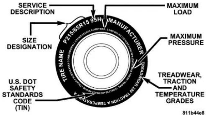
NOTE:
- P (Passenger)-Metric tire sizing is based on U.S. design standards. P-Metric tires have the letter "P" molded into the sidewall preceding the size designation. Example: P215/65R15 95H.
- European Metric tire sizing is based on European design standards. Tires designed to this standard have the tire size molded into the sidewall beginning with the section width. The letter "P" is absent from this tire size designation. Example: 215/65R15 96H
- LT (Light Truck)-Metric tire sizing is based on U.S. design standards. The size designation for LT-Metric tires is the same as for P-Metric tires except for the letters "LT" that are molded into the sidewall preceding the size designation. Example: LT235/85R16.
- Temporary Spare tires are high-pressure compact spares designed for temporary emergency use only. Tires designed to this standard have the letter "T" molded into the sidewall preceding the size designation. Example: T145/80D18 103M.
- High Flotation tire sizing is based on U.S. design standards and it begins with the tire diameter molded into the sidewall. Example: 31x10.5 R15 LT.
TireSizingChart
| EXAMPLE: |
| SizeDesignation: P= Passenger car tire size based on U.S. design standards“...blank...” = Passenger car tire based on European design standards LT= Light Truck tire based on U.S. design standards T= Temporary Spare tire 31= Overall Diameter in Inches (in) |
| 215= Section Width in Millimeters (mm) |
| 65= Aspect Ratio in Percent (%)—Ratio of section height to section width of tire. 10.5= Section Width in Inches (in) |
| R= Construction Code—“R”means Radial Construction.—“D”means Diagonal or Bias Construction. |
| 15= Rim Diameter in Inches (in) |
| EXAMPLE: |
| ServiceDescription: |
| 95= Load Index—A numerical code associated with the maximum load a tire can carry. |
| H= Speed Symbol—A symbol indicating the range of speeds at which a tire can carry a load corresponding to its load index under certain operating conditions.—The maximum speed corresponding to the Speed Symbol should only be achieved under specified operating conditions. (i.e. tire pressure, vehicle loading, road conditions, and posted speed limits). |
| LoadIdentification: |
| "....blank..." = Absence of any text on sidewall of the tire indicates a Standard Load (SL) Tire |
| ExtraLoad(XL)= Extra Load (or Reinforced) Tire |
| LightLoad= Light Load Tire |
| C,D,E= Load range associated with the maximum load a tire can carry at a specified pressure |
| MaximumLoad— Maximum Load indicates the maximum load this tire is designed to carry. |
| Maximum Pressure — Maximum Pressure indicates the maximum permissible cold tire inflation pressure for this tire. |
TireldentificationNumber(TIN)
The TIN may be found on one or both sides of the tire; however, the date code may only be on one side. Tires with white sidewalls will have the full TIN including date code located on the white sidewall side of the tire.
Look for the TIN on the outboard side of black sidewall tires as mounted on the vehicle. If the TIN is not found on the outboard side then you will find it on the inboard side of the tire.
| EXAMPLE: |
| DOTMAL9ABCD0301 |
| DOT = Department of Transportation—This symbol certifies that the tire is in compliance with the U.S. Department of Transportation tire safety standards, and is approved for highway use. |
| MA = Code representing the tire manufacturing location. (2 digits) |
| L9 = Code representing the tire size. (2 digits) |
| ABCD = Code used by tire manufacturer. (1 to 4 digits) |
| 03 = Number representing the week in which the tire was manufactured. (2 digits)—03 means the 3rd week. |
| 01 = Number representing the year in which the tire was manufactured. (2 digits)—01 means the year 2001.—Prior to July 2000, tire manufacturers were only required to have 1 number to represent the year in which the tire was manufactured. Example: 031 could represent the 3rd week of 1981 or 1991. |
NOTE: The proper cold tire inflation pressure is listed on either the face of the driver's door or the driver's side "B" pillar.

TirePlacardLocation
TireandLoadingInformationPlacard

811b5a9a
TireandLoadingInformation
This placard tells you important information about the:
1) number of people that can be carried in the vehicle
2) the total weight your vehicle can carry
3) the tire size designed for your vehicle
4) the cold tire inflation pressures for the front, rear and spare tires.
Loading
The vehicle maximum load on the tire must not exceed the load carrying capacity of the tire on your vehicle. You will not exceed the tire's load carrying capacity if you adhere to the loading conditions, tire size, and cold tire inflation pressures specified on the "Tire and Loading Information" placard and in the "Vehicle Loading" section of this manual.
NOTE: Under a maximum loaded vehicle condition, gross axle weight ratings (GAWR's) for the front and rear axles must not be exceeded. For further information on GAWR's, vehicle loading, and trailer towing, refer to the "Vehicle Loading" section of this manual.
To determine the maximum loading conditions of your vehicle, locate the statement "The combined weight of occupants and cargo should never exceed XXX kg or XXX lbs." on the Tire and Loading Information placard. The combined weight of occupants, cargo/luggage and trailer tongue weight (if applicable) should never exceed the weight referenced here.
Steps for Determining Correct Load Limit
- Locate the statement "The combined weight of occupants and cargo should never exceed XXX pounds" on your vehicle's placard.
- Determine the combined weight of the driver and passengers that will be riding in your vehicle.
- Subtract the combined weight of the driver and passengers from XXX kilograms or XXX pounds.
- The resulting figure equals the available amount of cargo and luggage load capacity. For example, if "XXX" amount equals 1400 lbs. and there will be five 150 lb.
passengers in your vehicle, the amount of available cargo and luggage load capacity is 650 lbs. (since 5 × 150 = 750 , and 1400 - 750 = 650 lbs.)
- Determine the combined weight of luggage and cargo being loaded on the vehicle. That weight may not safely exceed the available cargo and luggage load capacity calculated in Step 4.
- If your vehicle will be towing a trailer, load from your trailer will be transferred to your vehicle. Consult this manual to determine how this reduces the available cargo and luggage load capacity of your vehicle.
NOTE: The following table shows examples on how to calculate total load, cargo/luggage, and towing capacities of your vehicle with varying seating configurations and number and size of occupants. This table is for illustration purposes only and may not be accurate for the seating and load carry capacity of your vehicle.
NOTE: For the following example, the combined weight of occupants and cargo should never exceed 865 lbs. (392 Kg).
811a4d11
WARNING!
Overloadingofyourtiresisdangerous. Overloading cancausetirefailure, affectvehiclehandling, and increaseyourstoppingdistance. Usetiresofthe recommendedloadcapacityforyourvehicle. Never overloadthem.
TIRES—GENERALINFORMATION
RunFlatTires
This vehicle is equipped with run flat tires. Although the tires are designed with a “run flat” feature that allows the vehicle to be driven about 50 miles (80 km) at 55 mph (88 km/h), immediate service should be obtained.
WARNING!
Donotexceed50mph(80km/h)ifthe"TirePressure MonitoringTelltaleLight"isilluminated.Vehicle handlingandbrakingmaybereduced.Youcould haveanaccidentandbeseverelyorfatallyinjured.
NOTE: The "run flat" feature eliminates the need for a spare tire or jack. This vehicle is not equipped with either a spare tire or jack.
TirePressure
Proper tire inflation pressure is essential to the safe and satisfactory operation of your vehicle. Three primary areas are affected by improper tire pressure:
1. Safety—
WARNING!
Improperlyinflatedtiresaredangerousandcancause accidents.
- Underinflationincreasestireflexingandcanresultin tirefailure.
• Overinflationreducesatire'sabilitytocushion shock.Objectsontheroadandchuckholescancause damagethatresultsintirefailure. - Unequaltirepressurescancausesteeringproblems. Youcouldlosecontrolofyourvehicle.
• Overinflatedorunderinflatedtirescanaffectvehicle handlingandcanfailsuddenly,resultinginlossof vehiclecontrol. - Unequaltirepressuresfromonesideofthevehicleto theothercancausethevehicletodrifttotherightor left.
Alwaysdrivewitheachtireproperlyinflated.
2. Economy—
Improper inflation pressures can cause uneven wear patterns to develop across the tire tread. These abnormal wear patterns will reduce tread life resulting in a need for earlier tire replacement. Under inflation also increases tire rolling resistance and results in higher fuel consumption.
3. Ride Comfort and Vehicle Stability—
Proper tire inflation contributes to a comfortable ride. Over inflation produces a jarring and uncomfortable ride. Both under inflation and over inflation affect the stability of the vehicle and can produce a feeling of sluggish response or over responsiveness in the steering.
Unequal tire pressures can cause erratic and unpredictable steering response.
Unequal tire pressure from side to side may cause the vehicle to drift left or right.
The proper cold tire inflation pressure is listed on either the face of the driver's door, or the driver's side "B" pillar.

TirePlacardLocation
The pressure should be checked and adjusted as well as inspecting for signs of tire wear or visible damage at least once a month. Use a good quality pocket-type gauge to
check tire pressure. Do not make a visual judgement when determining proper inflation. Radial tires may look properly inflated even when they are under inflated.
CAUTION!
Afterinspectingoradjustingthetirepressurealwaysreinstallthevalvestemcap-ifequipped.This willpreventmoistureanddirtfromenteringthe valvestem,whichcoulddamagethevalvestem.
Inflation pressures specified on the placard are always "cold tire inflation pressure". Cold tire inflation pressure is defined as the tire pressure after the vehicle has not been driven for at least 3 hours, or driven less than 1 mile (1 km) after a 3 hour period. The cold tire inflation pressure must not exceed the maximum inflation pressure molded into the tire side wall.
Check tire pressures more often if subject to a wide range of outdoor temperatures, as tire pressures vary with temperature changes.
Tire pressures change by approximately 1 psi (7 kPa) per 12irc F ( 7irc C) of air temperature change. Keep this in mind when checking tire pressure inside a garage especially in the winter.
Example: If garage temperature = 68irc F ( 20irc C) and the outside temperature = 32irc F ( 0irc C) then the cold tire inflation pressure should be increased by 3 psi (21 kPa), which equals 1 psi (7 kPa) for every 12irc F ( 7irc C) for this outside temperature condition.
Tire pressure may increase from 2 to 6 psi (13 to 40 kPa) during operation. DO NOT reduce this normal pressure build up or your tire pressure will be too low.
TirePressuresforHighSpeedOperation
The manufacturer advocates driving at safe speeds within posted speed limits. Where speed limits or conditions are such that the vehicle can be driven at high speeds, maintaining correct tire inflation pressure is very important. Increased tire pressure and reduced vehicle loading may be required for high speed vehicle operation. Refer to original equipment or an authorized tire dealer for recommended safe operating speeds, loading and cold tire inflation pressures.
WARNING!
Highspeeddrivingwithyourvehicleundermaximumloadisdangerous.Theaddedstrainonyour tirescouldcausethemtofail.Youcouldhavea seriousaccident.Don'tdriveavehicleloadedtothe maximumcapacityatcontinuousspeedsabove75 mph(120km/h).
Radial-PlyTires
WARNING!
Combiningradialplytireswithothertypesoftires onyourvehiclewillcauseyourvehicletohandle poorly.Theinstabilitycouldcauseanaccident.Alwaysuseradialtiresinsetsoffour.Nevercombine themwithothertypesoftires.
Cuts and punctures in radial tires are repairable only in the tread area because of sidewall flexing. Consult your dealer for radial tire repairs.
TireSpinning
When stuck in mud, sand, snow, or ice conditions, do not spin your vehicle's wheels above 35 mph (55 km/h).
WARNING!
Fastspinningtirescanbedangerous. Forcesgenerated by excessive wheels speeds may cause damage or failure. Atire could explode and injure someone. Donot spiny our vehicle's wheels faster than 35 mph (55 km/h) when you are stuck, and do not let any on eear aspinning wheelnomatter what the speed.
TreadWearIndicators
Tread wear indicators are in the original equipment tires to help you in determining when your tires should be replaced.

These indicators are molded into the bottom of the tread grooves and will appear as bands when the tread depth
becomes 1/16 inch (2 mm). When the indicators appear in 2 or more adjacent grooves, the tire should be replaced.
Many states have laws requiring tire replacement at this point.
LifeofTire
The service life of a tire is dependent upon varying factors including but not limited to:
- Driving style
- Tire pressure
- Distance driven
WARNING!
Alltiresshouldbereplacedaftersixyears,regardlessoftheremainingtread.Failureretofollowthis warningcanresultinsuddentirefailure.Youcould losecontrolandhaveanaccidentresultinginserious injury.
Keep unmounted tires in a cool, dry place with as little exposure to light as possible. Protect tires from contact with oil, grease and gasoline.
ReplacementTires
The tires on your new vehicle provide a balance of many characteristics. They should be inspected regularly for wear and correct cold tire inflation pressure. The manufacturer strongly recommends that you use tires equivalent to the originals in size, quality and performance when replacement is needed (see the paragraph on tread wear indicators). Refer to the Tire and Loading Information placard for the size designation of your tire. The service description and load identification will be found on the original equipment tire. Failure to use equivalent replacement tires may adversely affect the safety, handling, and ride of your vehicle. We recommend that you contact your original equipment or an authorized tire dealer with any questions you may have on tire specifications or capability.
WARNING!
- Donotuseatire, wheelsizeorratingotherthanthat specifiedforyourvehicle. Some combinations of unapprovedtires and wheelsmaychangesuspension dimensions and performance characteristics, resulting in changestosteering, handling, and braking of your vehicle. This can cause unpredictable handling and stressstosteering and suspension components. You could lose control and have an accident resulting in serious injury or death. Use only the tire and wheelsizes with load ratings approved for your vehicle.
- Neveruseatirewithasmallerloadindexorcapacity, otherthanwhatwasoriginallyequippedonyour vehicle. Using atirewithasmallerloadindexcould resultintireoverloadingandfailure. You could lose controlandhaveanaccident.
- Failuretoequipyourvehiclewithtireshaving adequatespeedcapabilitycanresultinsuddentire failureandlossofvehiclecontrol.
CAUTION!
Replacingoriginaltireswithtiresofadifferentsize mayresultinfalsespeedometerandodometerreadings.
AlignmentandBalance
Poor suspension alignment may result in:
- Fast tire wear.
- Uneven tire wear, such as feathering and one-sided wear.
• Vehicle pull to right or left.
Tires may also cause the vehicle to pull left or right. Alignment will not correct this problem. See your authorized dealer for proper diagnosis.
Improper alignment will not cause vehicle vibration. Vibration may be a result of tire and wheel out-of-balance. Proper balancing will reduce vibration and avoid tire cupping and spotty wear.
Do not rotate the tires as the wider rear tires will not fit on the front of the vehicle.
TIREPRESSUREMONITORSYSTEM(TPMS)
PremiumSystem
The Tire Pressure Monitor System (TPMS) uses wireless technology with wheel rim mounted electronic sensors to monitor tire pressure levels. Sensors mounted to each wheel as part of the valve stem transmit tire pressure readings to the Receiver Module. The wheel sensors monitor tire pressure, and status for all four active road tires.
NOTE: It is particularly important, for you to check the tire pressure in all of your tires regularly and to maintain the proper pressure.

The “Tire Pressure Monitoring Telltale Light” will illuminate in the instrument cluster, and an audible chime will be activated when one or more tire pressures is low. The "Tire Pressure Monitoring Telltale Light" will flash on and off for 60 seconds when a system fault is detected. The flash cycle will repeat every ten minutes or until the fault condition is removed and reset.
The Tire Pressure Monitoring System (TPMS) consists of the following components:
- Receiver Module
-
4 Wheel Sensors
• 3 Wheel Sensor Trigger Modules -
Tire Pressure Monitoring System Display Messages in the EVIC
• Tire Pressure Monitoring Telltale Light
The system consists of tire pressure monitoring sensors attached to each wheel through the valve stem mounting hole, a central receiver module, Wheel Sensor Trigger Modules mounted in three of the four wheel wells, various Tire Pressure Monitoring System Display Messages in the EVIC, and a “Tire Pressure Monitoring Telltale Light.”
NOTE: For vehicles with optional wheel/tire sizes and significantly different tire placard pressures, the placard pressure value and the low-pressure threshold value is re-programmable at your authorized dealer to accommodate the customer selected wheel/tire combinations recommended by DaimlerChrysler Corporation.
The following "warnings" will cause a text message to be displayed, an audible chime to sound, and the "Tire Pressure Monitoring Telltale Light" to illuminate. The audible chime will occur once every ignition cycle for each "warning" detected. The "Tire Pressure Monitoring Telltale Light" will illuminate continuously (solid) and shall remain illuminated until the warning condition is removed/reset.
When the appropriate conditions exist, the Electronic Vehicle Information Center (EVIC) displays the following messages.
LEFTFRONT, LEFTREAR, RIGHTFRONT, RIGHTREARLOWPRESSURE
One or more of these messages will be displayed in the EVIC if a low tire pressure condition exists in one or more tires.
Inspect all tires for proper inflation pressure, once the proper tire pressure has been set, the TPMS will reset automatically when the vehicle has been driven for at least 2 minutes at or above 15 mph (24 km/h).
CHECKTPMSYSTEM
See your authorized dealer when this message appears in the EVIC. This message indicates that a system fault condition has been detected.
CAUTION!
TheTPMShasbeenoptimizedfortheoriginal equipmenttiresandwheels.TPMSpressureshave beenestablishedforthetiresizeequippedonyour vehicle.Undesirablesystemoperationorsensor damagemayresultwhenusingreplacementequipmentthatisnotofthesamesize,type,and/orstyle. After-marketwheelscancausesensordamage.Do notusetiresealantfromacan,orbalancebeadsif yourvehicleisequippedwithaTPMS,asdamageto thesensorsmayresult.
CAUTION!
Afterinspectingoradjustingthetirepressurealwaysreinstallthevalvestemcap.Thiswillprevent moistureanddirtfromenteringthevalvestem, whichcoulddamagethewheelrmsensor.
NOTE:
- The TPMS can inform the driver of a low tire pressure condition.
- The TPMS is not intended to replace normal tire care and maintenance, nor to provide warning of a tire failure or condition.
- The TPMS should not be used as a tire pressure gauge while adjusting your tire pressure.
This device complies with part 15 of the FCC rules and RSS 210 of Industry Canada. Operation is subject to the following conditions:
- This device may not cause harmful interference.
- This device must accept any interference received, including interference that may cause undesired operation.
The tire pressure sensors are covered under one of the following licenses:
United States. K R 5 S 1 2 0 1
Canada 2671-S120123
FUELREQUIREMENTS

Your vehicle is designed to meet all emission regulations and provide excellent fuel economy when using high quality premium unleaded gasoline having an octane rating of 91 or higher.
Light spark knock at low engine speeds is not harmful to your engine. However, continued heavy spark knock at high speeds can cause damage and immediate service is required.
Poor quality gasoline can cause problems such as hard starting, stalling and hesitations. If you experience these symptoms, try another brand of “premium” gasoline before considering service for the vehicle.
Over 40 automobile manufacturers around the world have issued and endorsed consistent gasoline specifications (the World Wide Fuel Charter, WWFC) to define fuel properties necessary to deliver enhanced emissions, engine performance, and durability for your vehicle. The manufacturer recommends the use of gasolines that meet the WWFC specifications if they are available.
Reformulated Gasoline
Many areas of the country require the use of cleaner burning gasoline referred to as “Reformulated Gasoline.”
Reformulated gasolines contain oxygenates, and are specifically blended to reduce vehicle emissions and improve air quality.
The manufacturer supports the use of reformulated gaso-lines. Properly blended reformulated gasolines will provide excellent performance and durability of engine and fuel system components.
Gasoline/OxygenateBlends
Some fuel suppliers blend unleaded gasoline with oxygenates such as 10% ethanol, MTBE, and ETBE. Oxygenates are required in some areas of the country during the winter months to reduce carbon monoxide emissions. Fuels blended with these oxygenates may be used in your vehicle.
CAUTION!
DONOTusegasolinescontainingMethanolorE85 Ethanol.Useoftheseblendsmayresultinstarting anddriveabilityproblemsandmaydamagecritical fuelsystemcomponents.
Problems that result from using methanol/gasoline or E85 Ethanol blends are not the responsibility of the
manufacturer. While MTBE is an oxygenate made from Methanol, it does not have the negative effects of Methanol.
MMTInGasoline
MMT is a manganese containing metallic additive that is blended into some gasoline to increase the octane number. Gasolines blended with MMT offer no performance advantage beyond gasolines of the same octane number without MMT. Gasolines blended with MMT have shown to reduce spark plug life and reduce emission system performance in some vehicles. The manufacturer recommends using gasolines without MMT. Since the MMT content of gasoline may not be indicated on the pump, you should ask your gasoline retailer whether or not his/her gasoline contains MMT.
It is even more important to look for gasolines without MMT in Canada, because MMT can be used at levels higher than those allowed in the United States.
MMT is prohibited in Federal and California reformulated gasolines.
MaterialsAddedtoFuel
All gasoline sold in the United States is required to contain effective detergent additives. Use of additional detergents or other additives are not needed under normal conditions and would result in additional cost. Therefore you should not have to add anything to the fuel.
FuelSystemCautions
CAUTION!
Followtheseguidelinestomaintainyourvehicle's performance:
- The use of leaded gas is prohibited by Federal law. Using leaded gasoline can impair engine performance, or damage the emission control system.
- An out-of-tune engine, or certain fuel or ignition malfunctions, can cause the catalytic converter to overheat. If you notice a pungent burning odor or some light smoke, your engine may be out-of-tune or malfunctioning and may require immediate service. Contact your dealer for service assistance.
- The use of fuel additives which are now being sold as octane enhancers are not recommended. Most of these
products contain high concentrations of methanol. Fuel system damage or vehicle performance problems resulting from the use of such fuels or additives are not the responsibility of the manufacturer.
NOTE: Intentional tampering with emissions control systems can result in civil penalties being assessed against you.
CarbonMonoxideWarnings
WARNING!
Carbonmonoxide(CO)inexhaustgasesisdeadly. Followtheprecautionsbelowtopreventcarbon monoxidepoisoning:
- Do not inhale exhaust gases. They contain carbon monoxide, a colorless and odorless gas which can kill. Never run the engine in a closed area, such as a
garage, and never sit in a parked vehicle with the engine running for an extended period. If the vehicle is stopped in an open area with the engine running for more than a short period, adjust the ventilation system to force fresh, outside air into the vehicle.
- Guard against carbon monoxide with proper maintenance. Have the exhaust system inspected every time the vehicle is raised. Have any abnormal conditions repaired promptly. Until repaired, drive with all side windows fully open.
- Keep the liftgate closed when driving your vehicle to prevent carbon monoxide and other poisonous exhaust gases from entering the vehicle.
ADDINGFUEL
FuelFillerCap(GasCap)
The gas cap is located behind the fuel filler door, on the driver's side of the vehicle. If the gas cap is lost or damaged, be sure the replacement cap is for use with this vehicle.

natural_image
Close-up of a car's front bumper with a circular emblem and an arrow pointing to it (no visible text or symbols)FuelFillerCapLocation
CAUTION!
Damagethefuelsystemoremissioncontrol systemcouldresultfromusinganimproperfuelcap (gascap).Apoorlyfittingcapcouldletimpurities intothefuelsystem.Also,apoorlyfittingafter-marketcapcancausetheMIL(MalfunctionIndicatorLight)toilluminate,duetofuelvaporsescaping fromthesystem.
CAUTION!
ApoorlyfittinggascapmaycausetheMalfunction IndicatorLighttoturnon.
CAUTION!
Toavoidfuelspillageandoverfilling, donot "top off" thefueltankafterfilling.
NOTE: When the fuel nozzle "clicks" or shuts off, the fuel tank is full.
WARNING!
- Neverhaveanysmokingmaterialslitinornear thevehiclewhenthegascapisremovedorthe tankfilled.
- Neveraddfuelwhentheengineisrunning. This isinviolationofmoststateandfederalfire regulationsandwillcausethemalfunctionindicatorlighttoturnon.
NOTE: Tighten the gas cap about 1/4 turn until you hear one click. This is an indication that cap is properly tightened.
If the gas cap is not tighten properly, the Malfunction Indicator Light will come on. Be sure the gas cap is tightened every time the vehicle is refueled.
WARNING!
Afiremayresultifgasolineispumpedintoa portablecontainerthatisinsideofavehicle. You couldbeburned. Alwaysplacegascontainersonthe groundwhilefilling.
LooseFuelFillerCapMessage
If the vehicle diagnostic system determines that the fuel filler cap is loose, improperly installed, or damaged, a "CHECK GASCAP" message will be displayed in the
EVIC (Electronic Vehicle Information Center). Refer to "Electronic Vehicle Information Center" in Section 4 of this manual. Tighten the fuel filler cap until a "clicking" sound is heard. This is an indication that the fuel filler cap is properly tightened. Refer to "Onboard Diagnostic System — OBDII" in Section 7 of this manual for more information.
CAUTION!
Damagethefuelsystemoremissioncontrol systemcouldresultfromusinganimproperfuel tank filler cap (gas cap). A poorly fitting cap could let impuritiesintothefuelsystem.
WARNING!
- Neveraddfuelwhentheengineisrunning.
- Neverhaveanysmokingmaterialslitinornear thevehiclewhenthefuelcapsisremovedorthe tankfilled.
TRAILERTOWING
In this section you will find safety tips and information on limits to the type of towing you can reasonably do with your vehicle. Before towing a trailer carefully review this information to tow your load as efficiently and safely as possible.
To maintain warranty coverage, follow the requirements and recommendations in this manual concerning vehicles used for trailer towing.
CommonTowingDefinitions
The following trailer towing related definitions will assist you in understanding the following information:
GrossVehicleWeightRating(GVWR)
The GVWR is the total allowable weight of your vehicle. This includes driver, passengers, cargo and tongue weight. The total load must be limited so that you do not exceed the GVWR.
GrossTrailerWeight(GTW)
The gross trailer weight (GTW) is the weight of the trailer plus the weight of all cargo, consumables and equipment (permanent or temporary) loaded in or on the trailer in its "loaded and ready for operation" condition. The recommended way to measure GTW is to put your fully loaded trailer on a vehicle scale. The entire weight of the trailer must be supported by the scale.
GrossCombinationWeightRating(GCWR)
The gross combination weight rating (GCWR) is the total permissible weight of your vehicle and trailer when weighed in combination. (Note that GCWR ratings include a 150 lbs (68 kg) allowance for the presence of a driver).
GrossAxleWeightRating(GAWR)
The GAWR is the maximum capacity of the front and rear axles. Distribute the load over the front and rear axles evenly. Make sure that you do not exceed either front or rear GAWR.
WARNING!
It is important that you donot exceed them maximum frontorrear GAWR. Adangerous driving condition can result if either rating is exceeded. You could lose control of the vehicle and have an accident.
TongueWeight(TW)
The downward force exerted on the hitch ball by the trailer. In most cases it should not be less than 10% or more than 15% of the trailer load. You must consider this as part of the load on your vehicle.
FrontalArea
The maximum height and maximum width of the front of a trailer.
TrailerSwayControl
The trailer sway control is a telescoping link that can be installed between the hitch receiver and the trailer tongue that typically provides adjustable friction associated with the telescoping motion to dampen any unwanted trailer swaying motions while traveling.
Weight-CarryingHitch
A weight-carrying hitch supports the trailer tongue weight, just as if it were luggage located at a hitch ball or some other connecting point of the vehicle. These kind of
hitches are the most popular on the market today and they're commonly used to tow small- and medium-sized trailers.
Weight-DistributingHitch
A weight-distributing system works by applying leverage through spring (load) bars. They are typically used for heavier loads, to distribute trailer tongue weight to the tow vehicle's front axle and the trailer axle(s). When used in accordance with the manufacturers' directions, it provides for a more level ride, offering more consistent steering and brake control thereby enhancing towing safety. The addition of a friction/hydraulic sway control also dampens sway caused by traffic and crosswinds and contributes positively to tow vehicle and trailer stability. Trailer sway control and a weight distributing (load equalizing) hitch are recommended for heavier Tongue Weights (TW) and may be required depending on Vehicle and Trailer configuration/loading to comply with gross axle weight rating (GAWR) requirements.
WARNING!
AnimproperlyadjustedWeightDistributingHitch systemmayreducehandling,stability,brakingperformance,andcouldresultinanaccident.
WeightDistributingSystemsmaynotbecompatible withSurgeBrakeCouplers.Consultwithyourhitch andtrailermanufacturerorareputableRecreational Vehicledealerforadditionalinformation.
natural_image
Side-view line drawing of a pickup truck and a campfire vehicle (no text or symbols)FIG. 1 WITHOUT WEIGHT DISTRIBUTION
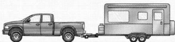
natural_image
Side-view illustration of a pickup truck and a campfire vehicle (no text or symbols)FIG 2. WITH WEIGHT DISTRIBUTION
8181f965
EXAMPLE ONLY

natural_image
Side profile illustration of a pickup truck with a trailer on its side (no text or symbols)FIG. 3 IMPROPER ADJUSTMENT (INCORRECT)
8181f96f
WeightDistributingHitchSystemImproperAdjustmentofWeightDistributingSystem
TrailerHitchClassification
Your vehicle may be factory equipped for safe towing of trailers weighing over 3,500 lbs (1 587 kg) with the optional Trailer Tow Prep Package. See your dealer for package content.
The following chart provides the industry standard for the maximum trailer weight a given trailer hitch class can tow and should be used to assist you in selecting the correct trailer hitch for your intended towing condition. Refer to the Trailer Towing Weights (Maximum Trailer Weight Ratings) chart for the Max. GTW towable for your given drivetrain.
| TrailerHitchClassification | |
| ClassMax.GTW(Gross Trailer Wt.) | |
| Class I - Light Duty 2,000 lbs (907 kg) | |
| Class II - Medium Duty | 3,500 lbs (1 587 kg) |
| Class III - Heavy Duty 5,000 lbs (2 268 kg) | |
| Class IV - Extra Heavy Duty | 10,000 lbs (4 540 kg) |
All trailer hitches should be professionally installed on your vehicle.
TrailerTowingWeights(MaximumTrailerWeightRatings)
The following chart provides the maximum trailer weight ratings towable for your given drivetrain.
| Engine/Transmission | GCWR(GrossCombined Wt.Rating) | FrontalAreaMax | GTW(Gross TrailerWt.) | Max.TongueWt. (SeeNote1) |
| 6.1L Automatic 8 | 800 lbs (3 992 kg) 40 Sq. Ft. | (3.72 square meters) | 3,500 lbs (1 587 kg) 350 | lbs (159 kg) |
| Refer to local laws for maximum trailer towing speeds. | ||||
Note 1 – The trailer tongue weight must be considered as part of the combined weight of occupants and cargo, and should never exceed the weight referenced on the Tire and Loading Information placard. Refer to the Tire–Safety Information Section in this manual.
TrailerandTongueWeight
Always load a trailer with 60% to 65% of the weight in the front of the trailer. This places 10% to 15% of the Gross Trailer Weight (GTW) on the tow hitch of your vehicle. Loads balanced over the wheels or heavier in the rear can cause the trailer to sway severelyside to side which will cause loss of control of vehicle and trailer. Failure to load trailers heavier in front is the cause of many trailer accidents.
Never exceed the maximum tongue weight stamped on your trailer hitch.
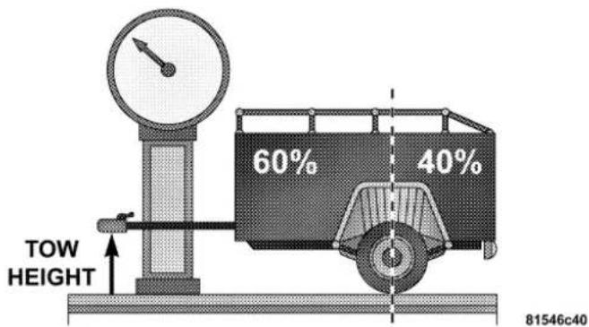
Consider the following items when computing the weight on the front/rear axles of the vehicle:
• The tongue weight of the trailer.
- The weight of any other type of cargo or equipment put in or on your vehicle.
• The weight of the driver and all passengers.
NOTE: Remember that everything put into or on the trailer adds to the load on your vehicle. Also, additional factory-installed options, or dealer-installed options, must be considered as part of the total load on your vehicle. Refer to the Tire and Loading Information placard in the Tire Safety Information Section of this manual for the maximum combined weight of occupants and cargo for your vehicle.
To promote proper break-in of your new vehicle drivetrain components the following guidelines are recommended:
CAUTION!
- Avoidtowingatrailerforthefirst500miles(805 km)ofvehicleoperation.Doingsomaydamage yourvehicle.
- During the first 500 miles (805 km) of trailer towing, limityourspeed to 50 mph (80 km/h).
Perform the maintenance listed in Section 8 of this manual. When towing a trailer, never exceed the GAWR, or GCWR, ratings.
WARNING!
Impropertowingcanleadtoaninjuryaccident. Followtheseguidelinestomakeyourtrailertowing assafeaspossible:
Make certain that the load dissecured in the trailer and will not shift during travel. Whentrailing cargothatis not fully secured, dynamic load shifts can occur that may be difficult for the driver to control. You could lose control of your vehicle and have an accident.
- When hauling cargo or towing a trailer, do not overload your vehicle or trailer. Overloading can cause a loss of control, poor performance or damage to brakes, axle, engine, transmission, steering, suspension, chassis structure or tires.
- Safety chains must always be used between your vehicle and trailer. Always connect the chains to the hook retainers of the vehicle hitch. Cross the chains under the trailer tongue and allow enough slack for turning corners.
- Vehicles with trailers should not be parked on a grade. When parking, apply the parking brake on the tow vehicle. Put the tow vehicle in P (Park). Always, block or "chock" the trailer wheels.
• GCWR must not be exceeded. -
Totalweightmustbedistributedbetweenethetow vehicleandthetrailersuchthatthefollowingfour ratingsarenotexceeded:
-
GVWR
- GTW
-
GAWR
-
Tongue weight rating for the trailer hitch utilized (This requirement may limit the ability to always achieve the 10% to 15% range of tongue weight as a percentage of total trailer weight).
TowingRequirements—Tires
- Proper tire inflation pressures are essential to the safe and satisfactory operation of your vehicle. Refer to "Tires-General Information" for proper tire inflation procedures.
- Also, check the trailer tires for proper tire inflation pressures before trailer usage.
- Check for signs of tire wear or visible tire damage before towing a trailer. Refer to "Tires-General Information" for proper inspection procedure.
- When replacing tires, refer to "Tires-General Information" for proper tire replacement procedures. Replacing tires with a higher load carrying capacity will not increase the vehicle's GVWR and GAWR limits.
TowingRequirements—TrailerBrakes
- Do notinterconnect the hydraulic brake system or vacuum system of your vehicle with that of the trailer. This could cause inadequate braking and possible personal injury.
- An electronically actuated trailer brake controller is required when towing a trailer with electronically actuated brakes. When towing a trailer equipped with a hydraulic surge actuated brake system, an electronic brake controller is not required.
- Trailer brakes are recommended for trailers over 1,000 lbs (454 kg) and required for trailers in excess of 2,000 lbs (907 kg).
CAUTION!
If the trailer weighsmorethan 1,000 lbs (454 kg) loaded, it should have its own brakes and they should be of adequate capacity. Failure to this could lead to accelerated brakelining wear, higher brake pedaleffort, and longer stopping distances.
WARNING!
Donotconnecttrailerbrakestoyourvehicle'shydraulicbrakelines.Itcanoverloadyourbrakesystemandcauseittofail.Youmightnothavebrakes whenyouneedthemandcouldhaveanaccident. Towinganytrailerwillincreaseyourstoppingdistance.Whentowingyoushouldallowforadditional spacebetweenyourvehicleandthevehicleinfront ofyou.Failurertodosocouldresultinanaccident.
TowingRequirements—TrailerLights&Wiring
Whenever you pull a trailer, regardless of the trailer size, stop lights and turn signals on the trailer are required for motoring safety.
The Trailer Tow Package may include a 4 and 7 pin wiring harness. Use a factory approved trailer harness and connector.
The electrical connections are all complete to the vehicle but you must mate the harness to a trailer connector. Refer to the following illustrations.

flowchart
graph LR
    A["RIGHT STOP/TURN"] --> B["○"]
    C["LEFT STOP/TURN"] --> D["○"]
    E["PARK"] --> F["○"]
    G["GND"] --> H["○"]
    B --> I["FEMALE PINS"]
    D --> I
    F --> J["MALE PIN"]
    H --> J
Before setting out on a trip, practice turning, stopping and backing the trailer in an area away from heavy traffic.
TowingTips—AutomaticTransmission
The "D" range can be selected when towing. However, if frequent shifting occurs while in this range, the "3" range should be selected.
NOTE: Using the "3" range while operating the vehicle under heavy operating conditions will improve performance and extend transmission life by reducing excessive shifting and heat build up. This action will also provide better engine braking.
The automatic transmission fluid and filter should be changed if you REGULARLY tow a trailer for more than 45 minutes of continuous operation. See Schedule "B" in section 8 of this manual for transmission fluid change intervals.
NOTE: Check the automatic transmission fluid level before towing.
TowingTips—ElectronicSpeedControl(If Equipped)
- Don't use in hilly terrain or with heavy loads.
- When using the speed control, if you experience speed drops greater than 10 mph (16 km/h), disengage until you can get back to cruising speed.
- Use speed control in flat terrain and with light loads to maximize fuel efficiency.
TowingTips—CoolingSystem
To reduce potential for engine and transmission overheating, take the following actions:
- City Driving
When stopped for short periods of time, put transmission in neutral and increase engine idle speed.
- Highway Driving
Reduce speed.
- Air Conditioning
Turn off temporarily.
– refer to Cooling System Operating information in the Maintenance section of this manual for more information.
RECREATIONAL TOWING(BEHIND MOTORHOME, ETC.)
Recreationaltowingisnotallowed.
WHATODOINEMERGENCIES
CONTENTS
■Hazard Warning Flashers....292
■If Your Engine Overheats....293
■Jump Starting 293
■Jump Starting 293
292WHATODOINEMERGENCIES
Your vehicle's hazard warning flasher is an emergency warning system. When you activate it, all front and rear directional signals will flash intermittently. Use it when your vehicle is disabled on or near the road. It warns other drivers to steer clear of you and your vehicle. This is an emergency warning system, not to be used when the vehicle is in motion.
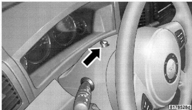
natural_image
Interior view of a car dashboard and steering wheel (no visible text or symbols)HazardWarningSwitch
To activate the warning flasher, push down on the button on top of the steering column until it latches. To turn the warning flasher off, push down again to unlatch the button.
NOTE: With extended use, the flasher may run down your battery.
IFYOURENGINEOVERHEATS
In any of the following situations, you can reduce the potential for overheating by taking the appropriate action.
- On the highways — Slow down.
- In city traffic — While stopped, put transmission in N (Neutral), but do not increase engine idle speed.
NOTE: There are steps that you can take to slow down an impending overheat condition. If your air conditioner is on, turn it off. The air conditioning system adds heat to the engine cooling system and turning off the A/C removes this heat. You can also turn the Temperature Control to maximum heat, the Mode Control to floor, and the Fan Control to High. This allows the heater core to act as a supplement to the radiator and aids in removing heat from the engine cooling system.
CAUTION!
Drivingwithahotcoolingsystemcoulddamage yourvehicle.Ifthetemperaturegaugereads“H”, pulloverandstopthevehicle.Idlethevehiclewith theairconditionerturnedoffuntilthepointerdrops backintothenormalrange.Ifthepointerremainson the“H”, andyouhearcontinuouschimes, turnthe engineoffimmediately, andcallforservice.
JUMPSTARTING
If the vehicle has a discharged battery, booster cables may be used to obtain a start from a booster battery or the battery in another vehicle. This type of start can be dangerous if done improperly, so follow this procedure carefully.
WARNING!
Batteryfluidisacorrosiveacidsolution;donot allowbatteryfluidtocontacteyes,skinorclothing.
Don'tleanoverbatterywhenattachingclampsor allowtheclampstotoucheachother.Ifacidsplashes ineyesoronskin,flushcontaminatedareaimmediatelywithlargequantitiesofwater.
Abatterygenerateshydrogengaswhichisflammableandexplosive.Keepflameorsparkaway fromtheventholes.
Donotuseaboosterbatteryoranyotherbooster sourcethathasagreaterthan12voltsystem,i.e.Do notusea24voltpowersource.
-
Remove all metal jewelry such as watch bands or bracelets which might make an unintended electrical contact.
-
Park the booster vehicle within cable reach but without letting the vehicles touch. Set the parking brake on both vehicles, place the transmission in P (Park), and turn the ignition OFF.
- Turn off the heater, radio, and all unnecessary electrical loads.
- Connect one end of a jumper cable to the positive terminal of the booster battery. Connect the other end of the same cable to the positive terminal of the discharged battery.
WARNING!
Donotpermitvehiclestotoucheachotherasthis couldestablishgroundconnectionandpersonal injurycouldresult.
- Remove all metal jewelry such as watch bands or bracelets which might make an unintended electrical contact.
- Park the booster vehicle within cable reach but without letting the vehicles touch. Set the parking brake on both vehicles, place the transmission in P (Park), and turn the ignition OFF.
- Turn off the heater, radio, and all unnecessary electrical loads.
- Connect one end of a jumper cable to the positive terminal of the booster battery. Connect the other end of the same cable to the positive terminal of the discharged battery.
WARNING!
Donotpermitvehiclestotoucheachotherasthis couldestablishagroundconnectionandpersonal injurycouldresult.
- Connect the other cable, first to the negative terminal of the booster battery and then to the engine of the vehicle with the discharged battery. Make sure you have a good contact on the engine.
- Start the engine in the vehicle which has the booster battery, let the engine idle a few minutes, then start the engine in the vehicle with the discharged battery.
- When removing the jumper cables, reverse the above sequence exactly. Be careful of the moving belts and fan.
WARNING!
Anyprocedureotherthanabovecouldresultin:
- Personal injury caused by electrolytes squirting out the battery vent;
- Personal injury or property damaged duetobattery explosion;
- Damagetochargingsystemofboostervehicleor ofimmobilizedvehicle.
WARNING!
- Youshouldnottrytostartyourvehiclebypushingortowing.
- Donotconnectthecabletothenegativepostof thedischargebattery. Theresultingelectrical sparkcouldcausethebatterytoexplode.
- Duringcoldweatherwhentemperaturesarebelowfreezingpoint,electrolyteinadischarged batterymayfreeze.Donotattemptjumpstarting becausethebatterycouldruptureorexplode.The batterytemperaturemustbebroughtupabove freezingpointbeforeattemptingjumpstart.
MAINTAINING YOUR VEHICLE
CONTENTS
■Engine Compartment-6.1L....300
■Onboard Diagnostic System — OBD II . . . . . . . 3 0 1
□Loose Fuel Filler Cap Message....302
■Emissions Inspection And Maintenance Programs 302
■Replacement Parts....304
■Dealer Service....304
■Maintenance Procedures....305
□Engine Oil 305
□Engine Oil Filter....308
□Drive Belts — Check Condition And Tensioner....309
□Spark Plugs....309
□Engine Air Cleaner Filter....3 1 0
□Fuel Filter 310
□Catalytic Converter....310
□Maintenance-Free Battery....3 1 2
□Air Conditioner Maintenance....3 1 3
298MAINTAININGYOURVEHICLE
□Power Steering Fluid Check....3 1 4
□Body Lubrication....3 1 6
□Windshield Wiper Blades....3 1 6
□Windshield Washers — Front And Rear ..... 3 1 6
□Exhaust System....317
□Cooling System....318
□Hoses And Vacuum/Vapor Harnesses ..... 3 2 3
□Brake System....324
□Brake Fluid Level Check....3 2 5
□Fuel System Hoses....327
□Automatic Transmission....3 2 7
□Front And Rear Wheel Bearings....3 2 9
□Appearance Care And Protection From Corrosion....3 2 9
■Fuse Panel 333
□Interior Fuses....3 3 3
□Underhood Fuses
(Power Distribution Center) 3 3 6
□Underhood Fuses
(Integrated Power Module) 3 3 8
■ Vehicle Storage ....339
■Replacement Bulbs....340
■ Bulb Replacement .....341
□Head Light 341
□Front Turn Signal....342
MAINTAINING YOUR VEHICLE299
□Front Fog Light....343
☐Rear Tail, Stop, Turn Signal, And Back-Up Lights 344
□Center High Mounted Stop Light (CHMSL) ... 345
■Fluid Capacities....346
■Fluids, Lubricants, And Genuine Parts ..... 3 4 7
□Engine 347
□Chassis....348
300MAINTAININGYOURVEHICLE
ENGINECOMPARTMENT-6.1L

ONBOARDDIAGNOSTICSYSTEM—OBDII
Your vehicle is equipped with a sophisticated onboard diagnostic system called OBD II. This system monitors the performance of the emissions, engine, and automatic transmission control systems. When these systems are operating properly, your vehicle will provide excellent performance and fuel economy, as well as engine emissions well within current government regulations.
If any of these systems require service, the OBD II system will turn on the “Malfunction Indicator Light.” It will also store diagnostic codes and other information to assist your service technician in making repairs. Although your vehicle will usually be drivable and not need towing, see your dealer for service as soon as possible.
CAUTION!
- Prolongeddrivingwiththe"MalfunctionIndicatorLight"oncouldcausefurtherdamagetothe emissioncontrolsystem.Itcouldalsoaffectfuel economyanddriveability.Thevehiclemustbe servicedbeforeanyemissionstestscanbeperformed.
- Ifthe"MalfunctionIndicatorLight"isflashing whiletheengineisrunning,severecatalyticconverterdamageandpowerlosswillsoonoccur. Immediateserviceisrequired.
After fuel is added, the vehicle diagnostic system can determine if the fuel filler cap is loose, improperly installed, or damaged. A "CHECK GASCAP" message will be displayed in the EVIC (Refer to Section 4 of this manual). Tighten the gas cap until a "clicking" sound is heard. This is an indication that the gas cap is properly tightened.
This message may be temporarily overridden by pressing either the C/T, STEP, or MENU buttons. However, after one minute of no customer interaction, the EVIC will display again the "CHECK GASCAP" message. The message will remain displayed until the vehicle diagnostic system can retest the fuel system. The test will perform the next time the vehicle is started, if the vehicle was keyed off above 40°F (4°C) outside temperature and the following vehicle start is above 40°F (4°C) outside temperature. It may be possible to have a message that will not clear due to the test being disabled due to low outside temperatures. If the test is performed and the problem is gone, the message will disappear.
If the problem persists, the message will appear the next time the vehicle is started. This might indicate a damaged cap. If the problem is detected twice in a row, the system will turn on the Malfunction Indicator Light (MIL).
Resolving the problem will turn the MIL light off. See your authorized dealer for service.
EMISSIONSINSPECTIONANDMAINTENANCE PROGRAMS
In some localities, it may be a legal requirement to pass an inspection of your vehicle's emissions control system. Failure to pass could prevent vehicle registration.

For states which have an I/M (Inspection and Maintenance) requirement, this check verifies the following: the MIL (Malfunction Indicator Lamp)
is functioning and is not on when the engine is running, and that the OBD (On Board Diagnostic) system is ready for testing.
Normally, the OBD system will be ready. The OBD system may not be ready if your vehicle was recently serviced, if you recently had a dead battery, or a battery replacement. If the OBD system should be determined not ready for the I/M test, your vehicle may fail the test.
Your vehicle has a simple ignition key actuated test which you can use prior to going to the test station. To check if your vehicle's OBD system is ready, you must do the following:
- Insert your ignition key into the ignition switch.
- Turn the ignition to the ON position, but do not crank or start the engine.
-
If you crank or start the engine, you will have to start this test over.
-
As soon as you turn your key to the ON position, you will see your MIL symbol come on as part of a normal bulb check.
- Approximately 15 seconds later, one of two things will happen:
a. The MIL will flash for about 10 seconds and then return to being fully illuminated until you turn off the ignition key or start the engine. This means that your vehicle's OBD system is not ready and you should not proceed to the I/M station.
b. The MIL will not flash at all and will remain fully illuminated until you turn off the ignition key or start the engine. This means that your vehicle's OBD system is ready and you can proceed to the I/M station.
If your OBD system is notready, you should see your authorized dealer or repair facility. If your vehicle was recently serviced or had a battery failure or replacement,
you may need to do nothing more than drive your vehicle as you normally would in order for your OBD system to update. A recheck with the above test routine may then indicate that the system is now ready.
Regardless of whether your vehicle's OBD system is ready or not ready, if the MIL symbol is illuminated during normal vehicle operation, you should have your vehicle serviced before going to the I/M station. The I/M station can fail your vehicle because the MIL symbol is on with the engine running.
REPLACEMENTPARTS
Use of genuine Mopar® parts for normal/scheduled maintenance and repairs is highly recommended to insure the designed performance. Damage or failures caused by the use of non-Mopar® parts for maintenance and repairs will not be covered by the manufacturer's warranty.
DEALERSERVICE
Your dealer has the qualified service personnel, special tools and equipment to perform all service operations in an expert manner. Service Manuals are available which include detailed service information for your vehicle. Refer to these manuals before attempting any procedure yourself.
NOTE: Intentional tampering with emissions control systems can result in civil penalties being assessed against you.
WARNING!
Youcanbebadlyinjuredworkingonorarounda motorvehicle.Doonlythatserviceworkforwhich youhavetheknowledgeandtheproperequipment. Ifyouhaveanydoubtaboutyourabilitytoperform aservicejob,takeyourvehicletoacompetent mechanic.
MAINTENANCEPROCEDURES
The pages that follow contain the required maintenance services determined by the engineers who designed your vehicle.
Besides the maintenance items for which there are fixed maintenance intervals, there are other items that should operate satisfactorily without periodic maintenance. However, if a malfunction of these items does occur, it
could adversely affect the engine or vehicle performance. These items should be inspected if a malfunction is observed or suspected.
EngineOil
CheckingOilLevel
To assure proper engine lubrication, the engine oil must be maintained at the correct level. Check the oil level at regular intervals, such as every fuel stop.
The best time to check the engine oil level is about 5 minutes after a fully warmed engine is shut off or before starting the engine after it has sat overnight.
Checking the oil while the vehicle is on level ground will improve the accuracy of the oil level readings. Maintain the oil level in the "SAFE" range. Adding one quart of oil when the reading is at the bottom of the "SAFE" range will result in an oil level at the top of the "SAFE" range on these engines.
306MAINTAININGYOURVEHICLE
NOTE: Fill engine oil one quart at a time.

EngineOilDipstick
8131ee6a
| CAUTION! |
| Overfillingorunderfillingwillcauseoilaerationor lossofoilpressure.Thiscoulddamageyourengine. |
| CAUTION! |
| Operatingtheenginewiththeoillevelsbelowthe safezone,oroperatingwithoillevelsthatexceedthe topofthesafezonemaycauseenginedamage. |
ChangeEngineOil
Road conditions and your kind of driving affects the interval at which your oil should be changed. Check the following list to see if any apply to you.
• Day or night temperatures are below 32irc F ( 0irc C).
- Stop and go driving.
- Extensive engine idling.
- Driving in dusty conditions.
- Short trips of less than 10 miles (16 km).
- More than 50% of your driving is at sustained high speeds during hot weather, above 90°F (32°C).
- Trailer towing.
NOTE: If ANY of these apply to you then change your engine oil every 3,000 miles (5 000 km) or 3 months, whichever comes first. Refer to "Maintenance Schedule B" in Section 8 of this manual.
If none of these apply to you, then change your engine oil at every interval shown on "Maintenance Schedule "A." Refer to Section 8 of this manual.
NOTE: Under no circumstances should oil change intervals exceed 6,000 miles (10 000 km) or 6 months whichever comes first.
EngineOilSelection
For best performance and maximum protection under all types of operating conditions, the manufacturer only recommends full synthetic engine oils that are API rated as SM/CF and meet the requirements of DaimlerChrysler Material Standard MS-10725. Use Mopar or an equivalent oil meeting the specification MS-10725.
The manufacturer recommends the use of a full synthetic engine oil, such as Mobil 1®SAE 0W-40 or equivalent.
308MAINTAININGYOURVEHICLE
EngineOilViscosityChart
The proper SAE viscosity grade of engine oil should be selected based on the following recommendation and be within the operating temperature shown in the engine oil viscosity chart.

other
| Temperature Range Before Oil Change | Value | | ----------------------------------- | ----- | | -20° to 0° | -29° to -18° | | 0° to 10° | -18° to -12° | | 10° to 20° | -12° to -7° | | 20° to 32° | -7° to 0° | | 32° to 60° | 0° to 16° | | 60° to 80° | 16° to 27° | | 80° to 100° | 38° to 100° |MaterialsAddedtoEngineOil
The manufacturer strongly recommends against the addition of any additives (other than leak detection dyes) to the engine oil. Engine oil is an engineered product and it's performance may be impaired by supplemental additives.
Disposing of Used Engine Oil And Oil Filters
Care should be taken in disposing of used engine oil and oil filters from your vehicle. Used oil and oil filters, indiscriminately discarded, can present a problem to the environment. Contact your dealer, service station, or governmental agency for advice on how and where used oil and oil filters can be safely discarded in your area.
EngineOilFilter
The engine oil filter should be replaced at every engine oil change.
EngineOilFilterSelection
The manufacturer's engines have a full-flow type oil filter. Use a filter of this type for replacement. The quality of replacement filters varies considerably. Only high quality filters should be used to assure most efficient service. Mopar Engine Oil Filters are a high quality oil filter and are recommended.
DriveBelts—CheckConditionandTensioner
Belt tension is controlled by means of an automatic tensioner. No belt tension adjustments are required. However, belt and belt tensioner condition should be inspected at the specified intervals, and replaced if required. See your authorized dealer for service.
At the mileage indicated on the appropriate “Maintenance Schedule,” all belts and tensioner should be checked for condition. Improper belt tension can cause belt slippage and failure.
Belts should be inspected for evidence of cuts, cracks, glazing, or frayed cords and replaced if there is indication of damage which could result in belt failure. Low generator belt tension can cause battery failure.
Also check belt routing to make sure there is no interference between the belts and other engine components.
SparkPlugs
Spark plugs must fire properly to assure engine performance and emission control. New plugs should be installed at the specified mileage. The entire set should be replaced if there is any malfunction due to a faulty spark plug. Malfunctioning spark plugs can damage the catalytic converter. For proper type of replacement spark plugs, refer to the “Vehicle Emission Control Information” label in the engine compartment.
310MAINTAININGYOURVEHICLE
EngineAirCleanerFilter
Under normal driving conditions, replace the air filter at the intervals shown on “Maintenance Schedule A.” If, however, you drive the vehicle frequently under dusty or severe conditions, the filter element should be inspected periodically and replaced if necessary at the intervals shown on “Maintenance Schedule B.”
WARNING!
Theaircleanercanprovideameasureofprotection in the caseofenginebackfire.Donotremovetheair cleanerunlesssuchremovalisnecessaryforrepairor maintenance.Makesurethatnooneisnearthe enginecompartmentbeforestartingthevehiclewith theaircleanerremoved.Failureretodosocanresultin seriouspersonalinjury.
FuelFilter
A plugged fuel filter can cause stalling, limit the speed at which a vehicle can be driven or cause hard starting. Should an excessive amount of dirt accumulate in the fuel tank, filter replacement may be necessary. See your local dealer for service.
CatalyticConverter
The catalytic converter requires the use of unleaded fuel only. Leaded gasoline will destroy the effectiveness of the catalyst as an emission control device.
Under normal operating conditions, the catalytic converter will not require maintenance. However, it is important to keep the engine properly tuned to assure proper catalyst operation and prevent possible catalyst damage.
CAUTION!
Damagetothecatalyticconvertercanresultifyour vehicleisnotkeptinproperoperatingcondition.In theeventofenginemalfunction,particularlyinvolvingenginemisfireorotherapparentlossofperformance,haveyourvehicleservicedpromptly.Continuedoperationofyourvehiclewithasevere malfunctioncouldcausetheconvertertooverheat, resultinginpossibledamagetotheconverterandthe vehicle.
NOTE: Intentional tampering with emissions control systems can result in civil penalties being assessed against you.
WARNING!
Ahotexhaustsystemcanstartafireifyouparkover materialsthatcanburn.Suchmaterialsmightbe grassorleavescomingintocontactwithyourex-haustsystem.Donotparkoroperateyourvehiclein areaswhereyourexhaustsystemcancontactanythingthatcanburn.
In unusual situations involving grossly malfunctioning engine operation, a scorching odor may indicate severe and abnormal catalyst overheating. If this occurs, the vehicle should be stopped, the engine shut off and the vehicle allowed to cool. Thereafter, service, including a tune-up to manufacturer's specifications, should be obtained immediately.
To minimize the possibility of catalyst damage:
- Do not shut off the engine or interrupt the ignition when the transmission is in gear and the vehicle is in motion.
- Do not try to start engine by pushing or towing the vehicle.
- Do not idle the engine with any spark plug wires disconnected or removed, such as when diagnostic testing, or for prolonged periods during very rough idling or malfunctioning operating conditions.
Maintenance-FreeBattery
Your vehicle is equipped with a maintenance-free battery. You will never have to add water, nor is periodic maintenance required.
WARNING!
Batteryposts,terminals,andrelatedaccessoriescontainleadandleadcompounds.Alwayswashhands afterhandlingthebattery.

8000cbce
To determine the battery charge, check the battery test indicator (if equipped) on top of the battery. Refer to the illustration.
CAUTION!
Itisessentialwhenreplacingthecablesonthe batterythatthepositivecableisattachedtothe positivepostandthenegativecableisattachedtothe negativepost.Batterypostsaremarked(+)positive andnegative(-)andidentifiedonthebatterycase. Also,ifa"fastcharger"isusedwhilebatteryisinthe vehicle,disconnectbothvehiclebatterycablesbeforeconnectingthechargertobattery.Donotusea "fastcharger"toprovidestartingvoltage.
AirConditionerMaintenance
For best possible performance, your air conditioner should be checked and serviced by an Authorized Dealer at the start of each warm season. This service should include cleaning of the condenser fins and a performance test. Drive belt tension should also be checked at this time.
WARNING!
- Useonlyrefrigerantsandcompressorlubricants approvedbythemanufacturerforyourairconditioningsystem.Someunapprovedrefrigerantsare flammableandcanexplode,injuringyou.Other unapprovedrefrigerantsorlubricantscancause thesystemtofail,requiringcostlyrepairs.Refer totheWarrantyInformationBookforfurther warrantyinformation.
- Theairconditioningsystemcontainsrefrigerant underhighpressure.Toavoidriskofpersonal injuryordamagetothesystem,addingrefrigerant oranyrepairrequiringlinestobedisconnected shouldbedonebyanexperiencedrepairman.
Refrigerant Recovery and Recycling
R-134a Air Conditioning Refrigerant is a hydrofluorocarbon (HFC) that is endorsed by the Environmental Protection Agency and is an ozone-saving product. However, the manufacturer recommends that air conditioning service be performed by dealers or other service facilities using recovery and recycling equipment.
NOTE: Use only manufacturer approved A/C System Sealers, Stop Leak Products, Seal Conditioners, Compressor Oil, or Refrigerants.
PowerSteeringFluidCheck
The power steering system requires the use of Mopar® Hydraulic System Power Steering Fluid (P/N 05142893AA), or equivalent, which meets DaimlerChrysler Material Standard MS-10838.
CAUTION!
DonotuseAutomaticTransmissionFluid(ATF)or othertypesofpowersteeringfluidswhenservicing thepowersteeringsystemofthisvehicle.Damageto thepowersteeringsystemcanresultfromtheuseof thewrongpowersteeringfluid.
Checking the power steering fluid level at a defined service interval is not required. The fluid should only be checked if a leak is suspected, abnormal noises are apparent, and/or the system is not functioning as anticipated. Coordinate inspection efforts through a certified "DaimlerChrysler Dealership."
WARNING!
Fluidlevelshouldbecheckedonalevelsurfacewith theengineofftopreventinjuryfrommovingparts, andtoinsureaccuratefluidlevelreading.Donot overfill.Useonlythemanufacturer'srecommended fluid.
If necessary, add fluid to restore to the proper indicated level. With a clean cloth, wipe any spilled fluid from all surfaces. Refer to Fluids, Lubricants, and Genuine Parts for correct fluid type.
NOTE: Upon initial start-up in cold weather, the power steering pump may make noise for a short period of time. This is due to the cold, thick fluid in the steering system. This noise should be considered normal, and does not in any way damage the steering system.
316MAINTAININGYOURVEHICLE
BodyLubrication
Locks and all body pivot points, including such items as seat tracks, doors, trunk and hood hinges, should be lubricated periodically to assure quiet, easy operation and to protect against rust and wear. Prior to the application of any lubricant, the parts concerned should be wiped clean to remove dust and grit; after lubricating excess oil and grease should be removed. Particular attention should also be given to hood latching components to insure proper function. When performing other underhood services, the hood latch, release mechanism and safety catch should be cleaned and lubricated.
The external lock cylinders should be lubricated twice a year, preferably in the fall and spring. Apply a small amount of a high quality Mopar ® Lock Cylinder Lubricant or equivalent directly into the lock cylinder.
WindshieldWiperBlades
The rubber edges of the wiper blades and the windshield should be cleaned periodically with a sponge or soft cloth and a mild nonabrasive cleaner. This will remove accumulations of salt or road film.
Operation of the wipers on dry glass for long periods may cause deterioration of the wiper blades. Always use washer fluid when using the wipers to remove salt or dirt from a dry windshield.
Avoid using the wiper blades to remove frost or ice from the windshield. Keep the blade rubber out of contact with petroleum products such as engine oil, gasoline, etc.
WindshieldWashers—FrontandRear
On vehicles equipped with a Electronic Vehicle Information Center (EVIC), the low washer fluid level will be indicated. When the sensor detects a low fluid level, the windshield will light on the vehicle graphic outline and
the "Washer Fluid Low" message will be displayed. Refer to "Electronic Vehicle Information Center" in Section 4 of this manual.
The fluid reservoir for the windshield washers and the rear window washer is shared. It is located in the front of the engine compartment on the passenger side and should be checked for fluid level at regular intervals. Fill the reservoir with windshield washer solvent (not antifreeze/coolant) and operate the system for a few seconds to flush out the residual water.
WARNING!
Commerciallyavailablewindshieldwashersolvents areflammable. They could ignite and burn you. Care must be exercised when filling or working around the washers solution.
ExhaustSystem
The best protection against carbon monoxide entry into the vehicle body is a properly maintained engine exhaust system.
Whenever a change is noticed in the sound of the exhaust system, when exhaust fumes can be detected inside the vehicle, or when the underside or rear of the vehicle is damaged, have a competent mechanic inspect the complete exhaust system and adjacent body areas for broken, damaged, deteriorated, or mispositioned parts. Open seams or loose connections could permit exhaust fumes to seep into the passenger compartment. In addition, inspect the exhaust system each time the vehicle is raised for lubrication or oil change. Replace as required.
WARNING!
Exhaustgasescaninjureorkill. They contain carbon monoxide(CO) which is colorless and odorless. Breathing it can make you unconscious and can eventually poison you. To avoid breathing CO, follow the precedings safety tips.
CoolingSystem
WARNING!
- Whenworkingneartheradiatorcoolingfan, disconnect the fan motor lead to turn the ignition switch to the OFF position. The fan is temperature controlled and can start at any time the ignition switch in the ON position.
- Youorotherscanbebadlyburnedbyhotcoolant orsteamfromyourradiator.Ifyouseeorhear steamcomingfromunderthehood,don'topen thehooduntiltheradiatorhashadtimetocool. Nevertrytoopenacoolingsystempressurecap whentheradiatorishot.
CoolantChecks
Check engine coolant (antifreeze) protection every 12 months (before the onset of freezing weather, where
applicable). If coolant is dirty or rusty in appearance, the system should be drained, flushed and refilled with fresh coolant. Check the front of the A/C condenser for any accumulation of bugs, leaves, etc. If dirty, clean by gently spraying water from a garden hose vertically down the face of the condenser.
Check the coolant recovery bottle tubing for brittle rubber, cracking, tears, cuts and tightness of the connection at the bottle and radiator. Inspect the entire system for leaks.
With the engine at normal operating temperature (but not running), check the cooling system pressure cap for proper vacuum sealing by draining a small amount of coolant from the radiator drain cock. If the cap is sealing properly, the engine coolant (antifreeze) will begin to drain from the coolant recovery bottle. DO NOT REMOVE THE COOLANT PRESSURE CAP WHEN THE COOLING SYSTEM IS HOT.
CoolingSystem—Drain, Flushand Refill
At the intervals shown on the appropriate “Maintenance Schedule,” the system should be drained, flushed and refilled.
If the solution is dirty or contains a considerable amount of sediment, clean and flush with a reliable cooling system cleaner. Follow with a thorough rinsing to remove all deposits and chemicals. Properly dispose of old antifreeze solution.
SelectionOfCoolant
Use only the manufacturer's recommended coolant, refer to Fluids, Lubricants and Genuine Parts for correct coolant type.
CAUTION!
MixingofcoolantsotherthanspecifiedHOATenginecoolants, may result in engined damage and may decrease corrosion protection. If an - HOATcoolant is introduced into the cooling system in an emergency, it should be replaced with the specified coolant as soon as possible.
Donotuseplainwateraloneoralcoholbaseengine coolant(antifreeze)products.Donotuseadditional rustinhibitorsorantirustproducts,astheymaynot becompatiblewiththeradiatorenginecoolantand mayplugtheradiator.
This vehicle has not been designed for use with Propylene Glycol based coolants. Use of Propylene Glycol based coolants is not recommended.
AddingCoolant
Your vehicle has been built with an improved engine coolant that allows extended maintenance intervals. This coolant can be used up to 5 Years or 100,000 miles before replacement. To prevent reducing this extended maintenance period, it is important that you use the same coolant throughout the life of your vehicle. Please review these recommendations for using Hybrid Organic Additive Technology (HOAT) coolant.
When adding coolant, a minimum solution of 50% recommended Mopar Antifreeze/ Coolant 5 Year/100,000 Mile Formula HOAT (Hybrid Organic Additive Technology), or equivalent, in water should be used. Use higher concentrations (not to exceed 70%) if temperatures below -34ircF ( -37ircC ) are anticipated.
Use only high purity water such as distilled or deionized water when mixing the water/engine coolant solution.
The use of lower quality water will reduce the amount of corrosion protection in the engine cooling system.
Please note that it is the owner's responsibility to maintain the proper level of protection against freezing according to the temperatures occurring in the area where the vehicle is operated.
NOTE: Mixing coolant types will decrease the life of the engine coolant and will require more frequent coolant changes.
CoolingSystemPressureCap
The cap must be fully tightened to prevent loss of coolant, and to insure that coolant will return to the radiator from the coolant recovery bottle.
The cap should be inspected and cleaned if there is any accumulation of foreign material on the sealing surfaces.
WARNING!
- Thewarningwords "DONOTOPENHOT" on thecoolingsystempressurecapareasafetyprecaution. Neveraddcoolantwhentheengineis overheated. Donotloosenorremovethecapto coolanoverheatedengine. Heatcausespressure tobuildupinthecoolingsystem. Toprevent scaldingorinjury, donotremovethepressurecap whilethesystemishotorunderpressure.
- Donotuseapressurecapotherthantheone specifiedforyourvehicle.Personalinjuryor enginedamagemayresult.
DisposalofUsedEngineCoolant
Used ethylene glycol based engine coolant is a regulated substance requiring proper disposal. Check with your local authorities to determine the disposal rules for your community. To prevent ingestion by animals or children
322MAINTAINING YOUR VEHICLE
do not store ethylene glycol based engine coolant in open containers or allow it to remain in puddles on the ground. If ingested by a child, contact a physician immediately. Clean up any ground spills immediately.
CoolantLevel
The coolant bottle provides a quick visual method for determining that the coolant level is adequate. With the engine off and cold, the level of the coolant in the bottle should be between the ranges indicated on the bottle.
The radiator normally remains completely full, so there is no need to remove the radiator cap unless checking for coolant freeze point or replacing coolant. Advise your service attendant of this. As long as the engine operating temperature is satisfactory, the coolant bottle need only be checked once a month.
When additional coolant is needed to maintain the proper level, it should be added to the coolant bottle. Do not overfill.
PointsToRemember
NOTE: When the vehicle is stopped after a few miles (a few kilometers) of operation, you may observe vapor coming from the front of the engine compartment. This is normally a result of moisture from rain, snow, or high humidity accumulating on the radiator and being vaporized when the thermostat opens, allowing hot coolant to enter the radiator.
If an examination of your engine compartment shows no evidence of radiator or hose leaks, the vehicle may be safely driven. The vapor will soon dissipate.
- Do not overfill the coolant recovery bottle.
-
Check coolant freeze point in the radiator and in the coolant recovery bottle. If antifreeze needs to be added, contents of coolant recovery bottle must also be protected against freezing.
-
If frequent coolant additions are required, or if the level in the coolant recovery bottle does not drop when the engine cools, the cooling system should be pressure tested for leaks.
- Maintain coolant concentration at 50% HOAT engine coolant (minimum) and distilled water for proper corrosion protection of your engine which contains aluminum components.
- Make sure that the radiator and coolant recovery bottle overflow hoses are not kinked or obstructed.
- Keep the front of the radiator clean. If your vehicle is equipped with air conditioning, keep the front of the condenser clean, also.
- Do not change the thermostat for summer or winter operation. If replacement is ever necessary, install
ONLY the correct type thermostat. Other designs may result in unsatisfactory coolant performance, poor gas mileage, and increased emissions.
HosesAndVacuum/VaporHarnesses
Inspect surfaces of hoses and nylon tubing for evidence of heat and mechanical damage. Hard or soft spots, brittle rubber, cracking, tears, cuts, abrasions, and excessive swelling indicate deterioration of the rubber.
Pay particular attention to those hoses nearest to high heat sources such as the exhaust manifold. Inspect hose routing to be sure hoses do not come in contact with any heat source or moving component which may cause heat damage or mechanical wear.
Insure nylon tubing in these areas has not melted or collapsed.
324MAINTAININGYOURVEHICLE
Inspect all hose connections such as clamps and couplings to make sure they are secure and no leaks are present.
Components should be replaced immediately if there is any evidence of wear or damage that could cause failure.
BrakeSystem
In order to assure brake system performance, all brake system components should be inspected periodically. Suggested service intervals can be found on the appropriate “Maintenance Schedule.” Refer to Section 8 of this manual.
WARNING!
Ridingthebrakescanleadtobrakefailureand possiblyanaccident.Drivingwithyourfootresting orridingonthebrakepedalcanresultinabnormally highbraketemperatures,excessiveliningwear,and possiblebrakedamage.Youwouldn'thaveyourfull brakingcapacityinanemergency.
BrakeAndPowerSteeringHoses
When the vehicle is serviced for scheduled maintenance, inspect surface of hoses and nylon tubing for evidence of heat and mechanical damage. Hard and brittle rubber, cracking, tears, cuts, abrasion, and excessive swelling indicate deterioration of the rubber. Particular attention should be made to examining those hose surfaces nearest to high heat sources, such as the exhaust manifold.
Insure nylon tubing in these areas has not melted or collapsed.
Inspect all hose connections such as clamps and couplings to make sure they are secure and no leaks are present.
NOTE: Often, fluid such as oil, power steering fluid, and brake fluid are used during assembly plant operations to facilitate the assembly of hoses to couplings. Therefore, oil wetness at the hose-coupling area is not necessarily an indication of leakage. Actual dripping of hot fluid when systems are under pressure (during vehicle operation), should be noted before a hose is replaced based on leakage.
NOTE: Inspection of brake hoses should be performed whenever the brake system is serviced and at every engine oil change. Inspect hydraulic brake hoses for surface cracking, scuffing, or worn spots. If there is any evidence of cracking, scuffing, or worn spots, the hose should be replaced immediately! Eventual deterioration of the hose can take place resulting in a possibility of a burst failure.
WARNING!
Wornbrakehosescanburstandcausebrakefailure. Youcouldhaveanaccident.Ifyouseeanysignsof cracking,scuffing,orwornspots,havethebrake hosesreplacedimmediately.
BrakeFluidLevelCheck
The fluid level in the master cylinder should be checked when performing underhood services, or immediately if the brake system warning light indicates system failure.
Clean the top of the master cylinder area before removing the cap. Add fluid to bring the level up to the top of the "FULL" mark on the side of the master cylinder reservoir.
326MAINTAININGYOURVEHICLE
Overfilling of fluid is not recommended because it may cause leaking in the system.
Add enough fluid to bring the level up to the requirements described on the brake fluid reservoir. With disc brakes, fluid level can be expected to fall as the brake pads wear. However, low fluid level may be caused by a leak and a checkup may be needed.
Use only manufacturer's recommended brake fluid, refer to Fluids, Lubricants and Genuine Parts for correct fluid type.
WARNING!
• Overfillingthebrakefluidreservoircanresultin spillingbrakefluidonhotenginepartsandthe brakefluidcatchingfire.
- Useofabrakefluidthathasalowerinitialboiling pointthantherecommendedMOPARDOT3 productorabrakefluidthatisunidentifiedasto FMVSSspecificationmayresultinsuddenbrake failure duringhardprolongedbraking.Youcould haveanaccident.
Use only brake fluid that has been in a tightly closed container to avoid contamination from foreign matter or moisture.
CAUTION!
Donotallowpetroleumbasefluidtocontaminate thebrakefluid, allbrakesealcomponentscouldbe damagedcausingpartialorcompletebrakefailure.
FuelSystemHoses
Electronic Fuel Injection high pressure fuel systems are designed with hoses and quick connect fittings which have unique material characteristics to provide adequate sealing and resist attack by deteriorated gasoline.
You are urged to use only the manufacturer's specified hoses with quick connect fittings, or their equivalent in material and specification, in any fuel system servicing. It is mandatory to replace any damaged hoses or quick connect fittings that have been removed during service.
Care should be taken in installing quick connect fittings to insure they are properly installed and fully connected. See your authorized dealer for service.
AutomaticTransmission
FluidLevelCheck
Regular automatic transmission fluid level checks are not required. For this reason the dipstick is omitted.
If you notice fluid loss or gear shift malfunction, have your authorized dealer check the transmission fluid level.
CAUTION!
Usingatransmissionfluidotherthanthemanufac-turer'srecommendedfluidmaycausedeterioration intransmissionshiftqualityand/ororqueconverter shudder. Usingatransmissionfluidotherthanthat recommendedbythemanufac-turerwillresultin morefrequentfluidandfilterchanges. Refertothe Fluids, Lubricantsand GenuinePartssectionfor correctfluidtype.
CAUTION!
Thefluidlevelispresetatthefactoryanddoesnot requireadjustmentundernormaloperatingconditions.Ifatransmissionfluidleakoccurs,visityour authorizeddealerimmediately.Severedamagetothe transmissionmayoccur.Yourauthorizeddealerhas thepropertoolstoaccuratelyadjustthefluidlevel.
FluidandFilterChanges
Automatic transmission fluid and filter should be changed as follows:
MaintenanceSchedule"A"—No change necessary.
Maintenance Schedule "B" – Every 60,000 miles (100 000 km) change fluid and filter under the following conditions:
- Police, taxi, limousine, commercial type operation, or trailer towing where the vehicle is driven regularly for more than 45 minutes of continuous operation.
If the transmission is disassembled for any reason, the fluid and filter should be changed.
FrontAndRearWheelBearings
Front and rear wheel bearings are permanently sealed. No regular maintenance is required for these components.
AppearanceCareAndProtectionFromCorrosion
ProtectionofBodyandPaintfromCorrosion
Vehicle body care requirements vary according to geographic locations and usage. Chemicals that make roads passable in snow and ice, and those that are sprayed on trees and road surfaces during other seasons, are highly corrosive to the metal in your vehicle.
The following maintenance recommendations will enable you to obtain maximum benefit from the corrosion resistance built into your vehicle.
WhatCausesCorrosion?
Corrosion is the result of deterioration or removal of paint and protective coatings from your vehicle.
The most common causes are:
- Road salt, dirt and moisture accumulation.
• Stone and gravel impact. - Insects, tree sap and tar.
- Salt in the air near seacoast localities.
• Atmospheric fallout/industrial pollutants.
330MAINTAININGYOURVEHICLE
Washing
- Wash your vehicle regularly. Always wash your vehicle in the shade using Mopar®Car Wash or a mild car wash soap, and rinse the panels completely with clear water.
- If insects, tar, or other similar deposits have accumulated on your vehicle, use Mopar®Super Kleen Bug and Tar Remover to remove.
- Use Mopar®Cleaner Wax to remove road film, stains, and to protect your paint finish. Take care never to scratch the paint.
- Avoid using abrasive compounds and power buffing that may diminish the gloss or thin out the paint finish.
| CAUTION! |
| Donotuseabrasiveorstrongcleaningmaterials suchassteelwoolorscouringpowder,whichwill scratchmetalandpaintedsurfaces. |
SpecialCare
- If you drive on salted or dusty roads or if you drive near the ocean, hose off the undercarriage at least once a month.
- It is important that the drain holes in the lower edges of the doors, rocker panels and tailgate must be kept clear and open.
- If you detect any stone chips or scratches in the paint, touch them up immediately. The cost of such repairs is considered the responsibility of the owner.
MAINTAININGYOURVEHICLE331
- If your vehicle is damaged due to an accident or similar cause which destroys the paint and protective coating have your vehicle repaired as soon as possible. The cost of such repairs is considered the responsibility of the owner.
- If you carry special cargo such as chemicals, fertilizers, de-icer salt, etc., assure that such materials are well packaged and sealed.
- If a lot of driving is done on gravel roads, consider mud or stone shields behind each wheel.
- Use Mopar®Touch Up Paint on scratches or chips as soon as possible. Your authorized dealer has touch up paint to match the color of your vehicle.
WheelandWheelTrimCare
All wheels and wheel trim, especially aluminum and chrome plated wheels should be cleaned regularly with a mild soap and water to prevent corrosion. To remove heavy soil, use Mopar® Wheel Cleaner or select a non-abrasive, non-acidic cleaner. Do not use scouring pads, steel wool, a bristle brush or metal polishes. Only Mopar® cleaners are recommended. Do not use oven cleaner. Avoid automatic car washes that use acidic solutions or harsh brushes that may damage the wheels' protective finish.
InteriorCare
Use Mopar®Total Clean to clean fabric upholstery and carpeting.
Interior Trim should be cleaned starting with a damp cloth, a damp cloth with Mopar®Total Clean, then Mopar®Spot & Stain Remover if absolutely necessary. Do not use harsh cleaners or Armorall. Use Mopar®Total Clean to clean vinyl upholstery.
LeatherSeatCare&Cleaning
Mopar®Total Clean is specifically recommended for leather upholstery.
332MAINTAININGYOURVEHICLE
Your leather upholstery can be best preserved by regular cleaning with a damp soft cloth. Small particles of dirt can act as an abrasive and damage the leather upholstery and should be removed promptly with a damp cloth. Stubborn soils can be removed easily with a soft cloth and Mopar®Total Clean. Care should be taken to avoid soaking your leather upholstery with any liquid. Please do not use polishes, oils, cleaning fluids, solvents, detergents, or ammonia based cleaners to clean your leather upholstery. Application of a leather conditioner is not required to maintain the original condition.
WARNING!
Donotusevolatilesolventsforcleaningpurposes. Manyarepotentiallyflammable,andifusedin closedareastheymaycauserespiratoryharm.
GlassSurfaces
All glass surfaces should be cleaned on a regular basis with Mopar®Glass Cleaner or any commercial household-type glass cleaner. Never use an abrasive type cleaner. Use caution when cleaning inside rear windows equipped with electric defrosters. Do not use scrapers or other sharp instruments which may scratch the elements.
When cleaning the rear view mirror, spray cleaner on the towel or rag that you are using. Do not spray cleaner directly on the mirror.
CleaningPlasticInstrumentClusterLenses
The lenses in front of the instruments in this vehicle are molded in clear plastic. When cleaning the lenses, care must be taken to avoid scratching the plastic.
-
Clean with a wet soft rag. A mild soap solution may be used, but do not use high alcohol content or abrasive cleaners. If soap is used, wipe clean with a clean damp rag.
-
Dry with a soft tissue.
SeatBeltMaintenance
Do not bleach, dye or clean the belts with chemical solvents or abrasive cleaners. This will weaken the fabric. Sun damage will also weaken the fabric.
If the belts need cleaning, use Mopar® Total Clean, a mild soap solution, or lukewarm water. Do not remove the belts from the vehicle to wash them.
Replace the belts if they appear frayed or worn or if the buckles do not work properly.
FUSEPANEL
InteriorFuses
The fuse panel is on the lower instrument panel just to the left of the steering column.

natural_image
Interior view of a car showing the side panel, seatbelt, and dashboard (no visible text or symbols)FusePanelLocation
334MAINTAININGYOURVEHICLE
| Cavity | Cartridge Fuse | MiniFuseDescription | |
| 1 30 Amp | Green | Audio Amp (B+) | |
| 2 15 Amp | Blue | Sunroof (B+) | |
| 3 10 Amp | Red | Htd Mirror (EBL) | |
| 4 20 Amp | Yellow | Rr Pwr Out (B+) | |
| 5 Spare | |||
| 6 Spare | |||
| 7 20 Amp | Yellow | Door Locks (B+) | |
| 8 15 Amp | Blue | Steer Col Lock (B+) (ELV) | |
| 9 20 Amp | Yellow | Pwr Outlet (B+) | |
| Cavity | Cartridge Fuse | MiniFuse | Description |
| 10 10 Amp | Red | Final Drive Control Module (FDCM), Heater Ventilation, Air Conditioning (HVAC), Switch Bank, Transfer Case Switch, O/H, Heater Ventilation, Air Conditioning (HVAC) Relay, Rear Park Assist | |
| 11 Spare (B+) | |||
| 12 10 Amp | Red | Door Mods, Mem. Sw, O/H Lamps, IP Courtesy Lamps, Glove Box Lamp (B+) | |
| 13 10 Amp | Red | Autowipe (R/A) | |
| 14 20 Amp | Yellow | Cigar Ltr (R/A) | |
| 15 10 Amp | Red | Tire Pressure Transducers (R/O) | |
| 16 10 Amp | Red | Steering Control Module (SCM), Diag. Connector, Cluster (B+) | |
| 17 15 Amp | Blue | Flipper Glass (B+) | |
| 19 Spare | (R/S) | ||
| 20 10 Amp | Red | Sentry Key Remote Entry Module (SKREEM), Cluster (R/S) | |
| Cavity | Cartridge Fuse | MiniFuseDescription | |
| 21 Spare | (Acc Delay) | ||
| 22 15 Amp | Blue | Rear Wiper (B+) | |
| 24 10 Amp | Red | Power Distribution Center (PDC) Relays, Final Drive Control Module (FDCM), Front Control Module (FCM) (R/S), A580 (R/S) | |
| 25 10 Amp | Red | Shifter Assy (BTSI), Trans. Case Switch, ESP/ABS, Brake Supp Rly Coil (R/S) | |
336MAINTAININGYOURVEHICLE
UnderhoodFuses(PowerDistributionCenter)

natural_image
Close-up of a car engine bay with visible wiring and components (no text or symbols)PowerDistributionCenter
| Cavity | Cartridge Fuse | MiniFuseDescription | |
| 1 40 Amp Green | HVAC Blower | ||
| Cavity | Cartridge Fuse | MiniFuseDescription |
| 2 30 Amp Pink | Power Outlets | |
| 3 30 Amp Pink | Rr Wiper/Ign R/O | |
| 4 30 Amp Pink | ABS Pump | |
| 5 Spare | ||
| 6 50 Amp Red | Auto Shut Down (ASD) | |
| 7 Spare | ||
| 8 40 Amp Green | Acc Delay/Seats | |
| 9 Spare | ||
| 10 40 Amp Green | Starter/Junction Block (JB) Power |
| Cavity | Cartridge Fuse | MiniFuse | Description |
| 11 30 Amp Pink | Cig Ltr/T-Tow | ||
| 12 40 Amp Green | Rear Window Defog-ger (EBL)/Htd Mirror | ||
| 13 40 Amp Green | Junction Block (JB) Power | ||
| 14 Spare | |||
| 15 Spare | |||
| 16 25 Amp | Natural | Integrated Power Module (IPM)/Coils | |
| 17 Spare | |||
| 18 20 Amp | Yellow | EATX/AC Clutch | |
| 19 20 Amp | Yellow | Ign Sw |
| Cavity | Cartridge Fuse | MiniFuse | Description |
| 20 20 Amp | Yellow | PCM Batt (Gasoline Only) | |
| 21 30 Amp | Green | ABS Valves | |
| 22 20 Amp | Yellow | T-Tow (BUX) | |
| 23 20 Amp | Yellow | Final Drive Control Module (FDCM) | |
| 24 20 Amp | Yellow | Fuel Pump | |
| 25 20 Amp | Yellow | Final Drive Control Module (FDCM) | |
| 26 Spare | |||
| 27 15 Amp | Blue | Brake/Stop Lamps | |
| 28 Spare |
338MAINTAININGYOURVEHICLE
UnderhoodFuses(IntegratedPowerModule)

natural_image
Interior view of a car engine bay with visible wiring and components (no text or symbols)IntegratedPowerModule
| Cavity | Cartridge Fuse | MiniFuseDescription | |
| 8 10 Amp | Red | Lt Park Lamps | |
| Cavity | Cartridge Fuse | MiniFuse | Description |
| 9 10 Amp | Red | Trailer-Tow Park Lamps | |
| 10 10 Amp | Red | Rt Park Lamps | |
| 12 20 Amp | Yellow | Front Control Module (FCM) Batt #4 | |
| 13 20 Amp | Yellow | Front Control Module (FCM) Batt #2 | |
| 14 20 Amp | Yellow | Adjustable Pedal | |
| 15 20 Amp | Yellow | Ft Fog Lamps | |
| 16 20 Amp | Yellow | Horn | |
| 17 20 Amp | Yellow | Rear Wiper | |
| 18 20 Amp | Yellow | Front Control Module (FCM) Batt #1 | |
| 19 20 Amp | Yellow | Lt Trailer-Tow Stop/ Turn | |
| 20 20 Amp | Yellow | Front Control Module (FCM) Batt #3 | |
| 21 20 Amp | Yellow | Rt Trailer-Tow Stop/ Turn | |
| 22 30 Amp Pink | Final Drive Control Module (FDCM) MOD | ||
| 23 50 Amp Red | Radiator Fan | ||
| 27 15 Amp | Blue | Ignition Off Draw (IOD) #1 | |
| 28 20 Amp | Yellow | Ignition Off Draw (IOD) #2 |
| Cavity | Cartridge Fuse | MiniFuse | Description |
| 29 10 Amp | Red | Occupant RestraintController (ORC) R/S | |
| 30 10 Amp | Red | Occupant RestraintController (ORC) R/O |
VEHICLESTORAGE
If you are leaving your vehicle dormant for more than 21 days you may want to take steps to protect your battery. You may:
- Remove fuse #27 in the Intelligent Power Module labeled Ignition-Off Draw (IOD#1).
- Or, disconnect the negative cable from the battery.
- Anytime you store your vehicle, or keep it out of service (i.e. vacation) for two weeks or more, run the air conditioning system at idle for about five minutes in the fresh air and high blower setting. This will
insure adequate system lubrication to minimize the possibility of compressor damage when the system is started again.
REPLACEMENTBULBS
InteriorLightsBulbType
Glove Box Light 194
Grab Handle Light.... L 0 0 2 8 2 5 W
Overhead Console Reading Lights . . . . . . . . . V T 4 9 7
Rear Cargo Light 214-2
Visor Vanity Light V 2 6 3 7
Underpanel Courtesy Lights 906
Instrument Cluster (General Illumination) ..... 1 0 3
Telltale/Hazard Light 74
* Available only from authorized dealers.
ExteriorLightsBulbType
Backup Lights 3157K
Front Fog Lights 9145
Front Park/Turn Light 3157K
Front Side Marker 2825
Headlights (Low Beam) 9006
Headlights (High Beam) 9005
Rear License Plate Light. 168
5W Rear Stop/Tail Lights 3157K
6Rear Turn/Tail Lights (2) 3 1 5 7
NOTE: Numbers refer to commercial bulb types that can be purchased from your authorized dealer.
If a bulb needs to be replaced, visit your authorized dealer or refer to the applicable Service Manual.
MAINTAININGYOURVEHICLE341
BULBREPLACEMENT
HeadLight
- Open the hood.
- Remove the headlamp cover.

- Turn the low or high beam bulb 1/4 turn counter clockwise to remove from housing.

- Disconnect the electrical connector and replace the bulb.
342MAINTAININGYOURVEHICLE
CAUTION!
Donottouchthenewbulbwithyourfingers.Oil contaminationwillseverelyshortenbulblife.Ifthe bulbcomesincontactwithanyoilysurface,clean thebulbwithrubbingalcohol.
FrontTurnSignal
- Open the hood.
- Remove the headlamp cover.

natural_image
Close-up of a mechanical component with a labeled 'WASHER FLUID ONLY' tag and an arrow pointing to a hole (no readable text beyond label)- Turn the turn signal bulb 1/4 turn counter clockwise to remove from housing.
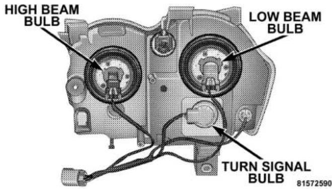
- Disconnect the electrical connector and replace the bulb.
CAUTION!
Donottouchthenewbulbwithyourfingers.Oil contaminationwillseverelyshortenbulblife.Ifthe bulbcomesincontactwithanyoilysurface,clean thebulbwithrubbingalcohol.
FrontFogLight
-
Reach behind the front fascia from under the vehicle.
-
Turn the front fog light bulb 1/4 turn counter clockwise to remove from housing.
-
Disconnect the electrical connector and replace bulb.
344MAINTAININGYOURVEHICLE
CAUTION!
Donottouchthenewbulbwithyourfingers.Oil contaminationwillseverelyshortenbulblife.Ifthe bulbcomesincontactwithanyoilysurface,clean thebulbwithrubbingalcohol.
RearTail, Stop, TurnSignal, and Back-Up Lights
- Raise the liftgate.
- Remove the two Torx fasteners.
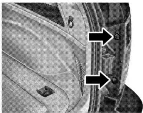
natural_image
Close-up of a car's side profile showing two black arrows pointing to a keyhole or lock mechanism (no text or symbols visible)81572594
- Squeeze the socket assembly tabs to remove it from the housing.

- Pull the bulb to remove it from the socket.
- Replace the bulb, reinstall the socket, and reattach the light assembly.
CenterHighMountedStopLight(CHMSL)
- Remove the two screws securing the CHMSL.
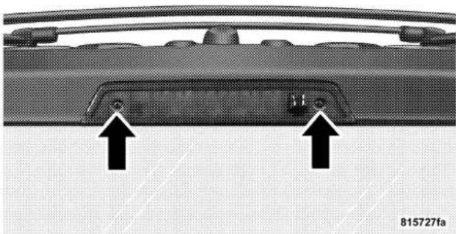
natural_image
Close-up of a car rear panel with two black arrows pointing to a component, no visible text or symbols- Twist the bulb socket to remove from the CHMSL housing.
- Pull the bulb out of the socket.
- Replace the bulb, reinstall the socket and reattach the CHMSL.
346MAINTAININGYOURVEHICLE
FLUIDCAPACITIES
U.S.Metric
| Fuel(Approximate)21 Gallons 79 Liters | ||
| EngineOilwithFilter | ||
| 6.1 Liter Engine (SAE 0W-40, API Certified) 7 Qts 6.6 Liters | ||
| CoolingSystem* | ||
| 6.1 Liter Engine (Mopar®Engine Coolant/Antifreeze 5 Year/100,000 Mile Formula) | 14.8 Qts 14 Liters | |
| * Includes heater and coolant recovery bottle filled to MAX level. | ||
FLUIDS, LUBRICANTS, ANDGENUINEPARTS
Engine
| ComponentFluid,Lubricant,orGenuinePart | |
| Engine Coolant Mopar®Antifreeze/ | Coolant 5 Year/100,000 Mile Formula HOAT (Hybrid Organic Additive Technology) |
| Engine Oil (6.1L Engine) Use API Certified SM/CF synthetic engine oil. SAE 0W-40 is recommended, meeting the requirements of DaimlerChrysler Material Standard MS-10725. | |
| Oil Filter (6.1L Engine) Mopar®Oil Filter (P/N 05281090) or equivalent. | |
| Spark Plugs Refer to the Vehicle Emission Control Information label in the engine compartment. | |
| Fuel Selection (6.1L Engine) Premium | Unleaded 91 Octane Only or higher. |
Chassis
| ComponentFluid,Lubricant,orGenuine | Part |
| Automatic Transmission Mopar® ATF+ | 4 Automatic Transmission Fluid |
| Transfer Case Mopar® NV146 Transfer | Case Fluid or equivalent. Usage of other fluid/lubricants is NOTrecommended. |
| Axle Differential (Front-Rear) | Mopar® Synthetic Gear & Axle Lubricant SAE 75W-140 (API-GL5) or equivalent. |
| Brake Master Cylinder Mopar® DOT 3 | Brake Fluid, SAE J1703 should be used. If DOT 3, SAE J1703 brake fluid is not available, then DOT 4 is acceptable. Use only recommended brake fluids. |
| Power Steering Reservoir This system | requires the use of Mopar® Hydraulic System Power Steering Fluid (P/N 05142893AA) or equivalent, which meets DaimlerChrysler Material Standard MS-10838. |
MAINTENANCESCHEDULES
CONTENTS
■Emission Control System Maintenance....3 5 0 □Schedule "B"....3 5 3
■Maintenance Schedules 350 □Schedule "A" 363
350 MAINTENANCESCHEDULES
The “Scheduled” maintenance services, listed in bold typemust be done at the times or mileages specified to assure the continued proper functioning of the emission control system. These, and all other maintenance services included in this manual, should be done to provide best vehicle performance and reliability. More frequent maintenance may be needed for vehicles in severe operating conditions such as dusty areas and very short trip driving.
Inspection and service also should be done any time a malfunction is suspected.
NOTE: Maintenance, replacement, or repair of the emission control devices and systems on your vehicle may be performed by any automotive repair establishment or individual using any automotive part which has been certified pursuant to U.S. EPA or, in the State of California, California Air Resources Board regulations.
MAINTENANCESCHEDULES
There are two maintenance schedules that show the required service for your vehicle.
First is Schedule "B". It is for vehicles that are operated under the conditions that are listed below and at the beginning of the schedule.
• Day or night temperatures are below 32°F (0°C)
- Stop and go driving
- Excessive engine idling
- Driving in dusty conditions
- Short trips of less than 10 miles (16.2 km)
- More than 50% of your driving is at sustained high speeds during hot weather, above 90°F (32°C)
- Trailer towing
NOTE: Most vehicles are operated under the conditions listed for Schedule "B."
NOTE: If ANY of these apply to you, change your engine oil every 3,000 miles (5 000 km) or 3 months, whichever comes first, and follow the maintenance recommendations in “Maintenance Schedule B.”
NOTE: If ANY of these apply to you then flush and replace your engine coolant every 102,000 miles (170 000 km) or 60 months, whichever comes first, and follow "Schedule B" of the "Maintenance Schedules" section of this manual.
Second is Schedule "A". It is for vehicles that are not operated under any of the conditions listed under Schedule "B."
Use the schedule that best describes your driving conditions. Where time and mileage are listed, follow the interval that occurs first.
CAUTION!
Failuretoperformtherequiredmaintenanceitems mayresultindamagetothevehicle.
At Each Stop for Fuel
- Check the engine oil level about 5 minutes after a fully warmed engine is shut off. Checking the oil level while the vehicle is on level ground will improve the accuracy of the oil level reading. Add oil only when the level is at or below the ADD or MIN mark.
- Check the windshield washer solvent, add as required.
352MAINTENANCESCHEDULES
Once a Month
- Check the tire pressure and look for unusual wear or damage.
- Inspect the battery and clean and tighten the terminals as required.
- Check the fluid levels of the coolant reservoir, brake master cylinder, and add as needed.
- Check all lights and all other electrical items for correct operation.
At Each Oil Change
- Change the engine oil filter.
- Inspect the exhaust system.
- Inspect brake hoses.
- Check the engine coolant/anti-freeze level, hoses, and clamps.
Schedule“B”
Follow this schedule if you usually operate your vehicle under one or more of the following conditions.
• Day or night temperatures are below 32irc F ( 0irc C)
- Stop and go driving
- Excessive engine idling
- Driving in dusty conditions
- Short trips of less than 10 miles (16.2 km)
- More than 50% of your driving is at sustained high speeds during hot weather, above 90°F (32°C)
- Trailer towing
NOTE: If ANY of these apply to you, change your engine oil every 3,000 miles (5 000 km) or 3 months, whichever comes first, and follow the maintenance recommendations in “Maintenance Schedule B.”
NOTE: If ANY of these apply to you then flush and replace your engine coolant every 102,000 miles (170 000 km) or 60 months, whichever comes first, and follow "Schedule B" of the "Maintenance Schedules" section of this manual.
354SCHEDULE“B”
| Miles3,0006,0009,00012,00015,000(Kilometers)(5000)(10000)(15000)(20000)(25000) | |||||
| Change the engine oil and engine oil filter, if not replaced at 3 months. | X | X | X | ||
| Inspecttheengineaircleanerfilter,replaceifnecessary. | X | ||||
| Drain and refill the front and rear axles. X | |||||
| Inspect the brake linings. X |
X
SCHEDULE“B”355
| Miles18,00021,00024,00027,00030,000(Kilometers)(30000)(35000)(40000)(45000)(50000) | |||||
| Change the engine oil and engine oil filter, if not replaced at 3 months. | X | X | X | ||
| Inspecttheengineaircleanerfilter,replaceifnecessary. | X | ||||
| InspectthePCVValve,replaceifnecessary.◇X | |||||
| Drain and refill the front and rear axles. X | |||||
| Inspect the brake linings. X | |||||
| Drain the transfer case and refill. X |
356SCHEDULE“B”
| Miles33,00036,00039,00042,00045,000(Kilometers)(55000)(60000)(65000)(70000)(75000) | |||||
| Change the engine oil and engine oil filter, if not replaced at 3 months. | X | X | X | ||
| Inspecttheengineaircleanerfilter,replaceifnecessary. | X | ||||
| Drain and refill the front and rear axles. X | |||||
| Inspect the brake linings. X |
X
| Miles48,00051,00054,00057,00060,000(Kilometers)(80000)(85000)(90000)(95000)(100000) | |||||
| Change the engine oil and engine oil filter, if not replaced at 3 months. | X | X | X | ||
| Inspecttheengineaircleanerfilter,replaceifnecessary. | X | ||||
| InspectthePCVValve,replaceifnecessary.◇X | |||||
| Inspect drive belt, replace if necessary. X | |||||
| Inspect the brake linings. XX | |||||
| Drain and refill the front and rear axles. | X | ||||
| Drain and refill the transfer case fluid. | X | ||||
| Drain and refill the automatic transmission fluid, and replace filter. | X | ||||
| Flush and replace engine coolant/anti-freeze. | X |
358SCHEDULE“B”
| Miles63,00066,00069,00072,00075,000(Kilometers)(105000)(110000)(115000)(120000)(125000) | |||||
| Change the engine oil and engine oil filter, if not replaced at 3 months. | X | X | X | ||
| Inspecttheengineaircleanerfilter,replaceifnecessary. | X | ||||
| Inspect the drive belt, replace if necessary. X | |||||
| Inspect the brake linings. X | |||||
| Drain and refill the front and rear axle fluid. X |
X
| Miles78,00081,00084,00087,00090,000(Kilometers)(130000)(135000)(140000)(145000)(150000) | |||||
| Change the engine oil and engine oil filter, if not replaced at 3 months. | X | X | X | ||
| Inspecttheengineaircleanerfilter,replaceifnecessary. | X | ||||
| InspectthePCVValve,replaceifnecessary.◇X | |||||
| Inspect the drive belt, replace if necessary.* X | |||||
| Drain and refill the transfer case fluid. X | |||||
| Inspect the brake linings. X | |||||
| Drain and refill the front and rear axle fluid. X |
360 SCHEDULE“B”
| Miles93,00096,00099,000102,000105,000(Kilometers)(155000)(160000)(165000)(170000)(175000) | |||||
| Change the engine oil and engine oil filter, if not replaced at 3 months. | X | X | X | ||
| Inspecttheengineaircleanerfilter,replaceifnecessary. | X | ||||
| Replacethsparkplugs.X | |||||
| Inspect the drive belt, replace if necessary.* X | |||||
| Inspect the brake linings. X | |||||
| Drain and refill the front and rear axle fluid. X | |||||
| Flush and replace the engine coolant/anti-freeze, if not done at 60 months. | X |
X
| Miles108,000111,000114,000117,000120,000(Kilometers)(180000)(185000)(190000)(195000)(200000) | |||||
| Change the engine oil and engine oil filter, if not replaced at 3 months. | X | X | X | ||
| Inspecttheengineaircleanerfilter,replaceifnecessary. | X | ||||
| InspectthePCVValve,replaceifnecessary.◇X | |||||
| Inspect the drive belt, replace if necessary.* X | |||||
| Inspect the brake linings. X X | |||||
| Drain and refill the front and rear axle fluid. X | |||||
| Drain and refill the automatic transmission fluid, and replace filter. | X | ||||
| Drain and refill the transfer case fluid. | X | ||||
| Flush and replace the engine coolant/anti-freeze at 120 months, if not replaced at 102,000 miles (170 000 km). | X |
362SCHEDULE“B”
Inspection and service should also be performed anytime a malfunction is observed or suspected. Retain all receipts.
◇ This maintenance is recommended by the manufacturer to the owner, but is not required to maintain emissions warranty.
* This maintenance is not required if the belt was previously replaced.
SCHEDULE "A" 363
Schedule“A”
| Miles6,00012,00018,00024,00030,000(Kilometers)(10000)(20000)(30000)(40000)(50000)[Months][6][12][18][24][30] | |||||
| Change the engine oil and engine oil filter. X X X X X | |||||
| Inspecttheengineaircleanerfilter,andreplaceif necessary. | X | ||||
| Inspect the brake linings. | X | ||||
| Drain the transfer case and refill. | X |
364 SCHEDULE "A"
| Miles36,00042,00048,00054,000(Kilometers)(60000)(70000)(80000)(90000)[Months][36][42][48][54] | ||||
| Change the engine oil and engine oil filter. X X X X | ||||
| Inspect the brake linings. X X |
SCHEDULE "A" 365
| Miles60,00066,00072,00078,000(Kilometers)(100000)(110000)(120000)(130000)[Months][60][66][72][78] | ||||
| Change the engine oil and engine oil filter. X X X X | ||||
| Inspecttheengineaircleanerfilter,andreplaceifnec-essary. | X | |||
| Inspect the PCV Valve, replace if necessary.◇ | X | |||
| Inspect the drive belt, replace if necessary. | X | |||
| Flush and replace the engine coolant/anti-freeze at 60 months. | X | |||
| Inspect the brake linings. | X | |||
| Drain the transfer case and refill. | X |
366 SCHEDULE "A"
| Miles84,00090,00096,000102,000(Kilometers)(140000)(150000)(160000)(170000)[Months][84][90][96][102] | ||||
| Change the engine oil and engine oil filter. X X X X | ||||
| Inspecttheengineaircleanerfilter,andreplaceifnecessary. | X | |||
| InspectthePCVValve,replaceifnecessary.◇X | ||||
| Replacethsparkplugs. | X | |||
| Inspect the drive belt, replace if necessary.* | X | |||
| Inspect the brake linings. | X | |||
| Flush and replace the engine coolant/anti-freeze if not replaced at 60 months. | X | |||
| Drain the transfer case and refill. | X |
SCHEDULE "A" 367
| Miles108,000114,000120,000(Kilometers)(180000)(190000)(200000)[Months][108][114][120] | |||
| Change the engine oil and engine oil filter. X X X | |||
| Inspecttheengineaircleanerfilter,andreplaceifnecessary.X | |||
| InspectthePCVValve,replaceifnecessary.◇X | |||
| Inspect the drive belt, replace if necessary.* X | |||
| Inspect the brake linings. X | |||
| Flush and replace the engine coolant/anti-freeze if not done at 102,000 miles (170 000 km). | X | ||
| Drain the transfer case and refill. | X |
Inspection and service should also be performed anytime a malfunction is observed or suspected. Retain all receipts.
◇ This maintenance is recommended by the manufacturer to the owner, but is not required to maintain emissions warranty.
* This maintenance is not required if the belt was previously replaced.
368SCHEDULE"A"
WARNING!
Youcanbebadlyinjuredworkingonorarounda motorvehicle.Doonlythatserviceworkforwhich youhavetheproperequipment.Ifyouhaveany doubtaboutyourabilitytoperformaservicejob, takeyourvehicletoacompetentmechanic.
IFYOUNEEDCONSUMERASSISTANCE
CONTENTS
■Suggestions For Obtaining Service For Your Vehicle....370
□Prepare For The Appointment....370
□Prepare A List....370
□Be Reasonable With Requests....370
■If You Need Assistance....370
■Warranty Information (U.S. Vehicles Only) ..... 3 7 3
■Mopar®Parts....373
■ Reporting Safety Defects .....373
□In Canada 373
■ Publication Order Forms .....374
■Department Of Transportation Uniform Tire Quality Grades 375
□Treadwear....375
□Traction Grades....375
□Temperature Grades 37
SUGGESTIONSFOROBTAININGSERVICEFOR YOURVEHICLE
PrepareForTheAppointment
If you're having warranty work done, be sure to have the right papers with you. Take your warranty folder. All work to be performed may not be covered by the warranty, discuss additional charges with the service manager. Keep a maintenance log of your vehicle's service history. This can often provide a clue to the current problem.
PrepareAList
Make a written list of your vehicle's problems or the specific work you want done. If you've had an accident, or work done that is not on your maintenance log, let the service advisor know.
BeReasonableWithRequests
If you list a number of items, and you must have your vehicle by the end of the day, discuss the situation with the service advisor and list the items in order of priority. At many dealers you may obtain a rental vehicle at a minimal daily charge. If you need a rental, it is advisable to make these arrangements when you call for an appointment.
IFYOUNEEDASSISTANCE
The manufacturer and its dealers are vitally interested in your satisfaction. We want you to be happy with our products and services.
Warranty service must be done by an authorized Chrysler, Dodge, or Jeep dealer. We strongly recommend that you take your vehicle to your selling dealer. They know you and your vehicle best, and are most concerned that you get prompt and high quality service. The manufacturer's dealers have the facilities, factory-trained
IFYOUNEEDCONSUMERASSISTANCE371
technicians, special tools, and the latest information to assure your vehicle is fixed correctly and in a timely manner.
This is why you should always talk to your dealer's service manager first. Most matters can be resolved with this process.
- If for some reason you are still not satisfied, talk to the general manager or owner of the dealership. They want to know if you need assistance.
- If your dealership is unable to resolve the concern, you may contact the Manufacturer's Customer Center.
Any communication to the Manufacturer's Customer Center should include the following information:
- Owner's name and address
- Owner's telephone number (home and office)
- Dealership name
• Vehicle identification number
• Vehicle delivery date and mileage
DaimlerChrysler Motors Corporation Customer Center P.O. Box 21-8004
Auburn Hills, MI 48321-8004
Windsor, Ontario N9A 4H6
Phone —(800) 465–2001
In Mexico contact:
In Mexico (915) 729–1248 or 729–1240
Outside Mexico (525) 729–1248 or 729–1240
Customer Assistance For The Hearing Or Speech Impaired (TDD/TTY)
To assist customers who have hearing difficulties, the manufacturer has installed special TDD (Telecommunication Devices for the Deaf) equipment at its Customer Center. Any hearing or speech impaired customer who has access to a TDD or a conventional teletypewriter (TTY) in the United States can communicate with the manufacturer by dialing 1-800-380-CHRY.
Service Contract
You may have purchased a service contract for your vehicle to help protect you from the high cost of unexpected repairs after your manufacturer's new vehicle limited warranty expires. The manufacturer stands behind only the manufacturer's Service Contracts. If you purchased a manufacturer's Service Contract, you will receive Plan Provisions and an Owner Identification Card in the mail within three weeks of your vehicle delivery date. If you have any questions about your service
contract, call the manufacturer's Service Contract National Customer Hotline at 1-800-521-9922.
The manufacturer will not stand behind any service contract that is not the manufacturer's Service Contract. It is not responsible for any service contract other than the manufacturer's Service Contract. If you purchased a service contract that is not a manufacturer's Service Contract, and you require service after your manufacturer's new vehicle limited warranty expires, please refer to your contract documents, and contact the person listed in those documents.
We appreciate that you have made a major investment when you purchased your new vehicle. Your dealer has also made a major investment in facilities, tools, and training to assure that you are absolutely delighted with your ownership experience. You'll be pleased with their sincere efforts to resolve any warranty issues or related concerns.
WARRANTYINFORMATION(U.S.VehiclesOnly)
See the Warranty Information Booklet for the terms and provisions of DaimlerChrysler's warranties applicable to this vehicle.
MOPAR®PARTS
Mopar®fluids, lubricants, parts, and accessories are available from your dealer. They will help you keep your vehicle operating at its best.
REPORTINGSAFETYDEFECTS
In the 50 United States and Washington D.C.: If you believe that your vehicle has a defect, which could cause a crash or cause injury or death, you should immediately inform the National Highway Traffic Safety Administration (NHTSA) in addition to notifying the manufacturer.
If NHTSA receives similar complaints, it may open an investigation, and if it finds that a safety defect exists in a group of vehicles, it may order a recall and remedy campaign. However, NHTSA cannot become involved in individual problems between you, your dealer, and the manufacturer.
To contact NHTSA, you may either call the Auto Safety Hotline toll free at 1-888-327-4236 (TTY: 1-800-424-9153), or go to http://www.NHTSA.gov. or write to: NHTSA, U.S. Dept. of Transportation, Washington DC 20590. You can also obtain other information about motor vehicle safety from the Hotline.
InCanada:
If you believe that your vehicle has a safety defect, you should contact the Customer Service Department immediately. Canadian customers who wish to report a safety defect to the Canadian government should write to Transport Canada, Motor Vehicle Defect Investigations and Recalls, 2780 Sheffield Road, Ottawa, Ontario K1B 3V9.
PUBLICATIONORDERFORMS
To order the following manuals, you may use either the website or the phone numbers listed below. Visa, Mastercard, American Express, and Discover orders are accepted. If you prefer mailing your payment, please call for an order form.
NOTE:A street address is required when ordering manuals. (No P.O. Boxes).
• ServiceManuals.
These comprehensive service manuals provide the information that students and professional technicians need in diagnosing/troubleshooting, problem solving, maintaining, servicing, and repairing DaimlerChrysler Corporation vehicles. A complete working knowledge of the vehicle, system, and/or components is written in straightforward language with illustrations, diagrams, and charts.
• DiagnosticProcedureManuals.
Filled with diagrams, charts and detailed illustrations, these practical manuals make it easy for students and technicians to find and fix problems on computer-controlled vehicle systems and features. They show exactly how to find and correct problems the first time, using step-by-step troubleshooting and driveability procedures, proven diagnostic tests and a complete list of all tools and equipment.
- Owner'sManuals.
These manuals have been prepared with the assistance of service and engineering specialists to acquaint you with specific Chrysler group vehicles. Included are starting, operating, emergency and maintenance procedures as well as specifications, capabilities and safety tips.
Call Toll Free at:
• 1-800-890-4038(U.S.)
• 1-800-387-1143(Canada)
Or
Visit us on the World Wide Web at:
• www.techauthority.daimlerchrysler.com
• www.daimlerchrysler.ca/manuals
DEPARTMENTOFTRANSPORTATIONUNIFORM TIREQUALITYGRADES
The following describes the tire grading categories established by the National highway Traffic Safety Administration. The specific grade rating assigned by the tire's manufacturer in each category is shown on the sidewall of the tires on your car.
All Passenger Car Tires Must Conform to Federal Safety Requirements in Addition to These Grades.
Treadwear
The treadwear grade is a comparative rating based on the wear rate of the tire when tested under controlled conditions on a specified government test course. For example, a tire graded 150 would wear one and a half (1 1/2) times as well on the government course as a tire graded 100. The relative performance of tires depends upon the actual conditions of their use, however, and may depart significantly from the norm due to variations in driving habits, service practices and differences in road characteristics and climate.
TractionGrades
The traction grades, from highest to lowest, are AA, A, B, and C. Those grades represent the tire's ability to stop on wet pavement as measured under controlled conditions
376IFYOUNEEDCONSUMERASSISTANCE
on specified government test surfaces of asphalt and concrete. A tire marked C may have poor traction performance.
WARNING!
Thetractiongradeassignedtothistireisbasedon straight-aheadbrakingtractiontests, and does not include acceleration, cornering, hydroplaning, or peaktraction characteristics.
TemperatureGrades
The temperature grades are A (the highest), B, and C, representing the tire's resistance to the generation of heat and its ability to dissipate heat when tested under controlled conditions on a specified indoor laboratory test wheel. Sustained high temperature can cause the material of the tire to degenerate and reduce tire life, and excessive temperature can lead to sudden tire failure. The
grade C corresponds to a level of performance which all passenger car tires must meet under the Federal Motor Vehicle Safety Standard No. 109. Grades B and A represent higher levels of performance on the laboratory test wheel than the minimum required by law.
WARNING!
Thetemperaturegradeforthistireisestablished for atirethatisproperlyinflatedandnotoverloaded. Excessivespeed,underinflation,orexcessiveloading,eitherseparatelyorincombination,cancause heatbuildupandpossibletirefailure.
INDEX
ABS (Anti-Lock Brake System)....173,245
Adding Engine Coolant (Antifreeze) ..... 3 2 0
Adding Fuel 274
Adding Washer Fluid 165
Additives, Fuel 272
Adjustable Pedals....1 2 6
Air Conditioner Maintenance....3 1 3
Air Conditioning, Operating Tips ..... 2 2 8
Air Conditioning Refrigerant....3 1 4
Air Pressure, Tires 260
Airbag 43
Airbag Deployment 50
Airbag Light....52,66,173
Airbag Maintenance....5 1
Alarm (Security Alarm) 18,174
Alarm System (Security Alarm)....18
Alignment and Balance 266
Alterations/Modifications, Vehicle 9
Antenna, Satellite Radio 218
Antifreeze (Engine Coolant) 319,346
Disposal....3 2 1
Anti-Lock Brake System (ABS)....131,245
Anti-Lock Warning Light 173
Anti-Theft System....18,174
Appearance Care 329
Auto Down Power Windows....30
Automatic Dimming Mirror ..... 7 4
Automatic Door Locks 27
Automatic Headlights 115
Automatic Temperature Control (ATC) ..... 222
Automatic Transmission 239,327,328
Adding Fluid 328
Fluid and Filter Changes 328
Fluid Change 328
Fluid Level Check 327
Autostick 241
Auxiliary Electrical Outlet (Power Outlet) ..... 1 5 5
Auxiliary Power Outlet 155
INDEX 379
Battery 312
Emergency Starting 293
Keyless Transmitter Replacement (RKE) ..... 2 3
Saving Feature (Protection)....1 1 4
Bearings 329
Belts, Drive 309
Belts, Seat 3 5
Body Mechanism Lubrication....3 1 6
B-Pillar Location 254
Brake Assist System 132
Brake Control System, Electronic . . . . . . . . . . . 1 3 1
Brake System 324
Anti-Lock (ABS)....131,245
Fluid Check 325
Hoses 324
Parking 244
Warning Light 172
Brake/Transmission Interlock 238
Break-In Recommendations, New Vehicle ..... 64
Bulb Replacement 340,341
Camera, Rear 143
Capacities, Fluid 346
Caps, Filler Fuel .... 2 7 4 Radiator (Coolant Pressure).... 3 2 1
Car Washes 330
Carbon Monoxide Warning 65,146,273
Cargo Area Cover 159
Cargo Area Features....158
Cargo Compartment 158 Light 158
Cargo Light 158
Cargo Load Floor 163
Cargo Tie-Downs....161
Catalytic Converter....3 1 0
Caution, Exhaust Gas 146
CD (Compact Disc) Player ..... 1 9 5
Cellular Phone 78
Center High Mounted Stop Light 345
Chart, Tire Sizing....251
Checks, Safety 66,67
Child Restraint 54,60,62
Child Restraint Tether Anchors ..... 58,60
Child Safety Locks 28
Clean Air Gasoline 271
Climate Control 2 2 2
Clock....197,210
Compact Disc (CD) Maintenance ..... 2 2 1
Compass 186
Compass Variance....193
Computer, Trip/Travel 186
Console, Overhead 144
Contract, Service 372
Coolant Pressure Cap (Radiator Cap) ..... 3 2 1
Cooling System 318
Adding Coolant (Antifreeze)....320
Coolant Capacity 346
Coolant Level 318,322
Disposal of Used Coolant 321
Drain, Flush, and Refill 319
Inspection 322
Points to Remember....322
Pressure Cap 321
Radiator Cap 321
Selection of Coolant (Antifreeze) ..... 319,346
Cruise Control (Speed Control) 128
Cruise Light 177
Cup Holder 157
Customer Assistance 370
Data Recorder, Event 52
Daytime Running Lights 117
Dealer Service 304
Defroster, Rear Window 165
Defroster, Windshield ..... 66,226
INDEX381
Diagnostic System, Onboard 301
Dimmer Switch, Headlight ..... 1 1 9
Dipsticks Power Steering....3 1 4
Disposal Antifreeze (Engine Coolant) 3 2 1
Door Locks 26
Door Locks, Automatic ..... 2 7
Door Opener, Garage ..... 1 4 5
Drive Belts 309
DVD Player (Video Entertainment System) ..... 2 1 4
Electric Remote Mirrors 76
Electrical Outlet, Auxiliary (Power Outlet) ..... 1 5 5
Electronic Brake Control System ..... 1 3 1
Electronic Speed Control (Cruise Control) ..... 1 2 8
Electronic Stability Program (ESP) ..... 1 3 4
Electronic Throttle Control Warning Light ..... 1 7 8
Electronic Vehicle Information Center (EVIC) . 176,179
Emergency, In Case of
Freeing Vehicle When Stuck 241
Hazard Warning Flasher 292
Jump Starting 293
Emission Control System Maintenance ..... 302,350
Engine
Air Cleaner 310
Air Cleaner Filter 310
Break-In Recommendations....64
Checking Oil Level 305
Compartment 300
Compartment Identification....300
Coolant (Antifreeze) 3 1 8
Cooling 318
Exhaust Gas Caution 65,273
Fails to Start 235
Flooded, Starting 235
Fuel Requirements 270,346
Oil 305,346
Oil Change Interval....306
Oil Selection 307,346
Overheating 293
Starting 234
Temperature Gauge 175
Engine Oil Viscosity 308
Engine Oil Viscosity Chart....308
Enhanced Accident Response Feature ..... 5 1
Entry System, Illuminated ..... 1 9
Event Data Recorder....52
Exhaust Gas Caution....65,273,318
Exhaust System 317
Exterior Finish Care 330
Filters
Air Cleaner....3 1 0
Engine Fuel 310
Engine Oil 308
Engine Oil Disposal 308
Finish Care 330
Flashers 292
Hazard Warning 292
Turn Signal 172,342,344
Flipper Glass, Liftgate 3 3
Flooded Engine Starting 235
Fluid Capacities 346
Fluid Leaks 67
Fluid Level Checks
Brake 325
Cooling System 318
Engine Oil 305
Power Steering 314
Fluids, Lubricants and Genuine Parts ..... 3 4 7
Fog Light Service 343
Fog Lights 118,178,343
Folding Rear Seat 105
Four-Way Hazard Flasher 292
Freeing A Stuck Vehicle....241
INDEX383
Fuel 270
Additives 272
Clean Air 271
Filler Cap (Gas Cap) 274
Filter 310
Gasoline 270
Gauge....177
Hoses 327
Requirements 270,346
Tank Capacity 346
Fuel System Caution 275,276
Fuses 333
Garage Door Opener (HomeLink®) 145
Gas Cap (Fuel Filler Cap)....274,276,302
Gasoline, Clean Air 271
Gasoline (Fuel) 270
Gasoline, Reformulated 271
Gauges
Coolant Temperature 175
Fuel 177
Speedometer 172
Tachometer 174
Gear Ranges 239
General Information 23,270
Glass Cleaning 332
Gross Axle Weight Rating 278
Gross Vehicle Weight Rating 277
Hands-Free Phone (UConnect™) 78
Hazard Warning Flasher 292
Head Restraints 103
Head Rests 103
Headlights 115
Bulb Replacement 341
On With Wipers 115
Replacing 341
Heated Mirrors 77
Heated Seats 103
High Beam Indicator 172
High Beam/Low Beam Select (Dimmer) Switch .. 119
Hitches Trailer Towing....281
Holder, Cup 157
HomeLink®(Garage Door Opener) Transmitter . . . 145
Hood Release....1 1 2
Hoses....323,327
Ignition Key 1
Illuminated Entry 19
Infant Restraint 54
Inflation Pressure Tires 260
Information Center, Vehicle 179
Instrument Cluster....171,172
Instrument Panel and Controls ..... 1 7 0
Instrument Panel Lens Cleaning 332
Integrated Power Module (Fuses) ..... 3 3 8
Interior Appearance Care....3 3 1
Interior Fuses....3 3 3
Interior Lighting 119
Interior Lights 1 17,119
Intermittent Wipers (Delay Wipers) 1 2 2
Introduction 4
Jump Starting 293
Key, Programming 17
Key, Replacement....17
Key, Sentry (Immobilizer) 15
Key-In Reminder 15
Keyless Entry System 19
Keys 14
Lap/Shoulder Belts 35
INDEX385
LATCH
(Lower Anchors and Tether for CHildren) . . . . . 58,60
Lead Free Gasoline 270
Leaks, Fluid 67
Life of Tires 264
Liftgate 32
Liftgate Flipper Glass 3 3
Liftgate Window Wiper/Washer....164
Lights....67,114
Airbag 52,173
Alarm 6 6
Anti-Lock 173
Automatic Headlights 1 1 5
Back-Up 344
Battery Saver 114
Brake Assist Warning ..... 136,176
Brake Warning....172
Bulb Replacement 341
Cargo 158
Center Mounted Stop 345
Cruise 177
Daytime Running 117
Dimmer Switch, Headlight ..... 1 14,119
Electronic Stability Program (ESP)
Indicator 136,174,176
Electronic Throttle Control Warning 178
Fog 1 18,178,343
Fuses 3 3 3
Hazard Warning Flasher 292
Headlight Switch 115
Headlights 341
Headlights On With Wipers....1 1 5
High Beam Indicator 172
Illuminated Entry 19
Instrument Cluster....1 15,117
Interior 17,119
Lights On Reminder 118
Low Fuel....178
386INDEX
Low Tire 17Lpad Floor, Cargo 163
Malfunction Indicator (Check Engine) ..... 1 7 2
Map Reading 120
Oil Pressure....174
Passing....1 1 9
Reading....120,145
Rear Servicing....344
Rear Tail 344
Seat Belt Reminder....177
Security Alarm (Theft Alarm)....174
Service 341
Service Engine Soon (Malfunction Indicator) . . . 172
Side Marker 344
SmartBeams 116
Tire Pressure Monitoring (TPMS) ..... 1 7 5
Traction Control 136,174
Turn Signal 114,118,342,344
Vanity Mirror 77
Voltage 178
Loading Vehicle Tires 254
Locks 26
Automatic Door 27
Child Protection 28
Door 26
Power Door 26
Lower Anchors and Tether for CHildren
(LATCH) 58,60
Lubrication, Body 316
Lumbar Support 102
Maintenance Free Battery 312
Maintenance Procedures 305
Maintenance Schedule 350
Schedule "A" 363
Schedule "B" 353
Maintenance Schedules 350
INDEX 387
Malfunction Indicator Light (Check Engine) .. 172,302
Manual, Service 374
Memory Feature (Memory Seat)....107
Memory Seat 107
Memory Seats and Radio 107
Mini-Trip Computer 188
Mirrors 74
Automatic Dimming 74
Electric Powered....76
Electric Remote 76
Exterior Folding....7 5
Heated 77
Outside 75
Vanity 77
Modifications/Alterations, Vehicle 9
Monitor, Tire Pressure System 266
Mopar Parts 304,373
Multi-Function Control Lever 1 1 4
Navigation Radio 209
Navigation System 209
New Vehicle Break-In Period 64
Occupant Restraints 34
Odometer....176,177
Tr i p 176
Oil, Engine 305
Capacity 346
Change Interval 306
Checking 305
Disposal 308
Filter 308
Filter Disposal 308
Materials Added to 308
Pressure Warning Light....174
Recommendation 307,346
Viscosity 346
Onboard Diagnostic System....301,302
388INDEX
Opener, Garage Door (HomeLink®) 145
Outside Rearview Mirrors 75
Overhead Console 144
Overheating, Engine . . . . . . . . . . . . . . . . . . . . . 176,293
Owner's Manual (Operator Manual) ..... 3 7 4
Paint Care 329
Paint Damage 329
Panic Alarm 2 2
Park Assist System, Rear 137
Parking Brake 244
Passing Light 119
Pedals, Adjustable....1 2 6
Pets 64
Pets, Transporting 64
Phone, Cellular 78
Phone, Hands-Free (UConnect™) 7 8
Placard, Tire and Loading Information ..... 2 5 4
Polishing and Waxing 3 3 0
Power
Distribution Center (Fuses) 3 3 6
Door Locks 26
Mirrors....76
Outlet (Auxiliary Electrical Outlet) ..... 1 5 5
Seats 102,103
Steering 248,314
Sunroof 152
Windows 29
Pregnant Women and Seat Belts 42
Pretensioners
Seat Belts 41
Programmable Electronic Features ..... 147,151,181
Programming Transmitters
(Remote Keyless Entry)....147,151
Radial Ply Tires 262
Radiator Cap (Coolant Pressure Cap) 3 2 1
Radio Broadcast Signals ..... 1 9 4
INDEX 389
Radio, Navigation....209
Radio Operation....195,221
Radio, Satellite 210,216
Radio (Sound Systems) 195
Rain Sensitive Wiper System....1 2 3
Rear Camera 143
Rear Cup Holder....157
Rear Park Assist System 137
Rear Seat, Folding....105
Rear Window Defroster....165
Rear Window Features 164
Rear Wiper/Washer 164
Reclining Front Seats 101
Recorder, Event Data 52
Recreational Towing 289
Refrigerant....314
Reminder, Lights On....11 8
Remote Keyless Entry (RKE) 19
Remote Sound System (Radio) Controls ..... 2 1 9
Remote Starting System 24
Replacement Bulbs 340
Replacement Tires 265
Reporting Safety Defects 373
Restraints, Child 54
Restraints, Occupant 34
Retractable Cargo Area Cover ..... 1 5 9
Rocking Vehicle When Stuck 241
Rotation, Tires 266
Safety Checks Inside Vehicle 6 6
Safety Checks Outside Vehicle....67
Safety Defects, Reporting 373
Safety Information, Tire 250
Safety Tips 65
Satellite Radio 210,216
Satellite Radio Antenna 218
Schedule, Maintenance 350
Seat Belt Maintenance....6 6
Seat Belts 35
Adjustable Upper Shoulder Anchorage ..... 4 0
And Pregnant Women....4 2
Child Restraint 54,62
Extender 42
Front Seat 35
Inspection 6 6
Maintenance 66,333
Pretensioners 41
Reminder 177
Shoulder Belt Anchorage 40
Seats 100
Adjustment....100
Cleaning 331
Easy Entry 111
Head Restraints 103
Heated....103
Lumbar Support....102
Memory 107
Power....102,103
Rear Folding 105
Reclining 101
Security Alarm (Theft Alarm) 18,174
Selection of Coolant (Antifreeze) 319
Selection of Oil 307
Sentry Key (Immobilizer) 15
Sentry Key Programming 17
Sentry Key Replacement 17
Service Assistance....370
Service Contract 372
Service Engine Soon Light (Malfunction Indicator) . 172
Service Manuals 374
Setting the Clock.... 197,210
Shifting 238
Automatic Transmission 238
Shoulder Belts 35
Signals, Turn 118,172,342,344
SmartBeams 11 6
INDEX391
Spark Plugs....309
Speed Control (Cruise Control) 1 2 8
Speedometer 172
Starting 234
Automatic Transmission....234
Cold Weather 235
Engine Fails to Start 235
Remote 24
Steering
Power 248,314
Wheel, Tilt 125
Steering Wheel Mounted Sound System Controls . 219
Storage 339
Storage, Behind the Seat . . . . . . . . . . . . . . . . . . . . . . 1 5 9
Storage Bin 159
Storage Compartment, Center Seat ..... 1 0 7
Storage, Vehicle ..... 229,339
Storing Your Vehicle 339
Sun Roof 152
Sunglasses Storage 145
Supplemental Restraint System - Airbag ..... 43
System, Navigation 209
System, Remote Starting 24
Tachometer 174
Temperature Control, Automatic (ATC) ..... 222
Temperature Gauge, Engine Coolant ..... 175
Tether Anchor, Child Restraint 58
Tie Down Hooks, Cargo ..... 1 6 1
Tilt Steering Column 125
Time Delay, Headlight 119
Tire and Loading Information Placard ..... 254
Tire Identification Number (TIN) 253
Tire Markings 250
Tire Safety Information 250
Tires 67,258,375
Air Pressure 26 0
Alignment and Balance 266
General Information 258
High Speed....261
Inflation Pressures 260
Life of Tires 264
Load Capacity 254,255
Pressure Monitor System (TPMS)....266
Pressure Warning Light....175
Quality Grading 375
Radial 262
Replacement 265
Rotation....266
Safety 67,250
Sizes 251
Spinning 263
Tread Wear Indicators 263
Tongue Weight/Trailer Weight 282
Towing 277
Behind a Motor Home 289
Guide 282
Recreational 289
Weight 282
Towing Vehicle Behind a Motor Home ..... 2 8 9
Traction Control 132
Traction Control Light 174
Trailer Towing 277
Cooling System Tips 289
Hitches 281
Minimum Requirements 284
Trailer and Tongue Weight 282
Wiring 287
Trailer Towing Guide 282
Trailer Weight 282
Transmission 327
Automatic 239,327
Range Indicator 177
Shifting 238
Transmitter Battery Service (Remote Keyless Entry) . 23
Transmitter, Garage Door Opener (HomeLink®) .. 145
INDEX 393
Transmitter, Remote Keyless Entry (RKE) ..... 1 9
Tread Wear Indicators 263
Turn Signals....1 18,172,342,344
UConnect™ (Hands-Free Phone) 78
Underhood Fuses....336,338
Uniform Tire Quality Grades ..... 3 7 5
Universal Transmitter 145
Unleaded Gasoline 270
Upholstery Care....3 3 1
Vanity Mirrors 77
Variance, Compass ..... 1 9 3
Vehicle Identification Number (VIN) 8
Vehicle Loading 255
Vehicle Modifications/Alterations 9
Vehicle Storage 229,339
Video Entertainment System
(Rear Seat Video System)....2 1 4
Viscosity, Engine Oil 308
Warning Flasher, Hazard 292
Warnings and Cautions 8
Warranty Information 373
Washer, Adding Fluid 165
Washers, Windshield ..... 121,316
Washing Vehicle 330
Waxing and Polishing 3 3 0
Wheel Alignment and Balance 266
Wheel and Wheel Trim 3 3 1
Wheel and Wheel Trim Care 3 3 1
Wheel Bearings 329
Wind Buffeting 32,154
Window Fogging....2 2 8
Windows....29
Power 29
Windshield Defroster 66,226
Windshield Washers 12
394INDEX
Fluid 316
Windshield Wiper Blades 3 1 6
Windshield Wipers....1 2 1
Wiper Blade Replacement....3 1 6
Wipers, Intermittent ..... 1 2 2
Wipers, Rain Sensitive....1 2 3
NOTES
NOTES
NOTES
NOTES
NOTES
NOTES



- 4INTRODUCTION
- INTRODUCTION
- RollOverWarning
- RollOverWarningLabel
- 6INTRODUCTION
- WARNING!
- HOWTOUSETHISMANUAL
- 8INTRODUCTION
- WARNINGSANDCAUTIONS
- VEHICLEIDENTIFICATIONNUMBER
- VEHICLEMODIFICATIONS/ALTERATIONS
- THINGSTOKNOWBEFORESTARTINGYOURVEHICLE
- CONTENTS
- THINGSTOKNOWBEFORESTARTINGYOURVEHICLE
- THINGSTOKNOWBEFORESTARTINGYOURVEHICLE13
- IgnitionKeyRemoval
- Key-In-IgnitionReminder
- SENTRYKEYIMMOBILIZERSYSTEM
- NOTE:
- ImportantNoteAboutService
- ReplacementKeys
- CustomerKeyProgramming
- GeneralInformation
- SECURITYALARMSYSTEM—IFEQUIPPED
- ToSettheAlarm
- THINGSTOKNOWBEFORESTARTINGYOURVEHICLE19
- ToDisarmtheSystem
- ILLUMINATEDENTRY
- REMOTEKEYLESSENTRY
- 20THINGSTOKNOWBEFORESTARTINGYOURVEHICLE
- ToUnlocktheDoors
- THINGSTOKNOWBEFORESTARTINGYOURVEHICLE21
- ToLocktheDoors
- ToReleasetheLiftgateFlipperGlass
- UsingThePanicAlarm
- ToTurnOff"FlashLightsOnLock/Unlock"
- THINGSTOKNOWBEFORESTARTINGYOURVEHICLE23
- TransmitterBatteryService
- REMOTESTARTINGSYSTEM—IFEQUIPPED
- THINGSTOKNOWBEFORESTARTINGYOURVEHICLE25
- DOORLOCKS
- ManualDoorLocks
- PowerDoorLocks—IfEquipped
- THINGSTOKNOWBEFORESTARTINGYOURVEHICLE27
- AutomaticDoorLocks
- AutomaticUnlockonExitFeature—Only Available if AutoLockisEnabled
- THINGSTOKNOWBEFORESTARTINGYOURVEHICLE29
- WINDOWS
- PowerWindows
- AutoUpFeaturewithAnti-PinchProtection (Driver'sandFrontPassengerDoorOnly)
- THINGSTOKNOWBEFORESTARTINGYOURVEHICLE31
- ResettingtheAuto-UpFeature
- WindowLockoutSwitch
- LIFTGATE
- THINGSTOKNOWBEFORESTARTINGYOURVEHICLE33
- LiftgateFlipperGlass
- OCCUPANTRESTRAINTS
- THINGSTOKNOWBEFORESTARTINGYOURVEHICLE35
- Lap/ShoulderBelts
- Lap/ShoulderBeltOperatingInstructions
- THINGSTOKNOWBEFORESTARTINGYOURVEHICLE37
- THINGSTOKNOWBEFORESTARTINGYOURVEHICLE39
- AdjustableUpperShoulderBeltAnchorage
- AutomaticLockingMode—IfEquipped
- WhenToUseTheAutomaticLockingMode
- HowToUseTheAutomaticLockingMode
- HowtoDisengageTheAutomaticLockingMode
- EnergyManagementFeature
- SeatBeltPretensioners
- THINGSTOKNOWBEFORESTARTINGYOURVEHICLE
- SeatBeltsandPregnantWomen
- SeatBeltExtender
- THINGSTOKNOWBEFORESTARTINGYOURVEHICLE43
- WindowAirbagLocation
- AirbagSystemComponents
- THINGSTOKNOWBEFORESTARTINGYOURVEHICLE49
- IfADeploymentOccurs
- EnhancedAccidentResponseFeature
- EventDataRecorder(EDR)
- ChildRestraint
- InfantsandChildRestraints
- THINGS TO KNOW BEFORE STARTING YOUR VEHICLE
- OlderChildrenandChildRestraints
- ChildrenTooLargeforBoosterSeats
- LATCH—ChildSeatAnchorageSystem(Lower AnchorsandTetherforChildren)
- THINGSTOKNOWBEFORESTARTINGYOURVEHICLE59
- InstallingtheLATCH-CompatibleChildRestraint System
- TetherStrapMounting
- 62THINGSTOKNOWBEFORESTARTINGYOURVEHICLE
- InstallingChildRestraintsUsingtheVehicleSeat Belt
- THINGSTOKNOWBEFORESTARTINGYOURVEHICLE63
- TransportingPets
- ENGINEBREAK-INRECOMMENDATIONS
- SAFETYTIPS
- ExhaustGas
- THINGSTOKNOWBEFORESTARTINGYOURVEHICLE65
- AirbagWarningLight
- Defrosters
- THINGSTOKNOWBEFORESTARTINGYOURVEHICLE67
- SafetyChecksYouShouldMakeOutsideThe Vehicle
- Tires
- Lights
- FluidLeaks
- UNDERSTANDINGTHEFEATURESOFYOURVEHICLE
- 70UNDERSTANDINGTHEFEATURESOFYOURVEHICLE
- UNDERSTANDINGTHEFEATURESOFYOURVEHICLE 71
- UNDERSTANDINGTHEFEATURESOFYOURVEHICLE
- UNDERSTANDINGTHEFEATURESOFYOURVEHICLE73
- 74UNDERSTANDINGTHEFEATURESOFYOURVEHICLE
- MIRRORS
- AutomaticDimmingMirror
- CAUTION!
- OutsideMirrors
- ExteriorMirrorsFoldingFeature
- 76UNDERSTANDINGTHEFEATURESOFYOURVEHICLE
- Driver's Outside Automatic Dimming Mirror—If Equipped
- PowerRemoteControlOutsideMirrors
- UNDERSTANDINGTHEFEATURESOFYOURVEHICLE77
- HeatedRemoteControlMirrors—IfEquipped
- LightedVanityMirrors—IfEquipped
- HANDS-FREECOMMUNICATION(UConnect™)—IFEQUIPPED
- UNDERSTANDINGTHEFEATURESOFYOURVEHICLE79
- UConnect™Switches
- Operations
- 80UNDERSTANDINGTHEFEATURESOFYOURVEHICLE
- VoiceCommandTree
- HelpCommand
- CancelCommand
- UNDERSTANDINGTHEFEATURESOFYOURVEHICLE81
- Pair(Link)UConnect™SystemtoaCellularPhone
- 82UNDERSTANDINGTHEFEATURESOFYOURVEHICLE
- Call/DialbySayingaNumber
- Call/DialbySayingaName
- AddNamestoYourUConnect™Phonebook
- 84UNDERSTANDINGTHEFEATURESOFYOURVEHICLE
- EditEntriesintheUConnect™Phonebook
- DeleteEntriesintheUConnect™Phonebook
- UNDERSTANDINGTHEFEATURESOFYOURVEHICLE85
- DeleteAllEntriesintheUConnect™Phonebook
- ListAllNamesintheUConnect™Phonebook
- 86UNDERSTANDINGTHEFEATURESOFYOURVEHICLE
- PhoneCallFeatures
- AnswerorRejectanIncomingCall-NoCall CurrentlyinProgress
- AnswerorRejectanIncomingCall-Call CurrentlyinProgress
- UNDERSTANDINGTHEFEATURESOFYOURVEHICLE87
- Making a Second Call while Current Call in Progress
- Place/RetrieveaCallfromHold
- TogglingBetweenCalls
- ConferenceCall
- Three-WayCalling
- 88UNDERSTANDINGTHEFEATURESOFYOURVEHICLE
- CallTermination
- Redial
- CallContinuation
- UConnect™SystemFeatures
- LanguageSelection
- UNDERSTANDINGTHEFEATURESOFYOURVEHICLE89
- Emergency Assistance
- 90UNDERSTANDINGTHEFEATURESOFYOURVEHICLE
- Towing Assistance
- Paging
- VoiceMailCalling
- WorkingwithAutomatedSystems
- BargeIn-OverridingPrompts
- TurningConfirmationPromptsOn/Off
- PhoneandNetworkStatusIndicators
- DialingUsingtheCellularPhoneKeypad
- Mute/Un-mute(Muteoff)
- InformationService
- AdvancedPhoneConnectivity
- TransferCalltoandfromCellularPhone
- ConnectorDisconnectLinkBetweenthe UConnect™SystemandCellularPhone
- ListPairedCellularPhoneNames
- 94UNDERSTANDINGTHEFEATURESOFYOURVEHICLE
- SelectanotherCellularPhone
- DeleteUConnect™PairedCellularPhones
- ThingsYouShouldKnowAboutYourUConnect™ System
- VoiceRecognition(VR)
- UNDERSTANDINGTHEFEATURESOFYOURVEHICLE95
- 96UNDERSTANDINGTHEFEATURESOFYOURVEHICLE
- FarEndAudioPerformance
- BluetoothCommunicationLink
- Power-Up
- UNDERSTANDINGTHEFEATURESOFYOURVEHICLE97
- 98UNDERSTANDINGTHEFEATURESOFYOURVEHICLE
- UNDERSTANDINGTHEFEATURESOFYOURVEHICLE99
- North American English
- SEATS
- FrontManualSeatAdjustment
- FrontSeatAdjustment—Recline
- 102UNDERSTANDINGTHEFEATURESOFYOURVEHICLE
- ManualLumbarSupportAdjustment
- 8-WayDriver'sPowerSeat
- 4-WayPassenger'sPowerSeat—IfEquipped
- HeadRestraints
- HeatedSeats—IfEquipped
- 104UNDERSTANDINGTHEFEATURESOFYOURVEHICLE
- UNDERSTANDINGTHEFEATURESOFYOURVEHICLE105
- 60/40SplitRearSeat
- To Lower Rear Seat
- 106UNDERSTANDINGTHEFEATURESOFYOURVEHICLE
- To Raise Rear Seat
- UNDERSTANDINGTHEFEATURESOFYOURVEHICLE107
- Storage—RearSeatArmrest(IfEquipped)
- DRIVERMEMORYSEAT—IFEQUIPPED
- SettingMemoryPositionsandLinkingRemote KeylessEntryTransmittertoMemory
- MemoryPositionRecall
- 110UNDERSTANDINGTHEFEATURESOFYOURVEHICLE
- ToDisableATransmitterLinkedtoMemory
- EasyEntry/ExitSeat
- UNDERSTANDINGTHEFEATURESOFYOURVEHICLE111
- 112UNDERSTANDINGTHEFEATURESOFYOURVEHICLE
- TOOPENANDCLOSETHEHOOD
- UNDERSTANDINGTHEFEATURESOFYOURVEHICLE113
- 114UNDERSTANDINGTHEFEATURESOFYOURVEHICLE
- Multi-FunctionControlLever
- BatterySaverFeature—Exterior/InteriorLights
- UNDERSTANDINGTHEFEATURESOFYOURVEHICLE115
- HeadlightsandParkingLights
- AutomaticHeadlightSystem—IfEquipped
- HeadlightsOnAutomaticallyWithWipers
- SmartBeams—IfEquipped
- ToActivate
- ToDeactivate
- InstrumentPanelandInteriorLights
- DaytimeRunningLights—IfEquipped
- Lights-OnReminder
- FogLights—IfEquipped
- The fog light switch is located in the multifunction control lever. To activate the fog lights, turn on the park/turn lights, low beam headlights, or "Auto" headlights and pull out the end of the multifunction control lever. A light in the instrument cluster shows when the fog lights are on.
- TurnSignals
- TurnSignalAuto-Mode
- UNDERSTANDINGTHEFEATURESOFYOURVEHICLE119
- HighBeamSwitch
- PassingLight
- HeadlightTimeDelay
- InteriorLights
- 120UNDERSTANDINGTHEFEATURESOFYOURVEHICLE
- FrontMap/ReadingLights
- UNDERSTANDINGTHEFEATURESOFYOURVEHICLE121
- 122UNDERSTANDINGTHEFEATURESOFYOURVEHICLE
- Mist
- SpeedSensitiveIntermittentWiperSystem
- UNDERSTANDINGTHEFEATURESOFYOURVEHICLE123
- RainSensingWipers—IfEquipped
- 124UNDERSTANDINGTHEFEATURESOFYOURVEHICLE
- UNDERSTANDINGTHEFEATURESOFYOURVEHICLE125
- TILTSTEERINGCOLUMN
- 126UNDERSTANDINGTHEFEATURESOFYOURVEHICLE
- ADJUSTABLEPEDALS—IFEQUIPPED
- UNDERSTANDINGTHEFEATURESOFYOURVEHICLE127
- 128UNDERSTANDINGTHEFEATURESOFYOURVEHICLE
- ELECTRONICSPEEDCONTROL
- ToSetataDesiredSpeed
- ToResumeSpeed
- ToVarytheSpeedSetting
- ToAccelerateforPassing
- 130UNDERSTANDINGTHEFEATURESOFYOURVEHICLE
- DrivingUporDownHills
- ELECTRONICBRAKECONTROLSYSTEM
- ABS(Anti-LockBrakeSystem)
- TCS(TractionControlSystem)
- BAS(BrakeAssistSystem)
- ERM(ElectronicRollMitigation)
- 134UNDERSTANDINGTHEFEATURESOFYOURVEHICLE
- ESP(ElectronicStabilityProgram)
- On
- Partial Off
- 136UNDERSTANDINGTHEFEATURESOFYOURVEHICLE
- ESP/BASWarningLampandESP/TCSIndicator Light
- ESP BAS
- REARPARKASSISTSYSTEM—IFEQUIPPED
- 138UNDERSTANDINGTHEFEATURESOFYOURVEHICLE
- RearParkAssistSensors
- RearParkAssistWarningDisplay
- UNDERSTANDINGTHEFEATURESOFYOURVEHICLE139
- 140UNDERSTANDINGTHEFEATURESOFYOURVEHICLE
- Enable/DisabletheRearParkAssistSystem
- ServicetheRearParkAssistSystem
- CleaningtheRearParkAssistSystem
- REARCAMERA—IFEQUIPPED
- TurningtheRearCameraOn
- 144UNDERSTANDINGTHEFEATURESOFYOURVEHICLE
- TurningtheRearCameraOff
- OVERHEADCONSOLE
- UNDERSTANDINGTHEFEATURESOFYOURVEHICLE145
- Courtesy/ReadingLights
- SunglassesStorage
- GARAGEDOOROPENER
- 146UNDERSTANDINGTHEFEATURESOFYOURVEHICLE
- UNDERSTANDINGTHEFEATURESOFYOURVEHICLE147
- ProgrammingHomeLink
- 148UNDERSTANDINGTHEFEATURESOFYOURVEHICLE
- 150UNDERSTANDINGTHEFEATURESOFYOURVEHICLE
- CanadianProgramming/GateProgramming
- UsingHomeLink
- UNDERSTANDINGTHEFEATURESOFYOURVEHICLE151
- ErasingHomeLinkButtons
- ReprogrammingaSingleHomeLinkButton
- Security
- 152UNDERSTANDINGTHEFEATURESOFYOURVEHICLE
- POWERSUNROOF—IFEQUIPPED
- OpeningSunroof-Express
- ClosingSunroof-Express
- PinchProtectFeature
- 154UNDERSTANDINGTHEFEATURESOFYOURVEHICLE
- PinchProtectOverride
- VentingSunroof-Express
- SunshadeOperation
- WindBuffeting
- UNDERSTANDINGTHEFEATURESOFYOURVEHICLE155
- SunroofMaintenance
- IgnitionOffOperation
- SunroofFullyClosed
- POWEROUTLET
- 156UNDERSTANDINGTHEFEATURESOFYOURVEHICLE
- ElectricalOutletUseWithEngineOff
- CUPHOLDERS
- 158UNDERSTANDINGTHEFEATURESOFYOURVEHICLE
- CARGOAREAFEATURES
- CargoLight
- UNDERSTANDINGTHEFEATURESOFYOURVEHICLE159
- RearStorageCompartment
- RetractableCargoAreaCover
- 160UNDERSTANDINGTHEFEATURESOFYOURVEHICLE
- UNDERSTANDINGTHEFEATURESOFYOURVEHICLE161
- CargoTie-DownHooks
- 162UNDERSTANDINGTHEFEATURESOFYOURVEHICLE
- UNDERSTANDINGTHEFEATURESOFYOURVEHICLE163
- CargoLoadFloor
- NOTE: The cargoloadfloorlatchess should not be used as cargotie - downs.
- 164UNDERSTANDINGTHEFEATURESOFYOURVEHICLE
- REARWINDOWFEATURES
- RearWindowWiper/Washer—IfEquipped
- UNDERSTANDINGTHEFEATURESOFYOURVEHICLE165
- AddingWasherFluid
- RearWindowDefroster—IfEquipped
- UNDERSTANDING YOUR INSTRUMENT PANEL
- UNDERSTANDING YOUR INSTRUMENT PANEL 169
- 170UNDERSTANDINGYOURINSTRUMENTPANEL
- INSTRUMENTPANELANDCONTROLS
- INSTRUMENTCLUSTER
- 172UNDERSTANDINGYOURINSTRUMENTPANEL
- INSTRUMENTCLUSTERDESCRIPTION
- Speedometer
- Brake Warning Light
- Turn Signal Indicator Light
- High Beam Indicator Light
- Malfunction Indicator Light
- Airbag Warning Light
- Anti-Lock Brake Warning Light
- Tachometer
- Security Alarm System Indicator Light — If Equipped
- Oil Pressure Warning Light
- Electronic Stability Program (ESP) Indicator Light/Traction Control System (TCS) Indicator Light
- Tire Pressure Monitoring Telltale Light
- Temperature Gauge
- Seat Belt Reminder Light
- Cruise Indicator Light
- Odometer
- Transmission Range Indicator
- Fuel Gauge
- 178UNDERSTANDING YOUR INSTRUMENTPANEL
- Electronic Throttle Control (ETC) Warning Light
- Front Fog Light Indicator Light—If Equipped
- Voltage Warning Light
- Low Fuel Warning Light
- UNDERSTANDING YOUR INSTRUMENT PANEL 179
- 180UNDERSTANDINGYOURINSTRUMENTPANEL
- UNDERSTANDING YOUR INSTRUMENT PANEL 181
- CustomerProgrammableFeatures
- 182UNDERSTANDINGYOURINSTRUMENTPANEL
- Language?
- DisplayU.S.orMetric?
- AutoDoorLocks?
- AutoUnlockOnExit?(AvailableOnlyWhenthe AUTODOORLOCKSFeatureisTurnedOn)
- RemoteUnlockDriver'sDoor1st?
- RemoteLinkedToMemory?(Availablewith MemorySeatOnly)
- SoundHornWithLock?
- FlashLightsWithLock?
- 184UNDERSTANDING YOUR INSTRUMENT PANEL
- HeadlampDelay
- IlluminatedApproach?
- AutoHeadlampLow/HighBeams?(Availablewith SmartBeamOnly)
- HeadlampsOnWithWipers?(AvailablewithAuto HeadlightsOnly)
- FrontWipersRainSense?(AvailablewithRain SensingWipersOnly)
- ServiceInterval
- ResetServiceDistance(DisplaysWithIfService IntervalwasChanged)
- EasyEntry/ExitSeat?(AvailablewithMemorySeat Only)
- 186UNDERSTANDINGYOURINSTRUMENTPANEL
- Compass/Temperature/TripComputer
- 188UNDERSTANDINGYOURINSTRUMENTPANEL
- TripComputer
- StepButton
- UNDERSTANDING YOUR INSTRUMENT PANEL 189
- ResetButton
- AverageFuelEconomy
- DistanceToEmpty
- TripA
- TripB
- 190UNDERSTANDINGYOURINSTRUMENTPANEL
- ElapsedTime
- EngineOilPressure
- EngineOilTemperature
- TirePressureDisplay
- MilestoneService
- BlankScreen
- ManualCompassCalibration
- 192UNDERSTANDINGYOURINSTRUMENTPANEL
- ToPutIntoaCalibrationMode
- UNDERSTANDING YOUR INSTRUMENT PANEL 193
- 194UNDERSTANDINGYOURINSTRUMENTPANEL
- RADIOGENERALINFORMATION
- RadioBroadcastSignals
- TwoTypesofSignals
- ElectricalDisturbances
- AMReception
- FMReception
- SALESCODERAQ-AM/FM/CD(6-DISC)RADIO WITHOPTIONALSATELLITERADIO,HANDS FREEPHONE,ANDVEHICLEENTERTAINMENT SYSTEMS(VES)CAPABILITIES
- OperatingInstructions-RadioMode
- 196UNDERSTANDING YOUR INSTRUMENTPANEL
- PowerSwitch/VolumeControl(Rotary)
- ElectronicVolumeControl
- modeButton(RadioMode)
- SEEKButton(RadioMode)
- MUTEButton(RadioMode)
- SCANButton(RadioMode)
- MSGorINFOButton(RadioMode)
- TimeButton
- ClockSettingProcedure
- RW/FF(RadioMode)
- TUNEControl(RadioMode)
- 198UNDERSTANDINGYOURINSTRUMENTPANEL
- AM/FMButton(RadioMode)
- SettingtheTone,Balance,andFade
- RND/PTYButton(RadioMode)
- SET/DIRButton(RadioMode)—ToSetthe Push-ButtonMemory
- Buttons 1 - 6 (RadioMode)
- OperationInstructions-(CDMODEforCDAudio Play)
- InsertingCompactDisc(s)
- 202UNDERSTANDINGYOURINSTRUMENTPANEL
- SEEKButton(CDMODEforCDAudioPlay)
- MUTEButton(CDMODEforCDAudioPlay)
- SCANButton(CDMODEforCDAudioPlay)
- LOAD/EJECTButton(CDModeforCDAudio Play)
- LOAD/EJECT-Load
- LOAD/EJT-Eject
- TIMEButton(CDMODEforCDAudioPlay)
- RW/FF(CDMODEforCDAudioPlay)
- TUNEControl(CDMODEforCDAudioPlay)
- AM/FMButton(CDMODEforCDAudioPlay)
- 204UNDERSTANDINGYOURINSTRUMENTPANEL
- RND/PTYButton(RandomPlayButton)(CD MODEforCDAudioPlay)
- Buttons 1 - 6 ( C D MODEforCDAudioPlay)
- NotesOnPlayingMP3Files
- SupportedMedia(DiscTypes)
- SupportedMediumFormats(FileSystems)
- SupportedMP3FileFormats
- PlaybackofMP3Files
- OperationInstructions-(CDModeforMP3Audio Play)
- SEEKButton(CDModeforMP3Play)
- LOAD/EJECTButton(CDModeforMP3Play)
- LOAD/EJECT-Eject
- 208UNDERSTANDINGYOURINSTRUMENTPANEL
- MSGorINFOButton(CDModeforMP3Play)
- RW/FF(CDModeforMP3Play)
- TUNEControl(CDModeforMP3Play)
- AM/FMButton(CDModeforMP3Play)
- RND/PTYButton(CDModeforMP3Play)
- SET/DIRButton(CDModeforMP3Play)
- Buttons 1 - 6 ( C D ModeforMP3Play)
- OperatingInstructions-HandsFreePhone(If Equipped)
- OperatingInstructions-SatelliteRadioMode(If Equipped)
- OperatingInstructions-VideoEntertainment System(VES®)(IfEquipped)
- SALESCODEREC—AM/FM/CD(6-DISC)RADIO WITHNAVIGATIONSYSTEM
- UNDERSTANDING YOUR INSTRUMENT PANEL
- OperatingInstructions—SatelliteRadio(If Equipped)
- RECSettingtheClock
- GPSClock
- UNDERSTANDING YOUR INSTRUMENT PANEL 211
- UserDefinedClock
- 212UNDERSTANDING YOUR INSTRUMENTPANEL
- AudioClockDisplay
- 214UNDERSTANDINGYOURINSTRUMENTPANEL
- VIDEOENTERTAINMENTSYSTEM(SALESCODE XRV)—IFEQUIPPED
- UNDERSTANDING YOUR INSTRUMENT PANEL 215
- SystemActivation
- ElectronicSerialNumber/SiriusIdentification Number(ESN/SID)
- ESN/SIDAccesswithRECRadios
- ESN/SIDAccesswithRAQRadios
- SelectingSatelliteModeinRAQRadios
- SelectingaChannel
- UNDERSTANDING YOUR INSTRUMENT PANEL
- StoringandSelectingPre-SetChannels
- UsingthePTY(ProgramType)Button—If Equipped
- PTYButton"SCAN"
- PTYButton"SEEK"
- SatelliteAntenna
- ReceptionQuality
- REMOTESOUNDSYSTEMCONTROLS
- 220UNDERSTANDINGYOURINSTRUMENTPANEL
- RadioOperation
- CDPlayer
- CD/DVDDISCMAINTENANCE
- RADIOOPERATIONANDCELLULARPHONES
- CLIMATECONTROLS
- AutomaticTemperatureControl
- 224UNDERSTANDINGYOURINSTRUMENTPANEL
- ManualOperation
- - Defrost
- - Defrost/Floor
- - Floor
- - Bi-Level
- - Panel
- 228UNDERSTANDINGYOURINSTRUMENTPANEL
- OperatingTips
- WindowFogging
- SummerOperation
- WinterOperation
- VacationStorage
- NormalStarting
- ExtremeColdWeather(below-20°F(-29°C)
- IfEngineFailstoStart
- AfterStarting
- AUTOMATICTRANSMISSION
- Brake/TransmissionInterlockSystem
- 5-SpeedAutomaticTransmission
- GearRanges
- R(Reverse)
- N(Neutral)
- D(Drive)
- RockingtheVehicle
- AUTOSTICK
- AutostickOperation
- AutostickGeneralInformation
- ANTI-LOCKBRAKESYSTEM
- POWERSTEERING
- TIRESAFETYINFORMATION
- TireldentificationNumber(TIN)
- TireandLoadingInformationPlacard
- TireandLoadingInformation
- Loading
- Steps for Determining Correct Load Limit
- TIRES—GENERALINFORMATION
- RunFlatTires
- TirePressure
- Safety—
- Economy—
- Ride Comfort and Vehicle Stability—
- TirePressuresforHighSpeedOperation
- Radial-PlyTires
- TireSpinning
- TreadWearIndicators
- LifeofTire
- ReplacementTires
- AlignmentandBalance
- TIREPRESSUREMONITORSYSTEM(TPMS)
- PremiumSystem
- LEFTFRONT, LEFTREAR, RIGHTFRONT, RIGHTREARLOWPRESSURE
- CHECKTPMSYSTEM
- FUELREQUIREMENTS
- Reformulated Gasoline
- Gasoline/OxygenateBlends
- MMTInGasoline
- MaterialsAddedtoFuel
- FuelSystemCautions
- CarbonMonoxideWarnings
- ADDINGFUEL
- FuelFillerCap(GasCap)
- LooseFuelFillerCapMessage
- TRAILERTOWING
- CommonTowingDefinitions
- GrossVehicleWeightRating(GVWR)
- GrossTrailerWeight(GTW)
- GrossCombinationWeightRating(GCWR)
- GrossAxleWeightRating(GAWR)
- TongueWeight(TW)
- FrontalArea
- TrailerSwayControl
- Weight-CarryingHitch
- Weight-DistributingHitch
- TrailerHitchClassification
- TrailerTowingWeights(MaximumTrailerWeightRatings)
- TrailerandTongueWeight
- TowingRequirements—Tires
- TowingRequirements—TrailerBrakes
- TowingRequirements—TrailerLights&Wiring
- TowingTips—AutomaticTransmission
- TowingTips—ElectronicSpeedControl(If Equipped)
- TowingTips—CoolingSystem
- - City Driving
- - Highway Driving
- RECREATIONAL TOWING(BEHIND MOTORHOME, ETC.)
- WHATODOINEMERGENCIES
- 292WHATODOINEMERGENCIES
- IFYOURENGINEOVERHEATS
- JUMPSTARTING
- MAINTAINING YOUR VEHICLE
- 298MAINTAININGYOURVEHICLE
- MAINTAINING YOUR VEHICLE299
- ONBOARDDIAGNOSTICSYSTEM—OBDII
- EMISSIONSINSPECTIONANDMAINTENANCE PROGRAMS
- REPLACEMENTPARTS
- DEALERSERVICE
- MAINTENANCEPROCEDURES
- EngineOil
- CheckingOilLevel
- 306MAINTAININGYOURVEHICLE
- ChangeEngineOil
- EngineOilSelection
- 308MAINTAININGYOURVEHICLE
- EngineOilViscosityChart
- MaterialsAddedtoEngineOil
- Disposing of Used Engine Oil And Oil Filters
- EngineOilFilter
- EngineOilFilterSelection
- DriveBelts—CheckConditionandTensioner
- SparkPlugs
- 310MAINTAININGYOURVEHICLE
- EngineAirCleanerFilter
- FuelFilter
- CatalyticConverter
- Maintenance-FreeBattery
- AirConditionerMaintenance
- Refrigerant Recovery and Recycling
- PowerSteeringFluidCheck
- 316MAINTAININGYOURVEHICLE
- BodyLubrication
- WindshieldWiperBlades
- WindshieldWashers—FrontandRear
- ExhaustSystem
- CoolingSystem
- CoolantChecks
- CoolingSystem—Drain, Flushand Refill
- SelectionOfCoolant
- AddingCoolant
- CoolingSystemPressureCap
- DisposalofUsedEngineCoolant
- 322MAINTAINING YOUR VEHICLE
- CoolantLevel
- PointsToRemember
- HosesAndVacuum/VaporHarnesses
- 324MAINTAININGYOURVEHICLE
- BrakeSystem
- BrakeAndPowerSteeringHoses
- BrakeFluidLevelCheck
- 326MAINTAININGYOURVEHICLE
- FuelSystemHoses
- FluidLevelCheck
- FluidandFilterChanges
- FrontAndRearWheelBearings
- AppearanceCareAndProtectionFromCorrosion
- ProtectionofBodyandPaintfromCorrosion
- WhatCausesCorrosion?
- 330MAINTAININGYOURVEHICLE
- Washing
- SpecialCare
- MAINTAININGYOURVEHICLE331
- WheelandWheelTrimCare
- InteriorCare
- LeatherSeatCare&Cleaning
- 332MAINTAININGYOURVEHICLE
- GlassSurfaces
- CleaningPlasticInstrumentClusterLenses
- SeatBeltMaintenance
- FUSEPANEL
- InteriorFuses
- 336MAINTAININGYOURVEHICLE
- 338MAINTAININGYOURVEHICLE
- VEHICLESTORAGE
- REPLACEMENTBULBS
- InteriorLightsBulbType
- ExteriorLightsBulbType
- MAINTAININGYOURVEHICLE341
- BULBREPLACEMENT
- HeadLight
- 342MAINTAININGYOURVEHICLE
- FrontTurnSignal
- FrontFogLight
- 344MAINTAININGYOURVEHICLE
- RearTail, Stop, TurnSignal, and Back-Up Lights
- CenterHighMountedStopLight(CHMSL)
- 346MAINTAININGYOURVEHICLE
- FLUIDS, LUBRICANTS, ANDGENUINEPARTS
- MAINTENANCESCHEDULES
- MAINTENANCESCHEDULES
- At Each Stop for Fuel
- 352MAINTENANCESCHEDULES
- Once a Month
- At Each Oil Change
- Schedule“B”
- 362SCHEDULE“B”
- IFYOUNEEDCONSUMERASSISTANCE
- SUGGESTIONSFOROBTAININGSERVICEFOR YOURVEHICLE
- PrepareForTheAppointment
- PrepareAList
- BeReasonableWithRequests
- IFYOUNEEDASSISTANCE
- IFYOUNEEDCONSUMERASSISTANCE371
- Customer Assistance For The Hearing Or Speech Impaired (TDD/TTY)
- Service Contract
- WARRANTYINFORMATION(U.S.VehiclesOnly)
- MOPAR®PARTS
- REPORTINGSAFETYDEFECTS
- InCanada:
- PUBLICATIONORDERFORMS
- DEPARTMENTOFTRANSPORTATIONUNIFORM TIREQUALITYGRADES
- Treadwear
- TractionGrades
- 376IFYOUNEEDCONSUMERASSISTANCE
- TemperatureGrades
- INDEX
- INDEX 379
- INDEX381
- Filters
- INDEX383
- Gauges
- INDEX385
- LATCH
- 386INDEX
- INDEX 387
- 388INDEX
- Power
- Pretensioners
- INDEX 389
- INDEX391
- INDEX 393
- 394INDEX
- NOTES
Brand : JEEP
Model : Grand Cherokee SRT (2007)
Category : Automobile