
DSA-250 - Receiver DAP-Audio - Free user manual and instructions
Find the device manual for free DSA-250 DAP-Audio in PDF.


| Type | Audio receiver / stereo amplifier |
| Brand | DAP-Audio |
| Model | DSA-250 |
| Dimensions (W x H x D) | Approx. 430 x 88 x 280 mm (rack mountable 2U) |
| Weight | Approx. 6.5 kg |
| Power Output | 2 x 250 W RMS (8 ohms), 2 x 400 W RMS (4 ohms) |
| Frequency Response | 20 Hz – 20 kHz (±1 dB) |
| Input Impedance | 10 kΩ (balanced), 47 kΩ (unbalanced) |
| Signal-to-Noise Ratio | > 100 dB |
| Total Harmonic Distortion | < 0.05% (1 kHz, 8 ohms) |
| Inputs | 2 x XLR/TRS combo, 2 x RCA stereo, 1 x AUX 3.5mm |
| Outputs | 2 x speakON, 2 x binding posts, 1 x XLR line out |
| Amplifier Class | Class AB |
| Protection Features | Short circuit, thermal overload, DC offset, overcurrent |
| Cooling | Variable speed fan, forced air from front to back |
| Power Supply | 230 V AC, 50/60 Hz (switchable to 115 V) |
| Power Consumption | Max 800 W |
| Standby Power | < 0.5 W (if applicable) |
| Chassis Material | Steel, black painted |
| Operating Temperature | 0°C to 40°C |
| Accessories Included | Power cord, user manual, rack ears |
| Recommended Use | PA systems, live sound, installation |
| Certifications | CE, RoHS |
Frequently Asked Questions - DSA-250 DAP-Audio
User questions about DSA-250 DAP-Audio
0 question about this device. Answer the ones you know or ask your own.
Ask a new question about this device
Download the instructions for your Receiver in PDF format for free! Find your manual DSA-250 - DAP-Audio and take your electronic device back in hand. On this page are published all the documents necessary for the use of your device. DSA-250 by DAP-Audio.
USER MANUAL DSA-250 DAP-Audio
You have bought a great, innovative product from DAP Audio.
The DAP Audio DSA series bring excitement to any venue. Whether you want simple plug-&-play action or a sophisticated show, this product provides the effect you need.
You can rely on DAP Audio, for more excellent audio products.
We design and manufacture professional audio equipment for the entertainment industry.
New products are being launched regularly. We work hard to keep you, our customer, satisfied.
You can get some of the best quality, best priced products on the market from DAP Audio.
So next time, turn to DAP Audio for more great audio equipment.
Always get the best -- with DAP Audio!
Thank you!

DAP Audio DSA-250, DSA-400, DSA-600, DSA-800, DSA-1000 Product Guide
Warning 2
Unpacking instructions....2
Safety-instructions 2
Operating determinations....3
Return procedure....3
Claims....4
Description....5
Features 5
Overview front panel 6
Overview back panel 7
Operation....8
Connection cables 9
Maintenance 11
Troubleshooting 12
Product specifications 13
Wire Gauge Charts....14
WARNING
FOR YOUR OWN SAFETY, PLEASE READ THIS USER MANUAL CAREFULLY BEFORE YOUR INITIAL START-UP!
Unpacking Instructions
Immediately upon receiving this product, carefully unpack the carton and check the contents to ensure that all parts are present, and have been received in good condition. Notify the dealer immediately and retain packing material for inspection if any parts appear damaged from shipping or the carton itself shows signs of mishandling. Save the carton and all packing materials. In the event that a fixture must be returned to the factory, it is important that the fixture be returned in the original factory box and packing.
Your shipment includes:
• DAP DSA-amplifier
- IEC cable
- User manual
SAFETY INSTRUCTIONS
Every person involved with the installation, operation and maintenance of this system have to:
- be qualified
- follow the instructions of this manual
CAUTION! Be careful with your operations. With a dangerous voltage you can suffer a dangerous electric shock when touching the wires!
Before you initial start-up, please make sure that there is no damage caused by transportation. Should there be any, consult your dealer and do not use the system.
To maintain perfect condition and to ensure a safe operation, it is absolutely necessary for the user to follow the safety instructions and warning notes written in this manual.
Please consider that damages caused by manual modifications to the system are not subject to warranty.
This system contains no user-serviceable parts. Refer servicing to qualified technicians only.
IMPORTANT:
The manufacturer will not accept liability for any resulting damages caused by the non-observance of this manual or any unauthorized modification to the system.
- Never let the power-cord come into contact with other cables! Handle the power-cord and all connections with the mains with particular caution!
- Never remove warning or informative labels from the unit.
- Never use anything to cover the ground contact.
- Do not insert objects into air vents.
- Do not connect this system to a dimmerpack.
- Do not switch the system on and off in short intervals, as this would reduce the system's life.
- Do not open the device and do not modify the device.
- Do not open this device. Risk: hazardous radiation exposure.
- Only use system indoor, avoid contact with water or other liquids.
- Avoid flames and do not put close to flammable liquids or gases.
- Always disconnect power from the mains, when system is not used. Only handle the power-cord by the plug. Never pull out the plug by tugging the power-cord.
- Make sure you don't use the wrong kind of cables or defective cables.
• Make sure that the signals into the mixer are balanced, otherwise hum could be created.
• Make sure you use DI boxes to balance unbalanced signals; All incoming signals should be clear.
• Make sure that the available voltage is not higher than stated on the rear panel.
- Make sure that the power-cord is never crimped or damaged. Check the system and the power-cord from time to time.
- Make sure that the amplifier is turned down, before turning the power on or off. So you can avoid supersonic frequencies, which could damage your speakers.
- Don't put your equipment next to TV, radio, etc., because of interference or distortion.
• If you connect other parts of the system, be careful of ground loops.
- The best way to avoid ground loops is connecting the electrical system ground to one central point ("star" system). In this case the mixer can act as a central point.
- Before changing the ground, always turn off your amplifier.
- Please read this manual carefully and keep it for future reference. Remember that the amplifier has a better value on the market, if you save the carton and all packing materials.
• Always operate the unit with the AC ground wire connected to the electrical system ground.
- Connecting amplifier outputs to oscilloscopes or other test equipment, while the amplifier is in bridged mode, may damage both the amplifier and test equipment.
- Do not drive the inputs with a signal level bigger, than required to drive the equipment to full output.
- In system setup, the amplifier's output power must be 50%-100% more than the loaded loudspeakers rated power.
- Please turn off the power switch, when changing the power cord or signal cable, or select the input mode switch.
- In typical use, please set the volume at 0dB position.
- Sometimes, when you want to send one signal to more than one amplifier, you should use a signal distributor.
- If your Dap Audio device fails to work properly, discontinue use immediately. Pack the unit securely (preferably in the original packing material), and return it to your Dap Audio dealer for service.
- Allow time to cool down, before cleaning or servicing.
- For replacement use fuses of same type and rating only.
- Prevent distortion! Make sure that all components connected to the DSA have sufficient power ratings. Otherwise distortion will be generated because the components are operated at their limits.
- Avoid ground loops! Always be sure to connect the power amps and the mixing console to the same electrical circuit to ensure the same phase!
- If system is dropped or struck, disconnect mains power supply immediately. Have a qualified engineer inspect for safety before operating.
- If the system has been exposed to drastic temperature fluctuation (e.g. after transportation), do not switch it on immediately. The arising condensation water might damage your system. Leave the system switched off until it has reached room temperature.
- This device falls under protection class I. Therefore it is essential to connect the yellow/green conductor to earth.
• Repairs, servicing and electric connection must be carried out by a qualified technician.
- WARRANTY: Till one year after date of purchase.
OPERATING DETERMINATIONS
If this system is operated in any other way, than the one described in this manual, the product may suffer damages and the warranty becomes void.
Any other operation may lead to dangers like short-circuit, burns, electric shock, etc.
You endanger your own safety and the safety of others!
Improper installation can cause serious damage to people and property!
⚠️ Return Procedure ⚠️
Returned merchandise must be sent prepaid and in the original packing, call tags will not be issued. Package must be clearly labeled with a Return Authorization Number (RMA number). Products returned without an RMA number will be refused. Highlite will not accept the returned goods or any responsibility. Call Highlite 0031-455667723 or mail aftersales@highlite.nl and request an RMA prior to shipping the fixture. Be prepared to provide the model number, serial number and a brief description of the cause for the return. Be sure to properly pack fixture, any shipping damage resulting from inadequate packaging is the customer's responsibility. Highlite reserves the right to use its own discretion to repair or replace product(s). As a suggestion, proper UPS packing or double-boxing is always a safe method to use.
Note: If you are given an RMA number, please include the following information on a piece of paper inside the box:
1) Your name
2) Your address
3) Your phone number
4) A brief description of the symptoms
Claims
The client has the obligation to check the delivered goods immediately upon delivery for any shortcomings and/or visible defects, or perform this check after our announcement that the goods are at their disposal. Damage incurred in shipping is the responsibility of the shipper; therefore the damage must be reported to the carrier upon receipt of merchandise.
It is the customer's responsibility to notify and submit claims with the shipper in the event that a fixture is damaged due to shipping. Transportation damage has to be reported to us within one day after receipt of the delivery.
Any return shipment has to be made post-paid at all times. Return shipments must be accompanied with a letter defining the reason for return shipment. Non-prepaid return shipments will be refused, unless otherwise agreed in writing.
Complaints against us must be made known in writing or by fax within 10 working days after receipt of the invoice. After this period complaints will not be handled anymore.
Complaints will only then be considered if the client has so far complied with all parts of the agreement, regardless of the agreement of which the obligation is resulting.
Description of the device
Features
The DSA-250, DSA-400, DSA-600, DSA-800 and DSA-1000 are professional high-end amplifiers:
- Power rating
DSA-250: RMS 2 X 325W (2Ω), RMS 2 X 250W (4Ω), RMS 2 X 160W (8Ω)
DSA-400: RMS 2 X 355W (2Ω), RMS 2 X 400W (4Ω), RMS 2 X 260W (8Ω)
DSA-600: RMS 2 X 625W (2Ω), RMS 2 X 500W (4Ω), RMS 2 X 330W (8Ω)
DSA-800: RMS 2 X 800W (2Ω), RMS 2 X 625W (4Ω), RMS 2 X 420W (8Ω)
DSA-1000: RMS 2 X 1000W (2Ω), RMS 2 X 800W (4Ω), RMS 2 X 500W (8Ω)
- Features: Clip limiting
Thermal protection
Short circuit protection
DC voltage protection
Subsonic protection
- Class H design except DSA-250 which is a class B design.
• Frequency response: 35Hz\~20KHz
• Sensitivity 8 Ohm stereo 1KHz: 1V
• S/N Ratio: >106 dB
• Damping Factor: >350
• Total Harmonic distortion (THD): <0,1% - Mode: Stereo/ Bridge
• Cooling: multi speed fan
• Airflow: From front to rear - Input/ link connectors: XLR
• Output connectors: Speakon
Dimensions: 88mm x 482mm x 335mm (HxWxD)
Power supply: 230V/50Hz-60Hz
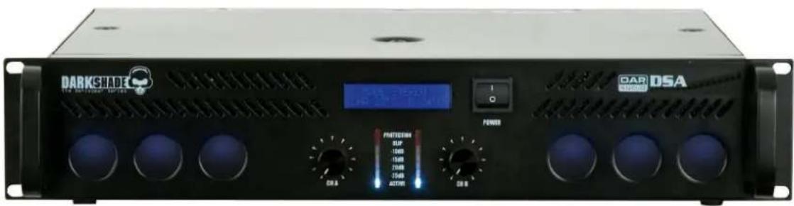
Fig. 1
Frontpanel
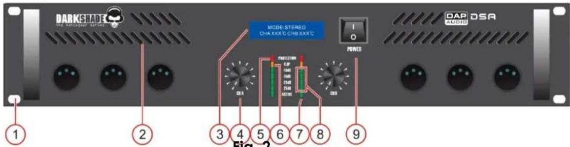
Fig. 2
1. Rack Mounting Holes.
Two front panel mounting holes are provided on each mounting flange,
2. Fan Inlet Grills.
DSA Series amplifiers are cooled by two, rear-mounted fans, Cool air flows over the heat sinks and exhausts through the rear grills. Make sure these outlets remain clear to allow unrestricted air flow,
3. LCD display
Shows the working mode, protection status and temperature of the modules.etc,
4. Input Attenuators.
Whenever possible, set attenuators fully clockwise to maintain optimum system headroom. The input attenuator controls (one for channel A, one for channel B) located at the front panel adjust gain for their respective amplifier channels in all modes. See the specifications at the end of this manual for standard voltage gain and input sensitivity information.
5. Protect LEDs.
Indicates that the channel is in Protect mode (speakers disconnected by output relay),
6. Clip LEDs.
Illuminates at the clipping threshold, Continuous illumination also indicates that ACL (Active Clip Limiting) protection circuitry is engaged.
7. Active LEDs.
Indicates that the channel is active.
8. Level Indicator.
9. AC Power Switch
This is the main Power switch. Press to turn the amplifier on.
Backpanel
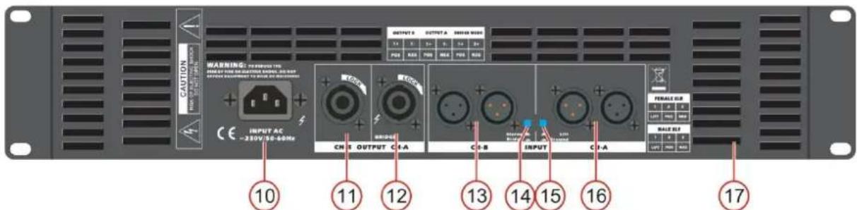
Fig. 3
10. AC Inlet.
This connector is meant for the connection of the supplied main cord. Connect one end of the power cord to the connector, the other end to the mains, then turn on the power switch (9) to operate the unit.
Note: Please make sure that the supply voltage matches the operation voltage before connecting the unit to mains.
11. Output B Speakon Connector.
Using speakon-type speaker cables, make connections to both the channel A and channel B connectors for Stereo or Parallel mode, to channel A connector for Bridged mono mode.
12. Output A Speakon Connector.
Using speakon-type speaker cables, make connections to both the channel A and channel B connectors for Stereo or Parallel mode, to channel A connector for Bridged mono mode.
13. Channel B In/Through Connectors
Using speakon-type speaker cables, make connections to both the channel A and channel B connectors for Stereo or Parallel mode, to channel A connector for Bridged mono mode.
14. Stereo/ Bridge Switch.
The two-position, Mode Select switch (located on the rear panel) configures the amplifier for either Stereo or Bridged Mono Mode.
15. GND Switch.
To eliminate ground loops, put the switch in "OFF" position.
16. Channel A In/Through Connectors
Using speakon-type speaker cables, make connections to both the channel A and channel B connectors for Stereo or Parallel mode, to channel A connector for Bridged mono mode.
17. Air cooling windows
This part is the air cooling window. Don't obstruct it.
Operation
Installation
Remove all packing materials from the DSA. Check that all foam and plastic padding is removed.
Secure the equipment into a 19" rack. Connect all cables.
Connecting Power / Circuit Size Requirements.
DSA Series amplifier power requirements are rated at:
a)"idle"
b) 1/8th power ("typical" music conditions)
c) 1/3rd power ("continuous" music conditions)
d.] maximum rated power (circuit breaker limited).
The maximum power current draw rating is limited only by the front panel circuit breaker. Consult the specification In the Appendices section for figures on the current that each amplifier will demand.
Make sure the mains voltage is correct and is the same as that printed on the rear of the amplifier.
Damage caused by connecting the amplifier to Improper AC voltage is not covered by any warranty.
Unless otherwise specified when ordered. DAP audio amplifiers shipped to customers are configured as follows:
North America 120VAC/60Hz
Europe 230VAC/50Hz
Asia 220VAC /50Hz/60Hz
Australia 240VAC/50Hz
South America 120VAC/60Hz or 220VAC/50Hz
Japan 1OOVAC/50Hz
NOTE: Always turn off and disconnect the amplifier from mains voltage before making audio connections.
Also, as an extra precaution, have the attenuators turned down during power-up.
Cooling System and Requirements.
DSA Series amplifiers use a twin-tunnel forced-air cooling system to maintain a low, even operating temperature. Drawn In by dual fans on the front panel, air flows through the cooling fans of the channel heat sinks (dissipating power transistor heat), then exhausts through the rear panel slots.
IMPORTANT: To ensure optimum cooling, periodically clean the amplifier fan filters (removable without tools). Also make certain that there is enough space around the front of the amplifier to allow the cooling air to escape. If the amplifier is rack-mounted, do not use doors or covers on the front of the rack; the exhaust air must flow out without resistance. If the amplifiers are housed in racks with closed backs, allow at least one (1) standard rack space of opening In the front of the rack for every four amplifiers.
Connecting Inputs.
Use the XLR input connectors on the rear to supply audio signals to your DAP Audio DSA Series amplifier. The connectors accept balanced and unbalanced audio connections. (The TAS Series amplifiers are configured standard with "Pin 2 hot" on XLR inputs. The Link connector can be used to loop the audio Input to another amplifier Input. For more Information, see the section on Connection cables page 10.
Connecting Outputs.
Speakers are connected using Speakon connectors. For examples see figures 4, 5 and 6.
Mode Selection
The stereo/bridge (14) switch (located on the rear panel) allows you to configure the amplifier for either Stereo operation or Bridged Mono operation. Amplifiers are factory-configured for Stereo operation. If you want to use the amplifier in parallel mode, you have to connect the link output of channel A with the input of channel B and make sure that the stereo/bridge (14) switch is not pushed in (stereo mode).
Stereo Mode
In Stereo mode, both channels operate independently, with their input attenuators controlling their respective levels. Signal at Channel A's input produces output at Channel A's output while signal at Channel B's input produces output at Channel B's output. Make sure, the mono/stereo (14) switch is not pushed in (stereo mode).
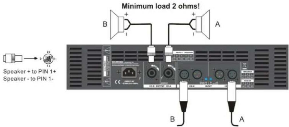
Fig. 4
Important !!!
Absolute minimum nominal load Impedance for stereo operation is 2 Ohm per channel.
Parallel Mode
In parallel Mode, a signal applied to Channel A's input will be amplified and appear at outputs of both Channels A and B. Make sure the mono/stereo (14) switch is not pushed in (stereo mode).
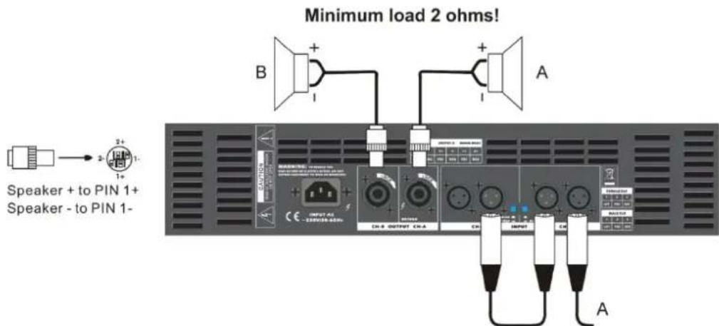
Fig. 5
Important !!!
Absolute minimum nominal load Impedance for parallel operation is 2 Ohm per channel.
Bridged Mono Mode
Bridged Mono Mode straps both amplifier channels together to make a very powerful, single-channel monaural amplifier. One channel "pushes" and the other "pulls" equally, doubling the power over that of channel alone. Signal is applied to the Channel A input only. Both attenuators are used to control signal level; in addition, both must be adjusted to the same setting. Only channel A input may be used. Make sure, the mono/stereo (14) switch is pushed in (bridge mode).
Use extreme caution when operating the amplifier In Bridged Mono Mode. Never ground either side of the speaker cable when the amplifier is in Bridged Mono Mode; both sides are "hot." If an output patch panel is used, all connections must be Isolated from each other and from the panel.
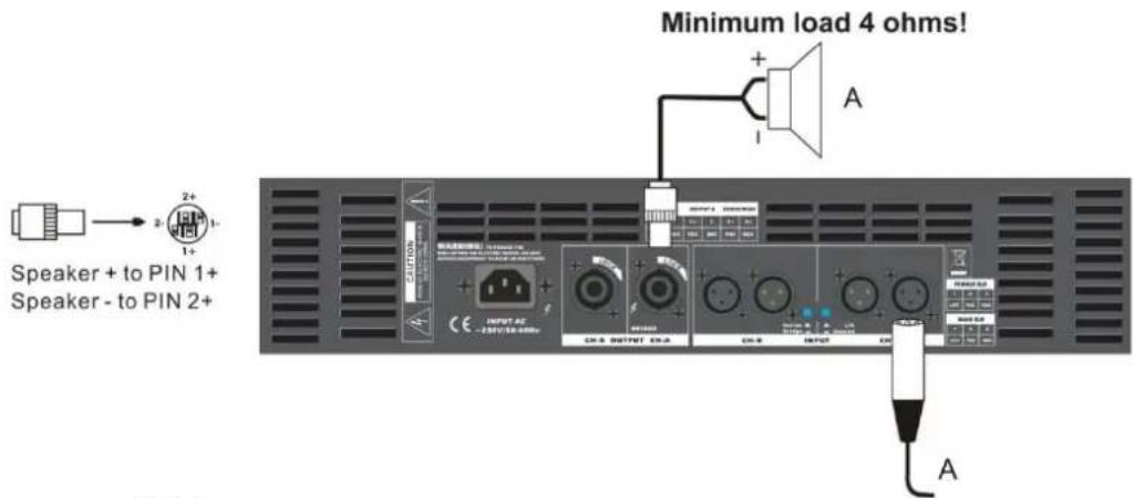
Fig. 6
Important!!!
Absolute minimum nominal load Impedance for bridge operation is 4 Ohm.
Connecting amplifier outputs to oscilloscopes or other test equipment while the amplifier is in bridged mode may damage both the amplifier and test equipment!
Connection Cables
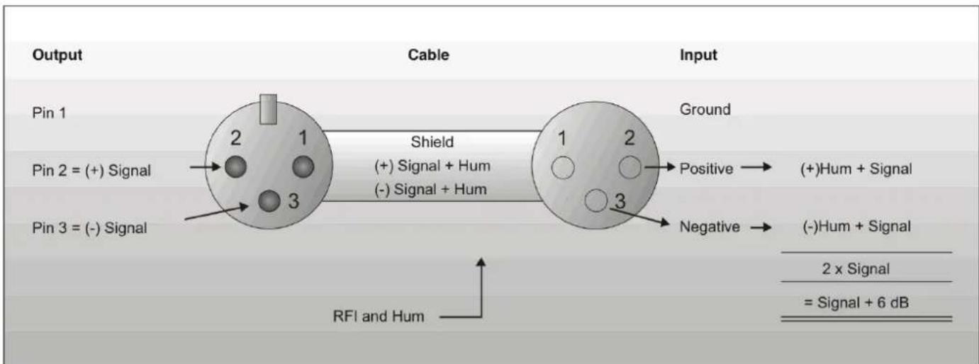
Take care of your cables, always holding them by the connectors and avoiding knots and twists when coiling them: This gives the advantage of increasing their life and reliability. Periodically check your cables. A great number of problems (faulty contacts, ground hum, discharges, etc.) are caused entirely by using unsuitable or faulty cables.
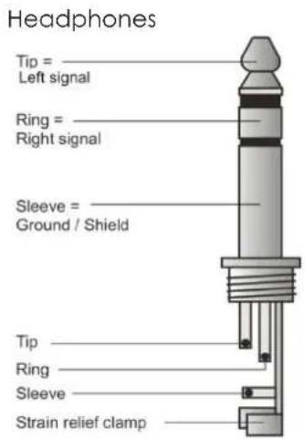
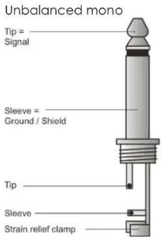
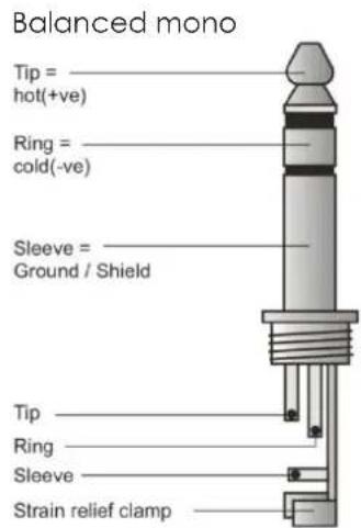
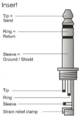
flowchart
graph LR
    A["Pin 1"] -->|2 + (+) Signal| B["Cable"]
    C["Pin 2 = (-) Signal"] -->|3 + (+) Signal + Hum| B
    D["Pin 3 = (-) Signal"] -->|3 + (-) Signal + Hum| B
    B -->|1 + (+) Signal + Hum| E["Ground"]
    B -->|2 + (-) Signal + Hum| F["Positive"]
    B -->|3 + (-) Signal + Hum| G["Negative"]
    H["RFI and Hum"] --> B
    I["2 x Signal"] --> J["Ground"]
    K["= Signal + 6 dB"] --> L["Ground"]
Compensation of interference with balanced connections
Balanced use with XLR connectors
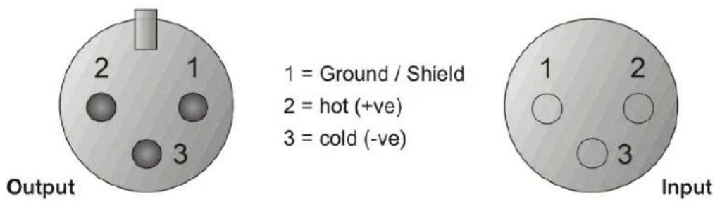
$$ 1 = \text { Ground / Shield } $$
$$ 2 = \text { hot } (+ \mathrm{ve}) $$
$$ 3 = \text { cold } (- \text { ve }) $$
For unbalanced use PIN 1 and PIN 3 have to be bridged
Maintenance
The DAP Audio DSA requires almost no maintenance. However, you should keep the unit clean. Disconnect the mains power supply, and then wipe the cover with a damp cloth. Do not immerse in liquid. Do not use alcohol or solvents.
Keep connections clean. Disconnect electric power, and then wipe the DMX and audio connections with a damp cloth. Make sure connections are thoroughly dry before linking equipment or supplying electric power.
Replacing a Fuse
Power surges, short-circuit or inappropriate electrical power supply may cause a fuse to burn out. If the fuse burns out, the product will not function whatsoever. If this happens, follow the directions below to do so.
- Unplug the unit from electric power source.
- Insert a screwdriver into the slot in the fuse cover. Turn the screwdriver to the left, at the same time gently push a bit (Turn and Push). The fuse will come out.
- Remove the broken fuse. If brown or unclear, it is burned out.
- Insert the replacement fuse into the holder where the old fuse was. Reinsert the fuse cover. Be sure to use a fuse of the same type and specification. See the product specification label for details.
Troubleshooting
DAP Audio DSA-series Amplifiers.
This troubleshooting guide is meant to help solve simple problems. If a problem occurs, carry out the steps below in sequence until a solution is found. Once the unit operates properly, do not carry out following steps.
- If the device does not operate properly, unplug the device.
- Check the fuse, power from the wall, all cables, etc.
- If all of the above appears to be O.K., plug the unit in again.
- If you are unable to determine the cause of the problem, do not open the amplifier, as this may damage the unit and the warranty will become void.
- Return the amplifier to your Dap Audio dealer.
Product Specifications
| Power | DSA-250 | DSA-400 | DSA-600 | DSA-800 | DSA-1000 |
| Stereo, 2Ω | 2x 325Wrms | 2x 355Wrms | 2x 625Wrms | 2x 800Wrms | 2x 1000Wrms |
| Stereo, 4Ω | 2x 250Wrms | 2x 400Wrms | 2x 500Wrms | 2x 625Wrms | 2x 800Wrms |
| Stereo, 8Ω | 2x 160Wrms | 2x 260Wrms | 2x 330Wrms | 2x 420Wrms | 2x 500Wrms |
| Bridge mono, 8Ω | 500Wrms | 800Wrms | 1000Wrms | 1250Wrms | 1600Wrms |
| Bridge mono, 4Ω | 650Wrms | 710Wrms | 1250Wrms | 1600Wrms | 2000Wrms |
| Performance | |||||
| Frequency response | 35Hz - 20kHz, -1dB | ||||
| THD at rated output power | <0,1% | ||||
| Damping | >350 | >350 | >450 | >450 | >450 |
| Slew rate (at 1kHz) | 32V/μs | 32V/μs | 38V/μs | 50V/μs | 50V/μs |
| S/N Ratio (A- weighted) | 106dB A-weighed | ||||
| Input sensitivity | 1.0V, +2.2dBu | ||||
| Maximum input voltage | +22dBu | ||||
| Input impedance(20Hz - 20kHz balanced) | 20kΩ balanced10kΩ unbalanced | ||||
| Protection | Clip limiter (fixed), high temperature, short circuit,DC voltage, subsonic (fixed) | ||||
| Output modes (selectable) | stereo/ bridge | ||||
| Cooling | multi speed fan | ||||
| Airflow | front to rear | ||||
| Input/ link connectors | XLR/ XLR | ||||
| Output connectors | speakon | ||||
| Ground lift switch | yes | ||||
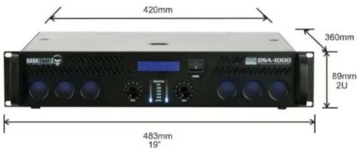
| Dimensions (WxHxD) | 483 x 89 x 335mm | ||||
| Weight | 14,5kg | 16,5kg | 16,5kg | 16,5kg | 16,5kg |
| Power supply | 230V/ 50-60Hz | ||||
| Main fuse | F10A | F10A | F10A | F15A | F15A |
Design and product specifications are subject to change without prior notice.

Website: www.Dap-audio.info
Email: service@highlite.nl
Wire Gauge Chart (Metric)
Wire Gauge Chart (AWG: American Wire Gauge)
| Stranded Cable Length( ) (AWG) | Wire Gauge (8 ohm load) (4 ohm load) (2 ohm load) | Power Loss % | Power Loss % | Power Loss % | |
| 5 18 0.81 | 1.61 3.2 | ||||
| 16 0.51 1.02 | 2 | ||||
| 14 0.32 0.64 | 1.28 | ||||
| 12 0.2 0.4 | 0.8 | ||||
| 10 | 0.128 | 0.25 0.51 | |||
| 10 | 18 1.61 3.2 | 6.2 | |||
| 16 1.02 2 | 4 | ||||
| 14 0.64 1.28 | 2.5 | ||||
| 12 0.4 0.8 | 1.6 | ||||
| 10 0.25 0.51 | 1.01 | ||||
| 40 | 18 | 6.2 | 11.9 | 22 | |
| 16 | 4 | 7.7 | 14.6 | ||
| 14 2.5 | 5 | 9.6 | |||
| 12 1.6 3.2 | 6.2 | ||||
| 10 1.01 2 | 4 | ||||
| 8 | 0.6 1.2 2.4 | ||||
| 80 | 18 | 11.9 | 22 | 37 | |
| 16 7.7 | 14.6 | 26 | |||
| 14 | 5 | 9.6 | 17.8 | ||
| 12 3.2 6.2 | 11.8 | ||||
| 10 | 2 | 4 | 7.7 | ||

© 2012 Dap Audio.
- DAP Audio DSA-250, DSA-400, DSA-600, DSA-800, DSA-1000 Product Guide
- Warning 2
- Description....5
- Operation....8
- Connection cables 9
- Maintenance 11
- Troubleshooting 12
- Product specifications 13
- Wire Gauge Charts....14
- WARNING
- FOR YOUR OWN SAFETY, PLEASE READ THIS USER MANUAL CAREFULLY BEFORE YOUR INITIAL START-UP!
- Unpacking Instructions
- SAFETY INSTRUCTIONS
- IMPORTANT:
- OPERATING DETERMINATIONS
- ⚠️ Return Procedure ⚠️
- Note: If you are given an RMA number, please include the following information on a piece of paper inside the box:
- Claims
- Description of the device
- Features
- Frontpanel
- Rack Mounting Holes.
- Fan Inlet Grills.
- LCD display
- Input Attenuators.
- Protect LEDs.
- Clip LEDs.
- Active LEDs.
- Level Indicator.
- AC Power Switch
- Backpanel
- AC Inlet.
- Output B Speakon Connector.
- Output A Speakon Connector.
- Channel B In/Through Connectors
- Stereo/ Bridge Switch.
- GND Switch.
- Channel A In/Through Connectors
- Air cooling windows
- Operation
- Installation
- Connecting Power / Circuit Size Requirements.
- Cooling System and Requirements.
- Connecting Inputs.
- Connecting Outputs.
- Mode Selection
- Stereo Mode
- Important !!!
- Parallel Mode
- Bridged Mono Mode
- Important!!!
- Connection Cables
- Balanced use with XLR connectors
- Maintenance
- Replacing a Fuse
- Troubleshooting
Brand : DAP-Audio
Model : DSA-250
Category : Receiver