
FZP 6005 E - Hedge Trimmer Fieldmann - Free user manual and instructions
Find the device manual for free FZP 6005 E Fieldmann in PDF.


| Product Type | Pole-Mounted Pruner (Hedge Trimmer) |
| Brand | Fieldmann |
| Model | FZP 6005 E |
| Power | 600 W |
| Voltage / Frequency | 230–240 V / 50 Hz |
| Chain Pitch | 3/8" |
| Bar Length | 25 cm |
| Cutting Length | 250 mm |
| Cutting Speed | 10 m/s |
| Total Length (Retracted / Extended) | 2.05 m / 2.65 m (without guide bar) |
| Weight | 3.5 kg |
| Sound Power Level (Measured / Guaranteed) | 99 dB(A) / 102 dB(A) |
| Oil Tank Capacity | 100 ml |
| Telescopic Pole Length Range | 2.0 m to 2.6 m |
| Adjustable Chainsaw Head Angles | 0°, 15°, 30° |
| Chain Tensioning | Tool-less adjustment via adjusting bolt |
| Safety Features | Scabbard, two-hand operation, trigger lock, anti-electric shock distance ≥10 m from power lines |
| Included Accessories | Pole pruner, guide bar, chain, scabbard, shoulder strap, user manual |
| Recommended Lubricant | Chain oil (not included) |
| Maintenance Requirements | Regular chain sharpening, guide bar cleaning and reversal, oil level checks |
Frequently Asked Questions - FZP 6005 E Fieldmann
User questions about FZP 6005 E Fieldmann
0 question about this device. Answer the ones you know or ask your own.
Ask a new question about this device
Download the instructions for your Hedge Trimmer in PDF format for free! Find your manual FZP 6005 E - Fieldmann and take your electronic device back in hand. On this page are published all the documents necessary for the use of your device. FZP 6005 E by Fieldmann.
USER MANUAL FZP 6005 E Fieldmann
natural_image
Abstract black-and-white spiral pattern with no text or symbolsFIELDMANN®
Home & Garden Performance
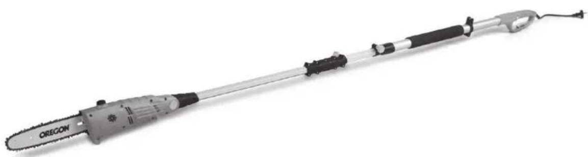
natural_image
Oregon electric tool with black and silver components, isolated on white background (no text or symbols visible)FZP 6005-E
natural_image
Technical illustration of a pair of hair tools, one with a chain and the other with a straight blade (no text or symbols present)2
natural_image
3D rendering of a mechanical tool with a spool and chain attachment (no text or symbols visible)3
4
5
6
natural_image
Illustration of a hand pressing down on a mechanical component (no text or symbols)7
8
natural_image
3D rendering of a mechanical chain saw with labeled component '27' (no text or symbols beyond label)9
natural_image
Illustration of a medical or laboratory device with labeled angles (0°, 15°, 30°) and internal components (no text or symbols on the device itself)10
11

natural_image
Line drawing of a worker holding a long tool with a labeled component 'A' (no text or symbols beyond label)12
13
14
15 16
17
Pole-Mounted Pruner
OPERATING INSTRUCTIONS
TABLE OF CONTENTS
PICTURE ANNEX 3
- GENERAL SAFETY REGULATIONS 14
Important safety notices
Packaging
Instructions for use
-
SYMBOLS 15
-
MACHINE DESCRIPTION AND PACKAGE CONTENT 17
-
SAFETY INSTRUCTIONS 17
-
SAFETY INSTRUCTIONS WHEN WORKING WITH POLE-MOUNTED PRUNER 20
-
POLE-MOUNTED PRUNER ASSEMBLY 21
-
SAWCHAIN TENSIONING 22
-
ADJUSTING SAWCHAIN TENSION 22
-
ADJUSTING CHAINSAW HEAD ANGLE 23
-
ADJUSTING TELESCOPIC POLE LENGTH 23
-
OPERATING THE POLE-MOUNTED PRUNER 23
-
TOOL CLEANING AND MAINTENANCE 24
-
SAWCHAIN SHARPENING 25
-
SAWCHAIN REPLACEMENT 27
-
STORAGE 28
-
TECHNICAL DATA 28
-
DECLARATION OF CONFORMITY 29
-
DISPOSAL 30
WARRANTY CERTIFICATE, WARRANTY TERMS 108 - 109
1. GENERAL SAFETY REGULATIONS
Important safety notices
* Unpack the product carefully and be sure not to throw away any part of the package before having found all components of the product.
- Keep the product in a dry place out of reach of children.
Read all cautions and instructions. The failure to adhere to warning cautions and instructions may result in an accident, fire and/or a serious injury.
Packaging
The product is placed in a package preventing damage during transport. This package is a raw material therefore it can be handed-over for recycling.
Instructions for use
Before beginning to work with the machine, read the following safety rules and instructions for use. Familiarize with operating elements and the proper use of the device. Keep the manual in a safe place for future reference. We recommend keeping the original package including the inner packaging materials, cash voucher and guarantee card for a period of warranty at minimum. For a case of transportation, pack the machine into the original box from the manufacturer, thus ensuring a maximum protection of the product during a possible transport (e.g. moving or sending into a service station).

Note: If you hand the machine over to next persons, hand it over together with the manual. Adherence to the attached instructions for use is a precondition for the proper use of the machine. The operation manual includes also instructions for operation, maintenance and repairs.
The manufacturer does not take any responsibility for accidents or damages resulting from the failure to adhere to this manual.
2. SYMBOLS

Do not expose the tool to rain.

natural_image
Icon of a person reading a book inside a circle (no text or symbols)Before using the tool, read carefully this operating manual.
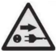
If the power cord is damaged, immediately unplug the tool.

natural_image
Circular icon depicting a person wearing a helmet and safety goggles (no text or symbols)Always use hard hat, goggles and hearing protection while working.
natural_image
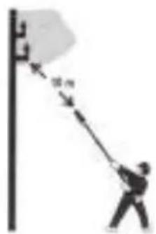
Silhouette of a person pulling a flag with arrows, no text or symbols visibleDanger of fatal injury caused by electric shock! Maintain distance of at least 10 m from overhead electrical power lines
natural_image
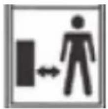
Symbol of a person walking with a block and double-headed arrow, representing mobility or communication (no text present)DANGER! Do not start the tool if there are children, bystanders or animals near you.

natural_image
Icon of two white gloves inside a dark circular background (no text or symbols)Use protective gloves while working.

natural_image
Simple icon of a boots inside a circle (no text or symbols)Use solid insulated working footwear.

natural_image
Icon of a person wearing headphones inside a circular frame (no text or symbols)Use ear protection.

natural_image
Icon of a white hand gripping a wrist, enclosed in a gray circle (no text or symbols)Wear work gloves.

Beware of falling branches.
3. MACHINE DESCRIPTION AND PACKAGE CONTENT
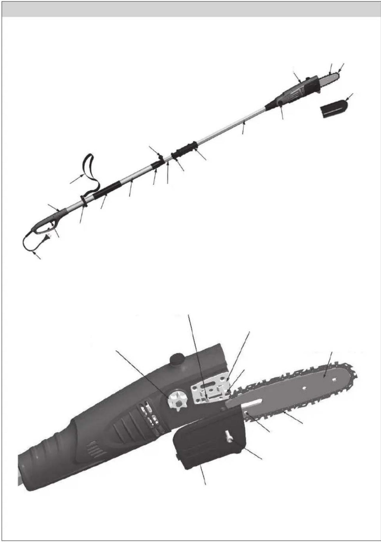
Machine Description (see Fig. 1)
| 1. | Scabbard | 15. | Clamp |
| 2. | Chainsaw | 16. | Handle |
| 3. | Guide bar | 17. | Switch |
| 4. | Drive | 18. | Plug |
| 5. | Adjusting button | 19. | Guide bar |
| 6. | Connecting handle | 20. | Saw chain |
| 7. | Connecting collar | 21. | Adjusting hole |
| 8. | Arresting element | 22. | Guide bar bolt |
| 9. | Arresting element | 23. | Sprocket cover |
| 10. | Front handle | 24. | Sprocket |
| 11. | Collar | 25. | Adjusting block |
| 12. | Rear handle | 26. | Adjusting plate |
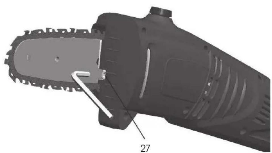
| 13. | Grip area | 27. | Adjusting bolt |
| 14. | Strap |
Package Content
Remove the machine carefully from the packaging and check the completeness of the following parts:
Pole pruner
Bar
Bar cover
Chain
Shoulder strap
Instructions for use
4. SAFETY INSTRUCTIONS
ATTENTION!
Familiarize yourself with all the warning and safety instructions and with the tool operating instructions.
ATTENTION!
Failure to adhere to warning or safety instructions may result in electric shock, fire and/or serious injury.
ATTENTION!
Keep all the warning and safety instructions in a practical place for future reference.

Note: The term "power tool" in all the warning instructions specified hereafter means mains-operated (corded) power tool.
Work area safety
Keep work area clean and well lit. Cluttered or dark areas at the workplace invite accidents.
Do not operate power tools in explosive atmospheres, such as in the presence of flammable liquids, gases or dust. Power tools create sparks which may ignite the dust or fumes.
Keep children and bystanders away while operating a power tool. Distractions can cause you to lose control over the tool.
Electrical safety
Power tool plugs must match the mains outlet. Never modify the plug in any way. Do not use any adapter plugs with earthed (grounded) power tools. Unmodified plugs and matching outlets will reduce the risk of electric shock.
Avoid body contact with earthed or grounded surfaces, such as pipes, radiators, ranges and refrigerators. There is an increased risk of electric shock if your body is earthed or grounded.
Do not expose power tools to rain or wet conditions. Water entering a power tool will increase the risk of electric shock.
Do not abuse the cord. Never use the cord for carrying, pulling or unplugging the power tool. Keep cord away from heat, oil, sharp edges or moving parts. Damaged or entangled cords increase the risk of electric shock.
When operating a power tool outdoors, use an extension cord suitable for outdoor use. Use of a cord suitable for outdoor use reduces the risk of electric shock.
If operating a power tool in a damp location is unavoidable, use a residual current device (RCD) protected supply. Use of residual current device (RCD) reduces the risk of electric shock.

Note: The term "residual current device" (RCD) may be substituted by the term "ground fault circuit interrupter" (GFCI) or "earth leakage circuit breaker" (ELCB).
Personal safety
Stay alert, watch what you are doing and use common sense when operating a power tool. Do not use a power tool while you are tired or under the influence of drugs, alcohol or medication. A moment of inattention while operating power tools may result in serious personal injury.
Use personal means of protection. Always wear eye protection. Safety equipment such as dust mask, non-skid safety shoes, hard hat, or hearing protection used in conformity with the working conditions will reduce personal injuries.
Avoid accidental starting. Ensure the switch is in the off-position before connecting the battery, storing or carrying the power tool. Carrying power tools with your finger on the switch or plugging in power tools that have the switch on invites accidents.
Remove any adjusting tools or wrenches before turning the power tool on. An adjusting tool or wrench left attached to a rotating part of the power tool may result in personal injury.
Do not overreach. Keep proper footing and balance at all times. This enables better control of the power tool in unexpected situations.
Dress properly. Do not wear loose clothing or jewellery. Keep your hair, clothing and gloves away from moving parts. Loose clothes, jewellery or long hair can be caught in moving parts,.
If devices are provided for the connection of dust extraction and collection facilities, ensure these are connected and properly used. Use of these devices can reduce dust-related hazards.
Power tool use and maintenance
Do not force the power tool. Use only the correct power tool for your application. The correct power tool will do the job better and safer at the rate for which it was designed.
Do not use the power tool if the switch does not turn it on and off. Any power tool that cannot be controlled with the switch is dangerous and must be repaired.
* Unplug the power cord from the mains outlet before making any adjustments, changing accessories, or storing power tools. Such preventative safety measures reduce the risk of starting the power tool accidentally.
Store idle power tools out of the reach of children and do not allow persons unfamiliar with the power tool or these instructions to operate the power tool. Power tools are dangerous in the hands of untrained users.
* Maintain power tools. Check for misalignment or binding of moving parts, pay particular attention to cracks, breakage of parts and any other condition that may affect the power tool's operation. If damaged, have the power tool repaired before use. Many accidents are caused by poorly maintained power tools.
Keep cutting tools sharp and clean. Properly maintained cutting tools with sharp cutting edges are less likely to bind and are easier to control.
Use the power tool, accessories and tool bits etc., in accordance with these instructions and in the manner intended for the particular type of power tool, taking into account the given working conditions and the work to be performed. Use of the power tool for operations other than those for which the power tool is intended could result in hazardous situations.
Service
Have your power tool serviced by a qualified repair person using only original replacement parts. This will ensure that the safety of the power tool is maintained.
Storage
only carry and store the tool with the scabbard fitted
* carefully clean the tool and carry out adequate maintenance before storing
before carrying, secure the tool against fuel leakage, damage or injury
5. SAFETY INSTRUCTIONS WHEN WORKING WITH POLE-MOUNTED PRUNER
natural_image
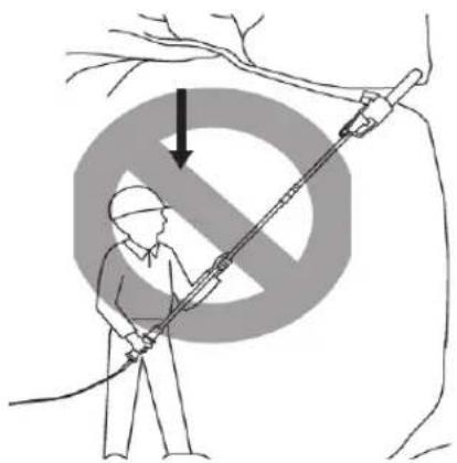
Illustration of a worker using a long tool to lift a tree, with a large 'no' symbol overlay (no text or symbols on the diagram itself)Never stand directly under the branch you are cutting. Always stand outside the area of falling chippings.
natural_image
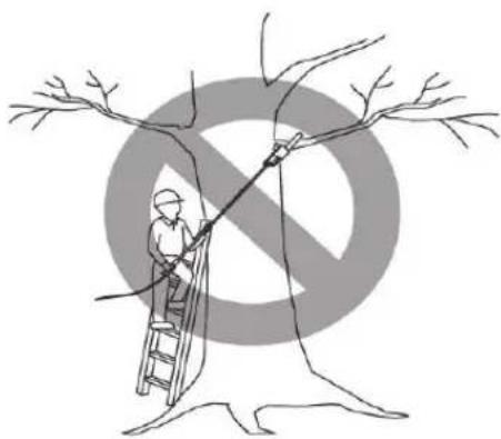
Illustration of a person climbing a tree with a ladder, under a large 'no' symbol (no text or symbols present)Never work from a ladder or other unstable equipment while working with a chain saw. Always grasp the chain saw with both hands. While cutting, apply firm and continuous pressure on the chain saw but do not try to force the chain saw through the wood being cut. Do not use the chain saw for cutting branches having larger diameter than the length of the guide bar.
natural_image
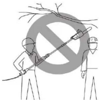
Illustration of two workers holding tools under a large 'no' symbol (no text or symbols present)While cutting, prevent movement of persons near the chain saw. Ensure safe movement of persons in sufficient distance from the cutting point.
natural_image
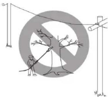
Illustration of a person using a power tool to extend a tree with a large crossed-out circle in the background (no text or symbols)Do not use the chain saw near cable, power and telephone lines. Maintain distance of at least 10 m from all electrical power lines while working with a chain saw.
6. POLE-MOUNTED PRUNER ASSEMBLY
Chain saw assembly
ATTENTION! The cutting edges of the saw chain are very sharp. Always wear work gloves while handling the chain.
Spread the saw chain.
Turn the adjusting bolt (27) counter-clockwise (see Fig. 1). Turn the adjusting bolt (27) until the adjusting block (25) moves to the rear part of the adjusting plate (26).
Attach the guide bar (19) to the saw body. Place the rear part of the bar (19) between the adjusting plate (26) and the sprocket (24).
⚠️ ATTENTION! Make sure you have inserted the adjusting block (25) into the adjusting hole (21) on the guide bar (19).
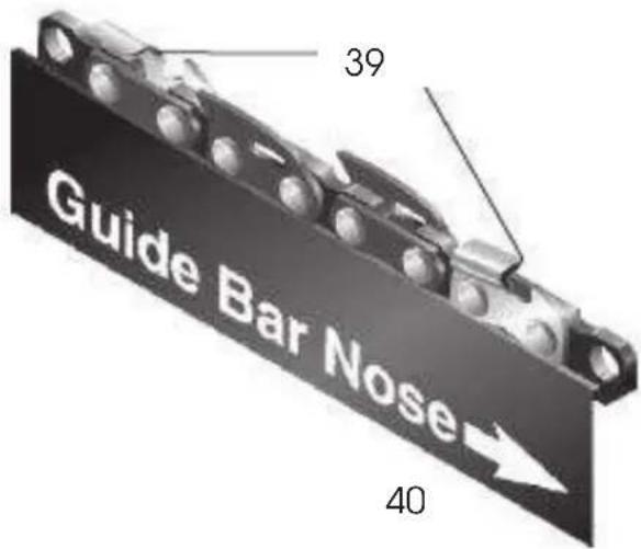
Place the chain (20) around the sprocket wheel and then along top groove of the guide bar (19) and around the guide bar nose.
Note: Make sure the cutting edges of the chain (20) are facing in the correct direction. Position the chain (20) so the cutting edges on top of the guide bar (19) face to the guide bar nose (see Fig. 1).
Adjust the tension of the saw chain (20). Follow the instructions specified in the Chapter Adjusting Chainsaw Tension.
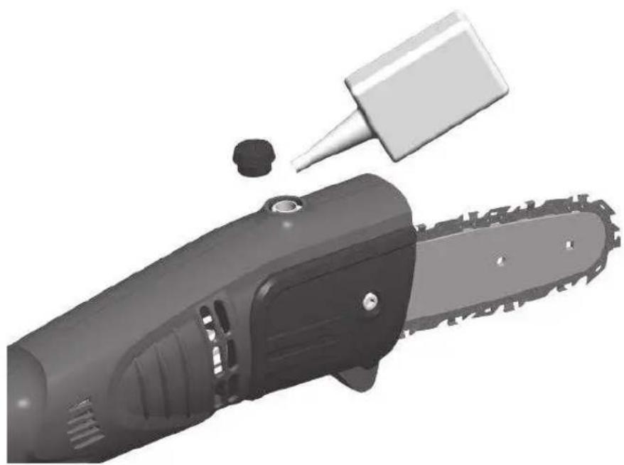
Pour oil into the chain saw oil container.
⚠️ ATTENTION! After pouring the oil, do not forget to close the cap (see Fig. 2)
Assembly of the tool
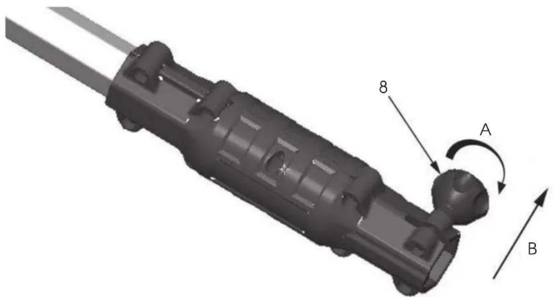
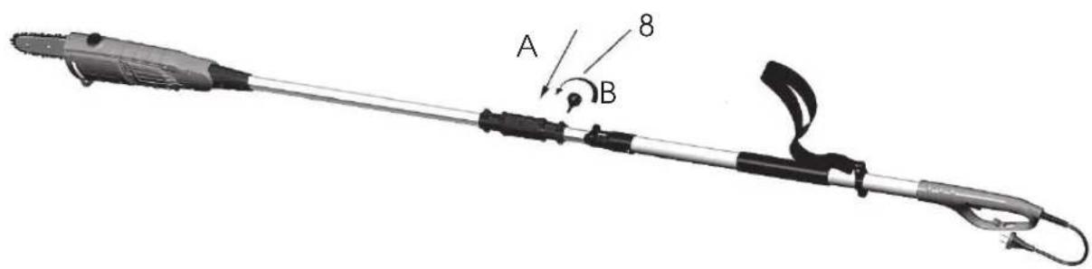
Loosen in the direction (A) and remove in the direction (B) the arresting element (8) on the connecting handle (6) (see Fig. 3).
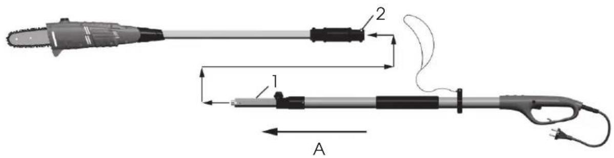
Insert the rear handle into the front part in the direction (A) (see Fig. 4). Make sure the groove 1 (groove 1 on the front pole) snapped into the slot 2 (slot 2 in the connecting handle) (see Fig. 4).
Insert in the direction (A) the arresting element (7) into the threaded hole (see Fig. 5) and screw it tight in the direction (B). Make sure the connection is properly tightened.
7. SAWCHAIN TENSIONING
ATTENTION! Before you start tensioning the saw chain, unplug the power cord from the mains outlet. Contact of a human body with running chain may result in a serious or fatal injury.
⚠️ ATTENTION! The cutting edges of the saw chain are very sharp. Always wear work gloves while handling the chain.
⚠️ ATTENTION! When cleaning the chain saw
Note: The saw chain has already been correctly tensioned in the manufacturing plant. New chain will always stretch. Frequently check the tension of a new chain during the first 2 hours (always unplug the power cord from power supply first). Allow chain cool down. When checking the saw chain tension, proceed as specified below.
* Disconnect the chainsaw from power supply.
Place the saw on a solid surface so that you can check the chain tension.
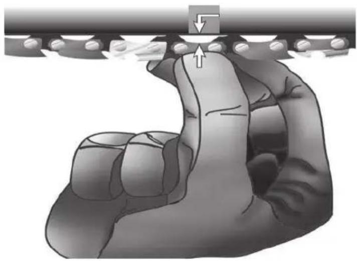
Slightly pull the chain at the bottom edge of the guide bar, retract it approx. 8 mm from the bar body and release it again (see Fig. 6). If the chain returns to its original position, the tension is correct. Minor slack (approx. 4 mm or less) of the chain from the bottom edge of the bar is permissible.
8. ADJUSTING SAWCHAIN TENSION
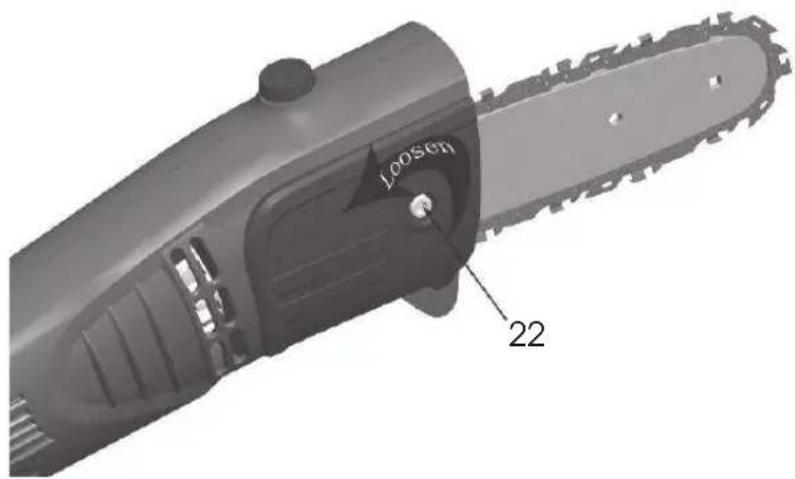
Prior to adjusting saw chain tension, loosen the guide bar bolt (22). (see Fig. 7)
Turn the adjusting bolt (27) on the front side of the chainsaw body in clockwise direction until the chain is sufficiently tensioned. (see Fig. 8)
Use your hand protected by a work glove and retract the saw chain (20) again.
Carefully adjust the chain to prevent overtensioning. Overtensioning of the chain causes excessive wear and tear and reduces the lifetime of both the guide bar and the chain.
After tensioning the chain, re-tighten the adjusting bolt of the guide bar (see Fig. 7)
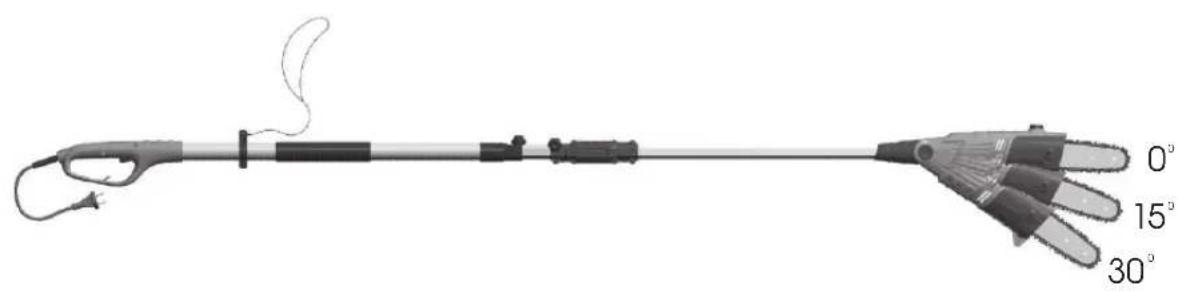
9. ADJUSTING CHAINSAW HEAD ANGLE (Fig. 9)
The chainsaw head can be adjusted up to 3 different working angles. 0 degrees, 15 degrees and 30 degrees.
With one hand press the adjusting button PUSH and turn the trimmer head into the desired position. After releasing the button, the trimmer head is automatically locked in the set position.
10. ADJUSTING TELESCOPIC POLE LENGTH
The chainsaw is equipped with a telescopic pole the length of which ranges from 2.0 m (fully retracted) up to 2.6 m (fully extracted). The locking bush with arresting element will ensure sufficient strength of the pole in any length.
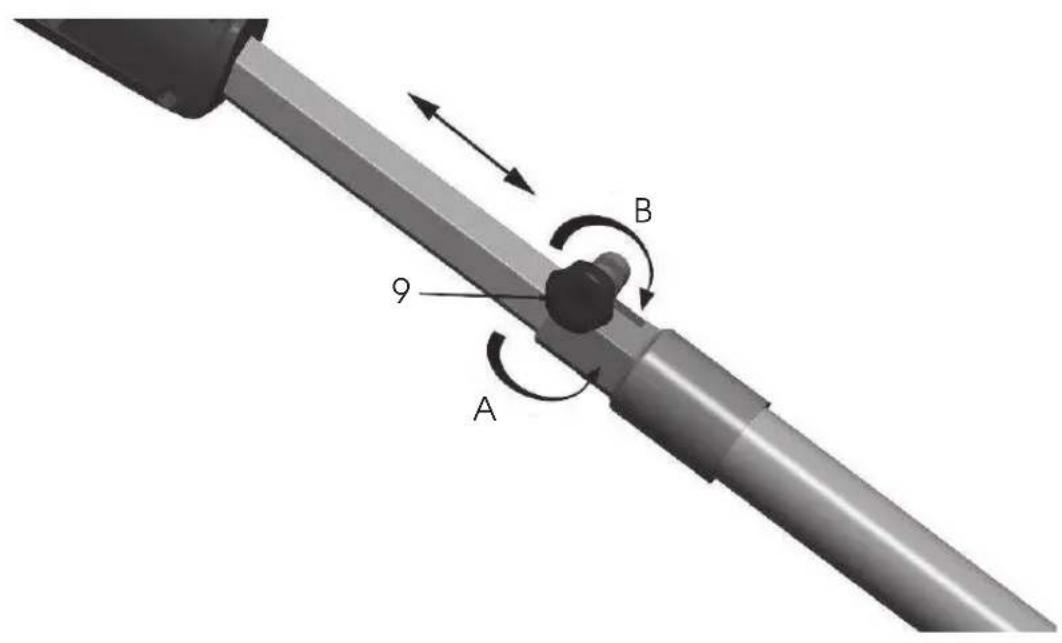
To extend the pole, loosen the arresting element (9) in the direction (A) (see Fig. 10). The pole can be easily extracted.
Pull the front part of the pole and extract it up to the desired length. Note: Always extend the pole only up to the minimum length required for cutting the particular shrubbery.
To lock the pole in the position, tighten the arresting element (9) in the direction (B) (see Fig. 10).
11. OPERATING THE POLE-MOUNTED PRUNER
Fill up the oil container.
Plug the power cord to the outlet.
Grasp the chainsaw pole with your both hands. Hold the pole at prescribed grip positions (A) and use the supporting strap. (see Fig. 11) Hold the pole firmly. The thumbs and fingers must firmly wrap both the pole and the handle of the tool.
Stand so that you are stable and balanced. Stand with your legs apart. Distribute your weight evenly on both feet.
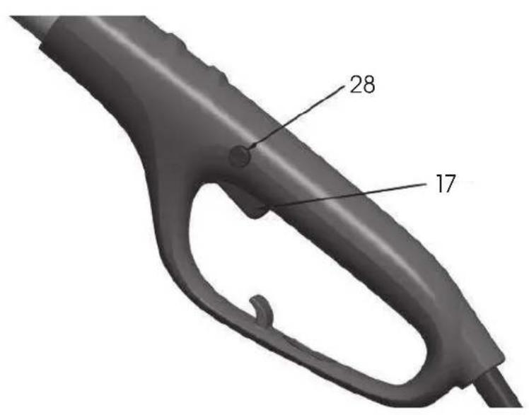
As soon as you are ready to trim, press the trigger lock (28) and subsequently the actual tool switch (17) (see Fig. 12). This will start the chainsaw. Once the switch is released, the chainsaw stops. Before cutting, the chainsaw must always be running.
When cutting, place the moving saw chain near the branch. Hold the chainsaw telescopic pole firmly to avoid undesired bouncing or side sliding of the saw.
After the cut, remove the saw from the cutting point at full speed. Release the switch and stop the saw. Before turning the pole down to the ground make sure the saw chain stopped moving.
* Never cut near other persons to prevent their injury.
12. TOOL CLEANING AND MAINTENANCE
Cleaning the chainsaw body
Keep the chainsaw body clean. When cleaning, use a soft cloth soaked in a soap water. Use this cloth to carefully clean the chainsaw body.
Guide bar maintenance
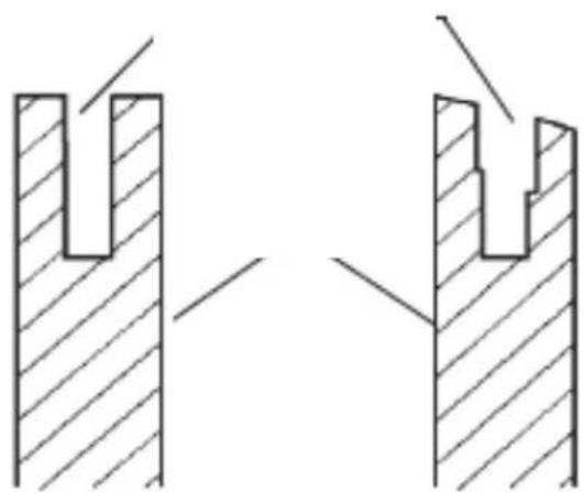
Most problems with the guide bar occur as a result of uneven wear and tear. Uneven wear and tear occurs mostly due to incorrect chain sharpening and incorrect adjustment of the raker. If the bar is worn out unevenly, the guiding groove is getting wider (See Figure). Consequently, it results in chain rattling and rivets falling off. It is impossible to make straight cuts with the saw. In such case replace the guide bar by a new one.
Before chain sharpening, always check the state of the guide bar. Using worn out or damaged guide bar is very dangerous. Using worn out or damaged guide bar will result in chain damage. Cutting using such tool will also be significantly more difficult and laborious.
natural_image
Pure mechanical cross-section diagram showing two views of a U-shaped component with hatched fill (no text or symbols)Regular maintenance of the guide bar
Dismantle the guide bar (19) from the chainsaw body.
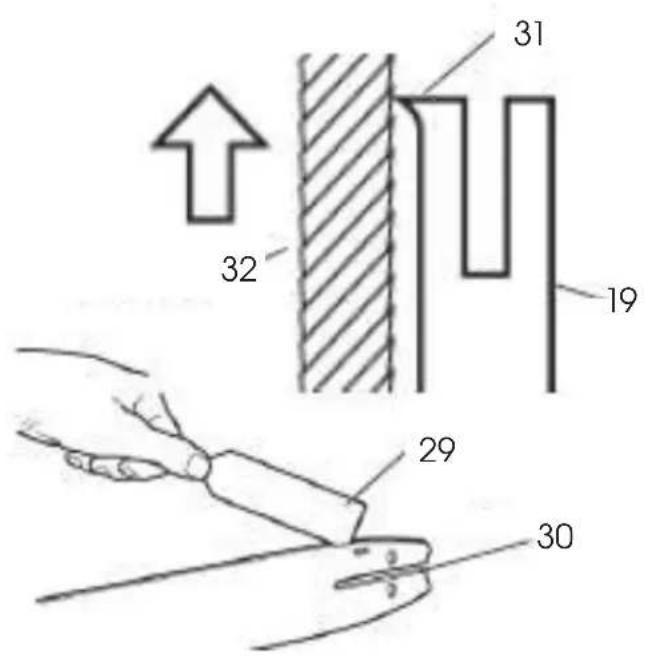
Regularly remove wood dust from the guide bar groove. While cleaning, use a scraper (29) or a wire (see Fig. 13).
At the end of each working day, clean the oil grooves (30).
Remove burr from the sides of the bar (31). Grind in the side edges using a flat file (32). Replace the guide bar, if:

Note: When replacing the guide bar, follow the instructions specified in the Chapter Spare parts and accessories. Correct bar type is available in the List of Parts.
13. SAWCHAIN SHARPENING
Keep the saw chain sharp. Cutting will be significantly faster and particularly safer. Dull chain increases wear and tear of the sprocket, guide bar, chain and drive. If you have to force the chainsaw while only wood dust and a few chippings are produced while cutting, it means that the chain is dull.
Equipment required for saw chain sharpening
Purchase the following equipment from your local vendor, tool shop or hobby market.
Round file 5/32"
Raker
File guide rail 5/32"
Chops
Middle-sized flat file
Saw chain sharpening
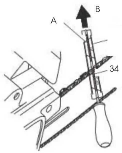
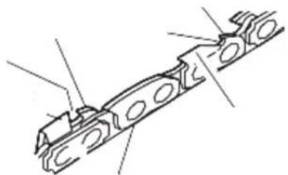
Use guide rail (33) (see Fig. 14) for filing under the angle of 30^ (mark A, Fig. 14).
Adjust the saw chain tension to the correct level.
* Fix the guide rail into the chops to ensure the chain is in a stable position.

Note: Do not fix the chain itself.
Press the round file 5/32" (34), inserted in to the guide rail (33), into the groove between the upper plate and the chain raker. The chain should touch both the upper plate and the raker (see Fig. 14).

Note: File in the centre of the guide bar.

Note: The figure shows the position of the guide rail of the file and the teeth filing direction on the left side of the chain.
Place the file guide rail to the desired angle (mark A, Fig. 14). Check whether the mark 30^ on the file guide rail is aligned with the centre of the guide bar. This way you make sure you are filing under the angle of 30^ .
natural_image
Technical line drawing of a mechanical component with circular features (no text or symbols)1 - Right-hand side of the chain
2 - Upper plate, right-hand side of the chain
3 - Raker, right-hand side of the chain
4 - Groove
5 - Raker, left-hand side of the chain
6 - Groove
7 - Upper plate, left-hand side of the chain
File the tooth from inside out (in the direction B, Fig. 14) until it is sharp. File only in this direction.

Note: Two or three file strokes should suffice to make the tooth sharp.
Raker filing
Sharpening of the chain teeth will result in reduced tolerance of the raker. After each second or third sharpening, it is necessary to adjust the raker.
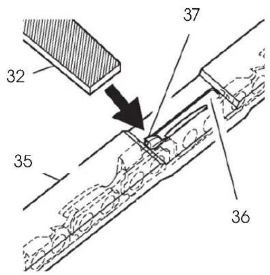
Place the tool for raker modification (.025") (35) firmly onto the top edge of two teeth. Make sure the groove of the tool snapped into the groove of the raker (36) (see Fig. 15).
Use middle-sized flat file (32) (see Fig. 15). File the raker (37) down to the level of the tool for raker modification.
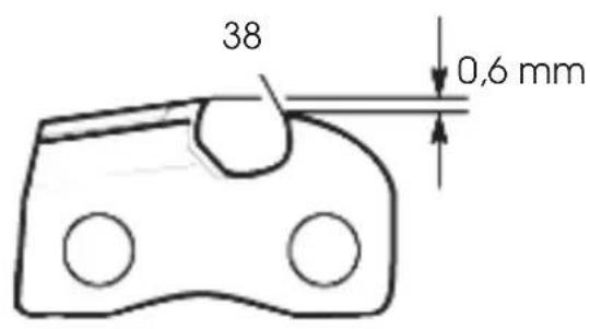
Remove the tool for raker modification. Using a flat file (32) round off the front side (38) of the raker (see Fig. 16).

Note: After a few manual sharpening hand the saw chain for sharpening to an authorised service centre or sharpen it using a special sharpening machine. This way you will restore even sharpening of all teeth.
14. SAWCHAIN REPLACEMENT
⚠️ ATTENTION! When replacing the saw chain, do not fix the chainsaw or the guide bar into the chops.
Always replace the chain if the teeth are excessively worn out or cannot be sharpened or if the chain breaks. Use only original replacement chain according to specification in this instruction manual. When replacing a chain, always replace the sprocket wheel too. This way you ensure the correct position of the chain during movement. (Note: The specification of the correct chain and sprocket type is available in the List of Parts.)
When performing the following steps, make use of the drawing in Fig. No. 1.
Loosen and remove the guide bar bolt.
Remove the sprocket cover.
Remove the saw chain.
Place the new chain around the sprocket wheel, along the top groove of the guide bar and around the guide bar nose.
Note: Make sure the cutting edges of the chain are facing in the correct direction. Position the chain so the cutting edges on top of the guide bar face to the guide bar nose (40) (see Fig. 17 and arrow on the saw side cover).
Before placing the sprocket cover into position, check whether the adjusting tip is inserted into the adjusting hole of the guide bar.
Reinstall the sprocket cover back to the saw body.
Attach the sprocket cover using the guide bar bolt.
⚠️ ATTENTION! Use only your hand while tightening the bolt.
* Adjust the tension of the saw chain.
Tighten the guide bar bolt using a hexagonal wrench.
⚠️ ATTENTION! Make sure you did not place the saw chain onto the guide bar in the opposite direction. Otherwise, the saw will produce excessive vibrations and will not cut.
15. STORAGE
If you do not use the saw for a period exceeding 30 days, proceed as follows.
Empty the oil container.
Remove and clean the guide bar and the chain. Immerse the guide bar and the chain in a paraffin-based or soap-based cleaning bath.
Then dry the guide bar and the chain.
Place the chain into a container filled with oil. This will prevent it from corroding.
Slightly apply oil onto the guide bar.
Wipe the chainsaw body with a cloth. When cleaning, use a soft cloth soaked in a soap water.
Store the chainsaw
16. TECHNICAL DATA
| Power 600 W | |
| Voltage/Frequency: 230 V - 240 V / 50 Hz | |
| Chain pitch 3/8" | |
| Bar length 25 cm | |
| Cutting speed 10 m/s | |
| Total length 2,05 m -2,65 m (without guide bar) | |
| Vibrations hand/arm, weighted root-mean-square acceleration | < 2,5 m/s ^2 |
| Total length 2,3 m -2,9 m | |
| Cutting length 250 mm | |
| Weight 3,5 kg | |
| Sound power level LWA measured 99 dB(A)/guaranteed 102 dB(A) | |
| Container capacity 100ml |
The User's Manual is in a specific language version.
17. DECLARATION OF CONFORMITY
Product / brand: POLE MOUNTED PRUNER ELECTRICAL / FIELDMANN
Type / model: FZP 6005-E 230V, 600W, 50Hz, Class II
The product is inline with regulations listed below:
EC Directive for Noise 2000/14/ES
EC Council Directive 2006/42/EC Machinery
EC Directive for Electromagnetic Compatibility (EMC) No.2004/108/EC
EC Directive for RoHS 2002/95/EC
and norms:
EN 60745-1:2009+A11:2010
EN ISO 11680-1:2011
EN 55014-1:2006+A1:2009+A2:2011
EN 55014-2:1997+A1:2001+A2:2008
EN 61000-3-2:2006+A1:2009+A2:2009
EN 61000-3-3:2008
CE label: 14
Company FAST ČR, a.s. is authorized to act on behalf of manufacturer.
Manufacturer:
FAST ČR, a.s.
Černokostelecká 2111, 100 00 Praha 10, Czech Republic
VAT no: CZ26726548
Place of issuance: Prague

Name: Ing. Zdeněk Pech
Chairman of the Board
Date of issuance: 7.5.2014 Signature:
18. DISPOSAL
INSTRUCTIONS AND INFORMATION ON DISPOSAL OF USED PACKAGING.
Put any used package material to the place determined by the municipality for waste disposal.
DISPOSAL OF USED ELECTRIC AND ELECTRONIC EQUIPMENT
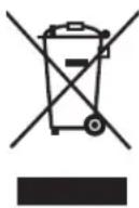
This symbol on products or accompanying documents means that used electric or electronic products must not be put to ordinary municipal waste. Hand over such products to determined collection points for proper disposal, restoration and recycling. Alternatively, in some countries of the European Union or other European countries you can return your products to your local dealer when you buy an equivalent new product. By dutiful disposal of this product you can preserve precious natural resources and you help prevent any potential adverse effects on the environment and human health which could be the results of wrong waste disposal. Ask your local authority or the nearest collection point for additional details. In case of improper disposal of this waste kind penalties can be imposed in accordance with national regulations.
For companies in the European Union countries
Should you want to dispose of electric and electronic devices, ask your dealer or vendor for necessary information.
Disposal in other countries outside the European Union
Should you want to dispose of this product, ask your local authorities or your dealer for necessary information about disposal method.
This product fulfils all basic requirements of the EU directives that apply to it.

Text, design and technical specifications can change without prior notice and we reserve the right for their change.

- FIELDMANN®
- Pole-Mounted Pruner
- OPERATING INSTRUCTIONS
- TABLE OF CONTENTS
- GENERAL SAFETY REGULATIONS
- Important safety notices
- Packaging
- Instructions for use
- SYMBOLS
- MACHINE DESCRIPTION AND PACKAGE CONTENT
- Package Content
- SAFETY INSTRUCTIONS
- ATTENTION!
- Work area safety
- Electrical safety
- Personal safety
- Power tool use and maintenance
- Service
- Storage
- SAFETY INSTRUCTIONS WHEN WORKING WITH POLE-MOUNTED PRUNER
- POLE-MOUNTED PRUNER ASSEMBLY
- Chain saw assembly
- Assembly of the tool
- SAWCHAIN TENSIONING
- ADJUSTING SAWCHAIN TENSION
- ADJUSTING CHAINSAW HEAD ANGLE (Fig. 9)
- ADJUSTING TELESCOPIC POLE LENGTH
- OPERATING THE POLE-MOUNTED PRUNER
- TOOL CLEANING AND MAINTENANCE
- Cleaning the chainsaw body
- Guide bar maintenance
- Regular maintenance of the guide bar
- SAWCHAIN SHARPENING
- Equipment required for saw chain sharpening
- Saw chain sharpening
- Raker filing
- SAWCHAIN REPLACEMENT
- STORAGE
- TECHNICAL DATA
- DECLARATION OF CONFORMITY
- The product is inline with regulations listed below:
- and norms:
- Manufacturer:
- DISPOSAL
- INSTRUCTIONS AND INFORMATION ON DISPOSAL OF USED PACKAGING.
- DISPOSAL OF USED ELECTRIC AND ELECTRONIC EQUIPMENT
- For companies in the European Union countries
- Disposal in other countries outside the European Union
Brand : Fieldmann
Model : FZP 6005 E
Category : Hedge Trimmer