
Stilo (2012) - Automobile FIAT - Free user manual and instructions
Find the device manual for free Stilo (2012) FIAT in PDF.


| Product Type | Automobile |
| Brand | Fiat |
| Model | Stilo (2012) |
| Category | Compact Car |
| Body Style | 5-door Hatchback |
| Engine | 1.4L 16V (95 hp) |
| Fuel Type | Petrol |
| Fuel Consumption (combined) | 6.8 L/100 km |
| Dimensions (L x W x H) | 4182 mm x 1784 mm x 1525 mm |
| Wheelbase | 2600 mm |
| Curb Weight | 1200 kg |
| Seating Capacity | 5 |
| Transmission | 5-speed manual / 6-speed automatic (optional) |
| Safety Features | ABS, dual airbags, ESP (optional) |
| Maintenance Interval | Every 15,000 km or 12 months |
| Recommended Oil | SAE 5W-40 synthetic |
| Parts Availability | Widely available online and at dealers |
| Repair Difficulty | Moderate, DIY possible with manual |
| Manual Language | English |
| Manual Pages | 274 |
Frequently Asked Questions - Stilo (2012) FIAT
User questions about Stilo (2012) FIAT
0 question about this device. Answer the ones you know or ask your own.
Ask a new question about this device
Download the instructions for your Automobile in PDF format for free! Find your manual Stilo (2012) - FIAT and take your electronic device back in hand. On this page are published all the documents necessary for the use of your device. Stilo (2012) by FIAT.
USER MANUAL Stilo (2012) FIAT
FIAT STILO
OWNER HANDBOOK
Dear Customer,
Thank you for selecting Fiat and congratulations on your choice of a Fiat Stilo.
We have written this handbook to help you get to know all your new Fiat Stilo features and use it in the best possible way.
You should read it right through before taking the road for the first time.
You will find information, tips and important warnings regarding the driving of your car to help you derive the maximum from your Fiat Stilo technological features.
You are recommended to read carefully the warnings and indications, marked with the respective symbols, at the end of the page:

personal safety;

the car's wellbeing;

environmental protection.
The enclosed Warranty Booklet lists the services that Fiat offers to its Customers:
☐ the Warranty Certificate with terms and conditions for maintaining its validity
☐ the range of additional services available to Fiat Customers.
Best regards and good motoring!
This Owner Handbook describes all Fiat Stilo versions. As a consequence, you should consider only the information which is related to the engine and bodywork version of the car you purchased.
MUST BE READ!
REFUELLING

Petrol engines: only refuel with unleaded petrol with octane rating (RON) not less than 95 conforming to the European specification EN 228.
Diesel engines: only refuel with diesel fuel conforming to the European specification EN590. The use of other products or mixtures may irreparably damage the engine with invalidation of the warranty due to the damage caused.
ENGINE STARTING

Petrol engines with mechanical gearbox: make sure that the handbrake is engaged; set the gearshift lever to neutral; fully depress the clutch without pressing the accelerator, then turn the ignition key to AVV and release it as soon as the engine has started.
Petrol engines with Selespeed gearbox: keep the brake pedal fully depressed; turn the ignition key to AVV and release it as soon as the engine has started; the transmission sets to neutral automatically.
Diesel engines: turn the ignition key to MAR and wait for the warning lights 📄 and 00 to go off; turn the ignition key to AVV and release it as soon as the engine has started.
PARKING ON FLAMMABLE MATERIAL

While working, the catalyst develops a very high temperature. Do not park the car over grass, dry leaves, pine needles or any other inflammable materials: risk of fire.
RESPECTING THE ENVIRONMENT

The car is fitted with a system that allows continuous diagnosis of the components correlated with emissions to ensure better respect for the environment.
ELECTRICAL ACCESSORIES
If, after buying the car, you decide to add electrical accessories (that will gradually drain the battery), visit a Fiat Dealership. They can calculate the overall electrical requirement and check that the car's electric system can support the required load.

CODE card
Keep the code card in a safe place, not in the car. The code card shall be used for requesting additional keys.

SCHEDULED SERVICING
Correct maintenance of the car is essential for ensuring it stays in tip-top condition and safeguards its safety features, its environmental friendliness and low running costs for a long time to come.

THE OWNER HANDBOOK CONTAINS...
... information, tips and important warnings regarding the safe, correct driving of your car, and its maintenance. Pay particular attention to the symbols ▲ (personal safety) ▲ (environmental protection) ▲ (the car's wellbeing).

DASHBOARD AND CONTROLS
DASHBOARD 5
INSTRUMENT PANEL 6
SYMBOLS 8
THE FIAT CODE SYSTEM....8
THE KEYS 10
ALARM 17
IGNITION SWITCH....20
INSTRUMENTS....21
MULTIFUNCTION DISPLAY 23
TRIP COMPUTER 34
SEATS 37
HEAD RESTRAINTS 41
STEERING WHEEL 42
REARVIEW MIRRORS.... 43
HEATING/CLIMATE CONTROL SYSTEM 44
HEATING AND VENTILATION 46
MANUAL CLIMATE CONTROL SYSTEM 48
AUTOMATIC TWO-ZONE
CLIMATE CONTROL SYSTEM 51
EXTERNAL LIGHTS 57
WINDOW WASHING....60
CRUISE CONTROL 64
CEILING LIGHTS 67
CONTROLS 68
INTERIOR FITTINGS 70
"SKYWINDOW"(BLADE SUNROOF) 74
DOORS 79
POWER WINDOWS 80
BOOT 81
BONNET 92
ROOF RACK/SKI RACK 93
HEADLIGHTS....94
ABS SYSTEM 95
ESP SYSTEM 97
EOBD SYSTEM 99
SOUND SYSTEM....100
ACCESSORIES PURCHASED BY THE OWNER ..... 101
"DUALDRIVE" ELECTRIC POWER
STEERING SYSTEM 102
PARKING SENSORS 103
AT THE FILLING STATION 105
PROTECTING THE ENVIRONMENT 108
DASHBOARD
The presence and the position of the instruments and warning lights may vary according to the versions.

fig. 1
1. Side window air vent - 2. Adjustable and swivel air vent - 3. External light stalk - 4. Instrument panel - 5. Adjustable and swivel air vent - 6. Hazard light switch - 7. Sound system controls - 8. Front passenger air bag - 9. Upper glovebox - 10. Lower glovebox - 11. Controls for heating, ventilation and climate control - 12. Windscreen/rear window wiper/trip computer stalk - 13. Ignition key and ignition switch - 14. Driver air bag - 15. Steering wheel locking/release stalk - 16. Control unit access door - 17. Bonnet opening lever - 18. Set of switches for lights and menu opening/setting.
INSTRUMENT PANEL

fig. 2

fig. 3
1.416V - 1.616V - 1.816V versions
A Rev counter
B Engine coolant temperature gauge and excessive temperature warning light
C Fuel level gauge with reserve warning light
D Speedometer (speed indicator)
E Multifunction display.
The rev counter of versions with Sele-speed transmission is fitted with warning light ☐.
1.9 Multijet versions
A Rev counter
B Engine coolant temperature gauge and excessive temperature warning light
C Fuel level gauge with reserve warning light
D Speedometer (speed indicator)
E Multifunction display.
The rev counter of versions with Sele-speed transmission is fitted with warning light ☐.
2.420v Selespeed Abarth versions
A Rev counter
B Engine coolant temperature gauge and excessive temperature warning light
C Fuel level gauge with reserve warning light
D Speedometer (speed indicator)
E Multifunction display.

fig. 4
SYMBOLS
Special coloured labels have been attached near or actually on some of the components of your car. These labels bear symbols that remind you of the precautions to be taken as regards that particular component.
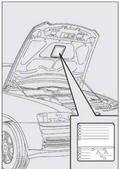
The plate summarising the symbols used can be found under the bonnet fig. 5.
natural_image
Technical line drawing of a car hood with internal components and a zoomed-in inset showing internal wiring (no text or symbols)fig. 5
F0C0145m
THE FIAT CODE SYSTEM
To further protect you car from theft, it has been fitted with an engine immobilising system. This system is automatically activated when the ignition key is removed.
An electronic device, in fact, is fitted in each ignition key grip. The device transmits a radio-frequency signal when the engine is started through a special aerial built into the ignition switch. The modulate signal, which changes each time the engine is started, is the "password" by means of which the control unit recognises the key and enables to start the engine.
OPERATION
Each time the car is started turning the ignition key to MAR, the Fiat CODE system control unit sends a recognition code to the engine control unit to deactivate the inhibitor.
The code is sent only if the Fiat CODE system control unit has recognised the code transmitted from the key.
Each time the ignition key is turned to STOP, the Fiat CODE system deactivates the functions of the engine electronic control unit.
If the code has not been recognised correctly, the instrument panel warning light will turn on.
In this case, the key should be moved to the STOP position and then back to MAR; if the lock continues, possibly try again with the other key provided with the car. If it is still not possible to start the car contact a Fiat Dealership.
IMPORTANT Every key has its own code, which must be memorised by the system control unit. To memorise new keys, up to a maximum of eight, apply solely to Fiat Dealership taking with you the CODE card and the keys, a personal identity document and the car's ownership documents. The codes of the keys not provided during the new memorising procedure are erased from the memory. This is to ensure that any lost or stolen keys can no longer be used to start the car.
Warning light coming on when driving
☐ If the warning light ☑ turns on, this means that the system is running a self-test (for example for a voltage drop).
☐ If the warning light Ⓞ continues to stay on, contact a Fiat Dealership.

The electronic components inside the key may be damaged if the key is submitted to sharp knocks.
THE KEYS
CODE CARD
Together with the keys you will receive the CODE card fig. 6 to be presented to Fiat Dealership when requesting additional keys.
IMPORTANT In order to ensure perfect efficiency of the electronic devices contained inside the keys, they should never be exposed to direct sunlight.

fig. 6
F0C0001m

All the keys and the CODE card must be handed over to the new owner when selling the car.

fig. 7
FOC0508m
KEY WITHOUT REMOTE CONTROL (where provided)
The key is fitted with a metal insert A-fig. 7, operating:
□ the ignition switch
☐ doors and tailgate locks
☐ the fuel lid locking/unlocking (on versions featuring fuel filler cap with lock)
☐ windows and Skywindow sunroof (where provided) opening/closing
□ the dead lock device (where provided)
□ the switch to deactivate the passenger's air bag and rear side bags (where provided).

fig. 8
F0C0327m
KEY WITH REMOTE CONTROL
The key is fitted with a metal insert A-fig. 8, operating:
□ the ignition switch
☐ doors and tailgate locks
☐ the fuel lid locking/unlocking (on versions featuring fuel filler cap with lock)
☐ windows and Skywindow sunroof (where provided) opening/closing
□ the dead lock device (where provided)
□ the switch to deactivate the passenger's air bag and rear side bags (where provided).
Button ☑ for remote unlocking of doors, tailgate and fuel filler cap. Button ☑ for remote locking of doors, tailgate and fuel filler cap. Button ☑ for remote opening of the tailgate. Button B for power-assisted opening of the metal insert A.
To refit the metal insert into the key grip, keep button B pressed and turn the metal insert in the direction shown by the arrow until hearing the click as it locks into place. Then release button B. Led C (where provided) comes on when sending the control to the alarm system receiver. To know the operating logics of the key with remote control and every possible and modifiable setting, see paragraph "Alarm" in this section.

If locking button is inadvertently pressed from the passenger compartment, when getting out of the car only the doors being used will unlock; the tailgate will stay locked. To realign the system, press again the locking/unlocking buttons /

WARNING
Button B-fig. 8 should only be pressed when the key is away from the body, in particular from the eyes and from objects that can be spoilt (e.g. clothes). Make sure the key can never be touched by others, especially children, who may inadvertently press the button.

natural_image
Line drawing of a car door with buttons and display (no text or symbols)Opening the doors and the tailgate
Briefly press button 🔒 for remote un-locking of doors and tailgate and simultaneous alarm (where provided) deactivation, timed switching on of the internal ceiling lights and double flashing of direction indicators (for versions/markets where applicable).
Press button 🔒 for more than 2 seconds to open the windows and the Skywindow (where provided).
For Multi Wagon versions, pressing twice rapidly button 🙏 will open the rear window lid (where provided).
Once doors are unlocked, if you do not open one door or the tailgate within few seconds, the system will lock all doors/tailgate again automatically.
Doors will be unlocked automatically if the fuel inertial cut-off switch comes into operation.
Locking the doors and the tailgate
Briefly press button Ⓞ for remote locking of doors and tailgate and simultaneous alarm (where provided) activation, switching off of the internal ceiling lights and single flashing of direction indicators.
Press button 🔒 for more than 2 seconds to open the windows and the Skywindow (where provided). If the button is briefly pressed twice, the dead lock device is activated (see next paragraph "Dead lock device").
If one or more doors are open locking will not be activated and the door led A-fig. 11 and direction indicators will flash rapidly. If only the tailgate is open the doors will lock.
Opening the tailgate by the remote control
Press and keep button 📄 pressed to open the tailgate by remote control even if the alarm (where provided) is on.
Opening the tailgate is accompanied by the direction indicators flashing twice; closing is accompanied by a single flash only if the alarm is on.
If the alarm is on, when the tailgate is opened the alarm system switches off volumetric protection and the tailgate perimetral protection sensor.
IMPORTANT If the remote control does not work properly, it is still possible to carry out the above mentioned operations by using the metal insert of the key.
When closing the tailgate again, volumetric and perimetral protection sensors are restored.

natural_image
Line drawing of a car's hood open to reveal the engine compartment, showing engine and dashboard components (no text or symbols)Opening the rear heated window lid (MultiWagon versions)
On MultiWagon versions, pressing twice button rapidly, obtains opening of the rear heated window lid (see fig. 10).

Leds on the driver's door
When locking the doors, led A-fig. 11 switches on for about 3 seconds and than starts flashing (deterrence function).
Once doors are locked, if one or more doors or the tailgate are not closed correctly, the led and direction indicators start flashing quickly.

fig. 12
Request for additional remote controls
The system can recognise up to 8 remote controls. Should a new remote control be necessary, contact a Fiat Dealership, taking with you the CODE card, a personal identity document and the car's ownership documents.

fig. 13
Replacing the battery of the key with remote control
If, when pressing button 🔒, 🔒, or 🔒, the led F-fig. 12 (where provided) on the key flashes briefly only once, the battery should be replaced with an equivalent one that can be purchased at common stores.
Battery replacement:
☐ press button A and move the metal insert B to open position;
□ turn the screw C to ☐ using a fine bit screwdriver;
☐ take out the battery case D and replace the battery E making sure that the bias is correct;
☐ re-insert the battery holder D in the key and lock it turning the screw C to ☑.

Used batteries are harmful to the environment. They should be disposed of as specified by law in the special containers
provided, or take them to a Fiat Deal- ership, which will deal with their dis- posal.
DEAD LOCK DEVICE (where provided)
This safety device enables to inhibit:
☐ door internal handles and safety lock button;
☐ button A-fig. 13 for locking/unlocking the doors, placed on the driver door panel mask;
thus hindering doors opening from inside the passenger's compartment in case of attempt to break-into (e.g. window breaking).
The dead lock device guarantees the best protection against unwanted access. Therefore, it should be actuated every time the car is parked and left unattended.

WARNING
Once the dead lock device has been actuated, doors
cannot be opened from inside the car in any way whatsoever. For this reason, make sure there are no persons left inside the car.

WARNING
If the battery of the key with remote control is down, the
dead lock device can only be activated through the metal insert of the key in the revolving plugs of the doors as described previously: in this case the dead lock device is active only on the rear doors.
Device activation
The device is automatically activated on every door in the following cases:
□ turning twice the key without remote control (where provided) in closing direction;
□ pressing twice button 🔒 of the key with remote control.
Device activation is signalled by three flashings of the direction indicators and flashing of the led on the driver door panel (see the table on next page).
If one of the doors is not perfectly closed, the dead lock device will not activate, thus preventing that a person getting into the car from the open door remains blocked inside the passenger's compartment when she/he closes the door.
Device deactivation
The device is deactivated automatically on every door in the following cases:
□ when unlocking the doors;
□ when unlocking only the driver's door;
☐ when turning the ignition key to MAR.
The main functions that can be activated with the keys (with or without remote control) are the following:
| Type of key | Door opening | Door closing | Window and Skywindow opening (where provided) | Window and Skywindow closing (where provided) | Dead lock (where provided) | Tailgate opening |
| Key without remote control (where provided) | Key turning counterclockwise (driver side) or clockwise (passenger side) | Key turning clockwise (driver side) or counterclockwise (passenger side) | Turning (>2 seconds) in opening position (counterclockwise driver side; clockwise passenger side) | Turning (>2 seconds) in closing position (clockwise driver side; counterclockwise passenger side) | Double key rotation in closing direction (clockwise driver side; counterclockwise passenger side) | Key rotation clockwise |
| Key with remote control | Key turning counterclockwise (driver side) or clockwise (passenger side) | Key turning clockwise (driver side) or counterclockwise (passenger side) | Turning (>2 seconds) in opening position (counter-clockwise driver side; clockwise passenger side) | Turning (>2 seconds) in closing position (clockwise driver side; counterclockwise passenger side) | Double key rotation in closing direction (clockwise driver side; counterclockwise passenger side) | Key rotation clockwise |
| Pressing briefly button | Brief press on button | Prolonged pressing (>2 seconds) on button | Prolonged pressing (>2 seconds) on button | Double pressing on button | Prolonged pressing (>2 seconds) on button | |
| Direction indicators flashing (only with key with remote control) | Two flashings | 1 flashing | Two flashings | 1 flashing | 3 flashings | Two flashings |
| Led on driver door | Deterrence led turning off | Turned on fixed for approx. 3 seconds and followed by deterrence led flashing | Turning off deterrence led | Deterrence led flashing | Double flashing and then deterrent led flashing | Deterrent led flashing |
ALARM (where provided)
The alarm function is provided in addition to all remote control functions previously described and it is controlled by the receiver located under the dashboard, next to the fuse box.
WHEN THE ALARM IS TRIGGERED
The alarm comes into action in the following cases:
□ unlawful opening of one of the doors, bonnet or boot (perimetral protection);
□ attempt to start the engine (turning the ignition key to MAR);
□ battery cable cutting;
□ presence of moving bodies in the passenger's compartment (volumetric protection);
□ abnormal raising/sloping of the car.
Depending on the markets, the cutting in of the alarm causes operation of the siren and direction indicators (for about 26 seconds). The ways of operating and the number of cycles may vary depending on the markets.
A maximum number of sound/sight cycles is however envisaged.
Volumetric and anti-raising protections can be cut off by operating the front ceiling light controls (see paragraphs “Volumetric protection sensors” and “Anti-raising sensor” on the following pages).
IMPORTANT The engine immobiliser function is guaranteed by the Fiat CODE system, which is automatically activated when the ignition key is removed.
HOW TO ACTIVATE THE ALARM
With the doors, bonnet and boot shut and the ignition key in the STOP position or with the key removed, point the key with remote control in the direction of the car, then press and release the button.
With the exception of certain markets, the system sounds a "beep" and the doors are locked.
Engagement of the alarm is preceded by a self-diagnostic test. If a fault is detected the system sounds a further warning "beep" and the display shows the relevant message (see section "Warning lights and messages").
In this case, switch the alarm system off by pressing button ☐, check that the doors, bonnet and tailgate are properly shut, then switch the alarm on again by pressing button ☐.
Otherwise, the door, bonnet or tailgate that is not shut properly will be excluded from the alarm system control.

If the doors, bonnet and boot are shut correctly and the control signal is repeated, the system self-diagnostics has detected a system operating fault. It is therefore necessary to contact Fiat Dealership.
IMPORTANT When operating the central door locking with the metal insert A-fig. 14 of the key, the alarm is not activated.
IMPORTANT The electronic alarm is built in compliance with the law and regulations of the different countries.
HOW TO DEACTIVATE THE ALARM
Press button 🔒 of the key with remote control.
The system will react as follows (with the exception of certain markets):
□ two brief flashes of the direction indicators;
□ two brief "beeps";
□ door unlocking.
IMPORTANT Operating the central door locking with the metal insert of the key will not deactivate the alarm.
VOLUMETRIC PROTECTION SENSORS
The volumetric sensors are inside the front ceiling light in the passenger's compartment. To make sure that the volumetric sensors are working properly, check that doors, boot, bonnet, windows and Skywindow (where provided) are shut.

Volumetric protection deactivation
If it is necessary to switch on the alarm when animals or people are in the car, press button A-fig. 15 on the front ceiling light to deactivate the volumetric protection.
Deactivation is needed also in the presence of additional independent heater and when it is switched on with the remote control.
Protection cut-out stays on until activating the central door opening again.
ANTI-RAISING SENSOR
The anti-raising sensor detects any abnormal car raising/sloping, even partial (e.g.: attempt to remove a wheel).
This sensor can detect the smallest car sideslip angle changes, both longitudinally and transversally.
Sideslip angle changes lower than 0.5^/min . (e.g.: slow tyre flattening) are not considered.
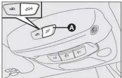
fig. 16
Anti-raising protection deactivation
To deactivate the anti-raising protection (for example when towing the car with alarm on) press button A-fig. 16 on the front ceiling light. Sensor cut-out stays on until activating the central door opening again.
INDICATIONS OF ATTEMPTS TO BREAK IN
Any attempt to break in is indicated by warning light 📋 on the instrument panel with the relevant message on the display (see section "Warning lights and messages").
HOW TO CUT OFF THE ALARM SYSTEM
To deactivate the alarm system completely (for instance during prolonged inactivity of the car) simply lock the car turning the metal insert of the key with remote control in the lock.
IMPORTANT To cut-out the electronic alarm if remote control batteries are down or the system is failing, fit the key into the ignition switch and turn it to MAR.
IGNITION SWITCH
The key can be turned to 3 different positions:
☐ STOP: engine off, key can be removed, steering column locked. Certain electrical devices (e.g.: sound system, central door locking, electronic alarm, etc.) can work.
☐ MAR: driving position. All electrical devices are powered.
□ AVV: engine starting.
The ignition switch is fitted with a safety mechanism that, in the event the engine is not started, compels the driver to turn the ignition key back to STOP before repeating the starting operation.
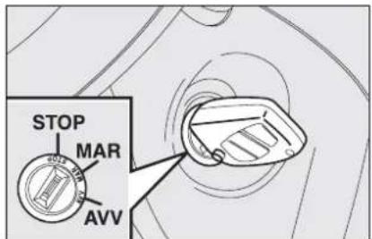
fig. 17
FOC0164m

WARNING
If the ignition device is tampered with (e.g.: attempted theft), have it checked over by a Fiat Dealership before restarting to drive.

WARNING
When getting out of the car, always remove the key to prevent any occupants from accidentally activating the controls. Remember to engage the handbrake and if the car is parked on uphill slope to engage the first gear. If the car is facing downhill, engage the reverse gear. Never leave unsupervised children in the car.
STEERING COLUMN LOCK
Engaging
When the key is at STOP remove the key and turn the steering wheel until it locks.
Disengaging
Rock the steering wheel slightly as you turn the ignition key to MAR.

WARNING
It is absolutely forbidden to carry out whatever after-
market operation involving steering system or steering column modifications (e.g.: installation of anti-theft device) that could badly affect performance and safety, cause the lapse of warranty and also result in non-compliance of the car with homologation requirements.

WARNING
Never remove the ignition key while the car is moving.
The steering wheel would automatically lock as soon as you try to turn it. This also applies when the car is being towed.
INSTRUMENTS

SPEEDOMETER fig. 18
It shows the car speed.

REV. COUNTER fig. 18a
The rev counter shows engine rpm. The needle pointed to the red area (danger) indicates excessive high engine speed. Do not drive for long periods with the needle in this area.
IMPORTANT The electronic injection control system gradually shuts off the flow of fuel when the engine is "over-revving" resulting in a gradual loss of engine power.
When the engine is idling, the rev counter may indicate a gradual or sudden speed increase. This is normal as it takes place during normal operation, for example when activating the climate control system or the fan. In particular a slow change in the speed preserves the battery charge.
ENGINE COOLANT TEMPERATURE GAUGE
This shows the temperature of the engine coolant fluid and begins working when the fluid temperature exceeds approx. 50°C.
Under normal conditions, the needle should move to different positions of the scale according to the conditions of use of the car.
C - Low engine coolant temperature.
H - High engine coolant temperature.

fig. 19
FOC0528m
The turning on of the warning light A-fig. 19 (together with the message shown on the display) indicates that the coolant fluid temperature is too high; in this case, stop the engine and contact a Fiat Dealership.

If the needle reaches the red area, stop the engine immediately and contact a Fiat Dealership.
FUEL LEVEL GAUGE
This shows the amount of fuel left in the fuel tank.
The reserve warning light B-fig. 19 turns on to indicate that approx. 8 litres of fuel are left in the tank.
E - tank empty.
F - tank full (see the indications given in paragraph "At the filling station").
Do not travel with the fuel tank almost empty: the gaps in fuel delivery could damage the catalyst.
IMPORTANT If the needle sets at E with warning light B flashing, it means that the system is malfunctioning. Contact a Fiat Dealership to have the system inspected.
MULTIFUNCTION DISPLAY
Your car is fitted with the multifunction display that shows all the useful information necessary when driving.
INFORMATION ON "STANDARD" SCREEN fig. 20
The standard screen shows the following indications:
A Date
B Dualdrive electric power steering engagement, if any
C Selespeed mode (where provided) and engaged gear display
D Clock
E Odometer (covered km or miles)
F External temperature
G Headlight aiming position (only with dipped beam headlights on)

fig. 20
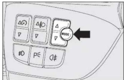
fig. 21
CONTROL BUTTONS fig. 21
To scroll the display and the related options upwards or to increase the value displayed.
MODE Brief press to open the menu and/or to move to next screen or to confirm the option required.
Long press to go back to the standard screen.
∇ To scroll the display and the related options downwards or to decrease the value displayed.
Note Buttons and activate different functions according to the following situations:
- to scroll the menu options upwards and downwards;
- to increase or to decrease values during settings.
- to scroll the menu options upwards and downwards;
- to increase or to decrease values during settings.
SETUP MENU fig. 22
The menu comprises a series of functions arranged in a “circular fashion” which can be selected through buttons and to access the different select operations and settings (setup) given below. For certain options (Set time and Units) there is a sub-menu.
The setup menu can be activated by pressing briefly button MODE.
Single presses on buttons or will scroll the setup menu options. Handling modes differ with each other according to the characteristic of the option selected.
Note If the car is equipped with Connect/Navigator, phone and audio info can be repeated on the multifunction display. For other set-up menu adjustments and/or settings, see the Connect/Navigator Supplement.
Selecting an option in the main menu without submenu:
- press briefly button MODE to select the menu option to set;
- press buttons or (by single presses) to select the new setting;
- press briefly button MODE to store the new setting and to go back to the previously selected menu option.
Selecting an option in the main menu with submenu:
- press briefly button MODE to display the first submenu option;
- press buttons or (by single presses) to scroll all submenu options;
- press briefly button MODE to select the displayed submenu option and to enter the relevant setup menu;
- press buttons or (by single presses) to select the new setting;
- press briefly button MODE to store the new setting and to go back to the previously selected submenu option.
Selecting "Set date" and "Set time":
- briefly press button MODE to select the first value to change (e.g. hours /minutes or year / month / day);
- press buttons or (by single presses) to select the new setting;
– briefly press button MODE to store the new setting and to go to the next setup menu option, if this is the last one you will go back to the previously selected option of the main menu.
Press button MODE for long:
- to quit the submenu if you are at sub-menu option setting level;
- to quit the main menu if you are at sub-menu level;
- to quit the main menu if you are at main menu option setting level;
- to quit the set up menu if you are in the main menu;
- only settings stored yet by the user (and confirmed by pressing briefly button MODE) will be saved.
The setup menu displaying is timed; when quitting the menu due to timing expiry, only settings stored yet by the user (and confirmed by pressing briefly button MODE) will be saved.

flowchart
graph TD
    A["Français"] -->|Español| B["Portugues"]
    B -->|English| C["Italiano"]
    C --> D["Deutsch"]
    D --> E["MODE briefly press button"]
    E --> F["Speed beer"]
    F --> G["SPEED BEEP"]
    G --> H["EXIT MENU"]
    H --> I["EXIT MENU"]
    I --> J["SERVICE"]
    J --> K["BELT BUZZER"]
    K --> L["Belt buzzer"]
    L --> M["BUTTON VOL."]
    M --> N["Buzzer Volume"]
    N --> O["LANGUAGE"]
    O --> P["Units"]
    P --> Q["AUTOCLOSE"]
    Q --> R["F0C2369g"]
    R --> S["KEY"]
    S --> T["SEE RADIO"]
    T --> U["SET DATE"]
    U --> V["SET TIME"]
    V --> W["Trip B DATA"]
    W --> X["HEADL. SENSOR"]
    X --> Y["Headl. sensor"]
    Y --> Z["TRIP B DATA"]
    Z --> AA["SET TIME"]
    AA --> AB["SET DATE"]
    AB --> AC["Mode briefly press button"]
    AC --> AD["Day"]
    AD --> AE["Month"]
Speed limit (Speed Beep)
With this function it is possible to set the car speed limit (km/h or mph); when this limit is exceeded the driver is immediately alerted (see section "Warning lights and messages").
To set the speed limit, proceed as follows:
- briefly press button MODE, the display will show wording (Speed Beep);
- press button or to select activation (On) or deactivation (Off) of the speed limit;
- if selecting (On), press button or to select the required speed limit and then press MODE to confirm.
Note The possible setting is between 30 and 250 km/h, or between 20 and 155 mph depending on the unit set previously (see paragraph "Distance unit (Distances)" described later. Every press on button / increases/decreases by 5 units. Keeping the button / pressed obtains the automatic fast increase or decrease. When you are near the required setting complete adjustment by single presses.
- briefly press button MODE to go back to the menu screen or press the button for long to go back to the standard screen without storing settings.
To abort the setting, proceed as follows:
- briefly press button MODE: (On) will flash on the display;
- press button : (Off) will flash on the display;
– briefly press button MODE to go back to the menu screen or press the button for long to go back to the standard screen without storing settings.
Automatic headlight sensor sensitivity adjustment (Headl. sensor) (where provided)
With this function it is possible to adjust the light sensor sensitivity according to 3 levels (level 1 = min. level, level 2 = average level, level 3 = max. level); the higher the sensitivity is, the lower is the external light intensity required to switch on the lights.
This operation can be performed also with the car moving.
To set the light level required, proceed as follows:
- briefly press button MODE, the previously set level will flash on the display;
- press button or to select the required level;
– briefly press button MODE to go back to the menu screen or press the button for long to go back to the standard screen without storing settings.
Trip B On/Off (TripB data)
Through this option it is possible to activate (On) or deactivate (Off) the Trip B (partial trip) (for further information see "Trip computer").
For activation / deactivation, proceed as follows:
- briefly press button MODE: (On) or (Off) will flash on the display (according to previous setting);
- press button or for setting;
- briefly press button MODE to go back to the menu screen or press the button for long to go back to the standard screen without storing settings.
Setting the clock (Set time)
This function enables to set the clock through two submenus: "Time" and "Mode".
To set the clock proceed as follows:
- briefly press button MODE, the display will show the two submenus "Time" and "Mode";
- press button or to scroll the two tings. submenus;
- select the required submenu and then press briefly MODE;
- if selecting "Time": briefly press button MODE, "hours" will flash on the display;
- press button or for setting;
- press button MODE, "minutes" will flash on the display;
- press button or for setting.
- if selecting "Mode": briefly press button MODE, "12h" or "24h" will flash on the display;
- press button or to select "24h" or "12h".
After setting, briefly press button MODE to go back to the submenu screen or press the button for long to go back to the main menu screen without storing set-
- press again button MODE for long to go back to the standard screen or to the main menu according to the current menu level.
Setting the date (Set date)
This function enables to update the date (day – month – year).
To correct the date proceed as follows:
– briefly press button MODE: "year" will flash on the display;
- press button or for setting;
- briefly press button MODE: "month" will flash on the display;
- press button or for setting;
- briefly press button MODE: "day" will flash on the display;
- press button or for setting.
Note Every press on button or creases/decreases by I unit. Keeping the button pressed obtains automatic fast increase or decrease. When you are near the required setting complete adjustment by single presses.
- briefly press button MODE to go back to the menu screen or press the button for long to go back to the standard screen without storing settings.
Audio info repetition (See radio)
With this function the display repeats information relevant to the sound system.
– Radio: selected radio station frequency or RDS message;
– Audio CD/MP3 CD: CD and/or track number;
To activate (On) or to deactivate (Off) sound system info displaying proceed as follows:
- briefly press button MODE: (On) or (Off) will flash on the display (according to previous setting);
- press button or for setting;
in-- briefly press button MODE to go back to the menu screen or press the button for long to go back to the standard screen without storing settings.
Door opening mode (Key)
This function enables to select the required door opening mode:
- briefly press button MODE, the display will show the wording "Key";
- press button or to select option "Open doors" or "Open all";
– briefly press button MODE to go back to the menu screen or press the button for long to go back to the standard screen without storing settings. - “Open doors”: press button 🔒 to open the doors (excluding the tailgate);
- “Open all”: press button 🔒 to open the doors and the tailgate.
Automatic central door locking when travelling (Autoclose)
When activated (On), this function locks automatically the doors when the car speed exceeds 20 km/h.
To activate (On) or to deactivate (Off) this function proceed as follows:
– briefly press button MODE, the display will show the wording "Travelling". Wordings On or Off will flash (according to previous setting);
- press button or for setting;
– briefly press button MODE to go back to the menu screen or press the button for long to go back to the standard screen without storing settings.
Setting units (Units)
With this function it is possible to set the units through three submenus: "Distances", "Consumption" and "Temperature".
To set the required unit proceed as follows:
– briefly press button MODE, the display will show the three submenus;
- press button or to scroll the three submenus;
- select the required submenu and then press briefly button MODE;
- if selecting "Distances": pressing button MODE briefly, the display will show "km" or "mi" (according to previous setting);
- press button or for setting;
- if selecting "Consumption": pressing button MODE briefly, the display will show "km/l", "l/100km" or "mpg" (according to previous setting);
If set unit is "km", the display will show fuel consumption in km/l or l/100km.
If set unit is "mi" the display will show fuel consumption in "mpg".
- press button or for setting;
- if selecting "Temperature": pressing button MODE briefly, the display will show "°C" or "°F" (according to previous setting);
- press button or to select the required level;
After setting, briefly press button MODE to go back to the submenu screen or press the button for long to go back to the main menu screen without storing settings.
- press again button MODE for long to go back to the standard screen or to the main menu according to the current menu level.
Selecting the language (Language)
Display messages can be shown in different languages: Italian, French, Spanish, Portuguese, German, English.
To set the required language proceed as follows:
- briefly press button MODE: the previously set "language" will flash on the display;
- press button or for setting;
– briefly press button MODE to go back to the menu screen or press the button for long to go back to the standard screen without storing settings.
Setting the buzzer volume (Buzzer volume)
With this function the volume of the buzzer accompanying any failure/warning indication can be adjusted according to 8 levels.
To set the required the volume proceed as follows:
- briefly press button MODE: the previously set volume "level" will flash on the display;
- press button or for setting;
– briefly press button MODE to go back to the menu screen or press the button for long to go back to the standard screen without storing settings.
Adjusting the button volume (Button vol.)
With this function the volume of the roger-beep accompanying the activation of buttons MODE, and can be adjusted according to 8 levels.
To set the required the volume proceed as follows:
– briefly press button MODE: the previously set volume “level” will flash on the display;
- press button or for setting;
– briefly press button MODE to go back to the menu screen or press the button for long to go back to the standard screen without storing settings.
S.B.R. buzzer reactivation (Belt buzzer)
This function can be only displayed after Fiat Dealership has deactivated the S.B.R. system (see paragraph "S.B.R. system" in section "Safety devices").
Scheduled Servicing (Service)
Through this function it is possible to display information connected to proper car servicing.
To display scheduled servicing info proceed as follows:
– briefly press button MODE: service in km or mi, according to previous setting, will be displayed (see paragraph "Distance unit");
- press button or to select displaying in days;
– briefly press button MODE to go back to the menu screen or press the button for long to go back to the standard screen without storing settings.
Note The "Service Schedule" includes car maintenance every 30,000 km (or equivalent value in miles) or every year; this is shown automatically, with the ignition key at MAR, starting from 2,000 km (or equivalent value in miles) or 30 days from this deadline and it is shown again every 200 km (or equivalent value in miles) or every 3 days. Below 200 km servicing indications are displayed more frequently. Servicing indication will be displayed in km or mi according to previous setting. When a programmed maintenance interval (coupon) is near to come, turning the ignition key to MAR, the display will show the message "Service" followed by the number of km/mi or days to go before car servicing. "Scheduled servicing" message is displayed in km/mi or days according to the approaching service interval. Contact a Fiat Dealership to carry out any service operation provided by the "Service schedule" or "Annual inspection plan", and to reset the display.
Exit Menu
This is the last function that closes the circular setting cycle listed in the initial menu screen.
Briefly press button MODE to go back to the standard screen without storing settings.
Press button ▼ to return to the first menu option (Speed Beep).

Instrument panel, display and button lighting adjustment (Light rheostat)
With this function it is possible to adjust the lighting (dimming/brightening) of the instrument panel, sound system display, Connect/Navigator display, two-zone climate control display and steering wheel controls.
Press buttons / fig. 23 for light adjustment to carry out required light adjustment.
Return to standard screen is automatic or by pressing briefly button MODE.
TRIP COMPUTER
GENERAL
The “Trip computer” displays information (with ignition key at MAR), relating to the operating status of the car.
This function comprises the “General trip” concerning the “complete mission” of the car (journey) and “Trip B”, concerning the partial mission of the car; this latter function is “contained” (as shown in fig. 25) within the complete mission. Both functions are resettable (reset - start of new mission).
"General Trip" displays the figures relating to:
- Range
- Trip distance
– Average consumption - Instant consumption
– Average speed
– Trip time (driving time).
"Trip B" displays the figures relating to:
– Trip distance B
– Average consumption B
– Average speed B
– Trip time B (driving time).
Note "Trip B" function can be excluded (see paragraph "Trip B On/Off"). "Range" and "Instant consumption" cannot be reset.
Values displayed
Range
This value shows the distance in km (or mi) that the car can still cover before needing fuel, assuming that driving conditions are kept unvaried. The display will show “----” if the range value is below 50 km (or 30 mi).
Trip distance
This value shows the distance covered from the start of the new mission.
Average consumption
This value shows the average consumption from the start of the new mission.
Instant consumption
This value shows instant fuel consumption (this value is updated second by second). If parking the car with engine on, the display will show “----”.
Average speed
This value shows the car average speed as a function of the overall time elapsed since the start of the new mission.
Trip time
This value shows the time elapsed since the start of the new mission.
IMPORTANT Lacking information, Trip computer values are displayed with “----”. When normal operating condition is reset, calculation of different units will restart regularly. Values displayed before the failure will not be reset.
TRIP button fig. 24
The TRIP button, set on right steering column stalk, shall be used (with ignition key at MAR), to display and to reset the previously described values to start a new mission:
- short push to display the different values;
- long push to reset and then start a new mission.

fig. 24
New mission
New mission starts after:
- "manual" resetting by the user, by pressing the relevant button;
- “automatic” resetting, when the “trip distance” reaches 4999.9 km or when the “trip time” reaches 99.59 (99 hours and 59 minutes);
- after disconnecting/reconnecting the battery.
IMPORTANT The reset operation in the presence of the screens concerning the "General Trip" makes it possible to reset also the "Trip B". The reset operation in the presence of the screens concerning only the "Trip B" makes it possible to reset only the information associated with this function.
Start of journey procedure
With ignition key at MAR, press and keep TRIP button pressed for over 2 seconds to reset.
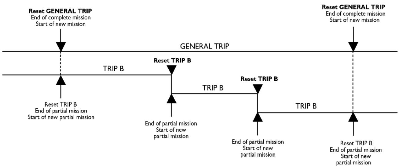
flowchart
graph LR
    A["Reset GENERAL TRIP\nEnd of complete mission\nStart of new mission"] --> B["TRIP B"]
    B --> C["Reset TRIP B\nEnd of partial mission\nStart of new partial mission"]
    C --> D["TRIP B"]
    D --> E["Reset TRIP B\nEnd of partial mission\nStart of new partial mission"]
    E --> F["TRIP B"]
    F --> G["Reset TRIP B\nEnd of partial mission\nStart of new partial mission"]
    G --> H["TRIP B"]
    H --> I["Reset GENERAL TRIP\nEnd of complete mission\nStart of new mission"]
fig. 25
SEATS
FRONT SEATS fig. 26
Moving the seat backwards or forwards
Lift the lever A (on the internal side of the seat) and push the seat forwards or backwards: in driving position the arms should rest on the rim of the steering wheel.
Seat height adjustment (where provided)
Move the lever B upwards or downwards to achieve the required height.
IMPORTANT Adjustment must be carried out only seated in the driver's seat.
Back rest angle adjustment
Turn the knob C.
Lumbar adjustment (where provided)
To adjust, turn the knob D.

fig. 26
F0C0158m
Tilting the back rest (3-door versions)
To gain access to the rear seats, pull the handle E upwards, the back rest folds and the seat is free to run forwards. When resetting the back rest, the seat returns to its original position (mechanical memory).

Only make adjustments when the car is stationary.

Fabric upholstery of your car is purpose-made to withstand common wear resulting from normal use of the car. It is
however absolutely necessary to prevent hard and/or prolonged scratching/scraping caused by clothing accessories like metallic buckles, studs, "Velcro" fixings, etc. that stressing locally the fabric could break yarns and damage the upholstery as a consequence.

Once you have released the lever, check that the seat is firmly locked in the runners by trying to move it back and
forth. Failure to lock the seat in place could result in the seat moving suddenly and the driver losing control of the car.

Seat warming (where provided) fig. 27
With ignition key at MAR, press button to switch the seat warming on/off. The led on the button will light up when the function is on.

Front passenger's seat "table" tilting (where provided)
To tilt the seat, use lever A-fig. 28 and fold the back rest at the same time.
To reset it to normal position, lift the back rest in the direction opposed to the arrow until hearing the coupling click.
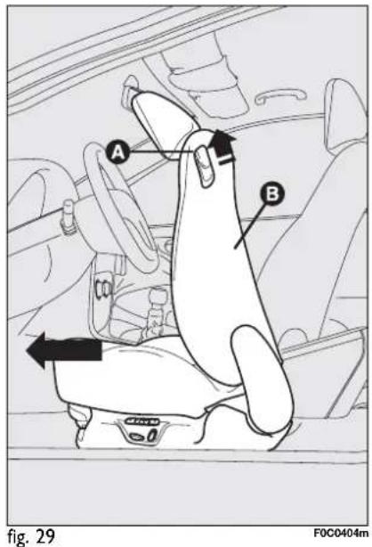
EASY ENTRY (3-door versions)
This function, operating regardless of the ignition key position, facilitates access to rear seats.
To access the rear seats lift handle A-fig. 29 and move the seat back forwards B: the seat automatically slides forward.
When the front seat back is returned to its normal position, the seat returns to its original position.
If, when returning to the original position, it finds an obstacle (e.g.: rear passenger's knees) it stops; then moves forwards of few centimetres and then it locks.
REAR SLIDING SEATS (where provided)
Back rest angle adjustment
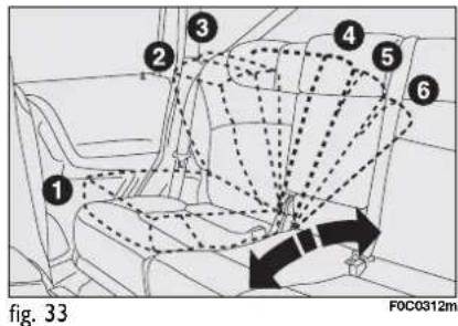
Lift handle A-fig. 30 and guide the back rest adjusting it in one of the six available positions.

Moving the seat backwards or forwards
Lift lever B taking it in the middle and move the seat backwards or forwards; the two sides can be adjusted individually.

Fabric upholstery of your car is purpose-made to withstand common wear resulting from normal use of the car. It is however absolutely necessary to prevent hard and/or prolonged scratching/scraping caused by clothing accessories like metallic buckles, studs, "Velcro" fixings, etc. that stressing locally the fabric could break yarns and damage the upholstery as a consequence.
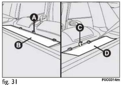
The space obtained between the rear seat back and the baggage compartment can be covered with proper boot covers B-fig. 31 (left-hand side) and D (right-hand side).
To do this, take tongues A-fig. 31 and C and leading them delicately, hook covers B-fig. 31 and D to the relevant fixings E-fig. 32 located on the back of the rear seat backs.
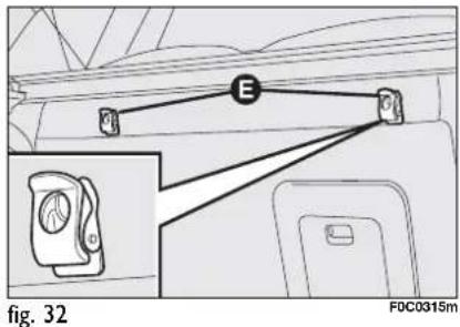
To guarantee proper seat belt fastening when travelling, the seat back shall be adjusted in 4^th position fig. 33

WARNING
Only make adjustments when the car is stationary.

WARNING
Once you have released the lever, check that the seat is cked in the runners by trying it back and forth. Failure to seat in place could result in moving suddenly and the dri-g control of the car.

WARNING
For maximum safety, keep the back of your seat up- an back into it and make sure belt fits closely across your d hips.
HEAD RESTRAINTS
FRONT
Head restraints are adjustable in height and they lock automatically in the required position.
☐ to raise: raise the head restraint until hearing the locking click.
☐ to lower: press button A-fig. 34 and lower the head restraint.

natural_image
Side-by-side comparison of a human head silhouette and a simplified illustration of a hat with arrows indicating motion (no text or symbols)fig. 34

natural_image
Diagram showing two views of a car's side profile with arrows indicating movement or force (no text or symbols present)fig. 35

WARNING
Remember that the head re- straints should be adjusted ort the back of your head and r neck. Only in this position exert their protective action.

WARNING
To optimise head restraint protective action, adjust the
seat back upright and keep your head as close as possible to the head restraint.
REAR
Rear seats are fitted with three head re- straints.
To lift out head restraint: take it completely out from the seat back (position of use) until hearing a click.
To bring it back to the original position (non-use position): press button A-fig. 35 and lower the head restraint down into its seat.
IMPORTANT Rear seat passengers shall always set the head restraints in the position of use.
STEERING WHEEL
The driver can adjust the steering wheel position both axially and in height.
Release the lever A-fig. 36 pulling it towards the steering wheel, then adjust it in the most suitable position and lock it pushing the lever A fully forwards.

fig. 36

WARNING
It is absolutely forbidden to carry out whatever aftermarket operation involving steering system or steering column modifications (e.g.: installation of anti-theft device) that could badly affect performance and safety, cause the lapse of warranty and also result in non-compliance of the car with homologation requirements.

WARNING
Any adjustment of the steering wheel position must be out only with the car station—the engine turned off.
REARVIEW MIRRORS
DRIVING MIRROR
The mirror is fitted with a safety device that causes it to be released in the event of a violent crash.
It can be moved using the lever A-fig. 37 to two different positions: normal or antiglare.
DOOR MIRRORS
Manual adjustment
When required (for example when the mirror causes difficulty in narrow spaces) it is possible to fold the mirror moving it from position A-fig. 38 to position B.

natural_image
Diagram of a car interior showing a steering wheel and dashboard, with no visible text or symbols.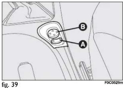

natural_image
Diagram showing two car side profiles labeled A and B, with a rotation arrow indicating direction (no text or symbols beyond labels)Electrical adjustment
Proceed as follows:
☐ use switch A-fig. 39 to select the mirror required (left or right);
☐ to adjust the mirror move the joystick B in the four directions.

When driving the mirrors shall always be in position A-fig. 38.

As the driver's door mirror is curved, it may slightly alter the perception of distance.
HEATING/CLIMATE CONTROL SYSTEM
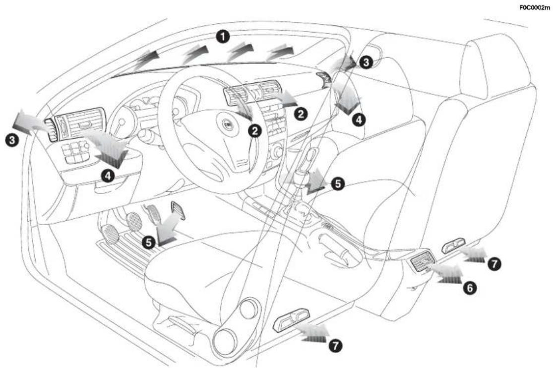
fig. 40
- Upper fixed vent for defrosting or demisting windscreen - 2. Centre adjustable vent -3. Fixed vents for defrosting or demisting side windows - 4. Side adjustable and swivel vents - 5. Lower vents - 6. Rear adjustable and swivel outlet - 7. Rear feet area fixed vents.
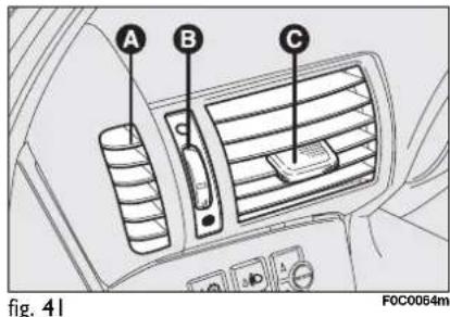
SIDE SWIVEL OUTLETS AND VENTS fig. 41
A - Fixed vent for side windows.
B - Air flow adjusting control:
● = completely closed
O = completely open.
C - Control for directing air flow (up/down, right/left).
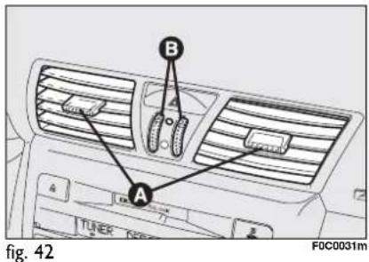
CENTRAL VENTS fig. 42
A - Controls for directing air flow (up/down, right/left).
B - Air flow adjusting controls:
● = completely closed
O = completely open.

REAR VENT fig. 43 (where provided)
A - Controls for directing air flow (up/down, right/left).
B - Air flow adjusting control:
● = completely closed
O = completely open.
Certain versions feature an oddment compartment instead of the rear vent.
HEATING AND VENTILATION
CONTROLS
A: Air temperature knob (mixing hot and cold air)
B: Heated rear window on/off button
C: Fan knob
D: Air recirculation on/off button
E: Air distribution knob.
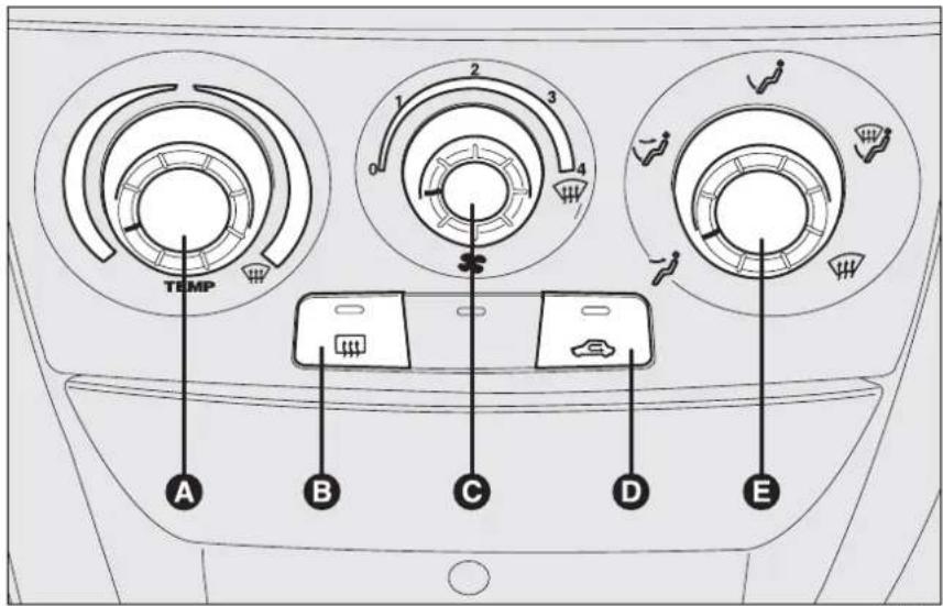
fig. 44
F0C0380m
WARMING THE PASSENGER COMPARTMENT
Proceed as follows:
☐ knob pointer A in the red section;
☐ knob pointer C on required speed;
□ turn the knob E to:
to warm the feet and at the same time demist the windscreen
to warm the feet and keep the face cool ("bilevel" function)
√ to warm the feet of the passengers in the front and rear seats
☐ air recirculation off (button led off).
FRONT WINDOW FAST DEMISTING/DEFROSTING
Proceed as follows:
□ rotate completely (pointer on ⏻)
knob A to the right;
□ turn knob C to ;
□ turn knob E to ;
☐ air recirculation off (button led off).
After demisting/defrosting use common controls to maintain the optimum conditions of visibility and comfort.
Window demisting
In the event of considerable outside moisture and/or rain and/or considerable differences in temperature inside and outside the passenger compartment, perform the following preventive demisting procedure:
☐ air recirculation off (button led off);
□ turn knob A to red section;
□ turn knob C to 2^nd speed;
□ turn knob E to 📌 or to √ if the windows do not demist.
HEATED REAR WINDOW AND DOOR MIRROR DEMISTING/DEFROSTING
Pressing button 📄 turns on this function which is shown by the turning on of the led on the button 📄.
This function is timed and switches off automatically after 20 minutes. To cut out this function press again button ....
IMPORTANT Do not apply stickers on the inside of the rear window over the heating filaments to avoid damage that might cause it to stop working properly.
FAN SPEED ADJUSTMENT
To ventilate the passenger's compartment properly, proceed as follows:
☐ Central and side vents: completely open;
□ Knob pointer A on blue section;
☐ knob pointer C on required speed;
□ Knob pointer E to 7;
☐ air recirculation off (button led off).
RECIRCULATION
Pressing button 📄 turns on this function which is shown by the turning on of the led on the button. This function is particularly useful when the outside air is heavily polluted (in a traffic jam, tunnel, etc.). However, it is better not to use it for long periods, especially if there are several people in the car.
IMPORTANT The inside air recirculation system makes it possible to reach the required “heating” or “cooling” conditions faster. Do not use the air recirculation function on rainy/cold days as it would considerably increase the possibility of the windows misting inside.
MANUAL CLIMATE CONTROL SYSTEM (where provided)
CONTROLS
A: Air temperature knob (mixing hot and cold air)
B: Heated rear window on/off button
C: Fan knob
D: Compressor on/off switch
E: Air recirculation on/off button
F: Air distribution knob.
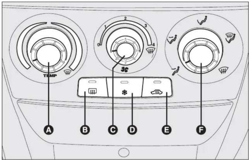
fig. 45
F0C0372m
WARMING THE PASSENGER COMPARTMENT
Proceed as follows:
☐ knob pointer A in the red section;
☐ knob pointer C on required speed;
□ turn knob F to:
to warm the feet and at the same time
demist the windscreen
√ to warm the feet and keep the face cool ("bilevel" function)
√ to warm the feet of the front and rear passengers.
☐ air recirculation off (button led off).
FRONT WINDOW FAST DEMISTING/DEFROSTING
Proceed as follows:
□ press button ✱;
□ rotate completely (pointer on 📌)
knob A to the right;
□ turn knob C to 🌐;
□ turn knob F to ;
☐ air recirculation off (button led off).
After demisting/defrosting use common controls to maintain the optimum conditions of visibility and comfort.
Window demisting
In the event of considerable outside moisture and/or rain and/or considerable differences in temperature inside and outside the passenger compartment, perform the following preventive demisting procedure:
□ press button *;
☐ air recirculation off (button led off);
□ turn knob A to red section;
□ turn knob C to 2^nd speed;
□ turn knob F to 📌 or to 🕒 if the windows do not demist.
Climate control system is very useful to speed up demisting since it dehumidifies the air. Set controls to demisting function and switch on the climate control system by pressing button ✉.
HEATED REAR WINDOW AND DOOR MIRROR DEMISTING/DEFROSTING
Pressing button 📄 turns on this function which is shown by the turning on of the led on the button 📄.
This function is timed and switches off automatically after 20 minutes. To cut out this function press again button 📄.
IMPORTANT Do not apply stickers on the inside of the rear window over the heating filaments to avoid damage that might cause it to stop working properly.
FAN SPEED ADJUSTMENT
To ventilate the passenger's compartment properly, proceed as follows:
☐ Central and side vents: completely open;
☐ Knob pointer A on blue section;
☐ knob pointer C on required speed;
□ Knob pointer F to ↗;
☐ air recirculation off (button led off).
[Non-Text]
[Non-Text]
[Non-Text]
[Non-Text]
[Non-Text]
[Non-Text]
[Non-Text]
[Non-Text]
[Non-Text]
[Non-Text]
[Non-Text]
[Non-Text]
[Non-Text]
[Non-Text]
[Non-Text]
[Non-Text]
[Non-Text]
[Non-Text]
AIR RECIRCULATION
Pressing button 📄 turns on this function which is shown by the turning on of the led on the button.
This function is particularly useful when the outside air is heavily polluted (in a traffic jam, tunnel, etc.) However, it is better not to use it for long periods, especially if there are several people in the car.
IMPORTANT The inside air recirculation system makes it possible to reach the required "heating" or "cooling" conditions faster. Do not use the air recirculation function on rainy/cold days as it would considerably increase the possibility of the windows misting inside.
CLIMATE CONTROL (cooling)
Proceed as follows:
□ Knob pointer A on blue section;
☐ knob pointer C on required speed;
□ Knob pointer F to ↗;
☐ Press buttons ✝ and 📄 (button leds on).
Cooling adjustment
Proceed as follows:
☐ Turn off button 📄 (button led off);
☐ Turn knob A to the right to raise temperature;
☐ Turn knob C to the left to reduce the fan speed.
LOOKING AFTER THE SYSTEM
During winter, the climate control system must be turned on at least once a month for about 10 minutes. Before summer, have the system checked at a Fiat Dealership.
AUTOMATIC TWO-ZONE CLIMATE CONTROL SYSTEM (where provided)
Description
The car is fitted with a two-zone climate control system which makes it possible to separately adjust the air temperature on the driver's side and on the passenger's side.
The system is fitted with the AQS function (Air Quality System) that turns on inside air recirculation automatically when it detects the presence of outside polluted air (for example when driving in the city, queues and tunnels).
CONTROLS
A: Button for selecting the system automatic mode (AUTO) and knob to adjust temperature on driver side
B: Air distribution selection button
C: Display showing climate control system data
D: Knob for adjusting fan speed
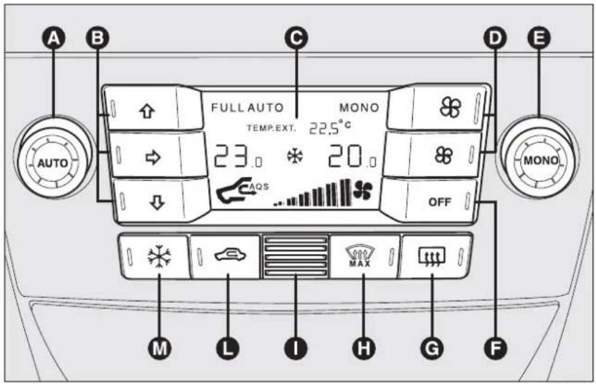
fig. 46
F0C0381m
E: Button for aligning the temperature set on the passenger's side with that on the driver's side (MONO) and knob to adjust temperature on passenger side
F: Two-zone climate control on/off button
G: Rear window heating on/off button
H: MAX-DEF function button (front window fast defrosting/demisting)
I: Passenger compartment temperature sensor
L: Inside air recirculation and AQS function on/off button
M: Climate control compressor on/off button
SWITCHING THE CLIMATE CONTROL SYSTEM ON
The system can be started in different ways, but it is advisable to set the temperatures required on the display; then press button AUTO.
It is possible to personalise required temperatures (driver and passenger) with a maximum difference of 7^ C.
The climate control system compressor works only with the engine running and outside temperature above 4^ C.
HOW TO USE THE AUTOMATIC FUNCTION (AUTO)
Press button AUTO; the system will automatically adjust:
□ air inlet in the passenger's compartment;
□ air distribution in the passenger's compartment;
thus cancelling all the previous manual adjustments.
When the climate control system is working automatically, FULL AUTO is displayed.
It is possible to personalise the choices made automatically by the system intervening manually on the following controls:
☐ fan speed adjustment knob;
☐ air distribution selection button;
□ inside air recirculation and AQS function on/off button;
□ climate control compressor button.

WARNING
It is inadvisable to use the inside air recirculation feature
with low outside temperature as the windows might mist over quickly.
FAN SPEED ADJUSTMENT
To adjust the fan speed, press button ✿.
The 12 selectable speeds are shown by the lighting up of the bars on the climate control system display:
The fan can be cut off (all bars off) only if the climate control compressor has been switched off pressing button ✦.
To restore automatic fan speed control, after a manual adjustment, press button AUTO.
FAST FRONT WINDOW DEMISTING/DEFROSTING (MAX-DEF function)
Pressing button # the climate control automatically activates timed operation of all the functions required to quicken demisting/defrosting of the windscreen and front side windows.
Functions are:
☐ switches on climate control compressor (if outside temperature exceeds 4^ C);
□ switches off inside air recirculation, if on (button led 📄 off);
□ switches on heated rear window (button led 📌 on) and door mirror coils;
□ sets max air temperature;
□ activates proper air flow.
HEATED REAR WINDOW AND DOOR MIRROR DEMISTING/DEFROSTING
Pressing button ☐ activates this function. When this function is on, the button led is on.
This function is timed.
IMPORTANT Press button 📄 to obtain outside air inlet into passenger compartment.
INSIDE AIR RECIRCULATION ON/OFF AND AQS FUNCTION (Air Quality System)
Press button
Inside air recirculation is controlled by three operating logics:
□ automatic control, indicated by message AQS on the display and button led off;
☐ forced switching off (inside air recirculation always off with air inlet from outside), button led 📄 off;
☐ forced switching on (inside air recirculation always on with air inlet from outside), button led 📄 on.
Pressing button OFF, the climate control system turns on automatically the inside air recirculation function (button led on). In these conditions it is however possible to take air from the outside (and vice versa) pressing button (button led off).
With button OFF pressed (button led on), the AQS (Air Quality System) function cannot be activated.
IMPORTANT The inside air recirculation system makes it possible to reach the required "heating" or "cooling" conditions faster. It is however inadvisable to use it on rainy/cold days as it would considerably increase the possibility of the windows misting inside, especially if the climate control system is off. It is advisable to turn on the inside air recirculation system in queues or tunnels to avoid admitting polluted air from outside. The prolonged use of this function should however be avoided, especially with several persons on board, to avoid the possibility of the windows misting inside.
AQS (Air Quality System) function activation
The AQS function, (message AQS on the display), turns on air recirculation automatically when it detects the presence of outside polluted air (for example when driving in the city, queues and tunnels).
IMPORTANT When the AQS function is active, after 15 minutes of consecutive internal air recirculation, the climate control system enables outside air inlet (regardless of air pollution level) for approx. 1 minute to change air inside the passenger compartment.
ALIGNMENT OF SET TEMPERATURES (MONO function)
Pressing button MONO automatically aligns the temperature on the passenger's side with that on the driver's side.
Turn the knob AUTO or MONO to raise/reduce the temperature between the two zones by the same value.
Press again button MONO to disable the function.
CLIMATE CONTROL COMPRESSOR ON/OFF
Press button ✦ to switch on the climate control compressor.
Compressor on
□ button led ✦ on;
□ symbol ✝ on the display, lit.
Compressor off
□ button led ✱ off;
□ symbol ✝ on the display, off;
□ inside air recirculation off;
☐ AQS function disabled.
With the climate control compressor off, it is not possible to admit air to the passenger compartment with a temperature below the outside temperature; in this case symbol ò flashes on the display.
The switching off of the climate control compressor remains in storage even when the engine has been stopped. To restore automatic control for switching on the climate control compressor, press button * or AUTO, in which case, the other manual settings set will be cancelled.
AIR DISTRIBUTION SELECTION
Pressing one or more buttons ↑/→/↓ it is possible to choose manually 7 of the possible air distributions to the passenger compartment:
Air flow to the windscreen and front side window vents to demist or defrost them.
Air flow towards the front and rear lower parts of the passenger compartment. This type of distribution allows heating of the passenger compartment in the shortest time.
Splitting of the air flow between front and rear vents, centre and side dashboard outlets, rear outlet, windscreen and front side window demisting vents.
Air flow to the dashboard centre and side outlets (passenger's body).

Splitting of the air flow between feet vents and windscreen and front side window demisting/defrosting vents. This type of air distribution allows satisfactory heating of the passenger compartment while preventing possible misting of the windows.

Splitting of the air flow between feet vents (warmest air) and the dashboard centre and side outlets and the rear outlet (coolest air).

Splitting of the air flow between centre and side dashboard outlets, rear outlet and windscreen and side window demisting/defrosting vents. This type of air distribution allows satisfactory ventilation of the passenger compartment while preventing possible misting of the windows.
IMPORTANT For operation of the climate control system, at least one of buttons // shall be activated. Deactivation of all buttons // is therefore not enabled by the system.
IMPORTANT To switch the system on again, press button OFF; this operation resets all operating conditions stored before switching off.
To restore automatic air distribution control after a manual selection, press button AUTO.
SWITCHING THE CLIMATE CONTROL SYSTEM OFF
Press button OFF.
The following information is displayed:
□ writing OFF;
□ outside temperature;
□ inside air recirculation on (button led on).
EXTERNAL LIGHTS
The left-hand stalk controls the external lights and the direction indicators.
The external lights can only be switched on when the ignition key is at MAR.
LIGHTS SWITCHED OFF fig. 47
Knurled ring turned to O.
SIDELIGHTS fig. 47
Turn the knurled ring to ⚙.
The warning light ≥00 on the instrument panel will turn on.
DIPPED BEAM HEADLIGHTS fig. 47
Turn the knurled ring to ≡D.
The warning light ≥00 on the instrument panel will turn on.
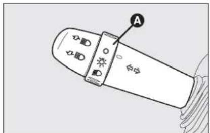
fig. 47
MAIN BEAM HEADLIGHTS fig. 47
When the knurled ring is at ☐ push the lever towards the dashboard (stable position).
The warning light ☑ on the instrument panel will turn on.
Pulling the lever towards the steering wheel again, the main beams are turned off and the dipped beams on.
FLASHING THE HEADLIGHTS fig. 47
Pull the lever towards the steering wheel (unstable position) regardless of the position of the knurled ring.
The warning light ☑ on the instrument panel will turn on.
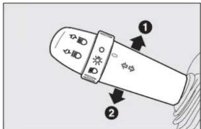
fig. 48
DIRECTION INDICATORS fig. 48
Push the lever to (stable) position:
☐ up (position I): right-hand direction indicator on
□ down (position 2): left-hand direction indicator on
Warning light ⇔ or ➔ will come on flashing on the instrument cluster at the same time.
Direction indicators are switched off automatically when the steering wheel is straightened.
If you want the indicator to flash briefly to show that you are about to change lane, move the stalk up or down without clicking into position (unstable position). When released the stalk will return to its home position.

natural_image
Diagram of a handheld device with control buttons and a light bulb, no text or symbols presentfig. 49
F0C0045m
"FOLLOW ME HOME" DEVICE fig. 49
This function allows the illumination of the space in front of the car for a preset period of time.
Activation
With the ignition key at STOP or removed, pull the stalk towards the steering wheel and operate it within 2 minutes from when the engine is turned off.
At each single movement of the stalk, the staying on of the lights is extended by 30 seconds up to a maximum of 2.5 minutes, then the lights are switched off automatically.
Each time the lever is operated, the warning light ≥0.0 turns on together with the message on the display (see “Warning lights and messages” section).
Deactivation
Keep the stalk pulled towards the steering wheel for more than 2 seconds.

natural_image
Illustration of a light bulb with a screen and control buttons, no text or symbols presentfig. 50
Activation
Turn the knurled ring to Ⓔ: in this way, the automatic activation of the side/tail-lights and dipped beam headlights are simultaneously enabled according to the external luminosity.
During the sensor operation lights can only be made flashing.
Deactivation
As a result of the sensor control, the main beam headlights will switch off and, after around 10 seconds, sidelights will switch off too.
The light sensor is not able to detect the fog presence, lights shall therefore be switched on manually.
AUTOMATIC HEADLIGHTS SENSOR (daylight sensor) fig. 50 (where provided)
It detects the changes of the external light intensity of the car according to the light sensitivity set: greater is the sensitivity, smaller is the amount of external light necessary to control the switching-on of the exterior headlights. The daylight sensor sensitivity can be adjusted with the “Setup menu” on the display.
WINDOW WASHING
WINDSCREEN WASHER/WIPER fig. 51
The device can only work when the ignition key is at MAR.
The right stalk can be moved to five different positions:
A: windscreen wiper off.
B: flick wipe.
With the stalk in position B, turning the knurled ring F four possible intermittent speeds are obtained:
= very slow intermittent
■ = slow intermittent.
■■ = intermittent medium.
■■■ = fast intermittent.
C: continuous slow;
D: continuous fast;
E: fast temporary (unstable position).
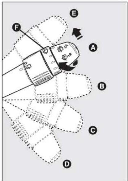
fig. 51
F0C0048m
Operation in position E is limited to the time the lever is held in this position. When the lever is released, it returns to position A automatically stopping the wiper.
IMPORTANT When the wiper is on, engaging reverse gear automatically turns on the rear window wiper.

Never use the window wiper to remove ice or snow from the windscreen. In these conditions, the wiper is submitted
to excessive effort that results in motor protection cutting in and wiper operation inhibition for few seconds as a consequence. If operation is not restored contact Fiat Dealership.

natural_image
Illustration of a handheld device with a hand holding it, showing internal components and a curved arrow indicating rotation (no text or symbols)"Smart washing" function fig. 52
Pulling the stalk towards the steering wheel (unstable position) operates the windscreen washer.
Keeping the stalk pulled, with just one movement it is possible to operate the washer jet and the wiper at the same time; indeed, the latter comes into action automatically if the stalk is pulled for more than half a second.
The wiper stops working a few strokes after releasing the stalk; a further "cleaning stroke", after a few seconds, completes the wiping operation.

natural_image
Technical line drawing of a car seatbelt component with labeled point A (no text or symbols beyond label)RAIN SENSOR (where provided)
The rain sensor A-fig. 53 is behind the driving mirror in contact with the windscreen and has the purpose of automatically adjust, during the intermittent operation, the frequency of the windscreen wiper strokes as to the rain intensity.
The sensor has a range of adjustment that gradually varies between wiper stationary (no wiping) when the windscreen is dry, to wiper at first continuous speed (continuous slow) with heavy rain.
Activation
Move the right-hand stalk downwards by one position.
The activation of the rain sensor is signalled by a control acquisition "stroke". IMPORTANT Keep clean the glass in the sensor area.
Turning the knurled ring F-fig. 51 it is possible to increase the sensitivity of the rain sensor, obtaining a quicker change from stationary (no wiping) when the windscreen is dry, to first continuous speed (continuous slow).
The increase of the sensitivity of the rain sensor is signalled by a control and acquisition "stroke".
Operating the windscreen washer with the rain sensor activated the normal washing cycle is performed at the end of which the rain sensor resumes its normal automatic function.
Deactivation
Turn the ignition key to STOP.
To the following starting operation (key at MAR), the sensor will not be reactivated even is the stalk is on B-fig. 51. In this event, to activate the rain sensor, you have to move the stalk to A or C and then again to B.
When the rain sensor is again activated in this way, at least one windscreen wiper stroke occurs, even if the windscreen is dry.
The rain sensor is able to recognize and automatically adjust itself in the presence of the following particular conditions:
☐ impurities on the controlled surface (salt, dirt, etc.);
☐ streaks of water caused by worn wiper blades;
□ difference between day and night.

In the event of ice on the windscreen, make sure to have disconnected the device.

WARNING
Make sure to have disconnected the device when the windscreen.

Do not activate the rain sensor when washing the car in an automatic washing station.

REAR WINDOW WASHER/ WIPER fig. 54
The device can only work when the ignition key is at MAR.
Pushing the stalk towards the dashboard (unstable position), the rear window washer jet and the continuous rear window wiper operation are activated.
Operation ends when the stalk is released.
Turning the knurled ring A from O to □ the rear window wiper with intermittent operation is activated.

natural_image
Line drawing of a car interior showing two views from front and side, with no visible text or symbolsHEADLIGHT WASHER fig. 55
Fiat Stilo headlight washers are "retractable", i.e.: they are located inside the front bumpers and they are activated (with dipped beam headlights and/or main beam headlights on) when the windscreen washer is operated.
IMPORTANT Check at regular intervals correct operation and cleanness of nozzles.

Never use the rear window wiper to remove ice or snow from the rear window. In these conditions, the wiper is submitted to excessive effort that results in motor protection cutting in and wiper operation inhibition for few seconds as a consequence. If operation is not restored contact Fiat Dealership.
CRUISE CONTROL (constant speed regulator) (where provided)
It is a device able to support the driver, with electronic control, which allows driving at speed over 30 km/h on long and straight dry roads (e.g.: motorways), at a desired speed, without pressing the accelerator pedal. Therefore it is not suggested to use this device on extra-urban roads with traffic. Do not use it in town.

DEVICE ENGAGEMENT
Turn knurled ring A-fig. 56 to ON.
The device may only be engaged in the 4^th or 5^th gear. Travelling downhill with the device engaged, the car speed may increase more than the memorised one.
When the device is activated, the warning light Ⓧ on the instrument panel turns on together with the message on the display (see section “Warning lights and messages”).
TO MEMORISE SPEED
Proceed as follows:
□ turn the knurled ring A-fig. 56 to ON and press the accelerator pedal to the required speed;
☐ turn the knurled ring B to (+) for at least three seconds, then release it. The car speed is memorised and it is therefore possible to release the accelerator pedal.
In the case of need (when overtaking for instance) acceleration is possible simply pressing the accelerator pedal: releasing the accelerator pedal, the car will return to the speed memorised previously.
TO RESET THE MEMORISED SPEED
If the device has been disengaged for example pressing the brake or clutch pedal, the memorised speed can be reset as follows:
□ accelerate gradually until reaching a speed approaching the one memorised;
☐ engage the gear selected at the time of speed memorising ( 4^th or 5^th gear);
□ press button C-fig. 56.
TO INCREASE THE MEMORISED SPEED
The speed memorised can be increased in two ways:
☐ pressing the accelerator and then memorising the new speed reached;
or
□ turning the knurled ring B-fig. 56 temporarily to (+).
Each turn of the knurled ring will correspond to a slight increase in speed (about 1 km/h), while keeping the knurled ring turned will correspond to a continuous speed increase.
TO REDUCE MEMORISED SPEED
The speed memorised can be increased in two ways:
☐ disengaging the device and then memorising the new speed;
or
□ keeping the knurled ring B-fig. 56 to (−) until reaching the new speed which will be memorised automatically.
Each turn of the knurled ring will correspond to a slight reduction in speed (about 1 km/h), while keeping the knurled ring turned will correspond to a continuous speed reduction.
DEVICE DISENGAGEMENT
Turn the knurled ring A-fig. 56 to OFF or the ignition key to STOP. The device is automatically deactivated also in one of the following cases:
□ pressing the brake or clutch pedal;
☐ ASR or ESP cut-in (where provided);
☐ gearshifting in versions with Selespeed automatic transmission (where provided);
☐ involuntarily moving the Selespeed lever (where provided) to N.

WARNING
When travelling with the device on, never set the gearshift lever to neutral and do not move the Selespeed lever to N.

WARNING
In the event of device malfunction or failure, turn the ring A-fig. 56 to OFF and a Fiat Dealership after check-protection fuse integrity.
CEILING LIGHTS
FRONT CEILING LIGHT fig. 57
Courtesy lights
Press button A to turn on/off the driver's courtesy light or button C to turn on/off the passenger's courtesy light.
With the key to STOP or removed, the ceiling light will stay on for about 15 minutes, then it is automatically switched off.

fig. 57

fig. 58
Central light
It turns on automatically when opening a door and it will turn off when closing the door, about 10 seconds later.
If the door is left open, the light goes off after about 3 minutes.
The bulb can also be turned on/off by pressing button B.
Light turning on/off is gradual.
After switching on by button B, if the key is at STOP or removed, the ceiling light stays on for about 15 minutes, then it is automatically switched off.
REAR CEILING LIGHT
(where provided) fig. 58
Versions without sunroof
Press button A to turn on/off the left rear light or button B to turn on/off the right rear light.
When the front ceiling light is on, also the rear ceiling light will come on.
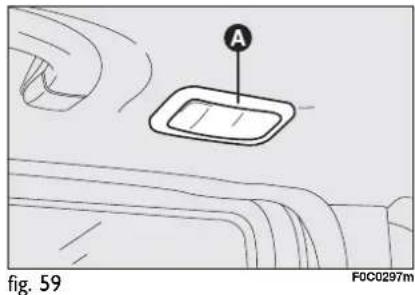
Versions with sunroof fig. 59
To turn on/off the bulbs, press the ceiling lights A, located on rear doors.
Ceiling lights turn on:
□ when a door is unlocked, and stay on for about 10 seconds if no door is opened;
□ when removing the key from the ignition switch, they stay on for about 10 seconds and then go off automatically;
☐ when fuel cut-off switch is activated, they stay on for about 15 minutes, and then go off automatically.
Door locking causes immediate light switching off.
CONTROLS
HAZARD LIGHTS fig. 60
They come on when switch A is pressed regardless of the position of the ignition key.
When the device is on, the switch flashes and warning lights ⇔ and ⇒ on the cluster come on.
Press the switch A again to turn the lights off.

WARNING
The use of hazard lights is governed by the Highway
Code of the country you are in. Keep to the rules.


FRONT FOG LIGHTS (where provided)
To turn front fog lights on, press button A-fig. 61 to activate these lights it is necessary to have the side/taillights switched on.
Press the button again to turn the lights off.
PARKING LIGHTS
These lights can only be turned on with ignition key at STOP or removed, by pressing button B-fig. 61 for about 1 second.
Press the button again to turn the light off.
REAR FOG LIGHTS
To turn rear fog lights on, press button C-fig. 61, to activate these lights it is necessary to have the dipped beams or front fog lights switched on.
Press the button again to turn the lights off.

natural_image
Technical illustration of a mechanical component with a labeled section (A), showing internal components and a close-up view of the base (no text or symbols present)fig. 62
FUEL CUT-OFF SWITCH fig. 62
It is located next to the passenger's door post, at the bottom, and comes into operation in the case of a crash:
☐ cutting off fuel and switching off the engine;
□ automatically unlocking the doors;
□ switching on interior lights (for about 15 minutes).
When the device comes into operation, the instrument panel warning light △ comes on together with the message on the display (see section "Warning lights and messages").
Carefully inspect the car to find fuel leaks, e.g. in the engine compartment, under the car or near the tank.
If no fuel leaks are found and the car can be started again, press button A to reset the fuel system and the lights.
After a crash, remember to turn the ignition key to STOP to prevent battery run-down.

WARNING
If, after a crash, you smell fuel or see leaks from the fuel system, do not reset the switch to avoid fine risk.
INTERIOR FITTINGS
FRONT ARMREST (where provided)
The armrest can be adjusted up and down.
To adjust, lift the armrest slightly and pull the release device B-fig. 63.
An oddment compartment can be found in the front armrest. Press button A to lift the cover.
IMPORTANT Raise the armrest completely to prevent interfering with the handbrake lever when operating it. When the armrest is fully raised, take care not to press button A accidentally to avoid opening the oddment compartment cover and the falling of the objects contained as a consequence.

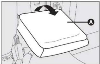
fig. 64
F0C0073m
REAR ARMREST (where provided)
To use the rear armrest A-fig. 64, lower it as shown in the figure.
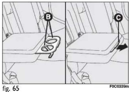
The armrest houses two compartments B-fig. 65 for glass and/or can holder. To use them pull the tab C in the arrow direction.
Inside the armrest, after lifting the cover, there is an oddment compartment.

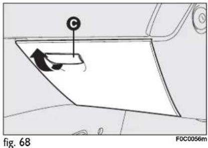

natural_image
Diagram of a vehicle seatbelt with directional arrows indicating movement (no text or symbols)
To open the vent operate lever B in the arrow direction.
If the two-zone climate control system is fitted, the temperature of this compartment will be the same as that on passenger side.
Lower oddment compartment on passenger's side
Open the oddment compartment moving the handle C-fig. 68, as shown by the arrow.
When the oddment compartment is opened, an interior courtesy light comes on. Such light stays on for about 15 minutes after having turned the key to STOP.
If during this time a door or the boot are opened, the light will come on again for about 15 minutes.
Oddment compartments under the seats (where provided) fig. 69
On certain versions, under the driver seat is fitted an oddment compartment; do not use it to put inside objects heavier than 1,5 kg.

WARNING
Never travel with the odd-ment compartments open to prevent risk of injuries in the event of a crash.

CURRENT OUTLET (12V)
The current outlet is located on the central console and it only works with ignition key at MAR. If the smokers' kit is requested, the current outlet will be replaced by the cigar lighter (see next paragraph).
CIGAR LIGHTER (where provided)
It is located on the central console, at the side of the handbrake lever.
Press button A-fig. 70 to switch on the cigar lighter with ignition key at MAR.
After few seconds the button will return to its initial position and is ready for use.
IMPORTANT Always check that the cigar lighter has turned off.

natural_image
Line drawing of a plastic waste bin with an open lid and internal trash inside (no text or symbols)IMPORTANT The cigar lighter gets very hot. Handle it with care and make sure that it is not used by children: danger of fire and/or burns.
ASHTRAY (where provided)
It consists of a spring-release removable plastic container fig. 71, that can be located in the glass/can holder recesses on the central console.
IMPORTANT Do not use the ashtray as waste paper basket: it might set on fire in contact with cigarette stubs.
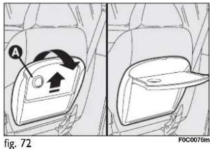
TILTING SHELF (where provided)
Behind the passenger seatback, it is available (on certain versions) a tilting shelf A-fig. 72.
To position it horizontally, pull it towards the direction shown by the arrows; reverse this operation to reposition it.
IMPORTANT Do not position on the tilting shelf objects heavier than 3 kg: for safety purposes the shelf is released from its housing when submitted to excessive loads.

Resetting the shelf (after releasing)
Proceed as follows:
☐ fit the shelf B-fig. 73 so that the support fixed pin A is fitted inside the shelf left rail;
□ turn the shelf B until the lower edge is touching the support A mobile pin C;
☐ press slightly in arrow direction to set the shelf B in the position of use. Pin C is inside the shelf right rail.
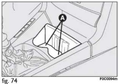

WARNING
Never travel with the shelf tilted. The shelf or the objects on it can cause injuries in the event of a crash.
GLASS HOLDER
The central console houses two recesses A-fig. 74 for glasses, cups or cans.

natural_image
Line drawing of a car interior with a highlighted seat and dashboard (no text or symbols)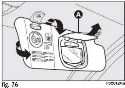
ODDMENT COMPARTMENT
fig. 75
It is located in the central console, under the front armrest.
SUN VISORS fig. 76
They are located at the sides of the driving mirror. They can be adjusted forwards and sidewards.
On certain versions, th passenger's sun vis- sor is fitted, on the back, with a courtesy mirror with a light which enables to use the mirror also with poor sunlight.
Lift the lid A to use the mirror.
When the ignition key is at STOP, the light stays on for about 15 minutes: if in this period a door or the tailgate is opened, the light will stay on for another 15 minutes.
The passenger's sun visor also carries the symbols and the message concerning the correct use of the child restraint system with passenger's air bag (for further information see paragraph "Front passenger's Air bag" in section "Safety").
"SKYWINDOW" (BLADE SUNROOF) (where provided)
This is a roof opening system consisting of 5 glass blades. The sunroof is equipped with a sun curtain electronically controlled, which has the function to prevent sun radiation.
SUNROOF OPENING
With ignition key at MAR turn knob A-fig. 77 clockwise and select one of the 6 opening positions.

Do not open the sunroof if there is snow or ice on it: it could be damaged.

To guarantee proper sunroof operation, routinely check that water drain ducts at sun-roof corners are clean; clean also gaskets and sliding guides (with a cloth soaked with water).


WARNING
When leaving the car, the ignition key should be removed to prevent the sunroof from being operated inadvertently and harming anyone remaining in the car. Improper use of the sunroof can be dangerous. Before and during its operation ensure that any passengers are not at risk from the moving roof either by personal objects getting caught in the mechanism or by being injured by it directly.

natural_image
Line drawing of a car's rear window with a lid labeled 'A' (no text or symbols beyond label)fig. 78
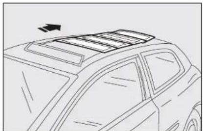
natural_image
Line drawing of a car's rear window with roof and side panel (no text or symbols)fig. 79
GLASS BLADES OPENING (knob turning clockwise)
With fully closed roof (curtain and blades), control knob A-fig. 77 at "0", glass blade opening affects the curtain opening as follows:
☐ First knob click: rotary movement of the first blade until reaching position A-fig. 78; the curtain slides lined up to the second blade.
☐ Second knob click: complete opening of the first blade and movement of the other ones towards the rear part fig. 79 together with movement of the sun curtain.
☐ Third knob click: glass blades ( 2^nd , 3^rd and 4^th ) moving backwards and movement of the sun curtain.
☐ Fourth knob click: glass blades ( 2^nd and 3^rd ) moving backwards and movement of the sun curtain.
☐ Fifth knob click: second blade moving backwards and movement of the sun curtain.
So the Skywindow is completely open.
With closed blades and sun curtain open
☐ First knob click: rotary movement of the first blade until reaching position A, and the sun curtain.
☐ Second knob click: complete opening of the first blade and the other blades moving backwards.
☐ Third knob click: glass blades ( 2^nd , 3^rd and 4^th ) moving backwards.
☐ Fourth knob click: glass blades ( 2^nd and 3^rd ) moving backwards.
☐ Fifth knob click: second blade moving backwards.
So the Skywindow is completely open.
To open the sunroof completely with one single operation, turn the knob to the last click (fifth).
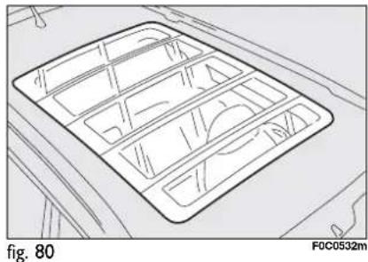
natural_image
Diagram of a vehicle interior layout with grid patterns and directional arrows, labeled 'fig. 80' (no text or symbols within the diagram itself)SUNROOF CLOSING
Glass blades closing (knob turning counterclockwise) fig. 80
With blades and curtain open (knob A-fig. 81 on fifth click), blades closing is not affecting the curtain.
☐ First knob click: second blade moving forwards.
☐ Second knob click: second blade moving forwards.
☐ Third knob click: second blade moving forwards.
☐ Fourth knob click: second blade moving forwards and first blade rotation until reaching the spoiler position.
☐ Fifth knob click: blades closing completely.
To close the sunroof completely with one single operation, turn the knob to "0".
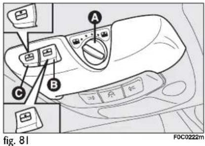
SUN CURTAIN OPENING/CLOSING
To open the curtain press button C- fig. 81.
Curtain opening can be stopped as follows:
□ pressing again the button C;
□ when reaching the required opening position, that can be as follows:
– with glass blades fully closed (equal to roof opening from passenger compartment)
– with glass blades open partially: lined up to the second blade
– with glass blades fully open: lined up to the second blade and covering the four open blades.
To close the curtain press button B-fig. 81.
Curtain closing depends on glass blades opening position: the sunshade curtain cannot be closed completely if blades are open.
Curtain closing can be stopped as follows:
□ pressing again button B;
□ when reaching the required opening position, that can be as follows:
– with glass blades fully closed (equal to roof opening from passenger compartment);
– with glass blades open partially: lined up to the second blade;
– with glass blades fully open: the curtain cannot be closed.
IMPORTANT Turning the ignition key to STOP after having operated one of buttons B-fig. 81 or C, the selected operation will be completed.
SUNROOF OPENING/CLOSING
With key without remote control (where provided)
Opening: turn the key clockwise in the door revolving plug.
Closing: turn the key counterclockwise in the door revolving plug.
With key with remote control
Opening: prolonged pressing (for more than 2 seconds) on button 🔒.
Closing: prolonged pressing (for more than 2 seconds) on button 🔒.
When buttons 🔒 /☐, are released, the above functions are cut-off.
When opening, blades and curtain open at the same time.
When closing, the curtain closes first and then are closed the blades.
The anti-crushing safety system fitted on the front curtain outline is active along the whole closing range of the curtain and cuts into operation when an obstacle (e.g.: finger, hand, etc...) is met. This safety device guarantees the reversal for a short section.
In addition, the anti-crushing safety system is active on the rear border of the first blade and on the front outline of the second blade: in this case it is active on the whole closing range of the curtain and cuts into operation when an obstacle (e.g.: finger, hand, etc...) is met. This safety device guarantees the reversal for a short section.
As concerns the first blade it is active on the whole rotation range and guarantees the reversal of the whole stroke.
After anti-crushing system activation, resetting can be carried out with the following 2 procedures:
☐ pushing knob A-fig. 83 upwards (reset previously stopped movement);
□ turning knob A to another position.
INITIALISATION PROCEDURE
Sunroof shall be re-initialised after disconnecting the battery or if the relevant protection fuse is blown:
□ turn knob A-fig. 81 to "0" (fully closed);
☐ keep the knob pressed for over 5 seconds: the sunroof will close jerkily;
☐ keep the knob pressed and wait for complete closing of the sunroof, until the sun curtain clicks twice.
Sunroof is now initialised and it shall work regularly. Otherwise, contact Fiat Dealership.
IMPORTANT Carry out the initialisation procedure with the engine running. If stopping the initialisation procedure before ending it, repeat it from the beginning.
Ice or other foreign matters in the sun-roof rails could cause anti-crushing repeated operation. Therefore make sure there is no obstacle.
In this case it is possible to inhibit the anti-crushing system by closing the roof (within 5 seconds from system activation), turning knob A-fig. 81 to 0 and keeping it pressed upwards until closing.
IMPORTANT During this operation do not release knob A; if releasing the knob and then pressing it again, it will be necessary to carry out the initialisation procedure described in the previous paragraph.
IMPORTANT During this operation the anti-crushing system is cut-out.
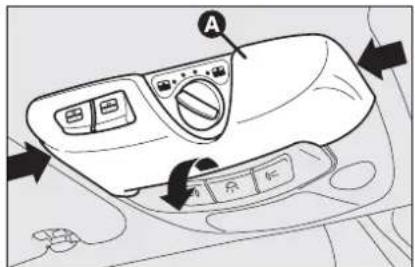
fig. 82
FOC0253m
EMERGENCY OPERATION
If the electrical control device does not work, the sunroof can be operated manually as follows:
□ remove the front ceiling light A-fig. 82 pressing on the sides of the plastic shape as shown by the arrow;
☐ insert the proper emergency key B-fig. 83 (located inside the ceiling light) into the seat C-fig. 84;
□ turn the key to open or close (according to the rotation direction) the glass blades.

natural_image
Technical line drawing of a mechanical assembly with labeled component B (no text or symbols present)fig. 83
FOC0400m
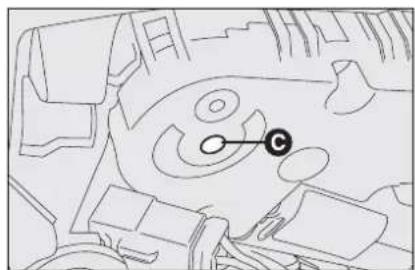
natural_image
Technical line drawing of a mechanical component with no visible text or symbolsfig. 84
F0C0399m
Then, carry out the initialisation procedure described on previous page.
DOORS
CENTRAL DOOR LOCKING SYSTEM
From the outside
With the doors closed, fit and turn the key in one of the front door locks.
From the inside
From inside the car (with doors closed) press the door lock/unlock button A-fig. 85 located on the driver's door control panel.
When operating the knob of a door, you lock only the interested door. Should power be lacking it is possible to open/close the doors manually.
IMPORTANT The rear doors cannot be opened from inside when the child lock is engaged.

fig. 85
FOC0142m
CHILD LOCK (5-door versions)
To prevent opening the rear doors from the inside.
This device fig. 86 can be engaged only with doors open:
□ position I - engaged (door locked);
□ position 2 - disengaged (door can be opened from the passenger's compartment).

fig. 86
F0C0061m
The device is engaged even if the doors are unlocked by the centralised system.
IMPORTANT Always use this device when transporting children.
IMPORTANT After engaging the lock, check by trying to open a rear door with the internal handle.
POWER WINDOWS
Power windows are fitted with anti-crushing safety device to detect the presence of an obstacle in the window closing stroke. If an obstacle is detected, the safety system will stop window closing and will reverse window stroke.
IMPORTANT In the event that the anti-crushing function is activated 5 times in only 1 minute, the system will automatically enter the “recovery” mode (self-protection). This conditions is pointed out by the fact that, in the closing phase, the window goes up in jerks.
So, it is necessary to carry out the system restore procedure, acting as follows:
□ open the windows;
or
□ turn the ignition key to STOP and then to MAR.
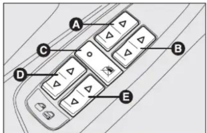
fig. 87
FIXJ063m
If no malfunction is present, the window returns to its normal operation automatically. In the event of failure make reference to section "Warning lights and messages".
IMPORTANT With the ignition key to STOP or removed, the power windows remain activated for about 2 minutes and are deactivated immediately the moment a door is opened.

WARNING
The system conforms to the forthcoming standard
2000/4/EC concerning the safety of passengers leaning out of the passenger compartment. At the same time, the upper outer gasket is not equipped with anti-crush protection in order to guarantee protection against unwanted access from outside the car.
CONTROLS
Driver side fig. 87
On the driver's door panel are set the buttons for controlling, with ignition key at MAR:
A: front left window opening/closing; window opening or closing in "automatic continuous" mode;
B: front right window opening/closing; window opening or closing in "automatic continuous" mode;
C: rear power window enabling/disabling controls;
D: rear left window opening/closing; "automatic continuous" operation just during window opening;
E: rear right window opening/closing; "automatic continuous" operation just during window opening.
Press buttons A or B to open/close the required window.
Pressing briefly one of the two buttons, the window "jerks", whereas a prolonged pressing makes the window opening or closing in "automatic continuous" mode.
When pressing again button A or B the window stops in the required position.

WARNING
Improper use of the power windows can be dangerous. Before and during its operation ensure that any passengers are not at risk from the moving glass either by personal objects getting caught in the mechanism or by being injured by it directly. Always remove the ignition key when getting out of the car to prevent the power windows being operated accidentally and constituting a danger to the passengers in the car.
BOOT
The boot tailgate (when unlocked) can be opened only from the outside through the electric opening handle under the shackle (saloon versions) fig. 88 or behind the shackle (Multi Wagon versions) fig. 89.
If doors are unlocked the boot can be opened at any time.
To open the tailgate use the key (with or without remote control).
If the boot is not shut properly the warning light ⊖ comes on together with the message on the display (see section "Warning lights and messages").
IMPORTANT With running car, never operate the tailgate shackle.

natural_image
Diagram showing a hand pressing down on a car's side panel with an arrow indicating the action (no text or symbols present)fig. 88
F0C0402m

natural_image
Line drawing of a car's rear bumper with a black arrow indicating a detail (no text or symbols)fig. 89
F0C0365m

natural_image
Diagram showing a car interior with a hand inserting a plug into the trunk, labeled as Fig. 90 (no text or symbols on diagram)OPENING FROM THE OUTSIDE
With key without remote control (where provided) fig. 90
Unlock the lock (where provided) with the metal insert in the ignition key.
Tailgate opening is facilitated by side gas shock springs.
Opening the boot tailgate, the interior boot ceiling light will come on: the bulb will automatically switch off closing the boot tailgate.
Such light will stay on for about 15 minutes after turning the key to STOP: if during this time a door or the boot are opened, the light will come on again for about 15 minutes.
With key with remote control
Press button 📄, even when the electronic alarm (where provided) is activated.
The tailgate opening is indicated by double flashing of direction indicators; closing is indicated by one flashing (only if alarm is on).
When opening the tailgate with the alarm on, it disconnects:
□ the volumetric protection;
□ the anti-raising protection;
□ the tailgate control sensor.
Such control functions are reset when closing the tailgate.
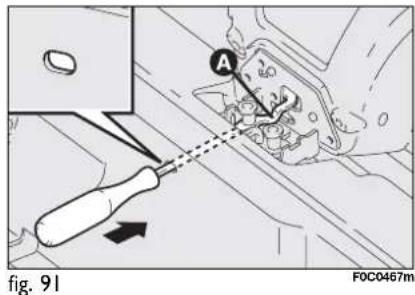
TAILGATE EMERGENCY OPENING FROM PASSENGER COMPARTMENT (Multi Wagon versions only)
In an emergency, the tailgate can be also opened from the passenger compartment; proceed as follows:
☐ take the screwdriver from the tool bag and fit it into the hole on the rear boot crossmember (see fig. 91);
☐ using the screwdriver, operate device A-fig. 91 to open the tailgate.

fig. 92
F0C0366m

natural_image
Line drawing of a car hood open showing the engine compartment (no text or symbols)fig. 93
F0C0414m
HEATED REAR WINDOW FLAP OPENING (where provided) (Multi Wagon versions)
Press button A-fig. 92: it is possible to open the heated rear window flap to gain access to the passenger compartment fig. 93.
TAILGATE CLOSING
To close, lower the tailgate until the lock clicks.

The addition of objects (speakers, spoilers, etc.) on the rear shelf or boot lid, except those envisaged by the manufacturer, may prevent the gas filled struts at the sides of the boot from working properly.

WARNING
When using the boot, make sure the loads you are carry-not exceed the permitted see section "Technical specs"). Also make sure the items not are arranged properly to them being thrown forwards or ring passengers should you imply.

WARNING
Never travel with objects on the rear shelf to prevent them being thrown forwards and injuring passengers in case of accident or sharp braking.
EXTENDING THE BOOT
The boot can be partially (1/3 or 2/3) or totally extended splitting the rear seat.
In Multi Wagon versions, remove the baggage cover following the instructions in paragraph "Baggage cover" to use the boot maximum loading volume.

natural_image
Line drawing of a car interior showing the rear seats and dashboard (no text or symbols)
natural_image
Line drawing of a car interior layout with no text or symbolsPartial extension (1/3 or 2/3) fig. 94-95
The boot extension to the right makes it possible to carry two passengers on the rear seat left-hand side.
The boot extension to the left makes it possible to carry one passenger on the rear seat right-hand side.

natural_image
Diagram showing car seatbelt buckle assembly with two black arrows indicating movement, no text or symbols presentVersions with fixed rear seat
Proceed as follows:
☐ lower completely the rear seat head restraints;
☐ move the seat belt sideways and check that the belt is not twisted;
☐ pull the handle in the middle of the cushion fig. 96, and tilt the required cushion;
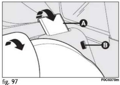
☐ lift seat back retaining lever A-fig. 97 and tilt the seat back forward. Lever lifting is shown by a "red band" B.

Versions with rear sliding seat (where provided)
Proceed as follows:
☐ lower completely the rear seat head restraints;
☐ move the seat belt sideways and check that the belt is not twisted;

☐ operate the lever B-fig. 98 and adjust the seat in the required position (e.g. completely forward if you want to obtain maximum boot extension);
☐ lift lever A and fold the seat back.
To extend the boot totally
The boot total extension makes it possible to use its maximum loading volume. Proceed as follows:
☐ for versions with rear sliding seat, fit seat belt buckles into the proper seats A-fig. 99;

☐ for versions with rear fixed seat, before folding the seat back, fit the seat belt tabs B-fig. 100 into the proper buckle C;
☐ lower completely the rear seat head restraints;
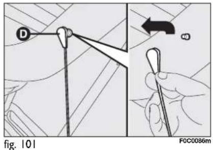
☐ move the seat belt sideways and check that the belt is not twisted;
☐ remove the rear parcel shelf and release the upper ends D-fig. 101 of the two tie rods by removing eyelets from the pins and pushing them in arrow direction
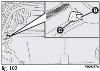
□ after tilting the cushion, fold completely rear seat backs (as described previously) to have one single surface.
☐ release shelf pins B-fig. 102 from their housings C and remove it.


For versions with rear fixed seat: remove the second shelf A-fig. 103 releasing pins from their housings B, lifting first the front part C-fig. 104 and then the rear part D from both sides. To refit it, reverse the above procedure.

For versions with rear sliding seat (where provided): remove the boot cover support A-fig. 105 pushing it from the bottom upwards, first one side and then the other one, until releasing it.

Lift seat back retaining lever A-fig. 106 set under the seat cushion (both on the right and on the left), and tilt them forward to obtain a single surface. Use lever A to adjust the seat back position.
Use lever B to adjust the space inside the boot.
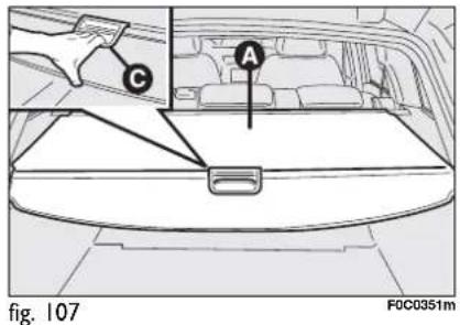
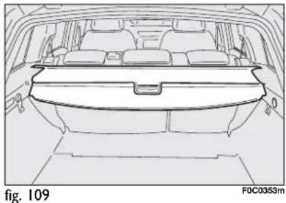
natural_image
Line drawing of a car rear view showing the roof, chassis, and seat compartments (no text or symbols)

natural_image
Technical line drawing of a car interior with two labeled parts (B), no text or symbols presentIt is possible to cover only half of the boot setting the cover as illustrated in figure 109.
Removing the boot cover
Roll the cover up to remove it and pull the two hooks A-fig. 110 towards the luggage compartment inside part (as shown by the arrows).
Then lift and remove the cover.
BOOT COVER
(Multi Wagon versions)
The boot cover A-fig. 107 can be rolled up and removed.
To roll it up remove the two rear pins B-fig. 108 from their housings.
IMPORTANT Guide the cover while rolling it up by holding its handle C-fig. 107.

To refit the cover, insert the reel ends in their housings and make sure the fastening hooks are well fastened. Now extend the cover by pulling its handles, as previously described, and hook the two rear pins B-fig. III.
IMPORTANT Do not put heavy objects on the cover which may seriously damage it.

WARNING
The objects put on the cover may be thrown forwards and injure passengers should you brake sharply or in the event of an accident.

TO RETURN THE REAR SEAT BACK TO ITS ORIGINAL POSITION
Move the seat belt sideways and check that the belt is not twisted.
Versions with rear fixed seat
Lift the seat backs and push them backward until both coupling mechanisms click in place, check that the "red band" B-fig. 112 at the side of levers A is no longer visible.
The "red band" B indicates missing seat back coupling.
Reposition the cushions in horizontal position keeping the centre seat belt tongue raised.

WARNING
Make sure the seat back is correctly hooked on both sides ("red bands" B-fig. 112 not visible) to prevent seat back being thrown forwards and injuring passengers should you brake sharply.
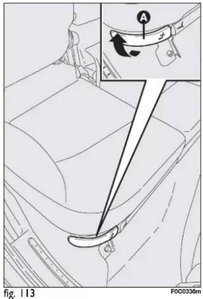
Versions with rear sliding seat (where provided)
Lift lever A-fig. 113 (right and left) and reposition the seat back in straight position.
Take out buckles from their housing to have them ready for use.

natural_image
Diagram showing a curved line with a black arrow pointing to a circular ring on a surface, labeled 'fig. 114' and 'FDC0034m' (no text or symbols on the diagram itself)ANCHORING THE LOAD
The boot houses 4 hooks (where provided) fig. 114 to which ropes can be attached which ensure that the load is properly secured.
IMPORTANT Never anchor to single hooks a load exceeding 100 kg.

WARNING
A heavy load that has not been secured may cause se- rm.

WARNING
If you want to carry reserve fuel in a can, follow law reg-
ulations, only using a certified can, suitably fastened to the load securing eyelets. Even in this way the risk of fire is increased in the case of an accident.

natural_image
Technical line drawing of a car rear compartment with internal compartments (no text or symbols)CARGO BOX (where provided) fig. 115
It consists of a special preformed box to be used for housing objects located in the boot of cars fitted with rear sliding seat that enables to obtain uniform loading surface.

SKI TUNNEL (where provided)
This can be used to carry long objects (e.g. skis), fitting them into the tunnel from the boot.
To access it:
☐ lower the rear armrest A-fig. 116;
☐ press handle B-fig. 117 and lower the flap. To close the flap pull tongue C.

IMPORTANT Always check that loads are anchored properly to prevent them being thrown against the passengers in case of accident or sharp braking.
BONNET
TO OPEN THE BONNET
Proceed as follows:
☐ pull lever A-fig. 118 in the direction of the arrow;
□ pull lever B-fig. 119 and lift the bon-net.
IMPORTANT Bonnet raising is aided by two side gas springs. Do not tamper with these springs and guide the bonnet while raising it.
IMPORTANT Before opening the bonnet, check that windscreen wiper arms are not lifted from the windscreen.

fig. 118
FOC0029m
TO CLOSE THE BONNET
Lower the bonnet at approx. 20 cm from the engine compartment and then let it drop, ensuring that it is fully closed and not just held in position by the safety catch. If the bonnet does not close properly do not push it down but open it again and repeat the above procedure. If the bonnet is not shut properly, the warning light ☐ comes on together with the message on the display (see section "Warning lights and messages").
IMPORTANT Always check that the bonnet is closed properly to avoid its opening while the car is travelling.
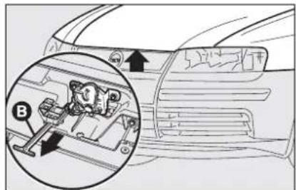
fig. 119
F0C0383m

WARNING
For safety reasons the bonnet must be closed properly at its opening while the car is g. Therefore, always check it rapidly closed and the catch en-Should you notice that the not perfectly engaged when g, stop the car immediately use the bonnet.

WARNING
This should only be done when the car is stationary.
ROOF RACK/ SKI RACK
The roof rack bars shall be secured to the roof in points shown A. Lift tabs B-fig. 120 using the screwdriver provided in the kit to access the seats C for securing the roof rack/ski rack.
A roof rack/ski rack specially designed for the car is available at Lineaccessori Fiat.
After few kilometers, check that fastening screws are firmly tightened.
IMPORTANT Never exceed the max. permissible loads (see section "Technical specifications").

fig. 120
Multi Wagon versions
The car is fitted with two longitudinal bars which can be used, by adding specific accessories, to carry various objects (e.g. skis, windsurf, etc...).
IMPORTANT Putting cross bars on longitudinal bars fig. 121 inhibits use of the sunroof (Skywindow) (where provided), since its opening interferes with the bars.

natural_image
Line drawing of a car front view showing the side panel and window (no text or symbols)fig. 121
IMPORTANT Never exceed the max. permissible loads (see section "Technical specifications").

WARNING
Open the tailgate with care when carrying objects on the k bars to prevent impacts.
HEADLIGHTS
ADJUSTING THE HEADLIGHT BEAM
Proper adjustment of the headlight beams is of vital importance for your safety and comfort and also for the other road users. To ensure you and other drivers have the best visibility conditions when travelling with the headlights on, the headlights must be set properly. Contact Fiat Dealership to have the headlights properly adjusted.
IMPORTANT When turning on gas discharge headlight lamps (where provided), it is normal that there should be a vertical movement of lenses, and consequently the same will also happen to the light beam, for the time required to achieve the correct headlight trim stabilisation, equal to approx. 2 seconds.

fig. 122
HEADLIGHT AIMING DEVICE
This device can be operated with the ignition key at MAR and dipped beams on. When the car is loaded, it slopes backwards. This means that the headlight beam rises. In this case, it is necessary to return it to the correct position.
To adjust the headlight slant
Press button A-fig. 122 located on the mask aside the steering wheel column; if the car is fitted with gas discharge headlights (xenon), slant adjustment is electronic and therefore button A is not present.
Press button A at arrow ▲ this will increase by one position, press the arrow ▼ on the button, this will lower by one position.
The display B-fig. 122 located on the instrument panel, provides the visual indication of the positions during the adjustment operation.
Correct positions as a function of the load
Position 0 - one or two passengers on front seats.
Position I - five passengers.
Position 2 - five passengers + load in the boot.
Position 3 - driver + maximum admitted load in the boot.
IMPORTANT Check beam aiming every time the load carried changes.
FRONT FOG LIGHT ADJUSTMENT
Contact Fiat Dealership to have the headlights properly adjusted.
HEADLIGHT BEAM ADJUSTMENT ABROAD
The dipped beam headlights are adjusted for circulation in the country in which the car is marketed. In countries with opposite circulation, to avoid glaring oncoming vehicles, it is necessary to cover the areas of the headlight using a special sticker tape provided for the purpose and available at Lineaccessori Fiat. Contact Fiat Dealership.
ABS SYSTEM
The car is fitted with ABS braking system, which prevents the wheels from locking when braking, makes the most of road grip and gives the best control when emergency braking under difficult road conditions.
System is completed by EBD (Electronic Braking Force Distribution), which distributes the braking action between front and rear wheels.
IMPORTANT To have the maximum efficiency of the braking system, it is necessary a setting period of about 500 km: during this period, it is better to avoid sharp, repeated and prolonged brakes.
ABS SYSTEM INTERVENTION
When the ABS cuts in, you will feel the brake pedal pulsating slightly and the system get noisier: it means that the speed should be altered to fit the type of road surface.
If the ABS system cuts in, it is a sign that the grip between tyre and the road surface has reached the limit: you must slow down to match the speed to the road grip available.

WARNING
If the ABS system cuts in it is a sign that the grip between the tyre and the road surface has reached the limit you must slow down to match the speed to the road grip available.

WARNING
The ABS exploits the tyre-road grip at the best, but it cannot improve it; you should therefore take every care when driving on slippery surfaces without taking unnecessary risks.

WARNING
When the ABS cuts in, and you feel the brake pedal pulsating, do not remove your foot, but keep it pressed; in doing so you will stop in the shortest amount of space possible under the current road conditions.
FAILURE INDICATIONS
ABS failure
ABS failure is indicated by the turning on of warning light (AES) on the instrument panel together with the dedicated message on the display (see section "Warning lights and messages"). In this case the braking system is still efficient, though without the aid of the ABS system. Drive carefully to the closest Fiat Dealership to have the system checked.

WARNING
If warning light Ⓑ comes on (together with the message on the display), stop the car immediately and contact the nearest Fiat Dealership. Fluid leaks from the hydraulic system, in fact, can compromise the braking system, both traditional systems and systems with ABS.
EBD failure
If the warning lights (ARD) and (!) (together with the message on the display) come on this indicates a fault in the EBD system (see section "Warning lights and messages").
In this case with sharp braking the rear wheels might lock too early, with the possibility of skidding. Drive extremely carefully to the nearest Fiat Dealership to have the system checked.
BRAKE ASSIST
(emergency braking assistance) (where provided)
The system, which cannot be cut out, recognizes emergency braking (on the ground of the brake pedal operation speed) and considerably increases the pressure in the braking circuit.
Brake Assist is deactivated on the versions equipped with ESP, in the event of ESP system failure (indicated by warning light Ⓐ) switching on together with the message on the display).
ESP SYSTEM (Electronic Stability Program) (where provided)
The ESP system is an electronic system controlling the car stability in the event of tyre grip loss.
The ESP system is therefore particularly useful when grip conditions of the road surfaces changes.
ABS SYSTEM INTERVENTION
It is signalled by the blinking of the warning light Ⓐ on the instrument panel, to inform the driver that the car is in critical stability and grip conditions.
The ESP system is automatically activated when the car is started and cannot be de-activated.

WARNING
Performance of the ESP system, in terms of active safety should not induce the driver to take pointless and unnecessary risks. The style of driving must in any case always be adapted to the conditions of the road surface, visibility an traffic. Road safety is always the driver's responsibility.
ESP SYSTEM INITIALISATION (after disconnecting the battery)
After reconnecting the battery, to restore regular operation of the ESP system, proceed as follows:
□ turn the ignition key to MAR;
□ turn the steering wheel 1/4 turn both clockwise and counterclockwise (to pass through position “straight wheels”);
□ turn the ignition key to STOP and then back to MAR.
A few seconds later the warning light will turn off; if it stays on contact Fiat Dealership.
These operations can also be performed with the engine on.
FAILURE INDICATIONS
In the event of failure, the ESP system is automatically disconnected and the warning light Ⓐ will turn on glowing steadily on the instrument panel, together with the message on the display (see section "Warning lights and messages"). In this case, go to a Fiat Dealership as soon as possible.

WARNING
During the use of the space-saver spare wheel, the ESP system carries on working. However, you must remind that the space-saver spare wheel has dimensions smaller than the standard tyre and therefore its grip is reduced as to the other car tyres.

WARNING
For correct operation of the ESP system, the tyres must absolutely be of the same brand and type on all wheels, in perfect conditions and, above all, of type, brand and size specified.
ASR SYSTEM
(Antislip Regulation)
It is an integral part of the ESP system, it controls car drive and cuts in automatically every time one or both driving wheels slip.
According to slipping conditions, two different control systems are activated:
☐ if the slipping involves both the driving wheels, the ASR function intervenes reducing the power transmitted by the engine;
☐ if the slipping involves only one driving wheel, the ASR system cuts in automatically braking the wheel that is slipping.
The action of the ASR is particularly helpful in the following circumstances:
☐ slipping of the inner wheel due to the effect of dynamic load changes or excessive acceleration;
□ too much power transmitted to the wheels also in relation to the conditions of the road surface;
□ acceleration on slippery, snowy or frozen surfaces;
☐ in the case of loss of grip on a wet surface (aquaplaning).
Switching on/off of the ASR system
The ASR system switches on automatically each time the engine is started.
Switching on/off is indicated by the relevant message on the display (see section "Warning lights and messages").

WARNING
The performance of the system, in terms of active safety should not induce the driver to take pointless and unnecessary risks. The style of driving must in any case always be adapted to the conditions of the road surface, visibility an traffic. Road safety is always the driver's responsibility.

F0C0066m
When travelling ASR can be switched off and on again pressing switch A-fig. 123 on the central console.
When the ASR is switched off this is shown by the lighting up of the led on the switch and by the relevant message on the display (see section "Warning lights and messages").
If the ASR is switched off when travelling, it will turn on again automatically the next time the engine is started.
When travelling on snowy roads with snow chains, it may be helpful to turn the ASR off: in fact, in these conditions, slipping of the driving wheels when moving off makes it possible to obtain better drive.
Failure indications
In the event of malfunctioning, the ASR system is automatically disconnected and the warning light Ⓐ will come on with fixed light on the instrument panel together with the message on the display (see section “Warning lights and messages”). In this case contact Fiat Dealership as soon as possible.

WARNING
When using the spare wheel, the ASR system is excluded
and the warning light (△) on the instrument panel turns on glowing steadily together with the message on the display (see section “Warning lights and messages”).

WARNING
For correct operation of the ASR system, the tyres must
absolutely be of the same brand and type on all wheels, in perfect conditions and, above all, of type, brand and size specified.
MSR system
(engine braking torque control)
The car is fitted with a special system, integral with the ASR system, that in case of sudden gear shifting, cuts in providing torque to the engine thus preventing excessive driving wheel drive that, specially in poor grip conditions, can lead to loss of stability.
EOBD SYSTEM
The EOBD system (European On Board Diagnosis) allows continuous diagnosis of the components of the car correlated with emissions.
It also alerts the driver, by turning on the warning light ☐ on the instrument panel (together with the message on the display) (see section “Warning lights and messages”), when these components are no longer in peak conditions.
The objective is:
☐ to keep the system efficiency under control;
□ warn when a fault causes emissions levels to increase;
□ warn of the need to replace deteriorated components.
The system also has a diagnostic connector that can be interfaced with appropriate tools, which makes it possible to read the error codes stored in the control unit, together with a series of specific parameters for engine operation and diagnosis. This check can also be carried out by the traffic police.
IMPORTANT After eliminating the inconvenience, to check the system completely, Fiat Dealerships are obliged to run a bench test and, if necessary, road tests which may also call for a long journey.

If turning the ignition key to MAR, the warning light does not turn on or if, while travelling it turns on glowing steadily or flashing (together with the message on the display), contact Fiat Dealership as soon as possible. Warning light operation can be checked by means of special equipment by traffic agents. Always comply with the traffic regulations in force in the country where you are travelling.
SOUND SYSTEM (where provided)
The Fiat Stilo sound system is of the fixed type: the instructions for use are given in the attached Supplement.
ACTUAL versions are provided with pre-setting for sound system with aerial, wiring and speakers.
To install the sound system, loosen screw A-fig. 124 and remove the oddment compartment, install the compartment provided with the sound system and the power cables for the electric connection.

IMPORTANT To guarantee proper sound and mechanical properties (e.g. water tightness and door soundproofing) at Lineaccessori Fiat is available a kit including an aerial adapter that improves AM frequency reception through the amplifier on the aerial support.
ACCESSORIES PURCHASED BY THE OWNER
If after buying the car, you decide to install electrical accessories that require a permanent electric supply (alarm, satellite antitheft system, etc.) or accessories that in any case burden the electric supply, contact Fiat Dealership, whose qualified personnel, besides suggesting the most suitable devices belonging to Lineaccessori Fiat, will also evaluate the overall electric absorption, checking whether the car's electric system is able to withstand the load required, or whether it needs to be integrated with a more powerful battery.

WARNING
Take care when fitting additional spoilers, alloy rims and
non-standard wheel caps: they might reduce ventilation of the brakes, thus their efficiency, during abrupt and repeated braking, or long downhill slopes. Make sure that nothing (mats, etc.) gets in the way of the pedals when they are pushed down.
INSTALLATION OF ELECTRIC/ELECTRONIC DEVICES
Electric/electronic devices installed after buying the car or in aftermarket shall bear the and marking:


Fiat Auto S.p.A. authorizes the installation of transceivers provided that installation is carried out at a specialized shop, work-manlike performed and in compliance with manufacturer's specifications.
IMPORTANT Installation of devices resulting in modifications of car characteristics may cause driving license seizing by traffic agents and also the lapse of the warranty as concerns defects due to the abovementioned modification or traceable back to it directly or indirectly.
Fiat Auto S.p.A. declines all responsibility for damages caused by the installation of non-genuine accessories or not recommended by Fiat Auto S.p.A. and installed not in compliance with the specified requirements.
RADIO TRANSMITTERS AND CELLULAR TELEPHONES
Mobile phones and other radio transceiver equipment (e.g.: HAM radio systems and the like) shall not be used inside the car unless a separate aerial is mounted.
IMPORTANT The use of mobile phones, HAM radio systems or other similar devices inside the passenger compartment (without separate aerial) may cause electronic systems equipping the car to malfunction. This could compromise safety in addition to constituting a potential hazard for the passengers.
In addition, transmission and reception of these devices may be affected by the shielding effect of the car body.
As concerns the use of mobile phones (GSM, GPRS, UMTS) with homologation, keep strictly to the mobile phone manufacturer's specifications.
"DUALDRIVE" ELECTRIC POWER STEERING SYSTEM
The car is provided with the electrically controlled power steering system called “Dualdrive” working only with ignition key at MAR and engine running, that can be customised by the driver according to the driving conditions.
IMPORTANT When turning quickly the ignition key, power steering full operation is obtained after 1-2 seconds.

fig. 125
FOC0065m
ACTIVATION/DEACTIVATION (CITY function)
To connect/disconnect the CITY function, push the button A-fig. 125 located on the central tunnel on the side of the gearbox control lever.
Connection of this function is reported by the word CITY on the “Multifunction display”.
When the CITY function is on the steering wheel effort is lighter and thus parking operations are easier: therefore this function is particularly useful for driving in city centres.
FAILURE INDICATIONS
Any failure is indicated by warning light coming on (together with the message on the display) (see section "Warning lights and messages").
In the event of electric power steering system failure, the car can be driven with mechanical steering.
IMPORTANT Under certain circumstances, factors independent from the electric power steering could cause the illumination of the warning light ☑ on the instrument panel. We suggest to stop immediately the car, turn off the engine for about 20 seconds and then re-start the car. If the warning light ☑ stays on (together with the message on the display), contact Fiat Dealership.
IMPORTANT The steering may become slightly stiff following parking manoeuvres including a great deal of steering. This is normal and caused by a system to prevent motor overheating. No servicing is required. The electrical power steering system will return to normal operation the next time the car is used.

WARNING
It is absolutely forbidden to carry out whatever after-
market operation involving steering system or steering column modifications (e.g.: installation of anti-theft device) that could badly affect performance and safety, cause the lapse of warranty and also result in non-compliance of the car with homologation requirements.

WARNING
Always switch the engine off, remove the key from the
starting device and actuate the steering lock before carrying out any maintenance operation, especially when the wheels are raised from the ground. In case this is not possible (e.g. when the key must be in MAR position or the engine running), remove the electric power steering main fuse before carrying out any maintenance operation.
PARKING SENSORS (where provided)
Parking sensors are located in the rear bumper fig. 126 (saloon versions) and fig. 127 (Multi Wagon versions) and their function is to inform the driver, through an intermittent buzzer, about the presence of obstacles behind the car.
ACTIVATION
Sensors are automatically activated when the reverse gear is engaged.
As the distance from the obstacle behind the car decreases, the acoustic alarm becomes more frequent.
BUZZER WARNINGS
When the reverse gear is engaged an intermittent acoustic signal is automatically activated.
The acoustic signal:
□ becomes louder as the reduction of distance between the car and the obstacle decreases;
□ becomes continuous when the distance between the car and the obstacle is less that 30 cm and stops immediately if the distance raises.
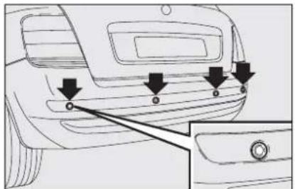
natural_image
Line drawing of a car's rear bumper with arrows pointing to specific points (no text or symbols)fig. 126
FOC0301m

natural_image
Technical line drawing of a car rear bumper with mounting points and arrows indicating features (no text or symbols)fig. 127
F0C0364m
☐ is constant if the distance is unvaried. If this situation takes place for side sensors, the signal is stopped after about 3 seconds to prevent sound indications when performing manoeuvres near walls.
Detection distances
Central action radius ....150 cm
Side action radius 60 cm
If several obstacles are detected, the control unit indicates the nearest one.
FAILURE INDICATIONS
In the event of sensor failures, when engaging the reverse gear the driver is warned by the turning on of warning light △ on the instrument panel and by the relevant message on the display (see section "Warning lights and messages").
Parking sensor operation is deactivated automatically when the trailer electric cable plug is fitted into the car tow hook socket.
Sensors are reactivated when removing the trailer cable plug.

For proper operation, the parking sensors set on the bumpers shall be clean from mud, dirt, snow or ice. When cleaning the sensors, take the utmost care to prevent their damaging; do not use therefore dry or rough clothes. Sensors shall be washed with clean water and car detergent, if required. In washing stations, clean sensors quickly keeping the vapour jet/high pressure washing nozzles at 10 cm at least from the sensors.

WARNING
Parking manoeuvres however are always under the driver's responsibility that shall always check the absence of people (specially children) or animals in the manoeuvre space. This system is just a help for the driver but she/he shall never reduce attention during dangerous manoeuvres even if performed at low speed.
GENERAL WARNINGS
☐ When parking, take the utmost care to obstacles set above or under the sensors.
☐ Objects set close to the car front or rear part, under certain circumstances are not detected and could therefore cause damages to the car.
☐ Indications sent by the sensors can be altered by dirt, snow or ice deposited on the sensors or by ultrasound systems (e.g.: truck pneumatic brakes or pneumatic hammers) set nearby the car.
AT THE FILLING STATION
PETROL ENGINES
Use only unleaded petrol.
To prevent errors, the diameter of the fuel tank filler is too small to introduce a lead petrol pump filler. Use petrol with a rated octane number (R.O.N.) not lower than 95.
IMPORTANT An inefficient catalyst leads to harmful exhaust emissions, thus contributing to air pollution.
IMPORTANT Never use leaded petrol, even in small amount or in an emergency, as this would damage the catalyst beyond repair.
DIESEL ENGINES
If the outside temperature is very low, the diesel thickens due to the formation of paraffins and could clog the diesel fuel filter.
In order to avoid these problems, different types of diesel are distributed according to the season: summer type, winter type arctic type (mountains/cold areas).
If refuelling with diesel fuel not suitable for the current temperature, mix diesel fuel with TUTELA DIESEL ART additive in the proportions stated on the can, putting first the antifreeze in the tank and then the diesel fuel.
Refuel with local diesel fuel if the car is used/parked in the mountains or in cold areas for a long period. In this event you are recommended to keep an amount of fuel higher than 50% in the tank.

The car must only be filled with diesel fuel for motor vehicles, in compliance with European Specification EN590.
The use of other products or mixtures may irreparably damage the engine with invalidation of the warranty due to the damage caused. In the event of accidentally filling with another type of fuel, do not start the engine and empty the tank. If the engine has been run even for only a very short time, in addition to the tank, it is also necessary to drain out the whole fuel circuit.
REFUELLING
To guarantee full tank filling, carry out two refuelling operations after the first click of the fuel delivery gun. Avoid further topping up operations that could cause damages to the fuel system.

FUEL FILLER CAP fig. 128
The fuel filler cap A is fitted with an antiloss device B which fastens it to the lid C so it cannot be mislaid.
To slacken the cap, turn it counterclockwise and remove it.
The cap A is fitted with key-lock: open the lid C then, turn the ignition key in the lock and open the cap.
When refuelling, secure the cap to the device inside the lid as shown in the figure.
IMPORTANT The sealing of the tank may cause light pressurising in the tank. A little breathing off, while slackening the cap, is absolutely normal.
After refuelling, turn the cap clockwise until it clicks, then turn the key clockwise, remove it and close the flap.

WARNING
Do not put naked flames or lighted cigarettes near the
fuel filler hole as there is a danger of fire. Do not bend too close to the hole either so as not to breathe in harmful vapours.

FUEL LID EMERGENCY OPENINGS
Saloon versions
Open flap A-fig. 129 set on the right side of the boot and pull the string located inside the flap.

Multi Wagon versions
Proceed as follows:
□ turn the knob A-fig. 130 and open the flap B set on the right side of the boot;
☐ hold the tongue C-fig. 131 to open the second flap D;

□ pull the string E located inside the flap.
PROTECTING THE ENVIRONMENT
The devices for curtailing petrol engine emissions are the following:
□ three-way catalytic converter;
□ Lambda sensors;
☐ fuel evaporation system.
In addition, do not let the engine run, even for a test, with one or more spark plugs disconnected.
The devices for curtailing diesel fuel engine emissions are the following:
□ oxidising catalytic converter;
□ exhaust gas recirculation system (E.G.R.);
□ Lambda sensors;
□ diesel particulate filter (DPF) (where provided it is fitted instead of the Lambda sensor).
DIESEL PARTICULATE FILTER (DPF) (where provided)
The Diesel Particulate Filter is a mechanical filter, integral with the exhaust system, that physically traps particulates present in the exhaust gases of Diesel engines.
The diesel particular filter has been adopted to eliminate almost totally particulates in compliance with current / future law regulations.
During normal use of the car, the engine control unit records a set of data (e.g.: travel time, type of route, temperatures, etc.) and it will then calculate how much particulates has been trapped by the filter.
Since this filter physically traps particulates, it shall be cleaned (reclaimed) at regular intervals by burning carbon particles. Reclaiming procedure is controlled automatically by the engine control unit according to the filter conditions and the conditions of use of the car. During reclaiming the following phenomena could take place: idling slight increase, fan activation, slight smoke increase, high exhaust temperatures. These situations shall not be considered as faults and they do not affect car performance and environment.
Diesel Particulate Filter clogged
If the dedicated message is displayed, refer to section "Warning lights and messages".

WARNING
During normal service the catalyst and the diesel particulate filter (DPF) reach high temperatures. Do not therefore park the car over inflammable materials (grass, dry leaves, pine needles, etc.): fire hazard.
SAFETY DEVICES
SEAT BELTS 110
PRETENSIONERS 113
CARRYING CHILDREN SAFELY.... 116
PRESETTING FOR MOUNTING THE "ISOFIX TYPE" CHILD RESTRAINT SYSTEM .... 121
PRESETTING FOR MOUNTING THE "UNIVERSAL ISOFIX" CHILD RESTRAINT SYSTEM .. 124
FRONT AIR BAGS 126
SIDE AIR BAGS (Side bag - Window bag) 130
SEAT BELTS
USING THE SEAT BELTS
The belt should be worn keeping the chest straight and rested against the seat back.
To fasten the seat belts, take hold the tongue A-fig. I and insert it into the buckle B, until hearing the locking click.
At removal, if it jams, let it rewind for a short stretch, then pull it out again without jerking.
To unfasten the seat belts, press button C. Guide the seat belt with your hand while it is rewinding, to prevent it from twisting.
Through the reel, the belt automatically adapts to the body of the passenger wearing it, allowing freedom of movement.

fig. 1
When the car is parked on a steep slope the reel mechanism may block; this is normal. The reel mechanism prevents the webbing coming out when it is jerked or if the car brakes sharply, in a collision or when cornering at high speed.
The rear seat is fitted with inertial seat belts with three anchor points and reel for the side and centre seats.

natural_image
Diagram of three human silhouettes with curved arms, no text or symbols presentfig. 2
Rear seat belts shall be worn as shown in fig. 2

WARNING
Never press button C-fig. I when travelling.
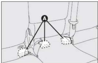
fig. 3
F0C0433m
When reclining the rear seat backs, to put the seat buckles back properly, use the suitable housings A-fig. 3 obtained in the cushion.
Take out buckles from their housings (versions with rear sliding seat) when resetting the seat in straight position, to have them ready for use.

fig. 4
IMPORTANT When the seat back is coupled properly, the "red band" B-fig. 4 present aside lever A disappears. The "red band" actually indicates improper seat back coupling. As concerns versions fitted with sliding seat, always check that the back is locked in proper position; these versions are fitted with reclining seat: when resetting it in proper position, make sure to hear the locking click.
IMPORTANT Remember that in the event of a violent collision, back seat passengers not wearing seat belts also represent a serious danger for the front seat passengers.
IMPORTANT After putting the seats back to their travelling position, restore the seat belt position to make them ready for use.

WARNING
Make sure the seat back is correctly hooked on both sides ("red bands" B-fig. 4 not visible) to prevent seat back being thrown forwards and injuring passengers should you brake sharply.
S.B.R. SYSTEM
The car is fitted with the S.B.R. system (Seat Belt Reminder), consisting of a buzzer which, together with the blinking of warning light on the instrument panel, warns the driver to fasten the seat belt.
The buzzer can be deactivated temporarily (until next engine stop) by the following procedure, to be carried out within 1 minute from turning the ignition key to MAR:
□ fasten the driver's seat belt.
□ wait for over 20 seconds and then release the driver's seat belt.
For permanent deactivation, contact Fiat Dealership.
The S.B.R. system can only be reset through the set-up menu (see section "Warning lights and messages" at paragraph "Seat belts not fastened").

fig. 5
FRONT SEAT BELT HEIGHT ADJUSTMENT
Four different adjustments in height are provided.
To adjust, press button A-fig. 5 and lower or raise the grip B.
Always adjust the height of the seat belt to fit the person wearing it. This precaution could greatly reduce the risk of injury in case of collision.
Correct adjustment is obtained when the belt passes half way between the end of the shoulder and the neck.

WARNING
Make the height adjustment when the car is stationary.

WARNING
After adjustment, always check that the slider is anchored in one of the positions provided. To do this, with the button A-fig. 5 released, exert a further pressure to allow the anchor device to catch if release did not take place at one of the preset position.
PRETENSIONERS
To increase the efficiency of the front and rear (where provided) seat belts, the car is fitted with pretensioners. These devices, in the event of violent front crash, rewind the seat belts a few centimetres. In this way they ensure that the seat belt adheres perfectly to the wearer before the restraining action begins. The seat belt locks to indicate that the device has intervened; the seat belt cannot be drawn back up even when guiding it manually.
IMPORTANT To obtain the highest degree of protection from the action of the pretensioning device, wear the seat belt keeping it firmly close to the chest and pelvis.
Front seat pretensioners activate only if front seat belts are properly fitted into buckles. A small amount of smoke may be produced. This smoke is in no way toxic and presents no fire hazard.
The pretensioner does not require any maintenance or greasing. Anything that modifies its original conditions invalidates its efficiency. If due to unusual natural events (floods, seas storm, etc.) the device has been affected by water and mud, it must necessarily be replaced.

WARNING
The pretensioner can only be used once. After a collision that has triggered it, have it replaced at a Fiat Dealership. Pretensioner validity is written on the label inside the lower oddment compartment. Pretensioners should be replaced at Fiat Dealership as this date approaches.

Operations which lead to knocks, vibrations or localised heating (over 100°C for a maximum of 6 hours) in the area around the pretensioners may cause damage or trigger them. These devices are not affected by vibrations caused by irregularities of the road surface or low obstacles such as kerbs, etc. Contact a Fiat Dealership for any assistance.
LOAD LIMITERS
To increase passenger's safety, the front and rear (where provided) seat belt reels contain a load limiter which allows controlled sag in such a way as to dose the force acting on the shoulders during the belt restraining action in case of front crash.

natural_image
Line drawing of two seated individuals in a seat, viewed from the side (no text or symbols)GENERAL INSTRUCTIONS FOR USING THE SEAT BELTS
The driver must comply with (and have the car occupants follow) all the local legal regulations concerning the use of seat belts. Always fasten the seat belts before starting.
Seat belts are also to be worn by expectant mothers: the risk of injury in the case of accident is greatly reduced for them and the unborn child if they are wearing a seat belt. Of course they must position the lower part of the belt very low down so that it passes under the abdomen (as illustrated in fig. 6).
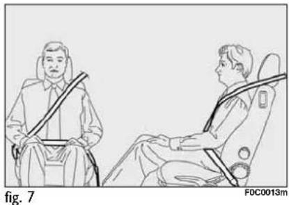
natural_image
Line drawing of two individuals seated in car seat positions, viewed from the side (no text or symbols)IMPORTANT The belt should not be twisted. The upper part should pass over the shoulder and cross the chest diagonally. The lower part should adhere to the pelvis (as shown in fig. 7) and not the abdomen of the passenger. Do not use any objects (pegs, stoppers, etc.) to keep the belts away from the body.

WARNING
For maximum safety, keep the back of your seat up-
right, lean back into it and make sure the seat belt fits closely across your chest and hips. Make sure that the seat belts of the front and rear passengers are fastened at all times! You increase the risk of serious injury or death in a collision if you travel with the belts unfastened.
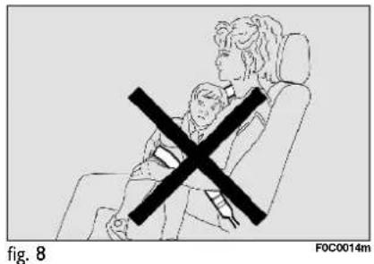
IMPORTANT Never travel with a child sitting on the passenger's lap with a single belt to protect them both fig. 8. Do not fasten other objects to the body.

WARNING
Under no circumstances should the components of the
seat belts and pretensioners be tam- pered with or removed. Any operation should be carried out by qualified and authorised personnel. Always contact a Fiat Dealership.

WARNING
If the belt has been subjected to heavy stress, for ex-
ample after an accident, it should be changed completely together with the anchors, anchor fastening screws and the pretensioners. In fact, even if the belt has no visible defects, it could have lost its resilience.
HOW TO KEEP THE SEAT BELTS ALWAYS IN EFFICIENT CONDITIONS
Observe the following:
□ always use the belt with the tap taut and never twisted; make sure that it is free to run without impediments;
□ after a serious accident, replace the belt being worn at that time, even if it does not appear damaged. Always replace the seat belts if pretensioners have been activated;
☐ to clean the belts, wash by hand with neutral soap, rinse and leave to dry in the shade. Never use strong detergents, bleach or dyes or other chemical substance that might weaken the fibres;
☐ prevent the reels from getting wet: their correct operation is only guaranteed if water does not get inside;
□ replace the seat belt when showing significant wear or cut signs.
CARRYING CHILDREN SAFELY
For optimal protection in the event of a crash, all passengers must be seated and wearing adequate restraint systems.
This is even more important for children.
This prescription is compulsory in all EC countries according to EC Directive 2003/20/EC.
Compared with adults, their head is proportionally larger and heavier than the rest of the body, while the muscles and bone structure are not completely developed. Therefore, correct restraint systems are necessary, other than adult seat belts.
The results of research on the best child restraint systems are contained in the European Standard EEC-R44. This Standard enforces the use of restraint systems classified in five groups:
Group 0 0-10 kg in weight
Group 0+ 0-13 kg in weight
Group 1 9-18 kg in weight
Group 2 15-25 kg in weight
Group 3 22-36 kg in weight
As it may be noted, the groups overlap partly and in fact, in commerce it is possible to find devices that cover more than one weight group.
All restraint devices must bear the certification data, together with the control brand, on a solidly fixed label which must absolutely never be removed.
Over 1.50 m in height, from the point of view of restraint systems, children are considered as adults and wear the seat belts normally.
Lineaccessori Fiat offers seats for each weight group, which are the recommended choice, as they have been designed and experimented specifically for Fiat cars.

WARNING
SERIOUS DANGER: Never place cradle child's seats facing backwards on the front passenger seat of cars fitted with passenger's air bag since
the air bag activation could cause serious injuries, even mortal. You are advised to carry children always on the rear seat, as this is the most protected position in the case of a crash. In any case, children's seats must absolutely not be fitted on the front seat of cars with passenger's air bag, which during inflation could cause serious injury, even mortal, regardless of the seriousness of the crash that triggered it. Children may be placed on the front seat of cars fitted with passenger's air bag deactivation. In this case, it is absolutely necessary to check the warning light ☐ on the instrument panel, to make sure that deactivation has actually taken place (see paragraph "Front passenger air bag" at paragraph "Front air bags"). The front passenger seat shall be adjusted in the most backward position to prevent any contact between child's seat and dashboard.
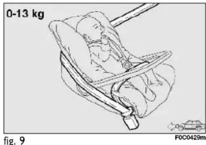
natural_image
Illustration of a baby in a car seatbelt, labeled 0-13 kg and F0C0429m (no text or symbols on the diagram itself)GROUP 0 and 0+
Babies up to 13 kg must be carried facing backwards on a cradle seat, which, supporting the head, does not induce stress on the neck in the event of sharp deceleration.
The cradle is restrained by the car seat belts, as shown in fig. 9 and in turn it must restrain the child with its own belts.
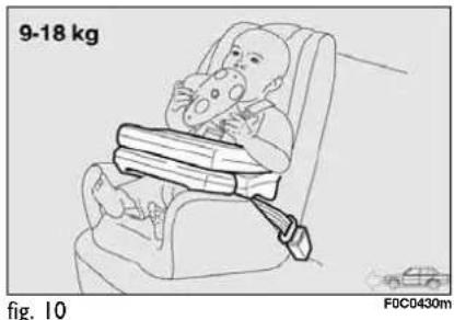
natural_image
Illustration of a baby sitting in a car seat with a bandage, no text or symbols presentGROUP I
Starting from 9 kg to 18 kg in weight, children may be carried facing forwards, with seat fitted with front cushion, through which the car seat belt restrains both child and seat fig. 10.

WARNING
The figure is only an example for mounting. Attain to the instructions for fastening which must be enclosed with the specific child restraining system you are using.

WARNING
Seats exist which are suitable for covering weight groups 0 and 1 with a rear connection to the car belts and their own belts to restrain the child. Due to their size, they can be dangerous if installed incorrectly fastened to the car belts with a cushion. Carefully follow the instructions for installation provided with the seat.

GROUP 2
Starting from 15 kg to 25 kg in weight, children may be restrained directly by the car belts fig. 11. The only function of the seat is to position the child correctly in relation to the belts, so that the diagonal part adheres to the chest and not to the neck and that the horizontal part clings to the child's pelvis and not the abdomen.

GROUP 3
For children from 22 kg to 36 kg the size of the child's chest no longer requires a support to space the child's back from the seat back.
Fig. 12 shows proper child seat positioning on the rear seat.
Children taller than 1.50 m can wear seat belts like adults.

WARNING
Figures are only an example for mounting. Attain to the ons for fastening which must used with the specific child re-g system you are using.
PASSENGER SEAT COMPLIANCE WITH REGULATIONS ON CHILD'S SEAT USE
Your car complies with the new European Directive 2000/3/EC regulating child's seat assembling on the different car seats according to the following tables:
3/5-door version, double rear seat
| Group Range of weight Front passenger Rear passenger Central passenger | ||
| Group 0, 0+ up to 13 kg U U U | ||
| Group 1 9-18 kg U U U | ||
| Group 2 15-25 kg U U U | ||
| Group 3 22-36 kg U U U | ||
5-door version, rear sliding seat
| Group Range of weight | SEAT | ||||
| Front passenger | LH side rear passenger | RH side rear passenger | Central passenger | ||
| Group 0, 0+ up to 13 kg U | U | LL | |||
| Group 1 9-18 kg | U | U | LL | ||
| Group 2 | 15-25 kg | U | U | L | L |
| Group 3 | 22-36 kg | U | U | L | L |
Key:
U = suitable for child restraint systems of the "Universal" category, according to European Standard EEC-R44 for the specified "Groups". L = suitable for certain child's restraint systems available at Lineaccessori Fiat for the specified group.
Below is a summary of the rules of safety to be followed for carrying children:
☐ The recommended position for installing children's seat is on the rear seat, as it is the most protected in the case of a crash.
If the passenger's air bag is deactivated always check the warning light 📋 on the instrument panel to make sure that it has actually been deactivated.
☐ Attain to the instructions for fastening the specific child restraint system which you are using. These instructions must be provided by the manufacturer. Keep the child restraint system installation instructions with the car documents and this Handbook. Never use a child restraint system without installation instructions.
□ Always check the seat belt is well fastened by pulling the webbing.
☐ Only one child is to be strapped to each retaining system.
□ Always check the seat belts do not fit around the child's throat.
☐ While travelling, do not let the child sit incorrectly or release the belts.
☐ Passengers should never carry children on their laps. No-one, however strong they are, can hold a child in the event of a crash.
☐ In case of an accident, replace the seat with a new one.

WARNING
Never place cradle child's seats facing backwards on
the front passenger seat of cars fitted with passenger air bag since the air bag activation could cause serious injuries, even mortal. You are advised to carry children always on the rear seat, as this is the most protected position in the case of a crash.
PRESETTING FOR MOUNTING THE "ISOFIX TYPE" CHILD RESTRAINT SYSTEM
This car is preset for mounting the Isofix type child restraint system, a new European standardised system for carrying children safely. Isofix child restraint system is an additional option that does not prevent from using traditional child restraint systems. Isofix type child restraint system covers three groups: 0, 0+ and 1.
Due to its different anchoring system, the Isofix type child restraint system shall be anchored to the proper metal rings set between rear seat back and cushion A-fig. 13 or in the rear seat cover B-fig. 14 (according to versions).
It is possible to mount both the traditional restraint system and the Isofix type one, one on the left and the other on the right, for example.
Since sizes are different, on the rear seats it is possible to install max. two Isofix type seats using the proper couplings or max. three traditional child's seats using the seat belts. On the front passenger seat it is possible to mount only traditional child's seats.
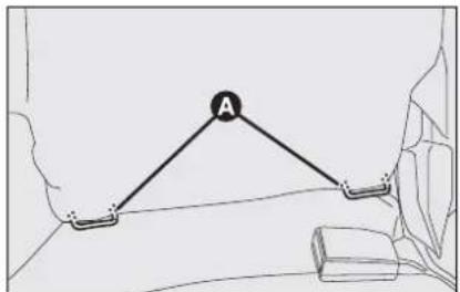
fig. 13

fig. 14
Lineaccessori Fiat provides the "Kiddy Isofix" seat, certified according to European Standard ECE-R44/03, for babies up to 13 kg weight to be positioned facing backwards (groups 0 and 0+) and for babies from 9 to 18 kg weight that is to be positioned facing the running direction (group 1). Remember that in case of Isofix type seats, you can only use those seats designed, tested and approved for this car.

WARNING
Mount the child restraint system only with the car stationary. The Isofix child restraint system is properly anchored to the mounting brackets when clicks are heard. In any case, keep to the installation instructions that must be provided by the child restraint system Manufacturer.

fig. 15

FOC0312m
FITTING THE ISOFIX TYPE SEAT
Groups 0 and 0+
For children of the 0, 0+ weight group (babies up to 13 kg), the child's seat is facing backwards and the child is restrained by the child's seat belts D-fig. 15.
As the child grows, passing to weight group I (9-18 kg) refit it facing forwards following the instructions provided with the child restraint system.
For proper mounting proceed as follows:
☐ move the rear sliding seat fully backwards with the seat back at 4^th position, as shown in fig. 16.
☐ check whether the release lever B-
fig. 15 is at rest position (inward);
☐ find the presetting brackets A, then position the child restraint system with the fastening devices C aligned with the brackets;
☐ push the child restraint system until hearing locking clicks;
□ check proper locking by moving the child's seat with force: the built-in safety mechanism actually inhibits improper coupling with only one coupling locked.

WARNING
In case of rear fixed seat and if the Isofix type restraint system is set facing backwards, the passenger's seat will have to be pulled back until it touches the seat restraint system back. In case of rear sliding seat, move the front seat forward to a position from half its stroke forth.
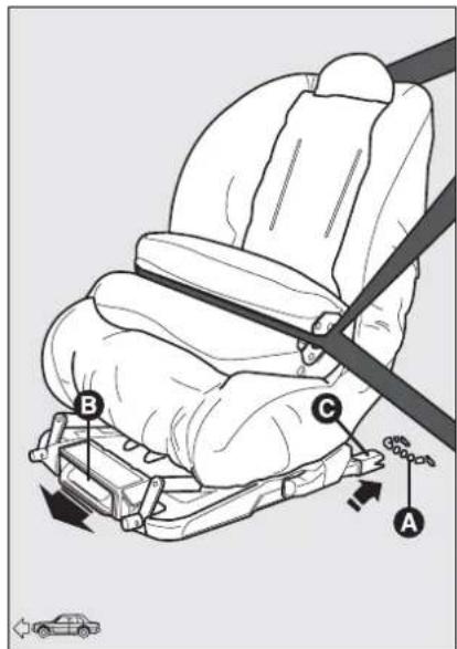
fig. 17

fig. 18
Group I
For proper mounting proceed as follows:
☐ move the rear sliding seat fully backwards with the seat back at 4^th position, as shown in fig. 16;
□ check whether the release lever B-
fig. 17 is at rest position (inward);
☐ find the presetting brackets A, then position the child restraint system with the fastening devices C aligned with the brackets;
☐ push the child restraint system until hearing locking clicks;
☐ for seats positioned facing the running direction, hook the upper belt D-fig. 18 (in the upper seat pocket) to the ring E in the boot;
☐ Check proper locking by moving the child's seat with force: the built-in safety mechanism actually inhibits improper coupling with only one coupling locked.
With this configuration, the child is secured also by the car seat belts and by the upper belts. To apply car seat belts to child's seat refer to the child's seat handbook.

WARNING
In case of rear sliding seat, move the front seat forward
to a position from half its stroke forth.
PRESETTING FOR MOUNTING THE "UNIVERSAL ISOFIX" CHILD RESTRAINT SYSTEM
This car is preset for mounting the "Universal Isofix" child restraint system, a new European standardised system for carrying children safely.
The "Universal Isofix" child's seat covers weight group: 1.
Due to its different anchoring system, the Universal Isofix child's seat shall be anchored to the proper lower metal rings A-fig. 19, set between rear seat back and cushion. The upper belt D-fig. 20 (provided with the child's seat) shall be then secured to ring E set in the boot at child's seat height.
It is possible to mount at the same time both the traditional restraint system and the "Universal Isofix" one.

fig. 19
FOC0274m
Remember that in case of Universal Isofix child's seat, you can only use all those seats approved with the marking ECE R44/03 "Universal Isofix".
At Lineaccessori Fiat is available the "Universal Isofix" "Duo Plus" child's seat.
For any further installation/use detail, refer to the "Instructions Manual" that must be provided by the child restraint system Manufacturer.

fig. 20
FOC0428m

WARNING
Mount the child restraint system only with the car sta-
tionary. The child restraint system is properly anchored to the mounting brackets when clicks are heard. In any case, keep to the installation instructions that must be provided by the child restraint system Manufacturer.
PASSENGER SEAT COMPLIANCE WITH REGULATIONS ON UNIVERSAL ISOFIX CHILD'S SEAT USE
The table below, according to ECE 16 European Directive, shows the different installation possibilities of Universal Isofix restraint systems on seats fitted with Isofix fasteners.
| Range of weight Child's seat orientation Isofix Isofix position | class side rear | ||
| Group 0 to 10 kg | Facing backwards | E | IL |
| Group 0+ to 13 kg | Facing backwards | E | IL |
| Facing backwards | D | IL | |
| Facing backwards | C | IL | |
| Group I - 9 to 18 kg | Facing backwards | D | IL |
| Facing backwards | C | IL | |
| Facing forwards | B | IUF | |
| Facing forwards | BI | IUF | |
| Facing forwards | A | IUF | |
Key
IUF = suitable for Isofix child restraint systems to be set facing forwards, universal class (fitted with third upper fastener), approved for the weight group.
IL = suitable for Isofix type child restraint systems, specific and approved for this type of car: Kiddy Isofix seat available at Lineaccessori Fiat. The child's seat can be installed by moving forward the front seat.
FRONT AIR BAGS
The car is fitted with front multistage air bags ("Smart bag") for driver and passenger, front side bags (where provided), rear side bags (where provided) and window bags (where provided).
"SMART BAG" SYSTEM (FRONT MULTISTAGE AIR BAGS)
The front air bag (driver and passenger) has been designed to protect the occupants in the event of head-on crashes of medium-high severity, by placing the cushion between the occupant and the steering wheel or dashboard.
Front air bags are designed to protect car's occupants in front crashes and therefore non-activation in other types of collisions (side collisions, rear shunts, rollovers, etc.) is not a system malfunction. In case of front crash, an electronic control unit, when required, triggers the inflation of the cushion according to the severity of the collision.
The cushion immediately inflates, placing itself as a protection between the body of the front occupants and the structure that could cause injuries. Immediately after, the cushion deflates.
The front air bag (driver and passenger) is not a replacement of but complementary to the use of belts, which should always be worn, as specified by law in Europe and most non-European countries.
In case of crash, a person not wearing the seat belt moves forward and may come into contact with the cushion while it is still inflating. Under this circumstance the protection offered by the air bag is reduced. Front air bag may not be activated in the following situations:
☐ in collisions against highly deformable objects not affecting the car front surface (e.g. bumper collision against guard rail);
□ car wedging under other vehicles or protective barriers (for example under a truck or guard rail);
as it offers no additional protection compared with the seat belts, consequently, it would be pointless. Therefore, failure to come into action in the above circumstances does not mean that the system is not working properly.

WARNING
Do not apply stickers or other objects to the steering
wheel or to the air bag cover on the passenger's side or on the side roof lining. Do not put objects on the dashboard on passenger side (e.g. mobile phones) since they could interfere with proper passenger air bag inflation and cause injuries to the car's passengers.
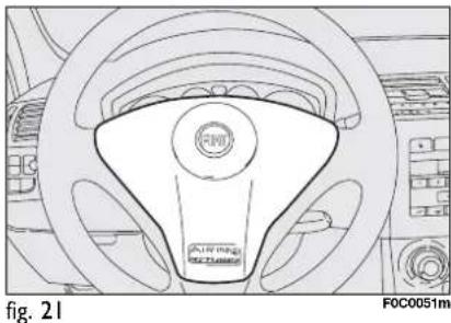
natural_image
Line drawing of a car steering wheel with FDC logo and brand mark (no text or symbols on the diagram itself)DRIVER'S FRONT AIR BAG fig. 21
It consists of an instant-inflating cushion contained in a special recess in the centre of the steering wheel.
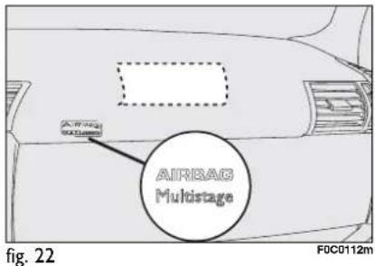
PASSENGER'S FRONT AIR BAG
fig. 22
It consists of an instant-inflating cushion contained into a special recess in the dashboard, this cushion has a volume bigger than that of the driver.
The driver's and passenger's front air bags have been designed and calibrated to improve the protection of a person wearing seat belts.
At their maximum inflation, their volume fills most of the space between the dashboard and the passenger.


WARNING
SERIOUS DANGER: With passenger's air bag active, never place child's seats with the cradle facing backwards since the air bag activation
could cause to the child serious injuries, even mortal. In the case of need, always deactivate the passenger's air bag when a child's seat is placed on the front seat. The front passenger's seat shall be adjusted in the most backward position to prevent any contact between child's seat and dashboard. Even if not compulsory by law, you are recommended to reactivate the air bag immediately as soon as child transport is no longer necessary.
MANUAL DEACTIVATION OF PASSENGER'S FRONT AIR BAG
Should it be absolutely necessary to carry a child on the front seat, the passenger's front air bag can be deactivated.
Deactivation/reactivation takes place with ignition key at STOP, and operating it in the special key switch on the right-hand side of the dashboard. You can reach the switch only if the door is opened.
When the door is open, the key can be inserted and removed in both positions.
IMPORTANT Operate the switch only when the engine is not running and the ignition key is removed.

fig. 23
The key-operated switch has two positions fig. 23:
□ Passenger's front air bag activated (ON position Ⓧ): warning light 📁 on instrument panel off; it is absolutely prohibited to carry a child on the front seat.
☐ Passenger's front air bag deactivated (OFF position 📋): warning light 📋 on instrument panel on; it is possible to carry a child protected by special restraint system on the front seat.
The warning light 🖼 on the instrument panel stays on permanently until the passenger's air bag is reactivated.
Deactivation of the passenger's front air bag does not inhibit operation of the side bag.
FRONT PASSENGER CLASSIFICATION SENSOR (OCS = Occupant Classification System) (where provided)
The front passenger air bag is equipped with a sensor, located inside the passenger seat between the padding and the external cover of the seat, able to recognize the presence of the occupant and classify his/her weight.
This allows ensuring the best protection under any circumstance, modulating the inflation pressure of the front passenger air bag as a function of the occupant weight.
If an adult sits on the front passenger seat, the relevant front air bag is ready to intervene in case of need. If the passenger seat is free, the air bag will not intervene.
IMPORTANT To receive the best system protection in the event of an accident, you have to seat in proper position.

WARNING
SERIOUS DANGER: The front passenger classification sensor is not studied for the recognition of the children restraints and for the consequent automatic deactivation of the passenger air bag. If you carry a children restraint on the front passenger seat, it is however necessary to deactivate the front passenger air bag through the proper deactivation switch (see previous paragraph).

WARNING
Do not arrange heavy objects on the front passenger seat, because in the event of accident, the front passenger air bag intervenes if it is not deactivated through the proper deactivation switch (see previous paragraph).

WARNING
The front passenger classification sensor could not detect or correctly classify the occupant presence because of the interposition of cushions or sanitary aids (cushions, rubber rings, etc.), that therefore should not be used on the front passenger seat.

WARNING
Never place cutting or sharp objects on the front passenger seat to prevent damaging the front passenger classification sensor. Contact a Fiat Dealership in case of sensor damages.
SIDE AIR BAGS (Side bag - Window bag)
SIDE BAG (where provided)
They are composed by two types of instant inflation cushions and are housed in the back rests of the front seats fig. 24 and in the side stuffing of the rear seats (where provided) fig. 25. The task of the side air bags is to increase protection of the occupants' chest in the event of a side crash of medium-high severity.
WINDOW BAG (where provided) fig. 26
They consist of two "curtain" cushions located behind the side coverings of the roof and covered by proper finishings; this solution, studied for the head protection, allows offering the best protection to the front and rear occupants in the event of side crash, thanks to the wide cushion inflation surface.
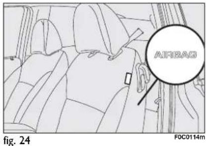

In minor side crashes (for which the restraining action of the seat belts is sufficient), the air bags are not deployed.

Also in this case it is of vital importance to wear the seat belts since in case of side crash they guarantee proper positioning of the occupant and prevent the occupants to be pitched out of the car in case of violent crashes.
Therefore the front and rear side bags (where provided) are not a replacement of but complementary to the belts, which you are recommended to always wear, as specified by law in Europe and most non-European countries.
IMPORTANT In the event of side crash, you can obtain the best protection by the system keeping a correct position on the seat, allowing thus a correct window bag unfolding.
IMPORTANT The front air bags and/or front and rear side bags (if fitted) may be deployed if the car is subject to heavy knocks or accidents involving the underbody area, such as for example violent shocks, against steps, kerbs or low obstacles, falling of the car in big holes or sags in the road.
IMPORTANT When the airbag inflates it emits a small amount of dusts. These dusts are harmless and is not the beginning of a fire; then the unfold cushion surface and the car interiors can be covered by a dusty remains: this dust can irritate skin and eyes. In case of contact, wash yourself using neutral soap and water.

WARNING
Life and validity of pyrotechnic charge and coil contact
are indicated on the label inside the lower oddment compartment. As this date approaches, contact Fiat Dealership to have them replaced.
IMPORTANT Should an accident occur in which any of the safety devices is activated, take the car to a Fiat Dealership to have the devices activated replaced and to have the system checked.
Every control, repair and replacement operations concerning the air bags must only be carried out c/o Fiat Dealership.
If you are having the car scrapped, have the air bag system deactivated at a Fiat Dealership first. If the car changes ownership, the new owner must be informed of the method of use of air bags and the above warnings and also be given this "Owner Handbook".
IMPORTANT The triggering of pretensioners, front air bags and side bags (front and rear) is decided in a differentiated manner by the electronic control unit, depending on the type of crash. The failure to deploy one or more of them does not mean that the system is not working properly

WARNING
Never rest head, arms and elbows on the door, on the windows and in the window bag area to prevent possible injuries during inflation phase.

WARNING
Never lean head, arms and elbows out of the window.
MANUAL DEACTIVATION OF REAR SIDE BAGS
(where provided)
Certain versions are fitted with rear side bags (that can be deactivated) to protect the chest of rear passengers.
For deactivation: operate the key switch (with ignition key) located in the boot under the rear shelves as shown in the figure. The switch can be reached only with tailgate open.
IMPORTANT Operate the switch only when the engine is stopped and the ignition key is removed.
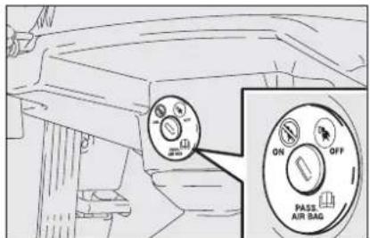
fig. 27
FOC0154m
The key-operated switch has two positions fig. 27:
□ side air bag activated (ON position Ⓧ): warning light 🎨 on instrument panel off; it is absolutely prohibited to carry a child on the rear seats;
□ side air bag deactivated (OFF position ^★ ): warning light ^★ on instrument panel on; it is possible to transport children protected by proper restraints on the front seat.

WARNING
SERIOUS DANGER: In presence of small size occupants (children, etc.) on the rear seats, it is necessary to deactivate the rear side bags

through the apposite deactivation switch located in the boot.
GENERAL WARNINGS

WARNING
If when turning the ignition key to MAR, the warning light does not turn on or if it stays on when travelling (together with the message on the display) there could be a failure in safety systems; in this event air bags or pretensioners could not trigger in case of impact or, in a minor number of cases, they could trigger accidentally. Contact Fiat Dealership immediately to have the system checked.

WARNING
Do not cover the backrest of front and rear seats with covers that are not suitable ed with side bags.

WARNING
Never travel with objects on your lap, in front of your chest or with a pipe, pencil, etc. between your lips; injury may result in the event of the air bag being triggered.

WARNING
Always keep your hands on the steering wheel rim when driving, so that if the air bag is triggered, it can inflate without meeting any obstacles which could cause serious harm to you. Do not drive with the body bent forwards, keep the seat back rest in the erect position and lean your back well against it.

WARNING
If the car has been stolen or an attempt to steal it has been made, if it has been subjected to vandals or floods, have the air bag system checked by Fiat Dealership.

WARNING
Remember that with the key engaged and at MAR, even with the engine not running, the air bags may be triggered on a stationary car if it is bumped by another moving car. Therefore, never seat children on the front seat even when the car is stationary. On the other hand, remember that with the key at STOP no safety system (air bags or pretensioners) is triggered in the event of an impact; in this case, failure to come into action cannot be considered as a sign that the system is not working properly.

WARNING
When the ignition key is turned to MAR, the warning light 🖼️ (with passenger's front air bag deactivation switch at ON) turns on and flashes for few seconds to remind that the passenger's air bag will be deployed in a crash, after which it should go off.

WARNING
When the ignition key is turned to MAR, the warning light (with the rear side bag deactivation switch at ON) turns on and flashes for few seconds to remind that the rear side bags will be deployed in a crash, after which it should go off.

WARNING
Do not wash the seat back rest with pressurised water or steam (by hand or at automatic seat washing stations).

WARNING
The front air bag is triggered for shocks greater in magnitude than the pretensioners. For impacts between these two thresholds, it is therefore normal that only the pretensioners are triggered.

WARNING
Do not hook rigid objects to the coat hooks and to the support handles.

WARNING
The air bag does not substitute the seat belts, but only increases their effectiveness. Moreover, since the front air bags do not come into operation in the event of front impact at low speed, side collisions, bumps from behind or overturning, in these circumstances the occupants would only be protected by the seat belts which must therefore always be fastened.
CORRECT USE OF THE CAR
ENGINE STARTING 136
PARKING....139
USING THE MANUAL GEARBOX 140
USING THE "SELESPEED" GEARBOX 141
CONTAINING RUNNING COSTS 149
TOWING TRAILERS.... 151
SNOW TYRES.... 154
SNOW CHAINS.... 155
CAR INACTIVITY 156
ENGINE STARTING
The car is fitted with an electronic engine lock device: if the engine fails to start, see the paragraph "The Fiat CODE system" in section "Dashboard and controls".
The engine may be noisier than usual during the first seconds of operation, especially after it has not been used for a while. This characteristic feature of the hydraulic tappet system does not compromise functionality or reliability. This timing system for petrol engines was adopted to limit servicing.
Engine starting is guaranteed up to a minimum temperature of -18^ (Italy and Middle Europe) and -20^ (North Europe).
STARTING PROCEDURE FOR PETROL VERSIONS
Proceed as follows:
□ pull up the handbrake;
□ set the gear lever to neutral;
☐ press the clutch pedal down to the floor without touching the accelerator;
□ turn the ignition key to AVV and let it go the moment the engine starts.
If the engine does not start at the first attempt, return the ignition key to STOP before repeating starting.
If, when the ignition key is at MAR, warning light remains lit together with warning light, turn the key to STOP and then back to MAR; if the warning light remains on, try with the other keys provided with the car.

We recommend that during the initial period you do not drive to full car performance (e.g.: excessive acceleration, long journeys at top speed, sharp braking, etc.).

WARNING
Running the engine in confined areas is extremely dangerous. The engine consumes oxygen and produces carbon monoxide which is a highly toxic and lethal gas.

When the engine is switched off never leave the ignition key at MAR to prevent pointless current absorption from draining the battery.
If you are still unable to start the engine, perform the emergency start-up procedure (see "Emergency start-up" in section "In an emergency") and contact Fiat Dealership.
IMPORTANT Never leave the ignition key at MAR when the engine is off.
STARTING PROCEDURE FOR DIESEL VERSIONS
Proceed as follows:
□ pull up the handbrake;
□ set the gear lever to neutral;
□ turn the ignition key to MAR. The warning lights 00 and 📋 on the instrument panel will turn on;
□ wait for the warning lights 📋 and 00 to turn off. The hotter the engine is, the quicker this will happen;
☐ press the clutch pedal down to the floor without touching the accelerator;
□ turn the ignition key to AVV as soon as warning light 00 turns off. If you wait too long you will lose the benefit of the work done by the glow plugs. Release the key as soon as the engine starts.
IMPORTANT With cold engine, the accelerator pedal shall be completely released while turning the ignition key to AVV.
If the engine does not start at the first attempt, return the ignition key to STOP before repeating starting.
If, when the ignition key is at MAR, warning light ☑ on the instrument panel stays on, turn the key to STOP and then back to MAR; if the warning light remains on, try with the other keys provided with the car.
If you still cannot start the engine, contact Fiat Dealership.
IMPORTANT Never leave the ignition key at MAR when the engine is off.

The warning light 00 will flash for 60 seconds at start-up or during prolonged cranking to signal a fault in the glow
plug heating system. You can use the car as usual if the engine starts but you should contact a Fiat Dealership as soon as possible.
HOW TO WARM UP THE ENGINE AFTER IT HAS JUST STARTED (petrol and diesel engines)
Proceed as follows:
Drive off slowly, letting the engine turn at medium revs. Do not accelerate abruptly;
☐Do not drive at full performance for the initial kilometres. Wait until the coolant temperature gauge starts moving.
EMERGENCY START-UP
If the instrument panel warning light stays on with fixed light, contact Fiat Dealership.
STOPPING THE ENGINE
Turn the ignition to STOP while the engine is idling.
IMPORTANT After a taxing drive, you should allow the engine to "catch its breath" before turning it off by letting it idle to allow the temperature in the engine compartment to fall.

Never bump start the engine by pushing, towing or coasting downhill as this could cause fuel to flow into the catalytic
exhaust system and damage it beyond repair.

WARNING
Remember that the servo-brake and power steering
are not operational until the engine has been started, therefore much effort than usual is required on the brake pedal and steering wheel.

A quick burst on the accelerator before turning off the engine serves absolutely no practical purpose, it wastes fuel
and is damaging especially to turbocharged engines.
PARKING THE CAR
Proceed as follows:
☐ Stop the engine and engage the hand-brake;
☐ Engage a gear (first if the car is faced up-hill or reverse if it is faced downhill) and leave the wheels steered.
Block the wheels with a wedge or a stone if the car is parked on a steep slope. Do not leave the ignition key at MAR to prevent draining the battery. Always remove the key when you leave the car.
HANDBRAKE
The handbrake lever is located between the two front seats.
Pull the handbrake lever upwards until the car cannot be moved.
Four or five clicks are generally enough when the car is on level ground while nine or ten may be required if the car is on a steep slope or laden.
IMPORTANT If this is not the case, contact Fiat Dealership to have the handbrake adjusted.
In cars fitted with front armrest, lift the latter so that it does not hinder the hand-brake engaging procedure.

WARNING
Never leave children unattended in the car. Always remove the ignition key when leaving the car and take it out with you.
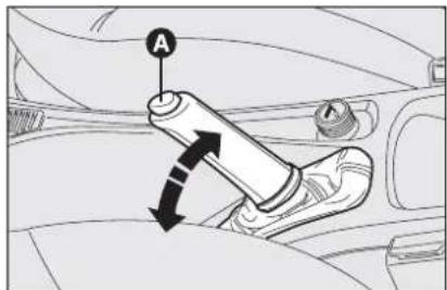
F0C0059m
When the handbrake lever is pulled up and the ignition key is at MAR, the instrument panel warning light (①) will turn on.
To release the handbrake:
☐ slightly lift the handbrake and press release button A-fig. I;
☐ keep button A pressed and lower the lever. Warning light (!) will turn off.
Press the brake pedal when carrying out this operation to prevent the car from moving accidentally.
USING THE MANUAL GEARBOX
To engage the gears, press the clutch pedal fully and shift the gear lever into one of the required positions (the diagram is shown on the knob fig. 2, fig. 3 and fig. 4).
To engage 6^th gear (version 1.416V and 1.9 Multijet16V) press the lever to the right to prevent engaging 4^th gear by mistake. A similar action is required to shift down from 6^th to 5^th .
IMPORTANT The car can only be put into reverse gear when it has stopped moving completely. With the engine running, before engaging the reverse, wait at least 2 seconds with the clutch pedal fully down to prevent damage and grating of the gears.
To engage reverse R from neutral, lift the sliding ring A-fig. 2 or B-fig. 3 under the knob and shift the lever to the right and back (1.416V, 2.416V, 1.616V and Multijet versions).
For versions 1.816V just shift lever C-fig. 4 to the right and back.
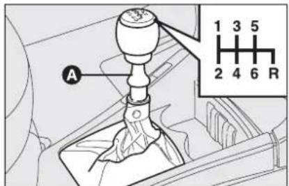
fig. 2
FOC0060m

WARNING
To change gears properly you must push the clutch pedal fully down. It is therefore essential that there is nothing under the pedals: make sure the mats are lying flat and do not get in the way of the pedals.

fig. 3
F0C0602m

fig. 4
F0C0310m

Do not drive with your hand resting on the gear lever as the force exerted, even if slight, could lead over time to pre-wear on the gearbox internalents.
USING THE "SELESPEED" GEARBOX (where provided)
The car may be fitted with a mechanical transmission with electronic control called "Selespeed". This device includes a conventional mechanical gearbox to which an electronically-operated electro-hydraulic device has been added which controls automatically the clutch and gear engagement.
The car moves off using only the accelerator pedal.
To be able to use the Selespeed correctly, this chapter should be read in full.
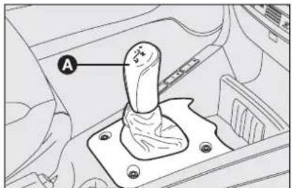
fig. 5
F0C0105m
OPERATION
The gearbox can work in two operating modes:
☐ the first mode is manual (MANUAL), the driver directly requests gearshifting;
☐ the second mode is automatic (AUTO), the system directly decides when shifting gear.
On versions fitted with Cruise Control, when activating it, the Selespeed gearbox will automatically set in AUTO mode. To select the manual mode deactivate the Cruise Control (see paragraph "Cruise Control" in section "Dashboard and controls").

fig. 6
FOC0111m
Manual mode (MANUAL)
In MANUAL mode, the display shows the gear engaged.
The requests to change gear may take place through:
□ the gear lever A-fig. 5 on the central console;
□ the steering wheel controls fig. 6, which can be operated only when the car speed exceeds 5 km/h.
It is not necessary to release the accelerator pedal when shifting gears.
Neutral (N) is accepted until the car speed exceeds 40 km/h. The reverse gear engagement (R) is accepted only if the car is stationary.

fig. 7
In the manual operating mode there are certain automatic/security devices which simplify driving:
Such operating mode is set when, with AUTO mode selected, the button AUTO fig. 7 is pressed again, thereby excluding the previously selected mode.
When downshifting, the engine is accelerated automatically to bring it to the speed necessary with the new gear ratio.
With the accelerator pedal pressed and gradual engine speed increase, gearshifting becomes quicker.
☐ when slowing down the clutch is opened and the transmission ratio is automatically reduced to be ready for picking up again; otherwise, when the car is stopped, the gearbox will automatically be in first gear (1);
☐ requests to change gear that would take the engine to exceed the maximum speed or below minimum speed are not accepted;
☐ nif the engine reaches the maximum permissible speed and accelerating continues (without the cutting in of the ASR or ESP system), the system automatically engages a higher gear; ASR or ESP system activation at max speed, gearshifting is inhibited;
☐ if jamming occurs during gear engagement, the system firstly tries to engage the gear required again and, if it is still not possible, it automatically engages the immediately higher one to avoid leaving the car in neutral (N).
IMPORTANT It is advisable to wait for the end of a gear shifting operation before requesting another one, to avoid multiple requests in rapid succession.
Automatic mode (AUTO)
This operating mode is selected by pressing button AUTO, on the central console.
In the AUTO operating mode, AUTO is displayed followed by the indication of the gear selected.
Releasing the accelerator pedal quickly, the system does not engage a higher gear in order to maintain an adequate level of engine brake.
The indication on the display of the gear selected, can be as follows:
N = neutral;
I = first gear;
2 = second gear;
3 = third gear;
4 = fourth gear;
5 = fifth gear;
R = reverse;
SYSTEM ACTIVATION
Turning the ignition key to MAR, after about one second, the display shows the gear engaged (N, 1, 2, 3, 4, 5, R): from this moment onwards, the Selespeed system accepts gearshift commands.
IMPORTANT If after 10 seconds the display does not show the gear engaged, turn the ignition key to STOP, and wait for the display to turn off, then repeat system switch on. If the fault persists, contact Fiat Dealership.
IMPORTANT When the driver's door is opened the system starts the hydraulic part of the system to prepare it for when the engine is started.
MOVING-OFF
With the engine on and the car stationary, the gears that can be engaged for moving off are only first (1), second (2) and/or reverse (R).
To engage them it is possible, keeping the brake pedal pressed, to use only the gearshift lever on the central console.
Moving off of the car is obtained releasing the brake pedal and gradually pressing the accelerator pedal.
With the ASR system off (pressing the ASR off button) moving off will be more "brilliant".
IMPORTANT Reverse gear (R) can be engaged from any of the following other gears: neutral (N), first (1) or second (2) only when the car is stationary.

WARNING
After a request to shift gear with the car stationary, before pressing the accelerator pedal to make the car move, the driver must always check the display to see that the gear engaged is the one required.
IMPORTANT If when shifting from reverse (R) / first (I) or neutral (N) / first (I) sticking occurs on the first gear, the system automatically engages second gear (2). This is not to be considered as a fault as it is part of the operating logic. For the same reason, in the case of sticking on reverse gear, the system partially closes the clutch to allow gear engagement; in this case the engagement of reverse gear (R) will not be as smooth as usual.
IMPORTANT NOTES
□ With the car stopped and a gear engaged always keep the brake pedal pressed until deciding to move off;
□ during prolonged halts with the engine running it is advisable to keep the gearbox in neutral;
☐ when the car is parked facing uphill, do not use the moving off manoeuvre to keep the car still; use the brake pedal and press the accelerator pedal only when the deciding to move off;
☐ use second gear (2) only when more control is needed for moving off manoeuvres at low speed;
☐ if, in reverse gear, first (1) gear is engaged or vice versa, shift gear only when the car is stopped completely and with the brake pedal pressed.

fig. 8
F0C00105m
Though highly inadvisable, if when travelling downhill for some unexpected reason the car is set to neutral (N), when the engagement of a gear is requested, the system automatically engages the best gear in relation to the speed of the car to allow the correct transmission of torque to the wheels.
When travelling downhill with a gear engaged and the accelerator released (if the car is moving), beyond a pre-established speed, the system engages the clutch automatically to give the car adequate engine braking.
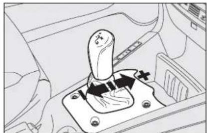
natural_image
Mechanical switch mechanism diagram showing lever and gear assembly (no text or labels)fig. 9
F0C0184m
GEARSHIFTING
Through lever
Gearshifting takes place through the control lever A-fig. 8, which is of the floating type with a "single central stable position". It is possible to request an increase/decrease of the gear ratio engaged and/or reverse gear engagement (R) or neutral (N).
To request gearshifting proceed as follows fig. 9:
□ shift upwards (+) push the lever forwards. If the system is in neutral (N) or in reverse (R) moving the lever forwards causes the engagement of first gear (I);
☐ to shift downwards (-) push the lever backwards.

natural_image
Mechanical switch mechanism diagram showing lever and gear assembly (no text or labels)fig. 10
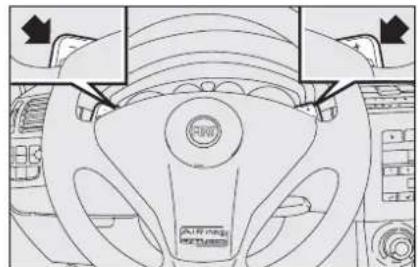
natural_image
Top-down view of a car steering wheel and dashboard (no text or symbols visible)fig. 11
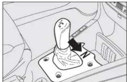
natural_image
Line drawing of a car gear shift lever inside a vehicle (no text or symbols)fig. 12
IMPORTANT Before using the gearshift control lever, always check the gear engaged on the display (N, 1, 2, 3, 4, 5, R).
With the engine off and the car stationary it is possible to engage all the gears.
With the car stopped and the brake pedal pressed, requests to change gear are accepted only through the control lever on the centre console.
From any gear (N, 1, 2, 3, 4, 5) and with the car practically stationary, it is possible to request the engagement of reverse gear pushing the lever to the right and then backwards fig. 10. If the car is moving, the request is not accepted. Wait for the car to stop and then request gear engagement again.
IMPORTANT Once a gear has been changed it is necessary to immediately release the gearshift control lever after making the request. A manoeuvre prolonged (over 10 seconds) will cause the system to switch automatically to AUTO; everything stops releasing the gearshift lever.
IMPORTANT When parking the car on a sloping road and engaging a gear to keep it braked, always check that the display shows the new gear engaged and wait for one or two seconds before releasing the brake pedal to allow complete engagement of the clutch.
Through steering wheel controls
They are placed on the steering wheel spokes fig. 11 through which, only with the car on the move (with speed above 5 Km/h), it is possible to shift gear up or down.
If during operation in the automatic mode (AUTO) a request to change gear is made, this is performed without switching the operating mode.
To allow setting to neutral (N), (with the car stationary and brake pedal pressed), move the gearshift lever to the right fig. 12.
ENGINE STARTING
The engine can be started either with a gear engaged or with the gearbox in neutral (N).
After starting, the gearbox sets to neutral automatically, the display shows the letter N and the system selects last operating mode (MANUAL or AUTO) before switching off.
IMPORTANT With gear engaged, fully depress the brake pedal to allow engine starting.
SWITCHING OFF THE ENGINE AND SYSTEM DEACTIVATION
Turning the ignition key to STOP the engine turns off.
The gear selected before switching off the engine remains engaged.
If the engine is stopped with the gearbox in neutral (N), letter N flashing on the display calls the driver's attention so that the car can be put in safety conditions engaging first gear (I) or reverse (R).
In this case, the ignition key should be turned to MAR and, with the brake pedal pressed, engage first gear (1) or reverse (R).

WARNING
If the engine fails to start with the gear engaged, the informed of the potentially us situation (due to the fact gearbox is in neutral) by the

WARNING
NEVER leave the car with the gear in neutral (N).
IMPORTANT If the engine is stopped with the AUTO mode engaged, this will be stored by the system. Indeed, the next time the engine is started, this condition will still be active.
IMPORTANT Should the engine go off with the car on the move, the next time it is started the warning light may come on. In this case check that the warning light goes off turning the engine off and on again with the car stationary. If not, contact Fiat Dealership.
FAILURE INDICATIONS
Failures of the Selespeed gearbox are shown by warning light ☐ on the instrument panel, together with the relevant message (see section "Warning lights and messages").
In case of system failure:
□ a buzzer will sound;
☐ where provided, the AUTO mode will be engaged automatically to make it possible to reach the nearest Fiat Dealership and have the fault eliminated.
In the case of a fault, the system only allows the engagement of first gear (1), second gear (2) and reverse (R).

WARNING
Never remove the ignition key when the car is moving. In addition to the fact that the Selespeed system would not work properly up to stopping the car, the steering wheel would lock automatically the first time it is turned.

WARNING
It is absolutely necessary to turn off the engine and then turn off the Selespeed system keeping the brake pedal pressed: ONLY release the pedal when the display on the instrument panel has gone out.

WARNING
In the event of a gearbox fault (to any component), contact Fiat Dealership as soon as possible to have the system checked over.
BUZZER WARNINGS
The buzzer is activated when:
□ reverse gear is engaged (R);
☐ clutch overheating occurs when moving off (in this case it is necessary to "force" start-up without hesitation or, if the car is on a slope, release the accelerator and use the brake pedal to stop the car);
☐ an attempt is made to start the engine with a gear engaged and the brake pedal is not pressed completely;
Still for safety reasons, when the car is stationary, with engine started gear engaged, the system activates the buzzer and automatically shifts to neutral (N) when:
☐ no action is made on the accelerator and/or brake pedal for at least 3 minutes;
☐ the brake is pressed for over 10 minutes;
□ the driver's door is opened and no action is made on the accelerator and brake by at least 2 seconds;
☐ a gearbox failure has been detected.
STOPPING THE CAR
To stop the car, simply release the accelerator pedal and, if necessary press the brake pedal.
Regardless of the gear engaged and the operating mode activated (MANUAL or AUTO) the system automatically disengages the clutch and shifts to a lower gear.
Stopping the car the system automatically engages the first gear (1).
PARKING THE CAR
To park the car safely it is absolutely necessary to engage first gear (I) or reverse (R) and also the handbrake if the car is on a slope.
When turning off the engine with the car on an uphill slope and a gear engaged, it is absolutely necessary to wait for the display showing the gear engaged to go off before releasing the brake pedal.
If the gearbox is in neutral (N) and wanting to engage a parking gear, the system should be activated and with the foot on the brake pedal it is necessary to engage first gear (I) or reverse (R).
TOWING THE CAR
See the instructions contained in paragraph "Towing the car" in section "In an emergency".
CONTAINING RUNNING COSTS
Here are some suggestions which may help you to keep the running costs of your car down and lower the amount of toxic emissions released into the atmosphere.
GENERAL CONSIDERATIONS
Car maintenance
Have checks and adjustments carried out in accordance with the "Service schedule".
Tyres
Check the pressure of the tyres routinely at an interval of no more than 4 weeks: if the pressure is too low, consumption levels increase as resistance to rolling is higher.
Unnecessary loads
Do not travel with too much luggage stowed in the boot. The weight of the car (especially when driving in town) and its trim greatly affects consumption and stability.
Roof rack/ski rack
Remove the roof rack or the ski rack from the roof as soon as they are no longer used. These accessories lower air penetration and adversely affect consumption levels. When needing to carry particularly voluminous objects, preferably use a trailer.
Electric devices
Use electric devices only for the amount of time needed. Rear heated window, additional headlights, windscreen wipers and heater fan need a considerable amount of energy, therefore increasing the requirement of current increases fuel consumption (up to +25% in the urban cycle).
Climate control
The air conditioner is an additional load which greatly affects the engine leading to higher consumption (on average up to +20%). When the temperature outside the car permits it, use the air vents where possible.
Spoilers
The use of non-certified aerodynamic items may adversely affect air drag and consumption levels.
DRIVING STYLE
Starting
Do not warm the engine with the car at a standstill or at idle or high speed: under these conditions the engine warms up much more slowly, increasing electrical consumption and emissions. It is therefore advisable to move off immediately, slowly, avoiding high speeds. This way the engine will warm faster.
Unnecessary actions
Avoid accelerating when waiting at traffic lights or before switching off the engine. This and also double declutching is absolutely pointless on modern cars and also increase consumption and pollution.
Gear selection
As soon as the conditions of the traffic and road allow, use a higher gear. Using a low gear to obtain brilliant performance increases consumption.
In the same way improper use of a high gear increases consumption, emissions an engine wear.
Top speed
Fuel consumption considerably increases with speed. Avoid superfluous braking and accelerating, which cost in terms of both fuel and emissions.
Acceleration
Accelerating violently increasing the revs will greatly affect consumption and emissions: acceleration should be gradual and should not exceed the maximum torque.
CONDITIONS OF USE
Cold starting
Short journeys and frequent cold starts do not allow the engine to reach optimum operating temperature. This results in a significant increase in consumption levels (from +15 to +30% on the urban cycle) and emission of harmful substances.
Traffic situations and road conditions
Rather high consumption levels are tied to situations with heavy traffic, for example in queues with frequent use of the lower gears or in cities with many traffic lights. Also winding mountain roads and rough road surfaces adversely affect consumption.
Traffic hold-ups
During prolonged hold-ups (traffic lights, level crossings) the engine should be switched off.
TOWING TRAILERS
IMPORTANT NOTES
For towing caravans or trailers the car must be fitted with a certified tow hook and an adequate electric system. Installation should be carried out by specialised personnel who release a special document for circulation on the road.
Install any specific and/or additional rear-view mirrors as specified by law.
Remember that when towing a trailer, steep hills are harder to climb, the braking spaces increase and overtaking takes longer depending on the overall weight.
Engage a low gear when driving downhill, rather than constantly using the brake.
The weight the trailer exerts on the car tow hook reduces by the same amount the actual car loading capacity. To make sure the maximum towable weight is not exceeded (given in the log book) account should be taken of the fully laden trailer, including accessories and personal belongings.
Do not exceed the speed limits of the country you are driving in. In any case do not exceed 100 km/h.
INSTALLING THE TOW HOOK
The towing device should be fastened to the body by specialised personnel according to any additional and/or integrative information supplied by the Manufacturer of the device.

WARNING
The ABS system with which the car may be fitted does not control the trailer braking system. Drive with extreme care on slippery roadbeds.

WARNING
Under no circumstances should the car brake system be altered to control the trailer brake. The trailer braking system must be fully independent of the car hydraulic system.
The towing device must meet current regulations with reference to 94/20/EC Directive and subsequent amendments.
For any version the towing device used must match the towable weight of the car on which it is to be installed.
IMPORTANT Supplementary electric loads other than external lights (e.g. electric brake, electric winch, etc.) shall be used with running engine.
Assembly diagram fig. 13-14
The tow hook structure must be fastened in the points shown by the symbol ⬆ using a total of 6 M10 screws.
Counterplates ① shall have a 4 mm min thickness.
Counterplates ② shall have a 6 mm min thickness.
The hook should be fastened to the body avoiding any type of drilling and trimming of the rear bumpers that remains visible when the hook is removed.
IMPORTANT It is compulsory to fasten a label (plainly visible) of suitable size and material with the following wording:
MAX LOAD ON BALL 60 kg
After fitting, screw holes shall be sealed to prevent exhaust gas inlet.

fig. 13 - Saloon versions

fig. 14 - Multi Wagon versions
SNOW TYRES
Use snow tyres of the same size as the normal tyres provided with the car.
Fiat Dealership will be glad to provide advice concerning the most suitable type of tyre for the customer's requirements.
For the type of tyre to be used, inflation pressures and the specifications of snow tyres, follow the instructions given in paragraph “Wheels” in section “Technical specifications”.
The winter features of these tyres are reduced considerably when the tread depth is below 4 mm. In this case, they should be replaced.
Due to the snow tyre features, under normal conditions of use or on long motorway journeys, the performance of these tyres is lower than that of normal tyres. It is therefore necessary to limit their use to the purposes for which they are certified.
IMPORTANT When snow tyres are used with a max speed index below the one that can be reached by the car (increased by 5%), place a notice in the passenger compartment, plainly in the driver's view which states the max permissible speed of the snow tyres (as per EC Directive).
All four tyres should be the same (brand and track) to ensure greater safety when driving and braking and better driveability.
Remember that it is inappropriate to change the direction of rotation of tyres.

WARNING
The max speed for snow tyres with "Q" marking is
160 km/h; 190 km/h for tyres with "T" marking and 210 km/h for tyres with H marking. The Road Traffic Code speed limits must however be always strictly observed.
SNOW CHAINS
Use of snow chains should be in compliance with local regulations.
Snow chains should only be applied to the driving wheels (front wheels).
Check the tension of the chains after the first few metres have been driven.
Use snow chains with reduced size: on tyres 195/65 R15" and 205/55 R16" use snow chains with reduced size with max protrusion beyond the tyre profile of 9 mm.
IMPORTANT Snow chains cannot be fitted to the space-saver spare wheel. So, if a front (drive) wheel is punctured and chains are needed, a rear wheel should be fitted to the front of the car and the spare wheel should be fitted to the rear.
This way with two normal drive wheels, snow chains can be fitted to them to solve an emergency.
IMPORTANT Snow chains may not be used on tyres type 215/45 R17 87W since interference can be generated with the surrounding components.


Keep your speed down when snow chains are fitted. Do
not exceed 50 Km/h. Avoid potholes, steps and pavements and avoid also to drive for long distances on roads not covered with snow to prevent damaging the car and the roadbed.
CAR INACTIVITY
If the car is to be left inactive for longer than a month, the following precautions should be noted:
☐ park the car in covered, dry and if possible well-ventilated premises;
□ engage a gear;
☐ check that the handbrake is not engaged;
☐ disconnect battery terminals (first disconnect the negative terminal) and check the battery charge. This check is to be repeated every three months when the car is left inactive. Recharge if the optical indicator shows a dark colour without the central green area;
□ clean and protect the painted parts using protective wax;
☐ clean and protect the shiny metal parts using special compounds readily available.
□ sprinkle talcum powder on the rubber windscreen and rear window wiper blades and lift them off the glass;
□ slightly open the windows;
☐ cover the car with a cloth or perforated plastic sheet. Do not use sheets of non-perforated plastic as they do not allow moisture on the car body to evaporate;
☐ inflate tyres to +0,5 bar above the normal specified pressure and check it at intervals;
□ if you don't disconnect the battery from the electric system, check its charge every month and recharge it if the optical indicator shows a dark colour without the central green area;
☐ do not drain the engine cooling system.
IMPORTANT Where relevant, switch off the electronic car alarm with the remote control.
WARNING LIGHTS AND MESSAGES
GENERAL WARNINGS 158
SIDELIGHTS AND LOW BEAMS 168
FOLLOW ME HOME 168
MAIN BEAMS.... 168
CRUISE CONTROL.... 168
POSSIBLE PRESENCE OF ICE ON THE ROAD...... 168
LIMITED RANGE 168
ASR SYSTEM 168
SPEED LIMIT EXCEEDED 168
WARNING LIGHTS AND MESSAGES
GENERAL WARNINGS
Turning on of warning light is accompanied by specific message and/or by buzzer sound where provided by instrument panel. These indications are concise and cautionary and shall not be considered as exhaustive and/or as an alternative to the specifications contained in this Owner Handbook which shall always be read through carefully and thoroughly. In case of failure indication always refer to the specifications contained in this section.
IMPORTANT Failure indications displayed are divided into two categories: very serious and less serious failures.
Very serious failures are indicated by a repeated and prolonged warning "cycle".
Less serious failures are indicated by a limited warning "cycle".
The warning cycle of both failure classes can be stopped by pressing button MODE. The instrument panel warning light will stay on until eliminating the fault.

Turning the ignition key to MAR the warning light turns on, but it should go off after few seconds.
Low brake fluid level
The warning light turns on when the level of the brake fluid in the reservoir falls below the minimum level, due to possible leak in the circuit.
The display will show the dedicated message.

WARNING
If the warning light Ⓑ turns on when travelling (together with the message on the display) stop the car immediately and contact Fiat Dealership.
Handbrake on
The warning light turns on when the hand-brake is on.
If the car is moving, a buzzer will also sound.
IMPORTANT If the warning light turns on when travelling, check that the handbrake is not engaged.

BRAKE PAD WEAR (red)
The warning light turns on when the front brake pads are worn; in this case have them changed as soon as possible.
The display will show the dedicated message.
IMPORTANT Since the car is fitted with wear sensors for the front brake pads, when changing them, check also the rear brake pads.

AIR BAG FAILURE (red)
Turning the ignition key to MAR the warning light turns on, but it should go off after few seconds.
The warning light stays on permanently if there is a failure in the air bag system. The display will show the dedicated message.

WARNING
The failure of the warning light ⚡️ (warning light off) is also indicated by the flashing for more than the normal 4 seconds of the passenger's front air bag deactivated warning light 📁.

FRONT PASSENGER'S AIR BAG
DEACTIVATED
(amber)
Warning light will come on when deactivating the passenger front air bag. With passenger front air bag active, turning the ignition key to MAR, warning light will turn on with fixed light for about 4 seconds and then it will flash for other 4 seconds. It shall then go off.

WARNING
If when turning the ignition key to MAR, the warning
light does not turn on or if it stays on when travelling (together with the message on the display) there could be a failure in safety systems; in this event air bags or pretensioners could not trigger in case of impact or, in a minor number of cases, they could trigger accidentally. Contact Fiat Dealership immediately to have the system checked.

WARNING
Warning light 📁 indicates also warning light 🌐 failures.
This is indicated by intermittent flashing, over 4 seconds, of warning light. In this event warning light indicates that there could be a failure in safety systems. Contact Fiat Dealership immediately to have the system checked.

REAR SIDE BAGS DEACTIVATED (where provided) (amber)
Warning light 🎨 turns on when rear side bags are deactivated.
With rear side bags on, turning the ignition key to MAR, warning light will turn on with fixed light for about 4 seconds and then it will flash for other 4 seconds. It shall then go off.

SEAT BELTS NOT FASTENED (red)
The warning light turns on glowing steadily with car stationary and driver's seat belt not fastened correctly. The warning light will turn on flashing together with the buzzer when, with car moving, the driver's seat belt is not fastened correctly.
The S.B.R. (Seat Belt Reminder) buzzer can only be excluded by Fiat Dealership.
The system can be reactivated through the set-up menu.

LOW BATTERY CHARGE (red)
Turning the ignition key to MAR the warning light turns on, but it should go out as soon as the engine is started (with the engine running at idle speed a brief delay in going out is allowed).
If the warning light stays on glowing steadily or flashing, contact immediately Fiat Dealership.

LOW ENGINE OIL PRESSURE (red)
EXHAUST OIL (red) (Multijet versions with DPF)
Low engine oil pressure
Turning the ignition key to MAR the warning light turns on, but it should go out as soon as the engine is started.
The display will show the dedicated message.

If the warning light turns on when the car is travelling (together with the message on the display), stop the engine
immediately and contact a Fiat Deal- ership.
Exhaust oil
(Multijet versions with DPF)
The warning light with turn on flashing when the system detects that the engine oil is exhaust.
After the first indication, at each engine starting the warning light 📋 will go on flashing for about 1 minute and then every 2 hours until oil is changed.
The display will show the dedicated message.

If warning light flashes, contact Fiat Dealership as soon as possible to have oil changed and instrument pan-
el warning light turned off.

SELESPEED TRANSMISSION FAILURE (red)
Turning the ignition key to MAR the warning light turns on, but it should go out as soon as the engine is started.
The warning light with turn on flashing (together with the message on the display) when there is a failure in the Selespeed transmission.

WARNING
In the event of Selespeed transmission failure, go as soon as possible to the nearest Fiat Dealership and have the system checked.

"DUALDRIVE" ELECTRIC POWER STEERING FAILURE (red)
Turning the ignition key to MAR the warning light turns on, but it should go off after few seconds.
If the warning light stays on, you will not have steering assistance and the effort on the steering wheel will be increased, steering is however possible. Contact Fiat Dealership.
The display will show the dedicated message.

HIGH TEMPERATURE ENGINE COOLANT FLUID (red)
Turning the ignition key to MAR the warning light turns on, but it should go off after few seconds.
The warning light turns on when the engine is overheated.
If the warning light comes on when driving, proceed as follows:
☐ normal driving conditions: stop the car, switch off the engine and check whether the water level in the reservoir is not below the MIN mark. Otherwise wait for few seconds to allow engine cooling, then open slowly and carefully the cap, top up coolant and check whether its level is falling between MIN and MAX marks in the reservoir. Check visually any leak and if when restarting the warning light comes on again, contact a Fiat Dealership.
☐ Car heavy duty (e.g.: towing trailer uphill of fully laden car): decrease speed, if the warning light stays on, stop the car. Wait for 2 or 3 minutes leaving the engine on and slightly accelerated to further activate the circulation of the coolant fluid, then switch the engine off. Check proper coolant level as described previously.
IMPORTANT Under severe use of the car, keep the engine on and slightly accelerated for few minutes before switching it off.
The display will show the dedicated message.

INCOMPLETE DOOR LOCKING (red)
The warning light turns on when one or more doors, the boot or the bonnet are not properly shut.
The display will show the dedicated message.
The buzzer will sound when one or more doors are open and the car is moving.

GENERIC FAILURE INDICATION (amber)
The warning light turns on in the following circumstances.
Inertial fuel cut-off switch intervened
The warning light turns on when the inertial fuel cut-off switch is triggered. The display will show the dedicated message.
Sensor failure
The warning light turns on when a fault is detected to one of the following sensors (where provided):
□ window anti-pinch sensors;
□ engine oil pressure sensor;
□ twilight sensor;
□ rain sensor;
□ parking sensors;
The display will show the dedicated message (excluding in the event of engine oil pressure sensor failure).
Contact Fiat Dealership as soon as possible to have the fault removed.
DIESEL PARTICULATE FILTER CLOGGED (amber) (Multijet versions)
The warning light turns on when the diesel particulate filter is clogged and the driving conditions do not enable to activate automatically the reclaiming procedure.
To enable the cleaning procedure, keep the car running until the warning light turns off.
The display will show the dedicated message.

Turning the ignition key to MAR the warning light turns on, but it should go off after few seconds.
The warning light turns on when about 8 litres fuel are left in the tank. The display will show the dedicated message.
IMPORTANT The warning light flashes to indicate a failure, contact Fiat Dealership as soon as possible to have the system checked.

ENGINE CONTROL SYSTEM FAILURE (EOBD) (amber)
In normal conditions, turning the ignition key to MAR, the warning light turns on, but it should go off when the engine has started. The initial turning on indicates that the warning light is working properly. If the warning light stays on or turns on when travelling:
☐ glowing steadily: means a fault in the supply/ignition system which could cause high emissions at the exhaust, possible lack of performance, poor handling and high consumption levels.
The display will show the dedicated message.
In these conditions it is possible to continue driving without however requiring heavy effort or high speed from the engine. Prolonged use of the car with the warning light on may cause damages. Contact Fiat Dealership as soon as possible.
The warning light turns off if the fault disappears, but it is still stored by the system.
☐ flashing: indicates the possibility of damage to the catalyst (see "EOBD system" in section "Dashboard and controls").
If the light flashes, it is necessary to release the accelerator pedal to lower the speed of the engine until the warning light stops flashing; continue the journey at moderate speed, trying to avoid driving conditions that may cause further flashing and contact Fiat Dealership as soon as possible.

If, turning the ignition key to MAR, the warning light does not turn on or if it turns on glowing steadily or flashing
when travelling, contact Fiat Dealership. Warning light operation can be checked by traffic agents by proper equipments, therefore comply with laws and regulations of the country where you are driving.

ESP SYSTEM (amber)
) Turning the ignition key to MAR the warning light turns on, but it should go off after few
seconds.
If the warning light does not turn off or stays on when travelling together with the button led ASR, contact Fiat Dealership.
The display will show the dedicated message.
Disconnecting the battery will make the warning light turn on (together with the message on the display) to indicate that the system shall be realigned. To make the warning light turn off carry out the initialisation procedure described at paragraph "ESP system" in section "Dashboard and controls".
Warning light flashing when driving indicates that the ESP system is active.

GLOW PLUG WARMING FAILURE (Multijet versions) (amber)
GLOW PLUGS (Multijet versions) (amber)
Glow plug warming
Turning the ignition key to MAR the warning light turns on and it will go off when glow plugs reach the preset temperature. Start the engine immediately after warning light turning off.
IMPORTANT With hot ambient temperature, warning light stays on for very short time.
Glow plug warming failure
The warning light flashes when there is a failure in the glow plug warming system. Contact Fiat Dealership as soon as possible.
The display will show the dedicated message.

WATER IN DIESEL FUEL FILTER
(Multijet versions) (amber)
Turning the ignition key to MAR the warning light turns on, but it should go off after few seconds.
The warning light turns on when there is water in the diesel fuel filter.
The display will show the dedicated message.

The presence of water in the fuel circuit may cause serious damage to the entire injection system and cause irregular engine operation. If the warning light turns on (together with the message on the display), contact Fiat Dealership as soon as possible to have the system relieved. If the above indications come on immediately after refuelling, water has probably been poured into the tank: turn the engine off immediately and contact Fiat Dealership.
INEFFICIENT ABS SYSTEM (amber)
Turning the ignition key to MAR the warning light turns on, but it should go off after few seconds.
The warning light turns on when the system is inefficient or unavailable. In this case the braking system keeps its effectiveness unchanged, but without the potential offered by the ABS system.
Caution is advisable and it is necessary to contact Fiat Dealership.
The display will show the dedicated message.


INEFFICIENT EBD (ELECTRONIC BRAKING
DISTRIBUTOR) (red) (amber)
The turning on at the same time of warning lights Ⓐ and ⚫ with the engine running indicates an EBD system failure or that the system is unavailable; in this case heavy braking may cause the rear wheels to lock before time, with the possibility of skidding.
Drive with the utmost care to the nearest Fiat Dealership to have the system checked.
The display will show the dedicated message.

CAR PROTECTION SYSTEM FAILURE-FIAT CODE (amber)
ALARM FAILURE (where provided) (amber) BREAK-IN ATTEMPT (amber)
Car protection system failure
Turning the key to MAR the warning light shall flash only once and then go off.
The turning on of the warning light glowing steadily, with the ignition key at MAR, indicates a probable failure (see “Fiat Code system” in section “Dashboard and controls”).
IMPORTANT The turning on at the same time of the 📋 and ⚪ warning lights indicates a failure of the Fiat CODE system.
If with the engine running the warning light flashes (together with the message on the display), this means that the car is not protected by the engine immobilising device (see "Fiat Code system" in section "Dashboard and controls"). Contact Fiat Dealership to have all the keys memorised.
Alarm failure (where provided)
The turning on of the warning light indicates a failure in the alarm system. Contact Fiat Dealership as soon as possible.
The display will show the dedicated message.
Break-in attempt
The turning on of the warning light indicates an attempt of break-in. Contact Fiat Dealership as soon as possible.
The display will show the dedicated message.

EXTERNAL LIGHT FAILURE (amber)
The warning light turns on when one of the following lights
is failing:
□ side/taillights
□ brake lights or relevant fuse
□ rear fog lights
□ direction indicators
□ number plate lights.
The failure referring to these lights could be: one or more blown bulbs, a blown protection fuse or an electric connection cut-off.
The display will show the dedicated message.

REAR FOG LIGHTS (amber)
The warning light turns on when the rear fog lights are turned on.

FRONT FOG LIGHTS (green)
The warning light turns on when the front fog lights are turned on.

LEFT-HAND DIRECTION INDICATOR (green - intermittent)
The warning light turns on when the direction indicator stalk is moved downwards or, together with the right indicator, when the hazard warning light button is pressed.

RIGHT-HAND DIRECTION INDICATOR (green - intermittent)
The warning light turns on when the direction indicator stalk is moved upwards or, together with the left indicator, when the hazard warning light button is pressed.

SIDELIGHTS AND LOW BEAMS (green) FOLLOW ME HOME
Side/taillights and low beams
The warning light turns on when side/tail-lights, parking lights or low beams are turned on.
Follow me home
The warning light turns on when activating the "Follow me home" device (see section "Dashboard and controls"). The display will show the dedicated message.

MAIN BEAMS (blue)
The warning light turns on when the main beams are turned on.

CRUISE CONTROL (where provided) (green)
Turning the ignition key to MAR the warning light turns on, but it should go off after few seconds.
The warning light turns on when turning the Cruise Control knurled ring to ON.
The display will show the dedicated message.
POSSIBLE PRESENCE OF ICE ON THE ROAD
The outside temperature indication starts flashing and symbol ✦ appears on the display when the outside temperature reaches or falls below 3°C to warn the driver of the possible presence of ice on the road.
The display will show the dedicated message.
LIMITED RANGE
The display will show the dedicated message to warn the driver that the cruising range is less than 50 km.
ASR SYSTEM
The ASR system can be turned off by pressing the ASR button. The display will show the dedicated message to warn the driver that the system is off; at the same time the button led will turn on.
Pressing again the ASR button will turn off the button led and the display will show the dedicated message to warn the driver that the system is active again.
SPEED LIMIT EXCEEDED
The warning light turns on when the car exceeds the speed limit set previously (see "Multifunction Display" in section "Dashboard and controls"). The display will show the dedicated message.
IN AN EMERGENCY
ENGINE STARTING.... 170
IF A TYRE IS PUNCTURED 171
QUICK TYRE REPAIR KIT FIX & GO automatic ..... 177
WHEN NEEDING TO CHANGE A BULB .... 181
IF AN EXTERIOR LIGHT BURNS OUT .... 184
IF AN INTERIOR LIGHT BURNS OUT.... 192
IF A FUSE BLOWS 196
IF THE BATTERY IS FLAT 205
JACKING THE CAR 206
TOWING THE CAR 206
FIRE EXTINGUISHER 208
ENGINE STARTING
JUMP STARTING
If the battery is flat, it is possible to start the engine using an auxiliary battery with the same capacity or a little higher than the flat one.
Proceed as follows fig. 1:
☐ Connect positive terminals (+ near the terminal) of the two batteries with a jump lead;
☐ With a second lead, connect the negative terminal (−) of the auxiliary battery and to an earthing point ↓ on the engine or the gearbox of the car to be started;
□ Start the engine;
☐ When the engine has been started, remove the leads reversing the order above.
If after a few attempts the engine does not start, do not insist but contact the nearest Fiat Dealership.
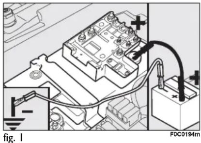
IMPORTANT Do not directly connect the negative terminals of the two batteries: sparks could ignite the flammable gas from the battery. If the other battery is fitted in another car, prevent accidental contacts between the metal parts of the two cars.

Under no circumstances should a battery charger be used to start the engine: it could damage the electronic
systems and in particular the ignition and injection control units.

WARNING
Do not carry out this procedure if you lack experience;
if it is not done correctly it can cause very intense electrical discharges. In addition, the fluid contained in the battery is poisonous and corrosive. Avoid contact with skin and eyes. You are also advised not to put naked flames or lighted cigarettes near the battery and not to cause sparks.
BUMP STARTING
Never bump start the engine (by pushing, towing, or coasting downhill) as this could cause fuel to flow into the catalytic exhaust system and damage it beyond repair.
IMPORTANT Remember that the servo-brake and electrical power steering system are not operating until the engine is started, a greater effort will therefore be required to press the brake pedal or turn the steering wheel.
IF A TYRE IS PUNCTURED
GENERAL INSTRUCTIONS
Wheel changing and correct use of the jack and space-saver spare wheel call for some precautions as listed below.
IMPORTANT If the car is fitted with "Fix & Go (quick tyre repair kit)", see the relevant instructions in the following chapter.

WARNING
Alert other drivers that the car is stationary in compliance with local regulations: hazard warning lights, warning triangle, etc. Any passengers on board should leave the car, especially if it is heavily laden. Passengers should stay away from on-coming traffic while the wheel is being changed. If parked on a slope or rough surface, chock the wheels with wedges or other suitable devices to prevent the car from rolling.

WARNING
The space-saver spare wheel (where provided) is specific to your car, do not use it on other models, or use the spare wheel of other models on your car. The space-saver spare wheel shall only be used in an emergency. It shall only be used for the distance necessary to reach a service point and the car speed shall not exceed 80 Km/h. The spare wheel has an orange sticker that summarises the main cautions for use and limitations. The sticker should never be removed or covered. Never fit a wheel cap on a space-saver spare wheel. The sticker gives the following information in four languages: caution! For temporary use only! 80 km/h max! Replace by normal wheel as soon as possible. Do not cover this label.

WARNING
When driving with a space-saver spare wheel fitted, the driving performance of the car changes. Avoid accelerating or braking sharply, abrupt turns or fast cornerings. The life of the spare wheel is approx. 3000 Km, after this distance it should be replaced with another of the same type. Never attempt to fit a conventional tyre on a rim designed for use as a space-saver spare wheel. Have the punctured wheel repaired and refitted as soon as possible. Two or more space-saver spare wheels should never be used together. Do not grease the threads of bolts before installing them: they might slip out.

WARNING
The jack shall only be used for changing wheels on the car with which it is provided or on cars of the same model. It must not be used for other purposes such as for instance raising cars of other models. In no case should it be used for repairs under the car. Incorrect positioning of the jack may cause the jacked car to fall. Do not use the jack for higher capacities than stated on its label. Snow chains cannot be fitted to the space-saver spare wheel. So, if a front (drive) wheel is punctured and chains are needed, a rear wheel should be fitted to the front of the car and the spare wheel should be fitted to the rear. This way with two normal drive wheels, snow chains can be fitted to them to solve an emergency.

WARNING
Fasten the wheel cap correctly to prevent the wheel from coming free in motion. Never tamper with the inflation valve. Never place tools between the rim and tyre. Check and restore, if required, the pressure of tyres and spare wheel to the values given in section "Technical specifications".
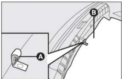
fig. 2
Please note:
☐ the jack weight is 1,76 kg; the jack requires no adjustment; the jack cannot be repaired: if it breaks it must be replaced with a new genuine jack; no tool other than its cranking device may be fitted on the jack.
To change a wheel proceed as follows:
☐ Stop the car is a position that is not dangerous for oncoming traffic where you can change the wheel safely. The ground should be flat and adequately firm; turn the engine off and pull up the handbrake; engage first gear or reverse; use the handle A-fig. 2 to remove the piece of stiff cover B (saloon versions) or C-fig. 3 (Multi Wagon versions); loosen the clamping device E-fig. 4;
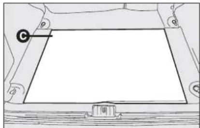
natural_image
Technical line drawing of a mechanical component with no visible text or symbolsfig. 3
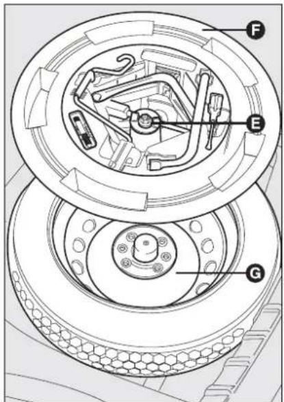
fig. 4

natural_image
Technical line drawing of a car wheel assembly with two circular components (no text or symbols)fig. 5
F0C03963m
☐ take out the tool container F-fig. 4 and take it near to the wheel to be changed; take out the space-saver spare wheel G; remove the wheel cap H-fig. 5 (versions with steel rims), or remove the wheel hub cap (versions with alloy rims);

☐ using the wrench provided L-fig. 6 loosen the fastening bolts by about one turn; if the car is fitted with alloy rims, shake the car to facilitate removing this rim from the wheel hub;
☐ work the jack crank M-fig. 7 to extend it until the groove N on the upper part of the jack is correctly inserted on the lower profile P of the body in point Q (at approx. 72 cm from the front wheel centre or 75 cm from rear wheel centre);
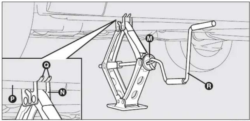
fig. 7
□ warn anybody nearby that the car is about to be lifted. They must stay clear and not touch the car until it is back on the ground;
☐ fit the handle R-fig. 7 to operate the jack and raise the car until the wheel is a few centimetres from the ground;
□ undo the wheel bolts and remove the wheel.
☐ make sure the contact surfaces between spare wheel and hub are clean so that the fastening bolts will not come loose;

fig. 8
F0C0396m
☐ install the space-saver spare wheel matching the holes S-fig. 8 with the corresponding pins T;
☐ using the wrench provided, fully tighten the four fastening bolts;
☐ work the jack handle R-fig.7 to lower the car and remove the jack;
☐ using the wrench provided, tighten up the wheel bolts in a criss-cross fashion following the sequence shown in fig. 9.
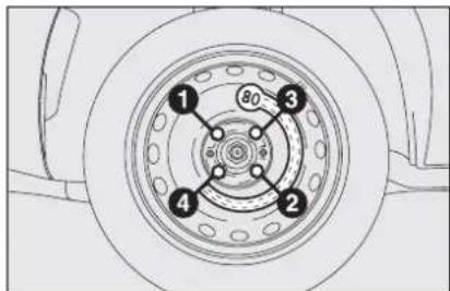
fig. 9
F0C0397m
REFITTING THE STANDARD WHEEL
Following the procedure described previously, raise the car and remove the spare wheel.
Versions with steel rims
Proceed as follows:
☐ Make sure the contact surfaces between standard wheel and hub are clean so that the fastening bolts will not come loose;
☐ Fit the normal wheel matching the holes S-fig. 8 with the corresponding pins T;
□ Using the wrench provided, tighten the fastening bolts;
☐ Lower the car and remove the jack;
☐ Using the wrench provided, fully tighten the bolts in the sequence shown in fig. 9;
☐ Place the cap near the wheel so that the inflation valve can come through the slot provided on the cap;
☐ Press the circumference of the cap, starting from the parts nearest the inflation valve until it is inserted completely.
IMPORTANT Incorrect fitting may cause the wheel cap to come off when the car is travelling.

Versions with alloy rims
Proceed as follows:
☐ Tighten the pin A-fig. 10 in one of the fastening bolt holes on the wheel hub;
☐ Insert the wheel on the pin and, using the wrench provided, tighten the four bolts available. This is facilitated by the extension provided B;
☐ Loosen the pin A and tighten the last fastening bolt;
☐ Lower the car and remove the jack;
☐ Using the wrench provided, fully tighten the bolts in the sequence shown previously for the space-saver spare wheel (see fig. 9).
When you have finished
□ Stow the space-saver spare wheel G-fig. 11 in the space provided in the boot;
☐ Insert the partially open jack into the container F and force it slightly into its seat so that it does not vibrate when the car is moving;
☐ Put the tools back into their places in the container;
☐ Stow the container complete with tools on the spare wheel and secure everything with the clamping device E;
☐ Correctly reposition the boot stiff cover.
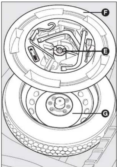
fig. 11
QUICK TYRE REPAIR KIT FIX & GO automatic
The quick tyre repair kit Fix & Go automatic is located in the appropriate container in the boot.
The quick tyre repair kit includes fig. 12:
☐ bottle A containing sealer and fitted with:
- filler hose B
- sticker C with caution "max. 80 km/h", to be affixed in a visible position for the driver (instrument panel) after repairing the tyre
☐ instruction brochure (see fig. 13), to be used for prompt and proper use of the quick repair kit and to be then handed to the personnel charged with handling the treated tyre
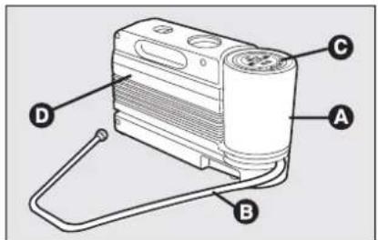
fig. 12
F0C0510m
□ compressor D including gauge and connections
☐ a pair of protection gloves located in the side space of the compressor
□ adapters for inflating different elements.

WARNING
Hand the instruction brochure to the personnel
charged with treating the tyre re-paired with the kit.

fig. 13
FOC0511m

In the event of a puncture caused by foreign bodies, it is possible to repair tyres showing damages on the track or up to max 4 mm diameter.

WARNING
Holes and damages on the tyre side walls cannot be repaired. Do not use the quick tyre repair kit if damaging is due to running with flat tyre.

WARNING
Repairs are not possible in case of damages on the wheel rim (bad groove distortion causing air loss). Do not remove foreign bodies (screws or nails) from the tyre.
IT SHOULD BE NOTICED THAT:
The sealing fluid of the quick tyre repair kit is effective with external temperatures between -20^ and +50^ .

WARNING
The compressor shall not be operated for more than 20 minutes. Risk of overheating!. Tyres repaired with the quick tyre repair kit shall be used temporarily only.

Do not throw away the cylinder and the sealing fluid. Have the sealing fluid and the cylinder disposed of in compliance with national and local regulations.

WARNING
The cylinder contains ethylene glycol. The cylinder contains latex: it can cause allergic reactions. It is harmful if ingested or inhaled and irritant for the eyes and in case of contact. In case of contact rinse immediately with water and take off contaminated clothes. If swallowed, do not induce vomit, rinse out the mouth, drink a lot of water and call the doctor immediately. Keep away from children. This product must not be used by asthmatics. Do not inhale vapours. Call the doctor immediately in case of allergic reactions. Keep the cylinder in the space provided for the purpose and far from heat. The sealing fluid has limited life. Replace the cylinder if sealer has run out.

fig. 14
F0C0513m
INFLATING PROCEDURE

WARNING
Put on the protection gloves provided together with quick tyre repair kit.
☐ Pull up the handbrake. Loosen tyre inflation valve cap, take out the filler hose A-fig. 14 and screw the ring nut B on the tyre valve;

☐ make sure the compressor switch E-fig. 16 is set to 0 (off), start the engine and fit plug D-fig. 15 into the cigar lighter outlet and then turn on the compressor by setting switch E-fig. 16 to I (on). Inflate the tyre to the pressure specified in paragraph "Cold tyre inflation pressure" in section "Technical Specifications". Check tyre pressure on gauge F-fig. 16 with compressor off to obtain precise reading;
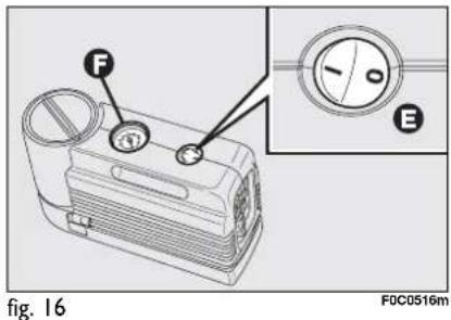
☐ If after 5 minutes it is still impossible to reach at least 1.5 bar, disengage compressor from valve and current outlet, then move the car forth for approx. ten metres in order to distribute the sealing fluid inside the tyre evenly, then repeat the inflation operation;
☐ If after this operation it is still impossible after 5 minutes to reach at least 1.8 bar, do not start driving since the tyre is excessively damaged and the quick tyre repair kit cannot guarantee suitable sealing, contact Fiat Dealership;
☐ If reaching the tyre pressure specified in paragraph "Cold tyre inflation pressure" in section "Technical Specifications", start driving immediately;

WARNING
Apply the sticker in a visible position for the driver to indicate that the tyre has been treated with the quick tyre repair kit. Drive carefully especially when cornering. Do not exceed 80 km/h. Avoid heavy braking and accelerating.
□ after driving for about 10 minutes stop and check again the tyre pressure; pull up the handbrake;

WARNING
If the pressure falls below 1.8 bars, do not drive any further: the quick tyre repair kit Fix & Go automatic cannot guarantee proper hold because the tyre is too much damaged. Contact Fiat Dealership.
☐ if at least 1.8 bar pressure is read, restore proper pressure (with engine running and handbrake on) and restart;
□ drive with the utmost care to the nearest Fiat Dealership.

WARNING
It is of vital importance to communicate that the tyre
has been repaired using the quick tyre repair kit. Hand the instruction brochure to the personnel charged with treating the tyre repaired with the kit.

natural_image
Line drawing of a car wheel connected to a battery pack (no text or symbols)fig. 17
FOC0S17m
FOR CHECKING AND RESTORING PRESSURE ONLY
The compressor can be also used just for restoring pressure. Disconnect the quick connection and connect it directly to the tyre valve fig. 17; in this way the cylinder is not connected to compressor and the sealing fluid will not flow into the tyre.

fig. 18
FOC0512m
CYLINDER REPLACEMENT PROCEDURE
To replace the cylinder proceed as follows:
□ disconnect connection B-fig. 18;
□ turn counter-clockwise the cylinder to replace and raise it;
☐ fit the new cylinder and turn it clockwise;
□ connect connection B to the cylinder and fit the transparent tube A into the proper space.
WHEN NEEDING TO CHANGE A BULB
GENERAL INSTRUCTIONS
☐ When a light is not working, check that the corresponding fuse is intact before changing a bulb. For the location of fuses, refer to the paragraph “If a fuse blows” in this section;
☐ Before changing a bulb check the contacts for oxidation;
☐ Burnt bulbs must be replaced by others of the same type and power;
□ Always check the height of the head-light beam after changing a bulb.

Halogen bulbs must be handled touching only the metallic part. If the transparent bulb is touched with the fingers, its lighting intensity is reduced and life of the bulb may be compromised. If touched accidentally, rub the bulb with a cloth moistened with alcohol and allow to dry.

WARNING
Modifications or repairs to the electrical system (electronic control units) carried out incorrectly and without bearing the features of the system in mind can cause malfunctions with the risk of fire.

WARNING
Halogen bulbs contain pressurised gas which, if broken, may cause small fragments of glass to be projected outwards.

WARNING
Due to high voltage, the bulb of (Xenon) gas-discharge headlights must only be replaced by experts: danger of death! Contact Fiat Dealership.
IMPORTANT The headlight inner surface may be lightly misted over: this is not a fault but a natural fact due to low temperature and the level of air humidity. It will disappear as soon the headlights are turned on. The presence of drops inside the headlights means water infiltration, therefore contact Fiat Dealership.
TYPES OF BULBS fig. 19
Various types of bulbs are fitted to your car:
A All glass bulbs: these are pressed on. Pull to remove.
B Bayonet type bulbs: press the bulb, turn counterclockwise to remove this type of bulb from its holder.
C Tubular bulbs: free them from their contacts to remove.
D-E Halogen bulbs: to remove the bulb, release the clip holding the bulb in place.
F Gas-discharge bulbs (Xenon).

fig. 19
F0C0391m
Bulbs Figure 19 Type Power
| Main beam headlights | E | HI | 55W |
| Longlife dipped beam headlights | D | H7 | 55W |
| Dipped beam headlights | D | H7 | 55W |
| Gas-discharge low beam headlights (where provided) | F | D2R | 35W |
| Front sidelights (2 per headlight) longlife | A | W5W | 5W |
| Front fog lights (where provided) | E | HI | 55W |
| Front direction indicators | B | PY21W | 21W |
| Side direction indicators | A | WY5W | 5W |
| Rear direction indicators | B | P21W | 21W |
| Taillights (3-door versions) | B | W5W | 5W |
| Taillights/Rear fog lights (5-door versions) | B | P4/21W | 4W/21W |
| Taillights/Brake lights (Multi Wagon versions) | B | P21/5W | 21W/5W |
| Taillights (Multi Wagon versions) (side fixed light unit) | B | P21W | 21W |
| Taillights (Multi Wagon versions) (tailgate light unit) | B | R5W | 5W |
| Brake lights (3-door versions) | B | P21W | 21W |
| Third brake light (additional brake light) | A | W2,3W | 2,3W |
| Reversing light | B | P21W | 21W |
| Rear fog lights | B | P21W | 21W |
| Number plate light (saloon versions) | A | W5W | 5W |
| Number plate light (Multi Wagon versions) | C | C5W | 5W |
| Puddle/door lights | A | W5W | 5W |
| Front roof light | C | C5W | 5W |
| Rear roof light (where provided) | C | C10W | 10W |
| Glovebox light | C | C5W | 5W |
| Boot light | A | W5W | 5W |
| Courtesy mirror light (where provided) | C | C5W | 5W |
IF AN EXTERIOR LIGHT BURNS OUT
For the type of bulb and power rating, see "When needing to change a bulb".
FRONT LIGHT UNITS
fig. 20-21
The front light units contain the sidelights, dipped beam, main beam, direction indicator and front fog light bulbs.
The bulbs are arranged inside the light unit as follows:
A direction indicators / fog lights (where provided)/sidelights / dipped beam headlights
B sidelights / main beam headlights.
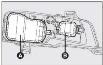
fig. 20
FOC0435m
To change the bulbs of the sidelights, direction indicators, low beams and fog lights it is necessary to remove the cover C releasing the catch D.
To change the bulbs of main beams and sidelights, remove the cover E operating the device F.
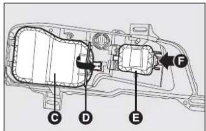
fig. 21
F0C0436m

After replacement, refit the covers correctly checking that they are properly secured.

DIPPED BEAM HEADLIGHTS fig. 22
Gas-filled filament lamps
To change the bulb, proceed as follows:
☐ remove the protective cover releasing the catch;
☐ release the bulb holder catch A;
☐ disconnect the electric connector B; remove the bulb C and replace it;
☐ fit the new bulb, making the tabs of the metallic part coincide with the grooves on the reflector, reconnect the electrical connector B then hook the bulb holder catch A;
□ refit the protective cover correctly.
Gas-discharge lamps (Xenon) (where provided)

WARNING
Due to high voltage, the bulb of (Xenon) gas-discharge
headlights must only be replaced by experts: danger of death! Contact Fiat Dealership.

MAIN BEAM HEADLIGHTS fig. 23
To change the bulb, proceed as follows:
☐ remove the protective cover releasing the catch;
☐ release the bulb holder catch A;
☐ disconnect the electric connector B; remove the bulb C and replace it;
☐ fit the new bulb, making the tabs of the metallic part coincide with the grooves on the reflector, reconnect the electrical connector B then hook the bulb holder catch A;
□ refit the protective cover correctly.
☐ remove the protective cover releasing the catch;
☐ release the bulb holder catch A;
☐ disconnect the electric connector B; remove the bulb C and replace it;
☐ fit the new bulb, making the tabs of the metallic part coincide with the grooves on the reflector, reconnect the electrical connector B then hook the bulb holder catch A;
□ refit the protective cover correctly.
MAIN BEAM HEADLIGHTS fig. 23
To change the bulb, proceed as follows:

DIRECTION INDICATORS
Front fig. 24
To change the bulb, proceed as follows:
☐ remove the protective cover releasing the catch;
□ turn the bulb holder A counterclockwise and remove it;
☐ remove the bulb B pushing it gently and turning counterclockwise;
☐ replace the bulb and then refit the bulb holder turning it clockwise, checking that it is secured correctly;
□ refit the protective cover correctly.
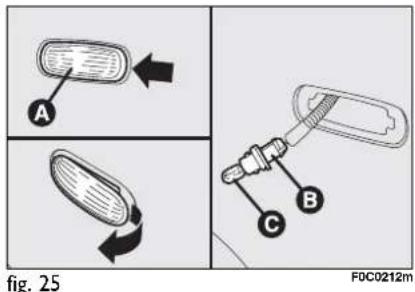
Side fig. 25
To change the bulb, proceed as follows:
☐ push the transparent cover A towards car running direction to compress the catch;
□ remove the unit;
□ turn the bulb holder B counterclockwise, remove the snap-fitted bulb C and replace it;
□ refit the bulb holder B in the transparent cover, then position the unit making sure the catch clicks into place.
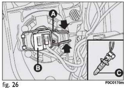
FRONT FOG LIGHTS (where provided) fig. 26
To change the bulb, proceed as follows:
☐ remove the protective cover releasing the catch;
☐ release the bulb holder catch A;
□ disconnect the electric connector B;
□ remove the bulb C and replace it;
☐ fit the new bulb, making the tabs of the metallic part coincide with the grooves on the reflector, reconnect the electrical connector B then hook the bulb holder catch A;
□ refit the protective cover correctly.
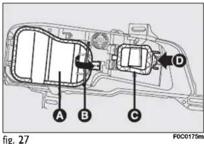
FRONT SIDELIGHTS
To replace the bulbs proceed as follows:
☐ remove the protective cover A and C-
fig. 27 releasing catch B and D re-
spectively;
☐ using the extension A-fig. 28 or D-fig. 29, turn the bulb holder B-fig. 28 or E-fig. 29 clockwise and counterclockwise and then withdraw it;
☐ remove the bulb C-fig. 28 or F-fig. 29 and replace it;
□ refit the bulb holder making sure the catch clicks into place; also check the proper bulb positioning looking at the lamp from outside;
□ refit the protective cover correctly.

REAR LIGHT UNITS (saloon versions)
To change the bulb, proceed as follows:
□ open the tailgate;
☐ from inside the boot, withdraw the connector A-fig. 30, loosen the 3 nuts B with the extension (where provided) used to tighten the wheel bolts (supplied with the tool kit) and remove the light unit.
IMPORTANT When subwoofer is located on the left side of the boot, to replace the rear light cluster contact Fiat Dealership.


3-door versions
To change the bulb, proceed as follows:
☐ press lamp holder catches A-fig. 31 outwards and remove it;
☐ remove bulbs slightly pushing them and turning counterclockwise.
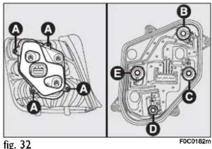
The bulbs are arranged inside the light unit as follows:
B: taillights;
C: direction indicators;
D: rear fog lights;
E: reversing lights;
F: taillights.
5-door versions
To change the bulb, proceed as follows:
☐ unloose the 4 screws A-fig. 32 and remove the bulb holder;
☐ remove bulbs slightly pushing them and turning counterclockwise.
The bulbs are arranged inside the light unit as follows:
B: taillights;
C: direction indicators;
D: taillights/rear fog lights;
E: reversing lights.

fig. 33
F0C0425m
REAR LIGHT UNITS
(Multi Wagon versions)
Tailgate light unit
To change the bulb, proceed as follows:
□ open the tailgate;
☐ push down cover A-fig. 33 and remove electric connector B-fig. 34;

fig. 34
☐ push the bulb holder side tabs A-
fig. 35 inwards to remove it;
☐ remove bulbs slightly pushing them and turning counterclockwise.

fig. 35
The bulbs are arranged inside the light unit as follows:
B: taillights;
C: reversing lights;
D: rear fog lights.

Side fixed light unit
To change the bulb, proceed as follows:
□ open the tailgate;
□ turn the handle A-fig. 36 to open the door B;
☐ hold the tongue C-fig. 37 and open the door for the rear light unit access;
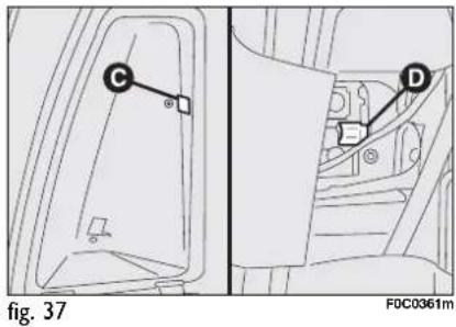
□ remove the electric connector D;
☐ push the bulb holder side tabs A-
fig. 38 inwards to remove it;
☐ remove bulbs slightly pushing them and turning counterclockwise.
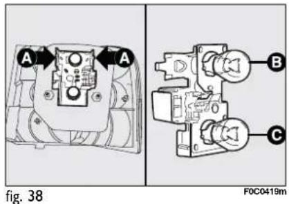
The bulbs are arranged inside the light unit as follows:
B: taillights/brake lights;
C: direction indicators.
ADDITIONAL BRAKING LIGHT (THIRD STOP)
IMPORTANT To replace the additional braking lights (third stop) contact a Fiat Dealership.
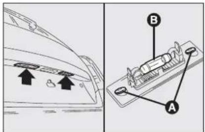
fig. 39

fig. 40
NUMBER PLATE LIGHTS
Saloon versions fig. 39
To change the bulb, proceed as follows:
☐ work in the points shown by the arrow and slacken the 2 cover fastening screws A;
□ change the bulb B releasing it from the side contacts and making sure the new bulb is correctly fastened between the contacts;
□ refit the cover.
Multi Wagon versions fig. 40
To change the bulb, proceed as follows:
☐ use the screwdriver supplied with the car to remove the transparent cover A as shown in the figure;
□ change the bulb B releasing it from the side contacts and making sure the new bulb is correctly fastened between the contacts;
□ refit the transparent cover.
IF AN INTERIOR LIGHT BURNS OUT
For the type of bulb and power rating, see "When needing to change a bulb".
FRONT CEILING LIGHT
Versions without Skywindow sunroof
To change the bulb, proceed as follows:
☐ press the catches A-fig. 41 and withdraw the plastic cover B;
□ slacken the 2 fastening screws A-fig. 42, then turn the 2 bulb holders B counterclockwise;
☐ remove the bulbs and replace them. To replace bulb C-fig. 42, release it from the side contacts making sure that the new bulb is correctly clamped between the contacts.

fig. 41

fig. 43

fig. 42

fig. 44
Versions with Skywindow sunroof
To change the bulbs, proceed as follows:
□ remove the front ceiling light A-fig. 43 pressing the plastic cover as shown by the arrows
□ disconnect electric connectors B-fig. 44 and C;


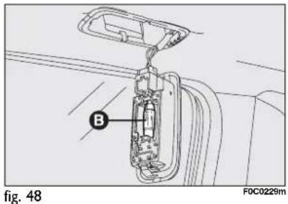

REAR CEILING LIGHT (where provided)
Versions without Skywindow sunroof
To change the bulb, proceed as follows:
☐ remove the light unit A-fig. 46 levering in the points shown by the arrows (on retaining tabs);
☐ replace the bulbs B releasing them from the side contacts making sure that the new bulb is correctly clamped between the contacts.
Versions with Skywindow sunroof
Versions with Skywindow sunroof are fitted with two rear ceiling lights.
To replace the bulbs proceed as follows:
☐ using the screwdriver provided in the kit, remove the cover A-fig. 47 in the point shown by the arrow;
□ replace the bulb B-fig. 48 releasing it from the side contacts making sure that the new bulb is correctly clamped between the contacts.
☐ slacken the 2 fastening screws A-fig. 45, then turn the 2 bulb holders B counterclockwise, remove the bulbs and replace them. To replace bulb C, release it from the side contacts making sure that the new bulb is correctly clamped between the contacts.

COURTESY MIRROR LIGHT (where provided)
To change the bulb, proceed as follows:
□ open the mirror cover A-fig. 49;
☐ remove the bulb B levering in the points shown by the arrows;
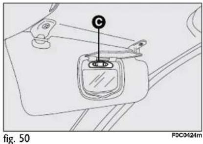
□ replace the bulb C-fig. 50 releasing it from the side contacts making sure that the new bulb is correctly clamped between the contacts.
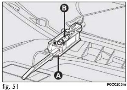
GLOVEBOX LIGHT fig. 51
To change the bulb, proceed as follows:
□ open the glovebox, then remove the light unit A;
☐ replace the bulb B releasing it from the side contacts making sure that the new bulb is correctly clamped between the contacts.

BOOT LIGHT
To change the bulb, proceed as follows:
□ open the tailgate;
☐ remove the bulb A-fig. 52 levering in the points shown by the arrow.
☐ open the protection B-fig. 53 and replace the snap-fitted bulb;
□ re-close the protective cover B on the lens;
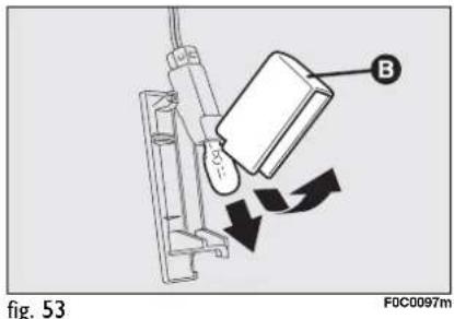
□ refit the light unit A-fig. 52 inserting it in its correct position firstly on one end and then on the other until it clicks into place.
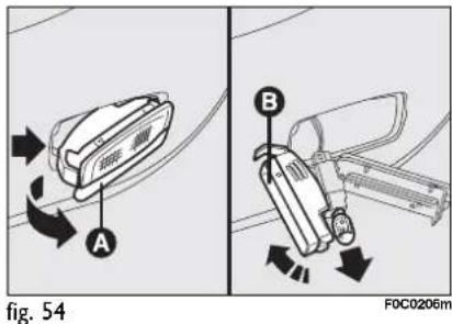
PUDDLE / DOOR LIGHTS fig. 54
To change the bulb, proceed as follows:
☐ open the door and remove the transparent cover A levering in the point shown by the arrow;
☐ open the protection B and replace the snap-fitted bulb;
□ re-close the protective cover B on the transparent cover A.
IF A FUSE BLOWS
GENERAL
The fuse is a protective device for the electric system: it comes into action (i.e. it cuts off) mainly due to a fault or improper action on the system.
When a device does not work, check the efficiency of its fuse: the conductor element A-fig. 55 must be intact. If not, replace the fuse with one of the same amp rating (same colour).
B: undamaged fuse
C: fuse with damaged filament.
To replace a fuse, use the pliers D hooked to the fusebox on the dashboard.
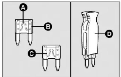
fig. 55
FOC0220m

Never replace a fuse with metal wires or anything else.

WARNING
Never replace a fuse with another with a higher amp DANGER OF FIRE.

WARNING
If a general fuse (MEGA-FUSE, MIDI-FUSE, MAXI-
FUSE) cuts in, do not attempt any repair and contact a Fiat Dealership. Before replacing a fuse, make sure the ignition key has been removed and that all the other services are switched off and/or disengaged.

WARNING
If a fuse blows again, contact a Fiat Dealership.
FUSE LOCATION
Fuses are grouped into four fuse boxes, to be found respectively on the dashboard, on the battery positive pole, next to the battery and in the boot (left-hand side).
Certain versions are also fitted with a single fuse set inside the engine compartment fuse box.
Fuse box on the dashboard fig. 57
To gain access to the fuses in the fuse box on the dashboard, open lid A-fig. 56.


fig. 57
F0C0266m
Fuse box next to the battery fig. 59
To gain access to the fuse box and to the single fuse next to the battery, press the retainers A-fig. 58 and remove the protection cover B.


fig. 59 F0C0151m
Fuse box on the battery positive pole fig. 61
To gain access to the fuses in the fuse box on the battery positive pole press the retainers A-fig. 60 and remove the protection cover B.

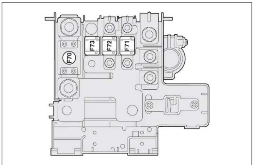
fig. 61
F0C0152m

Fuse box in the boot fig. 65
Saloon versions
To gain access to the fuses in the fuse box on the left side of the boot, open lid A-fig. 62 as shown in the figure.
Multi Wagon versions
To gain access to the fuses in the fuse box on the left side of the boot, proceed as follows:
□ turn the knob A-fig. 63 and open the lid B;
☐ hold the tab C-fig. 64 to open the second lid D and gain access to the fuse box.


fig. 65 F0C0531m
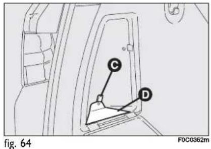
FUSE SUMMARY TABLE
| LIGHTS | FUSE | AMPERE | FIGURE |
| Right dipped beam headlight | F12 | 15 | 57 |
| Left dipped beam headlight | F13 | 15 | 57 |
| Right main beam headlight | F14 | 10 | 59 |
| Left main beam headlight | F15 | 10 | 59 |
| Front fog lights | F30 | 15 | 59 |
| Brake light/third stop light | F37 | 7.5 | 57 |
| Reversing light | F31 | 7.5 | 57 |
| Front/rear ceiling light/s | F32 | 10 | 57 |
| Door/puddle lights | F32 | 10 | 57 |
| +30 rear fog lights | F53 | 7.5 | 57 |
| RH/LH headlight fuse boxes(versions with gas-discharge headlights) | F37 | 7.5 | 57 |
| COMPONENTS | FUSE | AMPERE | FIGURE |
| Selespeed transmission pump (2.420v versions) | F05 (MAXI-FUSE) | 30 | 59 |
| Ignition switch | F03 (MAXI-FUSE) | 20 | 59 |
| Headlight aiming device | F13 | 15 | 57 |
| Climate control compressor | F19 | 7.5 | 59 |
| Anti-pollution sensor (versions with automatic two-zone climate control system)/headlight washer relay coil/Body Computer/Climate control system fan | F31 | 7.5 | 57 |
| Powered door mirrors control(movement, ideograph lighting) | F51 | 7.5 | 57 |
| + 30 Sound system/Connect-Navigator/Heating-climate control unit/EOBD system diagnostic socket/Volumetric-antiraising sensors/Alarm siren/Bluetooth system control unit | F39 | 10 | 57 |
| Rear window wiper seat warming relay coil | F52 | 15 | 57 |
| Left rear power window | F33 | 20 | 57 |
| Right rear power window | F34 | 20 | 57 |
| Rear heated window | F40 | 30 | 57 |
| Windscreen wiper/washer/rear window washer | F43 | 30 | 57 |
| Passenger compartment current outlet (saloon versions)/Current outlet (MultiWagon versions)/Cigar lighter | F44 | 20 | 57 |
| Door mirror demisting device/heated window nozzles | F41 | 7.5 | 57 |
| Cruise Control | F35 | 7.5 | 57 |
| Electric power steering control unit | F02 (MAXI-FUSE) | 70 | 59 |
| Engine compartment control unit | F70 (MEGA-FUSE) | 150 | 61 |
| Dashboard control unit | F71 (MIDI-FUSE) | 70 | 61 |
| +30 door electronic control unit (door lock actuators, dead lock, boot, rear heated window)/Trailer control unit, if any | F36 | 20 | 57 |
| Free | F38 | - | 57 |
| Headlight washer | F09 | 20 | 59 |
| Primary services (electronic injection) | F17 | 10 | 59 |
| Secondary services (electronic injection) | F11 | 15 | 59 |
| Water in diesel fuel filter sensor (Multijet versions)/flow meter (Multijet versions) | F35 | 7.5 | 57 |
| Front power window on driver side | F47 | 20 | 57 |
| Front power window on passenger side | F48 | 20 | 57 |
| Signal from switch on brake pedal for electronic control units | F35 | 7.5 | 57 |
| Instrument panel (key-operated positive) | F37 | 7.5 | 57 |
| Instrument panel (+30) | F53 | 7.5 | 57 |
| ABS / ASR / ESP control unit (yawing sensor with ESP) | F42 | 7.5 | 57 |
| ABS / ASR / ESP control unit | F01 (MAXI-FUSE) | 60 | 59 |
| Air bag control unit/OCS sensor (versions with rear side bags) | F50 | 7.5 | 57 |
| +30 Electronic injection system | F18 | 7.5 | 59 |
| Dashboard control unit | F72 (MIDI-FUSE) | 60 | 61 |
| Climate control fan | F08 (MAXI-FUSE) | 30 | 59 |
| Radiator fan (low speed - versions 1.416v, 1.616v, 1.816v, Multijet) | F06 (MAXI-FUSE) | 30 | 59 |
| Radiator fan (high speed - versions 1.416v, 1.616v, 1.816v, Multijet) | F07 (MAXI-FUSE) | 50 | 59 |
| Fan and radiator (versions 2.420v) | F06 (MAXI-FUSE) | 60 | 59 |
| Horn | F10 | 15 | 59 |
| Fuel pump | F21 | 15 | 59 |
| Electronic injection primary services (petrol versions) | F22 | 15 | 59 |
| Electronic injection system/Selespeed system(2.4 20v versions)/Radiator fan control unit(2.4 20v versions) (key-operated positive) | F16 | 7.5 | 59 |
| Skywindow sunroof curtain | F45 | 20 | 57 |
| Skywindow sunroof | F46 | 20 | 57 |
| Additional heater (Multijet versions) | F73 (MIDI-FUSE) | 50 | 61 |
| Glow plug warming (Multijet versions) | F04 (MAXI-FUSE) | 50 | 59 |
| Free | F20 | - | 59 |
| Electronic injection primary services (Multijet versions) | F22 | 20 | 59 |
| +30 Selespeed | F23 | 15 | 59 |
| Electric power steering (key-operated positive) | F24 | 7.5 | 59 |
| Radio external amplifier | F54 | 25 | 65 |
| Driver's seat warming | F57 | 10 | 65 |
| Front passenger's seat warming | F67 | 10 | 65 |
| Steering wheel controls, Connect/Navigator, Parking sensors,Rain/daylight sensor, Central console control panel,Heating/climate control unit, Bluetooth system control unit,Ideograph lighting, Set of switches for light control andmenu access-setting, Volumetric and antiraising sensor deactivation buttons, Front ceiling light,Sunroof controls (key-operated positive) | F49 | 7.5 | 57 |
IF THE BATTERY IS FLAT
IMPORTANT The battery charging procedure is described only for information purposes. This operation should be carried out by Fiat Dealership.
Charging should be slow at a low amp rating for 24 hours. Charging for a longer time may damage the battery.
Charge the battery as follows:
□ disconnect battery negative terminal;
□ connect the charger cables to the battery terminals, observing the poles;
□ turn on the charger;
☐ when you have finished, turn the charger off before disconnecting the battery;
□ reconnect battery negative terminal.
IMPORTANT Where relevant, switch the electronic car alarm off with remote control (see "Alarm" in section "Dashboard and controls").

WARNING
The liquid contained in the battery is poisonous and corrosive. Avoid contact with the skin or eyes. The battery should be charged in a well ventilated place, away from naked flames or possible sources of sparks: danger of explosion and fire.

WARNING
Do not attempt to charge a frozen battery: it must firstly be thawed, otherwise it may burst. If freezing has occurred, the battery should be checked by skilled personnel to make sure that the internal elements are not damaged and that the body is not cracked, with the risk of leaking poisonous and corrosive acid.
JACKING THE CAR
If the car is to be lifted, go to a Fiat Dealership which is equipped with the arm hoist or workshop lift.
Jack up the car only by positioning the jack arms or the shop jack in the points shown in fig. 66.

fig. 66
FOC0247m
TOWING THE CAR
The tow ring provided with the car is housed in the tool box under the boot mat.
TOW RING HOOKING
Proceed as follows:
☐ release the cap operating the tab A-fig. 67-68;
☐ take the tow hook B from its support;
□ tighten the ring on the rear or front threaded pin.

fig. 67
F0C0384m

fig. 68
F0C0387m
TOWING SELESPEED VERSIONS
For versions with Selespeed gearbox, make sure that it is in neutral N checking that the car moves when pushed) and proceed as for towing a normal car with mechanical gearbox following the instructions given previously.
If setting to neutral is not possible, do not tow the car. Contact a Fiat Dealership.

WARNING
Before starting to tow, turn the ignition key to MAR and
then to STOP. Do not remove the key. If the key is removed, the steering lock engages automatically resulting in the impossibility to steer the wheels.

WARNING
When towing, remember that without the help of the servobrake and power steering, a greater effort is required on the pedal and steering wheel. Do not use flexible cables for towing and avoid jerks. During towing operations make sure that fastening the joint to the car does not damage the components in contact with it. When towing the car, you must comply with the specific traffic regulations regarding the tow ring and how to tow on the road.

WARNING
Do not start the engine when towing the car.
FIRE EXTINGUISHER (where provided)
It is located on the right side of the boot; position varies according to 3 fig. 69 or 5-door versions fig. 70.
The fire extinguisher has a reference mark (5p for 5-door versions or 3p for 3-door versions) for the extinguisher correct positioning on the retaining bracket.

natural_image
Line drawing of a fire extinguisher assembly (no text or symbols)fig. 69
FOC0331m

fig. 71
F0C0344m
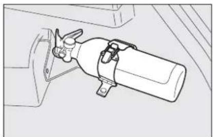
natural_image
Technical line drawing of a mechanical assembly with no visible text or symbolsfig. 70
F0C0343m
To use the fire extinguisher, proceed as follows: release the catch A-fig. 71 and open the tabs B.
IMPORTANT In addition to the fire extinguisher, it is also wise to keep a first-aid kit and a blanket in the car.
CARRAMUTENANCE
SCHEDULED SERVICING 210
SERVICE SCHEDULE.... 211
ANNUAL INSPECTION SCHEDULE.... 213
ADDITIONAL CHECKS.... 213
CHECKING FLUID LEVELS.... 216
AIR FILTER 225
POLLEN FILTER 225
DIESEL FUEL FILTER 225
BATTERY....226
WHEELS AND TYRES 229
RUBBER HOSES.... 230
WINDSCREEN/REAR WINDOW WIPERS.... 231
BODYWORK 233
INTERIORS 235
SCHEDULED SERVICING
Correct maintenance is essential for ensuring long car life under the best conditions.
This is why Fiat has programmed a series of checks and maintenance operations every 30.000 km.
It is however important to remember that scheduled servicing does not completely cover all the car's requirements: also in the initial period before 30.000 km service coupon and later, between one coupon and another, ordinary care is still required such as for example routine check and topping up the level of fluids, tyre pressure check, etc...
IMPORTANT The Scheduled Servicing coupons are specified by the Manufacturer. The failure to have them carried out may invalidate the warranty.
Scheduled Servicing is performed by all Fiat Dealership, at pre-established times. If during each operation, in addition to the ones programmed, the need arises for further replacements or repairs, these may be carried out only with the explicit agreement of the Customer.
IMPORTANT You are advised to contact Fiat Dealership in the event of any minor operating faults, without waiting for the next service coupon.
If your car is used frequently for towing, the interval between one service coupon and the other must be reduced.
SERVICE SCHEDULE
| Thousands of km | 30 60 | 90 | 120 | 150 | 180 | |||
| Check tyre conditions/wear and adjust pressure if required | ● | ● | ● | ● | ● | ● | ||
| Check light system operation (headlights, direction indicators, hazard lights, boot lights, passenger compartment lights, glovebox lights, warning lights, etc.) | ● | ● | ● | ● | ● | ● | ||
| Check windscreen wiper/washer operation, adjust nozzles if required | ● | ● | ● | ● | ● | ● | ||
| Check windscreen/rear window blade position/wear | ● | ● | ● | ● | ● | ● | ||
| Check front disk brake pad conditions and wear and wear indicator operation | ● | ● | ● | ● | ● | ● | ||
| Check rear disk brake pad conditions and wear | ● | ● | ● | ● | ● | ● | ||
| Sight inspect the conditions of: body external parts, underbody protection, pipes and hoses (exhaust - fuel - brakes), rubber parts (boots, sleeves, bushes, etc.) | ● | ● | ● | ● | ● | ● | ||
| Check cleanness of locks, bonnet and boot and lever cleanness, and lubrication | ● | ● | ● | ● | ● | ● | ||
| Check and top up, if required, fluid levels (brakes/hydraulic clutch, windscreen/rear window washer, battery, engine coolant, etc.) | ● | ● | ● | ● | ● | ● | ||
| Check and adjust handbrake lever stroke, if required | ● | ● | ● | |||||
| Sight inspect accessory drive belt conditions (excluding 1.616V version) | ● | ● | ||||||
| Sight inspect accessory drive belt conditions (1.616V version) | ● | ● | ||||||
| Check and adjust tappet clearance (1.9 Multijet 8V version) | ● | ● | ● | |||||
| Check and adjust tappet clearance (1.6 16V only version) | ● | |||||||
| Check exhaust emissions (petrol versions) | ● | ● | ● | ● | ● | ● | ||
| Check exhaust emissions/smoke (Multijet versions) | ● | ● | ● | ● | ● | ● |
Thousands of km 30 60 90 120 150 180
| Check timing belt conditions(1.616V excluding version) | ● | ● | ||||
| Check timing belt conditions(1.616V version) | ● | ● | ||||
| Check engine control system operation(through diagnostic socket) | ● | ● | ● | ● | ● | ● |
| Replace accessory drive belt/s(excluding 1.616V version) | ● | |||||
| Replace accessory drive belt/s (1.616V version) | ● | |||||
| Replace timing belt(excluding Multijet and 1.616V versions) (*) | ● | |||||
| Replace timing belt(Multijet and 1.616V versions) (*) | ● | |||||
| Change spark plugs (1.616V version) | ● | ● | ● | |||
| Change spark plugs (petrol versions - excluding 1.616V) | ● | ● | ● | ● | ● | ● |
| Replace diesel fuel filter (Multijet versions) | ● | ● | ● | |||
| Replace air cleaner cartridge | ● | ● | ● | |||
| Change engine oil and oil filter(petrol versions) (or every year) | ● | ● | ● | ● | ● | ● |
| Change engine oil and oil filter(Multijet versions without DPF) (or every 2 years) | ● | ● | ● | ● | ● | ● |
| Change engine oil and oil filter(Multijet versions with DPF) (**) | ||||||
| Change brake fluid (or every 2 years) | ● | ● | ● | |||
| Change pollen filter (or every year) | ● | ● | ● | ● | ● | ● |
(*) Regardless of the km covered, the timing belt shall be replaced every 3 years for particularly demanding use (cold climates, driving in the city, idling for a long time) or in any case every 5 years
(**) Engine oil and oil filter shall be changed when the relevant warning light/message on the display turn on and in any case every 2 years.
ANNUAL INSPECTION SCHEDULE
For cars with an annual mileage of below 30.000 km (for example about 15.000 km) the following yearly inspection programme is advised:
☐ check tyre conditions/wear and adjust pressure if required (including the space-saver spare wheel);
☐ check light system operation (headlights, direction indicators, hazard lights, boot lights, passenger compartment lights, glovebox light, warning lights, etc.);
☐ check windscreen wiper/washer operation, adjust nozzles;
☐ check windscreen/rear window blade position/wear;
☐ check front disk brake pad conditions and wear;
☐ sight inspect the conditions of: engine, gearbox, transmission, pipes and hoses (exhaust - fuel - brakes), rubber parts (boots, sleeves, bushes, etc.) fuel and brake system hoses;
☐ check cleanness of bonnet and boot locks, and lever cleanness and lubrication
☐ check battery charge (by optical depth gauge);
☐ visual check on various drive belt conditions;
☐ check and top up fluid levels (engine coolant, brakes, windscreen washer, battery, etc.);
☐ change engine oil and oil filter, if required (Multijet versions);
□ replace pollen filter.
ADDITIONAL CHECKS
Every 1,000 km or before long journeys, check and top up if required:
□ engine coolant fluid level;
□ brake fluid level;
□ windscreen washer fluid level;
□ tyre pressure and conditions.
Every 3,000 km check and top up if required: engine oil level.
You are recommended to use FL Selenia products, designed and produced specifically for Fiat cars (see table "Capacities" in section "Technical specifications").
IMPORTANT - Engine oil (petrol and Multijet versions without DPF)
Should prevailing use of the car be under one of the following specially heavy conditions:
□ trailer or caravan towing;
□ dusty roads;
☐ short distances (less than 7-8 km) repeated and with external temperatures below zero;
☐ frequently idling engines or long distance low speed driving (e.g. taxis or door-to-door deliveries) or in case of a long term inactivity;
replace engine oil more frequently than required on "Service schedule".
IMPORTANT - Engine oil (Multijet versions with DPF)
Engine oil and oil filter shall be changed when the relevant warning light, together with the message on the display, turn on (see section "Warning lights and messages") or in any case every 2 years.
Should prevailing use of the car be in the city, engine oil will waste faster.
IMPORTANT - Air cleaner
If the car is used on dusty roads change the air cleaner more frequently than the indications in the "Service schedule".
If in doubt as to how often the engine oil and air cleaner should be changed according to how you use the car, contact a Fiat Dealership.

Oil topping up, even significant ones, do not replace the engine oil change procedure required when warning light
turns on. Engine oil shall be changed at a Fiat Dealership that will also turn off the warning light on the instrument panel.
IMPORTANT - Pollen filter
If the car is used frequently in dusty or heavily polluted environments it is advisable to replace the filtering element more frequently; in particular it should be replaced if a reduction of the amount of air admitted to the passenger compartment is noted.
IMPORTANT - Diesel filter
The possibility of topping up with diesel fuel not complying with EN590 European Norm might make it necessary to replace the filter more frequently than indicated in the “Service Schedule”.
IMPORTANT - Battery
The charge in the battery should be checked at the start of winter to limit the risk of electrolyte freezing.
This check should be carried out more frequently if the car is used mainly for short trips, or if it is fitted with accessories that permanently absorb electricity even with the ignition key removed, especially in the case of after market accessories. If the car is used in hot climates or particularly harsh conditions it is wise to check the level of the battery fluid (electrolyte) more frequently than specified in the "Service schedule".

Car maintenance should be entrusted to Fiat Dealership. For routine and minor maintenance operations you wish to carry out yourself, always make sure you have the proper equipment, genuine Fiat spare parts and the necessary fluids; do not however carry out these operations if you have no experience.
CHECKING FLUID LEVELS
IMPORTANT When topping up take care not to confuse the various types of fluids: they are all incompatible with one another and could seriously damage the car.
IMPORTANT Never smoke while working in the engine compartment; gas and inflammable vapours may be present, with the risk of fire.

fig. 1 - 1.416V version
1 Engine oil - 2 Battery - 3 Brake fluid - 4 Windscreen/rear window/headlight washer fluid - 5 Engine coolant

fig. 2 - 1.616V version
1 Engine oil - 2 Battery - 3 Brake fluid - 4 Windscreen/rear window/headlight washer fluid - 5 Engine coolant
1 Engine oil - 2 Battery - 3 Brake fluid - 4 Windscreen/rear window/headlight washer fluid - 5 Engine coolant - 6 Sele-speed transmission oil (where provided)

fig. 3 - 1.816V version

fig. 4 - 2.420V version
1 Engine oil - 2 Battery - 3 Brake fluid - 4 Windscreen/rear window/headlight washer fluid - 5 Engine coolant
1 Engine oil - 2 Battery - 3 Brake fluid - 4 Windscreen/rear window/headlight washer fluid - 5 Engine coolant
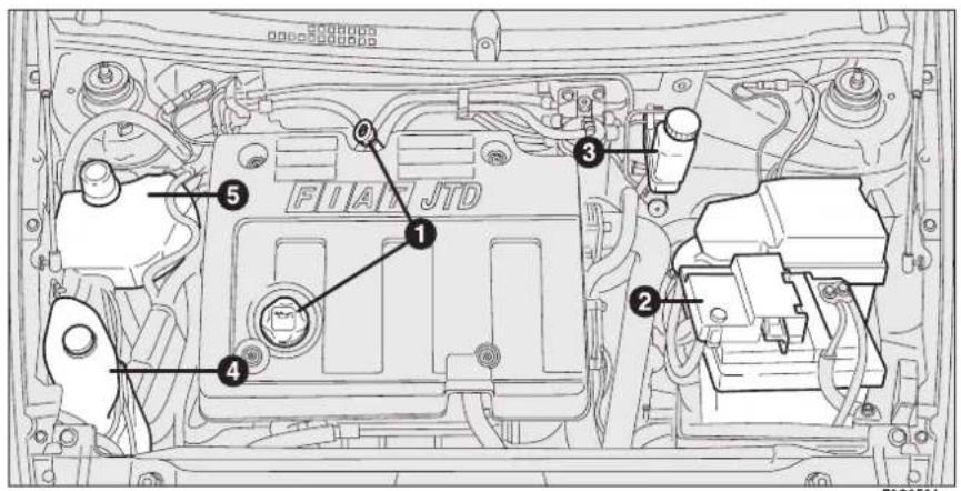
fig. 5 - 1.9 Multijet 8V versions

fig. 6 - 1.9 Multijet 16V versions

fig. 7 - 1.416V version

fig. 8 - 1.816V version
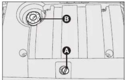
fig. 9 - 1.9 Multijet 8V version
ENGINE OIL fig. 7-8-9-10-11-12
Checking engine oil
Check the oil level a few minutes (about 5) after the engine has stopped, with the car parked on level ground.
Remove the dipstick A and clean it, put it back in completely, remove it and check that the level is within the MIN and MAX marks on the dipstick. The interval between the MIN and MAX marks corresponds to about one litre of oil.
Topping up engine oil
If the oil level is near or even below the MIN mark, add oil through the filler neck B, until reaching the MAX mark.
Oil level shall never exceed the MAX mark.
IMPORTANT If a routine check reveals that the oil level is above the MAX mark, contact Fiat Dealership to have the correct level restored.
IMPORTANT After adding or changing the oil, let the engine turn over for a few seconds and wait a few minutes after turning it off before you check the level.
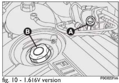
Engine oil consumption
Max engine oil consumption is usually 400 grams every 1000 km.
When the car is new, the engine needs to run in, therefore the engine oil consumption can only be considered stabilised after the first 5000 - 6000 km.
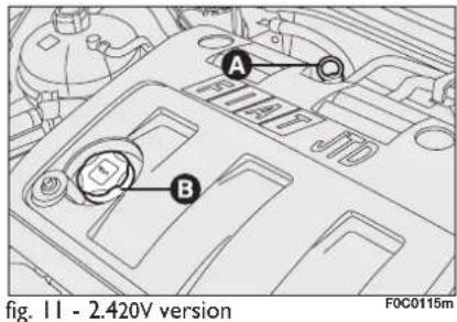
IMPORTANT The oil consumption depends on driving style and the conditions under which the car is used.
IMPORTANT Do not add oil with specifications other than that already in the engine.
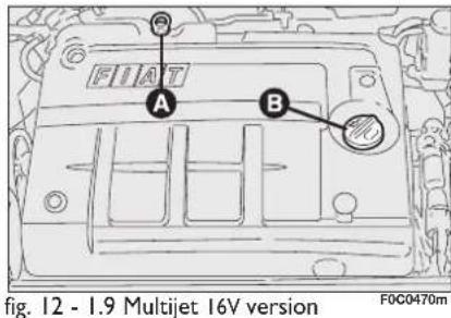

WARNING
When the engine is hot, take care when working inside the
engine compartment to avoid burns. Remember that when the engine is hot, the fan may cut in: danger of injury. Scarves, ties and other loose clothing might be pulled by moving parts.

Used engine oil and filter contain harmful substances for the environment. Contact Fiat Dealership to have the oil
and filter changed.
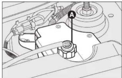
natural_image
Mechanical assembly diagram showing engine components and a labeled component (no text or symbols present)fig. 13
F0C0121m
HYDRAULIC SYSTEM OIL FOR ACTUATING SELESPEED GEARBOX (where provided)
fig. 13
The oil should be checked with the car on a level surface and with the engine stopped and cold.
To check the level, proceed as follows:
□ turn the ignition key to MAR;
☐ disconnect the breather tube and remove the cap A checking that the level corresponds with the MAX mark on the reservoir;
☐ if the oil is below the MAX mark, top up to reach the correct level;
□ after refitting the cap, insert the breather tube firmly on the cap spout and turn the ignition key to STOP.
IMPORTANT Do not add oil into the circuit tank having different specifications from that already existing.

Used gearbox oil contains dangerous substances for the environment. For changing the oil we advise contacting
Fiat Dealership, which is equipped for disposing of used oil respecting the nature and the law.

fig. 14 - 1.416V version

fig. 15 - 1.416V - 1.816V - 2.420V version
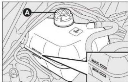
fig. 16 - 1.9 Multijet version
ENGINE COOLANT FLUID
fig. 14-15-16
The coolant level shall be checked with cold engine and shall not be lower than the MIN mark on the reservoir.
If the level is low, pour slowly a mixture of 50% distilled water and 50% PARAFLU UP of the FL Selenia through the filler neck A.
A 50-50 mixture of PARAFLU UP and distilled water gives freeze protection to -35^ .

The cooling system uses PARAFLU UP antifreeze. Do not add fluid having different specifications from that already existing. PARAFLU UP cannot be mixed with other types of fluids. Should other fluids be added, do not start the engine and contact Fiat Dealership as soon as possible.

WARNING
Do not remove the reservoir cap when the engine is hot: you risk scalding yourself. The cooling system is pressurised. If necessary, replace the cap only with another genuine one, otherwise system efficiency could be compromised.

WINDSCREEN/REAR WINDOW/HEADLIGHT WASHER FLUID fig. 17-18
To top up, open the cap A and then pour a mixture of water and TUTELA PRO-FESSIONAL SC 35, in the following concentrations:
☐ 30% TUTELA PROFESSIONAL SC 35 and 70% water in summer;
☐ 50% TUTELA PROFESSIONAL SC 35 and 50% water in winter.
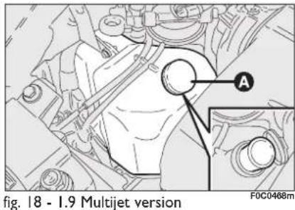
In case of temperatures below -20^ , use undiluted TUTELA PROFESSIONAL SC 35 fluid.
Check level through the reservoir.
For versions fitted with headlight washer, remove the filter and the relevant dipstick. Use the dipstick to check the fluid level inside the reservoir.

WARNING
Do not travel with the windscreen washer reservoir empty. The windscreen washer is fundamental for improving visibility.

WARNING
Certain commercial additives for windscreen washers are inflammable. The engine compartment contains hot components which may set it on fire.

BRAKE FLUID fig. 19
Unscrew cap A and check that the fluid level in the reservoir is at maximum.
Fluid level in the reservoir shall not exceed the MAX mark.
If fluid has to be added, it is suggested to use the brake fluid in table "Fluids and lubricants" (see chapter "Technical characteristics").
NOTE Clean accurately the tank cap A and the surrounding surface.
At plug opening, pay maximum attention in order to prevent any impurities from entering the tank.
For topping up, always use a funnel with integrated filter with mesh equal to or lower than 0.12 mm.
IMPORTANT Brake fluid absorbs moisture. For this reason, if the car is mainly used in areas with a high degree of atmospheric humidity, the fluid should be replaced at more frequent intervals than specified in the "Service schedule".

Prevent brake fluid, which is highly corrosive, from coming into contact with painted parts. Should it happen, imply wash with water.

WARNING
Brake fluid is poisonous and highly corrosive. In the event mental contact, wash the parts immediately with neutral and water, then rinse thor-Call the doctor immediately is swallowed.

WARNING
Symbol Ⓞ on the container indicates synthetic brake flu-
id, distinguishing it from the mineral kind. Using mineral fluids irreversibly damages the special braking system rubber seals.
AIR FILTER
Air filter replacement shall be carried out at a Fiat Dealership.
POLLEN FILTER
Pollen filter replacement shall be carried out at a Fiat Dealership.
DIESEL FUEL FILTER
DRAINING THE CONDENSE (Multijet versions)
IMPORTANT The presence of water in the fuel circuit can severely damage the whole injection system and make the engine misfire. If the warning light 📋 turns on (together with the message on the display), contact a Fiat Dealership as soon as possible to have the bleeding operation carried out.
BATTERY
The battery is of the "Limited maintenance" type: under normal conditions of use the electrolyte does not need topping up with distilled water.
Contact Fiat Dealership to have the battery checked/replaced.
CHECKING THE CHARGE fig. 20
The battery charge may be checked through the indicator A (where required) set on the battery cover and acting according to the colour the indicator shows.

fig. 20
F0C0506m
Should the battery be not fitted with battery charge inspection device (optical electrolyte indicator), inspection operations shall be carried out by skilled personnel only.
Refer to the table below or to the label B on the battery.

WARNING
The liquid in the battery is poisonous and corrosive.
Avoid contact with eyes and skin. Do not bring naked flames or possible sources of sparks near the battery: risk of fire and explosion.

WARNING
Running the battery with low fluid level can damage
the battery beyond repair and could also cause its explosion.
| Bright white colour | Top up electrolyte | Contact Fiat Dealership |
| Dark colour without green area in the centre | Low charge level | Charge the battery (advisable to contact Fiat Dealership) |
| Dark colour with green area in the centre | Electrolyte level and charge sufficient | No action |
CHANGING THE BATTERY
If required, replace the battery with a genuine spare part having the same specifications.
If a battery with different specifications is fitted, the service intervals given in the "Service schedule" in this section will no longer be valid.
Refer to the instructions provided by the battery manufacturer.

Incorrect fitting of electrical and electronic accessories can seriously damage the car. If after buying the car, you want to install electric accessories which require permanent electric supply (alarm, free-hand phone kit, etc.) contact Fiat Dealership whose qualified personnel, in addition to suggesting the most suitable devices, will evaluate the overall electric absorption, checking whether the car electric system is capable of withstanding the load required, or whether it should be integrated with a more powerful battery.

Batteries contain substances that are very harmful for the environment. You are advised to have the battery changed at a Fiat Dealership, which is properly equipped for disposing of used batteries respecting nature and the law.

WARNING
If the car is left inactive for long periods at cold, remove the battery and store it in a warm place to prevent freezing.

WARNING
When working on the bat- tery or near it, always wear the proper goggles.
USEFUL ADVICE
FOR LENGTHENING THE LIFE OF YOUR BATTERY
To avoid draining your battery and lengthen its life, observe the following indications:
□ when you park the car, ensure the doors, tailgate and bonnet are closed properly;
☐ the ceiling lights must be off. The car is however provided with an automatic system for switching off internal lights;
☐ do not keep accessories (e.g.: sound system, hazard lights, etc.) switched on for a long time when the engine is not running;
☐ before performing any operation on the electrical system, disconnect the battery negative cable;
☐ battery terminals shall always be perfectly tightened.
IMPORTANT A battery which is kept at a charge of less than 50% (optical indicator with dark colour without green area in the middle) for any length of time will be damaged by sulphation leading to a reduction in cranking power.
Moreover, this might lead to a higher risk of the battery electrolyte freezing (this may even occur at -10^ ). If the car is inactive for a long period of time, refer to “Car inactivity”, in section “Correct use of the car”.
If after buying the car, you want to install electric accessories which require permanent electric supply (alarm, etc.) contact Fiat Dealership whose qualified personnel, in addition to suggesting the most suitable devices, will evaluate the overall electric absorption, checking whether the car's electric system is capable of with-standing the load required, or whether it should be integrated with a more powerful battery.
In fact, since these devices continue absorbing energy even when the ignition key is off, they gradually run down the battery.
The total intake of these systems (factory and after-market) must be less than 0,6 mA x Ah (of the battery) as shown in the following table:
| Battery | Maximum admitted stand-by intake |
| 40 Ah | 24 mA |
| 50 Ah | 30 mA |
| 60 Ah | 36 mA |
WHEELS AND TYRES
Check the pressure of each tyre, including the spare, every two weeks and before long journeys. The pressure should be checked with the tyre rested and cold.
For the correct tyre inflation pressure, see "Wheels" in "Technical specifications" section.
Incorrect pressure causes abnormal tyre wear fig. 21:
A: normal pressure: tread evenly worn.
B: low pressure: tread particularly worn at the edges.
C: high pressure: tread particularly worn in the centre.
Tyres must be replaced when the tread wears down to 1.6 mm. In any case, comply with the laws in the country where the car is being driven.

fig. 21
F0C0101m
IMPORTANT NOTES
☐ As far as possible, avoid sharp braking and screech starts, etc. Be careful not to hit the kerb, potholes or other obstacles hard. Driving for long stretches over bumpy roads can damage the tyres;
☐ Periodically check that the tyres have no cuts in the side wall, abnormal swelling or irregular tyre wear. If any of these occur, have the car seen to at a Fiat Dealership;
☐ avoid overloading the car when travelling: this may cause serious damage to the wheels and tyres;
☐ if a tyre is punctured, stop immediately and charge it to avoid damage to the tyre, the rim, suspensions and steering system;
☐ Tyres age even if they are not used much. Cracks in the tread rubber are a sign of ageing. In any case, if the tyres have been on the car for over 6 years, they should be checked by specialised personnel, to see if they can still be used. Also remember to check the space-saver spare wheel;
☐ In the case of replacement, always fit new tyres, avoiding those of dubious origin;
☐ If a tyre is changed, also change the inflation valve;
☐ To allow even wear between the front and rear tyres, it is advisable to change them over every 10-15 thousand kilometres, keeping them on the same side of the car so as to not reverse the direction of rotation.
☐ if a tyre is punctured, stop immediately and charge it to avoid damage to the tyre, the rim, suspensions and steering system;
☐ Tyres age even if they are not used much. Cracks in the tread rubber are a sign of ageing. In any case, if the tyres have been on the car for over 6 years, they should be checked by specialised personnel, to see if they can still be used. Also remember to check the space-saver spare wheel;
☐ In the case of replacement, always fit new tyres, avoiding those of dubious origin;
☐ If a tyre is changed, also change the inflation valve;
☐ To allow even wear between the front and rear tyres, it is advisable to change them over every 10-15 thousand kilometres, keeping them on the same side of the car so as to not reverse the direction of rotation.

WARNING
Remember that road holding depends also on the correct tyre inflating pressure.

WARNING
Do not cross switch the tyres, moving them from the right of the car to the left and vice versa.
RUBBER HOSES
As far as the brake system and fuel rubber hoses are concerned, carefully follow the "Service schedule" in this section.
Indeed ozone, high temperatures and prolonged lack of fluid in the system may cause hardening and cracking of the hoses, with possible leaks. Careful control is therefore necessary.

WARNING
If the pressure is too low the tyre overheats and this can cause it serious damage.

WARNING
Never submit alloy rims to repainting treatments requiring to use temperatures exceeding 150°C since the mechanical properties of the wheels could be impaired.
WINDSCREEN/ REAR WINDOW WIPERS
BLADES
Periodically clean the rubber part using special products; TUTELA PROFES- SIONAL SC 35 is recommended.
If the rubber blades are bent or worn they should be replaced. In any case they should be changed once a year.
A few simple notions can reduce the possibility of damage to the blades:
☐ if the temperature fall below zero, make sure that ice has not frozen the rubber against glass. If necessary, thaw using an antifreeze product;
☐ remove any snow from the glass: in addition to protecting the blades, this prevents effort on the motor and overheating;
☐ do not operate the windscreen and rear window wipers on dry glass.

fig. 22

natural_image
Technical line drawing of a mechanical component with an inset view labeled 'A' (no text or symbols present)fig. 23
Changing the windscreen wiper blades
Proceed as follows:
☐ raise the windscreen wiper arm A-fig. 22 and position the blade so that it forms an angle of 90^ with the arm;
☐ press tab B of the coupling spring and remove the blade to be replaced from the arm A;
☐ fit the new blade by inserting the tab into the special slot in the arm. Make sure it is properly locked into place.
For certain versions, to replace the blades proceed as follows:
☐ raise the windscreen wiper arm and position the blade so that it forms an angle of 90^ with the arm;
☐ press tabs A-fig. 23 (set aside the blade) and remove the blade to be replaced from the arm;
☐ fit the new blade and check it is properly locked into place.

WARNING
Driving with worn wiper blades is a serious hazard, visibility is reduced in bad

Changing the rear window blade
Proceed as follows:
☐ raise the cover A-fig. 24 and remove the arm from the car, slackening the nut B that fastens it to the pivot pin;
☐ fit the new arm, positioning it correctly, and fully tighten the nut;
□ lower the cover.
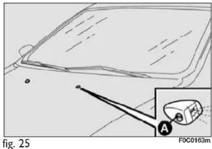
natural_image
Diagram showing a vehicle's roof and side profile with an inset view of a vehicle labeled 'A' (no text or symbols on the diagram itself)SPRAY NOZZLES
Windscreen wiper fig. 25
If the jet of fluid is inadequate, firstly check that there is fluid in the reservoir: see "Checking fluid levels" in this section).
Then check that the nozzle holes are not clogged, if necessary use a needle.
The windscreen jets are directed by adjusting the angle of the nozzles: turn the nozzle cylinder by inserting a screwdriver in A.
Fluid jets shall be directed at about 1/3 height from the window upper edge.
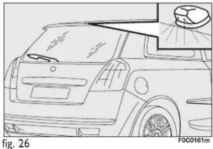
natural_image
Line drawing of a car front view with no visible text or symbols
natural_image
Technical line drawing of a car interior with lane markings and an inset detail (no text or symbols)Rear window wiper fig. 26-27
Rear window washer jets can be adjusted in the same way.
The nozzle holder is on the rear window.
BODYWORK
PROTECTION FROM ATMOSPHERIC AGENTS
The main causes of corrosion are the following:
□ atmospheric pollution;
☐ salty air and humidity (coastal areas, or hot humid climates);
□ seasonal environment conditions.
Not to be underestimated is also the abrasive action of wind-borne atmospheric dust and sand and mud and gravel raised by other cars.
On your car, Fiat implemented the best manufacturing technologies to effectively protect the bodywork against corrosion.
These include:
□ Painting products and systems which give the car particular resistance to corrosion and abrasion;
☐ Use of galvanised (or pretreated) steel sheets, with high resistance to corrosion;
Spraying the underbody, engine compartment, wheelhouse internal parts and other parts with highly protective wax products;
Spraying of plastic parts, with a protective function, in the more exposed points: underdoor, inner fender parts, edges, etc.;
☐ Use of “open” boxed sections to prevent condensation and pockets of moisture from triggering rust inside.
BODY AND UNDERBODY WARRANTY
Your car is covered by warranty against perforation due to rust of any original element of the structure or body. For the general terms of this warranty, refer to the Fiat Warranty booklet.
ADVICE FOR PRESERVING THE BODYWORK
Paint
Paintwork does not only serve an aesthetic purpose, but also protects the underlying sheet metal.
In the case of deep scrapes or scores, you are advised to have the necessary touching up carried out immediately to avoid the formation of rust. Use only original paint products for touching up (see "Bodywork paint identification plate" in section "Technical specification").
Normal paint maintenance consists in washing at intervals depending on the conditions and environment of use. For example, in highly polluted areas, or if the roads are sprayed with salt, it is wise to wash the car more frequently.
To correctly wash the car:
☐ remove the aerial from the roof to prevent damage to it if the car is washed in an automatic system;
☐ wash the body using a low pressure jet of water;
☐ wipe a sponge with a slightly soapy solution over the bodywork, frequently rinsing with the sponge;
☐ rinse well with water and dry with a jet of air or a chamois leather.
When drying, take particular care with the less visible parts like door surrounds, bonnet and around the headlights where water may stagnate. The car should not be taken to a closed area immediately, but left in the open so that residual water can evaporate.
Do not wash the car after it has been left in the sun or with the bonnet hot: this may alter the shine of the paintwork.

Detergents cause water pollution. Therefore the car should be washed in areas equipped for collecting and purifying the liquid used in the washing process.
Exterior plastic parts must be cleaned in the same way as the rest of the car.
Where possible, do not park under trees; the resinous substance many species release give the paint a dull appearance and increase the possibility of triggering rust processes.
IMPORTANT Bird droppings must be washed off immediately and thoroughly as the acid they contain is particularly aggressive.
Front headlights
IMPORTANT Never use aromatic substances (e.g.: petrol) or ketones (e.g.: acetone) for cleaning front headlight plastic lens.
Windows
Use specific window cleaner products. Use also clean cloths to avoid scratching the glass or damaging the transparency.
IMPORTANT The inside of the rearscreen should be wiped gently with a cloth in the direction of the filaments to avoid damaging the heating device.
Engine compartment
At the end of the winter the engine compartment should be carefully washed, without directing the jet against electronic control units. Contact a specialised workshop to have this done.
IMPORTANT The car should be washed with the engine cold and the ignition key at STOP. After washing make sure that the various protections (e.g. rubber caps and various covers) have not been damaged or removed.
INTERIORS
Periodically check that water is not trapped under the mats (due to water dripping off shoes, umbrellas, etc.) which could cause oxidisation of the sheet metal.
CLEANING SEATS AND FABRIC AND VELVET PARTS
Use a soft brush or vacuum cleaner to remove dust. Velvet is cleaned better if the brush is moistened.
Rub the seats with a sponge moistened with a solution of water and neutral detergent.
CLEANING LEATHER SEATS
Remove dried on dirt with lightly moistened chamois leather or cloth without pressing too hard.
Remove liquid or grease stains with a dry absorbent cloth without rubbing. Then wipe with a soft cloth or chamois leather with water and neutral soap.
If the stain persists, use specific products, carefully following the instructions for use.
IMPORTANT Never use spirit or alcohol-based products.

Fabric upholstery of your car is purpose-made to withstand common wear resulting from normal use of the car. It is however absolutely necessary to prevent hard and/or prolonged scratching/scraping caused by clothing accessories like metallic buckles, studs, "Velcro" fixings, etc. that stressing locally the fabric could break yarns and damage the upholstery as a consequence.
INTERIOR PLASTIC PARTS
For routine cleaning of interior plastic parts use a soft cloth moistened with water and neutral soap. Remove grease or persisting stains using appropriate solvent-free products designed to preserve appearance and colour of plastic components.
IMPORTANT Never use spirit or petroleum to clean the instrument panel.

WARNING
Never use flammable products like oil ether or rectified petrol for cleaning car interiors. Electrostatic discharges generated by rubbing during cleaning operations could cause fire.
STEERING WHEEL/GEAR LEVER KNOB WITH GENUINE LEATHER COVERING
These components shall only be cleaned with water and neutral soap. Never use spirit or alcohol-based products.
Before using special products for cleaning interiors, read carefully label instructions and indications to make sure they are free from spirit and/or alcohol-based substances.
If when cleaning the windscreen with special glass products, some drops fall on the leather covering of the steering wheel/gear lever knob remove them immediately and then clean with water and neutral soap.
IMPORTANT Take the utmost care when engaging the steering lock to prevent scratching the leather covering.

WARNING
Do not keep aerosol cans in the car: they might explode.
Aerosol cans must never be exposed to a temperature above 50^ C. The temperature inside the car exposed to the sun may go well beyond that figure.
TECHNICAL SPECIFICATIONS
IDENTIFICATION DATA 238
ENGINE CODES - BODYWORK VERSIONS ...... 240
ENGINE 241
FUEL FEED/IGNITION 243
TRANSMISSION 243
BRAKES 244
SUSPENSIONS.... 244
STEERING.... 244
WHEELS.... 245
DIMENSIONS 250
PERFORMANCE 253
WEIGHTS 254
CAPACITIES 257
FLUIDS AND LUBRICANTS.... 259
FUEL CONSUMPTION 261
CO _2 EMISSIONS 263
IDENTIFICATION DATA
You are advised to note the identification codes. The identification data stamped and given on the plates and their position are the following fig. 1:
□ Model plate
□ Chassis marking
☐ Bodywork paint identification plate
□ Engine marking.

fig. 1
FOC0195m
MODEL PLATE fig. 2
The plate is to be found on the front crossmember of the engine compartment and bears the following identification data:
A Manufacturer' name.
B Homologation number.
C Vehicle type code.
D Chassis number.
E Maximum vehicle weight fully loaded.
F Maximum vehicle weight fully loaded with trailer.

fig. 2
FOC0099m
G Maximum vehicle weight on front axle.
H Maximum vehicle weight on rear axle.
I Engine type.
L Body version code.
M Spare part code.
N Smoke opacity index (for diesel engines).

natural_image
Interior view of a car showing the dashboard and side panel with a directional arrow (no text or symbols)fig. 3

flowchart
graph TD
    A["A"] --> B["B"]
    B --> C["C"]
    C --> D["D"]
fig. 4
ENGINE MARKING
Engine marking is stamped on the cylinder block and includes the model and the chassis number.
BODYWORK PAINT IDENTIFICATION PLATE fig. 4
The plate is applied inside the bonnet and it bears the following data:
A - Paint manufacturer.
B - Colour name.
C - Fiat colour code.
D - Respray and touch up code.
CHASSIS MARKING fig. 3
It is printed on the passenger compartment floor, near the right-hand front seat.
It can be reached by lifting the special flap in the carpeting and includes the following data:
□ car model (ZFA 192000);
□ chassis number.
(*) "DYNAMIC" saloon versions (**) Versions for specific markets
(▲) Multi Wagon "ACTUAL" versions ( ○) Multi Wagon versions
(■) Versions with mechanical gearbox (□) Selespeed versions
ENGINE
| GENERAL | 1.416V | 1.416V (*) | 1.616V | 1.816V | 2.420V | |
| Engine code | 843A1000 | 192B2000 | 192B3000 | 192A4000 | 192A2000 | |
| Cycle | Otto | Otto | Otto | Otto | Otto | |
| Number and layout of cylinders | 4 in line | 4 in line | 4 in line | 4 in line | 5 in line | |
| Piston bore and stroke mm | 72.0 x 84.0 | 72.0 x 84.0 | 79 x 81.5 | 82.0 x 82.7 | 83 x 90.4 | |
| Total displacement cm | ^3 | 1368 | 1368 | 1598 | 1747 | 2446 |
| Compression ratio | 11.2 | 11.2 | 10.5 | 10.3 | 10.5 | |
| Maximum power (EEC) kWcorresponding ratio rpm | HP | 70955800 | 66905500 | 771056200 | 981336400 | 1251706000 |
| Maximum torque (EEC) Nmcorresponding ratio rpm | kgm | 128134500 | 128134500 | 15015.33900 | 16216.53500 | 22122.53500 |
| Spark plugs | NGKDCPR7E-N | NGKDCPR7E-N | BoschFQR 8 LEU 2 | NGK BKR6EZChampionRC10YCC | ChampionRC8BYC | |
| Fuel | Unleaded petrol95 RON(SpecificationEN228) | Unleaded petrol95 RON(SpecificationEN228) | Unleaded petrol95 RON(SpecificationEN228) | Unleaded petrol95 RON(SpecificationEN228) | Unleaded petrol95 RON(SpecificationEN228) | |
(*) Version for specific markets
| GENERAL | 1.9 Multijet 8V | 1.9 Multijet 16V | 1.9 Multijet 8V (*) | 1.9 Multijet 16V (*) | |
| Engine code | 192A8000 | 937A5000 | 192B4000 | ||
| Cycle | Diesel | Diesel | Diesel | Diesel | |
| Number and layout of cylinders | 4 in line | 4 in line | 4 in line | 4 in line | |
| Piston bore and stroke mm | 82.0 x 90.4 | 82.0 x 90.4 | 82.0 x 90.4 | 82.0 x 90.4 | |
| Total displacement cm | ^3 | 1910 | 1910 | 1910 | 1910 |
| Compression ratio | 18 | 17.5 | 18 | 17.5 | |
| Maximum power (EEC) kW | 88 | 110 | 85 | 100 | |
| HP | 120 | 150 | 115 | ||
| corresponding ratio rpm | 4000 | 4000 | 4000 | 4000 | |
| Maximum torque (EEC) Nm | 255 | 305 | 255 | 305 | |
| kgm | 26 | 31 | 26 | ||
| corresponding ratio rpm | 2000 | 2000 | 2000 | 2000 | |
| Fuel | Diesel fuel for motor vehicles (Specification EN590) | Diesel fuel for motor vehicles (Specification EN590) | Diesel fuel for motor vehicles (Specification EN590) | Diesel fuel for motor vehicles (Specification EN590) | |
(*) Version for specific markets
FUEL FEED/IGNITION
| 1.416V - 1.616V - 1.816V - 2.420V | 1.9 Multijet 8V - 1.9 Multijet 16V | |
| Fuel feed | Multipoint sequential phased Direct injection with electronically electronic injection, returnless system controlled Multijet “Common Rail”turbosupercharger and intercooler | |
TRANSMISSION
| 1.416V | 2.420V 1.616V - 1.816V | 1.9 Multijet 8V | 1.9 Multijet16V | |
| Gearbox | Six forward gears and reverse with synchromesh for forward gear engagement | Five forward gears and reverse with electronic control system | Five forward gears and reverse with synchromesh for forward gear engagement | Six forward gears and reverse with synchromesh for forward gear engagement |
| Clutch | Self-adjusting pedal without idle stroke | Electric-hydraulic device with electronic control | Self-adjusting pedal without idle stroke | Self-adjusting pedal without idle stroke |
| Drive | Front | Front | Front | Front |

Modifications or repairs to the fuel system that are not carried out properly or do not take the system's technical specifications into account can cause malfunctions leading to the risk of fire.
BRAKES
| 1.416V - 1.616V - 1.816V - 2.420V - 1.9 Multijet 8V - 1.9 Multijet 16V | |
| Service brakes: | |
| – front | Disc, self-ventilating |
| – rear | Disc |
| Parking brake | Controlled by hand lever, it works on the rear brakes |
IMPORTANT Water, ice and antifreeze salt on roads may deposit on the brake discs thus reducing braking efficiency at first braking.
SUSPENSIONS
| 1.416v - 1.616v - 1.816v - 2.420v - 1.9 Multijet 8v - 1.9 Multijet 16v | |
| Front | McPherson independent wheels |
| Rear | Interconnected wheels with twisting axle |
STEERING
| 1.416v | 1.616v - 1.9 Multijet 8v1.9 Multijet 16v | 1.816v - 2.420v | |
| Type | Rack and pinionwith electric power steering | Rack and pinionwith electric power steering | Rack and pinionwith electric power steering |
| Minimum steeringcycle m | 10.5 | 10.8 | 11.1 |
WHEELS
RIMS AND TYRES
Pressed steel or alloy rims. Tubeless tyres with radial carcass. The homologated tyres are listed in the Log book.
IMPORTANT In the event of discrepancies between the information provided on this “Owner handbook” and the “Log book”, consider the specifications shown in the log book only.
Attaining to the prescribed size, to ensure safety of the car in movement, it must be fitted with tyres of the same make and type on all wheels.
IMPORTANT Do not use inner tubes with Tubeless tyres.
SPARE WHEEL
Pressed steel rim. Tubeless tyre.
WHEEL GEOMETRY
Front wheel toe-in measured from rim to rim: -1 ±1 mm.
The values refer to the car in running order.

UNDERSTANDING TYRE MARKING fig. 5
Example: 195/65 R 15 91T
195 = Nominal width (S, distance between sidewalls in mm).
65 = Percentage height/width ratio (H/S).
R = Radial tyre.
15 = Rim diameter in inches (∅).
91 = Load rating.
T = Maximum speed rating.
Load rating
| 60 = 250 kg | 84 = 500 kg |
| 61 = 257 kg | 85 = 515 kg |
| 62 = 265 kg | 86 = 530 kg |
| 63 = 272 kg | 87 = 545 kg |
| 64 = 280 kg | 88 = 560 kg |
| 65 = 290 kg | 89 = 580 kg |
| 66 = 300 kg | 90 = 600 kg |
| 67 = 307 kg | 91 = 615 kg |
| 68 = 315 kg | 92 = 630 kg |
| 69 = 325 kg | 93 = 650 kg |
| 70 = 335 kg | 94 = 670 kg |
| 71 = 345 kg | 95 = 690 kg |
| 72 = 355 kg | 96 = 710 kg |
| 73 = 365 kg | 97 = 730 kg |
| 74 = 375 kg | 98 = 750 kg |
| 75 = 387 kg | 99 = 775 kg |
| 76 = 400 kg | 100 = 800 kg |
| 77 = 412 kg | 101 = 825 kg |
| 78 = 425 kg | 102 = 850 kg |
| 79 = 437 kg | 103 = 875 kg |
| 80 = 450 kg | 104 = 900 kg |
| 81 = 462 kg | 105 = 925 kg |
| 82 = 475 kg | 106 = 950 kg |
| 83 = 487 kg |
Maximum speed rating
| Q = up to 160 km/h. |
| R = up to 170 km/h. |
| S = up to 180 km/h. |
| T = up to 190 km/h. |
| U = up to 200 km/h. |
| H = up to 210 km/h. |
| V = up to 240 km/h. |
| W = up to 270 km/h. |
| Y = up to 300 km/h. |
Maximum speed rating for snow tyres
| QM + S = up to 160 km/h. |
| TM + S = up to 190 km/h. |
| HM + S = up to 210 km/h. |
UNDERSTANDING RIM
MARKING fig. 5
Example: 6 I/2 J x 15 H2 ET43
| 6 1/2 = rim width in inches (1). |
| J = rim drop center outline (side projection where the tyre bead rests) (2). |
| 15 = rim nominal diameter in inches(corresponds to diameter of the tyre to be mounted) (3 = ∅). |
| H2 = “hump” shape and number (relief on the circumference holding the Tubeless tyre bead on the rim). |
| ET43 = wheel camber angle (distance between the disc/rim supporting plane and the wheel rim centre line). |
VERSIONS RIMS TYRES SPARE WHEEL (*)
| Standard tyres Snow tyres Rim Tyre | |||
| 1.416v | 6^1/2J × 15 ET 43 195/65 R15 91T 195/65 R15 91T (M+S)7J × 16 ET 41 205/55 R16 91V (*) 205/55 R16 91H (M+S)7J × 17 ET 41 215/45 R17 87W (*) 215/45 R17 87H (M+S)7J × 17 ET 41 215/45 ZR17 87W 215/45 ZR17 87H (M+S) | 4B × 15 ET 35 T/125 | 90 R15 96M |
| 1.616v | 6^1/2J × 15 ET 43 195/65 R15 91H 195/65 R15 91H (M+S)7J × 16 ET 41 205/55 R16 91V (*) 205/55 R16 91H (M+S) 4B × 15 ET 35 T/125/90 R15 96M7J × 17 ET 41 215/45 R17 87W (*) 215/45 R17 87H (M+S) | ||
| 1.816v1.9 Multijet 16v | 6^1/2J × 15 ET 43 195/65 R15 91V 195/65 R15 91H (M+S)7J × 16 ET 41 205/55 R16 91V (*) 205/55 R16 91H (M+S)7J × 17 ET 41 215/45 R17 87W (*) 215/45 R17 87H (M+S)7J × 17 ET 4I 215/45 ZR17 87W 215/45 ZR17 87H (M+S) | 4B × 15 ET 35 T/125 | 90 R15 96M |
| 2.420v | 7J × 16 ET 4I 205/55 R16 91W 205/55 R16 91H (M+S)7J × 17 ET 41 215/45 R17 87W (*) 215/45 R17 87H (M+S) | 4B × 15 ET 35 T/125 | 90 R15 96M |
| 1.9 Multijet 8v | 6^1/2J × 15 ET 43 195/65 R15 91H 195/65 R15 91H (M+S)7J × 16 ET 41 205/55 R16 91V (*) 205/55 R16 91H (M+S) 48× 15 ET 35 T/125/90 R15 96M7J × 17 ET 41 215/45 R17 87W (*) 215/45 R17 87H (M+S) | ||
(*) On request for versions/markets where applicable.
COLD TYRE INFLATION PRESSURE (bar)
Saloon versions
| STANDARD TYRES SPACE-SAVER | |||||
| Size Medium | load Full load | SPAREWHEEL | |||
| Front Rear | Front Rear | ||||
| 1.416v 205/55 R | 195/65 R15 91T 1.9 | 1.9 2.1 2.1 | |||
| 16 91V 2.1 2.1 2.3 2.3 4 | 2 | ||||
| 215/45 R17 87W 2.3 | 2.3 2.7 2.5 | ||||
| 1.616v1.9 Multijet 8v | 195/65 R15 91H 1.9 | 1.9 2.1 2.1 | |||
| 205/55 R16 91V 2.1 | 2.1 2.3 2.3 4.2 | ||||
| 215/45 R17 87W 2.3 | 2.3 2.7 2.5 | ||||
| 1.816v1.9 Multijet16v | 195/65 R15 91V 1.9 | 1.9 2.1 2.1 | |||
| 205/55 R16 91V 2.1 | 2.1 2.3 2.3 4.2 | ||||
| 215/45 R17 87W 2.3 | 2.3 2.7 2.5 | ||||
| 2.420v | 205/55 R16 91W 2. | 2.1 2.3 2.3 | 4.2 | ||
| 215/45 R17 87W 2.3 | 2.3 2.7 2.5 | ||||
Add +0.3 bar to the prescribed inflation pressure when the tyres are warm. Recheck pressure value with cold tyres.
With snow tyres, add +0.2 bar to the inflation pressure value prescribed for standard tyres.
Multi Wagon versions
| STANDARD TYRES SPACE-SAVER | |||||
| Size Medium | load Full load SPAREWHEEL Front Rear Front Rear | ||||
| 1.416v 205/55 R | 195/65 R15 91T 1.9 | 1.9 2.1 2.3/3.0 (*) | |||
| 16 91V 2.1 2.1 2.3 2.3/3.0 | (*) 4.2 | ||||
| 215/45 R17 87W 2.3 | 2.3 2.7 2.5/3.0 (*) | ||||
| 1.616v 1.9 Multijet 8v | 195/65 R15 91H 1.9 | 1.9 2.3 2.3/3.0 (*) | |||
| 205/55 R16 91V 2.1 | 2.1 2.3 2.3/3.0 (*) 4.2 | ||||
| 215/45 R17 87W 2.3 | 2.3 2.7 2.5/3.0 (*) | ||||
| 1.816v 1.9 Multijet16v | 195/65 R15 91V 1.9 | 1.9 2.3 2.3/3.0 (*) | |||
| 205/55 R16 91V 2.1 | 2.1 2.3 2.3/3.0 (*) 4.2 | ||||
| 215/45 R17 87W 2.3 | 2.3 2.7 1.2/3.0 (*) | ||||
Add +0.3 bar to the prescribed inflation pressure when the tyres are warm. Recheck pressure value with cold tyres.
With snow tyres, add +0.2 bar to the inflation pressure value prescribed for standard tyres.
(*) In full load conditions = 510 kg (including driver's weight; special equipment and remaining load distributed on rear folded seats).
DIMENSIONS
Dimensions are expressed in mm and refer to the car fitted with standard tyres.
The height refers to the car unladen.
Boot volume
Unladen boot volume
with rear folded seat back .....1002 dm ^3
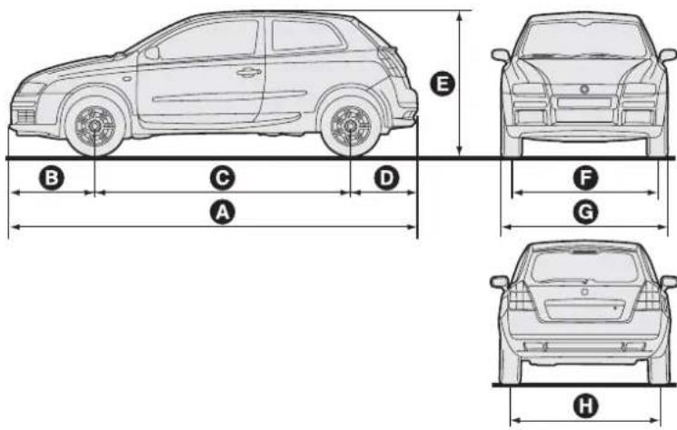
fig. 6
FOC0332m
| Saloon versions3-door | A | B | C | D | E | F | G | |
| 1.416V - 1.616V -1.816V1.9 Multijet | 4182 887 | 2600 695 | 1475 | 1514 (*) | 1784 | 1508 (*) | ||
| 2.420V | 4182 887 | 2600 695 | 1475 | 1518 (*) | 1784 | 1512 (*) |
(*) Track measurements may vary according to rim size.
Dimensions are expressed in mm and refer to the car fitted with standard tyres. The height refers to the car unladen.
Boot volume
Unladen boot volume
(V.D.A. standards) 370 dm ^3 (Δ)
370 dm ^3 (▲)
335 dm ^3 (O)
410 dm ^3 (●)
Extended boot volume (with folded seat back) .....1035 dm ^3 (●)/1120 dm ^3 (△)
(Δ) For versions with rear fixed seat.
(▲) For versions with rear sliding seat (rated value).
(O) For versions with rear sliding seat, set completely in backward position.
(●) For versions with rear sliding seat, set completely in forward position.

fig. 7
F0C0474m
| Saloon versions5-door | A | B | C | D | E | F | G | |
| 1.416V - 1.616V -1.816V1.9 Multijet | 4253 893 | 2600 760 | 1525 | 1514 (*) | 1756 | 1508 (*) | ||
| 2.420V | 4253 893 | 2600 760 | 1525 | 1518 (*) | 1756 | 1512 (*) |
(*) Track measurements may vary according to rim size.
Dimensions are expressed in mm and refer to the car fitted with standard tyres. The height refers to the car unladen.
Boot volume
Unladen boot volume (V.D.A. standards) .... 510 dm ^3 (Δ) 550 dm ^3 (▲)
Extended boot volume (with folded seat back) .... 1380 dm ^3 (○) 1480 dm ^3 (●)
(Δ) For versions with rear fixed seat.
(▲) For versions with rear sliding seat (rated value).
(○) For versions with rear sliding seat, set completely in backward position.
(●) For versions with rear sliding seat, set completely in forward position.
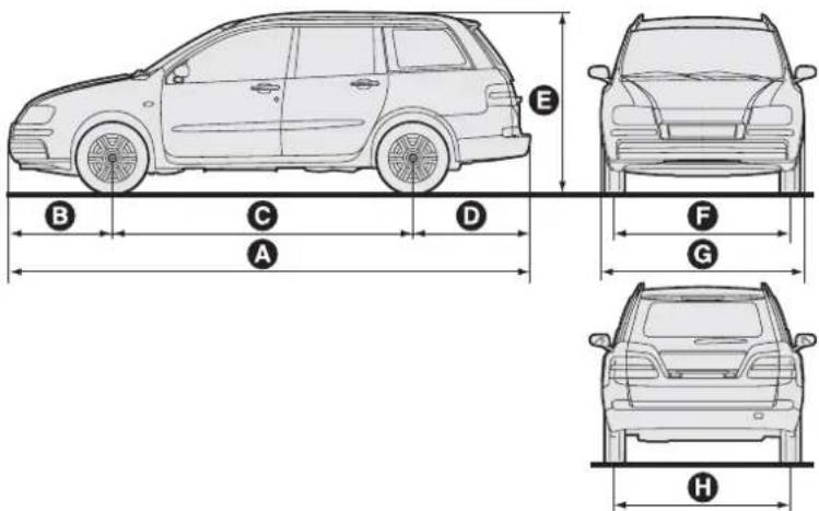
fig. 8
F0C0348m
| Saloon versionsMulti Wagon versions | A | B | C | D | E | F | G | H |
| 1.416v - 1.616v -1.816v 1.9 Multijet | 4516 | 893 | 2600 | 1023 | 1570 | 1514 (*) | 1756/1773 (**) | 1508 |
(*) Track measurements may vary according to rim size. (**) UPROAD versions
PERFORMANCE
Top admitted speed after initial car use in km/h.
SALOON VERSIONS
| 1.416V3-door 5-door 3-door 5-door 3-door 5-door 3-door 5-door 5-door 5-door 5-door 5-door 5-door 5-door 5-door 5-door 5-door 5-door 5-door 5-door 5-door 5-door 5-door 5-door 5-door 5-door 5-door 5-door 5-door 5-door 5-door 5-door 5-door 5-door 5-door 5-door 5-door 5-door 5-door 5-door 5 door 5 door 5 door 5 door 5 door 5 door 5 door 5 door 5 door 5 door 5 door 5 door 5 door 5 door 5 door 5 door 5 door 5 door 5 door 5 door 5 door 5 door 5 door 5 door 5 door 5 door 5 door 5 door 5 door 5 door 5 door 5 door 5 door 5 door | |||||||||||||
| 180 | 178 | 185 | 183 | 202 | 200 | 215 | 213 | 194 | 193 | 192 | 190 | 209 | 207 |
(*) For specific markets
MULTI WAGON VERSIONS
| 1.416v | 1.616v | 1.816v | 1.9 Multijet 8v | 1.9 Multijet 8v (*) | 1.9 Multijet 16v |
| 176 | 183 | 200 | 193 | 190 | 207 |
(*) For specific markets
WEIGHTS
| Weights (kg)(Saloon versions) | 1.416v | 1.616v 1.816v | ||||
| 3-door | 5-door | 3-door | 5-door | 3-door | 5-door | |
| Weight empty(including fluids, 90% fuelin the tank and no optional) | 10901135 (○) | 11451190 (○) | 11501195 (○) | 12051250 (○) | 1240 | 1295 |
| Payload (*) including the driver: | 510 | 510 | 510 | 510 | 510 | 510 |
| Maximum admitted loads (**)- front axle: | 900 | 900 | 950 | 950 | 990 | 990 |
| - rear axle: | 830 | 860 | 830 | 860 | 830 | 860 |
| 1600 | 1655 | 1660 | 1715 | 1750 | 1805 | |
| - total: | 1645 (○) | 1700 (○) | 1705 (○) | 1760 (○) | ||
| Towable loads-trailer with brakes: | 1000/500 (□) | 1000/500 (□) | 1100/500 (□) | 1100/500 (□) | 1200/500 (□) | 1200/500 (□) |
| - trailer without brakes: | 500 | 500 | 500 | 500 | 500 | 500 |
| Maximum load on roof (***) : | 80 | 80 | 80 | 80 | 80 | 80 |
| Maximum load on tow hitch(trailer with brakes): | 60 | 60 | 60 | 60 | 60 | 60 |
(*) If special equipment is fitted (sunroof, tow hitch, etc.) the unladen car weight increases thus reducing the specified payload.
(**) Loads not to be exceeded. The driver is responsible for arranging the loads in the boot an/or on the roof so that they comply with these limits.
(***) Lineaccessori Fiat roof rack, max capacity: 50 kg.
(○) "DYNAMIC" versions.
(□) For specific markets.
| Weights (kg)(Saloon versions) | 2.420v | 1.9 Multijet 8v 1.9 Multijet 16v | ||||
| 3-door | 3-door | 3-door | 3-door | 3-door | 3-door | |
| Weight empty(including fluids, 90% fuelin the tank and no optional) | 1265 | 1320 | 1265 | 1320 | 1285 | 1340 |
| Payload (*) including the driver: | 510 | 510 | 510 | 510 | 510 | 510 |
| Maximum admitted loads (**) | ||||||
| – front axle: | 1030 | 1030 | 1020 | 1020 | 1030 | 1030 |
| – rear axle: | 830 | 830 | 830 | 860 | 830 | 860 |
| – total: | 1775 | 1830 | 1775 | 1830 | 1795 | 1850 |
| Towable loads | ||||||
| – trailer with brakes: | 1300/500 (☐) | 1300/500 (☐) | 1300/500 (☐) | 1300/500 (☐) | 1300/500 (☐) | 1300/500 (☐) |
| – trailer without brakes: | 500 | 500 | 500 | 500 | 500 | 500 |
| Maximum load on roof (***): | 80 | 80 | 80 | 80 | 80 | 80 |
| Maximum load on tow hitch(trailer with brakes): | 60 | 60 | 60 | 60 | 60 | 60 |
(*) If special equipment is fitted (sunroof, tow hitch, etc.) the unladen car weight increases thus reducing the specified payload.
(* *) Loads not to be exceeded. The driver is responsible for arranging the loads in the boot an/or on the roof so that they comply with these limits.
(***) Lineaccessori Fiat roof rack, max capacity: 50 kg.
(□) For specific markets.
| Weights (kg)(Multi Wagon versions) | 1.416v | 1.616v | 1.816v | 1.9 Multijet 8v | 1.9 Multijet 16v |
| Weight empty(including fluids, 90% fuelin the tank and no optional) | 1235 | 1295 | 1385 | 1410 | 1430 |
| Payload (*) including the driver: | 510 | 510 | 510 | 510 | 510 |
| Maximum admitted loads (**) | |||||
| – front axle: | 950 | 950 | 990 | 1020 | 1030 |
| – rear axle: | 960 | 960 | 960 | 960 | 960 |
| – total: | 1745 | 1805 (○) | 1895 | 1920 | 1940 |
| Towable loads | |||||
| – trailer with brakes: | 1000/500 (□) | 1100/500 (□) | 1200/500 (□) | 1300/500 (□) | 1300/500 (□) |
| – trailer without brakes: | 500 | 500 | 500 | 500 | 500 |
| Maximum load on roof (***) | 80 | 80 | 80 | 80 | 80 |
| Maximum load on tow hitch(trailer with brakes): | 60 | 60 | 60 | 60 | 60 |
(*) If special equipment is fitted (sunroof, tow hitch, etc.) the unladen car weight increases thus reducing the specified payload.
(**) Loads not to be exceeded. The driver is responsible for arranging the loads in the boot an/or on the roof so that they comply with these limits.
(***) Lineaccessori Fiat roof rack, max capacity: 50 kg.
(○) "ACTUAL" versions
(□) For specific markets.
CAPACITIES
| 1.416v | 1.616v | 1.816v 2.420v | Recommended products and genuine lubricants | ||||||
| litres | kg | litres | kg | litres | kg | litres | kg | ||
| Fuel tank:including a reserve of: | 589 | - | 589 | - | 589 | - | 589 | - | Unleaded petrolwith no less than 95 R.O.N(Specification EN228) |
| Engine cooling system– with climate control: | - | 5.25 | - | 6.55 | - | 7.3 | - | 8.3 | Mixture of 50% demineralised water and 50%PARAFLU UP |
| Engine sump:Engine sump and filter: | 2.52.8 | 2.22.5 | 4.34.5 | 3.94.0 | 3.74.2 | 3.33.7 | 4.54.7 | 3.94.0 | SELENIA K(versions 1.416v, 1.616v and 1.816v)SELENIA RACING(versions 2.420v) |
| Gearbox/differential casing: | 1.87 | 1.7 | 1.65 | 1.5 | 1.98 | 1.8 | 1.76 | 1.6 | TUTELA CAR TECHNYX |
| Selespeed transmission hydraulic system(where provided): | - | - | - | - | - | - | 0.8 | 0.73 | TUTELA CARCS SPEED |
| Hydraulic brake circuit with ABS: | - | 0.525 | - | 0.525 | - | 0.525 | - | 0.525 | TUTELA TOP 4 |
| Windscreen / rear window / headlight washer fluid reservoir: (*) | 3 (6) | - | 3 (6) | - | 3 (6) | - | 3 (6) | - | Mixture of water and TUTELA PROFESSIONAL SC 35 |
(*) The values in brackets refer to versions with headlight washers.
| 1.9 Multijet 8V | 1.9 Multijet 16V | Recommended products and genuine lubricants | |||
| litres | kg | litres | kg | ||
| Fuel tank:including a reserve of: | 589 | - | 589 | - | Diesel fuel formotor vehicles(Specification EN590) |
| Engine cooling system– with climate control: | - | 7.3 | - | 7.3 | Mixture of 50% demineralised water and 50% PARAFLU UP |
| Engine sump:Engine sump and filter: | 4.44.7 | 3.84.0 | 4.44.7 | 3.84.0 | SELENIA WR |
| Gearbox/differential casing: | 1.76 | 1.6 | 1.87 | 1.7 | TUTELA CAR TECHNYX |
| Hydraulic brake circuitwith ABS: | - | 0.525 | - | 0.525 | TUTELA TOP 4 |
| Windscreen /rear window / headlightwasher fluid reservoir: (*) | 3 (6) | - | 3 (6) | - | Mixture of water and TUTELA PROFESSIONAL SC 35 |
(*) The values in brackets refer to versions with headlight washers.
FLUIDS AND LUBRICANTS
RECOMMENDED PRODUCTS AND THEIR SPECIFICATIONS
| Use Fluid and lubricant specifications Genuine fluids Change for correct car operation and lubricants intervals | |||
| Lubricants for petrol engines | Synthetic-based oil, grade SAE 5W-40, that pass FIAT 9.55535-M2 specification. | SELENIA K (☐) | As per Service Schedule |
| Synthetic-based oil, grade SAE 10W-60 | SELENIA RACING (☐) | As per Service Schedule | |
| Lubricants for diesel engines | Synthetic-based oil, grade SAE 5W-40 that pass FIAT 9.55535-M2 specification | SELENIA WR | As per Service Schedule |
(□) 1.416V, 1.616V and 1.816V versions
(○) 2.420V versions
For regular operation of Multijet versions fitted with DPF, use the genuine lubricant only. In the event of an emergency, lacking the genuine lubricant, top up just once with max. 0.5 l and go to Fiat Dealership as soon as possible.
Should non-genuine SAE 5W-40 products be used, lubricants with minimum ACEA A3 properties for petrol engines and ACEA B4 for Diesel engines are tolerated; in this event top engine performance is not guaranteed.
Using low-quality products, not compliant with ACEA A3 and ACEA B4 properties and specifications could cause engine damages not covered by warranty.
For very cold temperatures, consult Fiat Dealership for the proper Selenia product to use.
| Use Fluid and lubricant specifications Genuine fluids Applications for correct car operation and lubricants | |||
| Lubricants and greases for transmissions | Synthetic-based oil, grade SAE 75W-85 that passes API GL-4 PLUS, FIAT 9.55550 MIL-L-2105 D LEV specifications. | TUTELA CAR TECHNYX | Mechanical gearbox and differential |
| Specific fluid with “ATF DEXRON III” | TUTELA CAR CS SPEED | Selespeed transmission electrically-operated electrohydraulic actuator | |
| Lithium soap based grease. NLGI 0 consistency | TUTELA MRM ZERO | CV joints on differential side (excluding version 1.816v) | |
| Poly-urea oil synthetic-based grease suitable for high temperatures. NLGI 2 consistency | TUTELA STAR 325 | CV joints on differential side submitted to high temperatures (only versions 1.616v) | |
| Molibdenum disulphide, lithium soap based grease. NLGI 2 consistency | TUTELA STAR 500 | CV joint on wheel side (excluding version 1.816v) | |
| Brake fluid | Synthetic fluid, FMVSS n° 116 DOT 4, ISO 4925 SAE J1704, CUNA NC 956-01 | TUTELA TOP 4 | Brake and clutch hydraulic controls |
| Protective agent for radiators | Protective with antifreeze action, red colour based on inhibited monoethylen glycol and organic formula, O.A.T technology, that passes CUNA NC 956-16, ASTM D 3306 specifications. | PARAFLU UP (●) | Cooling circuits. Proportion: 50% down to -35°C. Not to be mixed with other products. |
| Additive for diesel fuel | Additive for diesel fuels with protective action for Diesel engines | DIESEL MIX | To be mixed with diesel fuel (25 cc per 10 litres) |
| Windscreen/ rear window/ headlight washer fluid | Mixture of alcohol and surfactants CUNA NC 956-II | TUTELA PROFESSIONAL SC 35 | To be used diluted or undiluted |
(●) Do not add or mix fluids having different specifications from that already existing.
FUEL CONSUMPTION
The fuel consumption figures given in the table below are determined on the basis of the homologation tests set down by specific European Directives.
The procedures below are followed for measuring consumption:
□ urban cycle: cold starting followed by driving that simulates urban use of the car;
□ extra-urban cycle: frequent accelerating in all gears, simulating extraurban use of the car; the speed varies between 0 and 120 km/h;
☐ combined consumption: is calculated weighing about 37% of urban cycle consumption and about 63% of extraurban consumption.
IMPORTANT The type of route, traffic situations, weather conditions, driving style, general conditions of the car, trim level/equipment/accessories, load, climate control system, roof rack, other situations that affect air drag may lead to different fuel consumption levels than those measured.
Fuel consumption according to Directive 1999/100/EC (litres x 100 km)
Saloon versions
| 1.416v 1.616v 1.816v | |||||
| 3-door 5-door 3-door 5-door 3-door 5-door | |||||
| Urban | 8.2/8.5 (*) 8.5 | 8.8 9.1 11.3 11.5 | |||
| Extra-urban | 5.5/5.6 (*) 5.7 | 5.5 5.8 6.1 6.2 | |||
| Combined | 6.5/6.6 (*) 6.7 | 6.7 7.0 8.0 8.1 | |||
(*) "DYNAMIC" versions
| 2.420v | 1.9 Multijet 8v | 1.9 Multijet 16v | ||||
| 3-door 5-door 3-door | 5-door | 3-door 5-door | ||||
| Urban | 13.5 | 13.6 | 6.7 | 6.8 7.5 7.7 | ||
| Extra-urban | 7.6 | 7.6 4.5 | 4.5 4.5 | 4.7 | ||
| Combined | 9.7 | 9.8 5.3 | 5.4 5.6 | 5.8 | ||
Fuel consumption according to Directive 1999/100/EC (litres x 100 km)
Multi Wagon versions
| 1.416v | 1.616v | 1.816v | 1.9 Multijet 8v | 1.9 Multijet 16v | |
| Urban | 8.7 9.2 11.7 | 7.1 7.7 | |||
| Extra-urban | 5.8 6.0 6.3 | 4.7 4.7 | |||
| Combined | 6.8 7.2 8.3 | 5.6 5.8 |
CO _2 EMISSIONS
The CO_2 , emission levels at the exhaust given in the following table refer to combined consumption.
CO _2 emissions according to 1999/100/EC Directive (g/km)
Saloon versions
| 1.416v 1.616v 1.816v | |||
| 3-door 5-door | 3-door 5-door 3-door 5-door | ||
| 153/158 (*) 160 | 159 165 190 194 | ||
(*) "DYNAMIC" versions
| 2.420V | 1.9 Multijet 8V | 1.9 Multijet 16V | |||
| 3-door 5-door | 3-door 5-door | 3-door | 5-door | ||
| 231 | 233 | 139 | 142 | 148 | 154 |
Multi Wagon versions
| 1.416v | 1.616v | 1.816v | 1.9 Multijet 8v | 1.9 Multijet 16v |
| 162 | 170 | 197 | 148 | 154 |
INDEX
ABS 95
Accessories purchased
by the owner .... 101
Air bags
-front....126
- side.... 130
Air filter 225
Armrests (front rear).... 70
Ashtray....72
ASR 98
At the filling station.... 105
Automatic headlights sensor (daylight sensor)......
Battery
– checking the charge.... 226
-jump starting.... 170
-replacing 227
Bodywork.... 233
Bonnet....92
Boot 81
Boot light (bulb replacement) ..... 195
Brake Assist 96
Brakes.... 244
Bulb (replacement).... 181
- types of bulbs .... 182
Capacities.... 257
Car inactivity.... 156
Car maintenance.... 209
- additional checks 213
– annual Inspection Schedule...... 213
– scheduled service ...... 210
- Service Schedule.... 211
Cargo box 91
Carrying children safely 116
Ceiling lights 67
Central door locking system ..... 79
Checking fluid levels 216
Child lock 79
Child restraint systems (specifications for use) ....119
Cigar lighter 72
Climate control system
- automatic two-zone climate control system .... 51
– manual climate control system .. 48
CO_2 emissions 263
Code Card 10
Containing running costs .... 149
Controls 68
Correct use of the car 135
Courtesy mirror light (bulb replacement) 194
Cruise Control 65
Current outlet....72
Cut-off switch fuel 69
Dashboard.... 5
Dashboard and controls .... 4
Daylight sensor 61
Dead lock (device) 14
Diesel fuel filter 225
Diesel particulate filter (DPF) ..... 108
Dimensions 250
Dipped beam headlights.... 59
Direction indicators
-control 60
- front bulb replacement .... 186
- rear bulb replacement .... 188
– side bulb replacement .... 186
Doors 79
Dualdrive (electric power steering) 102
Easy entry 38
Electric power steering "Dualdrive".. 102
Electronic alarm 17
Engine
- identification code 240
- technical data.... 241-242
Engine compartment
-washing 234
Engine oil
– consumption 220
Environment protection 108
EOBD (system) 99
ESP (system) 97
External lights 59
Fiat CODE (system) 8
Fire extinguisher 208
Fix&Go automatic 177
Flashing the headlights 59
Fluid level checks 216
Fluids and lubricants 259
Follow me home (device) 60
Front fog lights 68-69
- (bulb replacement).... 186
Fuel consumption 261
Fuel feed/ignition 241
Fuel filler cap 106
Fuses (replacement) 196
Gearbox
- using manual gearbox .... 140
- using Selespeed gearbox .... 141
Glass holder 73
Glove box light
(bulb replacement) 194
Glove box/oddment
compartments 71
Handbrake 139
Hazard lights 68
Head restraints 41
Headlight washer.... 65
Headlights.... 94
Heating and ventilation system .. 44-46
Identification data 238
If an exterior light burns out 184
If an interior light burns out ...... 192
Ignition switch 20
In an emergency 169
Independent additional heater ..... 56
Installation of electric/
electronic devices.... 101
Instrument panel 6
Instruments 21
Interior fittings 70
Interiors 235
Isofix (child restraint system) ..... 121
Jacking the car 206
Keys 10
Load limiters 113
Main beam headlights.... 59
MSR (system) 99
Multifunction display 23
Number plate lights
(bulb replacement) 191
OCS
(Occupant Classification System) .. 129
Oddment compartments 73
Paint 233
Parking 139
Parking lights 69
Parking sensors 103
Performance 253
Pollen filter 225
Power windows 80
Presetting for mounting the
"Isofix" child restraint system ..... 121
Presetting for mounting the “Universal Isofix” child restraint system .... 124
Pretensioners 113
Protecting the environment ..... 108
Puddle light/door opening light (bulb replacement) 195
Radio transmitters and cellular telephones.... 101
Rain sensor 63
Rear fog lights.... 69
Rear window washer/wiper...... 64
Rear window wiper - blades .... 231 - control .... 64 - nozzles .... 232
Rearview mirrors 43
Reversing lights (bulb replacement) 188-189
Rims – understanding rim marking...... 246
Roof rack/ski rack 93
Rubber hoses 230
Safety devices 109
S.B.R. system 112
Seat belts 110
Seats 37
- cleaning 235
- easy entry.... 38
- manually adjustable front seats .. 37
- rear sliding seats 39
- seat warming 38
Selespeed (gearbox) 141
Side/taillights 59
Ski tunnel 91
Skywindow (blade sunroof) 74
Smart washing 63
Snow chains 155
Sound system (presetting).... 100
Spark plugs 241
Starting the engine 136
Steering 244
Steering column lock 20
Steering wheel.... 42
Sun visors 73
Sunroof (Skywindow) 74
Suspensions 244
Symbols 8
Technical specifications ..... 237
Third brake light (bulb replacement) 191
Tilting shelf 72
Top speeds 253
Towing the car.... 206
Towing trailers.... 151
Transmission 241
Trip Computer.... 34
Tyre repair kit (Fix&Go automatic).... 177
Tyres
- changing 171
- pressure.... 246
– snow tyres ...... 154
-standard tyres 247
- understanding tyre marking...... 246
Using the manual gearbox .... 140
Using the Selespeed gearbox ..... 141
Warning lights and messages .. 157
Weights.... 254
Wheel
- changing 171
Wheel geometry.... 245
Window (washing/cleaning)...... 62-234
Windscreen washer/wiper...... 62
Windscreen wiper
- blades 231
-control 62
- nozzles 232
INSTRUMENT PANEL
(right-hand drive versions)


1.416V - 1.616V - 1.816V versions
A Rev. counter
B Fuel level gauge with reserve warning light
C Engine coolant temperature gauge and excessive temperature warning light
D Speedometer (speed indicator)
E Multifunction display.
For markets where provided, the speedometer (speed indicator) can have the graduated scale in km/h instead of MPH.
1.9 Multijet versions
A Rev. counter
B Fuel level gauge with reserve warning light
C Engine coolant temperature gauge and excessive temperature warning light
D Speedometer (speed indicator)
E Multifunction display.
For markets where provided, the speedometer (speed indicator) can have the graduated scale in km/h instead of MPH.
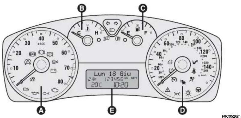
2.420v Selespeed ABARTH versions
A Rev. counter
B Fuel level gauge with reserve warning light
C Engine coolant temperature gauge and excessive temperature warning light
D Speedometer
E Multifunction display
For markets where provided, the speedometer (speed indicator) can have the graduated scale in km/h instead of MPH.
PROVISIONS FOR THE PROCESSING OF A VEHICLE AT THE END OF ITS LIFE-CYCLE
For years now Fiat has been developing its global commitment towards the safeguarding and protection of the Environment through the continuous improvement of its production processes and the making of increasingly more “eco friendly” products. With a view to guaranteeing the best possible service to clients in full observance of environmental standards and in response to the obligations imposed by European Directive 2000/53/EC on end-of-life vehicles, Fiat offers its clients the possibility to hand in their vehicle* at the end of its life span without additional costs.
The European Directive, in fact, provides for the take-back of the vehicle without the last holder or owner of the same incurring expenses due to the fact that the market value of the vehicle is zero or negative. In particular, in almost all of the countries of the European Union, up until 1st January 2007, take-back of the vehicle free of charge only applies to vehicles registered from 1 July 2002 on, while, from 2007 on, take-back will be carried out free of charge, independently of the year of registration, provided that the vehicle still contains all its essential component parts (especially engine and body) and is free from additional waste materials.
Our contracted network of authorised treatment facilities has been carefully selected in order to provide a quality service to our customers by de-polluting and recycling “End of Life Vehicles” to approved environmental standards. To find out the location of your nearest authorised treatment facility, offering free of charge take-back, simply contact one of our dealers or refer to the Fiat web site or call the toll free number 00800 3428 0000.
* Passenger transportation vehicles to seat a max. of nine persons, having a total admissible weight of 3.5 t
SELÈNIA®
At the heart of your engine.

Always ask your mechanic for
SELÉNIA®
Oil change? The experts recommend Selenia.
The engine of your car is factory filled with Selenia. This is an engine oil range which satisfies the most advanced international specifications. Its superior technical characteristics allow Selenia to guarantee the highest performance and protection of your engine.
The Selenia range includes a number of technologically advanced products:
SELENIA PERFORMER MULTIPOWER
Particularly ideal for the protection of new generation petrol engines, very effective even in the most severe weather conditions. It guarantees a reduction in fuel consumption (Energy conserving) and it is also ideal for alternative engines.
SELENIA K
is the synthetic lubricant with innovative technology, which ensures improved cold starting for petrol engines and the utmost protection also under typically “urban” conditions of use. Owing to its 5W-40 viscosimetric grade and its special formulation it more effectively meets the emission limits required by new European regulations and exceeds the major international specifications.
SELENIA WR
Oil specifically designed for common rail Multijet engines. Particularly effective during cold starts, it guarantees maximum wear protection and hydraulic tappets control, reduction in consumption and stability at high temperatures.
SELENIA DIGITECH
Fully synthetic lubricant for petrol and diesel engines. Its advanced technology guarantees maximum protection, a reduction in consumption and reliability in extreme climate conditions.
The range also includes Selenia StAR, Selenia Racing, Selenia 20K Alfa Romeo, Selenia TD, Selenia Performer 5W-40 For further information on Selenia products visit the web site www.flselenia.com.
VERSIONS STANDARD TYRES SPARE
| Size Medium load Full load WHEEL | ||||||
| Front Rear Front Rear | ||||||
| 1.416v | 195/65 R15 91T | 1.9 | 1.9 | 2.1 - 2.3 (☐)/3.0 (**) | 2.1 - 2.3 (☐)/3.0 (**) | 4.2 |
| 205/55 R16 91V | 2.1 | 2.1 | 2.3 | 2.3 | ||
| 195/65 R15 91H (☐) | 1.9 | 1.9 | 2.1 - 2.3 (☐)/3.0 (**) | 2.1 - 2.3 (☐)/3.0 (**) | ||
| 215/45 R17 87W | 2.3 | 2.3 | 2.7 | 2.5 | ||
| 1.9 Multijet 8v1.616v | 195/65 R15 91H | 1.9 | 1.9 | 2.1 - 2.3 (☐)/3.0 (**) | 2.1 - 2.3 (☐)/3.0 (**) | 4.2 |
| 205/55 R16 91V | 2.1 | 2.1 | 2.3 | 2.3 | ||
| 215/45 R17 87W | 2.3 | 2.3 | 2.7 | 2.5 | ||
| 1.816v1.9 Multijet 16v | 195/65 R15 91V | 1.9 | 1.9 | 2.1 - 2.3 (☐)/3.0 (**) | 2.1 - 2.3 (☐)/3.0 (**) | 4.2 |
| 205/55 R16 91V | 2.1 | 2.1 | 2.3 | 2.3 | ||
| 215/45 R17 87W | 2,3 | 2.3 | 2.7 | 2.5 | ||
| 2.420v | 205/55 R16 91W | 2.1 | 2.1 | 2.3 | 2.3 | 4.2 |
| 215/45 R17 87W | 2.3 | 2.3 | 2.7 | 2.5 | ||
(7) Multi Wagon Versions
(**) Under maximum load conditions = 510 kg (comprising driver's weight. special equipment and the remaining load distributed over the rear pulled down seats).
ENGINE OIL CHANGE
| 1.416v | 1.616v | 1.816v | 2.420v | 1.9 Multijet 8v1.9 Multijet 16V | ||||||
| litres | kg | litres | kg | litres | kg | litres | kg | litres | kg | |
| Engine sump | 2.5 | 2.2 | 4.3 | 3.9 | 3.7 | 3.3 | 4.5 | 3.9 | 4.4 | 3.8 |
| Engine sump and filter | 2.8 | 2.5 | 4.9 | 4.4 | 4.2 | 3.7 | 4.7 | 4.0 | 4.7 | 4.0 |
REFUELLING (litres)
| 1.416v - 1.616v - 1.816v - 2.420v - 1.9 Multijet 8v - 1.9 Multijet 16v | |
| Tank capacity 58 | |
| Reserve 9 |
Only refuel cars with petrol engines with unleaded petrol with octane rating (RON) not less than 95.
Only refuel cars with diesel engines with diesel fuel for motor vehicles conforming to the EN590 European Specification.
Fiat Auto S.p.A.
The data contained in this publication is intended merely as a guide. FIAT reserves the right to modify the models and versions described in this booklet at any time for technical and commercial reasons. If you have any further questions please consult your FIAT dealer. Printed in recycled paper without chlorine.

- FIAT STILO
- OWNER HANDBOOK
- Dear Customer,
- MUST BE READ!
- REFUELLING
- ENGINE STARTING
- PARKING ON FLAMMABLE MATERIAL
- RESPECTING THE ENVIRONMENT
- ELECTRICAL ACCESSORIES
- CODE card
- SCHEDULED SERVICING
- THE OWNER HANDBOOK CONTAINS...
- DASHBOARD AND CONTROLS
- DASHBOARD
- 1.416V - 1.616V - 1.816V versions
- Multijet versions
- 2.420v Selespeed Abarth versions
- SYMBOLS
- THE FIAT CODE SYSTEM
- OPERATION
- Warning light coming on when driving
- THE KEYS
- KEY WITHOUT REMOTE CONTROL (where provided)
- KEY WITH REMOTE CONTROL
- WARNING
- Opening the doors and the tailgate
- Locking the doors and the tailgate
- Opening the tailgate by the remote control
- Opening the rear heated window lid (MultiWagon versions)
- Leds on the driver's door
- Request for additional remote controls
- Replacing the battery of the key with remote control
- DEAD LOCK DEVICE (where provided)
- Device activation
- Device deactivation
- ALARM (where provided)
- WHEN THE ALARM IS TRIGGERED
- HOW TO ACTIVATE THE ALARM
- HOW TO DEACTIVATE THE ALARM
- VOLUMETRIC PROTECTION SENSORS
- Volumetric protection deactivation
- ANTI-RAISING SENSOR
- Anti-raising protection deactivation
- INDICATIONS OF ATTEMPTS TO BREAK IN
- HOW TO CUT OFF THE ALARM SYSTEM
- IGNITION SWITCH
- STEERING COLUMN LOCK
- Engaging
- Disengaging
- INSTRUMENTS
- ENGINE COOLANT TEMPERATURE GAUGE
- FUEL LEVEL GAUGE
- MULTIFUNCTION DISPLAY
- INFORMATION ON "STANDARD" SCREEN fig. 20
- CONTROL BUTTONS fig. 21
- SETUP MENU fig. 22
- Speed limit (Speed Beep)
- Automatic headlight sensor sensitivity adjustment (Headl. sensor) (where provided)
- Trip B On/Off (TripB data)
- Setting the clock (Set time)
- Setting the date (Set date)
- Audio info repetition (See radio)
- Door opening mode (Key)
- Automatic central door locking when travelling (Autoclose)
- Setting units (Units)
- Selecting the language (Language)
- Setting the buzzer volume (Buzzer volume)
- Adjusting the button volume (Button vol.)
- S.B.R. buzzer reactivation (Belt buzzer)
- Scheduled Servicing (Service)
- Exit Menu
- Instrument panel, display and button lighting adjustment (Light rheostat)
- TRIP COMPUTER
- GENERAL
- Values displayed
- Range
- Trip distance
- Average consumption
- Instant consumption
- Average speed
- Trip time
- TRIP button fig. 24
- New mission
- Start of journey procedure
- SEATS
- REAR SLIDING SEATS (where provided)
- Back rest angle adjustment
- Moving the seat backwards or forwards
- HEAD RESTRAINTS
- FRONT
- REAR
- STEERING WHEEL
- REARVIEW MIRRORS
- DRIVING MIRROR
- DOOR MIRRORS
- Manual adjustment
- Electrical adjustment
- HEATING/CLIMATE CONTROL SYSTEM
- SIDE SWIVEL OUTLETS AND VENTS fig. 41
- CENTRAL VENTS fig. 42
- REAR VENT fig. 43 (where provided)
- HEATING AND VENTILATION
- CONTROLS
- WARMING THE PASSENGER COMPARTMENT
- FRONT WINDOW FAST DEMISTING/DEFROSTING
- Window demisting
- HEATED REAR WINDOW AND DOOR MIRROR DEMISTING/DEFROSTING
- FAN SPEED ADJUSTMENT
- RECIRCULATION
- MANUAL CLIMATE CONTROL SYSTEM (where provided)
- AIR RECIRCULATION
- CLIMATE CONTROL (cooling)
- Cooling adjustment
- LOOKING AFTER THE SYSTEM
- AUTOMATIC TWO-ZONE CLIMATE CONTROL SYSTEM (where provided)
- Description
- SWITCHING THE CLIMATE CONTROL SYSTEM ON
- HOW TO USE THE AUTOMATIC FUNCTION (AUTO)
- FAST FRONT WINDOW DEMISTING/DEFROSTING (MAX-DEF function)
- INSIDE AIR RECIRCULATION ON/OFF AND AQS FUNCTION (Air Quality System)
- AQS (Air Quality System) function activation
- ALIGNMENT OF SET TEMPERATURES (MONO function)
- CLIMATE CONTROL COMPRESSOR ON/OFF
- Compressor on
- Compressor off
- AIR DISTRIBUTION SELECTION
- SWITCHING THE CLIMATE CONTROL SYSTEM OFF
- EXTERNAL LIGHTS
- LIGHTS SWITCHED OFF fig. 47
- SIDELIGHTS fig. 47
- DIPPED BEAM HEADLIGHTS fig. 47
- MAIN BEAM HEADLIGHTS fig. 47
- FLASHING THE HEADLIGHTS fig. 47
- DIRECTION INDICATORS fig. 48
- "FOLLOW ME HOME" DEVICE fig. 49
- Activation
- Deactivation
- AUTOMATIC HEADLIGHTS SENSOR (daylight sensor) fig. 50 (where provided)
- WINDOW WASHING
- WINDSCREEN WASHER/WIPER fig. 51
- "Smart washing" function fig. 52
- RAIN SENSOR (where provided)
- REAR WINDOW WASHER/ WIPER fig. 54
- HEADLIGHT WASHER fig. 55
- CRUISE CONTROL (constant speed regulator) (where provided)
- DEVICE ENGAGEMENT
- TO MEMORISE SPEED
- TO RESET THE MEMORISED SPEED
- TO INCREASE THE MEMORISED SPEED
- TO REDUCE MEMORISED SPEED
- DEVICE DISENGAGEMENT
- CEILING LIGHTS
- FRONT CEILING LIGHT fig. 57
- Courtesy lights
- Central light
- REAR CEILING LIGHT
- (where provided) fig. 58
- Versions without sunroof
- Versions with sunroof fig. 59
- HAZARD LIGHTS fig. 60
- FRONT FOG LIGHTS (where provided)
- PARKING LIGHTS
- REAR FOG LIGHTS
- FUEL CUT-OFF SWITCH fig. 62
- INTERIOR FITTINGS
- FRONT ARMREST (where provided)
- REAR ARMREST (where provided)
- Lower oddment compartment on passenger's side
- Oddment compartments under the seats (where provided) fig. 69
- CURRENT OUTLET (12V)
- CIGAR LIGHTER (where provided)
- ASHTRAY (where provided)
- TILTING SHELF (where provided)
- Resetting the shelf (after releasing)
- GLASS HOLDER
- ODDMENT COMPARTMENT
- fig. 75
- SUN VISORS fig. 76
- "SKYWINDOW" (BLADE SUNROOF) (where provided)
- SUNROOF OPENING
- GLASS BLADES OPENING (knob turning clockwise)
- With closed blades and sun curtain open
- SUNROOF CLOSING
- Glass blades closing (knob turning counterclockwise) fig. 80
- SUN CURTAIN OPENING/CLOSING
- SUNROOF OPENING/CLOSING
- With key without remote control (where provided)
- With key with remote control
- INITIALISATION PROCEDURE
- EMERGENCY OPERATION
- DOORS
- CENTRAL DOOR LOCKING SYSTEM
- From the outside
- From the inside
- CHILD LOCK (5-door versions)
- POWER WINDOWS
- Driver side fig. 87
- BOOT
- OPENING FROM THE OUTSIDE
- With key without remote control (where provided) fig. 90
- TAILGATE EMERGENCY OPENING FROM PASSENGER COMPARTMENT (Multi Wagon versions only)
- HEATED REAR WINDOW FLAP OPENING (where provided) (Multi Wagon versions)
- TAILGATE CLOSING
- EXTENDING THE BOOT
- Partial extension (1/3 or 2/3) fig. 94-95
- Versions with fixed rear seat
- To extend the boot totally
- Removing the boot cover
- BOOT COVER
- (Multi Wagon versions)
- TO RETURN THE REAR SEAT BACK TO ITS ORIGINAL POSITION
- Versions with rear fixed seat
- Versions with rear sliding seat (where provided)
- ANCHORING THE LOAD
- BONNET
- TO OPEN THE BONNET
- TO CLOSE THE BONNET
- ROOF RACK/ SKI RACK
- Multi Wagon versions
- HEADLIGHTS
- ADJUSTING THE HEADLIGHT BEAM
- HEADLIGHT AIMING DEVICE
- To adjust the headlight slant
- Correct positions as a function of the load
- FRONT FOG LIGHT ADJUSTMENT
- HEADLIGHT BEAM ADJUSTMENT ABROAD
- ABS SYSTEM
- ABS SYSTEM INTERVENTION
- FAILURE INDICATIONS
- ABS failure
- EBD failure
- BRAKE ASSIST
- (emergency braking assistance) (where provided)
- ESP SYSTEM (Electronic Stability Program) (where provided)
- ESP SYSTEM INITIALISATION (after disconnecting the battery)
- ASR SYSTEM
- (Antislip Regulation)
- Switching on/off of the ASR system
- MSR system
- (engine braking torque control)
- EOBD SYSTEM
- SOUND SYSTEM (where provided)
- ACCESSORIES PURCHASED BY THE OWNER
- INSTALLATION OF ELECTRIC/ELECTRONIC DEVICES
- RADIO TRANSMITTERS AND CELLULAR TELEPHONES
- "DUALDRIVE" ELECTRIC POWER STEERING SYSTEM
- ACTIVATION/DEACTIVATION (CITY function)
- PARKING SENSORS (where provided)
- BUZZER WARNINGS
- Detection distances
- GENERAL WARNINGS
- AT THE FILLING STATION
- PETROL ENGINES
- DIESEL ENGINES
- FUEL FILLER CAP fig. 128
- Saloon versions
- PROTECTING THE ENVIRONMENT
- DIESEL PARTICULATE FILTER (DPF) (where provided)
- Diesel Particulate Filter clogged
- SAFETY DEVICES
- SEAT BELTS
- USING THE SEAT BELTS
- S.B.R. SYSTEM
- FRONT SEAT BELT HEIGHT ADJUSTMENT
- PRETENSIONERS
- LOAD LIMITERS
- GENERAL INSTRUCTIONS FOR USING THE SEAT BELTS
- HOW TO KEEP THE SEAT BELTS ALWAYS IN EFFICIENT CONDITIONS
- CARRYING CHILDREN SAFELY
- GROUP 0 and 0+
- GROUP I
- GROUP 2
- GROUP 3
- PASSENGER SEAT COMPLIANCE WITH REGULATIONS ON CHILD'S SEAT USE
- Key:
- Below is a summary of the rules of safety to be followed for carrying children:
- PRESETTING FOR MOUNTING THE "ISOFIX TYPE" CHILD RESTRAINT SYSTEM
- FITTING THE ISOFIX TYPE SEAT
- Groups 0 and 0+
- PRESETTING FOR MOUNTING THE "UNIVERSAL ISOFIX" CHILD RESTRAINT SYSTEM
- PASSENGER SEAT COMPLIANCE WITH REGULATIONS ON UNIVERSAL ISOFIX CHILD'S SEAT USE
- Key
- FRONT AIR BAGS
- "SMART BAG" SYSTEM (FRONT MULTISTAGE AIR BAGS)
- fig. 22
- MANUAL DEACTIVATION OF PASSENGER'S FRONT AIR BAG
- FRONT PASSENGER CLASSIFICATION SENSOR (OCS = Occupant Classification System) (where provided)
- SIDE AIR BAGS (Side bag - Window bag)
- SIDE BAG (where provided)
- WINDOW BAG (where provided) fig. 26
- MANUAL DEACTIVATION OF REAR SIDE BAGS
- (where provided)
- CORRECT USE OF THE CAR
- STARTING PROCEDURE FOR PETROL VERSIONS
- STARTING PROCEDURE FOR DIESEL VERSIONS
- HOW TO WARM UP THE ENGINE AFTER IT HAS JUST STARTED (petrol and diesel engines)
- EMERGENCY START-UP
- STOPPING THE ENGINE
- PARKING THE CAR
- HANDBRAKE
- USING THE MANUAL GEARBOX
- USING THE "SELESPEED" GEARBOX (where provided)
- Manual mode (MANUAL)
- Automatic mode (AUTO)
- SYSTEM ACTIVATION
- MOVING-OFF
- IMPORTANT NOTES
- GEARSHIFTING
- Through lever
- Through steering wheel controls
- SWITCHING OFF THE ENGINE AND SYSTEM DEACTIVATION
- STOPPING THE CAR
- TOWING THE CAR
- CONTAINING RUNNING COSTS
- GENERAL CONSIDERATIONS
- Car maintenance
- Tyres
- Unnecessary loads
- Roof rack/ski rack
- Electric devices
- Climate control
- Spoilers
- DRIVING STYLE
- Starting
- Unnecessary actions
- Gear selection
- Top speed
- Acceleration
- CONDITIONS OF USE
- Cold starting
- Traffic situations and road conditions
- Traffic hold-ups
- TOWING TRAILERS
- INSTALLING THE TOW HOOK
- Assembly diagram fig. 13-14
- SNOW TYRES
- SNOW CHAINS
- CAR INACTIVITY
- WARNING LIGHTS AND MESSAGES
- Low brake fluid level
- Handbrake on
- BRAKE PAD WEAR (red)
- AIR BAG FAILURE (red)
- FRONT PASSENGER'S AIR BAG
- DEACTIVATED
- REAR SIDE BAGS DEACTIVATED (where provided) (amber)
- SEAT BELTS NOT FASTENED (red)
- LOW BATTERY CHARGE (red)
- LOW ENGINE OIL PRESSURE (red)
- Low engine oil pressure
- Exhaust oil
- (Multijet versions with DPF)
- SELESPEED TRANSMISSION FAILURE (red)
- "DUALDRIVE" ELECTRIC POWER STEERING FAILURE (red)
- HIGH TEMPERATURE ENGINE COOLANT FLUID (red)
- INCOMPLETE DOOR LOCKING (red)
- GENERIC FAILURE INDICATION (amber)
- Inertial fuel cut-off switch intervened
- Sensor failure
- DIESEL PARTICULATE FILTER CLOGGED (amber) (Multijet versions)
- ENGINE CONTROL SYSTEM FAILURE (EOBD) (amber)
- ESP SYSTEM (amber)
- GLOW PLUG WARMING FAILURE (Multijet versions) (amber)
- Glow plug warming
- Glow plug warming failure
- WATER IN DIESEL FUEL FILTER
- INEFFICIENT ABS SYSTEM (amber)
- INEFFICIENT EBD (ELECTRONIC BRAKING
- DISTRIBUTOR) (red) (amber)
- CAR PROTECTION SYSTEM FAILURE-FIAT CODE (amber)
- ALARM FAILURE (where provided) (amber) BREAK-IN ATTEMPT (amber)
- Car protection system failure
- Alarm failure (where provided)
- Break-in attempt
- EXTERNAL LIGHT FAILURE (amber)
- REAR FOG LIGHTS (amber)
- FRONT FOG LIGHTS (green)
- LEFT-HAND DIRECTION INDICATOR (green - intermittent)
- RIGHT-HAND DIRECTION INDICATOR (green - intermittent)
- SIDELIGHTS AND LOW BEAMS (green) FOLLOW ME HOME
- Side/taillights and low beams
- Follow me home
- MAIN BEAMS (blue)
- CRUISE CONTROL (where provided) (green)
- POSSIBLE PRESENCE OF ICE ON THE ROAD
- LIMITED RANGE
- SPEED LIMIT EXCEEDED
- IN AN EMERGENCY
- JUMP STARTING
- BUMP STARTING
- IF A TYRE IS PUNCTURED
- GENERAL INSTRUCTIONS
- REFITTING THE STANDARD WHEEL
- Versions with steel rims
- Versions with alloy rims
- When you have finished
- QUICK TYRE REPAIR KIT FIX & GO automatic
- IT SHOULD BE NOTICED THAT:
- INFLATING PROCEDURE
- FOR CHECKING AND RESTORING PRESSURE ONLY
- CYLINDER REPLACEMENT PROCEDURE
- WHEN NEEDING TO CHANGE A BULB
- TYPES OF BULBS fig. 19
- IF AN EXTERIOR LIGHT BURNS OUT
- FRONT LIGHT UNITS
- fig. 20-21
- Gas-filled filament lamps
- MAIN BEAM HEADLIGHTS fig. 23
- DIRECTION INDICATORS
- Front fig. 24
- Side fig. 25
- FRONT FOG LIGHTS (where provided) fig. 26
- FRONT SIDELIGHTS
- REAR LIGHT UNITS (saloon versions)
- 3-door versions
- 5-door versions
- REAR LIGHT UNITS
- Tailgate light unit
- Side fixed light unit
- ADDITIONAL BRAKING LIGHT (THIRD STOP)
- NUMBER PLATE LIGHTS
- Saloon versions fig. 39
- Multi Wagon versions fig. 40
- IF AN INTERIOR LIGHT BURNS OUT
- FRONT CEILING LIGHT
- Versions without Skywindow sunroof
- Versions with Skywindow sunroof
- REAR CEILING LIGHT (where provided)
- COURTESY MIRROR LIGHT (where provided)
- GLOVEBOX LIGHT fig. 51
- BOOT LIGHT
- PUDDLE / DOOR LIGHTS fig. 54
- IF A FUSE BLOWS
- FUSE LOCATION
- Fuse box on the dashboard fig. 57
- Fuse box next to the battery fig. 59
- Fuse box on the battery positive pole fig. 61
- Fuse box in the boot fig. 65
- IF THE BATTERY IS FLAT
- JACKING THE CAR
- TOW RING HOOKING
- TOWING SELESPEED VERSIONS
- FIRE EXTINGUISHER (where provided)
- CARRAMUTENANCE
- ANNUAL INSPECTION SCHEDULE
- ADDITIONAL CHECKS
- IMPORTANT - Engine oil (petrol and Multijet versions without DPF)
- IMPORTANT - Engine oil (Multijet versions with DPF)
- IMPORTANT - Air cleaner
- IMPORTANT - Pollen filter
- IMPORTANT - Diesel filter
- IMPORTANT - Battery
- CHECKING FLUID LEVELS
- ENGINE OIL fig. 7-8-9-10-11-12
- Checking engine oil
- Topping up engine oil
- Engine oil consumption
- HYDRAULIC SYSTEM OIL FOR ACTUATING SELESPEED GEARBOX (where provided)
- ENGINE COOLANT FLUID
- fig. 14-15-16
- WINDSCREEN/REAR WINDOW/HEADLIGHT WASHER FLUID fig. 17-18
- BRAKE FLUID fig. 19
- AIR FILTER
- POLLEN FILTER
- DIESEL FUEL FILTER
- DRAINING THE CONDENSE (Multijet versions)
- BATTERY
- CHECKING THE CHARGE fig. 20
- CHANGING THE BATTERY
- USEFUL ADVICE
- FOR LENGTHENING THE LIFE OF YOUR BATTERY
- WHEELS AND TYRES
- RUBBER HOSES
- WINDSCREEN/ REAR WINDOW WIPERS
- BLADES
- Changing the windscreen wiper blades
- Changing the rear window blade
- SPRAY NOZZLES
- Windscreen wiper fig. 25
- Rear window wiper fig. 26-27
- BODYWORK
- PROTECTION FROM ATMOSPHERIC AGENTS
- BODY AND UNDERBODY WARRANTY
- ADVICE FOR PRESERVING THE BODYWORK
- Paint
- Front headlights
- Windows
- Engine compartment
- INTERIORS
- CLEANING SEATS AND FABRIC AND VELVET PARTS
- CLEANING LEATHER SEATS
- INTERIOR PLASTIC PARTS
- STEERING WHEEL/GEAR LEVER KNOB WITH GENUINE LEATHER COVERING
- TECHNICAL SPECIFICATIONS
- IDENTIFICATION DATA
- MODEL PLATE fig. 2
- ENGINE MARKING
- BODYWORK PAINT IDENTIFICATION PLATE fig. 4
- CHASSIS MARKING fig. 3
- WHEELS
- RIMS AND TYRES
- SPARE WHEEL
- WHEEL GEOMETRY
- UNDERSTANDING TYRE MARKING fig. 5
- COLD TYRE INFLATION PRESSURE (bar)
- DIMENSIONS
- Boot volume
- PERFORMANCE
- FLUIDS AND LUBRICANTS
- FUEL CONSUMPTION
- Fuel consumption according to Directive 1999/100/EC (litres x 100 km)
- CO _2 EMISSIONS
- INDEX
- PROVISIONS FOR THE PROCESSING OF A VEHICLE AT THE END OF ITS LIFE-CYCLE
- SELÈNIA®
- At the heart of your engine.
- Oil change? The experts recommend Selenia.
- SELENIA PERFORMER MULTIPOWER
- SELENIA K
- SELENIA WR
- SELENIA DIGITECH
Brand : FIAT
Model : Stilo (2012)
Category : Automobile