
WT-2000ARM - Router AIRLIVE - Free user manual and instructions
Find the device manual for free WT-2000ARM AIRLIVE in PDF.


| Product Type | Wireless Router |
| Brand | AirLive |
| Model | WT-2000ARM |
| Dimensions (Approx.) | 200 x 150 x 30 mm |
| Weight (Approx.) | 0.5 kg |
| Power Supply | 12V DC, 1A |
| Wireless Standards | 802.11b/g/n |
| Frequency Band | 2.4 GHz |
| Maximum Wireless Speed | 300 Mbps |
| Ethernet Ports | 4 x LAN 10/100 Mbps, 1 x WAN 10/100 Mbps |
| Antenna Type | 2 x External detachable antennas |
| Security Features | WEP, WPA, WPA2, MAC filter, SPI firewall |
| VPN Support | PPTP, L2TP, IPSec pass-through |
| Management Interface | Web-based GUI (HTTP/HTTPS) |
| Default IP Address | 192.168.1.1 |
| Default Login | admin / admin |
| Reset Button | Yes, pinhole reset |
| Operating Temperature | 0°C to 40°C |
| Storage Temperature | -20°C to 70°C |
| Humidity (Operating) | 10% to 85% non-condensing |
| Certifications | CE, FCC |
| Warranty | 1 year limited |
Frequently Asked Questions - WT-2000ARM AIRLIVE
User questions about WT-2000ARM AIRLIVE
0 question about this device. Answer the ones you know or ask your own.
Ask a new question about this device
Download the instructions for your Router in PDF format for free! Find your manual WT-2000ARM - AIRLIVE and take your electronic device back in hand. On this page are published all the documents necessary for the use of your device. WT-2000ARM by AIRLIVE.
USER MANUAL WT-2000ARM AIRLIVE
Wireless ADSL 2/2+ Modem Router
User's Guide
natural_image
Collection of network equipment including a OrisLink switch, USB drive, network switch, and various electronic devices (no visible text or labels)Copyright
The contents of this publication may not be reproduced in any part or as a whole, stored, transcribed in an information retrieval system, translated into any language, or transmitted in any form or by any means, mechanical, magnetic, electronic, optical, photocopying, manual, or otherwise, without the prior written permission.
FCC Interference Statement
This equipment has been tested and found to comply with the limits for a Class B digital device pursuant to Part 15 of the FCC Rules. These limits are designed to provide reasonable protection against radio interference in a residential environment. AirLive WT-2000 ARM can generate, use and radiate radio frequency energy and, if not installed and used in accordance with the instructions in this manual, may cause harmful interference to radio communications.
However, there is no guarantee that interference will not occur in a particular installation. If AirLive WT-2000 ARM does cause harmful interference to radio or television reception, which is found by turning the equipment ON and OFF, the user is encouraged to try to reduce the interference by one or more of the following measures:
- Adjust or relocate the receiving antenna
- Increase the separation between the equipment or device
- Consult a dealer or an experienced technician for assistance
CE Declaration of Conformity
This is to certify that this device complies the essential protection requirements of the European Council Directive 89/336/EEC, Article 4a. Conformity is declared by the application of EN 55 022 Class B (CISPR 22). Compliance with the applicable regulations is dependent upon the use of shielded cables. It is the responsibility of the user to procure the appropriate cables.
Contents
1. INTRODUCTION .... 1
1.1 FEATURES....2
1.2. MINIMUM REQUIREMENTS ...... 3
1.3. PACKAGE CONTENT....3
1.4. HARDWARE PLACEMENT .... 4
1.4.1. Rear Panel 4
1.4.2. Front LEDs 5
2. HARDWARE INSTALLATION ......6
3. SETUP WIZARD......7
4. IP ADDRESS SETTING ....13
5. WEB MANAGEMENT CONFIGURATION......21
5.1. QUICK START 24
5.2. INTERFACE SETUP 29
5.2.1. Internet 29
5.2.2. LAN 34
5.2.3. Wireless....37
5.3. ADVANCED SETUP 41
5.3.1. Firewall....41
5.3.2. Routing....42
5.3.3. NAT 46
5.3.3.1. NAT 46
5.3.3.2. DMZ 47
5.3.3.3. Virtual Server 48
5.3.4. ADSL 50
5.4. ACCESS MANAGEMENT....51
5.4.1. ACL 51
5.4.2. IP Filter 52
5.4.3. SNMP 55
5.4.4. UPnP 56
5.4.5. DDNS 57
5.5. MAINTENANCE....59
5.5.1. Administrator 59
5.5.2. Time Zone 60
5.5.3. Firmware 61
5.5.4. System Restart....62
5.5.5. Diagnostics....63
5.6. STATUS....64
5.6.1. Device Info 64
5.6.2. System Log 65
5.6.3. Statistics....66
6. TROUBLESHOOTING 67
7. GLOSSARY....71
1. Introduction
Congratulations on purchasing this 802.11g Wireless LAN ADSL2+ Router. This router is a cost-effective ADSL2+ router, with the combination of an ADSL2+ modem, router, Ethernet network switch and wireless access point, you can surf the Internet through your ADSL2/2+ broadband connection without investing other devices.
This router can support downstream transmission rates of up to 24Mbps and upstream transmission rates of up to 1Mbps. It supports PPPoA (RFC 2364 - PPP over ATM Adaptation Layer 5), RFC 1483/2684 encapsulation over ATM (bridged or routed) and PPP over Ethernet (RFC 2516) to establish a connection with ISP. The product also supports VC-based and LLC-based multiplexing.
With the web management interface, users can easily configure the various functions of the router including DHCP server, NAT, virtual server, DMZ, access control, IP filter, Firewall, PPTP/IPSec/L2TP pass-through, DDNS, UPnP, Wireless and etc.
This router is a high performance and high-speed device that provides a full rate of ADSL2+ standard with the superb reliability and a complete solution for home and office application.
1.1. Features
ADSL2/2+ Compliance
- Support downstream rates of up to 24Mbps and upstream rates of up to 1Mbps.
- Compliant to ITU-T G.992.1 (G.dmt), G.992.2 (G.lite), G.992.3 (ADSL2), G.992.4 (splitterless ADSL2), G.992.5 (ADSL2+) for Annex A, B. (Annex A and B are supported in different H/W platform)
- Supports Multi-Mode standard (ANSI T1.413, Issue 2; G.dmt (G.992.1); G.994.1 and G.996.1 (for ISDN only); G.991.1; G.lite (G992.2)).
• Multiple Protocols over AAL5 (RFC 1483/2684). - PPP over AAL5 (RFC 2364).
• PPP over Ethernet (RFC 2516).
Support 802.11g Wireless Access Point
- Complies with IEEE 802.11g/b standard.
- High data rate – up to 54Mbps network speed.
- Supports 64-bit/128-bit WEP, WPA-PSK and WPA2-PSK wireless security functions.
• Supports MAC address filtering.
Router
• NAT (Network Address Translation) IP Sharing
- Virtual Server
• DMZ
• VPN Pass Through (IPSec/PPTP/L2TP)
- SPI Anti-DOS Firewall
• DHCP Server and Client
Access Management
- ACL (Access Control)
- IP Filter
• UPnP (Universal Plug and Play)
• SNMP - Dynamic DNS
1.2. Minimum Requirements
The following devices are necessary to configure and use the ADSL2+ Router:
- A PC with Pre-installed Ethernet Adapter (Required) and a Web-Browser (Internet Explorer 4.0 or higher)
- RJ-45 Ethernet crossover cable (Included in the package)
• RJ-11 (ADSL Ready) phone Line
1.3. Package Content
• One ADSL2+ Router (Annex A or B)
- One Dipole Antenna
• One Power Adapter (12VDC, 1A)
• One RJ-45 Ethernet Cable (100 cm)
• One RJ-11 Telephone Line (180 cm)
• One Quick Installation Guide
• One CD with full User Manual
1.4. Hardware Placement
1.4.1. Rear Panel
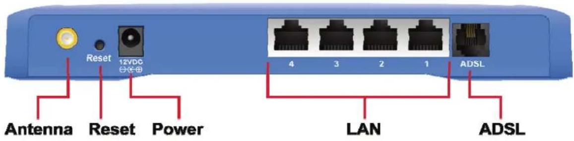
1) Antenna Connector
The antenna connector of the router is reverse SMA connector. It allows you to connecting an external antenna with reverse SMA connector to the router easily.
2) Reset
The Reset button can be used to reset the router or restore to factory defaults.
- If problems occur with your router, press the router's reset button with a pencil tip (for less than 5 seconds) and the router will re-boot itself, keeping your original configurations.
- If problems persist or you experience extreme problems or you forgot your password, press the reset button for longer than 5 seconds and the router will reset itself to the factory default settings (warning: your original configurations will be replaced with the factory default settings)
3) Power Jack
Please plug the power adapter attached with the ADSL Router to the power jack. The power adapter is 12VDC, 1A.
4) Local Area Network (LAN)
The router's 4 LAN ports are where you connect your LAN's PCs, printer servers, hubs and switches etc.
5) ADSL
Connect the supplied RJ-11 telephone line to this port and your ADSL/telephone network.
1.4.2. Front LEDs
On the router's front panel there are LED lights that inform you of the router's current status. Below is an explanation of each LED and its description.

| LED | Light | Status | Description |
| On The router is ready PWR (Green) | |||
| WLAN (Yellow) | Off Wireless LAN is disabledBlinking Wireless traffic is transmitting or receiving | ||
| ADSL (Green) | On Connected to an ADSL DSLAN successfully | ||
| Blinking | No connection | ||
| LAN LNK/ACT (Port 1-4) | On | The LAN cable is connected to the router | |
| Off | No network connection. | ||
| Blinking | Network traffic transferring or receiving through the LAN port | ||
2. Hardware Installation
Step 1. Connect the ADSL Line
Connect the router to your ADSL cable through the supplied RJ-11 telephone line.
Step 2. Connect the router to your LAN network
Connect the router to your PC, hub or switch by attached the Ethernet cable to the LAN port of the router.
Step 3. Connect the Power Adapter to the Router
Connect the power adapter to the power jack on the rear panel of router.
Step4: Check the ADSL LED on the Router
The ADSL LED will be ON if the router is connected to the ADSL cable and receives the ADSL signals successfully. If the LED is blinking, please contact with your ISP (Internet Service Provider) to check the problem.
Note: You must use the power adapter shipped along with the router, do NOT use any other power adapter from other sources.
3. Setup Wizard
This router provides a Setup Wizard tool for user to configure the ADSL settings. This wizard collects some ISP's ADSL settings so that user can easy to configure the router's ADSL settings by only selecting the ISP vendor from the wizard.
If you cannot find your ISP from the wizard, please refer to the Section 5.1 to run the Quick Start wizard in the web management of the router.
Before you start, please check the following items:
- Please make sure that you have connected the ADSL cable to the router correctly. When the ADSL cable is worked normally, the ADSL LED will be on.
- Uninstall all of dial up programs if you have installed previously for the USB modem or other dial up devices.
- It is recommended to configure the router through the Ethernet cable before you have set the wireless functions correctly.
This wizard can be run in Windows 98SE/Me/2000/XP. The following procedures are operated in Windows XP. (Procedures are similar for Windows 98SE/Me/2000.)
-
Insert the CD shipped along with the ADSL router into your CD-ROM drive. The Autorun.exe program should be executed automatically. If not, run Autorun.exe manually from "Autorun" folder in the CD.
-
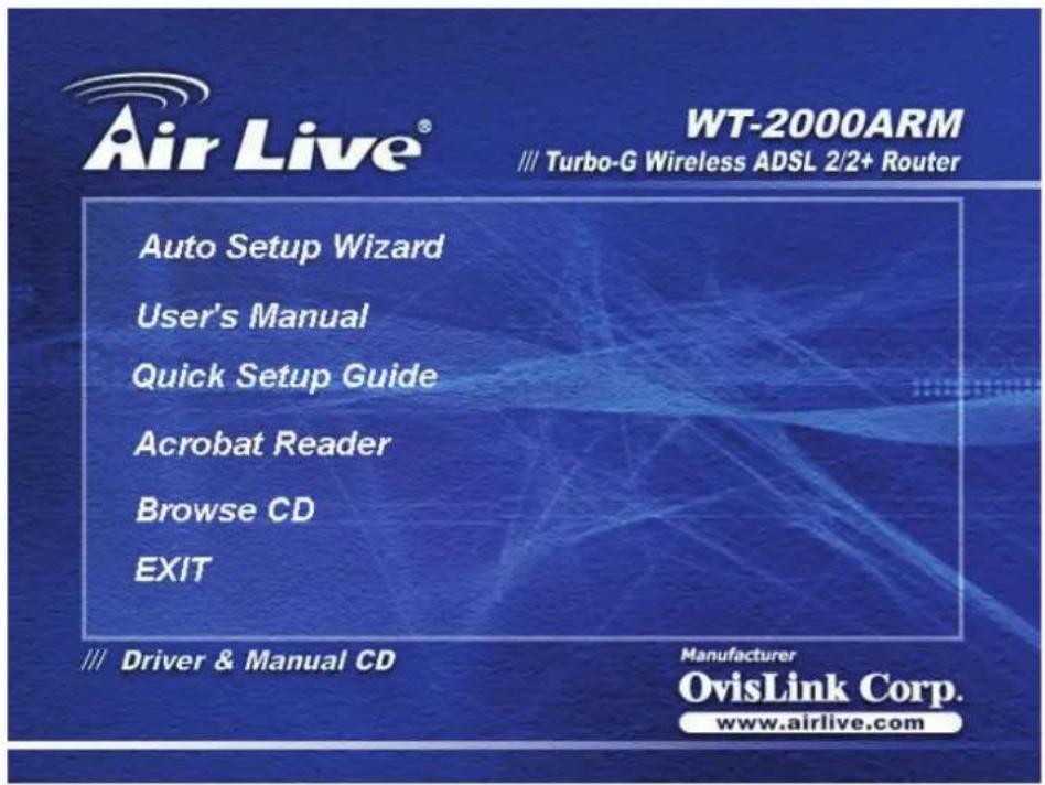
The following screen will be displayed. Click "Setup Wizard".
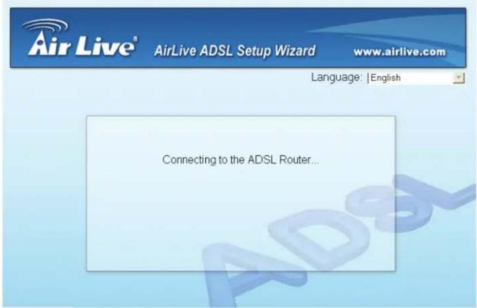
- This wizard will be executed and try to search for the ADSL Router.
- If the router cannot be found, please enter the IP Address and the Password of the router to search again. Click "Next" to continue.
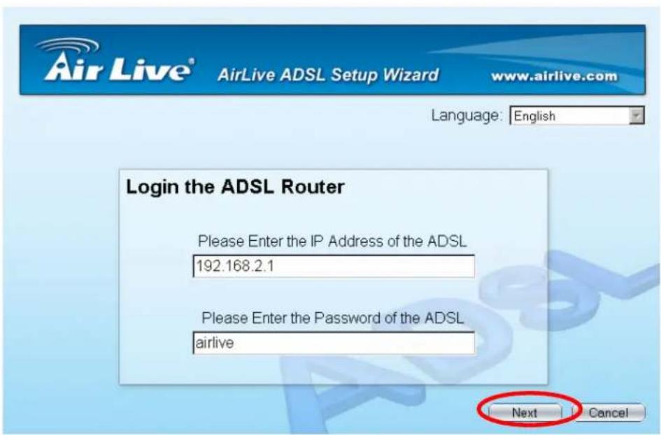
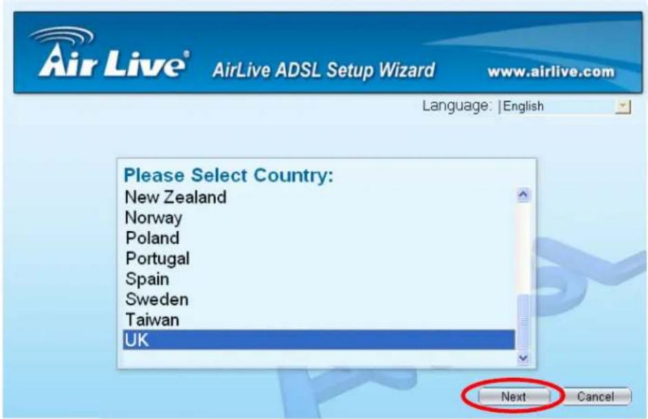
- Please select the country you have installed the ADSL router and click "Next".
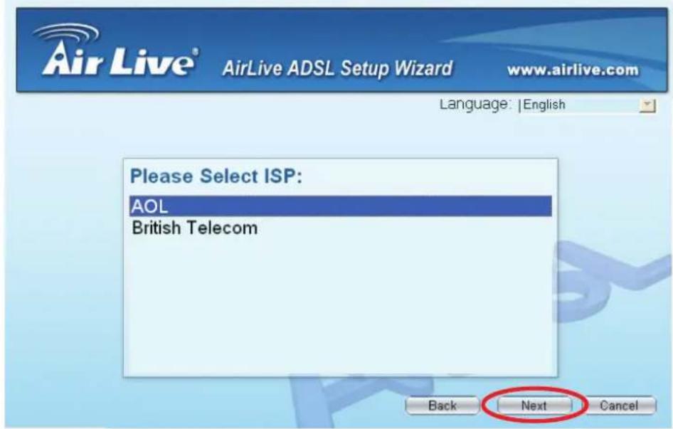
- Please select the ISP (Internet Service Provider) of your ADSL service.
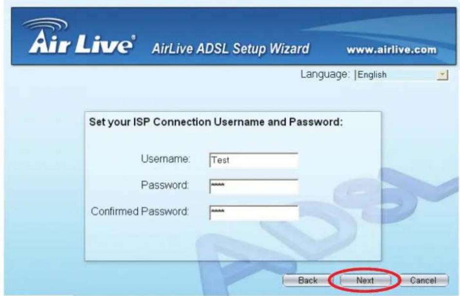
- Enter the Username and Password which your ISP has provided to you if it is needed. Click "Next".
- Click "Save" to save the settings and reboot the router.
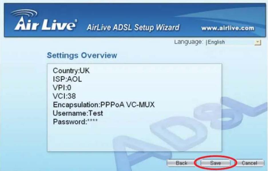
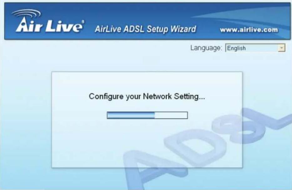
- After saving and rebooting the router, the ISP settings are all finished. This wizard will then help to set your computer to obtain IP Address from the router automatically.
Note1: Using the router to get into the Internet, the IP Address of each PC has to be set in the same subnet as the router. This wizard will help to set the proper IP Address to your computer.
Note2: By default, the router's DHCP Server is enabled. If it is disabled before running the wizard, the wizard will enable the DHCP Server of the router automatically.
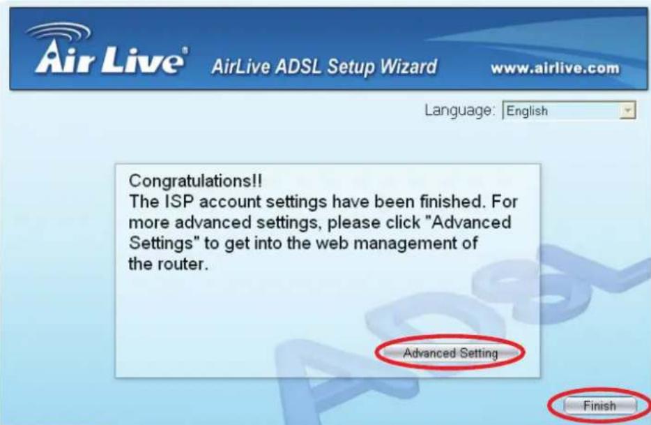
- The ISP settings are all finished. If you want to configure more settings, please click "Advanced Settings" or click "Finish" to close the wizard.
4. IP Address Setting
Using the router to get into the Internet, the PCs in the network must have Ethernet adapter installed and be connected to the router either directly or through a hub or switch. The TCP/IP protocol of each PC has to been installed and the IP Address of each PC has to be set in the same subnet as the router.
The router's default IP Address is 192.168.2.1 and the subnet mask is 255.255.255.0. PCs can be configured to obtain IP Address automatically through the DHCP Server of the router or a fixed IP Address in order to be in the same subnet as the router. By default, the DHCP Server of the router is enabled and will dispatch IP Address to PC from 192.168.2.100 to 192.168.2.200. It is strongly recommended to set obtaining IP address automatically.
This section shows you how to configure your PC's so that it can obtain an IP address automatically for either Windows 95/98/Me, 2000 or NT operating systems. For other operating systems (Macintosh, Sun, etc.), please follow the manual of the operating systems. The following is a step-by-step illustration on how to configure your PC to obtain an IP address automatically for Windows XP, Windows 2000, Windows 95/98/Me, and Windows NT.
Windows XP
- Click the Start button and select Control Panel and then double click Network Connections. The Network Connections window will appear.
- Right click on the Local Area Connection icon and select Properties. The Local Area Connection window will appear.
-
Check your list of Network Components. You should see Internet Protocol [TCP/IP] on your list. Select it and click the Properties button.
-
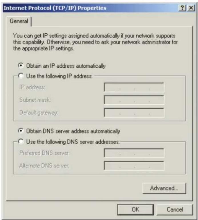
In the Internet Protocol (TCP/IP) Properties window, select Obtain an IP address automatically and Obtain DNS server address automatically as shown on the following screen.
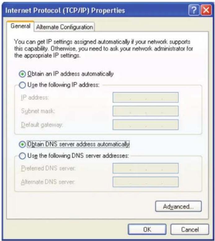
- Click OK to confirm the setting. Your PC will now obtain an IP address automatically from your router's DHCP server.
Note: Please make sure that the router's DHCP server is the only DHCP server available on your LAN.
Windows 2000
- Click the Start button and select Settings, then click Control Panel. The Control Panel window will appear.
- Double-click Network and Dial-up Connections icon. In the Network and Dial-up Connection window, double-click Local Area Connection icon. The Local Area Connection window will appear.
- In the Local Area Connection window, click the Properties button.
- Check your list of Network Components. You should see Internet Protocol [TCP/IP] on your list. Select it and click the Properties button.
- In the Internet Protocol (TCP/IP) Properties window, select Obtain an IP address automatically and Obtain DNS server address automatically as shown on the following screen.
- Click OK to confirm the setting. Your PC will now obtain an IP address automatically from your Broadband Router's DHCP server.
Note: Please make sure that the router's DHCP server is the only DHCP server available on your LAN.
Windows 95/98/Me
- Click the Start button and select Settings, then click Control Panel. The Control Panel window will appear.
- Double-click Network icon. The Network window will appear.
- Check your list of Network Components. If TCP/IP is not installed, click the Add button to install it now. If TCP/IP is installed, go to step 6.
- In the Network Component Type dialog box, select Protocol and click Add button.
- In the Select Network Protocol dialog box, select Microsoft and TCP/IP and then click the OK button to start installing the TCP/IP protocol. You may need your Windows CD to complete the installation.
-
After installing TCP/IP, go back to the Network dialog box. Select TCP/IP from the list of Network Components and then click the Properties button.
-
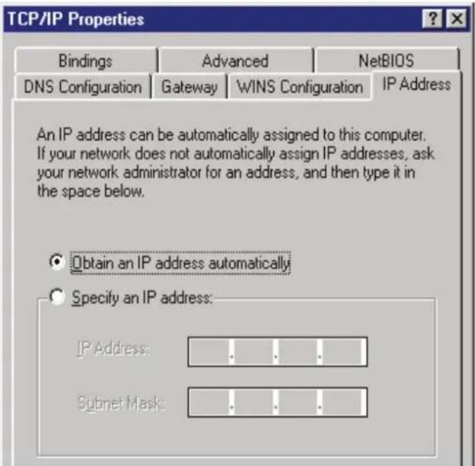
Check each of the tabs and verify the following settings:
Bindings: Check Client for Microsoft Networks and File and printer sharing for Microsoft Networks.
Gateway: All fields are blank.
DNS Configuration: Select Disable DNS.
WINS Configuration: Select Disable WINS Resolution.
IP Address: Select Obtain IP address automatically.
- Reboot the PC. Your PC will now obtain an IP address automatically from your router's DHCP server.
Note: Please make sure that the router's DHCP server is the only DHCP server available on your LAN.
Windows NT
- Click the Start button and select Settings, then click Control Panel. The Control Panel window will appear.
- Double-click Network icon. The Network window will appear. Select the Protocol tab from the Network window.
- Check if the TCP/IP Protocol is on your list of Network Protocols. If TCP/IP is not installed, click the Add button to install it now. If TCP/IP is installed, go to step 5.
- In the Select Network Protocol window, select the TCP/IP Protocol and click the Ok button to start installing the TCP/IP protocol. You may need your Windows CD to complete the installation.
-
After you install TCP/IP, go back to the Network window. Select TCP/IP from the list of Network Protocols and then click the Properties button.
-
Check each of the tabs and verify the following settings:
IP Address: Select Obtain an IP address from a DHCP server.
DNS: Let all fields are blank.
WINS: Let all fields are blank.
Routing: Let all fields are blank.
![Microsoft TCP/IP Properties IP Address DNS WINS Address Routing An IP address can be automatically assigned to this network card by a DHCP server. If your network does not have a DHCP server, ask your network administrator for an address, and then type it in the space below. Adapter: [1] Realtek RTL8139/810X Family PCI Fast Ethernet Adapter Obtain an IP address from a DHCP server Specify an IP address IP Address: ... Subnet Mask: ... Default Gateway: ... Advanced... OK Cancel Apply](/content/2026/05/843551/images/310bde6b1145c5d7fa3b643dd0df2ded272cc333e11effa43bf13448dd3378f6.jpg)
- Click OK to confirm the setting. Your PC will now obtain an IP address automatically from your Broadband Router's DHCP server.
Note: Please make sure that the router's DHCP server is the only DHCP server available on your LAN.
5. Web Management Configuration
Once you have configured your PCs to obtain an IP address automatically, the router's DHCP server will automatically give your LAN clients an IP address. By default the router's DHCP server is enabled so that you can obtain an IP address automatically. To see if you have obtained an IP address, see Appendix A.
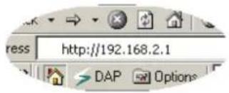
Once your PC has obtained an IP address from your router, enter the default IP address 192.168.2.1 (router's IP address) into your PC's web browser and press
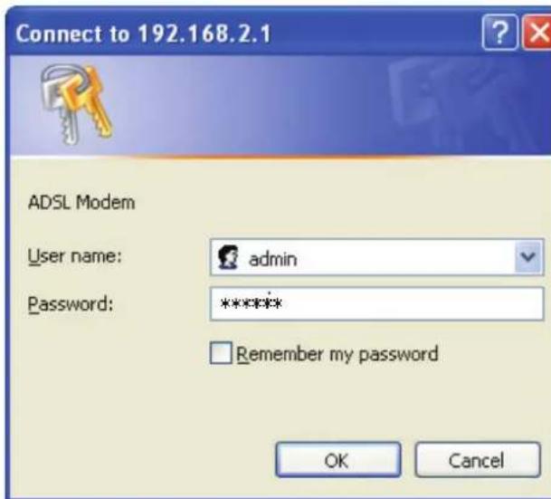
The login screen below will appear. Enter the "User Name" and "Password" and then click
The HOME page screen below will appear. The Home Page is divided into seven sections: Quick Start, Interface Setup, Advanced Setup, Access Management, Maintenance, Status and Help.
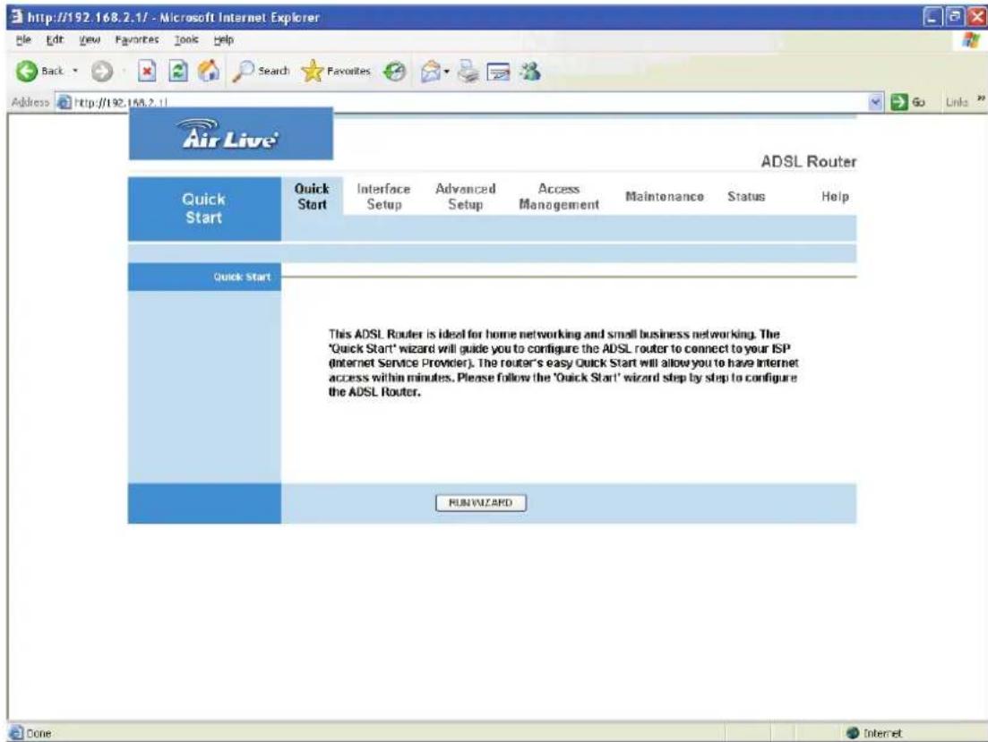
Quick Start (Section 5.1)
Follow the setup process in the Quick Start, you can quickly set the router as an Internet Access device.
Interface Setup (Section 5.2)
It allows you to configure the Internet, LAN and Wireless access.
Advanced Setup (Section 5.3)
This section contains configurations for the router's advanced functions such as Firewall, Virtual Server, DMZ, ADSL Mode, ADSL Type, etc.
Access Management (Section 5.4)
It allows you to configure ACL, IP Filter, SNMP, UPnP and DDNS functions.
Maintenance (Section 5.5)
If you want to change the administrator's password, restart the router, update the firmware, diagnose the connection or change the Tome Zone of the router, please select this menu.
Status (Section 5.6)
The router's setup information, system log and some statistics can be viewed here.
Help
If you want to know about the settings of the router quickly, please refer to the description in the Help menu.
5.1. Quick Start
The Quick Start section is designed to get you using the router as quickly as possible. Before configuring the router, please check with your ISP (Internet Service Provider) what kind of the service is provided such as PPPoE, PPPoA or RFC1483/2684. Gather the information as illustrated in the following table and keep it for reference.
| PPPoE VPI/VCI, VC- | -based/LLC-based multiplexing, Username, Password (and Service Name). |
| PPPoA VPI/VCI, VC- | -based/LLC-based multiplexing, Username, Password. |
| RFC1483 Bridged VPI | I/VCI, VC-based/LLC-based multiplexing to use Bridged Mode. |
| RFC1483 Routed VPI | I/VCI, VC-based/LLC-based multiplexing, IP Address, Subnet Mask, Gateway Address, and Domain Name System (DNS) IP Address (It is a fixed IP Address). |
In the Quick Start, click "Run Wizard" to start the configuration.
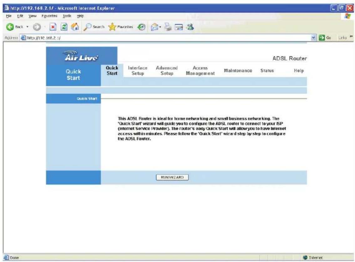
Please follow the steps in the setup wizard to complete the configuration of the Internet connection.
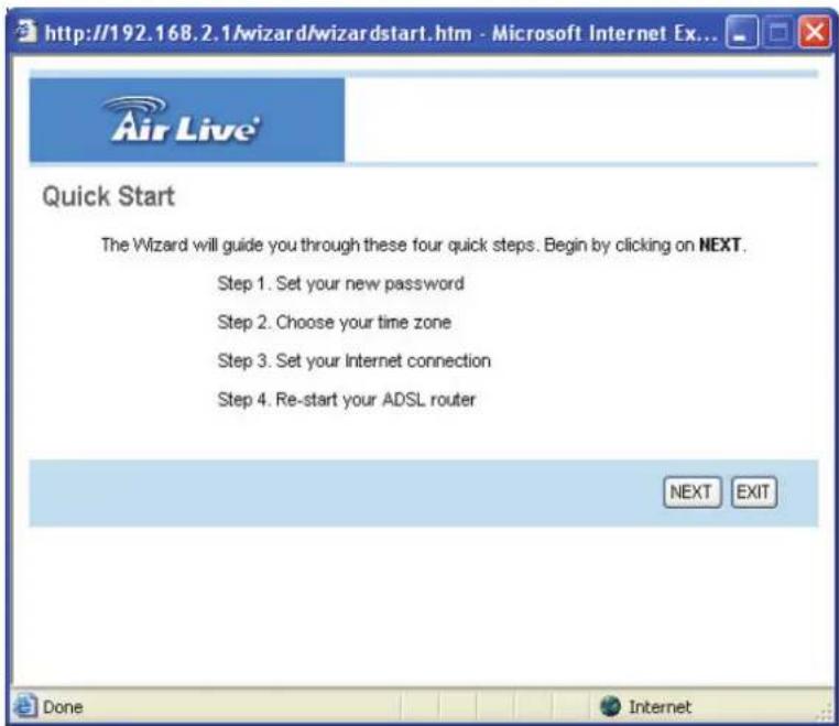
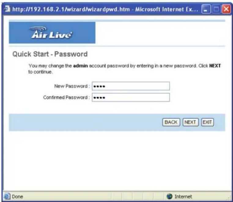
Step 1: Set your new password
Please enter the new password and confirm the password again.
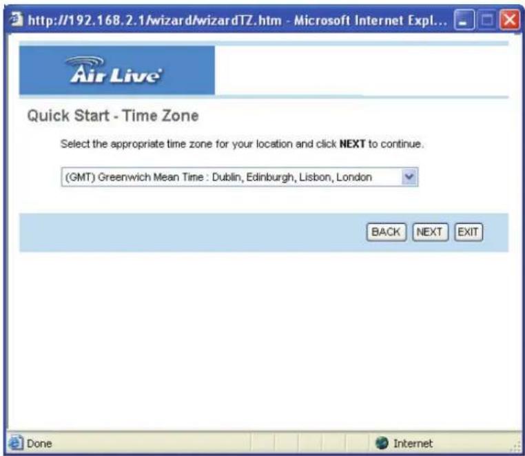
Step 2: Choose your tome zone
Please select the tome zone where you are located.
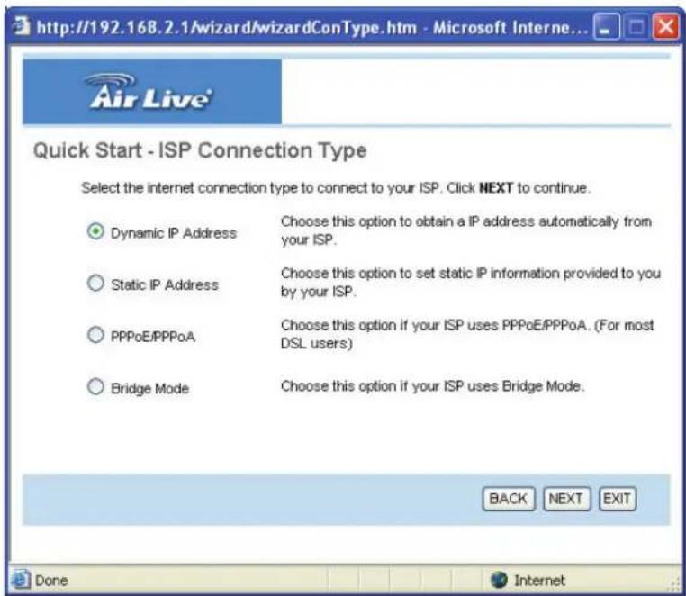
Step 3: Set your Internet connection
Please check with your ISP the connection type of the ADSL line.
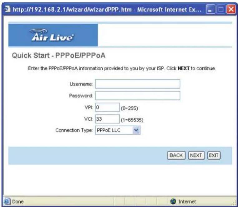
Step 4: Input the data supplied by your ISP
To know more about the explanation of each setting, please refer to Section 5.2.
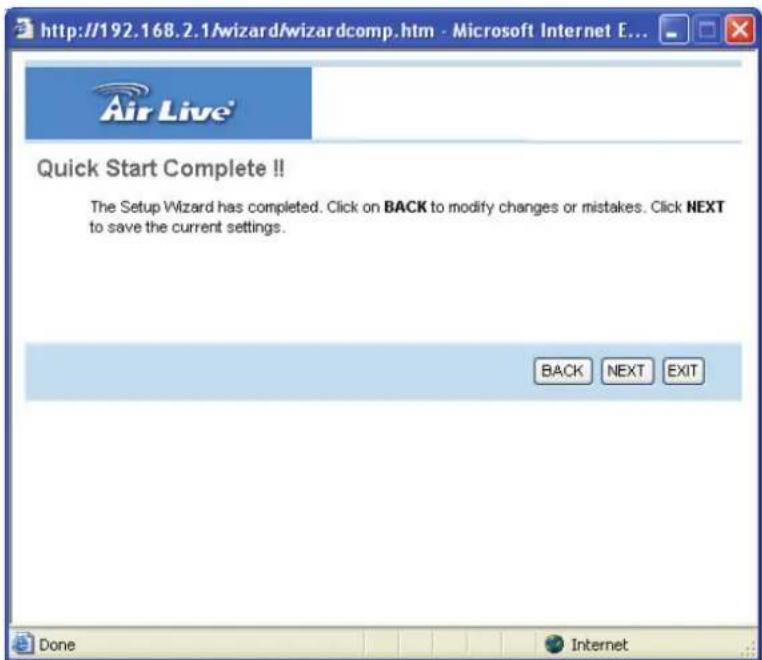
Step 5: Re-start your ADSL router
Click "Next" to save the settings and restart the router.
5.2. Interface Setup
5.2.1. Internet
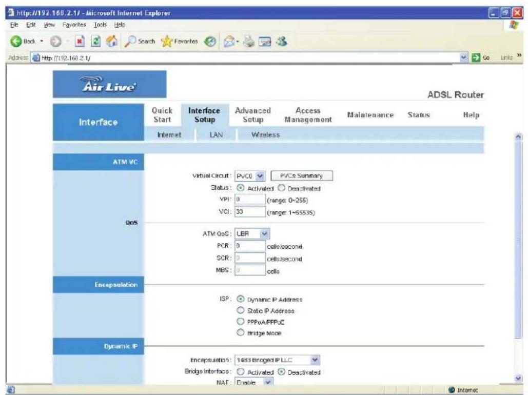
Parameter Description
Virtual Circuit VPI (Virtual Path Identifier) and VCI (Virtual Channel Identifier define a virtual circuit.
| VPI | VPI is a virtual path determines the way an ATM cell should be routed. The VPI is an 8-bit (in UNI) or 12-bit (in NNI) number that is included in the header of an ATM cell. The valid range for the VPI is 0 to 255. Enter the VPI assigned by the ISP. |
Parameter Description
VCI VCI is the label given to an ATM VC to identify it and determine its destination. The VCI is a 16-bit number that is included in the header of an ATM cell. The valid range for the VCI is 32 to 65535. Enter the VCI assigned by the ISP.
ATM QoS CBR (Constant Bit Rate) – This class is used for emulating circuit switching. The cell rate is constant with time. Select CBR to specify fixed (always on) bandwidth for voice or data traffic. UBR (Unspecified Bit Rate) – Select UBR for applications that are non-time sensitive, such as e-mail.
rtVBR (real time Variable Bit Rate) – This class is similar to nrtVBR but is designed for applications that are sensitive to cell-delay variation. Examples for real-time VBR are voice with speech activity detection (SAD) and interactive compressed video.
nrtVBR (non-real time Variable Bit Rate) – This class allows users to send traffic at a rate that varies with time depending on the availability of user information. Statistical multiplexing is provided to make optimum use of network resources. Multimedia e-mail is an example of nrtVBR.
PCR Divide the DSL line rate (bps) by 424 (the size of an ATM cell) to find the PCR (Peak Cell Rate). This is the maximum rate at which the sender can send cells.
SCR SCR (Sustain Cell Rate) is the average rate, as measured over a long interval, in the order of the connection lifetime.
Parameter Description
MBS MBS (Maximum Burst Size) refers to the maximum number of cells that can be sent at the peak rate. Type the MBS, which is less than 65535.
- Encapsulation
The router can be connected to your service provider in any of the following ways.
Parameter Description
Dynamic IP Address Obtain an IP address automatically from your service provider.
Static IP Address Uses a static IP address. Your service provider gives a static IP address to access Internet services.
PPPoE/PPPoA PPPoE (PPP over Ethernet) and PPPoA (PPP over ATM) are common connection methods used for xDSL.
Bridge Mode Bridge Mode is a common connection method used for
• Dynamic IP Address/Static IP Address/PPPoE/PPPoA/Bridge Mode
After you have selected the ISP Type, this web page will be varied depending on the ISP Type you select. You have to continue setting some parameters. Please refer to the following table for the explanation of each parameter.
Parameter Description
User Name Enter the username exactly as your ISP assigned.
Password Enter the password that your ISP has assigned to you.
Encapsulation Please check with your ISP the method of multiplexing.
In Bridge Mode, please select "1483 Bridge IP LLC" or "1483 Bridge IP VC-Mux". In PPPoE/PPPoA mode, please select "PPPoE LLC", "PPPoE VC-Mux", "PPPoA LLC", or "PPPoA VC-Mux".
Connection Always On – The connection will be kept always on. If
the connection is interrupted, the router will re-connect automatically.
Connect On-Demand – Only connect when you want to surf the Internet. “Close if idle for xx minutes” is set to stop the connection when the network traffic is not sending or receiving after an idle time.
TCP MSS Option The TCP MSS Option enables the configuration of the maximum segment size (MSS) for transient packets that traverse a router, specifically TCP segments in the SYN bit set, when PPPoE is being used in the network. Please specify the MSS range from 100 to 1452 bytes or 0 byte as the default value.
Parameter Description
Get IP Address Choose Static or Dynamic IP Address. If Static IP is selected, please set the IP Address, Subnet Mask and Gateway obtained from your ISP.
Static IP Address Enter the IP Address assigned by your ISP.
IP Subnet Mask Enter the Subnet Mask assigned by your ISP.
Gateway Enter the Gateway assigned by your ISP.
NAT NAT (Network Address Translation), an Internet standard that enables a local-area network (LAN) to use one set of IP addresses for internal traffic and a second set of addresses for external traffic. When NAT is enabled, the router will help to make all necessary IP address translations for the PC connected to the router to access the Internet.
Default Route When "Default Router" is enabled, all the packets for
destinations not known by the router's routing table are sent to the default route. By default, it is enabled.
TCP MTU Option MTU (Maximum Transmission Unit) determine the maximum size of each packet in any transmission within the network. Please specify the MTU range from 100 to 1500 bytes or 0 byte as the default value.
Dynamic Route Dynamic routing allows routing tables in routers to change as the possible routes change. This router supports RIP1, RIP2-B and RIP2-M protocols for dynamic routing. After the RIP protocol is selected, please choose the RIP direction from “None”, “Both”, “IN Only” or “OUT Only”.
Parameter Description
Multicast Specify the method of transmitting data simultaneously to many receivers. Please select "IGMP v1" or "IGMP v2" as the multicast protocol or select "Disabled" to disable the function.
5.2.2. LAN
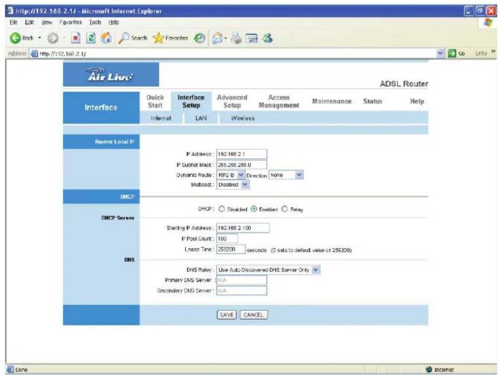
- Router Local IP
Parameter Description
IP Address Enter the IP Address of the ADSL router for the local user to access the router's web page. By default, the IP Address is 192.168.2.1.
Parameter Description
IP Subnet Mask Enter the Subnet Mask of the ADSL router. By default, the Subnet Mask is 255.255.255.0.
Dynamic Route Dynamic routing allows routing tables in routers to change as the possible routes change. This router supports RIP1, RIP2-B and RIP2-M protocols for dynamic routing. After the RIP protocol is selected, please choose the RIP direction from "None", "Both", "IN
Only" or "OUT Only".
Multicast Specify the method of transmitting data simultaneously to many receivers. Please select "IGMP v1" or "IGMP v2" as the multicast protocol or select "Disabled" to disable the function.
• DHCP
Parameter Description
DHCP You can enable or disable the DHCP server. By enabling the DHCP server the router will automatically give your LAN clients an IP address. If the DHCP is not enabled then you'll have to manually set your LAN client's IP addresses.
Starting IP Address If the DHCP Server is enabled, please set the "Starting IP Address" which will be the first IP Address assigned to the LAN client. By default, the "Starting IP Address" is 192.168.2.100.
IP Pool Count You can select a particular IP address range for your DHCP server to issue IP addresses to your LAN Clients. By default, the "IP Pool Count" is 100. The IP range is starting from IP 192.168.2.100 to 192.168.2.199.
Parameter Description
Lease Time In the Lease Time setting you can specify the time period that the DHCP Server lends an IP address to your LAN clients. The DHCP will change your LAN client's IP address when this time threshold period is terminated.
DNS Relay A Domain Name System (DNS) server is like an index of IP addresses and Web addresses. If you type a Web address into your browser, such as "www.router.com", a
DNS server will find that name in its index and the matching IP address. Please select "Use Auto Discovered DNS Server Only" to auto set the DNS Server. If there is a DNS server that you would rather to use, please select "Use Discovered DNS Server Only" and you need to specify the IP address of that DNS server.
Primary DNS Server Enter the ISP's DNS Server IP Address; or you can specify your own preferred DNS Server IP Address.
Secondary DNS Server This is optional. You can enter another DNS Server's IP Address as a backup. The secondary DNS will be used should the Primary DNS fail.
5.2.3. Wireless
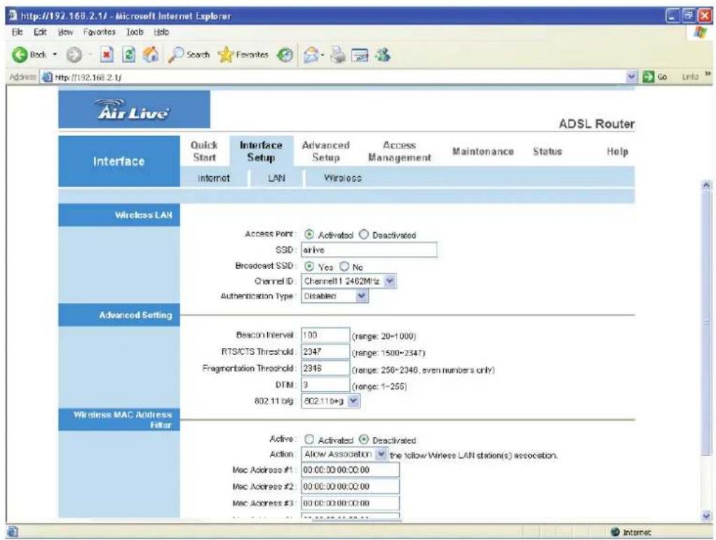
- Wireless LAN
Parameter Description
Access Point Activated or deactivated the wireless function of the router. When it is activated, the router will be an access point for other wireless clients to connect wirelessly.
SSID The SSID (up to 32 printable ASCII characters) is the unique name identified in a WLAN. The ID prevents the unintentional merging of two co-located WLANs. The default SSID of the router is “airlive”.
Parameter Description
Broadcast SSID Select "Yes" to make the SSID to be visible so wireless
clients can scan the router within the network. Select "No" if you want to hide the SSID of the router. Wireless clients have to set the same SSID of the router in order to access the network.
Channel ID The radio channel used by the wireless LAN. All devices in the same wireless LAN should use the same channel.
Authentication Type To prevent unauthorized wireless clients from accessing the router, this router supports WEP, WPA-PSK and WPA2-PSK authentication type. If the router has enabled the authentication, all the wireless clients' settings have to be consistent with the router for building the connection.
• WEP/WPA-PSK/WPA2-PSK
Parameter Description
WEP-64Bits WEP is less level of security than WPA. WEP supports 64-bit and 128-bit key lengths to encrypt the wireless data. The longer key length will provide higher security. When “WEP-64Bits” is selected, you have to enter exactly 5 ASCII characters (“a-z” and “0-9”) or 10 hexadecimal digits (“0-9”, “a-f”) for each Key (1-4).
WEP-128Bits When "WEP-128Bits" is selected, you have to enter exactly 13 ASCII characters ("a-z" and "0-9") or 26 hexadecimal digits ("0-9", "a-f") for each Key (1-4).
Parameter Description
WPA-PSK WPA-PSK is suitable for home and small business. It
uses TKIP for data encryption. When "WPA-PSK" is selected, please enter 8-64 characters as the "Pre-Shared Key".
WPA2-PSK WPA2-PSK is also for home and small business. The difference between WPA-PSK and WPA2-PSK is that WPA2-PSK provides data encryption via the AES. In contrast, WPA-PSK uses Temporal Key Integrity Protocol (TKIP). WPA2-PSK offers the highest level of security available. When “WPA2-PSK” is selected, please enter 8-64 characters as the “Pre-Shared Key”.
- Advanced Setting
Parameter Description
Beacon Interval The interval of time that this wireless router broadcast a beacon. Beacon is used to synchronize the wireless network. The range for the beacon period is between 20 and 1000 with a typical value of 100 (milliseconds).
RTS/CTS Threshold When the packet size is smaller than the RTS threshold, the wireless router will not use the RTS/CTS mechanism to send this packet. The range is from 1500 to 2347.
Fragmentation Fragment Threshold specifies the maximum size of packet during the fragmentation of data to be transmitted. If you set this value too low, it will result in bad performance. Enter a value from 256 to 2346.
DTIM Determines the interval the Access Point will send its broadcast traffic. The range is from 1 to 255 and the default value is 3 beacons.
Parameter Description
802.11b/g 802.11 b – This router will only work in 802.11b mode. If there are only 802.11b wireless clients in the network,
you can set the router to this mode.
802.11 g – This router will only work in 802.11g mode. If there are only 802.11g wireless clients in the network, you can set the router to this mode.
802.11 b+g – This router will support 802.11b and 802.11g communications simultaneously. It is recommended to set this mode.
- Wireless MAC Address Filter
Parameter Description
Active This router can prevent the wireless clients from accessing the wireless network by checking the MAC Address of the clients. If you enable this function, please set the MAC Address of the wireless clients that you want to filter.
Action Allow Association – Only allow the wireless clients with the MAC Address you have specified can access to the router.
Deny Association – The wireless clients with the MAC Address you have specified will be denied accessing to the router.
Mac Address #1-8 Please enter the MAC Address of the wireless clients for the filtering control.
5.3. Advanced Setup
5.3.1. Firewall
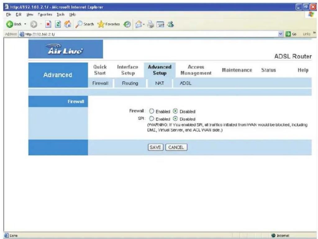
Parameter Description
Firewall When you enable the firewall function, it will protect you
from following attacks of WAN side:
• SYN flooding attack
- Ping of Death
- Teardrop
- Land attack
SPI If you enable SPI, all traffics initiated from WAN site will
be blocked including DMZ, Virtual Server, etc.
5.3.2. Routing
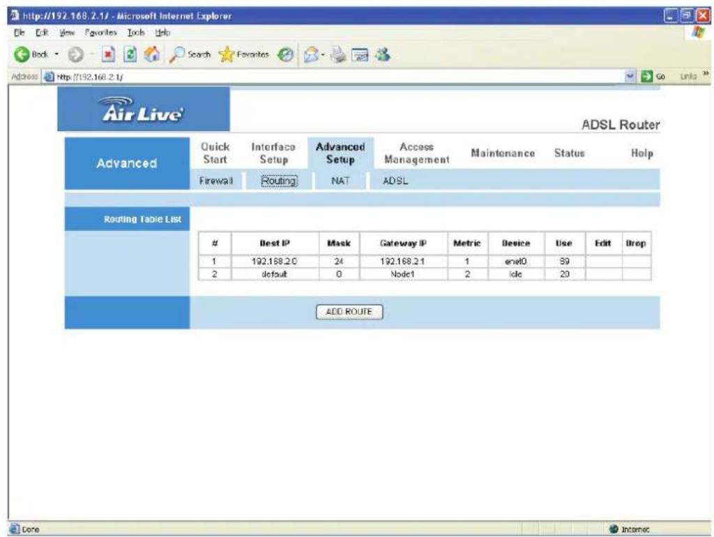
- Routing Table List
You can see the current routing table of the router here. If you want to add another routing rule, please click "ADD ROUTE".
Parameter Description
Dest IP Show the IP Address of the destination LAN.
Mask Show the Subnet Mask of the destination LAN. If it shows
“8” that means the Subnet Mask is “255.0.0.0”; “16”
means the Subnet Mask is "255.255.0.0"; "24" means the Subnet Mask is "255.255.255.0".
Parameter Description
Gateway IP The next stop gateway of the path toward the destination
LAN. This is the IP of the neighbor router that this router should communicate with on the path to the destination LAN.
Metric The number of hops (routers) to pass through to reach the destination LAN. It must be between 1 and 15.
Device Show the interface that go to the next hop (router), such as LAN port.
Use The counter for access time.
Edit Edit the route, this icon is not shown for system default route.
Drop Drop the route, this icon is not shown for system default route.
- Add Route
If you have another router with a LAN-to-LAN connection, you may need to create a static routing on the router that is the gateway to Internet.
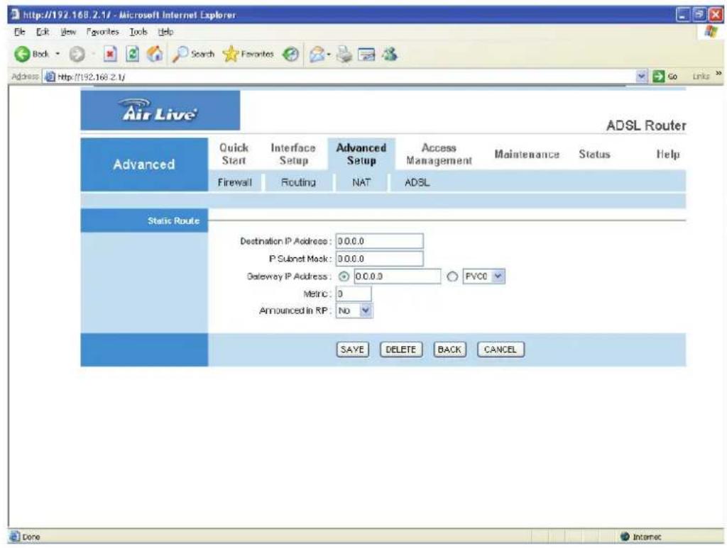
Parameter Description
Destination IP Address Enter the IP Address of the destination LAN.
IP Subnet Mask Enter the Subnet Mask address of the destination LAN.
Gateway IP Address This is the gateway IP Address where packets are sent.
Metric The number of hops (routers) to pass through to reach the destination LAN. It must be between 1 and 15.
Announced in RIP Select "Yes", this routing path will be propagated to other hosts through RIP broadcasts. Select "No", this routing path will be kept private and it is not included in RIP broadcasts.
5.3.3. NAT
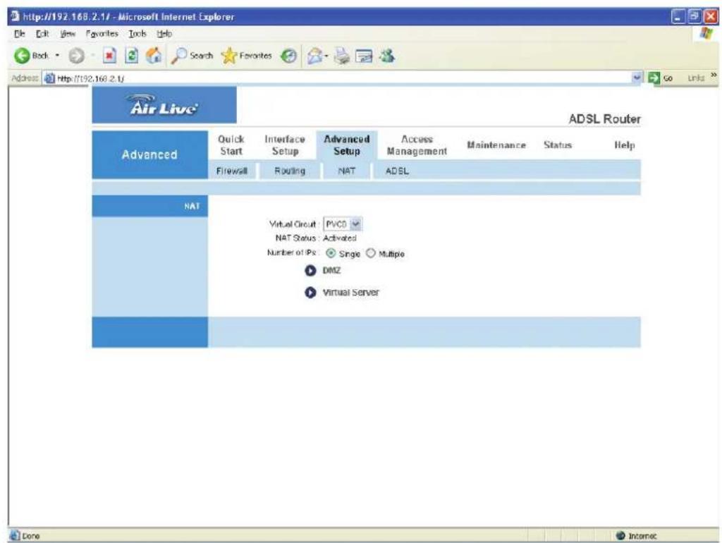
5.3.3.1. NAT
Network Address Translation (NAT) allows multiple users at your local site to access the Internet through a single Public IP Address or multiple Public IP Addresses. NAT provides Firewall protection from hacker attacks and has the flexibility to allow you to map Private IP Addresses to Public IP Addresses for key services such as Websites and FTP.
Parameter Description
Virtual Circuit VPI (Virtual Path Identifier) and VCI (Virtual Channel Identifier define a virtual circuit.
NAT Status The activated or deactivated status for the NAT function will be shown here.
Number of IPs Select "Single" if you only have a public IP Address. Select "Multiple" if you have multiple IP Addresses.
5.3.3.2. DMZ
The DMZ Host is a local computer exposed to the Internet. When setting a particular internal IP Address as the DMZ Host, all incoming packets will be checked by the firewall and NAT algorithms then passed to the DMZ Host.
For example, if you have a local client PC that cannot run an Internet application (e.g. Games) properly from behind the NAT firewall, then you can open the client up to unrestricted two-way Internet access by defining a DMZ Host.
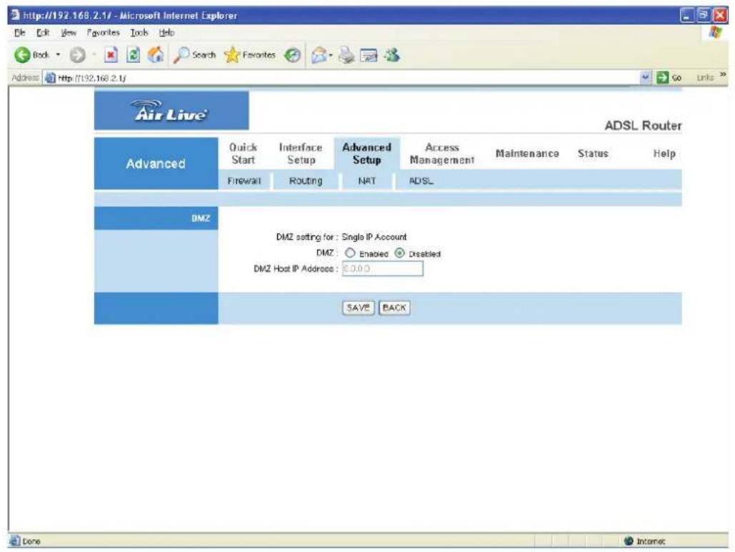
Parameter Description
DMZ setting for Show the DMZ setting is for single or multiple IP Addresses.
DMZ Enable or disable the DMZ function.
DMZ Host IP Address Enter a static IP Address to the DMZ Host. This IP Address will be exposed to the Internet.
5.3.3.3. Virtual Server
Use the Virtual Server function when you want different servers/clients in your LAN to handle different service/Internet application type (e.g. Email, FTP, Web server etc.) from the Internet. Computers use numbers called port numbers to recognize a particular service/Internet application type. The Virtual Server allows you to re-direct a particular service port number (from the Internet/WAN) to a particular LAN private IP Address and its service port number.
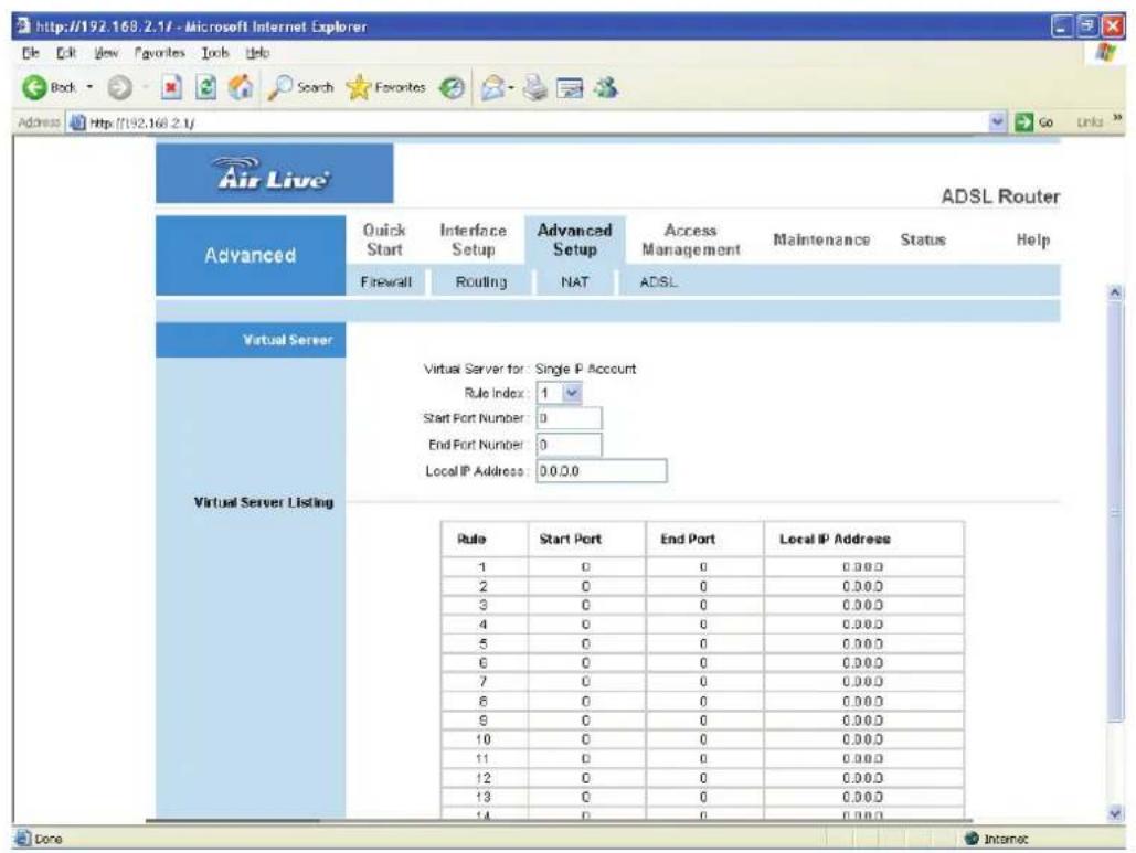
Parameter Description
Virtual Server for Show the Virtual Server setting is for single or multiple IP Addresses.
Rule Index Choose the rule number.
Start Port Number Enter the start port number.
End Port Number Enter the end port number.
Parameter Description
Local IP Address It is recommended to enter a static IP Address for the server here. If the server's IP Address is obtained from DHCP Server, the IP Address may be changed dynamically and will cause problem on this feature. Please assign a static IP Address to the server and make sure that the IP Address is not in the range of IP Addresses that the DHCP Server will assign.
5.3.4. ADSL
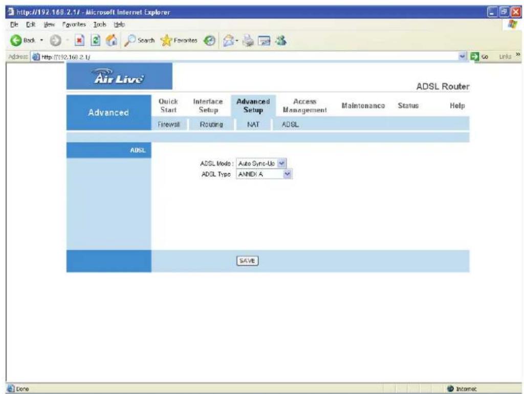
Parameter Description
ADSL Mode The default setting is "Auto Sync-Up". This mode will automatically detect the ADSL mode including ADSL2+, ADSL2, G.DMT, T1.413 and G.lite. If you are not sure how to select the ADSL mode, please contact with your ISP.
ADSL Type Check with your ISP about the ADSL type of the DSLAM device they use.
5.4. Access Management
5.4.1. ACL
If you want to restrict users from accessing certain Internet applications/services such as Internet websites, email, FTP etc., then this is the place to set that configuration. Access Control allows users to define the traffic type permitted in your LAN or WAN. You can control which computer can have access to these services by entering the IP Address of the computer.
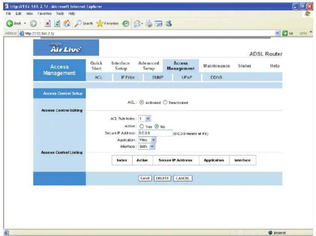
Parameter Description
ACL Activate or deactivate the Access Control function. When
you have activated the function, please do make sure that you have designated the available applications/services or you will be denied to access all the services.
ACL Rule Index This is the item number to record the setting rule.
Parameter Description
Secure IP Address The default 0.0.0.0 allows any user to use this service to remotely manage the router. Type an IP Address to restrict access to a user with a matching IP Address.
Application Choose the services that you permit to use in your LAN or WAN interface. These services include Web, Telnet, Ping, FTP and SNMP.
Interface Select the interface that the user is allowed to use services through it. It includes LAN, WAN or Both.
5.4.2. IP Filter
You can forbid some users accessing to the Web Management of the router by entering the IP Addresses here. The default IP 0.0.0.0 allows any user to use the service to remotely manage the router.
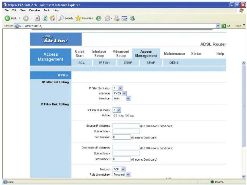
- IP Filter Set Editing
Parameter Description
IP Filter Set Index This is the item number to record the setting.
Interface Select which channel (PVC) to configure.
Direction Select the access to the Internet (Outgoing) or from the Internet (Incoming), or Both.
• IP Filter Rule Editing
Parameter Description
IP Filter Rule Index This is the item number to record the setting rule.
Active Select "Yes" to enable the current rule, select "No" to cancel the current rule.
Source IP Address Enter the start IP Address which will be monitored.
Subnet Mask Enter the Subnet Mask based on the Source IP Address.
Port Number LAN users use port numbers to distinguish one network application over another such as 21 is for FTP service. The port number range is from 0 to 65535. It is recommended that this option be configured by an advanced user.
Destination IP Address Enter the start IP Address which will be monitored.
Subnet Mask Enter the Subnet Mask based on the Destination IP Address.
Port Number This is the port or port ranges that define the application.
Parameter Description
Protocol It is the packet protocol type used by the application.
Please select "TCP", "UDP" or "ICMP". For example, FTP service, you have to select "TCP".
Rule Unmatched Select action for the traffic unmatching current rule.
"Forward" is to leave it pass through; "Next" is to check it by the next rule.
- IP Filter Listing
The IP Filter Listing will list the IP Filter rules you have configured. You can review the settings here.
5.4.3. SNMP
Simple Network Management Protocol (SNMP) is a popular protocol for network management. It is used for collecting information and configuring the network devices. This router supports SNMP agent function, which allows a manager station to manage and monitor the router through the network.
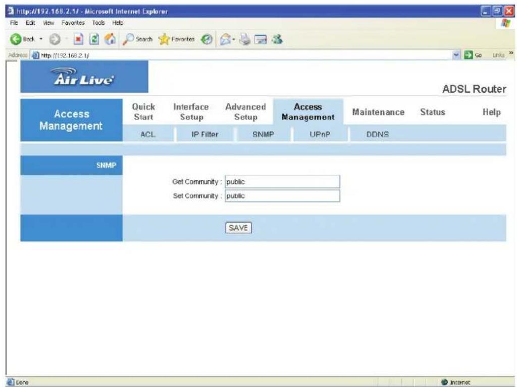
Parameter Description
Get Community Enter the password for the incoming Get- and GetNext requests from the management station.
Set Community Enter the password for a Set request to configure the router.
5.4.4. UPnP
When the UPnP function is enabled, the router can be detected by UPnP compliant system such as Windows XP. The router will be displayed in the Neighborhood of Windows XP, so you can directly double click the router or right click the router and select "Invoke" to configure the router through web browser.
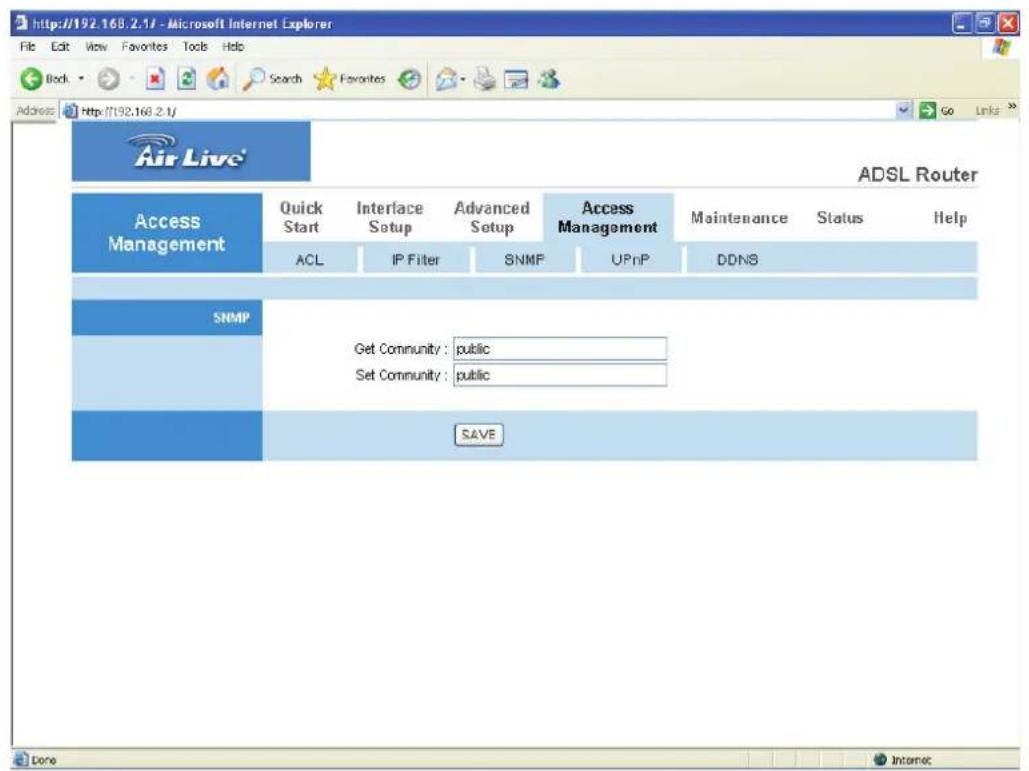
Parameter Description
UPnP Activated or deactivated the UPnP function.
Auto-configured Select this check box to allow UPnP-enabled applications to automatically configure the router so that they can communicate through the router, for example by using NAT traversal, UPnP applications automatically reserve a NAT forwarding port in order to communicate with another UPnP enabled device; this eliminates the need to manually configure port forwarding for the UPnP enabled application.
5.4.5. DDNS
DDNS allows you to map the static domain name to a dynamic IP address. You must get an account, password and your static domain name from the DDNS service providers.
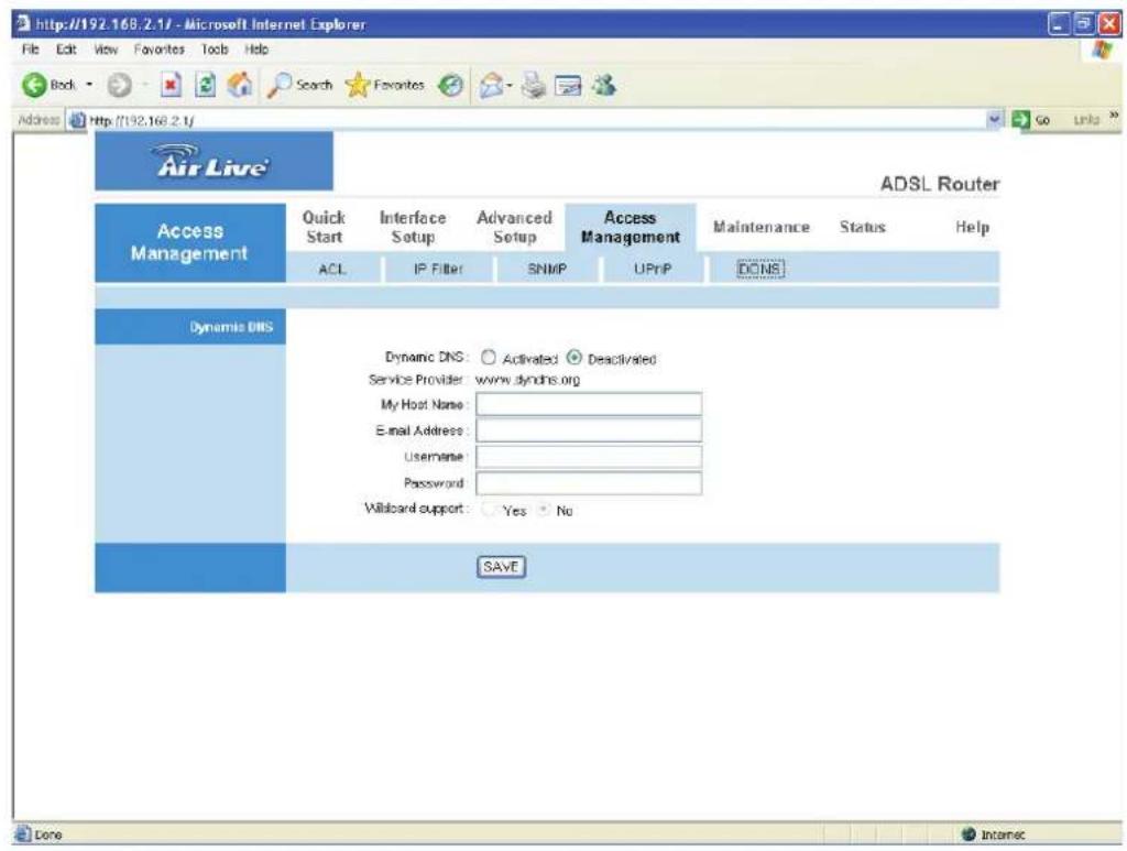
Parameter Description
Dynamic DNS Activated or deactivated the DDNS function.
Service Provider This router supports DynDNS service provider.
My Host Name Enter the domain name assigned to your router by the service provider.
E-mail Address Enter the E-mail address assigned by DDNS service provider.
Username
Enter
your
username.
Parameter Description
Password Enter the password you set for the DDNS service.
Wildcard Support Enable or disable the wildcard to stand for some characters.
5.5. Maintenance
5.5.1. Administrator
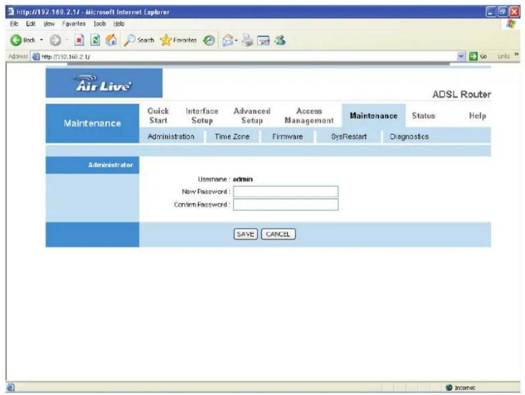
Parameter Description
Username The username of the router is "admin" by default.
New Password Enter up to 30-digit of the new password.
Confirm Password Enter the new password again to confirm the setting.
5.5.2. Time Zone
The Time Zone allows your router to set its time; this will affect function such as System Log.
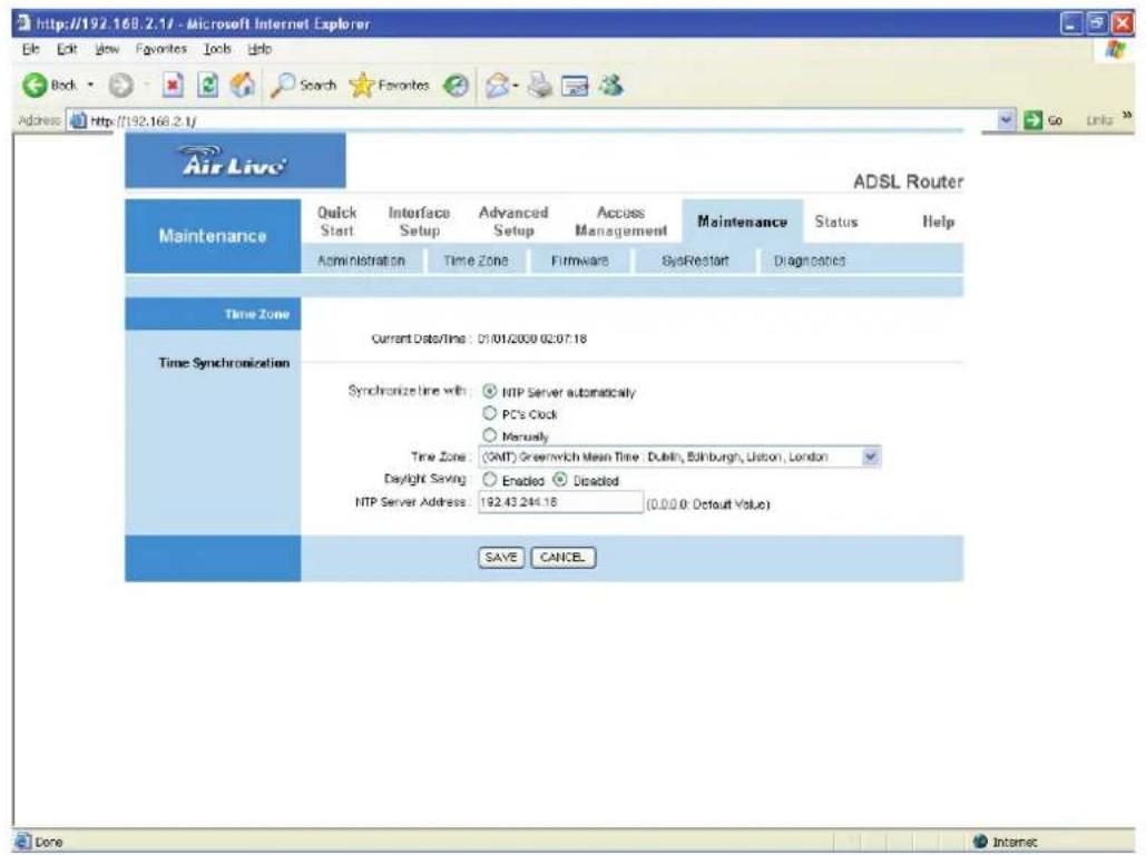
Parameter Description
Current Date/Time Show the current date/time of the router.
Synchronize time with NTP Server Automatically – Set the time by following with a NTP Server.
PC's Clock – Set the time the same as your computer.
Manually – Set the time manually.
Time Zone Select the time zone of the country you are currently in.
The router will set its time based on your selection.
Daylight Saving Select this option if it is in daylight savings time.
NTP Server Address Enter the IP Address of your time server.
5.5.3. Firmware
If you have new firmware for some features update, please upgrade firmware of the router here.
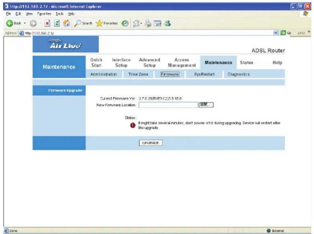
Parameter Description
New Firmware Type in the location of the new firmware or click "Browse" Location to find it.
Browse Click "Browse" to find the new firmware.
Upgrade Click "Upgrade" to begin the upgrade process. After the router is restarted, the process is completed. It might take several minutes, don't power off the router during upgrading.
5.5.4. System Restart
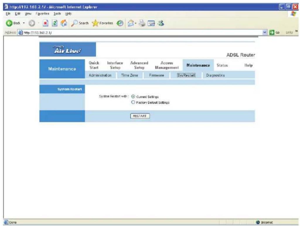
In this page, you can restart your router or restore to factory defaults. If you wish to restart the router using the factory default settings, select "Factory Default Settings" to reset to factory defaults. You can also click the "Reset" button in the rear panel of the router over 5 seconds to reset default settings.
5.5.5. Diagnostics
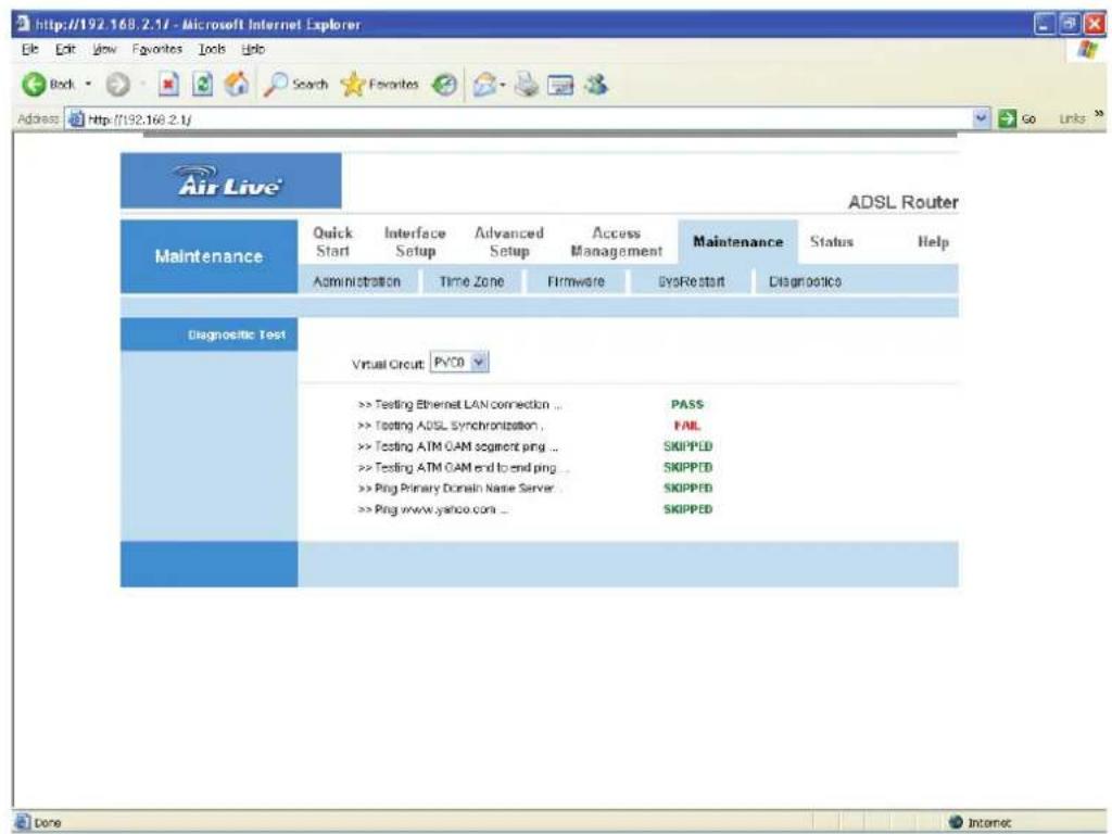
This page allows you to diagnose the connectivity of the LAN and WAN network.
5.6. Status
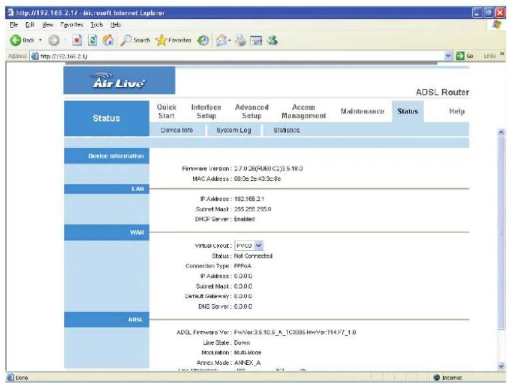
5.6.1. Device Info
In this page, you can know the device information including firmware, MAC Address, LAN and WAN settings and also the ADSL line status.
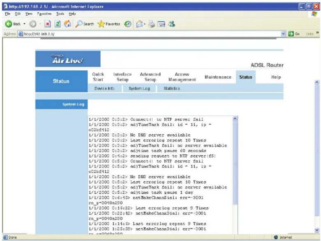
5.6.2. System Log
Display system logs accumulated up to the present time. You can also save the logs for future reviewing.
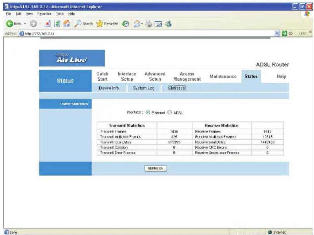
5.6.3. Statistics
Show the statistics of transmit and receive packets on the LAN port and the ADSL line.
6. Troubleshooting
- The LAN LED on the front panel does not light up.
| STEPS | CORRECTIVE ACTION |
| 1 Check the | Ethernet cable connections between your ADSL2+Router and the computer or hub. |
| 2 Check for faulty Ethernet cables. | |
| 3 Make sure | your computer's Ethernet card is working properly. |
| 4 If these steps fail to correct the problem, contact your local distributor for assistance. | |
- The ADSL LED on the front panel does not light up.
| STEPS | CORRECTIVE ACTION |
| 1 Check the | telephone wire and connections between ADSL2+Router DSL port and the wall jack. |
| 2 Make sure | that the telephone company has checked your phone line and set it up for DSL service. |
| 3 Reset your | ADSL line to reinitialize your link to the DSLAM. |
| 4 If these steps fail to correct the problem, contact your local distributor for assistance. | |
- I cannot access the web management.
| STEPS | CORRECTIVE ACTION |
| 1 Make sure | you are using the correct IP address of ADSL2+Router. Check the IP address of ADSL2+ Router. |
| 2 Your computer and ADSL2+ Router's IP addresses must be on the same subnet for LAN access. | |
| 3 If you changed ADSL2+ Router's LAN IP address, then enter the new one as the URL. | |
The following procedures will help you to check the current IP Address setting of your computer. You can compare if your computer and router's IP Addresses are in the same subnet.
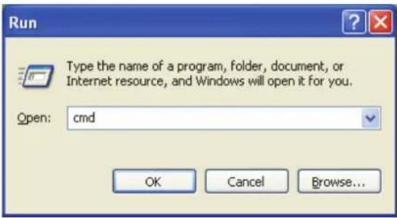
Step 1: Click "Start" and select "Run".
Step 2: Type in "cmd" and click "OK".
Step 3: Type ipconfig /all and click enter.
![C:\WINDOWS\system32\cmd.exe Microsoft Windows XP [Version 5.1.2600] (C) Copyright 1985-2001 Microsoft Corp. C:\Documents and Settings\Test>ipconfig/all Windows IP Configuration Host Name . . . . . . . . . . . . . : test-b6663a0cd4 Primary Dns Suffix . . . . . . . . . . : Node Type . . . . . . . . . . . . : Unknown IP Routing Enabled. . . . . . . . . : No WINS Proxy Enabled. . . . . . . . : No Ethernet adapter Local Area Connection: Connection-specific DNS Suffix . : Description . . . . . . . . . . : Intel(R) PRO/100 VE Network Connecti on Physical Address. . . . . . . . . : 00-00-E2-82-C3-AD Dhcp Enabled. . . . . . . . : No IP Address. . . . . . . . . : 192.168.2.111 Subnet Mask . . . . . . . . : 255.255.255.0 Default Gateway . . . . . . : C:\Documents and Settings\Test>](/content/2026/05/843551/images/e1a53200abee629414e87b9c2e87c38516a538051e1e752509ef5a0626bd886a.jpg)
- Your PC's IP address is 192.168.2.111.
• The PC's Subnet Mask is 255.255.255.0. -
Your PC's MAC Address is the one entitled Physical Address (00-00-E2-82-C3-AD).
-
I forget my login username and/or password.
| STEPS | CORRECTIVE ACTION |
| 1 If you have | changed the password and have now forgotten it, you will need to upload the default configuration file. This will erase all custom configurations and restore all of the factory defaults including the password. |
| 2 Press the R | Reset button for five seconds, and then release it.When the LAN LED begins to blink, the defaults have been restored. |
| 3 The default | username is “admin”. The default password is “1234”.The Password and Username fields are case-sensitive. Make sure that you enter the correct password and username using the proper casing. |
| 4 It is highly | recommended to change the default username and password. Make sure you store the username and password in a save place. |
- I cannot access the Web Management of the router after activating the ACL function.
| STEPS | CORRECTIVE ACTION |
| 1 When ACL | is activated, you have to set the ACL rule for allowing some users to use some services. Check if you have set the rules. If not, all the users are forbidden using any of service from LAN or WAN. |
| 2 If you cannot access the Web Management of the router, please press the Reset button over 5 seconds to restore to defaults. | |
| 3 After the router is restarting, log in the router with the default IP Address 192.168.2.1. | |
- Initialization of the ADSL connection failed.
| STEPS | CORRECTIVE ACTION |
| 1 Check the | cable connections between the ADSL port and the wall jack. The ADSL LED on the rear panel of the router should be on. |
| 2 Check VPI, | VCI, type of encapsulation and type of multiplexing settings are the same as what you collected from your ISP. |
| 3 Restart the | router. If you still have problems, you may need to verify your VPI, VCI, type of encapsulation and type of multiplexing settings with the ISP. |
- I cannot get a WAN IP address from the ISP.
| STEPS | CORRECTIVE ACTION |
| 1 The ISP provides the WAN IP address after authenticating you. Authentication may be through the user name and password, the MAC address or the host name. | |
| 2 The username and password apply to PPPoE and PPoA encapsulation only. Make sure that you have entered the correct Service Type, User Name and Password (be sure to use the correct casing). | |
- Internet connection disconnects.
| STEPS | CORRECTIVE ACTION |
| 1 Check the schedule rules. | |
| 2 If you use PPPoA or PPPoE encapsulation, check the idle time-out setting. | |
| 3 | Contact your ISP. |
7. Glossary
10Base-T
It is an Ethernet standard for Local Area Network (LAN). 10Base-T uses a twisted pair cable with maximum length of 100 meters.
AAL
ATM Adaptation Layer that defines the rules governing segmentation and reassembly of data into cells. Different AAL types are suited to different traffic classes.
ADSL
Asymmetric Digital Subscriber Line, as its name showing, is an asymmetrical data transmission technology with high traffic rate downstream and low traffic rate upstream. ADSL technology satisfies the bandwidth requirement of applications, which demand “asymmetric” traffic, such as web surfing, file download and Video-on-demand (VOD).
ATM
Asynchronous Transfer Mode is a layer 2 protocol supporting high-speed asynchronous data with advanced traffic management and quality of service features.
bps
Bits per second, a standard measurement of digital transmission speeds.
Bridge
A device that connects two or more physical networks and forwards packets between them. Bridges can usually be made to filter packets, that is, to forward only certain traffic. Related devices are: repeaters which simply forward electrical signals from one cable to the other and full-fledged routers which make routing decisions based on several criteria.
CPE
Customer Premises Equipment, such as ADSL router, USB modem.
Default Gateway (Router)
Every non-router IP device needs to configure a default gateway's IP address. When the device sends out an IP packet, if the destination is not on the same network, the device has to send the packet to its default gateway, which will then send it out towards the destination.
DHCP
Dynamic Host Configuration Protocol, this protocol automatically gives every computer on your home network an IP address.
DNS Server IP Address
DNS stands for Domain Name System, which allows Internet servers to have a domain name (such as www.Broadbandrouter.com) and one or more IP addresses (such as 192.34.45.8). A DNS server keeps a database of Internet servers and their respective domain names and IP addresses, so that when a domain name is requested (as in typing "Broadbandrouter.com" into your Internet browser), the user is sent to the proper IP address. The DNS server IP address used by the computers on your home network is the location of the DNS server your ISP has assigned to you.
DSL
Digital Line Subscriber (DSL) technology provides high-speed access over twisted copper pair for connection to the Internet, LAN interfaces, and to broadband services such as video-on-demand, distance learning, and video conferencing.
Ethernet
It is a standard for computer networks. Ethernet networks are connected by special cables and hubs or switches, and move data around at up to 10/100 million bits per second (Mbps).
FTP
File Transfer Protocol. The Internet protocol (and program) used to transfer files between hosts.
Idle Timeout
Idle Timeout is designed so that after there is no traffic to the Internet for a pre-configured amount of time, the connection will automatically be disconnected.
ISP
Internet Service Provider is a business that provides connectivity to the Internet for individuals and other businesses or organizations.
ISP Gateway Address
The ISP Gateway Address is an IP address for the Internet router located at the ISP's office.
LAN
Local Area Network is a group of computers and devices connected together in a relatively small area (such as a house or an office). Your home network is considered a LAN.
MAC Address
MAC stands for Media Access Control. A MAC address is the hardware address of a device connected to a network. The MAC address is a unique identifier for a device with an Ethernet interface. It is comprised of two parts: 3 bytes of data that corresponds to the Manufacturer ID (unique for each manufacturer), plus 3 bytes that are often used as the product's serial number.
MTU
Maximum Transmission Unit
NAT
Network Address Translator is defined by RFC 1631. Enable a LAN network to use one set of IP address for internal traffic. A NAT box located where the LAN meets the Internet provides the necessary IP address translation. This helps provide a sort of firewall and allow for a wider address range to be used internally without danger of conflict. Using the router's NAT capability, you can access the Internet from any computer on your home network without having to purchase more IP addresses from your ISP.
Port
Network Clients (LAN PC) uses port numbers to distinguish one network application/protocol over another. Below is a list of common applications and protocol/port numbers:
| Application | Protocol | Port Number |
| Telnet | TCP | 23 |
| FTP | TCP | 21 |
| SMTP | TCP | 25 |
| POP3 | TCP | 110 |
| H.323 | TCP | 1720 |
| SNMP | UCP | 161 |
| SNMP Trap UDP 162 | ||
| HTTP | TCP | 80 |
| PPTP | TCP | 1723 |
| PC Anywhere TCP 5631 | ||
| PC Anywhere UDP 5632 | ||
PPP
PPP is the Point-to-Point-Protocol. The successor to SLIP, PPP provides router-to-router and host-to-network connections over both synchronous and asynchronous circuits.
PPPoA (RFC 2364)
The Point-to-Point Protocol (PPP) provides a standard method for transporting multi-protocol data grams over point-to-point links. This document describes the use of ATM Adaptation Layer 5 (AAL5) for framing PPP encapsulated packets.
PPPoE (RFC 2516)
This document describes how to build PPP sessions and encapsulate PPP packets over Ethernet. PPP over Ethernet (PPPoE) provides the ability to connect a network of hosts over a simple bridging access device to a remote Access Concentrator.
Protocol
A protocol is a set of rules for interaction agreed upon between multiple parties so that when they interface with each other based on such a protocol, the interpretation of their behavior is well defined and can be made objectively, without confusion or misunderstanding.
PVC
Permanent Virtual Circuit, connection-oriented permanent leased line circuit between end-stations on a network over a separate ATM circuit.
RFC
Request for Comments. The document series, begun in 1969, which describes the Internet suite of protocols and related experiments. Not all RFCs describe Internet standards, but all Internet standards are written up as RFCs.
RFC 1483
Multi-protocol encapsulation over AAL-5. Two encapsulation methods for carrying network interconnect traffic over ATM AAL-5. The first method allows multiplexing of multiple protocols over a single ATM virtual circuit. The protocol of a carried PDU is identified by prefixing the PDU by an IEEE 802.2 Logical Link Control (LLC) header. This method is in the following called "LLC Encapsulation". The second method does higher-layer protocol multiplexing implicitly by ATM Virtual Circuits (VCs). It is in the following called "VC Based Multiplexing".
Router
A system responsible for making decisions about which of several paths network (or Internet) traffic will follow. To do this, it uses a routing protocol to gain information about the network and algorithms to choose the best route based on several criteria known as "routing metrics.
Subnet Mask
A subnet mask, which may be a part of the TCP/IP information provided by your ISP, is a set of four numbers (e.g. 255.255.255.0) configured like an IP address. It is used to create IP address numbers used only within a particular network (as opposed to valid IP address numbers recognized by the Internet, which must be assigned by InterNIC).
TCP/IP, UDP
Transmission Control Protocol/Internet Protocol (TCP/IP) and Unreliable Datagram Protocol (UDP). TCP/IP is the standard protocol for data transmission over the Internet. Both TCP and UDP are transport layer protocol. TCP performs proper error detection and error recovery, and thus is reliable. UDP on the other hand is not reliable. They both run on top of the IP (Internet Protocol), a network layer protocol.
TELNET
It is the virtual terminal protocol in the Internet suite of protocols. Allows users of one host to log into a remote host and act as normal terminal users of that host.
VCI
Virtual Circuit Identifier is part of the ATM cell header. A VCI is a tag indicating the channel over which a cell will travel. The VCI of a cell can be changed as it moves between switches via Signaling.
VPI
Virtual Path Identifier is part of the ATM cell header. A VPI is a pipe for a number of Virtual Circuits.
WAN
Wide Area Network is a network that connects computers located in geographically separate areas (e.g. different buildings, cities, countries). The Internet is a wide area network.
Web-based management Graphical User Interface (GUI)
Many devices support a graphical user interface that is based on the web browser. This means the user can use the familiar Netscape or Microsoft Internet Explorer to Control/configure or monitor the device being managed.
- User's Guide
- Copyright
- FCC Interference Statement
- CE Declaration of Conformity
- Contents
- INTRODUCTION .... 1
- HARDWARE INSTALLATION ......6
- SETUP WIZARD......7
- IP ADDRESS SETTING ....13
- WEB MANAGEMENT CONFIGURATION......21
- MAINTENANCE....59
- STATUS....64
- TROUBLESHOOTING 67
- GLOSSARY....71
- Introduction
- Features
- ADSL2/2+ Compliance
- Support 802.11g Wireless Access Point
- Router
- Access Management
- Minimum Requirements
- Package Content
- Hardware Placement
- Rear Panel
- 1) Antenna Connector
- 2) Reset
- 3) Power Jack
- 4) Local Area Network (LAN)
- 5) ADSL
- Front LEDs
- Hardware Installation
- Step 1. Connect the ADSL Line
- Step 2. Connect the router to your LAN network
- Step 3. Connect the Power Adapter to the Router
- Step4: Check the ADSL LED on the Router
- Setup Wizard
- IP Address Setting
- Windows XP
- Windows 2000
- Windows 95/98/Me
- Windows NT
- Web Management Configuration
- Quick Start (Section 5.1)
- Interface Setup (Section 5.2)
- Advanced Setup (Section 5.3)
- Access Management (Section 5.4)
- Maintenance (Section 5.5)
- Status (Section 5.6)
- Help
- Quick Start
- Step 1: Set your new password
- Step 2: Choose your tome zone
- Step 3: Set your Internet connection
- Step 4: Input the data supplied by your ISP
- Step 5: Re-start your ADSL router
- Interface Setup
- Internet
- Parameter Description
- - Encapsulation
- • Dynamic IP Address/Static IP Address/PPPoE/PPPoA/Bridge Mode
- LAN
- - Router Local IP
- • DHCP
- Wireless
- - Wireless LAN
- • WEP/WPA-PSK/WPA2-PSK
- - Advanced Setting
- - Wireless MAC Address Filter
- Advanced Setup
- Firewall
- Routing
- Best IP Mask Gateway IP Metric Device Use Edit Drop
- - Routing Table List
- NAT
- NAT
- DMZ
- Virtual Server
- ADSL
- Access Management
- ACL
- IP Filter
- - IP Filter Set Editing
- • IP Filter Rule Editing
- - IP Filter Listing
- SNMP
- UPnP
- DDNS
- Maintenance
- Administrator
- Time Zone
- Firmware
- System Restart
- Diagnostics
- Status
- Device Info
- System Log
- Statistics
- Troubleshooting
- Glossary
- 10Base-T
- AAL
- ADSL
- ATM
- bps
- Bridge
- CPE
- Default Gateway (Router)
- DHCP
- DNS Server IP Address
- DSL
- Ethernet
- FTP
- Idle Timeout
- ISP
- ISP Gateway Address
- LAN
- MAC Address
- MTU
- NAT
- Port
- PPP
- PPPoA (RFC 2364)
- PPPoE (RFC 2516)
- Protocol
- PVC
- RFC
- RFC 1483
- Subnet Mask
- TCP/IP, UDP
- TELNET
- VCI
- VPI
- WAN
- Web-based management Graphical User Interface (GUI)
Brand : AIRLIVE
Model : WT-2000ARM
Category : Router