
LIE1014A - Switch Black Box - Free user manual and instructions
Find the device manual for free LIE1014A Black Box in PDF.


| Product Type | Industrial Managed Gigabit PoE+ Ethernet Switch |
| Model | LIE1014A |
| Ports | (8) 10/100/1000BASE-T(X) PoE+ ports, (4) 100/1000BASE SFP slots |
| PoE Standard | IEEE 802.3af/at, up to 30 W per port, total budget 240 W |
| Power Input | 12–58 VDC (PoE model: 46–58 VDC), dual redundant terminals |
| Power Consumption (without PoE) | 14 W |
| Dimensions (H x W x D) | 6.1 x 3.0 x 5 in (15.4 x 7.7 x 12.8 cm) |
| Weight | 3.1 lb (1.4 kg) |
| Operating Temperature | -40 to +167°F (-40 to +75°C) |
| Ingress Protection | IP30 |
| Switching Capacity | L2 wire-speed, non-blocking, store-and-forward |
| MAC Address Table | 8K entries |
| Jumbo Frame Support | 9K bytes |
| VLAN Support | Port-based VLAN, IEEE 802.1Q tag-based VLAN, double tagging (Q-in-Q), up to 1024 VLANs |
| QoS | 8 priority queues per port, scheduling: SPQ, WRR, SP-WRR |
| Network Redundancy | Ring protection (<20 ms failover), STP/RSTP/MSTP, dual ring, dual homing |
| Security | ACL (MAC, IP, L4 port, ToS), 802.1x authentication, IP source guard, port security |
| Management | CLI (console/telnet), Web GUI, SNMP v1/v2c, HTTPS, SSH, RADIUS client |
| Indicators | Power, alarm, PoE, link/activity, speed LEDs |
| Certifications | CE, FCC Class A, EN 50121-4, CSA C22.2, IEC61000-4-2/3/4/5/6 |
Frequently Asked Questions - LIE1014A Black Box
User questions about LIE1014A Black Box
0 question about this device. Answer the ones you know or ask your own.
Ask a new question about this device
Download the instructions for your Switch in PDF format for free! Find your manual LIE1014A - Black Box and take your electronic device back in hand. On this page are published all the documents necessary for the use of your device. LIE1014A by Black Box.
USER MANUAL LIE1014A Black Box
Industrial Managed Gigabit Ethernet Switch
User Manual
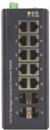
natural_image
Front view of a network switch device with multiple Ethernet ports (no visible text or labels)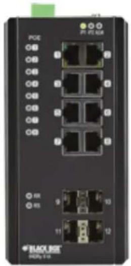
natural_image
Front view of a black network switch device with multiple Ethernet ports and I/O ports (no visible text or labels)Trademarks Used in this Manual
Black Box and the Double Diamond logo are registered trademarks of BB Technologies, Inc.
Any other trademarks mentioned in this manual are acknowledged to be the property of the trademark owners.
We're here to help! If you have any questions about your application or our products, contact Black Box Tech Support at 877-877-2269 or go to blackbox.com and click on "Talk to Black Box."
You'll be live with one of our technical experts in less than 60 seconds.
Federal Communications Commission and Industry Canada Radio Frequency Interference Statements
This equipment generates, uses, and can radiate radio-frequency energy, and if not installed and used properly, that is, in strict accordance with the manufacturer's instructions, may cause interference to radio communication. It has been tested and found to comply with the limits for a Class A computing device in accordance with the specifications in Subpart B of Part 15 of FCC rules, which are designed to provide reasonable protection against such interference when the equipment is operated in a commercial environment. Operation of this equipment in a residential area is likely to cause interference, in which case the user at his own expense will be required to take whatever measures may be necessary to correct the interference.
Changes or modifications not expressly approved by the party responsible for compliance could void the user's authority to operate the equipment.
This digital apparatus does not exceed the Class A limits for radio noise emission from digital apparatus set out in the Radio Interference Regulation of Industry Canada.
Black Box Network Services shall not be liable for damages of any kind, including, but not limited to, punitive, consequential or cost of cover damages, resulting from any errors in the product information or specifications set forth in this document and Black Box Network Services may revise this document at any time without notice.
Black Box Network Services shall not be liable for damages of any kind, including, but not limited to, punitive, consequential or cost of cover damages, resulting from any errors in the product information or specifications set forth in this document and Black Box Network Services may revise this document at any time without notice.
Quick Study: Condensed Explanation of Terms Used in this Manual
Terms related to network access rights:
ACL (Access Control List): List of Access Control Entries (ACEs). Each ACE specifies the access rights of a device.
QoS (Quality of Service): Method to allocate priority of bandwidth per device on a network.
WRR (Weighted Round-Robin): Network scheduling method that gives each packet its own packet queue.
SP-WRR (Strict Priority Weighted Round-Robin): Packets identified by QoS class and priority queues. Helps to determine which packets are transmitted first on a network.
ToS (Type of Service): Specifies a data packet's priority for transmission over a network.
Terms related to location:
MAC (Media Access Control) Address: A computer's unique hardware identification number.
VLAN (Virtual Local Area Network: A network with flexible logical connections (vs. physical connections) between LANs. Commonly used with IP cameras, VoIP phones, and wireless (Wi-Fi, Bluetooth) applications.
Dual Ring: A network redundant technology where nodes are connected using two rings with four branches. Use for small networks that are not frequently reconfigured.
IP (internet Protocol) Address: Number that identifies a host or or network interface location.
Terms related to data security:
802.1x Authentication: Ensures integrity of the data being transferred on a network.
Dual Homing: Provides a redundant network interface for added security.
Terms related to OSI layers:
Open Systems Interconnection (OSI): Lists the communication functions of a computing system without considering internal structure and technology.
IGMP (Internet Group Management Protocol): Used to discover and manage multicast groups. IGMP is part of the Network layer in the OSI communication model.
Terms related to data traffic:
L4: In an L4 switch, data traffic is prioritized by application, using a hardware-switching technology that can distinguish between HTTP, FTP, or VoIP.
POE (Power Over Ethernet): Technology that enables both data and power signals to be transmitted over one cable.
RSTP (Rapid Spanning Tree Protocol): Prevents loops on an Ethernet network. Protects your network from "hanging" caused by endless data loops.
Multicast Group: Used for streaming media applications on the internet and private networks.
Ring Protection: A ring is a network with two paths between any two nodes on the network. Ring protection ensures that one of the two paths are not broken if the other path fails.
SNMP (Simple Network Management Protocol): Internet standard protocol used to collect and organize information from managed devices on an IP network.
Table of Contents
- Specifications 8
- Overview 11
2.1 Introduction....11
2.2 Features....11
2.3 What's Included....12
2.4 Additional Items You May Need 12
2.5 Hardware Description 12
2.5.1 LIG1014A 12
2.5.2 LIE1014A 13
- Connecting to Your Industrial Managed Gigabit Ethernet Switch.... 14
3.1 Connecting to Your Switch via a Serial Console 14
3.2 Connecting to the Switch via Telnet 17
3.3 Connecting to the Switch via a Web Browser 18
- Switch Functions.... 19
4.1 VLAN Application Guide 19
4.1.1 Explanation of VLAN (Virtual LAN) 19
4.1.2 Example 1: Default VLAN Settings.... 19
4.1.3 Example 2: Port-Based VLANs 20
4.1.4 Example 3: IEEE 802.1Q Tagging....22
4.2 Security Application Guide 24
4.2.1 Explanation of ACL (Access Control List)....24
4.2.2 Case 1: ACL for MAC Addresses 24
4.2.3 Case 2: ACL for IP Addresses....35
4.2.4 Case 3: ACL for L4 Port 35
4.2.5 Case 4: ACL for ToS....35
4.3 Ring Protection Application Guide....36
4.3.1 Explanation of Ring Protection....36
4.3.2 Configuration (Console) 37
4.3.3 Configuration (Web GUI) 38
4.3.4 Dual Ring 43
4.3.5 Dual Homing....46
4.4 Ring Version 2 Feature....47
4.4.1 Explanation of Ring Version 2 47
4.4.2 Group 1: Supports Ring-Master and Ring-Slave Option....48
4.4.3 Group 2: Supports Ring, Coupling, and Dual-Homing Configurations....48
4.4.4 Group 3: Supports Chain and Balancing-Chain Configurations 49
4.5 Configuring Ringv2 50
4.5.1 Configuration (Console)....50
4.5.2 Configuration (Web UI) 50
4.5.3 Disable RSTP on All Ring Ports 51
4.5.4 Ring Master 52
4.5.5 Ring Slave 52
4.5.6 Coupling Primary 53
4.5.7 Coupling Backup 53
4.5.8 Dual-Homing 54
4.5.9 Chain(Member)....54
4.5.10 Chain (Head) 55
4.5.11 Chain (Tail) 55
4.5.12 Balance Chain (Central Block) 56
4.5.13 Balance Chain (Terminal) 56
4.6 QoS Application Guide 57
4.6.1 Explanation of QoS 57
4.6.2 SP/SPWRR/WRR 57
4.6.3 Example 1: SPQ Without Shaping (Default Profile) 57
4.6.4 Example 2: SPQ With Shaping....60
4.6.5 Example 3: WRR....63
4.6.6 Example 4: SP-WRR 67
4.7 IGMP Application Guide 74
4.7.1 Explanation of IGMP 74
4.7.2 Configuring VLC on an IGMP Server....78
4.7.3 Configuring VLC on an IGMP Client 81
4.8 801.1x Authentication Guide 83
4.8.1 Explanation of 802.1x Authentication ....83
4.8.2 802.1x Timer in Industrial Managed Gigabit Ethernet Switch....83
4.8.3 Configuration in RADIUS Server 83
- Hardware Quick Setup Guide 87
5.1 What's Included....87
5.2 Mounting the Switch on a DIN Rail 87
5.3 Mounting the Switch on a Wall....88
5.4 Ethernet Interface 88
5.4.1 RJ-45 88
5.4.2 Fiber SFP 89
5.5 Connecting the Power Terminal Block....89
5.6 Alarm Relay and Ground 90
5.7 Console Connection 91
5.8 Connect and Login to Managed Switch 91
5.9 CLI Initialization and Configuration....91
5.10 Indicators....92
- Specifications
| Ethernet | |
| Operating Mode Store and forward, L2 wire-speed/non-blocking switching engine | |
| MAC Addresses 8K | |
| Jumbo Frames 9K Bytes | |
| Copper RJ-45 Ports | |
| Speed 10/100/1000 Mbps | |
| MDI/MDIX Auto-Crossover Supports straight-through or cross-pinned cables | |
| Auto-negotiating 10/100/1000 Mbps speed auto-negotiation; Full- and half-duplex | |
| Ethernet isolation 1500 VRMS 1 minute | |
| SFP (Pluggable) Ports | |
| Port Types Supported | SFP (pluggable) Ports 100/1000BASE SFP slot Supports 100/1000BASE-T SFP transceiver |
| Fiber Port Connector LC typically for fiber (depends on module) | |
| Optimal Fiber Cable | 50- or 62.5/125-μm for multimode (MM);8- or 9/125-μm for single mode (SM) |
| Network Redundancy | |
| Fast Failover Protection Rings Link loss recovery < 20 ms,Single and multiple rings supported | |
| Spanning Tree Protocol | IEEE 802.1D STP, IEEE 802.1w RSTP, IEEE 802.1s MSTP |
| Port Trunk with LACP | Static trunk or Dynamic via LACP (Link Aggregation Control Protocol) |
| Bridge, VLANs, and Protocols | |
| Flow Control | IEEE 802.3x (Full Duplex) and Back-Pressure (Half Duplex) |
| VLAN Types | Port-based VLANs,IEEE 802.1Q tag-based VLANs,IEEE 802.1ad Double Tagging (Q in Q) |
| Multicast Protocols | IGMP v1, v2,IGMP snooping and querying,Immediate leave and leave proxy,Throttling and filtering |
| LLDP | IEEE 802.1ab Link layer Discovery Protocol (LLDP) |
| Traffic Management and QoS | |
| Priority | IEEE 802.1p QoS |
| Number of Queues per Port | 8 |
| Scheduling Schemes | SPQ, WRR |
| Traffic Shaper | Port-based shaping |
| Security | |
| Port Security | IP and MAC-based access control,IEEE 802.1x authentication Network Access Control |
| Power | |
| Power Input | Redundant Input Terminals |
| Input Voltage Range | LIG1014A, LIE1014A (without PoE): 12–58 VDCLIE1014A (with PoE): 46–58 VDC |
| Maximum Power Consumption | LIG1014A: 17 W,LIE1014A (without PoE): 14 W,LIE1014A (with PoE): 265 W |
| Power (continued) | |
| Reverse Power Protection Yes | |
| Total PoE Output Power Budget 240 watts | |
| PoE PSE Port Output Power Management | Scheduling; power control; PoE PD power consumption monitoring |
| Transient Protection >15,000 watts peak | |
| Indicators (LEDs) | |
| Power Status LED Indicates power input status | |
| Ethernet Port LED Link and Speed | |
| Management | |
| User Management Interfaces CLI (command-line interface),Web-based Management,SNMP v1, v2c,Telnet (5 sessions) | |
| Management Security HTTPS, SSH, | Radius Client for Management |
| Upgrade and Restore Configuration Import/Export,Firmware Upgrade | |
| Diagnostic Syslog, | Per VLAN mirroring,SFP with DDM (Digital Diagnostic Monitoring) |
| MIBs RMON 1,2,3,9; Q-Bridge MIB,, | RFC 1213 MIB-II, RFC 4188 Bridge MIB |
| DHCP Client, Server, Relay, Snooping, Option 82 | |
| NTP/SNTP Yes | |
| Environment | |
| Operating Temperature Range -40 to +167°F (-40 to +75°C) (cold startup at -40°C) | |
| Storage Temperature Range | -40 to +185°F (-40 to +85°C) |
| Humidity (non-condensing) | 5 to 95% RH |
| Approvals | |
| Certification Compliance | CE/FCC; EN-50121-4 |
| Electrical Safety | CSA C22, EN61010-1, CE |
| EMC | FCC Part 15, CISPR 22 (EN55022) Class A,IEC61000-4-2, -3, -4, -5, -6 |
| MTBF >25 years | |
| RoHS and WEEE | RoHS (Pb free) and WEEE compliant |
| Mechanical | |
| Connectors | LIG1014A: (10) RJ-45 10/100/1000BASE-T(X), (4) 100/1000BASE SFP;LIE1014A: (8) RJ-45 10/100/1000BASE-T(X), (4) 100/1000BASE SFP |
| Ingress Protection IP30 | |
| Installation Options | DIN-Rail mounting, Wallmounting |
| Dimensions | LIG1014A: 6"H x 2.4"W x 4.3"D (15.4 x 6 x 10.9 cm);LIE1014A: 6.1"H x 3.0"W x 5"D (15.4 x 7.7 x 12.8 cm) |
| Weight | LIG1014A: 2.4 lb. (1.1 kg);LIE1014A: 3.1 lb. (1.4 kg) |
| System Statistics | |
| Function Name System Maximum Value | |
| VLAN ID 4096 | |
| VLAN Limitation 1024 | |
| Privilege Level of User 15 | |
| RMON Statistic Entry 65535 | |
| RMON Alarm Entry 65 | |
| RMON Event Entry 65535 | |
| IPMC Profile 64 | |
| IPMC Rule / Address Entry 128 | |
| ACE 256 | |
| ICMP Type / Code 255 | |
| RADIUS Server 5 | |
| TACACS+ Server 5 | |
| MAC-based VLAN Entry | 256 |
| IP subnet-based VLAN Entry | 128 |
| Protocol-based VLAN Group | 125 |
| Voice VLAN OUI | 16 |
| QCE | 256 |
| IP Interface | 8 |
| IP Route | 32 |
| Security Access Management | 16 |
| MVR VLAN | 4 |
| MAC Learning table address | 8k |
| IGMP Group | 256 |
2. Overview
2.1 Introduction
The Industrial Managed Gigabit Ethernet Switch is a high-quality switch that operates in a wide temperature range and an extended power input range. The switch features advanced VLAN and QoS features. It's ideal for harsh environments and mission-critical applications.
Table 2-1. Available models
| Component LIG1014A LIE1014A (PoE) | ||
| Total Gigabit Ethernet Ports | 14 12 | |
| 10/100/1000BASE-T(X) 10 8 | ||
| 100/1000BASE SFP 4 4 |
Power over Ethernet
The LIE1014A switch supports Power over Ethernet compliant to the IEEE 802.3af and IEEE 802.3at standard on all copper ports. The switch can power standard PoE PD devices with up to 30 watts per port along with the Ethernet data on standard Ethernet cabling.
Multi-rate SFP slots
Multi-rate SFP slots enable you to mix-and-match 100-Mbps and 1-Gbps SFP Modules for either multi- or single-mode as needed. If requirements change, just replace the SFP module and protect your switch investment.
Power
The switches are powered from 12- to 58-VDC. The PoE model (LIE1014A) needs 48 VDC for 802.3af and a minimum of 53 VDC for 802.3at.
Extended temperature range
All models are tested and released for operating temperatures from -40^ up to +75^ Celsius. They passed shock, vibration, and freefall test and comply with the IEC600068-2-6, -27 and -32 standards.
Management
The switches offer powerful features including Layer 3 routing and management with all advanced filter and multicast algorithms needed today to easily prioritize, partition, and organize a reliable high-speed network.
2.2 Features
- Provide (8) or (10) 10/100/1000 ports plus (4) multi-rate SFP slots.
- Extended temperature range: -40^ to +75^ .
• L2 wire speed switching.
• 12- to 58-VDC dual input, reverse polarity. - IP30 industrial design.
- DIN-rail mountable.
- Shock, vibration and freefall test to IEC60068-2-6, -27, -32.
• EMC approval acc. to IEC61000-4-2, -3, -4, -5, -6 (Level 3).
- LIE1014A model uses Power over Ethernet Plus to deliver 30 watts power per port to remote PD devices.
2.3 What's Included
Your package should contain the following items. If anything is missing or damaged, contact Black Box Technical Support at 877-877-2269 or info@blackbox.com.
LIG1014A:
- Industrial Managed Gigabit Ethernet Switch with (10) 10/100/1000BASE-T(X) ports and (4) 100/1000BASE SFP ports
- Printed Quick Start Guide
LIE1014A:
- Industrial Managed Gigabit PoE Ethernet Switch with (8) 10/100/1000BASE-T(X) ports and (4) 100/1000BASE SFP ports.
- Printed Quick Start Guide
2.4 Additional Items You Will Need
- SFP modules
Table 2-2 lists compatible SFP modules (ordered separately). These modules install in the SFP slots on the managed switch.
Table 2-2. Compatible SFP modules.
| Part Number Description |
| LFP411 SFP/1250 Extended Diagnostics, LC multimode, 850 nm, 550 m |
| LFP412 SFP/1250 Extended Diagnostics, LC multimode, 1310 nm, 2 km |
| LFP413 SFP/1250 Extended Diagnostics, LC single-mode, 1310 nm, 10 km |
| LFP414 SFP/1250 Extended Diagnostics, LC single-mode, 1310 nm, 40 km |
| LFP401 SFP/155 Extended Diagnostics, LC multimode, 850 nm, 2 km |
| LFP403 SFP/155 Extended Diagnostics, LC single-mode, 1310 nm, 30 km |
| LFP404 SFP/155 Extended Diagnostics, LC single-mode, 1310 nm, 60 km |
| LFP402 SFP/155 Extended Diagnostics, LC multimode, 1310 nm, 2 km |
| LFP418 SFP/1250 Extended Diagnostics, LC single-mode, 1550 nm, 80 km |
| LFP420 Simplex SFP/1250, Extended Diagnostics, single-mode, 1550 nm TX, 1310 nm RX |
2.5 Hardware Description LIG1014A
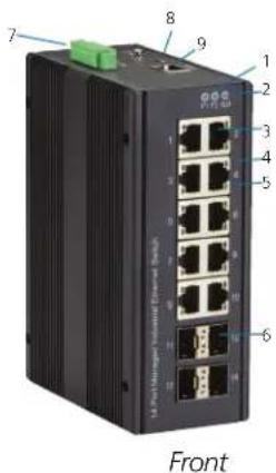
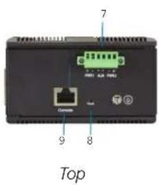
Figure 2-1. LIG1014A, Front Panel and Top Panel.
LIE1014A
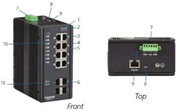
Figure 2-2. LIE1014A, Front Panel and Top Panel.
Table 2-3. Components of the LIG1014A and LIE1014A.
| Number in Figures2-1 and 2-2 | Component | LIG1014A | LIE1014A (PoE) | Function |
| 1 | (2) Power LEDs | (1) P1, (1) P2 | (1) P1, (1) P2 | Links to power |
| 2 (1) Alarm LED (1) ALM (1) ALM | ||||
| 3 | Gigabit Ethernet Copper Ports | (10) RJ-45 | (8) RJ-45 | |
| 4 | Link LEDs | (10) | (8) | |
| 5 | Speed LEDs | (10) | (8) | |
| 6 Gigabit Ethernet SFP ports (4) SFP slots (4) SFP slots | ||||
| 7 Power Input (Dual) via 6-pinTerminal Block | (1) Power | |||
| 8 (1) Reset Button | (1) Reset | |||
| 9 | Console (RS-232)RJ-45 | (1) RJ-45 | (1) RJ-45 | Links to console |
| 10 | POE LED (LIE1014A only) | POE port status | ||
| 11 | RR/RS LEDs | Device info/status | ||
3. Connecting to Your Industrial Managed Gigabit Ethernet Switch
You can connect to your switch in three ways:
-
Via a serial console.
-
Via a Telnet console.
-
Via a Web browser.
NOTE: You can't connect to a serial console and a Telnet console at the same time. You can connect to the Web console and a serial or Telnet console at the same time, but we do NOT recommend this.
3.1 Connecting to Your Switch via a Serial Console
You will need:
- Switch
- An RJ-45 female to DB9 or DB25 female cable (not included)
- Serial PC or terminal (not included) with terminal emulation software installed
An example below is shown using the PuTTY terminal emulation program. PuTTY is an open-source SSH and Telnet client.
STEP 1: Physically connect the switch to the serial console.
Using the RJ-45 female to DB9 or DB25 female cable (not included), connect the DB9 or DB25 serial console port to the switch.
STEP 2: Check to see if a terminal emulation program is installed on the PC. If it is not, install it now.
Launch PuTTy. Select Terminal from the menu on the left side of the screen. Select the key sequences, application keypad settings, and extra keyboard features. Next, click Open.
![PuTTY Configuration Category: Session Logging Terminal Keyboard Bell Features Window Appearance Behaviour Translation Selection Colours Connection Data Proxy Telnet Rlogin SSH Serial Options controlling the effects of keys Change the sequences sent by: The Backspace key Control-H Control-? (127) The Home and End keys Standard oxt The Function keys and keypad ESC[n~ Linux Xterm R6 VT400 VT100+ SCO] Application keypad settings: Initial state of cursor keys: Normal Application Initial state of numeric keypad: Normal Application NetHack Enable extra keyboard features: AltGr acts as Compose key Control-Alt is different from AltGr About Open Cancel](/content/2026/05/843115/images/e37e4a04ce7f607533ef6beb78cb91ee2df59f96eab62ca2df079f27e6c3216d.jpg)
Figure 3-1. Select terminal screen.
STEP 3: Once you go back to the session, select the Connection type as Serial. Fill in the Serial line and Speed fields with COM port and speed to be used. Click Only on clean exit, then click Open.
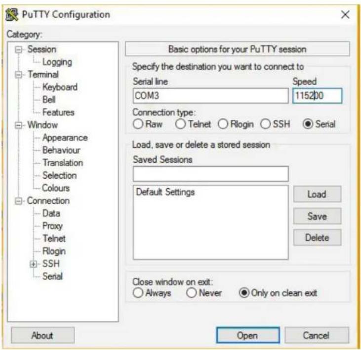
Figure 3-2. PuTTY options screen.
STEP 4: Select Connection —> Serial from the left-hand column. The screen below appears.
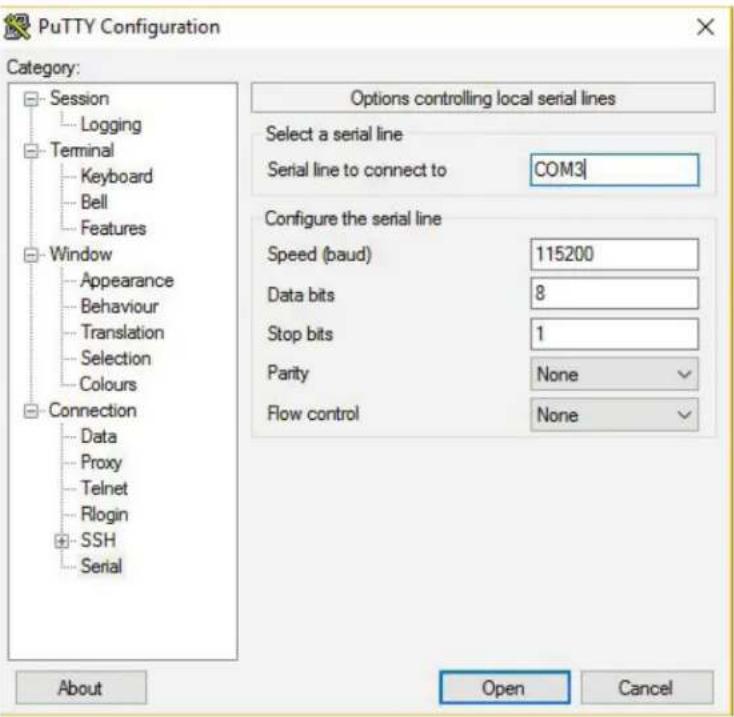
Figure 3-3. Local serial lines connections options.
Enter these values in the screen:
- Serial line: the COM port you are using
• Speed (baud) rate: 115,200 bps - Data bits: 8
- Stop bits: 1
- Parity: None
- Flow control: None
Once you are done, click Open and then press Enter.
STEP 5: The serial console prompts you to log in. Enter the default username and password:
Username: admin
Password: (none)
NOTE: The password is left blank. To login, simply type admin in the Username field, then press Enter. The cursor will jump to the Password field. Press Enter again.
STEP 6: The CLI prompt of the Switch's serial console appears. Use the CLI Guide to find your way around the CLI.
Table 3-1. Keyboard functions.
| Key Function |
| Up, down, right, or left arrow keys, Tab Move the cursor on-screen |
| Enter Press this key to select options |
| Space Press to toggle between settings. |
| Esc Go to the previous menus |
3.2 Connecting to the Switch via Telnet
NOTE: The PC host and the switch must be on the same logical subnet. See the table below.
Table 3-2. Default IP addresses of the switch and PC host.
| IP Address Subnet Mask |
| Switch 192.0.2.1 255.255.255 |
| PC Host 192.0.2.xxx 255.255.255.0 |
NOTE: The switch's default IP address is 192.0.2.1
STEP 1: Using a straight-through or crossover cable, connect the switch's RJ-45 Ethernet port to your Ethernet LAN or to your PC's Ethernet port.
NOTE: It does not matter if the Ethernet cable is pinned straight-through or cross-pinned; the switch supports Auto MDI-X.
STEP 2: From the Windows Run menu, click Start—>Run.
STEP 3: Type in the Switch's default IP address: 192.0.2.1
STEP 4: A telnet prompt appears. Select the terminal type.
STEP 5: Log in using the switch's default username and password:
Username: admin
Password: (none)
NOTE: The password is left blank. To login, simply type admin in the Username field, then press Enter. The cursor will jump to the Password field. Press Enter again.
The main menu of the switch's Telnet console appears.
3.3 Connecting to the Switch via a Web Browser
NOTE: The PC host and the switch must be on the same logical subnet. See the table below.
Table 3-3. Default IP addresses of the switch and PC host.
| IP Address Subnet Mask |
| Switch 192.0.2.1 255.255.255 |
| PC Host 192.0.2.xxx 255.255.255.0 |
STEP 1: Using a straight-through or crossover cable, connect the switch's RJ-45 Ethernet port to your Ethernet LAN or to your PC's Ethernet port.
STEP 2: Open the switch's web console. Enter the switch's IP address in the Address or URL field. The default IP address is 192.0.2.1.
STEP 3: The web console login screen will appear. Enter the username and password.
Username: admin
Password: (none)
NOTE: The password is left blank. To login, simply type admin in the Username field, then press Enter. The cursor will jump to the Password field. Press Enter again. If you don't want to create a password, just press Enter.
4. Switch Functions
4.1 VLAN Application Guide
4.1.1 Explanation of VLAN (Virtual LAN)
You can increase the efficiency of your network by dividing it into local segments (VLANs) instead of physical segments. A VLAN (Virtual LAN) is a group of devices that you can place anywhere on a network without being restricted by physical connections (a limitation of a traditional physical network). VLANs enable you to segment your network into groups, for example, departmental, hierarchial, or usage groups. A VLAN segments a network to make it more flexible than a physical network. VLANs make it easy to relocate devices on networks (no physical cable moves). VLANs also give your network extra security and help control network traffic.
The Industrial Managed Gigabit Ethernet Switch supports up to 2048 VLANs. Ports are grouped into broadcast domains by assigning them to the same VLAN. Frames received on a VLAN can only be forwarded within that VLAN, and multicast frames and unknown unicast frames are flooded only to ports in the same VLAN.
4.1.2 Example 1: Default VLAN Settings
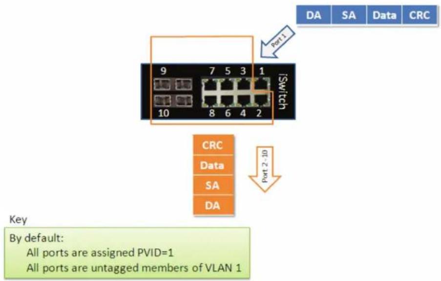
Each port in the LIG1014A/LIE1014A Switch has a configurable default VLAN number, known as its PVID. This places all ports on the same VLAN initially, although each port PVID is configurable to any VLAN number between 1 and 4094.
The default configuration settings for the switch have all ports set as untagged members of VLAN 1 with all ports configured as PVID=1. In default configuration example shown in the following figure, all incoming packets are assigned to VLAN 1 by the default port VLAN identifier (PVID=1).
flowchart
graph TD
    A["Switch"] --> B["Port 1"]
    B --> C["Port 2-10"]
    C --> D["Data"]
    D --> E["SA"]
    E --> F["DA"]
    G["Port 1"] --> H["9"]
    G --> I["7"]
    G --> J["5"]
    G --> K["3"]
    G --> L["1"]
    M["Port 2"] --> N["10"]
Figure 4-1. Default VLAN Settings.
4.1.3 Example 2: Port-based VLANs
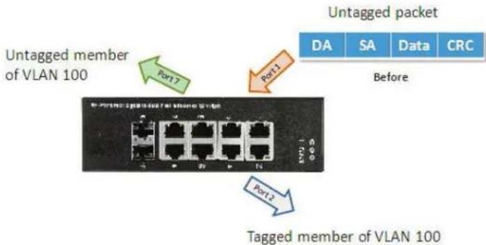
When the LIG1014/LIE1014A receives an untagged VLAN packet, it will add a VLAN tag to the frame according to the PVID setting on a port. As shown in the following figure, the untagged packet is marked (tagged) as it leaves the LIG1014/LIE1014A through Port 2, which is configured as a tagged member of VLAN100. The untagged packet remains unchanged as it leaves the LIG1014/LIE1014A through Port 7, which is configured as an untagged member of VLAN100.
flowchart
graph TD
    A["Untagged member of VLAN 100"] --> B["Port1"]
    A --> C["Port2"]
    B --> D["Untagged packet"]
    C --> E["Tagged member of VLAN 100"]
Figure 4-2. Port-Based VLAN.
Configuration:
STEP 1: Go to Configuration -> VLANs -> Port VLAN configuration and configure PVID 100 on Port 1, Port 2, and Port 7.
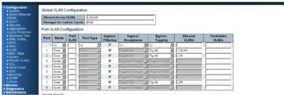
Figure 4-3. Configure PVID.
STEP 2. Select Configuration -> VLAN -> Static VLAN. Create a VLAN with VLAN ID 100. Enter a VLAN name in the Name field.
STEP 3. Assign a VLAN tag setting to or remove it from a port by toggling the checkbox under an individual port number. The tag settings determine if packets that are transmitted from the port tagged or untagged with the VLAN ID. The possible tag settings are:
- Tag All: Specifies that the egress packet is tagged for the port.
- Untag port vlan: Specifies that the egress packet is untagged for the port.
- Untag All: Specifies that all frames, whether classified to the Port VLAN or not, are transmitted without a tag.
Here we set tagged VLAN100 on Port 1 and Port 2, untagged VLAN100 on Port 7.
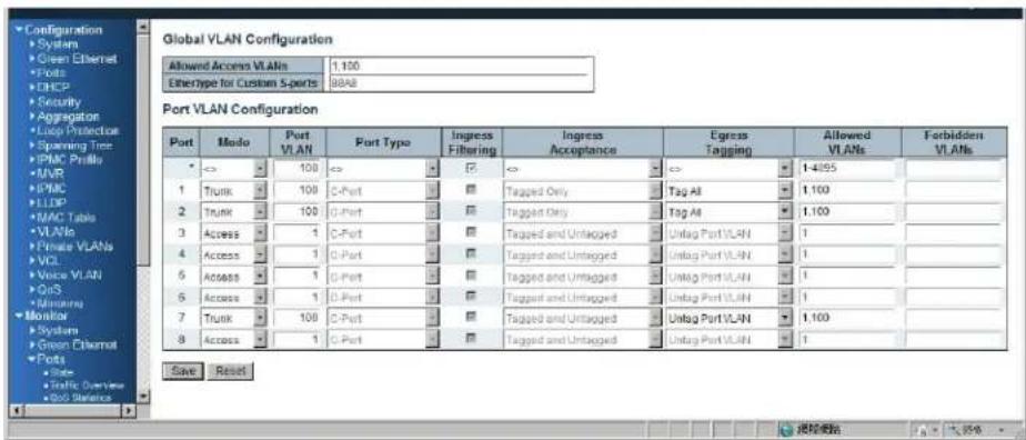
Figure 4-4. Set tagged and untagged VLAN on ports.
STEP 4: Transmit untagged unicast packets from Port 1 to Port 2 and Port 7. The LIG1014/LIE1014A should tag a packet with VID 100. The packet has access to Port 2 and Port 7. The outgoing packet is stripped of its tag to leave Port 7 as an untagged packet. For Port 2, the outgoing packet leaves as a tagged packet with VID 100.
STEP 5: Transmit untagged unicast packets from Port 2 to Port 1 and Port 7. The LIG1014/LIE1014A should tag a packet with VID 100. The packet has access to Port 1 and Port 7. The outgoing packet is stripped of its tag to leave Port 7 as an untagged packet. For Port 1, the outgoing packet leaves as a tagged packet with VID 100.
STEP 6: Transmit untagged unicast packets from Port 7 to Port 1 and Port 2. The LIG1014/LIE1014A should tag a packet with VID 100. The packet has access to Port 1 and Port 2. For Port 1 and Port 2, the outgoing packet leaves as a tagged packet with VID 100.
STEP 7: Repeat step 4 using broadcast and multicast packets.
CLI Commands
vlan 1
vlan 100
interface GigabitEthernet 1/1
switchport access vlan 100
switchport trunk native vlan 100
switchport trunk allowed vlan 1,100
switchport trunk vlan tag native
switchport mode trunk
exit
interface GigabitEthernet 1/2
switchport access vlan 100
switchport trunk native vlan 100
switchport trunk allowed vlan 1,100
switchport trunk vlan tag native
switchport mode trunk
exit
interface GigabitEthernet 1/7
switchport access vlan 100
switchport trunk native vlan 100
switchport trunk allowed vlan 1,100
switchport mode trunk
exit
4.1.4 Example 3: IEEE 802.1Q Tagging
LIG1014/LIE1014A is able to construct a layer-2 broadcast domain by identifying a VLAN ID specified by IEEE 802.1Q. It forwards a frame between bridge ports assigned to the same VLAN ID and can set multiple VLANs on each bridge port.
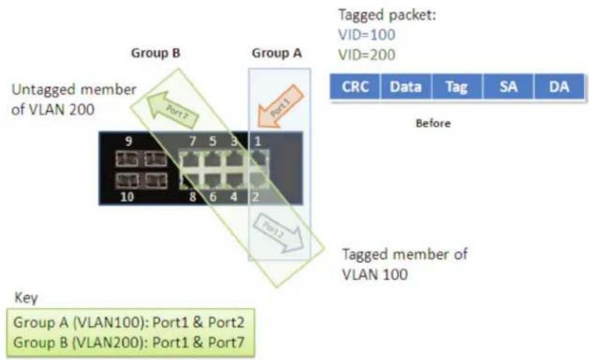
In the following figure, the tagged incoming packets are assigned directly to VLAN 100 and VLAN 200 because of the tag assignment in the packet. Port 2 is configured as a tagged member of VLAN 100, and Port 7 is configured as an untagged member of VLAN 200. Hosts in the same VLAN communicate with each other as if they were in a LAN. However, hosts in different VLANs cannot communicate with each other directly.
flowchart
graph TD
    A["Untagged member of VLAN 200"] --> B["Group A"]
    B --> C["Group B"]
    C --> D["Tagged packet: VID=100, VID=200"]
    D --> E["CRC"]
    D --> F["Data"]
    D --> G["Tag"]
    D --> H["SA"]
    D --> I["DA"]
    J["Key: Group A (VLAN100): Port1 & Port2\nGroup B (VLAN200): Port1 & Port7"] --> K["Port1"]
    K --> L["Port2"]
    L --> M["Port3"]
    M --> N["Port4"]
    N --> O["Port5"]
    O --> P["Port6"]
    P --> Q["Port7"]
    R["Before"] --> S["Tagged member of VLAN 100"]
Figure 4-5. IEEE 801.1Q Tagging.
In this case:
- The hosts from Group A can communicate with each other.
- The hosts from Group B can communicate with each other.
- The hosts of Group A and Group B can't communicate with each other.
- Both the Group A and Group B can go to the Internet through the LIE1014A/LIG1014A.
Configuration:
STEP 1: Go to Configuration -> VLANs -> Port VLAN configuration page and specify the VLAN membership as follows:
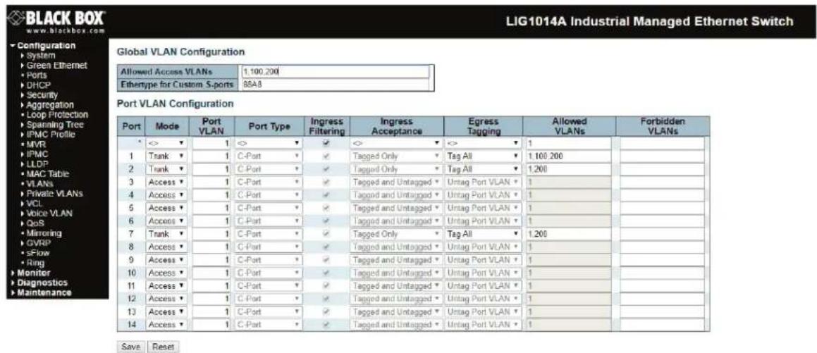
Figure 4-6. Specify VLAN membership.
STEP 2: Transmit unicast packets with VLAN tag 100 from Port 1 to Port 2 and Port 7. The LIG1014/LIE1014A should tag a packet with VID 100. The packet only has access to Port 2. For Port 2, the outgoing packet leaves as a tagged packet with VID 100.
STEP 3: Transmit unicast packets with VLAN tag 200 from Port 1 to Port 2 and Port 7. The LIG1014/LIE1014A should tag a packet with VID 200. The packet only has access to Port 7. The outgoing packet on Port 7 is stripped of its tag as an untagged packet.
STEP 4: Transmit unicast packets with VLAN tag 100 from Port 2 to Port 1 and Port 7. The LIG1014/LIE1014A should tag a packet with VID 100. The packet only has access to Port 1. For Port 1, the outgoing packet leaves as a tagged packet with VID 100.
STEP 5: Transmit unicast packets with VLAN tag 200 from Port 7 to Port 1 and Port 2. The LIG1014/LIE1014A should tag a packet with VID 200. The packet only has access to Port 1. The outgoing packet on Port 1 will leave as a tagged packet with VID 200.
STEP 6: Repeat the above steps using broadcast and multicast packets.
CLI Command:
vlan 1
vlan 100
interface GigabitEthernet 1/1
switchport access vlan 100
switchport trunk native vlan 100
switchport trunk allowed vlan 1,100
switchport trunk vlan tag native
switchport mode trunk
exit
interface GigabitEthernet 1/2
switchport access vlan 100
switchport trunk native vlan 100
switchport trunk allowed vlan 1,100
switchport trunk vlan tag native
switchport mode trunk
exit
interface GigabitEthernet 1/7
switchport access vlan 100
switchport trunk native vlan 100
switchport trunk allowed vlan 1,100
switchport mode trunk
exit
4.2 Security Application Guide
4.2.1 Explanation of ACL (Access Control List)
Access Control List (ACL) is a traffic filter for ingress and egress packets. It checks each Ethernet packet and filters/forwards it to its destination. ACL settings might include the packet's source or destination IP address, packet's source or destination MAC address, IP protocols, and more. ACL examines these values to permit or access a packet.
The LIG1014A/LIE1014A's ACL function supports access control security for MAC address, IP address, Layer 4 Port, and Type of Service. Each has five actions: Deny, Permit, Queue Mapping, CoS Marking, and Copy Frame. You can set the default ACL rule to Permit or Deny. For details about the switch's ACL function, see the following table.
Table 4-1. Default ACL Rule Actions.
| Deny | Permit | Queue | Mapping | CoS | Marking | |
| Permit | (a) | (b) | (c) | (d) | (e) | |
| Deny | (f) | (g) | (h) | (i) | (j) |
Below is a description of the ACL rules listed in Table 4-1 that the switch uses:
(a): Permit all frames, but deny frames set in ACL entry.
(b): Permit all frames.
(c): Permit all frames, and map queues of the transmitting frames.
(d): Permit all frames, and change the CoS value of the transmitting frames.
(e): Permit all frames, and copy a frame set in ACL entry to a defined GE port.
(f): Deny all frames.
(g): Deny all frames, but permit frames set in ACL entry.
(h): Deny all frames.
(i): Deny all frames.
(j): Deny all frames, but to copy frame which set in ACL entry to a defined GE port.
4.2.2 Case 1: ACL for MAC address
The MAC address ACL filters source MAC address, destination MAC address, or both. When it filters both MAC addresses, packets for both rules take effect. In other words, the switch does not filter MAC addresses if it only complies with the rule for one of the two MAC addresses.
To filter only one directional MAC address, set the other MAC address to all zeros. The switch can also filter VLAN and Ether type. If you don't want to filter VLAN and Ether type, set them both to all zeros.
- Case 1: Permit all frames, but deny frames set in ACL entry.
Set the default ACL Rule of GE port to "Permit", then bind a suitable profile with "deny" for ACL. The GE port can pass through all packets except for the ACL entry of the bound profile.
Filter One MAC Address, but Deny Filtering for One VLAN
To filter one directional MAC address with one VLAN denied filtering, follow the steps listed next:
STEP 1: Create a new ACL Profile. (Profile Name: DenySomeMac)
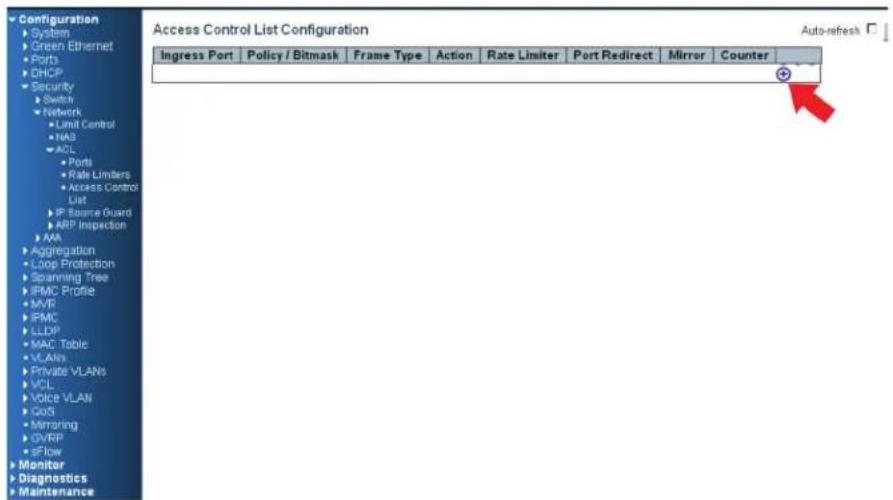
Figure 4-7. Create new ACL profile screen.
STEP 2: Create a new ACL Entry rule under this ACL profile. (Deny MAC: 11 and VLAN: 4)
STEP 3: Bind this ACL profile to a GE port. (Port 4)
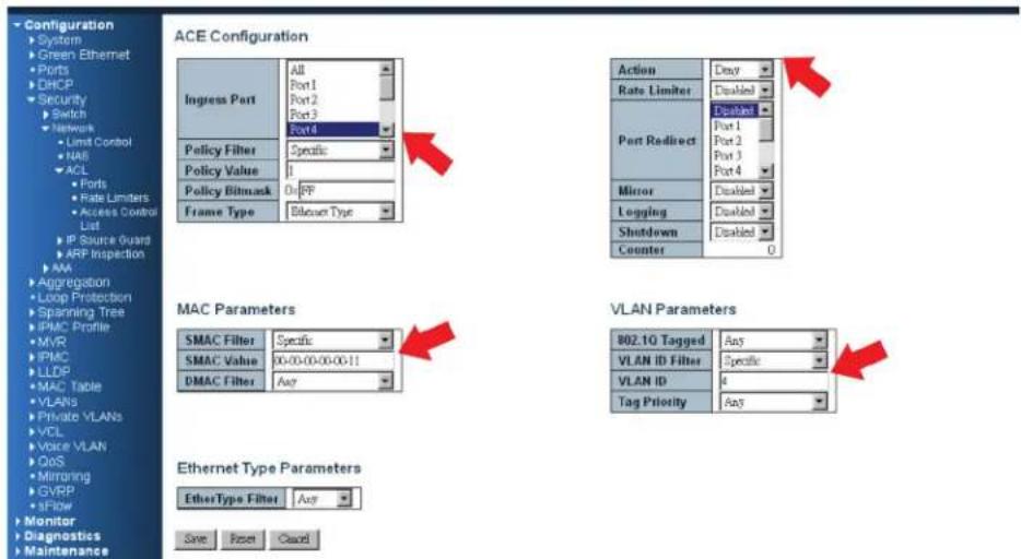
Figure 4-8. Bind the ACL profile to a Gigabit Ethernet port screen.
STEP 4: Send frames between Port 3 and Port 4, and see the test result.
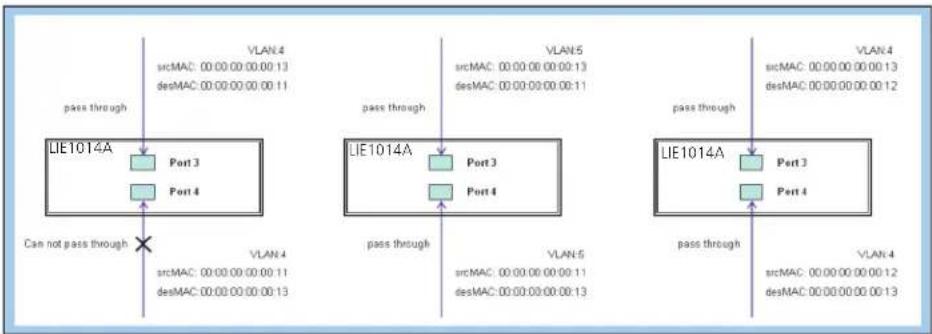
flowchart
graph TD
    subgraph LIE1014A
        A["Port 3"] -->|pass through| B["VLAN 4"]
        C["Port 4"] -->|pass through| D["VLAN 5"]
        E["Port 3"] -->|pass through| F["VLAN 4"]
        G["Port 4"] -->|pass through| H["VLAN 5"]
        I["Port 3"] -->|pass through| J["VLAN 4"]
        K["Port 4"] -->|pass through| L["VLAN 5"]
        M["Port 3"] --> N["VLAN 4"]
        O["Port 4"] --> P["VLAN 5"]
        Q["Port 3"] --> R["VLAN 4"]
        S["Port 4"] --> T["VLAN 5"]
        U["Port 3"] --> V["VLAN 4"]
        W["Port 4"] --> X["VLAN 5"]
        Y["Port 3"] --> Z["VLAN 4"]
        AA["Port 4"] --> AB["VLAN 5"]
        AC["Port 3"] --> AD["VLAN 4"]
        AE["Port 4"] --> AF["VLAN 5"]
        AG["Port 3"] --> AH["VLAN 4"]
        AI["Port 4"] --> AJ["VLAN 5"]
        AK["Port 3"] --> AL["VLAN 4"]
        AM["Port 4"] --> AN["VLAN 5"]
        AO["Port 3"] --> AP["VLAN 4"]
        AQ["Port 4"] --> AR["VLAN 5"]
        AS["Port 3"] --> AT["VLAN 4"]
        AU["Port 4"] --> AV["VLAN 5"]
        AW["Port 3"] --> AX["VLAN 4"]
        AY["Port 3"] --> AZ["VLAN 5"]
    end
    style LIE1014A fill:#f9f,stroke:#333
    style A fill:#ccf,stroke:#333
    style B fill:#cfc,stroke:#333
    style C fill:#cfc,stroke:#333
    style D fill:#cfc,stroke:#333
    style E fill:#cfc,stroke:#333
    style F fill:#cfc,stroke:#333
    style G fill:#cfc,stroke:#333
    style H fill:#cfc,stroke:#333
    style I fill:#cfc,stroke:#333
    style AJ fill:#cfc,stroke:#333
    style AK fill:#cfc,stroke:#333
    style AL fill:#cfc,stroke:#333
    style AM fill:#cfc,stroke:#333
    style AN fill:#cfc,stroke:#333
    style AO fill:#cfc,stroke:#333
Figure 4-9. Test result: frames sent between Port 3 and Port 4.
CLI Commands:
access-list ace 1 ingress interface GigabitEthernet 1/4 policy 1 vid 4
frametype etype smac 00-00-00-00-00-11 action deny
exit
interface GigabitEthernet 1/3
switchport trunk allowed vlan 4,5
switchport trunk vlan tag native
!
interface GigabitEthernet 1/4
switchport trunk allowed vlan 4,5
switchport trunk vlan tag nativevlan 4
exit
Filter Two Directional MAC Addresses, with Filtering Denied to All VLANs
Follow these steps:
STEP 1: Create a new ACL Profile. (Profile Name: DenySomeMac)
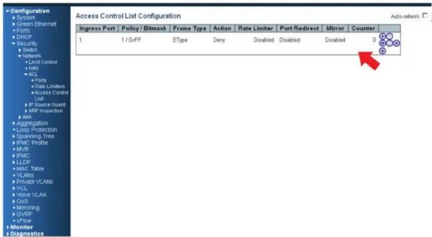
Figure 4-10. Create new ACL profile.
STEP 2: Create a new ACL Entry rule under this ACL profile. (Deny SrcMAC: 13 and DesMAC: 11)
STEP 3: Bind this ACL profile to a GE port. (Port 3)
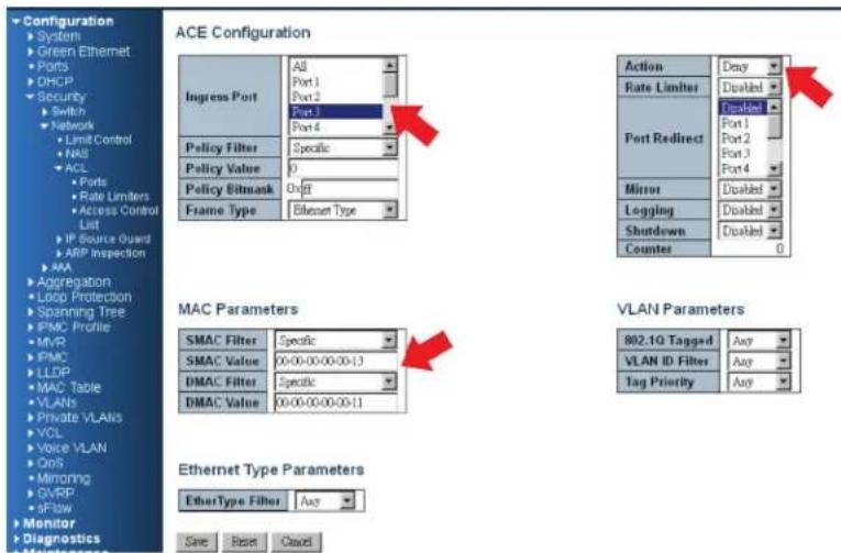
Figure 4-11. Bind ACL profile to a Gigabit Ethernet port.
STEP 4: Send frames between Port 3 and Port 4, and see the test result.
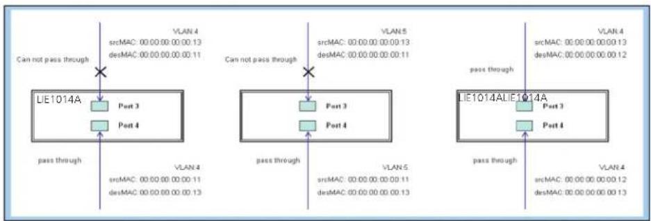
flowchart
graph TD
    A["LE1014A"] -->|Pass through| B["Port 3"]
    A -->|Pass through| C["Port 4"]
    D["LE1014ALIE1014A"] -->|Pass through| E["Port 3"]
    D -->|Pass through| F["Port 4"]
    G["VLAN 4"] --> H["srcMAC: 00.00.00.00.00.13"]
    G --> I["desMAC: 00.00.00.00.00.11"]
    J["VLAN 5"] --> K["srcMAC: 00.00.00.00.00.13"]
    J --> L["desMAC: 00.00.00.00.00.11"]
    M["VLAN 4"] --> N["srcMAC: 00.00.00.00.00.13"]
    M --> O["desMAC: 00.00.00.00.00.12"]
    P["VLAN 4"] --> Q["srcMAC: 00.00.00.00.00.13"]
    P --> R["desMAC: 00.00.00.00.00.13"]
Figure 4-12.
CLI Commands:
access-list ace 2 ingress interface GigabitEthernet 1/3 policy 0 frametype etype smac
00-00-00-00-00-13 dmac 00-00-00-00-00-11 action deny
exit
interface GigabitEthernet 1/3
switchport trunk allowed vlan 4,5
switchport trunk vlan tag native
!
interface GigabitEthernet 1/4
switchport trunk allowed vlan 4,5
switchport trunk vlan tag nativevlan 4
exit
- Case 1: (b) Permit all frames.
In this case, ACL function is disabled. All frames will pass through.
- Case 1: (c) Permit all frames, and map queues of the transmitting frames.
Set the default Gigabit Ethernet port ACL Rule to "Permit", then bind a suitable profile with "Queue Mapping" for some ACL functions. Map queues 0–7 of the frame received from this port.
- Case 1: (d) Permit all frames, and change the CoS value of the transmitting frames.
Set the default Gigabit Ethernet port ACL Rule as "Permit", then bind a suitable profile with "CoS Marking" action for some ACL functions. Change the CoS values of the VLAN frames received from this port.
To set one directional MAC address with CoS Marking:
STEP 1: Create a new ACL Profile. (Profile Name: CoSMarkingTest)
STEP 2: Create a new ACL Entry rule under this ACL profile.
(Filter SrcMAC: 11 and VLAN ID: 4 frame to CoS: 2)
STEP 3: Bind this ACL profile to a GE port. (Port 4)
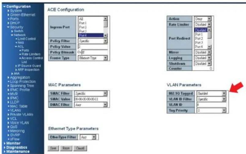
Figure 4-13.
STEP 4: Send frames between Port 3 and Port 4, and see the test result.
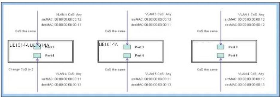
flowchart
graph TD
    A["CoS the same"] --> B["LIE1014A"]
    B --> C["Change CoS to 2"]
    D["VLAN 4 CoS Any srcMAC: 00.00.00.00.00.13, desMAC: 00.00.00.00.00.11"] --> E["Part 3"]
    E --> F["CoS the same"]
    G["VLAN 5 CoS Any srcMAC: 00.00.00.00.00.13, desMAC: 00.00.00.00.00.11"] --> H["Part 3"]
    H --> I["CoS the same"]
    J["VLAN 4 CoS Any srcMAC: 00.00.00.00.00.13, desMAC: 00.00.00.00.00.12"] --> K["Part 3"]
    K --> L["CoS the same"]
    M["VLAN 4 CoS Any srcMAC: 00.00.00.00.00.12, desMAC: 00.00.00.00.00.13"] --> N["Part 4"]
    N --> O["CoS the same"]
Figure 4-14.
CLI Commands:
access-list ace 1 next 2 ingress interface GigabitEthernet 1/4 policy 1 vid 4 frametype etype smac 00-00-00-00-00-11 action deny exit
interface GigabitEthernet 1/3| switchport trunk allowed vlan 4,5 switchport trunk vlan tag native
interface GigabitEthernet 1/4 switchport trunk allowed vlan 4,5 switchport trunk vlan tag native exit
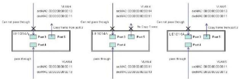
- Case 1: (e) Permit all frames, and copy a frame set in ACL entry to a defined GE port.
Set the default ACL Rule of GE port to "Permit", then bind a suitable profile with "Copy Frame" for a mirror analyzer used. The system will copy frames from a binding GE Port to analyzer port.
To set two directional MAC addresses with Copy Frame:
STEP 1: Create a new ACL Profile. (Profile Name: CopyFrameTest)
STEP 2: Create a new ACL Entry rule under this ACL profile. (SrcMAC: 13 and DesMAC: 11)
STEP 3: Set the analyzer port to enable and mirror the analyzer port.
STEP 4: Bind this ACL profile to a GE port. (Port 3)
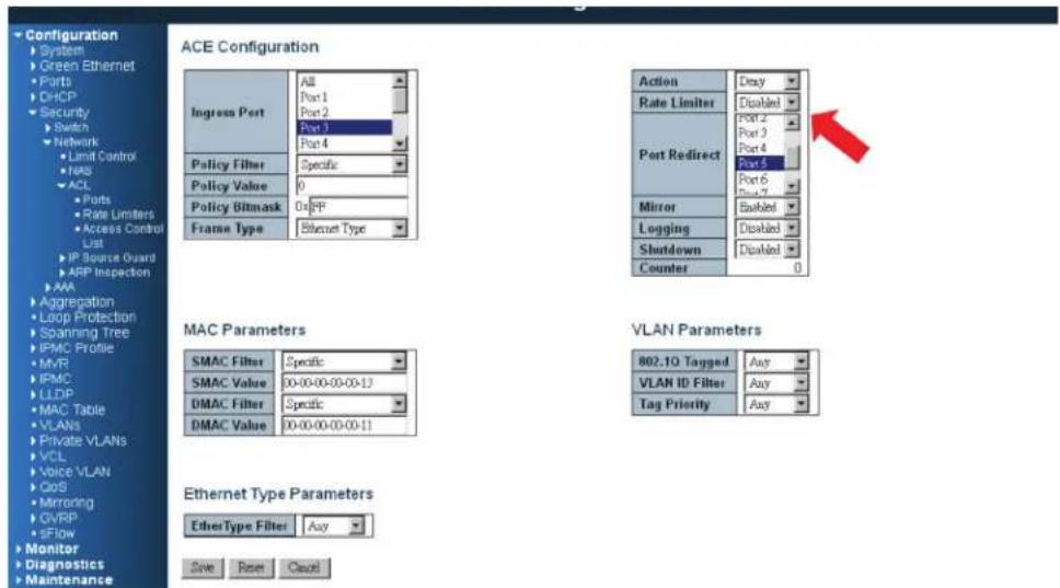
Figure 4-15.
STEP 5: Send frames between Port 3 and Port 4, and see the test result.

flowchart
graph TD
    subgraph VLAN_4
        A["Port 3"] -->|Pass through| B["Port 4"]
        C["Port 5"] -->|Copy frame from port 3| D["Port 4"]
        E["VLAN 4 srcMAC: 00.00.00.00.00.13"]
        F["desMAC: 00.00.00.00.00.11"] --> D
    end
    subgraph VLAN_4
        G["Port 3"] -->|No Copy Frame| H["Port 4"]
        I["Port 5"] -->|No Copy Frame| H
        J["VLAN 4 srcMAC: 00.00.00.00.00.14"]
        K["desMAC: 00.00.00.00.00.11"] --> H
    end
    subgraph VLAN_5
        L["Port 3"] -->|Copy frame from port 3| M["Port 4"]
        N["Port 5"] -->|Copy frame from port 3| M
        O["VLAN 5 srcMAC: 00.00.00.00.00.13"]
        P["desMAC: 00.00.00.00.00.11"] --> M
    end
Figure 4-16.
CLI Commands:
access-list ace 2 next 3 ingress interface GigabitEthernet 1/3 policy 0 frametype etype smac 00-00-00-00-00-13 dmac 00-00-00-00-00-11 action deny mirror redirect interface GigabitEthernet 1/5
exit
interface GigabitEthernet 1/3
switchport trunk allowed vlan 4,5
switchport trunk vlan tag native
!
interface GigabitEthernet 1/4
switchport trunk allowed vlan 4,5
switchport trunk vlan tag native
exit
- Case 1: (f) Deny all frames.
All frames will not pass through.
- Case 1: (g) Deny all frames, but permit frames set in ACL entry.
Set the default ACL Rule of a GE port as "Deny", then bind a suitable profile with "Permit" for ACL. The GE port cannot pass through any packets except the ACL entry of the bound profile.
To set one directional MAC address with one VLAN filtered:
STEP 1: Create a new ACL Profile. (Profile Name: AllowSomeMac)
STEP 2: Create a new ACL Entry rule under this ACL profile. (Allow MAC: 11 and VLAN: 4)
STEP 3: Bind this ACL profile to a GE port. (Port 4)
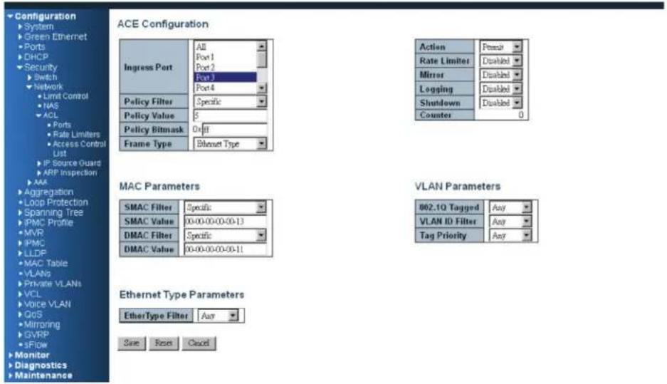
Figure 4-17.
STEP 4: Send frames between Port 3 and Port 4, and see the test result.
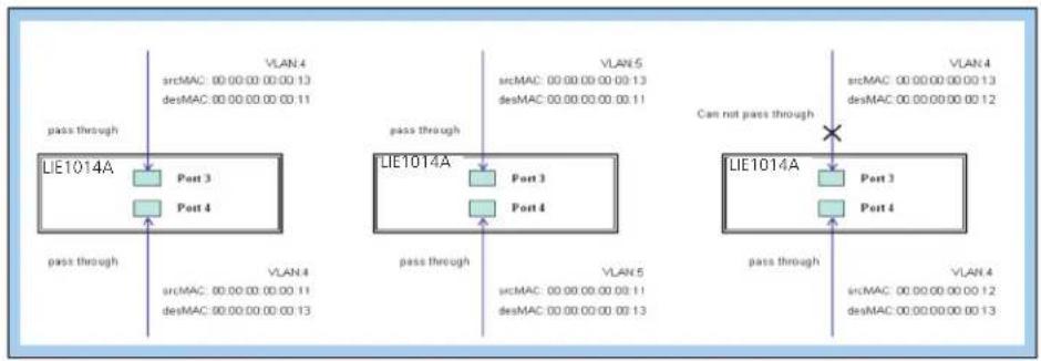
flowchart
graph TD
    subgraph Scenario 1
        A["pass through"] --> B["LIE1014A"]
        B --> C["Port 3"]
        B --> D["Port 4"]
        E["VLAN 4"] --> F["sicMAC: 00.00.00.00.00.13"]
        E --> G["desMAC: 00.00.00.00.00.11"]
    end
    subgraph Scenario 2
        H["pass through"] --> I["LIE1014A"]
        I --> J["Port 3"]
        I --> K["Port 4"]
        L["VLAN 5"] --> M["sicMAC: 00.00.00.00.00.13"]
        L --> N["desMAC: 00.00.00.00.00.11"]
    end
    subgraph Scenario 3
        O["Pass"] --> P["Can not pass through"]
        Q["VLAN 4"] --> R["sicMAC: 00.00.00.00.00.13"]
        Q --> S["desMAC: 00.00.00.00.00.12"]
    end
    B --> H
    I --> O
    I --> Q
    style A fill:#f9f,stroke:#333
    style H fill:#f9f,stroke:#333
    style O fill:#f9f,stroke:#333
Figure 4-18.
CLI Commands:
access-list ace 4 ingress interface GigabitEthernet 1/4 policy 3 tag tagged vid 4 frametype etype smac 00-00-00-00-00-11
exit
interface GigabitEthernet 1/3
switchport trunk allowed vlan 4,5
switchport trunk vlan tag native
!
interface GigabitEthernet 1/4
switchport trunk allowed vlan 4,5
switchport trunk vlan tag native
exit
To set two directional MAC addresses with all VLANs filtered:
STEP 1: Create a new ACL Profile. (Profile Name: AllowSomeMac)
STEP 2: Create a new ACL Entry rule under this ACL profile. (Allow SrcMAC: 13 and DesMAC: 11)
STEP 3: Bind this ACL profile to a GE port. (PORT-3)
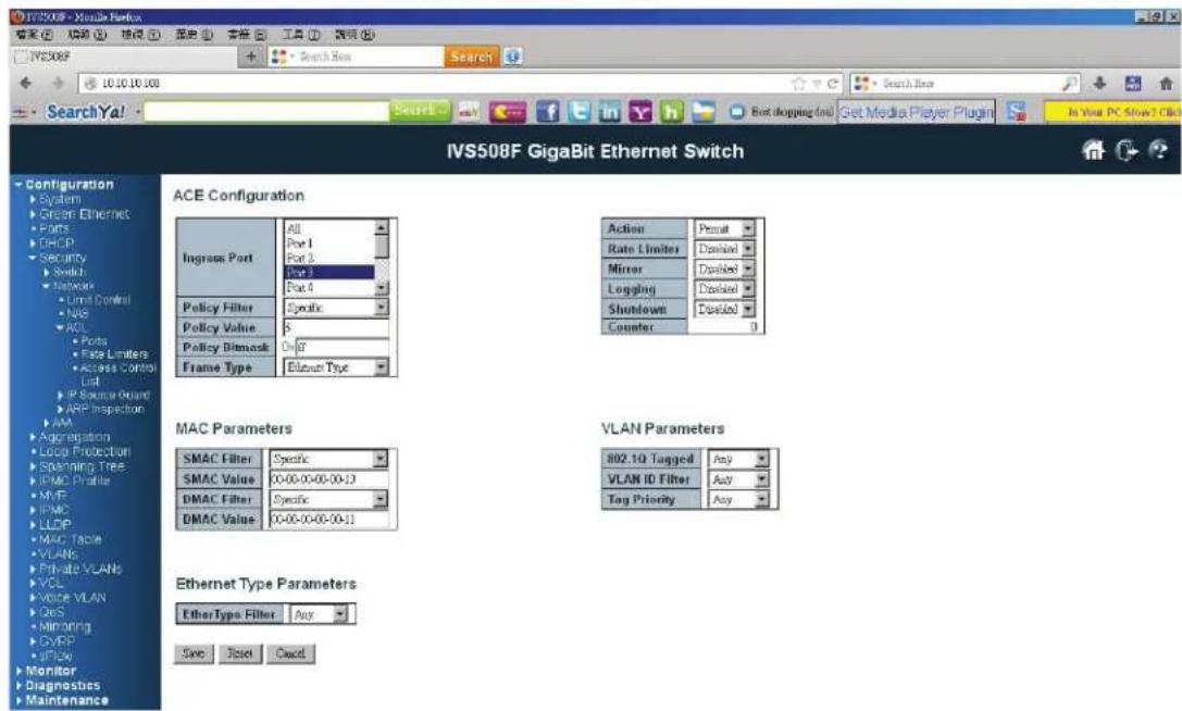
Figure 4-19.
STEP 4: Send frames between Port 3 and Port 4, and see the test result.
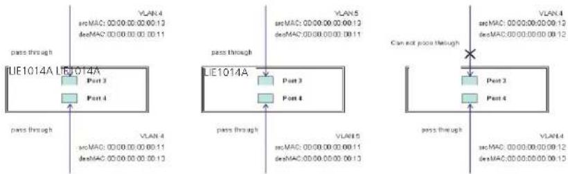
flowchart
graph TD
    subgraph VLAN_4
        A["srcMAC: 0000.00.00.00.12"]
        B["devMAC: 0000.00.00.00.11"]
    end
    subgraph VLAN_5
        C["srcMAC: 0000.00.00.00.12"]
        D["devMAC: 0000.00.00.00.11"]
    end
    subgraph IUE1014A
        E["Part 3"]
        F["Part 4"]
    end
    subgraph IUE1014A
        G["Part 3"]
        H["Part 4"]
    end
    IUE1014A -->|Pass through| IUE1014A
    IUE1014A -->|Pass through| IUE1014A
    IUE1014A -->|Pass through| IUE1014A
    IUE1014A -->|Can not poor through| IUE1014A
    IUE1014A -->|Pass through| IUE1014A
    IUE1014A -->|Pass through| IUE1014A
    IUE1014A -->|Pass through| IUE1014A
    IUE1014A -->|Pass through| IUE1014A
    IUE1014A -->|Pass through| IUE1014A
    IUE104A
    IUE104A -->|Pass through| IUE104A
    IUE104A -->|Pass through| IUE104A
    IUE104A -->|Pass through| IUE104A
Figure 4-20.
CLI Commands:
00-00-00-00-00-13 dmac 00-00-00-00-00-11
exit
interface GigabitEthernet 1/3
switchport trunk allowed vlan 4,5
switchport trunk vlan tag native
!
interface GigabitEthernet 1/4
switchport trunk allowed vlan 4,5
switchport trunk vlan tag native
exit
- Case 1: (h) Deny all frames.
The default ACL Rule of GE port is "Deny", so Queue Mapping is not needed in this case.
- Case 1: (i) Deny all frames.
Deny all frames.
The default ACL Rule of GE port is "Deny", so CoS Marking action is not needed in this case.
- Case 1: (j) Deny all frames.
Set the default ACL Rule of GE port as "Deny", then bind a suitable profile with "Copy Frame" action for the mirror analyzer used. The system will copy frames from the binding GE Port to analyzer port. No frames are received from the denied GE port but Only mirror analyzer port frames are received from the denied GE port.
To set one directional MAC address with Copy Frame:
STEP 1: Create a new ACL Profile. (Profile Name: CopyFrameTest)
STEP 2: Create a new ACL Entry rule under this ACL profile. (SrcMAC: 13 and DesMAC: 11)
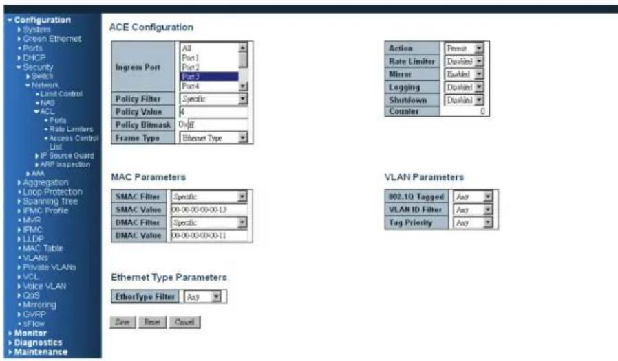
Figure 4-21.
STEP 3: Bind this ACL profile to a GE port. (Port 3)
STEP 4: Set the analyzer port to enable and mirror the analyzer port.
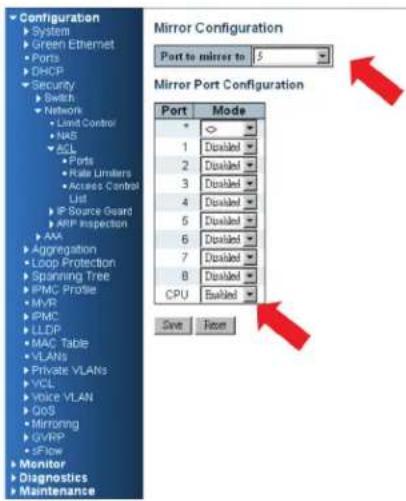
Figure 4-22.
STEP 5: Send frames between Port 3 and Port 4, and see the test result.
flowchart
graph TD
    subgraph VLAN_1
        A["srcMAC: 000000000013<br>devMAC: 00000000011"] --> B["Port 3"]
        C["Port 5"] --> D["Port 4"]
    end
    subgraph VLAN_2
        E["srcMAC: 000000000014<br>devMAC: 00000000011"] --> F["Port 3"]
        G["Port 5"] --> H["Port 4"]
    end
    subgraph VLAN_3
        I["srcMAC: 00000000011<br>devMAC: 000000UUU13"] --> J["Port 3"]
        K["Port 5"] --> L["Port 4"]
    end
    subgraph VLAN_4
        M["srcMAC: 00000000011<br>devMAC: 00000UUU13"] --> N["Port 3"]
        O["Port 5"] --> P["Port 4"]
    end
    subgraph VLAN_5
        Q["srcMAC: 0000000011<br>devMAC: 00UUUUU13"] --> R["Port 3"]
        S["Port 5"] --> T["Port 4"]
    end
    A -->|Pass through| B
    B -->|Pass through| C
    C -->|Pass through| D
    D -->|Pass through| E
    E -->|Pass through| F
    F -->|Pass through| G
    G -->|Pass through| H
    H -->|Pass through| I
    I -->|Pass through| J
    J -->|Pass through| K
    K -->|Pass through| L
    L -->|Pass through| M
    M -->|Pass through| N
    N -->|Pass through| O
    O -->|Pass through| P
    P -->|Pass through| Q
    Q -->|Pass through| R
    R -->|Pass through| S
    S -->|Pass through| T
    T -->|Pass through| U
    U -->|Pass through| V
    V -->|Pass through| W
    W -->|Pass through| X
    X -->|Pass through| Y
    Y -->|Pass through| Z
    Z -->|Pass through| AA
    AA -->|Pass through| AB
    AB -->|Pass through| AC
    AC -->|Pass through| AD
    AD -->|Pass through| AE
    AE -->|Pass through| AF
    AF -->|Pass through| AG
    AG -->|Pass through| AH
    AH -->|Pass through| AI
    AI -->|Pass through| AJ
    AJ -->|Pass through| AK
    AK -->|Pass through| AL
    AL -->|Pass through| AM
    AM -->|Pass through| AN
    AN -->|Pass through| AO
    AO -->|Pass through| AP
    AP -->|Pass through| AQ
    AQ -->|Pass through| AR
    AR -->|Pass through| AS
    AS -->|Pass through| AT
    AT -->|Pass through| AU
    AU -->|Pass through| AV
    AV -->|Pass through| AW
    AW -->|Pass through| AX
    AX -->|Pass through| AY
Figure 4-23.
CLI Commands:
access-list ace 5 next 6 ingress interface GigabitEthernet 1/3 policy 5 frametype etype smac
00-00-00-00-00-13 dmac 00-00-00-00-00-11
Exit
monitor destination interface GigabitEthernet 1/5
monitor source cpu both
exit
interface GigabitEthernet 1/3
switchport trunk allowed vlan 4,5
switchport trunk vlan tag native
!
interface GigabitEthernet 1/4
switchport trunk allowed vlan 4,5
switchport trunk vlan tag native
exit
4.2.3 Case 2: ACL for IP address
For IP address ACL, the switch can filter source IP address, destination IP address, or both. You can set an IP range ACL. When the switch filters both IP addresses, packets that coincide with both rules will take effect. In other words, the switch does filter ACL for IP address if it only coincides with one rule.
To filter only one directional IP address, set the other IP address to all zeros. The switch also filters Protocols (TCP=6, UDP=17, etc.) Certain Protocols under these IP addresses will take effect. If you don't want the switch to filter Protocol, set it to zero. For details about testing, refer to MAC ACL above.
4.2.4 Case 3: ACL for L4 Port
For Layer 4 port ACL, the switch can filter (1) source IP address, (2) source L4 port, (3) destination IP address, (4) destination L4 port, and (5) UDP or TCP Protocol. You can filter (1)-(4) for all or some specific values, but you should select exactly one Protocol from UDP or TCP.
When it filters both directional IP address and L4 port, packets that coincide with both rules will take effect. In other words, the switch does not filter if it only coincides with one rule.
To filter only one directional IP address or L4 port, set the other IP address and the L4 port to all zeros. For details about testing, refer to MAC ACL above.
4.2.5 Case 4: ACL for ToS
For Type of Service (ToS) ACL, the switch can filter (1) source IP address with ToS type, (2) destination IP address with ToS type, or (3) both, or (4) neither (if you select neither, the switch just filters ToS). When it filters both IP addresses, packets that coincide with both rules will take effect. In other words, the switch does not filter if it only coincides with one rule.
To filter only one directional IP address, set the other IP addresses to all zeros. For details about testing, refer to Case 1: MAC ACL above.
Valid Values: Precedence: 0–7, ToS: 0–15, DSCP: 0–63
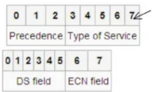
This value (7) is reserved and set to 0.
Ex: Pre (001) means 1
Pre (100) means 4
ToS (00010) means 1
ToS (10000) means 8
DSCP (000001) means 1
DSCP (100000) means 32
Figure 4-24.
4.3 Ring Protection Application Guide
4.3.1 Explanation of Ring Protection
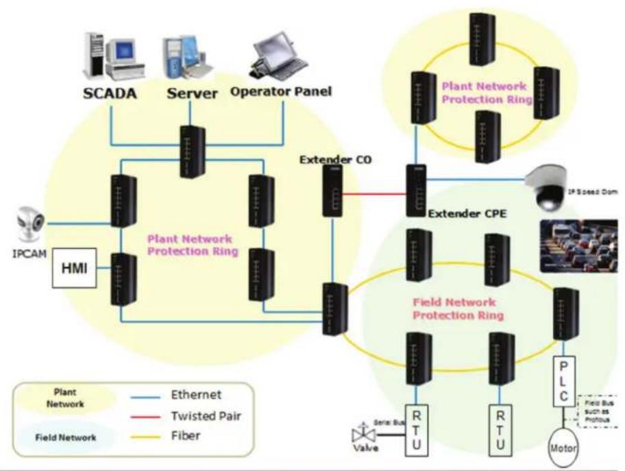
A reliable network is very important in industrial Ethernet applications.
The LIG1014A/LIE1014A switch provides millisecond-grade failover ring protection; this feature offers a seamless working network even if connections create issues. Ring Protection works with both Ethernet and fiber cable.
flowchart
graph TD
    A["SCADA"] --> B["Server"]
    B --> C["Operator Panel"]
    C --> D["Extender CO"]
    D --> E["Field Network Protection Ring"]
    E --> F["PLC"]
    F --> G["Motor"]
    H["IPCAM"] --> I["HMI"]
    I --> J["SCADA"]
    K["Plant Network Protection Ring"] --> L["Extender CO"]
    L --> M["Field Network Protection Ring"]
    M --> N["PLC"]
    O["IP Speed Dom"] --> P["Extender CPE"]
    P --> Q["Field Network Protection Ring"]
    Q --> R["PLC"]
    S["Tube"] --> T["Valve"]
    U["Tube"] --> V["Tube Bus"]
    W["Tube Bus"] --> X["Tube Bus such as Profusus"]
    Y["Tube Bus"] --> Z["Tube Bus such as Profusus"]
    style A fill:#f9f,stroke:#333
    style B fill:#f9f,stroke:#333
    style C fill:#f9f,stroke:#333
    style D fill:#f9f,stroke:#333
    style E fill:#f9f,stroke:#333
    style F fill:#f9f,stroke:#333
    style G fill:#f9f,stroke:#333
    style H fill:#f9f,stroke:#333
    style I fill:#f9f,stroke:#333
    style J fill:#f9f,stroke:#333
    style K fill:#f9f,stroke:#333
    style L fill:#f9f,stroke:#333
    style M fill:#f9f,stroke:#333
    style N fill:#f9f,stroke:#333
    style O fill:#f9f,stroke:#333
    style P fill:#f9f,stroke:#333
    style Q fill:#f9f,stroke:#333
    style R fill:#f9f,stroke:#333
    style S fill:#f9f,stroke:#333
    style T fill:#f9f,stroke:#333
    style U fill:#f9f,stroke:#333
    style V fill:#f9f,stroke:#333
    style W fill:#f9f,stroke:#333
Figure 4-25.
4.3.2 Configuration (Console)
To configure ring protection on the LIG1014A/LIE1014A switch:
- Login as "admin" in the console interface.
- Go to Configure mode via the "configure terminal" command.
- Go to Configure Ring Protection via the "ring protect" command.
- Go to configure ring protection group1 via the "group1" command.
-
Before configuring the console, you must disable ring protection status using the "mode disable" command.
-
To set all necessary parameters:
-
For Node 1 and Node 2, choose the ports that you want to connect to the other switch.
- For example, if you choose Port 1 and Port 2, then Port 1 and Port 2 are both connected to the other switch.
- Choose one of ring connection devices as "Master." The "Node 2 port" will be the blocking port for the master device.
id 1
node1 interface GigabitEthernet 1/1
node2 interface GigabitEthernet 1/2
Role Master node1 interface GigabitEthernet 1/1
node2 interface GigabitEthernet 1/2
- To finish this configuration, you must enable ring protection status by selecting the "mode enable" command.
NOTE: Pay attention to the of "Previous Command Result" status after every action.
configure terminal
ring protect
group1
mode disable
id 1
node1 interface GigabitEthernet 1/1
node2 interface GigabitEthernet 1/2
Role Master
mode enable
exit
4.3.3 Configuration (Web UI)
flowchart
graph TD
    A["Central Management Switch SWM"] --> B["SW11"]
    A --> C["SW12"]
    A --> D["SW13"]
    A --> E["SW14"]
    A --> F["SW21"]
    A --> G["SW22"]
    A --> H["SW24"]
    B --> I["Ring 1"]
    C --> J["Ring 1"]
    D --> K["Ring 1"]
    E --> L["Ring 1"]
    F --> M["Ring 1"]
    G --> N["Ring 2"]
    H --> O["Ring 2"]
Figure 4-26.
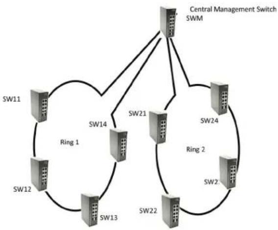
STEP 1: Set RSTP on the central switch.
NOTE: The administrator must configure STP mode on the central switch "SWM."
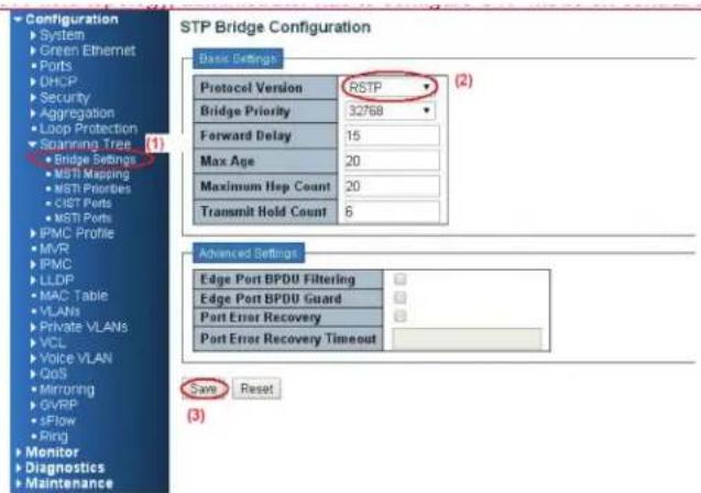
Figure 4-27.
- Go to the "Configuration—>Spanning Tree—>Bridge Setting" Web page.
- Select "Protocol Version" as "RSTP."
- Click the "Save" button.
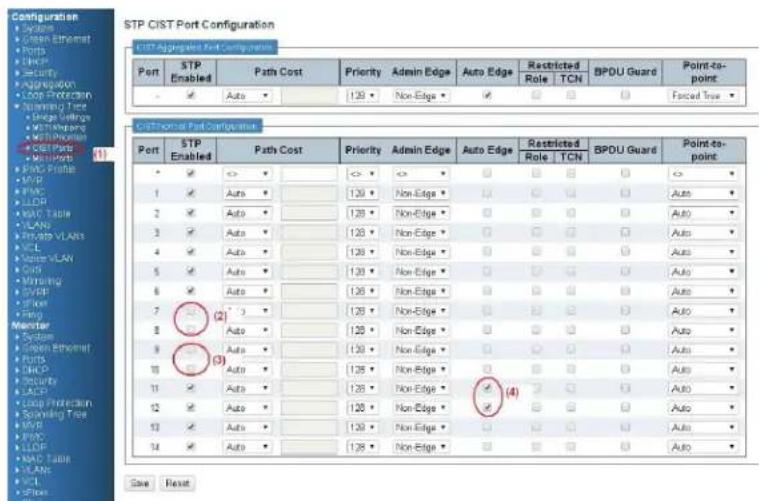
Figure 4-28.
- Go to the "Configuration—>Spanning Tree—>CIST ports" Web page.
- Do not enable Port 7 or 8, check box for ring 1.
- Do not enable Port 9 or 10, check box for ring 2.
- Check "Auto Edge" on Port 11 and 12.
- Click the "Save" button.
STEP 2: Set ring protection on the central switch.
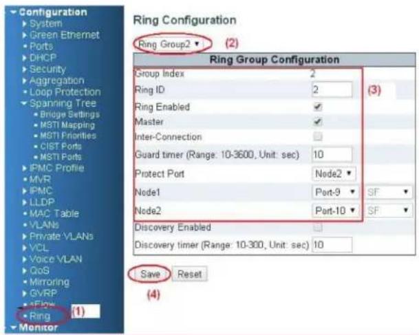
Figure 4-29.
- Go to the "Configuration—>Ring" Web page.
- Select "Ring Group 1"
-
Ring ID 1 Check "Ring Enable," and "Master." Set Port 7 as Node 1 and Port 8 as Node 2.
-
Click the "Save" button.
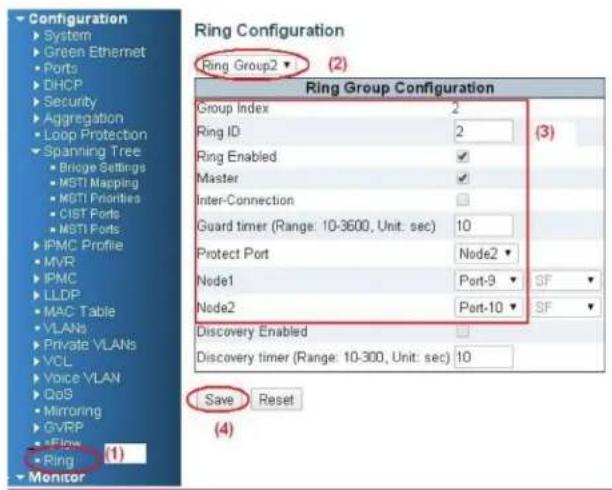
Figure 4-30.
- Go to the "Configuration—>Ring" Web page.
- Select "Ring Group 2."
- Ring ID 2
Check "Ring Enable," and "Master."
Set Port 9 as Node 1 and Port 10 as Node 2.
- Click the "Save" button.
Follow the instructions in the screen shown next to save running configuration.
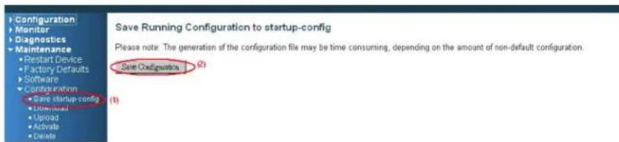
Figure 4-31.
STEP 3: Configure ring protection on switches SW11, SW12, SW13, and SW14.
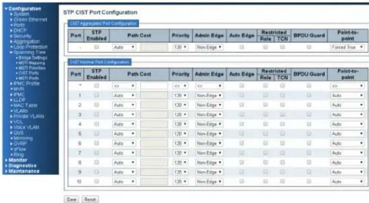
Figure 4-32.
- Go to the Configuration —>Spanning Tree—>CIST ports Web page.
- Do not enable the STP check box for ring configuration.
- Click the "Save" button.
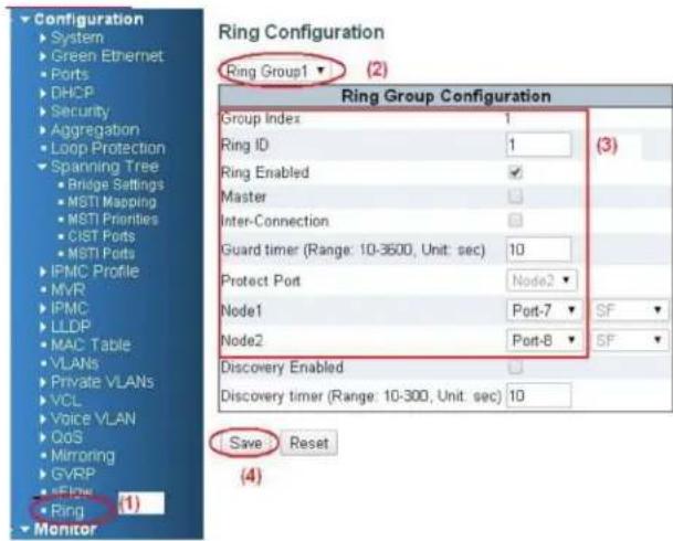
Figure 4-33.
- Go to the "Configuration—>Ring" Web page.
- Select "Ring Group 1."
- Ring ID 1
Check "Ring Enable."
Set Node 1 as Port 7, and node 2 as Port 8.
- Click the "Save" button.
Then save the running configuration.
STEP 4: Configure ring protection on switches SW21, SW22, SW23, and SW24.
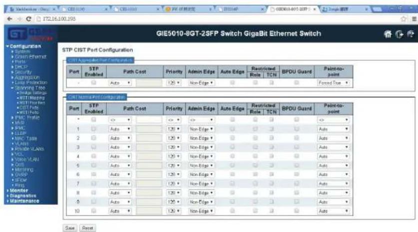
Figure 4-34.
- Go to the Configuration —>Spanning Tree—>CIST ports Web page.
- Do not enable the STP check box for ring configuration.
- Click the "Save" button.
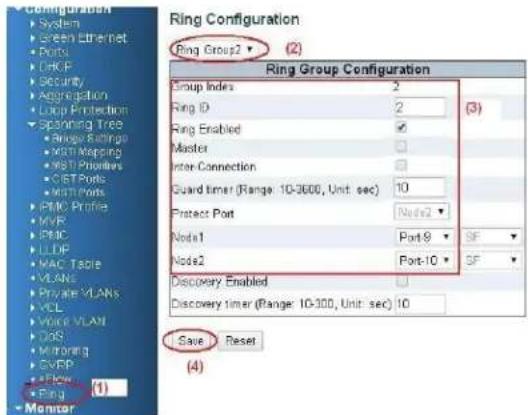
Figure 4-35.
- Go to the "Configuration—>Ring" Web page.
- Select "Ring Group 2."
- Ring ID 2
Check "Ring Enable."
Set Node 1 as Port 9, and node 2 as Port '0.
- Click the "Save" button.
Then save the running configuration.
4.3.4 Dual Ring
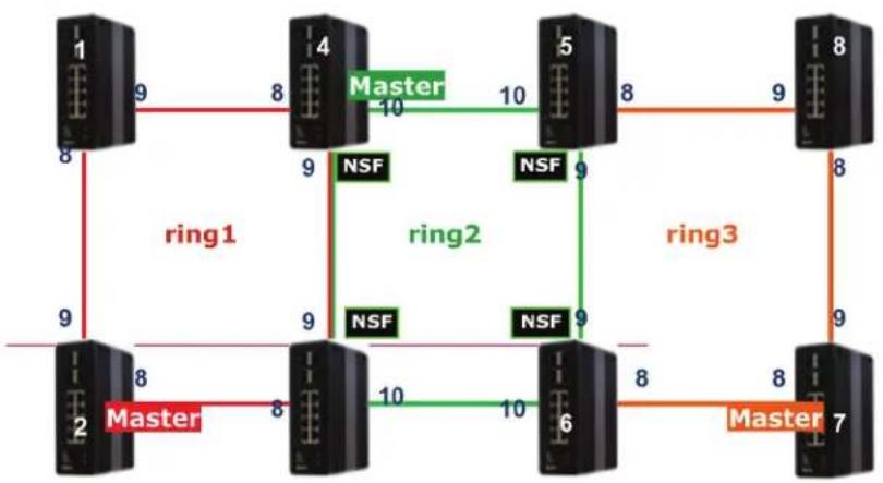
Feature: Interconnection ports can belong to two neighbor ring groups.
Advantage: You can run the ring function on just one port.
flowchart
graph TD
    subgraph Ring1
        1["1"] -->|8| 4["4"]
        4 -->|9| 2["2"]
        2 -->|8| 6["6"]
        6 -->|10| 5["5"]
        5 -->|10| 8["8"]
        8 -->|9| 7["7"]
    end
    subgraph Ring2
        4 -->|9| 5
        5 -->|9| 6
        6 -->|10| 7
        7 -->|9| 8
        8 -->|8| 7
    end
    subgraph Ring3
        5 -->|9| 6
        6 -->|10| 7
        7 -->|8| 8
        8 -->|9| 7
    end
    Ring1 -->|ring1| 4
    Ring2 -->|ring2| 5
    Ring3 -->|ring3| 7
Figure 4-36.
Configure Steps:
- Disable RSTP on all ring ports.
- Select a master port in every ring group.
- Configure ring protection on the ring 2 group.
- Configure ring protection on the other ring group device.
NOTE: Rules:
- Any device with a master port cannot connect with another device with a master port.
- The NSF ports are member ports of the middle ring group.
- The ring groups can up to three in a dual-ring scenario.
- Any device that belongs to two ring groups is an inter-connection device.
Configure ring protection on the middle ring group (ring2).
On device 4 (ring 2 master):
- Go to the "Configuration—>Ring" Web page.
- Select "Ring Group 2."
-
Ring ID 2
Check "Ring Enable," "Interconnection," and "Master."
Protect Port and NSF is on "Node 1 (port 9)."
Node 1 is "Port 9," and node 2 is "Port 10." -
Click the "Save" button.
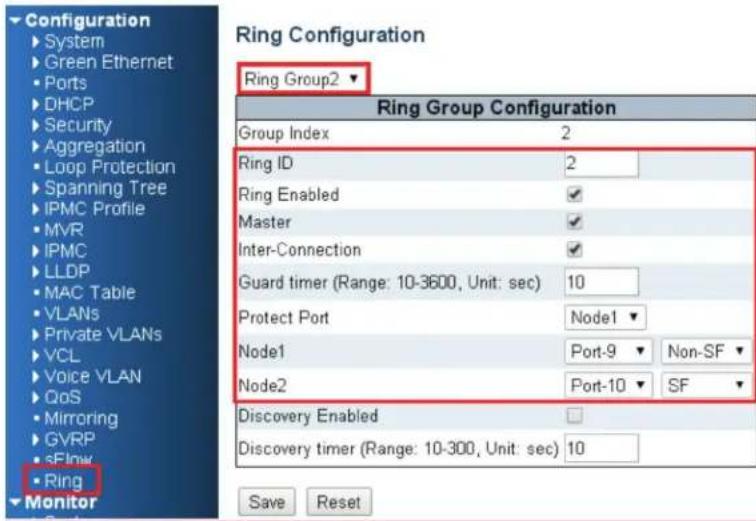
Figure 4-37.
On devices 3, 5, and 6 (ring 2 slave):
- Select "Ring Group 2."
- Ring ID 2
Check "Ring Enable" and "Interconnection,"
NSF is on "Node 1 (port 9)."
Node 1 is "Port 9," and node 2 is "Port 10." - Click the "Save" button.
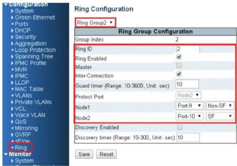
Figure 4-38.
Configure ring protection on the side ring group (ring 1 and 3).
On device 2 and 7 (master):
- Select "Ring Group 1 (or 3)"
- Ring ID 1 (or 3)
Check "Ring Enable", and "Master".
Protect Port is on "Node1 (port 9)"
Node 1 will be "Port 9", and node 2 will be "Port 10."
- Click the "Save" button.
On device 1 and 8 (slave):
- Select "Ring Group 1 (or 3)"
- Ring ID 1(or 3)
Check "Ring Enable"
Node 1 will be "Port 9", and node 2 will be "Port 8"
- Click the "Save" button.
On device 3–6 (slave) + Inter-connection:
- Select "Ring Group 1 (or 3)"
- Ring ID 1(or 3)
- Check "Ring Enable," and "Inter-connection"
Node 1 will be "Port 9", and node 2 will be "Port 8"
- Click the "Save" button.
4.3.5 Dual Homing
Feature: Dual homing devices (switch 6) enable two ring groups.
Advantage: Recovery time is less than "dual ring," and you can connect two dual ring systems.
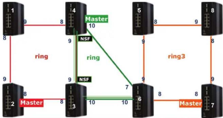
flowchart
graph TD
    A["1"] -->|8| B["2"]
    B -->|8| C["3"]
    C -->|9| D["4"]
    D -->|10| E["5"]
    E -->|8| F["6"]
    F -->|7| G["7"]
    G -->|8| H["8"]
    H -->|9| I["8"]
    I -->|8| J["7"]
    J -->|8| K["Master"]
    style A fill:#f9f,stroke:#333
    style B fill:#f9f,stroke:#333
    style C fill:#f9f,stroke:#333
    style D fill:#f9f,stroke:#333
    style E fill:#f9f,stroke:#333
    style F fill:#f9f,stroke:#333
    style G fill:#f9f,stroke:#333
    style H fill:#f9f,stroke:#333
    style I fill:#f9f,stroke:#333
    style J fill:#f9f,stroke:#333
    style K fill:#f9f,stroke:#333
Figure 4-39.
Configure Steps:
- Disable RSTP on all ring ports.
- Select a master port in every ring group.
- Configure ring protection on ring 2 group.
- Configure ring protection on other ring group devices.
Compare to Dual Ring, but only modify devices 5 and 6.
On device 5 (slave):
- Select "Ring Group 3."
-
Ring ID
Check "Ring Enable."
Node 1 will be "Port 9, and node 2 will be "Port 8." -
Click the "Save" button.
On device 6 (slave):
- Select "Ring Group 3."
- Ring ID 3
Check "Ring Enable." - Node 1 will be "Port 9", and node 2 will be "Port 8."
- Select "Ring Group 2."
-
Ring ID 2
Check "Ring Enable"
Node 1 will be "Port 7," and node 2 will be "Port 10." -
Click the "Save" button.
4.4 Ring Version 2 Feature
4.4.1 Explanation of Ring Version 2
Ring Version 2 provides advanced ring protection for network rings using LIG1014A/LIE1014A switches.
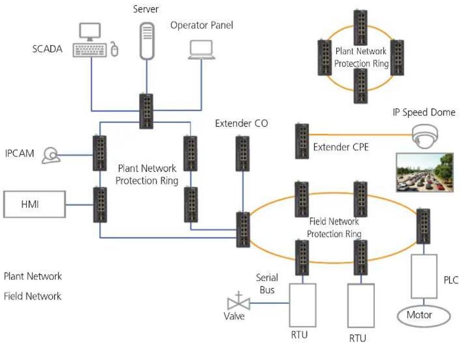
flowchart
graph TD
    A["SCADA"] --> B["Server"]
    B --> C["Operator Panel"]
    D["IPCAM"] --> E["Plant Network Protection Ring"]
    F["HMI"] --> E
    E --> G["Extender CO"]
    G --> H["Field Network Protection Ring"]
    I["Valve"] --> J["Serial Bus"]
    K["RTU"] --> L["PLC Motor"]
    M["RTU"] --> L
    N["PTL"] --> O["PTL"]
    P["PTL"] --> Q["PTL"]
    R["PTL"] --> S["PTL"]
    T["PTL"] --> U["PTL"]
    V["PTL"] --> W["PTL"]
    X["PTL"] --> Y["PTL"]
    Z["PTL"] --> AA["PTL"]
    AB["PTL"] --> AC["PTL"]
    AD["PTL"] --> AE["PTL"]
    AF["PTL"] --> AG["PTL"]
    AH["PTL"] --> AI["PTL"]
    AJ["PTL"] --> AK["PTL"]
    AL["PTL"] --> AM["PTL"]
    AN["PTL"] --> AO["PTL"]
    AP["PTL"] --> AQ["PTL"]
    AR["PTL"] --> AS["PTL"]
    AT["PTL"] --> AU["PTL"]
    AV["PTL"] --> AW["PTL"]
    AX["PTL"] --> AY["PTL"]
    AZ["PTL"] --> BA["PTL"]
    BB["PTL"] --> BC["PTL"]
    BD["PTL"] --> BE["PTL"]
    BF["PTL"] --> BG["PTL"]
    BH["PTL"] --> BI["PTL"]
    BJ["PTL"] --> BK["PTL"]
    BL["PTL"] --> BM["PTL"]
    BN["PTL"] --> BO["PTL"]
    BP["PTL"] --> BQ["PTL"]
    BR["PTL"] --> BS["PTL"]
    BT["PTL"] --> BU["PTL"]
    BV["PTL"] --> BW["PTL"]
    BX["PTL"] --> BY["PTL"]
    BZ["PTL"] --> CA["PTL"]
    CB["PTL"] --> CC["PTL"]
    DD["PTL"] --> EE["PTL"]
    FF["PTL"] --> DG["PTL"]
    DH["PTL"] --> DI["PTL"]
    DJ["PTL"] --> DK["PTL"]
    DL["PTL"] --> DM["PTL"]
    DB["PTL"] --> DE["PTL"]
    DF["PTL"] --> DG
    DG --> DG
    DG --> DK
    DG --> DE
    DG --> DE
    DG --> DE
    DG --> DE
    DG --> DE
    DG --> DE
    DG --> DE
    DG --> DE
    DG --> DE
    DG --> DE
    DG --> DE
    DG --> DE
    DG --> DE
    DG --> DE
    DG --> DE
    DG --> DE
    DG --> DE
    DG --> DE
    DG --> DE
    DG --> DE
    DG --> GE
    DG --> GE
    DG --> GE
    DG --> GE
    DG --> GE
    DG --> GE
    DG --> GE
    DG --> GE
    DG --> GE
    DG --> GE
    DG --> GE
    DG --> GE
    DG --> GE
    DG --> GE
    DG --> GE
    DG --> GE
    DG --> GE
    DG --> GE
    DG --> GE
    DG --> GE
    DG --> CE
    DG --> CE
    DG --> CE
    DG --> CE
    DG --> CE
    DG --> CE
    DG --> CE
    DG --> CE
    DG --> CE
    DG --> CE
    DG --> CE
    DG --> CE
    DG --> CE
    DG --> CE
    DG --> CE
    DG --> CE
    DG --> CE
    DG --> CE
    DG --> CE
    DG --> CE
    DG --> GE
    DG --> GE
    DG --> GE
    DG --> GE
    DG --> GE
    DG --> GE
    DG --> GE
    DG --> GE
    DG --> GE
    DG --> GE
    DG --> GE
    DG --> GE
    DG --> GE
    DG --> GE
    DG --> GE
    DG --> GE
    DG --> GE
    DG --> GE
    DG --> GE
    DG --> OE
Figure 4-40. Ring v2 configuration.
4.4.2 Group 1: Supports ring-master and ring-slave options
# Ring - This can be master or slave.
# When role is ring/master, one ring port is the forwarding port and another is the blocking port. The blocking port is a redundant port. It is blocked in the normal state.
# When role is ring/slave, both ring ports are forwarding ports.
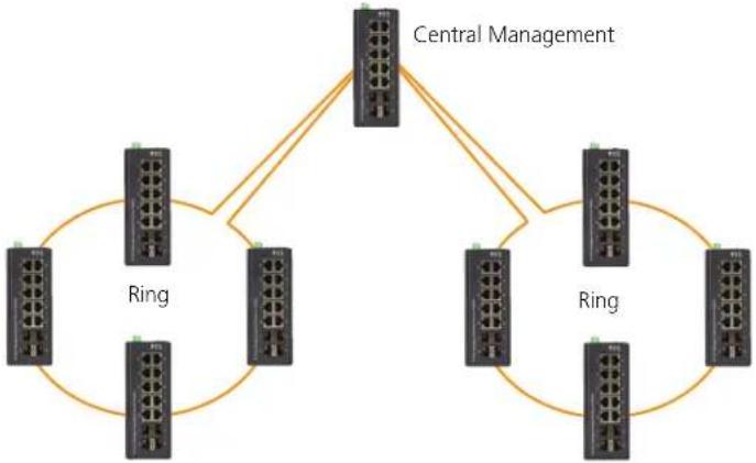
flowchart
graph TD
    A["Central Management"] --> B["Ring"]
    A --> C["Ring"]
    B --> D["Router 1"]
    B --> E["Router 2"]
    C --> F["Router 3"]
    C --> G["Router 4"]
    D --> H["Router 5"]
    E --> I["Router 6"]
    F --> J["Router 7"]
    G --> K["Router 8"]
    H --> L["Router 9"]
    I --> M["Router 10"]
    J --> N["Router 11"]
    K --> O["Router 12"]
Figure 4-41. Ring-master and ring-slave options.
4.4.3 Group 2: Supports ring, coupling, and dual-homing configurations
# Ring - This can be master or slave.
# Coupling - Can be primary and backup.
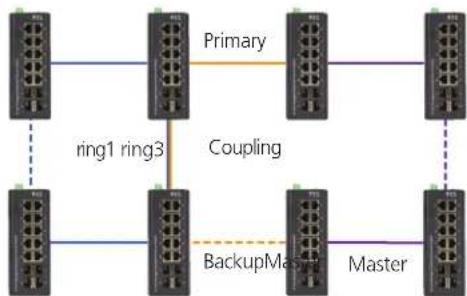
flowchart
graph TD
    A["Switch 1"] -->|ring1 ring3| B["Switch 2"]
    B -->|Coupling| C["Switch 3"]
    C -->|Primary| D["Switch 4"]
    D --> E["Switch 5"]
    E -->|BackupMaster| F["Switch 6"]
    F -->|Master| G["Switch 7"]
    G -->|Ring1 Ring3| B
Figure 4-42. Group 2: Ring configuration.
# When role is coupling/primary, you only need to configure one ring port named primary port.
When role is coupling/backup, you only need to configure one ring port named backup port. This backup port is a redundant port. In normal state, it is blocked.
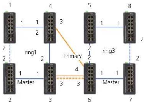
flowchart
graph TD
    1["Switch 1"] -->|1| 4["Switch 4"]
    1["Switch 2"] -->|2| 3["Switch 3"]
    2["Switch 2"] -->|ring1| 4["Switch 4"]
    3["Switch 3"] -->|1| 6["Switch 6"]
    4["Switch 4"] -->|3| 5["Switch 5"]
    5["Switch 5"] -->|1| 8["Switch 8"]
    6["Switch 6"] -->|1| 7["Switch 7"]
    7["Switch 7"] -->|2| 8["Switch 8"]
    4["Switch 3"] -->|2| 5["Switch 5"]
    5["Switch 5"] -->|1| 8["Switch 8"]
    style 4 fill:#f9f,stroke:#333
    style 5 fill:#f9f,stroke:#333
    style 6 fill:#f9f,stroke:#333
    style 7 fill:#f9f,stroke:#333
    style 8 fill:#f9f,stroke:#333
    linkStyle 0 stroke:#ff0000,stroke-width:2px
    linkStyle 1 stroke:#ff0000,stroke-width:2px
    linkStyle 2 stroke:#ff0000,stroke-width:2px
    linkStyle 3 stroke:#ff0000,stroke-width:2px
    linkStyle 4 stroke:#ff0000,stroke-width:2px
    linkStyle 5 stroke:#ff0000,stroke-width:2px
    linkStyle 6 stroke:#ff0000,stroke-width:2px
    linkStyle 7 stroke:#ff0000,stroke-width:2px
    linkStyle 8 stroke:#ff0000,stroke-width:2px
Figure 4-43. Group 2: Coupling/primary and backup.
# When role is dual-homing, one ring port is primary port and another is backup port. This backup port is a redundant port. In normal state, it is blocked.
4.4.4 Group 3: This supports chain and balancing-chain configurations
# Chain - Can be head, tail, or member.
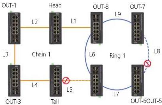
flowchart
graph TD
    OUT1["OUT-1"] -->|L2| Head["Head"]
    Head -->|L1| OUT8["OUT-8"]
    OUT8 -->|L9| OUT7["OUT-7"]
    OUT7 -->|L8| OUT6["OUT-6OUT-5"]
    OUT6 -->|L7| OUT5["OUT-5"]
    OUT5 -->|L4| Tail["Tail"]
    Tail -->|L3| OUT3["OUT-3"]
    Tail -->|L5| OUT5
    L3 -.-> Tail
    L4 -.-> Tail
    L6 -.-> Ring1["Ring 1"]
Figure 4-44. Group 3 configuration.
# When role is chain/head, one ring port is the head port and another is a member port. Both ring ports are forwarded in normal state.
# When role is chain/tail, one ring port is a tail port and another is a member port. The tail port is a redundant port. It is blocked in normal state.
# When role is chain/member, both ring ports are member ports. Both ring ports are forwarded in normal state.
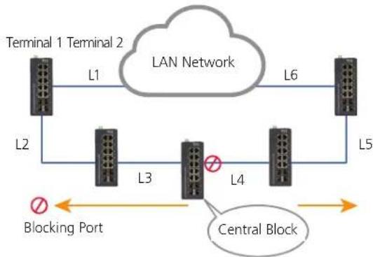
# Balancing Chain - This can be central-block, terminal-1/2, or member.
flowchart
graph TD
    A["Terminal 1 Terminal 2"] -->|L1| B["LAN Network"]
    B -->|L6| C["Terminal 1"]
    A -->|L2| D["L3"]
    D -->|L4| E["L4"]
    E --> F["Central Block"]
    F --> G["Blocking Port"]
    style A fill:#f9f,stroke:#333
    style B fill:#ccf,stroke:#333
    style C fill:#ccf,stroke:#333
    style D fill:#cfc,stroke:#333
    style E fill:#cfc,stroke:#333
    style F fill:#fcc,stroke:#333
    style G fill:#ffc,stroke:#333
Figure 4-45. Balancing chain.
# When role is balancing-chain/central-block, one ring port is a member port and another is a block port. The block port is a redundant port. It is blocked in normal state.
# When role is balancing-chain/terminal-1/2, one ring port is a terminal port and another is a member port. Both ring ports are forwarded in normal state.
# When role is balancing-chain/member, both ring ports are member ports. Both ring ports are forwarded in normal state.
NOTES:
- You must enable group1 before configuring group2 as coupling.
- When group1 or group2 is enabled, the group3 configuration is invisible.
- When group3 is enabled, group1 and group3 configurations are invisible.
4.5 Configuring Ringv2
4.5.1 Configuration (Console)
To configure the ring protection in the LIG1014A/LIE1014A switch:
- Log in as "admin" in the console.
- Go to Configure mode by selecting "configure terminal."
- Go to configure ring protection group by command "ringv2 protect group1."
-
Before configuring, disable ring protection status via the "mode disable" command.
-
Set all parameters:
For Node 1 and Node 2, choose the ports to connect another switch.
For example, if you choose PORT-1 and PORT-2, PORT-1 is one of the ports connected to another switch, so is PORT-2.
Choose one of ring connection devices to be "Master" with the "Node 2 port" as the blocking port.
id 1
node1 interface GigabitEthernet 1/1
node2 interface GigabitEthernet 1/2
role ring-master
To finish the configuration, enable ring protection status via the "mode enable" command.
NOTE: Check the status of the "Previous Command Result" after every action.
configure terminal
ring protect group1
mode disable
node1 interface GigabitEthernet 1/1
node2 interface GigabitEthernet 1/2
role ring-master
mode enable
exit
4.5.2 Configuration (Web UI)
This section introduces the Industrial Ethernet Switch Software Spec for Ringv2.
In our current design, one device supports 3 ring index, including ring, coupling, dual-homing, chain, and balancing-chain.
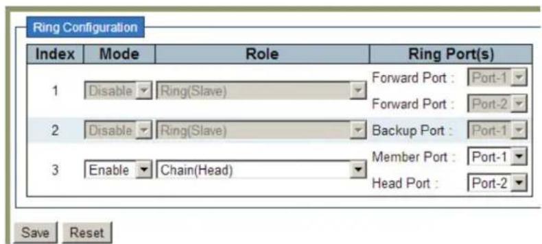
Figure 4-46. Ring configuration screen.
NOTES:
- You must enable group1 before configuring group2 as coupling.
- When group1 or group2 is enabled, the group3 configuration is invisible.
- When group3 is enabled, group1 and group2 configurations are invisible.
4.5.3 Disable RSTP on All Ring Ports
- Go to "Configuration—>Spanning Tree—>CIST ports" Web page.
- Do not enable STP global.
- Click the "Save" button.
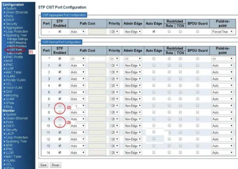
Figure 4-47. STP CIST Port Configuration screen.
4.5.4 Configuration (Ring Master)
- Go to "Configuration—>Ringv2" Web page.
- Enable Group1, and Select Role as "Ring(Master)."
- Select one port link to neighbor devices as "Forward Port," another as "Block Port."
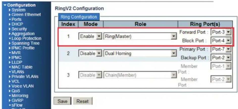
Figure 4-48. Ring v2 Configuration screen.
4.5.5 Ring Slave
- Go to the "Configuration—>Ringv2" Web page.
- Enable Group1, and Select the Role as "Ring(Slave)."
- Select two port links to neighbor devices as "Forward Port."
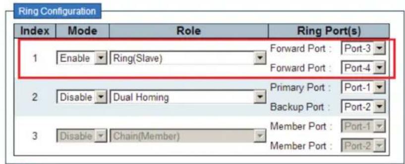
Figure 4-49.
4.5.6 Coupling Primary
- Go to "Configuration—>Ringv2" Web page.
- Enable Group1, and Select Role as "Ring(Slave)."
- Select two port links to neighbor devices as "Forward Port."
- Enable Group2, and Select Role be "Coupling(Primary)."
- Select one port link to above ring be "Primary Port."
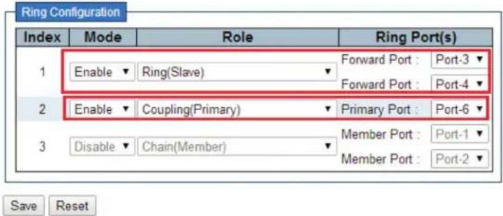
Figure 4-50.
4.5.7 Coupling Backup
- Go to "ConfigurationàRingv2" Web page.
- Enable Group1, and Select Role as "Ring(Slave)."
- Select two port links to neighbor devices as "Forward Port."
- Enable Group2, and Select Role as "Coupling(Backup)."
- Select one port link to above ring as "Backup Port."
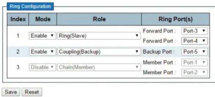
Figure 4-51.
4.5.8 Dual-Homing
- Go to "Configuration—>Ringv2" Web page.
- Enable Group2, and Select Role as "Dual Homing."
- Select one port link to ring to be "Primary Port."
- Select one port link to other ring to be "Backup Port."
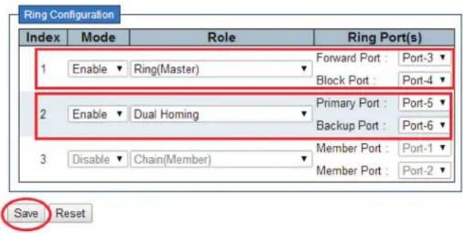
Figure 4-52.
4.5.9 Chain(Member)
- Go to "Configuration—>Ringv2" Web page.
- Enable Group3 amd select role as "Chain (Member)."
- Select two port links as member ports.
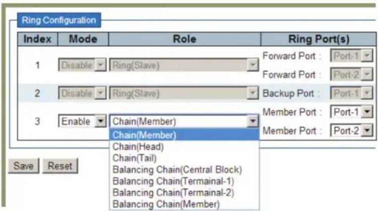
Figure 4-53.
4.5.10 Chain(Head)
- Go to "Configuration—>Ringv2" Web page.
- Enable Group3, and Select Role as "Chain(Head)."
- Select one port link to other ring or networks as "Head Port."
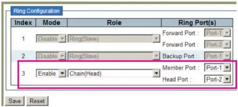
Figure 4-54.
4.5.11 Chain(Tail)
- Go to "Configuration—>Ringv2" Web page.
- Enable Group3, and Select Role as "Chain(Tail)."
- Select one port link to other ring or networks as "Tail Port."
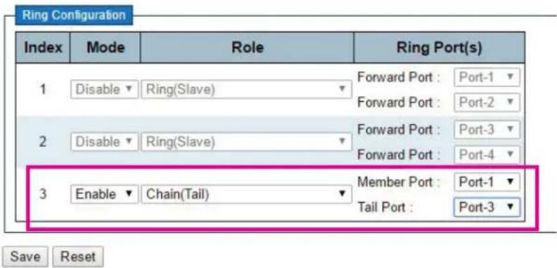
Figure 4-55.
4.5.12 Balance Chain(Central Block)
- Go to "Configuration—>Ringv2" Web page.
- Enable Group3, and Select Role as "Balance Chain(Central Block)."
- Select one port as "Block Port" that can distribute traffic loading.
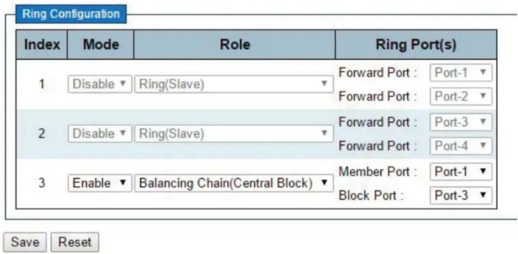
Figure 4-56.
4.5.13 Balance Chain(Terminal)
- Go to "Configuration—>Ringv2" Web page.
- Enable Group3, and Select Role as "Balance Chain(Terminal-1(or2)."
- Select one port as "Terminal Port" that connects to the other ring group.
RingV2 Configuration
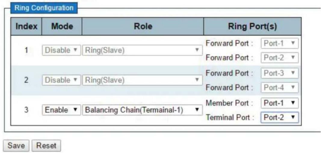
Figure 4-57.
4.6 QoS Application Guide
4.6.1 Explanation of QoS
Quality of Service (QoS) features allow you to allocate network resources to mission-critical applications at the expense of applications that are less sensitive to factors such as time delays or network congestion. You can configure your network to prioritize specific types of traffic, ensuring that each type receives the appropriate Quality of Service (QoS) level.
4.6.2 SP/SPWRR/WRR
The LIG1014A/LIE1014A can be configured to have 8 output Class of Service (CoS) queues (Q0–Q7) per port, into which each packet is placed. Q0 is the highest priority Queue. Each packet's 802.1p priority determines its CoS queue. You need to bind VLAN priority/queue mapping profile to each port, and, for every VLAN priority, assign a traffic descriptor. The traffic descriptor defines the shapping parameter on every VLAN priority for Ethernet interface. Currently LIG1014A/LIE1014A supports Strict Priority (SP)/SPWRR (SP+WRR)/WRR (Weighted Round Robin) scheduling methods on each port.
Table 4-2. Default Priority and Queue mapping.
| Priority0 | Priority1 | Priority2 | Priority3 | Priority4 | Priority5 |
| Queue0 | Queue1 | Queue2 | Queue3 | Queue4 | Queue5 |
| WRR | WRR | WRR | WRR | SPQ | SPQ |
Application Examples
Several examples for various QoS combinations are listed next. You can configure QoS using the Web-based management system, CLI (Command Line Interface), or SNMP.
4.6.3 Example 1: SPQ without Shaping (Default profile)
Send 2 Streams (Stream 0, Stream 1) from Port 1 to Port 2. Both streams are running at 100 Mbps. Stream 0 includes VLAN Priority 0, Stream 1 includes VLAN Priority 7. Set Port 2 link speed to 100 Mbps.
Expected Result:
Port 2 only can receive 100 Mbps of Stream 1, and Stream 0 will be discarded.
Gigabit port VLAN Priority & Queue mapping:
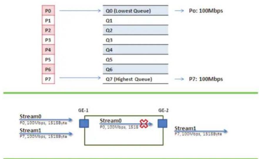
flowchart
graph LR
    subgraph Stream0
        P0["P0"] --> Q0["Q0 (Lowest Queue)"]
        P1["P1"] --> Q0
        P2["P2"] --> Q1
        P3["P3"] --> Q2
        P4["P4"] --> Q3
        P5["P5"] --> Q4
        P6["P6"] --> Q5
        P7["P7"] --> Q6
        Q0 --> Po["Po: 100Mbps"]
        Q1 --> Po
        Q2 --> Po
        Q3 --> Po
        Q4 --> Po
        Q5 --> Po
        Q6 --> Po
        Q7 --> Po
    end

    subgraph Stream1
        GE1["GE-1"] -->|P0, 100Mbps, 1518Byte| Stream0["Stream0"]
        GE2["GE-2"] -->|P0, 100Mbps, 1518Byte| Stream0
        Stream0 -->|P7, 100Mbps, 1518Byte| Stream1["Stream1"]
    end
Figure 4-55.
- Stream 0:
Dst Mac: 00:00:00:00:20:01
Src Mac: 00:00:00:00:10:01
Vlan:100
Vlan prio: 0
Send rate: 100 Mbps
Packet length: 1518 bytes
- Stream 1: Dst Mac: 00:00:00:00:20:02 Src Mac: 00:00:00:00:10:02
Vlan: 100
Vlan prio: 7
Send rate: 100 Mbps
Packet length: 1518 bytes
Web management:
Step 1. Go to Configuration —> Ports —> set port 2 link speed to 100 Mbps full duplex.
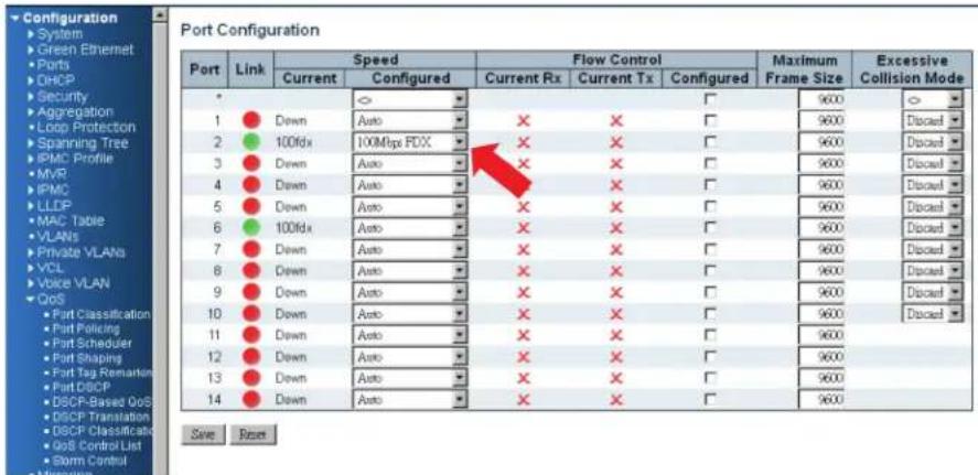
Figure 4-56.
Step 2. Select Configuration—> VLANs —>Create a VLAN with VLAN ID 100. Enter a VLAN name in the Name field. Here we set tagged VLAN 100 on Port 1 and Port 2.
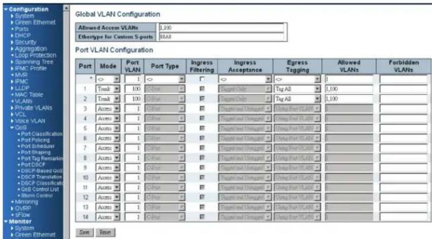
Figure 4-57.
CLI configuration commands:
interface GigabitEthernet 1/2
speed 100
duplex full
exit
vlan 100
4.6.4 Example 2: SPQ with Shaping
Send two Streams (Stream 0, Stream 1) from port 1 to port 2. Both streams are running at 100 Mbps. Stream 0 includes VLAN Priority 0, Stream 1 includes VLAN Priority 7. Stream 3 and Stream 4 are used only for learning which to make sure the traffic does not flood.
Expected Result:
Port 2 only can receive 20 Mbps of Stream 1, and 80 Mbps of Stream 0.
VDSL port VLAN Priority & Queue mapping:
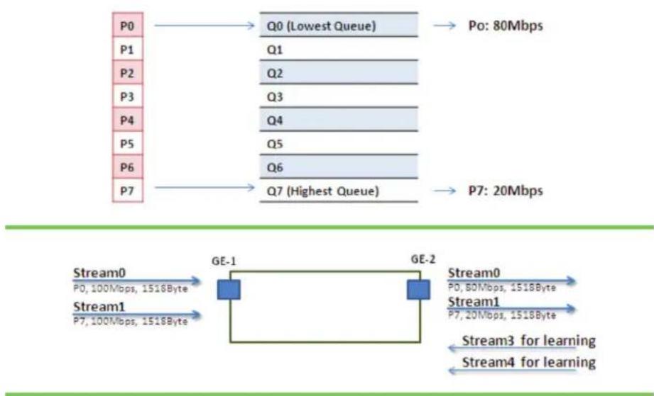
flowchart
graph LR
    P0[" P0 "] --> Q0[" Q0 (Lowest Queue) "]
    P1[" P1 "] --> Q1[" Q1 "]
    P2[" P2 "] --> Q2[" Q2 "]
    P3[" P3 "] --> Q3[" Q3 "]
    P4[" P4 "] --> Q4[" Q4 "]
    P5[" P5 "] --> Q5[" Q5 "]
    P6[" P6 "] --> Q6[" Q6 "]
    P7[" P7 "] --> Q7[" Q7 (Highest Queue) "]

    Q0 --> Po[" Po: 80Mbps "]
    Q1 --> Po
    Q2 --> Po
    Q3 --> Po
    Q4 --> Po
    Q5 --> Po
    Q6 --> Po
    Q7 --> Po

    P7 --> P7a[" P7: 20Mbps "]

    Stream0[" Stream0 "]
    Stream1[" Stream1 "]
    Stream2[" Stream2 "]
    Stream3[" Stream3 for learning "]
    Stream4[" Stream4 for learning "]

    GE-1[" GE-1 "]
    GE-2[" GE-2 "]

    style P0 fill:#f9f,stroke:#333
    style P1 fill:#f9f,stroke:#333
    style P2 fill:#f9f,stroke:#333
    style P3 fill:#f9f,stroke:#333
    style P4 fill:#f9f,stroke:#333
    style P5 fill:#f9f,stroke:#333
    style P6 fill:#f9f,stroke:#333
    style P7 fill:#f9f,stroke:#333

    %% Note: The diagram shows a network packet structure with multiple streams and their respective data packets. The labels 'Q0' and 'Q1' appear to be extracted from the image, not part of the chart type. The arrows indicate the direction of the flow from left to right. The text 'Stream0' and 'Stream1' are in the bottom row. The arrows are labeled 'Stream0', 'Stream1', 'Stream3' and 'Stream4' respectively. The arrows are also labeled 'Stream3 for learning'.]
Figure 4-58.
- Stream 0:
Dst Mac: 00:00:00:00:20:01
Src Mac: 00:00:00:00:10:01
Vlan: 100
Vlan prio: 0
Send rate: 100Mbps
Packet length: 1518 bytes
- Stream 1:
Dst Mac: 00:00:00:00:20:02
Src Mac: 00:00:00:00:10:02
Vlan: 100
Vlan prio: 7
Send rate: 100 Mbps
Packet length: 1518 bytes
- Stream 3: (for Learning)
Dst Mac: 00:00:00:00:10:01
Src Mac: 00:00:00:00:20:01
Vlan: 100
Vlan prio: 0
Send rate: 10 Mbps
Packet length: 1518 bytes
- Stream 4: (for Learning)
Dst Mac: 00:00:00:00:10:02
Src Mac: 00:00:00:00:20:02
Vlan: 100
Vlan prio: 0
Send rate: 10Mbps
Packet length: 1518 bytes
Web management:
STEP 1: Go to Configuration —> Qos—>Port Shaping, to create a Qos profile on Port 2.
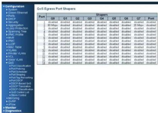
Figure 4-59.
STEP 2: Select schedule mode as ““Strict Priority” and set shaping rate for queue 0 and queue 7 as described next.
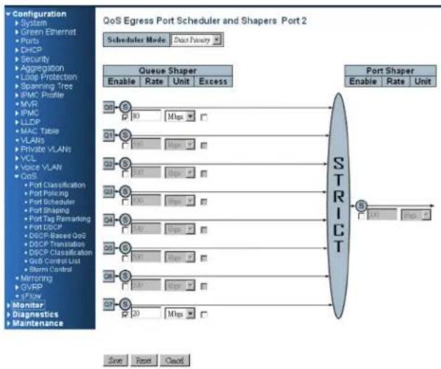
flowchart
graph TD
    A["Queue Shaper"] --> B["Enable Rate Unit Excess"]
    C["Port Shaper"] --> D["Enable Rate Unit"]
    B --> E["80 Mbps"]
    D --> F["4.5 Mbps"]
    E --> G["7.5 Mbps"]
    F --> H["3.5 Mbps"]
    G --> I["1.5 Mbps"]
    H --> J["1.5 Mbps"]
    I --> K["1.5 Mbps"]
    J --> L["1.5 Mbps"]
    K --> M["1.5 Mbps"]
    L --> N["1.5 Mbps"]
    M --> O["1.5 Mbps"]
    N --> P["1.5 Mbps"]
    O --> Q["1.5 Mbps"]
    P --> R["1.5 Mbps"]
    Q --> S["1.5 Mbps"]
    R --> T["1.5 Mbps"]
    S --> U["1.5 Mbps"]
    T --> V["1.5 Mbps"]
    U --> W["1.5 Mbps"]
    V --> X["1.5 Mbps"]
    W --> Y["1.5 Mbps"]
    X --> Z["1.5 Mbps"]
    Y --> AA["1.5 Mbps"]
    Z --> AB["1.5 Mbps"]
Figure 4-60.
CLI configuration commands:
vlan 100 v100
interface gigabit 1
vlan 100 tag
exit
interface gigabit 2
qos shaper 100000
qos queue-shaper queue 0 80000
qos queue-shaper queue 7 20000
exit
4.6.5 Example 3: WRR
Send three Streams (Stream 0, Stream 1, and Stream 2) from Port 1 to Port 2. These Streams each have 100 Mbps. Stream 0 includes VLAN Priority 0, Stream1 includes VLAN Priority 3, Stream2 includes VLAN Priority 7. Stream 3, Stream 4, and Stream 5 are used only for learning to make sure the traffic is not flooding. WRR supports weight assignment; the range of weight value is from 1 to 255. LIG1014A/LIE1014A applies WRR scheduling and weight 1 for all the Gigabit Ethernet ports. In the following case, assign Weight 2 for Priority 0, Weight 3 for Priority 3, and Weight 5 for Priority 7.
Expected Result:
Port 2 can receive about 20 Mbps of Stream 30 Mbps of Stream 1 and 50 Mbps of Stream 2.
Gigabit port VLAN Priority & Queue mapping:
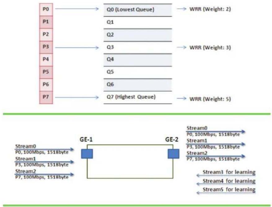
flowchart
graph TD
    P0[" P0 "] --> Q0[" Q0 (Lowest Queue) "]
    P1[" P1 "] --> Q1[" Q1 "]
    P2[" P2 "] --> Q2[" Q2 "]
    P3[" P3 "] --> Q3[" Q3 "]
    P4[" P4 "] --> Q4[" Q4 "]
    P5[" P5 "] --> Q5[" Q5 "]
    P6[" P6 "] --> Q6[" Q6 "]
    P7[" P7 "] --> Q7[" Q7 (Highest Queue) "]

    subgraph GE-1
        Stream0["Stream0<br>P0, 100Mbps, 1518byte"]
        Stream1["Stream1<br>P3, 100Mbps, 1518byte"]
        Stream2["Stream2<br>P7, 100Mbps, 1518byte"]
    end

    subgraph GE-2
        Stream0 --> Stream1 --> Stream2 --> Stream3 --> Stream4 --> Stream5 --> ... --> ... --> ... --> ... --> ... --> ... --> ... --> ... --> ... --> ... --> ... --> ... --> ... --> ... --> ... --> ... --> ... --> ... --> ... --> ... --> ... --> ... --> ... --> ... --> ... --> ... --> ... --> ... --> ... --> ... --> ... --> ... --> ... --> ... --> ... --> ... --> ... --> ... --> ... --> ... --> ... --> ... --> ... --> ... --> ... --> ... --> ... --> ... --> ... --> ... --> ...
    end
Figure 4-61.
- Stream 0:
Dst Mac: 00:00:00:00:20:01
Src Mac: 00:00:00:00:10:01
Vlan: 100
Vlan prio: 0
Send rate: 100 Mbps
Packet length: 1518 bytes
- Stream 1:
Dst Mac: 00:00:00:00:20:04
Src Mac: 00:00:00:00:10:04
Vlan: 100
Vlan prio: 3
Send rate: 100 Mbps
Packet length: 1518 bytes
- Stream 2:
Dst Mac : 00:00:00:00:20:08
Src Mac : 00:00:00:00:10:08
Vlan: 100
Vlan prio: 7
Send rate: 100 Mbps
Packet length: 1518 bytes
- Stream 3: (for Learning)
Dst Mac: 00:00:00:00:10:01
Src Mac: 00:00:00:00:20:01
Vlan: 100
Vlan prio: 0
Send rate: 10 Mbps
Packet length: 1518 bytes
-
Stream4: (for Learning)
Dst Mac: 00:00:00:00:10:04
Src Mac: 00:00:00:00:20:04
Vlan: 100
Vlan prio: 0
Send rate: 10 Mbps
Packet length: 1518 bytes -
Stream 5: (for Learning)
Dst Mac: 00:00:00:00:10:08
Src Mac: 00:00:00:00:20:08
Vlan: 100
Vlan prio: 0
Send rate: 10 Mbps
Packet length: 1518 bytes
Web management:
STEP 1: Go to Configuration—> Qos—> Port shaping, and click on Port 2 to create a Qos profile.
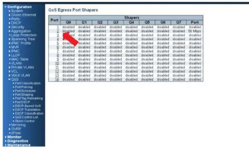
Figure 4-62.
STEP 2: Select schedule mode to “”Weighted” and set weight value for queue 0, queue 3, and queue 7 as described next.
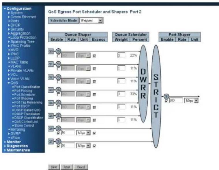
flowchart
graph TD
    A["Queue Shaper"] --> B["Enable Rate Unit Excess"]
    C["Queue Scheduler"] --> D["Weight Percent"]
    E["Port Shaper"] --> F["Enable Rate Unit"]
    G["QoS Egress Port Scheduler and Shapers Port 2"] --> H["DWRR"]
    I["QoS"] --> J["100 Mbps"]
    K["QoS"] --> L["50 Mbps"]
    M["QoS"] --> N["50 Mbps"]
    O["QoS"] --> P["50 Mbps"]
    Q["QoS"] --> R["50 Mbps"]
    S["QoS"] --> T["50 Mbps"]
    U["QoS"] --> V["50 Mbps"]
    W["QoS"] --> X["50 Mbps"]
    Y["QoS"] --> Z["50 Mbps"]
    AA["QoS"] --> AB["50 Mbps"]
    AC["QoS"] --> AD["50 Mbps"]
    AE["QoS"] --> AF["50 Mbps"]
    AG["QoS"] --> AH["50 Mbps"]
    AI["QoS"] --> AJ["50 Mbps"]
    AK["QoS"] --> AL["50 Mbps"]
    AM["QoS"] --> AN["50 Mbps"]
    AO["QoS"] --> AP["50 Mbps"]
    AQ["QoS"] --> AR["50 Mbps"]
    AS["QoS"] --> AT["50 Mbps"]
    AU["QoS"] --> AV["50 Mbps"]
    AW["STRICT"] --> AX["100 Mbps"]
Figure 4-63.
CLI configuration command:
interface GigabitEthernet 1/1
switchport trunk allowed vlan 1,100
switchport hybrid allowed vlan 1,100
switchport trunk vlan tag native
switchport mode trunk exit
interface GigabitEthernet 1/2
switchport trunk allowed vlan 1,100
switchport trunk vlan tag native
switchport mode trunk
qos shaper 100000
qos queue-shaper queue 6 50000 excess
qos queue-shaper queue 7 50000 excess
qos wrr 2 1 1 3 1 1
exit
4.6.6 Example 4 SP-WRR
Send 4 Streams (Stream 0, Stream 1, Stream 2, and Stream 3) from Port 1 to Port 2. These Streams each have 100 Mbps. Stream 0 includes VLAN Priority 0, Stream 1 includes VLAN Priority 1, Stream 2 includes VLAN Priority 2, Stream 3 includes VLAN Priority 3, and Stream 4 includes VLAN Priority 6. Stream 5, Stream 6, Stream 7, Stream 8, and Stream 9 are used only for learning to make sure traffic is not flooding. WRR supports a range of weight values from 1 to 255. LIG1014A/LIE1014A applies WRR scheduling and weight 1 for all the Gigabit Ethernet Port. In the following case, we will assign Weight 1 for Priority 0, Weight 2 for Priority 1, Weight 3 for Priority 2, and Weight 4 for Priority 3. In SP-WRR mode, queue 0 to queue 3 belongs to WRR, and queue 4 to queue 6 belongs to SP.
Expected Result:
In Case 1, Port 2 can receive about 10 Mbps of Stream 0, 20 Mbps of Stream 1, 30 Mbps of Stream 2, and 40 Mbps of Stream 3 if we send Stream 0 to Stream 3 to Port1. In Case 2, we expect Port 2 only can receive 100 Mbps of Stream 6, and Stream 0 to Stream 3 will be discarded.
Case 1:
Gigabit port VLAN Priority & Queue mapping:
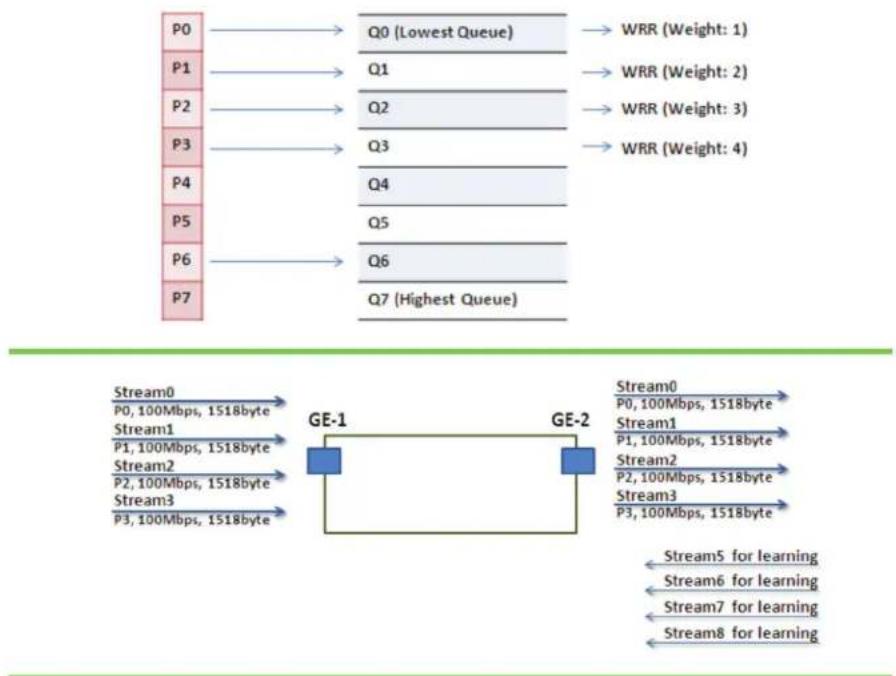
flowchart
graph TD
    subgraph Stream0
        P0 --> Q0["Q0 (Lowest Queue)"]
        P1 --> Q1
        P2 --> Q2
        P3 --> Q3
        P4 --> Q4
        P5 --> Q5
        P6 --> Q6
        P7 --> Q7["Highest Queue"]
    end

    subgraph Stream1
        GE1["GE-1"]
        GE2["GE-2"]
    end

    subgraph Stream2
        GE1
        GE2
    end

    subgraph Stream3
        GE1
        GE2
    end

    subgraph Stream5
        Stream5 -->|for learning| Stream6["Stream6 for learning"]
        Stream7["Stream7 for learning"] -->|for learning| Stream8["Stream8 for learning"]
    end

    P0 --> Q0
    P1 --> Q1
    P2 --> Q2
    P3 --> Q3
    P4 --> Q4
    P5 --> Q5
    P6 --> Q6
    P7 --> Q7

    Q0 --> WRR1["WRR (Weight: 1)"]
    Q1 --> WRR2["WRR (Weight: 2)"]
    Q2 --> WRR3["WRR (Weight: 3)"]
    Q3 --> WRR4["WRR (Weight: 4)"]

    GE1 --> GE2
    GE2 --> Stream5
Figure 4-64.
- Stream 0:
Dst Mac: 00:00:00:00:20:01
Src Mac: 00:00:00:00:10:01
Vlan: 100
Vlan prio: 0
Send rate: 100 Mbps
Packet length: 1518 bytes
-
Stream 1: Dst Mac: 00:00:00:00:20:02
Src Mac: 00:00:00:00:10:02
Vlan: 100
Vlan prio: 3
Send rate: 100 Mbps
Packet length: 1518 bytes -
Stream 2: Dst Mac: 00:00:00:00:20:03
Src Mac: 00:00:00:00:10:03
Vlan: 100
Vlan prio: 7
Send rate: 100 Mbps
Packet length: 1518 bytes -
Stream 3: Dst Mac: 00:00:00:00:20:04
Src Mac: 00:00:00:00:10:04
Vlan: 100
Vlan prio: 7
Send rate: 100 Mbps
Packet length: 1518 bytes -
Stream 5: (for Learning) Dst Mac: 00:00:00:00:10:01
Src Mac: 00:00:00:00:20:01
Vlan: 100
Vlan prio: 0
Send rate: 10 Mbps
Packet length: 1518 bytes -
Stream 6: (for Learning) Dst Mac: 00:00:00:00:10:02
Src Mac: 00:00:00:00:20:02
Vlan: 100
Vlan prio: 0
Send rate: 10 Mbps
Packet length: 1518 bytes -
Stream 7: (for Learning) Dst Mac: 00:00:00:00:10:03
Src Mac: 00:00:00:00:20:03
Vlan: 100
Vlan prio: 0
Send rate: 10Mbps
Packet length: 1518 bytes
- Stream 8: (for Learning)
Dst Mac: 00:00:00:00:10:04
Src Mac: 00:00:00:00:20:04
Vlan: 100
Vlan prio: 0
Send rate: 10Mbps
Packet length: 1518 bytes
Web management:
STEP 1: Go to Configuration—> Qos —> Port shaping, and click on PORT-2 to create a Qos profile.
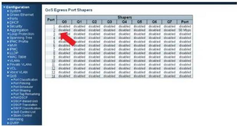
Figure 4-65.
STEP 2: Select schedule mode to “Weighted” and set the weight value for queue 0, and set weight value for queue 0–queue 3 as described next.
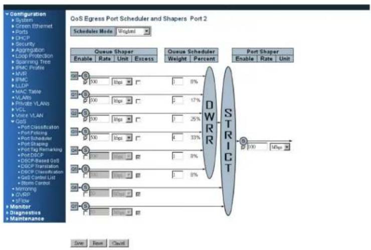
flowchart
graph TD
    A["QoS Egress Port Scheduler and Shapers Port 2"] --> B["Scheduler Mode: Wugland"]
    B --> C["Queue Shaper"]
    C --> D["Enable Rate Unit Excess"]
    C --> E["Queue Scheduler Weight Percent"]
    E --> F["Port Shaper"]
    F --> G["Enable Rate Unit"]
    F --> H["WR Strict"]
    H --> I["100 Mbps"]
    style A fill:#f9f,stroke:#333
    style B fill:#ccf,stroke:#333
    style C fill:#cfc,stroke:#333
    style D fill:#fcc,stroke:#333
    style E fill:#cff,stroke:#333
    style F fill:#ffc,stroke:#333
    style G fill:#fcc,stroke:#333
    style H fill:#ffc,stroke:#333
    style I fill:#fcc,stroke:#333
Figure 4-66.
STEP 3: Go to Configuration—> Queue and Scheduler —> Binding, and bind profile 2 on Port 2.
CLI configuration commands:
interface GigabitEthernet 1/2
switchport trunk allowed vlan 1,100
switchport hybrid allowed vlan 100,4095
switchport trunk vlan tag native
switchport mode trunk
qos shaper 100000
qos queue-shaper queue 0 500
qos queue-shaper queue 1 500
qos queue-shaper queue 2 500
qos queue-shaper queue 3 500
qos wrr 1 2 3 4 1 1
exit
Case 2:
Gigabit port VLAN Priority & Queue mapping
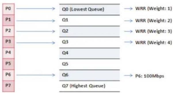
flowchart
graph LR
    P0 --> Q0["Q0 (Lowest Queue)"]
    P1 --> Q1
    P2 --> Q2
    P3 --> Q3
    P4 --> Q4
    P5 --> Q5
    P6 --> Q6
    P7 --> Q7["Highest Queue"]
    Q0 --> WRR1["WRR (Weight: 1)"]
    Q1 --> WRR2["WRR (Weight: 2)"]
    Q2 --> WRR3["WRR (Weight: 3)"]
    Q3 --> WRR4["WRR (Weight: 4)"]
    Q4 --> P6["P6: 100Mbps"]
    Q5 --> P6
    Q6 --> P6
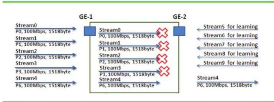
flowchart
graph LR
    A["Stream0\nP0, 100Mbps, 1518byte"] --> B["GE-1"]
    C["Stream1\nP1, 100Mbps, 1518byte"] --> B
    D["Stream2\nP2, 100Mbps, 1518byte"] --> B
    E["Stream3\nP3, 100Mbps, 1518byte"] --> B
    F["Stream4\nP6, 100Mbps, 1518byte"] --> B
    B --> G["GE-2"]
    H["Stream0\nP0, 100Mbps, 1518byte"] --> I["GE-2"]
    J["Stream1\nP1, 100Mbps, 1518byte"] --> I
    K["Stream2\nP2, 100Mbps, 1518byte"] --> I
    L["Stream3\nP3, 100Mbps, 1518byte"] --> I
    M["Stream4\nP6, 100Mbps, 1518byte"] --> I
    I --> N["Stream5 for learning"]
    I --> O["Stream6 for learning"]
    I --> P["Stream7 for learning"]
    I --> Q["Stream8 for learning"]
    I --> R["Stream9 for learning"]
    I --> S["Stream4\nP6, 100Mbps, 1518byte"]
Figure 4-67.
- Stream 0:
Dst Mac: 00:00:00:00:20:01
Src Mac: 00:00:00:00:10:01
Vlan: 100
Vlan prio: 0
Send rate: 100 Mbps
Packet length: 1518 bytes
- Stream 1:
Dst Mac : 00:00:00:00:20:02
Src Mac : 00:00:00:00:10:02
Vlan : 100
Vlan prio : 3
Send rate : 100Mbps
Packet length: 1518bytes
- Stream 2:
Dst Mac: 00:00:00:00:20:03
Src Mac: 00:00:00:00:10:03
Vlan: 100
Vlan prio: 7
Send rate: 100 Mbps
Packet length: 1518 bytes
- Stream 3:
Dst Mac: 00:00:00:00:20:04
Src Mac: 00:00:00:00:10:04
Vlan: 100
Vlan prio: 7
Send rate: 100 Mbps
Packet length: 1518 bytes
- Stream 4:
Dst Mac: 00:00:00:00:20:07
Src Mac: 00:00:00:00:10:07
Vlan: 100
Vlan prio: 7
Send rate: 100 Mbps
Packet length: 1518 bytes
- Stream 5: (for Learning)
Dst Mac: 00:00:00:00:10:01
Src Mac: 00:00:00:00:20:01
Vlan: 100
Vlan prio: 0
Send rate: 10 Mbps
Packet length: 1518 bytes
- Stream 6: (for Learning)
Dst Mac: 00:00:00:00:10:02
Src Mac: 00:00:00:00:20:02
Vlan: 100
Vlan prio: 0
Send rate: 10 Mbps
Packet length: 1518 bytes
-
Stream 7: (for Learning)
Dst Mac: 00:00:00:00:10:03
Src Mac: 00:00:00:00:20:03
Vlan: 100
Vlan prio: 0
Send rate: 10 Mbps
Packet length: 1518 bytes -
Stream 8: (for Learning)
Dst Mac: 00:00:00:00:10:04
Src Mac: 00:00:00:00:20:04
Vlan: 100
Vlan prio: 0
Send rate: 10 Mbps
Packet length: 1518 bytes -
Stream 9: (for Learning)
Dst Mac: 00:00:00:00:10:07
Src Mac: 00:00:00:00:20:07
Vlan: 100
Vlan prio: 0
Send rate: 10Mbps
Packet length: 1518 bytes
Web management:
STEP 1: Go to Configuration —> Qos —> Port shaping, and click on Port 2 to create a Qos profile.
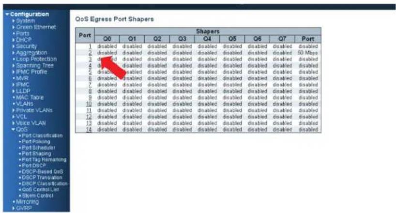
Figure 4-68.
STEP 2: Select schedule mode to ""Weighted" and set the weight value for queue 0, and set weight value for queue 0–queue 3 as described next.
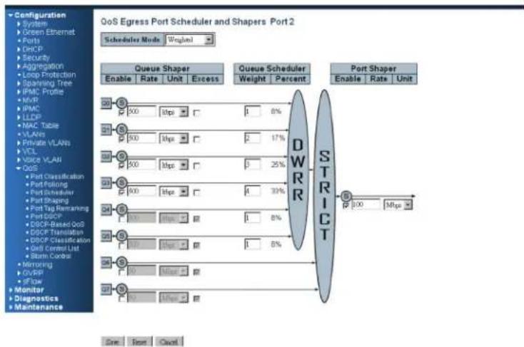
flowchart
graph TD
    A["Queue Shaper"] --> B["Enable Rate Unit Excess"]
    C["Queue Scheduler"] --> D["Weight Percent"]
    E["Port Shaper"] --> F["Enable Rate Unit"]
    G["DWR"] --> H["Strict"]
    I["STRICT"] --> J["100 Mbps"]
    K["Queue Shaper"] --> L["500 Mbps"]
    M["Queue Shaper"] --> N["500 Mbps"]
    O["Queue Shaper"] --> P["500 Mbps"]
    Q["Queue Shaper"] --> R["500 Mbps"]
    S["Queue Shaper"] --> T["500 Mbps"]
    U["Queue Shaper"] --> V["500 Mbps"]
    W["Queue Shaper"] --> X["500 Mbps"]
    Y["Queue Shaper"] --> Z["500 Mbps"]
    AA["Queue Shaper"] --> AB["500 Mbps"]
    AC["Queue Shaper"] --> AD["500 Mbps"]
    AE["Queue Shaper"] --> AF["500 Mbps"]
    AG["Queue Shaper"] --> AH["500 Mbps"]
    AI["Queue Shaper"] --> AJ["500 Mbps"]
    AK["Queue Shaper"] --> AL["500 Mbps"]
    AM["Queue Shaper"] --> AN["500 Mbps"]
    AO["Queue Shaper"] --> AP["500 Mbps"]
    AQ["Queue Shaper"] --> AR["500 Mbps"]
    AS["Queue Shaper"] --> AT["500 Mbps"]
    AU["Queue Shaper"] --> AV["500 Mbps"]
    AW["Queue Shaper"] --> AX["500 Mbps"]
    AY["Port Classification"] --> AZ["Port Splicing"]
    BA["Port Scheduling"] --> BB["Port Shaping"]
    BC["Port Tag Remarking"] --> BD["Port DISCP"]
    BE["DSCP-Based QoB"] --> BF["DSCP Translation"]
    BG["DSCP Classification"] --> BH["Grid Control List"]
    BI["SMA Control"] --> BJ["SMA Control"]
    BK["Mirroring"] --> BL["Mirroring"]
    BM["GVRR"] --> BN["GVRR"]
    BO["SFGW"] --> BP["SFGW"]
    BQ["Monitor"] --> BR["Monitor"]
    BS["Diagnostics"] --> BT["Diagnostics"]
    BU["Maintenance"] --> BV["Maintenance"]
Figure 4-69.
CLI configuration command:
interface GigabitEthernet 1/2
switchport trunk allowed vlan 1,100
switchport hybrid allowed vlan 100,4095
switchport trunk vlan tag native
switchport mode trunk
qos shaper 100000
qos wrr 1 2 3 4 1 1
exit
4.7 IGMP Application Guide
4.7.1 Explanation of IGMP
IGMP is an acronym for Internet Group Management Protocol. It is a communications protocol used to manage the membership of Internet Protocol multicast groups. IGMP is used by IP hosts and adjacent multicast routers to establish multicast group memberships. It is an integral part of the IP multicast specification, similar to ICMP for unicast connections. IGMP can be used for online video and gaming, and allows more efficient use of resources when supporting these uses.
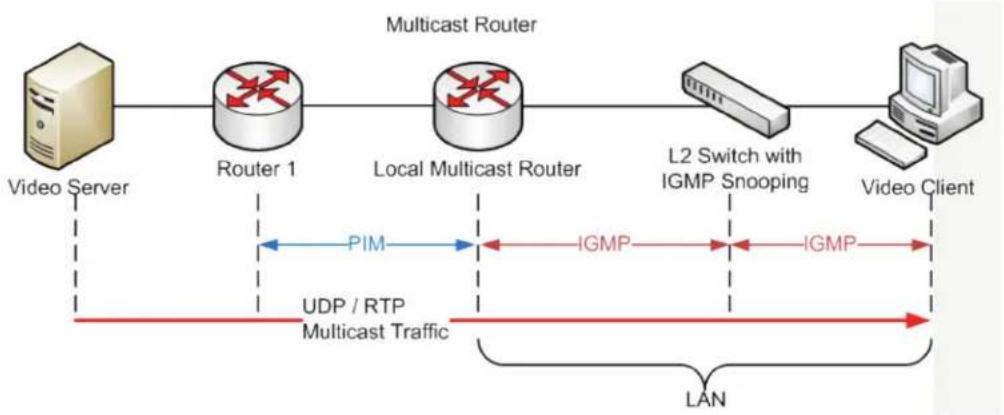
flowchart
graph LR
    A["Video Server"] --> B["Router 1"]
    B --> C["Local Multicast Router"]
    C --> D["L2 Switch with IGMP Snooping"]
    D --> E["Video Client"]
    F["UDP / RTP Multicast Traffic"] --> C
    G["PIM"] --> C
    H["IGMP"] --> C
    I["IGMP"] --> D
    J["LAN"] --> E
Figure 4-70.
Example 1:
The administrator can set every client to get the multicast stream. Go to "Configuration—>IPMC—>Basic Configuration" and select the "Snooping Enable" checkbox, and click on OK.
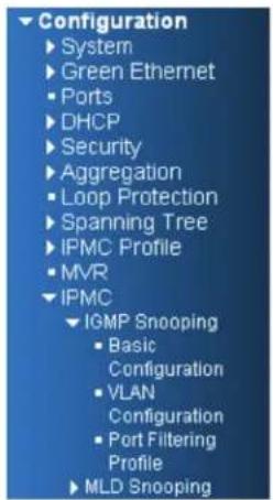
IGMP Snooping Configuration
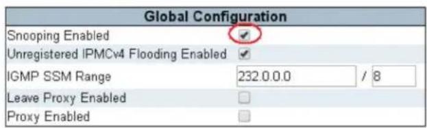
Port Related Configuration
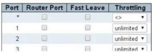
Figure 4-71.
Example 2:
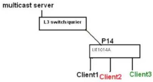
flowchart
graph TD
    A["multicast server"] --> B["L3 switch/currier"]
    B --> C["P14"]
    C --> D["LIF1014A"]
    D --> E["Client1"]
    D --> F["Client2"]
    D --> G["Client3"]
Figure 4-72.
- Go to "Configuration—>IPMC—>Basic Configuration" to select the "Snooping Enable" checkbox
- De-select the "Unregistered IPMCv4 Flooding Enabled" checkbox.
- If the Multicast stream is from an L3 switch, then the uplink port must be "Router Port."
NOTE: If an aggregation member port is selected as a router port, the whole aggregation will act as a router port.
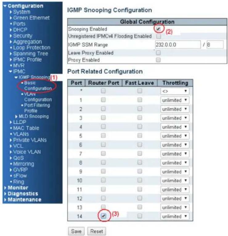
Figure 4-73.
- Go to "Configuration—>IPMC—>VLAN Configuration" to select the "Snooping Enable" checkbox and set Port 14's VLAN ID.
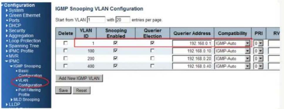
Figure 4-74.
Example 3:
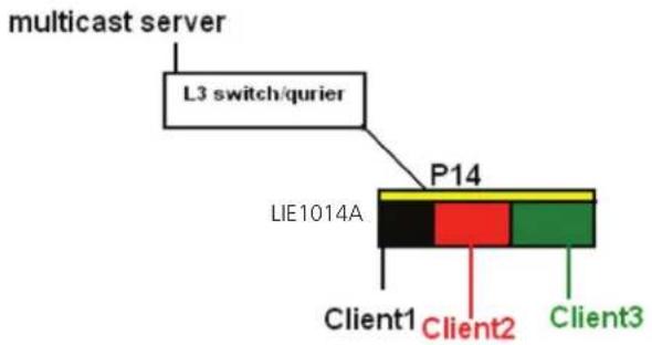
Figure 4-75.
In this scenario, these clients belong to multiple vlans, so you have to create more than one vlan to be the agent for all client vlans.
- To create a vlan: go to "Configuration—>VLANs—>Allow Access VLANs", then set port 14 to be the vlan200 member port.
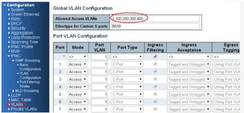
Figure 4-76.
- Go to "Configuration—>IPMC—>VLAN Configuration" to select the "Snooping Enable" checkbox and set Port 14's VLAN ID.
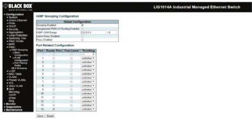
Figure 4-77.
-
If there is no querier on the L3 switch, select "Querier Election," and set the "Querier Address." The IP address is in the same network as the uplink interface.
-
Select the IGMP version as the server.

Figure 4-78.
4.7.2 Configuring VLC on an IGMP Server
- In the Media area of the top tool bar, select "Stream."
natural_image
3D cone-shaped object displayed in a video player interface (no text or symbols on the object itself)Figure 4-79.
- Select a video or voice file to play.
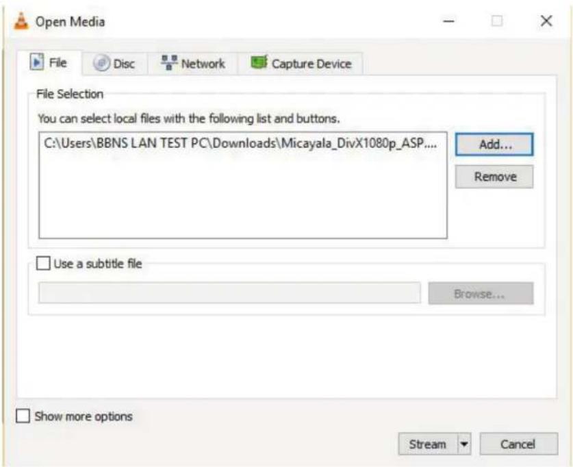
Figure 4-80.
- Confirm that the file is correct, then click "Next" twice.
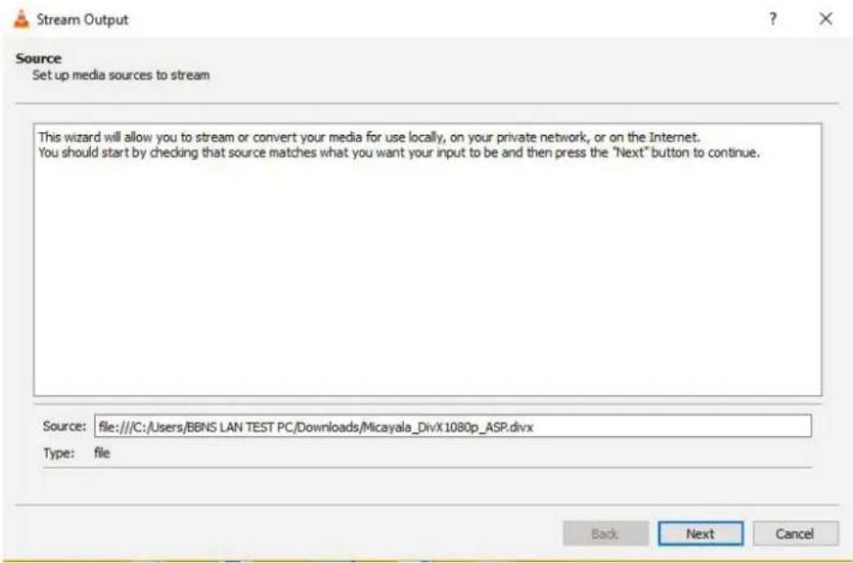
Figure 4-81.
- Select the stream type as "UDP" and click the "Add" button.
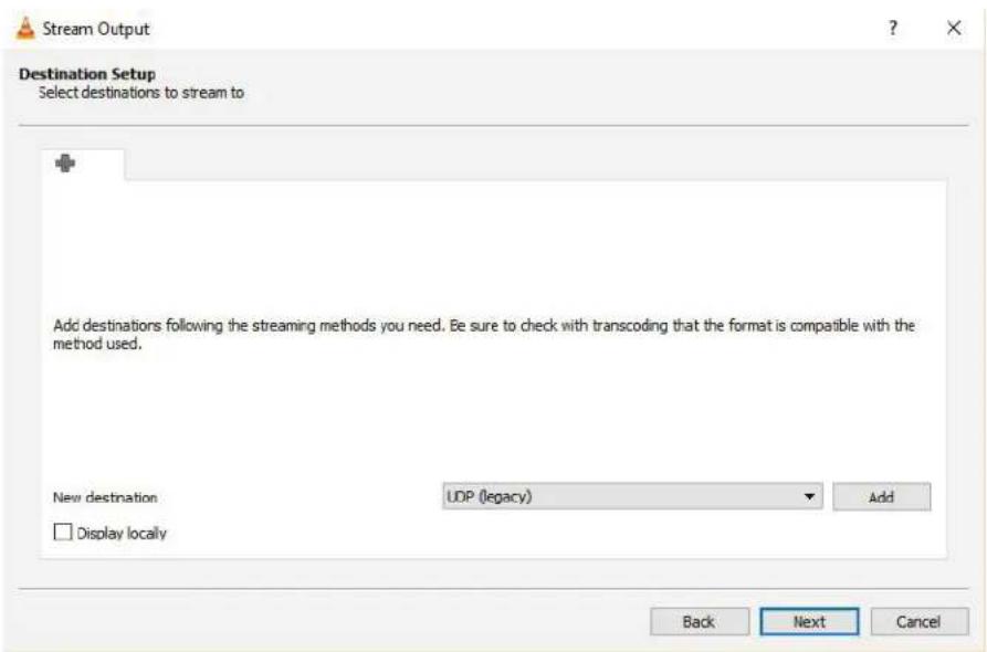
Figure 4-82.
- Set the stream IP; the range is 224.0.0.1 to 239.255.255.254, and the protocol port is 1234.
For this example, we set stream IP as 255.0.0.1.
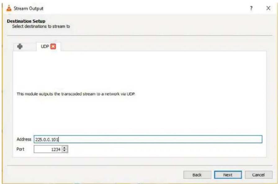
Figure 4-83.
- Select "Sort out all stream" and click the "Stream" button, then the stream starts sending to switch.
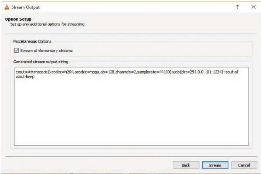
Figure 4-84.
4.7.3 Configuring VLC on an IGMP Client
- In the Media area of the top tool bar, select Open Network Stream.
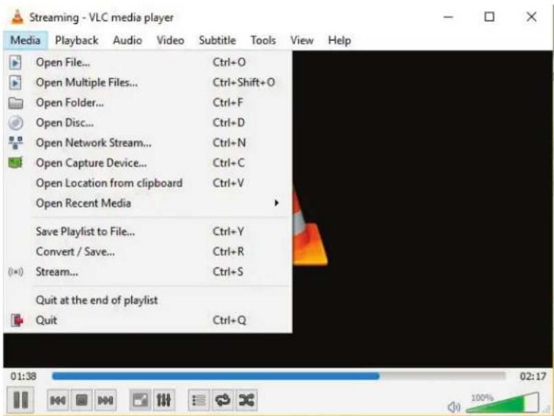
Figure 4-85.
- Set the stream IP and protocol port as the previous setting on the server. The protocol type is "UDP," and the format should be the same as below the circle, then click the "PLAY" button.
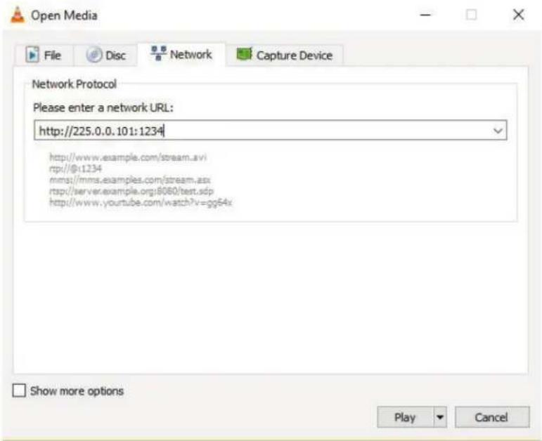
Figure 4-86.
To return to the management switch:
Go to "Monitor—>IPMC—>Groups Information," and you will see the IP stream in the table.
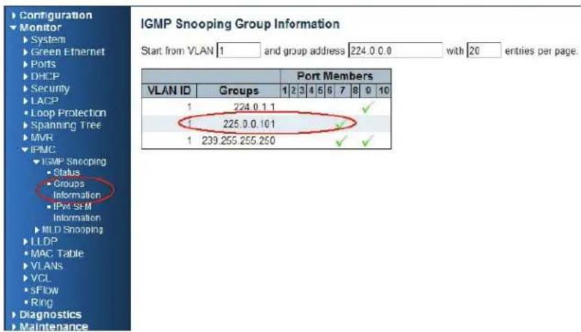
Figure 4-87.
4.8 802.1x Authentication Application Guide
4.8.1 Explanation of 802.1x Authentication
IEEE 802.1x derives keys that you can use to provide per-packet authentication, integrity, and confidentially. Typically, you would use the keys along with well-known key derivation algorithms (e.g., TLS, SRP, MD5-Challenge, etc.). The LIG1014A/LIE1014A switch supports the 802.1x authentication function per port (Port 1–Port 10). Enable the system's 802.1x function, then choose the ports and type you want to apply. If you enable 802.1x authentication control for a certain Ethernet port on the switch, this port should be authenticated before using any service from the network.
4.8.2 802.1x Timer in the Industrial Managed Gigabit Ethernet Switch
Table 4-3. 802.1x Timer in the LIG1014A/LIE1014A switch.
| Item | Parameter (sec) | Description |
| 1 | ReAuth Period | LIG1014A/LIE1014A will restart authentication after each Reauth-Period when authentication is successful and the ReAuth option is enabled. |
| 2 | Quiet Period | LIG1014A/LIE1014A will wait the length of the QuietPeriod to restart the authentication process again when authentication failed the previous time. |
| 3 | Tx Period | LIG1014A/LIE1014A will send the EAP-request to the Supplicant every TxPeriod when authentication is running and the Quiet Period is not running. |
| 4 | Supplicant Timeout | LIG1014A/LIE1014A will wait the length of the SupplicantTimeout to receive a response from the Supplicant. |
5 Server Timeout LIG1014A/LIE1014A will wait ServerTimeout to receive response from RADIUS server.
4.8.3 Configuration in a RADIUS Server
STEP 1: Prepare a Linux PC with a RADIUS server installed.
STEP 2: Edit the secret key for the Radius server.
Setting:
client 20.20.20.0/24 {
secret = a1b2c3d4
STEP 3: Edit the user name and password for supplicant to authenticate with the server.
Setting:
test123 Cleartext-Password := "test123"
aaaa Cleartext-Password := "aaaa"
STEP 4: Set a static IP address for this Radius Server.
Setting: 20.20.20.20
STEP 5: Start Radius Server
Example:
To learn how to activate 802.1x Authentication via LIG1014A/LIE1014A to be authenticated by a RADIUS server, read the following example. In this basic example, Port 1 is a testing port that enables 802.1x in the LIG1014A/LIE1014A.
With the default configuration, use the following Web UI setting:
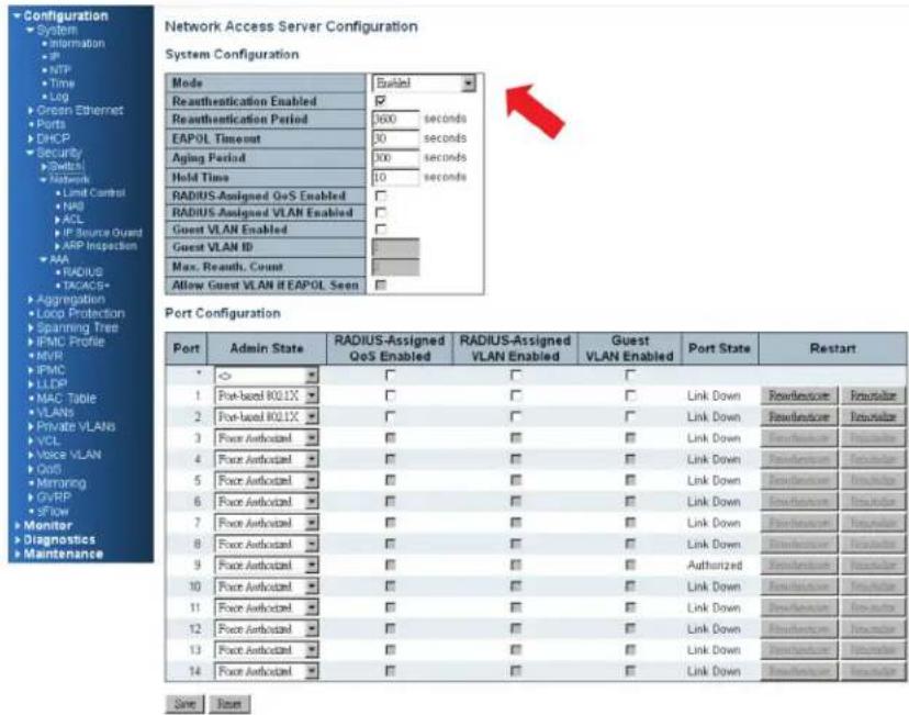
Figure 4-88.
STEP 5A: Go to Configuration—> Security —> Networks —> NAS.
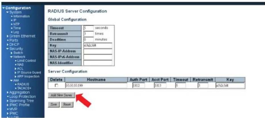
Figure 4-89.
Select "Enable" to enable authentication, and set Port 1 and Port 2 as "Port Base 802.1x."
STEP 5B: Go to Configuration → Security → AAA → Radius.
Click "Add New Server," and type in "20.20.20.20" for the server, and "a1b2c3d4" for the secret key. Then click the "Save" button.
CLI Command:
Configure ter
interface vlan 1
ip address 20.20.20.120 255.0.0.0
exit
exit
radius-server host 20.20.20.20 timeout 5 retransmit 3 key a1b2c3d4
dot1x re-authentication
dot1x system-auth-control
interface GigabitEthernet 1/1
dot1x port-control auto
Configuration
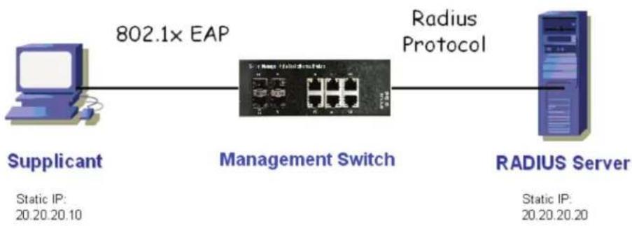
flowchart
graph LR
    A["Supplicant"] -->|802.1x EAP| B["Management Switch"]
    B --> C["RADIUS Server"]
    style A fill:#f9f,stroke:#333
    style B fill:#ccf,stroke:#333
    style C fill:#cfc,stroke:#333
Figure 4-90.
Supplicant's NIC Setting
STEP 5C: Configure a static IP address 20.20.20.10 and a net mask 255.255.255.0 for the supplicant.
(If a DHCP server will assign an IP address for supplicant, you can ignore this step.)
STEP 5D: Select the IEE E802.1x Authentication Enable check box, then configure the EAP type as MD5-Challenge.
After setting this function in the NIC, the supplicant should enter a correct pair of account and password to use this Ethernet port service from the LIG1014A/LIE1014A.
Authentication Behavior
The supplicant should pass authentication process to use any service. After the supplicant enters the correct account and password stored in RADIUS server, it can be authenticated successfully. The authentication process is described in the following diagram.
UE1014A
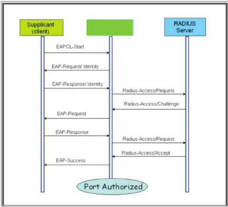
flowchart
graph TD
    A["Supplicant (client)"] -->|EAPOL-Start| B["Port Authorized"]
    B -->|EAP-Request/Identity| A
    A -->|EAP-Response/Identity| B
    B -->|EAP-Request| A
    A -->|EAP-Response| B
    B -->|EAP-Success| A
    B -->|Radius-Access/Request| C["RADIUS Server"]
    C -->|Radius-Access/Challenge| B
    B -->|Radius-Access/Request| C
    C -->|Radius-Access/Accept| B
Figure 4-91.
5. Hardware Quick Setup Guide
5.1 What's Included
Your package should contain the following items. If anything is missing or damaged, contact Black Box Technical Support at 877-877-2269 or info@blackbox.com.
• (1) Industrial Managed Gigabit Ethernet Switch - (10) RJ-45, (4) SFP (LIG1014A)
OR
(1) Industrial Managed Gigabit Ethernet PoE+ Switch - (8) RJ-45, (4) SFP (LIE1014A)
• (2) wallmount brackets
• (1) DIN-rail clip
• (4) M3 screws (for the wallmount brackets or DIN-rail clip)
• (1) DC power terminal block
• (10) or (8) RJ-45 connector dust covers
• (4) SFP port dust covers
• This Quick Start Guide
WARNING! When a connector is removed during installation, testing, or servicing, or when an energized fiber is broken, your eyes might be exposed to to hazardous laser output power.
5.2 Mounting the Switch on a DIN Rail
- Screw the DIN rail bracket onto the switch with the included bracket and screws.
- Hook the switch-DIN-rail-bracket assembly over the DIN rail.
- Push the bottom of the assembly towards the DIN rail until it snaps into place.
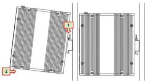
Figure 5-1. Din-rail mounting.
5.3 Mounting the Switch on a Wall
Screw the wall mount brackets on using the included M3 screws.
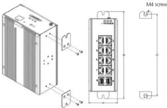
Figure 5-2. Wallmounting.
5.4 Ethernet Interface
The switch has two types of Ethernet interfaces: electrical (RJ-45) and optical (SFP) interfaces.
5.4.1 RJ-45
• To connect the switch to a PC, use straight-through or cross-over Ethernet cables.
• To connect the switch to an Ethernet device, use UTP (Unshielded Twisted Pair) or STP (Shielded Twisted Pair) Ethernet cables.
The RJ-45 pinout is shown in the following figure and tables.
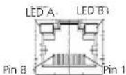
Figure 5-3. RJ-45 connector pinout.
Table 5-1. RJ-45 pinout descriptions
| Pin Assignment PoE Assignment (LIE1014A only) | |
| 1, 2 TX/RX+, TX/RX- Positive V port | |
| 3, 6 TX/RX+, TX/RX- Negative V port | |
| 4, 5 TX/RX+, TX/RX- Not used | |
| 7,8 TX/RX+, TX/RX- Not used |
5.4.2 Fiber, SFP
For both 100/1000 Mbps fiber speed connections, the SFP slots are available. The SFP slot accepts the fiber transceivers that typically have an LC connector.
The fiber transceivers have options of multimode, single mode, long-haul or special application transceivers.
DANGER:
Never attempt to view optical connectors that might be emitting laser energy.
Do not power up the laser product without connecting the laser to the optical fiber and putting the dust cover in position, because laser outputs will emit infrared laser light at this point.
Table 5-2. Compatible SFP modules.
| PartNumber Description |
| LFP411 SFP/1250 Extended Diagnostics, LC multimode, 850 nm, 550 m |
| LFP412 SFP/1250 Extended Diagnostics, LC multimode, 1310 nm, 2 km |
| LFP413 SFP/1250 Extended Diagnostics, LC single-mode, 1310 nm, 10 km |
| LFP414 SFP/1250 Extended Diagnostics, LC single-mode, 1310 nm, 40 km |
| LFP401 SFP/155 Extended Diagnostics, LC multimode, 850 nm, 2 km |
| LFP403 SFP/155 Extended Diagnostics, LC single-mode, 1310 nm, 30 km |
| LFP404 SFP/155 Extended Diagnostics, LC single-mode, 1310 nm, 60 km |
| LFP402 SFP/155 Extended Diagnostics, LC multimode, 1310 nm, 2 km |
| LFP418 SFP/1250 Extended Diagnostics, LC single-mode, 1550 nm, 80 km |
| LFP420 Simplex SFP/1250, Extended Diagnostics, single-mode, 1550 nm TX, 1310 nm RX |
5.5 Connecting the Power Terminal Block
The switch can be powered from two power supplies (input range 12V – 58V). Insert the positive and negative wires into V+ and V- contacts on the terminal block respectively and tighten the wire-clamp screws to prevent the wires from loosening.
UG1014A
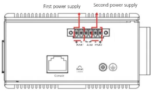
Figure 5-4. Terminal block, LIG1014A.
UE1014A
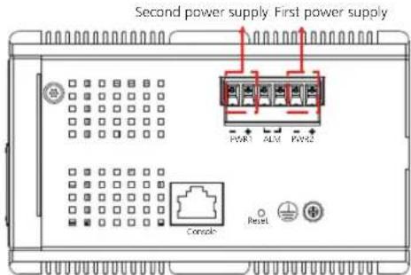
Figure 5-5. Terminal block, LIE1014A.
5.6 Alarm Relay and Ground
The alarm relay output contacts are in the middle of the DC terminal block connector as shown in the figure below.
The alarm relay out is "Normal Open", and it will be closed when detected any predefined failure such as power failures or Ethernet link failures.
The relay output has current carrying capacity of 0.5 A @ 24 VDC.
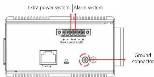
Figure 5-6. Alarm relay, LIG1014A or LIE1014A.
5.7 Console Connection
The Console port is for local management by using a terminal emulator or a computer with terminal emulation software.
- DB9 connector connect to computer COM port
• Baud rate: 115200bps - 8 data bits, 1 stop bit
- No Priority
- No flow control
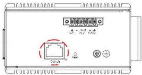
Figure 5-7. Console connector, LIG1014A or LIE1014A.
An RJ-45 (male) connector-to-RS-232 DB9 (female) connector cable is required. The RJ-45 connector of the cable is connected to the console connector on the switch. The pin assignment of the console cable is shown on the next page.
5.8 Connect and Login to Managed Switch
- Connecting to the Ethernet port (RJ45 Ethernet port) of Managed Switch.
- Factory default IP: 192.0.2.1
- Login with default account and password.
Username: admin
Password: (none)
5.9 CLI Initialization and Configuration (Optional)
- Connecting to the Ethernet port(RJ45 Ethernet port) of Managed Switch
- Type in the command under Telnet: telnet 192.0.2.1
- Login with the default account and password.
Username: admin
Password: (none)
- Change the IP with commands listed below:
CLI Command:
enable
configure terminal
interface vlan 1
ip address xxx.xxx.xxx.xxx.xxx.xxx.xxx
exit
5.10 Indicators
Table 5-3. Front-panel LEDs on the LIG1014A.
| LED Name Status Condition | ||
| (1) P1 LED ON, Green P1 power line | has power | |
| OFF P1 power line is disconnected or does not have power | ||
| (1) P2 LED ON, Green P2 power line | has power | |
| OFF P2 power line is disconnected or does not have power | ||
| (1) Alarm LED ON, Red Failure alarm | occurs | |
| OFF No power failure alarm | ||
| (10) Link/Act LEDs for RJ-45 ports | On, Green | Ethernet link is up but no traffic is detected |
| OFF Ethernet link is down | ||
| (10) Speed LEDs for RJ-45 ports | ON, Yellow | 1000-Mbps connection is detected. |
| OFF No link, a 10-Mbps or 100-Mbps connection is detected | ||
| (4) Link/Act LED for SFP port ON, Green Ethernet link is up | ||
| (4) Speed LED for SFP port | ON, Yellow | SFP port speed 1000-Mbps connection is detected |
| OFF No link, or an SFP port speed 100-Mbps connection is detected | ||
Table 5-4. Front-panel LEDs on the LIE1014A.
| LED Name Status Condition | ||
| (8) PoE LEDs ON, Green PoE is working | ||
| OFF PoE is not working | ||
| (1) P1 LED ON, Green P1 power line has power | ||
| OFF P1 power line is disconnected or does not have power | ||
| (1) P2 LED ON, Green P2 power line has power | ||
| OFF P2 power line is disconnected or does not have power | ||
| (1) Alarm LED ON, Red Power failure alarm occurs | ||
| OFF No power failure alarm | ||
| (8) Link/Act LEDs for RJ-45 PoE+ ports | On, Green | Ethernet link is up but no traffic is detected |
| OFF Ethernet link is down | ||
| (8) Speed LEDs for RJ-45 PoE+ ports | ON, Yellow | 1000-Mbps connection is detected. |
| OFF No link, a 10-Mbps or 100-Mbps connection is detected | ||
| (4) Link/Act LED for SFP port ON, Green Ethernet link is up | ||
| OFF Ethernet link is down | ||
| (4) Speed LED for SFP port | ON, Yellow | SFP port speed 1000-Mbps connection is detected |
| OFF No link, or an SFP port speed 100-Mbps connection is detected | ||
Black Box Tech Support: FREE! Live. 24/7.
Tech support the way it should be.

natural_image
Close-up portrait of a smiling man holding a small object, against a blue gradient background (no text or symbols visible)Great tech support is just 60 seconds away at 877-877-2269 or blackbox.com.

BLACK BOX®
About Black Box
Black Box provides an extensive range of networking and infrastructure products. You'll find everything from cabinets and racks and power and surge protection products to media converters and Ethernet switches all supported by free, live 24/7 Tech support available in 60 seconds or less.
© Copyright 2016. Black Box Corporation. All rights reserved. Black Box ^® and the Double Diamond logo are registered trademarks of BB Technologies, Inc. Any third-party trademarks appearing in this manual are acknowledged to be the property of their respective owners.
lig1014a_lie1014a_user_rev3
- Industrial Managed Gigabit Ethernet Switch
- User Manual
- Trademarks Used in this Manual
- Federal Communications Commission and Industry Canada Radio Frequency Interference Statements
- Quick Study: Condensed Explanation of Terms Used in this Manual
- Table of Contents
- Overview
- Introduction
- Power over Ethernet
- Multi-rate SFP slots
- Power
- Extended temperature range
- Management
- Features
- What's Included
- LIG1014A:
- LIE1014A:
- Additional Items You Will Need
- Hardware Description LIG1014A
- Connecting to Your Industrial Managed Gigabit Ethernet Switch
- Connecting to Your Switch via a Serial Console
- Connecting to the Switch via Telnet
- Connecting to the Switch via a Web Browser
- Switch Functions
- VLAN Application Guide
- Explanation of VLAN (Virtual LAN)
- Example 1: Default VLAN Settings
- Example 2: Port-based VLANs
- CLI Commands
- Example 3: IEEE 802.1Q Tagging
- Configuration:
- CLI Command:
- Security Application Guide
- Explanation of ACL (Access Control List)
- Case 1: ACL for MAC address
- CLI Commands:
- Case 2: ACL for IP address
- Case 3: ACL for L4 Port
- Case 4: ACL for ToS
- Ring Protection Application Guide
- Explanation of Ring Protection
- Configuration (Console)
- Configuration (Web UI)
- Dual Ring
- Configure Steps:
- NOTE: Rules:
- Configure ring protection on the middle ring group (ring2).
- On device 2 and 7 (master):
- On device 1 and 8 (slave):
- On device 3–6 (slave) + Inter-connection:
- Dual Homing
- On device 5 (slave):
- On device 6 (slave):
- Ring Version 2 Feature
- Explanation of Ring Version 2
- Group 1: Supports ring-master and ring-slave options
- Group 2: Supports ring, coupling, and dual-homing configurations
- Group 3: This supports chain and balancing-chain configurations
- NOTES:
- Configuring Ringv2
- Configuration (Console)
- Configuration (Web UI)
- Disable RSTP on All Ring Ports
- Configuration (Ring Master)
- Ring Slave
- Coupling Primary
- Coupling Backup
- Dual-Homing
- Chain(Member)
- Chain(Head)
- Chain(Tail)
- Balance Chain(Central Block)
- Balance Chain(Terminal)
- QoS Application Guide
- Explanation of QoS
- SP/SPWRR/WRR
- Application Examples
- Example 1: SPQ without Shaping (Default profile)
- Example 2: SPQ with Shaping
- Example 3: WRR
- Web management:
- Example 4 SP-WRR
- IGMP Application Guide
- Explanation of IGMP
- Example 1:
- Configuring VLC on an IGMP Server
- Configuring VLC on an IGMP Client
- 802.1x Authentication Application Guide
- Explanation of 802.1x Authentication
- 802.1x Timer in the Industrial Managed Gigabit Ethernet Switch
- Configuration in a RADIUS Server
- STEP 5: Start Radius Server
- Configuration
- Authentication Behavior
- Hardware Quick Setup Guide
- What's Included
- Mounting the Switch on a DIN Rail
- Mounting the Switch on a Wall
- Ethernet Interface
- RJ-45
- Fiber, SFP
- DANGER:
- Connecting the Power Terminal Block
- UG1014A
- Alarm Relay and Ground
- Console Connection
- Connect and Login to Managed Switch
- CLI Initialization and Configuration (Optional)
- Indicators
- Black Box Tech Support: FREE! Live. 24/7.
- BLACK BOX®
- About Black Box
Brand : Black Box
Model : LIE1014A
Category : Switch