
Furious Three RG - Uncategorized Eliminator Lighting - Free user manual and instructions
Find the device manual for free Furious Three RG Eliminator Lighting in PDF.


| Product Type | 3-in-1 Dance Party Lighting Effect (Moonflower, Wash, Laser) |
| LED Moonflower | 5 x 3W RGBWY 5-in-1 LEDs |
| Wash LEDs | 6 x 3W RGBY Quad LEDs |
| Laser Diodes | Red & Green (Class 3R) |
| Control Modes | DMX, Sound Active, Auto, Primary/Secondary |
| DMX Channels | 9 |
| DMX Connectors | 3-pin XLR In/Out |
| Power Connectors | IEC AC In/Out (daisy chain) |
| Power Consumption | 40W max |
| Fuse | F2A 250V (replaceable) |
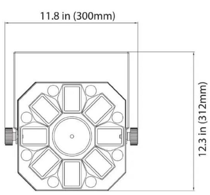
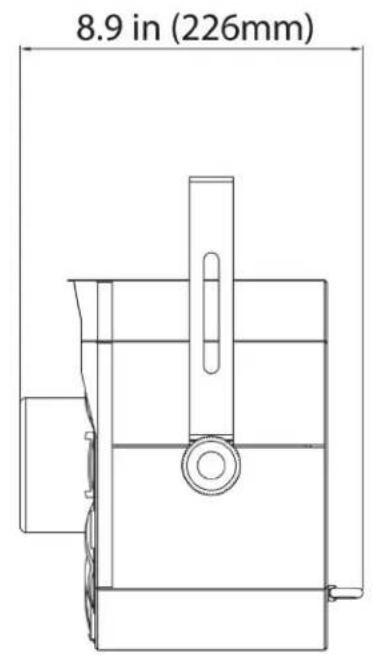
| Dimensions (L x W x H) | 11.8 x 12.25 x 8.9 inches / 300 x 312 x 226 mm |
| Weight | 8 lbs / 3.7 kg |
| Dimmer | Electronic 0-100% |
| Strobe | LED and Laser strobe with speed control |
| Laser Safety | Safety key switch, safety eye on rear panel |
| Microphone | Built-in with sensitivity adjustment knob |
| Mounting | Mounting bracket with adjustment knobs; safety cable loop |
| Included Accessories | Mounting bracket, 2x bracket knobs, power cable, laser safety key |
| Warranty | 1 year limited (USA), laser diodes 6 months |
| Indoor Use Only | Yes (dry locations) |
| Cleaning | Soft cloth; no alcohol, solvents, or ammonia |
| Maintenance | Regular inspections; no user serviceable parts inside |
Frequently Asked Questions - Furious Three RG Eliminator Lighting
User questions about Furious Three RG Eliminator Lighting
0 question about this device. Answer the ones you know or ask your own.
Ask a new question about this device
Download the instructions for your Uncategorized in PDF format for free! Find your manual Furious Three RG - Eliminator Lighting and take your electronic device back in hand. On this page are published all the documents necessary for the use of your device. Furious Three RG by Eliminator Lighting.
USER MANUAL Furious Three RG Eliminator Lighting
natural_image
Black industrial laser projector with multiple lenses and a handle (no visible text or symbols)Furious Three RG Furious Three RG
User Manual
©2021 Eliminator Lighting all rights reserved. Information, specifications, diagrams, images, and instructions herein are subject to change without notice. Eliminator logo and identifying product names and numbers herein are trademarks of Eliminator Lighting. Copyright protection claimed includes all forms and matters of copyrightable materials and information now allowed by statutory or judicial law or hereinafter granted. Product names used in this document may be trademarks or registered trademarks of their respective companies and are hereby acknowledged. All non-Eliminator brands and product names are trademarks or registered trademarks of their respective companies.
Eliminator Lighting and all affiliated companies hereby disclaim any and all liabilities for property, equipment, building, and electrical damages, injuries to any persons, and direct or indirect economic loss associated with the use or reliance of any information contained within this document, and/or as a result of the improper, unsafe, insufficient and negligent assembly, installation, rigging, and operation of this product.
Eliminator Lighting USA
6122 S. Eastern Ave. | Los Angeles, CA 90040 USA
Tel: (323) 948-0480 | Fax: 888-287-5224 | www.eliminatorlighting.com | info@eliminatorlighting.com

natural_image
Black triangular warning symbol with exclamation mark (no text or numbers)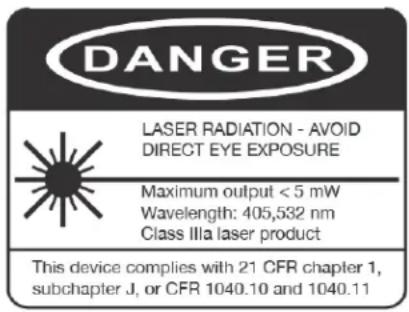

natural_image
Black triangular warning symbol with exclamation mark (no text or numbers)DOCUMENT VERSION
An updated version of this document may be available online.
Please check www.eliminatorlighting.com for the latest revision/update of this document before beginning installation and use.

| Date | Document Version | Software Version | DMX Channels Notes |
| 04/20/2021 | 1.0 1.0 9 Channels Initial Release | ||
CONTENTS
| General Information 4 | |
| Limited Warranty (USA Only) 5 | |
| Safety Guidelines 6 | |
| Laser Warnings and Safety 8 | |
| Maintenance Guidelines 10 | |
| DMX Setup 11 | |
| Overview 14 | |
| Installation Instructions 15 | |
| System Menu 17 | |
| DMX Traits 19 | |
| Dimensional Drawing 23 | |
| Specifications 24 |
GENERAL INFORMATION
INTRODUCTION
Please read and understand all instructions in this manual carefully and thoroughly before attempting to operate this product. These instructions contain important safety and use information.
UNPACKING: This product has been thoroughly tested and has been shipped in perfect condition. Carefully check the shipping carton for damage that may have occurred during shipping. If the carton appears to be damaged, carefully inspect your product for damage and be sure all accessories necessary to assemble the product have arrived intact. In the event that damage has been found or parts are missing, please contact our customer support team for further instructions. Please do not return this product to your dealer without first contacting customer support at the number listed below. Please do not discard the shipping carton in the trash. Please recycle whenever possible.
INCLUDED ITEMS
- Mounting Bracket (x1)
- Bracket Adjustment Knobs (x2)
- Power Cable (x1)
- Laser Safety Key (x1)
CUSTOMER SUPPORT
Tel: (323) 213-4592 | Fax: (323) 582-2941
www.eliminatorlighting.com | support@eliminatorlighting.com
WARRANTY RETURNS
All returned service items, whether under warranty or not, must be freight pre-paid and accompanied by a return authorization (R.A.) number. The R.A. number must be clearly written on the outside of the return package. A brief description of the problem as well as the R.A. number must also be written down on a piece of paper and included in the shipping container. If the unit is under warranty, you must provide a copy of your proof of purchase invoice. Items returned without an R.A. number clearly marked on the outside of the package will be refused and returned at customer's expense. You may obtain an R.A. number by contacting customer support.
Warning! To prevent or reduce the risk of electrical shock or fire, do not expose this unit to rain or moisture.
Warning! This unit is capable of causing severe eye damage. Avoid looking directly into the laser source and/or light source at all times!
Caution! There are no user serviceable parts inside this unit. Do not attempt to perform any repairs yourself, as doing so will void your manufacturer's warranty. In the unlikely event that your unit may require service, please contact Eliminator Lighting. Eliminator Lighting will not accept any liability for any resulting damages caused by the non-observance of information in this manual or any unauthorized modifications to this unit.
During operation, the housing may become extremely hot. Avoid touching the unit with bare hands while in use.
LIMITED WARRANTY (USA ONLY)
A. Eliminator Lighting, an ADJ Products, LLC brand, hereby warrants, to the original purchaser, ADJ Products, LLC products to be free of manufacturing defects in material and workmanship for a prescribed period from the date of purchase (see specific warranty period listed below). This warranty shall be valid only if the product is purchased within the United States of America, including possessions and territories. It is the owner's responsibility to establish the date and place of purchase by acceptable evidence, at the time service is sought.
B. For warranty service you must obtain a Return Authorization number (RA#) before sending back the product, please contact ADJ Products, LLC Service Department at 800-322-6337. Send the product only to the ADJ Products, LLC factory. All shipping charges must be pre-paid. If the requested repairs or service (including parts replacement) are within the terms of this warranty, ADJ Products, LLC will pay return shipping charges only to a designated point within the United States. If the entire instrument is sent, it must be shipped in its original package. No accessories should be shipped with the product. If any accessories are shipped with the product, ADJ Products, LLC shall have no liability whatsoever for loss of or damage to any such accessories, or for the safe return thereof.
C. This warranty is void if the serial number has been altered or removed; if the product is modified in any manner which ADJ Products, LLC concludes, after inspection, affects the reliability of the product; if the product has been repaired or serviced by anyone other than the ADJ Products, LLC factory unless prior written authorization was issued to purchaser by ADJ Products, LLC; if the product is damaged because not properly maintained as set forth in the instruction manual.
D. This is not a service contract, and this warranty does not include maintenance, cleaning or periodic check-up. During the period specified above, ADJ Products, LLC will replace defective parts at its expense with new or refurbished parts, and will absorb all expenses for warranty service and repair labor by reason of defects in material or workmanship. The sole responsibility of ADJ Products, LLC under this warranty shall be limited to the repair of the product, or replacement thereof, including parts, at the sole discretion of ADJ Products, LLC. All products covered by this warranty were manufactured after August 15, 2012, and bear identifying marks to that effect.
E. ADJ Products, LLC reserves the right to make changes in design and/or improvements upon its products without any obligation to include these changes in any products theretofore manufactured. No warranty, whether expressed or implied, is given or made with respect to any accessory supplied with products described above. Except to the extent prohibited by applicable law, all implied warranties made by ADJ Products, LLC in connection with this product, including warranties of merchantability or fitness, are limited in duration to the warranty period set forth above. And no warranties, whether expressed or implied, including warranties of merchantability or fitness, shall apply to this product after said period has expired. The consumer's and/or Dealer's sole remedy shall be such repair or replacement as is expressly provided above; and under no circumstances shall ADJ Products, LLC be liable for any loss or damage, direct or consequential, arising out of the use of, or inability to use, this product.
This warranty is the only written warranty applicable to Eliminator Lighting, an ADJ Products, LLC brand, and supersedes all prior warranties and written descriptions of warranty terms and conditions heretofore published.
MANUFACTURER'S LIMITED WARRANTY PERIODS:
All Eliminator Lighting products (except laser diodes) = 1-year (365 days) Limited Warranty (Such as: Special Effect Lighting, Intelligent Lighting, UV lighting, Strobes, Fog Machines, Bubble Machines, Mirror Balls, Par Cans, Trussing, Lighting Stands etc., excluding lamps)
Laser Products = 1 Year (365 Days) Limited Warranty (excluding laser diodes which have a 6 month limited warranty)
Batteries = 180 Day Limited Warranty
To register your Eliminator Lighting product online, please click here to the ADJ Warranty Registration Page: https://www.adj.com/portal/user/register/
SAFETY GUIDELINES

natural_image
Black triangular warning symbol with exclamation mark (no text or numbers)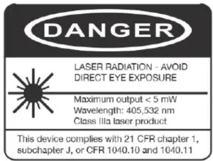

natural_image
Black triangular warning symbol with exclamation mark (no text or numbers)
THERE ARE NO USER SERVICEABLE PARTS INSIDE THESE DEVICES. DO NOT ATTEMPT ANY REPAIRS YOURSELF; DOING SO WILL VOID YOUR MANUFACTURER'S WARRANTY. DAMAGES RESULTING FROM MODIFICATIONS TO THESE DEVICES AND/OR THE DISREGARD OF SAFETY INSTRUCTIONS AND GUIDELINES IN THIS MANUAL VOID THE MANUFACTURER'S WARRANTY AND ARE NOT SUBJECT TO ANY WARRANTY CLAIMS AND/OR REPAIRS.

NEVER TOUCH FIXTURE DURING OPERATION, AS IT MAY BE HOT! ALWAYS REPLACE FUSES WITH REPLACEMENTS OF THE SAME TYPE! KEEP FLAMMABLE MATERIALS AWAY FROM THESE DEVICES!

INDOOR / DRY LOCATIONS USE ONLY! DO NOT EXPOSE DEVICES TO RAIN AND/OR MOISTURE!

NEVER LOOK DIRECTLY INTO THE LIGHT SOURCE OR LASER! RETINA INJURY RISK - MAY INDUCE BLINDNESS! SENSITIVE PERSONS MAY SUFFER AN EPILEPTIC SHOCK!
SAFETY GUIDELINES
This unit may "pop" the fuse if the maximum allotted load of 3 amps is reached.
- To reduce the risk of electrical shock or fire, do not expose this unit rain or moisture.
- Do not spill water or other liquids into or on to your unit.
- Do not attempt to remove or break off the ground prong from the electrical cord. This prong is used to reduce the risk of electrical shock and fire in case of an internal short.
- Do not attempt to operate this unit if the power cord has been frayed or broken.
- Disconnect from main power before making any type of connection.
- Do not remove the cover under any conditions. There are no user serviceable parts inside.
- Always be sure to mount this unit in an area that will allow proper ventilation. Allow about 6" (15cm) between this device and a wall.
- Do not attempt to operate this unit if it has been damaged in any way.
• This unit is intended for indoor use only. Use of this product outdoors voids all warranties. - During long periods of non-use, disconnect the unit's main power.
• Always mount this unit in safe and stable matter. - Power cords should be routed so they are not likely to be walked on, pinched by items placed upon or against them.
- Cleaning - The fixture should be cleaned only as recommended by the manufacturer. See the Maintenance Guidelines section of this manual for cleaning details.
- Heat - The appliance should be situated away from heat sources such as radiators, heat registers, stoves, or other appliances (including amplifiers) that produce heat.
- The fixture should be serviced by qualified service personnel when:
A. The power-supply cord or the plug has been damaged.
B. Objects have fallen, or liquid has been spilled into, the unit.
C. The unit has been exposed to rain or water.
D. The unit does not appear to operate normally or exhibits a marked change in performance.
LASER WARNINGS AND SAFETY
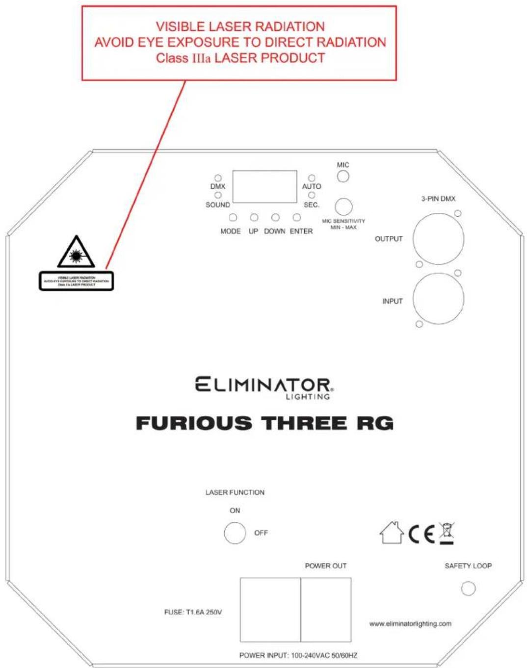
After completing setup, and before public use, test the laser to ensure proper function. Do not use if any defects are detected. Do not use if the laser emits only a few laser beams rather than dozens/hundreds, as this could indicate damage to the diffraction grating optic, and could allow emission of laser intensity levels that exceed Class 3R.
- Do not point lasers at people or animals. Never look into the laser aperture or directly at laser beams.
- Do not point lasers into areas which could create instances of unintentional or harmful exposure, such as uncontrolled balconies, etc.
- Do not point lasers at highly reflective surfaces, such as windows, mirrors, and shiny metal. Even laser reflections can be hazardous.
- Never point a laser at aircraft. This is a federal offense.
- Never point un-terminated laser beams into the sky.
- Do not expose the output optic (aperture) to cleaning chemicals.
- Do not use laser if the laser appears to be emitting only a few beams.
- Do not use the laser if the housing is damaged, the housing is open, or if the optics appear damaged in any way.
- Never open the laser housing. The high laser power levels inside of the protective housing can start fires, burn skin, and will cause instantaneous eye injury.
- Never leave this device running unattended.
- The operation of a class 3R laser show is only allowed if the show is controlled by a skilled and well-trained operator who is familiar with the information enclosed in this manual.
- The legal requirements for using laser entertainment products vary from country to country. The user is responsible for determining the legal requirements at the location/country of use.
• Always use proper lighting safety cables when hanging lights and effects overhead.
LASER WARNINGS AND SAFETY
MAINTENANCE GUIDELINES

DISCONNECT POWER BEFORE PERFORMING ANY CLEANING OR MAINTENANCE!
CLEANING
Frequent cleaning is recommended to ensure proper function, optimized light output, and an extended life. The frequency of cleaning depends on the environment in which the device operates: damp, smoky, or particularly dirty environments can cause greater accumulation of dirt on the fixture housing and/or light fixture optics. Clean the external surface and the front lens of the device periodically with a soft cloth to avoid dirt/debris accumulation
NEVER use alcohol, solvents, or ammonia-based cleaners.
MAINTENANCE
Regular inspections are recommended to ensure proper function and extended life. There are no user serviceable parts inside these devices; please refer all other service issues to Eliminator Lighting. Should you need any spare parts, please order genuine parts from Eliminator Lighting.
Please refer to the following points during routine inspections:
- A detailed review should be performed by an approved electrical engineer every three months, to make sure the circuit contacts are in good condition in order to prevent overheating.
- Be sure all screws and fasteners are securely tightened at all times. Loose screws may fall out during normal operation, resulting in damage or injury as larger parts could fall.
- Check for any deformations on the unit. Deformations could allow for dust to enter into the device, or cause the device to fall and seriously injure a person(s).
• Electric power supply cables must not show any damage, material fatigue, or sediments.
FUSE REPLACEMENT
This device features a replaceable fuse located alongside the Power Input on the back side of the device. To access the fuse, use a flat head screwdriver to catch the groove in the wall of the Power Input. BE CAREFUL NOT TO DAMAGE THE FUSE CLIP, THE POWER INPUT, OR THE PRONGS. When replacing the fuse, be sure to replace the correct one, as the fuse clip contains both an operational fuse and a spare fuse. Replace the fuse only with an identical F2A 250V fuse.
DMX SETUP
DMX-512: DMX is short for Digital Multiplex. This is a universal protocol used as a form of communication between intelligent fixtures and controllers. A DMX controller sends DMX data instructions from the controller to the fixture. DMX data is sent as serial data that travels from fixture to fixture via the DATA "IN" and DATA "OUT" XLR terminals located on all DMX fixtures (most controllers only have a DATA "OUT" terminal).
DMX Linking: DMX is a language allowing all makes and models of different manufacturers to be linked together and operate from a single controller, as long as all fixtures and the controller are DMX compliant. To ensure proper DMX data transmission, when using several DMX fixtures try to use the shortest cable path possible. The order in which fixtures are connected in a DMX line does not influence the DMX addressing. For example, a fixture assigned a DMX address of 1 may be placed anywhere in a DMX line: at the beginning, at the end, or anywhere in the middle. When a fixture is assigned a DMX address of 1, the DMX controller knows to send DATA assigned to address 1 to that unit, no matter where it is located in the DMX chain.
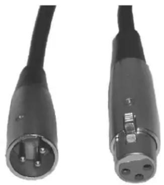
Data Cable (DMX Cable) Requirements (For DMX Operation): This device can be controlled via DMX-512 protocol. The DMX address is set using the display screen on the back of the device. Your unit and your DMX controller require a standard 3-pin XLR connector for data input and data output (Figure 1). We recommend Accu-Cable DMX cables. If you are making your own cables, be sure to use standard 110-120 Ohm shielded cable (This cable may be purchased at almost all pro lighting stores). Your cables should be made with a male XLR connector on one end and a female XLR connector on the other. Also remember that DMX cable must be daisy chained and cannot be split.
natural_image
Close-up of two black electronic connectors with metallic pins, shown from side and top views (no text or symbols visible)Figure 1
DMX SETUP
Notice: Be sure to follow figures two and three when making your own cables. Do not use the ground lug on the XLR connector. Do not connect the cable's shield conductor to the ground lug or allow the shield conductor to come into contact with the XLR cable's outer casing. Grounding the shield could cause a short circuit and erratic behavior.
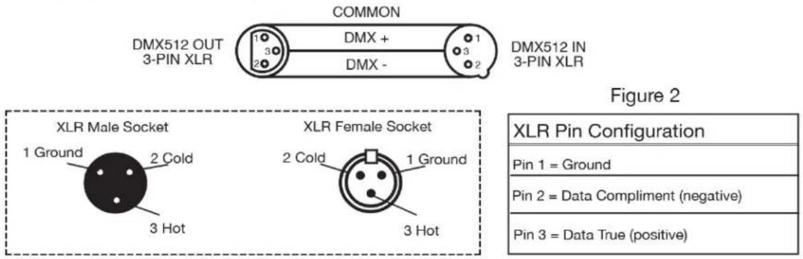
Figure 3
Special Note: Line Termination. When longer runs of cable are used, you may need to use a terminator on the last unit to avoid erratic behavior. A terminator is a 110-120 ohm 1/4 watt resistor which is connected between pins 2 and 3 of a male XLR connector (DATA+ and DATA-). This unit is inserted in the female XLR connector of the last unit in your daisy chain to terminate the line. Using a cable terminator will decrease the chances of erratic behavior.
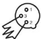
Termination reduces signal errors and avoids signal transmission problems and interference. It is always advisable to connect a DMX terminal, (Resistance 120 Ohm 1/4 W) between PIN 2 (DMX-) and PIN 3 (DMX +) of the last fixture.
Figure 4
5-Pin XLR DMX Connectors. Some manufacturers use 5-pin DMX-512 data cables for DATA transmission instead of 3-pin connectors. 5-pin DMX fixtures may be implemented in a 3-pin DMX line. When inserting standard 5-pin data cables in to a 3-pin line, a cable adaptor must be used. These adaptors are readily available at most electronics stores. The chart below details a proper cable conversion.
| 3-Pin XLR to 5-Pin XLR Conversion | ||
| Conductor | 3-Pin XLR Female (Out) | 5-Pin XLR Male (In) |
| Ground/Shield | Pin 1 | Pin 1 |
| Data Compliment (- signal) | Pin 2 | Pin 2 |
| Data True (+ signal) | Pin 3 | Pin 3 |
| Not Used | Do Not Use | |
| Not Used | Do Not Use | |
DMX SETUP
DMX ADDRESSING
All fixtures should be given a DMX starting address when operating with a DMX controller, in order to ensure that the correct fixture responds to the correct control signal. This digital starting address is the channel number from which the fixture starts to “listen” to the digital control signal sent out from the DMX controller. This starting DMX address is assigned by setting the correct DMX address on the digital control display on the fixture.
You can set the same starting address for all fixtures or a group of fixtures, or set different addresses for each individual fixture. Setting all fixtures to the same DMX address will cause all fixtures to react in the same way. In this case, please note that changing the settings of one channel will affect all the fixtures simultaneously.
If you set each fixture to a different DMX address, each unit will start to "listen" to the channel number you have set, based on the quantity of DMX channels of each fixture. That means changing the settings of one channel will only affect the selected fixture.
As an example, since this device has 9 DMX channels, you should set the starting DMX address of the first unit to 1, the second unit to 10 (1 + 9), the third unit to 19 (1 + 9 + 9), and so on. (See the chart below for more details.)
| Channel Mode Unit 1 Address Unit 2 | Address Unit 3 Address Unit 4 Address | ||
| 9-Ch | 1 10 19 28 | ||
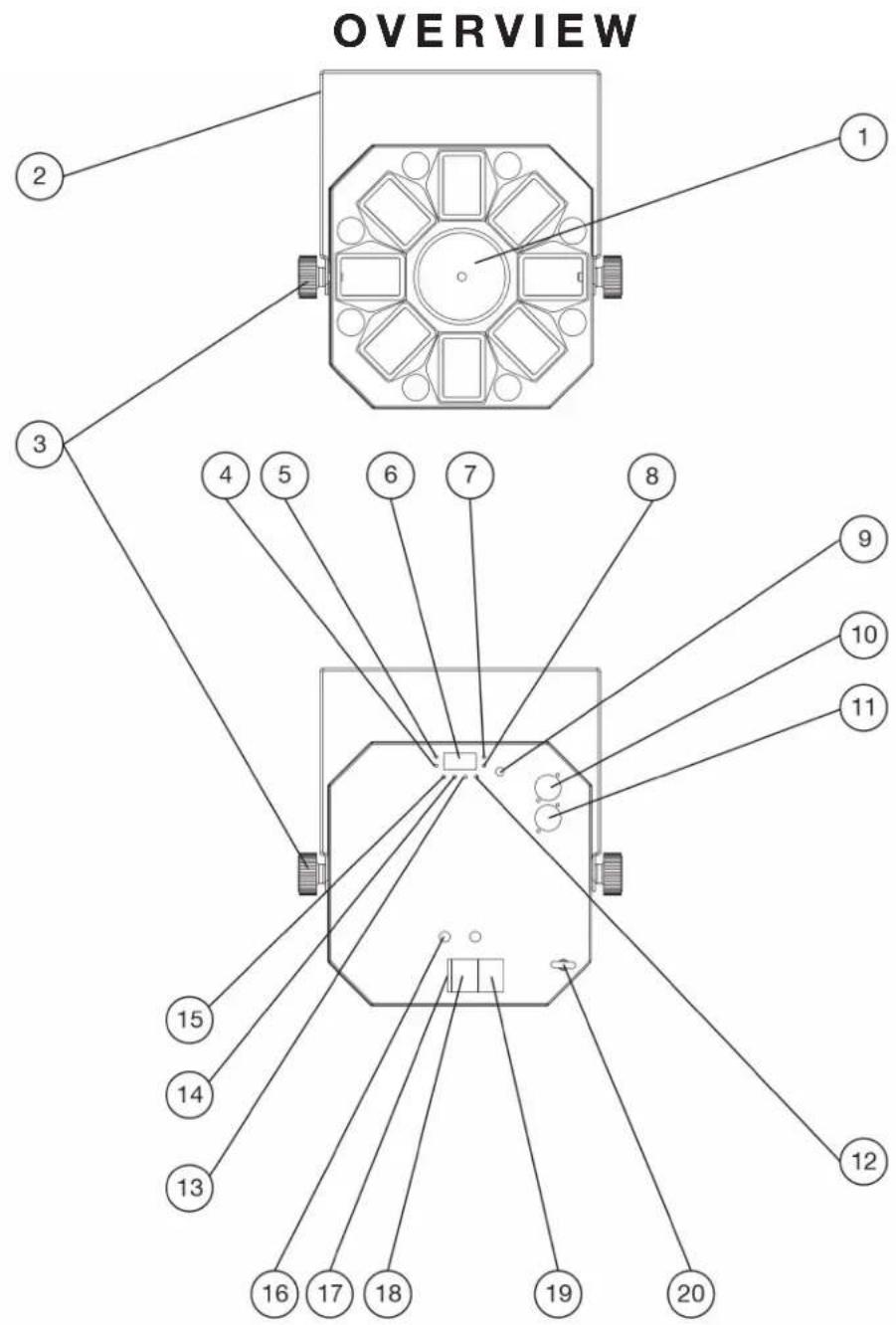
- Laser Aperture
- Mounting Bracket
- Bracket Adjustment Knobs (x2)
- Sound Indicator
- DMX Indicator
- Display Screen
- Auto Mode Indicator
- Secondary Mode Indicator
- Sound Sensitivity Adjustment
-
DMX Out
-
DMX In
- Enter Button
- Down Button
- Up Button
- Function Button
- Laser Safety Switch
- Fuse
- Power In
- Power Out
- Safety Cable Loop
INSTALLATION INSTRUCTIONS

FLAMMABLE MATERIAL WARNING
Keep devices at least 5.0 feet (1.5m) away from flammable materials and/or pyrotechnics.

ELECTRICAL CONNECTIONS
A qualified electrician should be used for all electrical connections and/or installations.

DO NOT INSTALL THE DEVICE IF YOU ARE NOT QUALIFIED TO DO SO!
OVERHEAD RIGGING REQUIRES EXTENSIVE EXPERIENCE, INCLUDING CALCULATING WORKING LOAD LIMITS, KNOWLEDGE OF INSTALLATION MATERIAL BEING USED, AND PERIODIC SAFETY INSPECTION OF ALL INSTALLATION MATERIALS. IF YOU LACK THESE QUALIFICATIONS, DO NOT ATTEMPT THE INSTALLATION YOURSELF. IMPROPER INSTALLATION CAN RESULT IN BODILY INJURY.
BEFORE RIGGING/MOUNTING DEVICES TO ANY METAL TRUSS/STRUCTURE OR CEILING, A PROFESSIONAL EQUIPMENT INSTALLER MUST BE CONSULTED TO DETERMINE WHETHER THE METAL TRUSS/STRUCTURE OR CEILING IS PROPERLY CERTIFIED TO SAFELY HOLD THE COMBINED WEIGHT OF THE LIGHT FIXTURE, CLAMPS, CABLES, AND ACCESSORIES. BEFORE MOUNTING DEVICES TO ANY SURFACE OR STRUCTURE, MAKE SURE THE SURFACE OR STRUCTURE CAN HOLD A MINIMUM POINT LOAD OF 10 TIMES THE WEIGHT OF THE DEVICES.
MAKE SURE SCREWS AND/OR ANCHOR BOLTS (NOT INCLUDED) FIT INTO MOUNTING HOLES!
FOR ADDED PROTECTION, MOUNT DEVICES OUTSIDE WALKING PATHS, SEATING AREAS, OR AREAS WHERE UNAUTHORIZED PERSONNEL CAN REACH THE DEVICES.
SECURE FIXTURE WITH A SECONDARY SAFETY ATTACHMENT, SUCH AS AN APPROPRIATE SAFETY CABLE. (NOT INCLUDED)
NEVER STAND DIRECTLY BELOW THE DEVICES WHEN MOUNTING, REMOVING OR SERVICING.
DEVICES MUST ALL BE INSTALLED FOLLOWING ALL LOCAL, NATIONAL, AND COUNTRY COMMERCIAL ELECTRICAL AND CONSTRUCTION CODES AND REGULATIONS.
INSTALLATION INSTRUCTIONS
CLAMP INSTALLATION
This fixture features a mounting clamp attachment point, which is located on the mounting yoke, as well as a safety cable rigging point, located on the rear face of the unit near the power connection (see the illustration below). When mounting the fixture to a truss or any other suspended or overhead installation, be sure to secure an appropriately rated clamp (not included) to the clamp attachment point and attach a separate SAFETY CABLE of the appropriate safety rating to the safety cable rigging point.
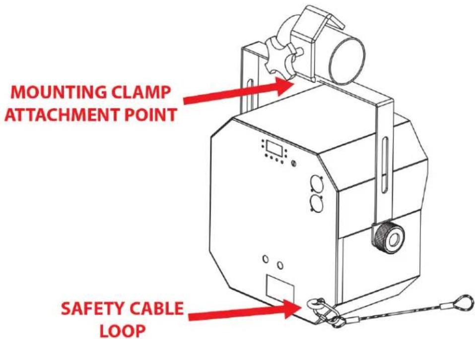

SAFETY CABLE: ALWAYS ATTACH A SAFETY CABLE WHENEVER INSTALLING THIS FIXTURE IN A SUSPENDED ENVIRONMENT TO ENSURE THAT THE FIXTURE WILL NOT FALL IF THE CLAMP FAILS.
RIGGING
Overhead rigging requires extensive experience, including but not limited to: calculating working load limits, understanding the installation material being used, and periodic safety inspection of all installation material and the fixture itself. If you lack these qualifications, do not attempt to perform the installation yourself. Improper installation can result in bodily injury.
SYSTEM MENU
CONTROL PANEL
The device includes an easy to navigate system menu that can be accessed via a set of control buttons located on the back face of the device below the digital display.
FUNC: Press to cycle through main menu options (Auto, Sound, Secd, DMX).
ENTER: Press to confirm selection and open up the option sub-menu, if applicable.
UP/DOWN: Press to scroll through menu or sub-menu options.
natural_image
Empty white rectangle with black border (no text or symbols)
SYSTEM MENU
| Auto | Aut0: Laser + RGBWY + 8x1WLED | ENTER to confirm, then UP/DOWN to select display speed.S0 (fastest) to S100 (slowest). |
| Aut1: Laser + RGBWY | ||
| Aut2: Laser + 8x1WLED | ||
| Aut3: RGBWY + 8x1WLED | ||
| Aut4: RGBWY | ||
| Aut5: Laser | ||
| Aut6: 8x1WLED | ||
| Sound | Sou0: Laser + RGBWY + 8x1WLED | ENTER to confirm, then adjust sensitivity with Sound Sensitivity Adjustment knob. |
| Sou1: Laser + RGBWY | ||
| Sou2: Laser + 8x1WLED | ||
| Sou3: RGBWY + 8x1WLED | ||
| Sou4: RGBWY | ||
| Sou5: Laser | ||
| Sou6: 8x1WLED | ||
| Secd | When selected, the unit will follow the movements of a designated primary unit. | NOTE: A flashing display screen indicates a poor connection to the primary unit. Please check the cable connections. |
| DMX | D001 - D506 | NOTE: A flashing display screen indicates a poor DMX connection. Please check the cable connections. |
DMX TRAITS
| Eliminator Furious Three RG - DMX Traits | ||
| Software Version 1.0 | ||
| CHANNEL DMX VALUE DESCRIPTION | ||
| 1 | Mode | |
| 0 - 9 No Function | ||
| 10 - 24 Aut0 | ||
| 25 - 39 Aut1 | ||
| 40 - 54 Aut2 | ||
| 55 - 69 Aut3 | ||
| 70 - 84 Aut4 | ||
| 85 - 99 Aut5 | ||
| 100 - 114 Aut6 | ||
| 115 - 129 Sou0 | ||
| 130 - 144 Sou1 | ||
| 145 - 159 Sou2 | ||
| 160 - 174 Sou3 | ||
| 175 - 189 Sou4 | ||
| 190 - 204 Sou5 | ||
| 205 - 220 Sou6 | ||
| 221 - 255 DMX Mode | ||
| 2 | LED Operation | |
| 0 - 9 No Function | ||
| 10 - 14 Red | ||
| 15 - 19 Green | ||
| 20 - 24 Blue | ||
| 25 - 29 Yellow | ||
| 30 - 34 White | ||
| 35 - 39 Red + White | ||
| 40 - 44 Red + Green | ||
| 45 - 49 Green + Blue | ||
| 50 - 54 Blue + Yellow | ||
| 55 - 59 Yellow + White | ||
| 60 - 64 Green + White | ||
| 65 - 69 Green + Yellow | ||
| CONTINUED ON NEXT PAGE | ||
DMX TRAITS
| Eliminator Furious Three RG - DMX Traits | ||
| Software Version 1.0 | ||
| CHANNEL DMX VALUE DESCRIPTION | ||
| 2 | LED Operation (continued) | |
| 70 - 74 Red | + Yellow | |
| 75 - 79 Red | + Blue | |
| 80 - 84 Blue | + White | |
| 85 - 89 Red | + Green + Blue | |
| 90 - 94 Red | + Green + Yellow | |
| 95 - 99 Red | + Green + White | |
| 100 - 104 Red | + Blue + Yellow | |
| 105 - 109 Red | + Blue + White | |
| 110 - 114 Red | + Yellow + White | |
| 115 - 119 Green | + Blue + Yellow | |
| 120 - 124 Green | + Blue + White | |
| 125 - 129 Green | + Yellow + White | |
| 130 - 134 Blue | + Yellow + White | |
| 135 - 139 Red | + Green + Blue + Yellow | |
| 140 - 144 Red | + Green + Blue + White | |
| 145 - 149 Green | + Blue + White + Yellow | |
| 150 - 154 Red | + Green + White + Yellow | |
| 155 - 159 Red | + Blue + White + Yellow | |
| 160 - 164 Red | + Green + Blue + Yellow + White | |
| 165 - 209 Automatic (single colors only) | ||
| 210 - 255 Automatic (two colors at a time) | ||
| 30 - 255 | Automatic Speed, slow to fast (when CH2 is set to a DMX value between 165 - 209) | |
| 4 | LED Strobe | |
| 0 - 4 No Function | ||
| 5 - 254 Strobe Speed, slow to fast | ||
| 255 Sound-Activated Strobe Mode | ||
| CONTINUED ON NEXT PAGE | ||
DMX TRAITS
| Eliminator Furious Three RG - DMX Traits | ||
| Software Version 1.0 | ||
| CHANNEL DMX VALUE DESCRIPTION | ||
| 5 | 8-piece LED Control | |
| 0 - 9 No Function | ||
| 10 - 19 Picture 1, slow to fast | ||
| 20 - 29 Picture 2, slow to fast | ||
| 30 - 39 Picture 3, slow to fast | ||
| 40 - 49 Picture 4, slow to fast | ||
| 50 - 59 Picture 5, slow to fast | ||
| 60 - 69 Picture 6, slow to fast | ||
| 70 - 79 Picture 7, slow to fast | ||
| 80 - 89 Picture 8, slow to fast | ||
| 90 - 99 Picture 9, slow to fast | ||
| 100 - 109 Picture 10, slow to fast | ||
| 110 - 255 On | ||
| 6 | Laser | |
| 0 - 9 No Function | ||
| 10 - 49 Red On | ||
| 50 - 89 Green On | ||
| 90 - 129 | Red and Green Alternating Strobe (CH7 must be set to appropriate value) | |
| 130 - 169 Red On, Green Strobe (CH7 must be set to appropriate value) | ||
| 170 - 209 Green On, Red Strobe (CH7 must be set to appropriate value) | ||
| 210 - 255 Red and Green Strobe (CH7 must be set to appropriate value) | ||
| 7 | Laser Strobe | |
| 0 - 4 No Function | ||
| 5 - 254 Strobe, fast to slow | ||
| 255 Sound-Activated Strobe Mode | ||
| 8 | LED Rotate | |
| 0 - 4 Stop | ||
| 5 - 127 Clockwise, slow to fast | ||
| 128 - 133 Stop | ||
| 134 - 255 Counter-clockwise, slow to fast | ||
| CONTINUED ON NEXT PAGE | ||
DMX TRAITS
| Eliminator Furious Three RG - DMX Traits | ||
| Software Version 1.0 | ||
| CHANNEL DMX VALUE DESCRIPTION | ||
| 9 | Laser Rotate | |
| 0 - 4 Stop | ||
| 5 - 127 Rotate Clockwise, slow to fast | ||
| 128 - 133 Stop | ||
| 134 - 255 Rotate Counter-Clockwise, slow to fast | ||
DIMENSIONAL DRAWING
SPECIFICATIONS
• 3-FX-IN-1 dance party lighting effect: LED Moonflower, Wash and laser effects
- Dozens of razor-sharp beams fill a dance floor, ceiling or wall
- Moonflower: 5 x 3W (RGBWY) 5-in-1 LEDs
- Wash: 6 x 3W (RGBY) Quad LEDs
- Laser: Red & Green laser diodes
• 4 control mode: DMX, Sound Active, Auto, Primary/Secondary
• 4-button LED display menu
- 9 DMX channels
• Electronic dimming: 0-100%
• 3-pin DMX In/Out
• IEC AC In/Out connectors to daisy chain power
- Laser On/Off with safety key
- Safety eye on rear panel
• Built-in microphone with sensitivity potentiometer
- With wired digital communication network
• Power Draw: 40W max
- Dimensions: 11.8" x 12.25"x 8.9" / 300x312x226mm
• Weight: 8 lbs. / 3.7 kg.
- Furious Three RG Furious Three RG
- User Manual
- Eliminator Lighting USA
- DOCUMENT VERSION
- CONTENTS
- GENERAL INFORMATION
- INTRODUCTION
- INCLUDED ITEMS
- CUSTOMER SUPPORT
- WARRANTY RETURNS
- LIMITED WARRANTY (USA ONLY)
- MANUFACTURER'S LIMITED WARRANTY PERIODS:
- SAFETY GUIDELINES
- LASER WARNINGS AND SAFETY
- MAINTENANCE GUIDELINES
- DISCONNECT POWER BEFORE PERFORMING ANY CLEANING OR MAINTENANCE!
- CLEANING
- MAINTENANCE
- FUSE REPLACEMENT
- DMX SETUP
- DMX ADDRESSING
- INSTALLATION INSTRUCTIONS
- FLAMMABLE MATERIAL WARNING
- ELECTRICAL CONNECTIONS
- DO NOT INSTALL THE DEVICE IF YOU ARE NOT QUALIFIED TO DO SO!
- CLAMP INSTALLATION
- RIGGING
- SYSTEM MENU
- CONTROL PANEL
- DIMENSIONAL DRAWING
- SPECIFICATIONS
Brand : Eliminator Lighting
Model : Furious Three RG
Category : Uncategorized