
ASMB7-IKVM - Electronic board ASUS - Free user manual and instructions
Find the device manual for free ASMB7-IKVM ASUS in PDF.


| Product Type | Server Management Board |
| Model | ASMB7-iKVM |
| Brand | ASUS |
| Chipset | Aspeed 2300 |
| Internal RAM | 224 MB (system) + 32 MB (video) |
| Internal ROM | 32 MB |
| Form Factor | 22 mm x 17 mm |
| IPMI Compliance | IPMI 2.0 (RMCP+, KCS, LAN) |
| KVM over LAN | Yes (web-based remote console) |
| Virtual Media | Yes (2 remote storage: USB/CD-ROM/DVD and image) |
| Network Bonding | Supported |
| Watchdog Timer | 32-bit |
| Supported Host Interfaces | KCS, SMIC, BT, PCI, KCS2 |
| Web Management | HTTPS (SSL), Java Console |
| Security Features | SSL encryption, RADIUS, LDAP, Active Directory authentication |
| Notification | PET, SNMP Trap, Email alerts |
| Package Contents | ASMB7-iKVM card, Support CD, User Guide |
| Maintenance | Keep away from dust and moisture; handle with care to avoid static discharge |
Frequently Asked Questions - ASMB7-IKVM ASUS
User questions about ASMB7-IKVM ASUS
0 question about this device. Answer the ones you know or ask your own.
Ask a new question about this device
Download the instructions for your Electronic board in PDF format for free! Find your manual ASMB7-IKVM - ASUS and take your electronic device back in hand. On this page are published all the documents necessary for the use of your device. ASMB7-IKVM by ASUS.
USER MANUAL ASMB7-IKVM ASUS
Server Management Board
E8098
First Edition V1
March 2013
Copyright © 2013 ASUSTeK COMPUTER INC. All Rights Reserved.
No part of this manual, including the products and software described in it, may be reproduced, transmitted, transcribed, stored in a retrieval system, or translated into any language in any form or by any means, except documentation kept by the purchaser for backup purposes, without the express written permission of ASUSTeK COMPUTER INC. ("ASUS").
Product warranty or service will not be extended if: (1) the product is repaired, modified or altered, unless such repair, modification of alteration is authorized in writing by ASUS; or (2) the serial number of the product is defaced or missing.
ASUS PROVIDES THIS MANUAL "AS IS" WITHOUT WARRANTY OF ANY KIND, EITHER EXPRESS OR IMPLIED, INCLUDING BUT NOT LIMITED TO THE IMPLIED WARRANTIES OR CONDITIONS OF MERCHANTABILITY OR FITNESS FOR A PARTICULAR PURPOSE. IN NO EVENT SHALL ASUS, ITS DIRECTORS, OFFICERS, EMPLOYEES OR AGENTS BE LIABLE FOR ANY INDIRECT, SPECIAL, INCIDENTAL, OR CONSEQUENTIAL DAMAGES (INCLUDING DAMAGES FOR LOSS OF PROFITS, LOSS OF BUSINESS, LOSS OF USE OR DATA, INTERRUPTION OF BUSINESS AND THE LIKE), EVEN IF ASUS HAS BEEN ADVISED OF THE POSSIBILITY OF SUCH DAMAGES ARISING FROM ANY DEFECT OR ERROR IN THIS MANUAL OR PRODUCT.
SPECIFICATIONS AND INFORMATION CONTAINED IN THIS MANUAL ARE FURNISHED FOR INFORMATIONAL USE ONLY, AND ARE SUBJECT TO CHANGE AT ANY TIME WITHOUT NOTICE, AND SHOULD NOT BE CONSTRUED AS A COMMITMENT BY ASUS. ASUS ASSUMES NO RESPONSIBILITY OR LIABILITY FOR ANY ERRORS OR INACCURACIES THAT MAY APPEAR IN THIS MANUAL, INCLUDING THE PRODUCTS AND SOFTWARE DESCRIBED IN IT.
Products and corporate names appearing in this manual may or may not be registered trademarks or copyrights of their respective companies, and are used only for identification or explanation and to the owners' benefit, without intent to infringe.
Contents
Notices ...... vi
Safety information ...... viii
About this guide ix
ASMB7-iKVM specifications summary.... xi
Chapter 1: Product introduction
1.1 Welcome! 1-2
1.2 Package contents 1-2
1.3 Features 1-3
1.4 System requirements 1-4
1.5 Network setup 1-5
Chapter 2: Installation
2.1 Before you proceed 2-2
2.2 Hardware installation 2-2
2.3 Firmware update and IP configuration 2-4
2.3.1 Firmware update 2-4
2.3.2 Configure BMC IP source static IP 2-6
2.3.3 Configure BMC IP source DHCP 2-7
2.4 BIOS configuration 2-8
2.4.1 Running the BIOS BMC configuration 2-8
2.4.2 BMC network configuration 2-8
2.4.3 System Event Log 2-10
2.4.4 IPv6 BMC Network Configuration 2-11
2.5 Running the ASMC7 utility 2-13
2.5.1 Configuring the LAN controller 2-15
2.5.2 Configuring the user name and password 2-16
Chapter 3: ASUS Host Management Controller Set-up
3.1 ASUS Host Management Controller Setup 3-2
3.1.1 Installing and launching the ASUS Host Management Controller Setup utility ....3-2
3.1.2 Command fields 3-3
3.1.3 Initial 3-3
3.1.4 View 3-3
3.1.5 Set 3-6
Contents
3.1.6 Monitor 3-8
3.1.7 Help 3-9
Chapter 4: Web-based user interface
4.1 Web-based user interface 4-2
4.1.1 Logging in the utility 4-2
4.1.2 Using the utility 4-3
4.2 FRU Information 4-4
4.3 Server Health 4-4
4.3.1 Sensor Readings (with Thresholds) 4-5
4.3.2 Event Log 4-5
4.4 Configuration....4-6
4.4.1 Active Directory 4-6
4.4.2 DNS 4-9
4.4.3 LDAP 4-9
4.4.4 Mouse Mode 4-12
4.4.5 Network 4-12
4.4.6 Network Bond 4-13
4.4.7 NTP 4-13
4.4.8 PEF 4-14
4.4.9 RADIUS 4-21
4.4.10 Remote Session 4-21
4.4.11 Services 4-22
4.4.12 SMTP 4-22
4.4.13 SSL 4-23
4.4.14 Users 4-28
4.5 Remote Control 4-30
4.5.1 Console Redirection 4-30
4.5.2 Server Power Control 4-38
4.5.3 Chassis Identify Command 4-38
4.5.4 Power Button 4-39
4.6 Maintenance 4-40
4.6.1 Firmware Update 4-40
4.6.2 Restore Factory Default 4-40
Contents
Appendix: Reference information
A.1 BMC connector ....A-2
A.2 LAN ports for server management ...... A-3
A.3 Troubleshooting A-4
A.4 Sensor Table A-5
ASUS contact information .... 1
Notices
Federal Communications Commission Statement
This device complies with Part 15 of the FCC Rules. Operation is subject to the following two conditions:
• This device may not cause harmful interference, and
- This device must accept any interference received including interference that may cause undesired operation.
This equipment has been tested and found to comply with the limits for a Class B digital device, pursuant to Part 15 of the FCC Rules. These limits are designed to provide reasonable protection against harmful interference in a residential installation. This equipment generates, uses and can radiate radio frequency energy and, if not installed and used in accordance with manufacturer's instructions, may cause harmful interference to radio communications. However, there is no guarantee that interference will not occur in a particular installation. If this equipment does cause harmful interference to radio or television reception, which can be determined by turning the equipment off and on, the user is encouraged to try to correct the interference by one or more of the following measures:
• Reorient or relocate the receiving antenna.
- Increase the separation between the equipment and receiver.
- Connect the equipment to an outlet on a circuit different from that to which the receiver is connected.
- Consult the dealer or an experienced radio/TV technician for help.

The use of shielded cables for connection of the monitor to the graphics card is required to assure compliance with FCC regulations. Changes or modifications to this unit not expressly approved by the party responsible for compliance could void the user's authority to operate this equipment.
Canadian Department of Communications Statement
This digital apparatus does not exceed the Class B limits for radio noise emissions from digital apparatus set out in the Radio Interference Regulations of the Canadian Department of Communications.
This class B digital apparatus complies with Canadian ICES-003.
REACH
Complying with the REACH (Registration, Evaluation, Authorization, and Restriction of Chemicals) regulatory framework, we published the chemical substances in our products at ASUS website at http://csr.asus.com/english/REACH.htm.
ASUS Recycling/Takeback Services
ASUS recycling and takeback programs come from our commitment to the highest standards for protecting our environment. We believe in providing solutions for you to be able to responsibly recycle our products, batteries, other components as well as the packaging materials. Please go to http://csr.asus.com/english/Takeback.htm for detailed recycling information in different regions.

DO NOT throw the motherboard in municipal waste. This product has been designed to enable proper reuse of parts and recycling. This symbol of the crossed out wheeled bin indicates that the product (electrical and electronic equipment) should not be placed in municipal waste. Check local regulations for disposal of electronic products.

DO NOT throw the mercury-containing button cell battery in municipal waste. This symbol of the crossed out wheeled bin indicates that the battery should not be placed in municipal waste.
Safety information
Electrical safety
- To prevent electrical shock hazard, disconnect the power cable from the electrical outlet before relocating the server.
- When adding or removing devices to or from the server, ensure that the power cables for the devices are unplugged before the signal cables are connected. If possible, disconnect all power cables from the existing server before you add a device.
- Before connecting or removing signal cables from the server, ensure that all power cables are unplugged.
- Seek professional assistance before using an adapter or extension cord. These devices could interrupt the grounding circuit.
- Make sure that your power supply is set to the correct voltage in your area. If you are not sure about the voltage of the electrical outlet you are using, contact your local power company.
- If the power supply is broken, do not try to fix it by yourself. Contact a qualified service technician or your retailer.
Operation safety
- Before installing any component to the server, carefully read all the manuals that came with the package.
- Before using the product, make sure all cables are correctly connected and the power cables are not damaged. If you detect any damage, contact your dealer immediately.
- To avoid short circuits, keep paper clips, screws, and staples away from connectors, slots, sockets and circuitry.
- Avoid dust, humidity, and temperature extremes. Do not place the product in any area where it may become wet.
- Place the product on a stable surface.
- If you encounter technical problems with the product, contact a qualified service technician or your retailer.
About this guide
This user guide contains the information you need when installing and configuring the server management board.
How this guide is organized
This guide contains the following parts:
• Chapter 1: Product introduction
This chapter describes the server management board features and the new technologies it supports.
• Chapter 2: Installation
This chapter provides instructions on how to install the board to the server system and install the utilities that the board supports.
• Chapter 3: ASUS Host Management Controller Set-up
This chapter tells you how to use the ASUS Host Controller Set-up that the server management board supports.
• Chapter 4: Web-based user interface (ASMB7-iKVM only)
This chapter tells you how to use the web-based user interface that the server management board supports.
- Appendix: Reference Information
The Appendix shows the location of the LAN ports for server management and BMC connector on server motherboards. This section also presents common problems that you may encounter when installing or using the server management board.
Where to find more information
Refer to the following sources for additional information and for product and software updates.
1. ASUS websites
The ASUS website provides updated information on ASUS hardware and software products. Refer to the ASUS contact information.
2. Optional documentation
Your product package may include optional documentation, such as warranty flyers, that may have been added by your dealer. These documents are not part of the standard package.
Conventions used in this guide
To make sure that you perform certain tasks properly, take note of the following symbols used throughout this manual.

DANGER/WARNING: Information to prevent injury to yourself when trying to complete a task.

CAUTION: Information to prevent damage to the components when trying to complete a task.

IMPORTANT: Instructions that you MUST follow to complete a task.

NOTE: Tips and additional information to help you complete a task.
Typography
Bold text Indicates a menu or an item to select.
Italics Used to emphasize a word or a phrase.
Example:
Example:
Command Means that you must type the command exactly as shown, then supply the required item or value enclosed in brackets.
Example: At the DOS prompt, type the command line:
format a:
ASMB7-iKVM specifications summary
| Chipset Aspeed 2300 | |
| Internal RAM | 224 MB for system32 MB for video |
| Internal ROM 32 MB | |
| Timers 32-bit Watchdog Timer | |
| Main features IPMI 2.0-compliant and supportsKVM over LANWeb-based user interface (remote management)Virtual mediaNetwork Bonding support | |
| Form factor 22 mm x 17 mm |
* Specifications are subject to change without notice.
This chapter describes the server management board features and the new technologies it supports.
Product introduction
1.1 Welcome!
Thank you for buying an ASUS® ASMB7-iKVM server management board!
The ASUS ASMB7-iKVM is an Intelligent Platform Management Interface (IPMI) 2.0-compliant board that allows you to monitor, control, and manage a remote server from the local or central server in your local area network (LAN). With ASMB7-iKVM plugging in a server motherboard, you can completely and efficiently monitor your server in real-time. The solution allows you to reduce IT management costs and increase the productivity.
Before you start installing the server management board, check the items in your package with the list below.
1.2 Package contents
Check your server management board package for the following items.
• ASUS ASMB7-iKVM Card
- Support CD
- User guide

If any of the above items is damaged or missing, contact your retailer.
1.3 Features
1. IPMI 2.0
- System interface (KCS)
• LAN interface (support RMCP+) - System Event Log (SEL)
- Sensor Data Record (SDR)
• Field Replaceable Unit (FRU) - Remote Power on/off, reboot
- Serial Over LAN (SOL)
• Authentication Type: RAKP-HMAC-SHA1 - Encryption (AES)
- Platform Event Filtering (PEF)
- Platform Event Trap (PET)
- Watchdog Timer
2. Private I2C Bus
- Auto Monitoring sensors (temperature, voltage, fan speed and logging events)
3. PMBus\*
• Support Power supply for PMBus device
4. PSMI\*
• Support Power supply for PSMI bus device
5. Web-base GUI
• Monitor Sensor, show SDR, SEL, FRU, configure BMC, LAN
• Support SSL (HTTPS)
- Multiple user permission level
- Upgrade BMC firmware
6. Update Firmware
- DOS Tool
- Web GUI (Windows ^ XP/Vista/2003/2008, RHEL5.2, SLES10SP2)
7. Notification
- PET
- SNMP Trap
• e-Mail
8. KVM over Internet
• Web-based remote console
9. Remote Update BIOS
- Use Remote floppy to update BIOS
10. Remote Storage (Virtual Media)
- Support two remote storage for USB/CD-ROM/DVD and image
11. Remote Install OS
- Use remote storage to remote install OS
* A power supply supported PMBus and PSMI is necessary.
** Specifications are subject to change without notice.
1.4 System requirements
Before you install the ASMB7-iKVM board, check if the remote server system meets the following requirements:
- ASUS server motherboard with Baseboard Management Controller (BMC) connector*
• LAN (RJ-45) port for server management** - Microsoft ^ Internet Explorer 5.5 or later; Firefox

* Visit the ASUS website (www.asus.com) for an updated list of server motherboards that support the ASMB7-iKVM.
** See the Appendix for details.
1.5 Network setup
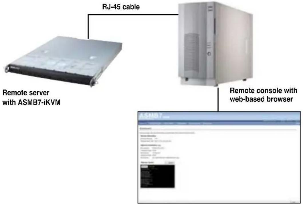
The ASMB7-iKVM server management board installed on the remote server connects to a local/central server via direct LAN connection or through a network hub. Below are the supported server management configurations.
Direct LAN connection
LAN connection through a network hub

flowchart
graph TD
    A["Remote server with ASMB7-iKVM"] --> B["Hub or router"]
    B --> C["Remote console with web-based browser"]
This chapter provides instructions on how to install the board to the server system and install the utilities that the board supports.
Installation
2.1 Before you proceed
Take note of the following precautions before you install the server management board to the remote server system.

- Unplug the server system power cord from the wall socket before touching any component.
- Use a grounded wrist strap or touch a safely grounded object or to a metal object, such as the power supply case, before handling components to avoid damaging them due to static electricity.
- Hold components by the edges to avoid touching the ICs on them.
- Whenever you uninstall any component, place it on a grounded antistatic pad or in the bag that came with the component.
- Before you install or remove any component, ensure that the power supply is switched off or the power cord is detached from the power supply. Failure to do so may cause severe damage to the motherboard, peripherals, and/or components.
2.2 Hardware installation
To install the server management board:
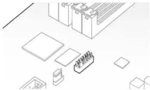
- Locate the Baseboard Management Card header on the motherboard.
natural_image
Isometric line drawing of various electronic components and devices (no text or symbols)- Orient and press the Management Card in place.

natural_image
Isometric view of a device with a blue arrow pointing to a component labeled '3' (no text or symbols present)
The motherboard illustration is for reference only. The motherboard layout and appearance may vary depending on the model, but the installation steps remain the same.
- Press the board firmly until it is completely seated in place.
- Insert the LAN cable plug to the LAN port for server management.

Refer to the Appendix for the location of the LAN port for server management.
- For direct LAN configuration, connect the other end of the LAN cable to the local/central server LAN port.
For connection to a network hub or router, connect the other end of the LAN cable to the network hub or router.
- Ensure the VGA, USB, PS/2 cables are corrected, then connect the power plug to a grounded wall socket.

Everytime after the AC power is re-plugged, you have to wait for about 70 seconds for the system power up.
2.3 Firmware update and IP configuration
You need to update the ASMB7-iKVM firmware and configure IP source before you start using the ASMB7-iKVM board.
- Insert the support CD into the optical drive.
- Restart the remote server, then press
during POST to enter the BIOS setup. - Go to Boot menu and set the Boot Device Priority item to [CD-ROM].
- When finished, press
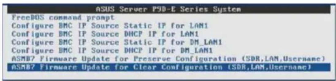
to save your changes and exit the BIOS setup. - On reboot, the main menu appears. Select ASMB7-iKVM Firmware Update for Clear Configuration, and press
to enter the sub-menu.
- A confirmation message appears, asking whether you want to update the firmware or not. Select
to update.

The firmware updating process starts.
- When the update process is completed, the following screen appears.
Preserving Env Variables... done
Uploading Firmware Image : 100%... done
Flashing Firmware Image : 100%... done
Verifying Firmware Image : 100%... done
Setting Env variables ... done
Resetting the firmware.....
Please wait for 70 seconds to initialize firmware
Delay 70 Seconds
Press any key to continue . . .

You may update firmware from the web-based user interface. Refer to page 4-13 for details.
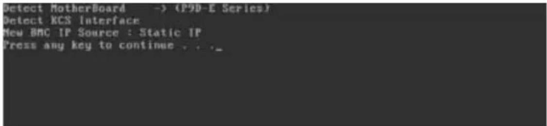
2.3.2 Configure BMC IP source static IP
- Repeat the step 1-4 in the previous sub-section.
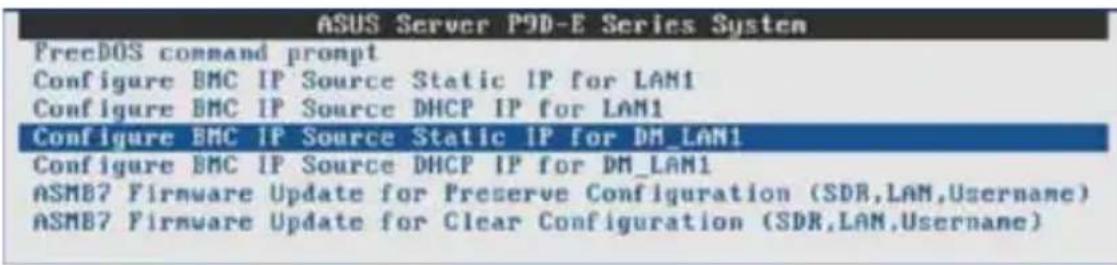
- On reboot, the main menu appears. Select Configure BMC IP Source Static IP for LAN1 (or DM_LAN1), and press
to enter the sub-menu.
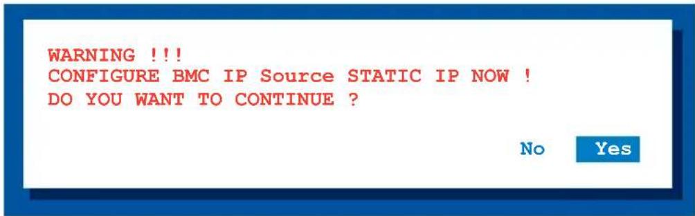
- A confirmation message appears, asking if you want to configure the BMC IP source static IP now. Select
to continue.
- When the configuration is completed, the below screen appears.
- Go to BIOS menu to set the IP. Refer to section 2.4 for IP settings in BIOS menu.
2.3.3 Configure BMC IP source DHCP
- Repeat the step 1-4 in the previous sub-section.
- On reboot, the main menu appears. Select Configure BMC IP Source DHCP for LAN1 (or DM_LAN1), and press
to enter the sub-menu.

- A confirmation message appears, asking if you want to configure the BMC IP source DHCP now. Select
to continue.

- When the configuration is completed, the below screen appears.
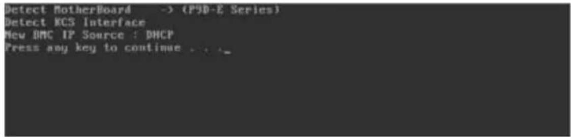
- Then you can get IP from DHCP server.
2.4 BIOS configuration
You need to adjust the settings in the BIOS setup of the remote server for correct configuration and connection to the central server.

- Update the remote server BIOS file following the instructions in the motherboard/system user guide. Visit the ASUS website (www.asus.com) to download the latest BIOS file for the motherboard.
- The BIOS setup screens shown in this section are for reference purposes only, and may not exactly match what you see on your screen.
2.4.1 Running the BIOS BMC configuration
To configure the BMC in the BIOS:
- Restart the remote server, then press
during POST to enter the BIOS setup. - Go to the Server Mgmt menu, then select the BMC network configuration sub-menu. Use this sub-menu to configure the BMC settings.
- When finished, press
to save your changes and exit the BIOS setup.
2.4.2 BMC network configuration
Allows you to set the BMC LAN Parameter settings.
![Aptio Setup Utility - Copyright (C) 2013 American Megatrends, Inc. Main Advanced Server Mgt Event Logs Boot Monitor Security Tool Exit DMC Firmware Version : 1.04 DS Watchdog Timer [Disabled] ► System Event Log ► EMC Network Configuration ► IPv6 DMC Network Configuration Configure BMC network parameters **: Select Screen TI: Select Item Enter: Select +/-: Change Opt. F1: General Help F2: Previous Values F5: Optimized Defaults F10: Save & Exit ESC: Exit Version 2.15.1236. Copyright (C) 2013 American Megatrends, Inc.](/content/2026/05/841568/images/2735c5aa56c90bb55b5e00cde679ece5c33316da1a2c4a6b681c4b21e6ce4048.jpg)
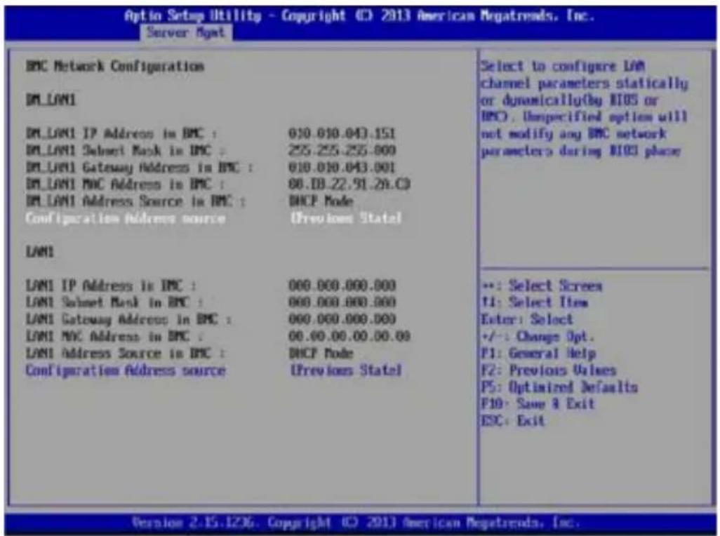
Configuration Source [Previous State]
Allows you to select the IP address source type. Set the LAN channel parameters statically or dynamically.
![ASUS ASMB7-IKVM - Configuration Source [Previous State] - 1](/content/2026/05/841568/images/c19d8e2f99d51d9293f06ca8372b3c883cc253bbf5851532fded84238fed36af.jpg)
The following items are available when you set Configuration Source to [Static].
Station IP Address
Allows you to set the BMC IP address.
Subnet Mask
Allows you to set the BMC subnet mask. We recommend that you use the same Subnet Mask you have specified on the operating system network for the used network card.
Gateway IP Address
Allows you to set the Gateway IP address.
2.4.3 System Event Log
Allows you to view all the events in the BMC event log. It will take a maximum of 15 seconds to read all the BMC SEL records.
![Options Setup Utility - Copyright © 2013 American Negatrends, Inc. Server Agent Enabling/Disabling Options SEL Components [Disabled] Erasing Settings Erase SEL [No] When SEL is Full [No Nothing] NOTE: All values changed here do not take effect until computer is restarted. Change this to enable or disable all features of System Event Logging during boot. +: Select Screen II: Select Item Enter: Select +/-: Change Opt. F1: General Help F2: Previous Values F5: Optimized Defaults F10: Save & Exit ESC: Exit Version 2.15.1236. Copyright © 2013 American Negatrends, Inc.](/content/2026/05/841568/images/221e7486f8c6137c10f094840df84bb9912182cf85499e287f8639815c2f5bf8.jpg)
SEL Components [Disabled]
Allows you to enable or disable all features of system event log during booting.
![ASUS ASMB7-IKVM - SEL Components [Disabled] - 1](/content/2026/05/841568/images/b9bbf87c5b20989a12e051dca3e07b0dba3423d28bc9111ed186e1acaccc191a.jpg)
The following items become configurable when you set SEL Components to [Enabled].
Erase SEL [No]
Allows you to select how to erase SEL.
Configuration options: [No] [Yes, On next reset] [Yes, On every reset]
When SEL is Full [Do Nothing]
Allows you to select what to do to a full SEL.
Configuration options: [Do Nothing] [Erase Immediately]
2.4.4 IPv6 BMC Network Configuration
Displays the LAN channel parameters and allows you to configure the IPv6 BMC LAN settings.
![Aptio Setup Utility - Copyright (C) 2011 American Megatrends, Inc. Main Advanced Server Hgmt Event Loss Boot Monitor Security Tool Exit BMC Firmware Version : 1.08 OS Watchdog Timer [Disabled] OS Mtd Timer Tircout [10 minutes] OS Mtd Timer Policy [Reset] ► System Event Log ► BNC Network Configuration ► IPv6 BNC Network Configuration Configure IPv6 BNC network parameters](/content/2026/05/841568/images/3c41be45c4a5221447904d84b2148c3b9100bcb062556e172ec655566f5d6e4d.jpg)
![Aptid Setup Utility - Copyright (C) 2011 American Netatrends, Inc. Server Hgmt IPv6 EMC Network Configuration IPv6 EMC OMLLAN1: DN_LAN1 IP Address In BMC : -> 2002:000:0:0:F101:0:0:0:1398 DN_LAN1 Prefix Length In BMC : 64 DN_LAN1 Gateway Address In BMC : -> 0:0:0:0:0:0:0:0:0 DN_LAN1 MAC Address In BMC : 00.E0.1B.65.0C.30 DN_LAN1 Address Source In BMC : DHCP Mode IPv6 EMC OM_LAN1 IP Address Source [Previous State] IPv6 EMC Lan1: Lan1 IP Address in BMC : -> 2002:000:0:F101:0:0:31:4049 Lan1 Prefix Length In BMC : 100 Lan1 Gateway Address In BMC : -> 0:400:0:0:0:BOR1:3940:0 Lan1 MAC Address in BMC : 00.00.00.00.00.00 Lan1 Address Source In BMC : DHCP Mode IPv6 EMC Lan1 IP Address Source [Previous State] Select to configure LAN channel parameters statically or dynamically(by BIOS or EMC) ←: Select Screen ↑↓: Select Item Enter: Select →←: Change Opt. F1: General Help F2t Previous Values FSt Optimized Defaults F10: Save & Exit ESC: Exit Version 2.14.1219, Copyright (C) 2011 American Netatrends, Inc.](/content/2026/05/841568/images/9ca0c9ec6b271054c9e80fc43c941e8e556744b8432fc93f4056c532e796b4db.jpg)
IPv6 BMC DM LAN1 IP Address Source [Previous State]
Allows you to select the IP address source type and set the LAN channel parameters statically or dynamically. Configuration options: [Previous State] [Static] [Dynamic-Obtained by BMC running DHCP]

The following items are available when you set IPv6 BMC DM_LAN1 IP Address Source to [Static].
IPv6 BMC DM\_LAN1 IP Address
Allows you to set the IPv6 BMC DM_LAN1 IP address.
IPv6 BMC DM\_LAN1 IP Prefix Length
Allows you to set the IPv6 BMC DM_LAN1 IP Prefix length.
IPv6 BMC DM\_LAN1 Default Gateway
Allows you to set the IPv6 BMC DM_LAN1 Gateway IP address.
IPv6 BMC Lan1 IP Address Source [Previous State]
Allows you to select the IP address source type and set the LAN channel parameters statically or dynamically. Configuration options: [Previous State] [Static][Dynamic-Obtained by BMC running DHCP]
![ASUS ASMB7-IKVM - IPv6 BMC Lan1 IP Address Source [Previous State] - 1](/content/2026/05/841568/images/5c21b232641b0ea5cde48ca73955bc408b0e1eca2750aa4113551645d3ab37fc.jpg)
The following items are available when you set IPv6 BMC Lan1 IP Address Source to [Static].
IPv6 BMC Lan1 IP Address
Allows you to set the IPv6 BMC Lan1 IP address.
IPv6 BMC Lan1 IP Prefix Length
Allows you to set the IPv6 BMC Lan1 IP Prefix length.
IPv6 BMC Lan1 Default Gateway
Allows you to set the IPv6 BMC Lan1 Gateway IP address.
2.5 Running the ASMC7 utility
The ASMC7 utility allows you to update the ASMB7-iKVM firmware, configure the LAN setting for the remote server and change the user name/password in DOS environment. This utility is available from the support CD that came with the package.
To run the ASMC7 utility:
- Insert the support CD into the optical drive.
- Restart the remote server, then press
during POST to enter the BIOS setup. - Go to Boot menu and set the Boot Device Priority item to [CD-ROM].
- When finished, press
to save your changes and exit the BIOS setup. - On reboot, the main menu appears. Select FreeDOS command prompt, and then press
.

- When the C:> prompt appears, type ASMC7 -?, then press
to display the ASMC7 Utility Help Menu. The screen appears as shown.
![! ASUS Server Management Card Utility 7.00 Help Menu Usage: ASMC7 -kcs[smic/ht/pci_smic] NetFn command data.... ASMC7 -bmc_ip_source source(1:Static, 2:DHCP) ASMC7 -bmc_ip ip_addr(10.10.10.20) ASMC7 -bmc_mask ip_mask(255.255.255.8) ASMC7 -bmc_gateway ip_addr(10.10.10.254) ASMC7 -ipv6_source source(1:Static, 2:DHCP) ASMC7 -ipvb ipvb_addr(2001:8db8:1234:5678:8769:e1cb:aabb:ccdd) ASMC7 -ipv6_prefix prefix_length(64) ASMC7 -pet_ip_mac ip_addr(10.10.10.20) mac_addr(818283848586) ASMC7 -bmc_ip_g_lan1 source(1:Static, 2:DHCP) ASMC7 -bmc_ip_lan1 ip_addr(10.10.10.20) ASMC7 -bmc_mask_lan1 ip_mask(255.255.255.8) ASMC7 -bmc_g_lan1 ip_addr(10.10.10.254) ASMC7 -ipv6_s_lan1 source(1:Static, 2:DHCP) ASMC7 -ipv6_lan1 ip_addr(2001:84b8:1234:5678:8769:e1cb:aabb:ccdd) ASMC7 -ipv6_pre_lan1 prefix_length(64) ASMC7 -pet_ip_m_lan1 ip_addr(10.10.10.20) mac_addr(818283848586)](/content/2026/05/841568/images/930e3b776e389a631828a02979b3416acc18608f1d13fcb6994eabb1320211d5.jpg)
Press any key to see next page.
![ASMC7 -adm_name new_name_string ASMC7 -user_name new_name_string ASMC7 -adm_password new_adn_password ASMC7 -user_password new_user_password ASMC7 -sol_baud 57688[9688/19288/30488/57688/115288] ASMC7 -bnc_info ASMC7 -fru -view fru_id ASMC7 -fru -load fru_file ASMC7 -fru -save fru_id fru_file ASMC7 -sel -clear C:\>](/content/2026/05/841568/images/568e963cdfb114c7a38c937a728ca2f02b17ae14035e0f3a177b42ce25ccfb3a.jpg)
ASMC7 Help Menu options
| Options Description | |
| -kcs[smic/bt/pci_smic] NetFn command data.... | Send IPMI command |
| -bmc_ip_source source[1: Static, 2: DHCP] Set the IP source | |
| -bmc_ip [ip_addr](e.g., bmc_ip 10.10.10.20) | Write the BMC IP address for dedicated LAN |
| -bmc_mask [ip_mask](e.g., bmc_mask 255.255.255.0) | Write the subnet mask for dedicated LAN |
| -bmc_gateway [ip_addr](e.g., bmc_gateway 10.10.10.254) | Write the gateway address for dedicated LAN |
| -pet_ip_mac [ip_addr] [mac_addr](e.g., pet_ip_mac 10.10.10.20 010203040506) | Write the PET destination IP and MAC addresses for dedicated LAN |
| -bmc_ip_s_lan1 source[1: Static, 2: DHCP] Set the IP source for shared LAN | |
| -bmc_ip_lan1 [ip_addr](e.g., bmc_ip 10.10.10.20) | Write the BMC IP address for shared LAN |
| -bmc_mask_lan1 [ip_mask](e.g., bmc_mask 255.255.255.0) | Write the subnet mask for shared LAN |
| -bmc_g_lan1 [ip_addr](e.g., bmc_gateway 10.10.10.254) | Write the gateway address for shared LAN |
| -pet_ip_m_lan1 [ip_addr] [mac_addr](e.g., pet_ip_mac 10.10.10.20 010203040506) | Write the PET destination IP and MAC addresses for shared LAN |
| -adm_name new_name_string | Change the administration name |
| -user_name new_name_string | Change the user name |
| -adm_password new_adm_password | Change the administration password |
| -user_password new_user_password | Change the user password |
| -sol_baud [baud rate](e.g., sol_baud 57600) | Set the communication Baud rate |
| -bmc_info Displays the BMC and PET IP and | MAC addresses |
| -fru -view fru_id Displays the system FRU information | |
| -fru -load fru_file Update system FRU data from file | |
| -fru -save fru_id fru_file Save system FRU data to file | |
| -sel -clear Clear system event log | |
2.5.1 Configuring the LAN controller
Before you can establish connection to the ASMB7-iKVM board, you must configure the LAN port for server management used by the remote server to connect to the local/central server.
To configure the LAN port of the remote server:
- Run the ASMC7 utility from the support CD following the instructions in the previous section.
- Set IP source:
(a) Type ASMC7 -bmc_ip_source 1 if you want to set a static IP address.
(b) Type ASMC7 -bmc_ip_source 2 if you want to get IP from DHCP server.
- Type ASMC7 -bmc_ip xxx.xxx.xxx.xxx, then press
to assign any IP address to the remote server LAN port (if necessary). The screen displays the request and response buffer. Write the remote server IP address in a piece of paper for reference.
c:\>ASMC7 -bmc_ip 10.10.10.243
Detect MotherBoard -> (Z9PE-D16 Series)
Detect KCS Interface
New BMC IP : 10.10.10.243
c:\>
When finished, the utility returns to the DOS prompt.

Make sure that the assigned IP address for both remote and local/central servers are in the same subnet. You can use the network settings utility in your OS to check.
- Configure your (a) subnet mask and (b) gateway address if necessary.
(a) Type ASMC7 -bmc_mask xxx.xxx.xxx.xxx (your subnet mask encoded in hexadecimal system)
(b) Type ASMC7 -bmc_gateway xxx.xxx.xxx.xxx (your gateway address encoded in hexadecimal system)
-
Restart the remote server, enter the BIOS setup, then boot from the hard disk drive.
-
Adjust the local/central server network settings, if necessary.
2.5.2 Configuring the user name and password
You may change your user name and password from the ASMC7 utility.
To change the user name and password:
- Follow steps 1-5 on page 2-11.
- When the C:> prompt appears, type ASMC7 -user_name xxxxx, then press
to change the user name.
C:\>ASMC7 -user_name super
Detect MotherBoard -> (Z9PE Series)
Detect KCS Interface

Change User Name to super
C:\>
- Type ASMC7 -user_password xxxxxxxx, then press
to change the password. - Restart the remote server, enter the BIOS setup, then boot from the hard disk drive.
This chapter shows you how to set-up the ASUS Host Management Controller that the server management board supports.
ASUS Host
Management Controller Set-up
3.1 ASUS Host Management Controller Setup
The ASUS Host Management Controller Setup utility provides precise configuration and basic functions including System Event Log (SEL) generation and System Data Record (SDR) reading in DOS mode.
This utility also supplies configuration sequences for the type of host interface as well as direct real-time monitoring of system information including CPU temperature(s), fan speeds and system voltages.
3.1.1 Installing and launching the ASUS Host Management Controller Setup utility
To install the ASUS Host Management Controller Setup utility:
- Boot the server in DOS mode using the support CD.
- At the prompt, type ASMC7, then press
to display the ASMC7 Utility Help Menu. The screen appears as shown.
C:>ASMC7
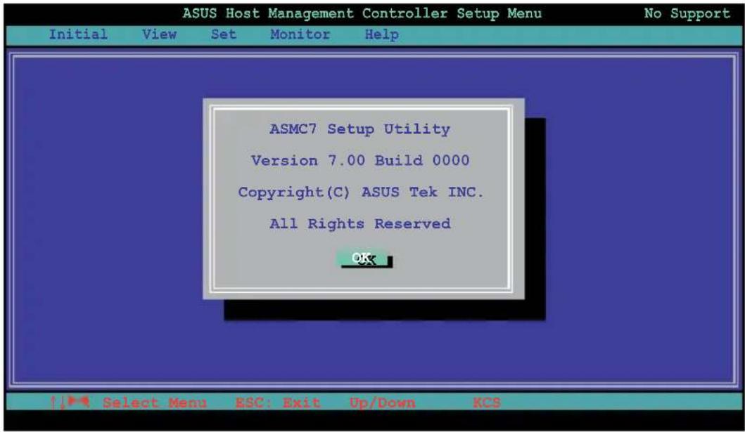
- The main utility screen appears. Press
.
3.1.2 Command fields
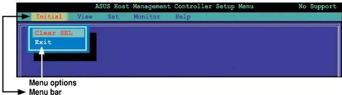
The utility menu bar has five commands: Initial, View, Set, Monitor and Help. You can select a command using the left or right arrow button on the keyboard. After selecting a command, use the down arrow key to display available options. Select a command, then press
3.1.3 Initial
The Initial command allows you to clear the SEL information or exit the utility.
Go to Initial command, then select Clear SEL to empty all System Event Log information for a refresh set of data records. Use the Clear SEL command when creating a new log that begins at an exact time for precise system monitoring.
Select Exit to close the utility and return to the DOS prompt.

3.1.4 View
The View command displays the Baseboard Management Controller (BMC) data record including the System Event Log (SEL), the System Data Record (SDR), and general BMC information.

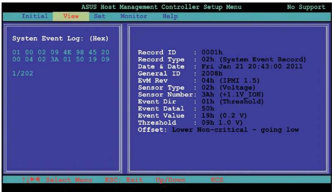
To view the System Event Log (SEL):
- Select BMC SEL from the View command option, then press
. A complete list of system event records appear on the left pane. The right pane displays the SEL information.
The number on the left bottom of the window shows the system event displayed in the right window pane over the total number of system events in the remote host.
- Use the down arrow key to display the next sensor event.
- Press
to return to the main screen.
To view the System Data Record (SDR):
- Select BMC SDR from the View command option, then press
. A complete list of data records appears on the left pane. The right pane displays the sensor data information.
The number on the bottom left of the screen indicates the data record displayed in the right window pane over the total number of sensor data records in the remote host.

- Use the down arrow key to display the next sensor data record.
- Press
to return to the main screen.
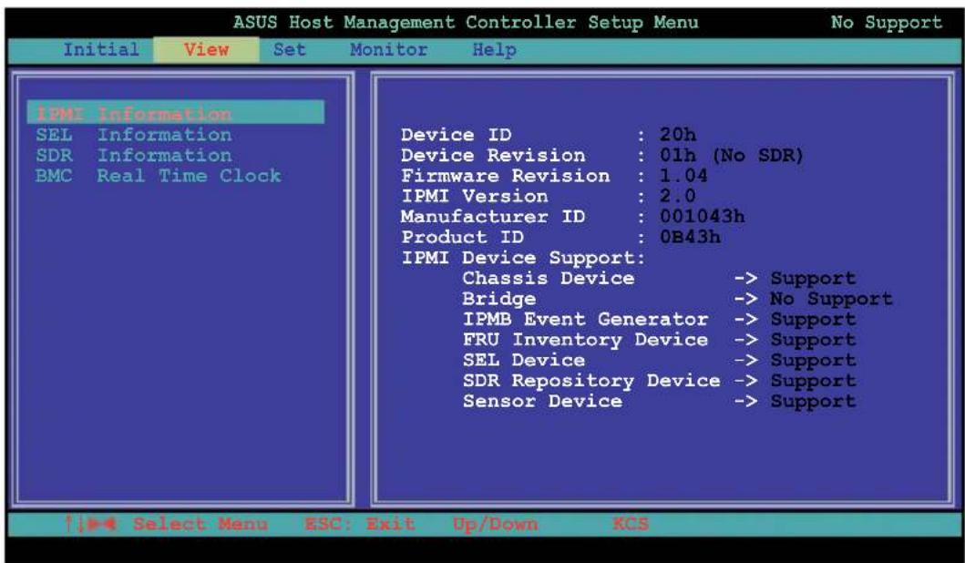
To view the BMC information:
- Select BMC Info from the View command option, then press
. A list of BMC information appears on the left pane. - Use the down arrow button to select a BMC information. The BMC information is displayed in the right pane.
- Press
to return to the main screen.
3.1.5 Set
The Set command controls the host interface type and the correct BMC time.

To select the host interface:
-
Select Host Interface from the Set command option, then press
. The screen displays the host interfaces supported by the server management board. -
Use the down arrow button to select a host interface, then press
.
![ASUS Host Management Controller Setup Menu Initial View Set Monitor Help Set Host Interface [-] KCS Interface [ ] SMIC Interface [ ] BT Interface [ ] PCI Interface [ ] KCS2 Interface OK Cancel Select Menu ESC: Exit Up/Down KCS](/content/2026/05/841568/images/cdfe7d53b0e983240154031259567b1504dd1f1aefac4af4e6f6c6f1d15186ad.jpg)
You can select from the following interfaces:
KCS Interface - Keyboard Controller Style
SMIC Interface - Server Management Interface Chip
BT Interface - Block Transfer
PCI Interface - Peripheral Component Interconnect
KCS2 Interface - Keyboard Controller 2 Style
- When finished, press
to return to the main screen.
To set the BMC Timer:
- Select BMC Timer from the Set command option, then press
. - Set the BMC IPMI timer to the current system time.
- When finished, press
to return to the main screen.
3.1.6 Monitor
The Monitor command displays real-time data on the remote server system and CPU temperatures, voltages, and fan speeds.

To display a remote server information:
- Select a sensor from the Monitor command options, then press
. A list of server information appears on the left pane. - Use the down arrow button to select a monitor information. The selected monitor information details are displayed in the right pane.

- Press
to return to the main screen.
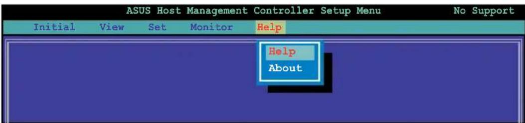
3.1.7 Help
The Help command displays the available utility options, utility version, and copyright information.
This chapter tells you how to use the web-based user interface that the server management board supports.
Web-based user interface
4.1 Web-based user interface
The web-based user interface allows you to easily monitor the remote server's hardware information including temperatures, fan rotations, voltages, and power. This application also lets you instantly power on/off or reset the remote server.
To enter the Web-based user interface:
- Enter the BIOS Setup during POST.
- Go to the Advanced Menu > Runtime Error Logging > CPU II0 Bridge Configuration > Launch Storage OpROM, then press
. - Set Launch Storage OpROM to [Enabled].
- Go to the Server Mgmt Menu > BMC network configuration > Configuration Address source, then press
. - Enter the IP Address in BMC, Subnet Mask in BMC and Gateway Address in BMC.
- Press
to save your changes and exit the BIOS Setup.

You should install JRE on remote console first before using web-based management. You can find JRE from the folder JAVA of the ASMB7-iKVM support CD. You can also download JRE from http://www.oracle.com/technetwork/java/javase/downloads/index.html
4.1.1 Logging in the utility
- Ensure that the LAN cable of the computer is connected to the LAN port of the remote server.
- Open the web browser and type in the same IP address as the one in the remote server.
- The below screen appears. Enter the default user name (admin) and password (admin). Then click Login.

4.1.2 Using the utility
The web-based graphics user interface displays when you login in the utility successfully.
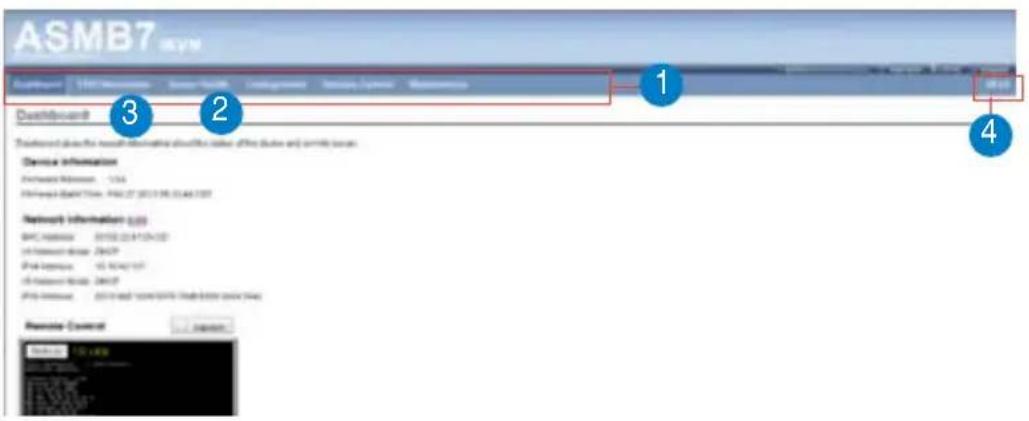
- Menu bar: Click a menu to display available function lists.
- Function list: Click each function key to start using its specific functions.
- Function title: Displays the function title.
- Help menu: Click to display the brief description of the selected function.
4.2 FRU Information
This section contains detailed information for various FRU devices present in this system.

4.3 Server Health
This section contains the data related to the server health, such as the Sensor Readings, Event log and System and Audit Log. Click each function key to start using its specific functions

4.3.1 Sensor Readings (with Thresholds)
The Sensor Readings page displays the system sensor information, including readings and status.

- Select a sensor type category: Allows you to select the type of sensor readings to be displayed in the list.
- Status List: Show the type of sensor readings list that you selected in the drop-down list.
- Live Widget: Click to enable or disable the Live Widget function.
4.3.2 Event Log
The Event Log page displays a table of system event log.

- Select an event log category: Allows you to select the type of events to be displayed in the list.
- Clear Event Log: Click to clear the event log.
4.4 Configuration
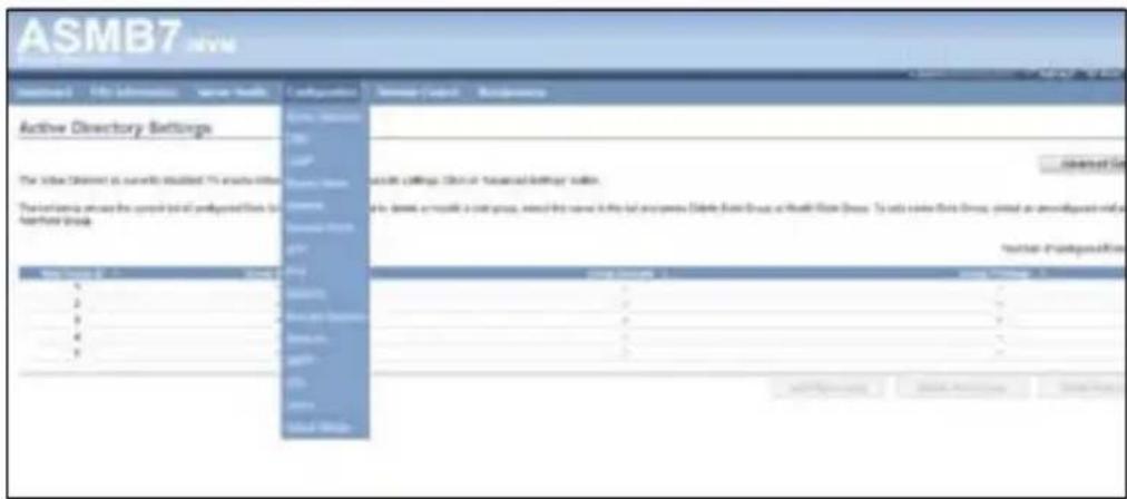
This section allows you to configure the system settings. Click each function key to start using its specific functions
4.4.1 Active Directory
An active directory does a variety of function including the ability to provide the information on objects, helps organize these objects for easy retrieval and access, allows access by users and administrators, and allows the administrators to set security up for the directory. To open Active Directory Settings page, click Configuration > Active Directory from the main menu. A sample screenshot of Active Directory Settings Page is shown in the screenshot below.

-
Role Group ID: The name that identifies the role group in the Active Directory. Role Group Name is a string of 255 alpha-numeric characters. Special symbols hyphen and underscore are allowed.
-
Add Role Group: To add a new role group to the device.
-
Modify Role Group: To modify that role group. Alternatively, double click on the configured slot.
-
Delete Role Group: To delete an existing Role Group.
-
Advanced Settings: This option is used to configure Active Directory Advanced Settings. Options are Enable Active Directory Authentication, User Domain name, Time Out and up to three Domain Controller Server Addresses.
Procedure:
Entering the details in Advanced Active Directory Settings Page
- Click on Advanced Settings to open the Advanced Active Directory Settings Page.

-
In the Active Directory Settings Page, enter the following details.
-
Active Directory Authentication: To enable/disable Active Directory, check or uncheck the Enable checkbox respectively.

If you have enabled Active Directory Authentication, enter the required information to access the Active Directory server.
-
Specify the Domain Name for the user in the User Domain Name field. e.g. asus.com
-
Specify the time (in seconds) to wait for Active Directory queries to complete in the Time Out field.

-
Default Time out value: 120 seconds.
-
Range from 15 to 300 allowed.
-
Configure IP addresses in Domain Controller Server Address1, Domain Controller Server Address2 & Domain Controller Server Address3.
-
Click Save to save the entered settings and return to Active Directory Settings Page.
-
Click Cancel to cancel the entry and return to Active Directory Settings Page.
To add a new Role Group
- In the Active Directory Settings Page, select a blank row and click Add Role Group to open the Add Role group Page as shown in the screenshot below.

- In the Role Group Name field, enter the name that identifies the role group in the Active Directory.

- Role Group Name is a string of 255 alpha-numeric characters.
-
Special symbols hyphen and underscore are allowed.
-
In the Role Group Domain field, enter the domain where the role group is located.

- Domain Name is a string of 255 alpha-numeric characters.
-
Special symbols hyphen, underscore and dot are allowed.
-
In the Role Group Privilege field, enter the level of privilege to assign to this role group.
- Click Add to save the new role group and return to the Role Group List.
- Click Cancel to cancel the settings and return to the Role Group List.
To Modify Role Group
- In the Advanced Directory Settings Page, select the row that you wish to modify and click Modify Role Group.
- Make the necessary changes and click Save.
To Delete a Role Group
In the Advanced Directory Settings Page, select the row that you wish to delete and click Delete Role Group.
4.4.2 DNS
The page allows you to manage DNS settings of the device.

4.4.3 LDAP
The Lightweight Directory Access Protocol (LDAP) is an application protocol for querying and modifying data of directory services implemented in Internet Protocol (IP) networks. If you have an LDAP server configured on your network, you can use it as an easy way to add, manage and authenticate MegaRAC® card users. This is done by passing login requests to your LDAP Server. This means that there is no need to define an additional authentication mechanism, when using the MegaRAC card. Since your existing LDAP Server keeps an authentication centralized, you will always know who is accessing the network resources and can easily define the user or group-based policies to control access.
To open LDAP Settings page, click Configuration > LDAP from the main menu. A sample screenshot of LDAP Settings Page is shown in the screenshot below. LDAP Settings Page

-
Advanced Settings: To configure LDAP Advanced Settings. Options are Enable LDAP Authentication, IP Address, Port and Search base.
-
Add Role Group: To add a new role group to the device. Alternatively, double click on a free slot to add a role group.
-
Modify Role Group: To modify the particular role group.
-
Delete Role Group: To be delete a role group from the list.
Procedure
Entering the details in Advanced LDAP Settings Page
- In the LDAP Settings Page, click Advanced Settings. A sample screenshot of LDAP Settings page is given below.

- To enable/disable LDAP Authentication, check or uncheck the Enable checkbox respectively.

During login prompt, use username to login as an ldap Group member.
- Enter the IP address of LDAP server in the IP Address field.

-
IP Address made of 4 numbers separated by dots as in 'xxx.xxx.xxx.xxx'.
-
Each Number ranges from 0 to 255.
-
First Number must not be 0.
-
Supports IPv4 Address format and IPv6 Address format.
-
Specify the LDAP Port in the Port field.

Default Port is 389. For Secure connection, default port is 636.
-
Enter the Search Base. The Search base tells the LDAP server which part of the external directory tree to search. The search base may be something equivalent to the organization, group of external directory.
-
Click Save to save the settings.
-
Click Cancel to cancel the modified changes.
To add a new Role Group
- In the LDAP Settings Page, select a blank row and click Add Role Group to open the Add Role group Page as shown in the screenshot below.
2 In the Role Group Name field, enter the name that identifies the role group. - In the Role Group Search Base field, enter the path from where the role group is located to Base DN.

- Search Base is a string of 255 alpha-numeric characters.
-
Special symbols hyphen, underscore and dot are allowed.
-
In the Role Group Privilege field, enter the level of privilege to assign to this role group.
-
Click Add to save the new role group and return to the Role Group List.
-
Click Cancel to cancel the settings and return to the Role Group List.
To Modify Role Group
- In the LDAP Settings Page, select the row that you wish to modify and click Modify Role Group.
- Make the necessary changes and click Save.
To Delete a Role Group
In the LDAP Settings Page, select the row that you wish to delete and click Delete Role Group.
4.4.4 Mouse Mode
The Mouse Mode page allows you to select the mouse mode.

- Save: Select the desired mouse mode, and then click Save to apply the setting.
4.4.5 Network
The Network page allows you to configure the network settings.

-
MAC Address: Select whether to obtain the IP address automatically or manually configure one.
-
IP Address/Subnet Mask/Default Gateway: If you configure a static IP, enter the requested address, subnet mask and gateway in the given field.
4.4.6 Network Bond
This page allows you to enable or disable networking bonding feature and configure the default interfaces.

4.4.7 NTP
This page allows you to configure the NTP server or view and modify the device's Date and Time settings.

4.4.8 PEF
Platform Event Filtering (PEF) provides a mechanism for configuring the BMC to take selected actions on event messages that it receives or has internally generated. These actions include operations such as system power-off, system reset, as well as triggering the generation of an alert. A PEF implementation is recommended to provide at least 16 entries in the event filter table. A subset of these entries should be pre-configured for common system failure events, such as over-temperature, power system failure, fan failure events, etc.
To open PEF Management Settings page, click Configurations > PEF from the main menu. A sample screenshot of PEF Management Settings Page is shown in the screen shot below.

- PEF ID: This field displays the ID for the newly configured PEF entry (read-only).
- Filter configuration: Check box to enable the PEF settings.
- Event Filter Action: Check box to enable PEF Alert action. This is a mandatory field.
- Event Severity: To choose any one of the Event severity from the list.
- Sensor Name: To choose the particular sensor from the sensor list.
- Add: To add the new event filter entry and return to Event filter list.
- Modify: To modify the existing entries.
- Cancel: To cancel the modification and return to Event filter list.
Procedure:
- Click the Event Filter Tab to configure the event filters in the available slots
- To Add an Event Filter entry, select a free slot and click Add to open the Add event Filter entry Page. A sample screenshot of Add Event Filter Page is in seen the screenshot below.

-
In the Event Filter Configuration section,
-
PEF ID displays the ID for configured PEF entry (read-only).
- In filter configuration, check the box to enable the PEF settings.
-
In Event Severity, select any one of the Event severity from the list.
-
In the Filter Action configuration section,
- Event Filter Action is a mandatory field and checked by default, which enable PEF Alert action (read-only).
- Select any one of the Power action either Power down, Power reset or Power cycle from the drop down list
- Choose any one of the configured alert policy number from the drop down list.

Alert Policy has to be configured - under Configuration->PEF->Alert Policy.
-
In the Generator ID configuration section,
-
Check Generator ID Data option to fill the Generator ID with raw data.
- Generator ID 1 field is used to give raw generator ID1 data value.
- Generator ID 2 field is used to give raw generator ID2 data value.

In RAW data field, to specify hexadecimal value prefix with '0x'.
Alert Policy Tab
This page is used to configure the Alert Policy and LAN destination. You can add, delete or modify an entry in this page.

The fields of PEF Management – Alert Policy Tab are explained below.
- Policy Entry #: Displays Policy entry number for the newly configured entry (read-only).
- Policy Number: Displays the Policy number of the configuration.
- Policy Configuration: To enable or disable the policy settings.
- Policy Set: To choose any one of the Policy set values from the list.
0 - Always send alert to this destination.
1 - If alert to previous destination was successful, do not send alert to this destination. Proceed to next entry in this policy set.
2 - If alert to previous destination was successful, do not send alert to this destination. Do not process any more entries in this policy set.
3 - If alert to previous destination was successful, do not send alert to this destination. Proceed to next entry in this policy set that is to a different channel.
4 - If alert to previous destination was successful, do not send alert to this destination. Proceed to next entry in this policy set that is to a different destination type.
-
Channel Number: To choose a particular channel from the available channel list.
-
Destination Selector: To choose a particular destination from the configured destination list.

LAN Destination has to be configured - under Configuration->PEF->LAN Destination.
- Add: To save the new alert policy and return to Alert Policy list.
- Modify: To modify the existing entries.
- Cancel: To cancel the modification and return to Alert Policy list.
Procedure:

- In the Alert Policy Tab, select the slot for which you have to configure the Alert policy. That is, In the Event Filter Entry Page, if you have chosen Alert Policy number as 4, you have to configure the 4th slot (the slot with Policy Number 4) in the Alert Policy Tab.
- Select the slot and click Add to open the Add Alert Policy Entry Page as shown in the screenshot below.
- Policy Entry # is a read only field.
- Select the Policy Number from the list.
- In the Policy Configuration field, check Enable if you wish to enable the policy settings.
- In the Policy Set field, choose any of the Policy set from the list.
- In the Channel Number field, choose particular channel from the available channel list.
- In the Destination Selector field, choose particular destination from the configured destination list.

LAN Destination has to be configured under Configuration->PEF->LAN Destination. That is if you select the number 4 for destination selector in Alert Policy Entry page, then you have to configure the 4th slot (LAN Destination Number 4) in the LAN Destination tab.
- In the Alert String field, enable the check box if the Alert policy entry is Event Specific.
- In the Alert String Key field, choose any one value that is used to look up the Alert String to send for this Alert Policy entry.
- Click Add to save the new alert policy and return to Alert Policy list.
- Click Cancel to cancel the modification and return to Alert Policy list.
- In the Alert Policy list, to modify a configuration, select the slot to be modified and click Modify.
- In the Modify Alert Policy Entry Page, make the necessary changes and click Modify.
- In the Alert Policy list, to delete a configuration, select the slot and click Delete.
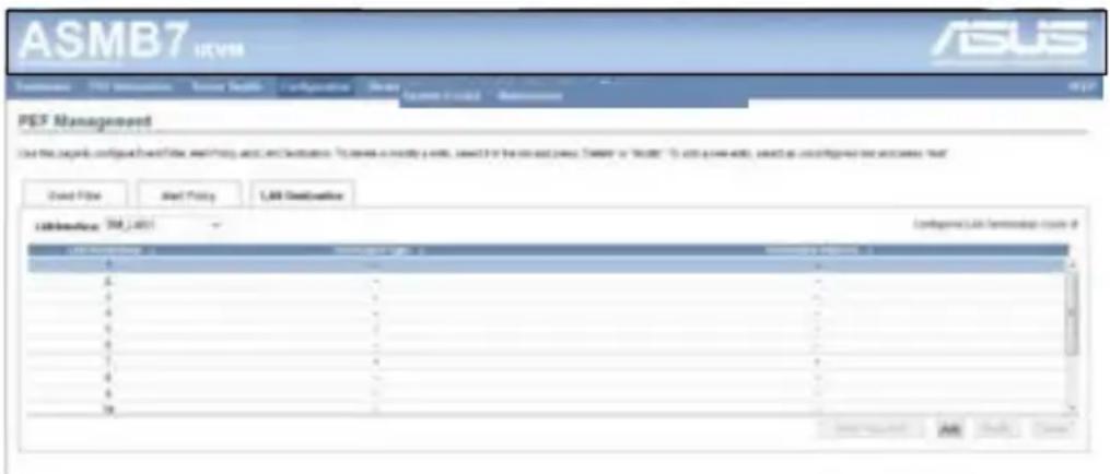
PEF Management LAN Destination Page
This page is used to configure the Event filter, Alert Policy and LAN destination. A sample screenshot of PEF Management LAN Destination Page is given below.
The fields of PEF Management – LAN Destination Tab are explained below.
- LAN Destination: Displays Destination number for the newly configured entry (read-only).
- Destination Type: Destination type can be either an SNMP Trap or an Email alert. For Email alerts, the 3 fields - destination Email address, subject and body of the message needs to be filled. The SMTP server information also has to be added - under Configuration->SMTP. For SNMP Trap, only the destination IP address has to be filled.
- Destination Address: If Destination type is SNMP Trap, then enter the IP address of the system that will receive the alert. Destination address will support the following:
- IPv4 address format.
- IPv6 address format.
If Destination type is Email Alert, then give the email address that will receive the email.
- Subject & Message: These fields must be configured if email alert is chosen as destination type. An email will be sent to the configured email address in case of any severity events with a subject specified in subject field and will contain the message field's content as the email body.
- Add: To save the new LAN destination and return to LAN destination list.
- Cancel: To cancel the modification and return to LAN destination list.
Procedure:

- In the LAN Destination Tab, choose the slot to be configured. This should be the same slot that you have selected in the Alert Policy Entry- Destination Selector field. That is if you have chosen the Destination Selector as 4 in the Alert Policy Entry page of Alert Policy Tab, then you have to configure the 4th slot of LAN Destination Page.
- Select the slot and click Add. This opens the Add LAN Destination entry..
- In the LAN Destination field, the destination for the newly configured entry is displayed and this is a read only field.
- In the Destination Type field, select the one of the types.
- In the Destination Address field, enter the destination address.

NOTE: If Destination type is Email Alert, then give the email address that will receive the email.
- Select the User Name from the list of users.
- In the Subject field, enter the subject.
- In the Message field, enter the message.
- Click Add to save the new LAN destination and return to LAN destination list.
- Click Cancel to cancel the modification and return to LAN destination list.
- In the LAN Destination Tab, to modify a configuration, select the row to be modified and click Modify.
- In the Modify LAN Destination Entry page, make the necessary changes and click Modify.
- In the LAN Destination Tab, to delete a configuration, select the slot and click Delete.
4.4.9 RADIUS
This page is used to enable or disable RADIUS authentication and enter the required information to access the RADIUS server.

4.4.10 Remote Session
The Remote Session page allows you to enable or disable encryption on KVM or data during the redirection session.
![ASMB7 HVM Configure Remote Session The following options are: network or device response to the main interface, except for the main extension session. HVM sessions: □ Server Global sessions: □ Server Virtual Network Access Bits: [ ] [ ] [ ] Save Finish](/content/2026/05/841568/images/7d4a029ae35e0c5627a004f062ff246749de5aa0a70a211398297dc6a88e3aa5.jpg)
- KVM Encryption: Enable/Disable encryption on KVM data for the next redirection session.
- Media Encryption: Enable/Disable encryption on Media data for the next redirection session.
- Virtual Media Attach Mode: Two types of VM attach mode are available:
- Attach - Immediately attaches Virtual Media to the server upon bootup. (The option is for local F/W Update using.)
- Auto Attach - Attaches Virtual Media to the server only when a virtual media session is started.
- Save: To save the current changes.

It will automatically close the existing remote redirection either KVM or Virtual media sessions, if any.
- Reset: To reset the modified changes.
4.4.11 Services
This page lists services running on the BMC. It shows current status and other basic information about the services. Press Modify to modify the services configuration.

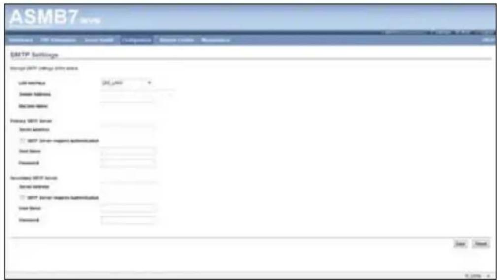
4.4.12 SMTP
The SMTP page allows you to configure SMTP mail server. Enter the IP address of the mail server, and then click Save to apply the settings.
4.4.13 SSL
The Secure Socket Layer protocol was created by Netscape to ensure secure transactions between web servers and browsers. The protocol uses a third party, a Certificate Authority (CA), to identify one end or both end of the transactions. To open SSL Certificate Configuration page, click Configuration > SSL from the main menu. There are three tabs in this page.
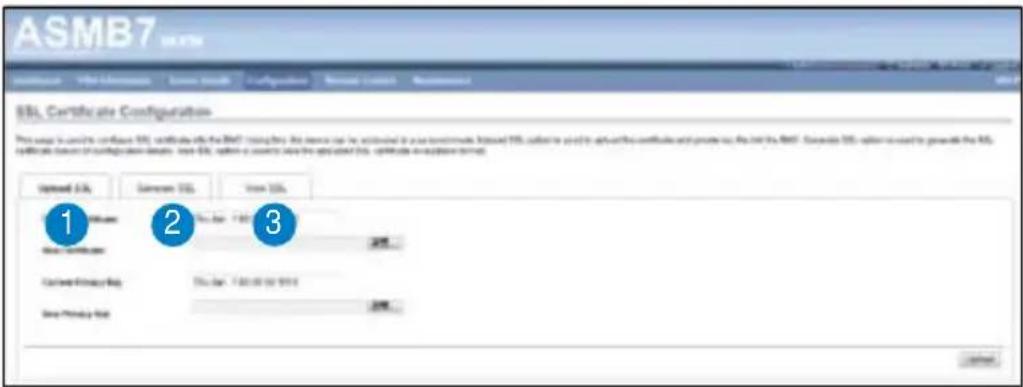
- Upload SSL option is used to upload the certificate and private key file into the BMC.
- Generate SSL option is used to generate the SSL certificate based on configuration details.
- View SSL option is used to view the uploaded SSL certificate in readable format.

The fields of SSL Certificate Configuration – Upload SSL tab are explained below.
- Current Certificate: Current certificate information will be displayed (read-only).
- New Certificate: Certificate file should be of pem type
- Current Privacy Key: Current privacy key information will be displayed (read-only).
- New Privacy Key: Privacy key file should be of pem type
- Upload: To upload the SSL certificate and privacy key into the BMC.

Upon successful upload, HTTPS service will get restarted to use the newly uploaded SSL certificate.

The fields of SSL Certificate Configuration – Generate SSL tab are explained below.
-
Common Name(CN): Common name for which certificate is to be generated.
-
Maximum length of 64 characters.
-
Special characters '#' and '\$' are not allowed.
-
Organization(O): Organization name for which the certificate is to be generated.
-
Maximum length of 64 characters.
-
Special characters '#' and '\$' are not allowed.
-
Organization Unit(OU): Over all organization section unit name for which certificate is to be generated.
-
Maximum length of 64 characters.
-
Special characters '#' and '\$' are not allowed.
-
City or Locality(L): City or Locality of the organization (mandatory).
-
Maximum length of 64 characters.
-
Special characters '#' and '\$' are not allowed.
-
State or Province(ST): State or Province of the organization (mandatory).
-
Maximum length of 64 characters.
-
Special characters '#' and '\$' are not allowed.
-
Country(C): Country code of the organization (mandatory).
-
Only two characters are allowed.
-
Special characters are not allowed.
-
Email Address: Email Address of the organization (mandatory).
-
Valid for: Validity of the certificate.
- Value ranges from 1 to 3650 days.
- Key Length: The key length bit value of the certificate.
- Generate: To generate the new SSL certificate.

HTTPS service will get restarted, to use the newly generated SSL certificate.

The fields of SSL Certificate Configuration – Generate SSL tab are explained below.
-
Basic Information: This section displays the basic information about the uploaded SSL certificate. It displays the following fields.
-
Version
- Serial Number
- Signature Algorithm
-
Public Key
-
Issued From: This section describes the following Certificate Issuer information
-
Common Name(CN)
- Organization(O)
- Organization Unit(OU)
- City or Locality(L)
• State or Province(ST) - Country(C)
-
Email Address
-
Validity Information: This section displays the validity period of the uploaded certificate.
-
Valid From
-
Valid To
-
Issued To: This section displays the information about the certificate issuer.
-
Common Name(CN)
-
Organization(O)
-
Organization Unit(OU)
- City or Locality(L)
• State or Province(ST) - Country(C)
- Email Address
Procedure
- Click the Upload SSL Tab, Browse the New Certificate and New Privacy key.
- Click Upload to upload the new certificate and privacy key.
- In Generate SSL tab, enter the following details in the respective fields
• The Common Name for which the certificate is to be generated.
• The Name of the Organization for which the certificate is to be generated. - The Overall Organization Section Unit name for which certificate to be generated.
• The City or Locality of the organization
• The State or Province of the organization
• The Country of the organization
• The email address of the organization. -
The number of days the certificate will be valid in the Valid For field.
-
Choose the Key Length bit value of the certificate
-
Click Generate to generate the certificate.
-
Click View SSL tab to view the uploaded SSL certificate in user readable format.

- Once you Upload/Generate the certificates, only HTTPS service will get restarted.
- You can now access your Generic MegaRAC® SP securely using the following format in your IP Address field from your Internet browser: https://
- For example, if your MegaRAC® SP's IP address is 192.168.0.30, enter the following: https://192.168.0.30
- Please note the
after. You must accept the certificate before you are able to access your Generic MegaRAC® SP.
4.4.14 Users
The User Management page allows you to view the current list of user slots for the server. You can add a new user and modify or delete the existing users.
To open User Management page, click Configuration >Users from the main menu. A sample screenshot of User Management Page is shown in the screenshot below.

- User ID: Displays the ID number of the user. Note: The list contains a maximum of ten users only.
- User Name: Displays the name of the user.
- User Access: To enable or disable the access privilege of the user.
- Network Privilege: Displays the network access privilege of the user.
- SNMP Status: Displays if the SNMP status for the user is enabled or Disabled.
- Email ID: Displays email address of the user. Add User: To add a new user.
- Add User: To add a new user.
- Modify User: To modify an existing user.
- Delete User: To delete an existing user.
Add a new user:
- To add a new user, select a free slot and click Add User.
- Enter the name of the user in the User Name field.
- In the Password and Confirm Password fields, enter and confirm your new password.
- Password must be at least 8 characters long. White space is not allowed. This field will not allow more than 20 characters.
5 Enable or Disable the User Access Privilege.
6. In the Network Privilege field, enter the network privilege assigned to the user which could be Administrator, Operator, User or No Access.
7. Check the SNMP Status check box to enable SNMP access for the user.
NOTE: Password field is mandatory, if SNMP Status is enabled.
8. Choose the SNMP Access level option for user from the SNMP Access dropdown list. Either it can be Read Only or Read Write.
9. Choose the Authentication Protocol to use for SNMP settings from the drop down list. NOTE: Password field is mandatory, if Authentication protocol is changed.
10. Choose the Encryption algorithm to use for SNMP settings from the Privacy protocol dropdown list.
11. In the Email ID field, enter the email ID of the user. If the user forgets the password, the new password will be mailed to the configured email address.
AMI-Format: The subject of this mail format is 'Alert from (your Hostname)'. The mail content shows sensor information, ex: Sensor type and Description.
Fixed-Subject Format: This format displays the message according to user's setting. You must set the subject and message for email alert.
12. In the New SSK Key field, click Browse and select the SSH key file. Note: SSH key file should be of pub type.
13. Click Add to save the new user and return to the users list.
14. Click Cancel to cancel the modification and return to the users list.
1. Select an existing user from the list and click Modify User. This opens the Add User screen as shown in the screenshot below.
2. Edit the required fields.
3. To change the password, enable the Change Password option.
4. After editing the changes, click Modify to return to the users list page.
Modify an existing User
Delete an existing User
To delete an existing user, select the user from the list and click Delete User.
4.5 Remote Control
This section allows you to perform remote operations on the server. Click each function key to start using its specific functions

4.5.1 Console Redirection
The remote console application, which is started using the WebGUI, allows you to control your server's operating system remotely, using the screen, mouse, and keyboard, and to redirect local CD/DVD, Floppy diskette and Hard disk/USB thumb drives as if they were connected directly to the server.

Browser Settings
For Launching the KVM, pop-up block should be disabled. For Internet explorer, enable the download file options from the settings.
Java Console:
This is an OS independent plug-in which can be used in Windows as well as Linux with the help of JRE. JRE should be installed in the client's system. You can install JRE from the following link. http://www.java.com/en/download/manual.jsp
The Java Console can be launched in two ways
- Open the Dashboard Page and in Remote control section, click Launch for Java Console.
- Open Remote Control>Console Redirection Page and click Java Console.
This will download the .jnlp file from BMC.
To open the .jnlp file, use the appropriate JRE version (Javaws) When the downloading is done, it opens the Console Redirection window.
The Console Redirection main menu consists of the following menu items.
- Video
- Keyboard
- Mouse
- Options
- Media
- Keyboard Layout
- Help
A detailed explanation of these menu items are given below.

Video
This menu contains the following sub menu items.
- Pause redirection: This option is used for pausing Console Redirection.
- Resume Redirection: This option is used to resume the Console Redirection when the session is paused.
- Refresh Video: This option can be used to update the display shown in the Console Redirection window.
- Turn Off Host display: If you enable this option, the server display will be blank but you can view the screen in Console Redirection. If you disable this option, the display will be back in the server screen.
- Full Screen: This option is used to view the Console Redirection in full screen mode (Maximize). This menu is enabled only when both the client and host resolution are same.
- Exit: This option is used to exit the console redirection screen

Keyboard
This menu contains the following sub menu items.
- Hold Right Ctrl Key: This menu item can be used to act as the right-side
key when in Console Redirection. - Hold Right Alt Key: This menu item can be used to act as the right-side
key when in Console Redirection. - Hold Left Ctrl Key: This menu item can be used to act as the left-side
key when in Console Redirection. - Hold Left Alt Key: This menu item can be used to act as the left-side
key when in Console Redirection. - Left Windows Key: This menu item can be used to act as the left-side
key when in Console Redirection. You can also decide how the key should be pressed: Hold Down or Press and Release. - Right Windows Key: This menu item can be used to act as the right-side
key when in Console Redirection. You can also decide how the key should be pressed: Hold Down or Press and Release. - Alt+Ctrl+Del: This menu item can be used to act as if you depressed the
, and keys down simultaneously on the server that you are redirecting. - Context menu: This menu item can be used to act as the context menu key, when in Console Redirection.

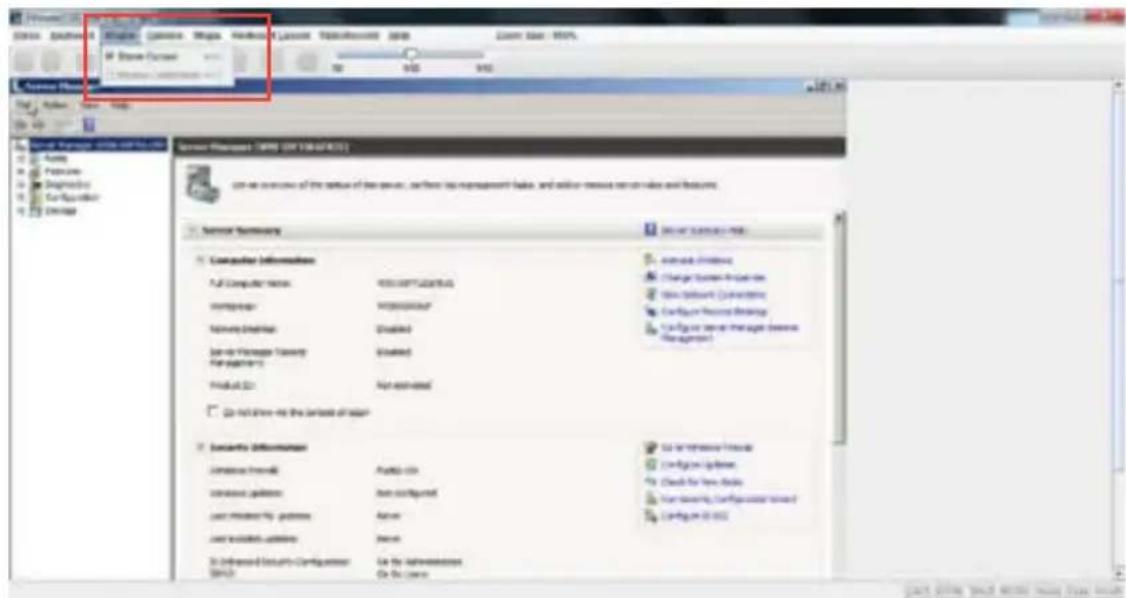
Mouse
- Show Cursor: This menu item can be used to show or hide the local mouse cursor on the remote client system.
- Mouse Calibration: This menu item can be used only if the mouse mode is relative.
In this step, the mouse threshold settings on the remote server will be discovered. The local mouse cursor is displayed in RED color and the remote cursor is part of the remote video screen. Both the cursors will be synchronized in the beginning. Please use '+' or '-' keys to change the threshold settings until both the cursors go out of synch. Please detect the first reading on which cursors go out of synch. Once this is detected, use 'ALT-T' to save the threshold value.
Options
Band width: The Bandwidth Usage option allows you to adjust the bandwidth. You can select one of the following:
- Auto Detect: This option is used to detect client system keyboard layout automatically and send the key event to the host based on the Layout detected.
- 256 Kbps
- 512 Kbps
- 1 Mbps
- 10 Mbps
Keyboard/Mouse Encryption: This option allows you to encrypt keyboard inputs and mouse movements sent between the connections.
Zoom:
This option is available only when you launch the Java Console.
- Zoom In: For increasing the screen size. This zoom varies from 100% to 150% with an interval of 10%
- Zoom Out: For decreasing the screen size. This zoom varies from 100% to 50% with an interval of 10%

Media
Virtual Media Wizard:
To add or modify a media, select and click 'Virtual Media Wizard' button, which pops out a box named "Virtual Media" where you can configure the media. A sample screenshot of Virtual media screen is given below. Virtual Media.
Floppy Key Media: This menu item can be used to start or stop the redirection of a physical floppy drive and floppy image types such as img.
CD/DVD Media: This menu item can be used to start or stop the redirection of a physical DVD/CD-ROM drive and cd image types such as iso.
Hard disc/USB Key Media: This menu item can be used to start or stop the redirection of a Hard Disk/USB key image and USB key image such as img.


Virtual Media Wizard
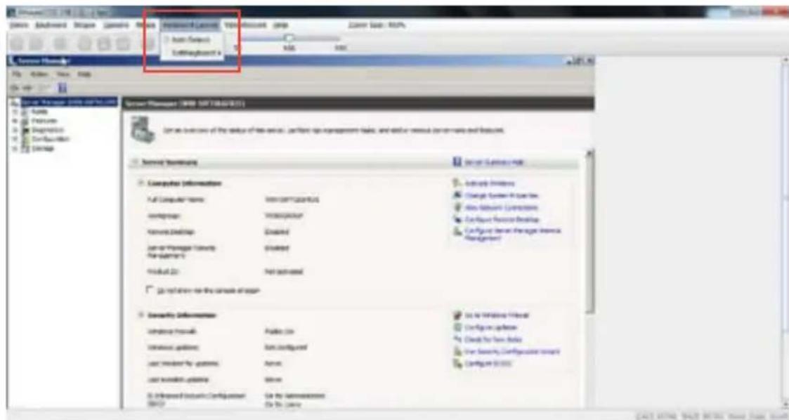
Keyboard Layout
Auto Detect: This option is used to detect keyboard layout automatically. The languages supported automatically are English – US, French – France, Spanish – Spain, German- Germany, Japanese- Japan. If the client and host languages are same, then for all the languages other than English mentioned above, you must select this option to avoid typo errors.
Soft Keyboard: This option allows you to select the keyboard layout. It will show the dialog as similar to onscreen keyboard. If the client and host languages are different, then for all the languages other than English mentioned above, you must select the appropriate language in the list shown in JViewer and use the softkeyboard to avoid typo errors. Note: Soft keyboard is applicable only for JViewer Application not for other application in the client system. Soft keyboard is applicable only for JViewer Application not for other application in the client system
4.5.2 Server Power Control
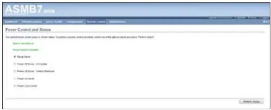
The Server Power Control page displays the current server power status and allows you to change the current settings. Select the desired option, and then click Perform Action to execute the selected action.
4.5.3 Chassis Identify Command
The Chassis Identify Command page allows you to perform a chassis identify command control operation. Enter identify interval in seconds, and then click Perform Action to start the command.

4.5.4 Power Button
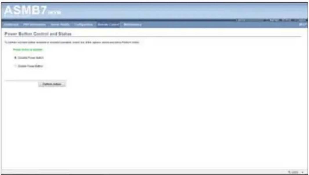
The Power Button page allows you to enable or disable power button and click Perform Action to confirm the selection.
4.6 Maintenance
This section allows you to perform the firmware update for the remote server. You can also use Restore Factory Defaults to reset system settings.
4.6.1 Firmware Update
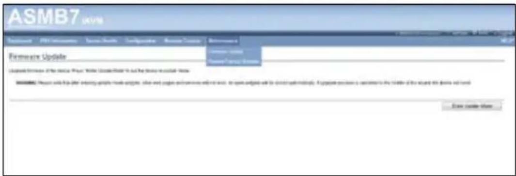
This section allows you to enter the update mode, and update the firmware of ASMB7. Please note that after entering update mode widgets, other web pages and services will not work. All open widgets will be closed automatically. If upgrade process is cancelled in the middle of the wizard, the device will reset.

4.6.2 Restore Factory Default
This section allows you to restore all settings to factory default. Please click the Restore Factory to reset all settings.
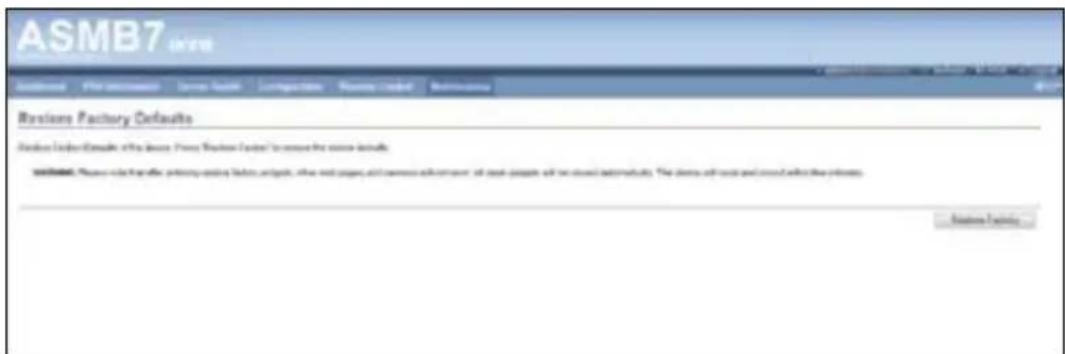
The Appendix shows the location of the LAN ports for server management and BMC connector on server motherboards. This section also presents common problems that you may encounter when installing or using the server management board.
Reference information
A.1 BMC connector
The ASUS server motherboards that support the ASMB7-iKVM comes with a Baseboard Management Controller (BMC) connector.
Refer to the illustration below to locate the BMC connector on different server motherboards.


The motherboard illustration is for reference only. The motherboard layout and appearance may vary depending on the model..
A.2 LAN ports for server management
The ASUS server motherboards that support the ASMB7-iKVM comes with three LAN (RJ-45) ports: one for network connection and the other two for server management. For easy identification, the LAN ports for server management are LAN1 and DM_LAN1 ports. You must use the LAN1 and DM_LAN1 ports for server management to connect the remote server to the local/central host (direct LAN connection) or to the network hub or router.
Refer to the illustration below to identify the LAN1 and DM_LAN1 ports for server management on some server motherboards.


You may refer to motherboard manual for the location of LAN1 and DM_LAN1 ports.
A.3 Troubleshooting

This troubleshooting guide provides answers to some common problems that you may encounter while installing and/or using ASUS ASMB7-iKVM. These problems require simple troubleshooting that you can perform by yourself. Contact the Technical Support if you encounter problems not mentioned in this section.
| Problem Solution | |
| The local/central server cannot connect to the ASMB7-iKVM board | 1. Check if the LAN cable is connected to the LAN port.2. Make sure that the IP address of both the remote and local/central servers are on the same subnet.(Refer to chapter 2 for details.) Try “ping xx.xx.xx.xx” (remote server ip) on local/central server and make sure remote server could reply the ping request.3. Check if the IP source is set to [DHCP]. When set to [DHCP], you'll not be able to configure the IP address. |
| All the SEL (System Event Log) cannot be displayed | The maximum SEL number is 900 events. |
| The date/time shown in SEL (System Event Log) screen is incorrect | Refer to section 4.4.9 to check if the time zone is set up correctly. |
| ASMB7-iKVM has network connection problems in Firewall environment | Ask MIS to add the following port numbers in Firewall:5123 (virtual floppy) (TCP)5120 (virtual CDROM) (TCP)623 (IPMI) (TCP & UDP)80 (HTTP) (TCP)7578 (iKVM) (TCP)443 (HTTPS) (TCP)161 (SNMP) (UDP) |
| The Java redirection screen cannot be displayed normally | Click Refresh Page button to refresh the redirection screen. |

The ASMB JAVA console only works with the onboard VGA. Other add-on video cards may not properly display the ASMB JAVA console.
A.4 Sensor Table
Memory ECC
| Sensor No. | Sensor Name | Sensor Type | Sensor Type | code | Sensor Value or Event Type | Event Data 3 |
| 0xD1 | CPU1_ECC1 | Memory ECC Sensor | 0x0C | Discrete(0x6F)0x01: Correctable ECC0x02: Uncorrectable ECC0x40: Presence detected | 0x00: DIMM_A1, 0x01: DIMM_A2,0x02: DIMM_A3, 0x03:DIMM_A4,0x04: DIMM_B1, 0x05: DIMM_B2,0x06: DIMM_B3, 0x07: DIMM_B4,0x08: DIMM_C1, 0x09: DIMM_C2,0x0A: DIMM_C3, 0x0B: DIMM_C4,0x0C: DIMM_D1, 0x0D: DIMM_D2,0x0E: DIMM_D3, 0x0F: DIMM_D4 | |
| 0xD2 | CPU1_ECC2 | OEM Memory ECC Sensor(For Intel DP platform only-- ASUS Z8 series serverMB; -E6 server system) | 0xC1 | Discrete(0x6F)0x01: Read ECC error0x02: ECC Error occurred on a scrub0x04: Write Parity Error0x08: Error in Redundant memory0x10: Sparing Error0x20: Memory access out of Range0x40: Address Parity Error0x80: Byte Enable Parity | 0x00: DIMM_A1, 0x01: DIMM_A2,0x02: DIMM_A3, 0x03:DIMM_A4,0x04: DIMM_B1, 0x05: DIMM_B2,0x06: DIMM_B3, 0x07: DIMM_B4,0x08: DIMM_C1, 0x08: DIMM_C2,0x0A: DIMM_C3, 0x0B: DIMM_C4,0x0C: DIMM_D1, 0x0D: DIMM_D2,0x0E: DIMM_D3, 0x0F: DIMM_D4 | |
| 0xD3 | CPU2_ECC1 | Memory ECC Sensor | 0x0C | Discrete(0x6F)0x01: Correctable ECC0x02: Uncorrectable ECC0x40: Presence detected | 0x00: DIMM_D1, 0x01: DIMM_D2,0x02: DIMM_D3, 0x03: DIMM_D4,0x04: DIMM_E1, 0x05: DIMM_E2,0x06: DIMM_E3, 0x07: DIMM_E4,0x08: DIMM_F1, 0x09: DIMM_F2,0x0A: DIMM_F3, 0x0B: DIMM_F4,0x0C: DIMM_G1, 0x0D: DIMM_G2,0x0E: DIMM_G3, 0x0F: DIMM_G4,0x10: DIMM_H1, 0x11: DIMM_H2,0x12: DIMM_H3, 0x13: DIMM_H4,0x14: DIMM_C1, 0x15: DIMM_C2,0x16: DIMM_C3, 0x17: DIMM_C4 | |
| 0xD4 CPU2_ECC2 OEM Mem | Memory ECC Sensor(For Intel DP platform only-- ASUS Z8 series serverMB; -E6 server system) | 0xC1 Discrete | (0x6F)0x01: Read ECC error0x02: ECC Error occurred on a scrub0x04: Write Parity Error0x08: Error in Redundant memory0x10: Sparing Error0x20: Memory access out of Range0x40: Address Parity Error0x80: Byte Enable Parity | 0x00: DIMM_D1, 0x01: DIMM_D2,0x02: DIMM_D3, 0x03: DIMM_D4,0x04: DIMM_E1, 0x05: DIMM_E2,0x06: DIMM_E3, 0x07: DIMM_E4,0x08: DIMM_F1, 0x08: DIMM_F2,0x0A: DIMM_F3, 0x0B: DIMM_F4,0x0C: DIMM_G1, 0x0D: DIMM_G2,0x0E: DIMM_G3, 0x0F: DIMM_G4,0x10: DIMM_H1, 0x11: DIMM_H2,0x12: DIMM_H3. 0x13: DIMM_H4,0x14: DIMM_C1, 0x15: DIMM_C2,0x16: DIMM_C3, 0x17: DIMM_C4 | ||
Backplane HD
Sensor No. Sensor Name Sensor Type Sensor Type Code Sensor Value or Event Type
| 0x68 | Backplane1 HD1 | Drive Slot | 0x0D | Discrete(0x6F)0x01: Drive Presence0x02: Drive Fault0x80: Rebuild |
| 0x69 | Backplane1 HD2 | Drive Slot | 0x0D | Discrete(0x6F)0x01: Drive Presence0x02: Drive Fault0x80: Rebuild |
| 0x6A | Backplane1 HD3 | Drive Slot | 0x0D | Discrete(0x6F)0x01: Drive Presence0x02: Drive Fault0x80: Rebuild |
| 0x6B | Backplane1 HD4 | Drive Slot | 0x0D | Discrete(0x6F)0x01: Drive Presence0x02: Drive Fault0x80: Rebuild |
| 0x6C | Backplane1 HD5 | Drive Slot | 0x0D | Discrete(0x6F)0x01: Drive Presence0x02: Drive Fault0x80: Rebuild |
| 0x6D | Backplane1 HD6 | Drive Slot | 0x0D | Discrete(0x6F)0x01: Drive Presence0x02: Drive Fault0x80: Rebuild |
| 0x6E | Backplane1 HD7 | Drive Slot | 0x0D | Discrete(0x6F)0x01: Drive Presence0x02: Drive Fault0x80: Rebuild |
| 0x6F | Backplane1 HD8 | Drive Slot | 0x0D | Discrete(0x6F)0x01: Drive Presence0x02: Drive Fault0x80: Rebuild |
| 0x78 | Backplane2 HD1 | Drive Slot | 0x0D | Discrete(0x6F)0x01: Drive Presence0x02: Drive Fault0x80: Rebuild |
| 0x79 | Backplane2 HD2 | Drive Slot | 0x0D | Discrete(0x6F)0x01: Drive Presence0x02: Drive Fault0x80: Rebuild |
| 0x7A | Backplane2 HD3 | Drive Slot | 0x0D | Discrete(0x6F)0x01: Drive Presence0x02: Drive Fault0x80: Rebuild |
| 0x7B | Backplane2 HD4 | Drive Slot | 0x0D | Discrete(0x6F)0x01: Drive Presence0x02: Drive Fault0x80: Rebuild |
| 0x7C | Backplane2 HD5 | Drive Slot | 0x0D | Discrete(0x6F)0x01: Drive Presence0x02: Drive Fault0x80: Rebuild |
| 0x7D | Backplane2 HD6 | Drive Slot | 0x0D | Discrete(0x6F)0x01: Drive Presence0x02: Drive Fault0x80: Rebuild |
| 0x7E | Backplane2 HD7 | Drive Slot | 0x0D | Discrete(0x6F)0x01: Drive Presence0x02: Drive Fault0x80: Rebuild |
| 0x7F | Backplane2 HD8 | Drive Slot | 0x0D | Discrete(0x6F)0x01: Drive Presence0x02: Drive Fault0x80: Rebuild |
Power Supply
Sensor No. Sensor Name Sensor Type Sensor Type Code Sensor Value or Event Type
| 0x81 | PSU1 Temp | Temperature | 0x01 | Threshold(0x01)Upper Non-Critical - going highUpper Critical - going high |
| 0x82 | PSU1 Fan1 | FAN | 0x04 | Threshold(0x01)Lower Non-critical - going lowLower Critical - going low |
| 0x83 | PSU1 Fan2 | FAN | 0x04 | Threshold(0x01)Lower Non-critical - going lowLower Critical - going low |
| 0x92 | PSU1 Over Temp | Temperature | 0x01 | Discrete(0x07)0x01: Transition to OK0x10: Transition to Non-Critical from more severe0x40: Transition to Non-Recoverable |
| 0x93 | PSU1 FAN Low | FAN | 0x04 | Discrete(0x07)0x01: Transition to OK0x10: Transition to Non-Critical from more severe |
| 0x94 | PSU1 AC | Power Supply | 0x08 | Discrete(0x6F)0x01: Presence Detected0x08: Power Supply input lost (AC/DC) |
| 0x95 | PSU1 Slow FAN1 | FAN | 0x04 | Discrete(0x07)0x01: Transition to OK0x10: Transition to Non-Critical from more severe0x40: Transition to Non-Recoverable |
| 0x96 | PSU1 Slow FAN2 | FAN | 0x04 | Discrete(0x07)0x01: Transition to OK0x10: Transition to Non-Critical from more severe0x40: Transition to Non-Recoverable |
| 0x97 | PSU1 PWR Detect | Power Supply | 0x08 | Discrete(0x6F)0x01: Presence Detected0x02: Power Supply Failure Detected |
| 0x84 | PSU2 Temp | Temperature | 0x01 | Threshold(0x01)Upper Non-Critical - going highUpper Critical - going high |
| 0x85 | PSU2 Fan1 | FAN | 0x04 | Threshold(0x01)Lower Non-critical - going lowLower Critical - going low |
| 0x86 | PSU2 Fan2 | FAN | 0x04 | Threshold(0x01)Lower Non-critical - going lowLower Critical - going low |
| 0x9A | PSU2 Over Temp | Temperature | 0x01 | Discrete(0x07)0x01: Transition to OK0x10: Transition to Non-Critical from more severe0x40: Transition to Non-Recoverable |
| 0x9B | PSU2 FAN Low | FAN | 0x04 | Discrete(0x07)0x01: Transition to OK0x10: Transition to Non-Critical from more severe |
| 0x9C | PSU2 AC Lost | Power Supply | 0x08 | Discrete(0x6F)0x01: Presence Detected0x08: Power Supply input lost (AC/DC) |
| 0x9D | PSU2 Slow FAN1 | FAN | 0x04 | Discrete(0x07)0x01: Transition to OK0x10: Transition to Non-Critical from more severe0x40: Transition to Non-Recoverable |
| 0x9E | PSU2 Slow FAN2 | FAN | 0x04 | Discrete(0x07)0x01: Transition to OK0x10: Transition to Non-Critical from more severe0x40: Transition to Non-Recoverable |
| 0x9F | PSU2 PWR Detect | Power Supply | 0x08 | Discrete(0x6F)0x01: Presence Detected0x02: Power Supply Failure Detected |
Hardware Monitor
| Sensor No. Sensor Name Sensor Type Sensor Type Code Sensor Value or Event Type | ||||
| 0x31 | CPU1 Temperature | Temperature | 0x01 | Threshold(0x01)Upper Non-critical - going highUpper Critical - going high |
| 0x32 | CPU2 Temperature | Temperature | 0x01 | Threshold(0x01)Upper Non-critical - going highUpper Critical - going high |
| 0xCC | TR1 Temperature | Temperature | 0x01 | Threshold(0x01)Upper Non-critical - going highUpper Critical - going high |
| 0xCD | TR2 Temperature | Temperature | 0x01 | Threshold(0x01)Upper Non-critical - going highUpper Critical - going high |
| 0x34 | VCORE1 | Voltage | 0x02 | Threshold(0x01)Lower Non-critical - going lowLower Critical - going lowUpper Non-critical - going highUpper Critical - going high |
| 0x35 | VCORE2 | Voltage | 0x02 | Threshold(0x01)Lower Non-critical - going lowLower Critical - going lowUpper Non-critical - going highUpper Critical - going high |
| 0x36 | +3.3V | Voltage | 0x02 | Threshold(0x01)Lower Non-critical - going lowLower Critical - going lowUpper Non-critical - going highUpper Critical - going high |
| 0x37 | +5V | Voltage | 0x02 | Threshold(0x01)Lower Non-critical - going lowLower Critical - going lowUpper Non-critical - going highUpper Critical - going high |
| 0x38 | +12V | Voltage | 0x02 | Threshold(0x01)Lower Non-critical - going lowLower Critical - going lowUpper Non-critical - going highUpper Critical - going high |
| 0x39 | +1.5V ICH(For Intel DP platform only -- ASUS Z8 series server MB; -E6 server system) | Voltage | 0x02 | Threshold(0x01)Lower Non-critical - going lowLower Critical - going lowUpper Non-critical - going highUpper Critical - going high |
| 0x3A | +1.1V IOH(For Intel DP platform only -- ASUS Z8 series server MB; -E6 server system) | Voltage | 0x02 | Threshold(0x01)Lower Non-critical - going lowLower Critical - going lowUpper Non-critical - going highUpper Critical - going high |
| 0x3B | +5VSB | Voltage | 0x02 | Threshold(0x01)Lower Non-critical - going lowLower Critical - going lowUpper Non-critical - going highUpper Critical - going high |
| 0x3C | VBAT | Voltage | 0x02 | Threshold(0x01)Lower Non-critical - going lowLower Critical - going lowUpper Non-critical - going highUpper Critical - going high |
| 0x3D | P1VTT(For Intel DP platform only -- ASUS Z8 series server MB; -E6 server system) | Voltage | 0x02 | Threshold(0x01)Lower Non-critical - going lowLower Critical - going lowUpper Non-critical - going highUpper Critical - going high |
| 0x3E | +1.5V P1DDR3(For Intel platform only -- ASUS Z8 series server MB; -E6 server system) | Voltage | 0x02 | Threshold(0x01)Lower Non-critical - going lowLower Critical - going lowUpper Non-critical - going highUpper Critical - going high |
| 0x3F | P2VTT(For Intel DP platform only -- ASUS Z8 series server MB; -E6 server system) | Voltage | 0x02 | Threshold(0x01)Lower Non-critical - going lowLower Critical - going lowUpper Non-critical - going highUpper Critical - going high |
| 0x40 | +3.3VSB | Voltage | 0x02 | Threshold(0x01)Lower Non-critical - going lowLower Critical - going lowUpper Non-critical - going highUpper Critical - going high |
| 0x41 | +1.5V_P2DDR3(For Intel DP platform only -- ASUS Z8 series server MB; -E6 server system) | Voltage | 0x02 | Threshold(0x01)Lower Non-critical - going lowLower Critical - going lowUpper Non-critical - going highUpper Critical - going high |
| 0x42 | P1DDR3(For AMD platform only) | Voltage | 0x02 | Threshold(0x01)Lower Non-critical - going lowLower Critical - going lowUpper Non-critical - going highUpper Critical - going high |
| 0x42 | +1.5V(For Intel UP platform only) | Voltage | 0x02 | Threshold(0x01)Lower Non-critical - going lowLower Critical - going lowUpper Non-critical - going highUpper Critical - going high |
| 0x43 | P2DDR3(For AMD platform only) | Voltage | 0x02 | Threshold(0x01)Lower Non-critical - going lowLower Critical - going lowUpper Non-critical - going highUpper Critical - going high |
| 0x44 | P1_+1.2V(For AMD platform only) | Voltage | 0x02 | Threshold(0x01)Lower Non-critical - going lowLower Critical - going lowUpper Non-critical - going highUpper Critical - going high |
| 0x45 | P2_+1.2V(For AMD platform only) | Voltage | 0x02 | Threshold(0x01)Lower Non-critical - going lowLower Critical - going lowUpper Non-critical - going highUpper Critical - going high |
| 0x46 | P1_VDDNB(For AMD platform only) | Voltage | 0x02 | Threshold(0x01)Lower Non-critical - going lowLower Critical - going lowUpper Non-critical - going highUpper Critical - going high |
| 0x47 | +1.8V(For AMD platform only) | Voltage | 0x02 | Threshold(0x01)Lower Non-critical - going lowLower Critical - going lowUpper Non-critical - going highUpper Critical - going high |
| 0x48 | +1.2V(For AMD platform only) | Voltage | 0x02 | Threshold(0x01)Lower Non-critical - going lowLower Critical - going lowUpper Non-critical - going highUpper Critical - going high |
| 0x49 | +1.1V(For AMD platform only) | Voltage | 0x02 | Threshold(0x01)Lower Non-critical - going lowLower Critical - going lowUpper Non-critical - going highUpper Critical - going high |
| 0x4A | VTT(For AMD platform only) | Voltage | 0x02 | Threshold(0x01)Lower Non-critical - going lowLower Critical - going lowUpper Non-critical - going highUpper Critical - going high |
| 0xA0 | CPU_FAN1 | FAN | 0x04 | Threshold(0x01)Lower Non-critical - going lowLower Critical - going low |
| 0xA1 | CPU_FAN2 | FAN | 0x04 | Threshold(0x01)Lower Non-critical - going lowLower Critical - going low |
| 0xA2 | FRNT_FAN1 | FAN | 0x04 | Threshold(0x01)Lower Non-critical - going lowLower Critital - going low |
| 0xA3 | FRNT_FAN2 | FAN | 0x04 | Threshold(0x01)Lower Non-critical - going lowLower Critital - going low |
| 0xA4 | FRNT_FAN3 | FAN | 0x04 | Threshold(0x01)Lower Non-critical - going lowLower Critital - going low |
| 0xA5 | FRNT_FAN4 | FAN | 0x04 | Threshold(0x01)Lower Non-critical - going lowLower Critital - going low |
| 0xA6 | REAR_FAN1 | FAN | 0x04 | Threshold(0x01)Lower Non-critical - going lowLower Critital - going low |
| 0xA7 | REAR_FAN2 | FAN | 0x04 | Threshold(0x01)Lower Non-critical - going lowLower Critital - going low |
| 0xA8 | FRNT_FAN5 | FAN | 0x04 | Threshold(0x01)Lower Non-critical - going lowLower Critital - going low |
| 0xA9 | FRNT_FAN6 | FAN | 0x04 | Threshold(0x01)Lower Non-critical - going lowLower Critital - going low |
| 0xAA | FRNT_FAN7 | FAN | 0x04 | Threshold(0x01)Lower Non-critical - going lowLower Critital - going low |
| 0x4F | Chassis Intrusion | Physical Security (Chassis Intrusion) | 0x05 | Discrete(0x6F)0x01: General Chassis Intrusion0x02: Drive Bay Intrusion |
ASUS contact information
ASUSTeK COMPUTER INC.
Address 15 Li-Te Road, Peitou, Taipei, Taiwan 11259
Telephone +886-2-2894-3447
Fax +886-2-2890-7798
E-mail info@asus.com.tw
Address 15 Li-Te Road, Peitou, Taipei, Taiwan 11259
Telephone +886-2-2894-3447
Fax +886-2-2890-7798
E-mail info@asus.com.tw
Address No.508, Chundong Road, Xinzhuang Industrial Zone, Minhang District, Shanghai, China.
Telephone +86-21-5442-1616
Fax +86-21-5442-0099
Web site http://www.asus.com.cn
Technical Support
Telephone +86-21-3407-4610 (800-820-6655)
Online Support http://support.asus.com/techserv/techserv.aspx
ASUS contact information
ASUS COMPUTER INTERNATIONAL (America)
Address 800 Corporate Way, Fremont, CA 94539, USA
Fax +1-510-608-4555
Web site http://usa.asus.com
Technical Support
Support fax +1-812-284-0883
General support +1-812-282-2787
Online support http://support.asus.com/techserv/techserv.aspx
ASUS COMPUTER GmbH (Germany and Austria)
Address Harkort Str. 21-23, D-40880 Ratingen, Germany
Fax +49-2102-959911
Web site http://www.asus.de
ASUS Czech Service s.r.o. (Europe)
Address Na Rovince 887, 720 00 Ostrava – Hrabová, Czech
Republic
Telephone +420-596766888
Web site http://www.asus.cz
Technical Support
Telephone +420-596-766-891
Fax +420-596-766-329
E-mail advance.rma.eu@asus.com
Online Support http://support.asus.com/techserv/techserv.aspx
ASUS contact information
ASUS Holland BV (The Netherlands)
Address Marconistraat 2, 7825GD EMMEN, The Netherlands
Web site http://www.asus.com
Technical Support
Telephone +31-(0)591-5-70292
Fax +31-(0)591-666853
E-mail advance.rma.eu@asus.com
Online Support http://support.asus.com/techserv/techserv.aspx
ASUS Polska Sp. z o.o. (Poland)
Address UI. Post□pu 6, 02-676 Warszawa, Poland
Web site http://pl.asus.com
Technical Support
Telephone +48-225718033
Online Support http://support.asus.com/techserv/techserv.aspx
ASK-Service (Russia and CIS)
Address □.□□□□□, □□. □□□□□□□□□□, □.10, □□□□□
Telephone (495) 640-32-75
EC Declaration of Conformity
We, the undersigned,
| Manufacturer: | ASUSTeK COMPUTER INC. |
| Address, City: | 4F, No. 100, LI-TE Rd., PEITOU, TAIPEI 112, TAIWAN |
| Country: | TAIWAN |
| Authorized representative in Europe: | ASUS COMPUTER GmbH |
| Address, City: | HARKORT STR. 21-23. 40880 RATINGEN |
| Country: | GERMANY |
| Product name : Management Card | |
| Model name : ASMB7-IKVM |
conform with the essential requirements of the following directives:
2004/108/EC-EMC Directive
| EN 55022:2010 | EN 55024:2010 |
| EN 61000-3-2:2006+A2:2009 | EN 61000-3-3:2008 |
| EN 55013:2001+A1:2003+A2:2006 | EN 55020:2007+A11:2011 |
| 1999/5/EC-R &TTE Directive | |
| EN 300 3/8 V1.7.1(2006-10) | EN 301 489-1 V1.9.2(2011-09) |
| EN 300 440-1 V1.6.1(2010-08) | EN 301 489-3 V1.4.1(2002-08) |
| EN 300 440.2 V1.4 (2010-08) | EN 301 489.4 V1.4 (2009-05) |
| EN 301 511 V9.0.2 (2003-03) | EN 301 489.7 V1.3 (2005-11) |
| EN 301 908-1 V5.2.1 (2011-05) | EN 301 489-9 V1.4.1 (2007-11) |
| EN 301 908-2 V5.2.1 (2011-07) | EN 301 489-17 V2.1.1 (2009-05) |
| EN 301 893 V1.6.1 (2011-11) | EN 301 489.24 V1.5.1 (2010-09) |
| EN 302 544-2 V1.1.1 (2009-01) | EN 302 326-2 V1.2.2 (2007-06) |
| EN 302 623 V1.1.1 (2009-01) | EN 302 326-3 V1.3.1 (2007-09) |
| EN 50360.2001 | EN 301 357-2 V1.4.1 (2006-11) |
| EN 50386:2002EN 62311:2008 | EN 302 201-2 V1.1.(2005-07) |
| □2006/95/EC-LVD Directive | |
| EN 60950-1 / A12:2011 | EN 60065:2002 / A12:2011 |
| ☐ 2009/125/EC-ErP Directive | |
| ☐ Regulation (EC) No. 1275/2008 | ☐ Regulation (EC) No. 278/2009 |
| ☐ Regulation (EC) No. 642/2009 | |
Var. 130208

(EC conformity marking)
Position: CEO
Name: Jerry Shen

Signature :
Declaration Date: 12/04/2013 Year to begin affixing CE marking:2013
Signature :
Apr. 12, 2013

This device complices with part 15 of the FCC Rules. Operation is subject to the following two conditions: (1) This device may not cause harmful interference, and (2) this device must accept any interference received, including interference that may cause undesired operation.
Supplementary Information:
☒ FCC Part 15, Subpart B, Unintentional Radiators
Model Number : ASMB7-IKVM
Conforms to the following specifications:
Product Name : Management Card
hereby declares that the product
Phone/Fax No: (510)739-3777/(510)608-4555
, CA 94539.
Address: 800 Corporate Way, Fremont
Responsible Party Name: Asus Computer International

DECLARATION OF CONFORMITY


- Server Management Board
- Copyright © 2013 ASUSTeK COMPUTER INC. All Rights Reserved.
- Contents
- Chapter 1: Product introduction
- Chapter 2: Installation
- Chapter 3: ASUS Host Management Controller Set-up
- Chapter 4: Web-based user interface
- Web-based user interface 4-2
- FRU Information 4-4
- Server Health 4-4
- Configuration....4-6
- Remote Control 4-30
- Maintenance 4-40
- Appendix: Reference information
- Notices
- Federal Communications Commission Statement
- Canadian Department of Communications Statement
- REACH
- ASUS Recycling/Takeback Services
- Safety information
- Electrical safety
- Operation safety
- About this guide
- How this guide is organized
- • Chapter 1: Product introduction
- • Chapter 2: Installation
- • Chapter 3: ASUS Host Management Controller Set-up
- • Chapter 4: Web-based user interface (ASMB7-iKVM only)
- - Appendix: Reference Information
- Where to find more information
- ASUS websites
- Optional documentation
- Conventions used in this guide
- Typography
- ASMB7-iKVM specifications summary
- Product introduction
- Welcome!
- Package contents
- Features
- IPMI 2.0
- Private I2C Bus
- PMBus\*
- PSMI\*
- Web-base GUI
- Update Firmware
- Notification
- KVM over Internet
- Remote Update BIOS
- Remote Storage (Virtual Media)
- Remote Install OS
- System requirements
- Network setup
- Installation
- Before you proceed
- Hardware installation
- Firmware update and IP configuration
- Configure BMC IP source static IP
- Configure BMC IP source DHCP
- BIOS configuration
- Running the BIOS BMC configuration
- BMC network configuration
- Configuration Source [Previous State]
- Station IP Address
- Subnet Mask
- Gateway IP Address
- System Event Log
- SEL Components [Disabled]
- Erase SEL [No]
- When SEL is Full [Do Nothing]
- IPv6 BMC Network Configuration
- IPv6 BMC DM\_LAN1 IP Address
- IPv6 BMC DM\_LAN1 IP Prefix Length
- IPv6 BMC DM\_LAN1 Default Gateway
- IPv6 BMC Lan1 IP Address Source [Previous State]
- IPv6 BMC Lan1 IP Address
- IPv6 BMC Lan1 IP Prefix Length
- IPv6 BMC Lan1 Default Gateway
- Running the ASMC7 utility
- Configuring the LAN controller
- Configuring the user name and password
- ASUS Host
- Management Controller Set-up
- ASUS Host Management Controller Setup
- Installing and launching the ASUS Host Management Controller Setup utility
- Command fields
- Initial
- View
- To view the System Event Log (SEL):
- To view the System Data Record (SDR):
- To view the BMC information:
- Set
- To select the host interface:
- To set the BMC Timer:
- Monitor
- To display a remote server information:
- Help
- Web-based user interface
- Web-based user interface
- Logging in the utility
- Using the utility
- FRU Information
- Server Health
- Sensor Readings (with Thresholds)
- Event Log
- Options - 12 Options
- Configuration
- Active Directory
- Procedure:
- To add a new Role Group
- To Modify Role Group
- To Delete a Role Group
- DNS
- LDAP
- Procedure
- Mouse Mode
- Network
- Network Bond
- NTP
- PEF
- Alert Policy Tab
- PEF Management LAN Destination Page
- RADIUS
- Remote Session
- Services
- SMTP
- SSL
- Users
- Add a new user:
- Modify an existing User
- Delete an existing User
- Remote Control
- Console Redirection
- Browser Settings
- Java Console:
- Video
- Keyboard
- Mouse
- Options
- Zoom:
- Media
- Virtual Media Wizard:
- Keyboard Layout
- Server Power Control
- Chassis Identify Command
- Power Button
- Maintenance
- Firmware Update
- Restore Factory Default
- Reference information
- A.1 BMC connector
- A.2 LAN ports for server management
- A.3 Troubleshooting
- A.4 Sensor Table
- Memory ECC
- Backplane HD
- Power Supply
- Hardware Monitor
- ASUS contact information
- ASUSTeK COMPUTER INC.
- ASUS COMPUTER INTERNATIONAL (America)
- ASUS COMPUTER GmbH (Germany and Austria)
- ASUS Czech Service s.r.o. (Europe)
- Technical Support
- ASUS Holland BV (The Netherlands)
- ASUS Polska Sp. z o.o. (Poland)
- ASK-Service (Russia and CIS)
Brand : ASUS
Model : ASMB7-IKVM
Category : Electronic board