
SRVFU01 - Light aircraft Beringer - Free user manual and instructions
Find the device manual for free SRVFU01 Beringer in PDF.


| Product Type | Audio Mixer / Interface |
| Brand | Beringer |
| Model | SRVFU01 |
| Dimensions (W x H x D) | 19.0 x 1.75 x 10.0 inches (rack-mount, 1U) |
| Weight | 10.5 lbs (4.8 kg) |
| Power Supply | AC 100-240V, 50/60Hz, 50W |
| Power Consumption | 50W max |
| Input Channels | 8 mono + 2 stereo |
| Output Channels | Main L/R, 2 aux sends, 1 headphone |
| Frequency Response | 20 Hz - 20 kHz (±1 dB) |
| Total Harmonic Distortion | <0.005% |
| Signal-to-Noise Ratio | 110 dB |
| EQ per Channel | 3-band (Low, Mid, High) with sweepable mid |
| Built-in Effects | 24-bit digital effects (reverb, delay, chorus) |
| Connectivity | XLR, 1/4" TRS, RCA, USB (for recording/playback) |
| USB Interface | 2x2 USB 2.0 audio interface |
| Phantom Power | +48V switchable per channel (select inputs) |
| Maintenance | Clean with dry, lint-free cloth. Avoid solvents. Keep vents clear. |
| Safety | Use grounded outlet. Do not expose to rain or moisture. Unplug when not in use. |
| Spare Parts Availability | Contact Beringer support for fuses, knobs, power supply. |
| Repairability | Serviceable by qualified technician. Do not disassemble. |
Frequently Asked Questions - SRVFU01 Beringer
User questions about SRVFU01 Beringer
0 question about this device. Answer the ones you know or ask your own.
Ask a new question about this device
Download the instructions for your Light aircraft in PDF format for free! Find your manual SRVFU01 - Beringer and take your electronic device back in hand. On this page are published all the documents necessary for the use of your device. SRVFU01 by Beringer.
USER MANUAL SRVFU01 Beringer
Installation and Maintenance Manual Van's RV3,4,6,6A,7,7A,8,8A,9,9A,10,12,14 and 14A
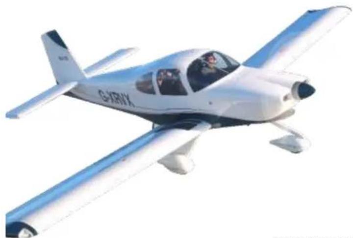
natural_image
White and blue small airplane in flight, no visible text or symbols on the aircraft bodyCopyright Jean Marie Urlacher
This documents contains 72 pages - Original in color
| E | ||||||
| D | ||||||
| C | ||||||
| B | ||||||
| A | 19/07/2017 | GAILLARD.C | BERINGER.G | SALLÉ.S | Edition initiale | TERMINÉ |
| Date | Name - Visa Redaction | Name – Visa Verification | Name – Visa Approbation | Modifications | Etat |
Installation and maintenance manual
Ref document:
BRG-MM-002(A)
| Van'sRV3,RV4,RV6,RV6A,RV7,RV7A,RV8,RV8A,RV9,RV9A,RV10,RV12,RV14 and RV14A | Page2 / 73 |
MODIFICATION LIST
| REV | Modifications |
| A | Edition initiale |
| B | |
| C | |
| D | |
| E |
Référence documents
| Title | Assembly reference | Rev |
| Van's RV14A,14 Main Wheel Assy | AV-VANS-220 | A |
| Van's RV3 Main Wheel Assy | AV-VANS-320 | A |
| Van's RV8 Main Wheel Assy | AV-VANS-420 | A |
| Van's RV10 Main Wheel Assy | AV-VANS-520 | A |
| Van's RV6,6A,7,7A,8A,9,9A Main Wheel Assy | AV-VANS-620 | A |
| Van's RV10,14A, Nose Wheel | AV-VANS-530 | A |
| Van's RV6A,7A,8A,9A Nose Wheel | AV-VANS-630 | A |
| Nature du document :Installation and Maintenance Manual | Ref document:BRG-MM-002(A) |
| Van'sRV3,RV4,RV6,RV6A,RV7,RV7A,RV8,RV8A,RV9,RV9A,RV10,RV12,RV14 and RV14A | Page3 / 73 |
SOMMAIRE
- GENERAL....5
- TIGHTENING TORQUE .... 5
- NOSE WHEEL KIT....6
3.1. RV6A,RV7A,RV8A AND RV9A 6
3.1.1. Nose wheel Assy (Drawing reference: AV-VANS-630)....6
3.2. RV10 AND RV14A....7
- FINISHING KIT FOR MAIN WHEELS......8
4.1. RV3 8
4.1.1. Main wheel Assy Right (Drawing reference: AV-VANS-320R) 8
4.1.2. Main wheel Assy Left (Drawing reference: AV-VANS-320L) 8
4.1.3. Hose Main wheel Assy Right and Left (Drawing reference: AV-VANS-410) 9
4.1.4. Installation Main wheel Assy Right and left (Drawing reference: AV-VANS-320R).... 10
4.2. RV4, RV6, RV6A, RV7, RV7A, RV8A, RV9 AND RV9A 13
4.2.1. Main wheel Assy Right (Drawing reference: AV-VANS-620R).... 13
4.2.2. Main wheel Assy Left (Drawing reference: AV-VANS-620L)....13
4.2.3. Hose Main wheel Assy Right and Left (Drawing reference: AV-VANS-610).... 14
4.2.4. Installation Main wheel Assy Right and left (Drawing reference: AV-VANS-620R).... 15
4.3. RV8 GROVE LANDING GEAR 18
4.3.1. Main wheel Assy Left (Drawing reference: AV-VANS-420L).... 18
4.3.2. Main wheel Assy Right (Drawing reference: AV-VANS-420R) 18
4.3.3. Hose Main wheel Assy Right and Left (Drawing reference: AV-VANS-410).... 19
4.3.4. Installation Main wheel Assy Right and left (Drawing reference: AV-VANS-420L) 20
4.4. RV10 23
4.4.1. Main wheel Assy Left (Drawing reference: AV-VANS-520L) 23
4.4.2. Main wheel Assy Right (Drawing reference: AV-VANS-520R) 23
4.4.3. Hose Main wheel Assy Right and Left (Drawing reference: AV-VANS-510) 24
4.4.4. Installation Main wheel Assy Right and left (Drawing reference: AV-VANS-520L) 25
4.5. RV14 28
4.5.1. Main wheel Assy Left (Drawing reference: AV-VANS-220L) 28
4.5.2. Main wheel Assy Right (Drawing reference: AV-VANS-220R) 28
4.5.3. Hose Main wheel Assy Right and Left (Drawing reference: AV-VANS-610) 29
4.5.4. Installation Main wheel Assy Left and right 30
- FUSELAGE KIT 32
Installation and Maintenance Manual
Ref document: BRG-MM-002(A)
 | Van'sRV3,RV4,RV6,RV6A,RV7,RV7A,RV8,RV8A,RV9,RV9A,RV10,RV12,RV14 and RV14A | Page4 / 73 |
5.1. FUSELAGE KIT VANS RV6,RV6A,RV7,RV7A,RV9,RV9A,RV10 AND RV14.... 32
5.1.1. Complete Hydraulic digram (Drawing reference AV-VANS-550) 33
5.1.2. Brake line....37
5.1.3. Assembly Master cylinder right and left (Drawing reference AV-VANS-560)....42
5.1.4. Assembly Brake reservoir (Drawing reference AV-VANS-570) 42
5.1.5. Assembly Parking brake valve(Drawing reference AV-VANS-580) 43
5.1.6. Assembly Parking brake valve(Drawing reference AV-VANS-590) 44
6. BRAKE LINE 45
7. MAINTENANCE 47
7.1. EQUIPMENT CONCERNED 47
7.2. QUICK REFERENCE SPECIFICATIONS 47
7.2.1. Tires: 47
7.2.2. Main Wheels: 48
7.2.3. Nose Wheels: 51
7.2.4. Brake caliper: 52
7.3. CLEANING 55
7.4. CONDITIONING PROCEDURE FOR BRAKE PADS 55
7.5. SCHEDULED MAINTENANCE CHECKS 56
7.5.1. 100h / Annual inspection .... 56
7.5.2. Safety maintenance checks.... 57
7.5.3. Replacement schedule of wear parts.... 59
7.5.4. Airworthiness Limitations....60
7.6. DISASSEMBLY - REASSEMBLY - TIRE CHANGE 61
7.6.1. Disassembly: 61
7.6.2. Reassembly: 63
7.7. MAINTENANCE OF WHEEL ASSEMBLY 65
7.7.1. Disassemble the wheel 65
7.7.2. Reassemble the wheel 67
7.8. BRAKE ASSEMBLY 69
7.8.1. Disassembly-Reassembly-Brake Pads change....69
8. TROUBLESHOOTING....72
Installation and Maintenance Manual
Ref document: BRG-MM-002(A)
| Van'sRV3,RV4,RV6,RV6A,RV7,RV7A,RV8,RV8A,RV9,RV9A,RV10,RV12,RV14 and RV14A | Page5 / 73 |
1. General
This manual gives the installation procedures of BERINGER wheel and brake system on the Van's RV3,4,6,6A,7,7A,8,8A,9,9A,10,12,14 and 14A.
CAUTION: Substitution of parts by other than originally certified parts may cause failure of brake system. BERINGER quality process assures that replacement parts are produced and controlled with the same quality level as originally certified.
BERINGER brake system functioning is similar to original brake system.
CAUTION: Standard MIL-H-5606 Brake fluid is replaced by fire resistant fluid: MIL-PRF-87257, make sure that only this brake fluid is used.
Note: after each part number the (-) indicates the minor revision status starting from letter A then B, C,
- Tightening Torque
| Description | Torque tightening | |
| IN-LBS | N/m | |
| AV-VANS-005 | 247.8 | 28 |
| Axle bolt AN4 | 95.5 | 10.8 |
| Axle bolt AN5 | 154.9 | 17.5 |
| HYD-003P | 148 | 17 |
| ECR-002 | 141.6 | 16 |
| Nature du document :Installation and Maintenance Manual | Ref document:BRG-MM-002(A) |
| Van'sRV3,RV4,RV6,RV6A,RV7,RV7A,RV8,RV8A,RV9,RV9A,RV10,RV12,RV14 and RV14A | Page6 / 73 |
3. Nose wheel Kit
3.1. RV6A, RV7A, RV8A and RV9A
3.1.1. Nose wheel Assy (Drawing reference: AV-VANS-630)
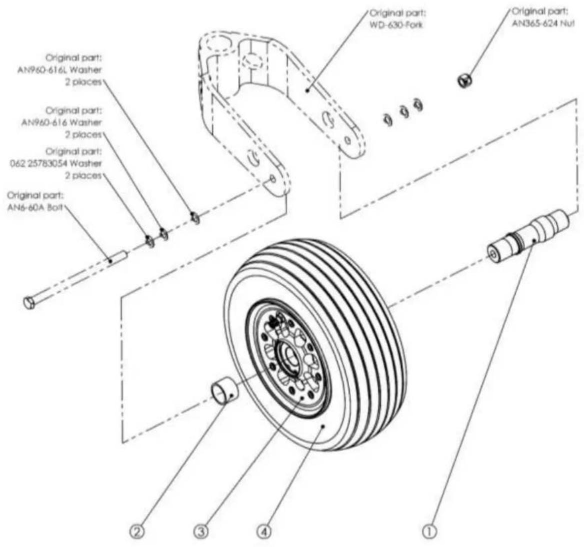
| 4 | PACDI | The 11s4.00x5" | 1 |
| 3 | BA-G15(A) | Wheel Assy. | 1 |
| 2 | AV-VANS-004(A) | Bearing spacer | 1 |
| 1 | AV-VANS-001(A) | Axie rouse AV BVTA | 1 |
| REP | PART NUMBER | DESCRIPTION | QTY. |
| Nature du document :Installation and Maintenance Manual | Ref document:BRG-MM-002(A) |
| Van'sRV3,RV4,RV6,RV6A,RV7,RV7A,RV8,RV8A,RV9,RV9A,RV10,RV12,RV14 and RV14A | Page7 / 73 |
3.2. RV10 and RV14A

| 4 | FAA02 | Tire 5.00-5 TUBELESS | 1 |
| 3 | AV-VANS-010(A) | Axle | 1 |
| 2 | AV-VANS-004(A) | Bearing spacer | 1 |
| 1 | RA-014(A) | Wheel Assy. | 1 |
| REP | PART NUMBER | DESCRIPTION | QTY. |
| Nature du document :Installation and Maintenance Manual | Ref document:BRG-MM-002(A) |
| Van'sRV3,RV4,RV6,RV6A,RV7,RV7A,RV8,RV8A,RV9,RV9A,RV10,RV12,RV14 and RV14A | Page8 / 73 |
4. Finishing Kit for main wheels
4.1. RV3
4.1.1. Main wheel Assy Right (Drawing reference: AV-VANS-320R)

| 14 | - | Safety Wire | 1 |
| 13 | Tree | Tree 11x4.00-5 | 1 |
| 12 | ANA-TA | Boat | 2 |
| 11 | ANA-11A | Boat | 2 |
| 10 | NA31-APPG00P | Weather | 4 |
| 9 | V-V-003 | Coiliter Pin | 1 |
| 8 | V-BHC-004(A) | Screw | 1 |
| 7 | E-MN-003 | Self-locking Nut | 5 |
| 6 | V-87-001 | Screw | 1 |
| 5 | RDL-006(A) | Splicer | 2 |
| 4 | AV-VAN5-005(A) | Nut1.25X16 | 1 |
| 3 | AV-VAN5-003(A) | Coilower piece | 1 |
| 2 | EA-003(N)(A) | Brake Assy | 1 |
| 1 | FI-020(A) | Main Wheel Assy | 1 |
| SEP | PART NUMBER | DESCRIPTION: | QTY |
4.1.2. Main wheel Assy Left (Drawing reference: AV-VANS-320L)
Same assembly AV-VANS-320R (Symmetrical assembly)
| Nature du document :Installation and Maintenance Manual | Ref document:BRG-MM-002(A) |
| Van'sRV3,RV4,RV6,RV6A,RV7,RV7A,RV8,RV8A,RV9,RV9A,RV10,RV12,RV14 and RV14A | Page9 / 73 |
4.1.3. Hose Main wheel Assy Right and Left (Drawing reference: AV-VANS-410)

| 6 | HYD-02BD | PD' ElBox | 1 |
| 5 | HYD-00BCP | Racccordi Termeille 3.8x24 | 1 |
| 4 | HYD-002P | Banjo Boil | 1 |
| 3 | HYD-005B | Copper Seal | 2 |
| 2 | HYD-032 | Quitte felsala non-golini | 1 |
| 1 | HYD-002CP | Banjo | 1 |
| REP | PART NUMBER | DESCRIPTION | QTY. |
| Nature du document :Installation and Maintenance Manual | Ref document:BRG-MM-002(A) |
| Van'sRV3,RV4,RV6,RV6A,RV7,RV7A,RV8,RV8A,RV9,RV9A,RV10,RV12,RV14 and RV14A | Page10 / 73 |
4.1.4. Installation Main wheel Assy Right and left (Drawing reference: AV-VANS-320R)
a) Assemble the brake caliper on the landing gear.

| Nature du document :Installation and Maintenance Manual | Ref document:BRG-MM-002(A) |
 | Van'sRV3,RV4,RV6,RV6A,RV7,RV7A,RV8,RV8A,RV9,RV9A,RV10,RV12,RV14 and RV14A | Page11 / 73 |
b) Assemble the brake caliper on the landing gear.

| Nature du document :Installation and Maintenance Manual | Ref document:BRG-MM-002(A) |
 | Van'sRV3,RV4,RV6,RV6A,RV7,RV7A,RV8,RV8A,RV9,RV9A,RV10,RV12,RV14 and RV14A | Page12 / 73 |
c) Assemble the main wheel


| Nature du document :Installation and Maintenance Manual | Ref document:BRG-MM-002(A) |
| Van'sRV3,RV4,RV6,RV6A,RV7,RV7A,RV8,RV8A,RV9,RV9A,RV10,RV12,RV14 and RV14A | Page13 / 73 |
4.2. RV4, RV6, RV6A, RV7, RV7A, RV8A, RV9 and RV9A
4.2.1. Main wheel Assy Right (Drawing reference: AV-VANS-620R)

| 14 | - | Safety Wire | 1 |
| 13 | FAA02 | FAA02 | 1 |
| 12 | ANA-7A | Bolt | 2 |
| 11 | ANA-11A | Bolt | 2 |
| 10 | NAST-MPO430F | Weather | 4 |
| 9 | L.V-003 | Coilter Pin | 1 |
| 8 | V-BHC-004(A) | Screw | 1 |
| 7 | E-HV-003 | soft looking Nut | 5 |
| 6 | V-EP-001 | Screw | 1 |
| 5 | KD-006(A) | Spacer | 3 |
| 4 | AV-VANS-003(A) | MLT1.25X1a | 1 |
| 3 | AV-VANS-003(A) | Colour slide | 1 |
| 2 | LA-002(N) | Broke Assy | 1 |
| 1 | IP-022(A) | Main Wheel Assy. | 1 |
| REF | PART NUMBER | DESCRIPTION | QTY. |
4.2.2. Main wheel Assy Left (Drawing reference: AV-VANS-620L)
Same assembly AV-VANS-620R (Symmetrical assembly)
| Nature du document :Installation and Maintenance Manual | Ref document:BRG-MM-002(A) |
| Van'sRV3,RV4,RV6,RV6A,RV7,RV7A,RV8,RV8A,RV9,RV9A,RV10,RV12,RV14 and RV14A | Page14 / 73 |
4.2.3. Hose Main wheel Assy Right and Left (Drawing reference: AV-VANS-610)

Note:
Qty 10 ZGA01 Brake line Clamp
| 6 | HYD-024D | Adaptator | 1 |
| 5 | HYD-008OP | Raccord fermete 3.8x24 (Réf O: 6001-03P) | 1 |
| 4 | HYD-0058 | Copper Seal | 2 |
| 3 | HYD-003P | Banjo Boit | 1 |
| 2 | HYD-002OP | Banjo | 1 |
| 1 | HYD-032 | Durife tressée non gainé (Néf O:600-03) | 1 |
| REF | PART NUMBER | DESCRIPTION | QTY. |
| Nature du document :Installation and Maintenance Manual | Ref document:BRG-MM-002(A) |
| Van'sRV3,RV4,RV6,RV6A,RV7,RV7A,RV8,RV8A,RV9,RV9A,RV10,RV12,RV14 and RV14A | Page15 / 73 |
4.2.4. Installation Main wheel Assy Right and left (Drawing reference: AV-VANS-620R)
a) Assemble the caliper plate on the landing gear.

| Nature du document :Installation and Maintenance Manual | Ref document:BRG-MM-002(A) |
| Van'sRV3,RV4,RV6,RV6A,RV7,RV7A,RV8,RV8A,RV9,RV9A,RV10,RV12,RV14 and RV14A | Page16 / 73 |
b) Assemble the brake caliper on the landing gear.
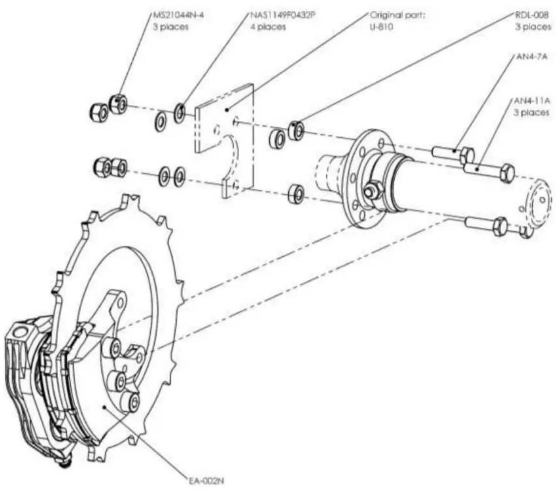
| Nature du document :Installation and Maintenance Manual | Ref document:BRG-MM-002(A) |
 | Van'sRV3,RV4,RV6,RV6A,RV7,RV7A,RV8,RV8A,RV9,RV9A,RV10,RV12,RV14 and RV14A | Page17 / 73 |
c) Assemble the main wheel

| Nature du document :Installation and Maintenance Manual | Ref document:BRG-MM-002(A) |
| Van'sRV3,RV4,RV6,RV6A,RV7,RV7A,RV8,RV8A,RV9,RV9A,RV10,RV12,RV14 and RV14A | Page18 / 73 |
4.3. RV8 Grove Landing Gear
4.3.1. Main wheel Assy Left (Drawing reference: AV-VANS-420L)

| 13 | Safary Wire | 1 | |
| 12 | MS210496-4 | self-kocking Nut | 4 |
| 11 | L-V-054 | Coather Pie | 1 |
| 10 | FAA02 | FAA02 | 1 |
| 9 | V-FHC-007 | Screw | 3 |
| 8 | E-HH-003 | self-kocking Nut | 3 |
| 7 | HA5114904207 | Washer | 8 |
| 6 | A7A8-17A | Axle bolt | 2 |
| 5 | A7A8-22A | Axle bolt | 2 |
| 4 | R1-01(EA) | Main Wheel Assy. | 1 |
| 3 | EA-002N(A) | Brake Assy | 1 |
| 2 | ECF-002(3) | Axle nut | 1 |
| 1 | FUS-008-2(B) | Axle | 1 |
| BSP | PART NUMBER | DESCRIPTION | QTY.. |
4.3.2. Main wheel Assy Right (Drawing reference: AV-VANS-420R)
Same assembly AV-VANS-420L (Symmetrical assembly).
| Nature du document :Installation and Maintenance Manual | Ref document:BRG-MM-002(A) |
| Van'sRV3,RV4,RV6,RV6A,RV7,RV7A,RV8,RV8A,RV9,RV9A,RV10,RV12,RV14 and RV14A | Page19 / 73 |
4.3.3. Hose Main wheel Assy Right and Left (Drawing reference: AV-VANS-410)
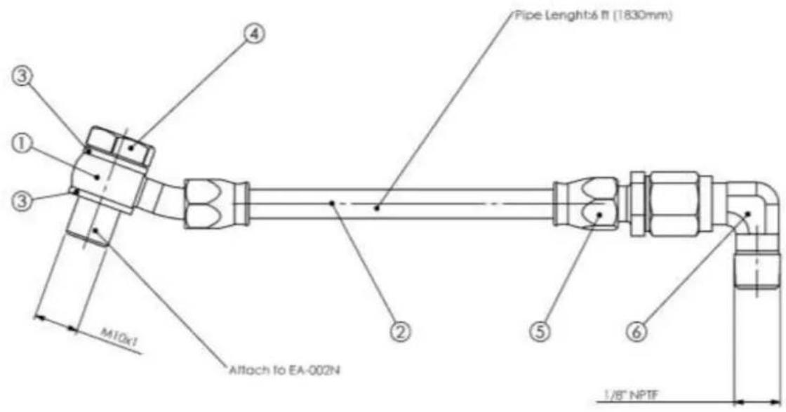
| 6 | HYD-02BD | PD' ElBox | 1 |
| 5 | HYD-00BCP | Racccordi Termeille 3.9c24 | 1 |
| 4 | HYD-002P | Banjo Boil | 1 |
| 3 | HYD-005B | Copper Seal | 2 |
| 2 | HYD-032 | Quitte felsala non-golini | 1 |
| 1 | HYD-002CP | Banjo | 1 |
| REP | PART NUMBER | DESCRIPTION | QTY. |
| Nature du document :Installation and Maintenance Manual | Ref document:BRG-MM-002(A) |
| Van'sRV3,RV4,RV6,RV6A,RV7,RV7A,RV8,RV8A,RV9,RV9A,RV10,RV12,RV14 and RV14A | Page20 / 73 |
4.3.4. Installation Main wheel Assy Right and left (Drawing reference: AV-VANS-420L)
a) This assembly is mounted in factory.
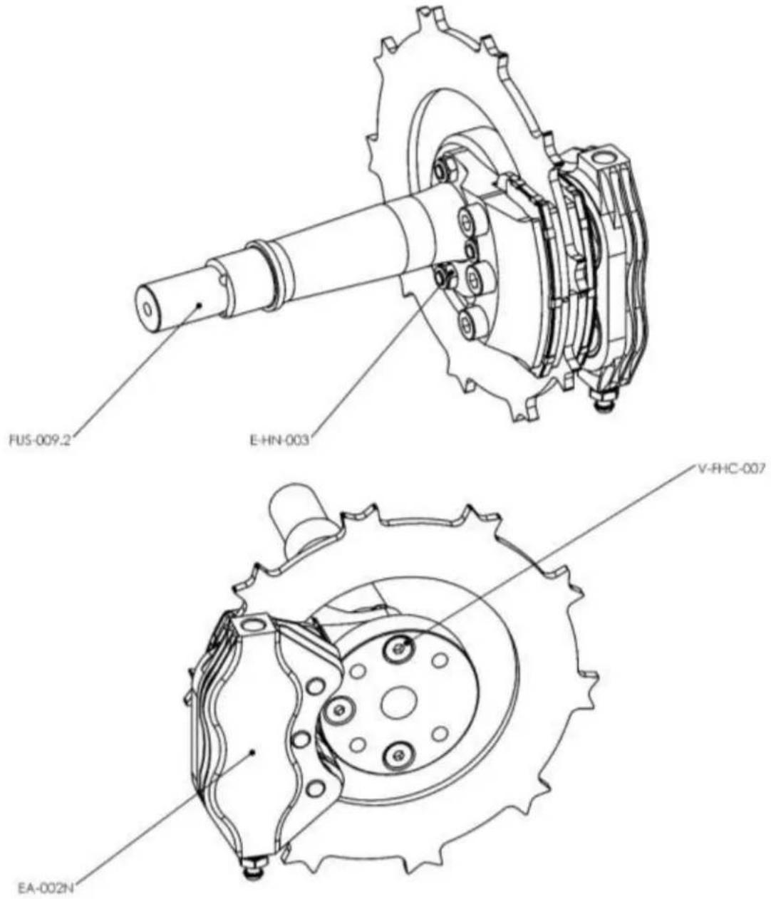
| Nature du document :Installation and Maintenance Manual | Ref document:BRG-MM-002(A) |
| Van'sRV3,RV4,RV6,RV6A,RV7,RV7A,RV8,RV8A,RV9,RV9A,RV10,RV12,RV14 and RV14A | Page21 / 73 |
b) Assemble the brake caliper on the landing gear.

| Nature du document :Installation and Maintenance Manual | Ref document:BRG-MM-002(A) |
 | Van'sRV3,RV4,RV6,RV6A,RV7,RV7A,RV8,RV8A,RV9,RV9A,RV10,RV12,RV14 and RV14A | Page22 / 73 |
c) Assemble the main wheel
![Safety Wire L-V-004 ECR-002[B] RF-018 PAA02](/content/2026/05/841370/images/e612d40f0c6f856708c408be5d671728da5ea8e6de6f24fc9bb6ce0ce192d0af.jpg)
| Nature du document :Installation and Maintenance Manual | Ref document:BRG-MM-002(A) |
| Van'sRV3,RV4,RV6,RV6A,RV7,RV7A,RV8,RV8A,RV9,RV9A,RV10,RV12,RV14 and RV14A | Page23 / 73 |
4.4. RV10
4.4.1. Main wheel Assy Left (Drawing reference: AV-VANS-520L)

| 15 | - | Safety Wire | 1 |
| 14 | 025-501-1 | See 15x1.00-6 | 1 |
| 13 | NAST L4910420F | Washer | 3 |
| 12 | L-V-005 | Coiler Pin | 1 |
| 11 | ANA-11A | Bolt | 1 |
| 10 | ANA-15A | Bolt | 2 |
| 9 | ANA-6A | Bolt | 2 |
| 8 | M521040-4 | Self looking Nut | 5 |
| 7 | EA-003.3N(5) | Brake Assy. | 1 |
| 6 | RF-016(A) | Wheel Assy. | 1 |
| 5 | BOE-017.1(A) | Spacer | 1 |
| 4 | AV-VANS-016(A) | Left Spacer | 1 |
| 3 | AV-VANS-014(B) | Axle | 1 |
| 2 | AV-VANS-011(B) | Axle | 1 |
| 1 | AV-VANS-012(A) | Nut | 1 |
| Item | PART NUMBER | Description | QTY |
4.4.2. Main wheel Assy Right (Drawing reference: AV-VANS-520R)
Same assembly AV-VANS-520L (Symmetrical assembly) Replace Item 04 (AV-VANS-016L) by (AV-VANS-016R)
| Nature du document :Installation and Maintenance Manual | Ref document:BRG-MM-002(A) |
| Van'sRV3,RV4,RV6,RV6A,RV7,RV7A,RV8,RV8A,RV9,RV9A,RV10,RV12,RV14 and RV14A | Page24 / 73 |
4.4.3. Hose Main wheel Assy Right and Left (Drawing reference: AV-VANS-510)
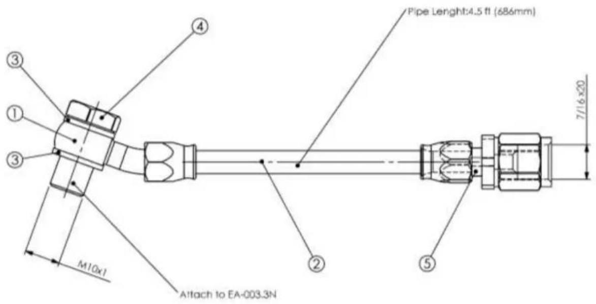
Note:
Qty 10 ZGA01 Brake line Clamp
| 5 | HYD-009OC | Raccord draft 7/16x20 | 1 |
| 4 | HYD-003P | Banjo Boil | 1 |
| 3 | HYD-005B | Copper Seal | 2 |
| 2 | HYD-032 | Duttle tressée non gainé | 1 |
| 1 | HYD-002OP | Banjo | 1 |
| REF | PART NUMBER | DESCRIPTION | QTY. |
| Nature du document :Installation and Maintenance Manual | Ref document:BRG-MM-002(A) |
| Van'sRV3,RV4,RV6,RV6A,RV7,RV7A,RV8,RV8A,RV9,RV9A,RV10,RV12,RV14 and RV14A | Page25 / 73 |
4.4.4. Installation Main wheel Assy Right and left (Drawing reference: AV-VANS-520L)
a) Assemble the left brake assembly using the parts and hardware from the drawing below. (Drilling U-1010-L)

b) Grease the landing gear leg axle and slide the left brake assembly on the axle of the U-1001-L Main Gear leg and secure it in place with the shear pin.

| Nature du document :Installation and Maintenance Manual | Ref document:BRG-MM-002(A) |
| Van'sRV3,RV4,RV6,RV6A,RV7,RV7A,RV8,RV8A,RV9,RV9A,RV10,RV12,RV14 and RV14A | Page26 / 73 |
c) Insert the shear pin.
CAUTION: Make sure that the shear pin is fully in place and that the distance between the disc and the fairing plate is as per the next drawing
![[0,134 ±0,020] 3,40 ±0,5 Shear pin WARNING Torque axle nut to contact by hands, do not force.](/content/2026/05/841370/images/99d8b3713135ada0f48951fe9e194f985e877b0fed3bec7f7db253007fb45e3c.jpg)
d) Apply a thin coat of grease on wheel bearings
Insert the wheel through the axle while placing the disc in wheel slots between the clips.
NOTE: Do not force, the disc has to be properly positioned to fit inside wheel slots.
e) Apply a thin coat of grease on axle thread. Screw the axle nut to contact
f) Torque axle nut to contact by hands, do not force. (WARNING)
g) Insert a new cotter pin to secure the axle nut
CAUTION: Cotter pin must be in place to prevent the loose of axle nut.
| Nature du document :Installation and Maintenance Manual | Ref document:BRG-MM-002(A) |
| Van'sRV3,RV4,RV6,RV6A,RV7,RV7A,RV8,RV8A,RV9,RV9A,RV10,RV12,RV14 and RV14A | Page27 / 73 |
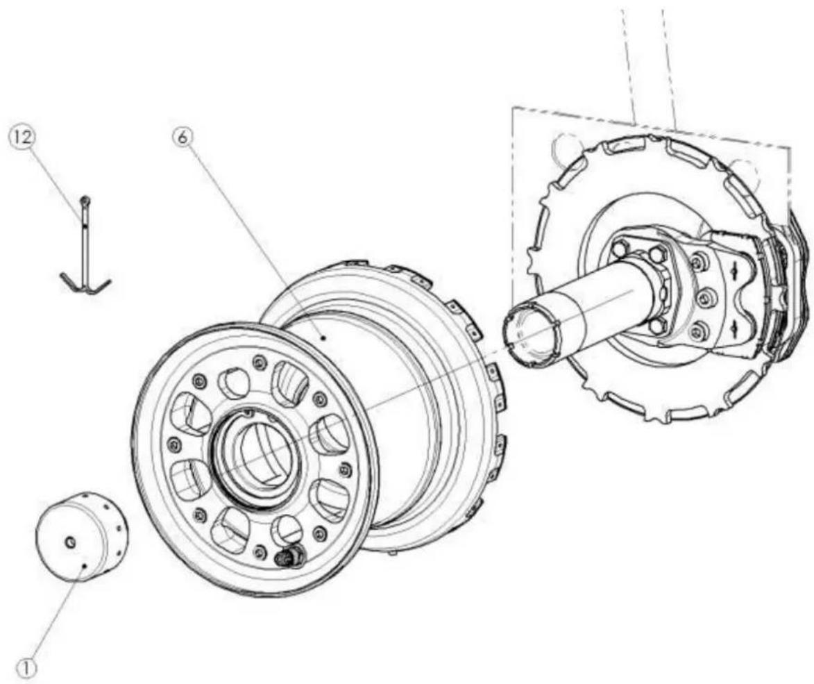
h) Place a new safety wire (stainless steel 1mm - 0.040") in the ring groove all around the wheel. This safety wire must be in place to secure the disc.
| Nature du document :Installation and Maintenance Manual | Ref document:BRG-MM-002(A) |
| Van'sRV3,RV4,RV6,RV6A,RV7,RV7A,RV8,RV8A,RV9,RV9A,RV10,RV12,RV14 and RV14A | Page28 / 73 |
4.5. RV14
4.5.1. Main wheel Assy Left (Drawing reference: AV-VANS-220L)

| 12 | Safety Wire | 1 | |
| 11 | ANA-16A | Screw | 1 |
| 10 | ANA-21A | Screw | 3 |
| 9 | MS21042-4 | Self-locking Nut | 4 |
| 8 | NAS114P10A0P | Washer | 4 |
| 7 | PAA02 | The 5.00-5 TUBELEST | 1 |
| 6 | LV-004 | Cofter Pin | 1 |
| 5 | ECR-002(B) | Axle nut | 1 |
| 4 | PI-01(EA) | Main Wheel Assy. | 1 |
| 3 | V-FHC-007 | Screw | 2 |
| 2 | EA-002,2(NA) | Brake Assy. | 1 |
| 1 | AV-VANS-200(A) | Axle | 1 |
| REF | PART NUMBER | DESCRIPTION | QTY. |
4.5.2. Main wheel Assy Right (Drawing reference: AV-VANS-220R)
Same assembly AV-VANS-220L (Symmetrical assembly).
| Nature du document :Installation and Maintenance Manual | Ref document:BRG-MM-002(A) |
| Van'sRV3,RV4,RV6,RV6A,RV7,RV7A,RV8,RV8A,RV9,RV9A,RV10,RV12,RV14 and RV14A | Page29 / 73 |
4.5.3. Hose Main wheel Assy Right and Left (Drawing reference: AV-VANS-610)

Note:
Qty 10 ZGA01 Brake line Clamp
| 6 | HYD-024D | Adaptator | 1 |
| 5 | HYD-008DF | Raccord fermete 3,8x24 (Réf G: 6001-03P) | 1 |
| 4 | HYD-005B | Copper Seal | 2 |
| 3 | HYD-003P | Banjo Bait | 1 |
| 2 | HYD-002DF | Banjo | 1 |
| 1 | HYD-032 | Durite tressée non gainé (réf G:s00-03) | 1 |
| REF | PART NUMBER | DESCRIPTION | QTY. |
| Nature du document :Installation and Maintenance Manual | Ref document:BRG-MM-002(A) |
| Van'sRV3,RV4,RV6,RV6A,RV7,RV7A,RV8,RV8A,RV9,RV9A,RV10,RV12,RV14 and RV14A | Page30 / 73 |
4.5.4. Installation Main wheel Assy Left and right
a) Assemble the brake caliper on the landing gear.

| Nature du document :Installation and Maintenance Manual | Ref document:BRG-MM-002(A) |
 | Van'sRV3,RV4,RV6,RV6A,RV7,RV7A,RV8,RV8A,RV9,RV9A,RV10,RV12,RV14 and RV14A | Page31 / 73 |
b) Assemble the main wheel

| Nature du document :Installation and Maintenance Manual | Ref document:BRG-MM-002(A) |
| Van'sRV3,RV4,RV6,RV6A,RV7,RV7A,RV8,RV8A,RV9,RV9A,RV10,RV12,RV14 and RV14A | Page32 / 73 |
5. Fuselage Kit
5.1. Fuselage Kit VANS RV6,RV6A,RV7,RV7A,RV9,RV9A,RV10 and RV14.
In the fuselage Kit, BERINGER offers 4 optional.
- Basic Kit only Pilot Master cylinder.
• Basic Kit + Copilote Master cylinder. - Basic Kit only Pilot Master cylinder + Parking brake valve.
- Basic Kit + Copilote Master cylinder + Parking brake valve.
- Regulator Kit.
- Parking brake valve Kit.
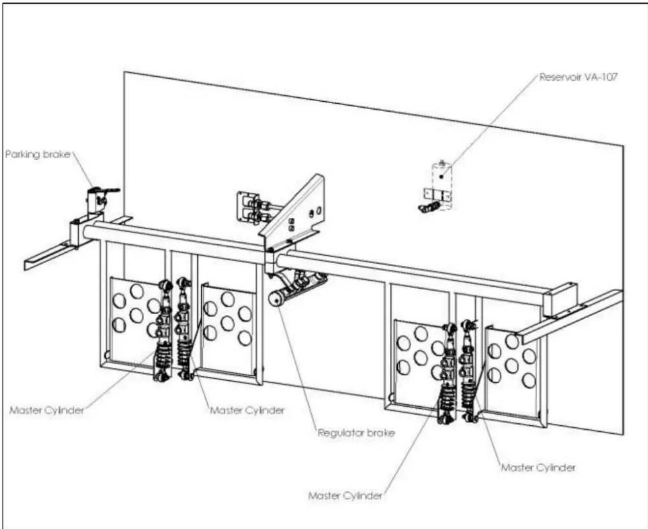
| Nature du document :Installation and Maintenance Manual | Ref document:BRG-MM-002(A) |
| Van'sRV3,RV4,RV6,RV6A,RV7,RV7A,RV8,RV8A,RV9,RV9A,RV10,RV12,RV14 and RV14A | Page33 / 73 |
5.1.1. Complite Hydraulic digram (Drawing reference AV-VANS-550)
5.1.1.1 Basic+parking+copilot+regulator Kit (SRVFU04)+ (SRVFU06).

flowchart
graph TD
    A["Original Part 7/16" Fitting"] -->|Hose 1| B["LH Brake Assembly AV-VANS-520"]
    A -->|Hose 2| C["Parking Brake AV-VANS-580"]
    A -->|Hose 3| D["Regulator Brake AV-VANS-590"]
    A -->|Hose 4| E["Brake Fluid Reservoir AV-VANS-570"]
    A -->|Hose 5| F["Pilot LH Master Cylinder Assembly AV-VANS-560"]
    A -->|Hose 6| G["Co-Pilot RH Master Cylinder Assembly AV-VANS-560"]
    A -->|Hose 7| H["Rh Brake Assembly"]
    C -->|Hose 2| I["F-6122-1 Ttl gear Brake Bracket AN833-4D Replace by AN832-4D"]
    D -->|Hose 3| J["F-6122-1 Ttl gear Brake Bracket AN833-4D Replace by AN832-4D"]
    E -->|Hose 4| K["F-6122-1 Ttl gear Brake Bracket AN833-4D Replace by AN832-4D"]
    F -->|Hose 5| L["Pilot LH Master Cylinder Assembly AV-VANS-560"]
    G -->|Hose 6| M["Co-Pilot RH Master Cylinder Assembly AV-VANS-560"]
    H -->|Hose 7| N["Rh Brake Assembly"]
    I -->|Hose 2| O["F-6122-1 Ttl gear Brake Bracket AN833-4D Replace by AN832-4D"]
    J -->|Hose 3| P["F-6122-1 Ttl gear Brake Bracket AN833-4D Replace by AN832-4D"]
    K -->|Hose 4| Q["F-6122-1 Ttl gear Brake Bracket AN833-4D Replace by AN832-4D"]
    L -->|Hose 5| R["F-6122-1 Ttl gear Brake Bracket AN833-4D Replace by AN832-4D"]
    M -->|Hose 6| S["F-6122-1 Ttl gear Brake Bracket AN833-4D Replace by AN832-4D"]
    N -->|Hose 7| T["F-6122-1 Ttl gear Brake Bracket AN833-4D Replace by AN832-4D"]
    O -->|Hose 8| U["F-6122-1 Ttl gear Brake Bracket AN833-4D Replace by AN832-4D"]
| Nature du document :Installation and Maintenance Manual | Ref document:BRG-MM-002(A) |
| Van'sRV3,RV4,RV6,RV6A,RV7,RV7A,RV8,RV8A,RV9,RV9A,RV10,RV12,RV14 and RV14A | Page34 / 73 |
5.1.1.2 Basic+parking+copilot Kit(SRVFU04)

flowchart
graph TD
    A["Original Pipe"] --> B["Original Part 7/16" Fitting"]
    B --> C["Hose 1"]
    C --> D["LH Brake Assembly AV-VANS-520L"]
    D --> E["Ground"]
    F["Parking Brake AV-VANS-580"] --> G["Hose 2"]
    G --> H["F-6122-1 Tri gear Brake Bracket AN833-4D Replace by AN832-4D"]
    F --> I["Hose 7"]
    I --> J["Pilot LH Master Cylinder Assembly AV-VANS-560"]
    I --> K["Pilot LH Master Cylinder Assembly AV-VANS-560"]
    I --> L["Co-Pilot RH Master Cylinder Assembly AV-VANS-560"]
    I --> M["Co-Pilot RH Master Cylinder Assembly AV-VANS-560"]
    N["Brake Fluid Reservoir AV-VANS-570"] --> O["Hose 6"]
    O --> P["Original Part 7/16" Fitting"]
    P --> Q["F-6122-1 Tri gear Brake Bracket AN833-4D Replace by AN832-4D"]
    P --> R["Original Pipe"]
    S["Rh Brake Assembly AV-VANS-520R"] --> T["Hose 1"]
    T --> U["Ground"]
    V["Hose 5"] --> W["Pilot LH Master Cylinder Assembly AV-VANS-560"]
    V --> X["Pilot LH Master Cylinder Assembly AV-VANS-560"]
    V --> Y["Co-Pilot RH Master Cylinder Assembly AV-VANS-560"]
    V --> Z["Co-Pilot RH Master Cylinder Assembly AV-VANS-560"]
| Nature du document :Installation and Maintenance Manual | Ref document:BRG-MM-002(A) |
| Van'sRV3,RV4,RV6,RV6A,RV7,RV7A,RV8,RV8A,RV9,RV9A,RV10,RV12,RV14 and RV14A | Page35 / 73 |
flowchart
graph TD
    A["Original Part 7/16" Fitting"] --> B["F-6122-1 Tri gear Brake Bracket AN833-4D Replace by AN832-4D"]
    A --> C["Original Part"]
    C --> D["F-6122-1 Tri gear Brake Bracket AN833-4D Replace by AN832-4D"]
    C --> E["Original Part 7/16" Fitting"]
    E --> F["F-6122-1 Tri gear Brake Bracket AN833-4D Replace by AN832-4D"]
    C --> G["LH Brake Assembly AV-VANS-520L"]
    C --> H["Pilot LH Master Cylinder Assembly AV-VANS-560"]
    C --> I["Pilot LH Master Cylinder Assembly AV-VANS-560"]
    C --> J["Co-Pilot RH Master Cylinder Assembly AV-VANS-560"]
    C --> K["Co-Pilot RH Master Cylinder Assembly AV-VANS-560"]
    C --> L["RH Brake Assembly AV-VANS-520R"]
    M["Hose 1"] --> N["LH Brake Assembly AV-VANS-520L"]
    O["Hose 2"] --> P["Pilot LH Master Cylinder Assembly AV-VANS-560"]
    O --> Q["Co-Pilot RH Master Cylinder Assembly AV-VANS-560"]
    R["Hose 3"] --> S["Pilot LH Master Cylinder Assembly AV-VANS-560"]
    R --> T["Co-Pilot RH Master Cylinder Assembly AV-VANS-560"]
    U["Hose 4"] --> V["Pilot LH Master Cylinder Assembly AV-VANS-560"]
    U --> W["Co-Pilot RH Master Cylinder Assembly AV-VANS-560"]
    X["Hose 5"] --> Y["Pilot LH Master Cylinder Assembly AV-VANS-560"]
    X --> Z["Co-Pilot RH Master Cylinder Assembly AV-VANS-560"]
    AA["Hose 6"] --> AB["Pilot LH Master Cylinder Assembly AV-VANS-560"]
    AA --> AC["Co-Pilot RH Master Cylinder Assembly AV-VANS-560"]
    AD["VENT"] --> AE["Brake Fluid Reservoir AV-VANS-570"]
    AE --> AF["Co-Pilot RH Master Cylinder Assembly AV-VANS-560"]
    AG["Original Part 7/16" Fitting"] --> AH["Pilot LH Master Cylinder Assembly AV-VANS-560"]
    AG --> AI["Pilot LH Master Cylinder Assembly AV-VANS-560"]
    AG --> AJ["Co-Pilot RH Master Cylinder Assembly AV-VANS-560"]
    AG --> AK["RH Brake Assembly AV-VANS-520R"]
| Nature du document :Installation and Maintenance Manual | Ref document:BRG-MM-002(A) |
| Van'sRV3,RV4,RV6,RV6A,RV7,RV7A,RV8,RV8A,RV9,RV9A,RV10,RV12,RV14 and RV14A | Page36 / 73 |
flowchart
graph TD
    A["Original Pipe"] --> B["F-6122-1 Tri gear Brake Bracket AN833-4D Replace by AN832-4D"]
    A --> C["Original Part 7/16" Fitting"]
    C --> D["Original Part 7/16" Fitting"]
    D --> E["Pilot LH Master Cylinder Assembly AV-VANS-S60"]
    D --> F["Pilot LH Master Cylinder Assembly AV-VANS-S60"]
    E --> G["Hose 9"]
    F --> H["Hose 9"]
    G --> I["LH Brake Assembly AV-VANS-S20L"]
    H --> J["RH Brake Assembly AV-VANS-S20R"]
    K["Hose 8"] --> L["F-6122-1 Tri gear Brake Bracket AN833-4D Replace by AN832-4D"]
    K --> M["Brake Fluid Reservoir AV-VANS-570"]
    N["Hose 1"] --> O["RH Brake Assembly AV-VANS-S20R"]
    P["Hose 9"] --> Q["Pilot LH Master Cylinder Assembly AV-VANS-S60"]
    P --> R["Pilot LH Master Cylinder Assembly AV-VANS-S60"]
    Q --> S["BRake Fluid Reservoir AV-VANS-570"]
    R --> T["BRake Fluid Reservoir AV-VANS-570"]
    U["Ground"] --> V["Ground"]
| Nature du document :Installation and Maintenance Manual | Ref document:BRG-MM-002(A) |
| Van'sRV3,RV4,RV6,RV6A,RV7,RV7A,RV8,RV8A,RV9,RV9A,RV10,RV12,RV14 and RV14A | Page37 / 73 |
5.1.2. Brake line
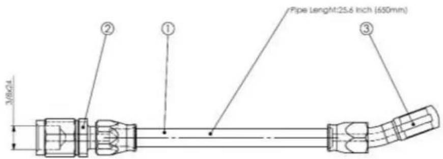
5.1.2.1 Hose 01 (Main wheel / Fuselage)
• For RV 3 see §4.1.3
• For RV 4,6,6A,7,7A,8A,9 and 9A see §4.2.3
• For RV 8 see §4.3.3
• For RV 10 see §4.4.3
• For RV 14 see §4.5.3
5.1.2.2 Hose 02 (Fuselage/FP)

| B | H17-000F | Roccaord network 3.8x24 | 1 |
| T | H18-RPOC | Roccaord network 2.5x25 | 1 |
| I | =V-DOS | Dutler mobile phone port | 1 |
| PBT | PART MANUAL | DISCK/FOX | QTY |
| Nature du document :Installation and Maintenance Manual | Ref document:BRG-MM-002(A) |
| Van'sRV3,RV4,RV6,RV6A,RV7,RV7A,RV8,RV8A,RV9,RV9A,RV10,RV12,RV14 and RV14A | Page38 / 73 |
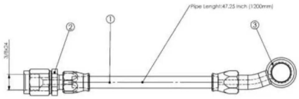
5.1.2.3 Hose 03 (FP/Regulator)
| 3 | HVD-DRGDP | Burku | 1 |
| 2 | HVD-DRGDP | Ilocord-Neville-John | 1 |
| 1 | HVD-GDZ | Durte reselle-non-jointe | 1 |
| KDP | PART NUMBER | DESCRIPTION | QTY. |
5.1.2.4 Hose 04 (Regulator/MC Pilot)

| 2 | RFD-GETUP | Barlo | 1 |
| 3 | RFD-DBFOP | Roccioid barlo to 3.8x24 | 1 |
| 4 | METHESI | Durfe tensile non game | 1 |
| 5EP | PART NUMBER | DESCRIPTION | QTY |
| Nature du document :Installation and Maintenance Manual | Ref document:BRG-MM-002(A) |
| Van'sRV3,RV4,RV6,RV6A,RV7,RV7A,RV8,RV8A,RV9,RV9A,RV10,RV12,RV14 and RV14A | Page39 / 73 |
5.1.2.5 Hose 05 (MC Pilot/MC Copilot)
| 3 | H10-022GP | Bono | I |
| 2 | H10-038OP | Roscord ternale 3.8x34 | I |
| 1 | H10-033 | Dutte hexilee non golink | I |
| REF | PART NUMBER | DESCRIPTION | QTY |
5.1.2.6 Hose 06 (MC Copilot-Reservoir)

| 3 | H1D-020F | Bonjo | 1 |
| 2 | H1D-080F | Roccardi fermelle 3.8x24 | 1 |
| 1 | H1D-032 | Durée tressée non gainé | 1 |
| REF | PART NUMBER | DESCRIPTION | QTY: |
| Nature du document :Installation and Maintenance Manual | Ref document:BRG-MM-002(A) |
| Van'sRV3,RV4,RV6,RV6A,RV7,RV7A,RV8,RV8A,RV9,RV9A,RV10,RV12,RV14 and RV14A | Page40 / 73 |
5.1.2.7 Hose 07 (MC pilot-FP)

| P | H10-0210CF | Tangai ke## 357 | 1 |
| I | H10-0280CF | Fingyai San#o 35904 | 1 |
| A | A1.2102 | Shinwei Deelkender Focus | 1 |
| BP | FAET-06140CF | Zhangy##i | 027 |
5.1.2.8 Hose 08 (Fuselage -MC pilot)
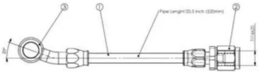
| 1 | P = O + 2O / g | Tensile BP | 1 |
| 2 | P = O + 2O/g | Finger bridle (10x3) | 1 |
| 3 | P = O + 2O/g | Hammee rail motor frame | 1 |
| 42 | P = O + 2O/g | Diameter | U/s |
| Nature du document :Installation and Maintenance Manual | Ref document:BRG-MM-002(A) |
| Van'sRV3,RV4,RV6,RV6A,RV7,RV7A,RV8,RV8A,RV9,RV9A,RV10,RV12,RV14 and RV14A | Page41 / 73 |
5.1.2.9 Hose 09 (MC pilot-Reservoir)

| 2 | HYD-0380P | Straight furnace Jellack | 2 |
| 1 | HYD-032 | Stainless steel Brake Hose | 1 |
| REP | FART NUMBER | Designation | QTY |
| Nature du document :Installation and Maintenance Manual | Ref document:BRG-MM-002(A) |
| Van'sRV3,RV4,RV6,RV6A,RV7,RV7A,RV8,RV8A,RV9,RV9A,RV10,RV12,RV14 and RV14A | Page42 / 73 |
5.1.3. Assembly Master cylinder right and left (Drawing reference AV-VANS-560)

| 1 | ### | ### | 2 |
| 2 | ### | ### | 2 |
| 3 | ### | ### | 1 |
| 4 | ### | ### | 1 |
| 5 | ### | ### | 1 |
| 6 | ### | ### | 0 |
| 7 | ### | ### | 0 |
| ### | ### | 1 | |
| ## | ### | ### | 1 |

| 1 | NATC004 | NATC004-16 | 1 |
| 2 | PRT 25 | PRT 25 | 2 |
| 3 | NATC004 | NATC004 | 3 |
| 4 | NATC004 | NATC004 | 4 |
| 5 | NATC004 | NATC004 | 5 |
| 6 | NATC004 | NATC004 | 6 |
| 7 | NATC004 | NATC004 | 7 |
| 8 | NATC004 | NATC004 | 8 |
| 9 | NATC004 | NATC004 | 9 |
| 10 | NATC004 | NATC004 | 10 |
5.1.4. Assembly Brake reservoir (Drawing reference AV-VANS-570)

| 1 | H50025 | Adaptation | |
| 2 | H50463 | 7.38F | |
| KIF | PART KONDER | DESCRIPTION | OFI |
Installation and Maintenance Manual
Ref document: BRG-MM-002(A)
| Van'sRV3,RV4,RV6,RV6A,RV7,RV7A,RV8,RV8A,RV9,RV9A,RV10,RV12,RV14 and RV14A | Page43 / 73 |
5.1.5. Assembly Parking brake valve(Drawing reference AV-VANS-580)
![F-1039B [3.250] 82.55 F-1039A Rudder Pedal Bearing Block](/content/2026/05/841370/images/683c29ecf9c2603bf0446e9c41f3316893a0086736abcb3623a0bdbe092002b9.jpg)
| 11 | MS21042-4 | Self locking Nut | 2 |
| 10 | NAS114WFG300P | Washer | 4 |
| 9 | AN3-22A | Axis bolt | 2 |
| 8 | E-HN4-002 | self-locking Nut | 2 |
| 7 | V-CHC-041 | Screw | 2 |
| 6 | R-AP-004 | Washer | 8 |
| 5 | HYD-003P | Banjo bolt | 2 |
| 4 | HYD-DYFVC | Banjo | 2 |
| 3 | HYD-005B | Copper Seal | 4 |
| 2 | AV-VANS-D15(A) | Support | 1 |
| 1 | FP-001(A) | Parking Broke | 1 |
| REP | PART NUMBER | DESCRIPTION | QTY. |
| Nature du document :Installation and Maintenance Manual | Ref document:BRG-MM-002(A) |
| Van'sRV3,RV4,RV6,RV6A,RV7,RV7A,RV8,RV8A,RV9,RV9A,RV10,RV12,RV14 and RV14A | Page44 / 73 |
5.1.6. Assembly Parking brake valve(Drawing reference AV-VANS-590)

| 4 | AV-VAND-ODS (A) | Elbow | 1 |
| 3 | HYD-005B | Copper feedi | 9 |
| 2 | HYD-005P | Banjo Bat | 4 |
| 1 | RE-DOT(8) | Regulator | 1 |
| REF | PART NUMBER | DESCRIPTION | QTY |
| Nature du document :Installation and Maintenance Manual | Ref document:BRG-MM-002(A) |
| Van'sRV3,RV4,RV6,RV6A,RV7,RV7A,RV8,RV8A,RV9,RV9A,RV10,RV12,RV14 and RV14A | Page45 / 73 |
6. Brake line
A. Banjo Assembly

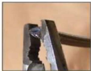
B. Cut the hose

natural_image
Close-up of a hand holding a metal tool with a handle, against a textured background (no text or symbols visible)- Using a fine tooth saw blade or cutter plier, cut hose to the required length.
- Clean any loose debris from both the cut ends and inside the hose.
- Then use a flat pliers to make the hole circular, as shown on the picture below.
natural_image
Close-up of a metal tool with a metallic bracket and a small hole, against a plain background (no text or symbols visible)
| Nature du document :Installation and Maintenance Manual | Ref document:BRG-MM-002(A) |
| Van'sRV3,RV4,RV6,RV6A,RV7,RV7A,RV8,RV8A,RV9,RV9A,RV10,RV12,RV14 and RV14A | Page46 / 73 |
C. Put the nut in the hose
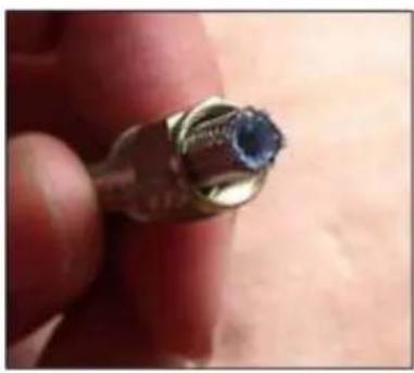
natural_image
Close-up of a finger holding a small metallic object with a blue gemstone (no text or symbols visible)D. Put the olive


natural_image
Close-up of a finger holding a metallic connector with threaded shaft (no visible text or symbols)Push the olive onto the end of PTFE inner tube and under the stainless steel braid. Make sure that all stainless steel filaments are outside of the olive.
Make sure that PTFE tube is fully homed in the olive.
E. Put the banjo
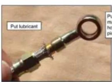
Push between hands the main fitting body and hose as shown on left picture.
Turn with hand the main fitting body to start threading the socket as shown on picture below.
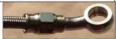
natural_image
Close-up of a metallic mechanical component with threaded end and circular ring (no visible text or symbols)F. Tightening torque the socket

natural_image
Close-up of a hand using a tool to apply material to a surface, with arrows indicating direction (no text or symbols visible)Torque tightening the socket at 10N.m to 15N.m (90 IN-LBS to 132 IN-LBS)
Maintain with wood plates to preserve the main fitting body
Installation and Maintenance Manual
Ref document: BRG-MM-002(A)
| Van'sRV3,RV4,RV6,RV6A,RV7,RV7A,RV8,RV8A,RV9,RV9A,RV10,RV12,RV14 and RV14A | Page47 / 73 |
7. Maintenance
7.1. Equipment concerned
- Nose wheel without brake:
- P/N: RA-014
- 4 main wheels for brake application:
- P/N: RF-016
- P/N: RF-018
• P/N: RF-022
- 4 brake assemblies:
- P/N: EA-002N
• P/N: EA-002.2N
• P/N: EA-003.3N
Notes :
- L and R indicates the Left and Right brake assemblies
7.2. Quick Reference Specifications
7.2.1. Tires:
| Wheel | Tire Size | Type | Max. Inflation pressure |
| RA-014(-)RF-018(-)RF-022(-) | 5.00-5 | Tubeless | 88 PSI |
| RF-016(-) | 15x6.00-6 | Tubeless | 112 PSI |
| Nature du document :Installation and Maintenance Manual | Ref document:BRG-MM-002(A) |
| Van'sRV3,RV4,RV6,RV6A,RV7,RV7A,RV8,RV8A,RV9,RV9A,RV10,RV12,RV14 and RV14A | Page48 / 73 |
7.2.2. Main Wheels:
7.2.2.1 6.00-6 Main wheel assembly RF-016(A):
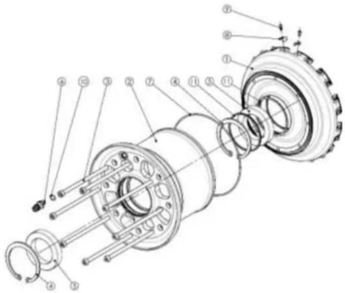
| 11BGE-025(A) Spacer 2 | ||
| 10J-JTR-017N O-Ring 1 | ||
| 9 V-CHC-005 Clip Screw 24 | ||
| 8 CLP-001(B) Clip 24 | ||
| 7 J-JTR-007N O-Ring 1 | ||
| 6 A-001 Valve 1 | ||
| 5 B-BE-014 BEARING 2 | ||
| 4 C-AL-006 CIRCLIP 2 | ||
| 3 V-CHC-004 Screw | 8 | |
| 2 JAE-024(A) Outer Whell half | 1 | |
| 1 JA1-012(B) Inner wheel half | 1 | |
| REP PART NUMBER | DESCRIPTION | QTY. |
| Torque | Threadlocker | ||
| Wheel screw | 12 N.m | 105 in-lb | medium strength (Loctite 243 recommended) |
| Clip screw | 1.5 N.m | 13 in-lb | high strength (Loctite 271 recommended) |
- Clip – disc maximum play: 0.4mm (0.016")
• Disc safety wire::1.01mm (0.040") stainless steel grade 302
| Nature du document :Installation and Maintenance Manual | Ref document:BRG-MM-002(A) |
| Van'sRV3,RV4,RV6,RV6A,RV7,RV7A,RV8,RV8A,RV9,RV9A,RV10,RV12,RV14 and RV14A | Page49 / 73 |
7.2.2.2 5.00-5 Main wheel assembly RF-018(A)

| 12J-JTR-017N O-Ring 1 | |||
| 11A-001 Valve 1 | |||
| 10CLP-002(D) Clip 20 | |||
| 9 V-CHC-005 Clip Screw 20 | |||
| 8 J-JTR-006N C-Ring 1 | |||
| 7 C-AL-002 Circlip 1 | |||
| 6 | C-AL-001 Circlip 1 | ||
| 5 | B-BE-002 Bearing 1 | ||
| 4 | B-BE-001 Bearing 1 | ||
| 3 | V-CHC-020 Assy. Screw 8 | ||
| 2 | JAE-026(A) Outer wheel half | 1 | |
| 1 | JAI-028(A) Inner wheel half | 1 | |
| REP | PART NUMBER | DESCRIPTION | QTY. |
| Torque | Threadlocker | ||
| Wheel screw | 10 N.m | 87 in-lb | medium strength (Loctite 243 recommended) |
| Clip screw | 1.5 N.m | 13 in-lb | high strength (Loctite 271 recommended) |
- Clip – disc maximum play: 0.4mm (0.016")
• Disc safety wire::1.01mm (0.040") stainless steel grade 302
| Nature du document :Installation and Maintenance Manual | Ref document:BRG-MM-002(A) |
| Van'sRV3,RV4,RV6,RV6A,RV7,RV7A,RV8,RV8A,RV9,RV9A,RV10,RV12,RV14 and RV14A | Page50 / 73 |
7.2.2.3 5.00-5 Main wheel assembly RF-022:

| 12A-001 Valve 1 | ||
| 11CLP-002(D) Clip 20 | ||
| 10V-CHC-020 Assy. Screw 8 | ||
| 9 V-CHC-005 Clip Screw 20 | ||
| 8 J-TR-017N O-Ring 1 | ||
| 7 J-JTR-006N | O-Ring | 1 |
| 6 C-AL-002 Clrclip 2 | ||
| 5 B-BE-007 | Bearing | 2 |
| 4 BGE-015(A) Spacer 2 | ||
| 3 AV-VANS-003(A) | Spacer 1 | |
| 2 JAE-028(A) | Outer wheel half | 1 |
| 1 JAI-028(A) Inner wheel half 1 | ||
| REP PART NUMBER | DESCRIPTION | QTY. |
| Torque | Threadlocker | ||
| Wheel screw | 10 N.m | 87 in-lb | medium strength (Loctite 243 recommended) |
| Clip screw | 1.5 N.m | 13 in-lb | high strength (Loctite 271 recommended) |
- Clip – disc maximum play: 0.4mm (0.016")
• Disc safety wire::1.01mm (0.040") stainless steel grade 302
| Nature du document :Installation and Maintenance Manual | Ref document:BRG-MM-002(A) |
| Van'sRV3,RV4,RV6,RV6A,RV7,RV7A,RV8,RV8A,RV9,RV9A,RV10,RV12,RV14 and RV14A | Page51 / 73 |
7.2.3. Nose Wheels:
7.2.3.1 5.00-5 Nose wheel assembly RA-014(A):
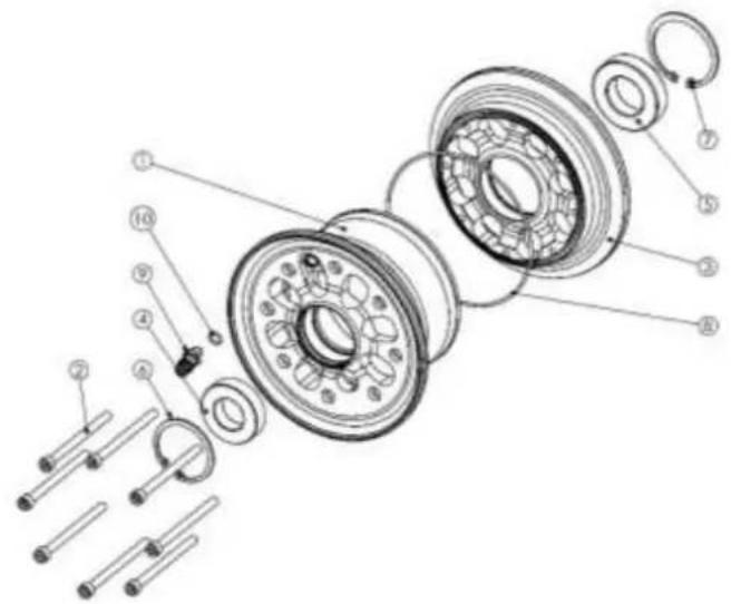
| 10J- | TR-017N O-Ring 1 | ||
| 9 A-001 Valve 1 | |||
| 8 J- | TR-006N O-Ring 1 | ||
| 7 C- | AL-002 Circlip 1 | ||
| 6 C- | AL-001 Circlip 1 | ||
| 5 | B-BE-002 Bearing 1 | ||
| 4 | B-BE-001 Bearing 1 | ||
| 3 | JAI-029(A) Inner Wheel half | 1 | |
| 2 | V-CHC-020 | Assy. Screw | 8 |
| 1 JAE-026(A) Outer wheel half 1 | |||
| REP | PART NUMBER | DESCRIPTION | QTY. |
| Torque | Threadlocker | ||
| Wheel screw | 10 N.m | 87 in-lb | medium strength (Loctite 243 recommended |
7.2.3.2 5.00-5 Nose wheel assembly RA-015(A):

| 10J- JTR-017N O-Ring 1 | ||
| 9 A-001 Valve 1 | ||
| 8 J JTR-006N O-Ring 1 | ||
| 7 C- AL-002 Circlip 1 | ||
| 6 C- AL-001 Circlip 1 | ||
| 5 | B-BE-002 Bearing 1 | |
| 4 | B-BE-001 Bearing 1 | |
| 3 | V-CHC-035 | Assy. Screw 8 |
| 2 | JAI-029(A) | Inner Wheel half 1 |
| 1 JAE-027(A) Outer wheel half 1 | ||
| REP | PART NUMBER | DESCRIPTION QTY. |
| Torque | Threadlocker | ||
| Wheel screw | 10 N.m | 87 in-lb | medium strength (Loctite 243 recommended |
| Nature du document :Installation and Maintenance Manual | Ref document:BRG-MM-002(A) |
| Van'sRV3,RV4,RV6,RV6A,RV7,RV7A,RV8,RV8A,RV9,RV9A,RV10,RV12,RV14 and RV14A | Page52 / 73 |
7.2.4. Brake caliper:
7.2.4.1 Description
Brake caliper are made of aluminium alloy. A thin anodizing coating protects aluminium from corrosion. Anodizing does not protect from nicks and scratches.
Calipers are in 2 separated parts bolted together: the housing with pistons and the back side or back plate.
To assure equal pressure on both brake pads, disc is floating and brake pads can slide on 2 of the 3 assembly screws.


Brake housing is equipped with the same inlet port
on each side to be used on left or right strut of the aircraft. The unused port is sealed by a bleeding screw. Inlet and outlet port have Metric M10x1 internal thread.
Hydraulic fluid MIL-PRF-87257
Lubrication *
Piston Thick silicone grease (-50°C to 200°C) compliant with FDA CFR art. 178.3570
(liquid grease in spray is not allowed)
Piston seal Thick silicone grease (-50°C to 200°C) compliant with FDA CFR art. 178.3570
(liquid grease in spray is not allowed)
* Lubricate cylinder, seal groove, piston seal, and piston with a coat of silicone grease at each time of assembly.
| Nature du document :Installation and Maintenance Manual | Ref document:BRG-MM-002(A) |
| Van'sRV3,RV4,RV6,RV6A,RV7,RV7A,RV8,RV8A,RV9,RV9A,RV10,RV12,RV14 and RV14A | Page53 / 73 |
7.2.4.2 Brake caliper assembly EA-002N(A) / EA-002.2N(-):
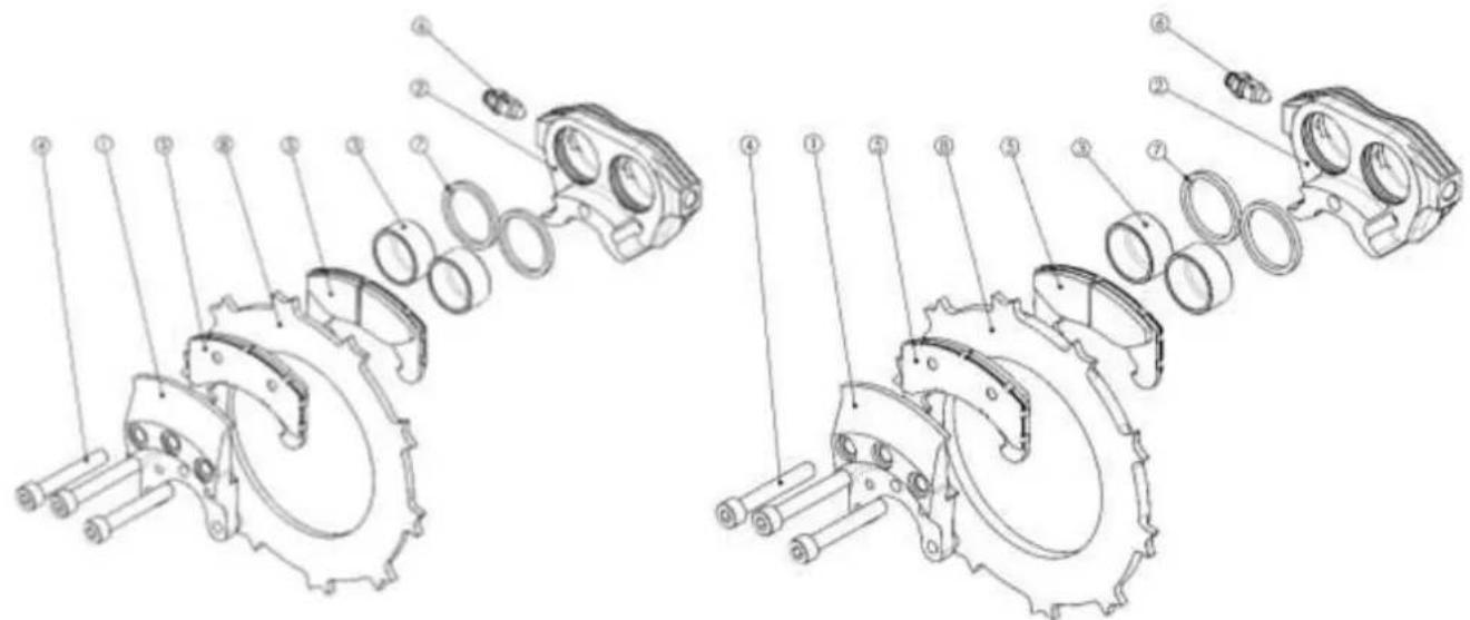
EA-002N(A)
EA-002.2N(A)
| 8 DSC-008(A) Brake dlsc 1 | ||
| 7 JNT-006N(A) Piston seal 2 | ||
| 6 HYD-001P Bleeder 1 | ||
| 5 PQT-009(A) Brake pad 2 | ||
| 4 VIS-003(A) Screw 3 | ||
| 3 PSE-002(A) Piston | 2 | |
| 2 ETR-003(B) Cylinder | 1 | |
| 1 RNF-003(A) Back plate | 1 | |
| REP PART NUMBER | DESCRIPTION | QTY. |
| 8 | DSC-008.2(A) Brake disc 1 | ||
| 7 JNT-006N(A) Piston seal 2 | |||
| 6 HYD-001P Bleeder 1 | |||
| 5 PQT-009(A) Brake pad 2 | |||
| 4 VIS-003(A) Screw 3 | |||
| 3 PSE-002(A) Piston | 2 | ||
| 2 ETR-003(B) Cylinder 1 | |||
| 1 | RNF-003.2(A) Back plate 1 | ||
| REP | PART NUMBER | DESCRIPTION | QTY. |
Assembly screw:
Torque
25 N.m
220 in-lb
Threadlocker
medium strength (Loctite 243 recommended)
Hydraulic fluid
MIL-PRF-87257
Brake Disc DSC-008(-) / DSC-008.2(-):
Max. coning
0.3mm
0.012 in
Max. groove or bump
0.2mm
0.008 in
DSC-008 Minimum thickness
3.8mm
0.150 in
DSC-008.2 Minimum thickness 6.6mm
0.260 in
Brake Pad PQT-009(-):
Minimum thickness of friction material
1.0mm
0.040 in
| Nature du document :Installation and Maintenance Manual | Ref document:BRG-MM-002(A) |
| Van'sRV3,RV4,RV6,RV6A,RV7,RV7A,RV8,RV8A,RV9,RV9A,RV10,RV12,RV14 and RV14A | Page54 / 73 |
7.2.4.3 Brake caliper assembly EA-003.3N(A)

| 10L-V-001 Cotter Pin 2 | ||
| 9 BTR-001(A) Back Stop 2 | ||
| 8 DSC-009.3(A) Brake disc 1 | ||
| 7 JNT-006N(A) Piston seal 2 | ||
| 6 HYD-001P Bleeder 1 | ||
| 5 PQT-010(A) Brake pad 2 | ||
| 4 VIS-006(A) Assy screw 3 | ||
| 3 PSE-004(A) Piston 2 | ||
| 2 ETR-003(B) Cylinder | 1 | |
| 1 RNF-005.1(B) Back plate 1 | ||
| REP PART NUMBER | DESCRIPTION | QTY. |
Assembly screw:
| Torque | 25 N.m | 220 in-lb |
| Threadlocker | medium strength (Loctite 243 recommended) | |
| Brake Disc DSC-009.3(-): | ||
| Max. coning | 0.3mm | 0.012 in |
| Max. groove or bump | 0.2mm | 0.008 in |
| Minimum thickness | 8.4mm | 0.330 in |
Brake Pad PQT-010(-):
| Minimum thickness of friction material | 1.0mm | 0.040 in |
| Nature du document :Installation and Maintenance Manual | Ref document:BRG-MM-002(A) |
| Van'sRV3,RV4,RV6,RV6A,RV7,RV7A,RV8,RV8A,RV9,RV9A,RV10,RV12,RV14 and RV14A | Page55 / 73 |
7.3. Cleaning
The aluminium parts are protected from corrosion with an anodizing coating. This thin coating does not protect against basic agent with pH > 9.
CAUTION: Cleaning the wheel and brake parts with basic agent may remove totally the anodizing coating
Acid agent may also attack the anodizing.
For cleaning the wheel and brake parts we recommend using only water and soap or dry clothes.
7.4. Conditioning Procedure for Brake Pads
When new brake pads have been installed, it is important to condition them properly to obtain the service life designed into them. Rated brake torque value is reached only after a full conditioning of brake pads and disc.
CAUTION: Brake torque value can be only 50% of rated brake torque before the conditioning. It means that even with full brake effort the aircraft will not stop as usual. Pilot must take into consideration this parameter to avoid loose of aircraft control during the conditioning procedure.
CONDITIONNING PROCEDURE:
- Taxi aircraft for 500m (1500 feet) with light brake effort.
- Perform two (2) consecutive stops from 30 – 35 knots down to 5 knots. Apply light brake effort during these two stops; do not try to apply full brake effort.
- Allow the brakes to cool down for 10 to 15 minutes.
- Apply brakes and check for restraint at high static throttle. If brakes hold, conditioning is complete.
- If brakes cannot hold aircraft during static run-up, allow the brakes to cool completely and repeat steps 1 through 4.
This conditioning procedure will wear off high spots and prepare pads and disc friction surfaces. A visual inspection of disc will indicate the pads condition: a smooth surface with light and regular grooves indicates that pads and disc are properly conditioned.
NOTE: A rough surface of disc with deep grooves and isolated bumps indicates that an excessive brake effort has been applied during conditioning. In this case, bumps must be sanded and conditioning procedure repeated.
CAUTION: A wrong conditioning may affect brake performances and increase wear of pads and disc.
| Nature du document :Installation and Maintenance Manual | Ref document:BRG-MM-002(A) |
| Van'sRV3,RV4,RV6,RV6A,RV7,RV7A,RV8,RV8A,RV9,RV9A,RV10,RV12,RV14 and RV14A | Page56 / 73 |
7.5. Scheduled maintenance checks
7.5.1. 100h / Annual inspection
| Inspection | Operation | ||
| Component | Wear limit | 100h | Annual inspection |
| Brake assembly | - | Apply brakes, examine system for leaks | |
| Brake assembly | - | Visual inspection | Check pistons retraction, check bolt torque |
| Brake Pads | 1mm0.040 in | Check brake pad wear | |
| Brake Disc DSC-008 | 3.8 mm0.150 in | Check disc wear | Examine for cracks or corrosionCheck disc wear |
| Brake Disc DSC-008.2 | 6.6 mm0.260 in | Check disc wear | Examine for cracks or corrosionCheck disc wear |
| Wheel - Brake Disc | 0.4 mm0.016 in | Visual inspection | Check play between disc and wheel Clips |
| Main wheels | - | Visual inspection | Examine bearings, valve, axles and wheel flanges |
| Main wheel tires | - | Visual inspectionCheck inflation pressure and wear | |
| Hydraulic Hoses and fittings | - | Examine for damage, leak and corrosion | |
| Nature du document :Installation and Maintenance Manual | Ref document:BRG-MM-002(A) |
| Van'sRV3,RV4,RV6,RV6A,RV7,RV7A,RV8,RV8A,RV9,RV9A,RV10,RV12,RV14 and RV14A | Page57 / 73 |
7.5.2. Safety maintenance checks
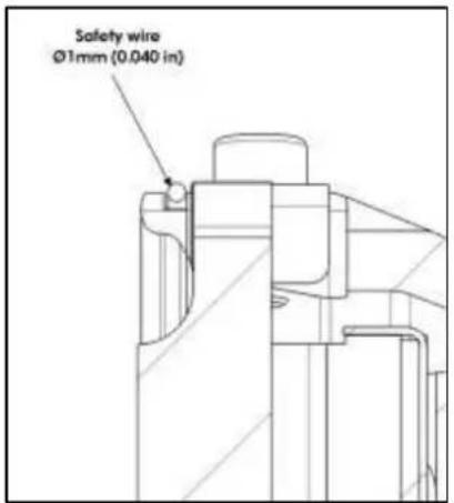
7.5.2.1 Safety wire
Wheel axle and his securing device must be in place.
In case of a main wheel with brake, the safety wire must be in place to prevent the disc from going out the slots.

7.5.2.2 Brake disc

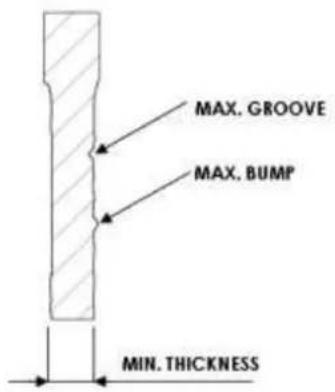
a) Thickness Disc wear limits
| Min Thickness | ||
| DSC-008 | 3.8mm | 0.150" |
| DSC-008.2 | 3.8mm | 0.260" |
| Nature du document :Installation and Maintenance Manual | Ref document:BRG-MM-002(A) |
 | Van'sRV3,RV4,RV6,RV6A,RV7,RV7A,RV8,RV8A,RV9,RV9A,RV10,RV12,RV14 and RV14A | Page58 / 73 |
b) Geometrical Disc wear limits
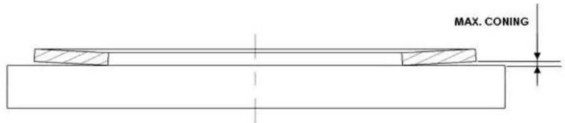
c) Clip wear limits

d) Pad wear limits
Min thickness groove nearly invisible.


BRAKE PAD MUST BE CHANGED BEFORE GROOVE BECAME INVISIBLE
| Nature du document :Installation and Maintenance Manual | Ref document:BRG-MM-002(A) |
| Van'sRV3,RV4,RV6,RV6A,RV7,RV7A,RV8,RV8A,RV9,RV9A,RV10,RV12,RV14 and RV14A | Page59 / 73 |
7.5.3. Replacement schedule of wear parts
| Replacement schedule of wear parts | ||
| Component - item | Note | Replacement schedule |
| Wheel assembly bolts | a | On conditionImmediate replacement if corroded |
| Main wheel bearings | b | On conditionImmediate replacement if corroded or damaged |
| Bearing retaining ring | - | On condition10 years |
| Main Wheel O-ring seals | - | At each tire change5 years |
| Main wheel disc clips | a | On conditionIf found worn, all key disc must be replaced |
| Brake caliper seals and pistons | b | 10 years |
| Brake assembly screws | b | On condition10 years |
| Brake pads | c | On conditionReplace after each brake disc change5 years |
| Brake discs | b | On condition10 years |
| Nature du document :Installation and Maintenance Manual | Ref document:BRG-MM-002(A) |
| Van'sRV3,RV4,RV6,RV6A,RV7,RV7A,RV8,RV8A,RV9,RV9A,RV10,RV12,RV14 and RV14A | Page60 / 73 |
NOTE:
a All screws of the assembly must be changed at the same time. It is not allowed to change only few of them.
b Parts must be changed by pair on both left and right sides at the same time. When new brake discs are installed brake pads must be changed to new ones even if not worn out.
c Brake pads must be changed all 4 at the same time even if not worn out (the 2 on left side and the 2 on right side).
7.5.4. Airworthiness Limitations
a) GENERAL:
This airworthiness limitations Section (ALS) is FAA approved and specifies maintenance required under § 43.16 and 91.403 of the FAR unless an alternate program has been FAA approved.
b) LIFE LIMITED PARTS:
The replacement time of life limited components listed next must be accomplished not later than the specified period of operation for that component.
| Component | Time limit | Maintenance interval | Complete overhaul interval |
| Brake assembly | - | 2500 flying hours or 5 years* | 10,000 flying hours or 20 years* |
| Wheel assembly | - | 1000 flying hours or 10 years* | 10,000 flying hours or 20 years* |
*Whichever limit occurs first
| Nature du document :Installation and Maintenance Manual | Ref document:BRG-MM-002(A) |
| Van'sRV3,RV4,RV6,RV6A,RV7,RV7A,RV8,RV8A,RV9,RV9A,RV10,RV12,RV14 and RV14A | Page61 / 73 |
7.6. Disassembly – Reassembly – Tire change
7.6.1. Disassembly:
WARNING: Do not attempt to disassemble wheel until tire has been completely deflated. Otherwise, serious injury to personnel or damage to equipment can result.
WARNING: Do not attempt to remove valve core until tire has been completely deflated. Valve core will be ejected at high velocities if unscrewed before air pressure has been released.
a) remove wheel from aircraft
b) remove valve cap and apply a tire deflator to release tire pressure completely. Then remove the valve core.
c) break the beads away from the wheel flanges by applying pressure by hand or using a wood or plastic tool as close to the tire bead as possible. Tire lubricant may be used to help. Repeat the operation every 90^ on both sides, see pictures next:


CAUTION: Do not pry between tire bead and wheel flange, this may destroy the structural and sealing properties of the wheel and tire.
d) Remove all screws holding wheel halves together.
CAUTION: Do not use impact or power wrenches
Do not remove assembly screws before the tire beads are fully free from the wheel.
| Nature du document :Installation and Maintenance Manual | Ref document:BRG-MM-002(A) |
| Van'sRV3,RV4,RV6,RV6A,RV7,RV7A,RV8,RV8A,RV9,RV9A,RV10,RV12,RV14 and RV14A | Page62 / 73 |
e) Separate wheel halves, remove the tire and o-ring
f) Carefully lay the wheel halves on a flat clean bench.
CLEANING:
a) Clean all metal parts using water and soap, then wipe dry with a clean cloth. Valve core and central spacer must not be cleaned with solvent.
CAUTION: Do not use basic or acid agent on wheel halves. Anodizing can be totally removed within few minutes in contact with basic agent. Make sure that cleaning soap is not basic.
CAUTION: Sealing of ball bearings must not be damaged or cleaned with solvent.
b) Clean wheel bead seat with dry-cleaning solvent and wipe dry with a clean cloth.
CAUTION: oily solvent must not be used on wheel bead seat because tire will not stick properly on the wheel.
WARNING: Dry-cleaning solvents are toxic and volatile. Use a well-ventilated room. Avoid contact with skin or clothing. Do not inhale the vapor.
c) Apply air pressure to dry internal threads
CAUTION: oily solvent or oily air pressure must not be used on internal thread because threadlocker will not properly lock the screws.
| Nature du document :Installation and Maintenance Manual | Ref document:BRG-MM-002(A) |
| Van'sRV3,RV4,RV6,RV6A,RV7,RV7A,RV8,RV8A,RV9,RV9A,RV10,RV12,RV14 and RV14A | Page63 / 73 |
7.6.2. Reassembly:
Tools and lubricants required:
- Plywood tool with conical bushing P/N: OT-002
- Threadlocker medium strength Loctite 243
- Tire lubricant
- Dry-cleaning solvent
- Torque wrench
a) Check ball bearings and seals, replace them if required.
b) Make sure that the inside of tire is clean and dry. Clean tire bead seat with a cloth impregnated with dry-cleaning solvent as to remove residual grease or wax.
CAUTION: oily solvent must not be used on tire bead seat because tire will not stick properly on the wheel.

natural_image
Two wooden mechanical components with circular cutouts and four metal fasteners arranged nearby (no text or symbols visible)c) Place the outer wheel half on the plywood tool.
d) Insert the conical bushing made from polished aluminium on the central spacer.
e) Spray tire lubricant on the tire beads and on the conical bushing
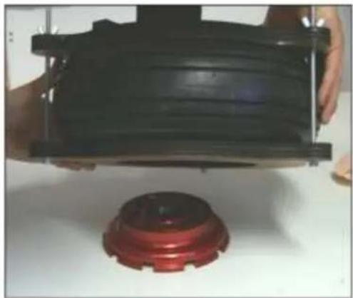
f) Insert the tire on the assembly with red spot in front of the valve
g) Place the second part of the plywood tool on the assembly and screw the 3 butterfly nuts. Press the tire till the conical bushing can be removed.

natural_image
Stacked red and silver cylindrical objects with reflective surfaces, placed on a wooden surface (no text or symbols visible)
natural_image
Close-up of a mechanical component with a circular top and black base, featuring a red liquid and a barcode tag (no readable text or symbols)| Nature du document :Installation and Maintenance Manual | Ref document:BRG-MM-002(A) |
 | Van'sRV3,RV4,RV6,RV6A,RV7,RV7A,RV8,RV8A,RV9,RV9A,RV10,RV12,RV14 and RV14A | Page64 / 73 |
h) Place the inner wheel flange on the table and position the large o-ring in the groove.
i) Return the plywood tool with assembly onto the inner wheel flange. Position the assembly so that bolt holes are aligned.
CAUTION: Care should be taken to ensure that the o-ring is in place
j) Put a drop of threadlocker at the end of each screw. Then insert the 8 screws and align the bolt holes so that no force is required to screw them.
k) Screw to contact with torque 2 to 4 N.m (17 to 35 in-lbs)
CAUTION: using a wrong threadlocker or not from recommended type may cause loose of screws or removal problem.
natural_image
Close-up of hands holding a black plastic component with a red circular base (no visible text or symbols)
natural_image
Product photo of a red LOCTITE 243 spray bottle with a close-up of metallic pins (no visible text or symbols on the product itself)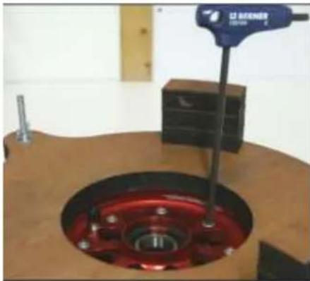
natural_image
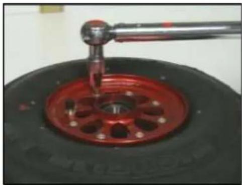
Close-up of a mechanical device with red liquid and a blue lever, no visible text or symbolsI) Then torque tighten with a torque wrench to 10 N.m (87 in-lbs)
NOTE: Respect the order when torque tightening
m) Torque tighten a second time each screw
CAUTION: Do not use impact or power wrenches
natural_image
Close-up of a red tire with a metal tool inserted, showing mechanical components (no text or symbols visible)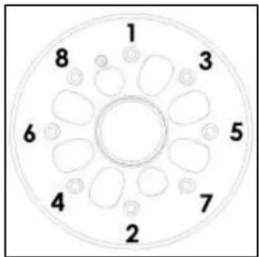

natural_image
Close-up of a pressure gauge measuring a tire with a red brake wheel (no visible text or symbols)n) Screw the valve core
o) Place the wheel in a protective enclosure and inflate to maximum tire rated pressure
p) Measure the inflation pressure 24h later and check that the pressure drop is not more than 10%.
CAUTION: If the pressure drop is higher than 10% it means there is a leakage, the wheel must be disassembled to check for eventual defect.
q) Then adjust the pressure to the one recommended by the aircraft manufacturer.
| Nature du document :Installation and Maintenance Manual | Ref document:BRG-MM-002(A) |
| Van'sRV3,RV4,RV6,RV6A,RV7,RV7A,RV8,RV8A,RV9,RV9A,RV10,RV12,RV14 and RV14A | Page65 / 73 |
7.7. Maintenance of wheel assembly
The maintenance consists in the inspection of the wheel parts and if required the replacement of next parts: - sealed ball bearings
- circlips
- assembly screws
- clips
NOTE: Maintenance can be performed by BERINGER service center.
7.7.1. Disassemble the wheel
- For disassemble the nose wheel see §7.2.3
- For disassemble the main wheel see §7.2.2
G. Remove circlips on wheel half with lock ring pliers
H. Disassembly of the wheel bearing
Place wheel ange in an oven at 110^ C ( 230^ F) to 120^ C ( 250^ F) for 30 minutes.
Remove wheel half from heat source and immediately remove bearing. If the bearing does not fall out by himself: tap it evenly with a ber dri pin or use a suitable arbor press.

CAUTION: Do not reuse a ball bearing that has already been mounted, even if in new condition.
I. Remove clips
For main Wheel only: remove screws and clips if they are out of tolerance.
CAUTION: Clip screws have been mounted with threadlocker: do not force while screwing out the small screws otherwise you may break the screw.
J. Cleaning
Clean all metal parts using water with soap or cleaning solvent and wipe dry with a clean cloth.
CAUTION: Do not use basic or acid agent on wheel halves. Anodizing can be totally removed within few minutes in contact with basic agent. Make sure that cleaning soap is not basic.
Apply air pressure to dry internal threads
CAUTION: Oily solvent or oily air pressure must not be used on internal thread because threadlocker will not properly lock the screws.
| Nature du document :Installation and Maintenance Manual | Ref document:BRG-MM-002(A) |
 | Van'sRV3,RV4,RV6,RV6A,RV7,RV7A,RV8,RV8A,RV9,RV9A,RV10,RV12,RV14 and RV14A | Page66 / 73 |
K. Inspection
Visually inspect wheel flanges for cracks, nicks, corrosion, or other damage.
Causes for replacement of wheel flanges:
➢ Signs of deep corrosion in critical areas
➢ Anodizing color removed on more than 15% of external surface
▶ Heavy nicks
➢ Deformed flanges
▶ Damaged bearing bore
CAUTION: Anodizing coating must not be painted.
Do not use sandpaper on any parts. Sandpaper will remove anodizing coating.
Visually inspect outer wheel half for scratches, nicks, corrosion, or other damage.
Causes for replacement of outer wheel half :
▶ Signs of deep corrosion in crical areas
➢ Anodizing color removed on more than 15% of external surface
▶ Heavy nicks
➢ Scratches on sealing surfaces in contact with o-ring

| Nature du document :Installation and Maintenance Manual | Ref document:BRG-MM-002(A) |
| Van'sRV3,RV4,RV6,RV6A,RV7,RV7A,RV8,RV8A,RV9,RV9A,RV10,RV12,RV14 and RV14A | Page67 / 73 |
7.7.2. Reassemble the wheel
A. Assembly of the wheel bearing
➢ Place wheel flange in an oven at 110°C (230°F) to 120°C (250°F) for 30 minutes, never exceed 150°C (300°F)
CAUTION: Do not attempt to install bearing without heating the wheel flange, it will damage bearing bore.
Use a new sealed ball bearing
CAUTION: Do not reuse a ball bearing that has already been mounted, even if in new condition.
CAUTION: Use only a ball bearing from BERINGER. There are many different qualities in ball bearings and most of them are not compliant with BERINGER requirements.
➢ Install the ball bearing into bearing bore of heated wheel flange using appropriate tool. Tap gently into place with a fiber drift making sure cup is evenly seated against shoulder of wheel half.
CAUTION: Do not use a hammer to press bearing, it will damage balls and cause failure of ball bearing

B. After cooling down period, install new circlips
C. Check that circlips are in place
CAUTION: Circlips maintain ball bearing, if circlips are not in place bearing can slide out and cause the blocking of the wheel.
D. If clips (drive keys) have been removed then install new clips and new screws
E. Put a drop of threadlocker high strength (Loctite 271 recommended) on each end of the clip screw
CAUTION: using a wrong threadlocker or not from recommended type may cause loose of screws or removal problem. Do not leave threadlocker more than few minutes on the screw.
F. Torque tighten to 1.5 N.m (13 in-lb) while pressing the clip onto the rim with a grip
G. Check that disc slides without effort in wheel slots.
NOTE: If disc cannot slide in the slots, remove concerning clip and install again.


natural_image
Sketch of a landscape with buildings and waterways (no text or symbols)Installation and Maintenance Manual
Ref document: BRG-MM-002(A)
| Van'sRV3,RV4,RV6,RV6A,RV7,RV7A,RV8,RV8A,RV9,RV9A,RV10,RV12,RV14 and RV14A | Page68 / 73 |
| Nature du document :Installation and Maintenance Manual | Ref document:BRG-MM-002(A) |
| Van'sRV3,RV4,RV6,RV6A,RV7,RV7A,RV8,RV8A,RV9,RV9A,RV10,RV12,RV14 and RV14A | Page69 / 73 |
7.8. Brake Assembly
7.8.1. Disassembly – Reassembly – Brake Pads change
ON AIRCRAFT PADS CHANGE:
a) Remove wheel fairings and lift up the aircraft so that the wheels can be removed from the axle.
CAUTION: Respect the procedures of the aircraft manufacturer
WARNING: Insure aircraft is secure and stable before beginning any work. Working under an improperly stabilized aircraft could cause injury or death
b) Remove the cotter pin and the axle nut. Cut and remove the safety wire
c) Pull off the wheel with hands


d) Remove the 3 caliper assembly screws or only one screw on the side
NOTE: Do not remove the caliper back plate from the axle Do not disconnect the hydraulic fitting
CAUTION: While the caliper housing is separated do not apply brake pressure
e) Remove the old brake pads
NOTE: The disc has not to be removed during the pad change It is recommended to leave the disc in place
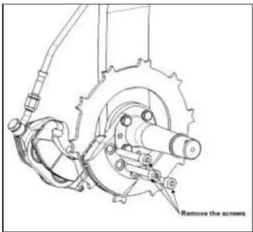

| Nature du document :Installation and Maintenance Manual | Ref document:BRG-MM-002(A) |
 | Van'sRV3,RV4,RV6,RV6A,RV7,RV7A,RV8,RV8A,RV9,RV9A,RV10,RV12,RV14 and RV14A | Page70 / 73 |
f) Clean all around pistons with a dry cloth to remove dust
CAUTION: Do not use solvent of any type to clean caliper housing and pistons. Solvent will penetrate to piston seals and may damage them. Use only a dry cloth.
g) Push back the pistons with fingers
CAUTION: If pushing back with hands is too hard then pistons and seals are sticking or may be blocked for other reason. Maintenance is required with change of seals and eventual change of other parts.
h) Insert new pads
CAUTION: Never mix old and new pads. All 4 pads (2 left and 2 right) must be replaced at the same time


NOTE: Pad insulator and grid should not be reused, they come together with new brake pads
i) Put a drop of threadlocker medium strength (Loctite 243 recommended) on each end of the assembly screw.
CAUTION: using a wrong threadlocker or not from recommended type may cause loose of screws or removal problem.
| Nature du document :Installation and Maintenance Manual | Ref document:BRG-MM-002(A) |
 | Van'sRV3,RV4,RV6,RV6A,RV7,RV7A,RV8,RV8A,RV9,RV9A,RV10,RV12,RV14 and RV14A | Page71 / 73 |
j) Screw to contact and torque tighten to 25 N.m (220 in-lb)
k) torque all screws a second time to 25 N.m (220 in-lb)
CAUTION: Check that brake pads can slide without effort

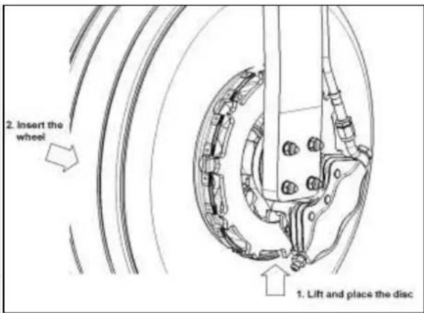
I) Insert the wheel on the axle while placing the disc in wheel slots
m) Screw the axle nut to the required torque
n) Secure the axle nut with a cotter pin
o) Place a new safety wire (stainless steel 1mm - 0.040")
p) Apply brake pressure 5-10 times and check brake fluid level in the reservoir
q) Check the brake efficiency and also the residual drag on the wheel
CAUTION: When the brakes are released you must be able to turn the wheel easily by hand.


When new brake pads have been installed, it is important to condition them properly. Rated brake torque value is reached only after a full conditioning of brake pads and disc.
CAUTION: Brake torque value can be only 50% of rated brake torque before the conditioning. It means that even with full brake effort the aircraft will not stop as usual. Pilot must take into consideration this parameter to avoid loose of aircraft control during the conditioning procedure.
| Nature du document :Installation and Maintenance Manual | Ref document:BRG-MM-002(A) |
| Van'sRV3,RV4,RV6,RV6A,RV7,RV7A,RV8,RV8A,RV9,RV9A,RV10,RV12,RV14 and RV14A | Page72 / 73 |
8. TROUBLESHOOTING
This paragraph provides information necessary to identify, diagnose and correct potential problems which may occur with the wheel or brake assemblies.
| TROUBLE | PROBABLE CAUSE | CORRECTION |
| 1.Brakes won't hold | Improper conditioning of brake pads and disc | See the conditioning procedure §2 |
| Brake fluid or grease on disc and pads | Clean the disc and change the pads | |
| Wrong brake fluid has caused blocking of pistons | Change all seals of the system, put the right fluid | |
| Pads worn below minimum wear limits | Change brake pads | |
| Insufficient hydraulic pressureImproper master cylinder bore | Check the master cylinder type and geometry | |
| 2.Excessive toe pedal travel, spongy pedal or lever | Air in hydraulic system | Bleed the hydraulic system |
| Leak in the system | Locate leak and repair | |
| Improper brake lines, too expandable | Replace brake lines | |
| Caliper assembly bolts are not tighten | Torque bolts to proper value | |
| Improper adjustment of master cylinder: does not release completely | Modify the pedal geometry or length of master cylinder | |
| Defective seal in master cylinder | Replace | |
| 3.Brake drag | Residual brake pressure due to improper adjustment of master cylinder: does not release completely | Modify the pedal geometry or length of master cylinder |
| Residual brake pressure due to excessive pressure in the reservoir | Open and close the reservoir to release the pressure | |
| Wrong brake fluid has caused blocking of pistons | Change all seals of the system, put the right fluid | |
| Improper brake assembly fixing | Inspect and repair | |
| Pistons do not retract | Inspect for damage, change seals and pistons | |
| Pads are blocked and do not release | Inspect and repair | |
| 4.Rapid disc and pads wear | Improper conditioning of pads and disc | See the conditioning procedure §2 |
| Frequent overheating of disc and pads, brake is not adapted to the use | Replace brake assembly by another model with increased energy capacity |
| Nature du document :Installation and Maintenance Manual | Ref document:BRG-MM-002(A) |
| Van'sRV3,RV4,RV6,RV6A,RV7,RV7A,RV8,RV8A,RV9,RV9A,RV10,RV12,RV14 and RV14A | Page73 / 73 |
| Excessive rusting, scoring or pitting of brake disc | Repair or replace the disc and pads | |
| 5.Cracked or distorted wheel flanges | Improper tire inflation pressure | Replace wheel flange, check tire inflation pressure |
| Loads applied excess the wheel load ratings | Change wheel model for a stronger one | |
| 6.Rapid decrease of tire pressure (10 PSI per day) | Improper tire mounting, damaged seal | Disassemble and replace seals |
| Leak at valve core | Replace valve core | |
| 7.Medium decrease of tire pressure (10 PSI per week) | Improper tire | Use only tubeless tires |
| Scratches on sealing faces | Replace the part by a new one | |
| Defective valve core | Replace valve core | |
| 8.Slow decrease of tire pressure (10 PSI per month) | Standard decrease of pressure with some tubeless tires | Inflate tire to the appropriate pressure. Check inflation pressure every month. |
| Nature du document :Installation and Maintenance Manual | Ref document:BRG-MM-002(A) |
- Installation and Maintenance Manual Van's RV3,4,6,6A,7,7A,8,8A,9,9A,10,12,14 and 14A
- SOMMAIRE
- FUSELAGE KIT VANS RV6,RV6A,RV7,RV7A,RV9,RV9A,RV10 AND RV14.... 32
- BRAKE LINE 45
- MAINTENANCE 47
- TROUBLESHOOTING....72
- General
- Nose wheel Kit
- RV6A, RV7A, RV8A and RV9A
- Finishing Kit for main wheels
- RV3
- Installation Main wheel Assy Right and left (Drawing reference: AV-VANS-320R)
- RV4, RV6, RV6A, RV7, RV7A, RV8A, RV9 and RV9A
- Main wheel Assy Left (Drawing reference: AV-VANS-620L)
- Installation Main wheel Assy Right and left (Drawing reference: AV-VANS-620R)
- RV8 Grove Landing Gear
- Main wheel Assy Right (Drawing reference: AV-VANS-420R)
- Installation Main wheel Assy Right and left (Drawing reference: AV-VANS-420L)
- RV10
- Main wheel Assy Right (Drawing reference: AV-VANS-520R)
- Installation Main wheel Assy Right and left (Drawing reference: AV-VANS-520L)
- RV14
- Main wheel Assy Right (Drawing reference: AV-VANS-220R)
- Installation Main wheel Assy Left and right
- Fuselage Kit
- Fuselage Kit VANS RV6,RV6A,RV7,RV7A,RV9,RV9A,RV10 and RV14.
- Brake line
- Hose 01 (Main wheel / Fuselage)
- Hose 02 (Fuselage/FP)
- Hose 03 (FP/Regulator)
- Hose 04 (Regulator/MC Pilot)
- Hose 05 (MC Pilot/MC Copilot)
- Hose 06 (MC Copilot-Reservoir)
- Hose 07 (MC pilot-FP)
- Hose 08 (Fuselage -MC pilot)
- Assembly Master cylinder right and left (Drawing reference AV-VANS-560)
- Assembly Brake reservoir (Drawing reference AV-VANS-570)
- Assembly Parking brake valve(Drawing reference AV-VANS-590)
- Brake line
- Maintenance
- Equipment concerned
- Quick Reference Specifications
- Main Wheels:
- 6.00-6 Main wheel assembly RF-016(A):
- Nose Wheels:
- Brake caliper:
- Description
- Cleaning
- Conditioning Procedure for Brake Pads
- CONDITIONNING PROCEDURE:
- Scheduled maintenance checks
- Safety maintenance checks
- Safety wire
- Brake disc
- NOTE:
- Airworthiness Limitations
- a) GENERAL:
- b) LIFE LIMITED PARTS:
- Disassembly – Reassembly – Tire change
- Disassembly:
- CLEANING:
- Reassembly:
- CAUTION: Care should be taken to ensure that the o-ring is in place
- CAUTION: using a wrong threadlocker or not from recommended type may cause loose of screws or removal problem.
- NOTE: Respect the order when torque tightening
- CAUTION: If the pressure drop is higher than 10% it means there is a leakage, the wheel must be disassembled to check for eventual defect.
- Maintenance of wheel assembly
- Disassemble the wheel
- Inspection
- CAUTION: Anodizing coating must not be painted.
- Reassemble the wheel
- Brake Assembly
- TROUBLESHOOTING
Brand : Beringer
Model : SRVFU01
Category : Light aircraft