
3231L - Blender DBX - Free user manual and instructions
Find the device manual for free 3231L DBX in PDF.


| Product Type | Graphic Equalizer |
| Brand | DBX |
| Model | 3231L |
| Frequency Bands | 31 ISO standard 1/3 octave bands from 20 Hz to 20 kHz |
| Boost/Cut Range | ±6 dB or ±12 dB (selectable) |
| Input Impedance | 75 kΩ balanced, 50 kΩ unbalanced |
| Output Impedance | 100 Ω balanced, 50 Ω unbalanced |
| Maximum Input Level | +22 dBu |
| Common Mode Rejection Ratio (CMRR) | >85 dB at 1 kHz |
| Frequency Response | 20 Hz to 20 kHz, ±1 dB (all faders flat) |
| THD+Noise | <0.004% at 1 kHz, +4 dBu input |
| Dynamic Range | 112 dB |
| Noise | < -90 dBu @ ±6 dB range (faders flat) |
| High Cut Filter | 12 dB/octave at 15 kHz |
| Low Cut Filter | 12 dB/octave, variable from 25 Hz to 200 Hz |
| Headroom Meter | 8 LED segments, 3 to 42 dB |
| Input Connectors | XLR (female), 1/4" TRS, barrier strip |
| Output Connectors | XLR (male), 1/4" TRS, barrier strip |
| Power Requirements | 100, 120, 230, 240 VAC, 50/60 Hz, 30 W |
| Dimensions (H x W x D) | 5.25" x 19" x 7.9" (13.33 cm x 48.25 cm x 20.06 cm) |
| Weight | 12 lbs (5.44 kg) |
| Chassis Ground Lift | Removable strap on rear panel |
| Bypass System | Active bypass (EQ IN/OUT) and passive relay bypass on power-down |
| Construction | Toroidal power supply, steel chassis, rack-mountable |
Frequently Asked Questions - 3231L DBX
User questions about 3231L DBX
0 question about this device. Answer the ones you know or ask your own.
Ask a new question about this device
Download the instructions for your Blender in PDF format for free! Find your manual 3231L - DBX and take your electronic device back in hand. On this page are published all the documents necessary for the use of your device. 3231L by DBX.
USER MANUAL 3231L DBX
WARNING: TO REDUCE THE RISK OF FIRE OR ELECTRIC SHOCK, DO NOT EXPOSE THIS EQUIPMENT TO RAIN OR MOISTURE.
CAUTION: TO REDUCE THE RISK OF FIRE OR ELECTRICAL SHOCK, DO NOT REMOVE COVER (OR BACK). NO USER SERVICABLE PARTS INSIDE. REFER SERVICING TO QUALIFIED SERVICE PERSONNEL.

This symbol, where ever it appears, alerts you to the presence of uninsulated dangerous voltage inside the enclosure - voltage that may be sufficient to constitute a risk of shock.

This symbol, wherever it appears, alerts you to important operating and maintenance instructions in the accompanying literature. Read the manual.
All trademarks are property of their respective companies.
This manual is part number 18-0521-A
© Copyright 1995 by dbx Professional Products

dbx Professional Products 8760 South Sandy Parkway Sandy, Utah 84070 Telephone (801) 568-7660 FAX (801) 568-7662
MANUAL CONTENTS
INTRODUCTION 2
QUICK SET-UP 2
INSPECTION 3
WARRANTY 3
Congratulations for your purchase of a dbx equalization component. The dbx Graphic Equalizers are high performance multifunctional units designed to deliver all the flexibility and power that professional users demand. We recommend you take a moment to read through this Operation Manual. It provides information that will assist you from system set-up to EQ applications. The 30 Series features include:
☐ 31 ISO standard center 1/3 octave constant Q frequency bands per channel (or 15 ISO standard center 2/3 octave constant Q frequency bands per channel on model 3215)
○ Low phase shift circuit design
○ Variable high pass and switchable low pass 12dB/octave filters
○ Electronically balanced inputs with superior common mode rejection
○ Servo balanced outputs
○ XLR, barrier strip, and TRS connectors
○ -12dB/+15dB of input gain
○ Chassis ground lift capability
○ Toroidal power supply transformer
○ Relay bypass on power-down
QUICK SET-UP
To get the equalizer up and running as quickly as possible, do the following:
○ Unpack and inspect the equalizer and contents (pg. 3).
○ Connect the equalizer to the system (pg. 6).
○ Set levels and controls as needed (pg. 4).
For more detailed information about these steps, refer to the specified pages.
INSPECTION
Verify that the equalizer's package contains the following:
○ Equalizer Unit (according to Model number marked on package)
○ AC Power Cord
○ Operation Manual
○ Registration Card
○ 4 Rack Mount Screws and Washers
If any of these items are missing, please contact dbx customer service at the number provided on the inside cover.
WARRANTY
This warranty is valid only for the original purchaser and only in the United States. We warrant dbx products against defects in material or workmanship for a period of two years from the date of original purchase for use, and agree to repair or, at our option, replace any defective item, except external power transformers, without charge for either parts or labor.

IMPORTANT: This warranty does not cover damage resulting from accident, misuse or abuse, lack of reasonable care, the affixing of any attachment not provided with the product, loss of parts, or connecting the product to any but the specified receptacles. This warranty is void unless service or repairs are performed by an authorized service center. No responsibility is assumed for any special, incidental or consequential damages. However, the limitation of any right or remedy shall not be effective where such is prohibited or restricted by law.
Simply take or ship your dbx product prepaid to our service department. Be sure to include your sales slip as proof of purchase date. (We will not repair transit damage under the no-charge terms of this warranty.) dbx will pay return shipping.
NOTE: No other warranty, written or oral is authorized for dbx products.
This warranty gives you specific legal rights, and you may also have other rights which vary from state to state. Some states do not allow the exclusion of limitations of incidental or consequential damages or limitations on how long an implied warranty lasts, so the above exclusion and limitations may not apply to you.
OPERATING CONTROLS
dbx 3031

dbx 3031C

dbx 3231L

dbx 3215

POWER SWITCH: Turns the equalizer's power ON or OFF. Power ON is indicated by the lighted power LED.
POWER LED: Lights to indicate that the equalizer is turned on.
EQ IN/OUT: This switch removes the equalizer's input gain and individual slider controls from the signal path. This does not, however, affect the HI CUT and LOW CUT filters. The entire equalizer is enabled when the switch is in.
BOOST/CUT RANGE SELECTION SWITCH: The switch selects which of the two boost/cut ranges the equalizer will use, either ±6dB or ±12dB (3031C: -10dB or -20dB)
HEADROOM BAR GRAPH: The eight LED's indicate peak levels within the equalizer. The top LED is 3dB below clipping and indicates overload at the post-input gain, pre-EQ and post-EQ points in the signal path.. Overload at the input amplifier is indicated by the entire LED bar graph getting brighter when the signal is 3dB below clipping.
INPUT GAIN CONTROL: This control sets the signal level to the equalizer. It is capable of -12dB to +15dB of gain. Its effect is indicated on the HEADROOM BAR GRAPH.
FREQUENCY BAND SLIDER CONTROL: Each one of these slider potentiometers will boost or cut its noted frequency by ±6 dB or ±12dB depending upon the position of the BOOST/CUT RANGE SWITCH (3031C is cut only: -10db or -20db). When all of the sliders are in the center detented position, the output of the equalizer is flat (3031C: sliders placed at top position is flat). The frequency band centers of the 3215 are marked at 2/3rds of an octave ISO spacings. The frequency band centers of the 3031,3031C, and 3231 are marked at 1/3rd of an octave ISO spacing.
LO CUT FREQUENCY CONTROL AND LO CUT IN/OUT SWITCH: This control varies the cutoff frequency of the LO-CUT filter. It is variable from 25 Hz to 200 Hz. The roll-off of this filter is 12dB per octave. The LO CUT IN/OUT switch to the left of this control inserts or removes the LO CUT filter from the signal path. When the LO CUT IN/OUT switch is pushed IN, the LO CUT filter is IN the circuit.
HI CUT IN/OUT SWITCH: This switch inserts or removes the HI-CUT filter from the signal path. When the HI-CUT IN/OUT switch is pushed IN, the HI-CUT filter is IN in the circuit.
CONNECTING THE EQ TO THE SYSTEM
The 30 Series equalizers have balanced inputs and outputs that can be used with any line-level device. For more specific information about cabling possibilities, please refer to INSTALLATION CONSIDERATIONS (pg. 9).
To connect the equalizer to the system, refer to the following steps:

○ Turn off all equipment before making any connections.
○ Mount equalizer in rack mount.
Install the EQs in a rack with the rack screws provided. It can be mounted above or below anything that does not generate excessive heat. Ambient temperatures should not exceed 113^ F ( 45^ C) when equipment is in use. Although the units chassis are shielded against radio frequency and electromagnetic interference, extremely high fields of RF and EMI should also be avoided.
○ Make audio connections via XLR, barrier strip or TRS jacks (according to application needs)
All three types of connectors for the inputs and outputs can be used for balanced or unbalanced connections. The use of more than one connector at a time for the input/output pair could unbalance balanced lines, cause phase cancellation, short a conductor to ground, or cause damage to the other equipment connected to the equalizer.
○ Select the operating range with the BOOST/CUT RANGE SELECTION SWITCH
○ Apply power to the equalizer
Connect the the AC power cord to the AC power receptacle on the back of the equalizer. Route the A.C. power cord to a convenient power outlet away from audio lines. The unit may be turned on and off from the front panel power switch or a master equipment power switch. Since they draw a relatively small amount of current during idle, the units may be left on continuously.
REAR PANEL DESCRIPTIONS
dbx 3031

dbx 3031C

dbx 3231L

dbx 3215
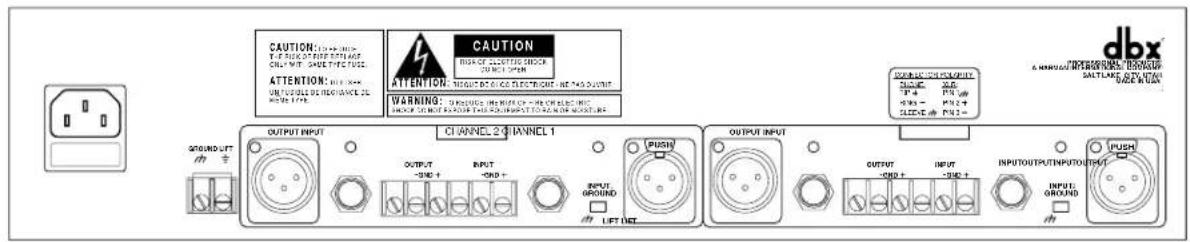
POWER CORD RECEPTACLE: Connects A.C. power to the equalizer.
INPUT CONNECTORS: Three types of input connectors are provided for input connections: female locking XLR type connectors, 1/4-inch tip-ring-sleeve phone jack connectors, and a barrier strip. The maximum input level that the equalizer can accept is +22dBu (ref: 0.775Vms).
OUTPUT CONNECTORS: Three types of output connectors are provided for output connections: male XLR type connectors, 1/4 inch tip-ring-sleeve phone jack connectors and a barrier strip.
INPUT GROUND LIFT SWITCH: Disconnects the grounding of the input connector from the equalizer's grounding system. This is sometimes helpful in preventing electronic "hum" in a sound system by breaking the common ground connection between the equalizer and other products.
CHASSIS GROUND LIFT STRAP: By removing the jumper connecting the two screws on the barrier strip, the chassis ground is separated from the electronic ground of the equalizer. This is sometimes necessary to prevent "ground loops" in a sound system.

FUSE: Should the fuse fail, be sure to determine and remove the cause of the problem before replacing the fuse. Failure to do so could result in damage to the equalizer. The following is a list of fuse types used for different AC voltage configurations:
100VAC T 250mA 250V
120VAC 200mA 250V Slow Blow
230VAC T 125mA 250V
240VAC T 125mA 250V
INSTALLATION CONSIDERATIONS
HOOKUPS AND CABLING: The 30 Series equalizers are designed for nominal +4dBu levels. The equalizers can be used with either balanced or unbalanced sources and the outputs can be used with either balanced or unbalanced loads, provided the proper cabling is used.
A balanced line is defined as two-conductor shielded cable with the two center conductors carrying the same signal but of opposite polarity when referenced to ground. An unbalanced line is generally a single-conductor shielded cable with the center conductor carrying the signal and the shield at ground potential.
INPUT CABLE CONFIGURATIONS: The equalizer has an input impedance of 75kΩ balanced and 50kΩ unbalanced. This makes the 30 Series equalizers audio inputs suitable for use with virtually any source impedance, low or high.
Note that XLR pins 2 and 3 are reversed on some products that you may be using with the equalizer.
OUTPUT CABLE CONFIGURATIONS: The equalizer's output is capable of driving a 600Ω load to +21dBu. For maximum hum rejection with a balanced source, avoid common grounding at the equalizer's inputs and outputs. Most balanced (3-conductor) cables have the shield connected at both ends. This can result in ground loops which cause hum.
If hum is a problem, try changing the position of the rear panel GROUND LIFT switch so that the ground is lifted. If hum persists try disconnecting the shield on one or more of the other cables in the system, preferably at the input of a device, not at the output.
The chassis ground or “earth” ground may be separated from the circuit ground by removing the CHASSIS GROUND LIFT STRAP on the back panel of the equalizer. This may also prevent ground loops in the sound system.
NORMAL BALANCED CONNECTIONS FOR INPUTS AND OUTPUTS
Connection XLR TRS 1/4" Jack Barrier strip ____
Ground: Pin 1 Sleeve Ground
High: Pin 2 Tip (+)
Low: Pin 3 Ring (-)
NORMAL UNBALANCED CONNECTIONS FOR INPUTS AND OUTPUTS
Connection XLR TRS 1/4" Jack TS 1/4" Jack Barrier strip ____
Ground: Pin 1 Sleeve Sleeve Ground
High: Pin 2 Tip Tip (+)
Low (ground): Pin 3 Ring Sleeve (-)
Tie pin 3 to the ground for unity gain in/out of the equalizer when using unbalanced input connections to balanced output connections or balanced input connections to unbalanced output connections. To do otherwise won't hurt the unit but will result in unmatched input to output levels, and the level control will not be properly calibrated.

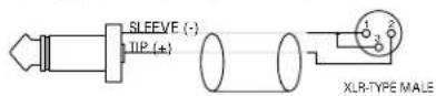
The following cable wiring diagrams may to assist you with input and output connections for both balanced and unbalanced connectors.
FROM SOURCE DEVICE TO NEXT DEVICE

FROM SOURCE DEVICE

FEMALE XLR-TYPE TO STEREO PHONE PLUG STEREO PHONE PLUG TO MALE XLR-TYPE
FROM SOURCE DEVICE TO NEXT DEVICE

TO NEXT DEVICE FROM SOURCE DEVICE

STEREO PHONE PLUG TO STEREO PHONE PLUG FEMALE XLR-TYPE TO MALE XLR-TYPE
FROM SOURCE DEVICE TO NEXT DEVICE
TO NEXT DEVICE FROM SOURCE DEVICE

MONO PHONE PLUG TO MALE XLR-TYPE MONO PHONE PLUG TO STEREO PHONE PLUG
FROM SOURCE DEVICE TO NEXT DEVICE

TO NEXT DEVICE FROM SOURCE DEVICE

PHONO PLUG TO STEREO PHONE PLUG
RCA PHONO PLUG TO MALE XLR-TYPE
FROM SOURCE DEVICE TO NEXT DEVICE

TO NEXT DEVICE FROM SOURCE DEVICE

MONO PHONE PLUG TO MONO PHONE PLUG PHONO PLUG TO MONO PHONE PLUG
FROM SOURCE DEVICE TO NEXT DEVICE

STEREO PHONE PLUG TO MONO PHONE PLUG
TO NEXT DEVICE FROM SOURCE DEVICE

MONO PHONE PLUG TO PHONO PLUG
FROM SOURCE DEVICE TO NEXT DEVICE

PHONO PLUG TO MALE XLR-TYPE
OTHER CONSIDERATIONS: It is useful to keep in mind the active and passive bypass systems in these equalizers. When the power is ON the EQ IN/OUT switch (active bypass) removes the equalizer from the signal path except for buffer amplifiers, HI CUT and LO CUT filters. Should the power to the unit fail or the power be turned off, the passive bypass completely removes the equalizer from the signal path allowing the signal to pass through the equalizer completely unaffected.
There is an optional Input and/or Output Transformer kit available for the 30 Series equalizers which may be installed for special applications. Contact your dealer or contractor for more information regarding this product.
OPERATION AND APPLICATION NOTES
The dbx graphic equalizers are useful audio signal processing tools in situations where precise frequency control is required across the audible frequency spectrum.
When used with an audio spectrum analyzer the EQs can tune any acoustical environment - from the studio to the concert hall- to stop ringing, increase clarity, and flatten the overall frequency response of the environment. A real time audio spectrum analyzer or other types of audio environment analyzers are very useful in determining the amount of equalization needed.
Insert the graphic equalizer between the signal source (usually a mixer) and the power amplifiers to the speakers (or the crossover if there is one). Adjust the level and equalization as required to yield the desired system response. The long throw sliders of the EQs allow very precise settings of the equalization for accurate equalization curves.

flowchart
graph TD
    A["MIXING CONSOLE"] --> B["EQUALIZER"]
    A --> C["CROSS-OVER (OPTIONAL)"]
    B --> D["MIXER OUTPUT"]
    C --> E["OUTPUT INPUT"]
    C --> F["TO AMP OUTPUT INPUT"]
A very similar set-up is used for portable sound reinforcement systems. The EQs are especially useful to eliminate feedback from stage rumble, poorly placed microphones, or wind noise, notching out the offending frequencies. Stage rumble is easily taken care of with LOW CUT filter control. The equalizer can also help to make up for some sound system deficiencies in frequency response.
In the studio, the EQs are very useful in modifying and enhancing audio signals. Route the signal to the equalizer and then return it to the mixing board after modification to be mixed with other signals or processed further. Comparison of the equalized signal with the unprocessed signal is performed with the IN/OUT switch.

flowchart
graph TD
    A["MIXING CONSOLE"] --> B["SENDRETURN"]
    A --> C["EQUALIZER"]
    C --> D["OUTPUTINPUT"]
TECHNICAL SUPPORT / FACTORY SERVICE
The dbx EQs are all-solid-state product with components chosen for high performance and excellent reliability. Each has been tested and burned in at the factory. No adjustment of any type should be required throughout the life of the unit.
If circumstances arise which necessitate repair, we recommend that your EQ be returned to the factory. This can only be done by receiving an Return Authorization number from dbx customer service.
If you require technical support, contact dbx customer service. Be prepared to accurately describe the problem. Know the serial number of your unit (printed on a sticker attached to the real panel).
dbx Professional Products
8760 South Sandy Parkway
Sandy, Utah 84070 USA
Phone: (801)568-7660
Fax: (801)568-7662
Int'l Fax: (603)672-4346
SPECIFICATIONS
3031:
INPUT Electronically Balanced XLR(pin 2 hot), barrier strip, 1/4" Jack (tip hot)
IMPEDANCE 75kΩ balanced, 50kΩ unbalanced
MAX LEVEL +22 dBu (ref: 0.775Vms)
CMRR >85dB at 1kHz
OUTPUT Servo Balanced XLR(pin 2 hot), barrier strip, 1/4" Jack (tip hot)
IMPEDANCE 100Ω balanced, 50Ω unbalanced
MAX LEVEL +22 dBu (ref: 0.775Vms)
NOISE < -90dBu @ ±6dB boost/cut range (faders flat, test bandwidth 22 Hz to 22kHz)
FREQ RESPONSE 20Hz to 20kHz, ±1dB (all faders flat)
THD+NOISE < .004% (at 1kHz, +4 dBu input, test bandwidth 22 Hz to 22kHz)
DYNAMIC RANGE 112dB
CONTROL RANGE ±6 dB or ±12dB cut/boost
31 ISO Standard, 1/3 octave bands per channel from 20Hz to 20kHz:
20, 25, 31.5, 40, 50, 63, 80, 100, 125, 160, 200, 250, 315, 400, 500,
630, 800, 1k, 1.25k, 1.6k, 2k, 2.5k, 3.15k, 4k, 5k, 6.3k, 8k, 10k, 12.5k, 16k, and 20k.
Hi-CUT FILTER 12dB/octave, 15kHz
Low-CUT FILTER 12dB per octave, variable from 25Hz to 200Hz
HEADROOM METER 3 to 42 dB, 8 LED segments
POWER REQUIREMENTS 100, 120, 230, 240 VAC 50/60 Hz, 30 watts
WEIGHT 8.5lbs (3.85 kg)
DIMENSIONS 7.9" x 3.5" x 19" (20.06 cm x 8.88 cm x 48.25 cm)
3031C:
| INPUT | Electronically Balanced XLR(pin 2 hot), barrier strip, 1/4" Jack (tip hot) |
| IMPEDANCE 75kΩ balanced, 50kΩ unbalanced | |
| MAX LEVEL +22 dBu (ref: 0.775Vms) | |
| CMRR >85dB at 1kHz | |
| OUTPUT | Servo Balanced XLR(pin 2 hot), barrier strip, 1/4" Jack (tip hot) |
| IMPEDANCE 100Ω balanced, 50Ω unbalanced | |
| MAX LEVEL +22 dBu (ref: 0.775Vms) | |
| NOISE < -90dBu @ -10dB boost/cut range (faders flat, test bandwidth 22 Hz to 22kHz) | |
| FREQ RESPONSE 20Hz to 20kHz, ±1dB (all faders flat) | |
| THD+NOISE < .004% (at 1kHz, +4 dBu input, test bandwidth 22 Hz to 22kHz) | |
DYNAMIC RANGE 112dB
CONTROL RANGE -10 dB or -20dB cut
31 ISO Standard, 1/3 octave bands per channel from 20Hz to 20kHz: 20, 25, 31.5, 40, 50, 63, 80, 100, 125, 160, 200, 250, 315, 400, 500, 630, 800, 1k, 1.25k, 1.6k, 2k, 2.5k, 3.15k, 4k, 5k, 6.3k, 8k, 10k, 12.5k, 16k, and 20k.
Hi-Cut FILTER 12dB/octave, 15kHz
Low-CUT FILTER 12dB per octave, variable from 25Hz to 200Hz
HEADROOM METER 3 to 42 dB, 8 LED segments
POWER REQUIREMENTS 100, 120, 230, 240 VAC 50/60 Hz, 30 watts
WEIGHT 8.5lbs (3.85 kg)
DIMENSIONS 7.9" x 3.5" x 19" (20.06 cm x 8.88 cm x 48.25 cm)
3231L:
INPUTS Electronically Balanced XLR(pin 2 hot), barrier strip, 1/4" Jack (tip hot) IMPEDANCE 75kΩ balanced, 50kΩ unbalanced MAX LEVEL +22 dBu (ref: 0.775Vms) CMRR >85dB at 1kHz
OUTPUTS Servo Balanced XLR(pin 2 hot), barrier strip, 1/4" Jack (tip hot) IMPEDANCE 100Ω balanced, 50Ω unbalanced MAX LEVEL +22 dBu (ref: 0.775Vms) NOISE < -90dBu @ ±6dB boost/cut range (faders flat, test bandwidth 22 Hz to 22kHz) FREQ RESPONSE 20Hz to 20kHz, ±1dB (all faders flat) THD+NOISE < .004% (at 1kHz, +4 dBu input, test bandwidth 22 Hz to 22kHz)
DYNAMIC RANGE 112dB
CONTROL RANGE ±6 dB or ±12dB cut/boost 31 ISO Standard, 1/3 octave bands per channel from 20Hz to 20kHz: 20, 25, 31.5, 40, 50, 63, 80, 100, 125, 160, 200, 250, 315, 400, 500, 630, 800, 1k, 1.25k, 1.6k, 2k, 2.5k, 3.15k, 4k, 5k, 6.3k, 8k, 10k, 12.5k, 16k, and 20k.
Hi-Cut FILTER 12dB/octave, 15kHz
Low-CUT FILTER 12dB per octave, variable from 25Hz to 200Hz
HEADROOM METER 3 to 42 dB, 8 LED segments
POWER REQUIREMENTS 100, 120, 230, 240 VAC 50/60 Hz, 30 watts
WEIGHT 12 lbs (5.44 kg)
DIMENSIONS 7.9" x 5.25" x 19" (20.06 cm x 13.33 cm x 48.25 cm)
3215:
| INPUTS | Electronically Balanced XLR(pin 2 hot), barrier strip, 1/4" Jack (tip hot) |
| IMPEDANCE 75kΩ balanced, 50kΩ unbalanced | |
| MAX LEVEL +22 dBu (ref: 0.775Vms) | |
| CMRR >85dB at 1kHz | |
| OUTPUTS | Servo Balanced XLR(pin 2 hot), barrier strip, 1/4" Jack (tip hot) |
| IMPEDANCE 100Ω balanced, 50Ω unbalanced | |
| MAX LEVEL +22 dBu (ref: 0.775Vms) | |
| NOISE < -90dBu @ ±6dB boost/cut range (faders flat, test bandwidth 22 Hz to 22kHz) | |
| FREQ RESPONSE 20Hz to 20kHz, ±1dB (all faders flat) | |
| THD+NOISE < .004% (at 1kHz, +4 dBu input, test bandwidth 22 Hz to 22kHz) | |
DYNAMIC RANGE 112dB
CONTROL RANGE ±6 dB or ±12dB cut/boost 15 ISO Standard, 2/3 octave bands per channel from 25Hz to 16kHz: 25, 40, 63, 100, 160, 250, 400, 630, 1k, 1.6k, 2.5k, 4k, 6.3k, 10k, and 16k.
Hi-CUT FILTER 12dB/octave, 15kHz
Low-CUT FILTER 12dB per octave, variable from 25Hz to 200Hz
HEADROOM METER 3 to 42 dB, 8 LED segments
POWER REQUIREMENTS 100, 120, 230, 240 VAC 50/60 Hz, 30 watts
WEIGHT 9lbs (4.08 kg)
DIMENSIONS 7.9" x 3.5" x 19" (20.06 cm x 8.88 cm x 48.25 cm)


- MANUAL CONTENTS
- QUICK SET-UP
- INSPECTION
- WARRANTY
- OPERATING CONTROLS
- CONNECTING THE EQ TO THE SYSTEM
- REAR PANEL DESCRIPTIONS
- INSTALLATION CONSIDERATIONS
- NORMAL BALANCED CONNECTIONS FOR INPUTS AND OUTPUTS
- NORMAL UNBALANCED CONNECTIONS FOR INPUTS AND OUTPUTS
- OPERATION AND APPLICATION NOTES
- TECHNICAL SUPPORT / FACTORY SERVICE
- SPECIFICATIONS
- 3031:
- DYNAMIC RANGE 112dB
- 3231L:
Brand : DBX
Model : 3231L
Category : Blender