
AUC27F - Freezer Arctic Air - Free user manual and instructions
Find the device manual for free AUC27F Arctic Air in PDF.


| Product Type | Freezer |
| Brand | Arctic Air |
| Model | AUC27F |
| Dimensions (H x W x D) | 85 cm x 70 cm x 70 cm |
| Weight | 40 kg |
| Energy Class | A+ |
| Annual Energy Consumption | 250 kWh |
| Noise Level | 42 dB |
| Net Capacity | 270 L |
| Temperature Range | -18 °C to -24 °C |
| Defrost Type | Manual |
| Interior Light | No |
| Lock | Yes |
| High Temperature Alarm | Yes |
| Refrigerant Type | R600a |
| Climatic Class | N/ST |
| Installation Type | Freestanding |
| Door Hinge | Left or right (reversible) |
| Cooling System | Static (fan-assisted optional) |
| Freezing Capacity | 10 kg/24h |
| Storage Time During Power Failure | 12 hours |
| Warranty | 2 years |
Frequently Asked Questions - AUC27F Arctic Air
User questions about AUC27F Arctic Air
0 question about this device. Answer the ones you know or ask your own.
Ask a new question about this device
Download the instructions for your Freezer in PDF format for free! Find your manual AUC27F - Arctic Air and take your electronic device back in hand. On this page are published all the documents necessary for the use of your device. AUC27F by Arctic Air.
USER MANUAL AUC27F Arctic Air
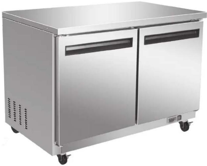
Under-counter Refrigerators and Freezers
natural_image
Exterior view of a stainless steel multi-door refrigerated kitchen appliance (no visible text or symbols)IMPORTANT
Please read this manual completely before attempting to install or operate this equipment.
TABLE OF CONTENTS
SPECIFICATIONS....3
REGISTRATION....4
SAFETY INSTRUCTIONS....5
INTRODUCTION....6
Site Preparation....6
RECEIVING AND INSPECTING 6
Serial Number Location....6
INSTALLATION 7
Location 7
Inside cabinet 7
Outside cabinet 7
Electrical connection....7
Leveling 7
Stabilizing....7
OPERATION 8
Refrigerated Cabinets 8
Defrosting 8
On/Off Switch 8
Front Panel Controls and Indicators....8
Functions....9
Display the set point:....9
Change the set point: 9
Manual Defrost....9
Keyboard Lock 9
Keyboard Unlock....9
Alarm Codes....9
Display and Reset Alarm 9
MAINTENANCE 10
Refrigerators and Freezers 10
Cleaning the Condenser Coil ....10
Stainless Steel Care and Cleaning 10
Gasket Maintenance 11
Doors/Hinges....11
Drain Maintenance 11
Door Replacement and Adjustment.... 11
Open the Bottom Shroud....11
WIRING DIAGRAMS 12
Models: AUC-27R, AUC-48R 12
Models: AUC-27F, AUC-48F 12
Models: AUC-27R, AUC-48R 13
Models: AUC-27F, AUC-48F....14
ARCTIC AIR WARRANTY 15
SPECIFICATIONS
| UNDERCOUNTER & WORKTOP REFRIGERATORS | |||||||||
| MODEL # V/Hz/Ph AMPS | STORAGE | CAPACITYCu-ft | SHELF CAPACITYSq-ft | HP BTU CHARGE | Oz | SHIP WEIGHTLbs | NEMA PLUG | ||
| AUC-27R 115/60/1 5 6.5 | 14 3/8 2800 | 9.5 243 5-15P | |||||||
| AUC-48R 115/60/1 5 12 | 26 | 3/8 3000 9.5 | 300 5-15P | ||||||
| UNDERCOUNTER FREEZERS | |||||||||
| MODEL # V/Hz/Ph AMPS | STORAGE | CAPACITYCu-ft | SHELF CAPACITYSq-ft | HP BTU CHARGE | Oz | SHIP WEIGHTLbs | NEMA PLUG | ||
| AUC-27F | 115/60/1 | 7 6.5 14 1/2 | 3500 | 12.3 291 5-15P | |||||
| AUC-48F | 115/60/1 | 9 | 12 | 26 | 1/2 | 3800 | 13.4 | 340 | 5-15P |
REGISTRATION
The installation date and appliance model must be documented by the end purchaser. Also, refer to the Warranty section for additional details on registering the appliance.
Dealer Information:
Installer Information:
Installation Date:
SAFETY INSTRUCTIONS
General Safety

Arctic Air accepts no responsibility for any situation resulting from work carried out in an unprofessional manner, or from the incorrect interpretation or application of regulations.
General Installation

Incorrect installation or any modifications made to the appliance may damage property or result in injury or death.
Electrical
Electrical connections or any work required on the electrical circuits inside the appliance must be performed by certified technicians in compliance with local, state, and federal regulations.

Make sure all facility electrical connections are in compliance with all local and federal electrical code regulations.
Inspection and Maintenance

Appliance maintenance must be carried out by only by suitably trained personnel.

Before any maintenance work is performed, the appliance must be disconnected from the electrical supply. Apply a lockout tag to the electrical supply connection.
All replacement parts that are not supplied by Arctic Air must be pre-approved before installation.
Repair Work Safety

Repair work must only be performed by Arctic Air or one of its authorized representatives. Arctic Air accepts no responsibility for any situation resulting from work performed by untrained and/or unauthorized technicians.
INTRODUCTION
This manual covers the Under-counter Refrigerators and Freezers. Please read this manual completely before attempting to install or operate this equipment.
Site Preparation
The installation site must be cleaned and prepared prior to the equipment delivery.
- Refer to the SPECIFICATIONS and have a licensed electrician confirm that all electrical requirements are satisfied.
- Confirm that all flooring is structurally strong enough to support the weight of a fully loaded unit; a fully loaded unit can weigh as much as 1500 pounds. Consult with a structural engineer for confirmation if there is any reason to doubt the floor strength.
- Confirm that adequate ventilation has been provided, and that the unit will not be located close to a heat source.
- For all units on casters, confirm that the floor is level where the unit is to be located.
RECEIVING AND INSPECTING
Exercise care to prevent damaging the equipment during unloading and on-site transporting.
- Visually inspect the exterior of the package, skid and/or container. Report any damage to the carrier immediately.
- If any packaging damage is noted, open and inspect the contents with the carrier.
- If concealed damage is discovered after unpacking the equipment notify the carrier. Notification must be made both in writing and verbally.
-
Check the compressor compartment housing and visually inspect the refrigeration package. Confirm that the lines are secure and the base is intact.
-
Request the required damage forms and an equipment damage inspection by the shipping company. The inspection should be performed within 10 days from receipt of the equipment.
- Retain all crating material until an inspection has been performed or waived.
Serial Number Location
The serial number of all self-contained refrigerators and freezers is located inside the unit on the left hand side near the top on the wall. Have the serial number available when calling for parts or service.
This manual covers only standard units. For a custom unit, consult the customer service department. See the customer service phone number listed on the last page.
INSTALLATION
Location
All units are intended for indoor use only. A fully loaded unit can weigh as much as 1500 pounds. Choose a location with a level floor strong enough to support the total weight of a fully loaded unit. Reinforce the floor if necessary.
For the most efficient refrigeration, provide good air circulation around the unit.
Inside cabinet
Do not pack the unit interiors so that air circulation is impeded. The refrigerated air is discharged at the top rear of the unit. Allow for proper air flow from the top rear to the bottom of the unit. Obstructions to this air flow can cause evaporator coil freeze ups and loss of temperature or overflow of water from the evaporator drain pan. The shelves have a rear turn up on them to prevent obstructions to the rear air flow. However, bags and other items located at the rear of the cabinet may obstruct the air flow.
Outside cabinet
Be sure that the unit has access to ample air flow. Avoid hot corners and locations near stoves and ovens. Do not install the unit closer than two inches from a wall. To prevent air obstruction, do not locate large boxes and/or tall stacks of product that might obstruct the air exhaust or the air inlet.
CAUTION
If the unit is laid on its side or back for any reason, allow a minimum of 24 hours in the upright position, before start-up to allow compressor oil to flow back to the sump. Failure to meet this requirement can cause compressor failure, unit damage, and will void the unit warranties.
Electrical connection
Refer to the amperage data provided in the SPECIFICATIONS, the serial tag, the local electrical code and/or the National Electrical Code. Have a licensed electrician confirm that the facility wiring is adequate for the unit and that a protected circuit of the correct voltage and amperage is provided for each unit. Confirm that the unit is connected only to the proper protected power source.
DANGER
TURN THE ON/OFF SWITCH TO OFF AND DISCONNECT THE UNIT FROM THE POWER SOURCE WHENEVER PERFORMING SERVICE, MAINTENANCE FUNCTIONS OR CLEANING THE UNIT.
Leveling
Level the cabinet to improve performance, to better align the doors, to reduce uneven strain on the cabinet and reduce movement of the contents on the shelves. Use a level to level the unit from front to back and side to side. Units supplied with legs have adjustable bullet feet to make the leveling adjustments. If the unit is supplied with casters, no leveling adjustments are available. Ensure the floor is level, where the casters unit is located.
Stabilizing
Casters are provided for convenience, ease of cleaning underneath and for mobility. Install the unit on a level surface, in a stable condition and lock the front wheels to prevent movement.
OPERATION
Refrigerated Cabinets
The internal temperature range for all under-counter refrigerators is 33^ F to 40^ F. The internal temperature range for under-counter freezers is -3^ F to -7^ F. Opening and closing the door must be minimized to allow the unit to maintain optimum refrigeration temperature.
Defrosting
Every 6 hours, the unit turns off and the controller displays the defrost symbol. This allows the evaporator coil to clear the ice. When the coil temperature reaches the terminal temperature (or after 20 minutes) the unit re-starts.
On/Off Switch
The on/off switch is located on the front of the bottom shroud. When the unit is on, the green LED is on.
Front Panel Controls and Indicators
The front panel controls and indicators are used to set and display the unit functions and status.
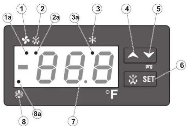
| Callout No. | Control / Indicator | Function |
| 1 Fan | Indicates the fans are running. | |
| 2 Defrost | Press to start the manual defrost cycle. | |
| 3 Compressor | Indicates the compressor is running. | |
| 4 | Up Arrow | To display the last temperature alarm.In programming mode it browses the parameter codes or increases the displayed value. |
| 5 Down Arrow | To display the last temperature alarm.In programming mode it browses the parameter codes or decreases the displayed value. | |
| 6 | SET | Used to display a target set point; in programming mode it elects a parameter or confirm an operation. |
| 7 | Display | Indicates the room temperature, the set points and the alarm codes. |
| 8 | Alarm | Indicates a temperature alarm. |
Key combinations are used to perform functions that cannot be performed with a single key.
| Key Combinations | ||
| Press Keys | Result | |
| Up Arrow | Down Arrow | Locks and unlocks the keyboard. |
| SET Down Arrow | Enters the programming mode. | |
| SET Up Arrow | Returns to the room temperature display. | |
The LED functions display operational conditions.
| Callout No. | Mode | LED Function |
| 1a | On | Fans enabled |
| Flashing | Fans delay after defrost in progress | |
| 2a | On | Defrost enabled |
| Flashing | -Programming phase (flashing with “icon”) - Drip time in progress | |
| 3a | On | Compressor enabled |
| Flashing | -Programming phase (flashing with “icon”) -Anti-short cycle delay enabled | |
| 8a | On | A temperature alarm happened |
Functions
Display the set point:
- Press and release the SET button, the set point value is displayed.
- Press and release the SET button (again) or wait five seconds to return to the probe value display.
Change the set point:
- To change the set point value, press the SET button and hold for a minimum of two seconds.
The set point value is displayed and the Compressor LED starts blinking.
-
For the next ten seconds, the set value can be changed using the Up Arrow or the Down Arrow buttons.
-
To save the new set point value press the SET key again (or wait ten seconds).
Manual Defrost
Press the Defrost button and hold for a minimum of two seconds. The manual defrost cycle starts.
Keyboard Lock
- Press the Up Arrow and Down Arrow buttons and hold for a minimum of three seconds.
- The "POF" message is displayed when the keyboard is locked. With the keyboard locked only the set point or the max/min temperature is displayed.
- If any key is pressed for more than three seconds the "POF" message is displayed.
Keyboard Unlock
Press the Up Arrow and Down Arrow buttons and hold for a minimum of three seconds. The "Pon" message is displayed when the keyboard is unlocked.
Alarm Codes
| CODE | CAUSE OUTPUTS | |
| P1 | Room probe failure | Compressor output according to par Con and COF |
| P2 | Evaporator probe failure | Defrost end is timed |
| P3 | Condenser probe failure | Outputs unchanged |
| HA | Maximum temperature alarm | Outputs unchanged |
| LA | Minimum temperature alarm | Outputs unchanged |
| dA Door open Compressor and fans restart | ||
| EA External alarm Outputs unchanged | ||
| CA | Serious external alarm (i1F=bal) | All outputs off |
| CSd | Condenser alarm | All outputs off |
Display and reset alarm
- Press the Up Arrow and Down Arrow buttons to display the alarm code.
- Press and hold the SET button until the reset (rst) message is displayed then release.
Press the SET button again, the reset (rst) message blinks and the room temperature is displayed.
MAINTENANCE
DANGER
TURN OFF THE POWER SWITCH AND DISCONNECT THE UNIT FROM THE POWER SOURCE WHENEVER PERFORMING SERVICE/MAINTENANCE FUNCTIONS AND/OR CLEANING THE REFRIGERATED AREA.
Refrigerators and Freezers
Clean the interior and exterior using soap and warm water. If this is not sufficient, use ammonia and water or a nonabrasive liquid cleaner. When cleaning the exterior, always rub with the stainless steel grain to avoid marring the finish.
Do not use an abrasive cleaner, it may scratch the stainless steel and/or the plastic. Abrasive cleaners can also damage the breaker strips and gaskets.
Cleaning the Condenser Coil
Clean the condenser coil a minimum of every 90 days. If there is a large amount of debris, dust or grease accumulation prior to the 90 day cycle, reduce the cleaning cycle to every 30 days.
If the buildup on the coil consists of only light dust and debris, clean the condenser coil using a brush. For heavier dust buildup, use a vacuum or compressed air.
If heavy grease is present use a refrigeration degreasing agent designed specifically for the condenser coils. Spray the condenser coil with degreasing agent and blow through with compressed air.
Failure to maintain a clean condenser coil can initially cause high temperatures and excessive run times. Continuous operation with dirty or clogged condenser coils may result in compressor failures. Neglecting the condenser coil cleaning procedures will void any warranties associated with the compressor.
CAUTION
Never use a high pressure water wash for this cleaning procedure as water can damage the electrical components located near or on the condenser coil.
Stainless Steel Care and Cleaning
Stainless steel contains 70-80% iron which will rust. It also contains 12-30% chromium which forms an invisible passive film over the steel's surface that acts as a corrosion shield. As long as the protective layer remains intact, the metal remains stainless. If the film is broken or contaminated, outside elements can break down the steel and begin to form rust or discoloration.
To properly clean stainless steel, use soft cloths or plastic scouring pads.
CAUTION
Never use steel pads, wire brushes or scrapers to clean stainless steel surfaces.
Cleaning solutions must be alkaline based or non-chloride cleaners. Any cleaner containing chlorides will damage the stainless steel protective film. Chlorides are also commonly found in hard water, salts, and household and industrial cleaners. If cleaners containing chlorides are used, be sure to rinse repeatedly and dry thoroughly upon completion.
Perform routine stainless steel cleaning with soap and water. Extreme stains or grease should be cleaned with a non-abrasive cleaner and plastic scrub pad (rub with the grain). There are also stainless steel cleaners available which can restore the protective layer and preserve the finish.
Early signs of stainless steel breakdown may consist of small pits and cracks. If these early signs are present, clean thoroughly and apply a cleaner specifically designed for stainless steel cleaners to attempt to restore the passivity.
CAUTION
Never use an acid based cleaning solution. In addition, many food products have an acidic content which can deteriorate the finish. Be sure to clean the stainless steel surfaces of all food products. Common acidic based food items include; tomatoes, peppers and other vegetables.
Gasket Maintenance
Gaskets require regular cleaning to prevent mold and mildew buildup and to maintain the gasket elasticity. Clean gaskets with warm soapy water. Avoid full strength cleaning products on gaskets, this can cause the gaskets to become brittle and prevent proper sealing. Never use sharp tools or knives, which could tear the gasket and/or rip the bellows, to scrape or clean the gasket.
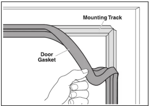
Gaskets are easy to replace and do not require the use of tools. To remove and replace the Dart style gasket, pull the gasket out of the groove in the door and press the new gasket back into place.
Doors/Hinges
Over time the door hinges may become loose. If the doors are loose or sagging, this can cause the hinge to pull out of the frame which may damage both the doors and the door hinges. Tighten the screws that mount the hinge brackets to the frame of the unit. If this does not solve the issue call a qualified service agent.
Drain Maintenance
The drain located inside all of the units removes the condensation from the evaporator coil and evaporates it at an external condensate evaporator pan. Moving or bumping the drain may cause the drain to become loose or disconnected. If excessive water accumulates on the inside of the unit make sure the drain tube is connected from the evaporator housing to the condensate evaporator drain pan. If water has collected underneath the unit, check the condensate evaporator drain tube to be sure it is still located inside the drain pan. Leveling the unit is important because the units are designed to drain properly when level. If the floor is not level drain problems may occur. Be sure all drain lines are free of obstructions. Food products blocking drain lines is a common cause of water back up and overflow.
Door Replacement and Adjustment
- Open the door until it remains open, about 100^ to 110^ .
- Loosen and remove the bottom screw on the self-closing cartridge. Remove the three hinge screws, then slide the door down and out.
- To prepare a new door, rotate the square head of the cartridge shaft approximately 120^ in the direction the door closes. This action preloads the hinge and it is now ready to be secured to the bottom hinge.
- From the closed position, hold the door at about 100^ , insert the bottom hinge over the square shaft of the cartridge so that the hinge is facing the cabinet. Once positioned, insert and fasten the mounting screw.
- Maintain the door/hinge assembly at about 100^ and slide it up to the top hinge pin. Confirm proper alignment, and then fasten the bottom hinge.
- The door must swing closed by itself with no restriction. Confirm that the door swings freely.
Open the Bottom Shroud
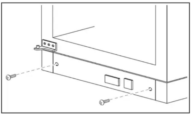
Loosen and remove the screw from the two holes in front of the bottom shroud, the bottom shroud can be moved out.
natural_image
Technical line drawing of a cabinet or rack unit with mounting hardware and mounting holes (no text or symbols)WIRING DIAGRAMS
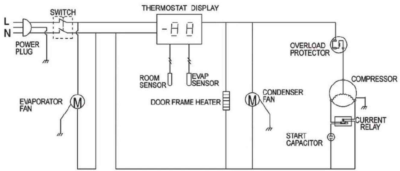
Models: AUC-27R, AUC-48R
flowchart
graph TD
    A["POWER PLUG"] --> B["SWITCH"]
    B --> C["THERMOSTAT DISPLAY"]
    C --> D["ROOM SENSOR"]
    C --> E["EVAP SENSOR"]
    D --> F["DOOR FRAME HEATER"]
    E --> F
    F --> G["CONDENSER FAN"]
    G --> H["START CAPACITOR"]
    H --> I["OVERLOAD PROTECTOR"]
    I --> J["COMPRESSOR"]
    J --> K["CURRENT RELAY"]
    L["EVAPORATOR FAN"] --> M["M"]
    M --> N["Ground"]
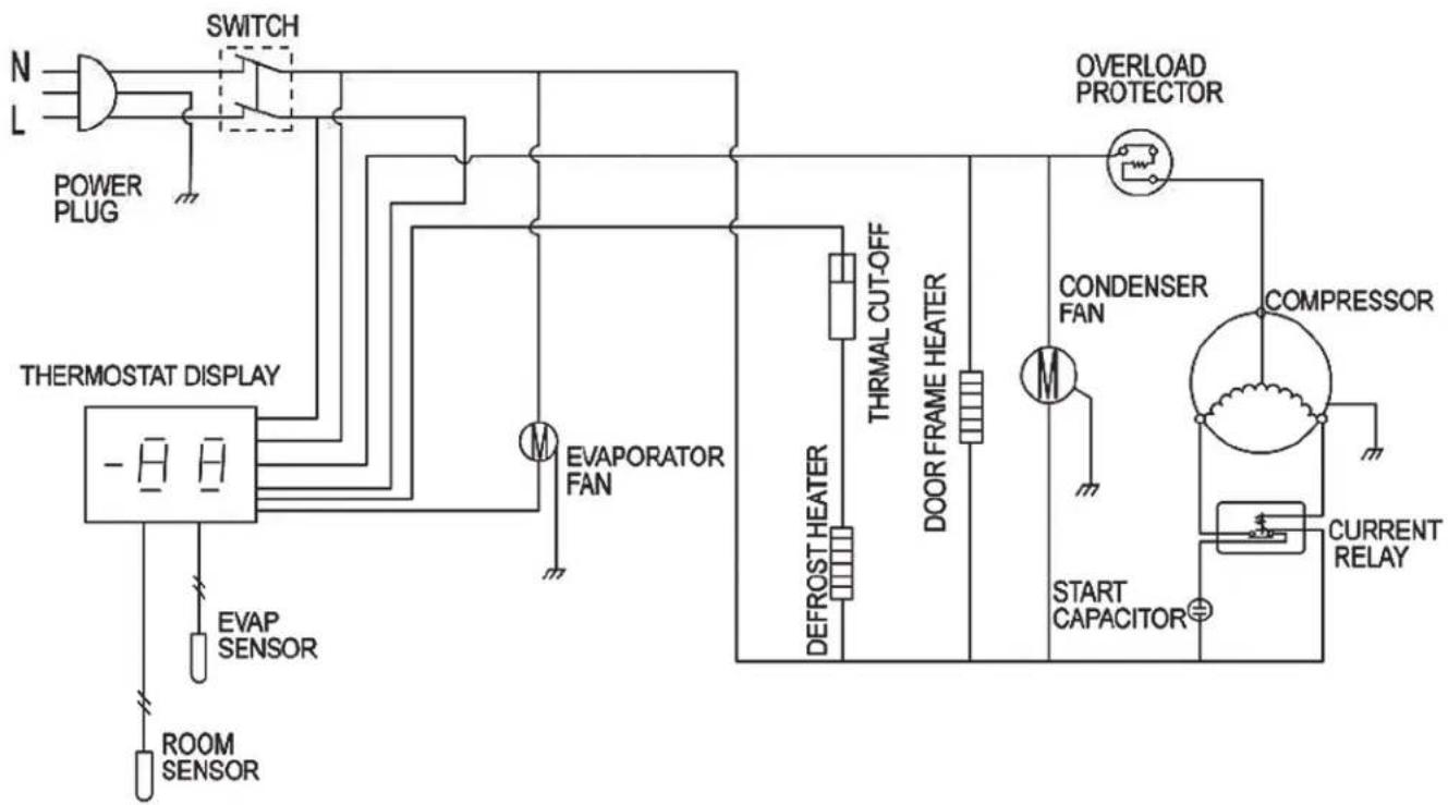
Models: AUC-27F, AUC-48F
flowchart
graph TD
    A["N"] --> B["POWER PLUG"]
    B --> C["SWITCH"]
    C --> D["THERMOSTAT DISPLAY"]
    D --> E["EVAP SENSOR"]
    E --> F["ROOM SENSOR"]
    F --> G["THERMOSTAT DISPLAY"]
    G --> H["EVAP FAN"]
    H --> I["THRMAL CUT-OFF"]
    I --> J["DEFROSTHEATER"]
    J --> K["DOOR FRAME HEATER"]
    K --> L["CONDENSER FAN"]
    L --> M["START CAPACITOR"]
    M --> N["CURRENT RELAY"]
    N --> O["COMPRESSOR"]
    O --> P["OVERLOAD PROTECTOR"]
    P --> Q["CONTENTS"]
Models: AUC-27R, AUC-48R
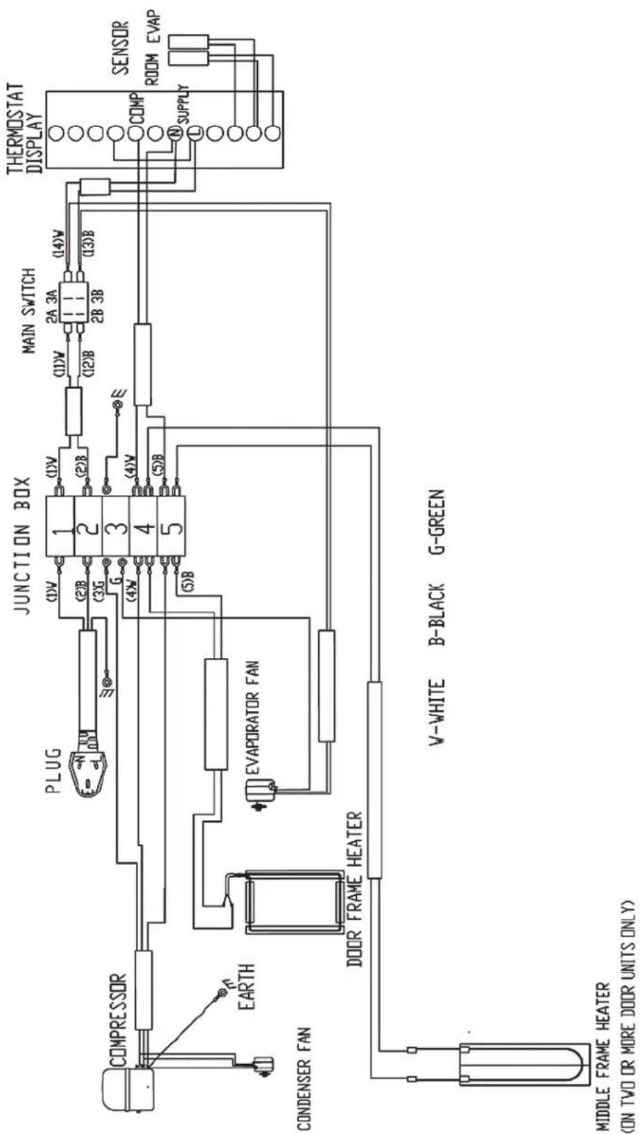
flowchart
graph TD
    A["COMPRESSOR"] --> B["EARTH"]
    B --> C["CONDENSER FAN"]
    C --> D["DOOR FRAME HEATER"]
    D --> E["MIDDLE FRAME HEATER (ON TWO OR MORE DOOR UNITS ONLY)"]
    F["JUNCTION BOX"] --> G["PLUG"]
    G --> H["(1)V (2)B (3)G G"]
    H --> I["1 2 3 4 5"]
    I --> J["(1)V (2)B"]
    J --> K["(1)V (12)B"]
    K --> L["MAIN SWITCH"]
    L --> M["(2A 3A 2B 3B)"]
    M --> N["(14)V (13)B"]
    N --> O["THERMOSTAT DISPLAY"]
    P["V-WHITE B-BLACK G-GREEN"] --> Q["SENSOR ROOM EVAP"]
    R["Evaporator Fan"] --> S["N SUPPLY"]
    T["Ground"] --> U["Ground"]
Models: AUC-27F, AUC-48F
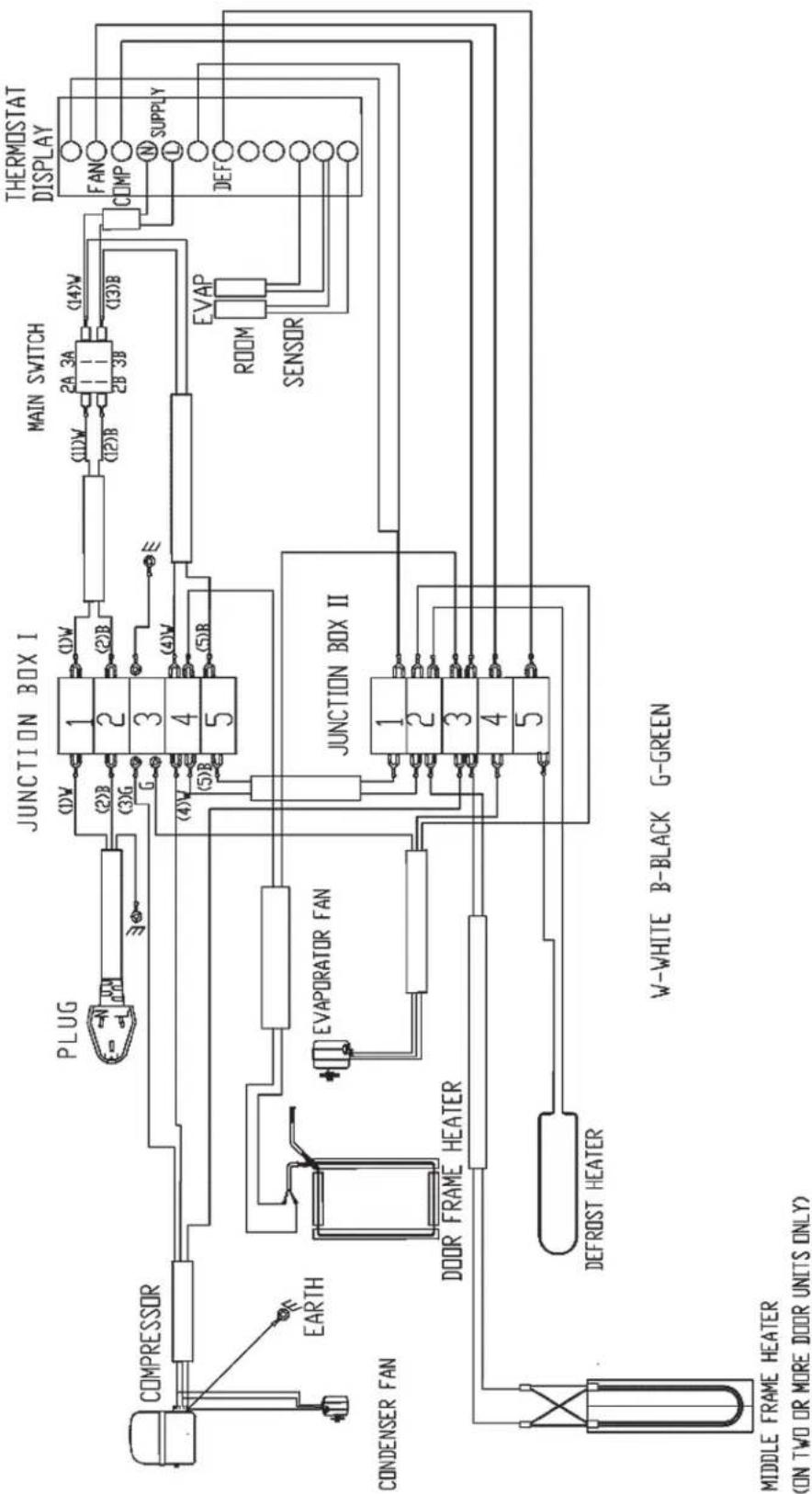
flowchart
graph TD
    A["COMPRESSOR"] --> B["EARTH"]
    B --> C["CONDENSER FAN"]
    C --> D["DOOR FRAME HEATER"]
    D --> E["DEFROST HEATER"]
    E --> F["MIDDLE FRAME HEATER (ON TWO OR MORE DOOR UNITS ONLY)"]

    G["PLUG"] --> H["JUNCTION BOX I"]
    H --> I["MAIN SWITCH"]
    I --> J["THERMOSTAT DISPLAY"]

    K["EVAP"] --> L["ROOM SENSOR"]
    L --> M["FAN COMP SUPPLY DEF"]

    N["JUNCTION BOX II"] --> O["1 2 3 4 5"]

    P["W-WHITE B-BLACK G-GREEN"] --> Q["1 2 3 4 5"]
ARCTIC AIR WARRANTY
One year parts & labor warranty
Arctic Air warrants to the original purchaser, all of its new equipment to be free from defects in material or workmanship, under normal use and maintenance service, for a period of one (1) year from the date of original purchase or 15 months after shipment date from the manufacturer, whichever occurs first. Warranty coverage is limited to the repair and/or replacement, including labor charges, of defective parts and/or assemblies. The labor warranty shall include straight time labor charges and travel charges within 100 miles roundtrip. Warranty service must be arranged by calling 1-855-431-5558 for service in the United States and Canada. Warranty service coverage is not offered outside of the United States and Canada.
Additional four year compressor warranty
In addition to the one (1) year warranty stated above, Arctic Air warrants its compressor units to be free from defects in both material and workmanship under normal and proper use and maintenance service for a period of four (4) additional years from the date of original installation but not to exceed five (5) years and three (3) months after shipment from Arctic Air.
The four (4) year extended compressor warranty applies only to the compressor part itself and does not apply to any other parts, components, or labor charges involved in replacement of compressor.
Conditions
All service under this warranty, for either labor or parts, must be performed by a preferred service provider arranged by the Arctic Air warranty Center at 1-855-431-5558. Warranty claims should include model number of the unit, batch and serial number of the unit, and proof of purchase. Service coverage is limited to units located in the United States and Canada only.
Limitations & Exclusive Warranty
This parts and labor warranty is the sole and exclusive warranty remedy offered by Arctic Air. Arctic Air's sole obligation under this warranty is limited to either repair or replacement of parts and is subject to the limitations listed below.
- Arctic Air will bear no responsibility or liability for any equipment which has been misapplied, mishandled, misused, subjected to harsh chemical action, or external causes such as the use of extension cords, electrical power fluctuations, lack of proper maintenance, non-factory approved revisions or modifications, or equipment damaged by fire, flood, or other acts of God.
- Arctic Air will bear no responsibility for consequential loss or damages such as, including but not limited to, economic loss, profit loss, personal injury, property damage, damage during transit, losses or damages arising from food or product spoilage claims.
- Arctic Air shall bear no responsibility for parts or labor coverage for component failure or other damages resulting from improper usage, installation, or maintenance as described in the owner's manual.
- Exceptions to one (1) year part warranty other than additional four (4) year compressor warranty: Light bulbs and door gaskets are limited to 90 day warranty period.
- Arctic Air equipment is intended for commercial use only and this warranty is void if the equipment is installed in other than commercial applications.
- All other warranties, either express or implied, arising under law or equity or custom of the trade, including but not limited to, warranties or merchantability or fitness for a particular purpose are excluded. Arctic Air's liability on any claim, including but not limited to negligence, shall not exceed the price of the equipment that gives rise to the claim.
Commercial Freezers & Refrigerators
Broich Enterprises, Inc. / Arctic Air
6440 City West Parkway
Eden Prairie, MN 55344
Phone: 952-941-2270
Fax: 952-941-3066
Website: www.arcticairco.com
- Under-counter Refrigerators and Freezers
- IMPORTANT
- TABLE OF CONTENTS
- REGISTRATION
- SAFETY INSTRUCTIONS
- General Safety
- General Installation
- Electrical
- Inspection and Maintenance
- Repair Work Safety
- INTRODUCTION
- Site Preparation
- RECEIVING AND INSPECTING
- Serial Number Location
- INSTALLATION
- Location
- Inside cabinet
- Outside cabinet
- CAUTION
- Electrical connection
- DANGER
- Leveling
- Stabilizing
- OPERATION
- Refrigerated Cabinets
- Defrosting
- On/Off Switch
- Front Panel Controls and Indicators
- Functions
- Display the set point:
- Change the set point:
- Manual Defrost
- Keyboard Lock
- Keyboard Unlock
- Display and reset alarm
- MAINTENANCE
- Refrigerators and Freezers
- Cleaning the Condenser Coil
- Stainless Steel Care and Cleaning
- Gasket Maintenance
- Doors/Hinges
- Drain Maintenance
- Door Replacement and Adjustment
- Open the Bottom Shroud
- WIRING DIAGRAMS
- ARCTIC AIR WARRANTY
- One year parts & labor warranty
- Additional four year compressor warranty
- Conditions
- Limitations & Exclusive Warranty
Brand : Arctic Air
Model : AUC27F
Category : Freezer