
Snaptricity SCBE-75 - Toy Snap Circuits - Free user manual and instructions
Find the device manual for free Snaptricity SCBE-75 Snap Circuits in PDF.


| Product Type | Educational Electronics Kit |
| Model | Snaptricity SCBE-75 |
| Brand | Snap Circuits |
| Age Recommendation | 8 years and up |
| Number of Projects | 79 |
| Base Grid Dimensions | 11.0 x 7.7 inches (27.9 x 19.6 cm) |
| Power Source | 3 AA batteries (not included) |
| Battery Type | 1.5V alkaline recommended |
| Number of Parts | Over 40 |
| Key Components | Motor, Electromagnet, Meter, Switches, Lamps, Compass, Jumper Wires |
| Learning Topics | Static electricity, circuits, magnetism, electromagnetism, electrochemistry |
| Safety Warnings | Choking hazard; shock hazard; do not connect to wall outlet; moving parts |
| Recommended for | STEM education, hobbyists, beginners |
| Manual Languages | English |
| Patent Numbers | 7,144,255; 7,273,377 |
| Warranty | Not specified; contact manufacturer for defective parts |
| Replacement Parts | Available at snapcircuits.net |
| Certification | Conforms to ASTM F963 |
| Package Weight (approx.) | 1.5 lbs (0.68 kg) |
| Assembly Required | Yes, snap-together blocks |
Frequently Asked Questions - Snaptricity SCBE-75 Snap Circuits
User questions about Snaptricity SCBE-75 Snap Circuits
0 question about this device. Answer the ones you know or ask your own.
Ask a new question about this device
Download the instructions for your Toy in PDF format for free! Find your manual Snaptricity SCBE-75 - Snap Circuits and take your electronic device back in hand. On this page are published all the documents necessary for the use of your device. Snaptricity SCBE-75 by Snap Circuits.
USER MANUAL Snaptricity SCBE-75 Snap Circuits
Copyright © 2011 by ELENCO® All rights reserved. No part of this book shall be reproduced 753303
by any means; electronic, photocopying, or otherwise without written permission from the publisher.
REV-A Revised 2011
Patent #'s: 7,144,255, 7,273,377, & other patents pending
Table of Contents
For the best learning experience, do the projects in order.
| Basic Troubleshooting 1 | Advanced Troubleshooting 8 | |
| Parts List 2 | Project Listings 9 | |
| How to Use It 3 | Projects 1 - 79 | 10 - 88 |
| About Your Snaptricity® Parts 4 | Other Snap Circuits® Projects | 90 |
| DO's and DON'Ts of Building Circuits 7 |

WARNING FOR ALL PARTS WITH A ⚠ SYMBOL - Moving parts. Do not touch the motor or fan during operation. Do not lean over the motor. Do not launch the fan at people, animals, or objects. Eye protection is recommended.


WARNING: SHOCK HAZARD - Never connect your Snaptricity® set to the electrical outlets in your home in any way!

WARNING: CHOKING HAZARD - Small parts. Not for children under 3 years.
Conforms to ASTM F963
WARNING: Always check your wiring before turning on a circuit. Never leave a circuit unattended while the batteries are installed. Never connect additional batteries or any other power sources to your circuits. Discard any cracked or broken parts.
Basic Troubleshooting
- Most circuit problems are due to incorrect assembly, always double-check that your circuit exactly matches the drawing for it.
- Be sure that parts with positive/negative markings are positioned as per the drawing.
- Be sure that all connections are securely snapped.
- Try replacing the batteries.
- If the motor spins but does not balance the fan, check that there is a black plastic piece with three prongs on the motor shaft. In case it is damaged or lost, a spare is included with your kit. Pry the broken one off with a screwdriver and push the spare one on the shaft.
ELENCO® is not responsible for parts damaged due to incorrect wiring.
Note: If you suspect you have damaged parts, you can follow the Advanced Troubleshooting procedure on page 8 to determine which ones need replacing.
WARNING:

This product contains a small magnet. Swallowed magnets can stick together across intestines causing serious infections and death. Seek immediate medical attention if magnet is swallowed or inhaled.

Batteries:
- Use only 1.5V AA type, alkaline batteries (recommended, not included).
- Insert batteries with correct polarity.
• Non-rechargeable batteries should not be recharged. Rechargeable batteries should only be charged under adult supervision, and should not be recharged while in the product. -
Do not mix alkaline, standard (carbon-zinc), or rechargeable (nickel-cadmium) batteries.
-
Do not mix old and new batteries.
- Remove batteries when they are used up.
- Do not short circuit the battery terminals.
- Never throw batteries in a fire or attempt to open its outer casing.
- Batteries are harmful if swallowed, so keep away from small children.
Parts List (Colors and styles may vary) Symbols and Numbers
Qty. ID Name Symbol Part # Qty. ID Name Symbol Part #
| ☐1 | Base Grid(11.0" x 7.7") |  | 6SCBG | ☐1 | M1 | Motor 6SCM1 | 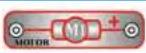 | ||
| ☐3 | 1 | 1-Snap Wire 6SC01 | ☐1 | Fan Blade 6SCM1F |  | ||||
| ☐6 | 2 | 2-Snap Wire 6SC02 | ☐1 | String 6SCM1S |  | ||||
| ☐3 | 3 | 3-Snap Wire 6SC03 | ☐1 | Spare Motor Top 6SCM1T |  | ||||
| ☐1 | 4 | 4-Snap Wire 6SC04 | ☐1 | M3 | Electromagnet 6SCM3 |  | |||
| ☐1 | 5 | 5-Snap Wire 6SC05 | ☐1 | Iron Core Rod(46mm) |  | 6SCM3C | |||
| ☐1 | 6 | 6-Snap Wire 6SC06 | ☐1 | Bag of Paper Clips |  | 6SCM3P | |||
| ☐1 | B3 | Battery Holder - uses3 1.5V type AA (not included) | 6SCB3 | ☐1 | Thin Rod |  | MWK01P5 | ||
| ☐1 | Compass | 6SCCOM | ☐1 | Grommet |  | 662510 | |||
| ☐1 | Copper Electrode | 6SCEC | ☐1 | M5 | Meter 6SCM5 |  | |||
| ☐1 | Zinc Electrode | 6SCEZ | ☐1 | Magnet | 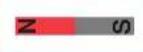 | 6SCMAG | |||
| ☐1 | Iron Filings | 6SCIF | ☐1 | Nut-snap |  | 6SCNS | |||
| ☐1 | Jumper Wire (Black) | 6SCJ1 | ☐1 | S2 | Press Switch |  | 6SCS2 | ||
| ☐1 | Jumper Wire (Red) | 6SCJ2 | ☐2 | S5 | Slide Switch |  | 6SCS5 | ||
| ☐3 | L4 | Lamp | 6SCL4 | You may order additional / replacement parts at ourwebsite: www.snapcircuits.net | |||||
How to Use It
Snaptricity® uses building blocks with snaps to build the different electrical and electronic circuits in the projects. Each block has a function: there are switch blocks, lamp blocks, battery blocks, different length wire blocks, etc. These blocks are different colors and have numbers on them so that you can easily identify them. The blocks you will be using are shown as color symbols with level numbers next to them, allowing you to easily snap them together to form a circuit.
For Example:
This is the switch block which is green and has the marking ☑ on it. The part symbols in this booklet may not exactly match the appearance of the actual parts, but will clearly identify them.

This is a wire block which is blue and comes in different wire lengths.
This one has the number ②, ③, ④, ⑤, or ⑥ on it depending on the length of the wire connection required.

There is also a 1-snap wire that is used as a spacer or for interconnection between different layers.

You need a power source to build each circuit. This is labeled B3 and requires three (3) "AA" batteries (not included with the Snaptricity® kit).

natural_image
Hand holding two batteries in a clear plastic case (no visible text or symbols)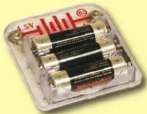
natural_image
Close-up of a transparent plastic battery pack with four black cylindrical cells, no visible text or symbols on the main body.A large clear plastic base grid is included with this kit to help keep the circuit blocks properly spaced. You will see evenly spaced posts that the different blocks snap into. The base has rows labeled A-G and columns labeled 1-10.
Next to each part in every circuit drawing is a small number in black. This tells you which level the component is placed at. Place all parts on level 1 first, then all of the parts on level 2, then all of the parts on level 3, etc.
Some circuits use the jumper wires to make unusual connections. Just clip them to the metal snaps or as indicated.

Note: While building the projects, be careful not to accidentally make a direct connection across the battery holder (a "short circuit"), as this may damage and/or quickly drain the batteries.
About Your Snaptricity® Parts
(Part designs are subject to change without notice).
BASE GRID

natural_image
Close-up of a white perforated metal plate with hexagonal holes, placed on a yellow background (no text or symbols visible)The base grid is a platform for mounting parts and wires. It functions like the printed circuit boards used in most electronic products, or like how the walls are used for mounting the electrical wiring in your home.
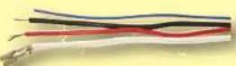
SNAP WIRES & JUMPER WIRES

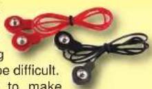
The blue snap wires are wires used to connect components.
They are used to
The red and black
jumper wires make
flexible connections
for times when using
the snap wires would be difficult.
They also are used to make
connections off the base grid (like the projects using water).
Wires transport
electricity just like
pipes are used to
transport wa
The colorful plastic coating protects them and prevents electricity from getting in or out.
BATTERY HOLDER PRES
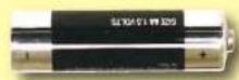
The batteries (B3) produce an electrical voltage using a chemical reaction. This "voltage" can be thought of as electrical pressure, pushing electricity through a circuit just like a pump pushes water through pipes. This voltage is much lower and much safer than that used in your house wiring. Using more batteries increases the "pressure", therefore, more electricity flows.
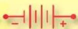
The funny marking on the battery holder is the standard battery symbol used in electrical wiring diagrams. These wiring diagrams are called schematics, and are used in everything from house wiring to complex radios.
Battery Symbol

natural_image
Close-up of a transparent plastic electrical contactor with metal pins and a red '4.5V' label (no readable text or symbols beyond branding)Battery Holder (B3)
SWITCH

The press switch (S2)
connects (pressed,
"ON"
disconnects (not
pressed, "OFF")
Press Switch (S2)
the wires in a circuit.
When ON it has no effect on circuit performance. It turns on electricity just like a faucet turns on water from a pipe.
The electrical symbol for a press switch is shown here.

Press Switch Symbol
SLIDE SWITCH
Slide Switch (S5)

The slide switch
(S5) connects
(ON) the center
snap to one of the
other two snaps.
When connected it has
no effect on circuit
performance. It directs electricity just like a value controls water in a pipe.
The electrical symbol is shown here. It resembles the symbol for a door used in architect drawings for a house.

Slide Switch Symbol
Engineers call this type of switch a SPDT (Single-Pole Double-Throw), representing how one point can be connected to either of two others.
About Your Snaptricity® Parts
METER
The meter (M5) is an important measuring device. You will use it to measure the voltage (electrical pressure) and current (how fast electricity is flowing) in a circuit.

The electrical symbol for a meter is shown below.

The meter measures voltage when connected in parallel to a circuit and measures the current when connected in series in a circuit.
This meter has one voltage scale (5V) and two current scales (1mA and 1A). These use the same meter but with internal components that scale the measurement into the desired range. This will be explained more later. Note: Your M5 meter is a simple meter. Don't expect it to be as accurate as normal electronic test instruments.
Inside the meter there is a fixed magnet and a moveable coil around it. As current flows through the coil, it creates a magnetic field. The interaction of the two magnetic fields causes the coil (connected to the pointer) to move (deflect).

MOTOR
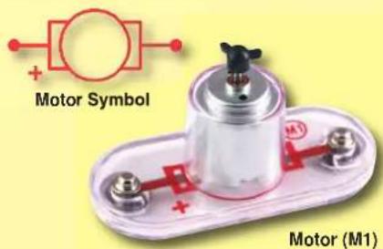
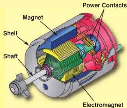
The motor (M1) converts electricity into mechanical motion. An electric current in the motor will turn the shaft and the motor blades, and the fan blade if it is on the motor. The electrical symbol for a motor is also shown here.

natural_image
Red circular fan-shaped object with three blades, labeled 'Fan' at bottom left (no other text or symbols)How does electricity turn the shaft in the motor? The answer is magnetism. Electricity is closely related to magnetism, and an electric current flowing in a wire has a magnetic field similar to that of a very, very tiny magnet. Inside the motor is a coil of wire with many loops wrapped around metal plates. This is called an electromagnet. If a large electric current flows through the loops, it will turn ordinary metal into a magnet. The motor shell also has a magnet on it. When electricity flows through the electromagnet, it repels from the magnet on the motor shell and the shaft spins. If the fan is on the motor shaft, then its blades will create airflow.
About Your Snaptricity® Parts
ELECTROMAGNET
The electromagnet (M3) is a large coil of wire, which acts like a magnet when electricity flows through it. Placing an iron bar inside increases the magnetic effects. The electromagnet can store electrical energy in a magnetic field.
The properties of the electromagnet will be explained in the projects. Note that magnets can increase magnetic media like floppy disks.

Electromagnet (M3)

Iron Core Rod (usually placed in electromagnet)
The grommet will be used to hold the iron core rod on the electromagnet.

Grommet
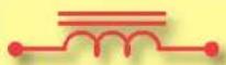
Electromagnet Symbol with Rod Inside

Electromagnet Symbol without Rod
LAMP
A light bulb, such as in the 4.5V lamps (L4), contains a special thin high-resistance wire. When a lot of electricity flows through, this wire
gets so hot it glows bright. Voltages above the bulb's rating can burn out the wire.

Lamp (L4)
The electrical symbol for a lamp is shown here, though other symbols are also used in the industry.

Lamp Symbol
OTHER PARTS
The magnet is an ordinary magnet like those in your home.

The compass is a standard compass. The red needle will point toward the strongest magnetic field around it, usually the north pole of the earth.

natural_image
Close-up of a compass needle with red needle and green needle, no visible text or symbolsThe iron filings are tiny fragments of iron in a sealed case. They will be used in magnetism projects.
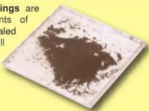

The copper and zinc electrodes are just metals that will be used for electrochemical projects.
The nut-snap is an iron nut mounted on a snap for special projects.


The string will be used in special projects. You can use your own string if you need more.
The thin rod is an iron bar for special projects.


The Paper Clips will be used for special projects. You can use your own if you need more, but they must be metal.
The spare motor top is provided in case you break the one on the motor. Use a screwdriver to pry the broken one off the motor, then push the spare one on.

DO's and DON'Ts of Building Circuits
After building the circuits given in this booklet, you may wish to experiment on your own. Use the projects in this booklet as a guide, as many important design concepts are introduced throughout them. Every circuit will include a power source (the batteries), a resistance (which might be a lamp, motor, electromagnet, etc.), and wiring paths between them and back. You must be careful not to create "short circuits" (very low-resistance paths across the batteries, see examples below) as this will damage components and/or quickly drain your batteries. ELENCO® is not responsible for parts damaged due to incorrect wiring.
Here are some important guidelines:
ALWAYS use eye protection when experimenting on your own.
ALWAYS include at least one component that will limit the current through a circuit, such as a lamp, motor, or electromagnet.
ALWAYS use the meter and switches in conjunction with other components that will limit the current through them. Failure to do so will create a short circuit and/or damage those parts.
ALWAYS disconnect your batteries immediately and check your wiring if something appears to be getting hot.
ALWAYS check your wiring before turning on a circuit.
NEVER connect to an electrical outlet in your home in any way.
NEVER leave a circuit unattended when it is turned on.
NEVER touch the motor when it is spinning at high speed.
For all of the projects given in this book, the parts may be arranged in different ways without changing the circuit. For example, the order of parts connected in series or in parallel does not matter — what matters is how combinations of these sub-circuits are arranged together.
Examples of SHORT CIRCUITS - NEVER DO THESE!!!
Placing a 3-snap wire directly across the batteries is a SHORT CIRCUIT.


This is also a SHORT CIRCUIT.

flowchart
graph TD
    A["Power Supply"] --> B["Battery"]
    B --> C["Switch"]
    C --> D["Switch"]
    D --> E["Ground"]
    style A fill:#f9f,stroke:#333
    style B fill:#bbf,stroke:#333
    style C fill:#bfb,stroke:#333
    style D fill:#ffb,stroke:#333
    style E fill:#fff,stroke:#333
    note1["NEVER DO!"]
    note2["SHORT CIR"]
    note3["Never DO!"]
    note4["What is to circle CIP show. The pre portion from"]
    note5["NOT ON"]
When the switch (S5) is turned on, this large circuit has a SHORT CIRCUIT path (as shown by the arrows). The short circuit prevents any other portions of the circuit from ever working.
You are encouraged to tell us about new circuits you create. If they are unique, we will post them with your name and state on our website at www.snapcircuits.net/kidkreations.htm. Send your suggestions to ELENCO®: elenco@elenco.com.
ELENCO® provides a circuit designer so that you can make your own Snap Circuits® drawings. This Microsoft® Word document can be downloaded from www.snapcircuits.net/SnapDesigner.doc or through the www.snapcircuits.net web site.

WARNING: SHOCK HAZARD - Never connect your Snaptricity® set to the electrical outlets in your home in any way!
Advanced Troubleshooting (Adult supervision recommended)
ELENCO® is not responsible for parts damaged due to incorrect wiring.
If you suspect you have damaged parts, you can follow this procedure to systematically determine which ones need replacing:
- 4.5V lamps (L4), motor (M1), and battery holder (B3): Place batteries in holder. Place the 4.5V lamp directly across the battery holder, it should light. Do the same with the motor (motor + to battery +), it should spin to the right at high speed (use two 1-snap wires as spacers). If none work then replace your batteries and repeat, if still bad then the battery holder is damaged.
- Set the motor (M1) by itself and place the fan on it. If the Motor (M1) does not balance the fan evenly: Inspect the black plastic piece at the top of the motor shaft, it should have 3 prongs. If missing or broken, replace it with the spare that is included with this kit (a broken one can be removed with a screwdriver). If the motor is fine, then inspect the fan.
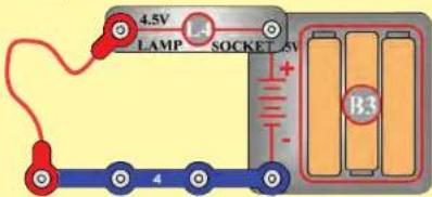
- Jumper wires: Use this mini-circuit to test each jumper wire, the lamp should light.

- Snap wires: Use this mini-circuit to test each of the snap wires, one at a time. The lamp should light.
- Slide switch (S5): Build project 10. With the switch in the left position (C), the left lamp should be on. With the switch in the right position (B), the right lamp should be on.
- Press switch (S2): Build project 75. When you press the switch, the lamp should light.
- Meter (M5): Build project 75, but replace the 3-snap wire with the meter.
a. Set the meter to the 5V scale and push the press switch. The meter should read at least 2.5V.
b. Set the meter to the 1mA scale and push the switch. The reading should be over maximum.
c. Set the meter to the 1A scale and push the switch. The meter should show a small current.
-
Electromagnet (M3): Build project 46 and place the iron core rod in the electromagnet. When you press the switch (S2), the rod in the electromagnet should act like a magnet.
-
Iron filings: Sometimes the filings may stick to the case, making it appear cloudy. Move a magnet (the one in this kit or a stronger one in your home) across the case to clean them off.
- Compass and magnet: The red compass needle should point north, unless it is near a magnet or large iron object. The red compass needle will point toward the black (S) side of the magnet.
ELENCO®
150 Carpenter Avenue Wheeling, IL 60090 U.S.A.
Phone: (847) 541-3800
Fax: (847) 520-0085
e-mail: help@elenco.com
Website: www.elenco.com
You may order additional / replacement parts at:
www.snapcircuits.net
Project Listings
Project # Description Page # Project # Description Page # Project # Description Page #
Welcome to Electronics
1 Electronic Playground 10
2 Parallel Play 11
3 Wicked Switches 12
4 Spinning Cylinder Suspender 13
Static Electricity
5 Electricity You Can Wear 14
6 Electricity In Your Hair 15
7 Bending Water 16
8 More Static Tricks 17
Electrical Materials
9 Light the Way (Lamp circuit) 18
10 Flip It (2-position switch) 19
11 Pushing Electricity 20
(Voltage across lamp)
12 Pushing a Lot of Electricity 21
(Voltage across motor)
13 What's An Ohm? 22
(Find lamp resistance)
14 Be a Scientist 23
(Conductors and insulators)
15 Make Your Own Parts 24
(Resistance of graphite in pencils)
16 Hydro-Resistors 25
(Resistance of water)
Basic Electrical Circuits
17 One Way Around 26
(Lamps in series)
18 Many Paths 27
(Lamps in parallel)
19 Parallel Swapping 28
20 Series Sw apping 29
21 Light Bulb 30
(Incandescent light bulbs)
22 Batteries in Series 31
23 Batteries in P parallel 32
24 Voltage Divider 33
(Voltages in a series circuit)
25 Voltage Shifter 34
(Currents in a series circuit)
26 Triple Voltage Divider 35
(Voltages in a series circuit)
27 Triple Switching Voltmeter 36
(Voltages in a series circuit)
28 Triple Switching Ammeter 37
(Currents in a series circuit)
29 Current Divider 38
(Currents in parallel circuits)
30 Ohm's Law 39
(Measuring resistance of parts)
31 Ohm's Law - Cold Lamp 40
Putting Electricity to Use
32 2-Way Switch 41
(Switching for lights in home)
33 Another 2-Way Switch 42
34 3-Speed Motor 43
(Regulating motor speed with lamps)
35 3-Speed Motor (II) 44
36 3-Speed Motor (III) 45
37 3-P position Switch 46
(Simulate more complex switch)
38 3-Position Switch (II) 47
39 4-Position Switch 48
40 AND 49
(Simulate an AND gate with switches)
41 AND NOT 50
(Simulate a NAND gate with switches)
42 OR 51
(Simulate an OR gate with switches)
Magnetism
43 Compass 52
44 Magnetic Fields 53
45 Iron Extension 54
(Extending a magnet with an iron bar)
46 Electronic Magnet 55
47 Electromagnet Magnetic Field 56
48 Electromagnet Tower 57
(Suspending iron rod in air)
49 Electromagnetic Suspender 58
50 Electromagnet Direction 59
(Reversing current)
51 Wire Magnet 60
(Magnetic field from wire)
52 Magnetic Induction 61
(Induce a current in a coil)
Motor Circuits
53 Motor 62
54 Propeller and Fan 63
55 Back EMF (Motor characteristics) 64
56 Generator 65
(Make a current with the motor)
57 Make Your Own Generator 66
(Make current with the motor)
58 String Generator 67
(Use string to spin the motor faster)
59 Motion Enhancer 68
60 Holding Down 69
(Overloading batteries)
Advanced Magnetic Circuits
61 Make Your Own Electromagnet 70
62 Relay (Build a relay) 71
63 Relay (II) 72
64 Relay (III) 73
65 Buzzer 74
(Build a buzzer with the electromagnet)
66 Buzzer (II) 75
67 Reed Switch 76
(Magnetically controlled switch)
68 Reed Switch (II) 77
Electrochemistry
69 Cola Power 78
(Use soda as a battery)
70 Fruit Power 79
(Use fruit as a battery)
71 Water Impurity Detector 80
(Current from water)
Fun with Electricity and Magnetism
72 Indian Rope Trick 81
(Suspend objects in air)
73 Hypnotic Discs 82
(Spinning patterns)
74 Spin Draw 83
75 Morse Code 84
76 Flying Saucer (Launch the fan) 85
77 Po wer Light Regulator 86
(Regulate lamp brightness)
78 Raising the Bar 87
79 Electromagnetic Playg round 88

Project #1
ELECTRONIC PLAYGROUND

Assembly
Build the circuit shown by placing all the parts with a black 1 next to them on the clear plastic base grid first. Then, assemble parts marked with a 2, and finally the parts marked with a 3. Be sure to place the motor (M1) with the (+) side oriented as shown. Place the iron core rod into the electromagnet (M3) as shown, set the meter (M5) to the 1A scale, place the fan on the motor, and install three (3) "AA" alkaline batteries (not included) into the battery holder (B3).
Operation
Depending on the position of the slide switches (S5), the fan will spin, and in rare cases, fly into the air. Do not lean over the fan when it is spinning. Pushing the press switch (S2) will attract the compass to the electromagnet (M3).
You may need to give the fan a push with your finger to get it started.


WARNING: Moving parts. Do not touch the fan or motor during operation.

WARNING: Do not lean over the motor.
Educational Corner:
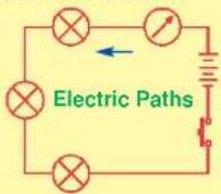
This diagram is a simplified drawing of the circuit, with the components represented by symbols (the symbols are explained on pages 4-6). Engineers use these diagrams, called schematics, because drawing pictures of their circuits takes too much time and the connections are often unclear.
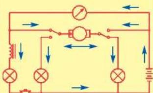
Electric Paths

Project #2
PARALLEL PLAY

Assembly
Build the circuit as shown. Set the meter (M5) to the 5V scale.
Operation
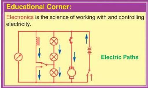
Set the right slide switch (S5) to "C" to turn on the circuit. The meter (M5) measures the voltage. The compass is attracted to the electromagnet (M3). The left slide switch (S5) can bypass the bottom lamp. Pushing the press switch (S2) will spin the fan.
Description
This circuit spreads the electricity from the batteries into four parallel sub-circuits to do different things. Connecting electrical components in parallel means they are between the same points in a circuit. You will learn about parallel circuits later.

WARNING: Moving parts. Do not touch the fan or motor during operation.
WARNING: Do not lean over the motor.

Project #3

Snappy says: switches are used all over electronics - try to count how many are in your home!

natural_image
Electrical circuit board setup with components like a battery, resistor, and LED (no visible text or symbols)
natural_image
Blue cartoon figure with number 2 standing on a yellow oval base (no text or symbols)WICKED SWITCHES
Assembly
Build the circuit as shown. Set the meter (M5) to the 1A scale.
Operation
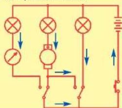
Push the press switch (S2) to turn on the circuit. Flip the slide switches (S5) and see what happens. You may need to give the fan a push with your finger to get it started.
Description
The slide switches direct the electricity between the different circuit paths (each has a lamp). You will learn more about switches later.

WARNING: Moving parts. Do not touch the fan or motor during operation.

WARNING: Do not lean over the motor.
Educational Corner:
Switches are used to turn electrical appliances on or off, or to change electrical connections.
The light in your refrigerator is activated by a switch. Each of the buttons on your computer keyboard controls a switch, and there are several switches in the computer's mouse.
Electric Paths

Project #4

SPINNING CYLINDER SUSPENDER
Assembly
Build the circuit as shown. Set the meter (M5) to the 1A scale. Drop the thin rod into the electromagnet.
Operation
Set the right slide switch (S5) to "C" to turn on the circuit. The thin rod gets suspended in mid-air by the electromagnet. The left slide switch (S5) selects whether the lamps or motor are on.
Description
The thin rod is held in the air by electromagnetism, which you will learn more about later.


Project #5

natural_image
Illustration of a hand washing clothes inside a washing machine (no text or symbols)Find some clothes that cling together in the dryer, and try to uncling them.
ELECTRICITY YOU CAN WEAR

natural_image
Close-up of a human hand resting on a dark surface, no visible text or symbolsRub a sweater (wool is best) and see how it clings to other clothes.

natural_image
Close-up of a person's torso with visible hair and dark clothing, no text or symbols presentThe crackling noise you hear when taking off a sweater is static electricity. You may see sparks when taking one off in a dark room.
Educational Corner:
Did you ever wonder why clothes cling together when they come out of the dryer? Did you ever hear a crackling sound when you take off a sweater? (If the room is dark you might even see sparks.) Did you ever feel a "zap" when you touch someone wearing a sweater on a dry day? These effects are caused by electricity. We call this static electricity because the electrical charges are not moving, although pulling clothes apart sounds like static on a radio. When electricity is moving (usually through wires) to do something in another place, we call it an electric current.
Electricity is an attraction and repulsion of particles in a material. All materials are made up of atoms, which are really, really tiny. Atoms have a nucleus (which has positive electrical charges), which is surrounded by tiny electrons (negative electrical charges). When you rub a material, electrons can move on or off the atoms, giving them an electrical charge.
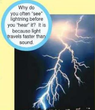
Photo courtesy of: NOAA Photo Library, NOAA Central Library; OAR/ERL/National Severe Storms Laboratory (NSSL) [via pingnews].
Electricity exists everywhere, but is so well balanced, that you seldom notice it. But, sometimes differences in electrical charges build up between materials, and sparks can fly. Lightning is the same effect as the sparks between clothes, but on a much greater scale. A cloud holds static electricity just like a sweater.

This diagram shows the structure of an atom, except that the nucleus and electrons are actually much farther apart.
Note: This project works best on a cold dry day. If the weather is humid, the water vapor in the air allows the static electric charge to dissipate, and this project may not work.


Project #6
ELECTRICITY IN YOUR HAIR

Assembly
You need a comb (or a plastic ruler) and some paper for this project. Rip up the paper into small pieces.
Operation
Run the comb through your hair several times then hold it near the paper pieces to pick them up. You can also use a pen or plastic ruler, rub it on your clothes (wool works best).
Description
Rubbing the comb through your hair pulls extremely tiny charged particles from your hair onto the comb. These give the comb a static electrical charge, which attracts the paper pieces.
Educational Corner:

natural_image
Close-up of a hand holding a small black comb, with a purple circular frame highlighting the object (no text or symbols visible)Iron filings are weakly attracted to the comb.
Iron filings are strongly attracted to the magnet.

natural_image
Hand applying red paint to a white surface, enclosed in a purple circular frame (no text or symbols visible)Do you want to learn more?
Hold your magnet near the paper pieces; nothing happens.
Run the comb in your hair again and place it next to the iron filings case; not much happens (there may be a weak attraction). Now hold the magnet near the iron filings; they jump to it easily.
What's happening?
Running the comb through your hair builds up an electric charge in it, which is different from the magnetic charge in the magnet. The paper pieces are attracted to an electric charge, while the iron filings are attracted to a magnetic charge.
You will learn more about the differences between electricity and magnetism later.
Snappy says: notice how your hair can "stand up" or be attracted to the comb when the air is dry. Wetting your hair dissipates the static charge.

natural_image
Blue stick figure with numbered limbs and a yellow oval base (no text or symbols)
Project #7
BENDING WATER

natural_image
Two circular images showing a person brushing their hair and a kitchen sink with a tool (no text or symbols visible)Assembly
You need a comb (or plastic ruler) and a water faucet for this project.
Operation
Run the comb through your hair several times then hold it next to a slow, thin stream of water from a faucet. The water will bend towards it. You can also use a plastic ruler. Rub it on your clothes (wool works best).
Description
Rubbing the comb through your hair builds up a static electrical charge on it, which attracts the water.
Educational Corner:
Static electricity was discovered more than 2,500 years ago when the Greek philosopher Thales noticed that when amber (a hard, clear, yellow-tinted material) is rubbed, light materials like feathers stick to it. Electricity is named after the Greek word for amber, which is electron.
Other facts about Static Electricity:
- Static electricity in the atmosphere causes the "static" (erratic noises) you hear on your AM radio when reception is poor.
- Static Electricity can damage some types of sensitive electronic components. Electronics manufacturers protect against this using static-dissipating wrist straps, floor mats, and humidity control. Your Snaptricity® parts will not be damaged by static.
- Some homes have "lightning rods", which are metal bars from the roof to the ground. These help protect the home by encouraging lightning to go through the the rods instead of the house.

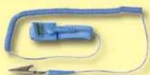
Anti-Static Wrist Strap

Lightning Rod
Note: This project works best on a cold dry day. If the weather is humid, the water vapor in the air allows the static electric charge to dissipate, and this project may not work.
Snappy says: big planes can build up a large static charge in flight. They are usually connected to something like a lightning rod as soon as they land.

natural_image
Blue cartoon stick figure with numbered limbs and a smiling face, set against a yellow background (no text or symbols)
Project #8
Note: This project works best on a cold dry day. If the weather is humid, the water vapor in the air allows the static electric charge to dissipate, and this project may not work.
MORE STATIC TRICKS

natural_image
Close-up of a hand holding a white strip next to a yellow background, with no visible text or symbols.Take a piece of newspaper or other thin paper and rub it vigorously with a sweater or pencil. It will stick to a wall.

natural_image
Close-up of hands holding a white tool, with another hand holding a white cable against a yellow background (no text or symbols visible)Cut the paper into two long strips, rub them, then hang them next to each other. See if they attract or repel each other.

natural_image
Two balloons, one orange and one blue, held together against a yellow background (no text or symbols)If you have two balloons, rub them to a sweater and then hang the rubbed sides next to each other. They repel away. You could also use the balloons to pick up tiny pieces of paper.

Educational Corner:
Electricity vs. Gravity:
Electricity is immensely more powerful than gravity (gravity is what causes things to fall to the ground when you drop them). However electrical attraction is so completely balanced out that you don't notice it, while gravity's effects are always apparent because they are not balanced out.
Gravity is actually the attraction between objects due to their weight (or technically, their mass). This effect is extremely small and can be ignored unless one of the objects is as big as a planet (like the earth). Gravity attraction never goes away and is seen every time you drop something. Electrical charge, though usually balanced out perfectly, can move around and change quickly.
For example, you have seen how clothes can cling together in the dryer due to static electricity. There is also a gravity attraction between the sweaters, but it is always extremely small.

natural_image
Illustration of two figures: a superhero lifting a barbell and a bald man lifting a dumbbell (no text or symbols)Electricity Gravity
In many photocopiers, a drum is charged with static electricity. Light from the white areas of the document being copied destroys the charge, but dark areas of the document leave a pattern of charge on the drum. Toner (a powder) is attracted to the charged areas, creating an image. The toner is then transferred to paper and melted on.
-
Light from white areas of document being copied destroys the charge.
-
Corona wire charges drum with static electricity

-
Toner from roller is attracted to the charged areas.
-
Toner image transfers to charged paper.

Project #9
LIGHT THE WAY

Assembly
Build the circuit shown by placing all the parts with a black 1 next to them on the clear plastic base grid first. Then, assemble parts marked with a 2. Screw a bulb into the lamp socket (L4) and install three (3) "AA" batteries (not included) into the battery holder (B3).
Operation
This circuit is just like a lamp in your home, when you flip the switch (S5) to on (position B), the lamp (L4) will be on.

natural_image
Electronic circuit board with components including resistors, capacitors, and a battery (no visible text or symbols)Educational Corner:
What is really happening here?
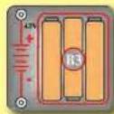
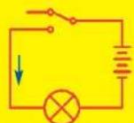
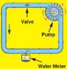
- The batteries (B3) convert chemical energy into electrical energy and "push" it through the circuit, just like the electricity from your power company. A battery pushes electricity through a circuit just like a pump pushes water through a pipe.


- The snap wires (the blue pieces) carry the electricity around the circuit, just like wires carry electricity around your home. Wires carry electricity just like pipes carry water.

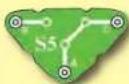
- The slide switch (S5) controls the electricity by turning it on or off, just like a light switch on the wall of your home. A switch controls electricity like a faucet controls water.

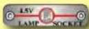
- The lamp (L4) converts electrical energy into light, it is the same as a lamp in your home except smaller. In a light bulb, electricity heats up a high-resistance wire until it glows. A light bulb shows how much electricity is flowing in a circuit like a water meter shows how fast water flows in a pipe.


- The base grid is a platform for mounting the circuit, just like how wires are mounted in the walls of your home to control the lights.

Comparing Electric Flow to Water Flow:
Electric Paths
Snappy says: touch the light and feel how warm it is. Only about 5% of the electricity is converted into light, the rest becomes heat. Don't touch light bulbs in your home because they can be very hot.

Project #10
FLIP IT

Assembly
Build the circuit shown.
Operation
The slide switch (S5) directs the electricity to either of two paths (both lamps here). It is like many switches in your home, controlling different lights in the same area.
Variant
Replace the 3-snap wire with the press switch (S2). Now either lamp (L4) is only on when S2 is pressed.
Educational Corner:
The slide and press switches included in Snaptricity® are simple switches, more complex types are also available. Switches come in almost every shape and size imaginable. There are membrane, rocker, rotary, DIP, push button, and momentary types just to name a few.

Very often, a single switch is used to make many different connections. The combinations of connections for a switch are indicated in the symbol for it. Here are some examples:


The "on" position of a switch is also called the "closed" position. Similarly, the "off" position is also called the "open" position. This is because the symbol for a slide switch is similar to the symbol for a door in an architect's drawing of a room:

The electronics symbol for a slide switch should be thought of as a door to a circuit, which swings open when the switch is off. The "door" to the circuit is closed when the switch is on. This is shown here:


Project #11

Snappy says: the battery voltage drops when the lamp is connected because the batteries have trouble supplying as much electricity as the lamp would like. Remember that a battery produces electricity from a chemical reaction. Not only is there a limited amount of the chemicals in a small battery (batteries slowly get weaker as you use them), but also not all of the material can react together at the same time.
natural_image
Illustration of a blue robotic arm with numbered joints and a smiling face (no text or symbols)
natural_image
Electronic circuit board with components and a 5V power indicator (no readable text or symbols)PUSHING ELECTRICITY
Assembly
Build the circuit and connect the red jumper wire as shown. Set the meter (M5) to the 5V setting and the slide switch (S5) to position C at first.
Operation
Read the battery voltage on the meter (the top scale), it should be about 4.5V. The lamp will be off.
Flip the switch to position B; the lamp lights and the voltage drops a little. (To learn why the voltage drops now, ask Snappy.)
Move the red jumper wire from position A on the switch to position B. The battery voltage is the same here because none is lost across the switch.
Now flip the switch to position C (OFF); the voltage at the lamp drops to zero and it shuts off.
Educational Corner:
Electricity is the movement of sub-atomic charged particles (electrons) through a material due to electrical pressure across the material, such as from a battery.
The electrical pressure exerted by a battery or other power source is called voltage and is measured in volts (V. and named after Alessandro Volta who invented the battery in 1800). Notice the "+" and "-" signs on the battery. These indicate which direction the battery will "pump" the electricity.
Circuits need the right voltage to work properly. For example, if the electrical pressure to a lamp is too low, then the bulb won't turn on; and if too high, then the bulb will overheat and burn out. The electric current is a measure of how fast electricity is flowing in a wire, just as the water current describes how fast water is flowing in a pipe. It is expressed in amperes (A, named after Andre Ampere who studied the relationship between electricity and magnetism) or milliamps (mA, 1/1000 of an ampere).
Record the voltage you measured here, it will be used in project 13:

Project #12
PUSHING A LOT OF ELECTRICITY

Assembly
Build the circuit as shown; it is the same as the preceding one except the lamp (L4) was replaced by the motor (M1). Set the meter (M5) to the 5V setting and the slide switch (S5) to position C at first.
Operation
Read the battery voltage on the meter (the top scale), it should be about 4.5V. Flip the switch to position B; the fan spins and the voltage drops - more than it did with the lamp.
Turn off the circuit and remove the fan. Turn the switch back on and read the voltage; it doesn't drop as much without the fan.
Description
It takes a lot of current to spin the fan as fast as it would like to go, and the batteries can't produce enough. As a result, the voltage (electrical pressure) from the batteries drops.
It's a lot easier to spin the motor shaft without the fan on it, so the voltage doesn't drop much without the fan.

Educational Corner:
Wires can generally be as long as desired without affecting performance, just as using garden hoses of different lengths has little effect on the water pressure as you water your garden. However there are cases where the length and size of a pipe does matter, such as in the water lines for your city. Similarly, wire length and size are important for electric power lines transporting electricity from a power plant in a remote area to a city.
Batteries are made from materials like zinc and magnesium dioxide, electricity flows as these react with each other. As more material is used up by the reaction, the battery voltage is slowly reduced until eventually the circuit no longer functions and you have to replace the batteries. Some batteries, called rechargeable batteries (such as the batteries in your cell phone), allow you to reverse the
chemical reaction using another electric source.

Project #13

Snappy says: the symbol is the last letter in the Greek alphabet and is pronounced Omega.

natural_image
Electronic circuit board with components and a numbered label (1A), no readable text or symbols on the main subject.WHAT'S AN OHM?
Assembly
Build the circuit shown. Set the meter (M5) to the 1A setting.
Operation
Set the slide switch (S5) to position B to measure the current through the lamp (L4).
Educational Corner:
The resistance of a circuit represents how much it resists the electrical pressure (voltage) and limits the flow of electric current. The relationship between voltage, current, and resistance is the most important one in electronics. It is known as Ohm's Law (after George Ohm who discovered it in 1828):
$$ \text { Current } = \frac {\text { Voltage }}{\text { Resistance }} $$
When there is more resistance, less current will flow unless you increase the voltage. Resistance is measured in ohms. The symbol used for an ohm is .
Using the voltage measurement you made in project 11 and the current measurement you made here, you can calculate the resistance of the lamp. It is usually 15-20 ohms.
The other parts in the circuit (switch, meter on 1A scale, blue snap wires, and batteries) also have resistance but these are much smaller.
Note: Your actual results may vary. Your M5 meter is a simple meter; don't expect it to be as accurate as normal electronic test instruments.
What is Resistance? Take your hands and rub them together very fast. Your hands should feel warm. The friction between your hands converts your effort into heat. Resistance is the electrical friction between an electric current and the material it is flowing through; it is the loss of energy from electrons as they move through the material.
The "power" of electricity is a measure of how fast energy is moving through a wire. It is expressed in Watts (W, after James Watt for his work with engines). It is a combination of the electrical voltage (pressure) and current:
$$ \text { Power } = \text { Voltage } \times \text { Current } $$
$$ O R $$
$$ \text { Power } = \frac {\text { Voltage } \times \text { Voltage }}{\text { Resistance }} $$
= Current x Current x Resistance
Using the voltage and current measurements you made, you can calculate the power of the lamp. It should be about 1 watt. Compare this to the light bulbs in your home, which are usually about 40-100 watts.
Electric Paths


Project #14
BE A SCIENTIST

Snappy says: the best conductor ever discovered is silver, which is very expensive. Copper is the second best conductor, and it is used in almost all electrical wires.

natural_image
Cartoon-style blue stick figure with numbered joints and a smiling face, set against a yellow background (no text or symbols)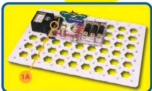
natural_image
Electronic circuit board with hexagonal grid pattern and component, no visible text or symbolsAssembly
Build the circuit shown, the ? can be anything you want. Set the meter (M5) to the 1A setting.
Operation
Turn on the slide switch (S5, position B) and touch various materials between the snaps on the switch and meter. See which materials are good at transporting electricity by watching the meter current and lamp (L4) brightness. Try string, the electrodes, a shirt, plastic, paper, two of your fingers, wood, or anything in your home.
If the meter reads zero, switch it to the 1mA setting to see if there is just a very small current. To help protect the meter, always switch back to the 1A scale before testing a new circuit.
Educational Corner:
Some materials, such as metals, have very low resistance to electricity will make the lamp bright and give a large current measurement on the meter. These materials are called conductors. Conductors have electrons that are loosely held to the nucleus and can move easily.
Other materials, such as paper, air, and plastic, have very high resistance to electricity. These will turn off the lamp and give a zero current measurement on the meter even in the 1mA setting. These materials are called insulators. Insulators have their electrons locked in tight and have no room for more.
Did you ever hear the term "blown fuse"? Some special wires are designed to break when an unexpectedly high current flows through them. These are called fuses.
This wire melts to break the circuit.

Fuses are designed to shut down a circuit when something is wrong, such as a component failure, bad design, or a person using it improperly. This shutdown prevents further damage to the circuit, and can prevent explosions or fires.
Fuses are important for safety and most electrical products have one, especially if they use electricity supplied by your local electric company. Small battery-powered products usually do not have them because the batteries are not powerful enough to cause harm.
Some fuses need to be replaced after they
"blow", but other can be reset by flipping a switch. Every home has an electrical box of resetable fuses, it may look like this:


Project #15


natural_image
Electronic circuit board setup with battery, switch, and power cord (no text or symbols visible)MAKE YOUR OWN PARTS
Assembly
Build the circuit shown, set the meter (M5) to the 1mA setting.
Operation
Make your parts using either the water puddles method (A), the drawn parts method (B), or the pencil parts method (C). Set the slide switch (S5) to position B to turn on the circuit. Touch the metal in the jumper wires to your parts and read the current in milliamps.
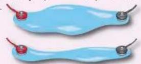
Method A (easy): Spread some water on the table into puddles of different shapes, perhaps like the ones shown below. Touch the jumper wires to points at the ends of the puddles.
Method B (challenging): Use a SHARP pencil (No. 2 lead is best) and draw shapes, such as the ones here. Draw them on a hard, flat surface. Press hard and fill in several times until you have a thick, even layer of pencil lead. Touch the jumper wires to points at the ends of the drawings. You may get better electrical contact if you wet the metal with a few drops of water. Wash your hands when finished.
Method C (adult supervision and permission required): Change the setting on the meter to the 1A scale. Use some double-sided pencils if available, or VERY CAREFULLY break some pencils in half. Touch the jumper wires to the black core of the pencil at both ends.

natural_image
Close-up of two hands holding a yellow pencil and black eraser, no text or symbols visibleEducational Corner:
You can use Ohm's Law to measure the resistance of your puddles and drawings. The voltage is about 4.5V, and use the current measured on the meter.
Resistance =
The black core of pencils is graphite, the same material used in resistor components throughout the electronics industry.
Snappy says: long narrow shapes have more resistance than short wide ones.

natural_image
Blue stick figure with number 1 at top, arms labeled 2, and legs marked 3 (no text or symbols beyond numbers)□ Project #16

natural_image
Electrical circuit setup with battery, switch, and power supply on a perforated base (no text or symbols visible)HYDRO-RESISTORS
Assembly
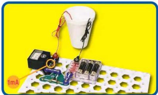
Build the circuit shown. Set the meter (M5) to the 1mA setting. Add about 1/4 inch of water to a cup or bowl. Connect the jumper wires and place them in the water, make sure the metal parts aren't touching each other. Set the slide switch (S5) to position B to turn the circuit on.
Operation
Measure the current through the water.
Add salt to the water and stir to dissolve it. The current should be higher now (if not already at full scale), since salt water has less resistance than plain water.
Now add more water to the cup and watch the current.
If you have some distilled water, place the jumper wires in it and measure the current. You should measure close to zero current, since distilled (pure) water has very high resistance. Normal water has impurities which lower its resistance. Now add salt to the distilled water and watch the current increase as the salt dissolves!
You can also measure the current through other liquids.
Don't drink any water or liquids used here.
Educational Corner:
Depending on your local water supply, your current measurement may exceed the 1mA scale. You can switch the meter to the 5V scale to get a better comparison, though it isn't really a voltage measurement.
In the 5V setting, the water resistance is compared to the internal resistance of the meter. A low reading means the water has relatively high resistance. A high reading of 4V or more means the water has relatively low resistance.

Project #17

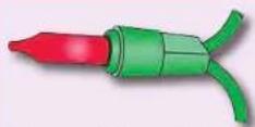
Strings of Christmas lights are little low-voltage lamps connected in series to the house power (120V). They are inexpensive, but if one bulb falls out, then the entire string will be off.
Most strings will still work if one bulb burns out because a special heat-activated bypass wire is built into each bulb. When the bulb burns out, the full house voltage is across the bypass wire, which heats it until it turns on. Sometimes only half the bulbs in a string are lit. This is because some long strings are actually two (or more) shorter strings connected in parallel.

natural_image
Electronic circuit board with hexagonal grid pattern and terminal blocks (no visible text or symbols)ONE WAY AROUND
Assembly
Build the circuit and push the press switch (S2). The lamps (L4) are all on, but are dim.
Description
The three lamps are connected in a series. They are dim because the voltage from the batteries (B3) is divided between them.
Educational Corner:
Connecting parts in series is one way of arranging them in a circuit. The advantage of it is that wiring them together is simple. The disadvantage is that if one lamp breaks, all three will be off.
In this circuit the lamps are the resistances which are limiting the flow of electricity. Placing resistances in series increases the total resistance. Advanced users can compute the total resistance as follows:
$$ R _ {\text { series }} = R 1 + R 2 + R 3 + \dots $$
The current is the same through all the resistances in a series circuit. Ohm's Law says that Voltage equals Current times Resistance, so the highest resistances in a series circuit will have the largest voltage drop across them. Equal resistances will have the same voltage drop. In other words:
Voltage [across one resistor] = [of that resistor]Resistance [of a series in the circuit] x Voltage (load applied to the series circuit)
Snappy says: the 0V or “—” side of the battery is often referred to as “ground”, since in house or building wiring it is connected to a rod in the ground as protection against lightning.

natural_image
Blue stick figure with numbered limbs and a smiling face, set against a yellow background (no text or symbols)Electric Paths


Project #18
MANY PATHS

flowchart
graph TD
    A["Component A"] -->|1| B["Component B"]
    B -->|2| C["Component C"]
    C -->|4V LAMP| D["Component D"]
    D -->|2| E["Component E"]
    E -->|5| F["Component F"]
    F -->|1| G["Component G"]
    G -->|2| H["Component H"]
    H -->|1| I["Component I"]
    I -->|5| J["Component J"]
    J -->|1| K["Component K"]
    K -->|2| L["Component L"]
    L -->|1| M["Component M"]
    M -->|5| N["Component N"]
    N -->|1| O["Component O"]
    O -->|2| P["Component P"]
    P -->|1| Q["Component Q"]
    Q -->|5| R["Component R"]
    R -->|1| S["Component S"]
    S -->|2| T["Component T"]
    T -->|1| U["Component U"]
    U -->|5| V["Component V"]
    V -->|1| W["Component W"]
    W -->|2| X["Component X"]
    X -->|1| Y["Component Y"]
    Y -->|5| Z["Component Z"]
    Z -->|1| AA["Component AA"]
    AA -->|2| AB["Component AB"]
    AB -->|1| AC["Component AC"]
    AC -->|5| AD["Component AD"]

natural_image
White hexagonal grid board with purple and pink components, no visible text or symbolsAssembly
Build the circuit and push the press switch (S2). The lamps (L4) are all bright.
Description
The three lamps are connected in parallel with one another. They are bright because each lamp gets the full battery voltage. The voltage pushes the current with equal force, because all are 4.5V, down each path.
Educational Corner:
Connecting parts in parallel is another way of arranging them in a circuit. The advantage of it is that if one burns out, the others will still work (unscrew one of the bulbs to prove this). The disadvantage is that wiring the parts together is more complex than with series circuits.
All large circuits are made of combinations of series and parallel circuits.
In this circuit the lamps are the resistances which are limiting the flow of electricity. Placing resistances in parallel decreases the total resistance. Advanced users can compute the total resistance as follows:
The voltage is the same across all the resistances in a parallel circuit. Ohm's Law says that Voltage equals Current times Resistance, so the lowest resistances in a parallel circuit will have the most current through them. Equal resistances will have the same current. In other words: Resistance
Current (through one branch) = (total in all OTHER parallel branches)Resistance × Current (total at resistors in all branches)
Electric Paths


Project #19

flowchart
graph TD
    A["Control Unit"] --> B["Step 1"]
    B --> C["Step 2"]
    C --> D["Step 3"]
    D --> E["Step 4"]
    E --> F["Step 5"]
    F --> G["Feedback Loop"]
    G --> H["Step 6"]
    H --> I["Step 7"]
    I --> J["Step 8"]
    J --> K["Step 9"]
    K --> L["Step 10"]
    L --> M["Step 11"]
    M --> N["Step 12"]
    N --> O["Step 13"]
    O --> P["Step 14"]
    P --> Q["Step 15"]
    Q --> R["Step 16"]
    R --> S["Step 17"]
    S --> T["Step 18"]
    T --> U["Step 19"]
    U --> V["Step 20"]

natural_image
Electrical circuit setup with a 5V power supply and a battery pack on a grid-lined board (no text or symbols visible)
PARALLEL SWAPPING
Assembly
Build the main circuit and set the meter (M5) on the 5V setting.
Operation
Push the press switch (S2); the lamp lights (L4) and the meter (M5) measures the voltage from the batteries (B3).
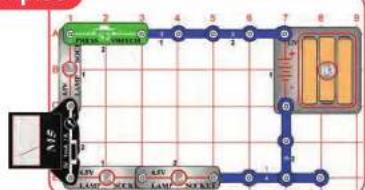
Part B: move the meter so it's across location "B" and then location "C". Measure the voltage at each location, it should be the same.
Part C: swap the locations of the meter and lamp. The meter should still measure the same voltage.
Description
This circuit shows that rearranging parts that are connected in parallel does not change the circuit, because the meter measured the same voltage for each arrangement.
Educational Corner:
The choice of whether to use a series or parallel configuration in a circuit depends on the application, but will usually be obvious. For example the overhead lights in the rooms of your
home are all connected in parallel so that you can have lights on in some rooms and off in others, but within each room the light and switch are connected in series so the switch can control the light.
Electric Paths

natural_image
Simple electrical circuit diagram with two bulbs, a variable resistor, and a car (no text or symbols)

Examples

flowchart
graph TD
    A["Terminal A"] -->|1| B["Switch"]
    B -->|2| C["Lamp"]
    C -->|3| D["Socket"]
    D -->|4| E["Terminal B"]
    E -->|5| F["Lamp"]
    F -->|6| G["Socket"]
    G -->|7| H["Terminal H"]
    H -->|8| I["Terminal I"]
    I -->|9| J["Terminal J"]
    J --> K["Terminal K"]
    K --> L["Terminal L"]
    L --> M["Terminal M"]
    M --> N["Terminal N"]
    N --> O["Terminal O"]
    O --> P["Terminal P"]
    P --> Q["Terminal Q"]
    Q --> R["Terminal R"]
    R --> S["Terminal S"]
    S --> T["Terminal T"]
    T --> U["Terminal U"]
    U --> V["Terminal V"]
    V --> W["Terminal W"]
    W --> X["Terminal X"]
    X --> Y["Terminal Y"]
    Y --> Z["Terminal Z"]
flowchart
graph TD
    A["Light Lamp"] --> B["Lamp 1"]
    B --> C["Lamp 2"]
    C --> D["Lamp 3"]
    D --> E["Lamp 4"]
    E --> F["Lamp 5"]
    F --> G["Lamp 6"]
    G --> H["Lamp 7"]
    H --> I["Lamp 8"]
    I --> J["Lamp 9"]
    J --> K["Lamp 10"]
    K --> L["Lamp 11"]
    L --> M["Lamp 12"]
    M --> N["Lamp 13"]
    N --> O["Lamp 14"]
    O --> P["Lamp 15"]
    P --> Q["Lamp 16"]
    Q --> R["Lamp 17"]
    R --> S["Lamp 18"]
    S --> T["Lamp 19"]
    T --> U["Lamp 20"]
    U --> V["Lamp 21"]
    V --> W["Lamp 22"]
    W --> X["Lamp 23"]
    X --> Y["Lamp 24"]
    Y --> Z["Lamp 25"]
Snappy says: In the first moment after you press the switch, the meter will show a higher "surge" current. Light bulbs have less resistance when you first turn them on, then increase resistance as they get bright.

natural_image
Electronic circuit board with components and a labeled component (no readable text or symbols)
natural_image
Blue cartoon figure with numbered limbs and a yellow base, no text or symbols presentSERIES SWAPPING
Assembly
Build the main circuit and set the meter (M5) on the 1A setting.
Operation
Push the press switch (S2); the lamps (L4) light and the meter (M5) measures the current through the circuit.
Now swap the positions of any of the lamps, 3-snap wires, the press switch and the meter (the meter should always be placed so it hangs out of the circuit). Read the current on the meter, it should be the same however the parts are arranged.
Note: Your M5 meter is a simple meter. It may read zero on this scale even though a small current is flowing.
Description
This circuit shows that rearranging parts that are connected in series does not change the circuit, because the meter measured the same current for each arrangement.
Educational Corner:
Which way does electricity really flow? In the Electric Paths drawings (schematics), electricity is shown flowing from the "+" battery terminal, through the circuit, and back to the "-" battery terminal. This is how electricity was presumed to flow beginning with discoveries by Benjamin Franklin in 1747. Later discoveries in sub-atomic physics showed that the charged particles that were moving (electrons) had a "-" charge, and that they were
moving from “-” to “+” charged materials.
However, understanding circuits is easier if you assume electricity flows from "+" to "−", and all circuit analysis is done this way.

Project #21
LIGHT BULB
Snappy says: most of the electrical energy used by these bulbs becomes heat, not light.

natural_image
Blue stick figure with numbered joints and a smiling face, standing on a yellow oval background (no text or symbols)
natural_image
White electronic circuit board with hexagonal grid pattern and a small component on top, set against a solid yellow background (no text or symbols visible)Operation
Build the circuit and hold down the button on the press switch (S2). Two lamps (L4) are very dim while one is bright.
Description
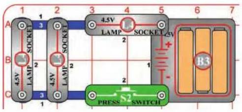
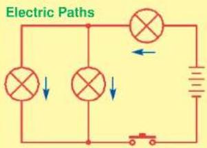
All the electric current flows through the top lamp, then divides between the two lamps on the left. The top lamp is much brighter than the others because it has twice as much electricity flowing through it.
Educational Corner:
Why is the top lamp so much brighter than the others, even though it only has twice as much electricity through it? And why do the left bulbs take a few seconds before they make any light?
Incandescent bulbs like these make light by passing a big electric current through a special high-resistance wire, the filament, which gets so hot that it glows. The left bulbs get less current than the top one so they take longer to heat up and don't get as hot.
Do you want to learn more?
Incandescent bulbs produce lots of heat, and the glass bulb prevents the filament from reacting with oxygen in the air and burning. When the voltage rating of an incandescent bulb is exceeded, the filament gets so hot it burns out. Filaments are usually made of tungsten, since ordinary copper would melt.
The fluorescent light bulbs that come in white 4 ft. tubes are the standard room lights for offices and schools. They pass electric current through a gas, usually argon. This gas emits light as the electricity passes through it, similar to how a tungsten wire does. Although larger and more expensive than ordinary incandescent lamps, they are typically five times more efficient at converting electricity into light.
The difference in heat produced between incandescent and fluorescent light bulbs might surprise you. Find a fluorescent bulb and feel the heat coming off it; you won't feel much. Find an incandescent lamp THAT HAS BEEN OFF FOR A WHILE and turn it on. Feel the heat it produces; it soon becomes too hot to touch. Only about 5% of the electricity used by incandescent bulbs is converted into light. Without the more efficient fluorescent bulbs, our society of office buildings might have been much different.

Project #22

Snappy says: you can also connect the black jumper wire to the 3-snap wire, then touch the red and black jumper wires across the terminals of any low voltage battery to measure it, or just use the meter with the jumper wires connected to it.

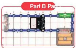
Part B

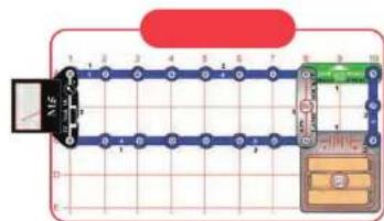
Part C

BATTERIES IN SERIES
Assembly
Build the circuit as shown and set the meter (M5) to the 5V setting.
Operation
A. Read the voltage on the meter. If your batteries are new then it should be about 4.5V.
B. Remove the left battery in the holder (B3) and move the end of the red jumper wire to touch the left spring in the holder. Read the voltage on the meter; measuring 2 batteries.
C. Now also remove the center battery and move the end of the red jumper wire to touch the center spring in the holder. Read the voltage on the meter; measuring 1 battery.
NOTE: The accuracy of your meter may vary.
Description
When batteries are connected in series, they add together, making the total voltage higher.

natural_image
Electronic circuit board with 5V power supply and connected components (no readable text or symbols)Educational Corner:
Part A: Since the battery holder (B3) has three 1.5V type AA batteries in series, you should measure about 4.5V (1.5V + 1.5V + 1.5V = 4.5V).
Part B: Since you are measuring two 1.5V type AA batteries in series, you should measure about 3V (1.5V + 1.5V = 3V).
Part C: Since you are measuring one 1.5V type AA battery, you should measure about 1.5V.

Project #23
FOR ADVANCED USERS - ADULT SUPERVISION RECOMMENDED
BATTERIES IN PARALLEL


natural_image
Electrical circuit board setup with components including a breadboard, resistors, and a voltmeter (no visible text or symbols)
Assembly
Remove the center battery from the battery holder (B3). Build the circuit as shown. Set the meter (M5) to the 1A setting.
Operation
Touch the red or black jumper wires to the metal contacts for the center battery as shown. The bulbs (L4) will barely glow and the motor (M1) will probably need a push to get it started. The meter measures the current.
Touching both on at the same time connects both batteries in parallel. This makes the bulbs glow a little more, makes the motor spin faster, and increases the current on the meter.
Description
When batteries are connected in parallel they can supply more current to a circuit. This means more power.
Assembly
Remove parts from the circuit until it looks like the Part B drawing.
Operation
Touch the red or black jumper wires to the metal contacts for the center battery as shown. The single bulb (L4) will glow brighter than in the original circuit when only one battery is connected. Note: Your M5 meter is a simple meter. It may read zero on this scale even though a small current is flowing.
Description
Now connecting both batteries at once doesn't change the brightness or increase the current measured, because a single battery can supply as much current as this simple circuit needs.

Project #24

VOLTAGE DIVIDER
Assembly
Build the circuit shown. Place the meter (M5) on the 5V setting.
Operation
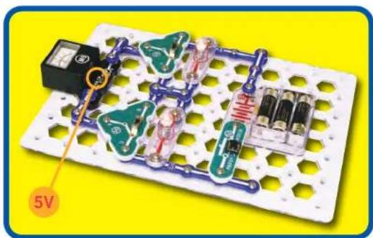
A. Set both slide switches (S5) to position B and push the press switch (S2). Both lamps (L4) light and the meter measures the voltage across the top one.
B. Set both slide switches to position C and push the press switch. Now the meter measures the voltage across the bottom lamp (it should be the same as for the top one).
C. Set the top slide switch to position B and the bottom switch to position C, then push the press switch. Now the meter measures the voltage across both lamps (it should be the individual lamp voltages added together).
Description
When equal components are placed in series, each having the same resistance to the flow of electricity, the total voltage will divide equally between them.
natural_image
Electronic circuit board with components and a 5V power indicator (no readable text or symbols)Educational Corner:
One of the most basic rules for analyzing circuits is Kirchhoff's Voltage Law (named after Gustav Kirchhoff, who stated it in 1847): the total voltage diving a circuit must equal the voltage drops within it.
This project proves it because the total voltage across both lamps equals the voltage from the batteries: (Vbatteries = Vlamp1 + Vlamp2)


Project #25
VOLTAGE SHIFTER

Assembly
Modify the preceding circuit into this one. Keep the meter (M5) on the 5V setting.
Operation
Both lamps (L4) are on and the meter shows the voltage across the top lamp, which is half the battery holder (B3) voltage.
Push the press switch (S2) to bypass the bottom lamp and remove it from the circuit. Now the top lamp is much brighter and the meter shows that the full battery voltage is across it.
natural_image
Electronic circuit board with components and a 5V power indicator (no readable text or symbols)Sometimes switches are pretty swift, they can sneak current around a lamp and make voltage shift.

natural_image
Blue stick figure with numbered limbs and a smiling face, standing on a yellow oval background (no text or symbols)Educational Corner:
Since the battery voltage driving the circuit is the same, bypassing the bottom lamp shifts all the voltage to the top lamp. This follows Kirchhoff's Voltage Law.
Electric Paths


Project #26
TRIPLE VOLTAGE DIVIDER
Assembly
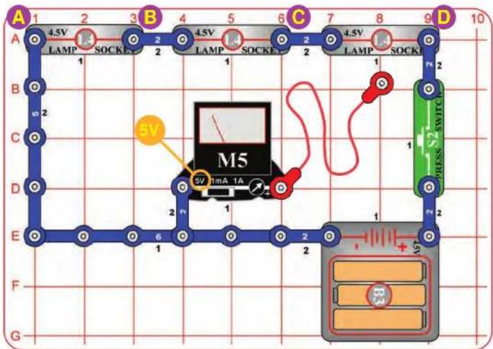
Build the circuit and set the meter (M5) on the 5V setting.
Operation
Snap the loose end of the red jumper wire to points A, B, C, or D. Push the press switch (S2) to measure the voltage at that point using the meter.
You can also connect the red jumper anywhere in the circuit to measure the voltage there.
Description
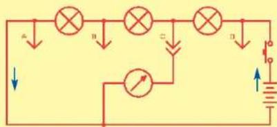
This circuit shows how the total voltage from the batteries gets divided among the components in the circuit, which are resisting the flow of electricity.

natural_image
Electrical circuit board with components including a 5V power supply and a battery, set on a grid of hexagonal holes (no readable text or symbols)Try to count how many batteries are in your home. Your count will probably be low. Many products that use your house power also have batteries to retain clock or programmed information during brief power outages (such as computers).
Educational Corner:
If a circuit is given too much voltage then its components will be damaged. It is like having the water in your faucet come out at higher pressure than you need, and it splashes all over the room. If water in a pipe is at too high of pressure then the pipe may burst.
Batteries can be selected to give a circuit just the voltage it needs. The electricity produced by your electric company comes at a higher voltage, which must be converted down for many circuits.
Electric Paths

Project #27
TRIPLE SWITCHING VOLTMETER
natural_image
Electrical circuit board setup with 5V power supply and components (no readable text or symbols)Assembly
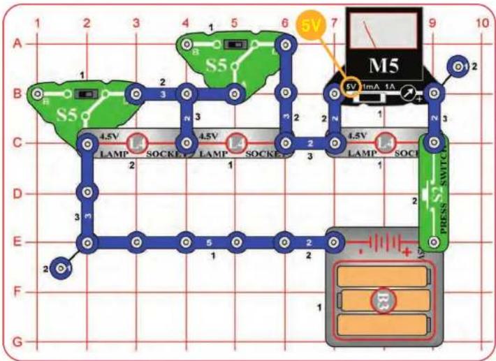
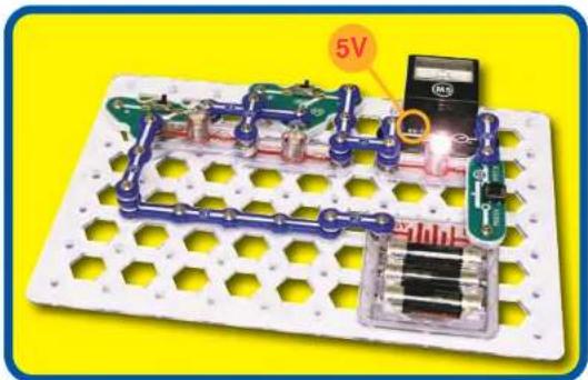
Build the circuit and set the meter (M5) on the 5V setting.
Operation
Set the slide switches (S5) to position C. Push the press switch (S2); the meter measures the voltage across the right lamp.
The slide switches control the left two lamps (L4), individually. If the lamps are on (switch position B), the battery voltage is split among them and less voltage will be measured across the right lamp.
Description
This is another example of how voltage divides as parts are added in series.
Educational Corner:
The lamps are acting as resistors, because they limit the flow of electricity in the circuit. As resistances are
added in series, they add together to reduce the current.


Project #28
TRIPLE SWITCHING AMMETER

Snappy says: switches come in many diverse forms. Try to count how many are in your home or car; you will be amazed. There are slide, press, membrane, rotary, push-button, and other switches controlling nearly everything.
natural_image
Labeled electronic circuit board with components and a small device (no readable text or symbols)
natural_image
Blue stick figure with numbered limbs and a smiling face, set against a yellow background (no text or symbols)Assembly
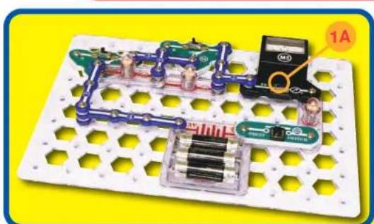
Build the circuit and set the meter (M5) on the 1A setting.
Operation
Set the slide switches (S5) to position C. Push the press switch (S2); the meter measures the current through the right lamp.
The slide switches control the left two lamps (L4), individually. If the lamps are on (switch position B), the battery voltage is split among them and less current will be measured through the lamps.
Note: Your M5 meter is a simple meter. It may read zero on this scale even though a small current is flowing.
Description
This is an example of how current decreases as parts are added in series.
When the slide switches are in position C, no current flows through the bypassed lamp because the switch has very low resistance.
Educational Corner:
Most electronic products have almost all of their components and wires mounted on special boards. In these boards, the "wires" connecting
parts are literally "printed" on the surface of the board; hence the boards all are called "printed circuit boards" or PCBs.

natural_image
Four electronic circuit boards with various components and wiring, arranged on a yellow background (no visible text or symbols)Electric Paths


Project #29



natural_image
Electrical circuit board with blue pipes and a 1A component, no visible text or symbols
CURRENT DIVIDER
Assembly
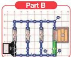
Build the main circuit and set the meter (M5) on the 1A setting.
Operation
Part A: Push the press switch (S2); the meter measures the current from the batteries (B3).
Part B: Swap the location of the meter with the 3-snap wire marked "B" ("+" side towards the lamp). Push the switch to measure the current through circuit branch "B".
Part C: Swap the "B" location of the meter with the "C" 3-snap. Push the switch to measure the current through the "C" branch.
Part D: Swap the "C" location of the meter with the "D" 3-snap. Push the switch to measure the current through the "D" branch.
Description
The current from the batteries splits up between the three lamps, because they are connected in parallel.
Educational Corner:
If you add up the current you measured through circuit branches B, C, and D, it should be the same as the current you measured from the batteries. (Your result may be a little different, because M5 is a simple meter with low accuracy.)
The total battery current here is much higher than in project 13, because this circuit has several lamps in parallel. The lamps are acting as resistors, limiting the flow of electricity in the circuit. As resistances are added in parallel, they increase the total current.
Kirchhoff's Current Law, an important rule for analyzing circuits, says that all current flowing into a point must flow out of it.
(Currentballeries = CurrentlampB + CurrentlampC + CurrentLampD)
Electric Paths
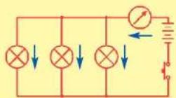

Project #30
FOR ADVANCED USERS - ADULT SUPERVISION RECOMMENDED
OHM'S LAW
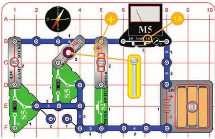

Educational Corner:
Since the battery voltage is 4.5V, you can use Ohm's Law to calculate the resistance of each part:
$$ \text { Resistance } = \frac {\text { Voltage }}{\text { Current }} = \frac {4 . 5 \mathrm{V}}{\text { Current }} $$
| Voltage Measured | Current Measured | Resistance Calculated | Typical Resistance | |
| Lamp 4.5 volts | 16 ohms | |||
| Electromagnet | 4.5 volts | 30 ohms | ||
| Motor (with fan) | 4.5 volts | 10 ohms | ||
| Motor (without fan) | 4.5 volts | 40 ohms |
Notes: Your actual results may vary. Unless your batteries are new, the voltage may be less than 4.5V. Also, your M5 meter is a simple meter. Don't expect it to be as accurate as normal electronic test instruments. In some cases, the meter may show zero current for the electromagnet; switch the meter to the 1mA scale to prove a current is flowing.
Another problem is that the battery voltage drops a little if the current is high. This drop may be 1-2 volts for the motor with fan. For some motors, typical resistance may be 3 ohms with fan and 20 ohms without fan.
Optional: For a more accurate resistance measurement, you can measure the actual voltage. Place the meter across the battery holder, set it to the 5V scale, and place a 3-snap wire where the meter used to be. Use the switches to measure the voltage for each part individually, as you did for the current.
Electric Paths

natural_image
Pure electrical circuit diagram with resistors, switches, and a battery (no text or symbols)Assembly
Build the circuit as shown (leave the fan off the motor (M1). Set the meter (M5) on the 1A setting, place the iron core rod into the electromagnet (M3), and both slide switches (S5) to the B position (off).
Operation
Set the left slide switch to position C to turn on the lamp (L4). The meter measures the electric current through the lamp.
Set the left switch back to B and set the right slide switch to position C. Now the meter measures the current through the electromagnet. The electromagnet will attract the compass needle.
Set the right slide switch back to B and push the press switch (S2). Now the meter measures the current through the motor.
Last, place the fan on the motor and measure its current with the fan on.
Description
By comparing the currents you measured, you can see which part has the most resistance to the flow of electricity.

WARNING: Moving parts. Do not touch the fan or motor during operation.

WARNING: Do not lean over the motor.

natural_image
Electrical circuit board with components including resistors, capacitors, and a battery (no visible text or symbols)
Project #31
OHM'S LAW - COLD LAMP


Educational Corner:
The current through the top lamp is split between the two lower lamps, so you would probably expect the lower lamps to be half as bright and to have half as much voltage across them. Instead, they are much dimmer and have a lot less voltage.
This happens because a dim light bulb has less resistance than a bright one! Your L4 light bulbs have resistance of less than 5 ohms when dim, and about 15 ohms when bright.
Resistance =

Assembly
The preceding circuit allowed you to calculate the resistance of the lamp (L4) by measuring the voltage and current. You did this while the lamp was bright, but the lamp has much lower resistance when it is dim.
Operation
Part A: Build the circuit at left and set the meter (M5) on the 5V setting. Push the press switch (S2) to measure the voltage across the top lamp, which is bright.
Part B: Move the meter so it is across base grid locations C2-E2. Push the press switch to measure the voltage across the lower lamps, which are very dim. Watch the lower lamps closely as you press the switch. Initially they are dark, but slowly become dimly lit.
Note: The voltage in Part B will be much smaller; in some cases it may even be too small to measure with your M5 meter. M5 is a simple meter, don't expect it to be as accurate as normal electronic test instruments.
Description
The top lamp turns on faster and brighter because it has a higher current through it, which heats up the filament quickly. The other lamps turn on slowly and dimly because they have half the current, which is barely enough to heat up their filaments.
Snappy says: when a large current flows through the lamp, the filament (a special high-resistance wire) heats up and glows. All wires have higher resistance when they are very hot.

natural_image
Cartoon illustration of a blue mechanical linkage with numbered joints and a smiling face (no text or symbols)
Project #32
2-WAY SWITCH

Snappy says: batteries are widely used because they are easy-to-use, safe, and portable.

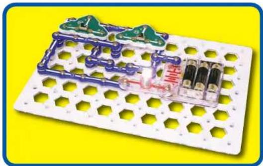
natural_image
White plastic electrical circuit board with blue and green components, set against a yellow background (no text or symbols visible)Assembly
Build the circuit as shown.
Operation
Whenever you flip either switch (S5), the lamp (L4) will change (turning on or off).
Description
This switch arrangement is used to control room lights in almost every home.
Educational Corner:
Example:
The lamp could be an overhead light in a hallway, and one slide switch would be at each end of the hallway. Whenever you walk into the hallway you flip the switch to turn on the light, and flip the other switch to turn off the light when you leave the hallway on the other side.
Electric Paths


Project #33
ANOTHER 2-WAY SWITCH
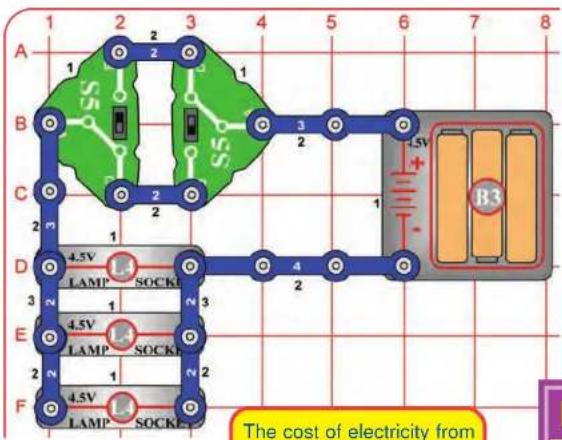
The cost of electricity from the electric company is much less than the cost of electricity from batteries.


natural_image
Electronic circuit board with integrated components and hexagonal grid pattern (no visible text or symbols)Assembly
Build the circuit as shown.
Operation
Whenever you flip either switch (S5), the lamp (L4) will change (turning on or off).
Description
This is another common switch arrangement used to control room lights in homes. It can be used to control many lights at the same time.
Educational Corner:
Only a tiny portion of the electricity used in our world comes from batteries. The rest is produced at enormous electric power plants, operated by your local electric company. The electricity from these power plants is available at each of the electrical outlets in the walls of your home. The voltage of this electricity is 120V, much higher than the voltage of the batteries in Snaptricity ^98 . The current available is very large, since it must power products like dishwashers and TVs.
Our lives are much easier and more fun by having such power available by simply plugging into an electrical outlet. This amount of electricity is also very dangerous, and it will kill anyone who abuses it. While accidents involving electricity are rare, they kill people every year. Never put anything into an electrical outlet except an electrical plug. Battery-powered products are safe, since small batteries are too weak to hurt people.
The protective plastic around the wires of a lamp plug are all that protects you from the full power of electricity. Damaged electrical cords should always be unplugged and repaired. Remember that electricity travels through water, so don't use electric products while taking a bath (battery-powered products are fine).
Your home has fuses that automatically turn off the electricity in your home if there is an electrical problem, such as a short circuit. These fuses prevent electrical problems in your home from affecting your neighbors, but they do not protect you.
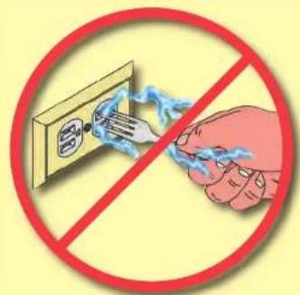
Electric Paths


Project #34
3-SPEED MOTOR


WARNING: Moving parts. Do not touch the fan or motor during operation.
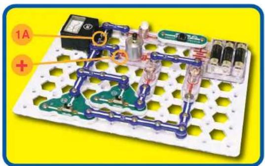
Assembly
Build the circuit. Set the meter (M5) to the 1A scale and leave the fan off the motor (M1).
Operation
Push the press switch (S2) to turn on the motor and use the slide switches (S5) to control its speed. The meter (M5) measures the current. You may need to give the motor a push to get it started, but do not touch it while it is spinning.
Description
Here you control the motor speed by diverting some of the current to the lamps.
Educational Corner:
Do you want to learn more?
Friction
Place the fan on the motor. Set both slide switches to position B and push the press switch. The motor will not spin.
Now set the slide switches to position C, push S2 to get the motor spinning, then set the slide switches back to B. The motor could not start spinning with the other lamps on, but it will keep spinning as long as you keep pushing S2. Why?
The surfaces touched by the motor shaft offer some resistance to motion, called friction. Once the initial friction is overcome, it doesn't take much effort to keep the motor spinning.
Motor performance may vary, in rare cases it may spin in all switch settings.

Electric Paths

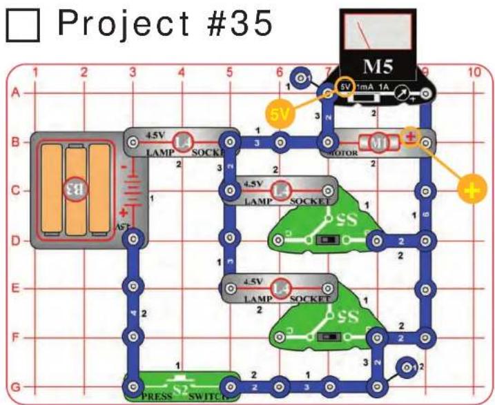
flowchart
graph TD
    A["Project #35"] --> B["Grid Layout"]
    B --> C["Component 1: LAMP, SOCKET, Motor"]
    B --> D["Component 2: LAMP, SOCKET, Motor"]
    B --> E["Component 3: LAMP, SOCKET, Motor"]
    B --> F["Component 4: LAMP, SOCKET, Motor"]
    B --> G["Component 5: LAMP, SOCKET, Motor"]
    B --> H["Component 6: LAMP, SOCKET, Motor"]
    B --> I["Component 7: LAMP, SOCKET, Motor"]
    B --> J["Component 8: LAMP, SOCKET, Motor"]
    B --> K["Component 9: LAMP, SOCKET, Motor"]
    B --> L["Component 10: LAMP, SOCKET, Motor"]
    style A fill:#f9f,stroke:#333
    style B fill:#ccf,stroke:#333
    style C fill:#cfc,stroke:#333
    style D fill:#fcc,stroke:#333
    style E fill:#cff,stroke:#333
    style F fill:#ffc,stroke:#333
    style G fill:#cfc,stroke:#333
    style H fill:#fcc,stroke:#333
    style I fill:#cfc,stroke:#333
    style J fill:#fcc,stroke:#333
    style K fill:#cfc,stroke:#333
    style L fill:#fcc,stroke:#333

3-SPEED MOTOR (II)
Assembly
Build the circuit. Set the meter (M5) to the 5V scale and leave the fan off the motor (M1).
Operation
Push the press switch (S2) to turn on the motor and use the slide switches (S5) to control its speed. The meter measures the voltage across the motor. You may need to give the motor a push to get it started, but do not touch it while it is spinning.
Description
Here you control the motor speed by diverting some of the current to the lamps (L4). Turning on the other lamps diverts current away from the motor, reducing the voltage across it and slowing it down. This circuit is the same as project 34, except it measures the motor voltage instead of the circuit current.
Educational Corner:
When wires from different parts of a circuit connect accidentally then we have a "short circuit". You've probably heard this term in the movies; it usually means trouble.
A short circuit is a wiring path that bypasses the circuit resistance, creating a no-resistance path across the batteries. This will damage components and/or quickly drain your batteries. Be careful not to make short circuits when building your circuits. Always check your wiring before
turning on a circuit. See page 7 for examples of short circuits.

□ Project #36

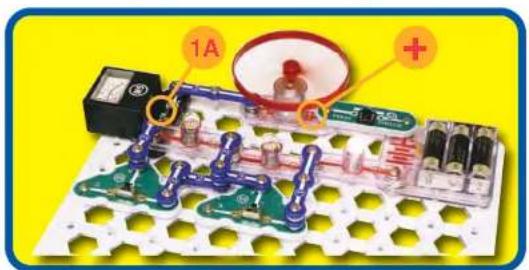
3-SPEED MOTOR (III)
Assembly
Build the circuit and set the meter (M5) on the 1A scale.
Operation
Push the press switch (S2) to turn on the motor (M1) and use the slide switches (S5) to control its speed. The meter measures the current through the motor. Be careful not to touch the motor or fan while it is spinning. You may need to give the fan a push to get it started, but do not touch it while it is spinning.
Description
Here you control the motor speed by diverting some of the current to the lamps (L4).

WARNING: Moving parts. Do not touch the fan or motor during operation.

WARNING: Do not lean over the motor.
Educational Corner:
Turn off the slide switches (S5 position B) and get the fan spinning fast. Now turn on one of the other lamps (S5 position C) and watch how long it takes to light. The lamp takes a few seconds to get bright because it takes time to heat up the filament with a low current.
Electric Paths


3-POSITION SWITCH
Assembly
Build the circuit and set the meter (M5) to the 1A scale.
Operation
Push the press switch (S2) to turn on the right lamp and use the slide switches (S5) to control the other parts. The meter measures the circuit current.
Description
This circuit uses both slide switches to simulate a larger switch controlling many things.
This circuit has 3 lamps and 1 motor. When the press switch is pushed, 2 of these will always be on - you can't set the slide switches to control more or less.

WARNING: Moving parts. Do not touch the fan or motor during operation.

WARNING: Do not lean over the motor.
Educational Corner:
Some switches can be very complex, switching groups of parts on or off at once.

natural_image
Three types of electrical relays and switches on a yellow background (no text or symbols visible)

Project #38

A "blackout" occurs when part of a city is cut off from the power plants supplying it with electricity. The city will appear "black" from the air at night, since there are no electric lights on. This is usually due to accidents or storms, but is also done to confuse attacking bombers during war.


natural_image
Cartoon stick figure with blue body and numbered limbs, set against a yellow oval background (no text or symbols)3-POSITION SWITCH (II)
Assembly
Build the circuit and set the meter (M5) to the 1A scale.
Operation
Push the press switch (S2) to turn on the right lamp (L4) and use the slide switches (S5) to control the other parts. The meter measures the circuit current.
Description
This circuit uses both slide switches to simulate a larger switch controlling many things.
This circuit has 3 lamps and 1 motor (M1). When the press switch (S2) is pushed, either 1 or 3 of these will always be on - you can't set the slide switches to control more or less.

WARNING: Moving parts. Do not touch the fan or motor during operation.

WARNING: Do not lean over the motor.
Educational Corner:
The electricity supplied to your home and school by your local electric company is not a constant voltage like that from a battery. It averages about 120V but is constantly changing, due to the design of the generators that produce it. This is not a problem, since all equipment that uses it accounts for this change.
Electrical current that is changing is called an alternating current, or AC. Because of this, the power from the electric company is also called AC power. An electrical signal that is constant and unchanging is called a direct current, or DC. The power from a battery is also called DC power.
Electric Paths
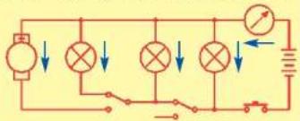

Project #39
4-POSITION SWITCH

A "brownout" occurs when power plants cannot supply enough current to a city during high demand, and must reduce the voltage below 120V. This sometimes occurs on hot days in summer when everyone is using their air conditioners.

natural_image
Illustration of a blue robot figure with numbered parts and a circuit board, alongside a small electronic device (no text or symbols on the diagram itself)Assembly
Build the circuit and set the meter (M5) to the 1A scale.
Operation
Set the slide switches (S5) to all positions and see what lights.
Description
This circuit has four different lamp (L4) combinations, as if the two slide switches were acting like one four-position switch. The right lamp will always be on but its brightness varies. The other lamps may be on or off.
This right lamp is always on but there are four different paths to complete its circuit, because there are four slide switch combinations. The meter measures the current through one of the paths, see if you can find the others.
Educational Corner:
Actual electrical connections are made with solder, not snaps.
Solder is a special metal made mostly of tin that melts at relatively low temperature (about 500^ F). Solder is applied and melted around a joint where a connection is being made; it creates a solid bond between the metals.

After Soldering

Electric Paths
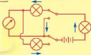

Project #40
AND

Snappy says: Engineers refer to this switching combination as an AND sub-circuit (short for "this AND that"). It even has its own symbol.
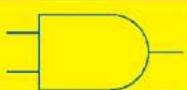
AND Gate

natural_image
Electronic circuit board with components and connectors on a white perforated base (no visible text or symbols)
natural_image
Cartoon character with blue limbs and a smiling face, set against a yellow background (no text or symbols)Assembly
Build the circuit shown.
Operation
Use the switches (S2, S5) to turn on the lamp (L4).
Description
The lamp will only light if there is a complete ("closed") circuit. This means that the left AND right slide switches (S5) have to be on (position C). The press switch (S2) must be on (pushed).
Educational Corner:
Having to turn on a lot of switches just to turn on a lamp seems simple but is very important. The press switch could represent an on/off switch on an electric saw, one of the slide switches could be a safety switch on the saw, and the other slide switch could be a fuse box in your basement. Safety is very important in electrical wiring.
AND circuits are used in home security systems, where contacts across windows and doors are wired together in a series circuit like this one. Opening any door or window breaks the circuit and triggers an alarm.
Electric Paths
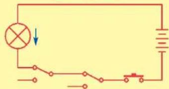
natural_image
Simple electrical circuit diagram with battery, switch, lamp, and resistor (no text labels)
Project #41
AND NOT

Snappy says: this type of switching combination is a NAND sub-circuit (short for "NOT this AND that"). It has its own symbol.
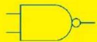
NAND Gate

Assembly
Build the circuit shown.
Operation
Hold down the press switch (S2), then use the slide switches (S5) to turn the fan on or off.
Description
If the press switch is on, then the fan will be off unless both lamps (L4) are on. In other words, the fan will be off if the left lamp AND the right lamp are NOT off.

WARNING: Moving parts. Do not touch the fan or motor during operation.

WARNING: Do not lean over the motor.

natural_image
Electronic circuit board with components and a magnified view of a battery (no text or symbols visible)Educational Corner:
Suppose you wanted to monitor the voltage to a circuit, to see if the batteries were getting weaker. You could use the meter to measure the voltage, then read and record every hour. Then you have a series of numbers showing how the voltage was changing. Even if you watched the meter continuously, you probably wouldn't remember what the voltage was a week later unless you wrote it down.
Representing an electrical signal as a series of numbers is digital electronics. Computers store and process almost all their information as series of recorded numbers.
Sometimes it is easier to process information as a digital series of numbers (computers), and sometimes it is easier to use a continuously changing voltage (AM
radios). Many products use both methods on the same information but at different times. The disadvantage of digital systems is that they are more complex since they have to store and process all the numbers. The advantages are that IC technology makes it inexpensive to store and process information, and digital systems are more protected from interference.
Electric Paths


Project #42


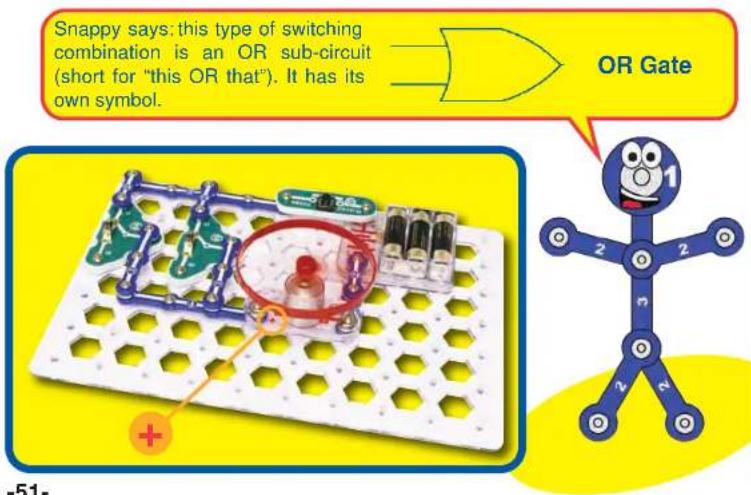
Assembly
Build the circuit shown.
Operation
Hold down the press switch (S2), then use the slide switches (S5) to turn the fan on or off.
Description
If the press switch is on, then the fan will be on if either the left OR right slide switch is set to ON (position C) OR both slide switches are set to ON (position C).
The same type of circuit is used throughout your home, such as having several sensors controlling a security light.

WARNING: Moving parts. Do not touch the fan or motor during operation.

WARNING: Do not lean over the motor.
Educational Corner:
Simple switching circuits like this are the basic building blocks of computers. Large arrays of simple sub-circuits like AND, NAND, OR, and others are used to add and multiply numbers together in the heart of advanced microprocessors. In computers, the switches used here are transistors controlled by other parts of the computer.
Electric Paths
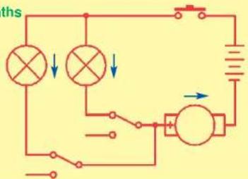

Project #43
COMPASS

Educational Corner:
All materials have tiny particles with electric charges, but these are so well balanced that you do not notice them unless an outside voltage disturbs them. The same tiny particles also have magnetic charges, which are usually so well balanced that you do not notice them unless a magnetic field disturbs them.
Magnets are materials that concentrate their magnetic charges at opposite ends. One side attracts while the other repels, but the overall material is neutral. Most magnets are made of iron. The name "magnet" comes from magnetite, an iron ore that magnetism was first seen in.
The earth we live on is a giant magnet, due to its iron core. A compass needle always points north because it is attracted to the earth's magnetic field. The opposite ends of a magnet are often labeled north and south, representing the north and south poles of the earth. For centuries ships have used suspended magnets for navigation.
Operation
- Hold your compass away from everything, notice that the red arrow always points north. Spin it around, the red arrow will adjust and resume pointing north.
- Now place the compass next to a large iron object, such as a refrigerator or car. If the object is heavy enough, the red arrow will point toward it.
- Now place your magnet near the compass. The red arrow will immediately point toward the black "S" side of the magnet, ignoring a nearby refrigerator.
- Pull out a 2-snap wire, a paper clip, the electrodes, the iron core rod, and the thin bar. Decide which of these you think the magnet will pick up, then try it and see if you were right. Do the same for other materials in your home.
Description
- The earth's core is made of iron, which has a magnetic field. The compass points north because it is attracted to this magnetic field. This allows compasses to be used for navigation.
- Large iron objects also exert a small magnetic field, which may attract a nearby compass. The magnetic field is much weaker than the earth's, but much closer to the compass.
- Magnets have been induced to have a concentrated magnetic field at either end. This magnetic field is much stronger than ordinary iron objects that may be nearby.
- The physical properties of iron make it easy to induce a magnetic attraction in. This doesn't work for other metals or other materials.


Project #44
MAGNETIC FIELDS

Operation
- There is an area around a magnet where it can affect other objects, called a magnetic field. It is strongest at the ends of the magnet.
- Slowly move your compass around the magnet and watch its pointer to see the magnetic field.
- Shake the iron filings pack to spread the filings evenly. Move the magnet over the filings and you can see the magnetic field in them.
- Loop two paper clips together. Hold them near the magnet and move them around it to see the magnetic field.
natural_image
Blue stick figure with numbered limbs and a smiling face, no text or symbols presentEducational Corner:
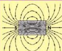
Magnet - magnetic field
A magnet has a magnetic field, and a battery has an electric field. The north and south poles of a magnet are comparable to the positive and negative terminals of a battery.
Electric and magnetic fields affect each other. If you place a magnet next to a radio your reception can be disturbed.
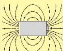
Battery - electric field


Project #45


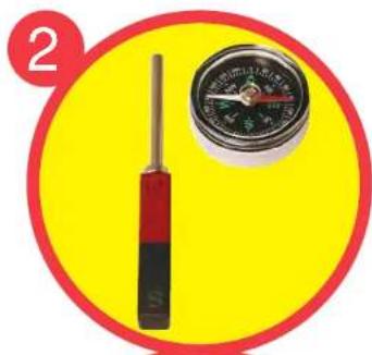
natural_image
Yellow circular background with a screwdriver and a compass, no visible text or symbols
natural_image
Yellow circular background with a red border and a compass showing pressure gauge (no text or symbols)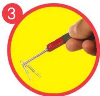
natural_image
Hand holding a red-handled screwdriver against a yellow background (no text or symbols)IRON EXTENSION
Operation
- Place the iron core rod on one side of the magnet, making a chain. Hold/move the compass along this chain to see how the magnet's magnetic field has been extended through the rod. You can also use the iron fillings pack to see the magnetic field.
- Hold the compass close to the iron core rod, then remove it from the magnet. See how the compass reacts to this change to the magnetic field.
- You can use the iron core rod to help the magnet pick up paperclips at a greater distance than normally possible.
Snappy says: Permanent magnets are made by exposing iron (or other metals) to a much stronger magnetic field, usually from an electromagnet.

Educational Corner:
Magnets can magnetize other materials (usually iron), concentrating their magnetic charges at opposite ends. This causes the magnetic attraction/ repulsion that you see. Magnetization can be temporary or long-lasting,
depending on the materials and magnetic force used. For example, Paper Clips attracted to a magnet sometimes stick together after the magnet is removed. Most magnets can be demagnetized using heat or vibration.

Project #46

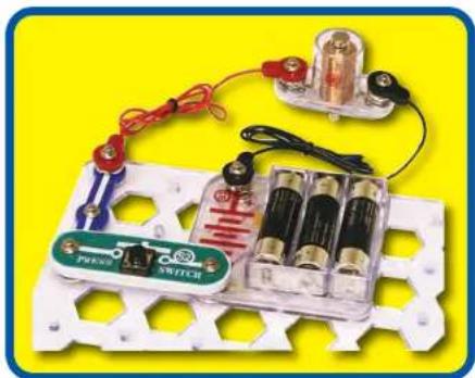
natural_image
Electrical circuit components including battery, switch, and power supply on a white perforated base (no visible text or symbols)
ELECTRONIC MAGNET
Assembly
Build the circuit shown. Place the iron core rod inside the electromagnet (M3) and secure it with the rubber grommet. This project works best if you have new alkaline batteries.
Operation
Hold the electromagnet near something made of iron and push the switch (S2). While pressed, the electromagnet will attract small metal parts like nails or will stick to a hammer or refrigerator. Release the switch and the attraction disappears.
Description
Pressing the switch turns on an electric current which transforms the electromagnet from an ordinary coil of copper wire into a magnet.
Educational Corner:
An electron current flowing in a wire has a tiny magnetic field. By looping a long wire into a coil the tiny magnetic field is concentrated into a large one.
The strength of the magnetic field depends on how much current is flowing in the wire and how many loops of wire.


Project #47
ELECTROMAGNET MAGNETIC FIELD


natural_image
Illustration of a battery and paperclip inside a yellow circle (no text or symbols)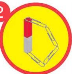
natural_image
Simple 3D geometric shape resembling a cube with red and gray segments, set against a yellow circular background (no text or symbols)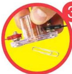
natural_image
Close-up of a hand holding a transparent plastic component with a red tool, next to a white paperclip on a yellow background (no text or symbols visible)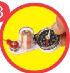
natural_image
Hand holding a compass and a small container on a white tray against a yellow background (no text or symbols visible)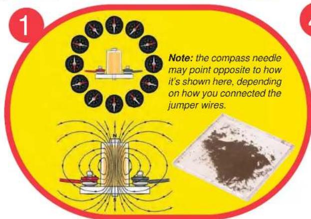

natural_image
Illustration of a wooden tool with wires and a red cap, set against a yellow circular background (no text or symbols)Operation
- Use the circuit from the preceding project, with the iron core rod in the electromagnet (M3). An electronic magnet has a magnetic field just like an ordinary magnet. Hold your compass next to the electromagnet and push the press switch (S2). Move the compass all around the electromagnet and watch where the compass points.
- The magnetic field created by a magnet occurs in a loop. You can see this using paper clips.
- Remove the iron core rod from the electromagnet. Now push the press switch again and try to pick up things with the electromagnet. The attraction is now very weak.
The iron core rod concentrated the magnetic effects of the electromagnet. You can use the compass to see that electronic field is now much weaker.
- Materials made of iron concentrate their magnetic effects at both ends. The center of the material is magnetically neutral because the attraction from each end is the same.
The magnetic field created by the electromagnet works the same way. It is strongest at both ends but neutral in the center. But the electromagnet is hollow - so iron at one end will be sucked into the middle.
Lay the electromagnet on its side. Hold the thin rod next to the center hole and push the press switch to suck it inside. Hold the switch and gently pull the rod to see how much suction the electromagnet has.

natural_image
Cartoon illustration of a blue robotic arm with numbered joints and a smiling face (no text or symbols)Snappy says: you can turn on the switch to pick up things with the electromagnet, then release the switch to drop them. This is done with large magnets at factories or junk yards.

Project #48
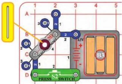
Note: the magnet poles may be opposite of how it's shown here, depending on how you connected the electromagnet (M3).
Coils store energy in a magnetic field, while static electricity stores energy in an electric charge across a material (an electric field).

natural_image
Cartoon illustration of a blue robotic arm with numbered joints and a smiling face (no text or symbols)
natural_image
Close-up of a mechanical component with a copper-colored cylindrical part and blue base, set against a yellow background (no visible text or symbols)
natural_image
Close-up of a mechanical component with spool and coiled parts, no visible text or symbols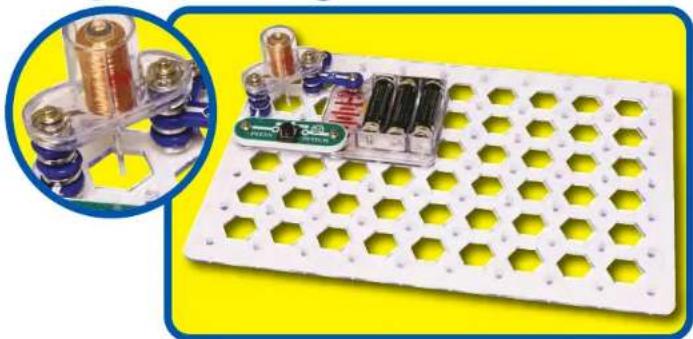
natural_image
White hexagonal grid device with cylindrical batteries and a battery pack, set against a yellow background (no text or symbols visible)ELECTROMAGNET TOWER
Assembly
Build the circuit as shown and drop the thin rod into the electromagnet (M3).
Operation
Push the press switch (S2) several times. The thin rod gets sucked into the electromagnet and can be suspended there, or you can bounce it up and down.
When you push the press switch, the thin rod gets sucked up and wiggles up and down until settling in position just below center. Measure how high you get the thin rod to go, then try with old and brand new batteries. Remove a 1-snap from under each side of the electromagnet, then see how high the thin rod will go.
Part B: With the switch pressed and the thin rod suspended in mid-air, hold the magnet near the thin rod. Notice that the red (N) side of the magnet repels the thin rod but the black (S) side attracts it.
Educational Corner:
Magnets concentrate their magnetic effects at both ends. The magnetic field is strongest at both ends but neutral in the center, because the attraction from each end is the same. But the electromagnet is hollow - so iron at one end will be sucked into the middle.
The magnetic field produced by the electromagnet has direction just like a normal magnet. Opposite ends of magnets attract, while like ends repel each other.
Find two magnets in your home. Try putting them together, then flip one around. They will attract one way but repel the other way.

Project #49
ELECTROMAGNETIC SUSPENDER
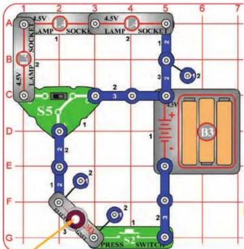
A transformer is a magnetic bridge, since we use magnetism to cross an air gap that electricity cannot cross by itself.
natural_image
Blue stick figure with numbered limbs and a smiling face, standing on a yellow oval (no text or symbols)Assembly
Build the circuit as shown and drop the thin rod into the electromagnet (M3).
Operation
Set the slide switch (S5) to both positions and push the press switch (S2) several times; compare how high the thin rod will go. Next, flip the switch slide back and forth WHILE keeping the press switch pushed; the thin rod stays suspended but its height changes.
The lamps (L4) are used to reduce the current through the electromagnet, they will not light.
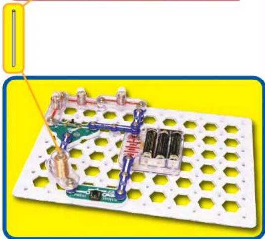
natural_image
Electronic circuit board with components and wiring, no visible text or symbolsEducational Corner:
If a current through a coil can magnetize an iron bar, what if you had another coil from a different circuit wrapped around the same iron bar? The magnetization of the iron bar would create a current in the other circuit. This is a transformer, which allows one circuit to create a current in another circuit using magnetic fields.
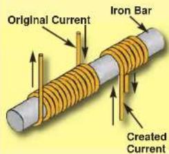
Transformers allow circuits to be isolated from each other, since the connection between them is magnetic and not electrical. Transformers can also change the v using coils with mo loops of wire.
When electric power companies transport electricity across great distances (like between power generating plants and cities), they use very high voltages and low currents since this reduces power loss in the wires. Large transformers convert this to 120V, which is supplied to homes and offices. Many products (like computers) then use small transformers to

convert this to smaller or larger voltages as needed.


Project #50
ELECTROMAGNET DIRECTION
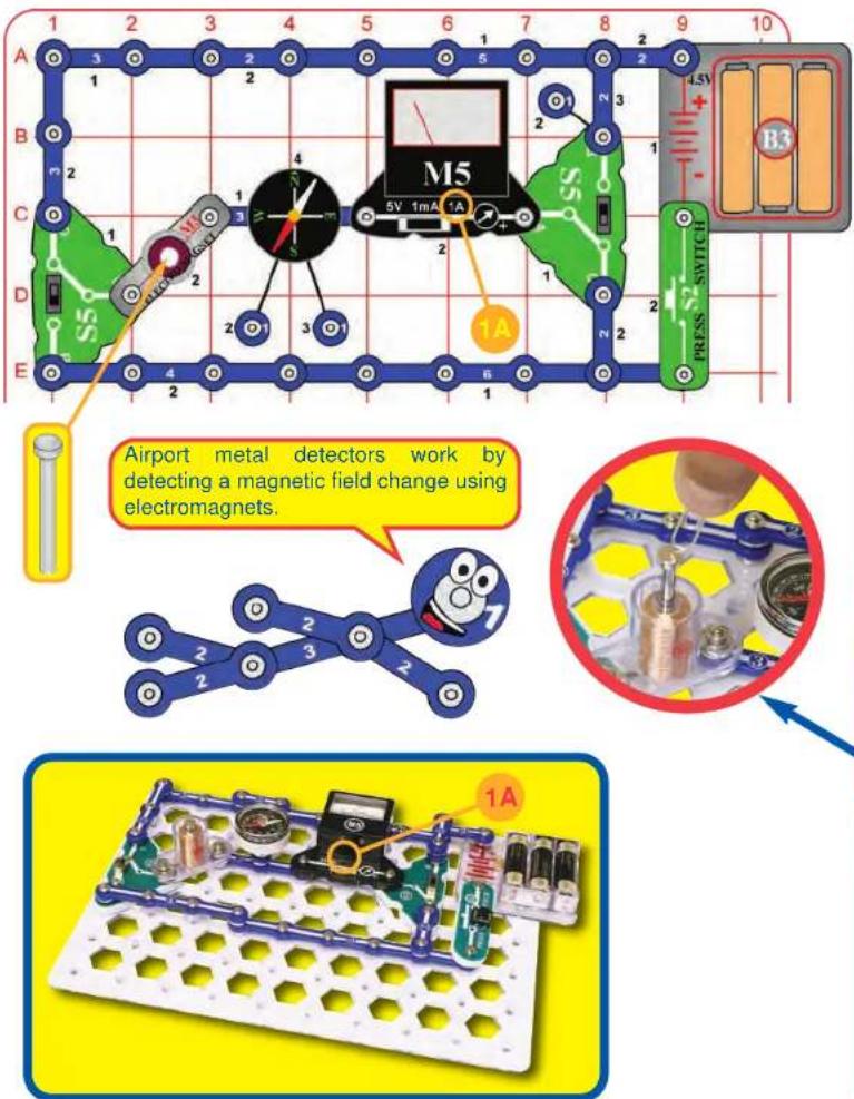
Assembly
Build the circuit shown. Place the iron core rod in the electromagnet (M3), set the meter (M5) to the 1A scale, set the slide switches (S5) to position B.
Operation
Push the press switch (S2). The meter shows a current is flowing and the compass needle is attracted to the electromagnet.
Note: in some cases your M5 meter may not be sensitive enough to measure the current. If your meter shows zero, switch to the 1mA setting, then switch back (the 1mA scale prevents the compass from working here).
Now flip both slide switches (to position C) and push the press switch again. The meter shows no current (because electricity flows in the other direction) and the other side of the compass needed is attracted to the electromagnet (magnetic field is reversed). In some cases you may need to hold the compass closer to the electromagnet for the needle to change sides.
If you remove the iron core rod from the electromagnet, the compass needle attraction will be much weaker.
Description
The direction of a magnetic field from a current flowing in a wire (or coil of wire) depends on the direction of the electric current.
For more fun: with the press switch pushed, try lifting the iron core rod out of the electromagnet with a paper clip.
Educational Corner:
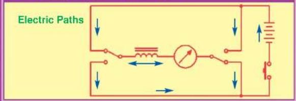

Project #51
WIRE MAGNET

In 1820 Hans Christian Oersted of Denmark noticed that an electric current affects a compass needle. This was the discovery of electromagnetism!
Assembly
Build the circuit as shown. This circuit works best with new alkaline batteries.
Notes:
- Place the red jumper wire near the 6-snap wire at the bottom of the circuit. Keep it as far away from the compass as you can.
- The 5-snap wire is connected on level 4 on the left side and at level 3 on the right side, over the compass. Make sure it is securely snapped.


natural_image
Illustration of a robotic circuit board with components and wiring, no visible text or symbolsOperation
Set the slide switches (S5) so that the lamps (L4) are on. While watching the compass, flip both slide switches (reversing the current through the lamps). You should see the compass needle move a little - indicating a change in the magnetic field from the wire.
Description
Any electric current flowing in a wire has a magnetic field, but it is usually very small. An electromagnet creates a noticeable magnetic field by looping the wire very many times to concentrate the magnetic field from it.
Note: The magnetic field produced by the wire is very small. If the compass needle does not move, check your batteries (B3), make sure you are not close to any iron objects, and make sure the red jumper is far from the compass.

Project #52

Snappy says: many vending machines sort coins using magnetism, since fake coins will have different magnetic properties.

natural_image
Cartoon illustration of a blue robotic arm with numbered joints and a smiling face (no text or symbols)
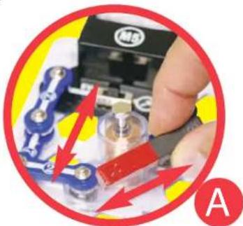
natural_image
Close-up of a hand inserting a component into a small electronic device, with red arrows indicating direction (no text or symbols visible)
natural_image
Close-up of hands using a computer to adjust a component, with red arrows indicating motion (no visible text or symbols)Educational Corner:
In separate experiments in the 1830s, Michael Faraday and Joseph Henry discovered that electric currents could be induced by changing magnetic fields.
This simple concept became extremely important to our society. Today, high pressure water or steam (heated by burning oil or coal) spins large magnets in coils to produce the electricity that runs our cities.
MAGNETIC INDUCTION
Assembly
Build the circuit as shown. Place the iron core rod into the electromagnet (M3) and set the meter (M5) to the 1mA scale.
Operation
A. Move the magnet left-right or up-down near the electromagnet. You may see the meter pointer wiggle, which indicates a small current.
B. Place the magnet on the iron core rod and use it to move the rod up and down IN the electromagnet. The meter pointer should move or wiggle slightly, showing a current is produced.
If you have a more powerful magnet in your home, use it in place of the Snaptricity® magnet. A more powerful magnet will create a larger current and be easier to measure.
Description
The meter shows an electric current even though no batteries are used. By moving the magnet near the coil, you have induced (created) a current in the circuit. You have made electricity from magnetism - an electric generator!
Battery-less flashlights and watches use this idea. By shaking the flashlight or watch, you move a magnet in it, which makes a current in a coil of wire, which powers the unit.

Project #53
MOTOR
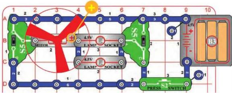

WARNING: Moving parts. Do not touch the fan or motor during operation.

WARNING: Do not lean over the motor.
Snappy says: the switches reverse the direction of electric current through the motor, changing the direction it spins. But the lamps don't care which way electricity is flowing.

natural_image
Cartoon illustration of a blue mechanical linkage with numbered joints and a smiling face (no text or symbols)
natural_image
Exploded view of a mechanical circuit board with components and a highlighted positive charge symbol (no text or labels)Assembly
Build the circuit as shown.
Operation
Set the slide switches (S5) so that both are set to the same position (B or C), and push the press switch (S2). The lamps (L4) light and the fan spins.
Flip the slide switches to the other position and push the press switch again. The lamps still light and the fan spins the other direction.
Description
Motors are used throughout our society to convert electricity into mechanical motion.
Educational Corner:
How does electricity turn the shaft in the motor? The answer is magnetism. The motor is the opposite of an electromagnet. Moving a magnet near a coil of wire can make a current flow in it (like the electromagnet), but a current flowing can move a magnet.
Inside the motor is a coil of wire mounted on a shaft. The motor shell has a magnet on it. When electrically flows through the coil of wire, it repels from the magnet on the motor shell and the shaft spins. If the fan is on the motor shaft then its blades will create airflow.

natural_image
Illustration of a vintage oil lamp with five analog compass faces (no text or symbols)To prove the motor has a magnet inside, move your compass around it. The red needle will be attracted to one side but repelled from the other.

Electric Paths

natural_image
Pure electrical circuit diagram with resistors, lamps, and a battery (no text or symbols)
Project #54


WARNING: Moving parts. Do not touch the fan or motor during operation.

WARNING: Do not lean over the motor.
Snappy says: switching circuits like this are commonly used to control motors in products like remote-controlled cars. Electronic controlled transistors are used in place of the switches, and the motor drives the wheels in the car.

natural_image
Illustration of a blue robotic arm with numbered joints and a smiling face (no text or symbols)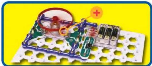
natural_image
Electronic circuit components including a battery, switch, and motor on a grid board (no visible text or symbols)PROPELLER AND FAN
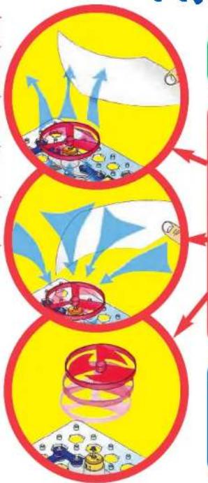
flowchart
graph TD
    A["Step 1: Food Delivery & Storage"] --> B["Step 2: Storage & Delivery"]
    B --> C["Step 3: Storage & Storage & Storage"]
Assembly
Build the circuit shown.
Operation
Set the slide switches (S5) to position B and push the press switch (S2). The fan blades suck in air around the motor (M1) and push it straight up. Hold a sheet of paper above the motor, it will get pushed up and away from the fan.
Flip the slide switches to position C and push the press switch again. The fan spins the other direction and sucks in air from above and pushes it down to the table. If the fan is spinning fast enough, then it will rise into the air when you release the press switch. If you hold a sheet of paper near the motor, it will get sucked into the fan.
Description
When the motor is blowing air up, it is a fan - just like the ones in your home. It will cool you off on a hot day.
When the motor is sucking air in, it is a propeller - just like the ones on helicopters or small airplanes.
Educational Corner:
How does the fan rise? Think first about how you swim. When your arms or legs push water behind you, your body moves ahead. A similar effect occurs in a helicopter - the spinning blades push air down, and create an upward force on the blades. If the blades are spinning fast enough, the upward force will be strong enough to lift the helicopter off the ground. While the switch is pressed, the motor rotation locks the fan on the motor shaft. The fan does not spin fast enough to lift the entire circuit off the ground. When the motor is turned off, the fan unlocks from the shaft. The fan rises into the air like a helicopter, since it is no longer held down by the weight of the full circuit.
Electric Paths

natural_image
Pure electrical circuit lines without any symbols
Project #55
BACK EMF


WARNING: Moving parts. Do not touch the fan or motor during operation.

WARNING: Do not lean over the motor.

natural_image
Electronic circuit board with hexagonal grid pattern and a battery, set against a yellow background (no text or symbols visible)Assembly
Build the circuit as shown, leave the fan off the motor (M1).
Operation
Place your finger on the top of the motor shaft to prevent it from spinning, then push the press switch (S2) - the lamps (L4) are bright. Now release the motor shaft and press the switch again - the lamps get dim or go out as the motor speeds up. DO NOT TOUCH THE MOTOR WHILE IT SPINS. Next, place the fan on the motor and push the press switch again - the lamps stay bright as the fan speeds up.
Description
The voltage from the batteries (B3) pushes an electric current through a coil in the motor, which spins the shaft using magnetism. But the spinning shaft also uses magnetism to produce a current in the coil, which opposes the current from the batteries.
The result is that the motor has low resistance when the shaft isn't spinning fast, allowing a higher current to make the lamps bright. When the shaft is spinning really fast without the fan, the motor has high resistance, limiting the current and keeping the lamps dim.
Educational Corner:
The voltage/current produced by a motor when it is spinning is called its Back Electro-Motive-Force (Back EMF); this may be thought of as the motor's electrical resistance. The motor's Front Electro-Motive-Force is the force it exerts in trying to spin the shaft. This circuit demonstrates how the Back EMF increases and the overall current decreases as the motor speeds up.
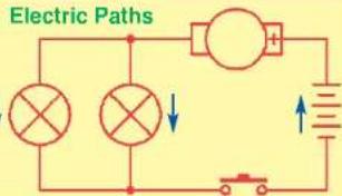

Project #56
GENERATOR


WARNING: Moving parts.
Do not touch the fan or motor during operation.

WARNING:
Do not lean over the motor.

natural_image
Simple red Y-shaped diagram inside a circle (no text or symbols)Snappy says: the most important aspect of electricity in our society - more important than the benefits of the Internet - is that it allows energy to be easily transported over distances.

natural_image
Cartoon illustration of a blue robotic arm with numbered joints (no text or symbols)
Assembly
BE SURE THE SLIDE SWITCH IS SET TO POSITION C BEFORE COMPLETING THE CIRCUIT. Build the circuit as shown, leave the fan off the motor (M1). Set the meter (M5) to the 5V scale for now.
Operation
Set the switch to position B to get the motor spinning, then set it back to C and watch the meter to see how much voltage is produced.
Next, set the meter to the 1A scale and set the switch to B for a few seconds, then back to C and watch the current produced.
Now put the fan on the motor and repeat the above tests to see what voltage and current are produced with the fan on the motor.
Description
This circuit uses the batteries (B3) to get the motor spinning, then disconnects the batteries and uses the motor as a generator. A generator uses mechanical motion (here the spinning motor shaft) to create electricity (a current in a coil in the motor). The meter shows how much current and voltage are produced by the spinning shaft, with and without the fan.
Educational Corner:
Nearly all of the electricity used in our world is produced at enormous generators driven by steam or water pressure. Wires are used to efficiently transport this energy to homes and businesses where it is used. Motors convert the electricity back into mechanical form to drive machinery and appliances.

natural_image
Illustration of an industrial facility with red and white chimneys emitting smoke, connected by a bridge and power lines (no text or symbols visible)Not only can electricity be transported over long distances, it can also be transported over tiny distances. Try to imagine a plumbing structure of the same complexity as the circuitry inside a portable radio - it would have to be large because we can't make water pipes so small. Electricity allows complex designs to be made very small.
Electric Paths


Project #57
MAKE YOUR OWN GENERATOR

Snappy says: gears are used between two wheels or shafts. One wheel spins at low speed but with great force, while the other wheel spins at high speed but with much less force. This can increase efficiency or give greater control.

natural_image
Illustration of a blue robot figure with numbered joints and a speech bubble containing green gears (no text or symbols)Assembly
Build the circuit and set the meter (M5) to the 1mA scale.
Operation
Spin the motor (M1) top clockwise with your fingers and watch how much current is produced. (Clockwise means in the direction in which the hands of a clock rotate.)
Now spin the motor in the other direction (counter-clockwise). You won't see much current produced now because it is produced in the other direction - the meter needs to be flipped around. Instead of flipping the meter around, flip the motor around to see this.
Description
This circuit is a true generator, using motion (and magnetism) to make an electric current.
Notice that this circuit used the 1mA meter setting while the preceding circuit used the 1A setting (1000 times greater). You can produce a much higher current by spinning the shaft much faster.
Hand-cranked generators like this are used in some flashlights instead of batteries. They use gears to spin the shaft much faster.

Educational Corner:
In electric power plants, the same thing happens but on a much larger scale. High-pressure steam or water spins a shaft, which uses magnetism to make an electric current in a coil of wire.
Changing the direction you spin the shaft changes the direction of the magnetic field produced, which changes the direction of the electric current produced. This is known as Lenz's Law, after Russian physicist H. F. E. Lenz who studied electromagnetic induction in the 1800's.


Project #58

If you can spin the shaft really fast then you may be able to light the lamp:


natural_image
Close-up of mechanical components with blue and red fittings, no visible text or symbolsSTRING GENERATOR
FOR ADVANCED USERS - ADULT SUPERVISION RECOMMENDED
Assembly
Build the circuit and set the meter (M5) to either the 1mA or 1A scale.
Operation
Using the string, make a small loop at one end and put it on a prong of the motor (M1) top. Wind a few feet of the string around the motor shaft (wind it so that pulling the string will spin the motor shaft clockwise). Then pull the string gently but fast, watching the current produced in the meter. Get an adult to help with this if needed.
If you wind the string well and pull it fast, you can move the meter on the 1A scale. If not, you can use the 1mA scale to easily see the effect.
A spare motor top is included with this kit in case you break any of the prongs on the motor top. Use a screwdriver to pry off the broken piece, then push the new one on.


natural_image
Close-up of a hand operating a voltmeter with a switch, set on a patterned surface (no visible text or symbols)Description
This circuit shows how much more current is produced when you spin the motor shaft faster.
In many power plants, coal or oil is burned to heat water creating steam, which spins a turbine to make electricity.

natural_image
Illustration of a blue robotic arm with numbered joints and a cartoon face (no text or symbols)
Project #59


natural_image
Electronic circuit board with components and wiring, no visible text or symbols
natural_image
Illustration of a blue stick figure with numbered limbs and a smiling face, set against a yellow oval background (no text or symbols)MOTION ENHANCER
Assembly
Build the circuit. Leave the fan off the motor (M1). Set the slide switch (S5) to position C. Leave the red jumper wire off for now.
Operation
Give the motor shaft a spin with your finger. Notice how easily it spins, in both directions.
Now connect one end of the red jumper wire to the 3-snap wire, and hold the other end to the center spring in the battery holder (B3). Spin the motor shaft with your finger again, while still touching the red jumper snap to the spring in the battery holder. In one direction (clockwise) it will spin more easily than before, but less easily than before in the other direction (counter-clockwise).
Description
There is a small current through the motor, this helps to spin in one direction but resists spinning in the other direction.
The slide switch adjusts the motor current, position B will not enhance/resist the spinning as much as position C.
Educational Corner:
Electric Paths


Project #60
HOLDING DOWN
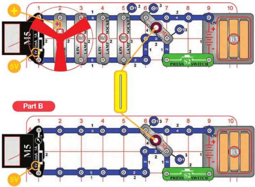


natural_image
Illustration of a blue stick figure with numbered limbs and a yellow base (no text or symbols)Assembly
Build the circuit. Set the meter (M5) to the 5V scale, place the fan on the motor (M1), and drop the thin rod into the electromagnet (M3).
Operation
Push the press switch (S2). The fan spins, the lamps (L4) light, and the meter measures the voltage. Nothing happens to the thin rod. Notice that the voltage is much lower than the normal 4.5V; the motor and lamps are overloading the batteries (B3), so the voltage drops.
Part B: Remove the motor and lamps from the circuit, then push the press switch again. Now the measured voltage is much higher, and the thin rod gets sucked up by the electromagnet.
Description
The motor and lamps overloaded the batteries and prevented the electromagnet from sucking up the thin rod.
Educational Corner:


Project #61
MAKE YOUR OWN ELECTROMAGNET
FOR ADVANCED USERS - ADULT SUPERVISION RECOMMENDED
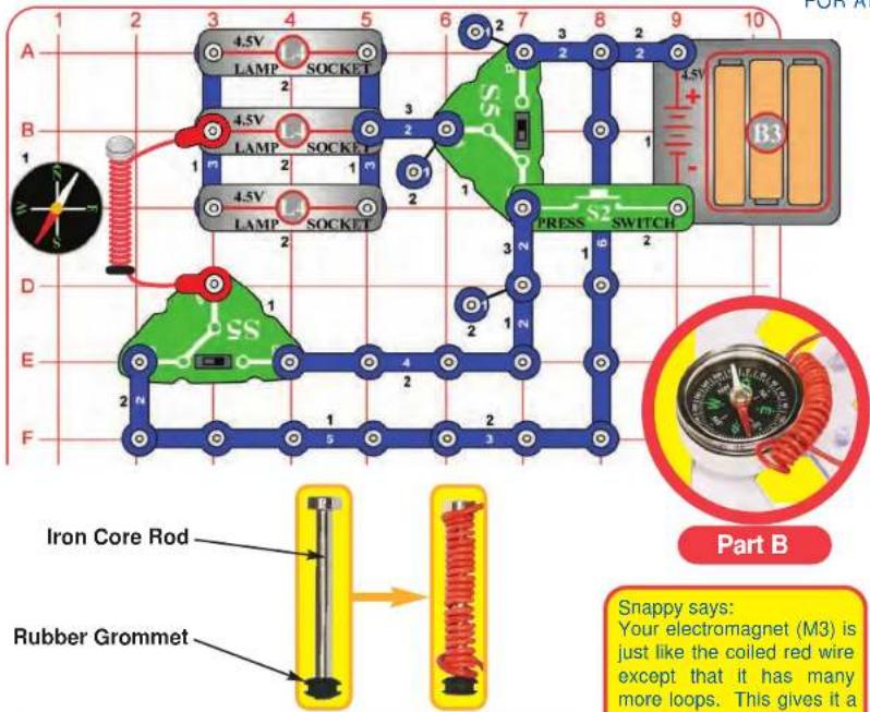

natural_image
Electronic circuit board with components and wiring, set against a yellow background (no visible text or symbols)
natural_image
Cartoon stick figure with blue body and yellow base, no text or symbols presentAssembly
Build the circuit. Place the rubber grommet on one end of the iron core rod and wrap the red jumper wire tightly around it, as shown. Connect the red jumper wire to the circuit. Set the slide switches (S5) so both are in the same position (B or C).
Operation
Push the press switch (S2) and move the iron core rod (with the red wire around it) around the compass and watch how it attracts the compass needle. The lamps (L4) also light when the switch is pressed. Flip both slide switches to reverse the current. Push the press switch again and watch the compass to see how the magnetic field has changed.
Part B: Now take off the rubber grommet and remove the iron core rod, but keep the red wire wound in a coil and connected to the circuit. Push the press switch and watch the compass while moving the coiled red wire around it. Now the compass needle has much less attraction to the red wire.
Description
This circuit shows how wrapping a wire into a coil concentrates the magnetic field from the wire. The more loops of wire a coil has, the stronger the magnetic field produced. So if you only loop the jumper wire around the iron core rod a few times, the magnetic field will not be nearly as strong. You can also see how looping the wire around an iron core increases the magnetic field produced.
Educational Corner:
The iron core rod may remain magnetized for a while after you turn off the circuit. Magnets are usually made by subjecting iron bars to powerful magnetic fields. Some iron ores hold a magnetization for a long time, while other ores lose it as soon as the magnetizing field is removed. Heat and vibration can speed up demagnetization.
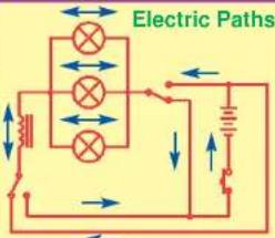

Project #62


natural_image
Close-up of industrial piping equipment with blue and gray components, no visible text or symbolsRelays are electronically controlled switches, which allow a low-voltage circuit to control a high-voltage or high-current circuit. You may never have heard of them, but they are used in many appliances in your home.

natural_image
Close-up of industrial machinery components with a red prohibition symbol (no text or symbols on main subject)
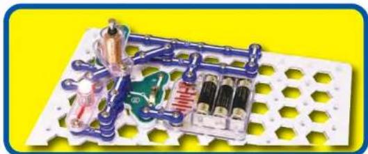
natural_image
Electronic circuit board with components and wiring, no visible text or symbolsRELAY
FOR ADVANCED USERS - ADULT SUPERVISION RECOMMENDED
Assembly
Build the circuit shown. Three 3-snaps are stacked together at base grid location D3-F3. Snap the 4-snap onto the 1-snap at B4, then place it so it lays on the snap at D2 (DO NOT SNAP IT ON). Place the nut-snap on the 4-snap so it will be under the electromagnet (M3). This circuit works best with new alkaline batteries.
Place the rubber grommet on the iron core rod and push the rod into the electromagnet until it is just barely above the nut-snap without touching it (0.025 inches).
Operation
Turn on the slide switch (S5, position C). The lamp (L4) should be on (if off, make sure the 4-snap is touching the 2-snap at D2 without being snapped there). Push the press switch (S2) to turn on the electromagnet. This should raise the 4-snap slightly and turn off the lamp (adjust the position of the grommet on the rod if it does not). If you still can't get it to work, rotate the 1-snap at location B4 to the proper spring direction as shown, this may make the 4-snap move more easily.
Description
This circuit is a relay, which uses one circuit to create a magnetic field that controls another circuit. The current through the electromagnet makes a magnetic field that attracts the nut-snap, which breaks the circuit to the lamp.
Educational Corner:
When you need a relay for a circuit, you usually buy one instead of building one.

Electrical Symbol for Relay Actual Relay

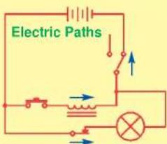

RELAY (II)
FOR ADVANCED USERS - ADULT SUPERVISION RECOMMENDED
Assembly
Build the circuit shown. Three 3-snaps are stacked together at base grid location E4-E6. Snap the 4-snap onto the 1-snap at D2, then place it so it lays on the snap at F4 (DO NOT SNAP IT ON). Place the nut-snap on the 4-snap so it will be under the electromagnet (M3). This circuit works best with new alkaline batteries.
Place the rubber grommet on the iron core rod and push the rod into the electromagnet until it is just barely above the nut-snap without touching it (0.025 inches).
Operation
Part A: Set the left slide switch ("X") to position C and the right slide switch ("Y") to position C. The lamp (L4) should be on (if off, make sure the 4-snap is touching the lamp snap at F4 without being snapped there).
Set the left slide switch (X) to position B to turn on the electromagnet. This should raise the 4-snap slightly and turn off the lamp (adjust the position of the grommet on the rod if it does not). If you still can't get it to work, rotate the 1-snap at location D2 to the proper spring direction as shown, this may make the 4-snap move more easily.
Part B: Keep the left switch (X) on B and flip the right switch (Y) back and forth a few times, waiting a few seconds in each position. When the right switch (Y) is set to C, the lamp should come on for a few seconds, then turn off automatically. This circuit requires precise adjustment; if it doesn't work then make sure the grommet and 4-snap are positioned as described above and start over.
Description
This circuit is a variation of the preceding relay circuit. The current through the electromagnet makes a magnetic field that attracts the nut-snap, which breaks the circuit to the lamp.
Switch Y turns on the circuit and switch X controls the electromagnet. In part B, the lamp flashes briefly because it turns on faster than the electromagnet.

Project #64
FOR ADVANCED USERS - ADULT SUPERVISION RECOMMENDED
RELAY (III)


natural_image
Close-up of mechanical components with blue and green parts, no visible text or symbols
natural_image
Close-up of industrial piping and valves with blue components and a metallic valve, enclosed in a red circular frame (no visible text or symbols)In a relay, the controlling signal and the signal being switched do not affect each other. This is done by using magnetism to open or close a mechanical switch.
Assembly
Build the circuit shown. At base grid location C1-C3, 3-snaps are on levels 1 and 3 and a 2-snap is on level 4. Snap the 4-snap onto the 1-snap at B5, then place it so it lays on the snap at D3 (DO NOT SNAP IT ON). Place the nut-snap on the 4-snap so it will be under the electromagnet (M3). This circuit works best with new alkaline batteries.
Place the rubber grommet on the iron core rod and push the rod into the electromagnet until it is just barely above the nut-snap without touching it (0.025 inches).
Operation
Set the left slide switch ("X") to position C and the right slide switch ("Y") to position C. Lamps B and C should be on (if off, make sure the 4-snap is touching the lamp snap at D3 without being snapped there).
Set the left slide switch (X) to position B to turn on the electromagnet. This should raise the 4-snap slightly, turn off lamp B, and turn on lamp A (adjust the position of the grommet on the rod if it does not). If you still can't get it to work, rotate the 1-snap at location B5 to the proper spring direction as shown, this may make the 4-snap move more easily.
Description
This circuit is a variation of the preceding relay circuits. The current through the electromagnet makes a magnetic field that attracts the nut-snap, which breaks the circuit to the lamp. Switch Y turns on the circuit and switch X controls the electromagnet.

natural_image
Electronic circuit board with components and wiring, no visible text or symbols
natural_image
Blue cartoon stick figure with numbered limbs and a yellow base (no text or symbols)Educational Corner:
Most home appliances operate at 120V. However, the electronic circuits used to control them (either automatically or by interfacing with people) operate at lower voltages (usually 5-15V). Relays allow these low voltage circuits to control high voltage machinery and appliances.


Project #65

BUZZER
FOR ADVANCED USERS - ADULT SUPERVISION RECOMMENDED
Assembly
Build the circuit shown. At base grid location B6-B8, 3-snaps are on levels 1, 3 and 4. Snap the 4-snap onto the 1-snap at A4, then place it so it lays on the snap at C6 (DO NOT SNAP IT ON). Place the nut-snap on the 4-snap so it will be under the electromagnet (M3). This circuit works best with new alkaline batteries.
Place the rubber grommet on the iron core rod and push the rod into the electromagnet until it is just barely above the nut-snap without touching it (0.025 inches).
Operation
Set the slide switch (S5) to position B to turn on the circuit. The lamp (L4) should be on; adjust the position of the grommet until you hear a buzzing sound. If the lamp is off, make sure the 4-snap is touching the lamp snap at C6 without being snapped there. Make sure the 4-snap lays centered on the snap at C6 (vibration tends to move it off-center).
This circuit requires precise adjustment; if it doesn't work then make sure the grommet and 4-snap are positioned as described above and start over. If you still can't get it to work, rotate the 1-snap at location A4 by 90 degrees, this may make the 4-snap move more easily.
Description
As in the preceding relay circuits, the current through the electromagnet makes a magnetic field that attracts the nut-snap, which breaks the circuit to the lamp. However in this circuit attracting the nut-snap also breaks the circuit to the electromagnet, which then releases the nut-snap. This creates a feedback loop which raises and releases the nut-snap in a repeating cycle. The buzzing sound you hear is from raising and releasing the nut-snap many times a second.

Educational Corner:
Sound is a variation in air pressure created by a mechanical vibration. For a demonstration of this, lay one of your stereo speakers on the floor, place your hand on it, and turn up the volume. You should feel the speaker vibrate. Now place a piece of paper on the speaker; if the volume is loud enough, you will see the paper vibrate.
natural_image
Illustration of a hand pressing down on a wooden block (no text or symbols)Electric Paths

BUZZER (II)
FOR ADVANCED USERS - ADULT SUPERVISION RECOMMENDED
Assembly
Build the circuit shown. Two 3-snaps are stacked together at base grid location B2-B4, two snaps are stacked together at grid location B4-C4, and three 2-snaps are stacked together at grid location C5-D5. Snap the 4-snap onto the 1-snap at A6, then place it so it lays on the snap at C4 (DO NOT SNAP IT ON). Place the nut-snap on the 4-snap so it will be under the electromagnet (M3). This circuit works best with new alkaline batteries.
Place the rubber grommet on the iron core rod and push the rod into the electromagnet until it is just barely above the nut-snap without touching it (0.025 inches).
Operation
Set the slide switch (S5) to position B to turn on the circuit. Adjust the position of the grommet until you hear a buzzing sound. Make sure the 4-snap lays centered on the snap at C4 (vibration tends to move it off-center); it should lay there without being snapped. The meter measures the current.
This circuit requires precise adjustment; if it doesn't work, then make sure the grommet and 4-snap are positioned as described above and start over. If you still can't get it to work, rotate the 1-snap at location A6 to the proper spring direction as shown, this may make the 4-snap move more easily.
Description
This circuit is a feedback loop which raises and releases the nut-snap in a repeating cycle. The buzzing sound you hear is from raising and releasing the nut-snap many times a second.
When you hear buzzing, the current is very small but the meter (M5) needle will be vibrating, because the circuit is turning on and off rapidly. If there is no sound, then the current should be about 0.1A, due to the resistance of the electromagnet.

natural_image
Electronic circuit board with components and wiring, set on a hexagonal grid background (no visible text or symbols)
Project #67
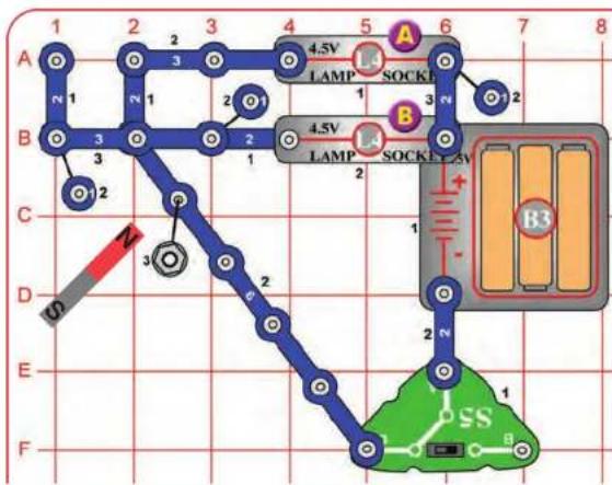
flowchart
graph TD
    A["Node A"] -->|1| B["Node B"]
    B -->|2| C["Node C"]
    C -->|3| D["Node D"]
    D -->|4.5V| E["Switch Block 1"]
    E -->|5| F["Switch Block 2"]
    F -->|6| G["Switch Block 3"]
    G -->|7| H["Switch Block 4"]
    H -->|8| I["Switch Block 5"]
    I -->|9| J["Switch Block 6"]
    J -->|10| K["Switch Block 7"]
    K -->|11| L["Switch Block 8"]
    L -->|12| M["Switch Block 9"]
    M -->|13| N["Switch Block 10"]
    N -->|14| O["Switch Block 11"]
    O -->|15| P["Switch Block 12"]
    P -->|16| Q["Switch Block 13"]
    Q -->|17| R["Switch Block 14"]
    R -->|18| S["Switch Block 15"]
    S -->|19| T["Switch Block 16"]
    T -->|20| U["Switch Block 17"]
    U -->|21| V["Switch Block 18"]
    V -->|22| W["Switch Block 19"]
    W -->|23| X["Switch Block 20"]
    X -->|24| Y["Switch Block 21"]
    Y -->|25| Z["Switch Block 22"]
    Z -->|26| AA["Switch Block 23"]
    AA -->|27| AB["Switch Block 24"]
    AB -->|28| AC["Switch Block 25"]
    AC -->|29| AD["Switch Block 26"]
    AD -->|30| AE["Switch Block 27"]
    AE -->|31| AF["Switch Block 28"]
    AF -->|32| AG["Switch Block 29"]
    AG -->|33| AH["Switch Block 30"]
    AH -->|34| AI["Switch Block 31"]
    AI -->|35| AJ["Switch Block 32"]
    AJ -->|36| AK["Switch Block 33"]
    AK -->|37| AL["Switch Block 34"]
    AL -->|38| AM["Switch Block 35"]
    AM -->|39| AN["Switch Block 36"]
    AN -->|40| AO["Switch Block 37"]
    AO -->|41| AP["Switch Block 38"]
    AP -->|42| AQ["Switch Block 39"]
    AQ -->|43| AR["Switch Block 40"]
    AR -->|44| AS["Switch Block 41"]
    AS -->|45| AT["Switch Block 42"]
    AT -->|46| AU["Switch Block 43"]
    AU -->|47| AV["Switch Block 44"]
    AV -->|48| AW["Switch Block 45"]
    AW -->|49| AX["Switch Block 46"]
    AX -->|50| AY["Switch Block 47"]
    AY -->|51| AZ["Switch Block 48"]
W. B. Elwood invented the reed switch at Bell Telephone Laboratories in 1936.

natural_image
Illustration of a blue robotic arm with numbered joints and a cartoon character (no text or symbols)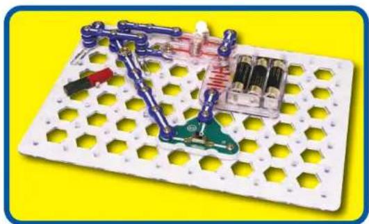
natural_image
Electronic circuit board with components and wiring, set on a white hexagonal grid background (no text or symbols visible)
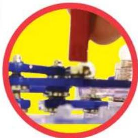
natural_image
Close-up of a hand holding a blue mechanical component against a yellow background (no text or symbols visible)REED SWITCH
Assembly
Build the circuit as shown. Place paper clips at base grid locations B1 and B3, beneath all the parts (this is used to raise the parts slightly). Snap the 6-snap at F5, then place it so it lays on the snap at B2 (DO NOT SNAP IT ON) Place the nut-snap on the 6-snap.
Operation
Set the slide switch (S5) to position C to turn on the circuit, lamp A (L4) should be on.
Now hold the magnet about 0.1 inch above the nut-snap to attract it, this should turn off lamp A and turn on lamp B.
Moving the magnet up and down slightly above the nut-snap should attract and release it, flipping the lamps on and off.
Description
This circuit acts as a reed switch, which is an electrical switch operated by a magnetic field. In this case, the magnet uses the reed switch to control the lamps.
Reed switches are used as proximity switches and in door and window sensors for burglar alarms. Speed sensors on bicycles use a reed switch to detect when a magnet on the wheel passes the sensor.
Educational Corner:
An actual normal open reed switch has two metal tabs inside a glass tube. A magnetic field brings the tabs together to complete a circuit. Here is a typical reed switch:


Project #68
REED SWITCH (II)
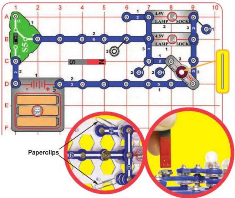

Assembly
Build the circuit as shown. Place paper clips at base grid locations A7 and C7, beneath all the parts (this is used to raise the parts slightly). Snap the 6-snap at B2, then place it so it lays on the snap at B7 (DO NOT SNAP IT ON) Place the nut-snap on the 6-snap. Drop the thin rod inside the electromagnet (M3).
Operation
Set the slide switch (S5) to position B to turn on the circuit, the top lamp (L4) should be off and the bottom lamp should be on. Now hold the magnet about 0.1 inch above the nut-snap to attract it, this should turn on the top lamp, turn off the bottom lamp, and suck the thin rod into the electromagnet. Moving the magnet up and down slightly above the nut-snap should attract and release it, flipping the lamps on and off and bouncing the thin rod.
Description
This circuit acts as a reed switch, which is an electrical switch operated by a magnetic field. In this case, the magnet uses the reed switch to control electrical and mechanical devices (the lamps and thin rod).
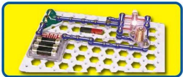
natural_image
Electronic circuit board with components and wiring, no visible text or symbols
Project #69
COLA POWER

Assembly
Set the meter (M5) to the 1mA scale and connect the jumper wires to it. Hold the metal snap of the jumper wires to the electrodes (red to copper), and place them in a cup of cola soda.
Operation
Read the current on the meter. You may switch the meter to the 5V scale to also measure the voltage produced, but the voltage may be too small to measure accurately with a simple meter like M5.
Try replacing the cola with other flavors and compare them.
Throw away the soda used in this project. Wash off the electrodes.
Description
Cola-flavored soda is lightly acidic. The acid is similar to the material used in some types of batteries, though not nearly as strong.
The acid in the cola will react with the copper and zinc electrodes to make an electric current, just like the AA batteries that run your Snaptricity® kit or the larger battery in your family car. As some of the acid in the soda is neutralized, the current produced drops.

FRUIT POWER
Assembly
Squish or roll a lemon a few times to break up some of the cells inside (tomatoes or grapefruit also work). Stick the copper and zinc electrodes into the lemon. Set the meter (M5) to the 1mA scale and connect the jumper wires to it. Hold the metal snap of the jumper wires to the electrodes (red to copper).
Operation
Read the current from your "lemon battery" on the meter. Try placing the electrodes in different parts of the lemon to see how the current changes. You may switch the meter to the 5V scale to also measure the voltage produced, but the voltage may be too small to measure accurately with a simple meter like M5. You may see the current/voltage slowly drop as the "lemon battery" is used up.
If you don't measure any current, move the electrodes closer together or to a different place on the fruit.
Replace the lemon with other fruits or vegetables such as a tomato, grapefruit, orange, carrot, or onion; see how much current they produce.
Throw away the fruits and vegetables when you are finished with this project. Wash off the electrodes.
Description
Some fruits and vegetables have a sour taste because they are lightly acidic. The acid in them is similar to the material used in some types of batteries, though not nearly as strong.
The acid in the fruit will react with the copper and zinc electrodes to make an electric current, just like the "AA" batteries that run your Snaptricity® kit or the larger battery in your family car. As some of the acid in the fruit is neutralized, the current produced drops.

Project #71
WATER IMPURITY DETECTOR

Assembly
Set the meter (M5) to the 1mA scale and connect the jumper wires to it. Hold the metal snap of the jumper wires to the electrodes (red to copper), and place them in a cup of water.
Operation
Read the current on the meter, if it is zero then your water is relatively free of impurities. Having impurities does not mean your water is unsafe to drink. You can try dissolving salt in the water and see if the current changes.
If you have some distilled water, test it. It should have zero current.
Replace the water with fruit juices and see how they compare. Sour tasting juices like lemon or grapefruit juice usually produce the most current.
Don't drink any water or juice used in this project. Wash any juice off the electrodes.
Description
The water in some areas is slightly acidic due to impurities in it. This may be strong enough to produce a current by reacting with the electrodes, similar to how a battery works. These impurities should be safe to drink.
Some fruit juices are more acidic and will produce a higher current.

Project #72
INDIAN ROPE TRICK

natural_image
Circular graphic with a yellow background and a red ribbon, featuring small product packaging items (no readable text or symbols)Operation
Part A: Secure the magnet in place with nothing beneath it. Tie a paper clip to the string and place it on the magnet. Slowly pull the string away so the paper clip is suspended in air. Hold the paper clip in place with a weight, as shown.
Next, hold the magnet near the paper clip and lift it off the ground, without it touching the magnet. Move it around in mid-air.
Part B: Build the circuit shown and place the iron core rod in the electromagnet (M3). Secure the paper clip-string with a weight above the circuit, as shown. Push the press switch (S2) to pull the paper clip towards the electromagnet. Attract and release the paper clip by pressing and releasing the switch.

natural_image
Circular graphic with a hand holding a red tool, next to a yellow background featuring a small packaged item (no text or symbols visible)

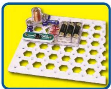
natural_image
White hexagonal grid board with electronic components and a small circuit board (no visible text or symbols)
Project #73
HYPNOTIC DISCS


WARNING: Moving parts. Do not touch the fan or motor during operation.

WARNING: Do not lean over the motor.
Try to make your own hypnotic disc!

natural_image
Blue cartoon character with numbered joints and a smiling face, no text or symbols presentEducational Corner:
When a person is hypnotized, some thinking capabilities of their mind are bypassed and they are in a new frame of thinking and perception. This can help them relax during medical procedures or other stressful times.
Assembly
Build the circuit as shown. Cut out the red spiral pattern shown and tape it on the fan.
Operation
Part A
Spin the pattern by briefly pushing the press switch (S2). You will see the most interesting effects when the pattern is spinning slowly. See if you can hypnotize someone into a trance.
Part B
Replace the pattern with the colored lines pattern shown. When the switch is pressed, the arcs turn into colored rings with a black background. Notice how the color drops when it is stretched to make a complete circle.
Part C
Place the circuit under a fluorescent light in your home and spin the disc slowly. As the speed changes, you may notice the lines first seem to move in one direction, then they start moving in another direction. This effect is because the lights are blinking 60 times a second and the changing speed of the motor is acting like a strobe light to catch the motion at certain speeds. This doesn't work with all fluorescent lights, due to differences in their circuitry.

natural_image
Two abstract diagrams: one showing a circular pattern divided into colored segments, the other a red spiral pattern enclosed by a dashed circle (no text or symbols)□ Project #74
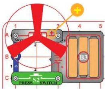
You are getting sleepy...

WARNING: Moving parts. Do not touch the fan or motor during operation.

WARNING: Do not lean over the motor.
Assembly
Build the circuit as shown (the same as the preceding project). Using the fan as a guide, draw a circle on a piece of cardboard or paper. Cut the circle out with scissors and tape it to the fan blade so it can be easily removed later. Obtain some thin and thick marking pens to use as drawing tools.
Operation
Spin the paper by pressing and holding the press switch (S2) down. Gently press the marker on the paper to form rings. To make spiral drawings, release the press switch and as the motor approaches a slow speed, move the marker from the inside outward quickly.
Change the colors often and avoid using too much black to get hypnotic effects. Another method is to make colorful shapes on the disc then spin the disc and watch them blend into each other.
Description
Spin Draw is an old toy that your parents may have played with when they were young.

natural_image
Concentric red spiral pattern enclosed in a dashed black circle (no text or symbols)
natural_image
Circular abstract pattern with six colored arcs (pink, blue, yellow, green, purple) on black background, no text or symbols present.SPIN DRAW
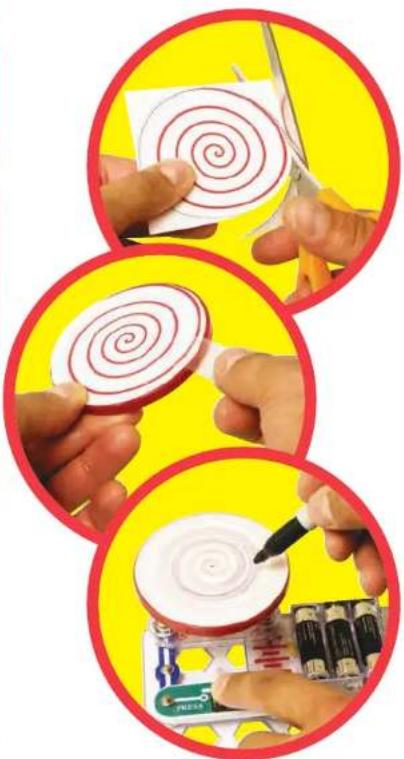
natural_image
Three circular images showing hands performing a spiral drawing process: one with a paper, one with a pen, and one with a battery pack (no text or symbols visible)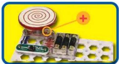
natural_image
Electronic circuit board with a spiral component and a plus sign, set against a yellow background (no readable text or symbols)
Project #75
MORSE CODE


Operation
This simple circuit can be used for communication.
Push the press switch (S2) in long and short bursts to make a pattern of light flashes representing the dots and dashes shown in the Morse Code table above. You can use Morse Code and this circuit to send secret messages to some friends in the room without others knowing what you're saying.
If you have a strong flashlight or searchlight then you can send messages to friends far away at night. During World War II Navy ships sometimes communicated by flashing Morse Code messages between ships using searchlights (because radio transmissions might reveal their presence to the enemy).

natural_image
White hexagonal grid device with a small electronic component mounted on top, set against a yellow background (no visible text or symbols)Educational Corner:
Morse Code: The forerunner of today's telephone system was the telegraph, which was widely used in the latter half of the 19th century. It only had two states - on or off (that is, transmitting or not transmitting), and could not send the range of frequencies contained in human voices or music. A code was developed to send information over long distances using this system and a sequence of dots and dashes (short or long transmit bursts). It was named Morse Code after its inventor. It was also used extensively in the early days of radio communications, though it isn't in wide use today. It is sometimes referred to in Hollywood movies, especially Westerns.
MORSE CODE
| A | . _ | N | . . | Period | . . . . _ | ||
| B | . . . | O | . . . | Comma | . . . . _ | ||
| C | . . . . | P | . . . . | Question | . . . . . . | ||
| D | _ | . | . Q | . . . . _ | 1 | . _ . . . . | |
| E | . | R | . . | 2 | . . _ . . | ||
| F | . . . . | S | . . | . | 3 | . . . . _ | |
| G | . . . | T | _ | 4 | . . . . _ | ||
| H | . . . . | U | . . | . | 5 | . . . . . | |
| I | . . | V | . . . . _ | 6 | . . . . . | ||
| J | . _ . . | W | . . . . _ | 7 | . . . . . | ||
| K | _ | . | X | . . . . _ | 8 | . . . . . . | |
| L | . . . . | Y | . . . . _ | 9 | . . . . . . | ||
| M | . . . | Z | . . . . . | 0 | . . . . . . |

Project #76


WARNING: Moving parts. Do not touch the fan or motor during operation.

WARNING: Do not lean over the motor. Fan may not rise until switch is released.
Snappy says: This circuit is similar to project 54 but may launch the fan a little higher. Project 54 has the slide switches and more blue snap wires; together these add a slight amount of additional resistance to the circuit.

natural_image
Cartoon stick figure with numbered limbs and a yellow base (no text or symbols)FLYING SAUCER
Assembly
Build the circuit as shown and place the fan on the motor (M1). Be sure the "+" side of the motor is on the left.
Operation
Push the press switch (S2) until the motor reaches full speed, then release it. The fan blade should rise and float through the air like a flying saucer. Be careful not to look directly down on fan blade when it is spinning. If the fan doesn't fly off, then turn the switch on and off several times rapidly when it is at full speed.

natural_image
White hexagonal grid device with a small electronic component and a red circular icon, set against a yellow background (no text or symbols visible)Description
The air is being blown down through the blade and the motor rotation locks the fan on the shaft. When the motor is turned off, the blade unlocks from the shaft and is free to act as a propeller and fly through the air. If speed of rotation is too slow, the fan will remain on the motor shaft because it does not have enough lift to propel it. The motor will spin faster when the batteries are new.

Project #77
POWER LIGHT REGULATOR


WARNING: Moving parts. Do not touch the fan or motor during operation.

WARNING: Do not lean over the motor.

natural_image
Electronic circuit board with components including batteries, switches, and a meter (no readable text or symbols)
natural_image
Illustration of a blue stick figure with numbered joints and a smiling face, standing on a yellow oval background (no text or symbols)Assembly
Build the circuit and set the meter (M5) to the 1A scale. Leave the fan off the motor (M1).
Operation
Push the press switch (S2); at least one lamp (L4) lights and the meter reads the current. The slide switches (S5) add the other lamp and motor to the circuit.
Educational Corner:
Now set the top slide switch to position C (disabling the motor) and the bottom slide switch to position B (enabling the second lamp). While holding down the press switch, flip the top slide switch to position B - the motor may need a push to start. Now release the press switch and push it again - the motor starts without a push.
Why can't the motor start as easily when the lamps are already on? The lamps have more resistance when they are bright, and the motor needs a higher current to start spinning. When the lamps start dark, more current flows until they warm up. This extra current enables the motor to get going.
Electric Paths
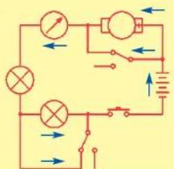

Project #78
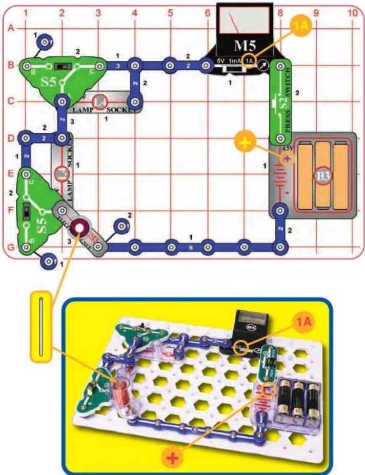
RAISING THE BAR
Assembly
Build the circuit as shown. Drop the thin rod into the electromagnet (M3). Set the meter (M5) to the 1A setting.
Operation
Push the press switch (S2) to suck the thin rod into the electromagnet. The meter measures the current.
The slide switches (S5) adjust the rod height and meter current a little.
Description
The slide switches add one or two lamps to the circuit, reducing the current through the electromagnet and meter.
Educational Corner:
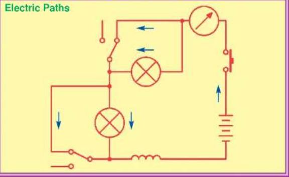

Project #79
ELECTROMAGNETIC PLAYGROUND
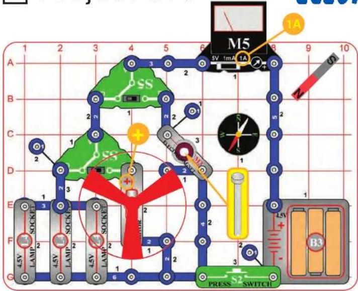

WARNING: Moving parts. Do not touch the fan or motor during operation.

WARNING: Do not lean over the motor.
Assembly
Build the circuit as shown, set the top slide switch (S5) to position C, place the fan on the motor (M1), place the iron core rod in the electromagnet (M3), set the meter (M5) to the 1A scale, and lay the magnet on the base grid in the spot shown (red side toward the compass).
Operation
Push the press switch (S2): either the lamps (L4) will light or the fan will spin, depending on the position of the lower slide switch.
Now, set the top slide switch to position C. When you push the press switch, the compass needle moves; when you release the switch, the compass returns to pointing toward the magnet. Hold down the press switch while moving the magnet closer to and then away from the compass, and watch how the compass needle points.
The meter always shows the current.
Description
The switches direct the electricity between the lamps, motor, and electromagnet. When activated, the electromagnet fights with the magnet for control of the compass needle.
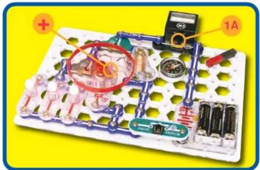

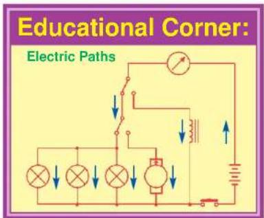
Notes
OTHER SNAP CIRCUITS® PRODUCTS!
Contact Elenco® to find out where you can purchase these products.
Snap Circuits® Model SC-300
Build over 300 projects
Including:
- AM radio
- Radio announcer
- Lie detector
- Burglar alarm
Contains over 60 parts
Including:
- Two transistors
- Microphone
- Power amplifier IC
- Variable capacitor
Snap Circuits® XP™

Model SCXP-50
Build your own micro-computer!
Build over 50 projects and have loads of fun learning how to create programs on your computer to operate Snap Circuits® XP™. No prior understanding of microcontrollers required. Projects include Clap Light, Photon Counter, Launch Pad, Data Logger, and more! Connect to your computer using a special snap USB cable. Contains over 40 programs ready for download and 40 parts.
Snap Circuits® Extreme Model SC-750

Build over 750 projects
Including:
- Strobe light
• Transistor AM radio
- Electromagnetism
- Rechargeable battery
Contains over 80 parts
Including:
- Solar cell
- Electromagnet
- Vibration switch
• Computer interface
Deluxe Snap Rover ^® Model SCROV-50

natural_image
3D cutaway view of a transparent robotic vehicle with visible internal components (no text or symbols)Features:
Disc shooter
Digital voice recorder
Music sounds
Goes forward & backward
Headlight
Red & blue side lights
Wireless remote control
Left & right turning control
Contains over 50 parts
Snap Circuits® Green Model SCG-125

Alternative Energy Kit
Build over 125 projects and have loads of fun learning about environmentally-friendly energy and how the electricity in your home works. Includes full-color manual with over 100 pages and separate educational manual. This educational manual will explain all the forms of environmentally-friendly energy including: geothermal, hydrogen fuel cells, wind, solar, tidal, hydro, and others. Contains over 40 parts.
Introducing: Snap Circuits® Apparel
Shopping Tote Bag - Black
Part # 6TOTEBAG1


natural_image
White hooded jacket with a small emblem, displayed on a mannequin (no text or symbols visible)Youth Hooded Sweatshirt - Gray (S, M, L)
Find more on our website: www.snapcircuits.net

Stonewashed
Black Cap
Part # 6CAPS1
SCBE-75 Snaptricity® Block Layout
Important: If any parts are missing or damaged, DO NOT RETURN TO RETAILER.
Call toll-free (800) 533-2441 or e-mail us at: help@elenco.com. Customer Service • 150 Carpenter Ave. Wheeling, IL 60090 U.S.A.
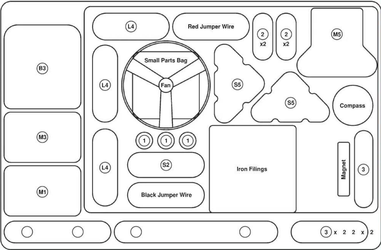
flowchart
graph TD
    A["Small Parts Bag"] --> B["L4"]
    A --> C["Fan"]
    A --> D["S5"]
    A --> E["S5"]
    A --> F["Compass"]
    A --> G["Iron Filings"]
    A --> H["Magnet"]
    A --> I["Black Jumper Wire"]
    A --> J["Red Jumper Wire"]
    A --> K["B3"]
    A --> L["M1"]
    A --> M["M3"]
    A --> N["M5"]


- Basic Troubleshooting
- WARNING:
- Batteries:
- Parts List (Colors and styles may vary) Symbols and Numbers
- How to Use It
- For Example:
- About Your Snaptricity® Parts
- BATTERY HOLDER PRES
- METER
- MOTOR
- ELECTROMAGNET
- LAMP
- OTHER PARTS
- DO's and DON'Ts of Building Circuits
- Here are some important guidelines:
- Examples of SHORT CIRCUITS - NEVER DO THESE!!!
- Advanced Troubleshooting (Adult supervision recommended)
- ELENCO®
- Project Listings
- Project # Description Page # Project # Description Page # Project # Description Page #
- Welcome to Electronics
- Static Electricity
- Electrical Materials
- Basic Electrical Circuits
- Putting Electricity to Use
- Magnetism
- Motor Circuits
- Advanced Magnetic Circuits
- Electrochemistry
- Fun with Electricity and Magnetism
- Project #1
- ELECTRONIC PLAYGROUND
- Assembly
- Operation
- Educational Corner:
- Project #2
- PARALLEL PLAY
- Description
- Project #3
- WICKED SWITCHES
- Project #4
- SPINNING CYLINDER SUSPENDER
- Project #5
- ELECTRICITY YOU CAN WEAR
- Project #6
- ELECTRICITY IN YOUR HAIR
- Do you want to learn more?
- Project #7
- BENDING WATER
- Project #8
- MORE STATIC TRICKS
- Electricity vs. Gravity:
- Project #9
- LIGHT THE WAY
- What is really happening here?
- Project #10
- FLIP IT
- Variant
- Project #11
- PUSHING ELECTRICITY
- Project #12
- PUSHING A LOT OF ELECTRICITY
- Project #13
- WHAT'S AN OHM?
- Project #14
- BE A SCIENTIST
- Project #15
- MAKE YOUR OWN PARTS
- □ Project #16
- HYDRO-RESISTORS
- Project #17
- ONE WAY AROUND
- Project #18
- MANY PATHS
- Project #19
- PARALLEL SWAPPING
- SERIES SWAPPING
- Project #21
- LIGHT BULB
- Project #22
- BATTERIES IN SERIES
- Project #23
- BATTERIES IN PARALLEL
- Project #24
- VOLTAGE DIVIDER
- Project #25
- VOLTAGE SHIFTER
- Project #26
- TRIPLE VOLTAGE DIVIDER
- Project #27
- TRIPLE SWITCHING VOLTMETER
- Project #28
- TRIPLE SWITCHING AMMETER
- Project #29
- CURRENT DIVIDER
- Project #30
- OHM'S LAW
- Project #31
- OHM'S LAW - COLD LAMP
- Project #32
- 2-WAY SWITCH
- Example:
- Project #33
- ANOTHER 2-WAY SWITCH
- Project #34
- 3-SPEED MOTOR
- Friction
- 3-SPEED MOTOR (II)
- □ Project #36
- 3-SPEED MOTOR (III)
- 3-POSITION SWITCH
- 3-POSITION SWITCH (II)
- Project #39
- 4-POSITION SWITCH
- Project #40
- AND
- Project #41
- AND NOT
- Project #42
- Project #43
- COMPASS
- Project #44
- MAGNETIC FIELDS
- Project #45
- IRON EXTENSION
- Project #46
- ELECTRONIC MAGNET
- Project #47
- ELECTROMAGNET MAGNETIC FIELD
- Project #48
- ELECTROMAGNET TOWER
- Project #49
- ELECTROMAGNETIC SUSPENDER
- Project #50
- ELECTROMAGNET DIRECTION
- Project #51
- WIRE MAGNET
- Notes:
- Project #52
- MAGNETIC INDUCTION
- Project #53
- Project #54
- PROPELLER AND FAN
- Project #55
- BACK EMF
- Project #56
- GENERATOR
- Project #57
- MAKE YOUR OWN GENERATOR
- Project #58
- STRING GENERATOR
- Project #59
- MOTION ENHANCER
- Project #60
- HOLDING DOWN
- Project #61
- MAKE YOUR OWN ELECTROMAGNET
- Project #62
- RELAY
- RELAY (II)
- Project #64
- FOR ADVANCED USERS - ADULT SUPERVISION RECOMMENDED
- RELAY (III)
- Project #65
- BUZZER
- BUZZER (II)
- Project #67
- REED SWITCH
- Project #68
- REED SWITCH (II)
- Project #69
- COLA POWER
- FRUIT POWER
- Project #71
- WATER IMPURITY DETECTOR
- Project #72
- INDIAN ROPE TRICK
- Project #73
- HYPNOTIC DISCS
- Part A
- Part B
- Part C
- □ Project #74
- SPIN DRAW
- Project #75
- MORSE CODE
- Project #76
- FLYING SAUCER
- Project #77
- POWER LIGHT REGULATOR
- Project #78
- RAISING THE BAR
- Project #79
- ELECTROMAGNETIC PLAYGROUND
- Notes
- OTHER SNAP CIRCUITS® PRODUCTS!
- Snap Circuits® Model SC-300
- Build over 300 projects
- Contains over 60 parts
- Snap Circuits® XP™
- Model SCXP-50
- Snap Circuits® Extreme Model SC-750
- Build over 750 projects
- Contains over 80 parts
- Deluxe Snap Rover ® Model SCROV-50
- Features:
- Snap Circuits® Green Model SCG-125
- Alternative Energy Kit
- Introducing: Snap Circuits® Apparel
- SCBE-75 Snaptricity® Block Layout
Brand : Snap Circuits
Model : Snaptricity SCBE-75
Category : Toy