
96210 - Vacuum Cleaner TORNADO - Free user manual and instructions
Find the device manual for free 96210 TORNADO in PDF.


| Product Type | Commercial Sweeper |
| Brand | Tornado |
| Model | 96210 |
| Machine Length | 80 cm (32 in) |
| Machine Height (handle folded) | 60 cm (24 in) |
| Machine Width | 70 cm (28 in) |
| Working Width | 66 cm (26 in) |
| Rotary Brush Width | 40 cm (16 in) |
| Rotary Brush Diameter | 19 cm (7 in) |
| Theoretical Area Coverage | 2400 m²/h (26000 sq ft/h) |
| Debris Container Volume | 40 L (9 gal) |
| Filter Surface | 1.1 m² (12 sq ft) |
| Nominal Voltage | 24 V |
| Power Consumption (Rotary Brush Drive) | 210 W / 8.75 A |
| Power Consumption (Side Brush Drive) | 48 W / 2 A |
| Power Consumption (Suction Turbine) | 60 W / 2.5 A |
| Weight without Batteries | 42 kg (93 lbs) |
| Weight with Batteries | 56 kg (124 lbs) |
| Noise Emission Level | 70 dB(A) ±2 dB(A) |
| Battery Type | Maintenance-free, 24V (4 batteries) |
| Integrated Battery Charger | Yes, automatic |
| Filter System | Filter with shaker; optional lint filter for carpets |
| Side Brush | Adjustable, replaceable |
| Rotary Brush | Segmented, replaceable |
| Handle Adjustment | Height adjustable via knurled screws |
| Safety Features | Grounded plug, drive bar safety switch, overload protection |
| Suitable Surfaces | Hard floors and carpets |
| Maximum Gradient | 2% (level surfaces only) |
| Warranty | See warranty registration form (commercial use) |
Frequently Asked Questions - 96210 TORNADO
User questions about 96210 TORNADO
0 question about this device. Answer the ones you know or ask your own.
Ask a new question about this device
Download the instructions for your Vacuum Cleaner in PDF format for free! Find your manual 96210 - TORNADO and take your electronic device back in hand. On this page are published all the documents necessary for the use of your device. 96210 by TORNADO.
USER MANUAL 96210 TORNADO
Operations & Maintenance Manual For Commercial Use Only
natural_image
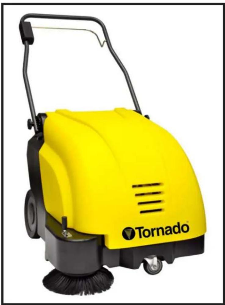
Yellow Tornado cleaning brush with black handle and brush, no visible text or symbols on the device itself.For warranty information go to www.tornadovac.com
GROUNDING INSTRUCTIONS
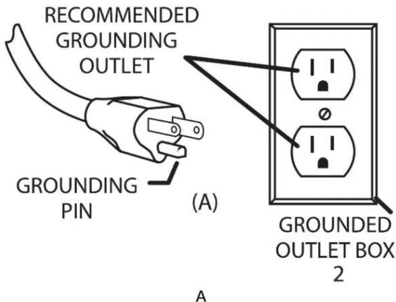
The battery charger for this appliance must be grounded. If it should malfunction or breakdown, grounding provides a path of least resistance for electric current to reduce the risk electric shock. The battery charger for this machine is equipped with a cord having an equipment -grounding conductor and grounding plug. The plug must be inserted into an appropriate outlet that is properly installed and grounded in accordance with all local codes and ordinances.
WARNING: Improper connection of the equipment-grounding conductor can result in a risk of electric shock. Check with a qualified electrician or service person if you are in doubt as to whether the outlet is properly grounded. Do not modify the plug provided with the appliance - if it will not fit the outlet, have a proper outlet installed by a qualified electrician.
This appliance is for use on a nominal 115-volt circuit, and has a grounding plug that looks like the plug illustrated in sketch A.

PROTECT THE ENVIROMENT
Please dispose of packaging materials in an environmentally safe way according to local waste disposal regulations.
Always remember to recycle.
Technical Data
| Machine length cm/in 80/32 | ||
| Machine height (handle folded) cm/in 60/24 | ||
| Machine width cm/in 70/28 | ||
| Working width cm/in 66/26 | ||
| Rotary brush width cm/in 40/16 | ||
| Rotary brush diameter cm/in 19/7 | ||
| Area Coverage, theoretical m2/sqft/h 2400/26000 | ||
| Debris Container Volume Liter/Gal 40/9 | ||
| Filter Surface m2/sqft 1.1/12 | ||
| Nominal Voltage V 24 | ||
| Power Consumption, rotary brush drive | W/A | 210/8.75 |
| Power Consumption, side brush drive | W/A | 48/2 |
| Power Consumption, suction turbine | W/A | 60/2.5 |
| Weight without batteries | kg/lbs. | 42/93 |
| Weight with batteries | kg/lbs. | 56/124 |
| Noise emission value* | dB (A) | 70 |
| Measurement inaccuracy (KpA): | dB (A) | 2 |
*The sound pressure level (LpA) (at the ear of the operator) measured according to DIN IEC 60335-2-72 under normal working conditions:
Your new Tornado unit is a high quality, precision-made product. All parts used in the manufacturing of this unit have passed rigid quality control standards prior to assembly. Please safeguard the original receipt / invoice. If you experience any problems with your unit during the warranty period, the original receipt / invoice will act as proof of purchase. Contact Tornado for any warranty inquiries.
IMPORTANT SAFETY INSTRUCTIONS
READ AND UNDERSTAND ALL INSTRUCTIONS BEFORE USING THIS UNIT
Read and understand this owner's manual and all labels on the unit before operating. Safety is a combination of common sense, staying alert and knowing how your unit works. Use this unit only as described in this manual. Use only manufacturer's recommended attachments. To reduce the risk of personal injury or damage to your unit use only Tornado recommended accessories.
1.1 Safety and Warning Symbols
All paragraphs in this manual referring to your personal safety, the safety of your machine and the environment protection are attributed one of the following warning symbols:
| Symbol Hazardous for Description | ||
| Safety Provisions Persons and goods Safety Provisions in dangerous situation caused by misuse inaccurate adherence of instructions or prescribed work routine. | ||
| CAUTION The machine Important information on handling the machine in order to maintain operability. | ||
| Ecological hazard The environment Due to use of substances representing an inherent danger to health of environment | ||
1.2 General information
• In addition to the information provided
- Before starting up the machine for the first time, read the operating manual supplied with it thoroughly as well as any separate manuals provided with additional or attachment devices and observe all the information during work.
- The equipment may only be operated, serviced and repaired by personnel trained in the operation of its use.
- Particular attention should be paid to the information regarding safety. Technical expertise is the key to preventing errors
- When operating the machine and ensuring trouble-free operation.
- The operating manual must always be kept at the operating location of the machine and, as a result, should be kept in a safe place on the equipment.
- The warning labels attached to the machine provide important information concerning safe operation. Illegible or missing labels must be replaced by new ones.
- For reasons of safety, always use original spare parts
1.3 Operating information
- Before starting the machine up for the first time, the battery to be used must be fully charged, properly, by implementing the initial battery charge routine. Please pay attention to the operating manual provided with the charging unit as well as the manual from the battery manufacturer. Tornado assumes no liability for damage to the battery caused by a fault when the battery is charged for the first time.
- Check the operational safety of the machine each time before starting it up! Clear any faults immediately!
- Before starting work, the operator must be fully familiar with all adjustment, operating and control elements as well as their respective function! It is too late to do this when the machine is actually in operation!
• Always wear heavy duty, non-slip footwear when working with the machine. - The machine may only be used on those surfaces which have been approved by the contractor or person appointed by him.
- When using the machine, it is essential to pay attention to third parties, especially children.
- Accelerate the machine immediately after switching on the brush head drive, otherwise imprints of the brush could be produced.
- The machine is not suitable for clearing up hazardous, inflammable or explosive fluids, dust or substances.
- It is forbidden to use the machine in potentially explosive atmospheres.
- The side brush must be raised in order to transport the machine.
- The machine has been conceived for use on level surfaces with a maximum gradient of 2% .
1.4 Maintenance information
- Operating personnel must complete the necessary daily and weekly maintenance work. All other maintenance work must be completed at your local Tornado authorized service center.
- The maintenance work and maintenance intervals prescribed in the operating manual must be adhered to.
- Suitable tools must be used for cleaning and maintenance work.
- The machine must be inspected by a recognized technical expert in respect of operational safety, within the terms of the applicable accident prevention laws, at reasonable intervals (we recommend at least once a year) and following modification or repairs.
- Spare parts must comply with the minimum technical requirements stipulated by the manufacturer! This is ensured by the use of original spare parts.
- The machine must be switched off prior to cleaning or servicing it or to replacing parts. The drive bar must be out of operation!
• Always disconnect the battery plug before starting any work on the electrical installation. - When working in the area of the raised hood, it must be hinged open fully to prevent it being knocked shut or further open and down unintentionally.
- It is not permitted to clean the machine with a pressure washer or steam blaster.
- It is not permitted to use aggressive and corrosive cleaning agents.
- Allow the machine to dry after being cleaned, e.g. over the weekend.
- Only start the machine up when all the safety equipment has been installed and brought to its protecting position.
1.5 Particular risks
Electronics
- In the case of defects in the electrical installation, switch the machine off immediately and clear the fault.
• Work on the electrical equipment may only be carried out by electricians who have received the necessary training - The machine's electrical equipment must be inspected/checked at regular intervals. Defects, such as loose connections and cable damage, must be rectified immediately.
Batteries
- It is possible that sparking will occur when connecting the batteries.
- Batteries may only be handled and changed by properly skilled maintenance personnel.
- The machine has been set up for operation using maintenance-free batteries. If other battery types are used, the machine must be set up for use with them by an authorized Tornado service center.
- Never lay any metallic objects or tools on batteries - risk of short circuit!
1.6 Environmental protection
- A certain factual expertise is required in order to use substances which could represent a risk to health and the environment.
- Observe the applicable laws and local regulations when disposing of waste.
- Used batteries with the recycling symbol contain reusable commodities. In accordance with symbol with the crossed out bin, these batteries must not be disposed of in domestic waste.
1.7 Labels on the machine
The following safety and warning labels are attached to the machine where easily legible. Missing or illegible labels must be replaced immediately.
Company logo

TORNADO
Rating plate
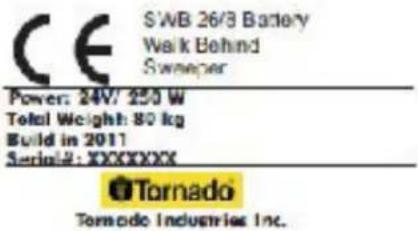
Read and observe the operating manual

Maximum permissible gradient

Filter shaker
Wear compensator for side brush

Wear compensator for rotary brush

2 Starting Up
2.1 Unpacking and assembling Fig 1
Open the box, two people are required.
To remove the machine from the protective wrap and place it on the floor.
- To fix the side brush (Fig 1/1) align the drive pins on the side brush drive plate and secure with the wing bolt and washer supplied.
- Loosen the two knurled screws (Fig. 1/2) holding the handle a few revolutions until the handle can be raised and positioned. Set the handle to a height comfortable for the user and then tighten the knurled screws.
- Remove the locking bolt (Fig 1/3) holding the hood and pivot the hood open.
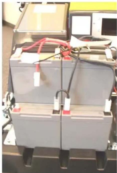
- Fix the disassembled cable lug (Fig. 2) to the corresponding battery contact. It is possible that sparking will occur when connecting the batteries!
- Close the hood and lock in place with the bolt.
- The unit is now ready to operate.
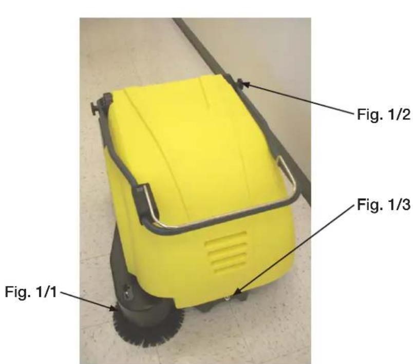
Fig. 1
natural_image
Exterior view of a battery system with red and black cables, no visible text or symbolsFig. 2
2.2 Instruction
Instructions to operators are required before putting the machine into service.
Only technicians from your local, authorized Tornado dealer are allowed to provide initial instruction on how to use the machine.
2.3 Initial battery charge

Before starting the machine up for the first time, the batteries to be used must be fully charged, properly, by implementing the initial battery charge routine.
2.4 Prior to starting up
Carry out the following checks before starting the machine:
- Check the charge status of the batteries.
- Check the levels of wear on the rotary brush and side brush.
- Check the fill level of the debris container.
2.5 Operation
Please read the Safety Information in Chapter 1. Before switching the machine on, ensure that the drive bar (Fig. 3/3) on the handle has not been actuated.
- Switch the machine on using the (Fig. 3/1) button: rotary brush drive, dust vacuum and side brush drive are ready to operate.
-
Lower the side brush to its working position using the lever (Fig. 3/4). When working without the side brush: do not lower the side brush and press the button (Fig. 3/2) for the side brush once. The green control lamp goes out.
-
Actuate the drive bar (Fig. 3/3) on the handle: the machine starts to work.

Start work immediately after actuating the drive bar, otherwise imprints could be produced on the floor. Release the drive bar when driving over thresholds.
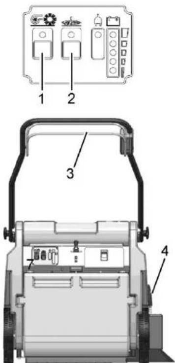
Fig. 3
2.6 Stopping the machine
When the drive bar is released, the rotary brush drive, dust vacuum and side brush drive switch off automatically.
2.7 After completing work
- Drive to an appropriate maintenance area.
- Stop the machine. Raise the side brush to its idle position and switch the machine off.
- Actuate the filter shaker.
- Empty the debris container.
- Check the brush space for accumulations of dirt.
- Check the charge status of the batteries.

It is not permitted to clean the machine with a pressure washer or steam blaster.
3 Operation
3.1 Method of operation
The Tornado SWB 26/8 is a machine designed to sweep and clean waste from hard floors and carpets. The side brush (Fig. 4/1) sweeps the dirt from corners to a position in front of the rotary brush (Fig. 4/2). The rotary brush sweeps the larger particle dirt overhead into the debris container (Fig. 4/3). The finer dust picked up is drawn up by the suction turbine, fed into the filter system (Fig. 4/4) and filtered out. Only dust-free air is fed back into the ambient air. The machine is equipped with maintenance- free batteries (Fig. 4/5), a specially adapted, fully automatic battery charger (Fig. 4/6) and a total discharge signal transducer to protect it against total discharge.
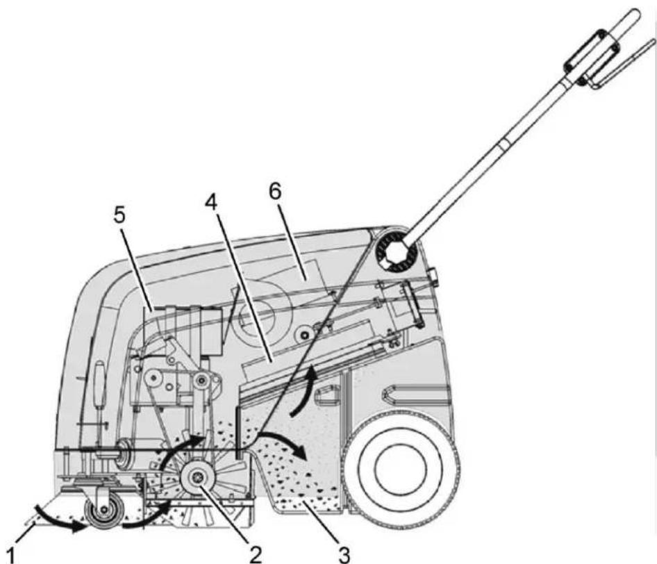
Fig. 4
3.2 Operating and indicator elements
3.2.1 Operating panel
- Control lamp for rotary brush drive, side brush drive and suction turbine
- ON/OFF button for rotary brush drive, side brush drive and suction turbine
- Control lamp for side brush drive
- ON/OFF button for side brush drive
- Control lamp for battery charger operation
- Charge control indicator
- Drive bar
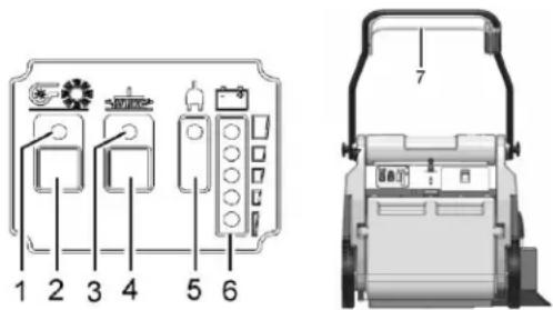
Fig. 5
ON/OFF button for rotary brush, side brush and suction turbine (Fig. 5/1).
The button activates the rotary brush drive, side brush drive and suction turbine so they are ready to operate. The side brush drive can be switched off separately. The suction turbine cannot be switched off separately which prevents the dust vacuum being activated by accident.

To prevent unauthorized use of the machine, be sure to switch the machine off using the button (Fig. 5/1).
Control lamp for rotary brush drive, side brush drive and suction turbine (Fig. 5/2).
The green control lamp indicates that the rotary brush drive and suction turbine are ready to operate. If the rotary brush or suction turbine is overloaded, a safety shutdown is triggered and the control lamp flashes.
ON/OFF button for side brush drive (Fig. 5/3).
The button can be used to switch off the side brush drive independently of the rotary brush drive and to activate it for use again.
Control lamp for side brush drive (Fig. 5/4).
The green control lamp indicates that the side brush drive is ready to operate. If the side brush is overloaded, a safety shutdown is triggered and the control lamp flashes.
Control lamp for battery charger operation (Fig. 5/5).
This control lamp indicates that the batteries are being charged
Charge control indicator (Fig. 5/6).
During the charging process, the machine's electronics system controls the machine is not switched on inadvertently and indicates the charge status. The battery charge status is indicated by 4 green and 1 red LED.
The battery voltage is depicted in 5 levels:
25.1 V = all green LEDs on
24.5 V = bottom 3 green LEDs on
23.9 V = bottom 2 green LEDs on
22.7 V = bottom green LED on
< 22.7 V = red battery LED flashes
Drive bar (Fig. 5/7).
The drive bar switches all the drives which are ready to operate on or off.
The drive bar serves to prevent damage. If the drive bar is released during operation, all the drives are switched off
3.2.2 Operating elements on the machine
Knurled screws for handle (Fig. 6/1).
The two knurled screws enable the handle to be adjusted to a comfortable height for the user.
Shaking device lever (Fig. 6/2).
In order to clean the filter in the dust vacuum, switch the shaking device lever several times quickly to the left and right.
Debris container locks (Fig. 6/3).
Pull the lock lever up in order to remove the debris container.
Side brush lever (Fig. 6/4).
Use the lever to lower or raise the side brush.
Charger cable flap (Fig. 6/5).
The battery charger cable is located behind the flap to the right beside the operating panel. Pull the lock downwards to open the flap.
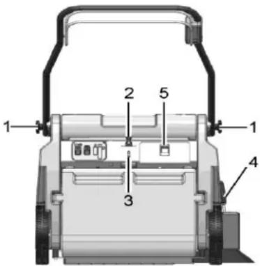
Fig. 6
5 Maintenance and Service
General information
It is essential to pay attention to the information in Chapter "Safety Information" before completing any service or maintenance work!
By adhering to the maintenance work recommended by us, you can be sure that the machine is always ready to be put into operation.
Maintenance and repair work necessary on a daily and weekly basis can be carried out by an operator trained to complete the work, all other Tornado system maintenance may only be completed by personnel who are correspondingly qualified and trained.
Please contact your nearest Tornado service center or Tornado authorized dealer.
Failure to observe this annuls any rights to claims under the terms of guarantee in respect of resulting damage or consequential damage.
Always specify the serial number in the case of inquiries and spare parts orders, refer to section
1.7 - Rating plate.
5.1 Maintenance Plan
System maintenance, customer
The following maintenance work must be completed by the customer at the intervals stipulated.
| Activity Interval | ||
| Daily | Weekly | |
| Check the battery charge; recharge if necessary X | ||
| Empty the debris container X | ||
| Clean the brush space X | ||
| Check the filter in the dust vacuum; clean, if necessary X | ||
| Check the rotary brush and side brush; clean, if necessary X | ||
| Check the sweeping pattern; readjust, if necessary X | ||
| Check the sealing strips on the rotary brush for signs of wear; clean, if necessary | X | |
| Check the gasket on the debris container X | ||
| Check the function of the suction turbine X | ||
| Check the debris container lock X | ||
| Test drive and function test X | ||
5.2 Battery system
- Battery indicator for charger
- Charge control indicator
- Charger
- Flap for charger mains power cable
- Connection cable
- Lashing straps
- Batteries
- Hood
- Connection plan
Batteries may only be handled and changed by properly skilled maintenance personnel. The charge control indicator (Fig. 7/2) indicates the charge status of the batteries during operation. When the batteries are discharged, the red LED flashes. The machine functions are restricted. Charge the batteries immediately!
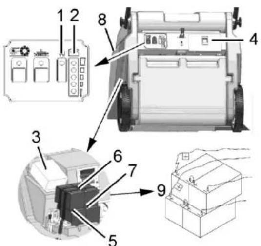
Fig. 7
5.2.1 Charging batteries
The charge control indicator (Fig. 7/2) indicates the charge status of the batteries during operation. The batteries must be charged immediately when the red LED lights up. The batteries (Fig. 7/7) are charged using the integrated battery charger (Fig. 7/3). The charger is connected by means of the power cable (Fig. 7/4).
While the battery is being charged, the battery indicator on the charger (Fig. 7/1) lights up.

Before starting the machine up for the first time, the batteries to be used must be fully charged, properly, by implementing the initial battery charge routine. Tornado assumes no liability for damage to the battery caused by a fault when the battery is charged for the first time.
5.2.2 Total discharge signal transducer (TSG)
The machine is equipped with a total discharge signal transducer to protect the batteries against total discharge. The total discharge signal transducer is integrated in the electronics.
5.2.3 Servicing the driving batteries
Never leave discharged batteries lying around; recharge them immediately!
5.2.4 Removing the batteries
- Park the machine on a level area of floor.
- Switch off the machine.
- Loosen the locking bolt holding the hood (refer to Figure 1/3) and pivot the hood open.
- Slacken the lashing straps (Fig. 7/6).
- Disconnect the connection cable (Fig. 7/5) from the batteries and remove the batteries.
5.2.5 Inserting the batteries

Only the special batteries approved by Tornado may be installed at the prescribed position.
- Install the two lower batteries in the battery holder in accordance with Figure 7.
- Lay the rubber mat on the batteries.
- Place the other two batteries on the rubber mat.
- Tighten the lashing straps (Fig. 7/6).
- Connect the battery poles to the connection cables in accordance with the connection plan (Fig. 7/9). It is possible that sparking will occur when connecting the batteries! Check to ensure a firm fit!
- Close the hood (Fig. 7/8) and lock in place with the locking bolt on the frame.
5.2.6 Disposing of batteries
Used batteries with the recycling symbol contain reusable commodities. In accordance with symbol with the crossed out bin, these batteries must not be disposed of in domestic waste.
5.3 Side brushes
- Side brushes
- Wing bolt
- Carrier
- Hood
- Adjusting bolt
- Counternut
- Locking bolt
5.3.1 Changing the side brush
Check the side brush (Fig. 8/1) weekly and change in the case of wear.
- Switch the machine off and lay it on its side.
- Remove the wing bolt (Fig. 8/2) with the washer from underneath the side brush (Fig. 8/1).
- Pull the side brush off.
- To fix the side brush align the drive pins on the side brush drive plate and secure with the wing bolt and washer supplied.
5.3.2 Setting the sweeping pattern
In the case of brush wear and after changing the side brush (Fig. 8/1), readjust the sweeping pattern.
- Switch the machine off; unscrew the locking bolt (Fig. 8/7) and open the hood (Fig. 8/4).
- Loosen the countennut (Fig. 8/6) and adjust the sweeping pattern by turning the adjusting bolt (Fig. 8/5) clockwise and counter clockwise so that it touches the floor.
- Tighten the counternut again and close the hood.
- Switch the machine on and allow the side brush to run while standing still for a short time.
- Switch the machine off, raise the front a little and pull it back.
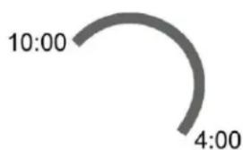
- Check the sweeping pattern, comparing it with a clock viewed driving forward. When set correctly, the sweeping pattern must make an impression on the floor between approx. 10:00 and 4:00 o' clock (Fig. 9).
- Repeat the process, if necessary, until the sweeping pattern is set correctly.
- Close the hood (Fig. 8/4) and screw the locking bolt (Fig. 8/7) back in.
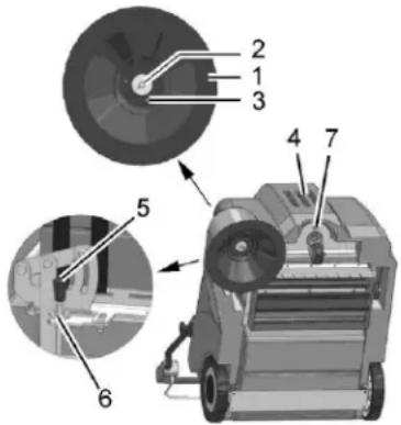
Fig. 8
gauge
| Time | Value | |---|---| | 10:00 | 10:00 | | 4:00 | 4:00 |Fig. 9
5.4 Rotary brush
- Rotary brush
- Fillister head self-tapping screws
- Rotary brush segment
- Sealing strips
- Sweeping pattern adjusting lever
- Timing belt
- Hood
- Locking bolt
5.4.1 Cleaning the brush space
The brush space with rotary brush (Fig. 10/1) and gaskets (Fig. 10/4) must be checked daily for signs of dirt and cleaned, if necessary.
5.4.2 Changing the rotary brush
The rotary brush (Fig. 10/1) must be checked weekly and changed in the case of wear.
- Switch the machine off and lay it on its side.
- Loosen the six screws (Fig. 10/2) in the rotary brush and remove the two roller segments.
- Install the two new roller segments and fix in place with the fillister head screws.
- After changing the rotary brush, readjust the sweeping pattern as necessary.
5.4.3 Setting the sweeping pattern
In the case of brush wear, and after changing the rotary brush (Fig. 10/1), readjust the sweeping pattern.
- Switch the machine off, unscrew the locking bolt (Fig. 10/8) and open the hood (Fig. 10/7).
- Loosen the wing nut on the adjusting lever (Fig. 10/5) and adjust the sweeping pattern using the adjusting lever by pivoting it up and down until it touches the floor.
- Tighten the wing nut again and close the hood.
- Switch the machine on and allow the rotary brush to run while standing still for a short time.
- Switch the machine off, raise the front a little and pull it back.
- When adjusted correctly, there must be an approx. 50 mm wide sweeping pattern on the floor which has parallel sides.
-
Repeat the process, if necessary, until the sweeping pattern is set correctly.
-
Close the hood (Fig. 10/7) and screw the locking bolt (Fig. 10/8) back in
5.4.4 Changing the sealing strips
The four sealing strips (Fig. 10/4) must be checked weekly and changed in the case of wear.
- Switch the machine off and lay it on its side.
- Remove all four sealing strips (Fig.10/2) with holders.
- Loosen the screws in the holders and remove the damaged sealing strips.
- Fix the new sealing strips on the holders and reinstall them.
- Adjust the sealing strips so that they touch the floor lightly.
5.4.5 Changing the timing belt
The timing belt (Fig. 10/6) must be checked every 500 operating hours and changed in the event of wear.
- Switch the machine off, unscrew the locking bolt (Fig. 10/8) and open the hood (Fig. 10/7).
- Slacken the timing belt (Fig. 10/6) using the tension pulley and remove the belt.
- Slacken the tension pulley and install the new timing belt. The timing belt is automatically tensioned by means of a tension spring.
- Close the hood (Fig. 10/7) and screw the locking bolts (Fig. 10/8) back in.
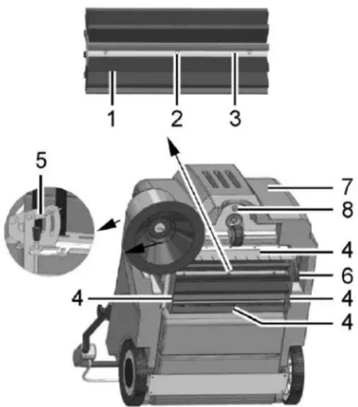
Fig. 10
5.5 Debris container
1 Debris container
2 Locking mechanism
3 Seal
4 Handle
5.5.1 Emptying the debris container
Check the fill level of the debris container (Fig. 11/1) at regular intervals (max. load capacity 25 kg) and empty as necessary.
- Switch the machine off and pull the locking mechanism (Fig. 11/2) on the debris container (Fig. 11/1) upwards.
- Pull the debris container to the rear out of the machine using the handle (Fig. 11/4) and dispose of the waste according to the applicable environmental laws.
- Reinstall the debris container and press it against the locking mechanism until it audibly latches into place.
5.5.2 Changing the seal
Check the seal (Fig. 11/3) weekly for signs of wear and change it as necessary.
- Switch off the machine and pull the locking mechanism (Fig. 11/2) on the debris container (Fig. 11/1) upwards.
- Pull the debris container (Fig. 11/3) out of the machine using the handle (Fig. 11/4).
- Pull the seal for the debris container from the filter support frame. Install a new seal.
- Reinstall the debris container.
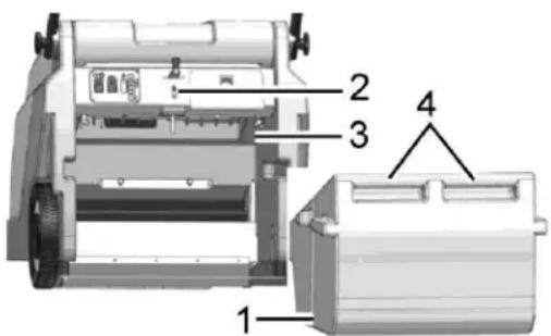
Fig. 11
5.6 Dust vacuum
1 Filter
2 Sealing strip
3 Filter support frame
4 Shaking device
5 Wing bolts
6 Holders
5.6.1 Cleaning the filter
Clean the filter (Fig. 12/1) in the dust vacuum as necessary using the shaking device (Fig. 12/4). In the case of extreme accumulation of dirt, clean the filter as follows:
- Switch the machine off and remove the debris container.
- Loosen the wing bolts (Fig. 12/5). Pivot the filter support frame (Fig. 12/3) down and remove it.
- Remove the filter from the filter support frame.
Beat the filter clean or use a vacuum cleaner. Be careful not to damage the filter ribs! - Insert the correct side of filter in the filter support frame. The sealing strip (Fig. 12/2) must point towards the suction turbine!
- Hook the filter support frame in the holder (Fig. 12/6) and fix in place with the wing bolts.
- Reinstall the debris container
5.6.2 Changing the filter
Check the filter (Fig. 12/1) every 250 operating hours for signs of wear and change it as necessary.
- Switch the machine off and remove the debris container.
- Unscrew the wing bolts (Fig. 12/5). Pivot the filter support frame (Fig. 12/3) downward and remove it.
- Remove the filter from the filter support frame.
- Insert the correct side of the new filter in the filter support frame. The sealing strip (Fig. 12/2) must point towards the suction turbine!
- Hook the filter support frame in the holder (Fig. 12/6), if necessary, and fix in place with the wing bolts.
- Reinstall the debris container
5.6.3 Install the Lint filter
If the machine is mainly used on carpet, you have to install the lint filter (Fig.13/7).
- Switch the machine off and remove the debris container.
- Unscrew the wing bolts (Fig.12/5). Pivot the filter support frame (Fig.13/3) down and remove it.
- Mount the lint filter (Fig.13/7) between filter and the filter support frame
- Hook the filter support frame in the holder (Fig.12/6), if necessary, and fix in place with the wing bolts.
- Reinstall the debris container.
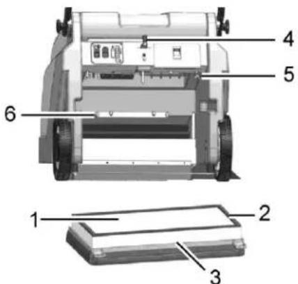
Fig. 12
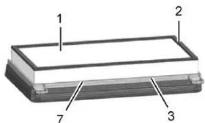
Fig. 13

TORNADO®
Warranty Registration Form
Please Print Clearly
| Company/Institution | |
| Contact Name | Title |
| Address | City/State/Zip Code |
| Phone | Fax |
| Date of Purchase | |
| Selling Dealer:(Required) | |
See white metal plate or sticker on unit for this information.
| MACHINE TYPE/MODEL NUMBER: MACHINE | SERIAL NUMBER: |
| 1. 1. | |
| 2. 2. | |
| 3. 3. | |
| 4. 4. |
Facility Description (please circle all that apply)
- School 6. Manufacturing 11. Airport 16. Other Govt.
- Retail Store 7. College/University
- Restaurant 8. Hospital
- Office Building 9. Nursing Home
-
Contract Cleaning 10. Religious Institution
-
Warehouse 17. Auto Service
- Apartment/Condo 18. Non-Profit
-
Supermarket 19. Other (specify)
-
U.S. Govt
How did you first learn about Tornado cleaning and maintenance equipment?
- Contacted by local dealer
- Previous experience with Tornado products
- Reputation/Recommendation
○ Advertising - Direct mail
Website:
○ Blog: ____
○ Other
You can complete this form online at
www.tornadovac.com/services/warranty-registration-form.aspx
This form may also be returned to :
Tornado Industries
3101 Wichita Court
Fort Worth, TX 76140
Fax: 817-551-0719
Damage or defect arising from abuse, neglect or other misuse is excluded from this warranty. Other items may or may not apply based on your specific machine. If any defect occurs, and service is attempted by non-Authorized Tornado Service Centers, the warranty will be void.
- GROUNDING INSTRUCTIONS
- PROTECT THE ENVIROMENT
- IMPORTANT SAFETY INSTRUCTIONS
- READ AND UNDERSTAND ALL INSTRUCTIONS BEFORE USING THIS UNIT
- Safety and Warning Symbols
- General information
- Operating information
- Maintenance information
- Particular risks
- Electronics
- Batteries
- Environmental protection
- Labels on the machine
- Starting Up
- Unpacking and assembling Fig 1
- Instruction
- Initial battery charge
- Prior to starting up
- Operation
- Stopping the machine
- After completing work
- Operation
- Method of operation
- Operating and indicator elements
- Operating panel
- Operating elements on the machine
- Maintenance and Service
- - Rating plate.
- Maintenance Plan
- Battery system
- Charging batteries
- Total discharge signal transducer (TSG)
- Servicing the driving batteries
- Removing the batteries
- Inserting the batteries
- Disposing of batteries
- Side brushes
- Changing the side brush
- Setting the sweeping pattern
- Rotary brush
- Cleaning the brush space
- Changing the rotary brush
- Setting the sweeping pattern
- Changing the sealing strips
- Changing the timing belt
- Debris container
- Emptying the debris container
- Changing the seal
- Dust vacuum
- Cleaning the filter
- Changing the filter
- Install the Lint filter
- TORNADO®
- Warranty Registration Form
- Facility Description (please circle all that apply)
- How did you first learn about Tornado cleaning and maintenance equipment?
- You can complete this form online at
Brand : TORNADO
Model : 96210
Category : Vacuum Cleaner