
TRDA523028 - Temperature regulator JUNG - Free user manual and instructions
Find the device manual for free TRDA523028 JUNG in PDF.


| Product Type | Temperature Regulator |
| Brand | JUNG |
| Model | TRDA523028 |
| Dimensions (H x W x D) | 80 x 80 x 30 mm |
| Weight | 150 g |
| Power Supply | 230 V AC, 50/60 Hz |
| Power Consumption | < 2 W |
| Temperature Range | 5°C to 35°C |
| Control Type | Electronic thermostat with rotary setpoint adjuster |
| Display | None (mechanical or simple indicator) |
| Functions | Temperature control, heating/cooling mode selection, frost protection |
| Protection Class | IP20 |
| Installation | Wall-mounted, flush or surface |
| Certifications | CE, RoHS |
| Operating Temperature | 0°C to 50°C |
| Storage Temperature | -20°C to 60°C |
| Maintenance | Clean with a dry, soft cloth. Do not use harsh chemicals. |
| Safety Instructions | Installation by qualified electrician. Disconnect power before maintenance. |
| Spare Parts | No user-serviceable parts. Contact JUNG service for replacement. |
| Warranty | 2 years from date of purchase |
Frequently Asked Questions - TRDA523028 JUNG
User questions about TRDA523028 JUNG
0 question about this device. Answer the ones you know or ask your own.
Ask a new question about this device
Download the instructions for your Temperature regulator in PDF format for free! Find your manual TRDA523028 - JUNG and take your electronic device back in hand. On this page are published all the documents necessary for the use of your device. TRDA523028 by JUNG.
USER MANUAL TRDA523028 JUNG
Temperature controller fan coil, 2-pipe
Art. no.: TRDA523028..
Temperature controller fan coil, 2-pipe
Art. no.: TRDLS923028..
Temperature controller fan coil, 4-pipe
Art. no.: TRDA523048..
Temperature controller fan coil, 4-pipe
Art. no.: TRDLS923048..
Operating instructions
1 Safety instructions

Electrical devices may only be mounted and connected by electrically skilled persons.
Serious injuries, fire or property damage possible. Please read and follow manual fully.
These instructions are an integral part of the product, and must remain with the end customer.
2 Intended use
- Switching and operating electrical fan coil units with electrothermically actuated heating/cooling valves
– Measurement and feedback control of the room temperature
– Mounting in appliance box according to DIN 49073
These instructions contain information on the mounting, installation and the commissioning of the product. The detailed instructions on our website contain information on the function of the device and the setting of setpoints.
Product characteristics
- Connection of one fan coil unit with up to 3 fan stages
- Operating modes for heating, cooling or combined heating/cooling operation
– Variants for 2-pipe or 4-pipe operation - 8 capacitive sensor buttons
- Internal temperature sensor
– Room temperature controller function
– Preselection of the current energy level through the option of 5 temperature profiles for use in hotels or similar sites - Display for indication of temperature (°C or °F), fan level, operating mode/profile
- Menu levels blockable
- 1 status LED (red/green/blue)
– Brightness and contrast adjustable - Switch-off time of the display illumination up to 120 seconds
- Extension input to the connection of, e.g. hotel card switch (see accessories)
3 Function
Intended use
- Switching and operating electrical fan coil units with electrothermically actuated heating/ cooling valves
– Measurement and feedback control of the room temperature
– Mounting in appliance box according to DIN 49073
Product characteristics
- Connection of one fan coil unit with up to 3 fan stages
- Operating modes for heating, cooling or combined heating/cooling operation
– Variants for 2-pipe or 4-pipe operation - 8 capacitive sensor buttons
– Internal temperature sensor
– Room temperature controller function
– Preselection of the current energy level through the option of 5 temperature profiles for use in hotels or similar sites - Display for indication of temperature (°C or °F), fan level, operating mode/profile
- Menu levels blockable
- 1 status LED (red/green/blue)
– Brightness and contrast adjustable - Switch-off time of the display illumination up to 120 seconds
- Extension input to the connection of, e.g. hotel card switch (see accessories)
4 Operation
Operating elements
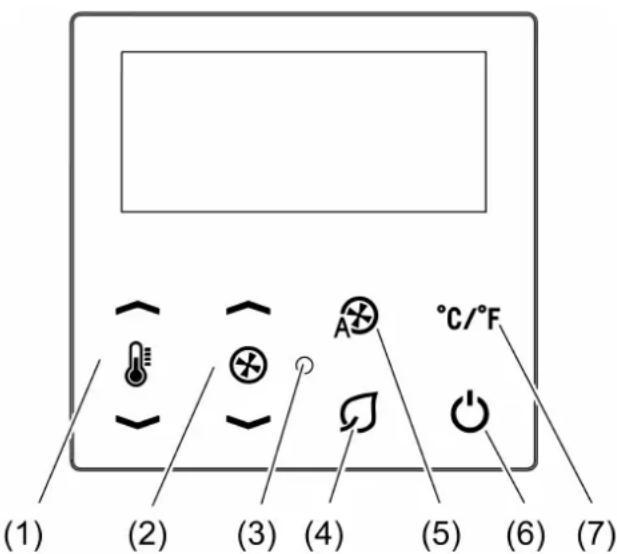
Figure 1: View
(1) Temperature setpoint adjustment

(2) Manual setting of the fan stage Ⓧ

(3) Status LED
(4) Switchover to the Eco profile
(5) Fan stage automatic mode Ⓧ
(6) Switchover to the Standby ⏻ profile
(7) Switchover of the temperature display Celsius/Fahrenheit ^ C/ ^ F
Status LED
The status LED shows the current operating mode of the controller or the actuation of the sensor buttons or both.
| LED colour Profile | |
| Green or off Comfort, comfort-, eco | |
| Red or off Standby, building protection |
Green flashing signals actuation of the sensor buttons.
Open menu level 1
Only for heating and cooling mode with manual switchover. In systems that are intended solely for heating or cooling menu level 1 is not available.
■ Press the sensor buttons ⏻ and ⭊ between 2 and 4 seconds.
Open menu level 2
■ Press the sensor buttons ⏻ and Ⓗ longer than 5 seconds.
Operating in the menu
■ Increase value: press sensor button 🔊.
■ Reduce value: press sensor button ⏻.
■ Select previous menu item: press Ⓧ sensor button.
■ Select next menu item: press Ⓧ sensor button.
■ Exit menu without saving: press sensor button (✗) (✗)
■ Save settings and exit menu: Press the °C/°F sensor button. (√)
5 Operation
Setpoints for room temperature and fan stage – Profiles
The selection of the current setpoints for room temperature and fan stage is based on so-called profiles that are specified by the user on site. The following situations are covered, e.g.:
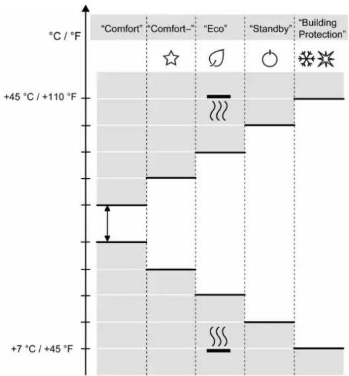
bar
| Temperature | Condition | Value | |---|---|---| | +45 °C / +110 °F | Comfort | | | +45 °C / +110 °F | Comfort- | | | +45 °C / +110 °F | Eco | | | +45 °C / +110 °F | Standby | | | +45 °C / +110 °F | Building Protection | | | +7 °C / +45 °F | Comfort | | | +7 °C / +45 °F | Comfort- | | | +7 °C / +45 °F | Eco | | | +7 °C / +45 °F | Standby | | | +7 °C / +45 °F | Building Protection | |Figure 2: Temperature setpoints for heating and cooling for the individual profiles
- "Comfort" profile:
The hotel room is occupied, the hotel guest is present. The room temperature is set to a comfortable value.
- "Comfort-" profile ☆ (if a hotel card switch is installed):
The hotel guest is not present. The setpoints are set to an energy saving level; the values of the "Comfort" profile can be reached quickly.
As soon as a hotel guest inserts the hotel card into the available hotel card switch, the controller switches to the "Comfort" profile.
- "Eco" profile ∅:
It is night, the controller controls the connected fan coil units and puts them into an energy-saving and silent operation.
- "Standby" profile ⏻:
Currently the room is not in use. The energy level is set such that only minimum heating/air conditioning costs are incurred by the owner.
- "Building Protection" profile ✦ ✦:
When the environment raises or lowers the room temperature to a level that could damage the building, the controller automatically activates the building protection operation.
The setpoint temperatures are permanently set (heating: +7 °C; cooling: +45 °C).
Operating elements
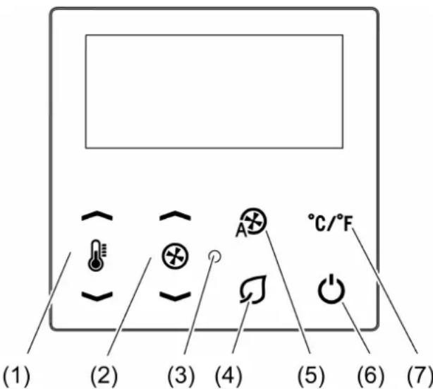
Figure 1: View
(1) Temperature setpoint adjustment ↙ / ↘
(2) Manual setting of the fan stage Ⓧ/ Ⓧ
(3) Status LED
(4) Switchover to the Eco ∅ profile
(5) Fan stage automatic mode Ⓧ
(6) Switchover to the Standby ⏻ profile
(7) Switchover of the temperature display Celsius/Fahrenheit ^ C/ ^ F
Operating modes and display icons
The device compares the current room temperature with the setpoint temperature and controls heating or cooling devices according to the current demand. The setpoint temperature depends on the currently set profile and can be changed by the user, depending on the setting. The current operating state is displayed.
| Icon Meaning | |
| No icon Comfort profile | |
| ☆ Comfort– profile | |
| ∅ Eco profile | |
| Standby profile | |
| Building Protection profile | |
| Heating | |
| Cooling | |
| Setpoint temperature | |
| Manual fan level | |
| Automatic fan level |
Status LED
The status LED shows the current operating mode of the controller or the actuation of the sensor buttons or both.
| LED colour Profile | |
| Green or off Comfort, comfort-, eco | |
| Red or off Standby, building protection |
Green flashing signals actuation of the sensor buttons.
Operating level and menu levels
The current profile with setpoints for room temperature and fan stage is preselected on the operating level. In addition, for the "Comfort" profile the setpoints can be manually corrected temporarily.
The menu levels define the setpoints for the individual profiles and further settings for operation.
Operating level
- Increase setpoint temperature: press sensor button ⏻.
- Reduce setpoint temperature: press sensor button ⏻.
- Increase fan stage: press sensor button Ⓧ.
- Reduce fan stage: press sensor button Ⓧ.
- Set automatic fan stage: press sensor button Ⓜ.
- Switchover to Eco profile: press sensor button ∅.
- Switchover to Standby profile: press sensor button ⏻.
The profiles Eco and Standby are exited by pressing again the sensor buttons ☐ or ⏻. The follow-on condition depends on whether or not the presence of persons was reported to the controller.
Operating in the menu
■ Increase value: press sensor button 🔊.
■ Reduce value: press sensor button ⏻.
■ Select previous menu item: press ⚙ sensor button.
■ Select next menu item: press Ⓧ sensor button.
■ Exit menu without saving: press sensor button (✗) (✗)
■ Save settings and exit menu: Press the °C/°F sensor button. (√)
Open menu level 1
Only for heating and cooling mode with manual switchover. In systems that are intended solely for heating or cooling menu level 1 is not available.
■ Press the sensor buttons ⏻ and Ⓗ between 2 and 4 seconds.
Menu level 1:
- Switchover heating mode/cooling mode
Open menu level 2
■ Press the sensor buttons ⚡ and ⭕ longer than 5 seconds.
Menu level 2:
- Setpoint temperature Comfort heating
– Setpoint temperature Comfort cooling
– Lowering the setpoint temperature Comfort– heating
– Raising the setpoint temperature Comfort– cooling - Setting fan stage Comfort-
– Lowering the setpoint temperature Eco heating
– Raising the setpoint temperature Eco cooling - Setting fan stage Eco
– Lowering the setpoint temperature Standby heating
– Raising the setpoint temperature Standby cooling - Setting fan stage Standby
- Set offset for temperature measurement
- Set display brightness
- Set display contrast
– Set display illumination duration - Status LED: button-press indicator
- Status LED: operation indicator
- PWM cycle time
- Disable controller
- Resetting to factory setting
| Setting Display Range [step width] | ||
| Setpoint temperature Comfort heating | COMFORTHEATING | +7 ... +45 °C [0.5 K]+45 ... +110 °F [1 °F] |
| Setpoint temperature Comfort cooling | COMFORTCOOLING | +7 ... +45 °C [0.5 K]+45 ... +110 °F [1 °F] |
| Comfort fan stage – Is permanently set to | Auto | |
| Lowering the setpoint temper-ature Comfort– heating | COMFORT–HEATING | Lowering by0 ... 10 K [0.5 K]0 ... 18 °F [1 °F] |
| Raising the setpoint tempera-ure Comfort– cooling | COMFORT–COOLING | Raising by0 ... 10 K [0.5 K]0 ... 18 °F [1 °F] |
| Setting fan stage Comfort– | COMFORT⊗ | AUTOAUTO-1AUTO-1 -20123 |
| Lowering the setpoint temper-ature Eco heating | ECOHEATING | Lowering by0 ... 10 K [0.5 K]0 ... 18 °F [1 °F] |
| Raising the setpoint tempera-ure Eco cooling | ECO COOLING | Raising by0 ... 10 K [0.5 K]0 ... 18 °F [1 °F] |
| Setting fan stage Eco | ECO ✉ | AUTO AUTO-1 AUTO-1 -20123 |
| Lowering the setpoint temper-ature Standby heating | STANDBY HEATING | Lowering by0 ... 10 K [0.5 K]0 ... 18 °F [1 °F] |
| Raising the setpoint tempera-ure Standby cooling | STANDBY COOLING | Raising by0 ... 10 K [0.5 K]0 ... 18 °F [1 °F] |
| Setting fan stage Standby | STANDBY ✉ | AUTO AUTO-1 AUTO-1 -20123 |
| Set offset for temperature measurement | TEMPERATURE OFFSET | -12.8 ... +12.7 K [0.1 K]-23.0 ... +22.8 °F [0.2 °F] |
| Set display brightness | DISPLAY BRIGHTNESS | 1 - 2 - 3 |
| Set display contrast | DISPLAY CONTRAST | 1 - 2 - 3 |
| Set display illumination dura-tion | DISPLAY TIMEOUT | 15 ... 120 s [1 s] |
| Status LED: button-press in-dicator | STATUS LED | Activate the function: ON Deactivate the function: OFF |
| Status LED: operation indic-ator | OPERATION LED | Activate the function: ON Deactivate the function: OFF |
| PWM cycle time | CYCLE TIME INTERVAL | 5 ... 255 min [5 min] |
| Disable controller | ACTUATOR | Disable: UNLOCK Enable: LOCK |
| Resetting to factory setting | FACTORY RESET CONFIRM | Cancel: ☒ Confirm: ☑ |
6 Information for electrically skilled persons

DANGER!
Mortal danger of electric shock.
Disconnect the device. Cover up live parts.
6.1 Fitting and electrical connection
Mounting and connecting the device
Recommended installation height: 1.50 m.
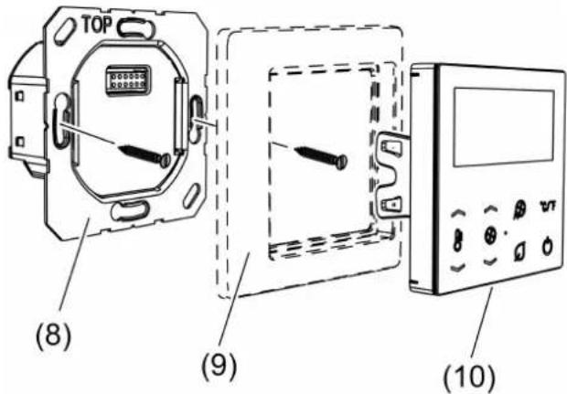
Figure 4: Fitting the device
(8) Power supply unit
(9) Frame
(10) Cover
If the motor of the fan coil unit requires a defined switchover interval between the fan levels, connect a suitable delay module.
■ Connect the fan coil unit for 2-pipe operation to a 2-pipe (Figure 5) or 4-pipe (Figure 6) power supply unit variant.
■ Connect the fan coil unit for 4-pipe operation to a 4-pipe (Figure 7) power supply unit variant.
■ Install the power supply unit (8) in the right orientation in an appliance box. Note marking TOP.
■ Fit the frame (9) onto the insert.
■ Fit the cover (10) onto the insert
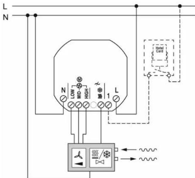
Figure 5: Connection of a 2-pipe fan coil unit with hotel card switch
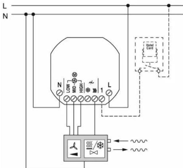
Figure 6: Connection of a 2-pipe fan coil unit to a 4-pipe fan coil controller
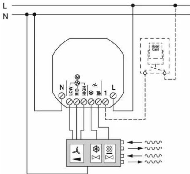
Figure 7: Connection of a 4-pipe fan coil unit with hotel card switch
6.2 Commissioning
First steps – Configuration menu
After mounting the device has to be adapted to the system.
The configuration menu is only available on first commissioning and after resetting to factory settings.
Exception: Project-specific devices are preconfigured in the factory. The settings of the configuration menu are not available for this device.
■ Switch on voltage.
The device displays the software version for 5 seconds. The device subsequently changes into the configuration menu.
■ Set the properties of input 1 for the hotel card switch:
OFF not connected
OPEN for NO contact
CLOSE for NC contact
■ Set the fan coil unit type:
2 Pipes for 2-pipe system
4 Pipes for 4-pipe system
The variants TRD..23028.. are permanently set to 2 Pipes.
■ Set the function:
MODE ☐ HEATING: The device only actuates heating units.
MODE ☐ COOLING: The device only actuates climate control units.
MODE ☐ MANUAL: The device actuates heating and climate control units. The
switchover between heating and cooling mode is carried out manually on the device.
MODE ☐ AUTO: The device actuates heating and climate control units and automatically switches between heating and cooling mode.
The Mode ☐ AUTO setting is only available for the TRD..23048.. variants.
■ Set the properties of the actuators to be controlled:
VALVE OPEN for de-energised open actuators
VALVE CLOSE for de-energised closed actuators
■ Setting the switchover delay between fan levels:
CHANGE-OVER-TIME 0 s ... 10 s for adapting the switchover delay to the fan coil unit
When the settings are saved, the device exits the configuration menu. The system parameters set there can only be changed after resetting to factory settings.
Following the first steps it is convenient to compare the temperature measurement and to set the cycle time if necessary. Both settings can be found on the second menu level.
Set offset for temperature measurement
By setting this parameter differences between the measured temperature value at the installation location and the actual room temperature are offset.
■ Measure the temperature in the room and note down as value T1.
- Read the temperature measured by the device and note down as value T2.
■ Calculate the difference between both values T = T1 - T2 and note it down.
■ Open menu level 2.
■ Open the menu page TEMPERATURE OFFSET.
■ Set the difference value on the device.
7 Information for electrically skilled persons

DANGER!
Mortal danger of electric shock.
Disconnect the device. Cover up live parts.
Mounting and connecting the device
Recommended installation height: 1.50 m.
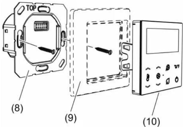
Figure 4: Fitting the device
(8) Power supply unit
(9) Frame
(10) Cover
If the motor of the fan coil unit requires a defined switchover interval between the fan levels, connect a suitable delay module.
■ Connect the fan coil unit for 2-pipe operation to a 2-pipe (Figure 5) or 4-pipe (Figure 6) power supply unit variant.
■ Connect the fan coil unit for 4-pipe operation to a 4-pipe (Figure 7) power supply unit variant.
■ Install the power supply unit (8) in the right orientation in an appliance box. Note marking TOP.
■ Fit the frame (9) onto the insert.
■ Fit the cover (10) onto the insert
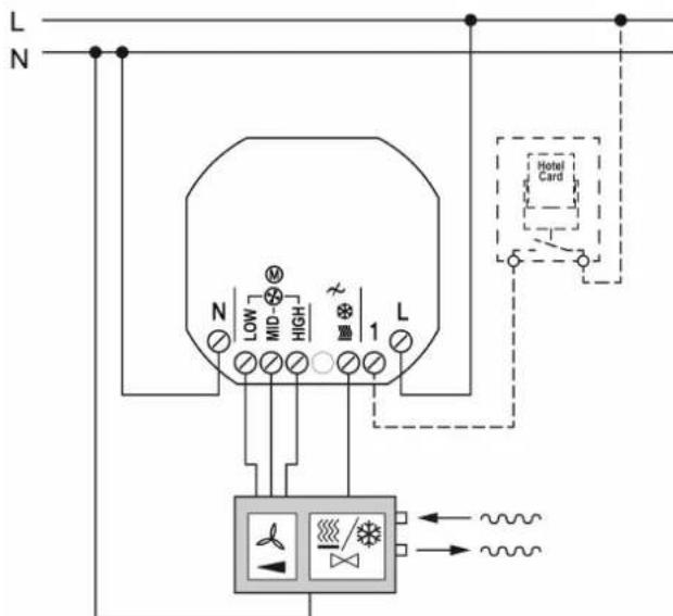
Figure 5: Connection of a 2-pipe fan coil unit with hotel card switch
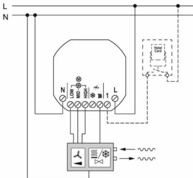
Figure 6: Connection of a 2-pipe fan coil unit to a 4-pipe fan coil controller
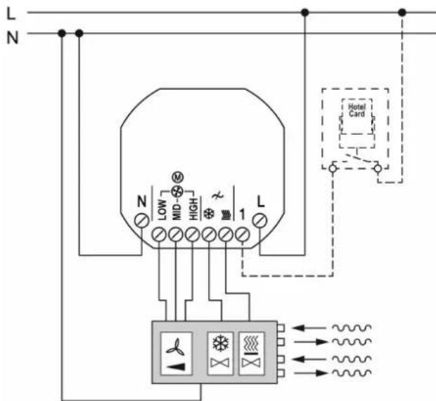
Figure 7: Connection of a 4-pipe fan coil unit with hotel card switch
First steps – Configuration menu
After mounting the device has to be adapted to the system.
The configuration menu is only available on first commissioning and after resetting to factory settings.
Exception: Project-specific devices are preconfigured in the factory. The settings of the configuration menu are not available for this device.
■ Switch on voltage.
The device displays the software version for 5 seconds. The device subsequently changes into the configuration menu.
■ Set the properties of input 1 for the hotel card switch:
OFF not connected OPEN for NO contact CLOSE for NC contact
■ Set the fan coil unit type:
2 Pipes for 2-pipe system 4 Pipes for 4-pipe system
The variants TRD..23028.. are permanently set to 2 Pipes.
■ Set the function:
MODE ☐ HEATING: The device only actuates heating units.
MODE ☐ COOLING: The device only actuates climate control units.
MODE ☐ MANUAL: The device actuates heating and climate control units. The switchover between heating and cooling mode is carried out manually on the device.
MODE ☑ AUTO: The device actuates heating and climate control units and automatically switches between heating and cooling mode.
The Mode ☐ AUTO setting is only available for the TRD..23048.. variants.
■ Set the properties of the actuators to be controlled: VALVE OPEN for de-energised open actuators VALVE CLOSE for de-energised closed actuat
■ Setting the switchover delay between fan levels:
CHANGE-OVER-TIME 0 s ... 10 s for adapting the switchover delay to the fan coil unit
When the settings are saved, the device exits the configuration menu. The system parameters set there can only be changed after resetting to factory settings.
Following the first steps it is convenient to compare the temperature measurement and to set the cycle time if necessary. Both settings can be found on the second menu level.
Set offset for temperature measurement
By setting this parameter differences between the measured temperature value at the installation location and the actual room temperature are offset.
■ Measure the temperature in the room and note down as value T1.
- Read the temperature measured by the device and note down as value T2.
■ Calculate the difference between both values T = T1 - T2 and note it down.
■ Open menu level 2.
■ Open the menu page TEMPERATURE OFFSET.
■ Set the difference value on the device.
8 Appendix
8.1 Technical data
Rated voltage AC 110 ... 230 V \~
Mains frequency 50 / 60 Hz
Total power loss 0.18 ... 0.52 W
Fan output Ⓧ
Output current max. 3 A
Motors 230 V 690 VA
Motors 110 V 300 VA
Switchover delay 0 ... 10 s
Valve outputs ↗
Switching current max. 250 mA
Storage temperature -5 ... +45 °C
Transport temperature -25 ... +70 °C
Ambient temperature -5 ... +45 °C
Relative humidity 5 ... 95 % (no moisture condensation)
Connection
single stranded 1.5 mm ^4
Finely stranded with conductor sleeve 1.5 mm ^4
8.2 Accessories
Key card holder RFID ..CARDRFID..
Energy saving unit ESU230-2
8.3 Warranty
The warranty is provided in accordance with statutory requirements via the specialist trade.
9 Technical data
Rated voltage AC 110 ... 230 V \~
Mains frequency 50 / 60 Hz
Total power loss 0.18 ... 0.52 W
Fan output ⊗
Output current max. 3 A
Motors 230 V 690 VA
Motors 110 V 300 VA
Switchover delay 0 ... 10 s
Valve outputs ↗
Switching current max. 250 mA
Storage temperature -5 ... +45 °C
Transport temperature -25 ... +70 °C
Ambient temperature -5 ... +45 °C
Relative humidity 5 ... 95 % (no moisture condensation)
Connection
single stranded 1.5 mm²
Finely stranded with conductor sleeve 1.5 mm ^4
10 Accessories
Key card holder RFID ..CARDRFID..
Energy saving unit ESU230-2
11 Warranty
The warranty is provided in accordance with statutory requirements via the specialist trade.
ALBRECHT JUNG GMBH & CO. KG
Vollmestraße 1
58579 Schalksmühle
GERMANY
Telefon: +49 2355 806-0
Telefax: +49 2355 806-204
kundencenter@jung.de
www.jung.de
- Safety instructions
- Intended use
- Product characteristics
- Function
- Intended use
- Operation
- Operating elements
- Status LED
- Open menu level 1
- Operation
- Operating modes and display icons
- Operating level and menu levels
- Operating level
- Operating in the menu
- Open menu level 2
- Information for electrically skilled persons
- DANGER!
- Fitting and electrical connection
- Commissioning
- Set offset for temperature measurement
- Information for electrically skilled persons
- First steps – Configuration menu
- Appendix
- Technical data
- Accessories
- Warranty
- Technical data
- Accessories
- Warranty
- ALBRECHT JUNG GMBH & CO. KG
Brand : JUNG
Model : TRDA523028
Category : Temperature regulator