
TS-3000-248B - Uncategorized Mean Well - Free user manual and instructions
Find the device manual for free TS-3000-248B Mean Well in PDF.


| Product Type | DC to AC Power Inverter (Inverter Only) |
| Model | TS-3000-248B |
| Brand | Mean Well |
| Rated Power | 3000W continuous |
| Surge Power | 6000W peak (30 AC cycles) |
| Output Waveform | True sine wave (THD < 3%) |
| Input DC Voltage Range | 42.0 ~ 60.0V (48V nominal) |
| Output AC Voltage | 200 / 220 / 230 / 240V selectable |
| Output Frequency | 50 / 60 Hz ±0.1Hz selectable |
| Efficiency (at full load) | Up to 92% |
| Cooling | Built-in DC fan with ventilation slits |
| Protections | Input reverse polarity, over voltage, under voltage, output overload, short circuit, over temperature |
| Display and Indicators | LED for battery capacity, load level, operating status, alarms |
| Operating Modes | Inverter mode (no built-in charger) |
| Communication Port | Yes, for remote monitoring and optional IRC remote control module |
| Warranty | 3 years global warranty |
| Certifications | FCC Part 15 compliant |
| Installation Clearance | At least 15cm on both sides for airflow |
| Mounting Orientation | Horizontal only |
| AC Outlet Types | Multiple options (Type A, B, C, D, E, F, G) depending on region |
| Recommended Battery Capacity | 48V / 100Ah or higher (lead-acid) |
| No Load Power Consumption | < 1.0mA when power switch is OFF |
Frequently Asked Questions - TS-3000-248B Mean Well
User questions about TS-3000-248B Mean Well
0 question about this device. Answer the ones you know or ask your own.
Ask a new question about this device
Download the instructions for your Uncategorized in PDF format for free! Find your manual TS-3000-248B - Mean Well and take your electronic device back in hand. On this page are published all the documents necessary for the use of your device. TS-3000-248B by Mean Well.
USER MANUAL TS-3000-248B Mean Well
natural_image
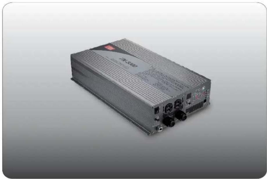
Exterior view of a power supply unit (no visible text or symbols)TN/TS-3000 Inverter Instruction Manual

TN/TS-3000 Inverter Instruction Manual Index
- Safety Guidelines.... 1
- Introduction.... 1
2.1 Features 2
2.2 Main Specification 3
2.3 System Block Diagram.... 3
- User Interface Panel 3
3.1 Front Panel 3
3.2 AC Terminal Configuration 5
3.3 LED Indicator on Front Panel 5
3.4 Functional Indication and Alarm....5
3.5 Rear Panel 6
- Explanation of Operating Logic.... 6
4.1 Explanation of UPS Mode Control Logic....7
4.2 Explanation of Energy Saving Mode Control Logic....9
5.TN/TS-3000 Initial Output Voltage & Frequency and Procedure to Setting Operating Mode....1
5.1 Initial Factory State 1
5.2 Initial Setting for Transition Voltages.... 1
5.3 Procedures to Setting Operating Mode, Output Voltage, Frequency, and Standby Saving Mode.... 1
5.4 Remote Monitoring Software.... 1
5.5 Remote Control Module (Optional Accessory).... 1
- Protection 1
6.1 Input Protection.... 1
6.2 Output Protection.... 1.
- Installation & Wiring 1
- Failure Correction Notes 1
- Warranty 1
June. 2020 Version 11
1. Safety Guidelines (Please read through this manual before assembling the inverter)
- Risk of electrical shock and energy hazard. All failures should be examined by a qualified technician. Please do not remove the case of the inverter by yourself!
- After connecting the AC input of the inverter to the utility, the AC outlet of the inverter will have AC output even if the power switch on the front panel is in the OFF position.
- It is highly recommended to mount the unit horizontally.
- Please do not install the inverter in places with high moisture or near water.
- Please do not install the inverter in places with high ambient temperature, under direct sunlight, or near fire source.
- Please only connect batteries with the same brand and model number in one battery bank. Using batteries from different manufacturers or different capacities is strictly prohibited!
- Never allow a spark or flame in the vicinity of the batteries.
- Make sure the air flow from the fan is not obstructed at both sides (front and back) of the inverter. (Please allow at least 15cm of space)
- Please do not stack any object on the inverter as it may impede heat dissipation.
- Please do not turn on the inverter before start the engine if inverter connect to vehicle's battery directly.
- This device complies with part 15 of the FCC Rules. Operation is subject to the following two conditions:
(a) This device may not cause harmful interference, and
(b) this device must accept any interference received, including interference that may cause undesired operation.

WARNING: Batteries will have aging problem after years of operation. It is suggested to execute regular battery maintenance (e.g. every year). Once aged, the batteries should be changed by professional technician, or the failed batteries may cause fire or other hazards.

Don't disassemble
Keep away from moisture

Keep away from
fire or high
temperature

Don't stack on the inverter

Keep good ventilation
2. Introduction
- The TN/TS-3000 is a true sine wave DC/AC inverter fully digital controlled by an advanced microprocessor. By using the setting button on the front panel or the monitoring software, the user can flexibly adjust output voltage, frequency, turn ON or OFF standby saving mode, and operating mode.
- TN-3000 possesses 2 operating modes, UPS and Energy saving mode. Depending on operating requirement, the user can flexibly reconfigure operating mode to suit their needs. When the UPS mode is selected, AC utility voltage will automatically be bypassed to the output load/equipment. If there is an interruption to the AC
utility voltage, battery inverter will automatically take over power provision like→an UPS system. When the energy saving mode is selected in combination with the use of solar panel, solar power will take priority, thus effectively saving electrical power. Basically, the operating modes can be easily set to match weather conditions or other special needs.
- TN-3000 is equipped with 2 methods of battery charging. An AC charger and solar charger coexist in this unit. The user only needs to connect their own battery banks and solar panel to form an energy saving independent power station which is in line with our goals of conserving energy and being environmental friendly.
- TS-3000 Series only possess the inverter function. It uses batteries as the input source and coverts it into AC power.
• TN/TS-3000 Series can provide 3000W pure sine wave output continuously, 3450W for 3 minutes, and peak power of 6000W for all kinds of loads such as inductive, capacitive, and peak demanding motors. General applications include PC, ITE, yachts, RV, home appliances, motor, power tools, industrial control equipment, AV system, and etc.
(Note: Descriptions which are highlighted represents functions exclusive to the TN-3000 Series)
2.1 Features
- True sine wave output (THD < 3.0%)
• 3000W rated output - Surge power capability up to 6000W
• High efficiency up to 92% - Output voltage/frequency selectable
- Complete protections for both the input and output
- Battery low alarm and indicator
- Complete LED indication for operating status
• Fully digital controlled with digital display - Can be used for most electronic products requiring AC input
- Selectable UPS or Energy saving mode
• → Utility inverter transfer time < 10ms (Typ.)
- Solar charging current 30A max.
- Computer-based monitoring software (optional for TS-3000)
- Optional remote control accessory (IRC Series)
• 3 year global warranty
2.2 Main Specifications
TN/TS-3000
| MODEL | 112 124 148 | 212 224 248 | |||||
| OUTPUT | Rated power | 3000W continuously, 3450W for 3 minutes, 4500W for 10 seconds, 6000W for 30 AC cycles | |||||
| Factory setting | 110V 60Hz | 230V 50Hz | |||||
| Output voltage | 100 / 110 / 115 / 120V (adjustable) | 200 / 220 / 230 / 240V (adjustable) | |||||
| Frequency | 50 / 60Hz 0.1Hz± | ||||||
| WAVEFORM | True sine wave (THD <3.0%) | ||||||
| PROTECTION | AC short Overload Over Temperature, and circuit breaker、 | ||||||
| INPUT | BAT. VOLTAGE | 10.5 ~ 15.0V | 21.0 ~ 30.0V | 42.0 ~ 60.0V | 10.5 ~ 15.0V | 21.0 ~ 30.0V | 42.0 ~ 60.0V |
| DC CURRENT | 300A | 150A | 75A | 300A | 150A | 75A | |
| EFFICIENCY | 88% | 90% | 91% | 89% | 91% | 92% | |
| OFF MODE CURRENT DRAW | Under 1.0mA at power switch OFF | ||||||
| PROTECTION | Over current, battery reverse polarity, battery low alarm, and battery low shutdown | ||||||
| AC CHARGER | |||||||
| CHARGE VOLTAGE | 14.3V | 28.5V | 57V | 14.3V | 28.5V | 57V | |
| CHARGE CURRENT | 25A | 12A | 6A | 25A | 12A | 6A | |
| SOLAR PANEL | |||||||
| OPEN CIRCUIT VOLTAGE | 25V max. | 45V max. | 75V max. | 25V max. | 45V max. | 75V max. | |
| SHORT CIRCUIT CURRENT | 30A max. | ||||||
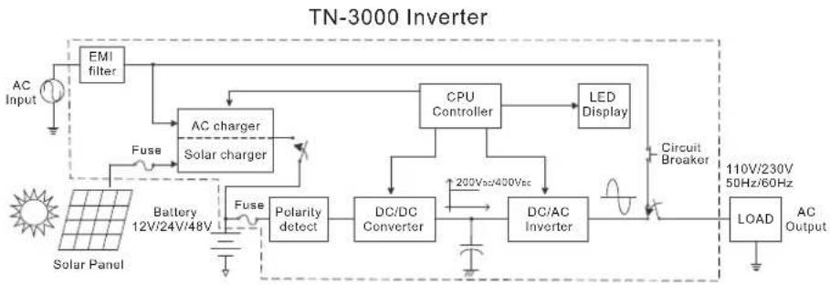
2.3 System Block Diagram
flowchart
graph TD
    A["AC Input"] --> B["EMI filter"]
    B --> C["AC charger Solar charger"]
    C --> D["Fuse"]
    D --> E["Battery 12V/24V/48V"]
    E --> F["Fuse"]
    F --> G["Polarity detect"]
    G --> H["DC/DC Converter"]
    H --> I["200Vsc/400Vsc"]
    I --> J["DC/AC Inverter"]
    J --> K["Circuit Breaker"]
    K --> L["LOAD"]
    L --> M["110V/230V 50Hz/60Hz"]
    M --> N["AC Output"]
    C --> O["CPU Controller"]
    O --> P["LED Display"]
    P --> Q["AC Inverter"]
    Q --> R["DC/AC Inverter"]
Figure 2.1 System block diagram
3.User Interface Panel
3.1 Front Panel
A POWER ON/OFF switch: The inverter will turn OFF if the switch is in the OFF position.
⑧ AC OUTPUT Socket: To satisfy demands of different geographic areas all over the world, there are many optional AC outlets to choose from. (A & B types are standard; C, D, E, F types are optional)
| MODEL NO. 112 124 148 212 224 248 | |||||||
| Socket type |  |  |  |  |  |  |  |
| TYPE-A | TYPE-F | TYPE-G | TYPE-B | TYPE-C | TYPE-D | TYPE-G | |
| Standard | Optional | Optional | Standard | Optional | Optional | Optional | |
| Country | USA | GFCI (60Hz) | ---- | EUROPE | AUSTRALIA | U.K ---- | |
| Certificate | FC | FC | ### | E13CE | E13CE | E13CE | None |
© No fuse breaker with reset button (for AC input): Under "bypass mode", when the AC output is shorted or the load current exceeds the rated current of the No Fuse Breaker, the Breaker will open and that stops bypassing energy for the utility thus prevent possible danger. When the abnormal condition is cleared, the user can press down on the reset button to resume operation.
D No fuse breaker with reset button (for receptacle): The AC output outlet has a current rating of 15A. When the load current exceeds 15A, the Breaker will open and that stops AC provision from the outlet. For application requiring more than 15A, please use the internal terminal block behind the front panel (refer to section 3.2).
⑤ LED indication panel: Operating status, load condition, battery low, and all types of warning will be displayed.
⑤ Function setting: Operating mode, output voltage, frequency, and standby saving mode can be set through this button.
G Communication port: For remote monitoring purpose, the unit can be connected to a PC through this communication port by using the cable and monitoring software. Also for remote control purpose, the unit can be connected to the IRC module through this port.
(H) Ventilation slits: The inverter requires good ventilation for proper operation and prolonging its lifetime.
① Frame ground (FG).
J Grommet hole for input AC utility connection.
K Grommet hole for output AC connection.
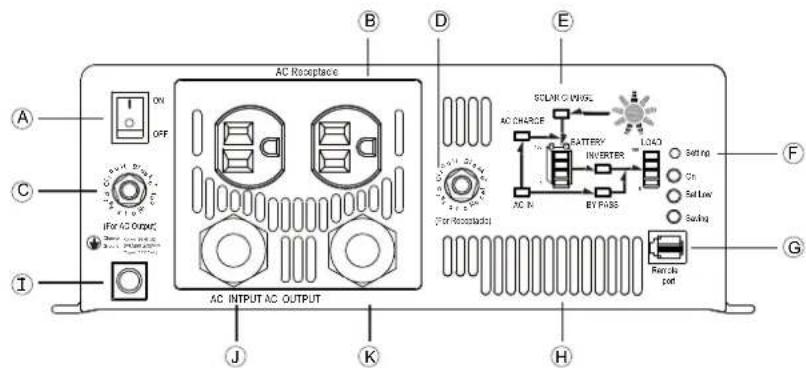
Figure 3.1 Front panel (TN-3000)
3.2 AC Terminal Configuration
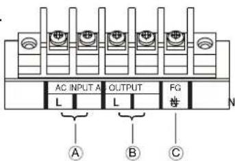
When the load current is >15A, you must use this output terminal connection (terminal can withstand 3000W). To ensure user safety, please follow the wiring instructions as below:
This AC terminal block can be found inside the inverter. To access it, the front panel must first be removed then the output wires can be screwed onto the AC output terminal block. Insert the cable through the AC output grommet, tighten the grommet, and then connect the other end of the cable to the load to complete this connection.
Ⓐ Terminals for AC utility input.
B Terminals for AC output connection.
© Terminal for FG connection.
3.3 LED Indicator On Front Panel
Battery capacity indicator: represents the remaining capacity of external batteries.
| LED Display | LED 1 ON | LED 1~2 ON | LED 1~3 ON | LED 1~4 ON |
| Battery Capacity | 0~25% 26~ | 50% 51~75% 76~100% |
Load condition indicator : represents the magnitude of output loads.
| LED Display | LED 1 ON | LED 1~2 ON | LED 1~3 ON | LED 1~4 ON |
| Battery Capacity | 0~30% 30~ | 50% 50~75% | 75~100% |
3.4 Function Indication and Alarm
© ON indicator: The inverter had started up and the output is normal.
© Bat low indicator: Voltage of external batteries is too low. The inverter will send out a "Beep" sound to warn the users.
Saving mode indicator: The inverter is operating under the "standby saving mode" and there is no AC output.
© AC CHARGE indicator: The built-in AC charger is charging the external batteries.
SOLAR CHARGE indicator: The external solar panels are providing charging current to the external batteries through the built-in solar charger.
©AC IN indicator: The status of utility is normal.
BY PASS indicator: The unit is working under "bypass mode." The AC power consumed by the loads is provided by the utility instead of the inverter.
© INVERTER indicator: The unit is working under "inverter mode." The AC power consumed by the loads is converted from the batteries.
© BATTERY indicator: Display the remaining capacity of external batteries.
◎Display the output load level.LOAD indicator:
3.5 Rear Panel
Ⓐ Battery input (+),(-).
B Solar panel input connector.
© Fan ventilation openings.
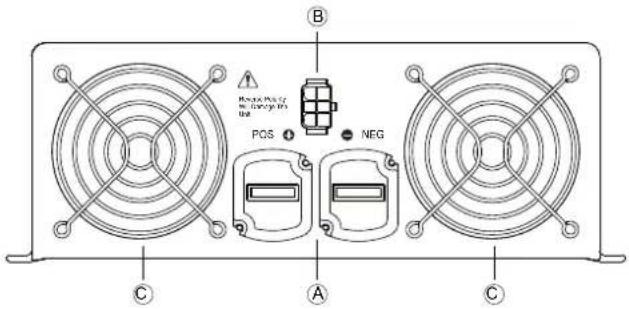
Figure 3.2 Rear panel (TN-3000)
4. Explanation of Operating Logic
TN-3000 is CPU digital controlled true sine wave DC/AC inverter. It is designed to achieve the target of energy conservation and possesses both UPS and energy saving modes. These 2 modes are user adjustable. The unit will be factory set in the UPS mode. Depending on weather and utility conditions, users can manually adjust (refer to section 5.3) or use the monitoring software to switch to the energy saving mode.
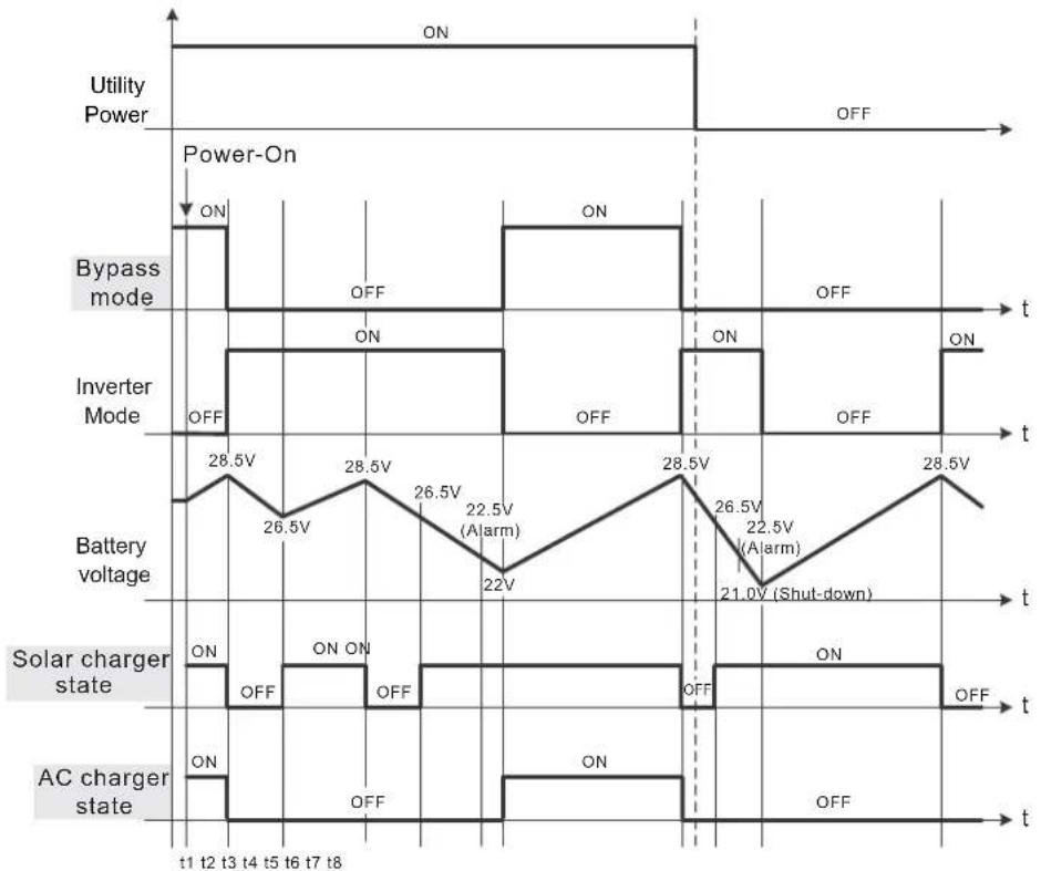
The main difference between the UPS and Energy saving mode is the amount of energy conserved. Under the UPS mode, the unit will remain in the bypass mode as long as utility is available, thus less energy is conserved (refer to figure 4.1 for details of UPS mode control logic). Under the Energy saving mode, the priority of input source chosen is solar panel AC utility battery. If available, the CPU will automatically select external solar panel as its first priority in order to conserve energy. In case of insufficient solar power and utility failure, battery power will be drawn as the last the last resort. When the capacity of batteries drops to around 10 20% , the CPU will remind the end user by continuously sending out warning siren until the system shuts down.
4.1 Explanation of UPS Mode Control Logic
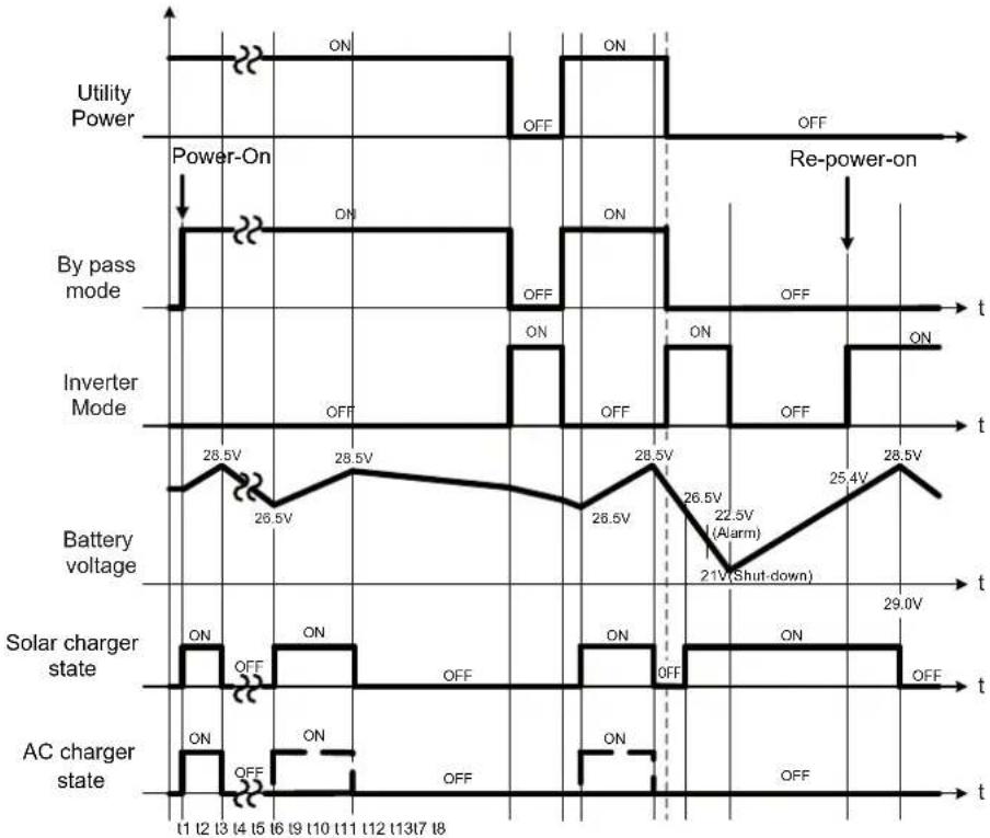
Figure 4.1 Diagram of UPS mode control logic
t1: To ensure the battery is at full capacity, when the TN-3000 is turned ON, the CPU will execute the "bypass mode" automatically connecting the AC main to the load. In the meantime, it will activate both the AC charger and solar charger to simultaneously charge the batteries.
t2: When the batteries are full (battery voltage around 28.5V), both the AC and solar charger will be turned OFF by the CPU to prevent overcharging and reducing battery lifetime.
t3: At this time period, TN-3000 is still in the bypass mode. The battery voltage level will decrease gradually due to standby power dissipation. When the batteries are consumed to around 90% of their capacity (battery voltage around 26.5V) the CPU will restart the charger. The CPU will use solar charging current of 3A as a guideline. When the provided charging current is >3A (solar charge LED indicator turns ON), the solar charger will be used to charge the battery. When the provided solar charging current is under 3A, the AC charger will be turned ON (e.g. night
time or cloudy day) taking over battery charging duty and at this time the solar charger indicator will turn OFF.
t4: With the charger activated, voltage of the battery bank will increase gradually until 28.5V is reached then the CPU will shut off the charger to prevent over charging. At this time, output load is still supplied by utility.
t5 : If utility were to fail at this moment, the CPU will automatically switch (<10ms) to the inverter mode insuring uninterrupted power.
t6 : Once utility recovers, the CPU will switch back to the bypass mode.
t7 : When battery voltage drops to below 26.5V, the CPU will again activate the charger to charge the battery banks (refer to t3 for detailed description).
t8 : Same as t4.
t9 : Due to lack of utility, the CPU will switch to the inverter mode. Since utility is unavailable and it is night time/cloudy, the charging function is in the OFF mode. The AC output relies purely on battery power. So, the battery bank will be depleted rather quickly.
t10 : As the battery discharges below 26.5V and utility remains unavailable and only the solar charger is ON. The battery bank will continue to discharge at a quick pace.
t11 : The battery eventually becomes completely discharged and the inverter shuts down because utility is unavailable. Only when the solar charger current is >3A (day time/sunny) will charging recommence and the battery voltage level will gradually increase.
t12 : Once the battery voltage level has risen to a level capable of restarting the inverter, the inverter will automatically restart. At this time, utility is still OFF, so power to the load is provided by the inverter.
t13 : Utility power is still OFF. If the equipment draws power which is lower than what the solar panel can provide and the solar current is <3A, battery charging will terminate. Inverter will continue to provide power through the battery. The subsequent supply period is subject to capacity of battery and load condition.
Note:
The advantage of the UPS mode is that battery voltage level will be maintained at 90% at all times. This insures that uninterrupted power can be provided to equipment in case of utility failure. Backup period will depend on capacity of battery banks. UPS mode is suitable for areas where AC utility is readily available such as offices and homes.
4.2 Explanation of Energy Saving Mode Control Logic
other
| Signal | Timepoint | Power | |-----------------|---------|-------| | Utility Power | t1 | ON | | Utility Power | t2 | ON | | Utility Power | t3 | ON | | Utility Power | t4 | ON | | Utility Power | t5 | ON | | Utility Power | t6 | ON | | Utility Power | t7 | ON | | Utility Power | t8 | ON | | Power-On | t1 | ON | | Power-On | t2 | ON | | Power-On | t3 | ON | | Power-On | t4 | ON | | Power-On | t5 | ON | | Power-On | t6 | ON | | Power-On | t7 | ON | | Power-On | t8 | ON | | Bypass mode | t1 | ON | | Bypass mode | t2 | ON | | Bypass mode | t3 | ON | | Bypass mode | t4 | ON | | Bypass mode | t5 | ON | | Bypass mode | t6 | ON | | Bypass mode | t7 | ON | | Inverter Mode | t1 | ON | | Inverter Mode | t2 | ON | | Inverter Mode | t3 | ON | | Inverter Mode | t4 | ON | | Inverter Mode | t5 | ON | | Inverter Mode | t6 | ON | | Inverter Mode | t7 | ON | | Battery voltage | t1 | 28.5V | | Battery voltage | t2 | 26.5V | | Battery voltage | t3 | 28.5V | | Battery voltage | t4 | 26.5V | | Battery voltage | t5 | 26.5V | | Battery voltage | t6 | 22.5V (Alarm) | | Battery voltage | t7 | 22V | | Battery voltage | t8 | 28.5V | | Battery voltage | t9 | 26.5V (Alarm) | | Battery voltage | t10 | 22.5V (Alarm) | | Battery voltage | t11 | 21.0V (Shut-down) | | Battery voltage | t12 | 28.5V | | Solar charger state | t1 | ON | | Solar charger state | t2 | OFF | | Solar charger state | t3 | ON | | Solar charger state | t4 | OFF | | Solar charger state | t5 | OFF | | Solar charger state | t6 | OFF | | Solar charger state | t7 | OFF | | Solar charger state | t8 | OFF | | AC charger state | t1 | ON | | AC charger state | t2 | OFF | | AC charger state | t3 | OFF | | AC charger state | t4 | OFF | | AC charger state | t5 | OFF | | AC charger state | t6 | OFF | | AC charger state | t7 | OFF | | AC charger state | t8 | OFF |Figure 4.2 Diagram of energy saving mode control logic
t1: To ensure the battery is at full capacity, when the TN-3000 is turned ON, the CPU will execute the "bypass mode" automatically connecting the AC main to the load. In the meantime, it will activate both the AC charger and solar charger to simultaneously charge the batteries.
t2: When the batteries are full (battery voltage around 28.5V), both the AC and solar charger will be turned OFF by the CPU to prevent overcharging and reducing battery lifetime. The CPU will also switch to inverter mode and the AC electricity provided to the loads will be coming from the batteries.
t3: When the batteries are depleted to around 90% of their capacity (battery voltage around 26.5V), CPU will start up the solar charger but not the AC charger to achieve the goal of energy saving.
t4: If the energy provided by the solar panels is larger than the load requirement, voltage of the battery bank will increase gradually until reaching battery voltage around 28.5V and then the solar charger will shut off to prevent the batteries from overcharging.
t5 : When the capacity of batteries goes down to battery voltage around 26.5V, solar charger will restart and begin charging.
t6 : If the energy provided by the solar panels is lower than consumed by the loads, voltage of the battery bank will decrease gradually to battery voltage around 22.5V. The built-in buzzer will sound to inform the user that battery power is very low.
t7 : If the power consumption of the loads does not decrease and the AC main is normal, the CPU will detect this and the unit will be transferred to "bypass mode." The utility will provide electricity to the loads and charge the battery bank at the same time in order to prevent the unit from shutting off. If the solar current is higher than 3A, the CPU will not activate the AC charger and just let the solar changer charge the batteries to achieve energy saving target.
t8: When there is no AC main, the CPU will shutdown the whole system if the external battery bank voltage is less than 21V in order to prevent over-discharging and reducing its lifetime. After shutdown, the CPU will still provide LED indication so the user knows why the inverter has shut off.
Note:
The advantage of the energy saving mode is that the user only has to add solar panels and solar energy can be harnessed and stored in battery bank for conversion to AC voltage. The user no longer has to rely on AC mains for electricity. The sun can provide all the free electricity needed. Energy saving mode is suitable for areas where AC utility is not readily available such as mountain tops, boats, and vehicles. Even when AC utility is available, the main source of power will still be solar, AC utility will supplement only when necessary. This type of design cuts back the use of paid electricity thus reaching the goal of energy conservation.
5.TN/TS-3000 Initial Output Voltage & Frequency and Procedure to Setting Operating Mode
5.1 Initial Factory State
Initial factory setting is set to 110V / 60Hz or 230V / 50Hz, "UPS mode" and disabled "standby saving mode" are activated. If the users need to revise it for their application, it can be done through the setting button on the front panel to update the CPU setting (please refer to section 5.3 for setting procedures). The unit will start up automatically after the setting procedure is completed and the new settings will be executed. These new settings will be kept even if AC utility, battery, and solar is disconnected. Occurrence of fault conditions leading to inverter shutdown and requiring repower ON will also not affect the new settings.
5.2 Initial Setting for Transition Voltages
TN/TS-3000
| Factory Setting | 112 21 | 12 124 22 | 148 248 | ||
| AC charger transition voltage | 14.3V | 28.5V | 57V | ||
| AC charger start up voltage | 11V | 22V | 44V | ||
| Solar charger start up voltage | 13.3V | 26.5V | 53V | ||
| Solar charger shutdown voltage | 14.3V | 28.5V | 57V | ||
| Inverter shutdown | 10.5V | 21V | 42V | ||
5.3 Procedures to Setting Operating Mode, Output Voltage, Frequency, and Standby Saving Mode
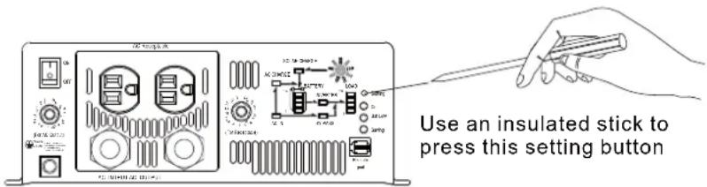
Figure 5.1: Adjustment of output mode, output voltage, frequency, and saving mode
Note TS-3000 does not have steps 3\~4. :
Procedure 1 involves "UPS mode" and "Energy Saving mode" selection, the steps are as follows:
Step 1 The inverter should be turned off while resetting. Input batteries should be connected, AC main can either be connected or disconnected, and the loads should be removed.
Step 2 Use an insulated stick to press down on the setting button and then turn on the power switch. After pressing for 5 seconds, the inverter will send out a "Beep" sound. User can release the button and go on with the setting procedure.
Step 3 Please refer to Table 5.1 and check the LED indication to see if the operating mode is the one you need. If Yes, hold down on the setting button for 3\~5 seconds and the inverter will let out a beep sound signaling that you had skipped to procedure 2 (voltage & frequency setting). However, if change is required please go on to step 4.
(Factory setting: UPS mode)
| Energy saving mode | On | ● |
| Bat Low | ★ | |
| Saving | ★ | |
| UPS mode | On | ○ |
| Bat Low | ★ | |
| Saving | ★ |
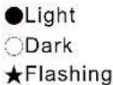
Table 5.1 LED indication for operating mode
Step 4 The LEDs will change state from pressing the setting button for 1 second: and then release. Operating mode can be adjusted as required. After selecting the operating mode, press the setting button for 3\~5 seconds and the inverter will let out a beep sound. Released the button and you will go on to procedure 2 (voltage & frequency setting).
Procedure 2 involves voltage and frequency selection, the steps are as follows:
Step 1 Please refer to Table 5.2 and check whether the combination of output: voltage and frequency is what you need. If Yes, hold down on the setting button for 3\~5 seconds and the inverter will let out a beep sound signaling that you had skipped to procedure 3 (saving mode). However, if change is required please go on to step 2.
(Factory setting: 230VAC/50Hz or 110VAC/60Hz)
| Frequency\Output Voltage | 100Vac 110(200Vac) | Vac 115Vac 120(220Vac) (230Vac) | Vac(240Vac) | ||
| 50Hz | ●On | ● | ● | ● | |
| Bat Low | ○ | ○ | ● | ● | |
| Saving | ○ | ● | ○ | ● | |
| 60Hz | On | ★ | ★ | ★ | ★ |
| Bat Low | ○ | ○ | ● | ● | |
| Saving | ○ | ● | ○ | ● | |
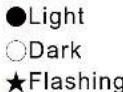
Table 5.2 LED Indication for voltage/frequency combinations
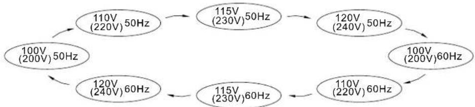
Step 2 The LEDs will change state from pressing the setting button for 1 second: and then release. Please select the combination of output voltage and frequency you need. After making your selection, press the setting button for 3\~5 seconds and the inverter will let out a beep sound. Released the button and you will go on to procedure 3 (saving mode).
flowchart
graph TD
    A["100V (200V) 50Hz"] --> B["110V (220V) 50Hz"]
    B --> C["115V (230V) 50Hz"]
    C --> D["120V (240V) 50Hz"]
    D --> E["100V (200V) 60Hz"]
    E --> F["110V (220V) 60Hz"]
    F --> G["115V (230V) 60Hz"]
    G --> H["120V (240V) 60Hz"]
    H --> I["100V (200V) 50Hz"]
    I --> J["115V (230V) 50Hz"]
    J --> K["120V (240V) 50Hz"]
    K --> L["110V (220V) 60Hz"]
    L --> M["115V (230V) 60Hz"]
    M --> N["120V (240V) 60Hz"]
Figure 5.2 Circulation diagrams of output voltage and frequency
Procedure 3 involves standby saving mode selection, the steps are as follows:
Step 1 : Please refer to Table 5.3 and check whether the "saving mode" is set as required. If yes, hold down on the setting button for 5 seconds and the inverter will let out a beep sound. Released the button and the inverter will automatically store all settings and then restart. However, if change is required please go on to step 2.
(Factory setting: Enable saving mode)
| Saving mode ON | On | ★ |
| Bat Low | ★ | |
| Saving | ● | |
| Saving mode OFF | On | ★ |
| Bat Low | ★ | |
| Saving | ○ |
●Light
○Dark
★Flashing
Table 5.3 LED indication for saving mode ON/OFF
Step 2 The LEDs will change state from pressing the setting button for 1 second: and then release. "Saving mode" can be activated or cancelled according to your need.
5.4 Remote Monitoring Software
Users can make operating mode, voltage / frequency, saving mode, and transition voltage adjustments by using this software. The monitoring software can run on Windows 7 English version, Windows 7 Chinese (Traditional, Taiwan) version, Windows 8 English version, Windows 8 Chinese (Traditional, Taiwan) version, Windows 10 English version and Windows 10 Chinese (Traditional, Taiwan) version from the MW website. Please contact us or our distributor if you have any questions.
5.5 Remote Control Module (Optional Accessory)
(A) User can purchase and use the remote control module to control inverter ON/OFF, turn saving mode ON/OFF, and observe inverter status.
(B)Compatible models:
IRC1 : TS-700 / 1000 / 1500 / 3000 TN-1500 / 3000 ,
(C) Comes with 10FT connection cable (standard) and 25FT/50FT are optional.
6. Protection
6.1 Input Protection
(A) Battery polarity protection: If the battery input is connected in reverse polarity, the internal fuse will blow and the inverter should be send back to us or our authorized distributor for repair.
(B) Battery under voltage protection: When the battery voltage is lower than the pre-set value, the inverter will automatically terminate the output and the "battery low" signal on the display panel will light up. Please refer to table 6.1 for more details about failure signals displayed on the panel.
(C) Battery over voltage protection: When the battery voltage is too high, inverter will automatically terminate the output and the built-in buzzer will sound to inform the user. Please refer to table 6.1 for more details about failure signals displayed on the panel.
! WARNING:
Please choose suitable batteries that is within the input DC voltage range of the inverter (refer to spec).
If the input DC voltage is too low (ex. using 12Vdc battery bank for 24Vdc models), the inverter cannot startup properly.
If the input DC voltage is too high (ex. using 48Vdc battery bank for 24Vdc models), the inverter will get damaged.
(D) Solar charger over current protection: TN-3000 can provide max solar charging current of 30A. If the charging current is too high, the internal fuse will blow and the inverter should be send back to MW for repair.
6.2 Output Protection
(A)Bypass mode: Use no fuse circuit breaker as automatic over current protection.
When over current occurs, the reset button of the circuit breaker on the front panel will pop up and the inverter will shut down. At this time, users should remove the loads, restart the inverter and press down on the reset button of the circuit breaker and the AC output can now be provided normally.
(B) Inverter mode: Under the inverter mode, if any abnormal situation occurs, the display panel will send out failure message (please refer to table 6.1 for failure condition).
(1) OTP: When the internal temperature is higher than the limit value, OTP will activate leading to automatic shutdown. It must be restarted.
(2) Abnormal AC output protection: If the AC output voltage of the inverter is too high or low, the unit will turn OFF and should be restarted again.
(3) AC output short circuit protection: When a short circuit situation occurs at the output or the load increase drastically in a short period of time, the unit will turn OFF and should be restarted again.
(4) Abnormal battery voltage protection: When the battery voltage is too high or low, this protection will be activated. The inverter auto-recovers once the battery goes back to a safe level and the user do not have to restart it.
(5) Output overload protection: When the output is overloaded between 3000W\~3450W, the inverter can continuously provide power for 3 minutes. After that, if the overload condition is not removed, the overload protection will be activated. When the load is higher than 4500W, the overload protection will activate instantly.
Table 6.1 Failure messages on the display panel
| Failure message | LED Indicator | LOAD LOAD (W) [Hz] | Failure message | LED Indicator |
| Output overload (3000W~3450W) |  | AC output short circuit | ||
| Output overload (3450W~4500W) |  | Abnormal battery voltage |  | |
| Output overload (>4500W) |  | Battery aging | [2ASY] | |
| Over temperature | [GSD5] | Fan abnormality | ||
| Abnormal AC output voltage |  | Remote shutdown |
7. Installation & Wiring
(A) Wiring for batteries: Wire connection should be made as short as possible and less than 1.5m is highly recommended. Also make sure suitable wires are chosen based on safety requirement and current rating. Too small cross section will result in lower efficiency, less output power, and the wires may also become overheated and cause danger. Please refer to table 7.1 or consult us or our distributor if you have any questions.
| Rated current of equipment (amp) | Cross section of wire lead ( mm^2 ) | AWGNote | |
| 10A ~ 13A 1.25 | 16 | Choosing suitable wires based on the rating of solar panels and distance from the inverter | |
| 13A ~ 16A | 1.5 | 14 | |
| 16A ~ 25A | 2.5 | 12 | |
| 25A ~ 32A | 4 | 10 | |
| 63A ~ 80A | 16 | 4 | Models using 48V batteries |
| 80A ~ 100A | 25 | 2 | |
| 125A ~ 160A | 50 | 0 | Models using 24V batteries |
| 160A ~ 190A | 70 | 000 | |
| 260A ~ 300A | 150 | 300kcmil | Models using 12V batteries |
| 300A ~ 340A | 185 | 400kcmil |
Table 7.1 Suggestion for wire selection
(B)Suggested battery type and capacity
TN/TS-3000
| Battery type | Lead-acid | |||||
| Battery capacity | 112 212 124 224 148 248 | |||||
| 12V / 400Ah 24V / 200Ah 48V / 100Ah or higher or higher | ||||||
| Input current from solar panel | 30A max. | |||||
(C) Installation requirements:
The unit should be mounted on a flat surface or holding rack with suitable strength. In order to ensure the lifespan of the unit, please refrain from operating the unit in high dust or moisture environment. This is a power unit with built-in DC fan. Please make sure the ventilation openings are not blocked and refrain from continuous operation with heavy load in high ambient environment because this may prevent inverter from operating properly and its life span may be affected. We highly recommend that there should be no objects impeding airflow within 15cm of the ventilation openings.
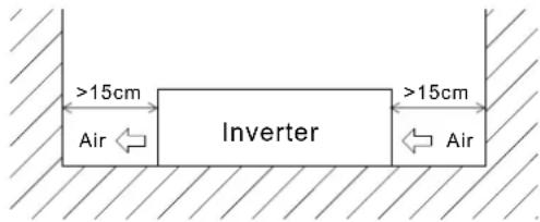
Figure 7.1 Example of installation
(D)Example of system setup
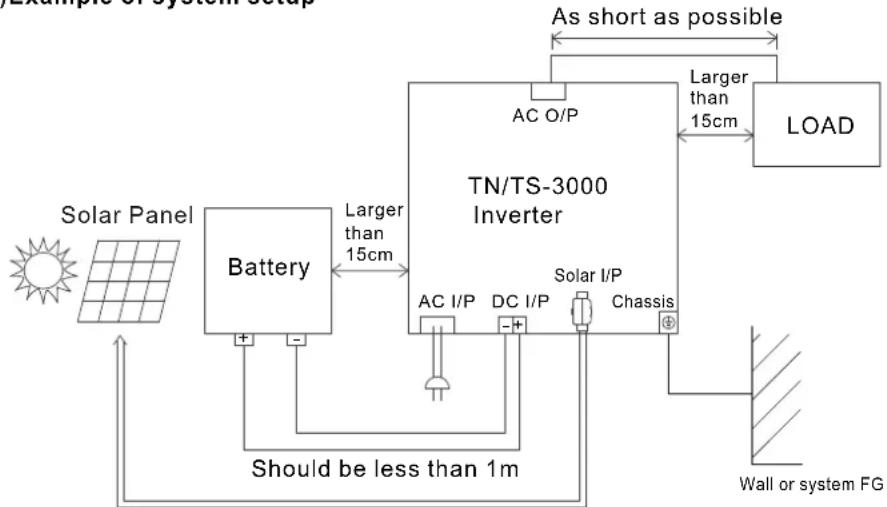
flowchart
graph TD
    A["Solar Panel"] --> B["Battery"]
    B --> C["TN/TS-3000 Inverter"]
    C --> D["AC O/P"]
    C --> E["DC I/P"]
    C --> F["Solar I/P"]
    C --> G["Chassis"]
    H["Wall or system FG"] --> I["Should be less than 1m"]
    I --> B
    J["As short as possible"] --> K["LOAD"]
    L["Larger than 15cm"] --> C
    M["+"] --> B
Depending on the actual length of wiring, choose suitable cross-section of the leads
(E)Derating
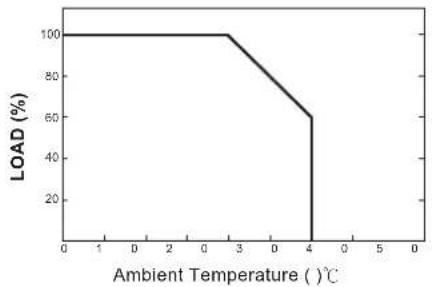
line
| Ambient Temperature (°C) | LOAD (%) | | ------------------------ | -------- | | 0 | 100 | | 3 | 100 | | 4 | 65 |Figure 7.2: Output derating curve
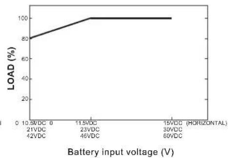
line
| Battery input voltage (V) | LOAD (%) | | ------------------------- | -------- | | 21VDC (42VDC) | 80 | | 11.5VDC (46VDC) | 100 | | 15VDC (HORIZONTAL) | 100 |Figure 7.3 Input derating curve
(F) Notes on output loads:
TN/TS-3000 Series can power most equipment requiring an AC source of 3000W. But for certain type of load, the unit may not work properly.
(1) Since inductive loads or motor based equipments needs a large start up current (6\~10 times of its rated current), please make sure this startup current is less than the maximum current capability of the inverter.
(2) When the loads are capacitive or rectified equipments (such as switching power supply), we suggest operating these equipment at no load or light load during power ON. Increase the load slowly only after the TN/TS-3000 has started up to ensure proper operation.
8. Failure Correction Notes
TN/TS-3000 is a complex product which should be serviced by professional technician. Improper usage or modification may damage the unit or result in shock hazard. If you are not able to clear the failure condition according to the following instructions, please contact us or your closest distributor for repair service.
| Failure status | Possible reasons Recommended | ded solutions |
| No AC output voltage | Abnormal input | Check the AC or DC input sources (solar/battery) to make sure the voltage is within the required range. |
| Over temperature protection | Make sure that the ventilation is not block and the ambient temperature is not too high. Please derate load usage or lower the ambient temperature. | |
| Overload protection | Make sure the output load does not exceed the rated value or the peak startup current is not too high, typically found in inductive or capacitive loads. | |
| Short circuit protection | Make sure the output is not overloaded or short circuited. | |
| Failure status P | Possible reasons Recommended solutions | |
| No voltage at the AC outlet | No fuse circuit breaker has activated | Check whether the load exceeds 15A. |
| No voltage at the AC terminal block | No fuse circuit breaker has activated | Check whether the load has exceeded 20A(212/224/248) or 40A(112/124/148) |
| Discharging period for battery is too short | Battery aged or broken | Replace the batteries. |
| Battery capacity is too small | Reconfirm battery specification and enlarge the battery capacity as suggested. | |
| Malfunction of the charger (no charge voltage) | Please return to us for repair. | |
| Fan does not work | Clog with foreign object | Remove foreign object. |
| Fan malfunction | Please return to us for repair. | |
9.Warranty
Three years of warranty is provided under normal operating conditions.
Please do not change components or modify the unit by yourself or attempt to repair the unit by yourself because Mean Well reserves the right to void the warranty.
明緯企業股份有限公司
MEAN WELL ENTERPRISES CO., LTD.
248 新北市五股區五權三路28號
No.28, Wuquan 3rd Rd., Wugu Dist., NewTaipei City 248, Taiwan
Tel:886-2-2299-6100 Fax:886-2-2299-6200
http://www.meanwell.com E-mail:info@meanwell.com
Your Reliable Power Partner

- TN/TS-3000 Inverter Instruction Manual
- TN/TS-3000 Inverter Instruction Manual Index
- Safety Guidelines (Please read through this manual before assembling the inverter)
- Introduction
- Features
- Main Specifications
- System Block Diagram
- 3.User Interface Panel
- Front Panel
- AC Terminal Configuration
- LED Indicator On Front Panel
- Function Indication and Alarm
- Rear Panel
- Explanation of Operating Logic
- Note:
- 5.TN/TS-3000 Initial Output Voltage & Frequency and Procedure to Setting Operating Mode
- Initial Factory State
- Initial Setting for Transition Voltages
- Procedures to Setting Operating Mode, Output Voltage, Frequency, and Standby Saving Mode
- Procedure 3 involves standby saving mode selection, the steps are as follows:
- Remote Monitoring Software
- Remote Control Module (Optional Accessory)
- Protection
- Input Protection
- ! WARNING:
- Output Protection
- Installation & Wiring
- (B)Suggested battery type and capacity
- Installation requirements:
- Notes on output loads:
- Failure Correction Notes
- 9.Warranty
Brand : Mean Well
Model : TS-3000-248B
Category : Uncategorized