
RCP-1000-24 - Industrial power supply Mean Well - Free user manual and instructions
Find the device manual for free RCP-1000-24 Mean Well in PDF.


| Product Type | Rack-Mounted Power Supply |
| Model | RCP-1000-24 |
| Brand | Mean Well |
| Output Voltage | 24V |
| Output Current | 40A |
| Output Power | 960W |
| Input Voltage Range | 90 ~ 264VAC / 127 ~ 370VDC |
| Input Frequency | 47 ~ 63Hz |
| Efficiency (Typ.) | 87% |
| Dimensions (Rack) | 483.6 x 350.8 x 44 mm (L x W x H) |
| Weight (Packed) | 13.2 kg |
| Cooling | Forced air by built-in DC fan with speed control |
| Protection | Short circuit, overload, over voltage, over temperature |
| Key Features | Active PFC, hot-swap, remote ON/OFF, remote sense, parallel/series operation, I²C (C models) |
| Remote Sense | Up to 0.5V compensation |
| Auxiliary Output | 5V / 0.3A |
| Safety Standards | UL60950-1, TUV EN60950-1, EAC TP TC 004 |
| Warranty | 3 years |
| Operating Temperature | -20~+60°C (with derating) |
| Leakage Current | <1.1mA / 230VAC (single), <3.5mA (rack) |
| Ripple & Noise (max.) | 200mVp-p |
| Current Sharing | Active, up to 3 units per rack, 8 units max in 3 racks |
Frequently Asked Questions - RCP-1000-24 Mean Well
User questions about RCP-1000-24 Mean Well
0 question about this device. Answer the ones you know or ask your own.
Ask a new question about this device
Download the instructions for your Industrial power supply in PDF format for free! Find your manual RCP-1000-24 - Mean Well and take your electronic device back in hand. On this page are published all the documents necessary for the use of your device. RCP-1000-24 by Mean Well.
USER MANUAL RCP-1000-24 Mean Well

natural_image
Two industrial power supply modules with fan and circuit breakers, shown from different angles (no visible text or symbols)RCP-1000 / RCP-1U
Instruction Manual
0. Safety Guidelines ....1
1. Introduction of Series Models....1
1.1 Introduction....1
1.2 Features....1
1.3 Order Information .... 1
1.4 Main Specification ...... 2
2. Mechanical Specification and Input / Output Terminals....3
2.1 Mechanism of Single Unit....3
2.2 Mechanism of Whole Rack System....4
3. Functions ....5
3.1 Input Voltage Range .... 5
3.2 Inrush Current Limiting....5
3.3 Output Power 5
3.4 Power Factor Correction (PFC) 5
3.5 Output Voltage Adjustment....5
3.6 Fan Speed Control 7
3.7 Short Circuit Protection & Over Current Protection 7
3.8 Over Voltage Protection (O.V.P.) 7
3.9 Over Temperature Protection (O.T.P.) 7
3.10 Over Temperature Alarm....7
3.11 AC OK Signal....7
3.12 DC OK Signal 7
3.13 Fan Malfunction Protection 7
3.14 Remote Control 7
3.15 Remote Sense 7
3.16 Hot-Swap Operation 8
3.17 Parallel Operation 8
3.18 Series Operation 9
3.19 Auxiliary Output 9
3.20 Operation of I²C Data Bus (RCP-1000-C models only) 9
4. Notes on Operation 12
4.1 Installation Method ...... 12
4.2 Derating 13
4.3 Warranty 13
0. Safety Guidelines
Risk of electrical shock and energy hazard. All kinds of failure should be examined by the qualified technician. Please do not remove the case of the RCP-1000 or RCP-1U by yourself!
Please do not change any component on the RCP series by yourself or make any kind of modification on it.
©Please do not install the RCP series in places with high moisture or near the water.
Please do not install the RCP series in places with high ambient temperature or under direct contact of sunlight.
©The rated input voltage / frequency are 100\~240VAC and 50/60 Hz. Please don't feed in AC power that over ±10% of the rated value.
Safety protection level of this unit is class I. The grounding wire should be firmly fixed at the "FG" terminal ( ± ) of the rack. The total leakage current of the rack system (including 3 * RCP-1000 units and 1 RCP-1U rack) is less than 3.5mA.
1. Introduction of Series Models
1.1 Introduction
RCP series are rack-mounted power supplies that provide power source for telecom equipments, servers, or monitoring equipments in the 19" racks.
1.2 Features
©44 mm low profile, suitable for standard 1U rack applications.
©Universal AC input / Full range.
Built-in active PFC function, PF>0.96.
©Protections: short circuit / overload / over voltage / over temperature.
Active current sharing up to 3000W (3 units) in one 19" rack; up to 3 racks (8 units maximum) can be connected in parallel.
◎Remote control for single RCP-1000 unit.
Built-in remote sense function.
©Output voltage can be trimmed between 90\~110% rated output voltage.
©Hot-swap operation.
©AC OK and DC OK signal output.
©Forced air cooling by built-in DC fan with fan speed control function.
©5V / 0.3A auxiliary output.
Built-in ORing diode.
©I²C serial data bus (RCP-1000-C models only
©3 years warranty.
1.3 Order Information
1.3.1 Explanation for Encoding


Whole system (3 * RCP-1000 + RCP-1U) :

1.3.2 Marking
Please refer to the safety label on top of each unit before operating (Figure 1-1\~1-3).
©Single unit (RCP-1000):


Figure 1-1: Safety labels of RCP-1000

natural_image
Front view of a server rack unit with four fans (no visible text or labels)

Rack (RCP-1U):


Figure 1-2: Safety labels of RCP-1U□


Whole system (3 * RCP-1000 + RCP-1U):


Figure 1-3: Safety labels of the whole RCP system
1.4 Main Specification
©Single unit
| MODEL | RCP-1000-12 | RCP-1000-24 | RCP-1000-48 | |
| OUTPUT | DC VOLTAGE | 12V | 24V | 48V |
| RATED CURRENT | 60A | 40A | 21A | |
| CURRENT RANGE | 0 ~ 60A | 0 ~ 40A | 0 ~ 21A | |
| RATED POWER | 720W | 960W | 1008W | |
| RIPPLE & NOISE (max.) Note.2 | 150mVp-p | 200mVp-p | 300mVp-p | |
| VOLTAGE ADJ. RANGE(SVR) | 11.6 ~ 12.4V | 23.2 ~ 24.8V | 46.3 ~ 49.7V | |
| VOLTAGE TOLERANCE Note.3 | ±1.0% | ±1.0% | ±1.0% | |
| LINE REGULATION | ±0.5% | ±0.5% | ±0.5% | |
| LOAD REGULATION | ±0.5% | ±0.5% | ±0.5% | |
| SETUP, RISE TIME | 1000ms, 60ms/230VAC at full load | |||
| HOLD UP TIME (Typ.) | 16ms/230VAC at full load | |||
| INPUT | VOLTAGE RANGE Note.4 | 90 ~ 264VAC 127 ~ 370VDC | ||
| FREQUENCY RANGE | 47 ~ 63Hz | |||
| EFFICIENCY (Typ.) | 81% | 87% | 89% | |
| AC CURRENT (Typ.) | 8.5A/115VAC 4.5A/230VAC | 10.5A/115VAC 5.5A/230VAC | 11A/115VAC 5.5A/230VAC | |
| INRUSH CURRENT (Typ.) | COLD START 50A | |||
| LEAKAGE CURRENT | <1.1mA / 230VAC | |||
| PROTECTION | OVERLOAD | 105 ~ 125% rated output power | ||
| Protection type: Constant current limiting, recovers automatically after fault condition is removed | ||||
| OVER VOLTAGE | 13.2 ~ 16.2V | 26.4 ~ 32.4V | 52.8 ~ 64.8V | |
| Protection type: Shut down o/p voltage, re-power on to recover | ||||
| OVER TEMPERATURE | Shut down o/p voltage, recovers automatically after temperature goes down | |||
©Rack system
| MODEL | RCP-3K1U□-12 | RCP-3K1U□-24 | RCP-3K1U□-48 | |
| OUTPUT | RECTIFIER | RCP-1000-12 RCP-1000-24 RCP-1000-48 | ||
| RACK SHELF | RCP-1UI or RCP-1UT | |||
| OUTPUT VOLTAGE | 12V | 24V | 48V | |
| MAX. OUTPUT CURRENT | 180A 63A | 120A | ||
| MAX. OUTPUT POWER Note.5 | 2160W 3024W | 2880W | ||
| INPUT | VOLTAGE RANGE Note.4 | 90~264VAC 127~370VDC | ||
| FREQUENCY RANGE | 47~63Hz | |||
| AC CURRENT (Typ.)PER MODULE | 8.5A/115VAC 4.5A/230VAC | 10.5A/115VAC 5.5A/230VAC | 11A/115VAC 5.5A/230VAC | |
| LEAKAGE CURRENT | <3.5mA / 230VAC | |||
| FUNCTION | AUXILIARY POWER | 5V @ 0.3A | ||
| REMOTE ON-OFF CONTROL | By electrical signal or dry contact ON:short OFF:open | |||
| REMOTE SENSE | Compensate voltage drop on the load wiring up to 0.5V. | |||
| OUTPUT VOLTAGE PROGRAMMABLE | Adjustment of output voltage is allowable to 90~110% of nominal output voltage. Please refer to the Function Manual. | |||
| DC OK SIGNAL | The isolated TTL signal out, Please refer to the Installation Manual | |||
| AC OK SIGNAL | The isolated TTL signal out, Please refer to the Installation Manual | |||
| OVER TEMP WARNING | Logic "High" for over temperature warning, Please refer to the Installation Manual, isolated signal | |||
| ENVIRONMENT | WORKING TEMP. | -20~+60°C (Refer to "Derating Curve") | ||
| WORKING HUMIDITY | 20~90% RH non-condensing | |||
| STORAGE TEMP., HUMIDITY | -40~+85, 10~95% RH non-condensing | |||
| TEMP. COEFFICIENT | ± 0.02%/ (0~50°C) | |||
| VIBRATION | 10~500Hz, 2G 10min./1cycle, 60min. each along X, Y, Z axes | |||
| SAFETY & EMC (Note 6) | SAFETY STANDARDS | UL60950-1, TUV EN60950-1, EAC TP TC 004 approved | ||
| WITHSTAND VOLTAGE | I/P-O/P:3KVAC I/P-FG:2KVAC O/P-FG:0.7KVDC | |||
| ISOLATION RESISTANCE | I/P-O/P, I/P-FG, O/P-FG:100M Ohms / 500VDC / 25°C / 70% RH | |||
| EMC EMISSION | Parameter | Standard | Test Level / Note | |
| Conducted | EN55032 (CISPR32) / EN55011 (CISPR11) | Class B | ||
| Radiated | EN55032 (CISPR32) / EN55011 (CISPR11) | Class B | ||
| Harmonic Current | EN61000-3-2 | ---- | ||
| Voltage Flicker | EN61000-3-3 | ---- | ||
| EMC IMMUNITY | EN55024, EN61204-3, EN61000-6-2 | |||
| Parameter | Standard | Test Level / Note | ||
| ESD | EN61000-4-2 | Level 3, 8KV air; Level 2, 4KV contact | ||
| Radiated | EN61000-4-3 | Level 3 | ||
| EFT / Burst | EN61000-4-4 | Level 3 | ||
| Surge | EN61000-4-5 | Level 4, 4KV/Line-Earth; Level 3, 2KV/Line-Line | ||
| Conducted | EN61000-4-6 | Level 3 | ||
| Magnetic Field | EN61000-4-8 | Level 4 | ||
| Voltage Dips and Interruptions | EN61000-4-11 | >95% dip 0.5 periods, 30% dip 25 periods, >95% interruptions 250 periods | ||
| OTHERS | DIMENSION | Rack 483.6*350.8*44(L*W*H) | ||
| PACKING | 13.2Kg; 1pcs/13.2Kg/2.67CUFT | |||
| NOTE | 1. All parameters NOT specially mentioned are measured at 230VAC input, rated load and 25°C of ambient temperature.2. Ripple & noise are measured at 20MHz of bandwidth by using a 12" twisted pair-wire terminated with a 0.1uf & 47uf parallel capacitor. Under parallel operation of more than one rack connecting together, ripple of the output voltage may be higher than the SPEC at light load condition. It will go back to normal ripple level once the output load is more than 10%.3. Tolerance: includes set up tolerance, line regulation and load regulation.4. Derating may be needed under low input voltages. Please check the derating curve for more details.5. Output of all the RCP-1000 modules are connected in parallel in the rack.6. The power supply is considered a component which will be installed into a final equipment. All the EMC tests are been executed by mounting the unit on a 720mm*360mm metal plate with 1mm of thickness. The final equipment must be re-confirmed that it still meets EMC directives. For guidance on how to perform these EMC tests, please refer to "EMI testing of component power supplies." (as available on http://www.meanwell.com)7. The ambient temperature derating of 3.5°C/1000m with fanless models and of 5°C/1000m with fan models for operating altitude higher than 2000m(6500ft). | |||
2. Mechanical Specification and Input / Output Terminals
2.1 Mechanism of Single Unit

Input / Output Connector Pin. No Assignment(CN501): Postronic PCIB24W9M400A1
| Pin No. | Assignment | Pin No. | Assignment | Pin No. | Assignment | Pin No. | Assignment | Mating Housing |
| 1,2,4 | +V | 10 | AC_OK | 15 | +5V_AUX | 20 | A1 | PostronicPCIB24W9F400A1 |
| 3,5,6 | -V | 11 | DC_OK | 16 | GND_AUX | 21 | A2 | |
| 7 | ON/OFF | 12 | CS | 17 | SDA | 22 | FG | |
| 8 | +S | 13 | V_TRIM | 18 | SCL | 23 | AC/L | |
| 9 | -S | 14 | T_ALARM | 19 | A0 | 24 | AC/N |
2.2 Mechanism of Whole Rack System


Connector Pin No. Assignment(CN500): D-Type Right Angle 25 positions
| Pin No. | Pin | Assign | Pin | Assignment | Assignment | Assign | ||||
| 1 | ON/OFF-A | 6 | +5V-AUX | 11 16 | V-TRIM-B | AC-OK-C | 21 | -S | ||
| 2 | AC-OK-A | 7 | GND-AUX | 12 | T-ALARM-B | 17 | DC-OK-C | 22 | +V | |
| 3 | DC-OK-A | 8 | ON/OFF-B | 13 | NC | 18 | V-TRIM-C | 23 | SCL | |
| 4 | V-TRIM-A | 9 | AC-OK-B | 14 | CS | 19 | T-ALARM-C | 24 | SDA | |
| 5 | T-ALARM-A | 10 | DC-OK-B | 15 | ON/OFF-C | 20 | +S | 25 | -V |
◎Description of CN500 in/out connection pins
| Pin No. | Function | Description |
| 1,8,15 | ON/OFF | Each unit can separately turn the output on and off by electrical or dry contact between ON/OFF A,B,C(pin 1,8,15) and -S(pin 21). Short: ON, Open:OFF. |
| 2,9,16 | AC-OK | High : When the input voltage is >82Vrms +/-4V. Low : when the input voltage in <82Vrms +/-4V. |
| 3,10,17 | DC-OK | High : When the Vout 80%+/-5%. Low : When Vout 80%+/-5% |
| 4,11,18 | V-TRIM | Connection for output voltage trimming. The voltage can be trimmed within its defined range. |
| 5,12,19 | T-ALARM | High : When the internal temperature is within safe limit. Low : 10°C below the thermal shut down limit. |
| 6 | +5V-AUX | Auxiliary voltage output, 4.3~5.3V, referenced to GND-AUX(pin 7). The maximum load current is 0.3A. This output has the built-in "Oring diodes" and is not controlled by the remote ON/OFF control. |
| 7 | GND-AUX | Auxiliary voltage output GND. The signal return is isolated from the output terminals (+V & -V). |
| 14 | CS | Current sharing signal. When units are connected in parallel, the CS pins of the units should be connected to allow current balance between units. |
| 20 | +S | Positive sensing. The +S signal should be connected to the positive terminal of the load. The +S and -S leads should be twisted in pair to minimize noise pick-up effect. The maximum line drop compensation is 0.5V. |
| 21 | -S | Negative sensing. The -S signal should be connected to the negative terminal of the load. The -S and +S leads should be twisted in pair to minimize noise pick-up effect. The maximum line drop compensation is 0.5V. |
| 22 | +V | Positive output voltage. For local sense use only, can't be connected directly to the load. |
| 23 | SCL | Serial clock used on RCP-1000-C models. Refer to the 1C interface description. |
| 24 | SDA | Serial data used on the RCP-1000-C models. Refer to the 1C interface description. |
| 25 | -V | Negative output voltage. For local sense use only, can't be connected directly to the load. |
3. Functions
3.1 Input Voltage Range
©Nominal input voltage range is AC 90\~264V or DC 127\~370V.
To insure proper operation, AC input should be within the pre-specified range. The wrong input will cause the power supply to operate improperly, lose the PFC function or even be damaged.
©Since the RCP Series have built-in active PFC circuit, there will be lower efficiency and output derating is required when operating at lower input voltage (<100VAC).
3.2 Inrush Current Limiting
Built-in inrush current limiting circuit.
The external switch, if needed, should have a current rating exceeding the maximum inrush current.
Since the inrush current limiting circuit mainly consists of thermistor and relay, after turning off the power supply, a 10 second cool down period is recommended before turning it back on. Inrush current will be much higher than the specified value if input thermistor is not allowed sufficient time to cool down.
3.3 Output Power
©Single Unit
RCP-1000-12:720W (12V/60A)
RCP-1000-24 : 960W (24V / 40A)
RCP-1000-48 : 1008W (48V / 21A)
©Whole System
RCP-3K1U□-12:2160W (12V/180A)
RCP-3K1U□-24:2880W (24V/120A)
RCP-3K1U□-48:3024W(48V/63A)
3.4 Power Factor Correction (PFC)
Built-in active power factor correction (PFC) function. Under full load output and the input voltage is within the range of 90\~230Vac, PF>0.96; if the output is less than full load or the input voltage is higher than 230Vac, the PF value will be a little less than 0.96.
3.5 Output Voltage Adjustment
3.5.1 Adjustment of single unit
Output voltage of one RCP-1000 is adjustable through the potentiometer (SVR51, can be found under the small circular hole on top of the unit). Please use a cross-screwdriver with isolated holder to make the adjustment.
3.5.2 Adjustment of single unit or the whole rack system
©Output voltage difference of each unit in the same rack should be maintained within ±1% , or the effectiveness of current sharing might be influenced.
©Output voltage can be adjusted between 90%\~110% of rated value by adding external resistors (R1 and R2). Please refer to Figure 3-1for details.
When the output is tuned to a higher voltage, please notice that the load current should be decreased accordingly. The output wattage of each unit should not exceed its rated value under any circumstances.
3.5.3 Wiring of output voltage adjustment (use voltage trimming function)

Figure 3-1: Voltage trimming by using external resistors
The resistors R1, R2 mentioned in Figure 3-1 should be added independently and the minimum wattage rating is 0.1W. Please refer to 3.5.4\~3.5.6 about the selection of resistance.
3.5.4 Reference resistance value of R1/R2 for RCP-1000-12

line
| R1 (Ω) | Vout (%) | | ------ | -------- | | 180K | 90 | | 240K | 92 | | 350K | 94 | | 560K | 96 | | 1.2M NC| 98 | | >1.2M NC| 100 |
line
| R2 (Ω) | Vout (%) | | ------ | -------- | | NC 300K | 100 | | 120K | 102 | | 62K | 104 | | 31K | 106 | | 13K | 108 | | >13K | 110 |Note: For adjustment under 100% of rated output voltage, R2 should be opened. For adjustment over 100% of rated output voltage, R1 should be opened.
3.5.5 Reference resistance value of R1/R2 for RCP-1000-24

line
| R1 (Ω) | Vout (%) | | ------ | -------- | | 560K | 90 | | 750K | 92 | | 1M | 94 | | 1.6M | 96 | | 3.3M | 98 | | >3M | 100 |
line
| R2 (Ω) | Vout (%) | | ------ | -------- | | NC | 100 | | 330K | 102 | | 130K | 104 | | 62K | 106 | | 30K | 108 | | 10K | 110 |3.5.6 Reference resistance value of R1/R2 for RCP-1000-48

line
| R1 (Ω) | Vout (%) | | ------ | -------- | | 1.3M | 90 | | 1.7M | 92 | | 2.4M | 94 | | 3.6M | 96 | | 7.6M | 98 | | max | 100 |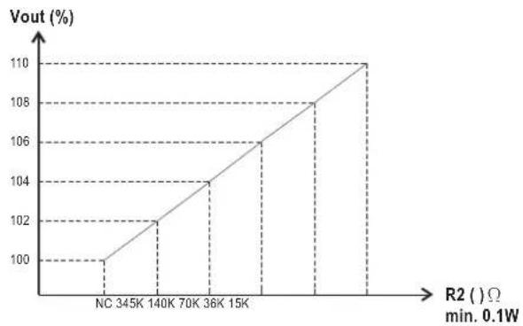
line
| R2 (Ω) | Vout (%) | | ------ | -------- | | NC | 100 | | 345K | 102 | | 140K | 104 | | 70K | 106 | | 36K | 108 | | 15K | 110 |3.6 Fan Speed Control
Built-in fan speed control circuit. The fan speed will be adjusted according to the magnitude of output load.
3.7 Short Circuit Protection & Over Current Protection (O.C.P.)
©Protection comes into effect at short circuit condition or >115% ± 10% of output rated current (constant current limiting mode). The PSU will automatically recover once the short circuit / over current condition is removed.
3.8 Over Voltage Protection (O.V.P.)
Built-in over voltage protection circuit for each RCP-1000 unit.
©The O.V.P. triggering points are different for different output models. Please refer to the specification sheet for details.
©The PSU shuts down when O.V.P. is triggered. To restart the power supply, please switch off AC input first and then wait for 10 seconds before switching it back on.
3.9 Over Temperature Protection (O.T.P.)
Built-in 2 sets of over temperature protection circuit. When the internal temperature exceeds the threshold value, the power supply will shut down automatically (the built-in fan will still operate to cool down the PSU). You should switch off the AC input and remove all possible causes of overheating, and then let the power supply cool down to normal working temperature (needs about 10 minutes\~1hour) before turning it back on.
☐ If the internal temperature is under the threshold value, there will be a "Low" signal (0\~0.5V) between "T-ALARM" and "-V" on CN500; if the internal temperature exceeds the threshold value, there will be a "High" signal (4.5\~5.5V) between "T-ALARM" and "-V" on CN500 connector.
3.10 Over Temperature Alarm
Every RCP-1000 single unit has a detecting circuit to sense its internal temperature. The value of internal temperature can only be read through the I C interface: when the internal temperature of RCP-1000 is higher than 60.8, there will be an alarm signal sent out through the I C interface.
3.11 AC OK Signal
◎Built-in AC input voltage detecting circuit.
When AC input voltage ≥ 82V± 4V , the output voltage can start to work properly and the "AC OK" LED on the front panel will light up (see Figure 3-2). In the mean time, there will be a "Low" signal (0 0.5V) between "AC-OK" and "-V" on CN500 connector.
When AC input voltage ≤ 82V± 4V , the output voltage will be shut down and the "AC OK" LED on the front panel will be turned off. In the mean time, there will be a "High" signal (4.5\~5.5V) between "AC-OK" and "-V" on CN500 connector.
3.12 DC OK Signal
◎Built-in DC output voltage detecting circuit.
When DC output voltage ≥ 80% ± 5% of rated value, the "DC OK" LED on the front panel will light up (see Figure 3-2). In the mean time, there will be a "Low" signal (0\~0.5V) between "DC-OK" and "-V" on CN500 connector.
When DC output voltage ≤ 80%±5% of rated value, the "DC OK" LED on the front panel will be turned off. In the mean time, there will be a "High" signal (4.5\~5.5V) between "DC-OK" and "-V" on CN500 connector.

natural_image
Pure electrical circuit lines without any symbolsFigure 3-2: Front panel of RCP-1000
3.13 Fan Malfunction Protection
Built-in fan malfunction protection circuit. When the DC fan stop operating (fan lock or wire broken), the output will be shut down. Please switch off the AC source and send back to our local distributor or MEAN WELL for repair.
3.14 Remote Control
Built-in remote ON/OFF control circuit. Please refer to Figure 3-3 for single unit or whole rack control.
Notice that the "ON/OFF" and "-S" pin on CN500 should be short connected in order to let the PSU operate properly. If it is open, the output voltage will be shut down.

Whole rack ON/OFF

Single unit ON/OFF
| Between "ON/OFF" and "-S" on CN500 | Output Status |
| SW Open | OFF |
| SW Short | ON |
Figure 3-3: Connection for remote ON/OFF control operation
3.15 Remote Sense
Built-in remote sense circuit that can compensate voltage drop up to 0.5V.
◎When using this function, the sensing wires should either be twisted or shielded to prevent external noise interference. (refer to Figure 3-4)
The voltage drop across the output wires must be limited to less than 0.5V. Also heavy wires with adequate current rating should be used between +V/-V and the load. Please firmly connect the output wires to prevent them from loosing, or the power supply may be out of order.
◎Notice: It is required to use the "Remote Sense" function to let the PSU work properly. If not, the "Local Sense" is still required that "+S" should be shorted to "+V" and "-S" to "-V" as Figure 3-5. Or the output voltage will be too high which may trigger the over voltage protection.

Figure 3-4: Connection for using the "Remote Sense" function

Figure 3-5: Connection for using the "Local Sense" function
3.16 Hot-Swap Operation
Built-in "Oring diode" in every RCP-1000 unit that the single unit can be hot-swapped without turning off the AC source provide to the whole rack system.
Insert the RCP-1000 unit: grasp the handle and push inside the rack through the rail.
◎Pull out the RCP-1000 unit: press the clip shown in Figure 3-6 and pull the unit out.

Figure 3-6: Location of the "clip" on RCP-1000 unit
3.17 Parallel Operation
3.17.1 Operation of single rack
Internal parallel operation in single rack is only suitable for using the same RCP-1000 unit (single unit with the same output voltage and current).
©Each rack (RCP-1U_) have the built-in parallel connection / wiring. Once the RCP-1000 unit insert in the rack then the parallel connection is done.
©Under parallel operation, the connection of other functions can refer to section 3.14 & 3.15.
3.17.2 Operation of three racks in parallel
©Parallel operation is only suitable for the same RCP-1000 unit (single unit with the same output voltage and current) located in up to 3 racks. Totally 8 identical single units operate in parallel is the maximum.
Under parallel operation, the total output current should not exceed 90% of the sum of rated currents. For example: RCP-1000-24x8 connected in parallel (in 3 racks), the maximum output current should be 40A 8 unit 0.9 = 288Ax ×
Adjust the output voltage of all the single units to the value you need and minimize the differences to less than 1% among one another before operating in parallel.
Please paralleling the racks first and then connect to the load (refer to Figure 3.7). Do not connect each rack to the load separately!
©The control signals CS, +S, -S should also be connected in parallel. (refer to Figure 3.7)
©Twisted wires should be used for the wiring of +S and -S. To avoid the interference, the twisted wires should not touch the load wires. (refer to Figure 3.7)

Figure 3.7: Three racks connected in parallel
Under parallel operation of more than one rack connecting together, ripple of the output voltage may be higher than the SPEC at light load condition. It will go back to normal ripple level once the output load is more than 10%.
3.18 Series Operation
◎Higher output voltage can be acquired by connecting different racks in series.
The racks (RCP-1U) connected in series should have the same single unit (RCP-1000-) in each rack. Please refer to Figure 3-8 for the reference connection method.
©Output current for series connection should not exceed the smallest rated current of all series connecting racks.
©The difference in rise times of individual rack will lead to steps/stairs like turn on.
The output voltage after series connection should be less than 60Vdc [the requirement of SELV(Safety Extra Low Voltage) of IEC60950-1].
©It is suggested to add on external diodes shown in Figure 3-8 to prevent the reverse voltage. Rating of these diodes should higher than the total amount of output voltage and current.

Figure 3-8: Operating in series connection
3.19 Auxiliary Output
◎Built-in 5V/0.3A auxiliary output for each rack.
3.20 Operation of I²C Data Bus (RCP-1000-C models only)
©Models with built-in I²C function are available, please refer to the order information in section 1.3.
- Through the I²C interface, users can obtain the operation information of the power supply, including.
- Output voltage, output current, and internal temperature of the power supply.
- Alarm and status information.
- Manufacturing and model information.
3.20.1 Block diagram of I²C data bus and related components

flowchart
graph TD
    A["PCF8574 Register"] -->|A0-A2| B["PCF8591 A/D Converter"]
    A -->|A0-A2| C["AT24C02 EEPROM"]
    B --> D["IC bus"]
    C --> D
    E["AC Input Fail"] --> A
    F["Output Power Good"] --> A
    G["Temperature Waring"] --> A
    H["Over Temperature Protection"] --> A
    I["Fan Fail"] --> A
    J["A0-A2"] --> A
    K["SCA"] --> C
    L["SDL"] --> C
3.20.2 Address of fC bus
Address is set by a 9-pole DIP switch on the rack. There are totally 3 RCP-1000 units in one RCP-1U 2 rack and each RCP-1000 has 3-pole as the addressing switch. (refer to the following diagram)
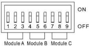
The "ON" position represents logic "0" while the "OFF" position represents logic "1". Switch 1\~3, 4\~6, 7\~9 (low >high bit) can set RCP-1000 unit at position A, B, C in the rack respectively. Please refer to the following table.
| A2 | A1 | A0 | Module |
| 3 | 2 | 1 | A |
| 6 | 5 | 4 | B |
| 9 | 8 | 7 | C |
For example, if we want to set the Module A of RCP-3K1U n -X as the first unit in the I 2 C data bus, Module B as the second, and Module C as the third, then we should set the 9-pole DIP switch on the rack as follow:

3.20.3 Digital status display function (Read Only)
Digital status functions are provided by a PCF8574, 8-bit register. It provides a single 8-bit word when read by the I C controller. "Fault" is indicated by "1" while "Good" level is indicated by "0". The following table specifies the corresponding status for each bit:
| Bit | Good | Fault | Function | Description | |
| 0 | AC Input Fail | 0 | 1 | AC input normal / abnormal | |
| 1 | Output Power Good / Fail | 0 | 1 | Output voltage is less than the SPEC | |
| 2 | Temperature Warning | 0 | 1 | Internal temperature is over 60 , PSU is still on°C | |
| 3 | Over temperature Protection | 0 | 1 | Temperature exceeds normal operating limit, PSU turns off | |
| 4 | Fan Fail Warning | 0 | 1 | Fan fail or stop working | |
| 5 --- | Not Used | --- | --- | ||
| 6 | Not Used | --- | --- | --- | |
| 7 | Not Used --- | --- | --- | ||
PCF8574 slave address:
| Bit | 7 | 6 | 5 | 4 | 3 | 2 | 1 | 0 |
| Value | 0 | 1 | 0 | 0 | A2 | A1 | A0 | R/W |
Read:1 Write:0
3.20.4 Analog status display function (Read Only)
- Analog functions are provided by a single PFC8591, 4-channel 8-bit A/D converter. When this device is read by the serial bus controller, it provides an 8-bit word with the following information:
| A/D Channel | Information |
| 1 | Output voltage |
| 2 | Output Current |
| 3 | Internal Temperature |
| 4 | Not Used |
2.PCF8591 slave address
| Bit | 7 | 6 | 5 | 4 | 3 | 2 | 1 | 0 |
| Value | 1 | 0 | 0 | 1 | A2 | A1 | A0 | R/W |
Read: 1 Write: 0
3.PCF8591 control byte
| Bit | 7 | 6 | 5 | 4 | 3 | 2 | 1 | 0 |
| Value | 0 | 0 | 0 | 0 | 0 | 0 |
0 0 : output voltage
0 1 : output current
1 0 : internal temperature
4.A/D scaling
The following scaling should be employed:
Value (voltage, current, temperature) = Byte Value * Resolution
Please refer to the following table for the scaling of the A/D channels for each model:
| RCP-1000-12 | Range | Resolution | Accuracy |
| Voltage | 0~16V | 0.0625V/bit | ±5% |
| Current | 0~80A | 0.312A/bit | ±10% |
| Temperature | 0~100°C | 0.391°C/bit | ±3°C |
| RCP-1000-24 | Range | Resolution | Accuracy |
| Voltage | 0~33V | 0.129V/bit | +3,-5% |
| Current | 0~55A | 0.215A/bit | ±10% |
| Temperature | 0~100°C | 0.391°C/bit | ±3°C |
| RCP-1000-48 | Range | Resolution | Accuracy |
| Voltage | 0~65V | 0.254V/bit | +2,-5% |
| Current | 0~30A | 0.117A/bit | ±10% |
| Temperature | 0~100°C | 0.391°C/bit | ±3°C |
For example, if the temperature reading value of RCP-1000-24 is "01010010", then convert to decimal value will be "82" 82(value) * 0.391(resolution) = 32.062°C
3.20.5 Function of EEPROM (Read Only)
A 256-byte EEPROM (AT24C02) includes on RCP-1000-C models which stores some information related to the model and manufacturing data. It is programmed at the factory with the data shown below:
| Address Bytes Data | |||
| 4 | 1 | 6 | Manufacturer |
| 20 20 Serial Number | |||
| 40 16 | Revision | ||
| 56 Country of Production | |||
| 72 Model Name | |||
| 88 Output Voltage | |||
| 104 Data of Production | |||
| 254 2 Checksum | |||
The slave EEPROM address:
| Bit 7 | 6 | 5 | 4 | 3 | 2 | 1 | 0 | |
| Value | 1 | 0 | 1 | 0 | A2 | A1 | A0 | R/W |
Read:1 Write:0
4. Notes on Operation
4.1 Installation Method
©The RCP-1U should be mounted in the 19" rack first.
Insert 1\~3 pieces of RCP-1000 (with the same output voltage and current) into the RCP-1U H (refer to Figure 4-1).
◎Definition of module position: A is on the right, B is in the middle, and C is on the left (refer to Figure 4-1).
©This is a power supply with built-in DC fan and please make sure that the ventilation is not blocked. It is suggested that there should be no barriers within 10cm of the ventilating holes.
Connect AC source to the AC input for A, B, C module position respectively depending on the RCP-1000 units assembled into the RCP-1U rack.
Please refer to Table 4-1 about the suggested wire selection for input / output wirings.


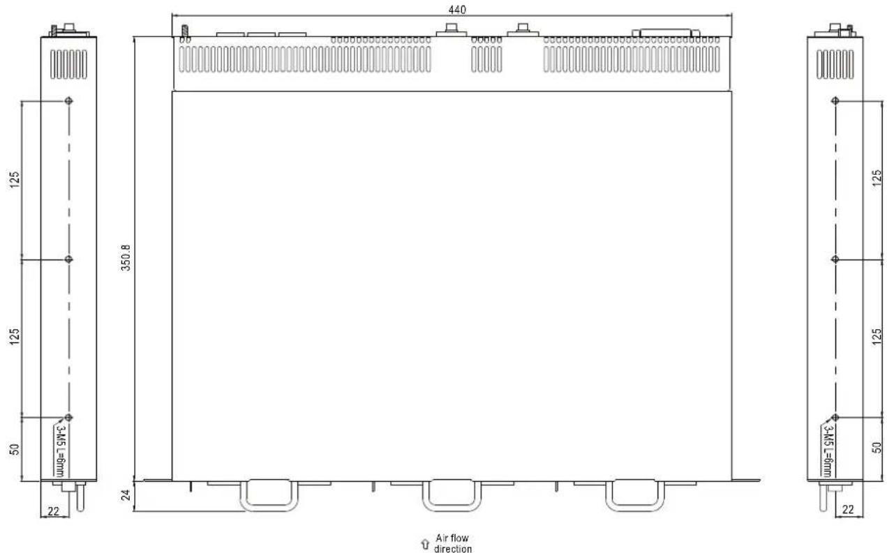

Figure 4-1: System assembly diagram of RCP series
| Input /Output | Module | Current | Minimum Cross-section of Copper Wire | Maximum Current |
| 110VAC | 1 unit | 12Arms | 14AWG UL1015 | 12A |
| 220VAC | 1 unit | 6Arms | 18AWG UL1015 | 6A |
| +12VDC | 1 unit | 60Adc | 8mm2 | 61A |
| 2 unit | 120Adc | 22mm2 | 115A | |
| 3 unit | 180Adc | 38mm2 | 162A | |
| +24VDC | 1 unit | 40Adc | 3.5mm2 | 37A |
| 2 unit | 80Adc | 14mm2 | 88A | |
| 3 unit | 120Adc | 22mm2 | 115A | |
| +48VDC | 1 unit | 21Adc | 2mm2 | 27A |
| 2 unit | 42Adc | 5.5mm2 | 49A | |
| 3 unit | 63Adc | 8mm2 | 61A | |
| Suggested selection for frequent used wirings | 16AWG UL1015 | 8A | ||
| 12AWG UL1015 | 22A | |||
| 10AWG UL1015 | 35A | |||
| 30mm2 | 139A | |||
| 50mm2 | 190A | |||
| 60mm2 | 217A | |||
| 80mm2 | 257A | |||
| 100mm2 | 298A | |||
| 125mm2 | 344A | |||
| 150mm2 | 395A | |||
| 200mm2 | 469A | |||
| 250mm2 | 556A | |||
Table 4-1: Suggested wire selection for input / output wirings
4.2 Derating
◎Output load derating is required for proper operation in high ambient temperature or at low AC input voltage. Please refer to Figure 4-2 for details.

line
| AMBIENT TEMPERATURE (°C) | LOAD (%) | | ----------------------- | -------- | | - | 100 | | 0 | 100 | | 3 | 60 |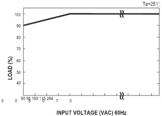
line
| INPUT VOLTAGE (VAC) 60Hz | LOAD (%) | | ------------------------ | -------- | | 90 | 90 | | 95 | 95 | | 100 | 100 | | 115 | 100 | | 264 | 100 | | 7 | 100 | | 0 | 100 | | 1 | 100 | | 2 | 100 | | 3 | 100 | | 4 | 100 | | 5 | 100 |Figure 4-2: Output derating curves for RCP series
4.3 Warranty
Three years of global warranty is provided for RCP series under normal operation. Please do not change any component or modify the unit by yourself or MEAN WELL may reserve the right not to provide the complete warranty service.


- RCP-1000 / RCP-1U
- Instruction Manual
- Safety Guidelines ....1
- Introduction of Series Models....1
- Mechanical Specification and Input / Output Terminals....3
- Functions ....5
- Notes on Operation 12
- Safety Guidelines
- Introduction of Series Models
- Introduction
- Features
- Order Information
- Explanation for Encoding
- Marking
- Main Specification
- Mechanical Specification and Input / Output Terminals
- Functions
- Input Voltage Range
- Inrush Current Limiting
- Output Power
- Power Factor Correction (PFC)
- Output Voltage Adjustment
- Adjustment of single unit
- Adjustment of single unit or the whole rack system
- Wiring of output voltage adjustment (use voltage trimming function)
- Reference resistance value of R1/R2 for RCP-1000-12
- Reference resistance value of R1/R2 for RCP-1000-24
- Reference resistance value of R1/R2 for RCP-1000-48
- Fan Speed Control
- Short Circuit Protection & Over Current Protection (O.C.P.)
- Over Voltage Protection (O.V.P.)
- Over Temperature Protection (O.T.P.)
- Over Temperature Alarm
- AC OK Signal
- DC OK Signal
- Fan Malfunction Protection
- Remote Control
- Remote Sense
- Hot-Swap Operation
- Parallel Operation
- Operation of single rack
- Operation of three racks in parallel
- Series Operation
- Auxiliary Output
- Operation of I²C Data Bus (RCP-1000-C models only)
- Block diagram of I²C data bus and related components
- Address of fC bus
- Digital status display function (Read Only)
- Analog status display function (Read Only)
- 4.A/D scaling
- Function of EEPROM (Read Only)
- Notes on Operation
- Installation Method
- Derating
- Warranty
Brand : Mean Well
Model : RCP-1000-24
Category : Industrial power supply