
ATA8350 - Kit de développement électronique Microchip - Free user manual and instructions
Find the device manual for free ATA8350 Microchip in PDF.


| Product Type | Demo and Evaluation Kit for ATA8350 UWB Transceiver |
| Variants | Variant A (1 Prover node), Variant B (up to 5 Prover nodes) |
| Verifier Node Components | ATSAMC21-XPRO board, ATOLED1 display, ATA8350 Xplained Pro Extension board, UWB antenna with SMA connector, USB cable |
| Prover Node Components (Variant A) | ATSAMC21-XPRO board, ATA8350 Xplained Pro Extension board, UWB antenna with SMA connector, USB cable |
| Prover Node Components (Variant B) | ATAUWB-EK1 board (SAMC21 MCU, ATA8350 UWB module, CAN/LIN driver, DC/DC converter), UWB antenna with SMA connector |
| Number of Prover Nodes | Variant A: 1, Variant B: Up to 5 |
| RF Frequency (Default Channel) | 6.52 GHz |
| RF Frequency Range (Configurable) | 6.52 GHz, 7.04 GHz, 7.56 GHz |
| Bandwidth | >540 MHz |
| Measurement Accuracy (Single Shot) | ±45 cm |
| Measurement Accuracy (Averaged) | ±10 cm (10 measurements) |
| Measurement Modes | Distance-Bounding (single shot), Localization (averaged) |
| Display | ATOLED1 OLED display on Verifier node |
| Supply Voltage (Variant A) | 5V via USB |
| Supply Voltage (Variant B) | 5V via USB or 12V via connector (with DC/DC converter) |
| Software Applications | Demo VRPR, Demo TXRX, Evaluation, Test software packages |
| Programming Tool | Microchip Studio 7 (for SAMC21 MCU) |
| Certification | Not certified for ETSI or FCC; for demonstration/evaluation only |
| Antenna Type | UWB PCB antenna with SMA connector |
| USB COM Port | Yes, for streaming measurement data and terminal applications |
| CAN/LIN Interface | Available on ATAUWB-EK1 board (Variant B) |
| Crystal Trimming | Initial trimming value provided; adjustable via software |
| TX Output Power | Adjustable (0-15 level); default maximum |
Frequently Asked Questions - ATA8350 Microchip
User questions about ATA8350 Microchip
0 question about this device. Answer the ones you know or ask your own.
Ask a new question about this device
Download the instructions for your Kit de développement électronique in PDF format for free! Find your manual ATA8350 - Microchip and take your electronic device back in hand. On this page are published all the documents necessary for the use of your device. ATA8350 by Microchip.
USER MANUAL ATA8350 Microchip
ATA8350 Demo and Evaluation Kit
Introduction
This user's guide describes the use of the ATA8350 Demo and Evaluation kit for the ATA8350 Ultra-Wideband (UWB) transceiver device. This kit includes at least two different UWB nodes, each using a SAM Cortex®-M0 MCU to control the ATA8350 device. The Prover and Verifier nodes are set up as follows:
- Prover node – Must start before the Verifier node, and responds with a telegram once the verifier telegram is received. The measurement cycle finishes when the verifier receives the response telegram or when a timeout occurs.
- Verifier node – Shows the distance measurement data for distance-bounding measurements (single shot measurement) or localization (averaged measurement).
Demo software for distance measurements and data telegram transfer is available for this demo kit. In addition, this kit has an evaluation and a test software package.
The ATA8350 Demo and Evaluation kit comes in two variants:
- Variant A – Comes with one Prover node
- Variant B – Comes with a maximum of five Prover nodes
It also includes software applications for demo, testing and evaluation.
Table of Contents
Introduction....1
- Quick References....3
1.1. Reference Documentation....3
1.2. Reference Packages....3
1.3. Acronyms and Abbreviations....3
- ATA8350 Demo Kit....5
2.1. ATA8350 Demo Kit – Variant A....5
2.2. ATA8350 Demo Kit – Variant B....6
2.3. ATA8350 Demo Kit Components....7
- ATA8350 Demo Kit – Software Application....9
3.1. Demo VRPR Software Application....9
3.2. Demo TXRX Software Application.... 10
3.3. Evaluation Software Application....11
3.4. Test Software Application....12
- Document Revision History....14
The Microchip Website....15
Product Change Notification Service....15
Customer Support....15
Microchip Devices Code Protection Feature....15
Legal Notice....16
Trademarks....16
Quality Management System....17
Worldwide Sales and Service....18
1. Quick References
1.1 Reference Documentation
For further details, refer to the following:
- ATA8350 Impulse-Radio Ultra-Wideband (IR-UWB) Transceiver Data Sheet (DS70005455)
- ATA8350 Impulse-Radio Ultra-Wideband (IR-UWB) Transceiver User's Guide (DS50003127)
• ATA8350 UWB Module Application Note - ATAN0172–ATA5350 Integration into a PEPS System
• ATAN0174-ATA5350 Security Aspects
• ATA8350 Testing and Certification Guide Application Note
1.2 Reference Packages
For additional information, refer to the following software packages:
• ATA8350_VRPR_Demo.zip
• ATA8350_RXTX_Demo.zip
• ATA8350_Evaluation.zip
1.3 Acronyms and Abbreviations
Table 1-1. Acronyms and Abbreviations
| Acronyms Abbreviations | |
| ADC Analog to Digital | |
| ETSI European Telecommunications Standards Institute | |
| FCC Federal Communications Commission | |
| FLL Frequency Lock Loop | |
| MCU Microcontroller Unit | |
| PR Prover | |
| PRo Prover Offset | |
| RF Radio Frequency | |
| RX Receiver | |
| SMA Sub Miniature version A | |
| SSID Secure Session Identifier | |
| SWD Serial Wire Debugger | |
| TX | Transmitter |
| USB Universal Serial Bus | |
| ......continued | |
| Acronyms Abbreviations | |
| UWB Ultra Wide Band | |
| VR Verifier | |
| VRo Verifier Offset | |
| XTAL External Crystal | |
2. ATA8350 Demo Kit
The ATA8350 Demo and Evaluation kit is available in two variants with the same functionality. The only difference is the board used as the Prover node. The following sections explain the differences between 2.1 ATA8350 Demo Kit – Variant A and 2.2 ATA8350 Demo Kit – Variant B.
Note: The Demo kit variants are not certified by the ETSI (Europe) or FCC (USA) regulators. The kits must not be sold in any of these regions and can be operated only for demonstration and evaluation purposes by qualified personnel.
The register settings of the ATA8350 device use the recommended settings as described in the ATA8350 Impulse-Radio Ultra-Wideband (IR-UWB) Transceiver User's Guide and ATA8350 Impulse-Radio Ultra-Wideband (IR-UWB) Transceiver Data Sheet. The demo recommended register settings include an initial crystal trimming value and TX output power set to the maximum value. For the most accurate operation, crystal trimming and TX output power settings must be checked and tuned. For more details, refer to the ATA8350 Impulse-Radio Ultra-Wideband (IR-UWB) Transceiver User's Guide.
2.1 ATA8350 Demo Kit – Variant A
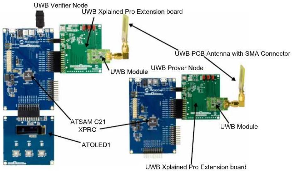
This Demo and Evaluation kit variant uses ATSAMC21-XPRO MCU boards, one for the Verifier node and one for the Prover node to control the operation of the ATA8350 UWB device. The following components are used for the Verifier and Prover nodes:
Verifier Node:
• One ATSAMC21-XPRO board
• One ATOLED1 Xplained Pro Extension board
• One ATA8350 Xplained Pro Extension board with ATA8350 UWB device
• One UWB antenna with SMA connector
- One USB cable for 5V USB supply and for connection to a PC with Microchip Studio 7
Prover Node:
• One ATSAMC21-XPRO board
- One ATA8350 Xplained Pro Extension board with ATA8350 UWB device
• One UWB antenna with SMA connector
- One USB cable for 5V USB supply and for connection to a PC with Microchip Studio 7
Each node is programmed with a demo application for the operation as a verifier in VRo mode or as a prover in PRo mode. For more details, refer to the ATA8350 Impulse-Radio Ultra-Wideband (IR-UWB) Transceiver User's Guide. The applications operate at an RF frequency of 6.52 GHz with more than 540 MHz bandwidth during the distance measurement. The default frequency channel can be changed through the application's software. With the ATA8350 Evaluation package and ATA8350 Testing packages, the frequency channel can be changed to 7.04 and 7.56 GHz based on the user's requirements. For more details, refer to the ATA8350 Impulse-Radio Ultra-Wideband (IR-UWB) Transceiver Data Sheet.
The following figure illustrates the demo setup for the variant A.
Note: All the Demo kits are preprogrammed, and the user can start using the demo application when the boards are powered.
Figure 2-1. Demo Kit – Variant A
2.2 ATA8350 Demo Kit – Variant B
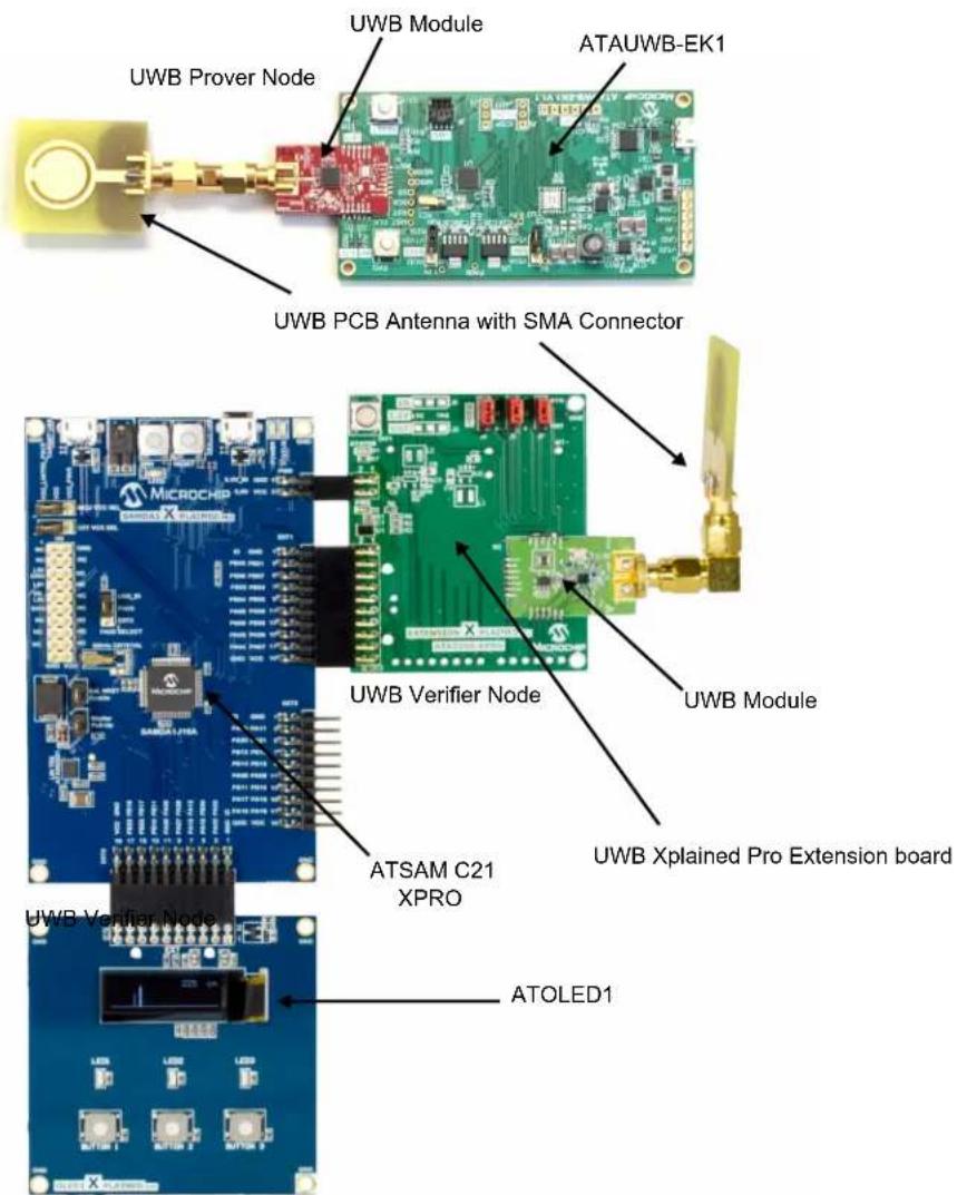
This Demo and Evaluation kit variant uses an ATSAMC21-XPRO board for the Verifier node and up to five ATAUWB-EK1 boards for the Prover node with an embedded SAMC21 MCU board to control the operation of the ATA8350 UWB device. The following components are used for the Verifier and Prover nodes:
Verifier Node:
• One ATSAMC21-XPRO board
• One ATOLED1 Xplained Pro Extension board
• One ATA8350 Xplained Pro Extension board with ATA8350 UWB device
• One UWB antenna with SMA connector
• One USB cable for 5V USB supply and for connection to a PC with Microchip Studio 7
Prover Node:
- Up to 5 ATAUWB-EK1 boards with:
- SAMC21 MCU
- ATA8350 UWB module. For more details, refer to the ATA8350 UWB Module Application Note.
- CAN and LIN driver IC
- 12V supply with DC/DC converter for 5V, 3.3V and 1.25V supply
- USB connector for 5V supply
- MCP2221A USB COM port driver with 5V USB supply
Note: The ATAUWB-EK1 board requires an SWD debugger (Microchip-ICE) for programming and debugging of the software application.
- Up to 5 UWB antenna with SMA connector
Each node is programmed with a demo application for the operation as a verifier in VRo mode or as a prover in PRo mode. For more details, refer to the ATA8350 Impulse-Radio Ultra-Wideband (IR-UWB) Transceiver User's Guide. During the distance measurement, the applications operate at an RF frequency of 6.52 GHz with more than 540 MHz bandwidth. The default frequency range can be changed using the application's software. With the ATA8350 Evaluation package and ATA8350 Testing packages, the other frequency ranges can be used, for example, 7.04 and 7.56 GHz. For more details, refer to the ATA8350 Impulse-Radio Ultra-Wideband (IR-UWB) Transceiver Data Sheet.
The following figure illustrates the demo setup for the variant B. The Prover and Verifier nodes are preprogrammed with the demo application, and start once the USB power is applied.
Note: All the Demo kits are preprogrammed, and the user can start using the demo application when the boards are powered.
Figure 2-2. Demo Kit – Variant B
2.3 ATA8350 Demo Kit Components
The ATAUWB-EK1 board allows an addition to supply the board with 12V instead of 5V from the USB connection. With jumper J8, the 5V supply can be selected from the 12V DC/DC converter or from the 5V USB connector. The connector J1 provides the connections for the CAN and LIN drivers. For the CAN driver, the load resistors R15 and R18 are mounted and must be removed when they are not used as an end node of the CAN network.
The following figure shows details about the connector and buttons of the demo boards. The shutdown button is used to stop the application of the node and to power-down the ATA8350 UWB device. It is recommended the application be shut down before switching off the power supply. The reset button restarts the software application. The following figure explains how to mount the SMA antenna, and how to connect the USB cable.
The Verifier node has an additional jumper J4 to select the distance measurement mode, as described in 3.1 Demo VRPR Software Application.
Figure 2-3. Demo Kit – Details

3. ATA8350 Demo Kit – Software Application
The Demo and Evaluation Kit variant A uses ATSAMC21-XPRO boards with an embedded debugger and a USB COM port. This USB COM port is used in software applications to stream measurement data and for laboratory testing purposes together with a PC terminal application software.
The demo kit variant B uses an ATSAMC21-XPRO board with an embedded debugger and USB COM port and the ATAUWB-EK1 board with SAMC21 MCU and CAN/LIN connectivity. It is supplied either by 12V or by 5V using the USB port. This board is intended for testing in car environments.
The demo software application uses a layer architecture for easy porting between different MCUs. The adaptation to a specific MCU is supported with different Hardware Abstraction Layer (HAL) functions, specific for the MCU and its peripherals. For more details, refer to the Impulse-Radio Ultra-Wideband (IR-UWB) Transceiver User's Guide (DS50003127A).
The ATA8350_VRPR_Demo.zip folder has the following folder structure and files after unpacking:
- Application_Notes\ includes application notes and demo user guide
- Documentation\ includes ATA8350 documentation
- Hardware\ includes documentation for the ATA8350 Xplained Pro Extension board, the ATA8350-EB1 module and the ATAUWB-EK1 module
- Software\ includes application software for: ATA8350 demo for demo kit variant A (Microchip Studio 7 project including source code), ATA8350 demo for demo kit for variant B (Microchip Studio 7 project including source code), ATA8350 test software - ATA8350 evaluation software
Note: To program the SAMC21 devices, Microchip Studio 7 is required; it can be downloaded from www.microchip.com/.
3.1 Demo VRPR Software Application
The demo software application uses a separate software project and implementation for the Verifier node and the Prover node. These two software projects differ only at the application level and use the same driver for the UWB device and MCU peripherals. The verifier software controls the ATOLED1 display, and the UWB device operation initiates the distance measurement and performs the result calculation and display. The prover software initializes the UWB device in the Prover node and responds to the incoming verifier data telegrams. The following figure shows the measurement result on the ATOLED1 for the distance between the nodes in cm, the number of lost data packets since the start of the application and the clock offset between the Verifier node and the Prover node in ppm. The default mode is the VRo and PRo mode at the default channel A, which is 6.52 GHz.
Figure 3-1. ATOLED1 Measurement Data

In addition, a graphical view shows the leading edge position (small bar) and the position of the pulse maximum (larger bar). The position of the two bars gives an indication about the multipath reflections of the RF path between the Verifier and Prover nodes. If both bars are close together, a strong first path is detected (which might be a direct path or a multipath).
The measurement accuracy of ±45 cm is for one single measurement and can be improved by averaging, in other words, when performing measurements at different frequencies or at the same frequency or by evaluating
the le_shift parameter at the Prover and the Verifier node. This is useful in localization applications where a higher accuracy is required. Performing averaging with several measurements improves accuracy but requires more measurement time and power consumption.
The clock offset measurement is required to compensate for clock differences between the Verifier and Prover nodes, which may result in distance errors of up to 300 cm if not compensated.
To evaluate this behavior, the kit may operate in two different distance measurement modes:
- Distance-Bounding mode: The distance measurements are performed as single measurements, in other words, the distance differences up to ±45 cm are observed between each measurement, but with optimal power consumption and measurement time.
- Localization mode: The distance is an average value of 10 measurements, yielding measurement precision within ± 10 cm, but with higher power consumption and measurement time.
After restarting the Verifier node, the selected mode displays on the start-up screen on the ATOLED1. The Prover node is not modified.
The software projects for the demo application are available with the following directory structure:
• Demo Kit – Variant A:
- Demo_Kit/SAMC21-XPRO/UWB_Demo7_VRPR/UWB_Demo7_Verifier.cpro
- Demo_Kit/SAMC21-XPRO/UWB_Demo7_VRPR/UWB_Demo7_Prover1.cpro
- Demo Kit – Variant B:
- Demo_Kit/SAMC21-XPRO/UWB_Demo7_VRPR/UWB_Demo7_Verifier.cproj
- Demo_Kit/ATAUWB-EK1_Prover/UWB_PR_Mode3/UWB_Prover1.cproj
- Demo_Kit/ATAUWB-EK1_Prover/UWB_PR_Mode3/UWB_Prover2.cproj
- Demo_Kit/ATAUWB-EK1_Prover/UWB_PR_Mode3/UWB_Prover3.cproj
- Demo_Kit/ATAUWB-EK1_Prover/UWB_PR_Mode3/UWB_Prover4.cproj
- Demo_Kit/ATAUWB-EK1_Prover/UWB_PR_Mode3/UWB_Prover5.cproj
3.2 Demo TXRX Software Application
The demo software application uses a separate software project and implementation for the Transmitter node and the Receiver node. These two projects differ only at the application level; they use the same driver for the UWB device and MCU peripherals. The transmitter software controls the ATOLED1 display and the UWB device operation and initiates the data transfer and performs the display of the received response. The receiver software initializes the UWB device in the Receiver node and responds to the incoming transmitter data telegrams. The following figure shows the data transfer result on the ATOLED1 for the number of lost packets since the application started and the clock offset between the transmitter node and the receiver node for the last transfer.
Figure 3-2. ATOLED1 Transmitted Data

3.3 Evaluation Software Application
The evaluation software application is available for the ATSAMC21-XPRO boards. This software application uses the USB COM port with a menu (shown in the following figure) to control the application. This requires a typical PC terminal application, which can be connected to the USB COM port using the following settings:
- Baud rate: 115200, 8 data bits, 1 stop bit, no parity, no flow control
Figure 3-3. Evaluation Menu – PC Terminal Application
************************** ATA8350 Evaluation (c)2021 Microchip **************************
Initial trimming of XTAL @ 4.0MHz:
xtrim_freq_val<7:0> = 139
Initial trimming of FLL RX @ 3000MHz:
fllrx_bias min. FLL RX freq.
15 2779MHz
14 2886MHz
13 3024MHz
12 3205MHz
11 3461MHz
10 3846MHz
9 4461MHz
8 7938MHz
FLL RX trim = 13
FLL RX tune = 7
Parameter: RX=6536MHz[892], TX=6536MHz[832], TX_div=3, TX_tune=4, RX_tune=3
Range: RX=5390...7508MHz TX=4221...7040MHz
TX_PA=8(15)dBm, XTAL_TRIM=-31(139)ppm, RNR_SIZE=4byte
Select OP-Mode or Parameter:
0=PR 1=VR 2=PRO 3=VRo 4=RX 5=TX 6=RXo 7=TXo 8=Sniffer
U=PRs V=VRs W=PRso X=VRso Y=Debug R=reset Z=PA-test(TX) Q=PA-test(TXo)
A=TX_RX_freq. B=TXPA_level C=XTAL_trim D=RNR_size
>
The application performs an initial FLL RX trimming to select the trimming value for the FLL RX and TX, and displays the operating parameter for the device. By entering the numeric or alphabetic character, an operating mode or parameter setting can be selected:
• 0: Prover Mode PR
• 1: Verifier Mode VR
• 2: Prover Offset Mode PRo
• 3: Verifier Offset Mode VRo
• 4: Receiver Mode RX
• 5: Transmitter Mode TX
• 6: Receiver Offset Mode RXo
• 7: Transmitter Offset Mode TXo
• 8: Sniffer Mode
• U: Prover Secure Mode PRs
• V: Verifier Secure Mode VRs
• W: Prover Secure Offset Mode PRso
• Y: print debug data from register A20
• X: Verifier Secure Offset Mode VRso
• R: Device Reset
• B: Change TX level between 0 and 15
• C: Change crystal trimming
• Q: TXo Power Test Mode (1 ms RMS mode)
• Z: TX Power Test mode (1 ms RMS mode)
• A: Change RF channel between 6.52, 7.04 and 7.56 GHz
• D: Change data payload size for modes VR, PR, Pro and VRo
This application is typically used with the demo kit variant A on both nodes, with one node selected as a Prover and the other as a Verifier. This requires that this application be run on both nodes, each with a PC terminal application. The user manual is required for the settings and parameter selection.
3.4 Test Software Application
The ATA8350 Test.zip software package includes ATA8350 test software to perform the following tests:
• TX spectrum measurements
• BER measurements
- Crystal calibration
The test software includes two projects:
- UWB PC Test4.cproj to be used with a PC terminal program and a USB PC connection
- UWB_OLED_Test4.cproj to be used with the ATOLED1 extension board and a USB power supply
The following figure shows the test menu when using the test software with a PC terminal application with the following settings:
• 115200 baud rate
- 8 data bits
- 1 stop bit
- No parity
Figure 3-4. Test Menu – PC Terminal Application

Select Test Mode:
0: TX_CHA FO+Fm
1: TX CHA FO-Fm
2: TX_CHA FO+/-Fm
3: TX_CHB FO+/-Fm
4: TX_CHC F0+/-Fm
5: TX CHA PN9
6: RX_CHA PN9
7: TX_CHA PN23
8: RX_CHA PN23
9: XTAL Test
A: TX_CHA VRo mode
B: TX_CHB VRo mode
C: TX_CHC VRo mode
The following tests can be performed with this application (For more details about the test setup, see the ATA8350_Test.zip software package and [7].):
- 0: TX_CHA F0+Fm TX test at the upper modulation frequency of the 6.52 GHz channel
• 1: TX_CHA F0-Fm TX test at the lower modulation frequency of the 6.52 GHz channel
• 2: TX_CHA F0+/-Fm TX test at both modulation frequencies of the 6.52 GHz channel
• 3: TX_CHB F0+/-Fm TX test at both modulation frequencies of the 7.04 GHz channel
• 4: TX_CHC F0+/-Fm TX test at both modulation frequencies of the 7.56 GHz channel - 5: TX_CHA PN9 BER test for the TX operation with the PN9 sequence with the 6.52 GHz channel
- 6: TX_CHA PN23 BER test for the TX operation with the PN23 sequence with the 6.52 GHz channel
- 7: RX_CHA PN9 BER test for the RX operation with the PN9 sequence with the 6.52 GHz channel
• 8: RX_CHA PN23 BER test for the RX operation with the PN23 sequence with the 6.52 GHz channel
• 9: XTAL Test Crystal test to calibrate the crystal frequency
• A: TX_CHA TX test in the VRo mode with 1 ms intervals at the 6.52 GHz channel
• B: TX_CHB TX test in the VRo mode with 1 ms intervals at the 7.04 GHz channel
• C: TX_VRC TX test in the VRo mode with 1 ms intervals at the 7.56 GHz channel
4. Document Revision History
| Revision Date Section Description | ||
| A 06/2021 Document Initial Revision |
The Microchip Website
Microchip provides online support via our website at www.microchip.com/. This website is used to make files and information easily available to customers. Some of the content available includes:
- Product Support – Data sheets and errata, application notes and sample programs, design resources, user's guides and hardware support documents, latest software releases and archived software
- General Technical Support – Frequently Asked Questions (FAQs), technical support requests, online discussion groups, Microchip design partner program member listing
- Business of Microchip – Product selector and ordering guides, latest Microchip press releases, listing of seminars and events, listings of Microchip sales offices, distributors and factory representatives
Product Change Notification Service
Microchip's product change notification service helps keep customers current on Microchip products. Subscribers will receive email notification whenever there are changes, updates, revisions or errata related to a specified product family or development tool of interest.
To register, go to www.microchip.com/pcn and follow the registration instructions.
Customer Support
Users of Microchip products can receive assistance through several channels:
• Distributor or Representative
- Local Sales Office
- Embedded Solutions Engineer (ESE)
- Technical Support
Customers should contact their distributor, representative or ESE for support. Local sales offices are also available to help customers. A listing of sales offices and locations is included in this document.
Technical support is available through the website at: www.microchip.com/support
Microchip Devices Code Protection Feature
Note the following details of the code protection feature on Microchip devices:
- Microchip products meet the specifications contained in their particular Microchip Data Sheet.
- Microchip believes that its family of products is secure when used in the intended manner and under normal conditions.
- There are dishonest and possibly illegal methods being used in attempts to breach the code protection features of the Microchip devices. We believe that these methods require using the Microchip products in a manner outside the operating specifications contained in Microchip's Data Sheets. Attempts to breach these code protection features, most likely, cannot be accomplished without violating Microchip's intellectual property rights.
- Microchip is willing to work with any customer who is concerned about the integrity of its code.
- Neither Microchip nor any other semiconductor manufacturer can guarantee the security of its code. Code protection does not mean that we are guaranteeing the product is “unbreakable.” Code protection is constantly evolving. We at Microchip are committed to continuously improving the code protection features of our products. Attempts to break Microchip’s code protection feature may be a violation of the Digital Millennium Copyright Act. If such acts allow unauthorized access to your software or other copyrighted work, you may have a right to sue for relief under that Act.
Legal Notice
Information contained in this publication is provided for the sole purpose of designing with and using Microchip products. Information regarding device applications and the like is provided only for your convenience and may be superseded by updates. It is your responsibility to ensure that your application meets with your specifications.
THIS INFORMATION IS PROVIDED BY MICROCHIP "AS IS". MICROCHIP MAKES NO REPRESENTATIONS OR WARRANTIES OF ANY KIND WHETHER EXPRESS OR IMPLIED, WRITTEN OR ORAL, STATUTORY OR OTHERWISE, RELATED TO THE INFORMATION INCLUDING BUT NOT LIMITED TO ANY IMPLIED WARRANTIES OF NON-INFRINGEMENT, MERCHANTABILITY, AND FITNESS FOR A PARTICULAR PURPOSE OR WARRANTIES RELATED TO ITS CONDITION, QUALITY, OR PERFORMANCE.
IN NO EVENT WILL MICROCHIP BE LIABLE FOR ANY INDIRECT, SPECIAL, PUNITIVE, INCIDENTAL OR CONSEQUENTIAL LOSS, DAMAGE, COST OR EXPENSE OF ANY KIND WHATSOEVER RELATED TO THE INFORMATION OR ITS USE, HOWEVER CAUSED, EVEN IF MICROCHIP HAS BEEN ADVISED OF THE POSSIBILITY OR THE DAMAGES ARE FORESEEABLE. TO THE FULLEST EXTENT ALLOWED BY LAW, MICROCHIP'S TOTAL LIABILITY ON ALL CLAIMS IN ANY WAY RELATED TO THE INFORMATION OR ITS USE WILL NOT EXCEED THE AMOUNT OF FEES, IF ANY, THAT YOU HAVE PAID DIRECTLY TO MICROCHIP FOR THE INFORMATION. Use of Microchip devices in life support and/or safety applications is entirely at the buyer's risk, and the buyer agrees to defend, indemnify and hold harmless Microchip from any and all damages, claims, suits, or expenses resulting from such use. No licenses are conveyed, implicitly or otherwise, under any Microchip intellectual property rights unless otherwise stated.
Trademarks
The Microchip name and logo, the Microchip logo, Adaptec, AnyRate, AVR, AVR logo, AVR Freaks, BesTime, BitCloud, chipKIT, chipKIT logo, CryptoMemory, CryptoRF, dsPIC, FlashFlex, flexPWR, HELDO, IGLOO, JukeBlox, KeeLoq, Kleer, LANCheck, LinkMD, maXStylus, maXTouch, MediaLB, megaAVR, Microsemi, Microsemi logo, MOST, MOST logo, MPLAB, OptoLyzer, PackeTime, PIC, picoPower, PICSTART, PIC32 logo, PolarFire, Prochip Designer, QTouch, SAM-BA, SenGenuity, SpyNIC, SST, SST Logo, SuperFlash, Symmetricom, SyncServer, Tachyon, TimeSource, tinyAVR, UNI/O, Vectron, and XMEGA are registered trademarks of Microchip Technology Incorporated in the U.S.A. and other countries.
AgileSwitch, APT, ClockWorks, The Embedded Control Solutions Company, EtherSynch, FlashTec, Hyper Speed Control, HyperLight Load, IntelliMOS, Libero, motorBench, mTouch, Powermite 3, Precision Edge, ProASIC, ProASIC Plus, ProASIC Plus logo, Quiet-Wire, SmartFusion, SyncWorld, Temux, TimeCesium, TimeHub, TimePictra, TimeProvider, WinPath, and ZL are registered trademarks of Microchip Technology Incorporated in the U.S.A.
Adjacent Key Suppression, AKS, Analog-for-the-Digital Age, Any Capacitor, AnyIn, AnyOut, Augmented Switching, BlueSky, BodyCom, CodeGuard, CryptoAuthentication, CryptoAutomotive, CryptoCompanion, CryptoController, dsPICDEM, dsPICDEM.net, Dynamic Average Matching, DAM, ECAN, Espresso T1S, EtherGREEN, IdealBridge, In-Circuit Serial Programming, ICSP, INICnet, Intelligent Paralleling, Inter-Chip Connectivity, JitterBlocker, maxCrypto, masView, memBrain, Mindi, MiWi, MPASM, MPF, MPLAB Certified logo, MPLIB, MPLINK, MultiTRAK, NetDetach, Omniscient Code Generation, PICDEM, PICDEM.net, PICkit, PICtail, PowerSmart, PureSilicon, QMatrix, REAL ICE, Ripple Blocker, RTAX, RTG4, SAM-ICE, Serial Quad I/O, simpleMAP, SimpliPHY, SmartBuffer, SMART-I.S., storClad, SQI, SuperSwitcher, SuperSwitcher II, Switchtec, SynchroPHY, Total Endurance, TSHARC, USBCheck, VariSense, VectorBlox, VeriPHY, ViewSpan, WiperLock, XpressConnect, and ZENA are trademarks of Microchip Technology Incorporated in the U.S.A. and other countries.
SQTP is a service mark of Microchip Technology Incorporated in the U.S.A.
The Adaptec logo, Frequency on Demand, Silicon Storage Technology, and Symmcom are registered trademarks of Microchip Technology Inc. in other countries.
GestIC is a registered trademark of Microchip Technology Germany II GmbH & Co. KG, a subsidiary of Microchip Technology Inc., in other countries.
All other trademarks mentioned herein are property of their respective companies.
© 2021, Microchip Technology Incorporated, Printed in the U.S.A., All Rights Reserved.
ISBN: 978-1-5224-8321-2
Quality Management System
For information regarding Microchip's Quality Management Systems, please visit www.microchip.com/quality.
Worldwide Sales and Service
AMERICAS ASIA/PACIFIC ASIA/PACIFIC EUROPE
| Corporate Office | Australia - Sydney | India - Bangalore | Austria - Wels |
| 2355 West Chandler Blvd. | Tel: 61-2-9868-6733 | Tel: 91-80-3090-4444 | Tel: 43-7242-2244-39 |
| Chandler, AZ 85224-6199 | China - Beijing | India - New Delhi | Fax: 43-7242-2244-393 |
| Tel: 480-792-7200 | Tel: 86-10-8569-7000 | Tel: 91-11-4160-8631 | Denmark - Copenhagen |
| Fax: 480-792-7277 | China - Chengdu | India - Pune | Tel: 45-4485-5910 |
| Technical Support: | Tel: 86-28-8665-5511 | Tel: 91-20-4121-0141 | Fax: 45-4485-2829 |
| www.microchip.com/support | China - Chongqing | Japan - Osaka | Finland - Espoo |
| Web Address: | Tel: 86-23-8980-9588 | Tel: 81-6-6152-7160 | Tel: 358-9-4520-820 |
| www.microchip.com | China - Dongguan | Japan - Tokyo | France - Paris |
| Atlanta | Tel: 86-769-8702-9880 | Tel: 81-3-6880-3770 | Tel: 33-1-69-53-63-20 |
| Duluth, GA | China - Guangzhou | Korea - Daegu | Fax: 33-1-69-30-90-79 |
| Tel: 678-957-9614 | Tel: 86-20-8755-8029 | Tel: 82-53-744-4301 | Germany - Garching |
| Fax: 678-957-1455 | China - Hangzhou | Korea - Seoul | Tel: 49-8931-9700 |
| Austin, TX | Tel: 86-571-8792-8115 | Tel: 82-2-554-7200 | Germany - Haan |
| Tel: 512-257-3370 | China - Hong Kong SAR | Malaysia - Kuala Lumpur | Tel: 49-2129-3766400 |
| Boston | Tel: 852-2943-5100 | Tel: 60-3-7651-7906 | Germany - Heilbronn |
| Westborough, MA | China - Nanjing | Malaysia - Penang | Tel: 49-7131-72400 |
| Tel: 774-760-0087 | Tel: 86-25-8473-2460 | Tel: 60-4-227-8870 | Germany - Karlsruhe |
| Fax: 774-760-0088 | China - Qingdao | Philippines - Manila | Tel: 49-721-625370 |
| Chicago | Tel: 86-532-8502-7355 | Tel: 63-2-634-9065 | Germany - Munich |
| Itasca, IL | China - Shanghai | Singapore | Tel: 49-89-627-144-0 |
| Tel: 630-285-0071 | Tel: 86-21-3326-8000 | Tel: 65-6334-8870 | Fax: 49-89-627-144-44 |
| Fax: 630-285-0075 | China - Shenyang | Taiwan - Hsin Chu | Germany - Rosenheim |
| Dallas | Tel: 86-24-2334-2829 | Tel: 886-3-577-8366 | Tel: 49-8031-354-560 |
| Addison, TX | China - Shenzhen | Taiwan - Kaohsiung | Israel - Ra'anana |
| Tel: 972-818-7423 | Tel: 86-755-8864-2200 | Tel: 886-7-213-7830 | Tel: 972-9-744-7705 |
| Fax: 972-818-2924 | China - Suzhou | Taiwan - Taipei | Italy - Milan |
| Detroit | Tel: 86-186-6233-1526 | Tel: 886-2-2508-8600 | Tel: 39-0331-742611 |
| Novi, MI | China - Wuhan | Thailand - Bangkok | Fax: 39-0331-466781 |
| Tel: 248-848-4000 | Tel: 86-27-5980-5300 | Tel: 66-2-694-1351 | Italy - Padova |
| Houston, TX | China - Xian | Vietnam - Ho Chi Minh | Tel: 39-049-7625286 |
| Tel: 281-894-5983 | Tel: 86-29-8833-7252 | Tel: 84-28-5448-2100 | Netherlands - Drunen |
| Indianapolis | China - Xiamen | Tel: 31-416-690399 | |
| Noblesville, IN | Tel: 86-592-2388138 | Fax: 31-416-690340 | |
| Tel: 317-773-8323 | China - Zhuhai | Norway - Trondheim | |
| Fax: 317-773-5453 | Tel: 86-756-3210040 | Tel: 47-72884388 | |
| Tel: 317-536-2380 | Poland - Warsaw | ||
| Los Angeles | Tel: 48-22-3325737 | ||
| Mission Viejo, CA | Romania - Bucharest | ||
| Tel: 949-462-9523 | Tel: 40-21-407-87-50 | ||
| Fax: 949-462-9608 | Spain - Madrid | ||
| Tel: 951-273-7800 | Tel: 34-91-708-08-90 | ||
| Raleigh, NC | Fax: 34-91-708-08-91 | ||
| Tel: 919-844-7510 | Sweden - Gothenberg | ||
| New York, NY | Tel: 46-31-704-60-40 | ||
| Tel: 631-435-6000 | Sweden - Stockholm | ||
| San Jose, CA | Tel: 46-8-5090-4654 | ||
| Tel: 408-735-9110 | UK - Wokingham | ||
| Tel: 408-436-4270 | Tel: 44-118-921-5800 | ||
| Canada - Toronto | Fax: 44-118-921-5820 | ||
| Tel: 905-695-1980 | |||
| Fax: 905-695-2078 |



- ATA8350 DEMO AND EVALUATION KIT
- INTRODUCTION
- TABLE OF CONTENTS
- QUICK REFERENCES
- 1.1 REFERENCE DOCUMENTATION
- 1.2 REFERENCE PACKAGES
- 1.3 ACRONYMS AND ABBREVIATIONS
- ATA8350 DEMO KIT
- 2.1 ATA8350 DEMO KIT – VARIANT A
- VERIFIER NODE
- PROVER NODE
- 2.2 ATA8350 DEMO KIT – VARIANT B
- 2.3 ATA8350 DEMO KIT COMPONENTS
- ATA8350 DEMO KIT – SOFTWARE APPLICATION
- 3.1 DEMO VRPR SOFTWARE APPLICATION
- 3.2 DEMO TXRX SOFTWARE APPLICATION
- 3.3 EVALUATION SOFTWARE APPLICATION
- 3.4 TEST SOFTWARE APPLICATION
- DOCUMENT REVISION HISTORY
- THE MICROCHIP WEBSITE
- PRODUCT CHANGE NOTIFICATION SERVICE
- CUSTOMER SUPPORT
- MICROCHIP DEVICES CODE PROTECTION FEATURE
- LEGAL NOTICE
- TRADEMARKS
- QUALITY MANAGEMENT SYSTEM
- WORLDWIDE SALES AND SERVICE
Brand : Microchip
Model : ATA8350
Category : Kit de développement électronique