
LS50C - Pregnant KEF - Free user manual and instructions
Find the device manual for free LS50C KEF in PDF.


| Product Type | Center Channel Speaker |
| Brand | KEF |
| Model | LS50C |
| Driver Configuration | 1 x 5.25” Uni-Q Driver (Aluminum Cone) + 1 x 1” Vented Aluminum Dome Tweeter |
| Frequency Response | 79 Hz – 28 kHz (±3 dB) |
| Crossover Frequency | 2.5 kHz |
| Sensitivity | 85 dB (2.83V/1m) |
| Impedance | 8 Ohms |
| Recommended Amplifier Power | 25 – 100 Watts |
| Dimensions (H x W x D) | 170 x 376 x 277 mm (6.7 x 14.8 x 10.9 in) |
| Weight | 7.0 kg (15.4 lbs) |
| Enclosure Type | Bass Reflex (Rear Ported) |
| Magnetic Shielding | No (Not required for modern use) |
| Input Terminals | Single-wire binding posts |
| Recommended Placement | Horizontal center channel on or below TV |
| Care Instructions | Wipe with a soft dry cloth. Do not use solvents or abrasive cleaners. |
| Safety Precautions | Do not expose to moisture or extreme temperatures. Keep away from children and pets. |
| Spare Parts Availability | Contact KEF authorized service centers for replacement drivers or crossovers. |
| Repairability | Repairs should be carried out by qualified personnel. User-replaceable parts: grille, feet, screws. |
| Warranty | Typically 2 years (check local regulations) |
| Country of Origin | China (assembly) |
Frequently Asked Questions - LS50C KEF
User questions about LS50C KEF
0 question about this device. Answer the ones you know or ask your own.
Ask a new question about this device
Download the instructions for your Pregnant in PDF format for free! Find your manual LS50C - KEF and take your electronic device back in hand. On this page are published all the documents necessary for the use of your device. LS50C by KEF.
USER MANUAL LS50C KEF
Coupling the Absorber to the Tweeter Dome
Tangerine Waveguide
Tweeter Gap Damper
Motor Design
Bass/Midrange
Motor Design
Crossover
Industrial Design
Specification - LS50 Meta
Appendix 1 - Cabinet
Diffraction
Rigid Bracing/Constrained Layer Damping
Appendix 2 - Ports
Resonances inside the cabinet
Organ pipe resonances
Turbulence
Appendix 3 - Uni-Q
Tweeter
Diaphragm
Tangerine Waveguide
Bass/Midrange driver
Diaphragm
Z-flex Surround
Summary
References
CONTENTS CONT'D
LS50 Wireless II
Overview
Inputs
Connection between Primary and Secondary
Streaming support
DSP Processing
EQ Settings
Desk & Wall Modes
Treble Trim
Phase correction
Bass Extension
Adding a Subwoofer
Syncing with Vision
Firmware
Power Amplification
Summary
Specification - LS50 Wireless II
natural_image
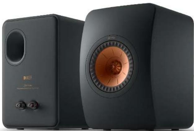
Exterior view of two black KEF audio speakers with visible sound waves (no text or symbols on the devices themselves)Figure 1
1530Mole-Carbon Black
Introduction
"If I have seen further, it is because I stand on the shoulders of Giants."
This famous quotation, attributed to Sir Isaac Newton, illustrates how progress is made in virtually all scientific disciplines - progress is evolutionary, rather than revolutionary. So it is in the development of speakers and techniques developed for one model are carried through to subsequent designs and added to.
That small loudspeakers could be serious hi-fi reproducers was proved in the 1960s with Laurie Fincham's Maxim design for Goodmans. Grossly inefficient, with a cone tweeter and rudimentary crossover, this speaker was outdated by the 1970s, but nevertheless inspired the BBC to design the larger, but still diminutive LS3/5. Originally designed for 14 scale auditorium acoustic modelling, this design was soon recognised for its suitability as a monitor in the cramped surroundings of BBC Outside Broadcast vans. The design was subtly changed to become the legendary LS3/5A when the KEF drive units, with which the speaker was equipped, were modified.
As time went by and loudspeaker design progressed, it was again time to review the capabilities of the LS3/5A and in 2012, to mark the 50th anniversary of KEF, the original LS50 was born. As the name suggests the LS50 Mcla is a development of the original LS50, and again redefines what a small monitor loudspeaker can do.
Philosophy
"Of all art, music is the most indefinable and the most expressive, the most insubstantial and the most immediate, the most transitory and the most imperishable. Transformed to a dance of electrons along a wire, its ghost lives on. When KEF returns music to its rightful habituation, your ears and mind, they aim to do so in the most natural way they can... without drama, without exaggeration, without artifice."
Raymond Cooke, KEF founder
These words set the company's philosophy from day one and they are as relevant today as they have ever been. Continuing research into materials and engineering has always driven KEF's quest for innovation, with the added element of ensuring that the resulting designs work within a typical domestic environment. Everybody deserves great sound.
LS50 Meta
Both LS50 Meta and LS50 Wireless II feature a 12th Generation Uni-Q driver array featuring an industry-first - Metamaterial Absorption Technology (MAT).
This particular Uni-Q driver, whilst being inspired by that of the R Series, has been engineered with regards to the overall system design.
Firstly, the addition of MAT has necessitated considerable redesign of the driver structure, allowing KEF engineers to further refine technologies such as the tweeter gap damper.
Secondly, where R Series features 3-way designs. LS50 Mcla is a 2-way loudspeaker, meaning the midrange driver must cover a much wider bandwidth down into bass frequencies. Whilst excellent for integration, this does provide challenges in regards to performance. With this in mind, KEF engineers made a number of changes to the motor system, suspension, surround and cone of the midrange driver to deliver as smooth a performance as possible.
Tweeter
With any drive unit, as much sound is generated at the rear of the unit as at the front (see figure 2) and this radiation is unwanted and needs to be absorbed.
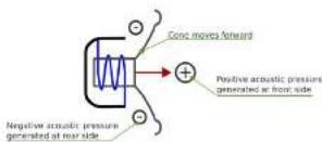
Figure 2 - Generic driver
The most important innovation in this loudspeaker is the near-perfect absorption of the unwanted rear sound generated by the tweeter dome. One might legitimately ask, "Why is this important?"
It's true that, if the tweeter is listened to on its own without the contribution of the bass/midrange driver - and here we are talking of frequencies above about 3kHz - very little seems to come out of it. More revealing is to listen to any loudspeaker system without the tweeter connected. The sound is muffled and, although one can discern that it's a piano or a violin playing, it's impossible to hear the difference between a Steinway and a Bosendorfer, a Stradivarius and an also-ran violin.
The true music lover or audiophile wants to hear this amount of detail. More than that, one should be able to imagine the striking of the keys or the way the bow is stroking the strings. In short, it should be the closest one can get to a live performance without actually turning up.
This sort of detail comes from the tweeter and the better the tweeter, the more the enjoyment of listening to the music.
Metamaterials
Metamaterials are probably most familiar in the field of optics, where synthetic materials may be realised that have properties that cannot be found in nature. For example, a base material may be infused with another in varying density such that the refractive index varics throughout the material. Thus things like flat lenses may be constructed that are much easier to produce than grinding glass to a precise shape.
The term "meta" has since gained the more general description of any material that exhibits characteristics foreign to the solid form. In this case, ABS has been moulded into a shape that is an almost ideal broadband absorber.
The design of the absorber was a joint project between KEF and AMG (Acoustic Metamaterials Group). With the help of Professor Ping Sheng (a world-renowned expert on metamaterials), AMG derived
the mathematical expression between the target absorption spectrum and the physical realisation, which has a minimum thickness only 1/10th of the wavelength at the lowest frequency (620Hz in this case).
Tweeter Metamaterial Absorption Technology
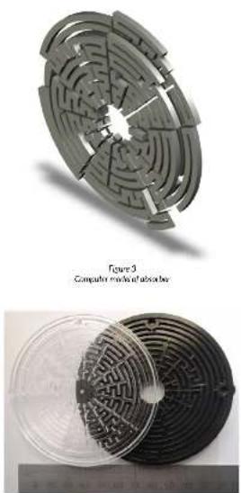
Figures 3 and 4 respectively show a computer model of the absorber and the real thing. Its design borrows from a room acoustics absorber in that it is based around 12 wavelength resonators. Looking rather like a maze, what you can see are 15 separate tubes, folded up to make a circular object. In fact, there are 2 layers, so there are, in total, 30 tubes, each tuned to a different frequency.
natural_image
Technical illustration of a computer module with its abacus, shown from two views: top is circular assembly with internal maze-like patterns, bottom is meshed circular component (no text or symbols)Figure 4 Actual aborder
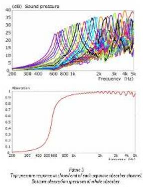
Each tube has a very high Q, which means high absorption over a very narrow band, and the only damping, which is the way the energy is dissipated, comes from the friction between the air moving in the tubes and the tube walls. The frequency spacing is designed so that, when the effects of all the tubes are combined together, the absorption is uniform over a wide band.
Figure 5 shows the pressure response, measured at the closed end of each of the 30 channels, together with the absorption spectrum of the whole absorber.
line
| Frequency (Hz) | Sound pressure (dB) | | -------------- | ------------------- | | 200 | ~0 | | 300 | ~5 | | 400 | ~10 | | 600 | ~20 | | 800 | ~25 | | 1k | ~30 | | 2k | ~35 | | 3k | ~38 | | 4k | ~37 | | 5k | ~36 |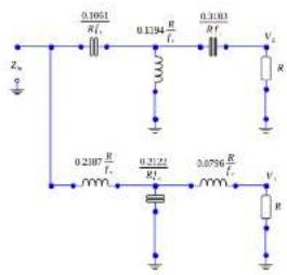
Figure 6 Generalized 3rd-order Butterworth constant-resistance crossover. Units are Ohms, Forade and Hannes. It is cut-off
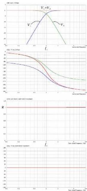
Figure 7
Top: Amplicate and Phase responses of transfer functions V1 (green), V2 (blue) and V1-V2 (red)
Bottom: Ampathode and Phase responses of input impedance
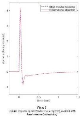
These are steady-state measurements and anyone who is familiar with filters will know that, although the amplitude response of narrow band filters may well add to unity, this usually hides the presence of all-pass phase responses and some time smearing occurs. The system is said to be non-minimum phase. This is the case with the summing of the transfer functions of the separate channels of graphic equalisers and the outputs of two or more drivers fed by a passive speaker crossover network. Such time smearing can readily be shown by impulse measurements, where a change in profile between the exciting signal and that generated by the device(s) indicates time smearing.
line
| time (ms) | Ideal impulse response | Metamotorial absorber | | --------- | --------------------- | -------------------- | | 0.0 | 4.0 | 0.0 | | 0.1 | -1.0 | 0.0 | | 0.2 | 0.0 | 0.0 | | 0.3 | 0.0 | 0.0 | | 0.4 | 0.0 | 0.0 | | 0.5 | 0.0 | 0.0 | | 1.0 | 0.0 | 0.0 | | 1.5 | 0.0 | 0.0 |However, it must be realised that what is being used here is the acoustic impedance, not a transfer function. To take an electrical analogy, consider a passive, constant-resistance network such as that of figure 6.
While the individual low- (V1) and high-pass (V2) transfer functions are minimum phase, the sum of the transfer functions (V1+V2) is not. It is a 2nd-order all-pass. However, the total input impedance (Zin), is a pure resistance, R. As such, it is minimum phase. There is no all-pass (figure 7).
To illustrate that the absorber is indeed minimum-phase and introduces no time smearing, figure 8 shows the impulse response of the tweeter dome movement overlaid with an ideal, minimum phase response. There is virtually no difference.
The tweeter dome movement was chosen because it can be measured close-to, which increases the signal to noise ratio. As it is only valid well below the first break-up mode of the dome and the absorber only works above a certain frequency, both signals were equally band limited to avoid errors.
Coupling the Absorber to the Tweeter Dome
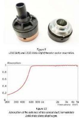
The absorber sits at the rear of the Uni-Q™ driver and is coupled to the tweeter dome by a slightly tapered conical duct, which acts as a waveguide. This waveguide passes through the centre poles of both the tweeter and bass/midrange drivers and has involved a complete redesign of the tweeter magnet assembly to accommodate the wider diameter required for the duct to work properly. The difference in the motor assemblies is shown in figure 9.
A small amount of porous material is placed in the duct, which has the dual effects of reducing the amount of ripple at high frequencies and fine-tuning the knee of the absorption spectrum. Figure 10 shows the absorption spectrum immediately behind the dome.
Tangerine Waveguide
Many acoustic engineers would be so pleased at designing the almost perfect tweeter absorber that they would have rested on their laurels. But speaker design is rather like peeling an onion - remove one layer and there is another one exposed. So it is with the removal of colouration caused by the rear radiation
not being totally absorbed. It exposed a lesser, but still important layer of residual colouration. It turned out that the tangerine waveguide and the dome surround support - both plastic mouldings - were physically deforming at high frequencies. (figure 11)
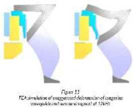
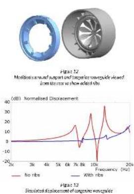
Strengthening ribs were added to both components, which reduced the deformation. Figure 12 shows the actual modified parts (viewed from the rear) and figure 13 illustrates the reduction in displacement. It should be noted that the modified parts have an area comparable to the tweeter dome itself and any movement will add audible colouration to the overall.
For the basic operation of the tangerine waveguide, featured in previous models, see Appendix 3.
line
| Frequency (Hz) | No ribs (dB) | With ribs (dB) | | -------------- | ----------- | ------------- | | 2k | 0 | 0 | | 3k | 0 | 0 | | 4k | 0 | 0 | | 5k | 0 | 0 | | 6k | 0 | 0 | | 7k | 0 | 0 | | 8k | 0 | 0 | | 9k | 0 | 0 | | 10k | -20 | 0 | | 20k | 40 | 10 |Tweeter Gap Damper
One of the problems with constructing a combination driver array like Uni-Q is dealing with the gaps that separate the constituent parts. There is a narrow channel - an annular gap - between the moving midrange voice coil and the static start of the tweeter waveguide. This channel acts as an organ-pipe-like resonator, and is excited by the tweeter output. The resonances modify the response of the tweeter, adding a series of glitches that are not present if the gap is closed off - simulating a perfectly smooth waveguide.
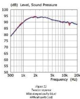
Obviously, this annular gap is necessary to allow the LF/MF cone and voice coil to move, so the solution was to create a cavity between the midrange and tweeter magnets to which this annular gap connected (figure 14). Adding damping to this newly-created cavity was found to be effective in taming the resonances in the annular gap and the removal of the response glitches was immediately apparent as an improvement in detail clarity (figure 15).
This feature - the tweeter gap damper - was first introduced through the R Series (2018), and was a major development that led to birth of the 12th Generation Uni-Q. The addition of MAT and the
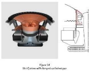
change in tweeter system structure for L550 Meta, however, necessitated a redesign of the tweeter gap damper. Additional work was carried out in regards to the shape of the cavity and the placement of the wedding material - now comprising of two rings - to further improve performance.
line
| Frequency (Hz) | Sound Pressure (dB) | | -------------- | ------------------- | | 500 | 78 | | 1k | 90 | | 2k | 94 | | 5k | 93 | | 10k | 91 | | 20k | 89 |Motor Design
In addition to the tweeter motor system being modified to accommodate the wider duct through its centre pole, other changes were made to provide a more consistent drive to the voice coil.
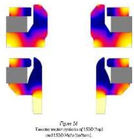
Figure 16 illustrates the difference in tweeter motor design between the original LS50 and the LS50 Meta.
natural_image
Four abstract 3D state diagrams with color gradients, no text or symbols presentOne major change is the sheer size difference of the duct - 2.5x the surface area of that found in the original LS50, increasing the air volume available to the tweeter.
This ensures as much of the sound as possible from
the back of the dome is directed into the metamaterial absorber. but also reduces non-linear distortions caused by air pressure changes behind the tweeter. As a tweeter moves in and out, it compresses and decompresses the air behind it. This negatively affects the excursion characteristics and linearity of the tweeter. The larger the air volume, the lesser the effect.
Also notable is the increased saturation of the steel components of the motor system. The image colour is indicative of the magnetic strength throughout the steel, and dark blue indicates saturation.
Normally the magnetic field in the gap is perturbed by the electric current in the voice coil, which changes the force on the voice coil during every cycle of movement. Perturbation cannot occur if the motor system is saturated and so the force on and therefore the motion of the voice coil more closely follows the input signal.
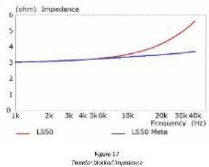
Saturation did result in a drop of flux density in the gap. This was compensated by changing the tweeter voice coil from one to two layers, which would normally lead to an increase in coil inductance, with a progressive loss of sensitivity at very high frequencies. A copper sleeve on the centre pole, which couples inductively to the voice coil, reduces the inductance, even below that of the LS50, as is shown by the blocked coil measurements of figure 17.
line
| Frequency (Hz) | LSSO (ohm) | LSSO Meta (ohm) | | -------------- | ---------- | --------------- | | 1k | 3.0 | 3.0 | | 2x | 3.0 | 3.0 | | 3k | 3.0 | 3.0 | | 4k | 3.0 | 3.0 | | 5k | 3.0 | 3.0 | | 6k | 3.0 | 3.0 | | 10k | 3.5 | 3.2 | | 20k | 4.5 | 3.5 | | 30k | 5.5 | 3.8 | | 40k | 6.5 | 4.0 |Bass/Midrange Motor Design
The design of the motor used in the bass/midrange driver of the Uni-Q driver has also been modified to reduce modulation by the movement of the voice coil, but this time the approach is different from that used for the tweeter, partly because the driver has an overhung voice coil (coil longer than the magnet gap) as opposed to the underhung coil (coil shorter than the magnet gap) of the tweeter, which is always fully in the steel gap.
The inductance of a voice coil presents a couple of challenges. Higher levels of inductance create a larger net magnetic field as the signal passes through the voice coil. This magnetic field causes distortion - the lower the inductance of the voice coil, the lower the net magnetic field is produced, thus lower distortion.
The inductance of the voice coil also tends to change as the coil moves in the gap (modulation). The steel acts as a core to increase the coil's inductance and the amount of steel (and therefore the inductance) varies as the coil position changes. This variance is an issue, as it introduces non-linear distortions into the loudspeaker performance.
As a result, more extensive use is made of auxiliary aluminium parts in LS50 Meta than was the case with the original LS50. The aluminium, although non-magnetic, is conductive and couples inductively to the voice coil. Being a virtual short circuit, it reduces the value of the coil's inductance, which in turn reduces modulation of the flux of the motor system - reducing non-linear distortions.
The LS50 and LS50 Meta motor designs are compared in figure 18. The aluminium parts are coloured light grey.
Where the original LS50 features a small aluminium ring placed between the magnet and voice coil, LS50 Meta sports a much larger version. In addition, another ring has been added to the top. The red fringing in the otherwise blue steel is a measure of the coil modulation and is seen to be much lower in the LS50 Meta.
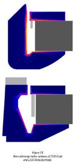
The LS50 Meta motor system also features an undercut pole design to minimise the steel volume and focus the magnetic field more precisely on the voice coil. Also instructive is to measure the voice coil inductance at different frequencies and compare different designs.
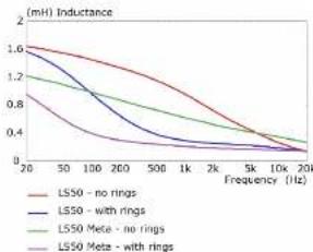
For the measurements in figure 19, the voice coil is blocked (glued in place) at the centre (rest) position. LS50 Meta - with the shorting rings - exhibits much lower inductance than the other designs.
Inductance modulation was also measured at two different frequencies (200Hz and 2kHz) against excursion. Figure 20 clearly shows that the LS50 Meta design, with the shorting rings, exhibits the least variation of inductance against excursion - creating a frequency response that stays balanced, with very little influence from the excursion of the driver.
line
| Frequency (Hz) | LS50 - no rings | LS50 - with rings | LS50 Meta - no rings | LS50 Meta - with rings | | -------------- | --------------- | ----------------- | -------------------- | ---------------------- | | 20 | 1.6 | 1.6 | 1.2 | 0.8 | | 50 | 1.4 | 1.3 | 1.0 | 0.6 | | 100 | 1.2 | 1.1 | 0.8 | 0.4 | | 200 | 1.0 | 0.9 | 0.6 | 0.3 | | 500 | 0.8 | 0.7 | 0.4 | 0.2 | | 1k | 0.6 | 0.5 | 0.3 | 0.1 | | 2k | 0.4 | 0.3 | 0.2 | 0.1 | | 5k | 0.2 | 0.1 | 0.1 | 0.1 | | 10k | 0.1 | 0.1 | 0.1 | 0.1 | | 20k | 0.1 | 0.1 | 0.1 | 0.1 |Figure 19 Bass/mrange blocked valve oil ductance against frequency.
The change in magnet design has had two further advantages. The undercut centre pole gives higher flux density in the gap itself and lower magnetic ringing (figure 21). This results in higher sensitivity of the driver and more linear drive at higher excursions (figure 22).
Looking at figures 18-22 together, we see that the new design gives less modulation of the magnet flux density in the gap, more linear drive, lower voice coil inductance and virtually no change in inductance with voice coil position. The upshot of all this analysis and redesign is a significant reduction in total harmonic distortion (THD) in the frequency range where the ear is at its most sensitive (figure 23).
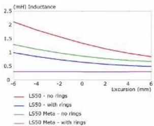
line
| Excursion (mm) | LS50 - no rings | LS50 - with rings | LS50 Meta - no rings | LS50 Meta - with rings | | -------------- | --------------- | ----------------- | -------------------- | ---------------------- | | -6 | 2.0 | 1.3 | 1.4 | 0.5 | | -4 | 1.7 | 1.1 | 1.2 | 0.5 | | -2 | 1.4 | 0.9 | 1.0 | 0.5 | | 0 | 1.2 | 0.8 | 0.9 | 0.5 | | 2 | 1.0 | 0.7 | 0.8 | 0.5 | | 4 | 0.8 | 0.6 | 0.7 | 0.5 | | 6 | 0.7 | 0.5 | 0.6 | 0.5 |Figure 20a
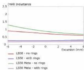
line
| Excursion (mm) | LS50 - no rings | LS50 - with rings | LS50 Meta - no rings | LS50 Meta - with rings | | -------------- | --------------- | ----------------- | -------------------- | ---------------------- | | -6 | 1.0 | 0.2 | 1.3 | 0.2 | | -4 | 0.9 | 0.2 | 1.2 | 0.2 | | -2 | 0.8 | 0.2 | 1.1 | 0.2 | | 0 | 0.7 | 0.2 | 1.0 | 0.2 | | 2 | 0.6 | 0.2 | 0.9 | 0.2 | | 4 | 0.5 | 0.2 | 0.8 | 0.2 | | 6 | 0.4 | 0.2 | 0.7 | 0.2 |Figure 20b Bauschikangewake cell inductance against displacement at 200Hz (figure 20d) and 2kHz (figure 20d).
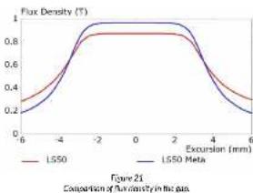
line
| Excursion (mm) | LS50 | LS50 Meta | | -------------- | ---- | --------- | | -6 | 0.2 | 0.2 | | -4 | 0.6 | 0.7 | | -2 | 0.8 | 0.9 | | 0 | 0.8 | 0.9 | | 2 | 0.8 | 0.9 | | 4 | 0.6 | 0.7 | | 6 | 0.2 | 0.2 |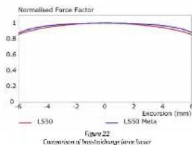
line
| Excursion (mm) | LS50 | LS50 Meta | | -------------- | ---- | --------- | | -6 | 0.8 | 0.8 | | -4 | 0.9 | 0.9 | | -2 | 0.95 | 0.95 | | 0 | 1.0 | 1.0 | | 2 | 0.95 | 0.95 | | 4 | 0.9 | 0.9 | | 6 | 0.8 | 0.8 |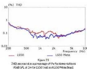
line
| Frequency (Hz) | L550 | L550 Meta | | -------------- | ---- | --------- | | 200 | 1.0 | 1.0 | | 500 | 0.1 | 0.1 | | 1k | 0.01 | 0.01 | | 2k | 0.1 | 0.1 | | 5k | 0.1 | 0.1 | | 10k | 0.1 | 0.1 |Crossover
The topology of the crossover of the LS50 Meta is shown in figure 24. The smoother response of the new tweeter has resulted in fewer components in the HF filter and the remaining series capacitor (C1) is of higher quality.
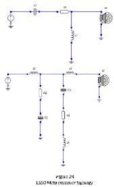
The LF filter is similar to that in the original LS50, but includes an extra low-Q parallel resonance branch (C3-R3-L4) to compensate for the higher sensitivity in the driver's upper midrange due to its lower inductance.
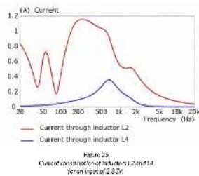
The inductor L4 is the only one in the crossover to have a core. It is vital that only the resistor R3 controls the Q of the branch. To that end, the resistance of L4 (which is subject to change as it heats up when passing current) is kept as low as possible. As the core is a possible source of harmonic distortion if it nears saturation, measurements were taken to relate the current passing through L4 with that passing through L2. Figure 25 shows that it will be seen that the current passing through L4 is much lower and the chances of its core saturating are virtually nil, a fact borne out by the THD measurements of figure 23.
To minimise any coupling between inductors, the three in the LF filter are arranged orthogonally and the HF filter is on a separate board, placed well away from the LF filter.
line
| Frequency (Hz) | Current through inductor L2 | Current through inductor L4 | | -------------- | -------------------------- | -------------------------- | | 20 | 0.8 | 0.0 | | 50 | 0.3 | 0.0 | | 100 | 0.7 | 0.0 | | 200 | 1.2 | 0.0 | | 500 | 1.0 | 0.3 | | 1k | 0.6 | 0.4 | | 2k | 0.4 | 0.2 | | 5k | 0.2 | 0.1 | | 10k | 0.1 | 0.0 | | 20k | 0.0 | 0.0 |Industrial Design
Little has changed from the original LS50, but there are a few detailed changes to the back of the cabinet to improve performance and enhance looks (figures 1 & 26):
• The port opening is now flush with the rear surface, which further reduces turbulence.
- The 4 cavities in the corners for the baffle retention bolts have been eliminated.
- The rear surface is now slightly domed.
- A step transition between the rear panel and the sides of the cabinet has been introduced.
- There is now a soft notch around each binding post.
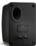
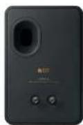
Figure 26
Rear views of LSSO (left and LSSO Meta right)
Specification - LS50 Meta
| Description | Bookshelf Loudspeakers |
| Drive Units | Uni-QTM Driver ArrayLF/MF: Nominal dia. 130mm (5.25 in) magnesium/aluminium alloy coneHF: Nominal dia. 25mm (1 in) aluminium alloy dome vented withMetamaterial Absorption Technology (MAT) |
| Frequency Range (-6dB) 47Hz - 45kHz | |
| Frequency Response (±3dB) 79Hz - 28kHz | |
| Sensitivity (2.83V, 1m) 85dB SPL | |
| Maximum SPL at 1m | 106dB |
| Harmonic distortion | <0.4% 175Hz - 20kHz (90dB SPL, 1m) |
| Crossover frequency | 2.1kHz |
| Nominal Impedance | 8Ω |
| Minimum Impedance | 3.5Ω |
| Dimensions (inc. terminals) | H: 302mm (11.9 in)W: 200mm (7.8 in)D: 278mm (10.9 in) |
| Weight | 7.2kg (15.8 lb) |
Written specifications like these, however useful for comparison, do not fully describe the listening experience.
However good the component parts, voicing the system with the crossover is all-important.
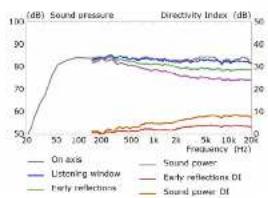
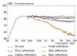
The following graphs, which include additional directivity and early reflection information in line with the research work of Floyd Toole [9][10], show how smooth the response of the LS50 Meta is, indicating a superb listening experience.
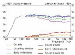
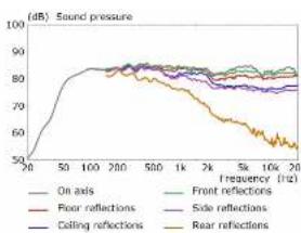
line
| Frequency (Hz) | On axis | Front reflections | Rear reflections | Side reflections | Ceiling reflections | Rear reflections | | -------------- | ------- | ---------------- | ---------------- | ---------------- | ------------------- | ---------------- | | 20 | 50 | 85 | 85 | 85 | 85 | 85 | | 50 | 80 | 85 | 85 | 85 | 85 | 85 | | 100 | 85 | 85 | 85 | 85 | 85 | 85 | | 200 | 85 | 85 | 85 | 85 | 85 | 85 | | 500 | 80 | 80 | 80 | 80 | 80 | 80 | | 1k | 75 | 75 | 75 | 75 | 75 | 75 | | 2k | 70 | 70 | 70 | 70 | 70 | 70 | | 5k | 65 | 65 | 65 | 65 | 65 | 65 | | 10k | 60 | 60 | 60 | 60 | 60 | 60 | | 20k | 55 | 55 | 55 | 55 | 55 | 55 |Appendix 1 - Cabinet
The cabinet construction follows closely that of the original LS50.
Diffraction
Diffraction is the secondary radiation that happens when the wavefront from the driver meets a sharp edge. This reradiation causes what might be described as a mini-echo that time smears the driver's output. The effect varies with angle, but needs to be minimised to maintain clarity.
At very low frequencies, rather like a sea wave wrapping round a small pebble, the sharp edges of the cabinet have little effect - the sound simply wraps around the object in a smooth manner. At very high frequencies, only a minimal proportion of the energy travels along the front baffle, due to the increased directivity of the radiating diaphragm, and the reradiation level is low. In between these extremes, the shape of the cabinet, especially the front baffle, has a marked effect.
Traditionally, it was thought that the edges of the baffle need to be rounded, preferably with a radius similar to the wavelength of the sound. However, detailed research has shown that, if the baffle is curved, the angle at the edge does not have to reach 90 degrees.
for the majority of the diffraction effect to be eliminated. This is extremely fortunate, because fully rounding the corners with a large radius is wasteful of space and not very nice to look at. The front baffle is curved in both directions enough to make diffraction inaudible.
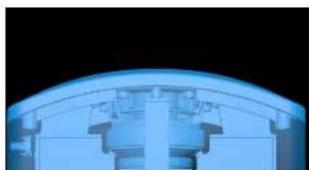
natural_image
Close-up of a curved architectural or mechanical component with blue lighting (no visible text or symbols)Figure 27 Low-attraction Engine
Rigid Bracing/Constrained Layer Damping
The ultimate goal in the design of any speaker is to have all the sound energy coming from the drivers and none from anything else. The cabinet walls are a particular problem as they have a much larger area than the driver diaphragms and their output can be problematic with relatively little flexure. Not only is the sound delayed relative to the direct sound from the drivers, but it's highly distorted and the resulting colouration can be extremely unpleasant.
Vibration of the cabinet walls is excited both by variation in air pressure inside the cabinet and by the reaction force on the driver motor as the diaphragm moves back and forth. This latter force is transmitted via the driver chassis to the cabinet panel.
That the cabinet needs to be there at all may be realised by going back to figure 2. The bass/midrange driver radiates energy to the rear and that energy has to be contained, otherwise the rear radiation will progressively cancel the front radiation as the frequency decreases, and absorbed - which effectively means turning it into heat.
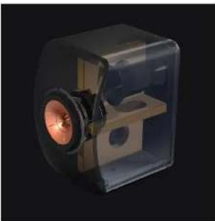
This constraint has traditionally been done by adding bracing. On its own, this has less effect than may be expected from simply considering static stiffness. What it tends to do is shift the problem to higher frequencies. However, the simple expedient of adding a lossy layer between the braces and the cabinet walls absorbs far more energy - Constrained Layer Damping. This lossy material is sandwiched between the bracing and the driver/panel, converting vibration into heat.
natural_image
3D rendering of a transparent cube containing a mechanical component with a central lens and wooden base (no text or symbols visible)Fig. 28 Carshined inner clamped bracing
Appendix 2 - Ports
Ports are used to augment bass response. They have the dual advantage that they enable a lower cut-off frequency than closed-box systems for the same size of enclosure and, within the operating range of the port, the bass driver moves less, thus lowering distortion.
Ports are not without their drawbacks, however.
- They can be a window to resonances in the air cavity inside the cabinet.
- At midrange frequencies, they act rather like an organ pipe and exhibit a series of resonances.
- They can be a source of noise if turbulence is allowed to happen as air vents out at each end of the port (so-called chuffing).
Resonances inside the cabinet
The port is positioned on the rear panel of the cabinet. This has two advantages:
- Resonances inside the cabinet are at relatively high frequencies and the sounds are not directed towards the listener.
- There is more freedom on the rear panel compared to the front in positioning the port so it is placed close to nodes (nulls) of the resonances, so less energy is transmitted through the port.
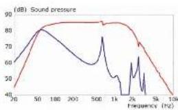
To illustrate this last point, figure 29 shows the difference in output when the port is placed at an antinode and at a node of an internal resonance. For the first of these measurements there is no wadding inside the cabinet, so the effect is made clearer. The resonance can clearly be seen in the total response. When the ports are optimally placed and the wadding added, the resonances are greatly depressed and cannot be detected in the overall response.
Organ pipe resonances
These resonances within the port itself can be drastically reduced if the walls of the port have a degree of flexibility. Instead of the normal rigid plastic, the walls are fabricated from closed-cell foam. Originally developed for the original LS50 loudspeaker, this technique dramatically reduces the pressure variations inherent in these higher frequency resonances and renders them less audible.
line
| Frequency (Hz) | Sound pressure (dB) | | -------------- | ------------------- | | 20 | 40 | | 50 | 80 | | 100 | 85 | | 200 | 85 | | 500 | 85 | | 1k | 70 | | 2k | 50 | | 5k | 70 | | 10k | 40 |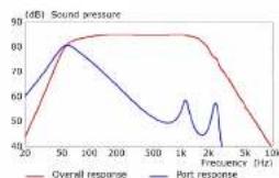
line
| Frequency (Hz) | Overall response | Port response | | -------------- | ---------------- | ------------- | | 20 | 40 | 60 | | 50 | 80 | 80 | | 100 | 85 | 75 | | 200 | 85 | 65 | | 300 | 85 | 50 | | 1K | 85 | 55 | | 2K | 80 | 60 | | 5K | 70 | 40 | | 10K | 40 | 40 |Figure 29 Simulated comparison of the port and total speaker output with unamined (front) and optimised (back) port location
Figure 30 illustrates this technique using Finite Element Analysis (FEA), where the colour scale from green through to red indicates the level of air pressure.
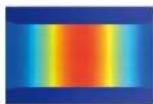
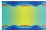
Figure 30
Comparison of the Full-Electric mounted pressure magnetude in the part of the feet standing walls with right walls (top) and flexible walls (bottom).
Turbulence
This occurs at both ends of the port as the air exits the port either to the open air or the air enclosed within the cabinet. The solution is to flare both ends of the port (figure 31). The progressive expansion of the air afforded by the flaring reduces turbulence and thus audible chuffing. It should be noted that, if turbulence is allowed to develop, not only is it audible, but the performance of the port changes with sound level, impairing the dynamic range of the loudspeaker.
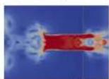
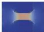
Figure 31 - Flow pressure contour of straight port (top) and flared port (bottom)
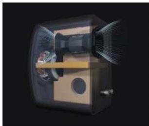
Figure 32 shows the final design of the port located inside the LS50 Meta cabinet.
natural_image
Cross-sectional diagram of a mechanical device with internal components and no visible text or symbolsFigure 32 - Offset flexible port located inside the 1550 Meter
Appendix 3 - Uni-Q™
The Uni-Q array has been the mainstay of virtually all KEF loudspeakers since its introduction in 1988. It delivers the holy grail of loudspeaker design in that all sound appears to emanate from the same point in space. Coaxial loudspeakers had been around for many years before the introduction of Uni-Q, but the tweeter was never time aligned with the midrange or bass/midrange driver it was partnered with. Either the tweeter was in front of the larger driver, which brought the added disadvantage that the tweeter impaired the response of the driver it was in front of, or it was well behind. With Uni-Q, both drivers have their acoustic centre at the same point and the larger driver acts as a waveguide for the tweeter. The result is that the blend between the two units is virtually seamless in terms of both response and dispersion. The two units together can be regarded as a single driver without the performance shortfall that would be suffered by a true single driver covering such a wide frequency range.
Over the intervening years, the Uni-Q concept has been progressively refined. The midrange cone shape has been optimised to create just the right amount of dispersion at all frequencies and innovations such as the tangerline waveguide have improved the performance of the tweeter. Uni-Q is simple in concept, but tricky to implement in practice. Here are some of the techniques previously developed and carried over to this model.
Tweeter
Diaphragm
The dome diaphragm itself is aluminium. More exotic materials - diamond and beryllium for example - are sometimes used in an effort to increase stiffness and push the pistonic region of the tweeter to the limits of human hearing. But this can be done with aluminium at far lower cost, providing some ingenuity is used in designing how the dome is constructed.
The optimum dome shape for waveguide loading is a spherical cross-section, but the optimal shape for stiffness is an elliptical cross-section. Both were combined into the patented KEF Stiffened Dome. A one-piece elliptical dome and voice coil former is deep drawn and the centre removed. This is capped by a spherical dome and a very stiff triangular section is formed where the two parts join.
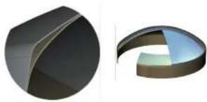
natural_image
Two 3D geometric shapes: a solid black octagon and a curved segmented shape with a light blue interior (no text or symbols)Figure 32 3D CAD sectional views of the newer dome and extended former that must to form a triangular offering member at the dome edge
Tangerine Waveguide
The interface between the radiating dome of the tweeter and the waveguide formed by the midrange dome is extremely critical. Ideally, the diaphragm should be a pulsating dome, which would involve the radius of curvature changing. This is not possible and the motion is in the same direction all over the surface of the dome. To compensate for this non-ideal situation and taking a leaf out of the design of compression drivers, the Tangerline Waveguide was developed to restore correct coupling between the dome and the whole waveguide.
The improved coupling at high frequencies above 5kHz brings with it a useful increase in sensitivity and a reduction in the height of the first resonance peak, illustrated by figure 34.
Figure 35 shows the tangerine waveguide in place in the Uni-Q array. Note that this is the basic operation of the tangerine waveguide that is carried over from previous models. It is enhanced by the extra stiffening described in the new features section (figure 12).
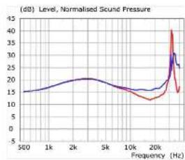
line
| Frequency (Hz) | Normalised Sound Pressure | | -------------- | ------------------------- | | 500 | 15 | | 1k | 18 | | 2k | 20 | | 5k | 18 | | 10k | 15 | | 20k | 35 | | 25k | 40 |Figure 3d FEA Simulation of bicenter output without bicgular waveguide (rod with tangerine waveguide (ole))
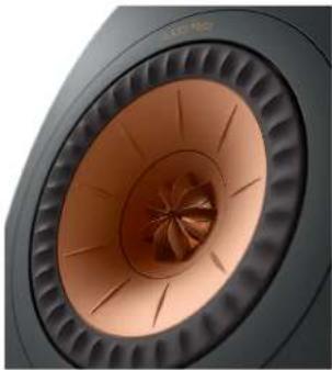
natural_image
Close-up of a black speaker grille with concentric fan-shaped blades and central hub (no text or symbols visible)Figure 35 Tungine transgrade in position no top of twreeler chume
Bass/Midrange driver
Diaphragm
The cone is formed from a magnesium/aluminium alloy. Like the tweeter dome, it serves to provide the necessary stiffness to give pure pistonic motion over the driver's working range. The stiffness is increased by the radial embossing in the cone profile. Nevertheless the cone is still prone to high-Q break-up, but this time in the frequency range covered by the tweeter.
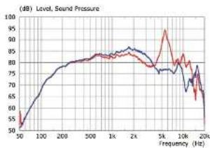
Being within the human audio range, the break-up has to be tamed, rather than putting it out of hearing range. This is done by introducing a flexible, decoupling material between the cone neck and the voice coil former.
The high-Q resonances are tamed to the extent that they may be properly attenuated by the crossover and not break through the tweeter output. Figure 37 illustrates the improvement in the unit's response as a result of using the lossy interface. Mechanical correction is far better than equalising the peaks with the crossover. The latter does not subdue peaks in the THD at sub-multiples of the fundamental.
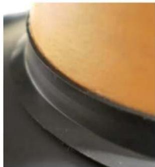
natural_image
Close-up of a smooth, curved surface with orange-brown top layer and black base (no text or symbols visible)Figure 26 Cone Neck Control interface between voice call former and driver cone.
Z-Flex Surround
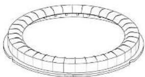
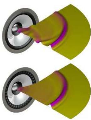
The midrange cone and outer surround form a waveguide for the tweeler and the normal roll surround is not ideal in this respect, especially close to the driver's axis, where symmetry has a large effect.
The Z-Flex surround has been specially designed to allow the necessary movement of the bass/midrange cone, but provide a low profile to allow the cone and surround to act together more accurately as a tweeter waveguide.
It will be seen that the outer vertical wall of the surround is another possible source of discontinuity, so the outer trim ring is part of the whole design, giving a smooth transition all the way from the tweeter diaphragm to the front baffle.
line
| frequency (Hz) | Sound Pressure | | -------------- | -------------- | | 50 | 50 | | 100 | 65 | | 200 | 75 | | 500 | 80 | | 1k | 85 | | 2k | 80 | | 5k | 95 | | 10k | 75 | | 20k | 60 |Figure 37 Effect of lossy interface on response of LF/MF driver
natural_image
Technical line drawing of a circular mechanical component with segmented outer ring (no text or symbols)Figure 38 Z-Flex surrounded - line drawing
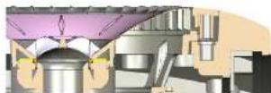
Figure 39
Cross section of complete Uni-Q driver and trim ring
natural_image
Two identical 3D-rendered mechanical components with metallic balls and purple connectors, no text or symbols visible.Figure 40 FDA simulated booster impulse response with half-roll surround (top) and 7 Flex surround/loaf band Note the implement response, especially close to the mill's axis
Summary
As can be deduced from reading this paper, there is a lot of technology packed into the LS50 Meta, both new and existing - a culmination of many years of KEF innovation and acoustic expertise.
All this technology, although tackling legitimate sound reproduction problems in a scientifically logical manner, is of little use if the listener is not brought ever closer to sound Utopia - getting more and more enjoyment and fulfilment from the listening experience.
This is probably the best compact passive monitor that is available today. This is a bold claim, but valid not just because of the engineering expertise packed into it, but also because the engineers responsible for its design, often frustrated musicians, are fully aware of what sounds good, what sounds bad and what shortcomings the ear is able to gloss over.
References
[1] M. Yang, S. Chen, C. Fu and P. Sheng, "Optimal sound-absorbing structures," Mater. Horiz., vol. 4, pp. 673-680, 2017.
[2] S. Degraeve and J. Oclee-Brown, "Metamaterial Absorber for Loudspeaker Enclosures," 148th Audio Eng. Soc. Convention, 2020.
[3] KEF Research and Development, *R Series White Paper, 2018.
[4] KEF Research and Development, "The Reference White Paper," 2013.
[5] M. Dodd and J. Oclcc-Brown, "New methodology for the Acoustic Design of Compression Driver Phase Plugs with Concentric Annular Channels," J. Audio Eng. Soc., vol. 57, no. 10, pp. 771-787, Oct 2009.
[6] M. Dodd and J. Oclce-Brown, "A New Methodology for the Acoustic Design of Compression Driver Phase Plugs with Radial Channels," 125th Audio Eng. Soc. Convention, 2008.
[7] M. Dodd, 'The development of the KEF LS50, a compact two way loudspeaker system,' International Conference, Helsinki, Finland, 2013.
[8] A. Salvatti, A. Devantier and D. J. Button, "Maximizing Performance from Loudspeaker Ports," J. Audio Eng. Soc., vol. 50, no. 1/2, pp. 19-45, Jan. 2002.
[9] F. E. Toole, "Loudspeaker Measurements and Their Relationship to Listener Preferences: Part I," J. Audio Eng. Soc., vol. 34, no. 4, pp. 227-235, Apr. 1986.
[10] F. E. Toole, Sound Reproduction, The Acoustics and Psychoacoustics of Loudspeakers and Rooms, Amsterdam; Boston: Elsevier, 2008.
LS50 Wireless II
natural_image
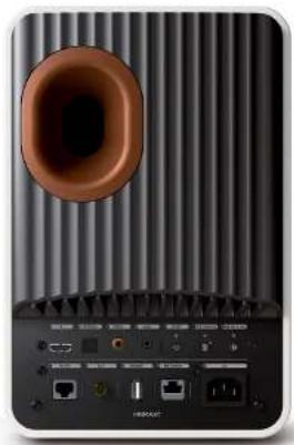
Top-down view of a black speaker grille with a circular vent and external ports (no visible text or symbols)Figure 41 Primary Speaker Rear Panel
natural_image
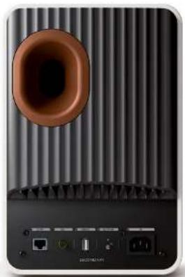
Back view of a black and white electronic device with ventilation grilles and a speaker grille (no visible text or symbols)Figure 42 Secondary Speaker Raw Plate
Overview
The active LS50 Wireless II incorporates all the technology described for the passive LS50 Meta, plus a few extras that either add to the presentation of the music - making it even more accurate - or add to the functionality.
The electronics, mounted on the back, includes two channels of power amplification (one channel for each driver and each of higher power than the original LS50 Wireless) and the KEF Musical Integrity Engine (MIE). This is essentially custom Digital Signal Processing (DSP) that allows the acoustic engineer to do far more than is possible in any passive design.
Each stereo pair comprises a Primary and a Secondary speaker. The former incorporates adjustments applicable to both speakers, such as bass extension, room acoustic compensation, source selection and placement/EQ.
Bass may be extended to lower frequencies than is limited by the usual passive cabinet-size/sensitivity trade-off, the balance may be adjusted for speaker position and room acoustics and the all-pass delay inherent in passive crossovers may be eliminated.
All adjustments are made using a smartphone app. This is available for both iOS and Android devices and is a free download either from the Apple App Store or the Google Play Store as appropriate.
Inputs
All inputs are fed to the Primary speaker (figure 43). The six choices available are:
- eARC PCM at up to 192kHz/24 bit - HDMI (TV) socket
- S/PDIF at up to 96kHz/24 bit - TOSLINK Optical socket
-
S/PDIF at up to 192kHz/24 bit - RCA Phono (coax) socket
-
Analogue stereo - Aux 3.5mm stereo jack socket
-
Network - Wireless (2.4GHz or 5GHz) and Wired (RJ-45 socket and CAT 6 cable) supporting up to 384kHz/24bit, DSD256, MQA
-
Bluetooth 4.2
Selection is made using the smartphone app, the controls on the top of the Primary speaker or the supplied remote control.
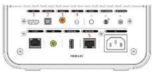
Figure 43 Primary Speaker Inputs
Connection between Primary and Secondary
The two speakers may be connected together either wirelessly or hard-wired.
LSSO Wireless II is pre-paired at the factory for easy setup in wireless mode. The wireless transmission is totally independent of the local Wi-Fi signal. The miniscule delay (2.9ms) between the primary and secondary speakers in this mode is automatically accounted for, through an equal delay applied to the primary speaker. Finally, the wireless connection resamples all audio to 96kHz/24 bit.
The wired interspeaker connection uses CAT-6 cable, plugged into the relevant sockets on the rear of the speakers. Cable mode must also be enabled in the KEF Connect app settings menu. In this mode, all audio signals are resampled to 192kHz/24 bit.
Streaming support
Wireless streaming supports the following:
AirPlay 2
Google Chromecast
ROON Ready (via future firmware update)
UPnP compatible
Bluetooth 4.2
The following music streaming services are also supported (dependent on territory):
Spotify (via Spotify Connect)
Tidal
Qobuz
Deezer
Amazon Music
QQ Music via QPlay
Internet Radio
Podcast
flowchart
graph TD
    A["WE 2.40E+5.5GHz"] --> B["Internet"]
    B --> C["Optical SFPB + 30MHz"]
    C --> D["Digital energy"]
    D --> E["User Equalization"]
    D --> F["Phase correction"]
    D --> G["Consumer"]
    D --> H["Subscale Mining"]
    D --> I["Subscale DAC"]
    E --> J["Micro-solutions secondary DMS"]
    F --> K["Micro-solutions secondary DMS"]
    G --> L["Micro-solutions secondary DMS"]
    H --> M["Micro-solutions secondary DMS"]
    I --> N["Micro-solutions secondary DMS"]
    C --> O["Streaming and Data: PCM + 30MHz + 200mA / 100mA"]
    O --> P["USB"]
    P --> Q["PSU A solution and sharing"]
    P --> R["PSU B analysis and testing"]
    Q --> S["Class III 250V"]
    R --> T["Class IV 750V"]
    S --> U["HP DAC"]
    T --> V["HP DAC"]
    U --> W["Power Supply"]
    V --> X["Power Supply"]
    W --> Y["Power Supply"]
    X --> Z["Power Supply"]
    Y --> AA["Power Supply"]
    Z --> AB["Power Supply"]
Figure 3.4 - Black diagram of Primary Electronics
flowchart
graph TD
    A["PSU-A"] --> B["PSU-B"]
    B --> C["CPU AD 200W"]
    B --> D["I/O I/O"]
    B --> E["I/O U 200W"]
    C --> F["HP DAC"]
    D --> G["I/O DAC"]
    F --> H["Digital amplification"]
    G --> H
    H --> I["User Qualification"]
    H --> J["Phase interaction"]
    H --> K["Conversion"]
    H --> L["Supercharger Monitoring"]
    L --> M["Subsupercharger DAC"]
    I --> N["Internet connection from secondary drive"]
    J --> N
    K --> N
    L --> N
    M --> N
    N --> O["Internet connection from secondary drive"]
Figure 45 - Black diagram of Secondary Electrons
flowchart
graph TD
    A["1. Product quality based on price and cost of sales"] --> B["2. User ratings: adjusted to 10%"]
    B --> C["3. Rating changes: adjusted to 10%"]
    C --> D["4. Product quality: adjusted to 10%"]
    D --> E["5. Rating changes: adjusted to 10%"]
    E --> F["6. Product quality: adjusted to 10%"]
    F --> G["7. Rating changes: adjusted to 10%"]
    G --> H["8. Product quality: adjusted to 10%"]
    H --> I["9. Rating changes: adjusted to 10%"]
    I --> J["10. Product quality: adjusted to 10%"]
    J --> K["11. Rating changes: adjusted to 10%"]
    K --> L["12. Product quality: adjusted to 10%"]
    L --> M["13. Rating changes: adjusted to 10%"]
    M --> N["14. Product quality: adjusted to 10%"]
    N --> O["15. Product quality: adjusted to 10%"]
    O --> P["16. Product quality: adjusted to 10%"]
    P --> Q["17. Product quality: adjusted to 10%"]
    Q --> R["18. Product quality: adjusted to 10%"]
    R --> S["19. Product quality: adjusted to 10%"]
    S --> T["20. Product quality: adjusted to 10%"]
Figure 45 - DGP Denals
DSP Processing
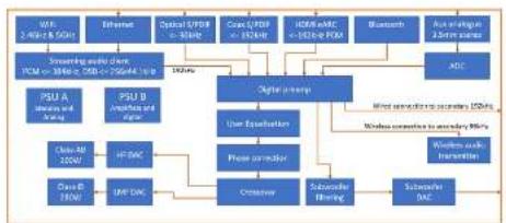
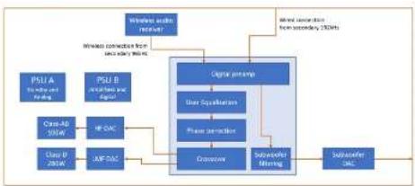
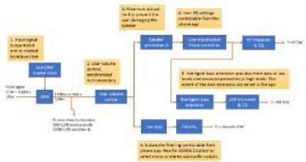
Figures 44 & 45 show block diagrams of the electronics in the Primary and Secondary speakers respectively. All settings are controlled from the smartphone app and applied equally to both speakers.
DSP allows much finer control of the signals reaching the drivers than with a passive crossover, and the L550 Wireless II crossover has been redesigned from the passive version to take advantage of this. Bass cut-off, although still 4th order, has a less rounded corner because there is more level adjustment. By themselves, these filters still result in an all-pass response. However, there is no interaction between the crossover and the driver impedance in the case of active crossovers, leading to better consistency from sample to sample. The all-pass characteristic may be eliminated by the Phase Correction stage and this will be discussed in greater detail in a subsequent section of the paper.
EQ Settings
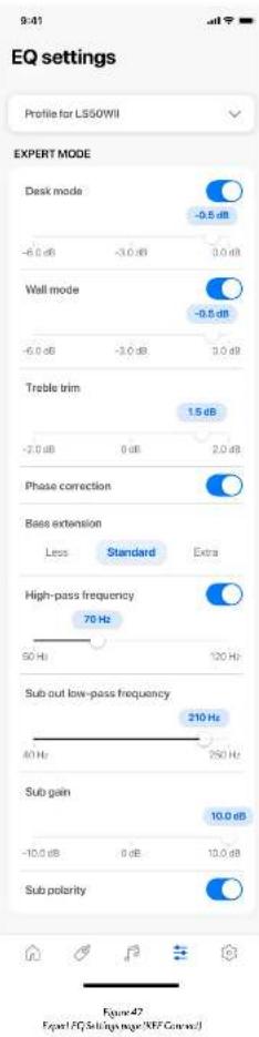
The KEF Connect app allows the listener to make EQ adjustments (Figure 47) based on the listening environment and speaker position.
EQ settings are available in both Basic and Expert modes. Both feature largely the same settings, with the main difference being the way parameters are presented - generally distances for Basic and decibels for Expert.
Desk & Wall Modes
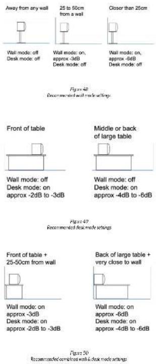
These two modes are used in conjunction to equalise for the method of mounting. Below the on/off toggle is a slider showing the selected value. The line below the slider shows the applicable range. However, the mechanism of nearby reflections is very complicated and simple level settings are only an approximate solution. We would always recommend stand mounting, well away from walls for optimum results. Figures 48-50 show some recommended settings.
Phase correction
As stated before, the basic crossover introduces an allpass into the speaker's response. This does not impinge the magnitude response, which may still be smooth and flat, nor does it affect the directivity, but it does introduce some phase distortion with its accompanying time delay.
However, it is possible, with an active crossover, to compensate for this phase distortion and, if the Basic mode setup is used, this phase compensation is applied by default; the toggle switch is only provided in Expert mode. This enables listeners to hear the difference - which is subtle, but there. There is also a small amount of delay involved with the correction. This extra delay is unlikely to be a problem (see the later section - Syncing with Vision), but the overall latency can be reduced if necessary by switching the correction off.
At this point, it is worth emphasising just how well the Uni-Q principle lends itself to this type of correction - better even than physically separated drivers that are staggered to correct for time delay on axis.
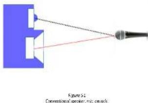
Here is a conventional speaker with the drivers mounted on a stepped baffle so that the distances to the measuring microphone on axis (red for the bass driver, black for the tweeter) are equal.
Treble Trim
This is used to compensate an over-lively (lots of glass/flat surfaces) or over-dead (lots of soft furnishings, curtains) room acoustic. The former requires a modicum of treble cut, whilst the latter requires boost.
Best results are found by ear.
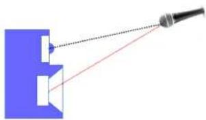
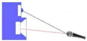
Now, move the microphone up or down and it is apparent that the distances of the two drivers to the microphone are no longer equal.
natural_image
Diagram showing a laser beam projecting onto a blue mechanical component (no text or symbols)Figure 32 Conventional speaker, mic. above axis
natural_image
Diagram showing a camera lens projecting onto a speaker (no text or symbols present)Figure 50 Conventional speaker, mic. below axis.
Even measuring off axis in the horizontal plane results in unequal path differences once the angle is large enough that the radiation from the bass driver does not travel directly to the microphone, but has to travel first to the front of the cone.
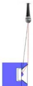
Conventional speaker, mic. horizontally off oics.
The result is that any phase correction in the crossover is only valid directly on axis. In fact, any blending at all of the two drivers suffers phase distortion off axis.
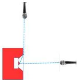
Not so with a Uni-Q combination; the two drivers remain at the same point in space and have the same distance to the microphone, whatever the angle of measurement.
natural_image
Pure diagram of a mechanical or optical setup with no visible text, numbers, or symbolsFigure 55 Unit Q speaker on & off con
Having established just how suitable a Uni-Q speaker is for phase correction, let's see how effective the process is. Here is an input signal - a square wave of 1kHz:
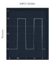
Figure 56
Input signal - 1MHz square wave
This is how the output of the speaker would look with the phase correction switched OFF:
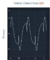
Figure 57
Speaker output - Phase Connection OFF
And this is how it looks with the phase correction switched ON:
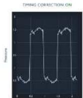
Time - ms
Figure 58
Speaker output: Phase Connection ON
Bass Extension
There are three settings, which should be chosen in conjunction with the room acoustics. The "Less" setting is similar to the natural bass extension of the passive version, giving a cut-off frequency of 46Hz (-6dB). The "Standard" and "Extra" settings give cutoff frequencies of 43Hz and 40Hz respectively.
Normally, the "Extra" setting will be chosen, unless there is a particularly bad room resonance around 30-40Hz, where one of the higher cut-off settings will compensate.
In addition, there is a dynamic bass stage that limits the driver excursion whatever the setting. This prevents excessive distortion and protects the driver from possible damage. The application is practically unnoticeable - however the effect is creating a loudspeaker that sounds larger than it actually is.
Should the user prefer to be unbounded by the limitations of a small bass driver, there is always the option of adding one or two subwoofers.
Adding a Subwoofer
Either one or two subwoofers may be added to reinforce the bass of the audio system.
Each speaker (Primary or Secondary) has a Subwoofer Out socket (RCA Phono). The signal sent to both subwoofer outputs is a summed mono signal.
A crossover between the LS50 Wireless II and the subwoofer is provided and the crossover frequency is set within the app. There is no choice of filter shape - it is always a 4th-order Linkwitz Riley giving -6dB at the cut-off frequency and a flat in-phase total response. If there is any low-pass filter supplied with the subwoofer, it should be bypassed if possible or, if not, the frequency should be set to the highest possible.
The choice of crossover frequency is something of a compromise. The higher it is, the less the excursion demands on the LSSO and the louder the whole system can play. However, if a mono subwoofer output is selected and the crossover frequency is too high, some of the stereo information is lost. 80Hz is usually considered the highest to avoid any perception of loss of stereo information and the lower it is the better in this respect.
In Basic setup mode, the cut-off frequencies of the high-pass to the LS50 Wireless II and the low-pass to the subwoofer(s) are always the same and this is normally the course to follow. However, some subwoofer's do not have a flat response and different cut-off frequencies may give better results. Having different frequencies requires the user to use Expert mode for setup.
Should the subwoofer have an inverting amplifier (rare) or be sited well away from the LS50 Wireless II such that the output is not in-phase with that of the LS50 Wireless II at crossover, there is the option to invert the signal to the subwoofer. In this case the appropriate toggle should be set to ON. More usually it is set to OFF. The correct setting will provide a fuller sound.
If no subwoofer is used the high-pass filter to the L550 Wireless II should be bypassed by switching the toggle in the app to OFF.
The correct sub gain setting depends on several factors such as the sensitivity of the subwoofer and how many are used. The correct balance may be set by ear.
Syncing with Vision
Should the speakers form part of a home theatre installation, where the programme content is audiovisual, the thorny question of the sound syncing with the picture (so-called lip-syncing) must be addressed.
The all-pass characteristic of the bass/midrange to tweeter crossover adds delay to the tweeter, so any correction, if it is to be causal, must delay the whole signal. Additionally, wireless transmission adds some delay. It is important that all this inherent delay does not lead to the perception of mis-syncing, even if theoretically it is impossible to keep everything absolutely together for all settings.
The Advanced Television Systems Committee (ATSC) recommends that the sound to vision delay tolerance is between -15ms to +45ms if lip-syncing is to be unnoticeable. The maximum delay through the speaker is comfortably less than 6ms and so lip-syncing should not be a problem, whatever the settings chosen in the app.
Firmware
From time to time, like any software-controlled device, it will be necessary to update the LS50 Wireless II
firmware, to improve security, add functionality or correct bugs.
Fortunately, the user needs to do nothing. If there is an update available, it will be automatically downloaded from our servers overnight, if the devices are either fully on or in standby.
If preferred, users can manually download updates at a time to suit them using the app. It is also not necessary for the interspeaker cable to be connected.
The KEF Connect app will also receive updates, the process of updating/setting automatic updates will be dependant on the smart device.
Power Amplification
As a true active loudspeaker, LS50 Wireless II features four individual amplifiers - one for each drive unit in the system. These sit after the crossover, meaning that each amplifier receives only the frequencies destined for the corresponding driver. This differs from a passive or powered system, where the crossover comes after the amplification.
A significant benefit from a design standpoint is that different amplifiers can be explored for each drive unit. Through intensive computer modelling and listening tests, KEF engineers were able to develop amplification that is perfectly matched for the frequencies - and drivers - at hand.
LS50 Wireless II features the same amplifier classes as the original LS50 Wireless - Class AB for the tweeter and Class D for the midrange/bass driver. However, a number of changes have been carried out, owing to improved R&D and driver improvements.
The Class AB high frequency amplifier sports a totally new topology - not only providing a higher output, but distortion and dynamic capabilities have been further enhanced over the original. The Class D mid/low frequency amplifier has also seen a significant increase in power output.
Summary
All too often, active speakers simply add power amplifiers and active crossovers to a passive design, but there is much more that active drive can offer.
This speaker takes an already excellent passive design and benefits from all the acoustic technology packed into it. The inherent benefits of Uni-Q are improved upon even further through the inclusion of Phase Correction, whilst the lack of a physical crossover eliminates what can be a significant source of distortion.
LS50 Wireless II also represents a loudspeaker system equally driven by the concept of 'Let You Be You.'
LS50 Wireless II does not aim to change the way someone experiences their music, but is designed to elevate the individual's unique situation through access to a plethora of music services and personalised EQ settings. Further features and improvements, where developed, will be available through easy to perform firmware updates.
natural_image
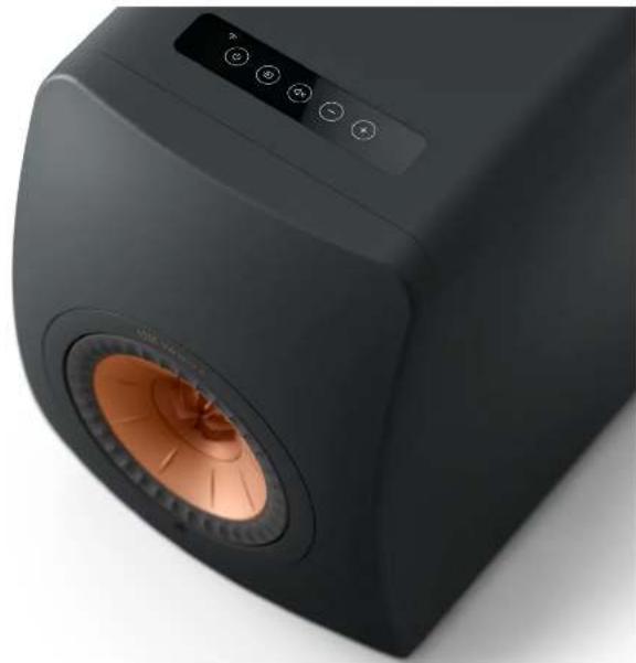
Close-up of a black square electronic device with a speaker grille and control panel (no visible text or symbols)Specification - LS50 Wireless II
| Description | Wireless HIFI Speakers |
| Drive Units | Uni-QTM Driver ArrayLF/MF: Nominal dia. 130mm (5.25 in) magnesium/aluminium alloy coneHF: Nominal dia. 25mm (1 in) aluminium alloy domevented with Metamaterial Absorption Technology (MAT) |
| Frequency Range (-6dB) 47Hz - 45kHz (Less)43Hz - 45kHz (Standard)40Hz - 45kHz (Extra) | |
| Frequency Response (±3dB) | 53Hz - 28kHz (Less)48Hz - 28kHz (Standard)45Hz - 28kHz (Extra) |
| Maximum SPL at 1m 108dB (full range, no subwoofer) | |
| Harmonic distortion <0.4% 175Hz - 20kHz (90cB SPL, 1m) | |
| Crossover frequency 1.9kHz | |
| Power Input 100-240VAC 50/60Hz | |
| Minimum Impedance 3.5Ω | |
| Power Consumption 200W (operating)< 2.0W (standby) | |
| Power Amplifiers LF/MF: 280W Class DHF: 100W Class AB | |
| Input Impedance 50kΩ | |
| Dimensions H: 305mm (12.0 in)W: 200mm (7.9 in)D: 311mm (12.2 in) | |
| Weight | Primary: 10.1kg (22.2 lb)Secondary: 10.0kg (22.0 lb) |
| Supported Formats (all Inputs) | MP3, M4A, AAC, FLAC, WAV, AIFF, ALAC, WMA, LPCM and OggVorbis |
| Supported Formats (extra on network Inputs only) | MQADSF: DSD64, DSD128, DSD256DFF: DSD64 |
line
| Frequency (Hz) | On axis | Front reflections | Floor reflections | Side reflections | Ceiling reflections | Rear reflections | | -------------- | ------- | ---------------- | ---------------- | --------------- | ------------------ | ---------------- | | 20 | 50 | 80 | 80 | 80 | 80 | 80 | | 30 | 80 | 80 | 80 | 80 | 80 | 80 | | 100 | 90 | 80 | 80 | 80 | 80 | 80 | | 200 | 90 | 80 | 80 | 80 | 80 | 80 | | 500 | 90 | 80 | 80 | 80 | 80 | 80 | | 1k | 90 | 80 | 80 | 80 | 80 | 80 | | 2k | 90 | 80 | 80 | 80 | 80 | 80 | | 5k | 90 | 80 | 80 | 80 | 80 | 80 | | 10k | 90 | 80 | 80 | 80 | 80 | 80 | | 20k | 90 | 80 | 80 | 80 | 80 | 80 |
- CONTENTS CONT'D
- Introduction
- Philosophy
- LS50 Meta
- Tweeter
- Metamaterials
- Tweeter Metamaterial Absorption Technology
- Coupling the Absorber to the Tweeter Dome
- Tangerine Waveguide
- Tweeter Gap Damper
- Motor Design
- Bass/Midrange Motor Design
- Crossover
- Industrial Design
- Appendix 1 - Cabinet
- Diffraction
- Rigid Bracing/Constrained Layer Damping
- Appendix 2 - Ports
- Resonances inside the cabinet
- Organ pipe resonances
- Turbulence
- Appendix 3 - Uni-Q™
- Diaphragm
- Bass/Midrange driver
- Z-Flex Surround
- Summary
- References
- LS50 Wireless II
- Overview
- Inputs
- Connection between Primary and Secondary
- Streaming support
- DSP Processing
- EQ Settings
- Desk & Wall Modes
- Phase correction
- Treble Trim
- Bass Extension
- Adding a Subwoofer
- Syncing with Vision
- Firmware
- Power Amplification
Brand : KEF
Model : LS50C
Category : Pregnant