
MCM-8 II - Audio Mixer Heritage Audio - Free user manual and instructions
Find the device manual for free MCM-8 II Heritage Audio in PDF.


| Product Type | 8-Channel Microphone Preamp |
| Number of Channels | 8 |
| Form Factor | 19" Rackmount, 1U |
| Dimensions (W x D x H) | 48.3 cm x 16.5 cm x 4.4 cm (19" x 6.5" x 1.75") |
| Weight | 5.2 kg (11.5 lbs) |
| Power Supply | Internal, 100-240 VAC, 50/60 Hz |
| Gain Range | +12 dB to +70 dB per channel |
| Phantom Power | +48 V individually switchable per channel |
| Polarity Invert | Yes, per channel |
| High-Pass Filter | 80 Hz, 12 dB/octave per channel |
| Input Connectors | XLR (balanced) per channel |
| Output Connectors | DB-25 (balanced) for 8 channels |
| Frequency Response | 20 Hz - 20 kHz ±0.5 dB |
| THD+N | < 0.005% at 1 kHz, +4 dBu output |
| EIN (Equivalent Input Noise) | -125 dBu typ. (A-weighted) |
| Maximum Input Level | +26 dBu (at minimum gain) |
| Maximum Output Level | +28 dBu balanced |
| Front Panel Controls | Gain knob, phantom power switch, polarity switch, HPF switch per channel |
| LED Indicators | Signal present (-20 dBu) and peak (+10 dBu) per channel |
| Construction | All-metal chassis with steel rack ears |
| Cleaning | Use dry cloth; avoid liquids and solvents |
| Safety | Class I equipment; ensure proper grounding; do not open chassis |
| Spare Parts & Repairability | Contact Heritage Audio for authorized service |
| General Information | All-discrete Class A preamp design with Carnhill transformers |
Frequently Asked Questions - MCM-8 II Heritage Audio
User questions about MCM-8 II Heritage Audio
0 question about this device. Answer the ones you know or ask your own.
Ask a new question about this device
Download the instructions for your Audio Mixer in PDF format for free! Find your manual MCM-8 II - Heritage Audio and take your electronic device back in hand. On this page are published all the documents necessary for the use of your device. MCM-8 II by Heritage Audio.
USER MANUAL MCM-8 II Heritage Audio
MCM-8 II
PRELIMINARY USER GUIDE v1.0

*Modules 73 JR II not included
© 2018 Heritage Audio S.L. is the solely owner of the copyright of all information and drawings contained in this manual which are not to be copied or reproduced by any means or disclosed in part or whole to any third party without written permission.
Heritage Audio reserves the right to alter specifications without notice. The information in this manual has been carefully checked and is believed to be accurate at the time of publication. However, no responsibility is taken by us for inaccuracies, errors or omissions nor any liability assumed for any loss or damage resulting either directly or indirectly from use of the information contained within it.
In 2015, Heritage Audio set a new standard in 500 Series enclosures with the addition of the OST technology. Further, we introduced the MCM8, a true transformer-based voltage summing mixer for 500 Series modules.
Hundreds of units later, we have taken all our customer's feedback and included it in the new version, the MCM8 II.
The main differences in between this version and its predecessor are:
- Extra 500 series button per channel, allowing to bypass the 500 series module when mixing if desired. It also allows for quick comparisons in between processed/unprocessed signals. It also makes using the mixer with empty slots quite easier. Just un pressing the 500 button allows for this type of operation.
- Significant lower noise: A highly innovative, new quasi-balanced voltage summing topology sets the noise floor of the new MCM8 II touching the theoretical minimum. No more hiss into your mixes!
INTRODUCTION
The MCM-8 II is an OST ^TM 8 channel 500 Series Enclosure WITH mixer functions.
OST is a Heritage Audio proprietary technology which eliminates module's interaction through the power supply feeding each slot with independent supply stages.
The mixer follows a passive voltage summing topology, having the gain loss restored by a classic '73 type class A output stage.

*Modules 73 JR II not included
Upper row on the front panel is dedicated to the 8 mixer's main inputs.
Controls per channel are as follows:
- ON: When pressed, the output of the slot is added to the mix bus. When depressed, it's muted.
- "500": When pressed, the signal going to the mixer section is taken from the output of the 500 series module, while when not pressed, it is taken from the input of the enclosure. This allows bypassing the module when summing, or using the mixer with an empty slot.
- FADER: Attenuates the signal sent to the mix bus from unity to minus infinity. Fader all clockwise means unity gain, whilst 12 o'clock means an approximate 20 dB of attenuation. (or -20dB of gain).
- PAN: Places the signal within the stereo spectrum, left, center, right or any intermediate setting. The panoramic law follows a standard in which if a 0dB signal is hard panned, it is -3dB when center panned.
Lower zone is dedicated to the 500 series modules. Any module following the API protocol (both mechanically and electrically) will be compatible with the unit.
Right part of the unit is dedicated to the mixer's center section, as follows:
- VU Meters: Measuring the average level at the master outputs.
- Master Fader: Attenuates the Mix's output from unity to minus infinity. The control has a stepped feel for easy recall of settings. Fader all clockwise means unity gain, whilst 12 o'clock means an approximate 20dB of attenuation.
At the bottom right there are LEDs showing the correct status of the external power source.

Upper row on the back panel corresponds to the individual XLR and combined DSUB channel outputs.
Lower row corresponds to the individual XLR and combined DSUB channel inputs.
Both DSUB connectors are wired following the TASCAM protocol.
Stereo Mix output is located far left, on a pair of male XLR connectors.
Aux Inputs are located above the 8 inputs, on a pair of female XLR connectors. They're hardwired Left and Right and are unity gain.
External Power Supply connector is located on the bottom left corner.
SIGNAL FLOW AND BLOCK DIAGRAM
(Dsubs omitted for clarity)

flowchart
graph TD
    A[""500" button omitted channels 2-8 for clarity"] --> B["MASTER OUT L"]
    A --> C["MASTER FADER"]
    A --> D["Mixer AMP R"]
    A --> E["Mixer AMP L"]
    B --> F["Switch"]
    C --> G["Switch"]
    D --> H["Switch"]
    E --> I["Switch"]
    F --> J["Switch"]
    G --> K["Switch"]
    H --> L["Switch"]
    I --> M["Switch"]
    J --> N["Output SLOTS"]
    K --> O["Output SLOTS"]
    L --> P["Output SLOTS"]
    M --> Q["Output SLOTS"]
    N --> R["Output SLOTS"]
    O --> S["Output SLOTS"]
    P --> T["Output SLOTS"]
    Q --> U["Output SLOTS"]
    R --> V["Output SLOTS"]
    S --> W["Output SLOTS"]
    T --> X["Output SLOTS"]
    U --> Y["Output SLOTS"]
    V --> Z["Output SLOTS"]
    W --> AA["Output SLOTS"]
    X --> AB["Output SLOTS"]
    Y --> AC["Output SLOTS"]
ON SLOT TECHNOLOGY (OST™)

natural_image
Close-up of a green circuit board with blue connectors and illuminated indicators (no readable text or symbols)The MCM-8 II is also a 500 Series enclosure in a 4U Rack format, able to accommodate up to 8 modules. As the rest of the Heritage Audio line of 500 Series enclosures, it features "ON SLOT" Technology (OST).
"ON SLOT TECHNOLOGY" takes advantage of last generation power electronics to handle power supply on a "per slot" basis. Each slot has its own power supply linear regulation stages, therefore modules are isolated from the rest. They just share the metal enclosure.
With literally hundreds of brands making 500 series modules, we at Heritage Audio think this is the professional way of handling this reliably, eliminating issues often associated with sharing power between different modules of different brands and natures.
Each slot features test LEDs for checking correct power operation (red for +16v, green for -16v), located aside of the slot connector.
Thanks to the use of OST, the power capability of the OST-10 is 400mA per rail per slot maximum, with an overall of 1.4A (1.6A non continuous) per rail, whichever is reached first.
SUMMING MIXER DESCRIPTION
The MCM-8 features a passive voltage summing topology, similar to that found in the vintage Rupert Neve era discrete consoles.
Passive voltage mixing requires its gain loss to be restored back to line level. Again, following the vintage topology, a stereo transformer coupled class A output amplifier is employed for this task. This amplifier is the same one used in the 73 module.
The stereo Master Fader is placed PRE output stage, so driving it to saturation is possible. (and the opposite too!).
Provision is made on each channel for attenuation and stereo placement (fader and pan) before sending to the mix bus, with the exception of the AUX inputs.
Maximum output level is greater than +26dBu (headroom for days...).
USING THE MIXER WITH EMPTY SLOTS
Contrary to the original MCM-8, the MCM8 II mixing section is designed to be used with or without modules fitted. Please refer to the "500" push button functionality for using it with empty slots.
USING THE MIXER BYPASSING FITTED MODULES
As with the empty slots, using the mixer bypassing the fitted modules is not possible using the "500" button.
All XLRs are:
- Pin 1: GND
- Pin 2: Hot
- Pin 3: Cold

All DSUB 25 multi pin connectors are TASCAM protocol. This same protocol is also used by AVID amongst many others, and is as follows:
Pin-out for TASCAM DB25 8 Channel Balanced Connector

- Channel Input Impedance: 20 Kohm.
- Maximum input level: Over +27dBu
- Maximum output level: Greater than +26dBu into 600ohm.
- Frequency response: ±0.5dB 20Hz to 20kHz
- THD + N: Not more than 0.07% from 50Hz to 10kHz at +20dBu output (80kHz bandwidth) into 600Ω.
- Self-noise: -90 dBu.

Heritage Audio S.L
C/ Alfonso Gómez, 38, 3C
28037 Madrid
Madrid – Spain
For technical questions not included here:
tech@heritageaudio.com
For general info:
info@heritageaudio.com
Skype: heritageaudio
Tel: +34 917 266 189
www.heritageaudio.com
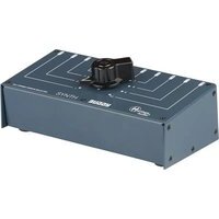
Brand : Heritage Audio
Model : MCM-8 II
Category : Audio Mixer