
NET-LOG - Media player Sonifex - Free user manual and instructions
Find the device manual for free NET-LOG Sonifex in PDF.


| Product Type | Network Audio Logger/Player |
| Brand | Sonifex |
| Model | NET-LOG |
| Dimensions (W x H x D) | 48.3 cm x 4.4 cm x 20.0 cm (1U rackmount) |
| Weight | 2.5 kg (approx.) |
| Power Supply | 100-240V AC, 50/60Hz, internal auto-ranging |
| Power Consumption | 30W (max) |
| Audio Formats Supported | MP3, WAV, AAC, FLAC, PCM (16/24-bit, up to 48 kHz) |
| Recording Capability | Scheduled and continuous recording to internal storage or network |
| Playback Features | Playlist management, cue points, loop, auto-fade |
| Network Connectivity | Ethernet 10/100/1000 Base-T, support for TCP/IP, FTP, SNTP |
| Audio Inputs/Outputs | Balanced XLR analog I/O, AES/EBU digital I/O |
| Control Interfaces | GPIO, RS-232, web interface, front panel buttons |
| Storage | Internal SSD (120 GB), expandable via USB/eSATA |
| Operating Temperature | 0°C to 40°C |
| Humidity | 10% to 90% non-condensing |
| Maintenance | Clean exterior with soft dry cloth; avoid liquids |
| Safety Precautions | Operate in well-ventilated area; do not block vents |
| Spare Parts & Repairability | Contact Sonifex support for authorized service |
| General Information | Professional-grade network audio logger for broadcast use |
Frequently Asked Questions - NET-LOG Sonifex
User questions about NET-LOG Sonifex
0 question about this device. Answer the ones you know or ask your own.
Ask a new question about this device
Download the instructions for your Media player in PDF format for free! Find your manual NET-LOG - Sonifex and take your electronic device back in hand. On this page are published all the documents necessary for the use of your device. NET-LOG by Sonifex.
USER MANUAL NET-LOG Sonifex
natural_image
Front view of a silver network equipment unit labeled 'Net-Log' with control buttons and ports (no readable text beyond branding)Manufacturers of audio & video
products for radio & TV broadcasters
SONIFEX
Net-Log Handbook
For the latest Sonifex handbook information please visit the Sonifex website at www.sonifex.co.uk
This handbook is for use with the following product:
Net-Log Audio Logger
Stock Code: 30-136
Revision 3.01 February 2020
©Sonifex Ltd, 2020
All Rights Reserved
Sonifex Ltd, 61, Station Road, Irthlingborough,
Northants, NN9 5QE, England.
Tel: +44 (0)1933 650 700
Fax: +44 (0)1933 650 726
Email: sales@sonifex.co.uk
Website: https://www.sonifex.co.uk
Information in this document is subject to change without notice and does not represent a
commitment on the part of the vendor. Sonifex Ltd shall not be liable for any loss or damage
whatsoever arising from the use of information or any error contained in this manual.
No part of this manual may be reproduced or transmitted in any form or by any means, electronic or mechanical, including photocopying, recording, information storage and retrieval systems, for any purpose other than the purchaser's personal use, without the express written permission of Sonifex Ltd. Unless otherwise noted, all names of companies, products and persons contained herein are part of a completely fictitious adaptation and are designed solely to document the use of Sonifex product.
Made in the UK by SONIFEX
Contents
Contents
Product Warranty - 2 Year Extended i
Sonifex Warranty & Liability Terms & Conditions i
-
Definitions i
-
Warranty
Unpacking Your Product ii
Repairs & Returns iii
CE Conformity iii
Safety & Installation of Mains Operated Equipment iii
Voltage Setting Checks iii
Fuse Rating iii
Power Cable & Connection iii
WEEE Directive iv
Atmosphere/Environment
- Introduction
General Overview
The Net-Log
Net-Log Control Software
Recording
Playing
Archiving
Network
Required Hardware
- Net-Log Hardware
Physical Description
Power
5
Level Indicators
Record Control/Indicator
Archive Alarm
Disk Drive Alarm
Reset Switch
Audio Inputs/Input Level Control
Network Status Indicators
Network Connections
RS232 Serial Ports
Alarm Outputs And Remote Inputs And Outputs
- Set-up & Installation
Adjusting Record Input Levels
Network Topology
iv
1
1
1
2
2
2
2
3
4
5
5
m = 311
5
6
6
6
6
7
7
7
7
7
8
8
8
Maximum Network Connections 9
Connecting Net-Log To Your Network 10
IP Addresses 10
Subnet Masks 11
Installing Net-Log-Win Software 11
Entering Network Settings 11
- Startup & Login 16
Starting Net-Log-Win 16
Maximum Concurrent Users 16
Multiple Net-Logs On A Network 16
Licensing Your Net-Log 16
Obtaining License Codes 16
The Login Procedure 17
The Device List Editor 17
First Time Use of Net-Log 18
Changing User Details 18
General Screen Layout 19
Disconnect/Log-Off Button 20
Net-Log Selector 20
Alarm Indicators 20
Network Activity Indicators 20
Net-Log & PC Time 20
Status Bar 20
Screen Selection Buttons 20
Mentor Status Indicator 20
- Recording 21
The Record Screen 21
Manual Recording 21
Program Recording 21
Auto Recording 21
Remote Recording 21
Serial Recording 21
Manual Recording 22
Program Recording 22
Saving and Loading Record Programs 23
Auto Recording 23
Remote Recording 24
Serial Recording 24
Record Tally Outputs 24
Contents
6. Playing & Downloading 25
Track List Display 25
Play Download 25
Play Program 26
Play Stream 27
Play File 28
7. Archiving 30
The Archiving Process 30
Configuring Archival To A Networked PC 30
Alarm Enabled 30
Buffer Size 31
Warn Time 31
Arrange Archive Audio into Fixed Duration Files 31
Target File Duration 31
File Type 31
Destination IP Address 31
Target Folder Share Name 31
Auto Purge on Record Stop Enabled 31
Format of Archived Files
Beginning to Archive
8. Serial Control Interface
Televic CE2500 Interface
Disabled 34
Single Mic 34
Mic Range 34
Televic CE2500 Protocol 35
System Synchronisation 36
President Microphone Activation 36
President Microphone Deactivation 36
Delegate Microphone Activation 36
Delegate Microphone Deactivation 36
Deactivate All Microphones 36
System Reset (Deactivate All Microphones) 36
AMX/Crestron Interface 37
AMX/Crestron Protocol 37
Speed of Commands & Responses: 37
Record Start Command 38
Record Stop Command 38
Status Command 38
Time Command 38
Date Command 38
Reply Error Codes 38
9. Options 39
Saving and Loading Options 39
Record Options 39
Disable 39
Override Enabled 39
Format 39
Mode 40
Channels 40
Sample Rate & Bit Rate 40
Start Level 40
Start Duration 40
Stop Level 40
Stop Duration 40
Service Names 40
Record Capacity 40
Archive Options 40
Alarm Enabled 41
Buffer Size (Mbytes) 41
Warn time prior to data loss 41
Arrange Archive Audio into Fixed Duration Files 41
Target File Duration (mins) 41
Target File Type 41
Destination IP Address 41
Target Folder Share Name 41
Auto Purge on Record Stop Enabled 41
Archive Auto Continue Enabled 41
Play Options 41
Use Defaults 42
Default Play Screen 42
Play Download Defaults: 42
Select Audio By Cut and Generate File Name From Cut Details 42
Folder 42
File Type and Bit Rate 42
Play Program Defaults: 42
Auto Create Program Name and Download Separate Cut
For Selected Days 42
Contents
Folder 42
File Type and Bit Rate 42
Play Stream Defaults: 42
Ignore cut end time selection 42
Play File Defaults: 42
Folder 42
Remotes Options 42
Disabled 43
Momentary 43
Latching 43
Normally Off, Switched On For Alarm Condition 43
Clock Source Options 43
Control Options 44
No Control/Interface Selected 44
Televic CE2500 44
AMX/Crestron 44
Net-Log-Win Options 44
Info Font 45
User Font 45
Information
10.The Administrator
Licenses 46
Accounts Editor 46
"admin" 46
"user1" to "user25" 46
"guest" 46
Function Access – View 47
Function Access – Control 47
User Name & Password 47
The Onboard Clock 48
Updating The Onboard Clock 48
Network Settings 48
Updating Firmware 49
Resetting The Net-Log 50
- Tools 51
Show Cut List 51
Auto Refresh Cut Display 51
Play Cut Auto Load 51
Hide Unavailable Cuts 51
Suspend Play Programs 51
Log Play Program Operation 51
Deleting Cuts 51
View 51
Net-Log Connections 51
Net-Log Status 52
Drive Alarm 52
Cut Change 52
Program Change 52
Config Change 52
Record Auto Enabled 52
Record Active 52
Archive Enabled 52
Archive Pending 52
Archive Auto Purge 52
Archive Active 52
Archive Warn 52
Archive Alarm 52
Network Stats 53
Audio Header Info 53
Play Program Log 54
About Sonifex Net-Log 54
12.Auto-Archive 55
Introduction 55
Licensing 55
The Net-Log List 55
The Status Bar 55
Performance 56
System Set-up 56
Starting The Archive 56
The Settings Screen 56
Device List 56
System Name 57
Force Record Stop at Midnight 58
Auto-Delete Archives 58
Use mm-dd-yyyy Format for Archive Folders 58
E-Mail 58
The Status Screen 58
The Control Screen 59
Contents
The Archive Screen 59
The Event Log Screen 60
Reports
Status Report 60
Error Report 61
Possible Errors 61
Archive Warn Report 61
Archive Alarm Report 61
Startup/ Shutdown 61
The Schedule 61
The Schedule Database 61
Network Scheduling 61
The Schedule Screen 62
13.Net-Log Scheduler 64
Introduction 64
Database Connection Status 64
Primary and Backup Schedules 64
Database Locations 65
Create a New Event 66
Refreshing the Schedules 67
14.Technical Specification
MP2 Record Data Rates 69
MP3 Data Rates Supported For Play Download 69
Pin Connections 69
15.Glossary 72
Figures
Fig 1-1: Net-Log System Block Diagram 1
Fig 1-2: Single Net-Log Connection example 2
Fig 1-3: Multiple Net-Log Connection example 3
Fig 2-1: The Front Panel 5
Fig 2-2: The Rear Panel 6
Fig 3-1: Network Topology 8
Fig 3-2: Maximum Simultaneous Streams. 9
Fig 3-3: IP Addresses 10
Fig 3-4 : Net-Log-Win Installation 11
Fig 3-5: Net-Log-Win Serial Utility 12
Fig 3-6: Detail of Net-Log-Win Serial Utility 12
Fig 3-7: Diagram of a Null Modem Cable 13
Fig 3-8: Diagram of 'straight through' and 'crossover' CATS cables 13
Fig 3-9: Details of Net-Util Tool buttons 14
Fig 4-1: The Initialisation Screen 16
Fig 4-2: The Licensing Screen 17
Fig 4-3: The Login Screen 17
Fig 4-4: The Net-Log Device List Editor 18
Fig 4-5: User Details 19
Fig 4-6 General Screen Layout 20
Fig 5-1: Manual Record Screen 21
Fig 5-2: Program Record Screen 22
Fig 5-3: Program Record Popup Menu Commands 23
Fig 5-4: Auto Record Mode 24
Fig 6-1: Play Download Screen 25
Fig 6-2: Play Program Screen 26
Fig 6-3: Play Stream Screen 28
Fig 6-4: Minimum Play Stream Delays 28
Fig 6-5: Play File Screen 29
Figures
Fig 7-1: Archive Options Screen 30
Fig 7-2: Archive Screen. 32
Fig 8-1: Control Options Screen 33
Fig 8-2: Televic CE2500 Interface Options 34
Fig 9-1: Record Options 39
Fig 9-2: Archive Options 41
Fig 9-3: Play Options 42
Fig 9-4: Record Remotes Options 43
Fig 9-5: Clock Source Options 43
Fig 9-6: Control Interface Options 44
Fig 9-7: Televic CE2500 Control Options 44
Fig 9-8: Net-Log-Win Options 45
Fig 9-9: Info Options 45
Fig 10-1: Net-Log Administrator Menu 46
Fig 10-2: Accounts Editor 46
Fig 10-3: Function View 47
Fig 10-4: Function Control 47
Fig 10-5: Select or Edit User Name & Password 47
Fig 10-6: Network Settings 49
Fig 10-7: Upgrading Firmware 49
Fig 11-1: Net-Log Tools Menu. 51
Fig 11-2: Net-Log Connections Screen 52
Fig 11-3: Net-Log Status Screen 53
Fig 11-4: Net-Log Stats Screen 53
Fig 11-5: Net-Log Audio Header Info Screen 53
Fig 11-6: Play Program Log Screen 54
Fig 11-7: Net-Log About Screen 54
Fig 12-1: The Status Screen 55
Fig 12-2: The Net-Log List 55
Fig 12-3: Net-Log Device List 57
Fig 12-4: The Settings Screen 57
Fig 12-5: The Settings Screen 58
Fig 12-6: The Status Screen 59
Fig 12-7: The Control Screen 59
Fig 12-8: The Archive Screen 60
Fig 12-9: The Event Log Screen 60
Fig 12-10: Sharing and Security Selection 62
Fig 12-11: Schedule Properties Screen 62
Fig 12-12: Permissions Screen 62
Fig 12-13: D:Scribe Dongle 62
Fig 12-14: Primary Archive Screen 63
Fig 13-1: Net-Log Scheduler's Listing 64
Fig 13-2: Block diagram showing two mirrored systems for use as primary and backup 65
Fig 13-3: Selecting Database Locations 65
Fig 13-4: Entering a New Schedule Recording 66
Fig 13-5: Updated Listings with a New Recording 66
Fig 13-6: A Schedule List Showing Multiple Recordings 67
Warranty Registration
SONIFEX
Register Online for an Extended 2 Year Warranty
As standard, Sonifex products are supplied with a 1 year back to base warranty.
If you register the product online, you can increase your product warranty to 2 years and we can also keep you informed of any product design improvements or modifications.
Product: ____ Serial No: ____
To register your product, please go online to www.sonifex.co.uk/register
Product Warranty - 2 Year Extended
As standard, Sonifex products are supplied with a 1 year back to base warranty. In order to register the date of purchase and so that we can keep you informed of any product design improvements or modifications, it is important to complete the warranty registration online. Additionally, if you register the product on the Sonifex website, you can increase your product warranty to 2 years. Go to the Sonifex website at: http://www.sonifex.co.uk/technical/register/index.asp to apply for your 2 year warranty.
Note: For your own records the product serial number is recorded on the CE certification page of this handbook.
Sonifex Warranty & Liability Terms & Conditions
1. Definitions
'the Company' means Sonifex Ltd and where relevant includes companies within the same group of companies as Sonifex Limited.
'the Goods' means the goods or any part thereof supplied by the Company and where relevant includes: work carried out by the Company on items supplied by the Purchaser; services supplied by the Company; and software supplied by the Company.
'the Purchaser' means the person or organisation who buys or has agreed to buy the Goods.
'the Price' means the Price of the Goods and any other charges incurred by the Company in the supply of the Goods.
'the Warranty Term' is the length of the product warranty which is usually 12 months from the date of despatch; except when the product has been registered at the Sonifex website when the Warranty Term is 24 months from the date of despatch.
'the Contract' means the quotation, these Conditions of Sale and any other document incorporated in a contract between the Company and the Purchaser.
This is the entire Contract between the parties relating to the subject matter hereof and may not be changed or terminated except in writing in accordance with the provisions of this Contract. A reference to the consent, acknowledgement, authority or agreement of the Company means in writing and only by a director of the Company.
2. Warranty
a. The Company agrees to repair or (at its discretion) replace Goods which are found to be defective (fair wear and tear excepted) and which are returned to the Company within the Warranty Term provided that each of the following are satisfied:
i. notification of any defect is given to the Company immediately upon its becoming apparent to the Purchaser;
ii. the Goods have only been operated under normal operating conditions and have only been subject to normal use (and in particular the Goods must have been correctly connected and must not have been subject to high voltage or to ionising radiation and must not have been used contrary to the Company's technical recommendations);
iii. the Goods are returned to the Company's premises at the Purchaser's expense;
iv. any Goods or parts of Goods replaced shall become the property of the Company;
v. no work whatsoever (other than normal and proper maintenance) has been carried out to the Goods or any part of the Goods without the Company's prior written consent;
Warranty
vi. the defect has not arisen from a design made, furnished or specified by the Purchaser;
vii. the Goods have been assembled or incorporated into other goods only in accordance with any instructions issued by the Company;
viii. the defect has not arisen from a design modified by the Purchaser;
ix. the defect has not arisen from an item manufactured by a person other than the Company. In respect of any item manufactured by a person other than the Company, the Purchaser shall only be entitled to the benefit of any warranty or guarantee provided by such manufacturer to the Company.
b. In respect of computer software supplied by the Company the Company does not warrant that the use of the software will be uninterrupted or error free.
c. The Company accepts liability:
(i) for death or personal injury to the extent that it results from the negligence of the Company, its employees (whilst in the course of their employment) or its agents (in the course of the agency);
(ii) for any breach by the Company of any statutory undertaking as to title, quiet possession and freedom from encumbrance.
d. Subject to conditions (a) and (c) from the time of despatch of the Goods from the Company's premises the Purchaser shall be responsible for any defect in the Goods or loss, damage, nuisance or interference whatsoever consequential economic or otherwise or wastage of material resulting from or caused by or to the Goods. In particular the Company shall not be liable for any loss of profits or other economic losses. The Company accordingly excludes all liability for the same.
e. At the request and expense of the Purchaser the Company will test the Goods to ascertain performance levels and provide a report of the results of that test. The report will be accurate at the time of the test, to the best of the belief and knowledge of the Company, and the Company accepts no liability in respect of its accuracy beyond that set out in Condition (a).
f. Subject to Condition (e) no representation, condition, warranty or other term, express or implied (by statute or otherwise) is given by the Company that the Goods are of any particular quality or standard or will enable the Purchaser to attain any particular performance or result, or will be suitable for any particular purpose or use under specific conditions or will provide any particular capacity, notwithstanding that the requirement for such performance, result or capacity or that such particular purpose or conditions may have been known (or ought to have been known) to the Company, its employees or agents.
g. (i) To the extent that the Company is held legally liable to the Purchaser for any single breach of contract, tort, representation or other act or default, the Company's liability for the same shall not exceed the price of the Goods.
(ii) The restriction of liability in Condition (g)(i) shall not apply to any liability accepted by the Seller in Condition (c).
h. Where the Goods are sold under a consumer transaction (as defined by the Consumer Transactions (Restrictions on Statements) Order 1976) the statutory rights of the Purchaser are not affected by these Conditions of Sale.
Unpacking Your Product
Each product is shipped in protective packaging and should be inspected for damage before use. If there is any transit damage take pictures of the product packaging and notify the carrier immediately with all the relevant
details of the shipment. Packing materials should be kept for inspection and also for if the product needs to be returned.
The product is shipped with the following equipment so please check to ensure that you have all of the items below. If anything is missing, please contact the supplier of your equipment immediately.
Item
Quantity
Product unit 1
IEC mains lead fitted with moulded mains plug 1
Handbook and warranty card 1
If you require a different power lead, please let us know when ordering the product.
Repairs & Returns
Please contact Sonifex or your supplier if you have any problems with your Sonifex product. Email technical.support@sonifex.co.uk for the repair/ upgrade/returns procedure, or for support & questions regarding the product operation.
CE Conformity
The products in this manual comply with the essential requirements of the relevant European health, safety and environmental protection legislation.
The technical justification file for this product is available at Sonifex Ltd.
The declaration of conformity can be found at: https://www.sonifex.co.uk/declarations
Safety & Installation of Mains Operated Equipment
There are no user serviceable parts inside the equipment. If you should ever need to look inside the unit, always disconnect the mains supply before removing the equipment covers. The cover is connected to earth by means of the fixing screws. It is essential to maintain this earth/ground connection to ensure a safe operating environment and provide electromagnetic shielding.
Voltage Setting Checks
Ensure that the machine operating voltage is correct for your mains power supply by checking the box in which your product was supplied. The voltage is shown on the box label. The available voltage settings are 115V, or 230V. Please note that all products are either switchable between 115V and 230V, or have a universal power supply.
Fuse Rating
The product is supplied with a single fuse in the live conducting path of the mains power input. For reasons of safety it is important that the correct rating and type of fuse is used. Incorrectly rated fuses could present a possible fire hazard, under equipment fault conditions. The active fuse is fitted on the outside rear panel of the unit.
Power Cable & Connection
An IEC power connector is supplied with the product which has a moulded plug attached.
The mains plug or IEC power connector is used as the disconnect device. The mains plug and IEC power connector shall remain readily operable to disconnect the apparatus in case of a fault or emergency.
The mains lead is automatically configured for the country that the product is being sent to, from one of:
Safety & Installation
Territory Voltage IEC Lead Type Image
| UK & Middle East 230V UK 3 pin to IEC lead | ||
| Europe 230V | European Schuko round 2 pin to IEC lead | |
| USA, Canada and South America | 115V 3 flat pin to IEC lead | |
| Australia & New Zealand | 230V Australasian 3 flat pin to IEC lead | |
Connect the equipment in accordance with the connection details and before applying power to the unit, check that the machine has the correct operating voltage for your mains power supply.
This apparatus is of a class I construction. It must be connected to a mains socket outlet with a protective earthing connection.
Important note: If there is an earth/ground terminal on the rear panel of the product then it must be connected to Earth.
WEEE Directive

The Waste Electrical and Electronic Equipment (WEEE) Directive was agreed on 13 February 2003, along with the related Directive 2002/95/EC on Restrictions of the use of certain Hazardous Substances in electrical and electronic
equipment (RoHS). The Waste Electrical and Electronic Equipment Directive (WEEE) aims to minimise the impacts of electrical and electronic equipment on the environment during their life times and when they become waste.
All products manufactured by Sonifex Ltd have the WEEE directive label placed on the case. Sonifex Ltd will be happy to give you information about local organisations that can reprocess the product when it reaches its “end of use”, or alternatively all products that have reached “end of use” can be returned to Sonifex and will be reprocessed correctly free of charge.
Atmosphere/Environment
This apparatus should be installed in an area that is not subject to excessive temperature variation (<0°C, >50°C), moisture, dust or vibration.
This apparatus shall not be exposed to dripping or splashing, and no objects filled with water, such as vases shall be placed on the apparatus.
1. Introduction
General Overview
The principal behind the Net-Log logger is that generally speaking, computers should not be used for recording audio where their general unreliability can cause system crashes or lockups, with little regard for the security of the audio being recorded. However, for playback, using computers is perfectly acceptable and probably preferable, due to the ability to manipulate and edit the audio, provided it is in a suitable format.
The Net-Log
The Net-Log is a 1U rack-mount, hardware audio recorder, designed primarily for audio logging in a broadcast environment. It is able to record up to 4 mono, or 2 stereo audio feeds, which are saved onto a large internal IDE hard disk. The hard disk is continuously over-written, allowing access to all the audio recorded on it. Apart from the front panel mounted record override button, all functions and configurations are controlled via the Ethernet TCP/IP network connection using the supplied Windows control software package.
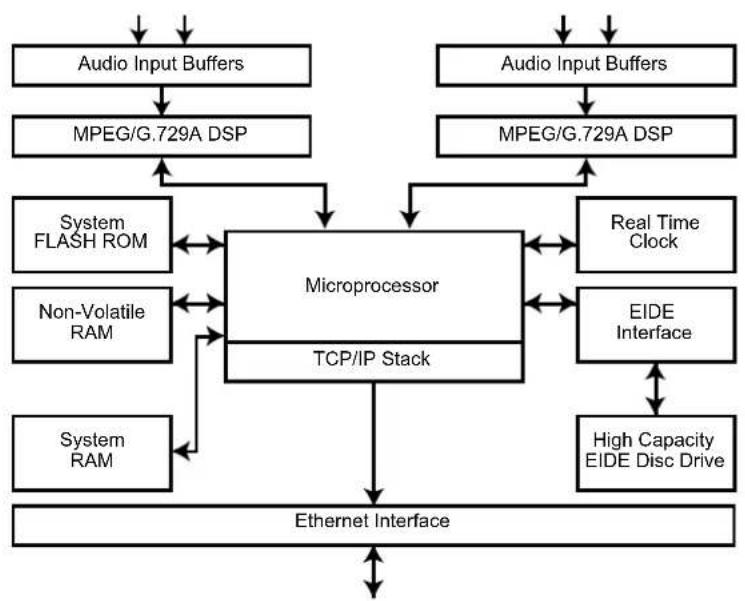
flowchart
graph TD
    A["Audio Input Buffers"] --> B["MPEG/G.729A DSP"]
    C["Audio Input Buffers"] --> D["MPEG/G.729A DSP"]
    B --> E["Microprocessor"]
    D --> E
    E --> F["TCP/IP Stack"]
    E --> G["Real Time Clock"]
    E --> H["EIDE Interface"]
    E --> I["High Capacity EIDE Disc Drive"]
    E --> J["Ethernet Interface"]
    K["System FLASH ROM"] <--> E
    L["Non-Volatile RAM"] <--> E
    M["System RAM"] <--> E
    N["System"] <--> E
Fig 1-1: Net-Log System Block Diagram
1 Introduction
Net-Logs can be used singularly (Fig 1-2), or if more record channels are required, multiple Net-Logs can easily be configured to operate on the same Network (Fig 1-3).
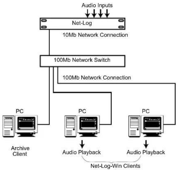
flowchart
graph TD
    A["Audio Inputs"] --> B["Net-Log"]
    B --> C["10Mb Network Connection"]
    B --> D["100Mb Network Switch"]
    D --> E["100Mb Network Connection"]
    E --> F["PC"]
    E --> G["PC"]
    E --> H["PC"]
    F --> I["Archive Client"]
    G --> J["Audio Playback"]
    H --> K["Audio Playback"]
    L["Net-Log-Win Clients"] --> M["PC"]
Fig 1-2: Single Net-Log Connection example
Net-Log Control Software
Net-Log works in conjunction with a software control package that runs under Windows. This package consists of Net-Log-Win, Net-Util and Net-Log Auto-Archive. Net-Log-Win is the main control and configuration program. Net-Util is a configuration and monitoring utility that communicates with Net-Log via a serial connection. Net-Log Auto-Archive is a program designed to Archive audio data from multiple Net-Logs simultaneously.
Recording
Audio presented to the inputs is encoded in one of two user selectable formats, MPEG layer 2 or G.729A (An additional license is required to enable the G.729A format – contact Sonifex Ltd for details). The compressed data is then written to the internal IDE hard disk drive. Recording can be either continuous or programmed to start and stop at selected times. Record set-up allows for mono/dual mono/stereo and sample-frequency/bit-rate selection, depending on record format selected.
When recording has started, these parameters can only be altered once the audio on the disk has been deleted. The hard disk audio cannot be deleted whilst the logger is recording.
Playing
Two methods of audio playback are supported by Net-Log in conjunction with the Net-Log-Win software. Sections of audio can be transferred to a file on the PC using the Play Download function. These files can then be played using Net-Log-Win's media file player. Alternatively, Play Stream offers the ability to play audio direct from the Net-Log.
Archiving
Archive is an automated method of transferring audio data from one or more Net-Logs to a designated PC via the Network interface. When the audio data arrives at the PC, it can be arranged into files of a predetermined size. These files can then be copied to a removable media for long-term storage. If temporary audio storage is required, to satisfy broadcast authority requirements for example, then Archiving may not be necessary as the large hard drives used in Net-Log can, depending on the format or bit rate of the recordings, hold several weeks of audio. Sections of the audio could be downloaded as required using the Play Download function. The Net-Log-Win software provides a simple method of Archiving audio data for users with a single Net-Log. For larger installations where multiple Net-Logs
are used, the Net-Log Auto-Archive package offers the ability to archive audio data from up to 20 Net-Logs simultaneously.
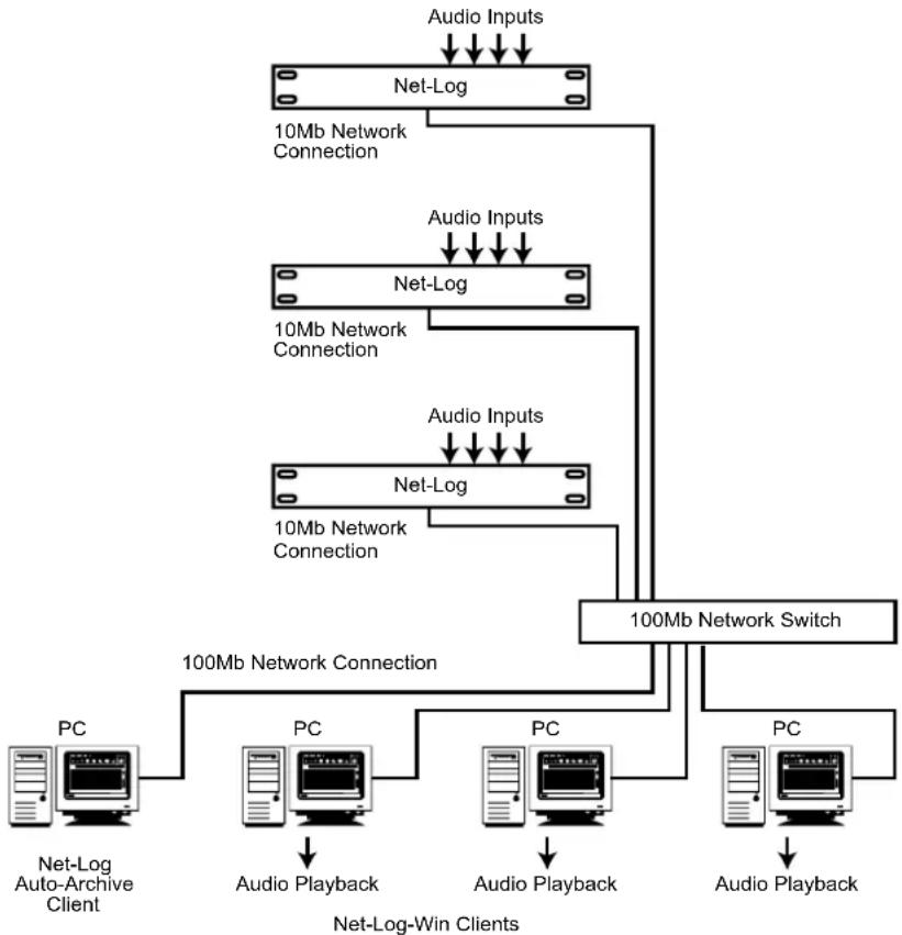
flowchart
graph TD
    A["Audio Inputs"] --> B["Net-Log"]
    B --> C["10Mb Network Connection"]
    C --> D["Net-Log"]
    D --> E["10Mb Network Connection"]
    E --> F["Net-Log"]
    F --> G["10Mb Network Connection"]
    G --> H["100Mb Network Switch"]
    H --> I["PC"]
    I --> J["Net-Log Auto-Archive Client"]
    I --> K["PC"]
    K --> L["Audio Playback"]
    K --> M["PC"]
    M --> N["Audio Playback"]
    M --> O["PC"]
    O --> P["Audio Playback"]
    style A fill:#f9f,stroke:#333
    style H fill:#ccf,stroke:#333
Fig 1-3: Multiple Net-Log Connection example
Network
The speed of the network connection on Net-Log is 10Mbps, and the physical connection is made via a BNC connector for coax cables, or a RJ45 connector for twisted pair cabled networks. For maximum network performance, the Net-Logs and client PCs' should be linked via a network Switch. This will cater for the Net-Logs' 10Mb connection whilst allowing the client PCs' to run at 100MB/1GB. In most applications, this arrangement will provide sufficient network performance for multiple clients to simultaneously access multiple Net-Logs. However, on existing networks where network traffic is already high, or where archiving audio from multiple Net-Logs running at high data rates, the required bandwidth of the network hardware needs to be carefully considered. In such cases a dedicated network may be required. The specification of the PC used as the Auto-Archive client will also need to be able to handle the large amounts of audio data being transferred. If the network hardware is incapable of handling the required data rates, Play Stream will be interrupted by periods of silence and audio data on the Net-Log may be overwritten before it can be archived to the target PC.
The following example illustrates a known working configuration and provides a starting point when considering larger systems.
5 Net-Logs each configured as follows:
4 mono channels of MPEG compression recording non-stop, 32 kHz sample rate, 192 kbps bit rate, archiving to a single Auto-Archive client PC via a dedicated
1 Introduction
10/100Mb Network switch. The Auto-Archive client PC is an Intel PIII, 1GHz or equivalent fitted with a 100Mb network card.
This system provides sufficient bandwidth for continuous archiving plus the capability for additional Net-Log-Win clients to Play Stream audio.
Required Hardware
Audio can be delivered to a network-connected remote PC for live playback through an appropriate audio card. For recordings made using the MPEG format, a software codec supplied as part of the Windows XP, 7, 8 or 10 operating system, provides the decoding and conversion of the audio to a format supported by any standard Windows audio card capable of playing .wav files. Likewise, recordings made using G.729A are converted to the same Windows supported format by a software codec embedded in the Net-Log-Win software. Therefore, Net-Log-Win client PC's can play audio in both formats using a single audio card.
It is recommended to use a PC with the following minimum specification:
Pentium 166MHz
64MB RAM
Audio card & speakers as above
100Mbps network connection
Windows 7, 8 or 10
DirectX 6 or greater
2. Net-Log Hardware
Physical Description
The logger is housed in a 1U high 19" rack mount box. The front panel is chrome plated and there are chrome plated panel inserts for the fan inlet/outlet with domed labels for the "Sonifex" and "Net-Log".
Power
The unit is powered via an IEC filtered input for 95 – 265V supply at 47–63Hz, peak 60W, 30W average. There is an external fuse for the mains input that is rated at 2A. We recommend that the Net-Log is operated from an uninterruptible power supply. It should be noted that the record header is written regularly during the record process so if the power fails the data lost will be limited. At a bit rate of 192kbps this loss will be a maximum of 1 minute. Lower data rates will give proportionately greater time loss.
Level Indicators
There are four tri-colour LED's positioned on the front panel indicating input levels for each individual channel:
| Led State Meaning |
| Off Input level < -18dBu |
| Yellow -18dBu < Input level < 0dBu |
| Green 0dBu < Input level < 12dBu |
| Red Input level >12dBu |
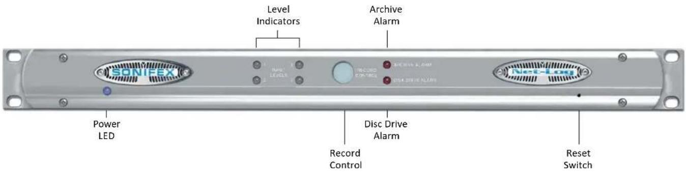
Fig 2-1: The Front Panel
2 Net-Log Hardware
Record Control/Indicator
This backlit button gives an indication of what channels are currently being recorded and can also be used to give limited control over the recording. When pressed, the button will flash indicating that a record start or stop has been initiated and must be pressed again within three seconds to confirm the action. The LED states and their relative modes are shown below:-
| Button State Mode |
| Off No channels recording |
| Fast flashing Record Start/Stop initiated |
| Slow flashing Some channels recording |
| On All available channels recording |
When the button is pressed, the Net-Log checks to see which channels can be altered using this button (See Options, Record Format options, Override Enabled). If recording, a confirmed button press will stop the recording. If not recording, a confirmed button press will start the recording on enabled channels.
Archive Alarm
This red coloured LED is used to warn of loss of data during a recording process. If the Net-Log is about to overwrite data that has not been archived on to a remote computer then this indicator will start to flash. The amount of warning time you get before data is lost can be configured in the main software.
| Led State Meaning | |
| Off Normal | |
| Flashing Data is about to be lost | |
| On Data has been lost | |
Disk Drive Alarm
A red coloured LED giving an indication that there has been an error reading/writing from/to the internal hard disk.
Reset Switch
Restarts the machine. NOTE that this does not overwrite any configurations and simply reboots the machine.
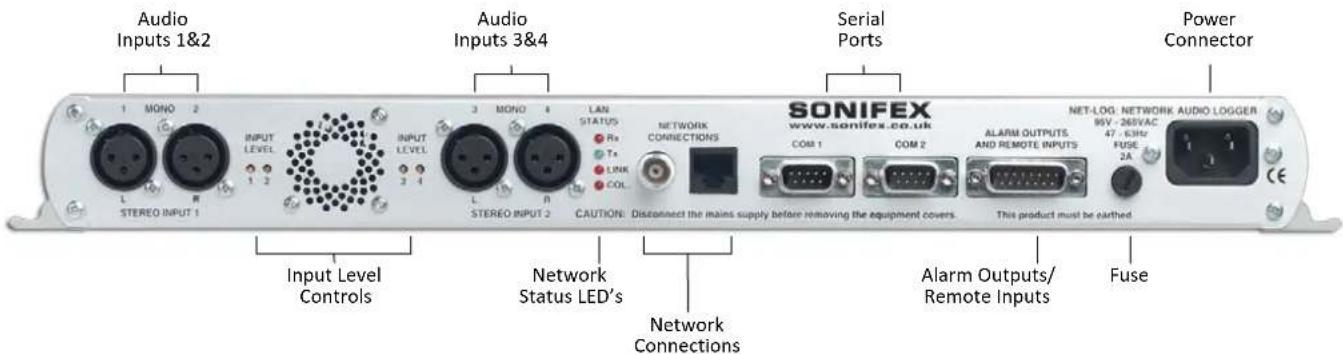
Fig 2-2: The Rear Panel
Audio Inputs/Input Level Control
The audio inputs consist of four 3-pin XLR connectors (2-channel stereo, 4-channel mono) with independent level gain controls for each input, accessible through the rear-panel using a flat-blade screwdriver.
Network Status Indicators
There are four network status indicators, which are all labelled independently.
| Rx Receiving data | |
| Tx Transmitting data | |
| Link A network link has been established | |
| Col Network collision | |
Network Connections
There are two network connectors: one a BNC (coax, 10base2), and the other an RJ45 (10baseT). Either of these can be used for TCP/IP connection.
RS232 Serial Ports
There are two 9 pin D-Type connectors (COM1 and COM2) situated on the rear panel. COM1 is used for firmware updates and for updating the network settings, i.e. IP Address, Subnet Mask, etc. It can also be used as a messaging output for data analysis. COM2 is used for the Serial Control Interface.
The settings for COM1 are fixed at:-
| Baud rate 115200 | |
| Data Bits 8 | |
| Parity NONE | |
| Stop Bits 1 |
Alarm Outputs And Remote Inputs And Outputs
The remote connector is a 15 pin male D-type, which has four remote inputs to control recording, four record tally outputs to indicate which channels are recording and a double-pole-double-throw alarm output relay which activates on either the Archive Alarm or the Hard-Disk Alarm.
The remote inputs and output can be driven by 5V logic. The inputs are active low. These can be set to momentary or latching action via the Remote Options screen. The record tally outputs are open-collector driven. See Chapter 14 for pin connection details.
3 Set-up & Installation
3. Set-up & Installation
Adjusting Record Input Levels
The peak audio input levels are preset at +12dBu. This means that an audio signal of +12dBu, once encoded, will be at the maximum digital value. To change the peak audio input level, follow the procedure below.
- Switch the unit on and while the alarm LED's on the front panel are flashing, press the record control button. The record button will illuminate.
- Connect a constant audio signal at the required peak level to Input 1.
-
Adjust the Input 1 level control on the rear panel until the input level LED 1 on the front panel is green.
-
Repeat steps 2 & 3 for all 4 inputs. When you have finished, simply press the record control button and the Net-Log will complete its initialisation procedure.
The peak audio input levels can be changed at any time, but it should be noted that any ongoing recordings would be interrupted as the unit has to be power reset.
Network Topology
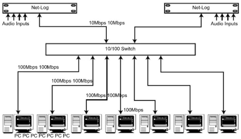
The network that the Net-Log is connected to must be a dedicated network, if you are to guarantee the audio being available for play streaming. The ideal configuration is shown in Fig 3-1, with the Net-Log(s) connected directly to a network switch, which is connected directly to dedicated network interface cards in the PC's. It is under these conditions that the test results have been achieved in Fig 3-2.
flowchart
graph TD
    A["Net-Log"] -->|Audio Inputs| B["10/100 Switch"]
    C["Net-Log"] -->|Audio Inputs| B
    B --> D["PC PC PC PC PC PC PC"]
    B --> E["PC PC PC PC PC PC"]
    B --> F["PC PC PC PC PC PC"]
    B --> G["PC PC PC PC PC PC"]
    B --> H["PC PC PC PC PC PC"]
    B --> I["PC PC PC PC PC PC"]
    B --> J["PC PC PC PC PC PC"]
    B --> K["PC PC PC PC PC PC"]
    B --> L["PC PC PC PC PC PC"]
    B --> M["PC PC PC PC PC PC"]
    B --> N["PC PC PC PC PC PC"]
    B --> O["PC PC PC PC PC PC"]
    B --> P["PC PC PC PC PC PC"]
    B --> Q["PC PC PC PC PC PC"]
    B --> R["PC PC PC PC PC PC"]
    B --> S["PC PC PC PC PC PC"]
    B --> T["PC PC PC PC PC PC"]
    B --> U["PC PC PC PC PC PC"]
    B --> V["PC PC PC PC PC PC"]
    B --> W["PC PC PC PC PC PC"]
    B --> X["PC PC PC PC PC PC"]
    B --> Y["PC PC PC PC PC PC"]
    B --> Z["PC PC PC PC PC PC"]
    B --> AA["PC PC PC PC PC"]
    B --> AB["PC PC PC PC PC"]
    B --> AC["PC PC PC PC PC"]
    B --> AD["PC PC PC PC PC"]
    B --> AE["PC PC PC PC PC"]
    B --> AF["PC PC PC PC PC"]
    B --> AG["PC PC PC PC"]
Fig 3-1: Network Topology
Maximum Network Connections
The maximum number of people that can connect to the Net-Log and use Play Streaming simultaneously is dependent on the number of software licenses that have been bought and also the data rate of the recordings that you are making. The software license is available as either a 2-stream license, or a 5-stream license. Due to the low fixed bit rate of the G.729A record format, the type of license (2 or 5 streams) is the only limiting factor for the number of simultaneous Play Streams when G.729A is selected.
| MPEG Record Bit Rate | Maximum number of simultaneous streams | Total stream rate |
| 160 kbps 5 streams 800 kbps | ||
| 192 kbps 4 streams 768 kbps | ||
| 224 kbps 4 streams 896 kbps | ||
| 256 kbps 3 streams 768 kbps | ||
| 320 kbps 2 streams 640 kbps | ||
| 384 kbps 2 streams 768 kbps |
Fig 3-2: Maximum Simultaneous Streams.
Fig 3-2 shows the maximum number of streams, for the MPEG record format, for the given recording bit rate configured. These figures assume that there is no other activity on the network, including Archiving of Net-Log audio. The figures show that for 5 people to be able to simultaneously Play Stream one stereo channel of MPEG audio, the recording bit-rate must be set to 160kbps or less.
If you have two pairs of stereo channels on a Net-Log set at different bit-rates, the total number of people that can Play stream them is governed by the combined bit rates of the play streaming. The limit of the maximum total stream rate is around 900kbps.
Above this stream rate, play streaming will start to fail, i.e. there will be non-continuous audio and audio silences on playback.
E.g. 2 people play streaming 64kbps recording
$$ = 2 \times 6 4 k b p s = 1 2 8 k b p s, \text { plus } $$
2 people play streaming 384kbps recording
$$ = 2 \times 3 8 4 k b p s = 7 6 8 k b p s $$
Total = 896kbps, which is less than 900kbps and allowable.
Play streaming can occur with archiving also happening in the background. Archiving audio to a nominated hard-drive on the network happens at a maximum data rate of 1000kbps. This data rate falls if play streaming is occurring, because play streaming is given a priority over any other process. There is a downside of this priority, which is that if many people are play streaming continuously for a number of hours (or days), the archiving data rate may fall below the recording data rate, so that the audio is not being archived as quickly as it is recorded.
You can calculate whether this will happen by subtracting the total maximum stream rate (calculated in the above example) from 1000kbps. If the remainder is less than the recording bit rate that you are archiving, then your archiving may happen at less than real time and will, eventually fail. Note: this does assume that the play streaming is at, or beyond, the maximum for a considerable length of time (to fill the Net-Log hard disk). Invariably, the play streaming is for "dip-in" access of a short duration (<1 hour) and the archive process has time to catch-up when there is no, or little, play streaming.
3 Set-up & Installation
Connecting Net-Log To Your Network
Before connecting the Net-Log you first need to give it an IP Address, Subnet Mask and a Default Gateway. You may need to obtain these from your network administrator, but please note that the Net-Log is not compatible with DHCP (Dynamic Host Configuration Protocol) and DNS (Domain Name System).
To help in your selection of an IP Address for the Net-Log, following is a brief description of how IP Addresses and Subnet Masks work.
IP Addresses
An IP Address is used to determine where a node (PC, Printer etc.) is situated on a network. This address must be unique to the network, otherwise conflicts will occur. The actual address is made up of 32 bits, split into four sections (each section is called an octet). Held in the address is a network ID and host ID.
The network ID, or network address, is basically the address of the local network, and all nodes within that network must have the same network ID. The host ID part of the address identifies the node within that network.
There are three different classes of IP Address: A, B and C. These determine what parts of the address contain the network ID and the host ID, (Fig 3-3).
IP Addresses
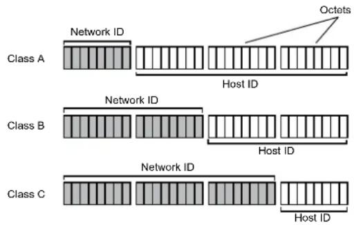
Class A example: 126.100.1.1
Class B example: 190.100.1.1
Class C example: 222.100.1.1
g 3-3: IP Addresses
Class A address: The first octet contains the network ID and the second, third and fourth contain the host ID.
Class B address: The first and second octets contain the network ID and the third and fourth contain the host ID.
Class C address: The first, second and third octets contain the network ID and the fourth contains the host ID.
So, the network ID of the IP Address that you give the Net-Log must match the network address of the network on which you connect it and the host ID of the Net-Log's IP Address must be different to that of any other device on the network.
Subnet Masks
To determine which parts of an address contain the network ID and host ID we use a Subnet Mask, which has an identical format to the IP Address being made up of 32-bits, split up into four octets. It is configured as follows:
For every bit in the IP Address that contains the network ID the corresponding bit in the Subnet Mask must be set to binary 1, (i.e. the byte of 8 bits is set to "255"). For example if the IP Address is a class A address, the network ID is contained in the first octet. So the first eight bits of the address contain the Network ID. Therefore the first eight bits in the Subnet Mask must be set to binary 1, making it "255.0.0.0".
Installing Net-Log-Win Software
The procedure below describes how to install the PC software. As the initial set-up procedure will require the use of the Net-Log Serial Utility, the software must initially be installed on a PC with a free serial port.
- Insert the Sonifex Software Installation CD into your CD-ROM drive.
- The installation process should begin automatically. If it fails to start, select "Run..." from the Start Menu and type "x:\Index.htm" where x is the letter of your CD-ROM drive.
- The installation starts by displaying a web page that has links to several software packages from Sonifex. Locate Net-Log-Win from the list and click on the link provided. The Net-Log-Win installation will begin as shown in Fig 3-4. Simply follow the on screen instructions to proceed. During the installation, Set-up will attempt to detect what version, if any, of DirectX is installed.
DirectX is required for audio playback and Net-Log-Win requires that version 6 or later is installed. If a compatible version is not found, then the supplied DirectX 8.0 will be automatically installed.
- The installation will place three shortcuts in the start menu – Net-Log-Win, Net-Util and Net-Log Auto-Archive.
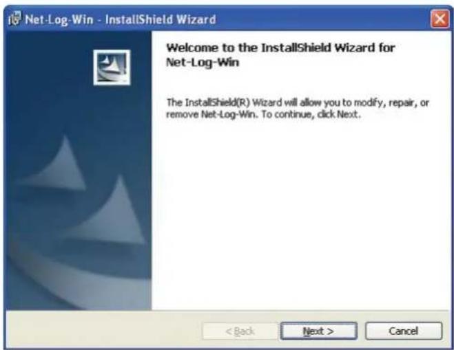
Fig 3-4 : Net-Log-Win Installation
Entering Network Settings
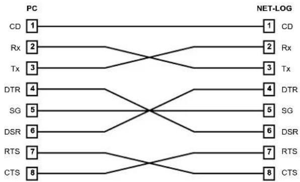
To do this you need to start the Net-Log-Win Serial Utility (Fig 3-5 & 3-6), and connect one of your PC's available serial ports to the Net-Log's serial port (COM1). This is done with the null modem cable supplied with the Net-Log.
3 Set-up & Installation
![Simulator Net Log Wire Serial Utility V1.500 File Edit View Help Network Settings MAC Address: 00/08/C2/05/41 SE IP Address: 192.168.0179 Submit Host: 293.293.2953 Default Subgroup: 192.168.038 Information of Network System complete including archive projects... archive 1 portion valid archive 2 portion valid archive 3 portion valid archive 4 portion valid including message node message node set to minimum Record 1 shared record 10 Record 2 shared record 10 Record 3 shared record 10 Record 4 shared record 10 10/08/08/27:51:40 final-up installation complete 10/08/08/27:51 License check linked [License 3], spine DeB8, on 1 COSI open Not using serial data](/content/2026/05/835038/images/d23cbcd6b4fc730526d296c779da3e316bddd81afefbb70dc5cc7b60a87abd7c.jpg)
Fig 3-5: Net-Log-Win Serial Utility
Select the relevant PC COM port number in the serial utility by using the up/down buttons (labelled "1" in Fig 3-6). Now press the Connect button (labelled "2"). To test the connection between the PC and Net-Log press the question mark Test button (labelled "3"). This sends a command to the Net-Log, and waits for a reply. If there is no reply, an error message box appears declaring that the connection test has failed.
If this occurs make sure that you have the Net-Log switched on, that all cables are correctly wired and connected, and that you have selected the correct COM port number.
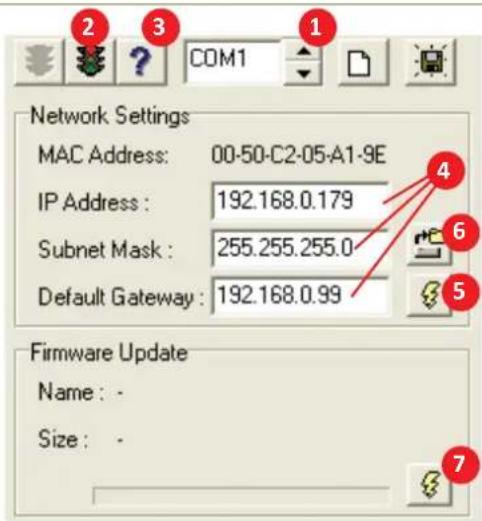
Fig 3-6: Detail of Net-Log-Win Serial Utility
The wiring for the cable is shown in Fig 3-7. If the connection is successful a message box is displayed indicating this.
Now you need to enter the IP Address, Subnet Mask and Default Gateway (labelled "4").
The Default Gateway is defined as the target system's default route and is a convention used on all networks. If you have a bridge to another network, then set the IP Address of the Default Gateway to the IP Address of the bridge. If you are using the Net-Log on an isolated network or directly to a single PC, then set the Default Gateway IP Address to that of the Net-Log.
Null Modem Cable
flowchart
graph LR
    subgraph PC
        CD1["1"] -->|1| CD2["1"]
        Rx2["2"] -->|2| Rx2["2"]
        Tx3["3"] -->|3| Tx3["3"]
        DTR4["4"] -->|4| DTR4["4"]
        SG5["5"] -->|5| SG5["5"]
        DSR6["6"] -->|6| DSR6["6"]
        RTS7["7"] -->|7| RTS7["7"]
        CTS8["8"] -->|8| CTS8["8"]
    end
    subgraph NET-LOG
        CD1 -->|1| CD2
        Rx2 -->|2| Rx2
        Tx3 -->|3| Tx3
        DTR4 -->|4| DTR4
        SG5 -->|5| SG5
        DSR6 -->|6| DSR6
        RTS7 -->|7| RTS7
        CTS8 -->|8| CTS8
    end
    A["PC"] --> B["NET-LOG"]
    A --> C["PC"]
    A --> D["NET-LOG"]
    A --> E["PC"]
Fig 3-7: Diagram of a Null Modem Cable
Check that the values have been entered correctly and press the Download button (labelled "5"). This writes the information to the Net-Log, and stores it in the system ROM.
If at anytime you need to check the IP Address of the Net-Log you can simply press the Reload button (labelled "6"). This loads the current network settings from the Net-Log and displays them. You can edit these if you need to and write any changes to the Net-Log by pressing the Download button again.
Enter the downloaded values here for future reference:
| Net-Log Serial Number: | |
| IP Address: | |
| Subnet Mask: | |
| Default Gateway: | |
Note: This utility can also be used to download firmware upgrades directly to the Net-Log via the serial port (instead of using the Net-Log-Win software across the network). To do this, click on the Firmware Update button (labelled "7"), select the relevant update file and press OK. The file will be downloaded to the Net-Log.
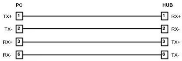
Straight Through
flowchart
graph LR
    PC["PC"] --> HUB["HUB"]
    TX+1["TX+"] --> HUB1["1"]
    TX-2["TX-"] --> HUB2["2"]
    RX+3["RX+"] --> HUB3["3"]
    RX-6["RX-"] --> HUB6["6"]
    HUB1 --> RX+
    HUB2 --> RX-
    HUB3 --> TX+
    HUB6 --> TX-
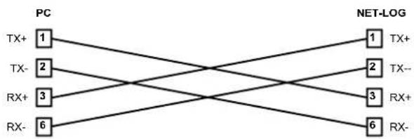
Crossover
flowchart
graph LR
    PC1["PC 1"] -->|TX+| NET-LOG1["NET-LOG 1"]
    PC1 -->|TX-| NET-LOG2["NET-LOG 2"]
    PC1 -->|RX+| NET-LOG3["NET-LOG 3"]
    PC1 -->|RX-| NET-LOG4["NET-LOG 4"]
    PC2["PC 2"] -->|TX+| NET-LOG1
    PC2 -->|TX-| NET-LOG2
    PC2 -->|RX+| NET-LOG3
    PC2 -->|RX-| NET-LOG4
Fig 3-8: Diagram of 'straight through' and 'crossover' CATS cables
3 Set-up & Installation
During all these procedures the messages sent from the Net-Log can be monitored in the Message window. This shows the status of the update with regards to the network settings or firmware updating.
Net-Util also provides various tools for monitoring the status and operation of the connected Net-Log. These functions are available from the menu or by pressing the button showing the right arrow symbol. When this button is pressed, the icon changes to a left facing arrow to indicate that a further press will hide the additional controls. These buttons are shown in Fig 3-9. Whilst running Net-Util, you can place the mouse cursor above the button to show a brief description of the buttons' functionality.

Fig 3-9: Details of Net-Util Tool buttons
The first button on the left in Fig 3-9 simply clears the main messaging window.
The next button allows the serial messages that are sent from Net-Log and displayed on the screen, to also be copied to a text file. This is particularly useful if a problem occurs on the Net-Log as the message window can only display the most recent messages.
The fourth, fifth and sixth buttons select the desired serial message mode. The button marked with a "1" selects minimum mode. In this mode, only details of fatal errors are displayed. The button marked with a "2" selects medium messaging mode. In this mode both fatal and non-fatal error details are displayed.
In maximum mode, selected by pressing the button marked with a "3", system event details are also displayed.
The next button enables network communication monitoring. This feature will display all input and output communications on the connected Net-Log and is intended for debugging purposes only – enabling it will severely affect the network performance of the Net-Log.
The next two buttons are used to display and clear the on-board message log on Net-Log. Each time Net-Log sends a serial message, it adds it to its own internal text log. This log is limited in size and only contains the most recent error/event messages.
The next two buttons are also intended as debug tools although their use will not affect Net-Log's performance. The first is used to display the current status of the network interface on Net-Log. The second is used to display record cut information.
The last button is a "Reset all" button. This will return the connected Net-Log to its factory defaults. (Please note - use of this button will delete all audio on the connected Net-Log.)
Once all the required information has been entered into the Net-Log you are ready to connect the unit to your network.
Ideally, the unit should be connected directly to a switch, but if this is not possible or practical, connecting it to a hub should be sufficient. If you are using the RJ45 connector on the rear of the Net-Log,




you should use twisted pair network cable (i.e. CAT5), wired "straight through" as shown in Fig 3-8.
If you are connecting your Net-Log directly to a network interface card in your PC, then you will require a "crossover" cable, which is also shown in Fig 3-8.
When you have the Net-Log switched on and connected to your PC or network, you can now run the Net-Log-Win software. Read the next section on Start-up and Login, which gives an explanation of the logging procedure and how to enter your Net-Log into the device list.
Note: It is important to fully configure each Net-Log prior to use. Once a successfully connection has been established, refer to section 10 which details all the configuration settings.
4 Startup & Login
4. Startup & Login
Starting Net-Log-Win
To start the Net-Log-Win software, select the icon from your desktop or Start menu depending on how you installed the software. The startup screen will be displayed (Fig 4-1) normally followed by the Login Screen (Fig 4-3). However the first time the Net-Log is used the license manager screen (Fig 4-2) will be displayed.
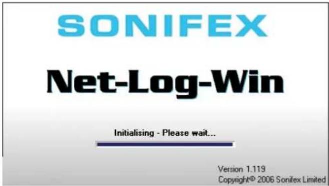
Fig 4-1: The Initialisation Screen
Maximum Concurrent Users
The Net-Log-Win software can be purchased as either a 2-stream license, or as a 5-stream license. This means that you can install the Net-Log-Win software on as many PC's in your network as you like, but that only 2, or 5 simultaneous accesses to the licensed Net-Log can be made respectively. If 2, or 5, users are using a Net-Log and another user tries to access it, a message will be displayed telling them that the allotted number of licenses are already in use.
Remember that if Archiving is enabled, this will use a license.
Multiple Net-Logs On A Network
Only one license is required per network regardless of the number of Net-Logs attached to that network. The first Net-Log connected will need to have a valid license and then all further Net-Logs should be set as slave units and will validate their license from this master. This means that the master will need to be attached at all times. If the master should be removed from the network the slave units will continue to be available for a period of 3 days. After this time they will still continue to record but will be inaccessible from the Net-Log-Win software. Reconnecting the master unit will re-enable all features.
Licensing Your Net-Log
The License Manager Screen (Fig 4-2) is shown when first connecting to a Net-Log or can be accessed from the Administrator menu. This dialogue shows the unique boot code used to validate the master licenses and the 3 licensing options. These allow the user to set the unit as a master by entering the license code; as a slave by entering the TCP/IP address of a connected Net-Log master unit; or define the unit as a demo. Similar to disconnected slave units the demo allows for 3 days of normal operation and the unit can be upgraded at any time to function as a master or as a slave by entering the appropriate data. (Please note - Re-selecting the unit as a demo will delete all audio data and settings from the Net-Log.)
Obtaining License Codes
The license code must be obtained directly from Sonifex. You can do this in several ways, either by phone to Sonifex on +44 (0)1933 650700 during normal UK working hours; or by sending the form from the front of the manual by fax to +44 (0)1933 650726 or directly by post; or by completing the form on the supplied link or through our website www.sonifex.co.uk/netlog; or by supplying the information indicated on the form by email to netlog.support@sonifex.co.uk. Sonifex will endeavour to return the license codes as quickly as possible. In the mean time the machine can be used as a 2-stream license demo machine for 3 days.
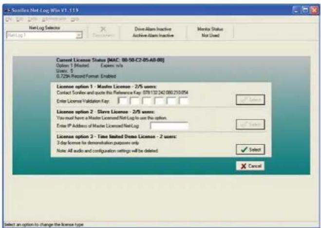
Fig 4-2: The Licensing Screen
The Login Procedure
To enter the system, all users must specify a User Name and a Password.
These will then be compared to details which are stored onboard the Net-Log before the user can access the system. If the user enters the correct information, they will be allowed to use the PC interface to control the designated logger. If the user enters incorrect information, they will be asked to re-enter the User Name and Password.
To configure the system, enter a User Name of "admin" and a Password of "admin". The password should be changed once you are running the program.
There is a Net-Log Device List, which allows you to choose one of any number of Net-Logs connected to the network. When the software is loaded for the first time, no Net-Logs are available in the Device List, and
a message box appears stating this. You will be taken automatically to the Device List editor, where you can add your Net-Log into the list.
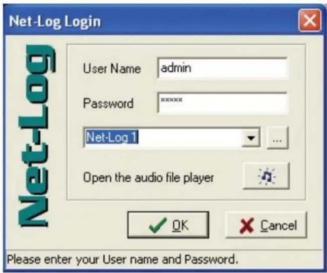
Fig 4-3: The Login Screen
The Device List Editor
To enter a Net-Log into the list you must give it a text name and the IP Address that was downloaded into the Net-Log as described in the "Setup & Installation" chapter. Once you have entered the Name and IP Address into the boxes, press the "Add" button, and it will now appear in the list.
The two up/down arrows on the right hand side are used to select the default Net-Log used when you have multiple units. The default unit is the one that is automatically selected when you login.
4 Startup & Login
Multiple Net-Logs can be Added, Deleted and Replaced. See Fig 4-4.
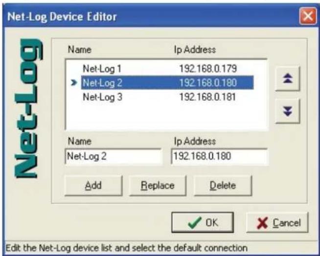
Fig 4-4: The Net-Log Device List Editor
To edit the name or the IP Address of a device, select the unit in the list and edit its details that appear in the Name and IP Address text boxes. When you have finished, click the "Replace" button.
To delete a device contained in the list, select the unit, and then press "Delete". Once you have finished entering the details of your Net-Log(s) into the device list press "OK". This will return you to the Login screen.
Note: Prior to logging on to a new Net-Log for the first time, ensure that the clock on the PC is set correctly as this time will be used to update Net-Log's onboard clock.
The software will attempt to connect to the Net-Log and when a connection has been established you will see the main screen.
If the main screen does not appear then there is a problem connecting to the Net-Log. Check that the IP Address entered in the device editor list is the same as the one downloaded using the Net-Log-Win Serial Utility. Secondly, check that the IP Address and Subnet Mask are valid for your network. If invalid details are entered, the Net-Log will not appear on your network (see your system administrator for more information).
First Time Use of Net-Log
The first time you use the Net-Log you will need to setup the configuration for your particular application. The configuration is accessible from the Options tab. See Chapter 9 for full details. At the very minimum you will need to set up the Record Format, Record Media and Clock Source options.
Changing User Details
Once you have logged in for the first time it is advised that you change your User name and Password from the default settings to stop unauthorised access to your user account. To do this, select the Edit menu, and then User Details (Fig 4-5). Enter your new details and press "OK". If the "Cancel" button is pressed, none of the changes made will take effect.
Note that the password is case sensitive, and you must re-enter the password to confirm it is correct.
There is a special case available to demonstrate just the screen layout and use of the Net-Log-Win software that can be initiated by selecting a user name of demo and leaving the passwords blank.
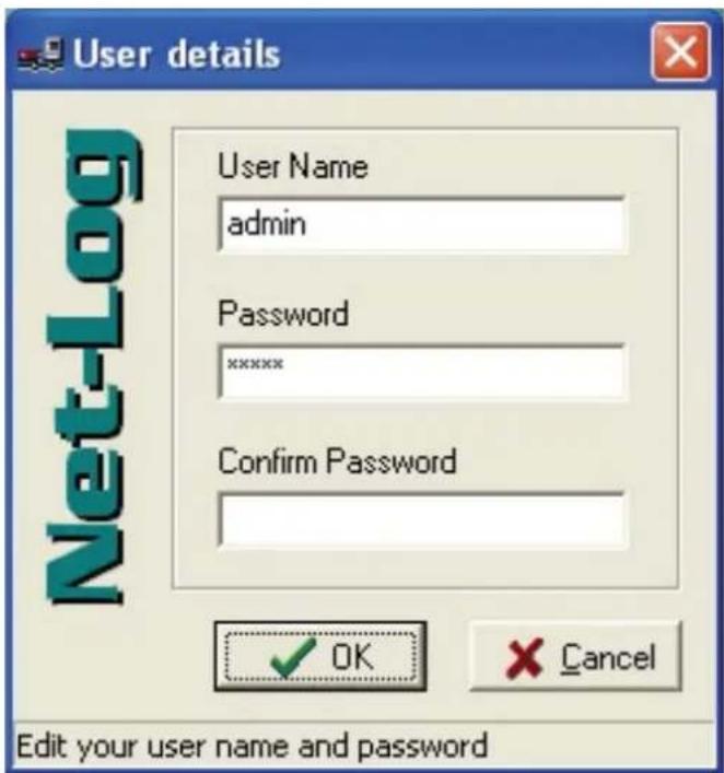
Fig 4-5: User Details
General Screen Layout
After logging in, the main screen appears (Fig 4-6). Whether all of the 4 main selection screens (Record, Archive, Play and Options) are displayed will vary depending on the user account that you have logged in with. However, the screen layout will remain the same throughout.
4 Startup & Login
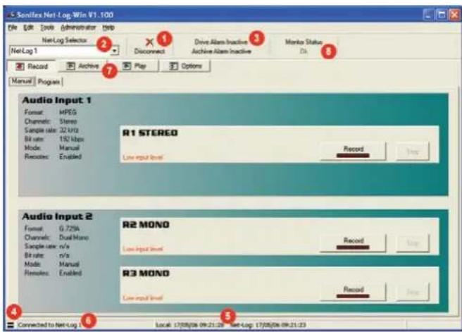
Fig 4-6 General Screen Layout
1 Disconnect/Log-Off Button
If you are currently connected to a Net-Log then this button allows you to disconnect and select a different unit. If you are not currently connected to a Net-Log, this allows you to log off and either log on as another user, or exit the application. Note that logging off, or disconnecting, from the Net-Log will not affect the operation of the Net-Log, i.e. it won't stop it recording, etc.
2 Net-Log Selector
Use this to select other Net-Logs from the drop-down list and connect to them as the user that you are currently logged on as.
3 Alarm Indicators
These replicate the LED alarms situated on the front panel of the Net-Log. The alarm conditions are also available on the remote connector.
4 Network Activity Indicators
These are transmit Tx (left, red) and receive Rx (right, green) indicators showing data transfer between the Net-log and your client PC.
5 Net-Log & PC Time
Date and Time of the Net-Log clock and the local PC clock
6 Status Bar
General information is displayed here.
7 Screen Selection Buttons
These are used to switch between the different screens that are used to control the Net-Log.
8 Mentor Status Indicator
Status of the Mentor Time Server, used for synchronising the PC and Net-Log times on a network.
5. Recording
The Record Screen
This is where all recording actions are controlled. Each input channel (up to a maximum of four mono, or two stereo channels) can be controlled independently and is represented by a separate display panel. Each panel shows the current configuration and state for that channel. For convenience, it also monitors the levels of the audio inputs, and gives an indication of when there is "silence", defined as an input of below -44dB, as shown in Fig 5-1. The record channels are configured using the Options screen.
There are two formats available for recording, MPEG and G.729A. MPEG allows for mono, dual mono and stereo channel selection as well as variable sample and bit rates. G.729A is a high compression, fixed bit rate, mono or
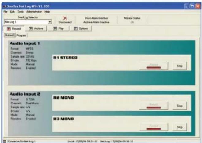
Fig 5-1: Manual Record Screen
dual mono record format. Its low bandwidth makes it ideal for recording speech and gives very high storage capability – approximately 13 minutes per Mbyte. G.729A can be used only after purchasing an additional license. Contact Sonifex Ltd for details.
The Net-Log allows five methods of recording:
Manual Recording
Button presses control recordings on each logger channel.
Program Recording
Record control occurs automatically by defining a "time-sheet" for each channel.
Auto Recording
Record control occurs automatically as the input audio level rises above and below user-defined start and stop threshold levels. Auto record mode is not available when using the G.729A record format.
Remote Recording
Recordings can be started/stopped by connecting certain pins on the rear panel remote connector.
Serial Recording
Record is controlled by commands sent to the Net-Log via the Serial Port. See chapter 8 for protocol information.
Remote or Serial recording will operate regardless of whether Manual, Program or Auto record mode is selected in the Record Options page. Care should be taken to ensure the correct mode of operation is selected as no priority is given to either Remote or Serial recording when co-configured with Manual, Program or Auto record mode.
Note: The Net-Log can record up to a maximum of 250000 tracks on each configured partition on the hard drive. When the end of a partition is reached, recording continues at the start of the partition – over-writing
5 Recording
existing data. Each time the record "loops" back to the beginning of a partition, the track count is reset and a further 250000 tracks are available. Once the 250000-track limit is reached, subsequent recordings will be appended to the 250000th track.
Manual Recording
To start recording manually, select the "Manual" tab, choose the channel you wish to begin recording on and press the relevant "Record Start" button. The Net-Log will start recording and the on-screen LED will illuminate red to indicate this.
Once recording has started, the Record Control button on the front panel of the Net-Log will light up accordingly, and a track list entry will also be created in the play screen. To stop the recording, press the "Stop" button. The Record Control button will change accordingly and the track list entry in the play screen will now contain an end-date and time.
Program Recording
To set-up a program recording you must first make sure that you have a channel enabled to do this. See the Record Format tab of the Options screen – Section 9. Once enabled, you can select the "Program" tab in the Record screen. The Program Record screen will be displayed (Fig 5-2).
This shows a time sheet for a complete week, with the seven days of the week along the left-hand side and the time of day along the top.
Select the record channel that you would like to program by using the left/right arrow buttons.
The time sheet works by defining a Program number and editing the start time and duration. The Program number is then assigned to any of the days by selecting the associated tick-box. Up to 20 Program numbers can be defined.
A graphical representation of the program is displayed.
Note that if you alter a start-time or duration once programmed, the graphic display will alter also to reflect the changes.
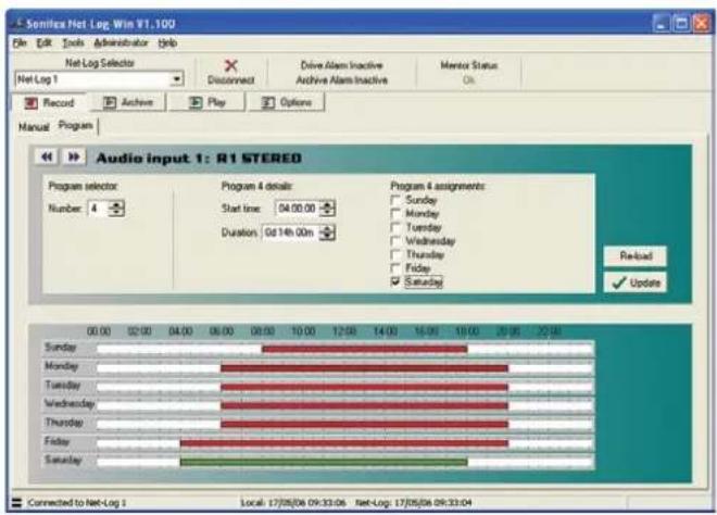
Fig 5-2: Program Record Screen
Additional options are available to assist with setting up the record programs. These options are accessed by pressing the right mouse button whilst the cursor is positioned over the record program screen. A popup menu will be displayed as shown in Fig 5-3. The first two options allows you to quickly assign the currently selected program to either run every day or not run on any day. The next three options can be used to clear programs. Clearing a program resets the start time and duration to defaults and removes all the day assignments. The last two options allow you to make copies of programs.
Run program 4 every day Do not run program 4 on any day
Clear program 4 Clear all programs on this channel Clear all programs on all channels
Copy program 4 to all other programs on this channel Copy all programs on this channel to all other channels
Fig 5-3: Program Record Popup Menu Commands
Click on the "Update" button to send the program to the Net-Log. The record start and stop times are stored on the Net-Log and recording will now start and stop automatically. Storing the information on the Net-Log allows the recording to be made even if there is a network problem at the time the recording state is due to change, and allows everyone to see the record programs being used.
If you need to change the program times for a particular Net-Log, or just want to view them, the display will be refreshed automatically when you select the Net-Log, or you can press the "Re-load" button, which gets the information from the connected Net-Log.
If you make alterations in this screen and wish to cancel them, then simply leave this screen, or press the "Re-load" button to show the existing settings.
Note: If the Net-Log is currently using a program recording, and you update it with a new program, the current state of the recording will reflect the new program state.
E.g. if the Net-Log is recording at 4pm on a Monday and a new program is loaded at that time which has a record stop at 3pm and record start at 5pm on a Monday, the recording will stop. It will then restart recording at 5pm.
Saving and Loading Record Programs
Once you have finished setting up the record programs, you can make a copy of them on a PC. This can be particularly useful if you have more than one Net-Log and you want each machine to follow the same programs.
To save the complete set of record programs for the connected Net-Log, select File, Save As from the main menu. A dialogue will be displayed allowing you to specify the location and name of the file that will be used to store the current program information. Once you have made these selections, press Save.
To load a previously saved file, select File, Open and then select the file that contains the required program information.
Please note, you can only load and save programs whilst in the record program screen.
Auto Recording
To use auto recording, you must first make sure that the auto record mode has been selected, and the auto start and auto stop parameters have been set as required. See the Record Format tab of the Options screen – Section 9.
To start auto recording, press the relevant "Record Start" button. The channel display will show "Waiting for auto start level...", and the Net-Log will start recording automatically when the input audio level rises above the auto start threshold. The on-screen LED will illuminate red to indicate when a channel has started recording.
Recording will continue until the input audio level falls below the auto stop level threshold, at which point the recording is provisionally ended. The input audio level must then remain below the stop level threshold for the period of time set by the stop duration, otherwise recording will continue.
Once a recording has ended, the length of the new cut is compared to the auto start duration. If the new cut length is less than the auto start duration, it will be automatically deleted.
5 Recording
The process is then repeated the next time the input audio level rises above the auto start level threshold.
To stop auto recording at any time, press the "Stop" button.
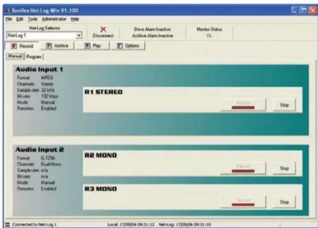
Fig 5-4: Auto Record Mode
Remote Recording
Recording for each channel can also be started remotely using the 15 Pin D-Type socket found on the rear of the unit. There are four record input pins that can be assigned as momentary or latched in the Record Remotes Option screen.
Serial Recording
Serial Recording allows external equipment connected to the Net-Log via a serial communications link, to start/stop recordings. There are currently two interfaces supported. See chapter 8 – Serial Control Interface.
Record Tally Outputs
Each record channel has a 'Record Tally Output' that is active when the associated channel is recording. For example, if channel 1 left is currently recording, then Record Tally Output 1 will be active. Likewise if channel 4 right is also recording, then Record Tally Output 4 will be active. These outputs are independent of the record mode selected.
The Record Tally Outputs are open-collector driven, and are available using the 15 Pin D-Type connector on the rear panel of the unit.
See section 14 Technical Specification for details of all of the remote input and output pin connections.
6. Playing & Downloading
Audio recorded on the Net-Log can be accessed in two ways. Firstly, you can download a selected piece of audio straight to your hard drive, and then play it either using the embedded player (Fig 6-5), or for MPEG, Linear or MP3 recordings, the Windows Media Player. G.729A recordings can only be played using the embedded player. Alternatively, you can stream audio directly from the Net-Log and listen to it whilst it plays.
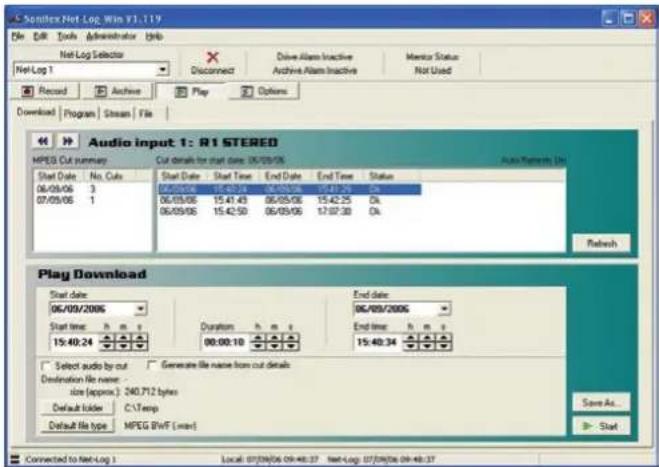
Fig 6-1: Play Download Screen
Track List Display
The track list display is shown in Play Download, Play Stream and Play File. The Net-Log can record up to 250000 tracks per channel. To make it easier and quicker to find the required audio for playback, the recorded track display is split into two parts. The list on the left shows a summary of tracks that exist on the selected channel, indicating the start dates and number of tracks that were started on that date. Click on the required date to load the list on the right with details of each track recorded on that date. The "Refresh" button is used to refresh both lists to include any newly recorded tracks. Select the left/right arrow buttons to change the channel.
The "Cut summary" list is, by default, loaded automatically when entering the play screen, or when selecting a different channel. In addition, both lists will be updated if a new recording is initiated on Net-Log. This auto refresh feature can be disabled by selecting Tools from the main menu, and de-selecting the "Auto Refresh Cut Display" option. It is particularly useful to have this option disabled if you record a large number of tracks on a daily basis, as it prevents the lists being updated every time a new recording is made.
Play Download
Downloading can be used to get a piece of audio from the Net-Log, which can be saved as a file for playback later or for emailing/forwarding to a colleague or customer.
Select the "Download" tab to select the Play Download screen (Fig 6-1). There are two methods of selecting audio for download, by entering the start date and time and the duration of the required piece of audio, or by selecting a track and downloading it in its entirety.
To download a piece of audio by selecting the start date and time, ensure the "Select audio by cut" check box is not ticked. Then click on a track and its time and date details are automatically entered into the Download section. Alternatively, use the right mouse button to load the end time and date of the selected track. This is particularly useful for selecting audio near the end of a track.
The start time, start date and duration can be altered to get the exact piece of audio required. You can also use the end date and time controls to set the effective duration of the required audio. Highlight the hour, minute, second, day, month, or year and by using the up and down spin wheels to alter the value. Alternatively, you can enter the required value directly.
6 Playing & Downloading
The file size is calculated as you change the duration and is displayed below the time and date selection boxes.
To download a complete track, ensure the "Select audio by cut" check box is ticked and select the track to highlight it ready for downloading. Multiple tracks can be selected by holding down the Ctrl key on the keyboard and clicking on additional tracks.
There are several file formats available for tracks recorded using the MPEG format. Press the "Default file type" button to select MPEG BWF, Raw MPEG, Linear BWF or MP3. For MP3 files, the bit rate of the target file can also be selected. Recordings made using the G.729A format cannot be converted to other formats.
Once you have made your selections for play download, press the "Start" button, and if a destination file has been selected the download will start. Otherwise you will be asked to specify a destination file and then the download will start automatically.
The file name for the download can be automatically generated by selecting the "Generate file name from cut details" check box. In this mode, the file name will be based in the start date, start time and duration of the selected piece of audio. When the "Start" button is pressed, the file is created automatically and the download will begin. To use this option, you must have a default directory selected. Press the "Default directory" button to choose the directory where the file will be placed.
For tracks recorded using the MPEG format, the file is created with either a .wav, .mp2 or .mp3 suffix depending on the file type selected. For G.729A tracks, the file extension will be .g7a (see Play File for file type description). MPEG, Linear and MP3 downloads can be played either with the embedded player (Fig 6-5), Windows Media Player or any other capable-software. G.729A recordings however, can only be played on the embedded player, as Windows Media Player does not support this format.
Play Program
The Play Program screen allows audio downloads to be scheduled. Each program contains details of the audio to be downloaded, the format of the downloaded file and an optional date and time when the download is to take place. Each program can specify a single download, or multiple downloads for specific days between selected dates.
Select the "Program" tab to select the Play Program screen (Fig 6-2). The upper part of the screen shows the program summary. This is a list of all pending and active programs for the selected channel. It also shows completed programs that have either not been automatically deleted, or have encountered an error. Select the left/right arrow to change the channel and refresh the program list. The "Delete All" button deletes all programs for all channels.

Fig 6-2: Play Program Screen
The lower part of the Play Program screen shows the details of the selected program. Click on an existing program in the list to load the details. Use the "Delete" button to delete the highlighted program, or the "Replace" button to replace the highlighted program with the program currently shown in Program Details.
To add a new program, press the "New" button. Each program requires a name which uniquely identifies the program in the list. The name can be entered manually, or it can be created automatically by ensuring the "Auto create" check box is ticked.
To configure a program to download a single track, ensure the "Download separate cut for selected days" check box is not ticked. In this mode, the start date and time and the end date and time controls directly select the piece of audio to be downloaded.
To configure a program to download multiple tracks, tick the "Download separate cut for selected days" check box. In this mode, the start and end time controls specify the piece of audio to be downloaded. The start and end date controls specify the range of dates from which the selected piece of audio will be downloaded. The check boxes, marked "Sun" though to "Sat" allow you to select the specific days, between the start and end date, that each track will be downloaded.
For example, you want to download an audio clip that starts at 9:00am and continues to 9:30am on Monday 4th September 2006. You also want to download the same clip from the following Wednesday and Friday mornings. First you would set the start date to 04/09/2006 and the end date to 08/09/2006. Then you would set the start to 09:00:00 and the end time to 09:30:00. With the "Download separate cut for selected days" check box ticked, ensure only the required day check boxes, "Mon", "Wed" and "Fri" are ticked.
The directory where the downloaded audio will be placed is selected by pressing the "Folder" button. When a program download starts, a sub-
directory of the selected folder is created using the program name, and the file is saved to this sub-directory.
For tracks recorded using the MPEG format, the file type of the downloaded audio can be MPEG BWF, Raw MPEG, Linear BWF or MP3. Pressing the "File type" button repeatedly, cycles through the available types. For MP3 files, the bit rate of the created file can also be selected. For tracks recorded using the G.729A format, the file type is fixed.
Once your program selections have been made, you can select whether the program download is to be scheduled for completion at a later time, or started immediately. To schedule the program to run at a later time, select the required date and time using the action date and time controls. You can also select whether the program is automatically deleted once it has completed by ticking the "Auto delete when complete" check box. If you select this option, the program will not be deleted from the list if an error occurs during the download. Press the "Add" button to add the program to the list. To execute the program immediately, press the "Start" button. In this mode, the program will be added to the list temporarily while download is completed. Once complete, the program will be removed from the list provided no errors occurred during download.
A small green tick will appear next to the program name for programs that have successfully completed. A yellow triangle with an exclamation mark indicates programs that have encountered an error. An hour glass next to a program in the list indicates that the program is currently active. By default, the progress of play programs is logged to a file on the PC. See section 11 Tools for details of the play program log.
Play Stream
Select the "Stream" tab to select the Play Stream screen (Fig 6-3). Select the left/right arrow to change the channel. Only one mono or stereo channel can be played at any one time. Select the track that contains the piece of audio that you want to stream.
6 Playing & Downloading
The start time will be entered in the Stream section of the display. Alter the time and date of the track to the time and date of the recording that you wish to hear.
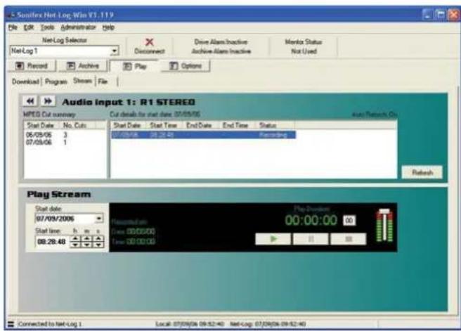
Fig 6-3: Play Stream Screen
Press the "Play" button to hear the audio. It will take a few seconds to access the audio from the Net-Log and to stream it across your network. The Recorded Time and Recorded Date are displayed during playback. You can use the "Pause" and "Stop" buttons to pause and stop the audio respectively. Pressing the "Stop" button will recue the audio back to the "Play from ..." time and date. The slider on the right can be used to alter the volume of playback and the "00" button is used to reset the "Play Duration" counter.
There is a minimum delay for playing audio from a currently recording track. If the selected play time is within this minimum time, a message box will be displayed allowing play to automatically start playing once sufficient audio data exists. See Fig 6-4 for details of the minimum play stream delays.
| Sample Rate Minimum Delay Times for Play Stream on Currently Recording Track |
| 16 kHz 115 seconds |
| 22.05 kHz 85 seconds |
| 24 kHz 79 seconds |
| 32 kHz 60 seconds |
| 44.1 kHz 45 seconds |
| 48 kHz 42 seconds |
Fig 6-4: Minimum Play Stream Delays
Play File
Select the "File" tab. The Play File screen shown in Fig 6-5 is for playing archived or downloaded files. The screen layout is similar to the Play live screen.
The Play File screen is split into two parts; play control and the play list. Audio files are loaded into the play list by pressing the "Open..." button, and selecting the required file(s). Audio files of all supported formats can be loaded into the play list. Single entries in the play list can be deleted by highlighting the entry and pressing the "Delete" button. Alternatively, the whole play list can be cleared by pressing the "Clear" button.
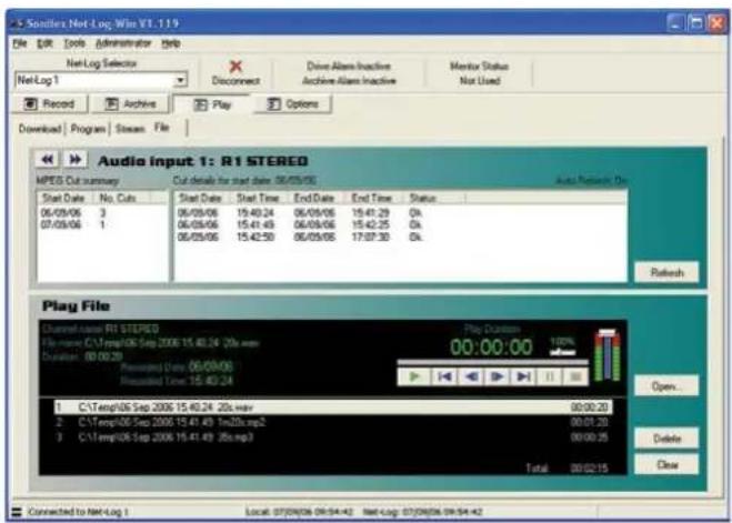
Fig 6-5: Play File Screen
To play the current play list, press the green "Play" button. Play starts at the entry highlighted in the play list and continues to the end of the list. There are other controls including next/previous track select, seek, pause and stop with an extra control for altering the playback speed of the file. This is situated alongside the volume control. The volume control is equivalent to the Wave Output volume control on the Windows Mixer, usually situated in the Windows System Tray.
When an MPEG file is archived or downloaded from the Net-Log, the file can be created as either a raw mpeg data file (.mp2), or as a broadcast wave format file (.wav). Creating a broadcast wave format (bwf) file allows additional information about the recording to be stored and recalled on playback. Creating an mp2 file doesn't allow this information to be recorded. G.729A files are created with this additional information automatically included.
The MPEG bwf and G.729A recordings contain information specific to the file, including the recording format of the file, the origination time of the file, the MAC Address of the Net-Log that it was recorded on and the name of the recording, etc. The origination time and date of the file, together with the file name and file duration, are displayed when the corresponding entry in the play list is selected or played.
7 Archiving
7. Archiving
The Archiving Process
Archiving is the process of getting Net-Log to automatically and continuously create audio files (.wav, .mp2 or .g7a files) on a selected drive or device. Long recordings can be re-formatted into smaller files of a fixed duration for ease of use.
Typically, this is so that a long-term archive of recorded material can be stored on a separate hard-drive, such as on a server, where many people can access historic files without interfering with the operation of the Net-Log. Additionally, the server could then be used to make permanent archives on to CD-R, DAT, or DVD-R, using conventional low-cost IT technology.
Configuring Archival To A Networked PC
Enter the Options screen and select the "Archive" tab (Fig 7-1). To configure the options correctly you need to know the IP Address of the networked PC and the designated share name of the folder to which you want to archive to. You must also have write access to this folder.
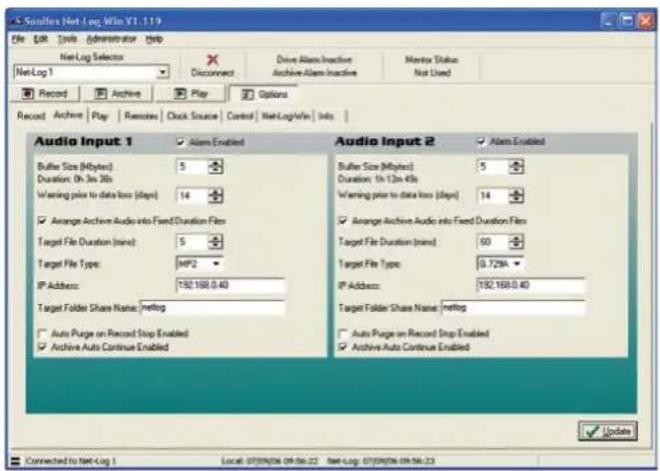
Fig 7-1: Archive Options Screen
Archiving is configured for individual recording channels, or pairs of channels, depending on the recording options settings. For each channel, the following settings should be configured:
Alarm Enabled
This option allows you to disable the archive warnings and alarms. It is primarily for users who don't wish to use Archiving and therefore don't want the distraction of having the archive warnings and alarms activating when data is overwritten.
Buffer Size
The buffer size (5-1000Mbytes for MPEG, 1–200Mbytes for G.729A) is the amount of un-archived data stored on the Net-Log before archiving will start. If you set the buffer to 150MB, the Net-Log waits until it has that much data before it archives to the selected destination. The size of the buffer you select is really dependent on network activity. If your network is quite busy you might want to set the buffer at a relatively low size (5-50MB).
Warn Time
In normal operation, the Net-Log records continually, overwriting information initially recorded on the drive when it reaches the end. The warn time is the amount of time prior to data loss on the Net-Log (5 mins to 14 days) and provides a warning that data will soon be overwritten which has not been archived. Once data is overwritten, the archive alarm will activate. Please note that if you have a busy network you should set this time quite high to give enough time to archive the data. This option has no effect if the Alarm Enabled option is disabled.
Arrange Archive Audio into Fixed Duration Files
When this box is ticked, the audio transferred from the Net-Log to the archive destination drive will be split into fixed length files, determined by the Target File Duration option. Without this option enabled, the audio files will appear on the archive destination drive as they do on the Net-Log.
Target File Duration
This is the duration (5 – 60mins) of the files that will be created on the destination drive. For example, if it is set to 5 minutes then the files on the target drive or device will be of a five-minute duration. This option is only valid when the "Arrange Archive Audio into Fixed Duration Files" box is ticked.
File Type
This determines the type of file that is created (.wav, .mp2 or .g7a).
Destination IP Address
This is the IP Address of the PC on the network that you want to archive to.
Target Folder Share Name
This should be set to the share name of the folder where you want the archives to be stored at the destination IP Address. Only the share name should be entered, not the path of the shared folder. To find the share name, locate the target folder in Windows Explorer, then right click on this folder and select "Properties", then "Sharing" from the popup menu. When the archive begins, sub-folders will be created automatically.
Auto Purge on Record Stop Enabled
When this box is ticked, all available audio is archived each time a recording is ended.
Once you are happy with the settings, press the "Update" button, and they will be written to the Net-Log shown in the Net-Log selector.
Format of Archived Files
The archived files are stored in sub-directories beneath the directory name that you have defined. The format is (depending on the selected file type):
\IP Address\Service Name\dd-mm-yyyy\hh-mm-ss.wav
or
\IP Address\Service Name\dd-mm-yyyy\hh-mm-ss.mp2
or
\IP Address\Service Name\dd-mm-yyyy\hh-mm-ss.g7a
Where IP Address is the Net-Log's IP Address, Service Name is that defined in the Service Name tab of the Options, dd-mm-yyyy represents the date of the recording in day-month-year format and hh-mm-ss is the start time of the recording in hours-minutes-seconds format.
7 Archiving
Beginning to Archive
To start archiving, select the Archive screen and press the "Archive Start" button (Fig 7-2) for the particular channels that you wish to archive.
The LED in the button will illuminate when data is being archived (i.e. transferred from Net-Log to the PC).
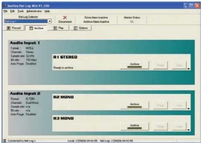
Fig 7-2: Archive Screen.
If you want to stop the archive process, simply select the "Stop" button.
Note: You can only archive audio data from the Net-Log that you are currently logged on to. If you disconnect, all archiving will stop. See section 12 – Auto archive, for details of how to archive data from one or more Net-Logs simultaneously and without having to logon/logoff.
8. Serial Control Interface
The Serial Control Interface allows external equipment to remotely control several functions of the Net-Log. Each of the available interface protocols have been designed according to customers' specific requirements. Additional interface options may be added in the future; please contact Sonifex Ltd for further details.
To enable the Serial Control Interface, enter the Options screen and select the "Control" tab (Fig 8-1). From the drop down list, select the required Control Interface type. If the drop down list is disabled, this means the firmware in the connected Net-Log has not got the Serial Control Interface enabled, or a later version of firmware is required.
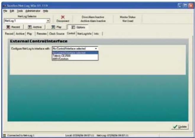
Fig 8-1: Control Options Screen
The Interface types currently available are:
- Televic CE2500
- AMX/Crestron
When a Control Interface type is selected from the list, the available settings for that type will then be displayed.
Televic CE2500 Interface
The Televic CE2500 is the central control unit of Televic's Digital Conference and Interpretation System. This interface provides automatic record start when the Conference Systems' microphones are activated. The recording is then stopped when the microphone is deactivated. The Net-Log also extracts the microphone number and the name of the speaker from the microphone activation command and stores this information on the internal hard disk along with the normal cut information. This additional data is then displayed in the Play screens cut list. The Net-Log can currently support up to 128 microphones.
8 Serial Control Interface
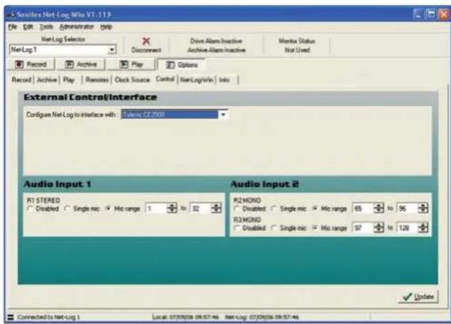
Fig 8-2: Televic CE2500 Interface Options
The settings relating to this interface allow the available record channels to be associated with specific microphone numbers. Each channel is displayed according to the Record option settings. In Fig 8-2, Audio Input 1 is configured as stereo and Audio Input 2 is configured as dual mono. Each available channel is identified by the service name also given in the Record options.
Note: Only one microphone number and name can be stored per recording, so the last one used is stored.
Each channel can be configured in one of three modes:
Disabled
When this option is selected, the channel will not be controlled by any of the microphones on the Conference System.
Single Mic
This selection configures the associated channel to be controlled by a single microphone. The microphone's identification number can be entered in the edit box. Alternatively use the up/down arrows to select the required identification number. The lowest microphone number is 1 and the highest is 128.
Mic Range
This selection configures the associated channel to be controlled by a range of microphones. Activating any one of the microphones in the specified range will start the channel recording. The channel will only then stop recording when all microphones in the range have been deactivated. Again the lowest microphone number is 1 and the highest is 128.
The settings for Single mic and Mic range can overlap such that a microphone can control multiple record channels.
Once the required settings have been entered, press the "Update" button, and they will be written to the Net-Log shown in the Net-Log selector.
The cut list display in the Play screen in Net-Log-Win will now show two additional columns: Mic and Name (see Fig 8-3). These new columns display the Mic number and the Name of the speaker who initiated the recording.
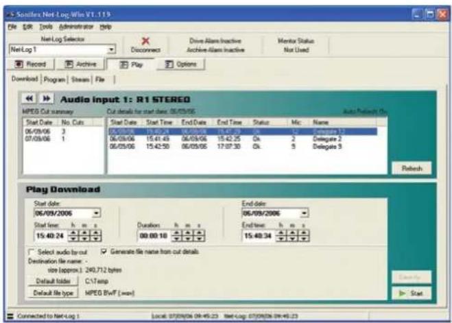
Fig 8-3: Additional Play Cut List Columns
When the Net-Log is powered up with the Televic CE2500 Interface selected, it waits to receive a synchronisation command from the CE2500 before it will execute any further commands. This is to ensure that if any of the microphones are currently activated, and have been previously associated with a record channel, recording is started on the relevant channel. The synchronisation commands are issued by the CE2500 every 5 seconds.
If an attempt is made to stop recording manually in Net-Log-Win on a channel that is associated with an active microphone, a warning message will be displayed in Net-Log-Win.
An alternative method of controlling the recording can be used when using the Televic CE2500 Interface. This is done by utilising the closing contact controlled by the AOP2500 Analogue Output device. This contact is closed when any of the microphones is activated and remains closed until all microphones are deactivated.
By setting all available microphone options to "Disabled" in the Control Options screen, serial control of record start and stop is disabled. Note that the microphone number and name are still recorded in this mode, but because only one closing contact can be used by the AOP2500, only one channel can be recorded, so the microphone number and name are appended to the last recording.
The closing contact on the AOP2500 can then be used to control the remote inputs on Net-Log. See "Record Remotes" in Section 10 for more details on setting up the remote inputs and Section 13 for the pin descriptions of the remote connector.
Televic CE2500 Protocol
The serial settings on Net-Log for the Televic CE2500 interface are as follows:
Serial port: COM2
Baud rate: 19200
Data bits: 8
Stop bits: 1
Parity: none
Flow control: none
The Net-Log responds to 7 of the serial commands issued by the CE2500 unit. These commands share a common structure:
STX ID DATA CRC ETX
where:
STX is the start transmit character ‘%’ (0x25)
ID is a single character which identifies the command
DATA is text associated with the command
8 Serial Control Interface
CRC is the 16 bit sum of the ASCII chars STX, ID & Data
ETX is the end transmit character (0x0D)
Examples of the 7 commands are as follows:
System Synchronisation
"%S0001000201D6\r"
“%” is the start of transmit character (0x25)
"S" indicates command type
"00010002" indicates that mics 1 and 2 are active (0000 for no mics active)
"01D6" is the 16 bit CRC
"\r" is the end of transmit character (0x0D)
President Microphone Activation
"%P0001Mr John Smith05A4\r"
“%” is the start of transmit character (0x25)
"P" indicates command type
"0001" indicates the microphone number
"Mr John Smith" is the speakers name
"05A4" is the 16 bit CRC
"\r" is the end of transmit character (0x0D)
President Microphone Deactivation
"%p00010131\r"
“%” is the start of transmit character (0x25)
“p” indicates command type
"0001" indicates the microphone number
"0131" is the 16 bit CRC
"\r" is the end of transmit character (0x0D)
Delegate Microphone Activation
"%M0002Mr Joe Bloggs058D\r"
“%” is the start of transmit character (0x25)
"M" indicates command type
"0002" indicates the microphone number
"Mr Joe Bloggs" is the speakers name
"058D" is the 16 bit CRC
"\r" is the end of transmit character (0x0D)
Delegate Microphone Deactivation
"%m0002012F\r"
“%” is the start of transmit character (0x25)
“m” indicates command type
"0002" indicates the microphone number
"012F" is the 16 bit CRC
"\r" is the end of transmit character (0x0D)
Deactivate All Microphones
"%V00000116F\r"
“%” is the start of transmit character (0x25)
"V" indicates command type
"0000" indicates no mics active
"0116" is the 16 bit CRC
"\r" is the end of transmit character (0x0D)
System Reset (Deactivate All Microphones)
"%R0052\r"
“%” is the start of transmit character (0x25)
"R" indicates command type
"0052" is the 16 bit CRC
"\r" is the end of transmit character (0x0D)
AMX/Crestron Interface
The AMX/Crestron interface provides simple record control and monitoring for the AMX/Crestron range of Control Panels. These control panels provide a flexible user interface that can be used in addition to the client PCs running Net-Log-Win.
There are no additional configuration options for this interface type. The COM port settings and the protocol commands are fixed.
AMX/Crestron Protocol
The serial settings on Net-Log for the AMX/Crestron interface are as follows:
Serial port: COM2. The serial control interface is implemented on COM2 on Net-Log. Net-Util usually uses COM1 on Net-Log, but when used in Crestron emulation mode, COM2 must be used.
Baud rate: 19200
Data bits: 8
Stop bits: 1
Parity: none
Flow control: none
Operational Note: Flow control is not used. However the Net-Log does assert RTS whenever it has valid characters to transmit. The Net-Util program in Crestron emulation mode asserts RTS all the time. Using Net-Util with the RTS line disabled still works correctly. DCD and DTS are not used. The Net-Log constantly monitors the serial port looking for predefined control characters which signify that a valid command has been received. This control character is set to 0xD (13 decimal) which is the Carriage Return character in ASCII. All data received is buffered internally until this character is received at which point the buffer is closed and validated.
The Net-Log recognises 5 serial commands issued by the AMX/Crestron Control Panel. These commands share a common structure as shown:
CMD DATA NL CR
where:
CMD is the command identifier
DATA is the data associated with the command
NL is the new line character (0x0A)
CR is the carriage return character (0x0D)
The Net-Log issues a reply to all valid commands received. The type of reply depends on the type of command received. For non-data request commands, the reply will either be an acknowledgement or an error code. For data request commands, the reply will consist of the data requested.
Note: The serial commands are case-sensitive.
Speed of Commands & Responses:
The safest and most reliable method of issuing a batch of RS232 commands to the Net-Log, is to send a command and then wait for a response before sending the next command. So for example, if you want to do a status poll of the Net-Log with:
STATUS
TIME:1
TIME:2
TIME:3
TIME:4
you would proceed as follows:
Issue a STATUS command, wait for status info response,
then issue the TIME:1 command, and wait for the time info or error response, then issue the TIME:2 command, and wait for the time info or error response,
8 Serial Control Interface
then issue the TIME:3 command, and wait for the time info or error response,
then issue the TIME:4 command, and wait for the time info or error response
The response time will depend on other factors, such as number of channels recording and archive and play activity. The RS232 port has a relatively low priority to ensure it does not interrupt critical processes.
Record Start Command
Command: "START:ch\n\r"
Reply: "ACK\n\r" or "ERR:ee\n\r"
where: START:= command identifier
ch = channel 1,3 for stereo or 1,2,3,4 for mono
\n\r = new line(0x0A) and carriage return(0x0D)
ACK = command accepted
ERR: = command rejected
ee = error code (see below for error codes)
Record Stop Command
Command: "STOP:ch\n\r"
Reply: "ACK\n\r" or "ERR:ee\n\r"
where: STOP:= command identifier
ch = channel 1,3 for stereo or 1,2,3,4 for mono
\n\r = new line(0x0A) and carriage return(0x0D)
ACK = command accepted
ERR: = command rejected
ee = error code (see below for error codes)
Status Command
Command: "STATUS\n\r"
Reply: "STATE:s1,s2,s3,s4,a1,a2,a3,a4,da\n\r"
where: STATUS = command identifier
\n\r = new line(0x0A) and carriage return(0x0D)
STATE: = reply identifier
s1 - s4 = record channel status 0=not recording,
1=recording,2=unavailable
a1 - a4 = archive channel alarm status 0=no
alarm,1=alarm activated,3=unavailable
Time Command
Command: "TIME:ch\n\r"
Reply: "TIME:ch,t1,t2\n\r"
where: TIME:= command and reply identifier
ch = channel 1,3 for stereo or 1,2,3,4 for mono
\n\r = new line(0x0A) and carriage return(0x0D)
t1 = length of current recording in dd.hh.mm.ss
t2 = time to data overwrite in dd.hh.mm.ss
Date Command
Command: "DATE\n\r"
Reply: "DATE:dd/mm/yyyy hh.mm.ss\n\r"
where: DATE = command identifier
\n\r = new line(0x0A) and carriage return(0x0D)
DATE: = reply identifier
dd/mm/yyyy = current date of Net-Log in GMT
hh.mm.ss = current time of Net-Log in GMT
Reply Error Codes
The following error codes are used for non-data request commands
(START and STOP):
1 = invalid channel
2 = disabled channel
3 = illegal channel
4 = channel already in requested state
9. Options
The Options screens are used for initially configuring the Net-Log before recording. All of the options should be set before Net-Log starts recording, as some of them can not be altered once recording has started.
Saving and Loading Options
Once you have finished setting up the options, you can make a copy of them on a PC. This can be particularly useful if you have more than one Net-Log and you want each machine to share a similar configuration.
To save the options for the connected Net-Log, select File, Save As from the main menu. A dialogue will be displayed allowing you to specify the location and name of the file that will be used to store the current configuration information. Once you have made these selections, press Save.
To load a previously saved file, select File, Open and then select the file that contains the required configuration information.
Please note, you can only load and save options whilst in the options screens.
Record Options
This screen (Fig 9-1) displays the current settings of the two input channels, and also allows them to be changed. Each input is independent of the other, although when they
are set-up for dual mono recording, the two mono channel record settings cannot be configured individually.
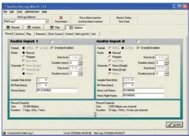
Fig 9-1: Record Options
Disable
Disables the channel.
Override Enabled
Enables this channel to be controlled by the Record Control button on the front of the Net-Log.
Format
Selects the record format, either MPEG or G.729A. Any existing tracks must be deleted from all channels before the record format can be changed. To use the G.729A record format, an additional license must be purchased from Sonifex Ltd.
9 Options
Mode
In Manual mode, recording is started and stopped via the Record Start button in the record screen.
In Program mode recording is automatically started and stopped according to the program for that particular channel. Note: If the mode is set to Manual mode, the Program record screen will not be available.
In Auto Start Mode, recording is started and stopped automatically as the input audio level passes through threshold level settings. Auto Start mode is not available for channels configured to use the G.729A record format.
Channels
Channel format i.e. stereo, mono or dual mono. For G.729A channels, only mono or dual mono configurations are available.
Sample Rate & Bit Rate
Selects the recording parameters for that Input. These settings are only relevant to MPEG configured channels.
When selecting the recording bit-rates for the two pairs of channels, it is important to refer to the maximum number of network connections in Chapter 3.
Start Level
Defines the auto recording start threshold level in dB. When the input audio level rises above this value, recording automatically starts.
Start Duration
Sets the minimum track length in seconds for auto recording. Tracks that are shorter than this value are automatically deleted.
Stop Level
Defines the auto recording stop threshold level in dB. When the input audio level falls below this value, recording provisionally stops.
Stop Duration
Sets the period of time that the input audio level must stay below the stop threshold level to complete the end of an auto recording. This value is in seconds.
Service Names
You can give names to the particular recording channels for easier identification. These names are displayed on the record, archive and play screens and will also be stored in the MPEG BWF or G.729A header of an archive or download file.
Note that once recording has started on a channel, the record format cannot be changed until recording has stopped and all track(s) have been deleted.
Record Capacity
The slide bar at the bottom of the record options screen allows you to select the hard drive partition size for each input. The partition size is the amount of space allocated to each input for storing audio. The bigger the partition the more space is available, allowing for longer recordings. If an Audio Input is set to Mono (Dual), each mono channel will share equally the space allocated for that input.
The duration of the audio recorded to each partition is calculated and displayed. To change the duration for a fixed partition size using MPEG as the record format, the Bit Rate should be set to a new value. A lower Bit Rate means a longer duration and, conversely, a higher Bit Rate means a shorter duration.
Archive Options
This screen (Fig 9-2) displays the current settings for archiving from the Net-Log. See Chapter 7 for more detailed information.
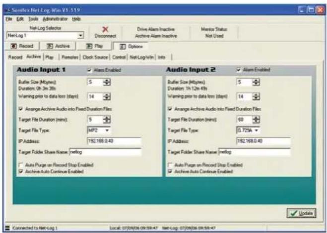
Fig 9-2: Archive Options
Alarm Enabled
Allows data loss warnings and alarms to be disabled.
Buffer Size (Mbytes)
Amount of data that has to be available before archiving can start.
Warn time prior to data loss
Amount of time prior to data loss occurring that a warning is activated.
Arrange Archive Audio into Fixed Duration Files
Formats the archived audio into fixed duration files.
Target File Duration (mins)
The length of the target files. (5 - 60 minutes)
Target File Type
The type of files that are created. The options available for this setting will change depending on the record format selected for this channel.
Destination IP Address
The IP Address of the destination computer.
Target Folder Share Name
The share name of the destination folder on the target computer.
Auto Purge on Record Stop Enabled
Automatically downloads all outstanding audio on a channel when the recording
is stopped.
Archive Auto Continue Enabled
Allows the PC running Net-Log-Win to automatically continue archiving on enabled channels.
Note that some of the settings cannot be changed while archiving is active for a channel.
Play Options
This screen (Fig 9-3) displays the current play default settings. These settings apply to the PC currently running Net-Log-Win and are not saved on the currently connected
Net-Log.
9 Options
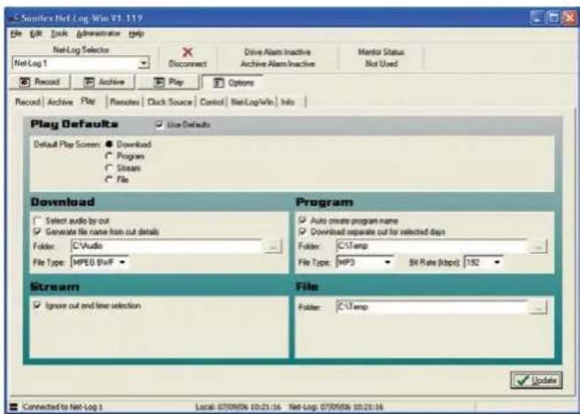
Fig 9-3: Play Options
Use Defaults
Enables all the defaults for play. If this box is not checked, all the defaults are ignored.
Default Play Screen
The selected play screen will be displayed first when entering play.
Play Download Defaults:
Select Audio By Cut and Generate File Name From Cut Details Enables the corresponding options in the play download screen.
Folder
Selects the default folder where downloaded audio files will be written.
File Type and Bit Rate
Selects the default file type to create, and selects the MP3 bit rate when the file type is set to MP3.
Play Program Defaults:
Auto Create Program Name and Download Separate Cut For Selected Days
Enables the corresponding options in the play program screen.
Folder
Selects the default folder where downloaded audio files will be written.
File Type and Bit Rate
Selects the default file type to create, and selects the MP3 bit rate when the file type is set to MP3.
Play Stream Defaults:
Ignore cut end time selection
Disables selection of the cut end time when clicking on the play stream cut list.
Play File Defaults:
Folder
Selects the default folder for opening audio files in the play file screen.
Remotes Options
This screen (Fig 9-4) displays the current settings of the record remote inputs for the Net-Log. The two pairs of audio input channels can be set-up independently. There are three settings for the remotes, and these are:
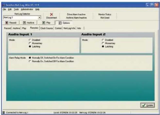
Fig 9-4: Record Remotes Options
Disabled
The remote inputs are disabled for this channel.
Momentary
While the specific pin is connected to ground this channel will be recording.
Latching
Connecting the specific pin to ground for half a second will cause the Net-Log to start recording on that channel. Doing this again will cause it to stop recording.
For information on the remote connector pin connections, please refer to Section 13 - Technical Specifications.
This screen also displays the current settings for the Alarm Relay. The remote connector has a pair of contacts that become connected/disconnected when an alarm condition occurs.
Normally Off, Switched On For Alarm Condition
The contacts on the remote connector are connected when an alarm condition occurs.
Normally On, Switched Off For Alarm Condition
The contacts on the remote connector are disconnected when an alarm condition occurs.
Clock Source Options
When updating the RTC clock, the Net-Log gets it's source from either the clock of the connected PC, or the Sonifex Mentor Server (Fig 9-5). For more information about how
Net-Log uses the time settings see Section 10.
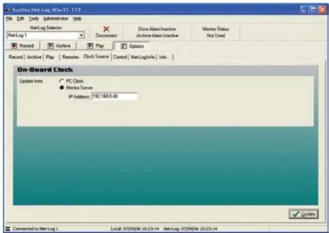
Fig 9-5: Clock Source Options
9 Options
Control Options
This screen (Fig 9-6) displays the currently selected serial Control Interface. If any additional options exist for an interface, these will be displayed when the relevant type is selected. The current options are:
No Control/Interface Selected
The serial Control Interface is disabled.
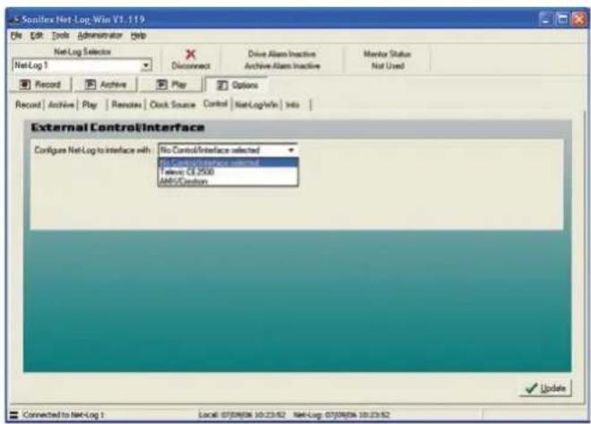
Fig 9-6: Control Interface Options
Televic CE2500
The Serial Control Interface is configured for connection to the Televic CE2500 Digital Conference and Interpretation System. Additional options are displayed for configuring the available record channels to be controlled by specific microphones (see Fig 9-7).
AMX/Crestron
The Serial Control Interface is configured for connection to an AMX/Crestron Control Panel. There are no additional options for this interface type.
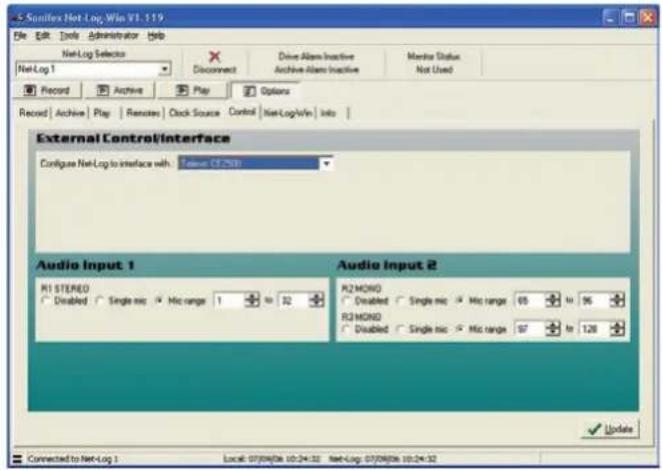
Fig 9-7: Televic CE2500 Control Options
Net-Log-Win Options
This screen (Fig 9-8) displays the options specific to the appearance of Net-Log-Win. Two fonts used in the Net-Log-Win screens can be changed to allow different character sets to be displayed such as Japanese.
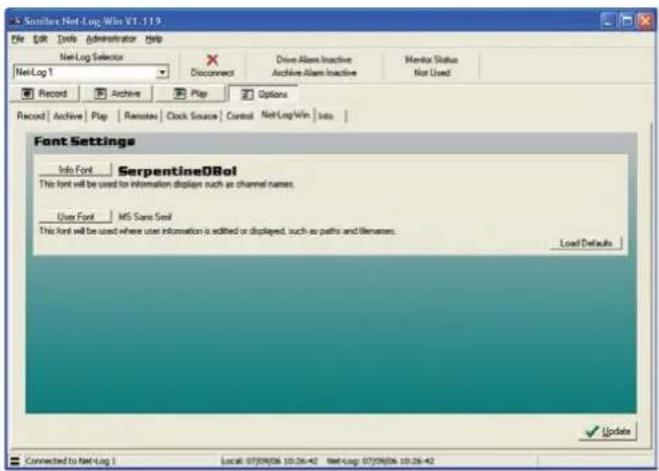
Fig 9-8: Net-Log-Win Options
Info Font
The info font is used to display channel names in the Record, Archive and Play screens.
User Font
The user font is used to display user entered text.
Information
This screen (Fig 9-9) displays general information about the Net-Log. The Network settings are the MAC Address, IP Address, Subnet Mask and Default Gateway for the connected Net-Log. The administrator can change all these settings (except the MAC address) by selecting the Network Settings menu in the administrator menu or by using the Net-Log-Win serial utility, whereby the settings are downloaded to the Net-Log via the serial port. The MAC Address is also stored in the BWF header of an archive or download file.
The Disk Drive Info shows the Model, Serial Number, Firmware Revision and Capacity of the disk drive.
This screen also reports the Remote capability of the Net-Log. Earlier units only had remote input connections on the rear panel mounted the 15-way 'D-Type' connector. These inputs are used to start and stop the recording process remotely. The latest Net-Log hardware has Record Tally Outputs on the 15-way 'D-Type' connector, in addition to the remote inputs, that indicate when the associated channel is recording.
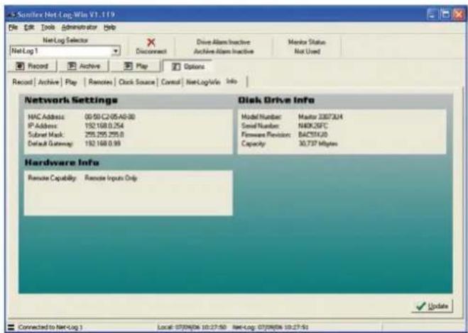
Fig 9-9: Info Options
10 The Administrator
10. TheAdministrator
There are several operations that can only be accessed by the administrator. These include the License entry and Accounts editor screens and they are all accessed through the Administrator menu. (Fig 10-1).
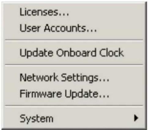
Fig 10-1: Net-Log Administrator Menu
Licenses
This screen displays how many users the Net-Log is licensed for and also allows the administrator to enter more licenses. (See Fig 4-2)
Accounts Editor
The Accounts Editor (Fig 10-2) can be accessed via the Administrator menu option and is used to set-up or change accounts for users who connect to the Net-Log. Below are all the default User Names. Initially the user name and passwords are the same – these can (and should) be altered once the software is running.
"admin"
This is the Administrator's login. The administrator is in charge of defining user profiles and configuring the settings of the Net-Log.
"user1" to "user25"
Up to 25 users can be defined in the software. Each user can be given different access rights for each function – these are described in more detail below.
"guest"
Guest entry allows playback only.
These password settings are stored on the Net-Log machine currently being connected to, so if you have a number of machines, you can change user access to each machine individually.
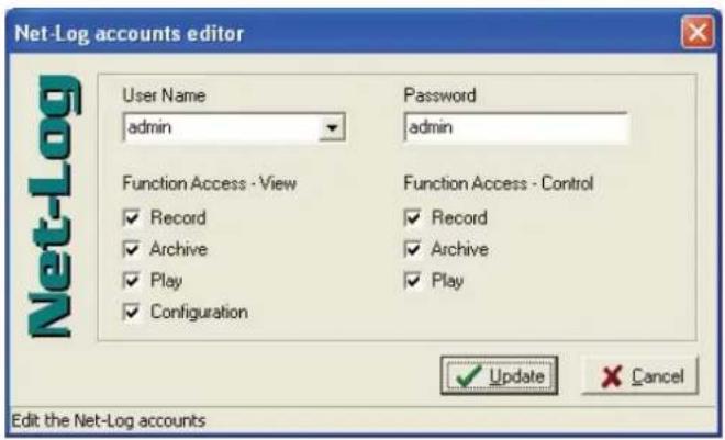
Fig 10-2: Accounts Editor
Function Access - View
There are four check boxes associated with this restriction control (Fig 10-3). If checked, the currently selected user will be able to view that specific function but will not be able to change the operation of that specific function in any way.
Note that the administrator will always have view access to configuration and that this cannot be changed.
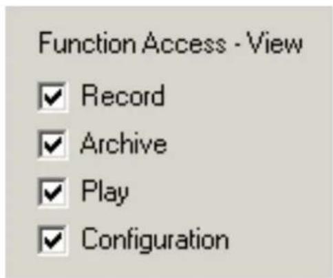
Fig 10-3: Function View
Function Access - Control
There are three check boxes associated with this restriction control (Fig 10-4). If checked, the currently selected user will be able to view and control that specific function.
Note that only one person can have access to archive control and by default this is the administrator.
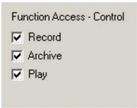
Fig 10-4: Function Control
User Name & Password
To change a user name or password, select the user whose details you wish to change and type in a new name or password (Fig 10-5).
Note that all the changes made will only take effect when the "Update" button is pressed. If "Abort" is pressed then the changes are lost.

Fig 10-5: Select or Edit User Name & Password
10 The Administrator
The Onboard Clock
The Net-Log uses an accurate onboard real time clock (RTC) to record the start & stop times of cuts and to start & stop record programs. This time is stored on the Net-Log in UTC format which is identical to Greenwich Mean Time and is unaffected by any summer or daylight saving time schemes.
The accuracy of the RTC is ± 1.53 minutes per month. This equates to about 3 seconds per day. During long or continuous recordings, an error can develop between the actual time a piece of audio is recorded, and the time used from the RTC to reference the cut. In a worst case scenario, when the RTC is running slightly slow with respect to real time, the audio at the end of a long recording could be unavailable. This is because the time stamp taken from the RTC for the end of the cut would be earlier than the actual time the cut ended. To overcome this, the Net-Log firmware determines whether the RTC derived time for the end of a recording differs from the time the Net-Log calculates the cut should end at. This calculation is made using the start time and length of the recording. Future play or archive accesses to this cut will then use this error figure to bias the search calculation so that the whole cut is accessible.
If the RTC has drifted, then the start time of any new cuts will not be a true reflection of the actual time the recording was started. If the start time for a recording is inaccurate, the time displayed when playing the recording and when searching within it will also be inaccurate. Also, if program record mode is used, the automated record starts/stops will not happen at exactly the right time. It is important therefore, to regularly update the RTC if accurate audio to time synchronisation is required.
Updating The Onboard Clock
The onboard clock can be updated at any time. If an update occurs whilst a channel is recording, and the difference between the current RTC and the time update is greater than two seconds, the recording will stop prior to the clock update. Once the clock has been updated, a new recording will automatically begin. This is done to reduce the error correction required when searching for audio. It also happens so quickly that you will not lose any audio. However there will be a time difference between the two recordings.
There are two options for RTC clock updates. The first is to update Net-Log with the time currently set on the connected PC. This is an administrator only function and it is not automatic. The second option is to automatically synchronise the onboard clock to a specific PC using the Mentor software. It is advisable to have the clock on the PC running the Mentor server accurately maintained from an external source. The Mentor software will then distribute the time information to multiple Net-Logs every 30 minutes.
Whichever update method is used it is very important that any PC used to connect to Net-Log is set for the right Time Zone. Otherwise, the conversion between UTC and local time that Net-Log-Win performs for all time related data, will be incorrect. This is set in the PC Control Panel setting for Date/Time.
It is possible to force a clock update for either of the two clock options by selecting the Administrator menu (Fig 10-1), and then Update Onboard Clock. If you are using the PC clock option and you want to keep the Net-Log clock accurate to within 10 seconds, you will need to do this every 2-3 days.
Network Settings
To change the Network Settings of the Net-Log simply enter the administrator menu and select the Network Settings menu. The screen (Fig 10-6) shows the current settings and next to these are a series of edit boxes where the new settings should be typed. When they have been entered simply press the "Update" button, the settings will then be downloaded to the Net-Log and the application will shut down. Once the Net-Log has re-initialized with new settings you can restart Net-Log-Win. You may need to change the IP Address of the unit in the device editor before you can attempt to log onto the Net-Log.
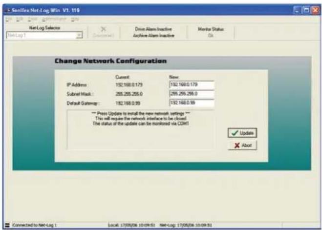
Fig 10-6: Network Settings
Updating Firmware
From time to time updates will be made available to keep the Net-Log running smoothly and reliably. To update the firmware contained in the Net-Log simply select the "Firmware Update" option in the Administrator menu, you will then be given a warning and asked to confirm your action. If "Ok" is pressed, you will then have to select the update file (.dwn suffix). Once this has been done you will be taken to the Net-Log Update Firmware screen. Press the "Transfer" button and the file will then be transferred onto the hard drive contained on the Net-Log (Fig 10-7).
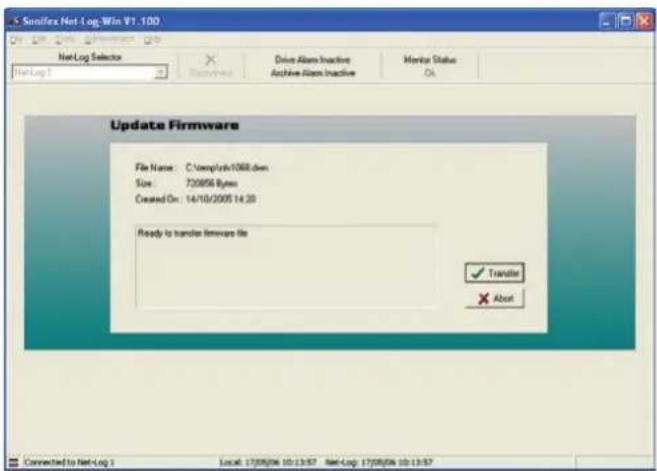
Fig 10-7: Upgrading Firmware
Please note that you can still abort the update even after the transfer has been completed. To commence the actual update, press the "Transfer" button again. The System ROM is then erased and programmed with the updated software (shown by the Record Control button on the front of the Net-Log being lit), after which the Net-Log will restart and is ready for use again. Note that updating the firmware can also be done using the Net-Log serial utility.
For the latest firmware updates check the Sonifex website at www.sonifex.co.uk.
Sometimes, updating the firmware can result in the loss of audio data depending on which firmware version you are upgrading from/to. Information on this is also on the website.
10 The Administrator
Resetting The Net-Log
This option is a sub menu of system in the administrator menu. This is used to restore all the configuration settings to factory defaults. It also deletes all the tracks contained on the Net-Log.
11. Tools
The Tools menu (Fig 11-1) contains a number of useful tools to check on the performance and status of the Net-Log unit. There is also a Delete Cuts submenu, although this is only available to users who have record access.
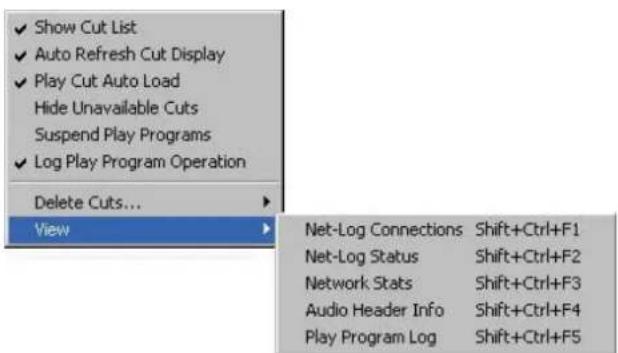
Fig 11-1: Net-Log Tools Menu.
Show Cut List
When this option is not ticked, the cut list display in the play screens is hidden. This option is ticked by default.
Auto Refresh Cut Display
With this option ticked, the cut displays in the Play screen will automatically refresh when a recording is started or stopped, or when you change to a different channel.
Play Cut Auto Load
When this option is ticked, the details of the first recording for the selected Start Date will automatically be loaded into the current Play screen (Play Download or Play Stream).
Hide Unavailable Cuts
When this option is ticked, all recordings that are no longer available due to being over-recorded are hidden from the Play screen cut list.
Suspend Play Programs
When this option is ticked, the execution of Play Programs is halted. Any program download that is currently active will be completed but no further downloads will start.
Log Play Program Operation
When this option is ticked, information about the progress of Play Program downloads is written to a log file. Information includes details about when a download is completed, as well as information on any errors that were encountered during the program, such as failure to locate the selected audio.
Deleting Cuts
This menu option does exactly what it says. When you select this option a sub-menu appears showing all the channels that you are able to delete cuts from. Note that you can only delete cuts from a channel if this channel is not currently recording. The Delete All option automatically deletes all cuts from all non-recording channels.
View
Contained in this menu are five sub-menus. Net-Log Connections, Net-Log Status, Network Stats, Audio Header Info and Play Program Log. Each of these display information about Net-Log's performance and status, and are described in more detail below.
Net-Log Connections
This useful screen (Fig 11-2) displays all users currently connected to Net-Log, and displays their IP Address and connection duration.
11 Tools
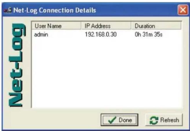
Fig 11-2: Net-Log Connections Screen
Net-Log Status
This screen (Fig 11-3) displays the status of the Net-Log and All the Input Channels. Described over leaf are all the status indicators.
Drive Alarm
Problem writing to the Disk. (Equivalent to the LED on the front panel). This Alarm is cleared only once the fault has been rectified.
The next 3 indicators give momentary indication of a change in state of the appropriate feature
Cut Change
Indicates a recording start/stop or cuts being deleted.
Program Change
Programs have been changed.
Config Change
Configuration settings have been changed.
Record Auto Enabled
Auto record mode is enabled on the specified channel.
Record Active
Net-Log is currently recording on the specified channel.
Archive Enabled
Archive is enabled on the specified channel.
Archive Pending
Net-Log has data ready to archive for the specified channel but Archiving is not enabled.
Archive Auto Purge
Archive will transfer all available audio data for the specified channel.
Archive Active
Data is currently being archived from the specified channel.
Archive Warn
Loss of data is about to occur on the specified channel.
Archive Alarm
Loss of data is has occurred on the specified channel.
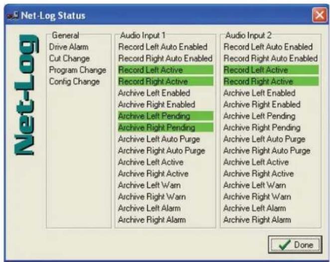
Fig 11-3: Net-Log Status Screen
Network Stats
This screen (Fig 11-4) displays the rate of transmission between the Net-Log and connected Client, and also displays the status messages transmitted to and from the Net-Log. This is useful for network traffic monitoring.
Tools 11
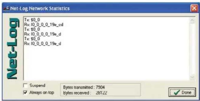
Fig 11-4: Net-Log Stats Screen
Audio Header Info
This screen (Fig 11-5) shows detailed information about the audio cuts on the selected Net-Log. It is mainly for debugging purposes.
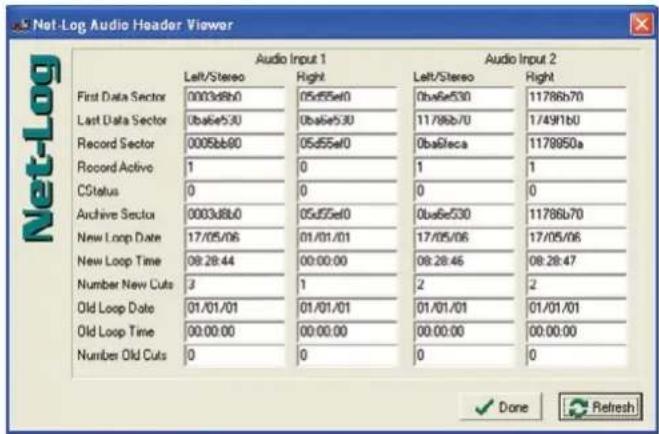
Fig 11-5: Net-Log Audio Header Info Screen
11 Tools
Play Program Log
This screen (Fig 11-6) shows information on the progress of any Play Programs that have been executed. Its main use is to determine the cause of any errors that were encountered.
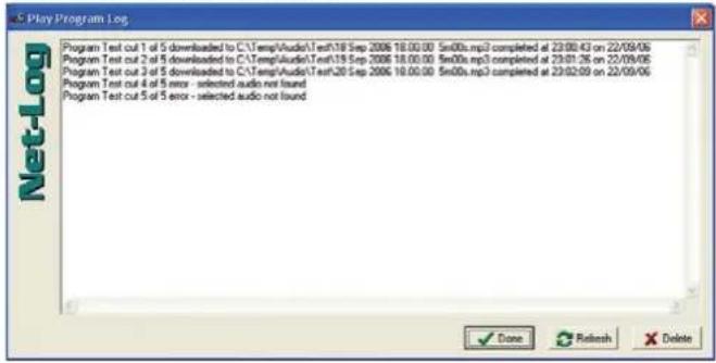
Fig 11-6: Play Program Log Screen
About Sonifex Net-Log
This screen (Fig 11-7) accessible from the help menu shows the software versions of the Net-Log-Win and the currently connected Net-Log. The current status of the License on the currently connected Net-Log is also shown here. The information on this screen is mainly used for debugging and version checking.
![About Sonifex Net-Log-Win Net-Log-Win Copyright © 2006 Sonifex Limited - All rights reserved. Version Information: Net-Log-Win: 1.119 Net-Log-Win stream filter: 1.001 Net-Log base: e Net-Log: 1.108 [011] License Information: Option: 1 (Master) Expires: n/a Users: 5 G.729A Record Format: Enabled Hard Drive Information: Model Number: Maxtor 33073U4 Capacity: 30,737 Mbytes MAD MPEG Audio Decoder Information: Version: 0.15.1 (beta) LAME MP3 Encoder Information: lame_enc.dll version: 1.32 (29/07/2004) lame_eric_Engine: 3.96 lame_eric_homepage: http://www.mp3dev.org/ Sonifex home page ✓ OK](/content/2026/05/835038/images/7bc813bc1b12529307e97f292f0dd55c16e697144b2e0e64423926919ede7e1e.jpg)
Fig 11-7: Net-Log About Screen
12. Auto-Archive
Introduction
Auto-Archive can be used to archive audio, control the recording process and schedule recording of up to twenty Net-Log units simultaneously. Using Net-Log-Win to archive material from a Net-Log unit to a PC/Server requires a user to manually log-on to the Net-Log, initiate archiving and remain logged-on for the duration of the archive process. Whilst this is satisfactory for most set-ups with one Net-Log unit, a more automated solution is required for installations of two or more Net-Log units. Net-Log Auto-Archive can be used with up to twenty Net-Logs simultaneously, automatically logging-in, archiving the available material and logging-out.
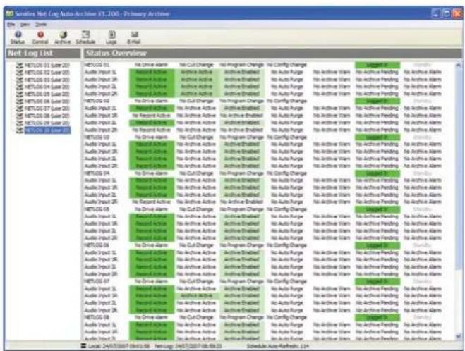
Fig 12-1: The Status Screen
Licensing
When connecting to a Net-Log unit, an available stream license is required to perform the archiving process.
Using Net-Log-Win, it is suggested that a user (such as User20) is defined as having 'Archive Control' and 'Record Control', but no 'Play Control'. Auto-Archive will then only use one stream license when connected to a Net-Log unit.
When Auto-Archive logs on to the Net-Log, it uses one of the user accounts to do this. See "The Settings Screen" later in this chapter for information on defining the User Name used for auto archiving.
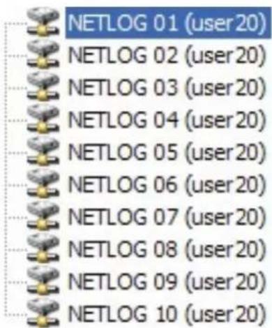
Fig 12-2: The Net-Log List
The Net-Log List
The Net-Log Auto-Archive screen displays the defined list of Net-Log units down the left side. When a particular unit has been logged-on, the User Name is displayed in brackets. See Fig 12-2. This list can be edited by selecting Tools from the main menu, and then selecting Settings.
The Status Bar
The status bar has transmit (Tx) and receive (Rx) indicators, which can be viewed to confirm the connection to the selected Net-Log.
12 Auto-Archive
Performance
Please note that the performance of Auto-Archive depends upon the network and PC architecture, number of Net-Log units and the bit rate of the archives being created.
System Set-up
Net-Log units are equipped with 10mb/s network interfaces that should be connected directly to a 10/100 or 10/100/1000 capable Ethernet switch. The archiving PC/server should be fitted with at least a 100mb/s network interface. If possible use a 1000mb/s network interface, especially if multiple Net-Logs are being archived with high bit rates (e.g. 384kb/s stereo, or 192kb/s mono).
Starting The Archive
Before the archive process can begin, the Auto-Archive utility has to Login to the Net-Log(s). This is achieved in one of two ways. To manually connect to a Net-Log, right click on the Net-Log name on the left side on the screen and then select Connect. Once a connection has been established, and the archive rights of the account used to logon to the Net-Log has been confirmed, archiving can begin. Auto-Archive will then stay connected to the Net-Log until it is manually disconnected. To do this, right click on the Net-Log name and select Disconnect. For a more automated setup, Auto-Archive can be set to automatically Login to the configured Net-Logs, check for and archive outstanding audio, and then Logout. See the Auto Login/Logout option in the Device List later in this chapter for details.
The Settings Screen
To access the Settings screen, select Tools from the main menu, and then select Settings. The screen shown in Fig 12-3 will be displayed.
Device List
Define your list of Net-Log units using the 'Add', 'Replace', and 'Delete' buttons. To fully automate the archive process, select the Auto Login/Logout checkbox to allow Auto-Archive to automatically login to each configured Net-Log at regular intervals and archive outstanding audio. This option must be set individually for all required Net-Logs.
To enable successful archiving on each Net-Log, be sure to use the User Name and password that has 'Archive Control' rights.
When connecting to a Net-Log unit, an available stream license is required to perform the archiving process.
Using Net-Log-Win, it is suggested that a user (such as User20) is defined as just having 'Archive Control' and no 'Play Control', and this user used by Net-Log Auto-Archive.
See chapter 10 for more information on licensing and users and rights.
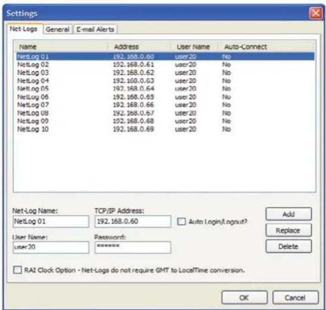
Fig 12-3: Net-Log Device List
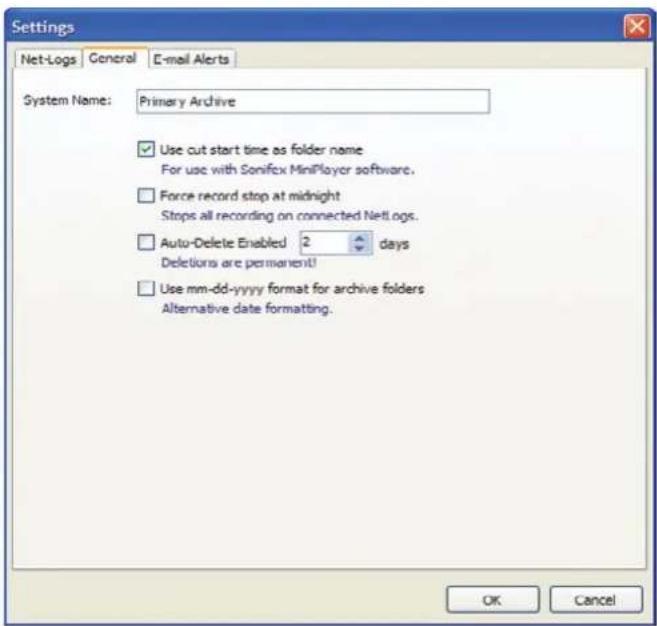
Fig 12-4: The Settings Screen
System Name
Enter a meaningful name to describe this particular system. This name will appear in the applications caption bar and any emails sent from this system. This can be especially useful if two or more Auto-Archive systems are in use.
12 Auto-Archive
Force Record Stop at Midnight
With the force stop option checked all recording channels will be forcefully stopped at midnight. This feature requires Auto-Archive to be logged-in to the Net-Log units over the turn of midnight.
Auto-Delete Archives
If Auto-Delete is enabled, previously archived material will be deleted after the specified number of days.
Use mm-dd-yyyy Format for Archive Folders
Check this option if you require the archive folder names to use the mm-dd-yyyy format and not the default dd-mm-yyyy format.
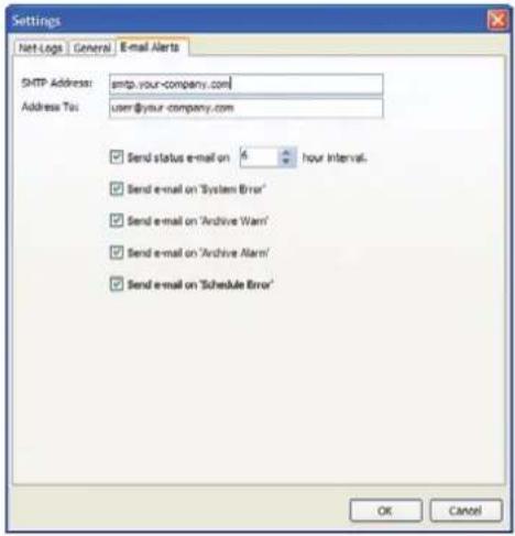
Fig 12-5: The Settings Screen
These options are used to configure the sending of the e-mailed status reports.
- SMTP Address – TCP/IP address of your e-mail server.
- Address To – E-mail address of recipient. Must contain only one address and in the format: user@your-company.com
- Interval – Interval (in hours) between sending of Status Reports. Suggest setting this between '6' and '24' hours.
- E-mail Status Report – option to send/not send Status Reports.
- E-mail Error Report – option to send/not send Error Reports.
- E-mail 'Archive Warn' – option to send/not send 'Archive Warn' reports.
- E-mail 'Archive Alarm' – option to send/not send 'Archive Alarm' reports.
- E-mail 'Schedule Error' – option to send/not send 'Schedule Error' reports.
See later in this chapter for a description of these reports.
The Status Screen
The Status screen displays the current known status of each defined Net-Log unit.
See Fig 12-6.
To view the Status Screen, press the 'Status' button on the toolbar.
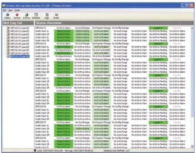
Fig 12-6: The Status Screen
If auto-login and/or auto-logout are enabled, this screen also shows the login and log-out countdown timers for each Net-Log unit.
The Control Screen
The Control Screen can be used to start and stop recordings, and also start and stop the archive process on each of the designated Net-Log units. See Fig 12-7.
Archive LED states:
- Flashing Yellow : Archive Pending
• Steady Yellow : Archive Active - Flashing Red : Archive Warn
• Steady Red : Archive Alarm
- Off : No Archive Pending
To view the Control Screen, press the 'Control' button on the toolbar.
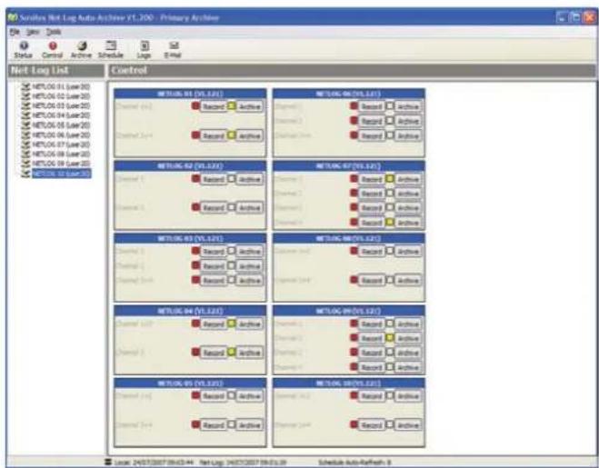
Fig 12-7: The Control Screen
The Archive Screen
The Archive Screen can also be used to control the archive process of the currently selected Net-Log. See Fig 12-8.
This screen also shows record parameters, archive settings and displays the filenames of archives currently being written to disk. See Chapter 9 on the use of the Archiving settings.
12 Auto-Archive

To view the Archive Screen, press the 'Archive' button on the toolbar.
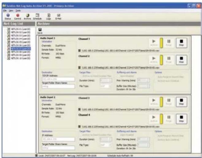
Fig 12-8: The Archive Screen
The Event Log Screen
The Event Log Screen lists noteworthy events in chronological order. See Fig 12-9.
Such events include:
- connections/disconnections with Net-Log units
- important information regarding failure to properly archive material
• confirmation of sent email reports
To view the Event Log Screen, press the 'Log' button on the toolbar.
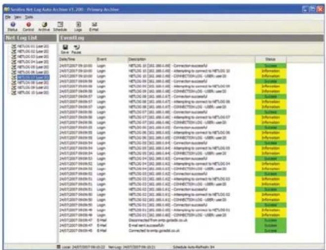
Fig 12-9: The Event Log Screen
Reports
There are a number of e-mailed reports available from Net-Log Auto-Archive.
Status Report
The general Status Report includes information regarding the known current state of all defined Net-Log units, including Login/logout timings and audio input status.
This report can be generated manually by pressing the 'E-Mail' report button on the toolbar.
Error Report
Error reports are generated when a communication error has occurred with a single Net-Log unit. The error type will be included within the report. Whilst some of these errors will be critical (such as 'Connection Error'), some are not (such as 'User Unavailable')
Possible Errors
- 'Invalid User Name' – User Name is not recognised by Net-Log unit. Check Options.
- 'Invalid Password' – password is not recognised by Net-Log unit. Check Options.
- 'User Unavailable' – user is already logged-in. Check connected users with Net-Log-Win.
- 'No/Bad Response' – connection broken. Check network cabling.
- 'No Valid Licenses' – Net-Log has not been licensed. Use Net-Log-Win to issue a license.
- 'Valid licenses in use' – all licenses are in use.
- 'Connection Error' – unable to connect to Net-Log. Check network cabling.
- 'No Disk Space!' – archive target has no useable space remaining. Change archive destination or make some space available.
Archive Warn Report
'Archive Warn' reports are generated when a Net-Log input channel is about to overwrite material that has not yet been archived. This usually happens when the input channel has not been 'Archive Enabled'.
Archive Alarm Report
'Archive Alarm' reports are generated when a Net-Log input channel is overwriting material that has not been archived. This usually happens when the input channel has not been 'Archive Enabled'.
Startup/ Shutdown
Auto-Archive automatically sends a confirmation email whenever the application is started or closed.
The Schedule
From version 1.200, Net-Log Auto-Archive can be used in conjunction with the Sonifex Net-Log Scheduler application (see Chapter 13) to start and stop scheduled recordings on up to twenty Net-Log units.
The Schedule Database
The schedule is stored within a local Microsoft Access database file called 'schedule.mdb' and can be found in the 'c:\program files\sonifex\net-log auto-archive\schedule' folder.
Network Scheduling
If you plan to use the Net-Log Scheduler application on a different computer to that of Net-Log Auto-Archive, then the folder where the schedule database is stored needs to be shared.
12 Auto-Archive
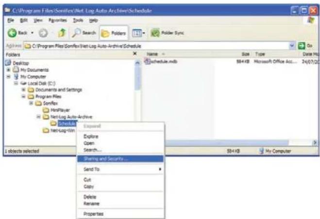
Fig 12-10: Sharing and Security Selection
Locate the 'c:\program files\sonifex\net-log auto-archive\schedule' folder using Windows Explorer, right-click and select 'Sharing and Security' from the menu.
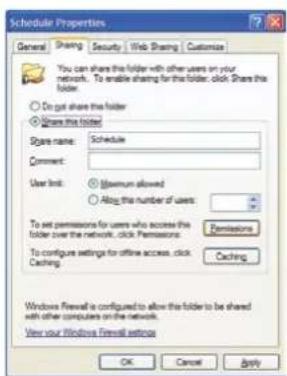
In the 'Schedule Properties' tab, select 'Share this folder' as 'Schedule'. Then press the 'Permissions' button.
Fig 12-11: Schedule Properties Screen
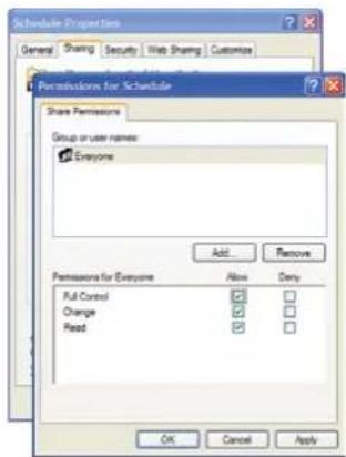
In the 'Permissions for Schedule' tab check 'Full Control' to 'Everyone'.
The press the 'OK' button.
Fig 12-12: Permissions Screen
The Schedule Screen
The scheduling feature of Net-Log Auto-Archive can only be accessed if the computer has a Sonifex D:Scribe Server dongle fitted.
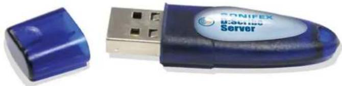
natural_image
Blue USB device labeled 'SONIFEX HABIBUS Server' next to a blue plastic case (no additional text or symbols visible)Fig 12-13: D:Scribe Dongle
To open the Schedule Screen, press the 'Schedule' button on the toolbar, or select 'View->Schedule Screen' from the menu.
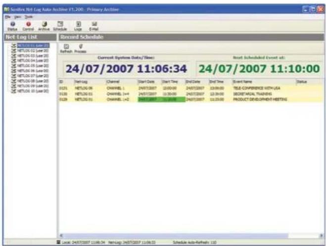
Fig 12-14: Primary Archive Screen
The Schedule Screen shows a list of current and passed scheduled recording events. Auto-Archive cannot be used to add to, edit or remove events from the schedule, this can only be accomplished through the Net-Log Scheduler software.
Auto-Archive can only successfully start and stop recordings from the schedule when the required Net-Log is online and logged-in with a user of sufficient rights to the record process.
13 Net-Log Scheduler
13.Net-Log Scheduler
Introduction
The Net-Log Scheduler application is used in conjunction with Net-Log Auto-Archive to schedule recordings on upto twenty Net-Log units.
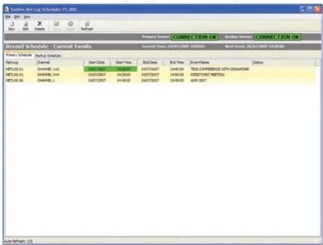
Fig 13-1: Net-Log Scheduler's Listing
The user can add new events, edit existing events, and delete events from the schedule. The schedule listing is automatically refreshed every two minutes to show additions and changes that may have been made from another computer. Alternatively, the listing can be refreshed manually by pressing the 'Refresh' button on the toolbar.
Database Connection Status
The status of the connections to the two databases is displayed at the top of the window. Each status indicator should read "CONNECTION OK", but could read "FAILURE" in the event of server or network failure / maintenance.
Primary and Backup Schedules
The Net-Log Schedule application can be configured to use up to two databases on separate Auto-Archive computers. This arrangement can be used as a primary and a backup system.
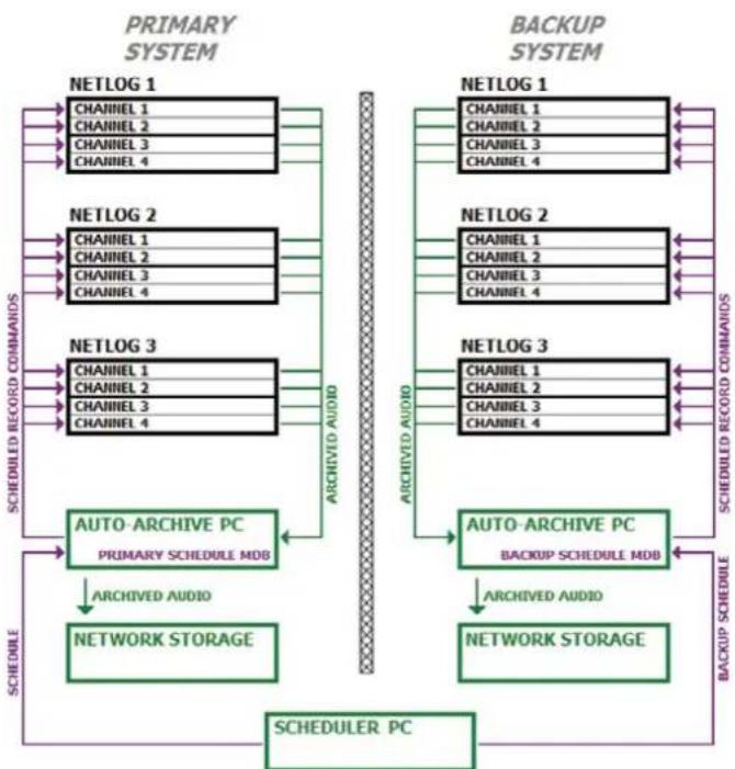
flowchart
graph TD
    subgraph_PRIMARY_SYSTEM["PRIMARY SYSTEM"]
        A1["NETLOG 1"] --> B1["CHANNEL 1"] --> C1["CHANNEL 2"] --> D1["CHANNEL 3"] --> E1["CHANNEL 4"]
        A2["NETLOG 2"] --> B2["CHANNEL 1"] --> C2["CHANNEL 2"] --> D2["CHANNEL 3"] --> E2["CHANNEL 4"]
        A3["NETLOG 3"] --> B3["CHANNEL 1"] --> C3["CHANNEL 2"] --> D3["CHANNEL 3"] --> E3["CHANNEL 4"]
        A4["SCHEDULED RECORD COMMANDS"] --> B4["ARCHIVED AUDIO"]
        B4 --> C4["AUTO-ARCHIVE PC PRIMARY SCHEDULE MDB"]
        C4 --> D4["ARCHIVED AUDIO"]
        D4 --> E4["NETWORK STORAGE"]
        E4 --> F["SCHEDULER PC"]
    end

    subgraph_BACKUP_SYSTEM["BACKUP SYSTEM"]
        G1["NETLOG 1"] --> H1["CHANNEL 1"] --> I1["CHANNEL 2"] --> J1["CHANNEL 3"] --> K1["CHANNEL 4"]
        G2["NETLOG 2"] --> H2["CHANNEL 1"] --> I2["CHANNEL 2"] --> J2["CHANNEL 3"] --> K2["CHANNEL 4"]
        G3["NETLOG 3"] --> H3["CHANNEL 1"] --> I3["CHANNEL 2"] --> J3["CHANNEL 3"] --> K3["CHANNEL 4"]
        G4["SCHEDULED RECORD COMMANDS"] --> H4["ARCHIVED AUDIO"]
        H4 --> I4["AUTO-ARCHIVE PC BACKUP SCHEDULE MDB"]
        I4 --> J4["ARCHIVED AUDIO"]
        J4 --> K4["NETWORK STORAGE"]
        K4 --> L["SCHEDULER PC"]
    end

    A1 --> G1
    A2 --> G2
    A3 --> G3
    A4 --> G4
    B1 --> G1
    B2 --> G2
    B3 --> G3
    B4 --> G4
    C1 & C2 & C3 & C4 --> G1 & G2 & G3 & G4
    C4 --> H1 & H2 & H3 & H4
    C5 --> H4
    C6 --> H5
    C7 --> H6
    C8 --> H7
    C9 --> H8
    C10 --> H9
    C11 --> H10
    C12 --> H11
    C13 --> H12
    C14 --> H13
    C15 --> H14
    C16 --> H15
    C17 --> H16
    C18 --> H17
    C19 --> H18
    C20 --> H19
    C21 --> H20
    C22 --> H21
    C23 --> H22
    C24 --> H23
    C25 --> H24
    C26 --> H25
    C27 --> H26
    C28 --> H27
    C29 --> H28
    C30 --> H29
    C31 --> H30
    C32 --> H31
    C33 --> H32
    C34 --> H33
    C35 --> H34
    C36 --> H35
    C37 --> H36
    C38 --> H37
    C39 --> H38
    C40 --> H39
    C41 --> H40
    C42 --> H41
    C43 --> H42
    C44 --> H43
    C45 --> H44
    C46 --> H45
    C47 --> H46
    C48 --> H47
    C49 --> H48
    C50 --> H49
    C51 --> H50
    C52 --> H51
    C53 --> H52
    C54 --> H53
    C55 --> H54
    C56 --> H55
    C57 --> H56
    C58 --> H57
    C59 --> H58
    C60 --> H59
    C61 --> H60
    C62 --> H61
    C63 --> H62
    C64 --> H63
    C65 --> H64
    C66 --> H65
    C67 --> H66
    C68 --> H67
    C69 --> H68
    C70 --> H69
    C71 --> H70
    C72 --> H71
    C73 --> H72
    C74 --> H73
    C75 --> H74
    C76 --> H75
    C77 --> H76
    C78 --> H77
    C79 --> H78
    C80 --> H79
    C81 --> H80
    C82 --> H81
    C83 --> H82
    C84 --> H83
    C85 --> H84
    C86 --> H85
    C87 --> H86
    C88 --> H87
    C89 --> H88
    C90 --> H89
    C91 --> H90
    C92 --> H91
    C93 --> H92
    C94 --> H93
    C95 --> H94
    C96 --> H95
    C97 --> H96
    C98 --> H97
    C99 --> H98
Fig 13-2: Block diagram showing two mirrored systems for use as primary and backup
The list of available Net-Log units and their channels is derived from each Net-Log Auto-Archive in the system. Each Auto-Archive should name its corresponding Net-Log units identically to those Net-Logs in the opposite system which have the same function.
Database Locations
To select the primary and backup database locations, select 'View->Settings' from the menu.
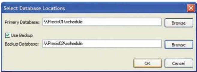
Fig 13-3: Selecting Database Locations
Enter the location of the primary database or use the browse button to search the local PC or the network.
If you are also using a backup recording and archiving system check the 'Use Backup' option and browse for the location of the backup database.
13 Net-Log Scheduler
Create a New Event
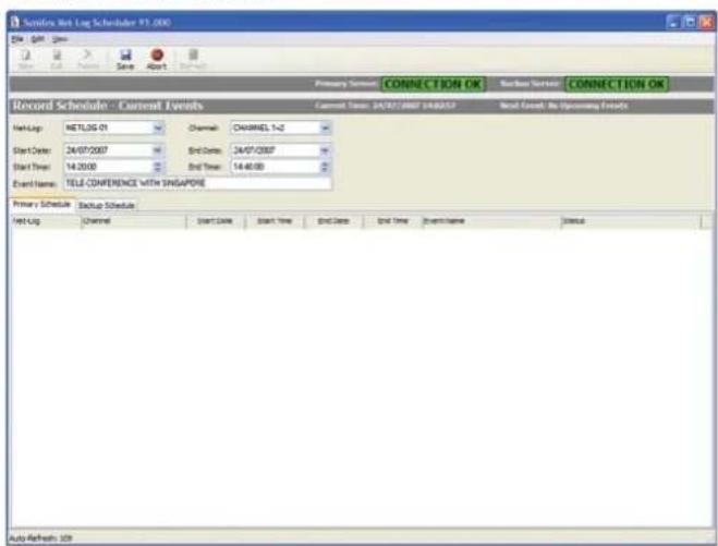
Fig 13-4: Entering a New Schedule Recording
To schedule a new recording, click on the 'New' button or select 'File->New' from the menu.
Select the appropriate Net-Log and Channel to record, and enter the correct start date/time, end date/time and give the recording a meaningful name.
After pressing the 'Save' button on the toolbar, the schedule listing will be updated with the new event.
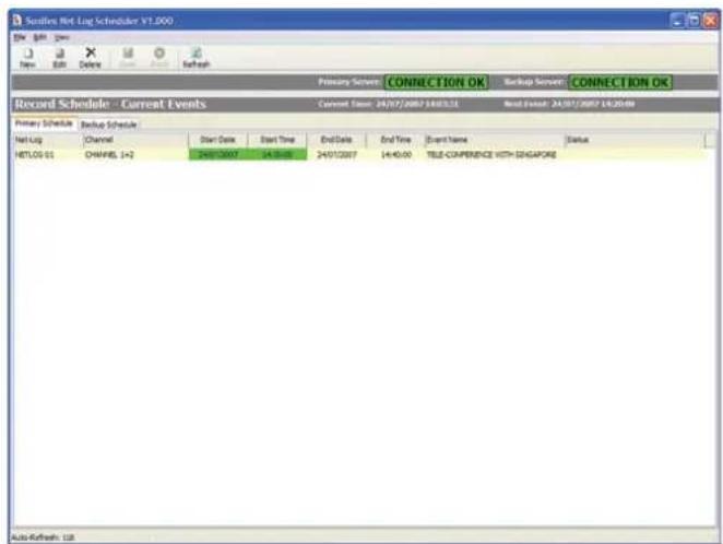
Fig 13-5: Updated Listings with a New Recording
Once a number of recordings have been scheduled, the list can be sorted by clicking on the column headings. The date/time of the next start/stop event is highlighted in green.
Once a scheduled event has expired (passed the stop date/time) the event is low-lighted. After seven days, the item is removed from the Current Events list and is place in a Historic Events list. The lists can be viewed by selecting the appropriate item from the 'View' menu.
There is no limit to the number of recordings that can be scheduled. Although, it is recommended that events are manually deleted from the Historic Events list periodically to ensure system stability.
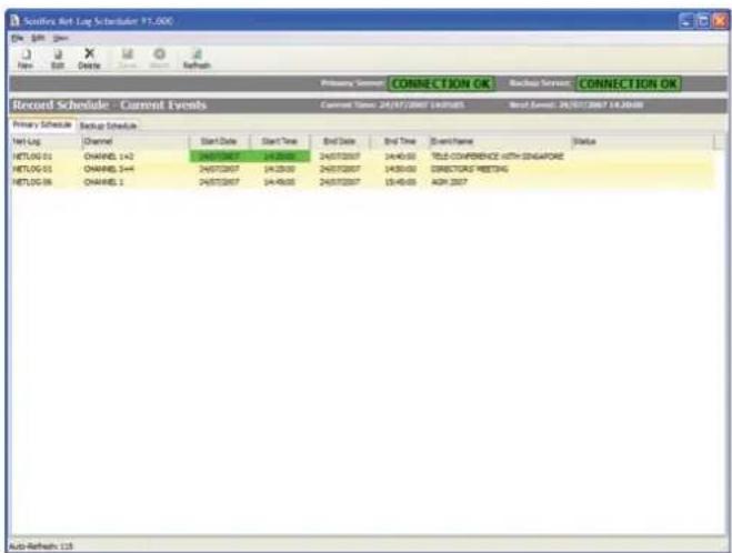
Fig 13-6: A Schedule List Showing Multiple Recordings
Refreshing the Schedules
The primary and backup schedules automatically refresh every 2 minutes. To force a refreshed view of the schedules, press the "REFRESH" button.
14 Technical Specification
14. Technical Specification
Physical Specification
External Dimensions: 1U 19" rack X 220mm deep
Net Weight: 2.5kg
Gross Weight: 3.5kg
Audio Specification
Input Impedance: >10kΩ balanced
Input Gain Range: -6dBu to +20dBu ref. full scale digits
Maximum Input Level: +20dBu
Distortion: <0.1% @ 1kHz +16dBu
Signal To Noise Ratio: 90 dB RMS a wtd. 22kHz bandwidth
Wow and Flutter: Un-measurable
Phase Error at 10kHz: Un-measurable
Please note that the audio specification of the play output depends on the soundcard that you have installed in your PC. Net-Log is a recording device and has no audio output of its own.
Rear Panel Connections, Controls and Indicators
Analogue Inputs (4): XLR 3 Pin socket
Input Level Controls (4): Rotary pre-set potentiometers
Network: RJ45 (10BaseT) and BNC (10Base2)
10Mbps Ethernet
Network Status LED's: Rx, Tx, link and collision
RS232 (2): 9 way D-type plug
Alarm Outputs and
Remote Inputs/Outputs: 15 way D-type plug
Power: IEC Power Plug, 95-265 VAC, 47-63Hz, peak 60W, 30W average
Front Panel Controls and Indicators
Controls: Record control to instantly start recording
Alarm Indicators (2): Disk drive alarm, archive alarm
Level Indicators (4): Analogue input level for each indicator
Additional Information
Audio Formats: MPEG layer 2, G.729A
Sample Rates: MPEG: 16kHz, 22.05kHz, 24kHz, 32kHz, 44.1kHz and 48kHz G.729A: fixed at 8kHz
Recording Types: MPEG: Stereo, Dual Mono, Mono G.729A: Dual Mono, Mono
Minimum PC Specification
Pentium 166MHz, 64MB RAM, Windows compatible Sound card (capable of playing PCM files) & speakers, 10Mbps network connection, Windows XP, 7, 8 or 10, DirectX 6 or greater.
Real Time Clock Accuracy: 1.53 minutes per month.
Hard Disk Capacity: A minimum hard-disk size of 1TB is fitted. Due to the rapidly increase of disk capacities, the actual hard disk installed may be larger than this.
The following tables show the capacity in duration for the different record formats. If more than one channel is used then the duration will need to be shared.
MP2 Record Data Rates
| MPEG Data Rate in Record Duration per kilobits per second (kbps) Gigabyte of Hard Disk Space |
| 8 11d 13h 46m |
| 16 5d 18h 53m |
| 24 3d 20h 35m |
| 32 2d 21h 26m |
| 40 2d 7h 33m |
| 48 1d 22h 17m |
| 56 1d 15h 40m |
| 64 1d 10h 43m |
| 80 1d 3h 46m |
| 96 23h 8m |
| 112 19h 50m |
| 128 17h 22m |
| 144 15h 25m |
| 160 13h 53m |
| 192 11h 34m |
| 224 9h 55m |
| 256 8h 41m |
| 320 6h 56m |
| 384 5h 47m |
G.729A Data Rate in kilobits Record Duration per Gigabyte of per second (kbps) Hard Disk Space
9.6 (fixed)
9d 15h 28m
MP3 Data Rates Supported For Play Download
The selectable mp3 bit rates for Play Download in Net-Log-Win are dependant on the sample rate of the original recording as follows:
| Original Sample Rate: | Available Bit-Rates: |
| 16kHz, 22kHz & 24kHz | 32 kbps, 40 kbps, 48 kbps, 56 kbps, 64 kbps, 80 kbps, 96 kbps, 112 kbps, 128 kbps or 160 kbps |
| 32kHz, 44.1kHz & 48kHz | 32 kbps, 40 kbps, 48 kbps, 56 kbps, 64 kbps, 80 kbps, 96 kbps, 112 kbps, 128 kbps, 160 kbps, 192 kbps, 224 kbps, 256 kbps or 320kbps |
Pin Connections
| COM 1/2 (9 Pin D-Type Plug): | |||
| Pin No. | Signal | Direction | Description |
| 1 | CD | I | Carrier Detect |
| 2 | Rx | I | Receive Data |
| 3 | Tx | O | Transmit Data |
| 4 | DTR | O | Data Terminal Ready |
| 5 | SG | - | Signal Ground |
| 6 | DSR | I | Data Set Ready |
| 7 | RTS | O | Request To Send |
| 8 | CTS | I | Clear To Send |
| 9 | N/C | - | No Connection |
14 Technical Specification
| Network Connector (RJ45): | |||
| Pin No. | Signal Direction | Description | |
| 1 Tx+ O | Transmit Data | (Positive) | |
| 2 Tx- O | Transmit Data | (Negative) | |
| 3 Rx+ I | Receive Data | (Positive) | |
| 4 N/C - No Connection | |||
| 5 N/C - No Connection | |||
| 6 Rx- I | Receive Data | (Negative) | |
| 7 N/C - No Connection | |||
| 8 N/C - No Connection | |||
| Network Connector (BNC Socket): | |||
| Pin No. | Signal Direction | Description | |
| 1 Rx I Receive Data | |||
| 2 Tx O Transmit Data | |||
| Audio Inputs (XLR Socket): | |||
| Pin No. | Signal Direction | Description | |
| 1 | S | - | Screen |
| 2 | P | I | Phase |
| 3 | NP | I | Non-Phase |
| Alarm Outputs/Remote Inputs And Outputs (15 Pin D-Type Plug): | |||
| Pin No. | Signal | Direction | Description |
| 1 | Relay Common | O Alarm | Output Relay Common |
| 2 | Relay N/C | O | Alarm Output Relay N/C to Pin 1activates for both Archive and Hard Disk Alarms |
| 3 | Relay N/O | O | Alarm Output Relay N/O to Pin 1activates for both Archive and Hard Disk Alarms |
| 4 | Relay Common | O Alarm | Output Relay Common |
| 5 | Relay N/C | O | Alarm Output Relay N/C to Pin 4activates for both Archive and Hard Disk Alarms |
| 6 | Relay N/O | O | Alarm Output Relay N/O to Pin 4activates for both Archive and Hard Disk Alarms |
| 7 | GND | - | Ground |
| 8 | REMOTE_11 | I | Remote Input 1 short to Ground(Remote record Channel 1, Left input 1). Set to momentary or latching action via the Options, Record Remotes screen. |
| 9 | REMOTE_12 | I | Remote Input 2 short to Ground (Remote record Channel 2, Right input 1) Set to momentary or latching action via the Options, Record Remotes screen. |
| 10 | REMOTE_13 | I | Remote Input 3 short to Ground (Remote record Channel 3, Left input 2) Set to momentary or latching action via the Options, Record Remotes screen. |
| 11 | REMOTE_14 | I | Remote Input 4 short to Ground (Remote record Channel 4, Right input 2) Set to momentary or latching action via the Options, Record Remotes screen. |
| 12 | REMOTE_O1 | O | Record Tally Output 1. Open collector driver (Channel 1, Left input 1) |
| 13 | REMOTE_O2 | O | Record Tally Output 2. Open collector driver Channel 2, Right input 1) |
| 14 | REMOTE_O3 | O | Record Tally Output 3. Open collector driver (Channel 3, Left input 2) |
| 15 | REMOTE_O4 | O | Record Tally Output 4. Open collector driver (Channel 4, Right input 2) |
15 Glossary
15. Glossary
10Base2 Coaxial, Thin Ethernet. The 10 indicates a transfer rate of 10 Mbps. Base indicates a baseband medium and the 2 indicates that the sections must be a maximum of 200 meters.
10BaseT RJ45, Twisted Pair Ethernet. The 10 indicates a transfer rate of 10 Mbps Base indicates a baseband medium and the T indicates twisted pair wiring.
Bit Rate The raw speed of data over a serial link. Depending on the type of link this may indicate the theoretical maximum rates e.g. 10BaseT sends packets of data at 10Mbps but due to overheads and the availability the actual data throughput is significantly less. For audio data rates the bitrate is the actual amount of data generated per second
Channel Audio signal that generates a single audio stream. The signal can be either mono or stereo but will still be treated a single channel. If the Net-Log is formatted to use dual mono then this is considered as providing 2 channels. If both audio inputs are formatted as dual mono then a total of 4 channels will be available.
Client A node on the network that receives services from a server.
Collision (CI) This occurs when two different nodes attempt to use the network at the same time.
Cut A single continuous piece of audio, either stereo or mono, recorded on the hard drive
dB (decibel) A ratio of two voltages or signal levels, expressed by the equation
dB = 20LOG(V1/V2)
Adding the suffix "u" denotes that the signal is relative
to 0.775V RMS
Adding the suffix "v" denotes that the signal is relative
to 1V RMS
DHCP Dynamic Host Configuration Protocol; Hosts are given
configuration information across a network, usually from
a server.
DNS Domain Name System; TCP/IP applications resolve a
name into an IP Address
G.729A High compression record format primarily designed for
The Ground Truth image displays a single, solid horizontal line. According to Rule 2 (UNDERSCORE & LINE RULES), this is a stylistic or background line, not a placeholder underscore. Therefore, the OCR result must ignore it and output nothing or only meaningful text. The provided OCR content is "____", which consists of four underscores. This is an incorrect interpretation of the line as a placeholder, violating the rule that stylistic lines must be ignored. The OCR has hallucinated underscores where none should exist based on the GT's visual context. Hence, the OCR result is inconsistent with the Ground Truth.
Gain The degree of amplification, or attenuation, applied to a
signal.
Gateway A router that links one network to another.
Gigabyte 1000 million bytes of data storage for a disk drive or
or GB 1073 million bytes of
data storage for memory (i.e. 1024 x 1024 x 1024 bytes)
Host ID The part of the IP Address identifying the node within
the network.
Hub A device used to connect nodes together to form a
network.
IP Address Internet Protocol Address; A 32-bit address used to
locate a node on a network.
kbps Acronym for kilo (thousand) bits per second
LED Light Emitting Diode.
Link A connection to a network.
Mbps Acronym for Mega (million) bits per second
MPEG Acronym for Motion Picture Experts Group who were responsible for the initial audio compression specification
NetworkID The part of the IP Address identifying the address of the local network.
NIC Network Interface Card; A card placed in a PC or Device used to connect to a network.
Node A device connected to a network, usually a PC or Printer.
Octet Eight bits. There are four octets in an IP Address.
Rx Shorthand for Receiver
Sample Rate The frequency at which the incoming audio is sampled. The higher the sample rate the higher the frequency of the audio that will be captured.
Subnet Mask A mask address to determine the NetworkID and HostID contained in an IP Address.
Switch An intelligent hub.
TCP/IP Transmission Control Protocol/Internet Protocol;
THD The Total Harmonic Distortion is the percentage presence of signals outside the measured frequency range.
Tx Shorthand for Transmitter
UTC Acronym for Universal Time Code which is an internet reference time based on Greenwich Mean Time
UTP Acronym for Unshielded Twisted Pair which is the description of the type of cable normally used networking or phone connections
Notes
Notes
SONIFEX
www.sonifex.co.uk
t:+44 (0)1933 650 700
f:+44 (0)1933 650 726
sales@sonifex.co.uk
- Net-Log Handbook
- For the latest Sonifex handbook information please visit the Sonifex website at www.sonifex.co.uk
- Contents
- Playing & Downloading 25
- Archiving 30
- Format of Archived Files
- Serial Control Interface
- Televic CE2500 Protocol 35
- AMX/Crestron Interface 37
- Options 39
- Archive Options 40
- Play Options 41
- Play Program Defaults: 42
- Figures
- SONIFEX
- Register Online for an Extended 2 Year Warranty
- Product Warranty - 2 Year Extended
- Sonifex Warranty & Liability Terms & Conditions
- Definitions
- Warranty
- Warranty
- Unpacking Your Product
- Repairs & Returns
- CE Conformity
- Safety & Installation of Mains Operated Equipment
- Voltage Setting Checks
- Fuse Rating
- Power Cable & Connection
- Safety & Installation
- WEEE Directive
- Atmosphere/Environment
- Introduction
- General Overview
- The Net-Log
- Introduction
- Net-Log Control Software
- Recording
- Playing
- Archiving
- Network
- Required Hardware
- Net-Log Hardware
- Physical Description
- Power
- Level Indicators
- Net-Log Hardware
- Record Control/Indicator
- Archive Alarm
- Disk Drive Alarm
- Reset Switch
- Audio Inputs/Input Level Control
- Network Status Indicators
- Network Connections
- RS232 Serial Ports
- Alarm Outputs And Remote Inputs And Outputs
- Set-up & Installation
- Set-up & Installation
- Adjusting Record Input Levels
- Network Topology
- Maximum Network Connections
- Connecting Net-Log To Your Network
- IP Addresses
- Subnet Masks
- Installing Net-Log-Win Software
- Entering Network Settings
- Startup & Login
- Startup & Login
- Starting Net-Log-Win
- Maximum Concurrent Users
- Multiple Net-Logs On A Network
- Licensing Your Net-Log
- Obtaining License Codes
- The Login Procedure
- The Device List Editor
- First Time Use of Net-Log
- Changing User Details
- General Screen Layout
- Disconnect/Log-Off Button
- Net-Log Selector
- Alarm Indicators
- Network Activity Indicators
- Net-Log & PC Time
- Status Bar
- Screen Selection Buttons
- Mentor Status Indicator
- Recording
- The Record Screen
- Manual Recording
- Program Recording
- Auto Recording
- Remote Recording
- Serial Recording
- Recording
- Saving and Loading Record Programs
- Record Tally Outputs
- Playing & Downloading
- Track List Display
- Play Download
- Playing & Downloading
- Play Program
- Play Stream
- Play File
- Archiving
- Archiving
- The Archiving Process
- Configuring Archival To A Networked PC
- Alarm Enabled
- Buffer Size
- Warn Time
- Arrange Archive Audio into Fixed Duration Files
- Target File Duration
- File Type
- Destination IP Address
- Target Folder Share Name
- Auto Purge on Record Stop Enabled
- Beginning to Archive
- Televic CE2500 Interface
- Serial Control Interface
- Disabled
- Single Mic
- Mic Range
- Televic CE2500 Protocol
- The serial settings on Net-Log for the Televic CE2500 interface are as follows:
- System Synchronisation
- President Microphone Activation
- President Microphone Deactivation
- Delegate Microphone Activation
- Delegate Microphone Deactivation
- Deactivate All Microphones
- System Reset (Deactivate All Microphones)
- AMX/Crestron Interface
- AMX/Crestron Protocol
- Speed of Commands & Responses:
- Record Start Command
- Record Stop Command
- Status Command
- Time Command
- Date Command
- Reply Error Codes
- Options
- Saving and Loading Options
- Record Options
- Disable
- Override Enabled
- Format
- Options
- Mode
- Channels
- Sample Rate & Bit Rate
- Start Level
- Start Duration
- Stop Level
- Stop Duration
- Service Names
- Note that once recording has started on a channel, the record format cannot be changed until recording has stopped and all track(s) have been deleted.
- Record Capacity
- Archive Options
- Buffer Size (Mbytes)
- Target File Type
- Archive Auto Continue Enabled
- Play Options
- Use Defaults
- Default Play Screen
- Play Download Defaults:
- Folder
- File Type and Bit Rate
- Play Program Defaults:
- Play Stream Defaults:
- Play File Defaults:
- Remotes Options
- Momentary
- Latching
- Normally Off, Switched On For Alarm Condition
- Clock Source Options
- Control Options
- No Control/Interface Selected
- Televic CE2500
- AMX/Crestron
- Net-Log-Win Options
- Info Font
- User Font
- Information
- The Administrator
- TheAdministrator
- Licenses
- Accounts Editor
- Function Access - View
- Function Access - Control
- User Name & Password
- The Onboard Clock
- Updating The Onboard Clock
- Network Settings
- Updating Firmware
- Resetting The Net-Log
- Tools
- Show Cut List
- Auto Refresh Cut Display
- Play Cut Auto Load
- Hide Unavailable Cuts
- Suspend Play Programs
- Log Play Program Operation
- Deleting Cuts
- View
- Net-Log Connections
- Tools
- Net-Log Status
- Drive Alarm
- Cut Change
- Program Change
- Config Change
- Record Auto Enabled
- Record Active
- Archive Enabled
- Archive Pending
- Archive Auto Purge
- Archive Active
- Archive Warn
- Network Stats
- Audio Header Info
- Play Program Log
- About Sonifex Net-Log
- Auto-Archive
- Introduction
- Licensing
- The Net-Log List
- The Status Bar
- Auto-Archive
- Performance
- System Set-up
- Starting The Archive
- The Settings Screen
- Device List
- System Name
- Force Record Stop at Midnight
- Auto-Delete Archives
- Use mm-dd-yyyy Format for Archive Folders
- The Status Screen
- The Control Screen
- The Archive Screen
- The Event Log Screen
- Reports
- Status Report
- Error Report
- Possible Errors
- Archive Warn Report
- Archive Alarm Report
- Startup/ Shutdown
- The Schedule
- The Schedule Database
- Network Scheduling
- The Schedule Screen
- Net-Log Scheduler
- 13.Net-Log Scheduler
- Database Connection Status
- Primary and Backup Schedules
- Database Locations
- Refreshing the Schedules
- Technical Specification
- Technical Specification
- Physical Specification
- Audio Specification
- Rear Panel Connections, Controls and Indicators
- Alarm Outputs and
- Front Panel Controls and Indicators
- Additional Information
- Minimum PC Specification
- MP3 Data Rates Supported For Play Download
- Glossary
- Glossary
Brand : Sonifex
Model : NET-LOG
Category : Media player