
Digital Performer 10 - Audio software MOTU - Free user manual and instructions
Find the device manual for free Digital Performer 10 MOTU in PDF.


| Type of product | Digital Audio Workstation (DAW) software |
| Version | Digital Performer 10 |
| Developer | MOTU (Mark of the Unicorn) |
| Operating systems | macOS and Windows |
| Supported audio interfaces | Core Audio (Mac), ASIO (Windows), MOTU hardware |
| Audio file formats | AIFF, WAV (16, 24, 32-bit float), Broadcast WAV, interleaved/deinterleaved |
| Sample rates | Up to 192 kHz (depending on hardware) |
| Bit depths | 16, 24, 32-bit floating point |
| MIDI capabilities | Recording, editing, step recording, MIDI effects, SysEx |
| Number of tracks | Unlimited (limited by system resources) |
| Track types | Audio, MIDI, instrument, aux, master fader, VCA, group, folder |
| Audio effects | MAS, VST, Audio Units (AU) support; included effects: EQ, dynamics, reverb, delay, modulation, spectral |
| Virtual instruments | Included: Model 12, Bass, PolySynth, etc.; supports VSTi and AUi |
| Automation | Breakpoint automation for volume, pan, plug-in parameters; snapshot automation |
| Synchronization | MTC, MIDI beat clocks, sample-accurate sync (with compatible hardware), SMPTE, word clock |
| File interchange | OMF, AAF, MIDI file (Type 0/1), Final Cut Pro XML, MusicXML |
| Notation editor | QuickScribe Editor with printing and MusicXML export |
| Bouncing / mastering | Bounce to disk (WAV, AIFF, MP3, CD image), offline and real-time |
| Recording modes | Cycle record, punch-in/out, over-dub, take comping, POLAR loop recorder |
| User interface | Consolidated window, customizable window sets, themes, track colors |
| Plug-in formats | MAS (native), VST, Audio Units (AU) |
| Surround sound | Up to 10.2 channels, surround panner, binaural monitoring |
| Control surface support | Mackie Control, HUI, OSC devices, MIDI controllers |
| Minimum system requirements | Intel or Apple Silicon Mac / multi-core PC; 4 GB RAM (8+ GB recommended); 1 GB disk space for installation |
Frequently Asked Questions - Digital Performer 10 MOTU
User questions about Digital Performer 10 MOTU
0 question about this device. Answer the ones you know or ask your own.
Ask a new question about this device
Download the instructions for your Audio software in PDF format for free! Find your manual Digital Performer 10 - MOTU and take your electronic device back in hand. On this page are published all the documents necessary for the use of your device. Digital Performer 10 by MOTU.
USER MANUAL Digital Performer 10 MOTU
1280 Massachusetts Avenue
Cambridge, MA 02138
Business voice: (617) 576-2760
Business fax: (617) 576-3609
Technical support: (617) 576-3066
Tech support web: www.motu.com/support
Web site: www.motu.com
ABOUT THE MARK OF THE UNICORN LICENSE AGREEMENT AND LIMITED WARRANTY ON SOFTWARE
TO PERSONS WHO PURCHASE OR USE THIS PRODUCT: carefully read all the terms and conditions of the "click-wrap" license agreement presented to you when you install the software. Using the software or this documentation indicates your acceptance of the terms and conditions of that license agreement.
Mark of the Unicorn, Inc. ("MOTU") owns both this program and its documentation. Both the program and the documentation are protected under applicable copyright, trademark, and trade-secret laws. Your right to use the program and the documentation are limited to the terms and conditions described in the license agreement.
REMINDER OF THE TERMS OF YOUR LICENSE
This summary is not your license agreement, just a reminder of its terms. The actual license can be read and printed by running the installation program for the software. That license agreement is a contract, and clicking "Accept" binds you and MOTU to all its terms and conditions. In the event anything contained in this summary is incomplete or in conflict with the actual click-wrap license agreement, the terms of the click-wrap agreement prevail.
YOU MAY: (a) use the enclosed program on a single computer; (b) physically transfer the program from one computer to another provided that the program is used on only one computer at a time and that you remove any copies of the program from the computer from which the program is being transferred; (c) make copies of the program solely for backup purposes. You must reproduce and include the copyright notice on a label on any backup copy.
YOU MAY NOT: (a) distribute copies of the program or the documentation to others; (b) rent, lease or grant sublicenses or other rights to the program; (c) provide use of the program in a computer service business, network, time-sharing, multiple CPU or multiple user arrangement without the prior written consent of MOTU; (d) translate, adapt, reverse engineer, decompile, disassemble, or otherwise alter the program or related documentation without the prior written consent of MOTU.
MOTU warrants to the original licensee that the disk(s) on which the program is recorded be free from defects in materials and workmanship under normal use for a period of ninety (90) days from the date of purchase as evidenced by a copy of your receipt. If failure of the disk has resulted from accident, abuse or misapplication of the product, then MOTU shall have no responsibility to replace the disk(s) under this Limited Warranty.
THIS LIMITED WARRANTY AND RIGHT OF REPLACEMENT IS IN LIEU OF, AND YOU HEREBY WAIVE, ANY AND ALL OTHER WARRANTIES, BOTH EXPRESS AND IMPLIED, INCLUDING BUT NOT LIMITED TO WARRANTIES OF MERCHANTABILITY AND FITNESS FOR A PARTICULAR PURPOSE. THE LIABILITY OF MOTU PURSUANT TO THIS LIMITED WARRANTY SHALL BE LIMITED TO THE REPLACEMENT OF THE DEFECTIVE DISK(S), AND IN NO EVENT SHALL MOTU OR ITS SUPPLIERS, LICENSORS, OR AFFILIATES BE LIABLE FOR INCIDENTAL OR CONSEQUENTIAL DAMAGES, INCLUDING BUT NOT LIMITED TO LOSS OF USE, LOSS OF PROFITS, LOSS OF DATA OR DATA BEING RENDERED INACCURATE, OR LOSSES SUSTAINED BY THIRD PARTIES EVEN IF MOTU HAS BEEN ADVISED OF THE POSSIBILITY OF SUCH DAMAGES. THIS WARRANTY GIVES YOU SPECIFIC LEGAL RIGHTS WHICH MAY VARY FROM STATE TO STATE. SOME STATES DO NOT ALLOW THE LIMITATION OR EXCLUSION OF LIABILITY FOR CONSEQUENTIAL DAMAGES, SO THE ABOVE LIMITATION MAY NOT APPLY TO YOU.
UPDATE POLICY
In order to be eligible to obtain updates of the program, you must visit motu.com/registration and complete the on-line product registration form (or complete and return to MOTU the Competitive Upgrade envelope if you have purchased a Competitive Upgrade).
COPYRIGHT NOTICE
Copyright ©2020, 2019, 2018, 2017, 2016, 2015, 2014, 2013, 2012, 2011, 2010, 2009, 2008, 2007, 2006, 2005, 2004, 2003, 2002, 2001, 2000, 1999, 1998, 1997, 1996, 1995, 1994, 1993, 1992, 1991 by Mark of the Unicorn, Inc. All rights reserved. No part of this publication may be reproduced, transmitted, transcribed, stored in a retrieval system, or translated into any human or computer language, in any form or by any means whatsoever, without express written permission of Mark of the Unicorn, Inc., 1280 Massachusetts Avenue, Cambridge, MA, 02138, U.S.A.
Digital Performer, MOTU, Mark of the Unicom and the unicorn silhouette logo are trademarks of Mark of the Unicom, Inc.
ZTX Time Stretch/Pitch Shift technology licensed from Zynaptiq GmbH (http://www.zynaptiq.com). © Zynaptiq GmbH.
MPEG LICENSE
Supply of this product does not convey a license nor imply any right to distribute MPEG Layer-3 compliant content created with this product in revenue-generating broadcast systems (terrestrial, satellite, cable and/or other distribution channels), streaming applications (via Internet, intranets and/or other networks), other content distribution systems (pay-audio or audio-on-demand applications and the like) or on physical media (compact discs, digital versatile discs, semiconductor chips, hard drives, memory cards and the like). An independent license for such use is required. For details, please visit http://mp3licensing.com.
Contents at a Glance
Part 1: Managing Projects
23 The Digital Performer Project
33 Import and Export
41 Soundbites Window
55 Content Browser
57 Audio File Management
61 Project File Interchange
Part 2: Customizing Your Workspace
77 Preferences and Settings
99 Time Formats and Display
105 Commands
109 Consolidated Window
119 Window Sets
Part 3: Sequences and Tracks
123 Sequence Basics
125 Track Basics
131 Bundles
139 MIDI Tracks
147 Audio Tracks
155 Instrument Tracks
159 Aux Tracks and Master Fader Tracks
163 VCA Tracks
169 Tracks Window
187 Track Folders and Track Groups
Part 4: Playing and Recording
195 Control Panel
221 Playback
231 Recording
255 Click and Countoff
263 MIDI Monitor
265 Audio Monitor
271 Step Record
283 Retrospective MIDI Record
287 Clips Window
299 POLAR
311 Movie Window
319 ReWire
Part 5: Editing
325 Editing Basics
339 Edit Windows
347 Tools
355 Information Windows
371 Sequence Editor
411 MIDI Editor
437 Event List
451 Drum Editor
473 Notation Editor
479 QuickScribe Editor
525 Waveform Editor
547 Selecting
561 Searching
573 Edit Menu
593 Region Menu
645 Audio Menu
657 Fades and Crossfades
665 Takes and Comping
673 Tempos and Audio
681 Audio Beats and Tempo Detection
697 System Exclusive
705 Clippings
711 Custom Consoles
Part 6: Arranging
733 Conductor Track
741 Change Tempo
749 Change Meter
755 Change Key
759 Insert Measures
761 Adjust Beats
765 Record Beats
771 Markers
781 Find Tempo
787 Streamers, Punches and Flutters
793 Chunks Window
803 V-Racks
809 Songs
Part 7: Mixing
821 Mixing Board
851 Mix Automation
871 Mixing in Surround
885 Meter Bridge
Part 8: Processing
891 Effects Window
897 Audio Effects Processing
911 MIDI Effects Processing
919 Audio File Conversion
921 Time-stretching and pitch-shifting
927 Background Processing
931 Spectral Effects
935 Transposing Audio
947 Scale Time
949 VocAlign
Part 9: Mastering
953 Bounce To Disk
971 Mastering
Part 10: Synchronization
977 Receive Sync
995 Audio Sync
1001 Transmit Sync
1005 MIDI Machine Control
Part 11: Appendices
1015 Control Surfaces
1019 Troubleshooting and Support
1025 Menus reference
1049 Index
Contents
Part 1: Managing Projects
23 The Digital Performer Project
23 Overview
23 Components of a DP Project
24 Creating a new project
24 Creating a new project with Create Tracks
25 Creating a new project from a template
25 Opening an existing project
25 Open Recent sub-menu
25 Saving a project
25 Saving a project file under a different name
26 Save a Copy As
26 Using Save a Copy As for incremental backups
26 Autosave
26 Collecting a project for backup or transfer
27 Avoiding disaster
27 Importing files in other formats
27 Exporting a project
27 Moving a project between Mac and Windows
27 Interchanging with Final Cut Pro XML
27 Exporting to notation software through MusicXML
28 Reverting to a previously saved project
28 Creating project templates
29 Loading a sequence, song or V-Rack
30 Adding project notes
30 Printing project windows
31 Closing a project
31 Quitting/Exiting Digital Performer
32 Setting Digital Performer's startup preferences
32 Helpful project and disk hints
33 Import and Export
33 Overview
33 Importing project files in other formats
33 Exporting a project
35 Exporting selections
36 Interchanging with Final Cut Pro XML
36 Importing and exporting audio
40 Bouncing audio files
41 Soundbites Window
41 Overview
41 Quick Reference
42 Soundbites window mini-menu
43 Opening the Soundbites window
43 The Soundbite list
47 Soundbite Basics
47 Mono, stereo and multi-channel audio
47 Importing and exporting audio
47 Soundbite Management
51 Dragging and dropping soundbites
52 Working with multiple sample formats
52 Converting sample rate/format
52 Automatic conversions
53 Reload Soundbite
53 Replace Soundbite
53 Edit in Waveform Editor
53 Use external waveform editor
53 Viewing more Sound File Information
55 Content Browser
55 Overview
55 Quick Reference
56 Content Browser mini-menu
56 Opening the Content Browser
56 Using the Content Browser
56 Auditioning audio clips
57 Audio File Management
57 Overview
57 The Audio Files folder
57 Renaming audio files
57 Moving audio files
57 Working with multiple drives
57 Deleting audio files
58 Getting rid of unused audio
60 Compacting an entire project
61 Project File Interchange
61 Overview
61 Introduction to OMF and AAF
61 Importing OMF/AAF files
62 Exporting OMF/AAF files
67 Final Cut Pro XML interchange
Part 2: Customizing Your Workspace
77 Preferences and Settings
77 Overview
77 The Preferences window
78 Audio Files
79 Audio Plug-ins
79 Background Processing
79 Document
80 Run Command Window
80 Shortcuts
81 Consolidated Window
81 Control Panel
81 Data Display
83 Scrolling and zooming
83 Themes
84 Track colors
89 Automatic Conversions
90 Chord Symbols
90 Clippings
90 Continuous Data
91 Edit Windows
91 Information Bar
91 Lyrics
92 MIDI Editing
93 Region Commands
93 Soundbite List
93 Tools
93 Tracks List
94 Tracks Overview
94 Undo Pruning
94 Waveform Editor
94 Audio Options
95 Click
95 Click Defaults
95 Countoff
95 Film Scoring Events
95 MIDI Options
95 Pitch and Stretch
96 Receive Sync
96 Transmit Sync
96 Transport
96 Scaling all windows up or down
96 Help menu
99 Time Formats and Display
99 Overview
99 Specification of time formats
100 Time Formats window
103 Setting the start time
105 Commands
105 Overview
105 Opening the commands window
105 Navigating the commands window
106 Command groups
106 MIDI Masters
106 Assignments
107 Numeric Base note
107 Chunk remote assignment
107 Run command
108 Export Key Bindings
108 Import Key Bindings
109 Consolidated Window
109 Overview
110 Quick Reference
111 Window menu
111 Deciding how to work with windows
112 Consolidated Window preferences
113 Opening the Consolidated Window
114 Going full screen
114 Consolidated Window title bar
114 Other window Title bars
114 The Control Panel
114 The body (center) section
114 The Sidebars
115 The Mixing Board
116 Using Horizontal Dividers
116 Dragging cells
116 Cell focus
117 Getting rid of a cell
117 Popping windows in and out
117 The Consolidated Window and Window Sets
118 Opening old documents
119 Window Sets
119 Overview
119 Creating a new window set
119 Choosing a window set
119 Changing an existing window set
119 Otherwise modifying window sets
120 Window set tips and tricks
Part 3: Sequences and Tracks
123 Sequence Basics
123 Overview
123 Chunk types
123 Managing sequences, V-racks and songs
125 Track Basics
125 Overview
125 Basic track types
126 Special track types
126 Track settings
129 Creating a track
129 Creating several tracks at once
129 Creating multiple track types at once
129 Duplicating a track's settings
129 Duplicating a track's settings and data
130 Renaming a track
130 Deleting a track
131 Bundles
131 Overview
131 Audio bundles
132 Bundle types
132 Adding and deleting bundles
132 Renaming bundles
133 Working with tiles on the grid
133 Exporting and importing bundles
133 Bundle channel formats
134 Reassigning bundles
135 Bundles and surround sound
135 The instruments tab
136 The MIDI Devices tab
139 MIDI Tracks
139 Overview
139 Integrated MIDI and hard disk audio
139 MIDI only
139 What is a MIDI track?
139 Creating a MIDI track
139 Creating several MIDI tracks at once
140 MIDI track settings
140 Record-enabling a MIDI track
140 Choosing an input source
140 Choosing a MIDI output destination
141 Making I/O assignments for multiple MIDI tracks
141 Multiple output destinations
142 Creating a MIDI device group
143 MIDI Drum & percussion tracks
143 Remap MIDI Devices
143 Choosing a default patch (sound)
143 The patch list
143 The current patch
144 MIDI Keys
147 Audio Tracks
147 Overview
147 Integrated MIDI and hard disk audio
147 Types of audio tracks
147 Audio (disk) tracks
147 Mono, stereo, and surround tracks
148 Creating an audio track
148 Creating several audio tracks at once
148 Audio track settings
148 Input source: Audio bundles
149 Choosing an audio input and output
149 Record-enabling an audio track
149 Input monitor enable
149 Stretch
150 Pitch and Stretch Cache
150 Enabled
151 Monitoring an audio track input
151 Changing audio track settings on the fly
151 Making I/O assignments for multiple tracks
152 Managing your computer's system resources
152 Freezing tracks
155 Instrument Tracks
155 Overview
155 Creating an instrument track
156 Instrument track settings
156 Working with instrument plug-ins
157 Instrument tracks in the Mixing Board
157 Open Instrument shortcut
157 Instrument track automation
157 Freezing instrument tracks
157 Instruments as audio plug-ins
157 Instrument plug-ins in V-Racks
158 Multiple audio outputs
158 Digital Performer's included instruments
159 Aux Tracks and Master Fader Tracks
159 Overview
159 Aux tracks
160 Master Fader tracks
163 VCA Tracks
163 Overview
163 VCA tracks and track groups
163 Creating a VCA track
164 VCA control
164 Shared tracks and nested VCA groups
165 VCA tracks and mix automation
166 Releasing a VCA track from its group
166 MIDI tracks and VCA tracks
167 Exporting to earlier versions of DP
169 Tracks Window
169 Overview
170 Quick Reference
173 Tracks Window Mini-menu
174 Opening the Tracks window
174 Sequence management in the Tracks window
175 The Marker menu
175 The Track List
179 Working with the Track List
181 The Track Overview
186 Customizing the Tracks Window
187 Track Folders and Track Groups
187 Overview
187 Track Folders
188 Track Groups
Part 4: Playing and Recording
195 Control Panel
195 Overview
196 Quick Reference
198 Control Panel preferences
199 Transport Controls
201 Counter
205 Large Counter
206 Memory buttons
210 Auto-Record
211 Overdub record mode
212 Countoff
212 Wait
212 Slave to External Sync
212 Saving Memory and Auto-Record Times
213 Status Strip
213 Tempo Controls
217 Click
217 Audible Mode
217 Auto Scroll
217 Solo Mode
217 Primary and alternate tools
218 Keypad shortcuts
219 Display Preferences
221 Playback
221 Overview
221 MIDI Playback basics
221 Audio playback basics
221 How to play a sequence or song
222 Monitoring levels
222 Editing during playback
222 Screen re-display
223 Muting and unmuting tracks during playback
223 Soloing Tracks
223 'Partial-solo'
224 Looping playback
224 Playing the current selection
224 Event Chasing
226 Auto scroll
229 Scrubbing multiple MIDI tracks
229 Scrubbing and grid snapping
229 Scrubbing audio
229 Slow and fast forwarding
229 Stop Sounding MIDI Devices (Panic)
231 Recording
231 Overview
232 Choosing a sequence to record into
232 Setting tempo and meter
232 Recording to a click
232 Recording with a Countoff
233 Input Filter
233 Input Quantize
234 Non-destructive output quantize
235 Preparing a MIDI track for recording
236 Preparing an audio track for recording
238 MIDI input monitoring
241 Audio input monitoring
244 Using the wait and countoff features
244 Start recording
244 Stop recording
245 How audio is recorded on disk
245 Undo record
245 Recording stereo audio
245 Recording in surround
245 Recording several MIDI tracks in one pass
246 Recording several audio tracks in one pass
246 Recording audio and MIDI at the same time
246 Manual punch-in/punch-out on the fly
246 Automatic punch-in/punch-out
248 Punch Guard
248 Overdub recording
249 Recording multiple takes
249 Cycle-recording
252 Step Recording
252 Retrospective MIDI Record
252 Recording in External Sync
252 Sample Format
253 Getting an error message
255 Click and Countoff
255 Overview
255 Click
256 Click Preferences
258 Click Defaults
259 Countoff
259 Countoff preferences
263 MIDI Monitor
263 Overview
263 Opening the MIDI Monitor Window
263 Basics
265 Audio Monitor
265 Overview
265 Audio Monitor quick reference
266 Mini-menu quick reference
266 Buses in the Audio Monitor
266 Virtual instrument inputs
267 Naming a takefile before recording
267 Changing the takefile location before recording
268 Adjusting the level meter range
269 Setting the input level
269 Other ways to monitor input levels
271 Step Record
271 Overview
271 Step Record quick reference
272 Basics
272 Getting ready
276 Performing step entry
279 Step recording during playback
279 Step Record shortcuts
282 Be careful
282 Hints
283 Retrospective MIDI Record
283 Overview
283 MIDI input is always being captured
283 Inserting captured material into a MIDI track
284 Retrospective MIDI Record in the Clips Window
285 Retrospective MIDI Record and Multi-Record
285 Retrospective MIDI Record and Input Quantize
285 Retrospective MIDI Record and Undo
287 Clips Window
287 Overview
288 Quick reference
289 Clips window mini-menu
290 What is a clip?
290 Clips versus clippings
290 Opening the Clips window
291 Clips window basics
291 The track Stretch setting
291 Showing, hiding and arranging track columns
291 Track types
291 Track playback versus clip playback
292 Creating clips
293 The trigger button
293 Track clips
293 Clip menu
294 Scenes
294 The track scene
294 Playing clips and scenes
294 The multi-queue
295 Mixer channels
295 The Clip Editor
297 Clip Record mode
297 MIDI Learn Mode
298 Attaching MIDI controllers for mixing
299 POLAR
299 Overview
300 A typical POLAR session
301 Ideas for using POLAR
301 Preparations for using POLAR
302 Opening the POLAR window
302 Memory used
302 Ways to free up RAM for POLAR recording
302 Setting the length of each pass
303 Choosing an input and setting input level
303 Processing POLAR input with effects
303 Recording multiple channels into POLAR
303 Choosing an output
304 Controlling POLAR's output volume
304 Effects processing on output
304 Monitoring POLAR's live audio input
304 The current pass
305 Adjusting levels and panning
305 Playback and transport control
305 Punching in and out
305 Creating new passes
306 The record gate settings
306 Viewing previous passes
306 Working with passes in the pass list
306 Working with pass groups
307 Exporting a POLAR session
308 Saving and loading POLAR sessions
308 Remote control of the POLAR window
311 Movie Window
311 overview
311 Random access digital picture
311 Supported video formats
311 Opening movies
312 Closing movies
313 Movie control bar
313 The movie track
314 Movie window mini-menu commands
315 Scrubbing the Movie window
315 Improving movie window performance
315 External video hardware output
317 FireWire video output
318 Streamers and other visual cues
318 Exporting a Movie
319 ReWire
319 Overview
319 What is ReWire?
319 Setting up ReWire
320 MIDI output
321 Multiple ReWire audio outputs
321 Synchronization and transport control
321 Tempo control
321 Plug-in processing on ReWire synth inputs
321 Renaming ReWire synth inputs
321 Quitting the ReWire synth
Part 5: Editing
325 Editing Basics
325 Overview
325 Unlimited Undo/Redo
325 Editing during playback
325 Selecting and searching
325 Region editing
326 Track groups
326 View menu
328 View Filter
331 Zooming
334 Scroll To
334 Graphic editing techniques
335 Audio editing basics
337 Sample accurate editing
337 Audible mode
339 Edit Windows
339 Overview
339 Edit window overview
341 Edit windows by track type
341 Opening edit windows
342 Viewing multiple tracks in one edit window
343 Viewing the same track in multiple edit windows
343 Window Target
344 Edit Window mini-menus
344 Information windows
344 Legend
344 Related topics for Editor windows
347 Tools
347 Overview
347 Main and Alternate Tools
348 Rotating the Tool palette
348 Palette docking
348 Closing the Tool palette
348 Keyboard shortcuts for tools
349 Pointer tool
349 I-Beam tool
350 Pencil tool
350 Insert/Reshape Curve
350 Reshape tool
350 Reshape Mode menu
351 Rhythm Brush
351 Zoom tool
352 Scrub tool
352 Mute tool
352 Scissors tool
353 Trim tool
354 Roll tool
354 Slip tool
354 Slide tool
354 Comp tool
354 Velocity tool
354 Hand tool
355 Information Windows
355 Snap Information
358 Cursor Information
359 Event Information
359 Selection Information
361 Track Inspector
362 Channel Strip
364 Track Selector
365 Sound File Information
367 Information Bar
371 Sequence Editor
371 Overview
372 Quick Reference
375 Tool palette quick reference
376 Sequence Editor mini-menu
376 Sequence Editor title bar
376 Sequence Editor basics
376 Opening the Sequence Editor
376 Switching sequences
377 Sequence management
377 Track management
378 Snap, Cursor, Selection, and Event Information
378 The Time Ruler
378 The Marker Strip
379 The Memory Cycle Strip
379 The Auto Record Strip
379 Zoom buttons
380 Zooming techniques
380 Audio track settings
385 MIDI track settings
386 Working with MIDI tracks
386 Resizing tracks
387 Effect inserts panel
388 Audio editing basics
389 Inserting soundbites
390 Moving soundbites
392 Muting and unmuting soundbites
393 Bite Gain
393 Overlapping and layering soundbites
393 Trimming (edge editing) soundbites
396 Graphic time stretching of audio
396 Applying fades and crossfades
396 Takes
396 Graphic editing techniques
396 Selection techniques
398 Show times
399 Sync points
400 Working with Clips
403 Working with breakpoint mix automation
407 Soundbite volume automation
407 Working with event flags
408 The View Filter
408 Scrolling during playback
408 Scrubbing in the Sequence Editor
408 The movie track
409 The Conductor track
411 MIDI Editor
411 Overview
412 Quick Reference
414 Tool palette quick reference
415 MIDI Editor mini-menu
415 MIDI Editor title bar
415 MIDI Editor basics
415 Opening the MIDI Editor
415 The Track Selector
416 The master track selector
416 Opening a separate MIDI Editor for each track
416 Switching tracks with the Window Target menu
416 Snap, Cursor, Selection, and Event Information
416 The Time Ruler
417 The Marker Strip
417 The Memory Cycle Strip
417 The Auto Record Strip
417 The Note Grid
418 The Pitch Ruler
419 Inserting Notes
420 Selecting Notes
420 Editing Notes
422 The Continuous Data Grid
422 Three continuous data display modes
423 The Continuous Data Ruler
424 Showing/hiding continuous data types
425 Cont. Data Icons
425 Changing continuous data colors
426 Note velocities
427 Editing continuous data in Points or Bars mode
429 Editing continuous data in Lines mode
431 The Median Strip
433 Zooming
433 Graphic editing techniques
433 The View Filter
433 Scrolling during playback
433 Scrubbing in the MIDI Editor
434 Editing in the Conductor Track
435 Clips in the MIDI Editor
437 Event List
437 Overview
437 Quick Reference
438 Event List mini-menu
438 Event List title bar
438 Event List basics
439 Types of events
439 MIDI Data
443 Audio data
444 Mix automation data
444 Clips and Conductor Track data
445 Inserting data in the Event List
446 Editing data in the Event List
448 Event List hints
451 Drum Editor
451 Overview
452 Quick Reference
455 Tool palette quick reference
455 Drum Editor mini-menu
456 Drum Editor basics
456 Opening the Drum Editor
456 The Drum Editor title bar
456 The Track Selector
456 The Master Track Selector
457 Using the Window Target menu
457 Snap, Cursor, Selection, and Event Information
457 The four drum editor panes
457 The note list
463 The note grid
467 The controller grid and median strip
467 Using the Tool palette in the Drum Editor
470 Note groups
471 Scrolling during playback
471 Scrubbing in the Drum Editor
471 Zooming
471 Graphic editing techniques
473 Notation Editor
473 Overview
474 Notation Editor Quick Reference
475 Notation Editor Mini-menu
475 Notation Editor basics
475 Opening the Notation Editor
475 The Notation Editor title bar
475 Snap, Cursor, Selection, and Event Information
475 Display resolution
476 Octave up/down buttons
476 Inserting, selecting & editing notes
477 Scrubbing in the Notation Editor
478 Zooming in the Notation Editor
478 Graphic editing techniques
479 QuickScribe Editor
479 Overview
480 QuickScribe Editor Quick Reference
481 QuickScribe Editor mini-menu
483 QuickScribe Editor basics
484 Opening the QuickScribe Editor
484 The QuickScribe Editor title bar
484 The Track Selector
484 The QuickScribe transcription engine
485 The playback wiper
485 Getting around in the QuickScribe Editor
486 Zooming
486 QuickScribe options menu
487 Score options
488 Track options
490 Marker options
491 Measure numbers
492 Measure spacing
492 Set Score Length
492 Controlling page size
492 Adjusting system margins
493 Snap, Cursor, Selection, and Event Information
493 The QuickScribe Tool Palette
493 Working with notes
498 Chord Symbols
500 Inserting a staff brace or bracket
500 The Dynamics Palette
501 Popup Meter Changes, key changes and tempos
502 Working with text
506 Lyrics
510 Score Arrangement
515 Display-only and playback-only notes
517 Film Cues view
520 Printing
521 Exporting a musicXML file
525 Waveform Editor
525 Overview
526 Waveform Editor quick reference
527 Tool palette quick reference
528 Waveform editor mini-menu
528 'Destructive' editing
529 Opening the Waveform editor
529 The Waveform Editor title bar
530 Snap, Selection, and Event Information
530 Cursor Information
530 Cursor Guidelines
530 Grid lines
530 Waveform Editor edit grid
531 Edit Layers
531 Transport lock
531 Selection
531 Global time format
531 Undo History
532 The audio file overview
532 The Audio layer
534 Selecting with the I-Beam cursor
535 Making an insertion point
535 Auditioning
536 Scrubbing
536 The Audio Layer menu
536 The Soundbites layer
538 The soundbites Layer menu
538 The Loops Layer
540 The Loops menu
541 Soundbite and loop shortcuts
541 The Pitch layer
541 The Beats layer
541 The Beats menu
541 The Tempos layer
541 The Tempos menu
541 The Stretch Layer
542 The Bite Volume layer
542 Creating a new, empty audio file
542 Creating a new audio file from a selection
542 Edit menu operations
543 Region and Audio menu operations
544 Waveform Editor preferences
547 Selecting
547 Overview
547 Selection basics
548 The View Filter
548 Choosing a Pointer tool selection mode
549 Selecting events
551 Selecting a time range
556 Smart Selections
561 Searching
561 Overview
561 Search window Quick Reference
562 Search window mini-menu
562 Basics
564 Working with search settings
566 The time-related search settings
567 The event-related search settings
568 Working with search results
570 Basing settings on the current selection
570 The Search Results window
573 Edit Menu
573 Overview
573 Undo
573 Redo
574 Redo Next/Select Branch
574 Undo History
580 Cut
580 Copy
581 Copy to Clipping window
581 Paste
582 Paste Multiple
582 Paste Repeat
582 Paste Repeat Multiple
582 Other Paste commands
582 Erase
582 Duplicate
583 Repeat
583 Merge
584 Merge Multiple
584 Merge Together
584 Merge Repeat
584 Merge Repeat Multiple
584 Merge Repeat Together
584 Other Merge commands
585 Snip
585 Splice
585 Splice Multiple
585 Other Splice commands
585 Shift
587 Layering
587 Continuous Data
587 Heal Separation
588 Split
588 Split Audio
588 Split at Counter
589 Trim
589 Trim Audio
589 Trim End / Trim Start
590 Show/Hide Clipboard
590 Search
590 Select All
590 Select All in Range
591 Deselect All
591 Smart Selections
593 Region Menu
593 Overview
593 Region command windows
594 Previewing
594 Region command preferences
594 Transpose
603 Quantize
609 Groove Quantize
615 Create (Extract) Groove
618 Smart Quantize
618 Humanize
621 DeFlam
622 Change Velocity
625 Change Duration
628 Split Notes
631 Invert Pitch
632 MIDI Effects Plug-ins
633 The continuous data commands
634 Thin Continuous Data
635 Insert Continuous Data
637 Change Continuous Data
637 Reassign Continuous Data
638 Reverse Time and Retrograde
639 Scale Time
640 Scale Tempo
642 Pack into Clips
642 Unpack Clips
642 Set Sequence Tempo from MIDI
642 Capture real-time MIDI effects
643 Take automation snapshot
643 Set Gap Between Soundbites
643 Insert Mute Automation
643 Clear mute automation
643 Audition Selection
645 Audio Menu
645 Overview
646 Dither
646 Fade
646 Delete fades
646 Freeze/Unfreeze selected tracks
646 Merge Soundbites
646 Strip Silence
648 Smooth Audio Edits
649 Smooth Audio Edits Again
649 Spectral Effects
650 Bite volume and gain
650 Pitch and Stretch
650 Apply Plug-in
651 Audio Beats
651 Soundbite Tempo
651 Timestamps
652 Sync points
652 Duplicate Soundbite
652 Reload Soundbite
655 Replace Soundbite
655 Reveal in Finder/Show in Explorer
656 Edit in Waveform Editor
656 Use external waveform editor
656 VocAlign
657 Fades and Crossfades
657 Overview
657 What is a crossfade?
658 Creating a single fade or crossfade
660 Types of crossfades
661 Fade curves
662 How fades are generated
662 Fades are anchored to their splice
663 Applying multiple fades in one operation
663 Reapplying the last fade settings
663 Deleting fades
664 Editing existing fades
664 Fades that cannot be fully computed
664 Trimming soundbites that have a fade or crossfade
664 Clipping when crossfades are calculated
665 Takes and Comping
665 Overview
665 Take menu
666 Indication of multiple takes
666 Comp takes
668 Comp tool
670 Takes and key commands
671 Conductor track takes
671 Takes interact with multiple mixdowns
673 Tempos and Audio
673 Overview
673 Soundbite Tempo Maps
674 The track Stretch layer
675 Audio menu > Soundbite Tempo
675 Set Soundbite Tempo
676 Clear Soundbite Tempo
676 Halve/Double Soundbite Tempo
676 Find Tempo Factor Near Sequence Tempo
676 Copy Sequence Tempo to Soundbite
677 Adjust Soundbites to Sequence Tempo
678 Adjust Sequence To Soundbite Tempo
679 Viewing and editing soundbite tempo maps
680 Tempo menu
681 Audio Beats and Tempo Detection
681 Overview
681 The Beat Detection Engine
682 What works and doesn't work
682 Enabling preemptive beat and tempo detection
683 Manually applying beat and tempo detection
683 Where beats and tempo maps are stored
683 Viewing beats in the Sequence Editor
684 Editing beats in the Waveform Editor
685 Beats menu
687 Audio menu > Audio Beats
690 Using the beat grid
691 Stretching audio beats
692 Quantizing beats within soundbites
693 Applying a groove to beats within soundbites
693 Extracting a groove from audio
694 Ideas for quantizing audio
694 Beats determine tempo detection
694 Editing beats to improve tempo detection
695 Reanalyzing tempo after editing beats
695 Adjusting soundbite tempo maps
697 System Exclusive
697 Basics
697 Recording and playing SysEx messages
698 Viewing and editing SysEx data
699 Editing data in the system exclusive window
700 Inserting SysEx data in the event List
700 Editing SysEx data with the Edit Menu
700 Transmitting a SysEx message
701 Recording SysEx into the Editor Window
701 Recording SysEx into a track
702 Hints
703 Be Careful
705 Clippings
705 Overview
705 Clipping Window Quick Reference
705 Clipping Window Basics
707 Using clippings
711 Custom Consoles
711 Overview
712 Custom Console Basics
712 Building a Custom Console
720 Controlling Knobs and Sliders
721 Recording a Knob, Slider, or Button
723 Taking a Snapshot of a Console
723 Animation During Playback
723 Using Controllers Above 63
724 Grouping Control Items
726 Generating Sysex with a Slider or Knob
728 Hints
Part 6: Arranging
733 Conductor Track
733 Overview
733 Conductor track basics
733 Opening the Conductor track
733 Types of Conductor track events
737 Working with the Conductor track event list
737 Working with the Conductor track Editor
737 Editing in the Conductor Track
741 Change Tempo
741 Overview
741 Change Tempo quick reference
742 Change Tempo basics
743 Using Change Tempo
748 Viewing and editing tempo changes
748 Tempo editing resolution
748 Changing tempo on-the-fly during playback
749 Change Meter
749 Overview
749 Change Meter quick reference
749 Change meter basics
750 Using the Change Meter window
753 Viewing meter changes
753 Editing meter changes in the Conductor track
753 Hints and examples
755 Change Key
755 Overview
755 Change key Quick Reference
755 Change Key basics
756 Types of key signatures
756 Inserting key signatures
757 Viewing and editing key changes
759 Insert Measures
759 Overview
759 Before you use Insert Measures
759 Using the Insert Measures command
761 Adjust Beats
761 Overview
761 The problem
761 Using Adjust Beats
765 Record Beats
765 Overview
765 Record Beats example
766 Using Record Beats
767 Handling odd meters
768 Handling pick up beats with the shift data to option
768 Recording beats while slaved to tape
771 Markers
771 Overview
772 Markers window quick reference
773 Markers window mini-menu
773 Basics
774 Opening a Markers Window
774 Switching between sequences and songs
774 Scrolling during playback
774 Creating new markers
774 Changing the name of a marker
775 Changing a marker time location
775 Marker streamer, punch & Flutter settings
775 Custom pre-gap for CD Burn
775 Setting the counter to a marker location
775 Marker locate numbers
776 Jumping to a marker with a shortcut
776 Selecting markers
777 Using markers to define an edit region
777 Selecting with markers
777 Markers in edit windows
777 Markers in the Song window
778 Editing markers in the conductor track
778 Locking and unlocking markers
778 Shifting locked markers in time
778 Locked markers and the sequence start time
779 Locked markers and changing meter
779 Recording hits
779 Using markers to find a tempo
779 Streamers
779 Marker hints
781 Find Tempo
781 When Find Tempo works best
782 Preparing markers
782 Opening Find Tempo
782 Entering search parameters
783 Processing the results
784 Browsing the tempo search results
785 Auditioning a specific tempo
785 Viewing the results of a specific tempo
785 Applying the tempo to your sequence
785 Copy and move locked markers
786 Locking tracks before applying a new tempo
787 Streamers, Punches and Flutters
787 Overview
787 Streamers
787 Punches
787 Flutters
787 Video output from Digital Performer
788 Supported film cue hardware
788 Setting up the VTP or DTP
788 Setting up the ProCue 1m1 or ClickStreamMachine
789 Activating streamers, punches and flutters
790 Working with marker streamers
792 Visual cue events in the Conductor track
792 Exporting visual cues
793 Chunks Window
793 Overview
793 Chunks window Quick Reference
795 Chunks window basics
800 The Chunk Control buttons
803 V-Racks
803 Overview
803 V-Rack basics
804 Creating a V-Rack
804 V-Rack quick reference
804 Working with a V-Rack
809 Songs
809 Overview
809 Quick reference
811 Columns
811 Creating a song
813 Recording MIDI into a song
815 Edit menu commands and the song window
815 Song window hints
Part 7: Mixing
821 Mixing Board
821 Overview
822 Mixing Board quick reference
824 Mixing Board mini-menu
825 Mixing Board window basics
827 Track strips
834 EQ and Dynamics (audio tracks only)
840 Instrument tracks
841 Automated mixing
842 Mixing in real time
842 Editing your mix graphically
842 Monitoring
842 Audio mixing features
843 Aux tracks
844 Master faders
844 Track groups
844 VCA tracks
844 Remote control
845 Working with effects plug-ins
847 Narrow view in the Mixing Board
848 Working with multiple mixes
851 Mix Automation
851 Overview
851 Automated mixing for MIDI and audio
853 Mix automation setup
853 Global automation enable/disable
853 Automation setup for each track
855 Automation settings in other windows
855 Reasons to disable automation
856 Automation modes
860 Recording automation
860 Inserting and editing automation
864 Insert and clear Mute Automation
864 Tempo locked, beat-based automation
864 Snapshot automation
869 Automation preferences
870 Removing and restoring plug-ins
870 VCA track automation
870 Automation and system resources
870 Control surfaces
871 Mixing in Surround
871 Overview
871 Your monitor system
871 Surround bundles
872 The surround panner dish
873 Controlling a surround panner with a joystick
874 Surround formats
874 Creating a multichannel submix
875 Surround tracks
876 Fold down
877 Panner plug-ins
880 ArcPanner
880 N Panner
881 TriPan
882 Auralizer
883 Other surround plug-ins
885 Meter Bridge
886 Opening the Meter Bridge
886 Showing and hiding meters
886 Linear and wrap-around layout
886 Meter width
886 Meter scale
886 Inputs
887 Outputs
887 Busses
887 Bundles
887 Instruments
887 Tracks
887 Clipping
Part 8: Processing
891 Effects Window
891 Overview
891 Effects Window Quick reference
893 Opening and Closing the Effects window
893 Bypassing an effect
893 Saving, loading, and editing presets
895 Editing Effects
897 Audio Effects Processing
897 Overview
897 Native plug-in processing
898 Real-time versus rendered effects
898 File-based plug-in processing
899 Working with MAS plug-ins
900 Working with VST and Audio Unit plug-ins
901 Organizing plug-ins
901 Audio plug-in preferences
904 Using effect presets
904 Busing, master faders & aux tracks
904 Monitoring system performance
904 Monitoring Effect Performance
906 Copying and pasting effect settings
906 Plug-ins from other companies
906 Plug-in automation
906 Taking an automation snapshot of plug-in parameters
906 Attaching a MIDI controller to plug-in parameters
907 Tempo-locked effects
907 Channel configurations
907 Side chain inputs
907 Multiple audio outputs
907 Making a real-time plug-in effect permanent
908 Digital Performer plug-ins
909 Digital Performer virtual instruments
909 MOTU Instruments Soundbank
911 MIDI Effects Processing
911 Overview
911 Change duration
911 Change velocity
912 DeFlam
912 Echo and Arpeggiator
916 Groove Quantize
916 Humanize
917 Invert Pitch
917 Quantize
918 Reassign Continuous Data
918 Remove Duplicates
918 Time Shift
918 Transpose
919 Audio File Conversion
919 Overview
919 Performing conversions
919 Converting the sample rate
920 Converting the sample format
920 Converting the file format
920 Converting the interleave format
920 Converting entire audio files
920 Soundbite replacement options
920 Automatic Conversions
921 Time-stretching and pitch-shifting
921 Overview
921 ZTX™ audio processing
921 Selecting audio for processing
922 Editing MIDI and audio together
922 Constructive editing
922 Audio quality is preserved
923 Handling lengthy processing tasks
924 ZTX Preferences
926 Soundbite preferences
927 Background Processing
927 Overview
927 Background processing
927 The Background Processing window
928 Background processing and Undo/Redo
928 Background processing preferences
931 Spectral Effects
931 Overview
931 The Spectral Effects command
931 What is a formant?
932 What does Spectral Effects do?
932 Gender-bending
932 Special effects such as "chipmunking"
932 Any pitched audio can be used
932 Spectral Effects dialog controls
932 Spectral Effects presets
933 Applying Spectral Effects to audio
935 Transposing Audio
935 Overview
935 Pitch Shifting mode
936 Pitch automation
943 Using the Transpose command
944 Transposing audio and MIDI together
944 Temporarily disabling pitch modifications
944 Converting audio pitch to MIDI data
945 Formant-corrected vs. standard pitch shifting
945 ZTX processing preferences
946 Background processing
947 Scale Time
947 Time Scaling
947 The Scale Time command
947 Selecting a region to time scale
947 The "Don't Time Scale" Preference
947 Audio and tempo
948 Graphically time-scaling audio
949 VocAlign
949 Overview
949 How it works
Part 9: Mastering
953 Bounce To Disk
953 Overview
953 Previewing
953 Bouncing to Disk
954 Bounce to Disk settings
960 Bouncing to MP3
961 Bouncing to a CD or disk image (Mac only)
966 Bouncing to a Movie
967 Bouncing stems
967 The Bounce Settings menu
971 Mastering
971 Overview
971 Master fader
971 Allocating processing power
972 Real-time bounce to disk
973 Rendering audio
974 Bounce to disk
974 Delivery
Part 10: Synchronization
977 Receive Sync
977 Overview
977 Receive Sync basics
977 Basic types of sync
978 Using Receive Sync
978 Choosing a SMPTE frame format
979 Choosing a SMPTE start frame
979 Sync to port menu
979 Record while still-framed
980 Sample-accurate sync
981 MTC (MIDI Time Code)
982 MIDI Beat Clocks
983 Tap Tempo
984 Slaving to external sync
985 Using Tap Tempo
987 Using Tap Tempo while slaved to external sync
988 Recording with a multitrack analog tape recorder
990 Converting a click track into a tempo map
992 Slaving to VITC
992 Synchronization hints
995 Audio Sync
995 Overview
996 Sample-accurate sync
997 Frame-accurate sync
998 Sync and the computer's built-in audio
999 Audio System Clock
1001 Transmit Sync
1001 Overview
1001 MIDI Time Code
1002 MIDI Beat Clocks
1003 Turn off Transmit Sync when you don't need it
1005 MIDI Machine Control
1005 Overview
1005 Setting up MMC hardware
1007 Setting up Digital Performer
1007 Setting up a MOTU MTP AV or Digital Timepiece
1008 Activating MMC in Digital Performer
1015 Control Surfaces
1015 Overview
1015 MIDI Device configuration
1015 Enabling a control surface driver
1015 Configuring a driver
1016 Working with multiple control surfaces
1016 CueMix Console control surface
1016 Emulated devices
1017 Working with an Open Sound Control (OSC) device
1019 Troubleshooting and Support
1019 Overview
1019 Preventing Catastrophe
1019 General troubleshooting
1020 MIDI troubleshooting
1020 Audio troubleshooting
1022 Technical support
1025 Menus reference
1025 Overview
1026 Digital Performer menu (Mac only)
1027 File menu
1029 Edit menu
1031 View menu
1034 Region menu
1036 Audio menu
1039 Project menu
1042 Studio menu
1044 Setup menu
1046 Window menu
1047 Help menu
1049 Index
Part 1
Managing Projects
CHAPTER 1 The Digital Performer Project
OVERVIEW
This chapter reviews basic procedures for handling Digital Performer projects. Most are standard File menu procedures; however, Digital Performer is in some ways unique in how it manages projects and their many associated files.
Components of a DP Project....23
Creating a new project....24
Creating a new project with Create Tracks....24
Creating a new project from a template....25
Opening an existing project 25
Open Recent sub-menu 25
Saving a project 25
Saving a project file under a different name .....25
Save a Copy As 26
Using Save a Copy As for incremental backups .....26
Autosave....26
Collecting a project for backup or transfer .....26
Avoiding disaster....27
Importing files in other formats....27
Exporting a project....27
Moving a project between Mac and Windows....27
Interchanging with Final Cut Pro XML....27
Reverting to a previously saved project....28
Creating project templates .....28
Loading a sequence, song or V-Rack 29
Adding project notes....30
Printing project windows....30
Closing a project....31
Quitting/Exiting Digital Performer 31
Setting Digital Performer's startup preferences ..... 32
Helpful project and disk hints....32
COMPONENTS OF A DP PROJECT
A typical Digital Performer project consists of the following components:

Figure 1-1: The components of an example Digital Performer project.
The Project Folder
When you first create a new project, Digital Performer makes a project folder in which it places your new Digital Performer project file. In addition, several additional folders, described below, are created to store files that Digital Performer may generate as you work on the project.
Audio Files folder
An audio file is a document on your computer's hard disk that contains digital audio data. (For further explanation, see chapter 8, "Hard Disk Recording Concepts" (page 55) in the DP4 Getting Started Guide). As you record, Digital Performer places newly generated audio files into the Audio Folder, unless you change this default location before you record. (See "Changing the takefile location before recording" on page 267.) Audio
files are not required to be in this folder. A Digital Performer project can use audio files located on any available hard drive. Digital Performer keeps track of them, even if you move them on the computer desktop. The Audio Files folder is primarily intended as a default location for new files that you record in the project. For further information, see chapter 5, “Audio File Management” (page 57).
Audio Cache folder
At times, Digital Performer may make temporary audio files for various tasks it is called upon to do. These files are stored temporarily in the Audio Cache folder.
Autosaves folder
Digital Performer has the ability to autosave your documents. When doing so, it stores autosaved files in this folder. See “Autosave” on page 26.
Bounces folder
The Bounces folder is the default location for audio files created by Digital Performer's Bounce to Disk feature. See “Bouncing to Disk” on page 953.
Analysis Files folder
A Digital Performer project folder may also include an Analysis Files folder; Digital Performer generates analysis files for each audio file being used in the project. Analysis files greatly reduce the amount of time it takes Digital Performer to apply time stretching and pitch-shifting to the audio files. Digital Performer handles analysis files automatically, so you never need to be concerned with them. For further details, see “Audio file analysis” on page 924.
Plug-in Data folder
This folder may be created automatically as needed by some of Digital Performer's included plug-ins. For more information, see chapter 1, "Audio Effects Plug-ins" (page 7) and chapter 2, "Instrument Plug-ins" (page 97) in the DP Plug-in Guide.
Undo folder
This folder is created automatically as needed when an operation gets rid of an audio file. The audio file will remain in the Undo folder until you flush the Undo History.
For further details, see “Undo” on page 573 and “Undo History” on page 574.
Clippings folder
Clippings can be global or specifically associated with a particular Digital Performer project. In the latter case, they are stored in the project's Clippings folder. See chapter 55, “Clippings” (page 705).
CREATING A NEW PROJECT
To create a new project:
1 Launch Digital Performer (if it is not already running).
2 Choose File menu> New> New.
You'll now see a standard Save dialog.
3 Navigate to the hard drive and folder where you'd like to save the new project.
4 Click Save.
CREATING A NEW PROJECT WITH CREATE TRACKS
The Create Tracks command (Project menu) provides a convenient way to build many tracks in one operation. You can invoke this command while creating a new project by choosing File menu> New> New Document and Create Tracks... For details, see “Creating multiple track types at once” on page 129.
CREATING A NEW PROJECT FROM A TEMPLATE
If you would like to create a new project based on one of several template files, choose File menu> New and then choose the desired template from the New sub-menu. This opens a new, empty project (with no data in it) formatted as prescribed by the template you choose.
OPENING AN EXISTING PROJECT
Here are several ways to open a Digital Performer project:
| Action | What happens |
| Double-click the project file icon. | Launches Digital Performer (if it's not already running) and opens the project. |
| Choose Open from Digital Performer's file menu. | A standard open dialog appears, from which you can select the project you wish to open. If an unsaved project is open at the time you do this, you'll be asked if you wish to save the changes before the newly chosen project is opened. |
| (Mac only) Drag and drop a project file onto the Digital Performer application icon. | Launches Digital Performer (if it's not already running) and opens the project. |
Only one Digital Performer project can be open at a time, although there are many ways to transfer data between projects. For details, see “Loading a sequence, song or V-Rack” on page 29 and chapter 55, “Clippings” (page 705).
OPEN RECENT SUB-MENU
For convenient access, the Open Recent sub-menu in the File menu displays the most recent Digital Performer projects you have opened, so you have quick access to them.
To clear the list of recent files, choose Clear Menu.
SAVING A PROJECT
When you choose Save from the File menu, Digital Performer writes the changes you have made into the original project file on the disk. If you do not save, the changes you have made are never written to the disk. For example, if you quit without saving changes, the work you have done is not saved on the disk and is permanently deleted from the computer's memory.
This is why you should save frequently. If Digital Performer or your computer should malfunction, all of the work you have accomplished since you last saved may be lost! (See “Avoiding disaster” on page 27.) However, if the project was recently saved, you can retrieve the latest version from the disk and proceed without having lost much work.
To save a project:
1 Choose Save from Digital Performer's File menu.
Your project is saved on disk in its current state, replacing the old version with the same name. If you want to keep the old version, use the Save As command on the File menu (see below) instead to save the current version under a different name.
2 Type in the name of your file.
You can't use a colon in the name; all other characters are permitted, including spaces. If you enter a name that is already in use, a dialog box will ask you to confirm your choice.
3 Click Save.
SAVING A PROJECT FILE UNDER A DIFFERENT NAME
To preserve the last-saved version of the project and save the current state of the project under a different name:
1 Choose Save As from Digital Performer's File menu.
The Save As dialog appears.
2 Choose the desired location for the new project file and type in the new name for the project, if desired.
3 Click Save.
Your project is saved on the disk in its current state under the new name. In addition, the project you currently see on your computer screen is the newly created project.
SAVE A COPY AS
The Save a Copy As command works exactly the same way as the Save As command described above, except for the very last sentence. When you've completed the Save a Copy As operation, the project you see on your computer screen is not the newly created project; instead, it's the original project that you were saving from. In addition, it may still be in an unsaved state (if you haven't saved it since making any changes).
USING SAVE A COPY AS FOR INCREMENTAL BACKUPS
The Save a Copy As feature as described above is great for making incremental backups of your project file. To do so:
1 Every 15 minutes (or as often as you can bear), choose Save A Copy As.
2 Type in new name for the backup file.
For example, you might adopt a numbering convention, such as MyProject.1, MyProject.2, etc.
3 Click Save.
4 Continue working on your current project file, which is still on screen.
By choosing Save a Copy As every 15 minutes or so and incrementing the number, you have a separate copy of your project file that is never more than around 15 minutes old. This means that if the most current project file is damaged or corrupted somehow, you've never lost more than 15 minutes of work. You can also automate this process using Autosave (below).
AUTOSAVE
If the Autosave preference is enabled, Digital Performer will save automatically, according to your preferred settings. You can either save, or save a copy as for automatic incremental backups. See “Autosave” on page 79.
COLLECTING A PROJECT FOR BACKUP OR TRANSFER
The Save As commands described in the last two sections only save the project file under a different name. The rest of the files related to the project (audio files and analysis files) are not included in the Save As operation.
There may be times, however, when you need to use the Save As operation with the entire project, including all related audio files and analysis files.
There is an option in the Save As and Save a Copy As windows called Duplicate audio data and copy shared samples to project. When checked, this option makes Digital Performer create an entire duplicate set of all the audio files being used by the current project. Also included are all of the analysis files, if any. This command will “collect” all audio files that are being used, even if they are scattered across several hard drives.
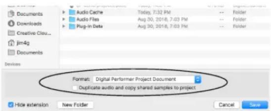
Figure 1-2: The 'Duplicate audio data and copy shared samples to project' option makes a copy of the entire project folder.
The Duplicate audio data and copy shared samples to project option is ideal for backing up Digital Performer projects, as well as transferring them to clients or collaborators, because it ensures that all associated audio files, analysis files, and shared samples are included.
AVOIDING DISASTER
Digital Performer project files often represent many hours of hard work. If something bad should happen to the file, and it's your only copy, you've lost all that hard work forever. So please follow these guidelines and make them habit:
Save early and save often
Make incremental backups with Save As
Backup early and backup often
For details about incremental backups, see “Using Save a Copy As for incremental backups” on page 26.
IMPORTING FILES IN OTHER FORMATS
Digital Performer can import a wide variety of industry standard interchange file formats. See “Importing project files in other formats” on page 33.
EXPORTING A PROJECT
Digital Performer can export a project to a variety of industry standard interchange formats. See "Exporting a project" on page 33.
MOVING A PROJECT BETWEEN MAC AND WINDOWS
Digital Performer runs on macOS and Windows. You can move Digital Performer projects between Mac and PC computers. Remember, however, that Audio Unit plug-ins and virtual instruments are Mac-only, so if they are used in a Digital Performer project on your Mac, they will not be available when you open the project in Digital Performer running under Windows.
All plug-ins and instruments included with Digital Performer will transfer across platforms just fine. The same is true for any VST plug-ins or instruments, as long as they are installed in both your Mac and PC systems. Check with the plug-in developer for information regarding any differences that may exist between their Mac and Windows VSTs.
Moving legacy Mac projects to Windows
If you have a legacy project created in an earlier (Mac-only) version of Digital Performer, check to see if it contains audio files in the Sound Designer II file format. If so, you'll need to open the project in the current version of DP running on a Mac to convert all SDII files to WAV files, as explained in chapter 77, "Audio File Conversion" (page 919).
After checking for SDII files and converting them, if any, save a copy of the project. Doing so creates an updated, cross-platform project file that is fully compatible with the Windows version of DP. In addition, the .dpdoc file extension is added to the end of the project file name, which is required by the Windows version of DP. The newly saved copy of the project can then be successfully opened by Digital Performer on a Windows computer.
INTERCHANGING WITH FINAL CUT PRO XML
Digital Performer can exchange XML files with Final Cut Pro 6 and 7. See “Interchanging with Final Cut Pro XML” on page 36.
EXPORTING TO NOTATION SOFTWARE THROUGH MUSICXML
Digital Performer can export a QuickScribe notation score as a MusicXML file for import into notation programs such as Finale™ and Sibelius™. See “Exporting a musicXML file” on page 521.
REVERTING TO A PREVIOUSLY SAVED PROJECT
If you've made unwanted changes to a project, you can undo the changes you've made by returning to the last saved version. This operation is identical to closing the project without saving and opening it again.
1 Choose Revert to Saved from the File menu.
A dialog box asks you to confirm this choice.
2 Click on OK to confirm the action, Cancel to withdraw it.
Reverting to the last saved version of the project means that all changes you've made since you opened or last saved the project will be lost.
Reverting to a previously saved version is useful when experimenting with a project. You can quickly discard all changes by using this command. Make sure that you save the file in the state you want it before beginning to experiment.
CREATING PROJECT TEMPLATES
The Save As Template command, found in the File menu, allows you to customize your copy of Digital Performer. You control what appears on the screen when you open a new project, by creating your own New project templates. You control the list of templates in the File menu> New sub-menu. A template is a “skeleton” project, a framework designed to save you time when building your project.
For example, let's say you typically work in projects with one sequence, the same number of tracks, measure time and SMPTE displays in the Large Counter, and a Sequence Start Time of measure -1. In addition, you arrange Digital Performer's windows to suit your screen size and style of working.
You can use the Save As Template command to give your 'New' projects all of these characteristics automatically. You can also create your own list of new file templates in the New sub-menu.
Creating a template
To create a template:
1 If you aren't already in a Digital Performer project, open one or choose New from the File menu.
2 Configure Digital Performer's windows, their contents, and any other features as you find most useful.
Digital Performer will remember your exact track setup, window layout, mix automation settings, and so on.
3 Choose Save As Template from the File menu.
A dialog appears.
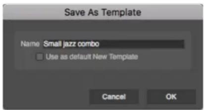
Figure 1-3: Naming a new template.
4 If you wish the template to be the default template when you create a new document, check the Use as default New Template box.
5 The newly created template now appears in the New command sub-menu (in the File menu).
Removing a template file from the sub-menu
To remove a template from the New command sub-menu, remove it from Digital Performer's document templates folder, which is located in your user directory preferences folder. Here is the path:
Platform Path
macOS \~/Library/Preferences/com.motu.DigitalPerformer/ Document Templates
Windows C:\ProgramData\MOTU\Digital Performer\Document Templates
You can quickly access this folder with the "Open Document Templates Folder" button under Preferences > Startup Options.
Creating a default New Template
When you check the Use as default New Template option, Digital Performer remembers the exact state of the project file and reproduces it when you request a new project. The File menu> New submenu command will produce an untitled, empty new project identical to the source project.
LOADING A SEQUENCE, SONG OR V-RACK
When a Digital Performer project is currently open, the Load command in the File menu lets you load sequences, songs and V-Racks from other projects directly into the open project without closing it. To load a sequence, song or V-Rack into an open project:
1 Choose Load from the File menu, click the file containing the sequence, song or V-Rack you wish to load, then click Open.
Alternatively, you can drag the Digital Performer project that contains the material you wish to load from the desktop and drop it into the Chunks window of the currently open project.
2 In either case, the Load window appears:

Figure 1-4: Loading a sequence, song or V-Rack from another project into the currently open file.
3 Make sure the Load Chunks option is checked.
If it is not, click its check box. The Chunks list displays all Chunks in the selected project.
4 Select the sequence, song or V-Rack you wish to load.
If you wish to load more than one, Shift-click or drag to select contiguous items and Command/Ctrl-click to select non-contiguous items.
5 Optional: If you wish to load any other items from the selected project, select the appropriate option.
6 Click OK to confirm your choice or Cancel to withdraw the Load command.
Clicking OK causes the selected Chunks to be placed in the Chunks window of the currently open Digital Performer project. You can change each item's position in the list by dragging its Type icon.
Loading a song automatically loads its component sequences (and songs). For example, you choose to load Song-1, which contains Seq-1, Seq-2, and Song-2. Song 2 contains Seq-3 and Seq-4. When you execute the Load command, all six Chunks (two songs and four sequences) will be loaded in and added to the Chunks list of the open project.
ADDING PROJECT NOTES
Choose Project menu> Project Notes to type in notes about your project. This is a simple text editor that allows you to store text within the project itself.
PRINTING PROJECT WINDOWS
You can print the contents of some Digital Performer windows. This includes list windows, such as the Event List, Tracks, Markers, Chunks, and Commands windows, and notation windows, such as the QuickScribe Editor.
Printing the contents of a list window
To print the contents of the Track List, an Event List, the Markers Window, the Chunks window, or the Commands window:
1 Bring the window you want to print to the front to make it the active window.
To do so, click its title bar or choose its name from the Window menu.
2 Choose Page Setup from the File menu, make any desired changes to the page settings, and click OK to confirm the settings.
The options that appear in this dialog box depend on the type of printer you are using. For example, if you are printing on a laser printer, you can choose an enlargement or reduction above or below 100%.
3 Choose Print from the File menu.
The standard print setup dialog box appears for your printer.
4 Set up the printer options as needed, such as the number of copies, and click OK.
The entire contents of the list is printed.
Printing notation
Printing notation in Digital Performer is easy. Digital Performer transcribes unquantized or quantized MIDI data in a readable fashion. You can format the music on screen exactly as it will print, including text, page margins, staff spacing, measure spacing, and more.
To print notation:
1 Choose Page Setup from the File menu, choose the desired page size, make any desired changes to the page settings, and click OK to confirm the settings.
The options that appear in this dialog box depend on the type of printer you are using. For example, if you are printing on a laser printer, you can choose an enlargement or reduction above or below 100%.
2 Select the MIDI track (or tracks) that you would like to print.
3 Open the QuickScribe Editor.
A window appears containing staves for the MIDI track or tracks you have selected. This window displays the music on a page exactly as it will print out. For information about editing music and formatting it in this window, see chapter chapter 43, “QuickScribe Editor” (page 479).
4 Use the QuickScribe Editor mini-menu and Page Setup commands to format the music on the page as desired.
Summarized below, these menu commands are discussed in detail in chapter chapter 43, "QuickScribe Editor" (page 479).
Formatting command Brief description
| Score Options(Mini-menu) | Provides control for title page, staff names, measure numbering and spacing, and staff spacing. |
| Page Margins(Mini-menu) | Lets you adjust top, bottom, left, and right page margins. |
5 Add text and musical symbols as desired with the text and symbol tools in the Tools palettes.
See "Working with text" on page 502 for more information.
6 Choose Print from the File menu.
The standard print setup dialog box appears for your printer.
7 Set up the printer options as needed, such as the number of copies desired, and click Print.
Digital Performer proceeds to print the document, providing you with a status window as it does.
CLOSING A PROJECT
To close a project, choose Close 'Project Name' from the File menu.
Closing a project without saving
If new audio files have been created in an unsaved project, and you don't save the project before closing, Digital Performer will alert you to the fact that there are unsaved audio files on disk:
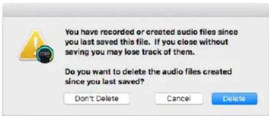
Figure 1-5: If you close an unsaved project, Digital Performer warns you about audio files that were created in the unsaved project and lets you either keep them or discard them.
The alert dialog shown above in Figure 1-5 lets you choose whether you want to delete them or not.
QUITTING/EXITING DIGITAL PERFORMER
Quitting or Exiting Digital Performer returns you to the computer desktop. On the Mac, choose Quit from the Digital Performer menu. On Windows, choose Exit from the File menu.
As when closing a project with unsaved changes, if you quit Digital Performer without saving your project a dialog box may appear asking you if you want to save changes made to the file. To save the changes, press Yes. If you don't want to save changes, press No. To withdraw the Quit command and return to your Digital Performer file, press Cancel.
SETTING DIGITAL PERFORMER'S STARTUP PREFERENCES
When Digital Performer first launches, you have four choices for what it can do:
■ Open a new project
■ Present you with the Open file dialog box, which lets you open either an existing project or a new project with the "New" button
■ Neither of the above, which lets you either choose Open or New from the File menu
■ Open the project you last had open
To set this preference, choose Preferences from the Digital Performer menu (macOS) or Edit menu (Windows), select the Startup Options pane, and choose the desired setting. This setting is stored in the Digital Performer Preferences file in the Preferences Folder inside your user library directory on your hard disk.
HELPFUL PROJECT AND DISK HINTS
File menu commands (except Save) cannot be used during playback. To use a command in the File menu, press the Stop button beforehand.
Save your file as often as possible. You should use the Save command after every significant change to your project. Consider using Autosave.
Always keep backup copies of your important projects. We cannot emphasize enough the importance of this. At the end of a working session, copy to a backup disk all of the files you recorded and edited. (The Save A Copy As command is good for this, together with the Duplicate Audio Data option.) If anything should happen to your original, you will have fully updated backup of the file.
Using the Save A Copy As command while working can be useful when you want to keep a record of earlier versions.
Be sure to backup your projects as often as is bearable, at least at the end of every working session and several times during the session if possible. The consequences of not making backups are severe: if your hard disk is damaged, some or all of the projects may be lost forever.
Using the macOS stationery feature (Mac only)
Digital Performer supports the macOS "Stationery pad" feature in the Get Info window for a project file as shown below:
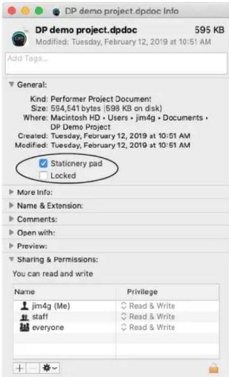
Figure 1-6: Stationery pad option in the Get Info window.
When this option is checked, the project file can be opened, but the Finder will prevent you from modifying the original file by forcing you to Save As when you attempt to save the project. This option is great for preserving projects that you do not want to modify and that you use regularly as a “template” from which to build other files. For more information about the Stationery pad option, consult your macOS help.
CHAPTER 2 Import and Export
OVERVIEW
This chapter provides a summary of the numerous importing and exporting features in Digital Performer.
Importing project files in other formats....33
Exporting a project....33
Exporting selections....35
Interchanging with Final Cut Pro XML....36
Importing and exporting audio....36
Bouncing audio files....40
IMPORTING PROJECT FILES IN OTHER FORMATS
Use the Open command in Digital Performer's File menu to open the following types of files:
■ Files created in earlier versions of Digital Performer and Performer
■ Files created in AudioDesk™
■ Standard MIDI files
■ OMF interchange files
■ AAF interchange files
After choosing one of these files in the Open dialog, a message will appear informing you that Digital Performer is converting file formats, if necessary. The file will open as a Digital Performer file; if you want to save it back into the Standard MIDI file format, see “Exporting a project” on page 33.
Standard MIDI files can also be imported and exported via drag and drop – see below.
Importing/exporting MIDI files via drag and drop
You can import and export standard MIDI files using Digital Performer's drag and drop capabilities. To import MIDI files, just drag them from the computer desktop into the Chunks window. To export a MIDI file, Command/Ctrl-drag a chunk in the Chunks window (by its handle) to the computer desktop. You can also do the same with a MIDI clipping, or a selection of MIDI data in the MIDI Editor or QuickScribe Editor.
Importing OMF/AAF files via drag and drop
You can import OMF and AAF interchange documents (with the .omf or .aaf file name extension) by dragging and dropping them into the Chunks window.
EXPORTING A PROJECT
Digital Performer can export projects in several other file formats:
■ Standard MIDI file (type 0 and type 1)
■ OMF interchange
■ AAF interchange
■ Digital Performer (Version 6.0, 5.12, 5.1, 4.6, 4.5, 4.1, 3.1)
■ AudioDesk (Version 2.0 and 1.0)
■ Final Cut Pro XML
To export a Digital Performer project to a different file format:
1 In the Chunks window, play-enable the sequence that you wish to save.
2 If you are saving a MIDI file, and you want the tempo and meter map of the sequence to be saved with the MIDI data, choose Conductor Track from the Tempo control menu in the Control Panel.
3 Choose Save A Copy As from the File menu.

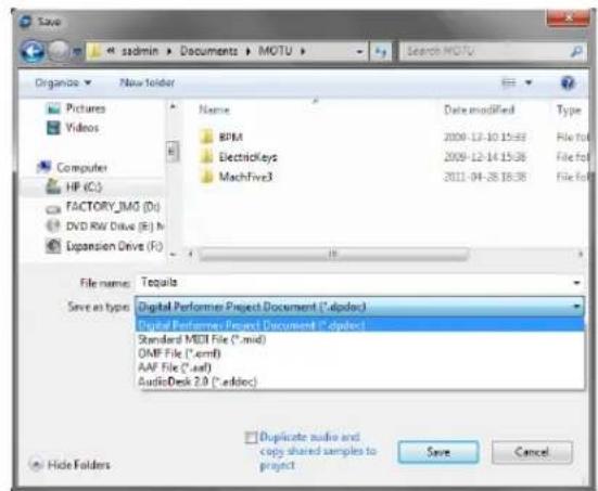
Figure 2-1: Using the Save A Copy As command to save a file in a different file format.
4 Choose the desired file format from the Format menu.
5 Click Save to activate the conversion.
6 If you are saving a standard MIDI file or OMF/AAF interchange document, you'll now see another window with several options that are specific to that file format.
Exporting songs
Only sequences can be exported in other file formats. If you wish to save a song, you can do so by converting it into a sequence beforehand. Refer to chapter 67, “Chunks Window” (page 793) to learn about converting a song into a sequence.
Exporting to a standard MIDI file
Use the procedure explained in “Exporting a project” on page 33. Music exported in the MIDI file format can be opened with any program that also reads and writes MIDI files — even programs that run on other types of computers. The following sections explain the MIDI File Options that appear on-screen during the export process.

My DP Project.mid
Figure 2-2: The file icon for a standard MIDI file created by Digital Performer.
MIDI File Format options
When you export to a standard MIDI file, the following dialog box appears:

Figure 2-3: Digital Performer's options for exporting to a standard MIDI file.
File format
Digital Performer can export the following types of standard MIDI files:
| MIDI file format | Description |
| Format 1 Separate tracks with tempo and meter information as the first track. | |
| Format 0One multi-channel track | One multi-channel track with tempo/ meter information at the beginning. |
| Format 0Tempo/meter map only | Conductor track only with tempo data and a meter map |
Save track names as plain text
When selected, the Save track names as plain text option causes only plain text events, such as track names, to be saved. No special text events, such as track comments, are saved. This option is necessary when transferring files to programs that do not support special text events. If you discover inconsistencies when transferring text in MIDI files, try using this option.
Expand loops and capture effects
Standard MIDI files cannot contain loops or real-time MIDI effects processing. The Expand loops and capture effects option addresses this problem by converting each loop into a region of repeated data in the same way as Digital Performer's Repeat command. The End file at time option allows you to specify the end time of the sequence in the box provided. For convenience, the box appears with the sequence's current end time. Similarly, all real-time effects processing is written permanently to the data as it is exported.
Digital Performer can also import MIDI files. For more information, see “Importing project files in other formats” on page 33.
Exporting to earlier versions of Digital Performer
Digital Performer is constantly being updated and developed. Due to these changes, projects saved in the current version cannot be opened in earlier versions of Digital Performer. If for some reason you need to work with a project in an earlier version, Digital Performer lets you export projects in any format as far back as Digital Performer Version 3.1. Just use the procedure described in "Exporting a project" on page 33.
When saving to older versions of Digital Performer, the audio files in your project may need to be converted if they are not compatible with that version of Digital Performer you are saving to. If this is the case, a dialog will prompt you that the audio must be copied and converted to a supported format.
The following audio file formats are not supported in Digital Performer 5.13 or earlier:
AIFF
■ Broadcast WAVE
- interleaved
■ 32-bit floating point
Additionally, when saving as Digital Performer 5.11 or earlier, mixed sample formats are not supported (all files must be the same bit depth).
Exporting to AudioDesk
Digital Performer can export projects to AudioDesk Version 1.0 and 2.0, via the procedure described in “Exporting a project” on page 33.
Exporting to OMF or AAF
Digital Performer can export projects to OMF and AAF files. See chapter 6, “Project File Interchange” (page 61).
EXPORTING SELECTIONS
Exporting a selection as a MIDI file
To export the currently selected MIDI data as a MIDI file, choose File menu > Export > Selection As MIDI File.
Exporting a selection as a clipping file
To export the currently selected audio and/or MIDI data as a clipping, choose File menu > Export > Selection As Clipping File. See chapter 55, "Clippings" (page 705) for more information about clippings.
INTERCHANGING WITH FINAL CUT PRO XML
Digital Performer can interchange projects using the Final Cut Pro XML format, using the Import Final Cut Pro 7 XML and Export Final Cut Pro XML File menu commands. See “Final Cut Pro XML interchange” on page 67.
IMPORTING AND EXPORTING AUDIO
The Soundbites window (chapter 3, “Soundbites Window” (page 41)) provides many features for exporting and importing digital audio into and out of Digital Performer. Many audio file formats are supported.
Importing audio with the Import Audio command
The Import Audio command lets you to browse audio files and soundbites before importing.
To import using the Import Audio command, choose Import Audio from the File menu (or the Soundbites window mini-menu). You'll see the standard file window (as shown below in Figure 2-4). In this window, you can import individual regions from an audio file (unlike drag & drop into the Soundbite list, which imports all regions), and you can audition them before importing. (See “Specifying audio output for auditioning” on page 338.)
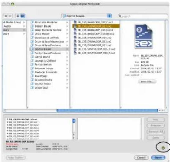

Figure 2-4: Importing audio. On macOS, click the audition button (circled) to turn on auditioning. This allows you to hear individual audio regions when you click them. Click the Add button to add them to the list of regions you would like to import. As you can see, this window lets you import individual audio regions.
Video sound tracks, MP3 files and many other types of audio files can be auditioned in the Import Audio dialog.
Digital Performer can natively use interleaved or deinterleaved 16-bit, 24-bit, or 32-bit floating point audio files in AIFF and WAVE formats.
Other types of audio files are converted into the project audio file format for use in Digital Performer. For a list of audio file types that can be imported, see “Audio file formats that can be
imported" on page 37, and for details on the conversion settings, see "Automatic Conversions" on page 920.
Importing and exporting audio by drag & drop
Digital Performer supports standard drag and drop techniques for importing audio files from the computer desktop into any window in Digital Performer that holds audio, such as the Soundbites window. This is true for all of the supported file formats listed in “Audio file formats that can be imported” on page 37. If the imported file does not match one of Digital Performer’s supported native formats, Digital Performer can automatically convert the file for you.
Soundbites can be exported in a similar fashion by grabbing their move handle in the Soundbites window and dragging them to the computer desktop (or any window on the computer desktop).
Importing an entire audio file
The easiest way to import an entire audio file is to drag and drop it into a track in Digital Performer's Tracks window or Sequencer Editor. Make sure the track type (mono or stereo) matches the audio file. You can also import an entire audio file using the Import Audio File menu command as described in the previous few sections.
Loading soundbites from other Digital Performer files
You may encounter a situation in which you have created soundbites in another Digital Performer file and you would like to work with them in the current Digital Performer file. To load soundbites from another Digital Performer file, use the Load command in the File menu and check the Soundbites option. For details, see “Loading a sequence, song or V-Rack” on page 29.
Converting soundbites that cannot be played
When you import soundbites into Digital Performer, it may be the case that they cannot be played properly. For example, the imported audio's sample rate might not match the playback sample rate currently chosen in the Configure Hardware dialog box. In this case, Digital Performer can automatically convert the audio to the project's sample rate, sample format and even tempo. For complete details, see “Automatic Conversions” on page 920.
If an audio file has a sample rate that does not match the current sample rate setting in the Configure Audio System > Configure Hardware Driver command in the Setup menu, it appears with an "X" on its move handle in the Soundbites window, as shown in Figure 3-12 on page 49. You can play the audio file either by changing the sample rate setting in the Configure Hardware dialog to match the audio file, or by changing the sample rate of the audio file itself with the Convert Audio File command in the Soundbites window mini-menu. For more information, see chapter 77, "Audio File Conversion" (page 919).
Audio file formats that can be imported
Digital Performer is able to import the following audio file formats:
AIFF
■ WAV
■ Broadcast WAV (non-MPEG)
■ Sound Designer II
■ mp3
- Acid
■ REX (and RCY)
■ Apple Loops (AIFF or CAF)
■ Core Audio Format (CAF)
■ QuickTime movies
■ AVI movies
■ Audio CD files
■ MuLaw files
You can import any of the file formats above by dragging the file into Digital Performer and dropping it into the Soundbites window or — in most cases — any window that holds audio.
If you drag and drop an audio file into Digital Performer's Soundbites window, all of the regions in the audio file are imported.
Importing REX files
Recycle 1.0 and 2.0 REX files can be imported into Digital Performer, either by dragging and dropping them from the computer desktop into a mono or stereo audio track, or by using the Import Audio command (File menu). Recycle 1.0 RCY files can also be imported.
Importing a REX file into a track
When you drag and drop a REX file into a track, be sure that the track format (mono or stereo) matches the REX loop. As shown in Figure 2-5, the individual audio slices in the REX loop are placed in the track at the appropriate measure, beat and tick location to preserve the feel of the loop at the current tempo of the sequence. After importing, each slice of the REX loop is treated as in individual soundbite, both in the track and in the Soundbites window.
If you change the tempo, the REX slices will "breath" with the tempo, staying precisely in time with the conductor track. When they are first imported, REX slice soundbites are given the Don't time scale attribute in the Soundbites window, so each individual slice won't be automatically time-stretched when the tempo is changed. However, you can easily change this attribute to Time Scale in the Soundbites window, as explained below.

Importing REX files into the Soundbites window You can import REX files using the Import Audio command in the Soundbites window mini-menu (or the File menu). This opens the audio import window, in which the REX file can be auditioned before importing. Just enable auditioning by clicking the speaker button and the click on the REX file in the file list. After importing, all of the REX file's individual slices are handled as individual soundbites, with no further grouping or association. Therefore, it is better to drag and drop a REX file into a track, where you can then loop, repeat or cut/paste it as a whole loop.
Viewing REX loop slices and changing their time-stretch attribute
You can easily view all of the soundbite slices that belong to a REX file with the Soundbite window's sorting features. Just view by file name, and the REX file will appear with a disclosure triangle next to its name that lists all slices below it. If you wish to change the time scale attribute of the slices, select them and open the Sound File Information window, and choose either Time Scale or Don't Time Scale for the Time Compress/Expand soundbite attribute. You can do so for multiple selected soundbites (REX slices) at one time. If you don't time scale the slices, you might (but are unlikely to) hear gaps between the slices when using the loop at a tempo that is considerably less than its original tempo. Most of the time, however, you will get better results with the Don't Time Scale setting, which preserves the audio slices in their original form (tempo). For more details, see "Sound File Information" on page 365.
Acid file and Apple Loop import
Digital Performer can import Acid WAV and Apple Loop AIFF files. To do so, drag and drop the Acid or Apple Loop file into the Soundbites window or into an audio track of the same format (mono or stereo). Or import them as usual using the Import Audio command in the Soundbites window mini-menu (or the File menu). If the file has a tempo, the tempo will be imported with the audio so that it will automatically conform to the sequence tempo when placed in a track, as long as automatic tempo conversion (as explained in “Automatic Conversions” on page 89) is enabled.
Audio file exporting
The Export Selected Soundbites command in the Soundbites window mini-menu can export any soundbite in the file formats shown in Figure 2-6 for Mac and Windows.

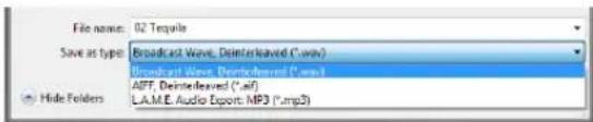
Figure 2-6: The audio export file formats.
For the macOS Core Audio Export formats, stereo soundbites are exported in the interleaved stereo version of these formats.
For further information about exporting to the MP3 file format, see “Bouncing to MP3” on page 960, as MP3 export works the same way for bouncing as it does for exporting.
Saving an audio export preset
To create and save an audio export preset, check the Save Settings as Audio Export Format option in the audio export dialog (Figure 2-6). If there are any additional settings required, they will appear in subsequent dialogs. Then, you'll be asked to
name your export preset. After a preset has been saved, it appears in the audio export file format menu (shown in Figure 2-6) for your convenience, as well as the Bounce to Disk format menu (Figure 84-8 on page 959). To use an export preset, simply choose it from the menu when bouncing or exporting. These presets are saved as a preference, so they are not project-specific. They are global to all projects. See also “Editing audio export presets” on page 959.
BOUNCING AUDIO FILES
Digital Performer's Bounce to Disk feature is a powerful and convenient way to export material, from small phrases to entire mixes. See “Bouncing to Disk” on page 953.
CHAPTER 3 Soundbites Window
OVERVIEW
This chapter assumes that you are familiar with terms like audio file, region, soundbite, playlist and audio track. If not, review chapter 8, “Hard Disk Recording Concepts” (page 55) in the DP4 Getting Started Guide.
As you work with Digital Performer, you'll create many soundbites. The soundbites window helps you manage them. Think of the Soundbites window as your “catalog” of audio data. It lists all of the portions of audio that you are dealing with in the project. It helps you keep the ones you want and throw away the ones you don't. A complete built-in waveform editor is included for Pencil tool removal of click and pops and many other waveform editing tasks.
Quick Reference....41
Soundbites window mini-menu....42
Opening the Soundbites window....43
The Soundbite list ....43
Soundbite Basics ....47
Mono, stereo and multi-channel audio ....47
Importing and exporting audio....47
Soundbite Management 47
Dragging and dropping soundbites ....51
Working with multiple sample formats ....52
Converting sample rate/format ....52
Automatic conversions 52
Reload Soundbite ....53
Replace Soundbite ....53
Edit in Waveform Editor....53
Use external waveform editor ....53
Viewing more Sound File Information ....53
QUICK REFERENCE

The Soundbites window serves as a catalog and "command center" for all of the audio files in a project.
Soundbite list: The soundbite list shows detailed settings for each soundbite.
Columns: Each column displays one piece of information about a soundbite: name, file name, duration, sample rate, sample format, timestamp, and so on. You can choose which columns to show and how they are ordered.
View By menu: This controls how the soundbites how are sorted: by soundbite name, audio file name, duration, sample rate, and so on.
Search box: Searches soundbite names and audio file names for the entered text. As you type a search term, the window will update in real-time to display the relevant results.
SOUNDBITES WINDOW MINI-MENU

Figure 3-1: Soundbites window mini-menu.
New Audio File: Creates an empty mono, stereo or multichannel audio file on your hard drive. You can then paste material into it or otherwise do what you want with it. For further information, see “Creating a new, empty audio file” on page 542.
New Audio File from Selection: Creates a new, separate audio file on your hard drive based on the currently selected soundbite. In other words, the new audio file will contain a copy of the currently selected audio.
Import Audio: Opens a dialog box that allows you to audition and import audio files and/or individual soundbites (regions). This is the same as the Import Audio command in the File menu.
Export Selected Soundbites: Lets you save the currently selected stereo soundbites in a variety of file formats, including AIFF, WAVE, Sound Designer II, and MP3.
Edit Audio Export Formats: Lets you delete and rename saved audio export formats. See “Saving an audio export preset” on page 39.
Columns Setup: Lets you show and hide the columns in the Soundbite list.
Create New Folder: Adds a new folder to the soundbite list. This command is only available when Folders is chosen in the View by menu at the top of the Soundbites window.
Select unused soundbites: Highlights all soundbites in the list that are not currently being used in any tracks in any sequence in the file. The highlighted soundbites can be removed from the list or deleted entirely from their parent audio file. (Note that the audio data itself is not removed by deleting. See Compact below.)
Compact: Caution! Unlike Delete, this command actually removes audio data from the hard disk. Compact removes all portions of the parent audio file of the currently selected soundbites which are not defined as a region in the audio file region list. This command can be used to remove unused audio data in one or more audio files to free up space on the hard disk.
Convert Audio File: Opens a dialog box that lets you change the sample rate, sample format, file format, and/or interleaved format of the currently selected soundbites in the list. Several levels of quality are provided. For complete information, see chapter 77, “Audio File Conversion” (page 919).
Automatic Conversions Settings: Opens the Automatic Conversions preferences where you configure how Digital Performer automatically converts audio data, wherever necessary, to make it conform to the current project's sample rate, file format, interleave format, and tempo.
Remove From List: Deletes the soundbite from the Soundbites window list without deleting its corresponding region in the audio file region list.
Delete: Removes the selected soundbites from the list, removing Digital Performer's reference to the data from the Soundbites window. If the soundbite
is the last one in the parent audio file to be deleted,
Digital Performer asks if you would like to delete the parent audio file entirely.
OPENING THE SOUNDBITES WINDOW
To open the Soundbites window, choose Project menu>Soundbites, or press its keyboard shortcut, Shift-B. To open it in a sidebar, choose it from any sidebar cell menu (Figure 10-5 on page 115).
THE SOUNDBITE LIST
The Soundbite list provides a complete list of all soundbites in the Digital Performer project, along with detailed information about each soundbite.
Showing/hiding columns in the soundbite list
at the beginning of this chapter (page 41) shows the default information shown in the soundbite list. The Columns Setup mini-menu item lets you show and hide columns as desired. (As a shortcut, double-click or Option/Alt-click the label at the top of one of the columns to open these preferences.) Figure 3-2 below shows all of the columns.

Figure 3-3: Double-click or Option/Alt-click any column title in the Soundbites window to open the Columns Setup preferences.
Rearranging soundbite list columns
To rearrange the order of the columns (as in the Tracks window), drag the label at the top of a column to the left or right. Digital Performer saves your customized column arrangement in the Digital Performer preferences file, so it is remembered in all of your Digital Performer files.
Soundbite list quick reference
Here is a brief explanation of each column in the soundbite list.
Move Handle: Drag up or down to reposition the soundbite in the list. Also use it to drag and drop the soundbite into other windows or the computer desktop. When dropping it into an audio track in the Sequence Editor, hold down the Command/Ctrl key while dragging to make it “snap” to the end of the previous soundbite in the track. A question mark icon on the move handle means that Digital Performer does not currently know the location of the audio file containing the soundbite. The soundbite can’t be played and its waveform can’t be displayed. An ‘X’ icon on the move handle means that Digital Performer cannot currently play the soundbite for some reason. For example, it may not match the current sample rate setting of your audio hardware. For details, see “Lost soundbites” and “Finding lost soundbites” on page 49.
Name: Displays the name of the soundbite (region). Click the name to select it. To hear it play back, turn on Audible Mode in the Control Panel
| Soundbites | ||||||||||||||
| View by: Name | ||||||||||||||
| NO. | NAME | ORDER NAME | SIZE NAME | PAGE | DESCRIPTION | TYPE | # FLOOR | SUPPORT CODE | LOCATION NAME | SERVICE | OFF | RISK | FETA TYPE | DIMENSIONS |
| -1 | Cube | Mini-90 | 092.16 | = 110.00 | 3463 | 44300 | Convent Format | 2008/04/10 | 15.35 | 16 BR | # ++ | Storage: WAVE | ||
| -2 | Cube Beat | Mini-80 | 091.09 | = 110.00 | 2001 | 44300 | Convent Format | 2008/04/10 | 15.35 | 16 BR | # ++ | Storage: WAVE | ||
| -3 | Cube Fill | Cube Fill | 091.09 | = 110.00 | 2003 | 44300 | Editing | 1999/01/27 | 08.42 | 16 BR | # ++ | Storage: Sound Designer II: Mono | ||
| -4 | P A1 Seat | P #1 Seat-02 | 091.09 | = 110.00 | 2001 | 44300 | Convent Format | 2006/04/10 | 15.34 | 16 BR | # ++ | Storage: AFF | ||
| -5 | P #2 Seat | P #2 Seat-03 | 091.16 | = 110.00 | 2063 | 44300 | Convent Format | 2008/04/10 | 15.34 | 16 BR | # ++ | Storage: AFF | ||
| -6 | P A3 Seat | P #3 Seat | 091.44 | = 110.00 | 2135 | 44300 | Editing | 1999/01/27 | 08.45 | 16 BR | # ++ | Storage: Sound Designer II: Mono | ||
| -7 | P A4 Seat | P #4 Seat | 091.44 | = 110.00 | 2319 | 44300 | Editing | 1999/01/27 | 08.45 | 16 BR | # ++ | Storage: Sound Designer II: Mono | ||
| -8 | Mini-90 | Mini-90 | 091.87 | = 110.00 | 1464 | 44300 | Convent Format | 2008/04/10 | 15.35 | 16 BR | # ++ | Storage: WAVE | ||
| -9a) | Phoctor loop 0.00.00 9.09.09.08 9.09.09.08 9.09.09.08 9.09.09.08 9.09.09.08 9.09.09.08 9.09.09.08 9.09.09.08 9.09.09.08 9.09.09.08 -9a) Phoctor loop-03 -9a) Phoctor loop-02,2 -9a) Phoctor loop-02,1 -9a) Speedin@2b 8: 8: 8: 8: 8: 8: 8: 8: 8: 8: 8: 8: 8: 8: 8: 8: 8: 8: 8: 8: 8: 8: 8: 8: 8: 8: 8: 8: 8: 8: 8: 8: 8: 8: -9a) Wha Guitar -9a) Wha Guitar,2 -9a) Wha Guitar,3 SPRING HP276 SPRING HP276 SPRING HP276 SPRING HP276 SPRING HP276 SPRING HP276 SPRING HP276 SPRING HP276 SPRING HP276 SPRING HP276 SPRING HP276 SPRING HP276 SPRING HP276 SPRING HP276 SPRING HP276 Spindle@2b Spindle@2b Spindle@2b Spindle@2b Spindle@2b Spindle@2b Spindle@2b Spindle@2b Spindle@2b Spindle@2b Spindle@2b Spindle@2b Spindle@2b Spindle@2b Spindle@2b Spindle@2b Spindle@2b Spindle @2b Spindle @2b Spindle @2b Spindle @2b Spindle @2b Spindle @2b Spindle @2b Spindle @2b Spindle @2b Spindle @2b Spindle @2b Spindle @2b Spindle @2b Spindle @2b Spindle @2b Spindle @2b Spindle @2b SPEED HP276 SPEED HP276 SPEED HP276 SPEED HP276 SPEED HP276 SPEED HP276 SPEED HP276 SPEED HP276 SPEED HP276 SPEED HP276 SPEED HP276 SPEED HP276 SPEED HP276 SPEED HP276 SPEED HP276 Spindle @2b Spindle @2b Spindle @2b Spindle @2b Spindle @2b Spindle @2b Spindle @2b Spindle @2b Spindle @2b Spindle @2b Spindle @2b Spindle @2b Spindle @2b Spindle @2b Spindle @2b Spindle @2b Spindle@2b Spindle@2b Spindle@2b Spindle@2b Spindle@2b Spindle@2b Spindle@2b Spindle@2b Spindle@2b Spindle@2b Spindle@2b Spindle@2b Spindle@2b Spindle@2b Spindle@2b Spindle@2b SPEED HP276 SPEED HP276 SPEED HP276 SPEED HP276 SPEED HP276 SPEED HP276 SPEED HP276 SPEED HP276 | |||||||||||||
Figure 3-2: The soundbite list with all detail columns shown.
and then click it. Option/Alt-click the name to rename the soundbite. Double-click the name to edit the soundbite in Digital Performer's built in Waveform Editor or in a third-party audio editor such as Bias Peak ™ (see page 53).
Original time: The time at which the soundbite was originally recorded (or created), regardless of where it currently resides. If a soundbite does not have an original timestamp (perhaps it was created in an earlier version of Digital Performer that didn't support timestamping), then no time is shown. For details, see “Show times” on page 398.
User time: Displays the soundbite's user timestamp, if it has one. A user timestamp can be applied to a soundbite at any time with the Timestamps command in the Audio menu. If a soundbite does not have a user timestamp, then no time is shown. For details, see "Show times" on page 398.
Duration (real time): Indicates the length of the soundbite in hours, minutes, seconds, and hundredths of a second.
Ticks (duration in ticks): Displays the length of the soundbite in quarter notes and ticks. If the soundbite doesn't have a tempo map, this column will be empty.
Tempo: In order to make time-scaling musically useful, Digital Performer allows Soundbites to have tempo maps. This makes it very easy for you to manipulate audio along with MIDI without worrying about the tempo, and change the tempo however and whenever you want. A soundbite does not have to have a tempo, but if it does, it is displayed here. If the tempo of the soundbite varies, the average tempo is shown (labeled “avg.”) If the soundbite doesn’t have a tempo map, this column will be empty. For complete information, see chapter 52, “Tempos and Audio” (page 673). Sample Rate: Indicates the rate in samples per second at which the audio data making up the soundbite was sampled.
Format: Displays the bit depth (e.g. 16-bit, 24-bit, or 32-bit floating point) of the audio data in the soundbite.
Interleaved Format: Displays the interleaved format (mono, deinterleaved, or interleaved) of the audio file the soundbite is from.
Creation Time: Displays the date and time that the soundbite was created.
Source: Explains briefly how the soundbite was created.
DSP: The DSP column shows the soundbite's preference settings for transposing and time scaling. These settings determine what happens (or does not happen) when you attempt to transpose to time-scale the soundbite. Each soundbite can have its own unique settings. For complete information about these preferences, how to set them, and what the results will be, see "Dragging and dropping soundbites" on page 51.
File: This is the name of the audio file that contains the soundbite. Double-click to replace or relocate the soundbite. Option/Alt-click to change the name of the audio file.
Disk: Shows the name of the disk on which the audio file resides.
Shortcuts for finding soundbites in the Soundbite list
The shortcut for selecting a soundbite in a track (in the Sequence Editor or other edit window) and then viewing that soundbite in the Soundbites window is Command-Option-Control-L (Mac) or Ctrl-Alt-Win-L (Windows).
Keyboard shortcuts are also available for viewing the selected soundbite in the Sound File Information window (Command-Option-Control-A on the Mac and Ctrl-Alt-Win-A on Windows) or in the Waveform Editor (Command-Option-Control-W on the Mac and Ctrl-Alt-Win-L on Windows).
View By menu
The View By menu at the top of the Soundbites window is a powerful sorting feature that allows you to view soundbites hierarchically by the characteristics shown below in Figure 3-4:

Figure 3-4: Hierarchical sorting in the Soundbite list.
When you choose an item from the View By menu, the Soundbites window sorts all soundbites alphabetically and/or numerically based on what you choose, displaying soundbites hierarchically beneath the attribute that you choose, with disclosure triangles so that you can show/hide all of the soundbites for a certain attribute. For example, if you sort by file name, audio files will be listed alphabetically with a disclosure triangle that shows the soundbites indented to the right beneath it, as demonstrated below in Figure 3-5: Here are a few other examples: you could sort by Time Created to find a soundbite you recorded during a particular recording session. Or you could sort by Channel Format to view all stereo soundbites currently being used.

Figure 3-5: Sorting by file name.
Organizing soundbites into folders
The Soundbites window allows you to create your own folders and then view soundbites By Folder. To create a folder, first view By Folder and then choose Create New Folder from the Soundbites window mini-menu. A new Folder appears, either at the bottom of the list or just below the currently selected item in the list. You can then drag soundbites into it using their move handles.
When creating a new folder, you may need to scroll to the bottom of the list to see the new folder.
Command-double-click a folder (or any other 'view by' container) to select all soundbites within it.
Soundbite source
The Soundbites window displays the source of each soundbite (as shown in Figure 3-6), to provide you with information about where it came from. For example, the source might say
"Transpose from Guitar.1" or "Bounce". This setting can often help you trace the relationships between soundbites.
Viewing soundbite sources hierarchically with 'By Folder' view
The By Folder view has one additional feature over other views: it displays the sources of soundbites and newly generated audio files hierarchically, so that you can trace their origins. For example, if you use the Edge Edit Copy feature to make a new soundbite from an existing soundbite, the new soundbite will be listed below the original with an indentation to the right. If you make yet a third soundbite from the second, it will be listed below the second and further indented to the right. This is demonstrated in Figure 3-7:
| MVE | NAME | FILE | DURATION |
| JF #1 Scat | JF #1 Scat-02 | 0:01.09 | |
| JF #1 Scat.2 | JF #1 Scat-02 | 0:01.09 | |
| JF #1 Scat.3 | JF #1 Scat-02 | 0:00.55 | |
| JF #1 Scat.5 | JF #1 Scat-02 | 0:00.26 | |
| JF #1 Scat.6 | JF #1 Scat-02 | 0:00.28 | |
| JF #1 Scat.4 | JF #1 Scat-02 | 0:00.53 | |
| JF #2 Scat | JF #2 Scat-02 | 0:01.16 | |
| JF #3 Scat | JF #3 Scat | 0:01.44 | |
| JF #4 Scat | JF #4 Scat | 0:01.44 |
Figure 3-7: The 'By Folders' view shows the origins of soundbites by displaying them below their source soundbite or audio file. In this example, 'JF #1 Scat.2' was created by duplicating 'JF #1 Scat.' And 'JF #1 Scat.3' was created by edge editing 'JF #1 Scat.2'.
There is no limit to the number of possible levels in the hierarchical display shown above in Figure 3-7. This sort of hierarchical grouping only occurs for audio files generated from existing files by operations (such as spectral effects, time-stretching, file-based plug-in processing from the plug-ins menu in the Audio menu, etc.) or from soundbite editing operations (such as Edge Edit Copy) where there is a clearly defined source soundbite.
You can separate hierarchically related items by dragging them elsewhere in the list, but the visual representation of their relation to one another cannot be later restored after you've done so.
Dragging soundbites into folders
In 'By Folder' view, there are two ways to put a soundbite into a folder:
- by dragging the soundbite's move handle into the name column to manually determine its position in the list, or
- by dragging the soundbite's move handle onto the folder name in the name column. In this case, the soundbite will be put at the top of the list inside the folder.
If you drag the soundbite's move handle onto the folder icon, the soundbite will not be placed in the folder. Instead, it will be placed below the folder in the list.
Searching the Soundbites list
A search field is provided to search soundbite names and audio file names.
| MVE | NAME | FILE | DURATION | SOURCE |
| Gruve | Mini-fill | 0:02.16 | Convert Format | |
| Gruve Beat | Mini-fill | 0:01.09 | Convert Format | |
| Gruve Fill | Gruve Fill | 0:01.09 | Editing | |
| JF #1 Scat | JF #1 Scat-02 | 0:01.09 | Convert Format | |
| JF #1 Scat.2 | JF #1 Scat-02 | 0:01.09 | Duplicate Soundbite | |
| JF #1 Scat.3 | JF #1 Scat-02 | 0:00.55 | Editing | |
| JF #1 Scat.4 | JF #1 Scat-02 | 0:00.53 | Editing | |
| JF #1 Scat.5 | JF #1 Scat-02 | 0:00.26 | Editing | |
| JF #1 Scat.6 | JF #1 Scat-02 | 0:00.28 | Editing | |
| JF #2 Scat | JF #2 Scat-02 | 0:01.16 | Convert Format | |
| JF #3 Scat | JF #3 Scat | 0:01.44 | Editing | |
| JF #4 Scat | JF #4 Scat | 0:01.44 | Editing | |
| Mini-fill | Mini-fill | 0:01.07 | Convert Format | |
| Phasor loop | Phasor loop-02.% | 0:04.00 | Convert Format | |
| Phasor loop-02 | Phasor loop-02.% | 0:01.46 | Create Soundbite From Editor Selection |
Figure 3-6: The Soundbites window displays where a soundbite came from in the Source column. In this example, the soundbite list is being sorted by source, as well.

Figure 3-8: Searching the Soundbites list
As you type a search term, the window will update in real-time to display the relevant results.
To clear the search results and return to the regular view, click the "x" button at the right side of the search field, or press the Escape key.
SOUNDBITE BASICS
A new soundbite is created in Digital Performer every time you record audio. For example, when you record-enable an audio track, hit the record button, play in some audio, and press stop, you have just created a soundbite in the track. In addition, the soundbite gets added to the list in the Soundbites window. New soundbites are also generated when you apply file-based DSP operations to existing soundbites, or perform a bounce to disk operation. Any time you create new audio, a soundbite is added to the soundbite list.
Generating soundbites while editing
Soundbites can also be created in Digital Performer with soundbite editing commands like Trim, Split, and Strip Silence. For example, when you select a portion of the existing soundbite and choose Trim, the unselected portions get stripped away, and the highlighted portion that you are left with is a new soundbite. As always, the new soundbite gets added to the list in the Soundbites window.
MONO, STEREO AND MULTI-CHANNEL AUDIO
Soundbites may be mono, stereo or multi-channel (surround). Digital Performer supports both interleaved and deinterleaved audio files as native formats.
When using interleaved audio files, a stereo or multi-channel soundbite stores all of its channels in one file.
When using deinterleaved, a stereo soundbite comes from a stereo pair of files that have the same name (except that one contains '.L' and the other '.R', as in "Guitar-1.L.wav" and "Guitar-1.R.wav"), the same length, the same sample rate, and the same sample format. The same is required for multi-channel files: they must have the same length, sample rate, sample format, and name (with appropriate filenames containing .L, .R, .C, .Ls, .Rs, .LFE, etc.).
When using the deinterleaved format, you can't really tell the difference from within the program. You can think of a stereo or multi-channel soundbite as a single soundbite that just happens to have individual channel components. But the channels are tightly linked; there is no way to accidentally shift one relative to the other. Even Digital Performer's pitch-shifting, time-scaling, and tempo-adjusting features preserve the phase relation between the left and right channels of stereo soundbites.
IMPORTING AND EXPORTING AUDIO
Digital Performer provides a variety of methods for importing and export audio to and from the Soundbites window. See chapter 2, “Import and Export” (page 33).
SOUNDBITE MANAGEMENT
As you work with Digital Performer, you'll create many soundbites. The Soundbites window helps you manage them. Think of the Soundbites window as your "catalog" of audio data. It lists all
of the portions of audio that you are dealing with in the file. It helps you save the ones you want to keep and throw away the ones you don't.
Sorting the soundbites list
The View by menu at the top of the Soundbites window lets you sort soundbites by any criterion shown in the list. For details, see "View By menu" on page 45.
Auditioning soundbites with Audible Mode
There are two ways to audition (play back) a soundbite in the Soundbites window:
1 Click the Audible mode button in the Control Panel so that it is highlighted.
2 Click the name of the soundbite you wish to hear.
3 To stop playback, wait for the soundbite to finish playing, or click the mouse.
Alternatively, you can do the following, regardless of whether the Audible Mode button is highlighted or not:
1 Highlight the name of the soundbite you wish to hear.
2 Option/Alt-click the Audible Mode button.
3 To stop playback, wait for the soundbite to finish playing, or click the mouse.
Specifying the audio output for auditioning
See "Specifying audio output for auditioning" on page 338.
Adjusting the volume for auditioning
To adjust the volume for previewing, use the Audition volume preference. See “Audition volume” on page 95.
Renaming a soundbite
To rename a soundbite in the soundbites window, Option/Alt-click its name.

Figure 3-9: Renaming a soundbite.
When you change the name of a soundbite, Digital Performer updates the name of the corresponding region in the audio file. For example, if you use the Split command to create a new soundbite, it appears in the Soundbites window with a name like Soundbite.3. Digital Performer adds a new region to the audio file region list called Soundbite.3 as well. At this point, if you viewed the audio file's region list with third-party waveform editing software, you would see Soundbite.3 in the audio file's region list. If you change the name of Soundbite.3 to Low whistle in Digital Performer's Soundbites window, Digital Performer updates the name of Soundbite.3 to Low whistle in the audio file region list as well.
Lost soundbites
At times, Digital Performer may lose track of the location of an audio file. For example, the audio file may have been dragged to the trash since the Digital Performer file was last saved. Or the hard disk on which the audio file is located may be off
line at the moment. In this case, Digital Performer displays the move handle of the soundbite with a question mark as shown below:
| JF #3 Scat | JF #3 Scat | |
| JF #4 Scat | JF #4 Scat | |
| Mini-fill | Mini-fill | |
| Phasor loop | Phasor loop-02.1M | |
| Phasor loop-02 | Phasor loop-02.1M | |
| Phasor loop-02.2 | Phasor loop-02.1M | |
| Phasor loop-02.3 | Phasor loop-02-02-02 | |
| SpeedHip20 | SPEEDHIP20.1M |
Figure 3-11: Digital Performer displays this icon when it does not currently know the location of the audio file containing the soundbite.
Finding lost soundbites
If Digital Performer does not know the location of a soundbite as shown in Figure 3-11, you can remind Digital Performer where it is using the Replace Soundbite command in the Audio menu. Click the name of the soundbite to highlight it and choose Replace Soundbite from the Audio menu. For more information, see “Replace Soundbite” on page 655.
Soundbites that cannot be played
If a soundbite cannot be played back for some reason (perhaps its sample rate doesn't match the current sample of the project), Digital Performer displays an "X" icon as shown below:
| ✓ | JF #3 Scat | JF #3 Scat |
| JF #4 Scat | JF #4 Scat | |
| ✘ | Mini-fill | Mini-fill-48000 |
| Phasor loop | Phasor loop-02. 1/k | |
| Phasor loop-02 | Phasor loop-02. 1/k | |
| Phasor loop-02.2 | Phasor loop-02. 1/k | |
| Phasor loop-02.3 | Phasor loop-02-02-02 | |
| SpeedHip20 | SPEEDHIP20. 1/k |
Figure 3-12: Digital Performer displays this icon when it cannot play back the soundbite for some reason.
If necessary, you can convert the soundbite's sample rate using the Convert Audio File mini-menu item.
Selecting unused soundbites
While you work with Digital Performer, you may find that you have many soundbites in the list, but some of them are not going to be used in the sequence and are no longer needed for any other purpose.
The Select unused soundbites command searches through every track in every sequence in the file to determine which soundbites are being used in a track and which ones are not. It then highlights all the soundbites that are not being used, and you can inspect, audition, delete, or group them as desired to clean up the list.
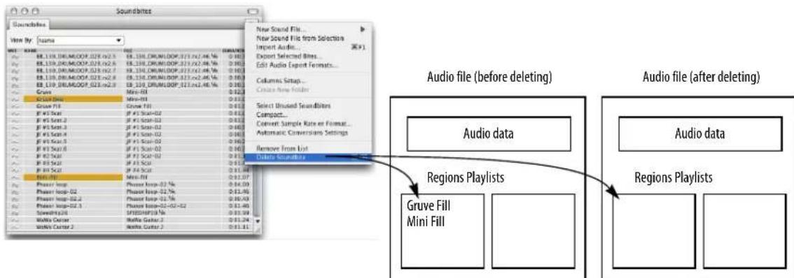
Figure 3-10: Deleting soundbites removes their corresponding region in the audio file. Just the region and its pointers are removed; not the actual audio data.
To select unused soundbites, choose Select unused soundbites from the Soundbites window mini-menu. All soundbites that are not being used in a track become highlighted in the Soundbites window list.
Deleting soundbites
The Delete command in the Soundbites window mini-menu removes currently selected soundbites from the list. In addition, the soundbite's corresponding region is removed from the audio file region list as shown in Figure 3-14 below (unless the region is being used as part of a playlist in the audio file).
Note that the Delete command will only delete the actual audio data when the last soundbite referring to an audio file is deleted. If you want to delete just a portion of the audio data from an audio file, use the Compact command. See “Compacting audio files” on page 58. If you do not want Digital Performer to remove the region from the audio file region list (because it is used in another Digital Performer project, for example), use the Remove from list command described in the next section.
Deleting soundbites that are currently being used in a track
If a soundbite you are deleting is being used in a track, Digital Performer presents a warning box as shown below.

Figure 3-13: Hold down the Option/Alt key while choosing Delete from the mini-menu to bypass this warning.
Removing soundbites from the soundbites list without deleting their corresponding region in the audio file
There may be times that you wish to delete a soundbite from the list, but you do not want to delete its corresponding region in the audio file region list as shown in Figure 3-14 on page 51. For example, the region might be part of a sequence in another Digital Performer project. In this situation, use the Remove from list command.
After this command severs the connection between the soundbite and the region in the audio file, you won't have access to the region unless you import it again. (See “Importing and exporting audio” on page 47.) Also, after removing a soundbite from the list, you cannot compact its audio data without first importing it and then deleting the soundbite. (See “Compacting audio files” on page 58 for more information.)
Deleting the last soundbite in an audio file
If you delete a soundbite, and it is the last soundbite belonging to a particular audio file, Digital Performer asks you if you wish to completely remove (delete) the audio file from the hard disk:

Remember, Digital Performer is cautious about deleting audio data: it never deletes audio data that is possibly being used in other files. Therefore, if an audio file has regions in its regions list, Digital Performer won't allow you to accidentally delete it.
Bypassing warning dialogs when deleting audio files
You can bypass warning dialog boxes by holding down the Option/Alt key while you choose Delete or Remove from list from the mini-menu. Digital Performer proceeds as if you answer Yes to the alerts.
Deleting an audio file that contains regions
If an audio file contains regions, but you are absolutely sure that you want to throw away the file, you can do so by dragging the file into the trash on the computer desktop.
Getting rid of unused soundbites after a session
After a recording session with Digital Performer, you can quickly get rid of all the soundbites that you did not use in a track as follows:
1 Choose Select unused soundbites from the Soundbites window mini-menu.
This highlights all soundbites that are not being used in a track.
2 Hold down the Option/Alt key and choose Delete from the Soundbites window mini-menu.
All of the highlighted soundbites are removed from the list, and their parent audio files are deleted from the hard disk.
Compacting audio files
The Compact command in the Soundbites window mini-menu deletes portions of an audio file that are not part of a soundbite and then closes the gaps between the leftover regions. For more information, see “Compacting audio files” on page 58.
DRAGGING AND DROPPING SOUNDBITES
You can “drag and drop” soundbites into the Track Overview, Sequence Editor, Event Lists and even the computer desktop (or any desktop window). To do so, grab the move handle of the soundbite as shown below in Figure 3-15 and drop it into the desired window.
In the Track Overview the soundbite is placed at the beginning of the grid segment you drop it into. If you hold down the Command/Ctrl key while dragging, the soundbite will "snap" to the end of the previous soundbite from the drop point or to the beginning of the track.
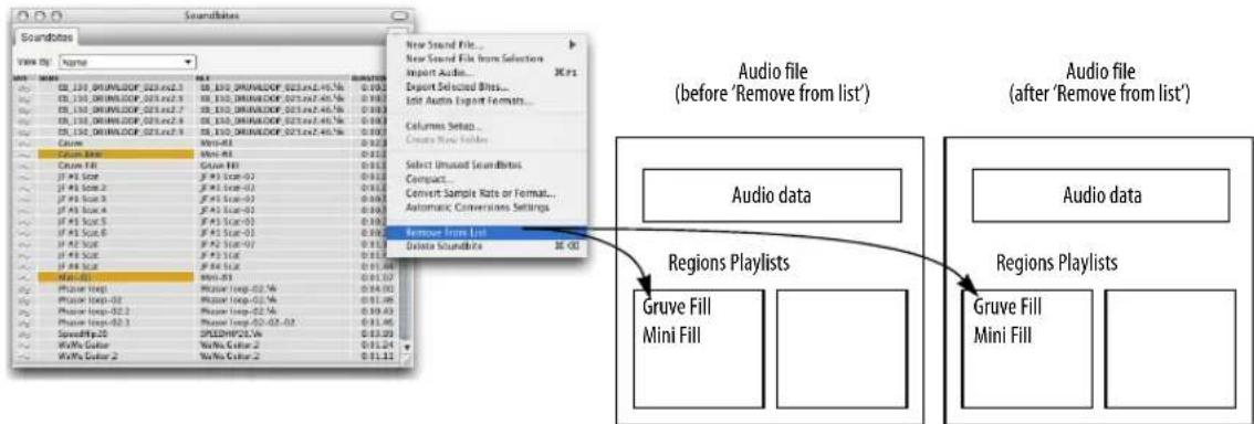
Figure 3-14: The Remove from list command leaves the region list in the audio file untouched. You can re-import the soundbites later, if desired.
In the Sequence Editor, the soundbite is placed where the cursor is located when you drop. If you hold down the Command/Ctrl key while dragging, the soundbite will "snap" to the end of the previous soundbite in the track from the drop point or the beginning of the track. For more information, see "Dragging and dropping audio into the Sequence Editor" on page 389.
In both the Track List and Sequence Editor, you can drag and drop a soundbite into the left-hand side of the window (into the Track List itself or into the left side of the Sequence Editor where the track information panels are displayed) to add a new track to the project and insert the soundbite into the new track. The soundbite is placed at its original timestamp, or, if there is none, at the beginning of the track.
In an Event List, the soundbite is placed end-to-end with the last soundbite at the bottom of the list. For more information, see “Dragging soundbites into the Event List” on page 446.
For more information about dragging and dropping soundbites to and from the desktop (to import and export them), see “Importing and exporting audio by drag & drop” on page 37.
WORKING WITH MULTIPLE SAMPLE FORMATS
Digital Performer can use 16-bit integer, 24-bit integer, and 32-bit floating point audio files together in the same project, without any conversions.
CONVERTING SAMPLE RATE/FORMAT
The Convert Audio File command in the Soundbites window mini-menu allows you to change the sample rate, sample format (bit depth), file format (AIFF, Broadcast WAVE, or Sound Designer II), or interleave format of an audio file or soundbite. Like Digital Performer's other file-based "constructive" DSP processes, these operations can occur in the background. For complete details, see chapter 77, "Audio File Conversion" (page 919).
AUTOMATIC CONVERSIONS
Digital Performer can automatically convert audio data wherever necessary to make it conform to the current project's sample rate, file format, interleave format and tempo. Because processing is initiated automatically and carried out via background processing (for lengthy operations), these auto-conversion features greatly streamline the process of importing audio quickly into your projects, or the process of converting the entire project to a

Figure 3-15: Dragging and dropping Soundbites into the Sequence Editor. Soundbites can also be dropped into other windows, such as Event Lists.
different sample rate, bit depth or tempo. For complete details, see “Automatic Conversions” on page 89.
RELOAD SOUNDBITE
Reload Soundbite (Audio menu) updates a soundbite to match its corresponding region in the audio file. For example, if you trim the edges of a region with other software, the Reload Soundbite command updates the soundbite in your Digital Performer project to use the new edge boundaries. This command is useful after using the Edit in Wavefor m Editor command (see below). For more information, see “Reload Soundbite” on page 652.
REPLACE SOUNDBITE
Replace Soundbite replaces a soundbite with a completely different region. For example, if you have inserted a soundbite called Riff in many places throughout your sequence, but later you record a better-sounding riff, you can quickly replace the old one with the new one using Replace Soundbite. For more information, see “Replace Soundbite” on page 655.
EDIT IN WAVEFORM EDITOR
You can edit audio files in Digital Performer's built-in Waveform Editor for Pencil tool editing of the waveform and other tasks. To open the Waveform Editor for an audio file, double-click any soundbite in the Soundbites window.
Also, if the “Update the Waveform Editor to the selection” preference is enabled and the Waveform Editor is in the Consolidated Window (see page 113), the Waveform Editor will automatically update to the soundbite you select in the Soundbites window.
For more information on the Waveform Editor, see chapter 44, “Waveform Editor” (page 525).
USE EXTERNAL WAVEFORM EDITOR
The Use External Waveform Editor option lets you choose a third-party waveform editor, such as BIAS Peak ™ , as your preferred waveform editor (instead of Digital Performer's own built-in waveform editor). For details, see “Use external waveform editor” on page 656.
VIEWING MORE SOUND FILE INFORMATION
To view more information for a soundbite or audio file, such as the length in samples, the creation or last edited date & time, Automatic Conversions settings, sync point, sampler loops, and more, use the Sound File Information window.
For details on the Sound File Information window, see "Sound File Information" on page 365.
CHAPTER 4 Content Browser
OVERVIEW
The Content Browser gives you immediate access to assets that you can quickly drag and drop into your Digital Performer project. Examples include audio files, loops, plug-ins, virtual instruments and clippings.
Quick Reference....55
Content Browser mini-menu....56
Opening the Content Browser ....56
Using the Content Browser 56
Auditioning audio clips 56
QUICK REFERENCE
Project: Provides access to audio files, bounces, clippings and other project-related content.
Places: Folders on your hard drive(s). Click the Add Place item to add a folder to the list. The folders can contain any content that is relevant to Digital Performer, including audio files, loops, etc.
Plug-ins: This section provides access to assets that are specific to plug-in operation, such as virtual instruments and plug-ins you have

Figure 4-1: The Content Browser.
installed in your system, plug-in presets (as clippings), and samples used by virtual instruments.
Clippings: Provides access to Digital Performer clippings. Click Add Clipping Group to add it as a folder to the list. For more information about the different types of clipping groups, see chapter 55, "Clippings" (page 705).
Preview pane: Shows information about the currently selected item.
Forward/backward buttons: Moves forward and backward through your browsing history.
Go up one folder level: Goes to the enclosing folder of the one you are currently viewing in the browser.
CONTENT BROWSER MINI-MENU
The Content Browser only has one mini-menu item:
Show Content Info: When checked, this command displays the Preview pane (Figure 4-1).
OPENING THE CONTENT BROWSER
To open the Content Browser as a separate window, choose Project menu>Content Browser, or press its keyboard shortcut, if you've already assigned one. To open it in a sidebar, choose it from any sidebar cell menu (Figure 10-5 on page 115).
USING THE CONTENT BROWSER
Use the Content Browser for quick access to assets...any items you might use as you work with Digital Performer. Use the Content Browser to navigate to a particular audio loop, plug-in, clipping, Mixing Board insert preset or any similar item and then drag and drop it into any Digital Performer window that accepts that type of item.
For example, you can drag and drop audio loops from the Content Browser into the Clips window or Sequence Editor. Or drag and drop plug-ins — or entire plug-in chains (as clippings) — into the insert section of the Mixing Board.
AUDITIONING AUDIO CLIPS
To audition audio clips in the Content browser, enable Audible Mode (“Audible mode” on page 337) and then click the item you wish to audition. Note that some audio file types may not support auditioning.
CHAPTER 5 Audio File Management
OVERVIEW
This chapter tells you:
■ Where audio files are stored on disk
■ How to manage the audio files associated with a Digital Performer project
■ How to get rid of unused audio
■ How to reclaim hard disk space using the Compact command
The Audio Files folder....57
Renaming audio files....57
Moving audio files....57
Working with multiple drives....57
Deleting audio files....57
Getting rid of unused audio ....58
Compacting an entire project....60
THE AUDIO FILES FOLDER
As explained in “Components of a DP Project” on page 23, each Digital Performer project includes an Audio Files folder (Figure 1-1 on page 23).
The Audio Files folder keeps track of all of the audio files for a Digital Performer project. In a new project, takefiles are placed in the Audio Files folder by default. You can record an entire Digital Performer session without concern for the location of the audio files you record because Digital Performer will automatically store them by default in this folder. However, audio files do not have to be located in this folder. For example, you might import an audio file into the project that is located on another hard drive. Or you might want to record audio on another hard drive that has much more free space on it. (See “Checking the current takefile location” on page 268.)
RENAMING AUDIO FILES
You can rename audio files at any time by editing the file name on the computer desktop or by Option/Alt-clicking its name in the Soundbites window. In either case, Digital Performer automatically updates the name in the other location so that they always match.
MOVING AUDIO FILES
You can freely move audio files to any location you want and Digital Performer will automatically keep track of them. You can even place them on a different hard drive. If you are not sure where an audio file is, and you would like to find out, click one of its soundbites in the Soundbites window and look at the information for the parent audio file in the Sound File Information window. If necessary, you can make the window larger to see the entire path.
If you copy a file onto another volume and delete the original, Digital Performer will not know about it and will ask you to find it.
WORKING WITH MULTIPLE DRIVES
Since Digital Performer does not care on which hard drive you record and store your audio files, you can store audio files for a single Digital Performer project on several different hard drives. This can help improve the overall disk performance of your system because it distributes the intensive disk accessing burden across more than one disk.
DELETING AUDIO FILES
You can delete audio files by dragging them into the trash or recycle bin. The only drawback to this method is that you can't view or audition the regions that the file contains to verify that you don't need them. If you want to inspect the
soundbites in the audio file before deleting it, use Digital Performer's Soundbites window. Open the Digital Performer file associated with the audio file (or import its soundbites into Digital Performer) and do the following:
1 View by file name (using the View by menu the top of the window).
This groups the soundbites together by audio file.
2 If you want to check the soundbites by listening to them, turn on the Audible Mode button (in the Control Panel) and click them.
3 Drag over their names to highlight them.
4 Choose Delete from the mini-menu and answer Yes when asked if you would like to delete the audio file.
As a shortcut, hold down the Option/Alt key when selecting the Delete mini-menu command to bypass the warning dialog.
GETTING RID OF UNUSED AUDIO
Digital Performer provides several simple techniques for permanently removing unused audio data from the hard drive. You can employ these techniques at any time to generate more free hard disk space. Just be aware that they permanently remove audio data, so be careful when choosing what to delete. The next few sections cover these techniques.
Selecting and deleting unused soundbites
The Soundbites window mini-menu has an item called Select Unused Soundbites. This command highlights all soundbites in the list that are not being used in any track in any sequence in the file. (For more information, see “Selecting unused soundbites” on page 49.)
You can delete the highlighted soundbites by choosing Delete from the mini-menu.
Compacting audio files
After a recording session, you may wish to get rid of all the data that ended up not being used in any of the tracks to reclaim significant amounts of free space on the hard disk. Compacting is a process that deletes portions of an audio file that are not part of a soundbite and then closes the gaps between the leftover regions.
As shown in Figure 5-1, the unused data between soundbites is removed, and the remaining soundbites are placed end to end. Compacting

flowchart
graph TD
A["Audio file before compacting: Soundbite A Soundbite B Soundbite C"] --> B["All unused audio gets removed."]
B --> C["Audio file after compacting: Soundbite A Soundbite B Soundbite C"]
Figure 5-1: Compacting removes all audio data that doesn't fall within an existing region. Depending on how much unused audio gets removed, this process can free up large amounts of space on the hard disk.
conserves disk space by removing unwanted data from within a file, while preserving data being used for soundbites.
You can compact all audio files at once or individually.
When compacting occurs, there is only one criterion for determining if data is thrown out:
Is the data part of a region in the audio file's region list?
If the data is part of a region in the audio file's region list, it is not deleted.
If the data is not part of a region, it is deleted.
The key to successfully compacting a file is to make sure that the region list in the audio file contains regions that you want to keep, and only those regions that you want to keep.
How do you do this? With the Soundbites window. If you delete a soundbite that you want to discard, Digital Performer removes the soundbite's corresponding region in the audio file's region list (see "Deleting soundbites" on page 50), and the remaining audio data is deleted when compacted. Conversely, soundbites that are not deleted are not compacted.
If any audio data in the audio file is being used by other Digital Performer files, it is not deleted by these commands as long as you have not deleted the region from the audio file's region list with Digital Performer or other sample editing software. Digital Performer does not delete any regions in the audio file, even if they are not used in the currently open Digital Performer file.
Since compacting results in the erasure of audio data on the hard disk, and possibly very large amounts of audio data, this operation may take a few moments, depending on how much audio data is being removed.
To compact one or more audio files:
1 (Optional) Choose Select unused soundbites from the Soundbites window mini-menu.
This highlights all of the soundbites that are not being used in any track in the file. These are likely candidates for disposal.
2 Delete all soundbites from the Soundbites window that you want to discard using the Delete command in the mini-menu.
If necessary, you can audition ones that you aren't sure about using Audible mode. To delete the soundbite, highlight its name and choose Delete from the mini-menu. Don't use the Remove from list command—it will not remove the regions from their audio files.
3 Highlight a soundbite from each audio file that you wish to compact.
If you want to compact all the audio files, choose Select All from the Edit menu (or press Command/Ctrl-A).
4 Choose Compact from the Soundbites window mini-menu.
The compacting operation may take some time. After compacting, an alert box informs you that disc space won't actually be reclaimed until after you flush the undo history, which permanently discards the data removed by the compact operation. If you click Don't Flush, then the compacted data is preserved in the undo history, and you'll still have a chance to recover it if you change your mind. If you click Flush, then the
undo history is flushed, and the data removed by the compact operation is permanently discarded (and therefore becomes unrecoverable).
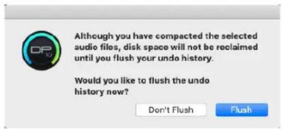
Compacting won't work if...
There is one condition in which compacting won't do the right thing for you: if the data you want to get rid of exists as a region in the audio file and there is no corresponding soundbite for it in Digital Performer's Soundbites window. This situation can arise if:
■ the region wasn't created in the current Digital Performer file
OR
- at some point you highlighted the region and chose the Remove from list mini-menu command, which removes the soundbite name from the Soundbites window but doesn't delete the corresponding region from the audio file region list.
The first case is rare. It isn't often that you want to delete a region from anywhere other than the file it was first created in. Otherwise, the region is probably there for a purpose — and therefore you don't really want to delete it.
To avoid the second case, only use the Remove from list command with soundbites you are absolutely sure that you will never want to discard. Otherwise, they might take up hard disk space without you even knowing it. If this is the case, import the region into Digital Performer and then delete the soundbite with the Delete command.
COMPACTING AN ENTIRE PROJECT
The Compact Project command (File menu) provides a unified, comprehensive way to discard unused audio, flush the undo history and reduce a project's overall size on disk. Compact Project is specially designed to eliminate the items you choose in the dialog in the optimum order to achieve maximum efficiency in compacting the project.
You can use this feature at any time you wish during the course of a project, but it flushes the entire undo history, so beware. This feature is particularly useful for project archiving, as it can significantly reduce the amount of disk space used by the project, making it much easier to archive.
Warning: Compact Project affects the original project, and it permanently discards data that is flushed during the compacting process.

Figure 5-2: The Compact Project command.
CHAPTER 6 Project File Interchange
OVERVIEW
Digital Performer can exchange projects with other applications using industry-standard formats such as OMF, AAF, and Final Cut Pro XML. Digital Performer's support for import and export of these formats is built-in — no additional software is needed (though the other application you're interchanging with may require additional plug-ins or add-ons to import the files).
Introduction to OMF and AAF....61
Importing OMF/AAF files....61
Exporting OMF/AAF files ....62
Final Cut Pro XML interchange....67
INTRODUCTION TO OMF AND AAF
OMF interchange (Open Media Framework Interchange, sometimes abbreviated as OMFI) and AAF (Advanced Authoring Format) are file formats used to interchange projects and their audio files between different applications.
Digital Performer has the ability to import and export AAF 1.0 and OMF 2.0 session files for interchange with other OMF and AAF-compliant applications. You should be able to exchange both AAF and OMF sessions with any application that supports AAF (1.0) or OMF (1.0 or 2.0) session interchange. Digital Performer's implementation has been mostly tested with Pro Tools, Logic Pro, Cubase and Avid Xpress.
IMPORTING OMF/AAF FILES
OMF and AAF files can be opened like a regular Digital Performer project:
■ Using File menu > Open
■ Double-clicking the file on your computer desktop
■ Dragging to the Digital Performer dock icon
■ Dragging to the Chunks window
When you open an OMF or AAF file, you will be prompted to choose a project name and location for the project files. Any audio files which need to be extracted (such as with OMF or AAF files containing embedded audio) will be copied to the project's Audio Files folder.
General recommendations for import
First and foremost, please read all documentation regarding OMF and AAF interchange for the application you will be interchanging with. In many cases, a broad choice of compatible settings are available; understanding those settings will assist you in creating the best OMF or AAF file for use in Digital Performer.
Keeping your files organized and properly labeled prior to exporting will make interchange much easier —pfiles will have descriptive names and you won't need to worry about missing files. However, note that some applications may rename audio files when exporting as OMF or AAF.
Guidelines for creating OMF and AAF files for use in Digital Performer
■ Digital Performer can import OMF and AAF files using WAVE, AIFF, Sound Designer II, or embedded audio. Digital Performer does not import MXF audio.
■ Digital Performer can import OMF & AAF files using 16 and 24 bit audio.
■ Video files embedded in or referenced by OMF and AAF files are ignored when imported into Digital Performer.
- Digital Performer can accept OMF or AAF files at any of the frame rates Digital Performer can use as its project frame rate: 23.976, 24, 25, 29.97 (drop & non-drop), and 30 (drop & non-drop). Files at HD frame rates of 50, 59.94 (drop & non-drop), and 60 (drop & non-drop) can also be imported, but the frame rate is set to the corresponding half rate. Files at other frame rates can also be imported, but their frame rates are not supported and you must choose one of Digital Performer's supported frame rates.
- When exporting OMFs for use in Digital Performer, choose OMF 2.0 over 1.0 whenever possible. If no choice is provided, check the application's documentation to find out which OMF version is exported. Though OMF 1.0 files will generally import into Digital Performer without issue, OMF 2.0 is strongly recommended for the most robust OMF interchange.
- Fades can be saved as part of the OMF/AAF file; however, different host applications may handle this fade data differently (including ignoring them entirely). To ensure consistent fades between hosts, choose to export the fades as separate regions. This is somewhat less flexible, as those fades are now regular audio regions, but it ensures consistent results. Most hosts will include enough extra audio around the abutting regions to allow you to delete the fade and trim out the original audio regions, should you wish to change your fade. Check your application's documentation to see how it handles fades. If it supports fades as OMF/AAF effects, make a short test file to ensure that they translate into Digital Performer as intended.
Remember, OMF and AAF files do not transfer any MIDI data; in addition to notes and controllers, components such as tempo changes and markers may be saved as MIDI data. If you need to transfer them as well, export a Standard MIDI File in addition to your OMF or AAF file.
EXPORTING OMF/AAF FILES
To export an OMF or AAF file, choose Save As or Save a Copy As from the File menu, and then choose OMF Interchange or AAF Interchange from the Format menu (Figure 6-1). The OMF/AAF Export Options window appears (Figure 6-2).

Figure 6-1: Digital Performer can import and export OMF and AAF files.
OMF/AAF export options
Other applications support varying degrees of OMF and AAF interchange support, depending on the application and version. For example, some older versions of Pro Tools only support OMF files with 16-bit audio, but newer versions support 16- or 24-bit. Similarly, other applications that support OMF and AAF interchange also have varying degrees of support for these interchange files formats. As a result, Digital Performer provides numerous interchange options to give you the broadest possible compatibility across the board. Here is a brief explanation of the OMF/AAF export options shown in Figure 6-2.

Figure 6-2: The OMF/AAF Export Options.
The 'Enforce Compatibility' options
The Enforce options at the top of the window enable or disable various settings below so that you won't inadvertently enable an option that is not supported by the third-party application. For example, Pro Tools does not support clip-based pan; therefore, when you chose the Enforce Pro Tools compatibility check box at the top of the window, the Export clip-based pan check box at the bottom of the window becomes grayed out (unavailable).
Pro Tools version 9 and later can import OMF and AAF files without additional tools, but earlier versions require DigiTranslator (a separately purchased add-on). For further information, refer to your Pro Tools documentation or contact Avid.
References existing audio files
Reference existing audio files will reference the existing audio files in the current location; it does not create new audio files (with some exceptions – see below). Choose Reference existing audio files if you want the OMF or AAF file to refer to the same set of audio files on disk as the Digital Performer project that you are exporting from. This option saves disk space because it does not duplicate audio data. Because the Digital Performer Project and OMF/AAF file refer to the same set of audio, use this option when you are making permanent (“destructive”) changes to the audio data in the audio files that you would like to be reflected in both Digital Performer and the program you are interchanging with. For example, you might be removing clicks and pops, normalizing, etc. It can also help to simply save disk space when you are interchanging with another application on the same computer.
The References existing audio files option will be unavailable if:
- You've chosen the Quantize edits to frame boundaries option, which requires you to use the Consolidate audio files option.
- Your project contains Sound Designer II audio files and you are exporting as AAF (as AAF does not support Sound Designer II audio files).
- Your project contains 32-bit floating point audio files.
- Your project contains a mix of interleaved and deinterleaved files, or a mix of mono files and interleaved stereo files. All audio files must be interleaved OR deinterleaved OR a mix of deinterleaved and mono to be exported as references.
Even when using Reference existing audio files is permitted, note that some applications may not support all audio file format combinations that Digital Performer does, such as mixed file formats (e.g. WAVE and AIFF) or mixed sample formats (e.g. 16 and 24 bit). Check your target application's documentation, and if necessary convert the file format or sample format of your files before exporting as OMF or AAF, or use Copy all audio files or Consolidate audio files instead.
Reference existing audio files exceptions
When the Reference existing audio files option is selected, Digital Performer will try to reference the existing files if possible. However, there are some cases where your choices for the other export options will force the creation of new audio:
- When the export format (OMF or AAF) does not support audio files in the file format of those in your project, any files in non-supported formats are exported as audio files. OMF supports AIFF, WAVE, and SDII, whereas AAF supports only AIFF or WAVE. So for example, if you are exporting as AAF and your Digital Performer project contains mostly WAVE files, but also contains some SDII files, Digital Performer will export references to the WAVE files (i.e., they will not be copied) but the SDII files will be converted to WAVE files.
■ When converting from 24-bit to 16-bit, the converted files are exported as audio files.
■ When using Export fades as precomputed regions, the fade regions are exported as audio.
■ When additional audio must be created, the new audio will be embedded (when exporting as OMF) or created as additional WAVE files (when exporting as AAF).
Copy all audio files
Choose Copy all audio files to make a completely self-contained copy of the entire project, including all audio files. All audio files that are listed in the Soundbites window are included, even if they are not used in any tracks in the project. This option is ideal for transferring the project to another hard drive or computer as it ensures that all associated audio files are “collected” and included in the interchange document. When you use this option, the exported project will have no references to your original project. This makes it completely independent, and it will not be affected by any changes made to the original project. The Copy all audio files option is grayed out if you've chosen the Quantize edits to frame boundaries option, which requires you to use the Consolidate audio files option (explained in the next section).
Consolidate audio files
Like Copy all audio files above, the Consolidate audio files option leaves no references to the original project and instead copies the original audio. However, it only copies audio that is actually used in soundbites. Portions of audio files that fall outside of soundbite boundaries are not copied. This option is useful because it can save a significant amount of disk space in some projects. If you are looking to economize on the project size, perhaps for archival purposes, this option is a good choice.
The Handle Size option specifies the amount of extra audio (in milliseconds) to include before and after each soundbite. This is useful if you will be trimming (edge editing) the soundbites in the destination application.
Embed audio data in OMF
This option applies to audio being copied during the export operation, if any.
Choose Embed audio data in OMF file to place the copied audio directly into the OMF file itself. This makes a single, completely self-contained document that consists of a copy of the entire project, including all audio files. See “Copy all audio files” on page 64 and “Consolidate audio files” on page 64 for further information about what audio gets copied and when this option is useful.
Export audio data as Sound Designer II/AIFF/WAVE files
These options apply to audio being copied during the export operation, if any. Choose the desired file format for the audio files being copied to the AAF or OMF project.
The Sound Designer II file option is disabled (not available) when you are exporting to an AAF file because AAF files do not support Sound Designer II files. In general, exporting as WAVE or AIFF is recommended.
'Export fades as' options
The Export fades as OMF/AAF effects option produces fades and crossfades that can be fully modified in the target application after the transfer, if desired. The Export fades as precomputed regions option renders each fade as an audio region, preserving the exact nature of the fade or crossfade as it was programmed in Digital Performer but rendering it un-modifiable. For example, if you like the way your fades and crossfades sound already in Digital Performer, and do not need to further modify them in the target application, use this option.
If you've chosen the Quantize edits to frame boundaries option, then the Export fades as OMF/AAF effects option is not available (grayed out).
Exporting 24-bit audio
The Convert 24 bit audio to 16 bits option converts all 24-bit audio in the project to 16-bit audio. Most third-party audio applications support 24-bit audio, so it is recommended that you enable this option only if you must. If you are exporting 24-bit audio and wish to maintain this bit depth, choose Export 24 bit audio directly.
One notable 16-bit-only example is OMFTool/DigiTranslator 1.0. If you intend to open the OMF file in DigiTranslator 1.0, enable the Convert 24 bit audio to 16 bits option.
Export sample-accurate edits/Quantize edits to frame boundaries
For Avid Xpress and other applications that require OMF/AAF files to specify all timing in SMPTE time code frames, choose Quantize edits to frame boundaries. Digital Performer's current frame rate setting (Setup menu>Frame Rate) is used. This frame rate setting must match the frame rate in the Avid Xpress session into which you will import the OMF/AAF file.
Also, when using the Quantize edits to frame boundaries option, you are forced to use the Consolidate audio files and Export fades as precomputed regions options. All of your soundbites will get trimmed so that they start and end on frame boundaries. To maintain timing and ensure that all audio is properly included, Digital Performer then generates one-frame audio regions placed before and after the trimmed soundbite, containing the audio that was trimmed.
For all other applications (that don't require frame-based timing), choose Export sample-accurate edits. Consult the documentation for your editing application to determine if it requires frame-based timing for audio.
Export clip-based volume/pan
Because the OMF and AAF interchange formats support a clip-based automation model, automation data between clips is lost when exporting, but automation data within the boundaries of every audio region is preserved during transfers.
The Export clip-based volume and Export clip-based pan options determine whether volume and/or pan automation data will be included in the resulting OMF or AAF interchange document.
If the Enforce Pro Tools compatibility or Enforce Logic compatibility options are checked, then the Export clip-based pan option is grayed out because Pro Tools and Logic do not support pan automation interchange via OMF or AAF.
If you are exporting an OMF file intended for use with DigiTranslator 1.0, leave both options unchecked as these options are not supported by DigiTranslator 1.0.
Export original timestamps
Check the Export original timestamps option to include the original timestamps in each audio file. If your destination application does not support them, you can turn them off. For a complete explanation of timestamps, refer “Timestamps” on page 651.
If you are exporting an OMF file intended for use with DigiTranslator 1.0, leave this option unchecked as this option is not supported by DigiTranslator 1.0.
Export soundbite names
Check the Export soundbite names option to export each audio region with its given soundbite name in Digital Performer.
Export all sequences
If the Digital Performer project you are exporting has two or more sequences, check the Export all sequences option if you wish to include all sequences, even the ones that are not currently play-enabled. This option is grayed out if you are enforcing any compatibility modes other than Avid Xpress.
Export all takes
If the tracks in the sequences you are exporting have multiple takes, check the Export all takes option if you wish to include them in the export operation. Each take is saved in the OMF/AAF export document as a separate track.
OMF/AAF export summary
Here is a summary of OMF and AAF export:
OMF/AAF
| export option | Summary |
| When exporting AAF | Disables Reference existing audio files (when using SDII files)Disables Export audio data as SDII files |
| Pro Tools compatibility | Disables Export clip-based panDisables Export all sequencesDisables Export all takes |
| Logic compatibility | Disables Export fades as OMF/AAF effectsDisables Export clip-based panDisables Export all sequencesDisables Export all takes |
| Avid Xpress compatibility | Requires Quantize edits to frame boundaries |
Quantize edits to Requires Consolidate audio files
frame boundaries Requires Export fades as precomputed regions
General OMF/AAF export recommendations
If the application you are interchanging with is not covered by the OMF/AAF Export dialog's Enforce compatibility modes, use the following generic settings as a starting point. There are two basic groups of OMF/AAF settings: those intended for DAWs (digital audio workstations, such as Digital Performer), and those intended for NLEs (non-linear video editing applications, such as Final Cut Pro).
Exporting to DAWs
Digital Performer's default settings are a good starting point for interchange with any DAW. To return to the default settings, press the Default button in the OMF/AAF Export Options window at any time. The default settings are:
■ Enforce Pro Tools compatibility
■ Enforce Logic compatibility
■ Copy all audio files
■ Export audio as WAVE or AIFF
■ Deinterleaved audio (interleaved unchecked)
■ Export 24 bit audio directly
■ Export fades as pre-computed regions
■ Export sample-accurate edits
■ Export soundbite names
Exporting to NLEs
Non-linear video editing applications, such as Avid Xpress and Final Cut Pro, require that edits are aligned with frame boundaries; this means that the Quantize edits to frame boundaries option must be enabled, which in turn forces Consolidate audio files and Export fades as precomputed regions.
Digital Performer's Avid Xpress compatibility mode is the recommended starting point for interchange with any NLE:
■ Consolidate audio files, 1000 ms handle
■ Export audio as WAVE or AIFF
■ Deinterleaved audio (interleaved unchecked)
■ Export 24 bit audio directly
■ Export fades as pre-computed regions
■ Quantize edits to frame boundaries
■ Export soundbite names
Using embedded audio
In the above recommendations, we recommend using copied or consolidated WAVE or AIFF audio. Depending on the target application, you may also be able to use embedded audio, but it is recommended that you do not embed the audio if you are unsure.
If there is a problem importing the file when the audio is embedded, you may be unable to open the file or access its associated audio; but if you use copied audio, in a worst case scenario you may be able to manually re-create the project using the timestamped audio files. Check with your target application's documentation to see if embedded audio is permitted. You may also want to create a small test file to verify that it works before sending large projects when time is sensitive.
OMF version
Digital Performer always creates OMF version 2.0 files.
FINAL CUT PRO XML INTERCHANGE
Digital Performer supports advanced session interchange with Final Cut Pro (FCP) Version 5.0 or later via Final Cut's XML session interchange features. These features allow you to produce a full multitrack music score — or even a complete soundtrack including sound effects, foley, dialog and music — completely in Digital Performer, even as picture is being edited in Final Cut Pro, either on a different computer or the same computer as Digital Performer.
Final Cut Pro 6.0 or later is recommend for this feature.
XML interchange overview
In Digital Performer, there are two commands in the File menu for performing session interchange with Final Cut Pro:
Import Final Cut Pro 7 XML
The Import Final Cut Pro 7 XML command opens a modeless window used to import sequences from Final Cut Pro using either an XML file or direct communication with the Final Cut Pro application running on the same computer.
Export Final Cut Pro XML
The Export Final Cut Pro XML command opens a modal dialog used to export sequences to either a Final Cut Pro XML file or directly to the Final Cut Pro application running on the same computer.
Overall workflow
When picture edits are made in Final Cut, the FCP editor can export an XML file that describes all current edits, which the Digital Performer
composer/editor can simply import, to then compare and conform all music and audio tracks to the latest picture edits. All changes are displayed in Digital Performer's Import Final Cut Pro 7 XML window, which provides a complete, detailed list of every new picture edit. Double-click any edit in the list, and Digital Performer scrolls to and highlights the location of the edit in the Sequence Editor time line. The highlight shows a blue border (old position) and red border (new position) for each picture edit. The Digital Performer composer/editor can then adjust their conductor track, audio data and/or MIDI data as necessary to conform to the new edit, snapping edits to the vertical red line if necessary.
If Digital Performer is running on the same computer as Final Cut Pro, the Export Final Cut Pro XML command sends all tracks (and all sequences) in the current Digital Performer project to the project currently open in Final Cut Pro (or any FCP file on disk, if desired), allowing easy transfer of all work done in Digital Performer into Final Cut at any point during the production process, from previewing dailies to final conform and export from Final Cut.
The Final Cut Pro XML Export Dialog
The Final Cut Pro XML Export dialog (Figure 6-3) exports all sequences (excluding V-Racks and Songs) in the currently open Digital Performer project. It does so either to an XML file that you specify, or to an invisible temporary XML file, which is used to transfer the information directly to Final Cut Pro running on the same computer.
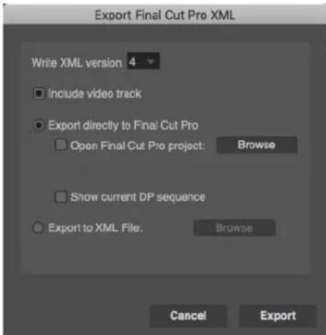
Figure 6-3: Final Cut Pro XML Export dialog.
Video and audio files
The XML file format only makes references to audio and video files stored on your hard disk. It does not copy the audio or video data into the XML file (which is just a text file). Therefore, if you want to send a Final Cut Pro XML file to a colleague running Final Cut Pro on a different computer, and your colleague doesn't already have the media files, you need to send the audio and video files separately, along with the XML file.
Conforming path names
If the location of the media files on the destination computer does not match their relative location stored in the exported XML file, then the path names of the audio and video files embedded in the XML file must be edited to match their location on the destination computer's hard drive. This can be done with any standard text editor, as the XML files are simply text files. The file path names in the XML file look like this (note that spaces are represented by “%20”):
XML version menu
The Write XML version menu (Figure 6-3) lets you choose to export an Apple XML Interchange Format version 4 file or an Apple XML
Interchange Format version 3 file. Always use version 4 unless you are sending the XML to Final Cut Pro Version 5. XML Version 4, used by Final Cut Pro Version 6 and later, is a more robust file format that can identify audio and video clips by ID and recognize them even after they have been reordered. This more advanced format provides much better support for Digital Performer's XML Compare feature (explained later in this chapter).
Include video track
When checked, the Include video track option (Figure 6-3) creates a Final Cut Pro video track in each sequence that references the movie associated with that sequence in Digital Performer.
Export to XML File
When the Export to XML file option (Figure 6-3) is enabled, the results of the export are put into an XML file of your choosing. Click the Browse button to choose a location and filename for this file, after which the name of the file will appear in the read-only file name box below the radio button. Or, you can just click Export, and you will be prompted to specify your output file if you have not already done so.
Export directly to Final Cut Pro
When the Export directly to Final Cut Pro option (Figure 6-3) is enabled, Digital Performer exports to an invisible temporary XML file, which it then sends directly to Final Cut Pro for import. This works only if Final Cut Pro is currently running on the same computer. If neither of the check boxes below this radio button are enabled, when you click on the Export button, the following will happen:
- Final Cut Pro comes to the foreground.
-
Final Cut Pro creates a new untitled project, and fills it with sequences with the same names as the incoming Digital Performer sequences.
-
A bin named Master Clips from DP is created to contain all audio files referenced by the Digital Performer sequences. If you enabled the Include video track option, the referenced movie files also appear in this bin.
Open Final Cut Pro project
The Open Final Cut Pro project sub-option (Figure 6-3) modifies how the Export directly to Final Cut Pro" option works. When it is enabled, you are asked to select a Final Cut Pro project document (a file ending in .fcp). You can use the Browse button to make your selection immediately, or you will be prompted to do so if you have not already done so when you click the Export button. After you have chosen a .fcp file, Final Cut Pro will first open that project document and then import the sequences from Digital Performer into that document. It will not overwrite existing sequences in the Final Cut Pro document; instead, it will make new ones. If the chosen Final Cut Pro project is already open in Final Cut Pro, it will just be brought to the foreground and used as the receiver of the incoming sequences from Digital Performer. (Note: the Final Cut Pro project will not be reverted to the state saved on the hard disk beforehand.) This is useful if you have several Final Cut Pro projects open at the same time, some with unsaved changes.
Show Current DP Sequence
The Show Current DP Sequence option (Figure 6-3) displays the imported current (play-enabled) Digital Performer sequence in Final Cut Pro after the export operation.
The Final Cut Pro 7 XML Import Window
The Final Cut Pro 7 XML Import window (Figure 6-4) allows you to import sequences from Final Cut Pro into Digital Performer, and to compare different versions of Final Cut Pro sequences. The compare feature can even analyze changes made to video and audio clips in Final Cut
Pro sequences without the need to import anything. These features allow you to conform a Digital Performer project to the current version of cues in a Final Cut Pro project.

Figure 6-4: Final Cut Pro 7 XML Import window.
Import from XML File
The Import from XML File option (Figure 6-4) lets you import a Final Cut Pro 7 XML file that already exists on your hard disk. Use the Browse button to locate the file you want to use, or just click the Import button and you will be prompted to choose an XML file. After you have done so, the file name appears in the read-only box below and can be used again the next time you want to import.
Import directly from Final Cut Pro
The Import directly from Final Cut Pro option (Figure 6-4) lets you import directly from the Final Cut Pro application, which must be currently running on the same computer. When using this option, you must specify a Final Cut Pro project file (ending in .fcp) that you wish to import from. The Final Cut Pro project file need not be currently open in Final Cut Pro — if necessary, Digital Performer will first open it in Final Cut Pro and then do the import. Use the Browse button to locate the Final Cut Pro project file that you wish to use. If that project is already currently open in Final Cut Pro, then you will be importing the current state of that project in Final Cut Pro — including any unsaved changes.
Include video
When the Include video option (Figure 6-4) is enabled, Digital Performer searches for the first movie clip in a video track for each imported Final Cut Pro sequence. If it finds one, it will install it as the movie associated with that Digital Performer sequence.
Include Audio
When the Include Audio option (Figure 6-4) is enabled, Digital Performer creates audio tracks that duplicate any Final Cut Pro audio tracks that it finds in each imported sequence.
Replace sequences
When the Replace sequences option (Figure 6-3) is enabled, Digital Performer replaces any sequence in the currently open Digital Performer project with an imported sequence that has the same uuid tag, which is a unique identifier applied to each sequence by Final Cut Pro. To see the uuid tag for any sequence, export an XML file from Final Cut Pro and look for a line similar to what is shown below, usually located just after the sequence id line:
To see the uuid stored in Digital Performer for a sequence, export a Final Cut Pro XML file from Digital Performer and inspect the same line.
Add new sequences
When the Add new sequences option (Figure 6-4) is enabled, Digital Performer creates new sequences for the imported Final Cut Pro sequences, even if an existing sequence in the current Digital Performer project has the same uuid as an incoming one.
Missing media files
If a media file cannot be imported, you will be warned. This may be for one of three reasons:
- The path could be incorrect on the host machine, and therefore DP can't find the media file
- The media file could have an unsupported format (meaning DP can't play it and can't convert it)
■ The media file could be in a format that DP understands, but cannot play natively.
These three conditions are now reported with alerts during the import process, along with information about the offending file. You'll see a warning dialog like the one shown below:
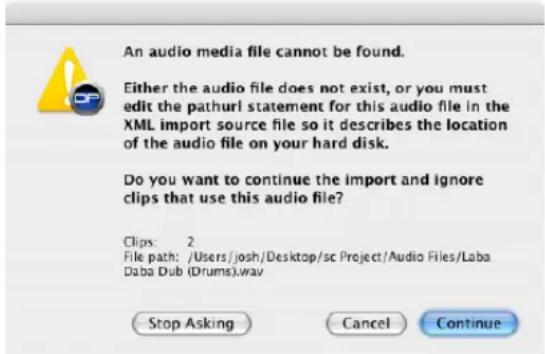
Figure 6-5: The Final Cut Pro 7 XML Import warning dialog.
You can choose one of these options:
Continue: Ignores the file and continues importing
Stop Asking: Ignores the file and continues importing, suppressing any future warnings during this import
Cancel: Cancels the entire import process
Comparing imported Final Cut Pro sequences
The Compare Import Source To section of the Final Cut Pro 7 XML Import window (Figure 6-4) allows you to compare sequences to see what changed. The first set of sequences that are being compared (the newer version) is specified in the left side of the window (the "Import Source"). The second set of sequences being compared (the older version) is determined by the options in the right side of the window, described in the next few sections.
Compare Import Source To: XML file
When the Compare Import Source to: XML file option (Figure 6-4) is enabled, you select an XML file that contains a description of the sequences you want to compare to. Use the Browse button to locate the XML file on your hard disk. A typical workflow is to export each version of a changed project from Final Cut Pro to an XML file, and save each file on disk as a change history. To compare any two such files, simply set the Import source to a newer XML file and the Compare Input Source To: XML file to an XML file that holds an older version of the sequences. Then click on the Compare button to see a list of differences in the bottom section of the import window.
Compare Import Source To: Last imported XML When the Compare Imported Source To: Last Imported XML option (Figure 6-4) is enabled, Digital Performer will compare the Import source to whatever Final Cut Pro XML data was last imported. This option works for the current Digital Performer session only; if you quit Digital Performer and start it up again, the last imported XML file will be forgotten.
Compare Import Source To: Current DP project When the Compare Imported Source To: Current DP project option (Figure 6-4) is enabled, Digital Performer will compare the Import source to the sequences in the currently open Digital Performer project. This option is convenient if you want to compare the current state of audio clips in Digital Performer with the state of audio clips in Final Cut Pro. When you use this option, however, the current Digital Performer project will have at most only one video clip per sequence. When compared to a Final Cut Pro XML source with many video clips, this option will likely produce a lot of
messages about missing video clips. Therefore, this option is most useful when comparing XML sources to see how audio changed, not how video changed.
If your Import Source is currently set to Import directly from Final Cut Pro (Figure 6-4), you will be comparing to the current state of a Final Cut Pro project in the Final Cut Pro application, including any unsaved changes that have been made to that project in Final Cut Pro.
Viewing comparison results
After you have chosen an Import Source and a Compare To source (Figure 6-4), click the Compare button to produce a detailed comparison. The scrolling list in the bottom of the XML import window fills with a list of differences between the compared sequences (Figure 6-6). Each portion of the list can be collapsed or expanded in order to show only those changes that you are interested in. Note that when you do a Compare, no sequences are imported into the current Digital Performer project. You can use the Compare function as a way to “pre-flight” changes in a Final Cut Pro project before you decide whether or not you want to import those changes. Or, you can use the Compare function to see what changes were made to non-importable video tracks in Final Cut Pro, so you can make corresponding conform edits to your Digital Performer audio tracks.

Figure 6-6: The XML comparison results list.
Click the disclosure triangles in the left column to show or hide portions of the comparison report. If you Option/Alt-click on a triangle, all of the triangles will open or close.
| Changes for Project "Cane Final Cut" | |
| ✓ Changes for Sequence "Sequence 1". | |
| ✓ Video changes: | |
| ✓ Track 1: | |
| ✓ Clip 4: | |
| Duration changed - Old: 64, New: 43. | |
| End time changed - Old: 3518 (1:28:26:14, 55(1)045), New: 3497 (1:28:25:16, 54(3)374). | |
| ✓ Audio changes: | |
| ✓ Track 1: | |
| ✓ Clip 4: | |
| Duration changed - Old: 64, New: 43. | |
| End time changed - Old: 3518 (1:28:26:14, 55(1)045), New: 3497 (1:28:25:16, 54(3)3574). | |
| ✓ Track 2: | |
| ✓ Clip 4: | |
| Duration changed - Old: 64, New: 43. | |
| End time changed - Old: 3518 (1:28:26:14, 55(1)045), New: 3497 (1:28:25:16, 54(3)3574). | |
| ✓ Track 3: | |
| Start Time changed - Old: empty track, New: 3275 (1:28:16:10, 51(1)428). | |
| End Time changed - Old: empty track, New: 4205 (1:28:35:04, 65(4)036). | |
| Number of Clips changed - Old: 0, New: 1. | |
| ✓ New Clip: | |
| Clip was added - Start time: 3275 (1:28:16:10, 51(1)428), End time: 4205 (1:28:55:04, 65(4)036). | |
Figure 6-7: Option/Alt-click a disclosure triangle to open or collapse all.
Inspecting a change
If you click on any entry in the comparison report (Figure 6-8), the corresponding time regions will be highlighted in Digital Performer's Sequence Editor (Figure 6-9). If you wish to highlight all changes for a sequence, click on the topmost entry named Changes for Sequence 'SequenceName'. When you click an entry in the list, the Sequence Editor highlights all changes contained within that list entry, even if some of those changes are currently hidden by disclosure triangles. You can select only one item in the comparison report list at a time, but it is permissible to have no selection at all. You may also use the Up and Down Arrow keys to step through the list of changes. As each list item containing a start or end time change is highlighted in the list, Digital Performer scrolls the Sequence Editor to the first highlighted time. Similarly, if you double-click a list entry containing a start or end time change, Digital Performer scrolls to the time of the first such change.
Here's an example. Suppose you select the following change in the comparison report:
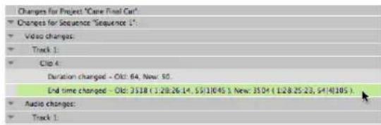
Figure 6-8: Selecting a change in the comparison report list.
This results in a gray highlighted area in the Sequence Editor (Figure 6-9). To make the gray highlight go away, deselect the change line in the comparison report list by Shift-clicking it, or close the Import Final Cut Pro 7 XML window entirely. To select the gray highlighted change area, use the I-beam tool on a track; your drag gesture will snap to the edges of the gray highlighted area. Shift-click other tracks to extend the selection to those other tracks as well.
The gray highlighted region has a blue vertical line on one side and a red vertical line on the other side. The red line indicates the new position of a clip edge in the Import Source (newer) sequence, and the blue line indicates the original position of the same clip edge in the Compare To (older) sequence. In an XML comparison, blue lines correspond to original (old) positions — the positions in the Compare To sequence. Red lines correspond to changed (new) positions — the positions in the Import Source sequence.
Figure 6-9 is displaying the change range for a video edit to a video track that was not even imported into Digital Performer. As indicated by the placement of the red and blue lines, this video clip was shortened in Final Cut Pro because the change highlighted in the comparison report (Figure 6-8) reports that the End time changed and the new (red) position is to the left of the old (blue) position. To conform the audio to this change in video, we could move the end of a corresponding soundbite to the position of the red line, which is the new end of that video clip. If we edge edit the soundbite and hold down the Command/Ctrl key, the end of our soundbite snaps to the red and blue lines at the edges of the gray highlighted area. Similarly, when dragging a soundbite, if you do not hold down the
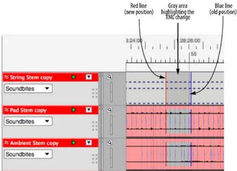
Figure 6-9: Inspecting an XML comparison change in the Sequence Editor.
Command/Ctrl key, the beginning of the soundbite snaps to the red and blue comparison range lines.
Volume and pan information
Final Cut Pro allows you to automate volume and pan settings within each audio clip (what Digital Performer would call a soundbite). Final Cut Pro does not support track automation of volume or pan, independent of the clips in the track. Final Cut Pro allows a maximum +12 dB boost in clip volume automation, whereas Digital Performer allows only a maximum +6 dB boost.
When you import a Final Cut Pro sequence via XML into Digital Performer (including audio), all clip-based volume and pan automation is converted to track volume and pan automation in Digital Performer audio tracks. In addition, any volume levels set to higher than +6 dB in Final Cut Pro are pinned to +6 dB in Digital Performer. On tracks which have more than one volume or pan keyframe of different values, automation will be automatically play-enabled.
When you export a Digital Performer sequence to Final Cut Pro XML, all track volume and pan automation is converted back into clip volume and pan automation in the Final Cut Pro sequences. If there is no volume or pan automation in the tracks, their volume fader and pan knob positions in the Mixing Board will be exported.
Stereo and surround audio
Stereo and surround tracks are properly preserved when moving between Digital Performer & Final Cut Pro via XML, including when using interleaved audio. The order of output bundle tiles in DP must remain as they are assigned by default to ensure proper channel mapping.
Additionally:
■ For proper import in DP, do not mix stereo and mono clips in the same tracks in Final Cut Pro.
■ DP and Final Cut Pro handle panning of stereo and surround tracks differently, so although pan data on mono tracks is maintained when importing or exporting via Final Cut Pro XML, pan data on stereo or surround tracks is not.
- DP imports “linked” tracks as dual mono. If you export those dual mono tracks from DP via XML and re-import back into Final Cut Pro, the tracks will be preserved but will no longer be linked.
- It is recommend that you do not “stereo link” clips in FCP that are not truly stereo (i.e., clips that are not the left & right channels of the same file).
Part 2
Customizing Your
Workspace
CHAPTER 7 Preferences and Settings
OVERVIEW
The Preferences command in the Digital Performer menu (macOS) or Edit menu (Windows) lets you further customize your DP workspace.
The Preferences window....77
Audio Files 78
Audio Plug-ins....79
Background Processing....79
Document....79
Run Command Window 80
Shortcuts....80
Consolidated Window....81
Control Panel....81
Data Display....81
Auto Scroll....83
Themes....83
Track colors....84
Automatic Conversions....89
Chord Symbols....90
Clippings....90
Continuous Data 90
Edit Windows....91
Information Bar 91
Lyrics....91
MIDI Editing....92
Region Commands 93
Soundbite List....93
Tools 93
Tracks List 93
Tracks Overview....94
Undo Pruning ....94
Waveform Editor 94
Audio Options....94
Click....95
Click Defaults....95
Countoff....95
Film Scoring Events....95
MIDI Options....95
Pitch and Stretch 95
Receive Sync....96
Transmit Sync 96
Transport....96
Scaling all windows up or down .....96
Help menu 96
THE PREFERENCES WINDOW
To view a set of preferences, click their name in the list. The settings are displayed on the right.
Fly-over help is supplied in the Description section below: when you move the cursor over a setting, a brief explanation of it appears below.
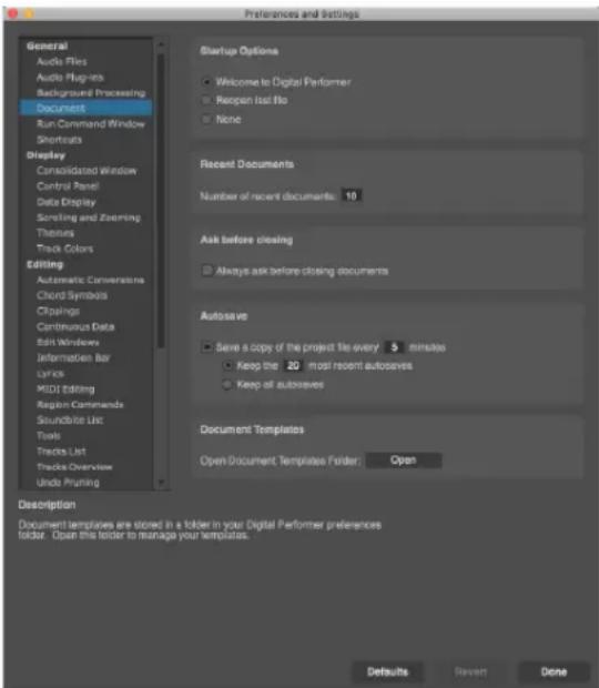
Figure 7-1: Preferences window
Restoring factory default settings
To restore factory default settings for the current preferences being displayed in the window (as indicated by what is currently selected in the list), click the Defaults button.
Reverting
If you have made changes to the current preferences being displayed in the window (as indicated by what is currently selected in the list), and you change your mind and wish to go back to the settings as they were before you made changes, click the Revert button.
Closing the Preferences window
Changes you make in the Preferences and Settings window go into effect as soon as you make them. To close the window, click its close button, or click the Done button.
AUDIO FILES
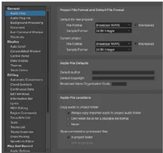
Figure 7-2: The Audio Files preferences
Project File Format and Default File Format
Digital Performer supports a variety of audio formats:
■ File Formats: AIFF, Broadcast WAVE
■ Sample Formats: 16-bit integer, 24-bit integer, 32-bit floating point
■ Interleaved Formats: interleaved and deinterleaved
Here you can specify the default settings for new projects and the settings for the current project. These settings affect newly recorded or created files; they do not affect existing files in your project.
Wave64
If you anticipate creating audio files larger than 4 GB, choose the Broadcast WAVE file format. How quickly you create a 4 GB file depends on the channelization, sample rate, and sample format. When recording a mono 16 bit 44.1 kHz file, it takes about 13.4 hours to create a 4 GB file, but less than an hour when recording an interleaved stereo 24 bit 192 kHz file.
When using Broadcast WAVE, if a file will be smaller than 4 GB at the end of an audio recording pass, the resulting file will be a regular Broadcast WAVE file. If the resulting file will be larger than 4 GB, it will use the industry standard Wave64 extension to the Broadcast WAVE file format.
Audio file defaults
Default Author / Default Copyright determine the default text for these items in new audio files. These fields are saved in the audio files and can be view in the Sound File Information window.
Broadcast Wave Organization Code is the three-character organization code that Digital Performer includes in the Unique Source Identifier field of all Broadcast WAVE format files. Refer to EBU document I30-1997 or www.ebu.ch for more information.
Audio File Locations
Digital Performer provides several global preferences (that apply across all projects) for choosing where imported or converted audio is stored on disk.
Copy Audio to Project Folder options
These options control where imported audio files are stored, including audio files that do not need to be converted into Digital Performer's native file format.
Digital Performer supports a variety of native audio file formats: mono, stereo, or multi-channel AIFF, and Broadcast WAVE files, interleaved or deinterleaved, in 16-bit integer, 24-bit integer, or 32-bit floating point formats. If you import audio that is already in one of these formats, it does not
need to be converted. However, you may find it to be convenient for Digital Performer to automatically copy the imported file into the project's Audio Files folder anyway, so that all audio for the project, imported and otherwise, is consolidated in one place. If so, choose the Always copy Imported Audio To Project Folder option. If you only want this to happen when the imported audio is in non-native format and needs to be converted, choose the Only when format is not a playable file format option. If, however, you want even converted files to remain in the same folder as their originals (instead of the project's Audio Files folder), choose the Never option.
Store converted or processed files options These options control where converted or processed files are stored. The In Project folder option refers to the Audio Files folder in the project folder. This option ensures that the audio files are always consolidated together in the project folder. The With Original File option stores converted files in the same folder as the original file.
AUDIO PLUG-INS
This preference pane allows you to manage your audio plug-ins. For details, see “Audio plug-in preferences” on page 901.
BACKGROUND PROCESSING
For details about the background processing preferences, see “Background processing preferences” on page 928.
DOCUMENT
Startup Options
Choose how you would like Digital Performer to open when you first launch the application. Digital Performer can do one of three things:
■ Open the Welcome to Digital Performer window
■ Open the project you last had open
- Neither of the above. In this case, no window or dialog box appears. Instead, Digital Performer's menu bar appears at the top of the screen, and the only menu available is the File menu, from which you can choose New or Open.

Figure 7-3: Document preferences
Recent Documents
Specify the number of recent documents that you want to appear under File menu > Open Recent.
Ask before closing
When the Ask before closing preference is enabled, Digital Performer always asks before closing the project. This is useful in situations where re-opening projects might take a long time due to virtual instrument loading.
Autosave
Autosave can be toggled on or off, and the save interval can be specified (from 1 to 60 minutes). You can keep all Autosave files or limit to a certain number of the most recent ones. Autosaved files go in an Autosave sub-folder in the project folder.
Document Templates
This “Open” button will open the folder on disk which contains your Document Template files. There, you can rename, copy, delete, etc. your template files.
RUN COMMAND WINDOW
By default, the Run Command Window is assigned to shift-spacebar. You can, of course, reassign it to any key combination you wish in the Commands window (“Commands” on page 105). The Run Command Window preferences (Figure 7-4) provide several choices.

Figure 7-4: The Run Command Window preferences
Top Hit Results
Top Hits are the most recently used commands that match the text string you've entered in the Run Command window. Type in the number of top hits you wish to see in the Maximum number of Top Hits to Show box, or uncheck the Show Top Hits box to hide all top hits. Click Clear to clear (reset) all current top hits.
Other results
The Other Results options (Figure 7-4) let you show/hide command groups and disabled commands in the Run Command window results list (Figure 9-5 on page 107).
SHORTCUTS
The Shortcuts window (Studio menu) provides convenient shortcut buttons for commonly used windows and dialogs.
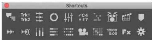
Figure 7-5: The Shortcuts window
The size and shape of the window can be changed by dragging the resize thumb in the lower right corner; the buttons will automatically reconfigure themselves to match the new layout.

Figure 7-6: The Shortcuts window can be resized to different layouts.
To configure which buttons you would like to appear in the Shortcuts window, use the Shortcuts preference pane.
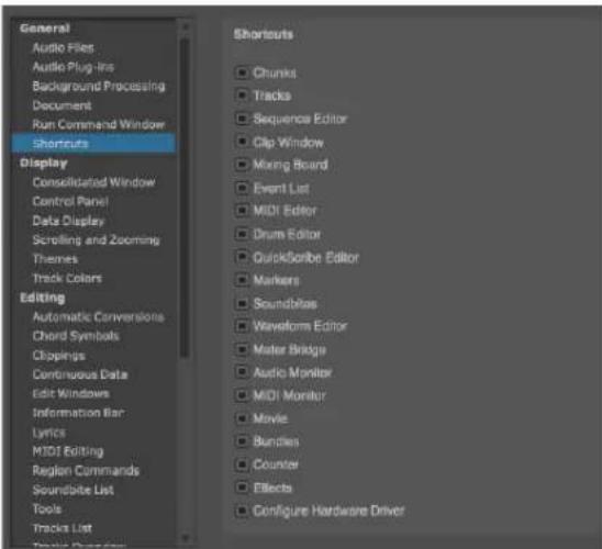
Figure 7-7: The Shortcuts window preferences
As you hover the cursor over each item in the list, a description appears below along with a picture of what its button looks like.
All major windows have a shortcut button available, with these two exceptions:
■ To open the Configure Studio Settings dialog, Option/Alt-click the Configure Hardware Driver button.
■ To open the Notation Editor, Option/Alt-click the QuickScribe Editor button.
CONSOLIDATED WINDOW
For details about the Consolidated Window preferences, see “Consolidated Window preferences” on page 112.
CONTROL PANEL
The Control Panel has options to float as a separate window (with adjustable transparency) or to appear across the top of the Consolidated Window. There are many options for what to show and hide in the Control Panel. These settings are controlled in the Control Panel preferences pane. Also see “Displaying the full tool palette” on page 218.

Figure 7-8: The Control Panel Preferences
DATA DISPLAY
The Data Display Preferences give you several choices for how to display information.

Figure 7-9: The Data Display Preferences
Pitch Display
The Pitch Display preference lets you choose how note octaves are numbered. Also lets you control how pitches are displayed. Your choices are by note spelling/octave (C3) or by MIDI note number (60).
Tempo Display
Digital Performer can display tempos throughout the program in beats per minute or in clicks per frame (i.e. "frame clicks"). Frame click tempos can be displayed with either a slash (/) or a dash (-).
Frame-clicks have their origin in the days of film before computers where a click track was created by physically punching holes in the film. As the hole passed over the projector's sound head, a pop or click was heard. The interval between the holes would determine how fast the click track would be.
Frame-clicks are expressed in two numbers. The first represents the number of whole frames between punches. The second represents fractions
of a frame; as there are four sprocket holes in a frame of film, a punch could be made at each of the holes or the space between them, making eight total sub-frame placements. So for example, 12-0 means that a punch would be made every 12 frames; since film runs at 24 frames per second, this equals two clicks per second, or 120 beats per minute. If you wanted the tempo to be a bit slower, you could punch holes at every 12 frames plus a sprocket or the space in between: 12-1, 12-2, etc.
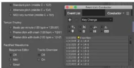
Figure 7-10: Set the Temp Display preferences as desired to determine how tempos are displayed throughout Digital Performer.
Regardless of how the tempos are displayed, you can type them in using either format and Digital Performer will convert between the formats at an extremely high degree of resolution (well beyond a hundredth of a bpm).
Rectified waveform display
Rectified waveforms provide twice the detail in the same vertical space as regular waveforms. They are especially useful when the vertical size of an audio track is very small.

Figure 7-11: Rectified waveforms in the Track Overview.
As shown in Figure 7-9, rectified waveforms can be enabled or disabled separately for the Sequence Editor, Track Overview and POLAR window to suit your tastes. In the Sequence Editor, the choices are Off, Mini, Small, Medium and Always. The Mini, Small and Medium choices refer to the vertical size of a track that causes it display rectified waveforms. For example, if you prefer to see normal waveforms most of the time, but prefer to see rectified waveforms only for fairly small vertical track sizes, choose Mini or Small. Rectified waveform display is temporarily suspended when you zoom into the sample level.

Figure 7-12: In this example, the 'Electric Guitar 1' track is rectified because it is vertically smaller than the other tracks.
Audio pitch automation reference
The Audio pitch automation setting lets you adjust the reference frequency for audio pitch automation. This preference defines the A above middle C, with a default setting of 440 Hz.
SCROLLING AND ZOOMING

Figure 7-13: The Scrolling and Zooming Preferences
Scrolling and Zooming Sensitivity
Use the Scroll Scaler slider to adjust the speed of scrolling and zooming. A value of 1 represents normal speed. Move the slider to the left (lower values) to slow things down; move it to the right (higher values) to speed things up.
Scrolling with Trackpad
Check this option to prohibit diagonal scrolling and constrain trackpad scrolling vertically and horizontally. When unchecked, you can freely scroll vertically, horizontally and diagonally. In either case, hold down the Ctrl/Win key to temporarily toggle the current preference setting.
Auto Scroll
For details about the Auto Scroll settings, see "Auto scroll" on page 226.
MIDI Auto Zoom
These two preferences allow you to specify the default “Auto Zoom Track” setting (page 332) for both new MIDI tracks and/or existing MIDI tracks in the current project.
THEMES
Digital Performer's user interface can be changed with themes, configured in the Themes preference pane.

Figure 7-14: Themes preferences
A variety of themes are included. To change the theme, select a theme in the list and press the Choose button.
The DP Version column displays the compatible versions of Digital Performer for each theme. If a theme does not support the current version of Digital Performer, the theme will be unavailable (grayed out).
A text description and preview image of the selected theme is displayed in the bottom portion of the Preferences window.
Selection Color
Selection color can also be further customized.
Option
Where the color is defined
| Use Theme's Selection Color 'The theme |
| Use A Custom Selection Color The single color picker |
| Use the System Selection Color The Highlight Color setting in System Preferences > Appearance |
Examples are shown for each selection color option.
Focus Color
The Focus Color refers to the highlighted border that appears around the focused cell in the Consolidated window. (See “Cell focus” on page 116.) Each theme has a default color for this highlight border, or you can customize the color.
Meter Color
Meter color can be further customized.
Option
Where the color is defined
| Use Theme’s Meter Color The theme | |
| Use A Custom Color The single color picker | |
| Use A Custom Color Gradient | The three color pickers, for the bottom, middle, and peak ranges, respectively |
Animated examples are shown for each of the meter color options.
Clip Color
Clip color can be further customized.
Option
Where the color is defined
| Use Theme's Clip Color The theme |
| Use A Custom Clip Color The color picker |
| Use the Track Color The track color |
Managing theme files
Themes are installed in the following location:
Platform
Path
| macOS /Library/Application Support/MOT'U/Digital Performer/Themes/ |
| Windows C:\ProgramData\MOTU\Digital Performer\Themes\ |
Press the Open button (Figure 7-14 on page 83) to open the folder on disk which contains your theme files. There, you can rename, copy, delete, etc. your theme files.
TRACK COLORS
Digital Performer allows you to choose any display color you want for each track. Coloring tracks can help you to distinguish them more easily in the Track Overview, Mixing Board, MIDI Editor windows and elsewhere in the program. You can use preset colors or choose any color you want from the color picker. Digital Performer also provides many different color schemes (sets of colors) for you to choose from. You can even create your own schemes.
The Track Color Preferences
Choose View menu > Color > Track Color Preferences to set the color use preferences:

Figure 7-15: The Track Colors preferences.
The check boxes in the Track Colors section let you enable/disable the use of color in various windows.
Use custom track colors
In the Use custom track colors section, use the check boxes to choose the various windows in which you would like to display customized track colors.
Assign new tracks options
The Assign new tracks options let you determine how color is assigned to new tracks when they are first created.
To all different colors: when a new track is created, this option gives it a color from the current color palette.
To different shades of the same color: when a new track is created, this option gives it a shade of the color you choose from the swatch menu at the bottom of the Track Color Preferences dialog.
To the same color: when a new track is created, this option gives it the exact same color you choose from the swatch menu at the bottom of the Track Color Preferences dialog.
Use different colors for different track types:
when a new track is created, it is given the color you specify with the swatches below, according to what type of track it is.
Edit Color Schemes
This "Open" button provides quick access to the Edit Color Schemes dialog (View menu > Colors).
Use Soundbite Color Bar
When the Use Soundbite Color Bar option is checked, a color bar is displayed across the top of each soundbite in the Sequence Editor, as shown below, and in the Track Overview (Figure 20-1 on page 173). The color matches the current track color you've chosen (Figure 7-20 on page 88).

Waveform Colors
The Waveform Colors sliders let you determine how colors are displayed for soundbite waveforms. Both the waveform itself, and the background within the soundbite, have independent saturation and lightness controls, giving you a great deal of control over the appearance of waveforms. These controls allow you to optimize waveform appearance for your preferred Theme and track color scheme. A few examples are shown below:

Where track color gets displayed
The color for a track is displayed in several places throughout the program:
■ On the color swatch in the Track List
■ On soundbites and MIDI data blocks in the Track Overview
■ On soundbites in the Sequence Editor (according to the Waveform Colors preference, see above)
■ On MIDI notes in the MIDI Editors
■ On Tracks in the Mixing Board
■ On audio crossfades (and fades)

Figure 7-16: A crossfade is displayed with the audio track's color.
Working with color schemes
A color scheme is a set of related colors that can be easily interchanged with a different set of related colors. For example, you could have a "Metallic"
scheme and a “Earthy Pastels” scheme. Digital Performer provides several preset schemes, and you can freely change between them at any time. You can also create your own schemes.
Changing the color scheme
To switch to a different color scheme, go to the View menu, choose Colors and choose the desired scheme from the sub-menu.
Editing color schemes
To edit a color scheme, go to the View menu, choose Colors > Edit Track Color Schemes. Doing so opens the Edit Track Color Schemes dialog as shown below in Figure 7-17. The scheme currently being used is highlighted.

Figure 7-17: The Color Schemes dialog.
To do this Do this
| To choose a different scheme Click it once to select it and then click Done. |
| To edit a scheme Double-click it. Or click it once to highlight it and click the Edit button. |
| To delete a scheme Click it once to highlight it and click the Delete button. |
| To rename a scheme Click it once to highlight it and click the Rename button. |
| To duplicate a scheme Click it once to highlight it and click the Duplicate button. |
| To make a new color scheme Duplicate an existing one (as described above), rename it, and edit it as desired. |
To make a new color scheme Duplicate an existing one (as described above), rename it, and edit it as desired.
Modifying a color scheme
To modify a color scheme, double-click it in the Edit Track Color Schemes dialog (shown in Figure 7-17). When you do, the color palette appears as shown below in Figure 7-18.

Figure 7-18: A color scheme palette. The 12 swatches in the left-most and right-most columns — the ones with the heavier borders — can be changed. The swatches in-between are automatically filled with a gradual blend of the colors on either end of the row.
Here is a summary of what you can do in this window:
To do this Do this
| To open the color picker Double-click on any swatch in the left-most or right-most columns. | |
| To fill a swatch using the eyedropper tool | Click once on the swatch to select it and then move the cursor over any color on your screen — even colors outside of Digital Performer and its windows. |
| To move a row up or down Drag the swatch on either end of the row. | |
| 'To flip a row (switch the left- and drag either swatch to the other right-most swatches) side of the row. | |
| 'To change which swatch is currently selected (with a heavy border) Use the arrow keys, or click the desired swatch. | |
Using the Color Picker
The color palette (as shown in Figure 7-18 on page 87) also lets you create your own colors using the macOS or Windows Color Picker. To open the color picker for a swatch, just double-click the swatch. Remember, only the swatches in the left-most and right-most columns of the palette can be modified. The swatches in the middle of each row are automatically filled with a gradual blend between the colors on either end of the row.

natural_image
Color picker interface with a gradient circle and color swatch, no text or symbols on the color itself
Figure 7-19: Double-click any swatch with a heavy border to open the standard macOS or Windows color picker. Use the eye-dropper tool (circled) to choose any color on your screen.
Using the color picker to "import" colors (Mac only)
The color picker (as shown in Figure 7-19 above) lets you import any color you like using the magnifying glass tool. Just click the magnifying glass, and then move the cursor anywhere on your computer screen — even windows, dialogs, icons, and other items outside of Digital Performer (on the macOS desktop or in other applications running at the same time as Digital Performer).
For example, you could open a graphic image of some kind in Adobe Photoshop (or other graphics program) and then use the magnifying glass tool to import any color that is currently visible in the graphic image on your screen. You might find it helpful in this situation to close all of Digital Performer's other windows before opening the color picker so that they will not cover up parts of the image you would like to click with the magnifying glass tool. You could also make a window set that consists of all windows being closed (except the Control Panel, of course).
Choosing a track's color
To choose a color for a track, click on the color swatch next to the track name in the Tracks Window, as shown below in Figure 7-20. Or Control/Win-click the track name in the Sequence Editor, Mixing Board or V-Rack.

Figure 7-20: Choosing a color for the 'Vocals' track.
Assigning colors
The Assign Track Colors sub-menu command (View menu) lets you Assign Track Colors to multiple tracks at one time. Numerous options are provided, as shown below in Figure 7-21:

Figure 7-21: Assigning colors to many tracks at one time.
To use the Assign Track Colors command, select one or more tracks and then choose View menu > Colors > Assign Track Colors. Choose the option as desired and the click OK. Below is a summary of the assign color options:
Option Explanation
| according to Track Color Preferences | Assigns colors to each track according to the settings in the Track Color Preferences dialog (Figure 7-15). |
| to all different colors | Assigns a color to each track from the currently selected color scheme (palette). When the “Pick Colors Randomly” check box is not checked, this option starts at the beginning of the palette and works its way towards the end as needed according to the number of tracks selected. If “Pick Colors Randomly” is checked, it will assign colors randomly from the palette. |
| to different shades of the same color | Lets you choose a specific color from the color palette and then only uses the various shades of that color (from the same row in the palette). |
| to colors in a range | Lets you choose a start color and an end color from the color palette and then cycles through all the colors in between as needed according to the number of tracks selected. |
| to the same color | Lets you assign all currently selected tracks to a single color of your choice (as specified by the swatch provided). |
to the same color Lets you assign all currently selected tracks to a single color of your choice (as specified by the swatch provided).
The 'Pick Colors Randomly' option
The Pick colors randomly option appears for several of the choices above it in the Assign Track Colors dialog. When it is checked, it assigns the specified colors at random to all currently selected tracks. When it is unchecked, colors are assigned from the current color scheme palette starting with the first color specified and then proceeding to the right and then down to the beginning of the next row.
AUTOMATIC CONVERSIONS
Digital Performer can automatically convert audio data wherever necessary to make it conform to the current project's sample rate, file format, interleaved format, and tempo. Because processing is initiated automatically and carried out via background processing (for lengthy operations), these auto-conversion features greatly streamline the process of importing audio quickly into your projects, or the process of converting the entire project to a different sample rate, file format, interleaved format, or tempo.
The Automatic Conversions preferences (Figure 7-22) provides a global switch (the Enable Automatic Conversions option), and it also allows you to further specify your preferences for how audio is automatically converted.
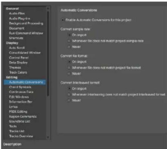
Figure 7-22: The automatic audio file conversion preferences.
Enabling and disabling automatic conversions
Use the Enable Automatic Conversions check box to turn automatic conversions on or off for the current project. This setting is saved with the project. You can also toggle this setting with a key binding.
Automatic conversion settings
The following settings let you customize how files are automatically converted. Settings are provided to handle sample rate, file format, interleaved format, and tempo.
On Import
This option, along with the When Bite is Added to A Track option, converts audio when it is first imported into Digital Performer, and in the case of tempo, when it is first placed in a track.
Whenever File Doesn't Match Project
These options do the same thing as the On Import option, plus they automatically convert audio whenever circumstances arise where the audio no longer matches the project. For example, if you change the tempo for the sequence, all audio that is affected by the new tempo will automatically be time-stretched to match the new tempo. Or if you decide to change the project's sample rate, say from 48kHz to 44.1kHz, all audio will
automatically be sample rate converted. Needless to say, you need to be mindful of making changes like this, as very large amounts of audio data can be generated as a result of using these options.
Never
Choose this option when you don't want audio files to be automatically converted for this file characteristic.
Setting auto conversion options on a per file basis
You can choose audio conversion settings for individual audio files that override the current settings in the Automatic Conversions preferences (Figure 7-22). To do so, click the audio file by name in the Soundbites list, or a soundbite that belongs to it, and choose Studio menu >Sound File Information. In the Sound File Information window, check or uncheck the items in the Automatic Conversions section as shown below in Figure 7-23.

Figure 7-23: In the Automatic Conversions section, check items to enable them. These settings override the settings in the Automatic Conversions preferences.
CHORD SYMBOLS
For details about the Chord Symbols settings, see "Chord symbols preferences" on page 499.
CLIPPINGS
For details about the Clippings preference (Figure 7-24), see “Signal routing within a multi-track clipping” on page 708.

Figure 7-24: The Clippings preference.
CONTINUOUS DATA
the Continuous Data preferences are shown in Figure 39-13 on page 425.
For details about Set Ramp Density, see "Ramp density" on page 430.
The Switches are Continuous Data check box, when checked, causes all controllers, including switch controllers #64 and above, to be displayed and edited as continuous controllers in the continuous data grid of the MIDI Editor and Sequence Editor. This is useful for MIDI devices, such as MIDI-controlled lighting consoles, that use all MIDI controllers as continuous controllers. For details, see “The Continuous Data Grid” on page 422.
For details about the Continuous Data Icons, see "Cont. Data Icons" on page 425.
For information about the On Velocities preference, see "On-velocity tails" on page 426.
EDIT WINDOWS
Fix partial measures automatically
A partial measure is a measure that does not have a complete set of beats in it as determined by the current meter. Partial measures can be created in Digital Performer by inserting a Meter Change event in the middle of a measure. Since meter change events always start a new measure, a meter change event truncates any measure if it is inserted in the middle of the measure. This is a powerful feature of Digital Performer, especially handy when scoring music to picture because you can start a new measure at any SMPTE frame.
If the Fix partial measures automatically is turned on (checked), and you open a Digital Performer project that has partial measures, it will automatically get rid of the partial measures by moving meter changes as needed to do so. After the file opens, you should check to see if your MIDI data still lines up with all the barlines the way you want, and make adjustments with the Change Meter and/or Shift features as desired. If you want to get rid of partial measures in your files, leave this option turned on. If you want to preserve partial measures in a file, uncheck this option before opening the file. Don't worry, however: Digital Performer presents an alert before it corrects partial measures so that you can Revert to Saved if you decide not to do so.
Track Selector button
This preference determines the behavior of the track selector button found in each edit window. For details, see “Track Selector button preferences” on page 364.
Edit Window guides
The Show marker grid lines and Show edit grid lines options toggle (show or hide) the display of lines extending downwards from the MIDI Editor and Sequence Editor time rulers through the note grid and continuous data grid from markers in the marker strip or beats in the time ruler (for the Edit Grid).
The Show beat grid lines shows or hides beat grid lines within soundbites that have been beat-analyzed with the Beat Detection Engine. For details, see chapter 53, “Audio Beats and Tempo Detection” (page 681).
The Show tempo mismatch lines shows or hides red lines within soundbites when the soundbite tempo doesn't match the sequence tempo. For details, see chapter 52, "Tempos and Audio" (page 673).
Default Edit Windows
This setting determines what edit window opens (Event List, MIDI Editor, Notation Editor, Drum Editor, QuickScribe Editor or Sequence Editor) when you double-click a track. In addition to double-clicking a track, there are many modifier key shortcuts for opening all other edit windows. For a complete list, see “Opening an edit window for a track” on page 181.
INFORMATION BAR
This preference pane is used to configure how the Information Bar will appear in each edit window. For more information, see “Information Bar” on page 367.
LYRICS
For details about the Lyrics settings, see “Lyrics preferences” on page 509.
MIDI EDITING
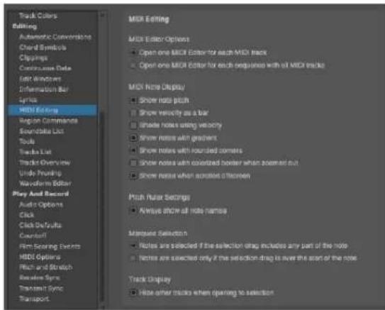
Figure 7-25: The MIDI Editing preferences.
MIDI Editor options
These two preferences control the MIDI Editor. If you would like a separate editor window for each MIDI track (that displays data only for that one track), choose Open one editor for each track. If you would like one global MIDI Editor window that can display one or more MIDI tracks in one window (with collapsible track selector list on the left side of the window), then choose Open one MIDI Editor for each sequence.
MIDI Note Display preferences
Show note pitch: When checked, MIDI notes display their MIDI note number inside the note bar itself, at the left edge of the note, as shown in Figure 39-6 on page 418. MIDI note numbers appear when the note grid is vertically zoomed in far enough to display text inside the note.
Show velocity as bar: When checked, MIDI notes display their note-on velocity as a bar inside the note, similar to a thermometer, as shown in Figure 39-6 on page 418. The higher the velocity, the longer the bar (from left to right). Shade Notes using Velocity: When checked, MIDI notes will be shaded according to their on-velocity. The higher the velocity, the darker the note. Conversely, the lower the velocity, the lighter the note.
Show notes with gradient: When checked, MIDI notes are displayed with gradient shading to give them a more 3D appearance.
Show notes with rounded corners: When checked, MIDI notes are displayed with rounded corners.
Show notes with colorized borders when zoomed out: When enabled, this option can improved the visual clarity of notes when the note grid is zoomed out.
Show Notes When Scrolling Offscreen: When this item is checked, the note grid displays a small bar at the top border or bottom border when a note resides above or below the pitch range currently being displayed. See “Viewing notes that are out of view” on page 418.
Pitch Ruler Settings
When checked, the Always show all note names option causes every key on the MIDI edit grid pitch ruler to display its respective MIDI note name. When the pitch ruler gets zoomed out (and the keys get narrow), note names will only appear on white keys. When this preference is disabled, note names only appear on octaves (c3, c4, etc.)
Marquee Selection
The Marquee Selection preference lets you control whether notes are selected if either a) the start of the note is within the marquee selection or b) any portion of the note is within the marquee selection. See “Selecting a group of notes” on page 420.
Track Display
Hide Other Tracks When Opening to
Selection: When checked, this option allows you to open (or refresh) the MIDI Editor or the Drum Editor in the Consolidated Window with only the currently selected tracks showing in the window. This option also applies to opening the MIDI Editor when the Open one MIDI Editor for each sequence with all MIDI tracks option is chosen. The Drum Editor always follows this preference setting.
REGION COMMANDS
For details about the Region Command preferences, see “Region command preferences” on page 594.
SOUNDBITE LIST
For details about the Soundbite list column setup preferences, see “Showing/hiding columns in the soundbite list” on page 43.
TOOLS
Cursor Selection Mode
The Cursor Selection Mode menu provides several choices for selection operations in graphic editor windows. For complete details, see “Choosing a Pointer tool selection mode” on page 548.
Tool Palette Options
The Tool Palette Options allow you to automatically dock the Tool palette to the edge of edit windows, either vertically or horizontally.
Vertical Tool palette
This check box option, when enabled, causes the Tool palette to assume a vertical orientation.
Auto Position Tool Palette
This check box option, when enabled, allows you to "dock" the tool palette to the outside edge of the front-most edit window. Just drag the Tool Palette near the desired edge of the front most edit window, and it will snap to the outside edge, justified to the nearest corner. Press Shift-
Option-tilde (\~) to toggle the Tool palette between a vertical or horizontal orientation. When it is vertical, it will snap to the left or right edge of the front-most edit window. When it is horizontal, it will snap to the top or bottom edge.
When the Tool palette is docked, it will automatically dock itself to the front-most edit window, regardless of which window is in front. If the docking position is off-screen when you first bring the window to the front, the palette will automatically jump to the opposite edge, if currently visible.
If you resize the edit window with the zoom button in its title bar, it will automatically leave room for the docked Tool palette.

Figure 7-26: The Tool palette docked to the lower right corner of edit windows. The palette automatically docks itself to the front-most edit window.
Show in Tool Palette
Check the box next to the tools you would like to see in the Tool palette.
TRACKS LIST
For details about the Tracks List preferences, see "Showing and hiding columns in the Track List" on page 176.
TRACKS OVERVIEW

Figure 7-27: Tracks Overview preferences.
Playback and Scrub Wiper
When the Snap the wiper to the edit grid preference is enabled, the playback wiper snaps to the column grid in the Tracks Overview when you drag it. If you would like to be able to drag smoothly, with no snapping, disable this option. Either way, you can override the current setting by holding down the command/Win key while dragging the wiper.
MIDI Level Meters
For details about the Track List MIDI level meter preferences, see “Configuring the MIDI activity meters” on page 177.
Phrase Settings
For details about the Tracks Overview phrase setting preferences, see “Customizing MIDI phrasing blocks” on page 182.
UNDO PRUNING
For details about the Undo Pruning preferences, see “Pruning preferences” on page 578.
WAVEFORM EDITOR
For details about the Waveform Editor preferences, see “Waveform Editor preferences” on page 544.
AUDIO OPTIONS
The audio options apply to Digital Performer's audio recording features.
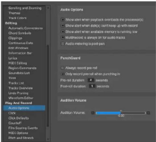
Figure 7-28: The Audio Options preferences.
Show alert when playback overloads the processor(s)
When this preference option is checked, Digital Performer will display an alert dialog when system resources do not allow it to play back audio without interruption. In other words, if the clip light in the Audio Performance Monitor lights up, this option will also cause an alert dialog to appear. This option is useful for circumstances where you want to be sure that playback is completely uninterrupted, such as if you are transferring a final mix to a DAT tape. To alleviate processor load, bounce effects to disk and quit other applications, which can add additional strain to your computer's resources.
Show alert when disk(s) can't keep up with record
When this preference option is checked, Digital Performer will display an alert dialog when system resources do not allow it to record audio without interruption.
Show alert when available memory is running low
When this preference option is checked, Digital Performer will display an alert dialog when your computer's system memory reserved for applications like Digital Performer is running low.
MultiRecord is always on for audio tracks
Causes audio tracks to always be in this mode.
Audio metering is post-pan
Check this option if you would like audio meters (in the Mixing Board, Meter Bridge, etc.) to display channel levels after the panner has been applied to the channel's signal.
Punch Guard
When Always record pre-roll is chosen, Digital Performer always records extra time before any record pass, as specified by the pre-roll duration option provided. When Only record pre-roll when punching in is enabled, pre-roll is only recorded when either manually or automatically punching in on the fly. This is the default behavior. For details, see “Punch Guard” on page 248.
Audition volume
The Audition volume fader (Figure 7-28 on page 94) allows you to control playback volume of Digital Performer's various auditioning features, including Audible mode, the various auditioning commands (in the Commands window), selecting a soundbite in the Soundbites list, scrubbing or edge-editing a soundbite and previewing effects applied as a Region operation.
CLICK
For details about the click preferences, see "Click Preferences" on page 256.
CLICK DEFAULTS
For details about the click default options, see "Click Defaults" on page 258.
COUNTOFF
For details about the countoff options, see "Countoff preferences" on page 259.
FILM SCORING EVENTS
For details about Film Scoring Event settings, see chapter 66, “Streamers, Punches and Flutters” (page 787).
MIDI OPTIONS
For details about the MIDI Patch Thru preferences, see “MIDI input monitoring” on page 238.
For details about the MIDI Solo Setup settings, see “Partial-solo” on page 223.
For details about the MIDI Recording option (Record MIDI in Tracks as Clips), see Step 8 in "Preparing a MIDI track for recording" on page 235.
PITCH AND STRETCH
The Pitch and Time Stretch Options (Figure 7-29) provide several settings that affect the CPU load and processing time of audio time-stretching and pitch-shifting throughout Digital Performer.

Figure 7-29: Transport preferences.
The Stretch and Pitch and Stretch Cache options let you choose whether these features are enabled for tracks that you add in new projects and the current project. For information about these features, see “Stretch” on page 149 and “Pitch and Stretch Cache” on page 150.
The ZTX-related settings also have an effect on the nature and quality of pitch-shifting processing, from pencil tool edits in the Sequence Editor pitch layer to wholesale transposition using the Transpose command. For details on these settings, see “ZTX Preferences” on page 924.
RECEIVE SYNC
For details about the Receive Sync settings, see "Using Receive Sync" on page 978.
TRANSMIT SYNC
For details about the Transmit Sync settings, see chapter 88, "Transmit Sync" (page 1001).
TRANSPORT
The Transport preference controls the behavior of the Wait button and the Fast Forward/Rewind buttons.

Figure 7-30: Transport preferences.
Wait button
When a note is played
If the When a note is played option is chosen, the main transport will start moving when a MIDI note-on is received.
When a note or controller is played
If this option is chosen, the transport will start when a MIDI note-on or MIDI controller event is received.
On any MIDI activity
If this option is chosen, the transport will start moving when any MIDI data is received, except for active sensing or MIDI clock.
Fast Forward/Rewind buttons
Move playback position by...
Choose this option to move the playback position by a fixed increment in one of the following formats, chosen from the menu: measures, beats, ticks, frames or seconds. You can then specify different increments for slow versus fast cueing.
Move playback position continuously
Choose this option to move the playback position smoothly, like an old tape recorder.
SCALING ALL WINDOWS UP OR DOWN
Digital Performer gives you the ability to scale the appearance of all windows and text larger or smaller. To do so, choose View menu > Scale > Scale All Windows Up/Down.
HELP MENU
Digital Performer Help viewer
The Digital Performer Help viewer provides quick answers to some questions. See “Help Viewer” on page 193 in the DP4 Getting Started Guide.
Help Tags
There is a Show Help Tags checkable item under the Help menu. When checked, you can hover over most items for a second or two and a “tooltip” description of the item will appear.
→

Checking for updates
Digital Performer can automatically check for new versions. When a new version is available, a dialog will prompt you with options to download or skip the update.

Figure 7-31: Automatic update check.
This automatic check can be disabled by deselecting Help menu > Check for Updates Automatically. To check for updates manually, choose Help menu > Check for Updates Now.
Additional Help menu resources
The help menu also provides additional resources, including a direct links to PDF files for the Digital Performer User Guide, Getting Started Guide, Plug-in Guide, and additional PDF documentation files. There are also menu items that provide direct web links for on-line product registration, technical support, and downloads.
CHAPTER 8 Time Formats and Display
OVERVIEW
Digital Performer can display cursor and event information in a variety of formats, configured with the Time Formats window (Setup menu).
To configure the time formats for the Control Panel counters, see “Setting the counter time format” on page 202.
Specification of time formats 99
Time Formats window....100
SPECIFICATION OF TIME FORMATS
In Digital Performer, you will always be dealing with time specifications. Digital Performer gives you the option of using measure time (measure|beat|tick), real time (minutes:seconds.hundredths), frame time (hours:minutes:seconds:frames) and samples (digital audio samples).
Measure time (measure|beat|tick)
1|1|000
Figure 8-1: Specifying time in measures, beats, and ticks.
Measure time is the most musical of the time formats. Locations are displayed in standard measures and beats, with an additional unit called the tick. The three units are separated by vertical bars. The example shown above shows measure 1, beat 1, tick 0.
The number of beats in the measure depends on the specified meter: 4/4 will define 4 beats per measure, for example. Subdivisions of the beat vary, according to the ticks-per-quarter note setting you've chosen in the Time Formats window. The default tick value is 480 ticks per quarter note. At that resolution, a beat in 6/8 time (an eighth note) will have 240 tick subdivisions, a beat in 2/2 time (a half note) will have 960 tick subdivisions, and so forth. MIDI event times can thus be viewed and edited with an accuracy of 1/480 of a quarter note at this setting.
Data display resolution can be customized to be anywhere from 96 parts per quarter (PPQ) up to 10,000 PPQ. Additionally, up to four decimal places of resolution can be added. For example, if you prefer working at 480 PPQ, but would enjoy additional editing resolution and timing accuracy, you can add a few decimal places to 480. Data display resolution can be set using the Time Display settings in the Time Formats window (Setup menu). For more information on variable PPQ, see “MIDI display resolution” on page 102.
Unless you are doing film or video work, it is probably the only time representation you will need (though you may want to use real time for an objective measurement of the length of your sequence).
Real time (hours:minutes:seconds.hundredths)
0:00:00.00
Figure 8-2: Specifying real time in hours, minutes, seconds, and hundredths.
Real time is clock time, i.e. time expressed in hours:minutes:seconds.hundredths of a second. Real time is useful to measure elapsed time for your sequence. By default, the sequence begins at time 0:00:00.00; this can be changed with the Set Chunk Start Time command described on page 203.
Frame time (hours:minutes:second:frames)

Figure 8-3: Specifying SMPTE time in hours, minutes, seconds and frames.
Frame time is a visual display of SMPTE (Society of Motion Picture and Television Engineers) time code. It is generally used in film and video work, but is also used for synchronization in audio production. Unlike measure time, frame time is used when absolute time location is necessary.
It is displayed similarly to real time, in hours, minutes, seconds, and frames. Frames are subdivisions of a second. The first frame number in a second is zero.
Digital Performer supports these frame formats: 23.976 frames per second (fps), 24 fps, 25 fps, 29.97 fps, 29.97 drop-frame, and 30 fps. Additionally, there are three “nonstandard” frame rates available.
Nonstandard frame rates
Three nonstandard frame rates are available: 30 drop, Legacy 29.97 drop, and Legacy 29.97 nondrop.
■ 30 drop: Use only when you must accommodate this frame rate. You'll nearly always want to use one of the more common frame rates, such as 29.97 drop or 30 non-drop.
■ Legacy 29.97 drop and Legacy 29.97 non-drop: Use these only with old projects which open assigned to these frame rates. For new projects, always use the standard 29.97 drop and 29.97 non-drop frame rates.
Use these frame rates only in the cases described above; otherwise, use one of the standard frame rates.
SMPTE is useful as a standardized location scheme when synchronizing to production devices such as a tape deck or video deck. When synchronizing to an external time code source, the counter will always display the same frame time that is being received from the external source. You may specify the SMPTE location at which the first measure of the sequence or song starts. with the Set Chunk Start Time command described on page 203.
See chapter 86, “Receive Sync” (page 977) for a more detailed explanation of syncing to external timecode.
Samples

Figure 8-4: Specifying time in samples.
The Samples time format displays the number of digital audio samples since the beginning of the project. Digital Performer places digital audio in audio tracks with sample-accurate precision. MIDI data is stored with even greater precision.
TIME FORMATS WINDOW
The Time Formats window (Setup menu) lets you specify the time format to be displayed throughout Digital Performer in event lists, time rulers, dialogs, windows and any place where time is displayed.

Figure 8-5: Time Formats window.
Customizing the time format display
Click the Details triangle to further customize which time formats are displayed in various areas of Digital Performer. You can specify certain time formats as needed.

Figure 8-6: Customizing the time format display.
As soon as you make any changes in the Details area, a new custom time display setup is added to the Custom menu. You can create as many custom setups as you like. Use the Edit Time Formats command in the Custom menu to rename, duplicate and delete custom time format setups.
Saving time format settings with the project
By default, time format settings are global: they control the display of any project that you open. However, there are several commands in the time Formats window mini-menu that allow you to apply time format settings to the current project.
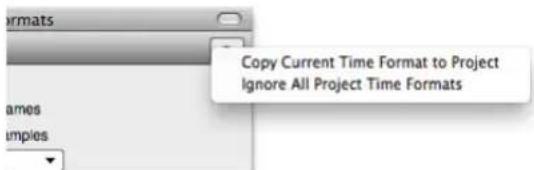
Figure 8-7: Use the Time Formats window mini-menu commands to apply time format settings to the current project.
The Copy Current Time Format to Project command saves the current Time Format settings with the current project. When you later reopen the project, these saved settings will be used instead of the current global Time Format settings.
The Ignore All Project Time Formats command is checkable. When enabled, it temporarily overrides saved time format settings, if any. For example, if you receive projects from colleagues that have project time format settings saved in them, you can temporarily override them and use your own global Time Format settings by checking this menu item. When this menu item is unchecked, the project always uses its saved time format settings, if any.
To use customized time format settings that you have copied to a project, select the Project option (below Custom in Figure 8-6). The other options (Measures, Frames, Real time, Samples and Custom) are global (not project specific).
Time format keyboard shortcuts
There are a several keyboard shortcuts for choosing the global time format. To locate them, search in the Commands window for one of their
names. The Next Time Format command cycles through all global time formats, including any custom formats you may have created and saved.
| Command | Default keyboard shortcut |
| Next Time Format Shift-period (.) | |
| Show Measure Time Command-Option-Control-MCtrl-Alt-Win-M | |
| Show Real-time Time Command-Option-Control-RCtrl-Alt-Win-R | |
| Show Frame Time Command-Option-Control-FCtrl-Alt-Win-F | |
Show Sample Time none
MIDI display resolution
When displaying the time of MIDI data, Digital Performer divides a quarter note into 480 ticks by default, giving the program 480 PPQ (parts per quarter note) timing resolution. A quarter note is 480 ticks long, an 8th note is 240 ticks, a 16th note is 120 ticks, and so forth.

Figure 8-8: The Time Display settings.
2 trillion PPQ
Digital Performer has a very high internal timing resolution. In fact, the internal timing resolution is about two trillion PPQ. In other words, the number that Digital Performer now uses to store the location of each MIDI event is a 64-bit number, which can express a range of numbers up to over 8,000,000,000,000,000,000. A quarter note can be divided into 2,000,000,000,000 parts, while still allowing a sequence over 4,000,000 quarter notes long.
Adjustable PPQ display
This very high degree of internal precision serves as the basis for Digital Performer's adjustable PPQ resolution. Digital Performer allows you to view and edit MIDI data at any PPQ resolution you want.
PPQ affects data display only
The adjustable PPQ resolution settings only affect how data is displayed in Digital Performer. They have no effect on how the data is recorded or played back. For example, data would be recorded just as accurately at 96 PPQ as it would at 9600 PPQ.
What PPQ should you use?
If you are a seasoned Digital Performer user, you are probably accustomed to working with 480 ticks per quarter note. Therefore, it might be easiest for you to continue using 480. You can add greater resolution to your editing, however, by simply adding extra decimal places from the decimal places menu (Figure 8-8 on page 102).

Figure 8-9: If you're a seasoned Digital Performer user, you can stick with 480 ticks per quarter note, and simply add decimal places to increase precision. In this example, three decimal places are being used, producing a thousand times the resolution of previous versions of Digital Performer.
If you're a Logic or Cubase user who has switched to Digital Performer, you could choose 960 or 1920, respectively. For even better PPQ resolution, add extra decimal places (e.g. 960.000 or 1920.000).
What's the minimum/maximum PPQ?
The minimum PPQ resolution you can choose is 2. The maximum PPQ resolution you can choose is 10,000.0000. At this maximum resolution, you can move a note by 0.0001 of a tick. In doing so, you've just nudged it by one one-hundred millionth of a quarter note.

Figure 8-10: With the above settings, one tick equals one one-hundred millionth of a quarter note.
PPQ chart
The following page shows a chart that displays the length in ticks of various note durations at several common PPQ resolutions.
SETTING THE START TIME
The start time serves as the base reference for all time readouts in Digital Performer. It is the time displayed in the counter when you rewind to the beginning. For details on setting the start time, see "Setting the start time" on page 203.
PPQ resolution:96 192 384 480 960 1920 3840
| whole | 384 768 1536 1920 3840 7680 15360 |
| half | 192 384 768 960 1920 3840 7680 |
| quarter | 96 192 384 480 960 1920 3840 |
| 8th | 48 96 192 240 480 960 1920 |
| 16th | 24 48 96 120 240 480 960 |
| 32nd | 12 24 48 60 120 240 480 |
| 64th | 6 12 24 30 60 120 240 |
| quarter triplet | 64 128 256 320 640 1280 2560 |
| 8th triplet | 32 64 128 160 320 640 1280 |
| 16th triplet | 16 32 64 80 160 320 640 |
| 32nd triplet | 8 16 32 40 80 160 320 |
| 64th triplet | 4 8 16 20 40 80 160 |
CHAPTER 9 Commands
OVERVIEW
The Commands window lets you assign keyboard shortcuts and/or MIDI events to Digital Performer functions. This allows you to use the wide variety of MIDI controllers as well as your computer's keyboard to quickly execute Digital Performer operations. For example, a MIDI note value of C0 could operate the Stop button in the Transport; controller 64 On could operate the Skip Forward button.
Opening the commands window....105
Navigating the commands window....105
Command groups....106
MIDI Masters ....106
Assignments ....106
Numeric Base note 107
Chunk remote assignment .....107
Run command....107
Export Key Bindings....108
Import Key Bindings....108
OPENING THE COMMANDS WINDOW
The Commands window is opened by choosing it from the Setup menu. The window contains a list of all assignable commands in Digital Performer. It is arranged in columns that display two keyboard assignments, a MIDI event assignment and master group designation.
NAVIGATING THE COMMANDS WINDOW
There are several ways to search and browse in the Commands window.
Searching for commands
Type in a text string at the top of the window. As you type a search term, the window will update in real-time to display the relevant results.
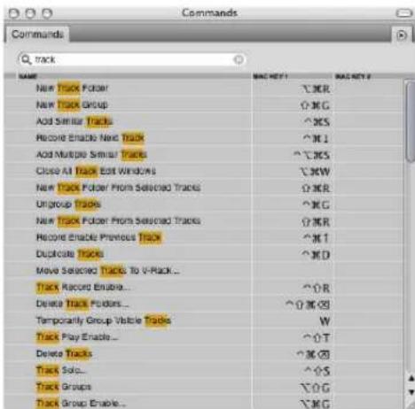
Figure 9-1: To search for a command, type in a text string and click Search.
To clear the search results and return to the regular view, click the "x" button at the right side of the search field, or press the Escape key.
Browsing with the list navigation commands
You can use the List Navigation Commands to navigate the Commands window, select any command and give it a key binding.

Figure 9-2: Use the List Navigation
COMMAND GROUPS
Commands are visually organized into logical groups. For example, all menu items found under the File menu are grouped together. Each group can be displayed or hidden by clicking the disclosure triangle to the left of the group name. Option/Alt-clicking a disclosure triangle will show or hide all groups.

MIDI MASTERS
The first group of commands are MIDI Master controls. MIDI Master controls enable or disable MIDI control of commands by group. Keyboard shortcut operation is unaffected. Like other commands, Masters can be assigned keyboard shortcuts or MIDI events.
Master controls have an additional check box next to their name that indicates their current status and allows you to manually enable or disable with the mouse.
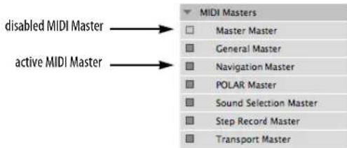
The ‘Master’ column in the Commands window indicates which master individual commands are controlled by.
The Master Master is a special master control that enables or disables all master controls, effectively enabling or disabling MIDI control of all commands.
The General Master governs all commands that are not covered by the other master commands (Navigation, POLAR, Sound Selection, etc.)
You can see which master a command is assigned to by widening the Commands window to view the master assignment column, as shown below:

Figure 9-3: Viewing the master assignment for each command.
ASSIGNMENTS
To assign a key binding to a given Command, simply click in the 'Key' column of a command and a field will appear indicating it is ready to receive a key stroke from the keyboard. The key or combination of key and modifiers you press at this time will be entered into the field.
There are two key bindings available for any given command. For example, the Slave to External Sync command could be mapped to both Command/Ctrl-7 and Option/Alt-s.
You can use any key you want, except for the delete key, which removes the current key binding, if any.
For your convenience, keyboard shortcut key assignments are displayed in Digital Performer's menus.
MIDI Assignments
Any MIDI event can be mapped to a command. You can further define the MIDI event by specifying a source. Click in the source column to reveal available devices as defined in your MIDI Device configuration (Setup menu > Bundles > MIDI Devices tab). If you have multiple
controllers in your setup, you may want to dedicate a controller exclusively to executing Digital Performer commands.
NUMERIC BASE NOTE
The Numeric Base Note is an arbitrary MIDI note of your choice. It is used to specify numbers from your MIDI controller when using other remotes that require you to specify something by number. To designate the base note, choose Set Numeric Base Note from the mini-menu in the Commands window.

Figure 9-4: The Numeric Base control.
To specify a number, you count notes, going up from the numeric base note, until you reach the number you want, and then you play that note. For example, if your numeric base note is C3, you would play C3 to specify the number 1, C#3 to specify the number 2, D3 to specify the number 3, etc.
CHUNK REMOTE ASSIGNMENT
When you create new sequences and songs, Digital Performer automatically gives them control assignments if Add chunk selection commands automatically is checked in the Commands window mini-menu. The first sequence in a file is assigned to the 'a' key on your computer keyboard. The second is assigned to the letter 'b', then 'c', and so on. Digital Performer automatically avoids all conflicts with other existing Commands, skipping letters as needed so the chunk won't have the same letter as another command. For example, the letters d, f, l, n and p are always skipped because they are used in the QuickScribe Editor for other purposes.
RUN COMMAND
Type shift-spacebar (or choose Setup menu > Run Command...) to open the Run Command window (Figure 9-5), which provides a command-line style interface for quick access to commands. Essentially, it's like Spotlight (in macOS) or Windows Search (in the Start menu) for commands.

Figure 9-5: The Run Command window.
As soon as you begin typing in the Run Command window, the list immediately populates with any commands that match the text string you've typed so far. Keep typing to narrow your search. Each hit shows the command name, its group, if any, and its current key binding, if there is one. You can cancel the search at any time by hitting shift-spacebar again. This preserves the search text for next time.
If a hit is grayed out, it means that it cannot currently be executed, due to the current operational context (there is no current selection, for example).
Search results in the list are divided into three sections:
| Section | What is displayed |
| Top Hits Displays up to three of the most recently used commands that match the entered query. | |
| Search results Shows all commands whose titles contains text that matches to the entered query. | |
| Relevant command groups | Shows all command from a command group whose name matches the query. |
If you've saved specific Region menu command presets, you can use the command group section of the results list to recall them quickly.
To cancel the Run Command, hit shift-spacebar again. This preserves the previously entered search text.
There are several Run Command preferences. See "Run Command Window" on page 80.
EXPORT KEY BINDINGS
Commands are stored in the “Command Bindings” file inside the Digital Performer Preferences folder. Key bindings can also be exported to a file which can be imported at a later date.
This allows you to:
■ Create libraries of key binding sets with different personalities.
■ Back up your key bindings.
■ Export your key bindings for use on another Digital Performer system.
■ Save your key bindings before importing another set.
To export a set of key bindings, select Export Key Bindings from the Commands window mini-menu.

Figure 9-6: The Commands window mini-menu.
This will bring up the standard save dialog box where you can name your key bindings file and choose a location where it will be saved.
IMPORT KEY BINDINGS
Key bindings can be imported from previously exported files. Digital Performer comes with a set of key binding files that match the operation of other sequencing and digital audio packages. If you are upgrading to Digital Performer from another software package, you may find it helpful to import the key bindings from your old software to ease the transition. Be sure to check the MOTU web site (www.motu.com) for updated and additional key binding sets.
To import a set of key bindings, select Import Key Bindings from the Commands window mini-menu (Figure 9-6).
This will bring up the standard open dialog box where you can choose a key bindings file to import.
When importing commands, Digital Performer gives you the option of merging the new shortcuts (ones that differ from your current shortcuts) with your current set, and you can save or print a list of bindings that don't match.
CHAPTER 10 Consolidated Window
OVERVIEW
The Consolidated Window serves as Digital Performer's document window, giving you access to primary features (main Control Panel, Tracks Window, Sequence Editor, Mixing Board, Waveform Editor, etc.) in one window with tabs across the main central section. You can quickly access the desired feature by clicking its corresponding tab, without having to switch to a different window. In addition, the Consolidated Window is highly configurable, allowing you to split the window into several — or even many — different sections for quick access to critical features conveniently presented in one window. With Digital Performer's Window Sets feature, you can create and save an unlimited number of Consolidated Window setups, finely tuned and customized for each stage in your workflow. The Consolidated Window provides you with a simplified, unified, highly customized work space.
When you close the Consolidated Window, you close the Digital Performer document you are working on (although there is a preference that affects this behavior. See “Additional Consolidated Window preferences” on page 113.)
Quick Reference....110
Window menu....111
Deciding how to work with windows....111
Consolidated Window preferences....112
Opening the Consolidated Window 113
Going full screen....114
Consolidated Window title bar ....114
Other window Title bars....114
The Control Panel 114
The body (center) section 114
The Sidebars....114
The Mixing Board....115
Using Horizontal Dividers 116
Dragging cells....116
Cell focus....116
Getting rid of a cell....117
Popping windows in and out....117
The Consolidated Window and Window Sets....117
Opening old documents 118
QUICK REFERENCE
Main body: This is the main section of the Consolidated Window. It displays tabs across the top for switching among Digital Performer's various editors and other windows.
Tabs: Click the tabs to switch the main body to the desired editor. Command/Ctrl-click on a tab to close all rows except for the one you clicked on.
Left/right sidebar: These are resizable columns that flank the main body and can be independently shown or hidden. In addition, the sidebars can be divided horizontally into any number of independent sections.
Left/right sidebar dividers: Drag these dividers to resize the sidebars; double-click the divider to open or close the sidebars.
Window selector: Lets you choose what is displayed in the sidebar section. Each sidebar cell has its own window selector.
Sidebar tabs: Each sidebar cell contains one window by default, but you can add additional windows as tabs. To add another tab, choose the "Add tab" item under the Window selector menu, or hold Option/Alt while selecting another window. Click the "x" button on a tab to close it, or hold Option/Alt and click the "x" button to close all other tabs in the cell.

Tab bar: The tab bar displays tabs for the cell (or window). Double-click any empty portion of the tab bar to remove the window or sidebar cell from the Consolidated Window and makes it a separate window. The tab bar area then turns into a pop-back-in area, which puts the window back into the Consolidated Window.
WINDOW MENU
These items under the Window menu apply to the Consolidated Window.
Show/Hide Left/Right Sidebar: Shows or hides the sidebar. Keyboard shortcuts are Shift-[ and Shift-].
Set Focus to Next/Previous Cell: In the
Consolidated Window, the focus is the section of the window with the black title bar and a light blue border around the outside edges of the cell. (Depending on the current UI theme being used, the title bar shading and outline border may have a different color.) Some operations in Digital Performer only apply to the section that currently has the focus. It is equivalent to the active (frontmost) window when you are working with multiple windows. Use these commands to set the focus to the next or previous cell in the window.
Close Cell: Removes the specified cell (the cell that currently has the focus).
Pop Out of/Into Consolidated Window: Pops the active cell or window out of or back into the Consolidated Window. Keyboard shortcut is Control/Win-1.
DECIDING HOW TO WORK WITH WINDOWS
Most of Digital Performer's primary features can either float as stand-alone windows or reside as a "pane" (or "cell") within the Consolidated Window. The best way to learn how the Consolidated Window might work best for you is to open a few of the factory default window sets that have been set up for particular purposes. Choose Window menu > Window Sets and choose several of the factory-supplied window sets in the sub-menu.
For example, open the window set named Editing+Mixer Strip. In this window set, the Mixing Board is parked to the side in a narrow strip. When you select a track for editing, the fader for that track scrolls into view in the Mixing Board strip. As another example, open the window set named Soundbite Browser. This window set shows the Sequence Editor, the Waveform Editor and the Soundbite list. When you select soundbites in the Sequence Editor, the Waveform Editor automatically switches to display that audio file.
You don't have to use the Consolidated Window if you don't want to. If you would like to work with independent windows as in earlier versions of Digital Performer, simply deselect them in the Consolidated Window preferences (Figure 10-2). This allows certain features to be displayed in the Consolidated Window and others to be displayed in a window by themselves.
Whenever you want a window to come out of the Consolidated Window, simply double-click in its popout area (Figure 10-7 on page 117). To put a stand-alone window into the Consolidated Window, double-click its pop-back-in area (Figure 10-8 on page 117). Whenever you create a window layout that you like, you can save it as a window set for easy recall later. For details about window sets, see chapter 11, "Window Sets" (page 119).
CONSOLIDATED WINDOW PREFERENCES
To open the Consolidated Window preferences, choose Preferences from the Digital Performer menu (macOS) or the Edit menu (Windows) and the click on Consolidated Window item in the list, as shown below in Figure 10-2:
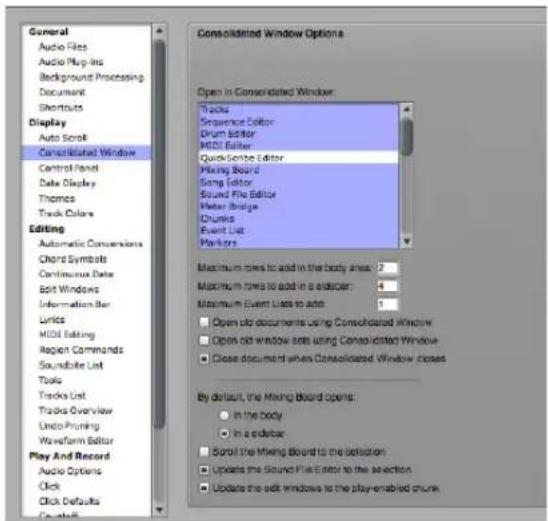
Figure 10-2: The Consolidated Window preferences.
These preferences are global (they apply across all Digital Performer projects).
Choosing which windows to display in the Consolidated Window
This preference determines what happens when you first open a window. Use the list shown in Figure 10-2 to specify which windows do or do not appear in the Consolidated Window when they are opened. Click a window to highlight (include) or unhighlight (exclude) it. If a window is included in this list, and you then go to open the window, it will open the Consolidated Window with that chosen window displayed in it. If a window is excluded, it will open as its own separate window.
During the course of using Digital Performer in a session, using a window's popout and pop-back-in areas (as explained in "Popping windows in and out" on page 117) overrides this preference. For example, if you pop a window out of the Consolidated Window and then close the window, the next time you open that window during the session, it will open as a stand-alone window. Similarly, if you pop a window back into the Consolidated Window, and then close it (close the window's cell), the next time you open it, it will appear in the Consolidated Window, even if it is turned off in the preferences. The rule of thumb is this: during a session, windows open in the location they were in when they were last closed.
Maximum rows to add in the body area
This preference controls how many rows are added to the body (center) section of the Consolidated Window when using the normal methods of opening and closing windows. However, it does not limit the number of rows you can create manually. You can always split the body into as many sections as you wish by dragging the bottom divider or by Option/Alt-dragging an intermediate divider.
Maximum rows to add in a sidebar
This preference controls how many rows are added to the sidebar sections of the Consolidated Window when using the normal methods of opening and closing windows. After the maximum has been reached, when opening a window that will open in the Consolidated Window sidebar, tabs will be added to the existing sidebar cells. However, it does not limit the number of rows you can create manually. You can always split the sidebars into as many sections as you wish by dragging the bottom divider or by Option/Alt-dragging an intermediate divider.
Maximum Event Lists to add
This preference controls how many Event Lists will be opened as separate sections in the Consolidated Window. For example, if you set the maximum to 2, then you can open two separate
Event List sections in the left or right sidebar. If you then attempt to open a third Event List, it will replace one of the two already displayed.
This preference only limits how many Event Lists will be opened when using the normal methods of opening and closing Event Lists. It does not limit the number you can create manually (using the sidebar cell menu as shown in Figure 10-5 on page 115).
Additional Consolidated Window preferences
The Consolidated Window has the following additional preferences (Figure 10-2 on page 112):
Open Old Documents Using Consolidated
Window: If you want old documents (saved in previous versions of Digital Performer) to open with their window layout preserved exactly as it was last saved, uncheck this option. If you want them to open with a Consolidated Window layout that matches your current Consolidated preference settings, check this option. For further details, see “Opening old documents” on page 118.
Open Old Window Sets Using Consolidated
Window: If you want old window sets (saved in previous versions of Digital Performer) to open with their window layout preserved exactly as it was last saved, uncheck this option. If you want them to open with a Consolidated Window layout that matches your current Consolidated preference settings, check this option. For further details, see “The Consolidated Window and Window Sets” on page 117.
Close document when Consolidated Window
closes: The Consolidated Window is considered to be the Digital Performer document window. By default, closing the Consolidated Window also closes the project entirely. Uncheck this option if you want to be able to close the Consolidated Window without closing the project.
Mixing Board default preference: This preference lets you choose where the Mixing Board opens in the Consolidated Window, by default. See “The Mixing Board” on page 115.
Scroll the Mixing Board to the Selection: If this preference is checked, and the Mixing Board is being displayed in the Consolidated Window, it will scroll to the channel strip for a track as soon as you select the track — or select some data in the track — in any editor. This option is particularly useful when you are displaying the Mixing Board in a sidebar, as demonstrated in Figure 10-1 on page 110. There is a keyboard shortcut for toggling this command in the Commands window, which you can assign to any keyboard shortcut you wish.
Update the Waveform Editor to the Selection:
If the Waveform Editor is being displayed in the Consolidated Window, and this item is checked, the Waveform Editor will always display any soundbite that you select in other editors (such as the Track Overview or Sequence Editor). There is a keyboard shortcut for toggling this command in the Commands window, which you can assign to any keyboard shortcut you wish.
Update Edit windows to Play Chunk: When this preference option is checked, editor windows (such as the Event List, MIDI Editor, etc.) will always show tracks from the currently play-enabled sequence or song. If you play-enable a different sequence or song, edit windows will update to reflect this change. There is a keyboard shortcut for toggling this command in the Commands window, which you can assign to any keyboard shortcut.
OPENING THE CONSOLIDATED WINDOW
To open the Consolidated Window, open any window that is currently configured to appear in the Consolidated Window, as explained in
"Choosing which windows to display in the Consolidated Window" on page 112. You can also open the Consolidated Window:
■ by choosing a window set that contains it, or
■ by double-clicking the pop-back-in area
(Figure 10-8 on page 117) on an individual window.
GOING FULL SCREEN
The Consolidated window supports the full-screen feature in Windows and macOS 10.7 or later. When the Consolidated window is full screen, plug-in windows float above it.
CONSOLIDATED WINDOW TITLE BAR
The title bar of the Consolidated Window has the same standard buttons as other Digital Performer windows, with one addition: the name of the project file. Command/Ctrl-click the project name to reveal a menu showing the path of the file on disk. If you click on any of the folders shown in this menu, a window will open to that folder.
OTHER WINDOW TITLE BARS
When a window is displayed in the Consolidated Window, its title bar appears at the top of the section as a Tab bar, complete with a mini-menu and other Tab bar controls that are specific to that window, as demonstrated below in Figure 10-3:

Figure 10-3: When the Sequence Editor and other windows are displayed in the Consolidated window, their title bar appears as the Tab bar at the top of the cell.
THE CONTROL PANEL
The Control Panel appears across the top of the Consolidated Window. Like other cells, it can be popped in or out. It is also highly configurable, allowing you to show and hide sections. A Compact Height option conserves even more screen space. To access these settings, visit the Control Panel preferences (Figure 7-8 on page 81), or right-click anywhere on its background (Figure 10-4 below). When displaying shortcuts and the tool bar, you can further show/hide the desired tools and shortcuts.

Figure 10-4: Right-click on the Control Panel background to configure its layout as desired.
THE BODY (CENTER) SECTION
The main body (center) section of the Consolidated Window is reserved for Digital Performer's editors and other primary windows, such as the Mixing Board. These windows are listed in the tabs across the top, and you can access any of them by clicking their corresponding tab. For information about splitting the body into several sections, see "Using Horizontal Dividers" on page 116.
THE SIDEBARS
Sidebars display list windows, monitors and legends. To open the left-hand or right-hand sidebar, double-click the divider as shown in Figure 10-3, or simply drag it towards the center of
the Consolidated Window. You can also use the keyboard shortcuts (Shift-[ or Shift-]). Likewise, to close a sidebar, double-click the divider, drag it towards the edge of the Consolidated Window, until it disappears, or use its keyboard shortcut (Shift-[ and Shift-]).
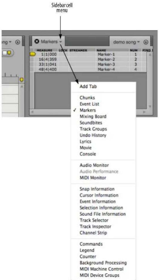
Figure 10-5: The sidebar cell menu lets you choose what is displayed in the cell.
Choosing what to display in a sidebar cell
You can choose what is displayed in a sidebar cell via a menu accessed by clicking on the current window's title, as shown above in Figure 10-5.
Resizing the sidebar
To resize the sidebar horizontally, drag its divider.
Splitting the sidebar
For information about splitting the sidebars into several sections, see "Using Horizontal Dividers" on page 116.
Using multiple tabs in one cell
Each sidebar cell contains one window by default; choosing a different window from the window selector menu will change the current window to the newly selected window.
However, you can also add additional windows within a single cell, as tabs. To add another tab, choose the "Add tab" item under the window selector menu, or hold the Option/Alt key while selecting another window.

If you add more tabs than there is space to display, a tab with a double chevron on it will appear. Click on this tab to display a menu of the tabs which are not currently visible.
To close a tab, click the "x" button on that tab. To close all but one tab in the cell, hold Option/Alt and click the "x" button on the tab that you wish to remain.
THE MIXING BOARD
The Mixing Board is a special case because it can be displayed either in the main body (center) section of the Consolidated Window or in either sidebar.
The center section is better for viewing many channels at a time. For example, you could display several dozen faders in the center section below the Sequence Editor, as demonstrated below:

Figure 10-6: Displaying the Mixing Board in the body section of the Consolidated Window. It can be placed at any vertical position you wish.
The sidebars are best for showing just one — or several — channel strips at a time, as demonstrated in the left sidebar in Figure 10-1 on page 110.
Mixing Board preference
There is a preference (Figure 10-2 on page 112) for whether the Mixing Board appears in the body or in a sidebar by default.
USING HORIZONTAL DIVIDERS
To divide the body or the sidebars into two more horizontal sections, grab the horizontal divider at the bottom of the section and drag up.
You can divide sidebars into as many horizontal sections (cells) as you like.
You can divide the body (center) into as many horizontal sections as you like, regardless of the maximum number of rows set by the preferences (Figure 10-2 on page 112).
In both the sidebar and body, you can also create additional dividers by Option/Alt-dragging an existing divider.
If you'd like to close all of the rows in the body and display only one row, Command/Ctrl-click on the tab for the window you wish to display. The window you Command/Ctrl-click doesn't have to be open already when you click on it.
DRAGGING CELLS
You can drag a window from one cell to another by grabbing its tab bar with the hand cursor and dragging it to the desired location. Some of the main tabs in the center section cannot be dragged (or displayed) in sidebar cells. But you can freely drag sidebar sections to any new location within either sidebar, as well as freely drag body sections above or below one another in the center section.
You can also drag windows out of the Consolidated Window to make them a separate window. See “Popping windows in and out” on page 117.
CELL FOCUS
In the Consolidated Window, the focus is the cell in the window with the black title (tab) bar and the gray border around it, as shown in Figure 10-7. The default colors for the title bar shading and outline border are black and gray, respectively, in DP's factory default UI theme, but the colors may be different in other themes, and they can be customized in the Theme preferences (page 83). Some operations in Digital Performer only apply to the cell that currently has the focus. It is equivalent to the active (front-most) window when you are working with multiple windows.
To apply the focus to a cell, click its Tab bar with the hand cursor. Its Tab bar turns darker and the cell gets a blue border around it. You can also use the Set Focus to Next/Previous Cell Window menu commands. You can also apply cell-related features to that cell, such as removing it as explained in the next section.
GETTING RID OF A CELL
To remove a cell from the Consolidated window, give it the focus (as explained in the previous section), and then choose Close Cell from the mini-menu. You can also click its Tab bar close button. The cell can also be moved out of the Consolidated Window by dragging it as explained above or popping it out as explained below.
POPPING WINDOWS IN AND OUT
The empty space in the Tab bar of each cell constitutes its popout button. Double-click this area to move the cell out of the Consolidated Window and make it a separate window. The keyboard shortcut for this is Control/Win-1 (which pops out the cell that currently has the focus).
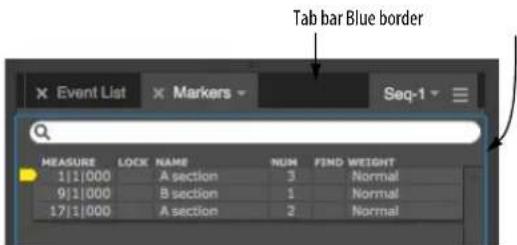
Figure 10-7: Double-click the Tab bar to extract the cell and make it an independent window.
Conversely, when windows are open on their own, double-click the Tab bar to "pop" the window back into the Consolidated Window in its original location.

Figure 10-8: Double-click the Tab bar to "pop" the window back into the Consolidated Window.
THE CONSOLIDATED WINDOW AND WINDOW SETS
The Consolidated Window integrates seamlessly with Digital Performer's Window Set features. You can save and recall window sets that include any number of different Consolidated Window layouts. You can even mix separate windows with the Consolidated Window in a window set.
Working with the Consolidated Window can feel much different than working with the separated window layouts in previous versions of Digital Performer. Therefore, you may wish to open old window sets (last saved in a previous version of Digital Performer) with the same separated window layout. You can then gradually migrate the windows in these older windows sets into the Consolidated Window at your leisure, as you get accustomed to working with the Consolidated Window.
If this is the case, uncheck the Open old window sets using Consolidated Window preference option (Figure 10-2 on page 112).
On the other hand, if you wish to directly migrate the window layout of your old window sets into the Consolidated Window as soon as you open them, then check the Open old window sets using Consolidated Window preference option (Figure 10-2 on page 112).
You can, of course, save new window sets with or without the Consolidated Window, at any time, regardless of this preference setting.
Window Set presets
Many useful preset window sets are provided for recording (tracking), editing, mixing, waveform editing, etc., as well as for emulating third-party applications. Access them in the normal fashion by choosing the Window menu > Window Sets submenu.
OPENING OLD DOCUMENTS
Working with the Consolidated Window can feel much different than working with the separated window layouts in previous versions of Digital Performer. Therefore, you may wish to open old documents (last saved in a previous version of Digital Performer) with the same window layout. You can then gradually migrate the windows in these older files into the Consolidated Window at your leisure, as you get accustomed to working with the Consolidated Window.
If this is the case, uncheck the Open old documents using Consolidated Window preference option (Figure 10-2 on page 112).
On the other hand, if you wish to directly migrate the window layout of your old documents into the Consolidated Window as soon as you open them, then check the Open old documents using Consolidated Window preference option (Figure 10-2 on page 112).
CHAPTER 11 Window Sets
OVERVIEW
The Window Sets feature in the Window menu lets you save, name, and recall your favorite window layouts. You can create as many window sets as you want. You can assign each window set to keyboard shortcuts on your computer keyboard for instant recall.
Creating a new window set....119
Choosing a window set....119
Changing an existing window set.....119
Otherwise modifying window sets ....119
Window set tips and tricks....120

Figure 11-1: Digital Performer lets you save your favorite window layouts as window sets that you can recall by name from the sub-menu shown here or by keyboard shortcuts on your computer keyboard that you've assigned to them.
CREATING A NEW WINDOW SET
To create a window set:
1 Arrange the windows on the screen the way you would like for the window set.
Digital Performer will remember the location of all windows, including edit for tracks windows.
2 Choose Save Window Set.
3 Type in a name for the window set in the dialog box and click OK.
The window set will now appear by name at the bottom of the Window Sets hierarchical menu as shown in Figure 11-1.
CHOOSING A WINDOW SET
To choose an existing window set, select it from the Window menu > Window Sets submenu, or press its keyboard shortcut if one is assigned.
CHANGING AN EXISTING WINDOW SET
To change an existing window set, use the procedure above for creating a new window set, and simply give it the same name as the existing window set.
OTHERWISE MODIFYING WINDOW SETS
Choose Edit Window Sets from the Window menu to do any of the following things to a Window Set:
■ Rename a window set
■ Delete a window set
■ Change the order of the window sets in the menu
■ Assign keyboard shortcuts to window sets

Figure 11-2: Editing Window sets.
Renaming a window set
To rename a window set, click its name in the Edit Window Sets dialog as shown in Figure 11-2 to highlight it and then click the Rename button.
Deleting a window set
To delete a window set, click its name in the Edit Window Sets dialog as shown in Figure 11-2 to highlight it and then click the Delete button.
Changing the order of window sets in the menu
To change the order of the window sets in the Window menu, click on the icon to the left of their name in the Edit Window Sets dialog as shown in Figure 11-2 and then drag them up or down as desired in the list.
Assigning a keyboard shortcut to a window set
To assign a keyboard shortcut to a window set:
1 Choose Window Sets>Edit Window Sets from the Window menu.
2 Click on the dash to the right of the window set name.
3 Press the desired keyboard shortcut.
4 Click anywhere outside the text box.
WINDOW SET TIPS AND TRICKS
When you save a window set, only edit windows from a single chunk are stored. The top-most open window that belongs to a chunk (such as a Tracks window, Event List or Song window) determines which chunk this is. If there are no open windows that belong to a chunk, the play enabled chunk is used. All editing windows that belong to the target chunk are remembered, as well as all the other non-editing windows. Edit windows that do not belong to the target chunk are ignored.
When a window set is recalled, a similar process is applied in reverse. First, the target chunk is determined by looking at the open windows — or the play-enabled chunk, if necessary. Then for each edit window type in the window set, Digital Performer looks for an existing open window belonging to the target chunk that matches the window in the set. If no existing open window is found, the system tries to open one based on the name of the track in the window when it was saved with the window set.
Part 3
Sequences and
Tracks
CHAPTER 12 Sequence Basics
OVERVIEW
Digital Performer is modeled after the straight-forward, conventional concept of a multitrack recorder. For a multitrack tape recorder, the basic unit of musical organization is a reel of tape.
Typically, one song would be recorded on one reel of tape.
In Digital Performer, the basic unit of organization is called a sequence (a term that originates from Digital Performer's roots as a MIDI sequencer). A sequence holds a set of tracks. (Think of a sequence as a reel of tape — or one section of the tape, like the chorus or the first verse.) Each track, in turn, holds an individual stream of MIDI or audio data.
Every Digital Performer project must contain at least one sequence. By default, this sequence is named "Seq-1".
Unlike analog tape, Digital Performer sequences can hold as many tracks you like.
Chunk types....123
Managing sequences, V-racks and songs ....123
CHUNK TYPES
There are three kinds of chunks: sequences, and V-Racks, and songs. Each type is described briefly below.
Sequence
A sequence is a complete performance of MIDI and/or audio consisting of any number of tracks, which are shown in the Tracks Windows, edit windows, Mixing Board, and so on. Each track contains MIDI or audio data which may be assigned to a MIDI destination or audio output. A sequence also has a Conductor track, which contains meter, key, and tempo information.
V-Rack
V-Racks™ (virtual racks) are similar to sequences, except that they have no time domain and they do not hold track data or automation. The only types of tracks that you can add to them are Instrument tracks, aux tracks and master faders. As such, they are intended to be used as “effects” racks, a centralized location for effects processing and virtual instruments.
For more information, see chapter 68, "V-Racks" (page 803).
Song
A song is a collection of chunks that you organize to play back in the preferred order and combination. Each song has its own Conductor track, end time, and markers. Each song has its own Song window, where you arrange the chunks that comprise the song.
For more information, see chapter 69, "Songs" (page 809).
MANAGING SEQUENCES, V-RACKS AND SONGS
The Chucks window lets you add, duplicate, delete, rename, and otherwise manage multiple sequences, V-racks and songs in your Digital Performer project. For complete details, see chapter 67, “Chunks Window” (page 793).
CHAPTER 13 Track Basics
OVERVIEW
Each track in Digital Performer holds an individual stream of MIDI or audio data. Each track has its own settings, input/output assignment, and a separate mixer channel. Tracks can be edited individually or together with other tracks. They can be grouped into track folders.
Basic track types....125
Special track types....126
Track settings....126
Creating a track....129
Creating several tracks at once....129
Creating multiple track types at once....129
Duplicating a track's settings ....129
Duplicating a track's settings and data....129
Renaming a track....130
Deleting a track....130
BASIC TRACK TYPES
A sequence can have the following types of tracks.
MIDI tracks
A MIDI track is where MIDI data is recorded, edited and played back. In Digital Performer, MIDI data is stored in a MIDI track without channel information. Instead, each track can be assigned to play back to one or more MIDI channels. During playback, the MIDI data in the track is transmitted to the assigned channels. Any MIDI instrument that is listening to (receiving on) that same channel will respond to the MIDI data from the track.
Audio tracks
An audio track is where digital audio data is recorded, edited, and played back. It could be a recording of a single instrument, containing any number of punch-ins and overdubs for the instrument. Or it could contain a wide variety of sounds occurring at different times, such as sound effects. You can record any audio you want into an audio track, including speech, vocals, sound effects, etc.
Instrument tracks
An instrument track is a special kind of audio track which has a virtual instrument plug-in as its first effects insert. Virtual instrument plug-ins work very much like synthesizers, samplers and other hardware instruments: you send them MIDI data and they output an audio signal. Instrument tracks do not contain MIDI or audio data, but you can insert and record mix automation data into an Instrument track. For details, see chapter 17, "Instrument Tracks" (page 155).
Aux tracks
An Aux track is a special kind of audio track that routes an input directly to an output. You cannot record audio into an Aux track, nor can you place pre-recorded audio into it. But you can insert and record mix automation data into an Aux track.
Aux tracks are primarily intended as a routing mechanism. Aux tracks allow you to route audio from any source to any destination. For example, you can route several audio tracks to a single effects plug-in that you have placed on an Aux track effects insert.
Master Fader tracks
A Master Fader track controls the overall level of a output or bus bundle. Like Aux tracks, master fader tracks have no record button, and you cannot place audio in them. Instead, the master fader track provides an output assignment and volume control and automation over the output or bus you assign to it. The most common way to use a master fader is as a sub-mix fader for an output
(or a bus) to which you have assigned a group of audio tracks. You can then control (automate, process, etc.) them as a group with the master fader.
VCA tracks
Similar to their analog mixing console counterparts, VCA tracks are used to control the relative volume, and other mixing parameters, of a group of other tracks with a single VCA track. You can create as many VCA tracks as you want in your mix, and you can even have VCA tracks control other VCA tracks as sub-groups. See chapter 19, “VCA Tracks” (page 163).
SPECIAL TRACK TYPES
In addition to the basic track types, there are two special-purpose tracks.
The Conductor track
The Conductor track stores meter, key, tempo, and marker information. For details, see the chapter 57, “Conductor Track” (page 733).
The Movie track
The Movie track is for playback and display purposes only, and is displayed only in the Sequence Editor. For details, see chapter 38, "Sequence Editor" (page 371).
TRACK SETTINGS
All basic track types have the following common track settings:
Name
■ Track type icon
■ Play/mute
■ Solo exemption
■ Output assignment
Take
■ Automation settings
■ Lock
■ Color
■ Comment
Each track type may also have additional settings which are specific to the track type. Refer to the following chapters for more information on each track type.
Name
To change the name of a track, click it while holding down the Option/Alt key and edit the text as desired in the resulting box. To confirm your change, press the Return key. To cancel the change, press the Command and period keys, or the Escape key. You can also click outside the box to confirm your edit. Use the Enter or Down Arrow key to OK the name change and move to the next track in the list. Use the Up Arrow key to OK the name change and move to the previous name in the list. The Conductor Track's name cannot be changed.
The track type icon
Digital Performer provides the following types of tracks, with the following icons to identify them in the Track List:
Icon
Track type
| Conductor track | |
| MIDI track | |
| Mono audio track | |
| Stereo audio track | |
| Quad surround audio track | |
| LCRS surround audio track | |
| 5.1 | 5.1 surround audio track |
| 6.1 | 6.1 surround audio track |
| 7.1 | 7.1 surround audio track |
| 10.2 | 10.2 surround audio track |
| Aux track | |
| Instrument track | |
| Master fader | |
| VCA fader |
Play/mute
The Play-Enable button engages a track for playback. When the button is lit, the track plays; when the button is empty, the track is muted. If muted, the data for the track is still there; you are just silencing the track during playback. Click the button to toggle between these two states.
Any number of tracks may be play-enabled at one time, but your MIDI and audio hardware resources — the MIDI devices in your studio and the audio hardware installed in your computer — ultimately determine how many tracks you can truly play all at once.
When Solo mode is engaged, clicking the play button toggles between play-enabled (blue) and muted (orange) or disabled (gray), depending on its state before entering solo mode.
The Conductor track contains no MIDI or audio data, so it therefore has no Play-Enable button.
Here are a few shortcuts for play-enabling tracks: to toggle the status of several tracks at one time, just drag ("glide") over their play buttons. To Play-enable all tracks except for one, command click its play-enable button. To play-enable only one track and unplay-enable all others, Option/Alt-click the track's play-enable button. This convention also applies throughout Digital Performer to similar toggle buttons, such as record-enable buttons, play and record buttons in other windows (such as the Sequence Editor), and Lock buttons in various windows.
For important information about track soloing and how it relates to the play-enable buttons, see "Soloing Tracks" on page 223.
Solo exemption
When you solo a track, the track you solo plays and all other tracks are muted. However, there are often tracks that should never be muted, even during soloing, such as master faders and aux returns. In addition, there might be disk tracks that you wish to always hear as you work (such as a tempo reference of some kind). For cases like these, tracks provide a setting called Solo Exempt, which appears as a column in the Track List labeled XMPT. If you click in this column for a track, it turns on solo exemption for the track.
This means that the track will not be muted when other tracks are soloed. To further indicate this, the track's solo button in the Mixing Board disappears. Master faders are always solo exempt; therefore, their setting in the Track List cannot be toggled. Aux tracks are always Solo Exempt by default (although you can defeat their exempt status, if you wish). Solo exempt status can also be toggled in the track settings menus in the Sequence Editor and the Mixing Board (below the track name).

Figure 13-1: Solo-exempted tracks will not be muted when other tracks are soloed. In this example, the track "Aux-1" and the master fader are exempted.
Output assignment
the Output column displays the destination for the MIDI or audio data in the track.
MIDI tracks, are assigned to a MIDI device in your studio followed by a dash and a MIDI channel number (between 1 and 16). It can also be a MIDI device group, which consists of several devices. The list of possible MIDI devices is provided by your MIDI device configuration (Setup menu > Bundles > MIDI Devices tab). For information, see “Choosing a MIDI output destination” on page 140, “Multiple output destinations” on page 141 and “Changing the MIDI device list” on page 141.
Audio tracks are assigned to physical outputs on your audio hardware (such as the headphone output of your computer or a pair of outputs on an audio interface), or to one of Digital Performer's internal busses. For information, see chapter, "Choosing an audio input and output" (page 149).
Take
The Take menu is used to manage track takes. For more information, see chapter 51, “Takes and Comping” (page 665).
Automation settings
This menu lets you specify various mix automation settings for the track. For details, see "Automation settings in other windows" on page 855.
Lock
When a track is unlocked (the default setting), all data in the track stays anchored to its measure location. If you change the tempo of the sequence, the SMPTE frame location of the data will change.
When a track is locked, all data in the track stays anchored to its current SMPTE frame location, even if you change the tempo of the sequence.
Color
To choose a color for a track, click on the color swatch next to the track name in the Tracks List, as shown below in Figure 13-2.

Figure 13-2: Choosing track color.
See “Track colors” on page 84 for more information on creating, using, and editing color schemes, and “Assigning colors” on page 88 for details about how to assign colors to multiple tracks at one time.
Comment
The Comment is a remark that you can display for the track. It is simply a space for text that you can use for whatever purposes you wish. To enter or change a comment, click on it and enter or edit the text. Click OK or the Enter key to confirm your entry, or press Cancel or Command/Ctrl-period (.) to cancel it. As much of the comment as possible is displayed in the Track List. If you wish to see the entire comment, click on it.
You can edit the comments for each track in succession: after bringing up a comment box, press the Down Arrow key to approve the changes you've made and move to the comment for the next track. The Up Arrow key likewise moves to the comment for the previous track.
CREATING A TRACK
To create a track, choose the desired track type from the Project menu > Add Track submenu: MIDI, mono audio, stereo audio, and so on. New tracks are added to the Track List, the Sequence Editor, and all other windows that display tracks. In addition, a fader strip is added to the Mixing Board. You can create as many tracks as you like. If a current track is selected when you add new tracks, the new tracks are added below the selected track (or the last selected track, if more than one is selected).
CREATING SEVERAL TRACKS AT ONCE
If you want to add several tracks at once, hold down the Option/Alt key and choose the desired track type from the Project menu > Add Track submenu.
CREATING MULTIPLE TRACK TYPES AT ONCE
If you want to add multiple tracks that are a mix of different track types (MIDI, audio and instrument tracks, for example), choose Project menu > Create Tracks.

Figure 13-3: Create Tracks.
Use the Consecutive output and Consecutive input options to map tracks of the same kind to the next available output or input.
If you add an instrument track to the list, and you would like to create a MIDI track for it (or each instance of it), select it in the list and enable the Add extra MIDI tracks for each instrument option.
DUPLICATING A TRACK'S SETTINGS
You can add new, empty tracks by duplicating existing tracks. To duplicate one or more tracks' layout, select the desired tracks and choose Add Similar Tracks from the Project menu. The new track will have the word "copy" appended to its name.
This command does not copy the data in the track; instead, it copies only the track's settings, such as name, input/output assignments, volume fader level, and so on.
DUPLICATING A TRACK'S SETTINGS AND DATA
To duplicate one or more existing tracks, including the contents of the tracks, select the tracks you wish to duplicate and choose Duplicate Tracks from the Project menu. The new track will have the word "copy" appended to its name.
RENAMING A TRACK
Option/Alt-click the track name to change it.
DELETING A TRACK
To delete a track, select it and choose Delete Tracks from the Project menu. The track will be removed from the sequence. Delete several tracks at once by selecting them all before choosing the Delete Track command. When a track is deleted, all of its data is gone. You can undo the Delete command. You may also assign a keyboard shortcut to the Delete Tracks command.
CHAPTER 14 Bundles
OVERVIEW
The Bundles window serves as the crucial link between the virtual mixing world in Digital Performer and the audio and MIDI hardware that is physically connected to your computer. The Bundles window provides a convenient layer between them that lets you effectively manage audio and MIDI inputs and outputs.
Audio bundles....131
Bundle types ....132
Adding and deleting bundles....132
Renaming bundles ....132
Working with tiles on the grid ....133
Exporting and importing bundles ....133
Bundle channel formats....133
Reassigning bundles ....134
Bundles and surround sound ....135
The instruments tab....135
The MIDI Devices tab ....136
AUDIO BUNDLES
Audio inputs, outputs and busses are all accessed via audio bundles. An audio bundle groups together a set of ins, outs or busses, then lets you refer to that group as a single entity. Audio bundles provide a layer of indirection between the audio assignment menus and the inputs, outputs and busses they contain. This is similar to how style sheets work in word processing programs. Instead of defining “Times, 12pt” for sections of text, you define a style called ‘Body Text’ whose properties are “Times, 12pt” This way, you can re-format your entire document by simply redefining what “Body Text” means.
In Digital Performer, you could have a large project consisting of many sequences with complex output and bussing assignments. Should you decide to switch a bus from an outboard

Figure 14-1: The Bundles window (Studio menu).
reverb to an internal plug-in, the Bundles window allows you to rewire your entire project in a single operation.
You can even change the behavior of existing bundles. If you decide you want to make a surround mix of your stereo project, simply change your primary output assignment from a stereo bundle to a surround bundle.
Bundles allow you to clean up your assignment menus, choosing only to display bundles that you'll actually use. For example, you might not need to look at 32 outputs from any single virtual instrument.
After a bundle is defined, it is available on the input and output assignment menus throughout Digital Performer.
BUNDLE TYPES
The Bundles window has tabs that display inputs, outputs, busses, instrument outputs, and MIDI devices. Click on a tab to view the type of bundle you wish to edit. Before adding or removing bundles, be sure you are looking at the correct tab.
ADDING AND DELETING BUNDLES
At the bottom of the bundles window, you will find five buttons (Figure 14-1). Click the Add button to add a single bundle, or if you need to create a number of bundles, click the Add multiple button. Bundles can be deleted by selecting a bundle and clicking the delete button. Use the Del. Unused button to get rid of all bundles shown in the list that are not currently being used in the project. The Edit button is used to modify MIDI devices, as described in “MIDI device properties” on page 137.
Creating an audio bundle from assignment menus
Anywhere in Digital Performer where you can choose an input or output assignment, such as in the Tracks window, you can also create a new bundle.

Figure 14-2: Creating a new output bundle from the Track List.
After a bundle is defined, it will remain available until the bundle is deleted.
RENAMING BUNDLES
By renaming a bundle, you can create your own names for audio inputs, outputs and busses. For example, instead of generic terms like “Analog 1”, you could name an audio input in your system “My U87 Mic”. The customized bundle name will appear in all menus that display audio inputs, outputs and/or virtual busses.
To name a bundle, double click or option click on a bundle name. When you're done, hit the return key. The enter key moves the edit field to the next bundle name.
WORKING WITH TILES ON THE GRID
The Bundles window consists of a grid where you can place and move tiles that connect audio bundles (rows) to their sources or destinations (columns). You make a connection by placing a tile in the grid square that intersects the bundle (row) with its source or destination (column).
Most sources or destinations are the physical inputs and outputs on an audio or MIDI interface, but they can also be busses inside of Digital Performer or connections to virtual instruments.
The sources and destinations available are displayed in the upper right corner of the Bundles window (Figure 14-1 on page 131). The are identified by device and then individual input or output. You may have to scroll left to right to see all available inputs and outputs for each device, especially if you are using multiple devices.
For examples, see "Reassigning bundles" on page 134.
EXPORTING AND IMPORTING BUNDLES
There are two options in the Bundles window mini-menu that allow you to exchange bundles between Digital Performer projects.
Import Bundles: Imports saved bundles into the current Digital Performer project.
Clear and Import Bundles: Clears the existing bundles and imports saved bundles into the current Digital Performer project.
Export Bundles: Exports all audio bundles for use in any other Digital Performer project.
BUNDLE CHANNEL FORMATS
After you've created a bundle, choose a channel format for it (mono, stereo, 5.1 surround, etc.) from the menu to its right, as shown below.
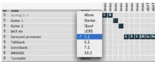
Figure 14-3: Choosing a channel format for a bundle. This determines what type of bundle it is (mono, stereo, 5.1 surround, etc.) and the number of tiles available for output and bus assignments to the right.
Audio bundle properties are bound to a hardware driver
When you create bundles, the following properties are bound to the audio hardware driver currently active in the Configure Hardware Driver dialog (under Setup menu> Configure Audio System):
■ the bundle model (mono, stereo, 5.1, etc.)
■ the bundle's physical output assignments (the arrangement of the channel tiles in the grid)
If you switch to a different hardware driver, the bundles you've created remain, but you can completely reconfigure the properties listed above without disturbing these same properties for the original hardware driver. For example, if you are working with a MOTU 2408mk3 (or other PCI-424 based audio interface), and you then switch to built-in audio, you can change the physical output assignments (move the tiles) for a bundle for built-in audio without disturbing your 2408mk3 output assignments.
This same principle applies when switching between different MOTU drivers (such as from a USB to Thunderbolt driver).
Bundles and panners
The output bundle assigned to a track determines the type of panner it has. There are three primary types of panners: Surround Panners, Stereo Panners and mono (direct). Stereo panners look and operate exactly like stereo pan knobs on a normal mixing console. Surround panners consist of a panning 'puck' inside a panner dish. The operation is similar to how a joystick works. Mono bundles remove the panner altogether, offering a direct path from the channel to the bus or output.

natural_image
Two control panel icons: a speaker with green border and a circular dial, and a play button with '0' and play buttons (no text or symbols on controls)A 5.1 surround panner Stereo panner Mono panner
(no panner)
Figure 14-4: The output bundle assigned to a track determines what type of panner it has in the Mixing Board.
A mixing board can contain multiple types of bundles and even multiple surround formats. You can mix in surround, send multiple mono outputs to a digital mixing board and create a stereo mix simultaneously.
Direct line outputs
Mono audio bundles allow you to bypass panners if you wish to use Digital Performer like a tape recorder. This is useful if you use an external mixing board to mix. In Figure 14-5 below, see eight mono bundles are routed to eight analog outputs on a MOTU 828mk3 audio interface.

heatmap
Bundles | Inputs | Outputs | Busses | Instruments | MIDI Devices | |---|---|---|---|---| | Analog 1 | Mono | Mono | Mono | Mono | | Analog 2 | Mono | Mono | Analog 4 | Mono | | Analog 3 | Mono | Mono | Analog 5 | Mono | | Analog 4 | Mono | Mono | Analog 6 | Mono | | Analog 5 | Mono | Mono | Analog 7 | Mono | | Analog 6 | Mono | Mono | Analog 8 | Mono | | Analog 7 | Mono | Mono | Analog 9 | Mono | | Analog 8 | Mono | Mono | Analog 10 | Mono | | ADAT 1 | Mono | Mono | ADAT 11 | Mono | | ADAT 2 | Mono | Mono | ADAT 12 | Mono | | ADAT 3 | Mono | Mono | ADAT 13 | Mono | | ADAT 4 | Mono | Mono | ADAT 14 | Mono | | ADAT 5 | Mono | Mono | ADAT 15 | Mono | | ADAT 6 | Mono | Mono | ADAT 16 | Mono | | ADAT 7 | Mono | Mono | ADAT 17 | Mono | | ADAT 8 | Mono | Mono | ADAT 18 | Mono | | PCI-424 Add Multiple Delete Delete Unused EditFigure 14-5: A direct line out configuration for external mixing.
Hint: if your mixing board consists entirely of mono bundle outputs, you can choose to disable the display of panners in the mixing board by using the mixing board's mini menu.
REASSIGNING BUNDLES
After a bundle is defined, you can move the assignment to another location. This is a powerful feature of bundles.
To reassign the reverb send of a an entire project to a new set of busses, simply grab the bundle tiles and move to the new assignment.
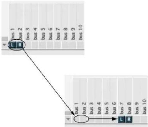
flowchart
graph TD
A["bus 1"] --> B["L-R"]
C["bus 2"] --> B
D["bus 3"] --> B
E["bus 4"] --> B
F["bus 5"] --> B
G["bus 6"] --> B
H["bus 7"] --> B
I["bus 8"] --> B
J["bus 9"] --> B
K["bus 10"] --> B
L["bus 1"] --> M["L-R"]
N["bus 2"] --> M
O["bus 3"] --> M
P["bus 4"] --> M
Q["bus 5"] --> M
R["bus 6"] --> M
S["bus 7"] --> M
T["bus 8"] --> M
U["bus 9"] --> M
V["bus 10"] --> M
Figure 14-6: Moving a bundle to a different set of outputs.
To swap the left right output of a stereo bundle, drag the bundle tile onto its opposite channel.
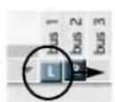

Stereo bundles can be split over non-adjacent destination pairs.

You can double-click a box to move the tiles in that row directly to the box (without having to drag them).
Surround output bundles can be rewired quickly. If you find you have mis-wired the physical outputs of your monitoring system, it may be easier to switch your output bundle than to move the physical connections, particularly if the cables are in a hard to reach spot.


Digital Performer allows you to easily mix for different surround formats by modifying the type of bundle. If you need to deliver a 7.1 version of a 5.1 mix, all you need to do is set your primary output bundle from 5.1 to 7.1.

Figure 14-7: The Bundles window allows you to change the behavior of a bundle with a pull down menu.
Audio Bundles can be created that share outputs with a surround bundle so you can directly assign audio to those outputs. For example, as shown in Figure 14-1 on page 131, you can create stereo bundles for the front and rear speaker pairs in a 5.1 mix and mono bundles for the center and LFE channels. This allows you to send audio directly to those outputs without using a surround panner.
For more information on Surround Sound, see chapter 72, "Mixing in Surround" (page 871).
THE INSTRUMENTS TAB
Some plug-ins and ReWire-compatible applications provide multiple audio outputs. You can use the Instruments tab to route them anywhere in the Digital Performer mixing environment. For details, see “Multiple audio outputs” on page 158.
THE MIDI DEVICES TAB
Once you've connected your MIDI hardware devices, you are ready to configure them in Digital Performer for use in all of your Digital Performer projects. To do so:
1 Launch Digital Performer.
2 Create a new project from the File menu.
3 Choose Studio menu > Bundles to open the Bundles window.
4 Click the MIDI Devices tab (Figure 14-8).
The MIDI devices tab lets you create and configure MIDI devices connected to your MIDI hardware. The settings you make here will be available to all Digital Performer projects. If you transfer the project to another computer system, the devices you used will be preserved so that you can easily remap them as needed.
Making MIDI connections in the I/O grid
Any connected MIDI interfaces appear across the top of the I/O grid, with their MIDI ports shown in columns beneath the interface. Use the Add buttons to create MIDI devices, which appear in the left-hand column and represent the hardware connected to the interface. Drag the MIDI in (I) and MIDI out (O) tile for each MIDI device to the appropriate MIDI interface port column (the column that represents the physical port it is connected to on the MIDI interface). For example, in Figure 14-8 the Roland JV-1080 is connected to MIDI IN port 1 and MIDI OUT port 1 on the micro express USB interface.
Devices connected directly with USB, etc.
If you have a controller keyboard or other MIDI device that connects directly to the computer with USB, Thunderbolt, or other standard computer peripheral connection, it will appear above the I/O grid in the same fashion as the MIDI interface shown in Figure 14-8 (as long as its drivers have been installed successfully). In this case, no additional I/O configuration is required and the device will be available as a MIDI input and/or output, as determined by its driver.
Renaming an interface or USB device
To rename an interface or USB device above the grid, double-click its name.
Deleting offline interfaces
If your USB MIDI interface or keyboard goes offline (it gets turned off or disconnected), its name appears in italics. If you wish to remove it from the Bundles window grid, click its name and click the Delete button.
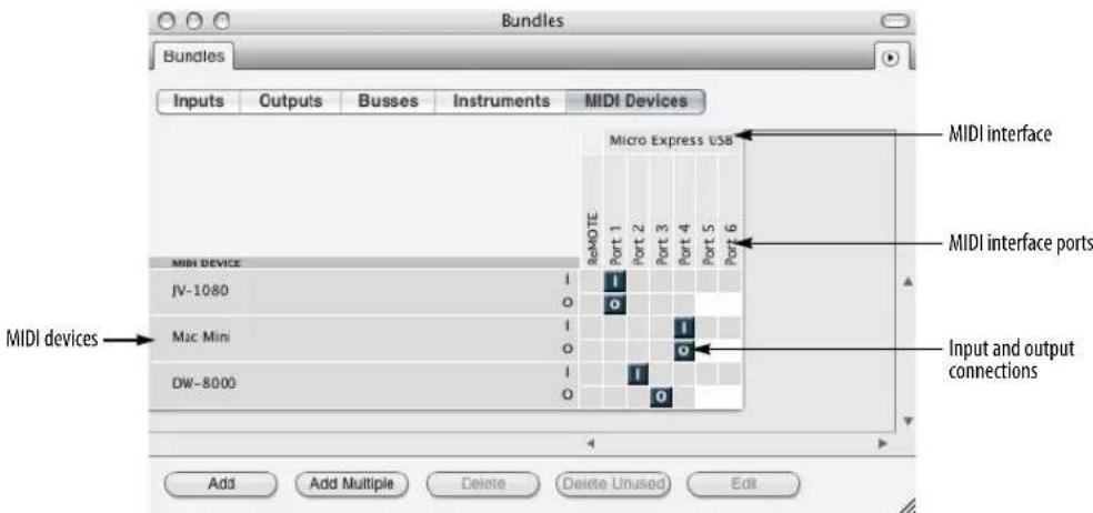
Figure 14-8: MIDI Devices tab in the Bundles window.
MIDI device properties
Click a MIDI device in the left-hand column to select it and then click the Edit button to specify the manufacturer and model for the device and to make additional device property settings (Figure 14-9).
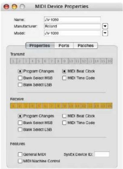
Figure 14-9: MIDI device properties.
Device
Choose the manufacturer of the device from the Manufacturer pop-up menu, then choose the model of the device from the Model pop-up menu. The Name field will be automatically filled in.
If you don't see the manufacturer or model of the device in the list, or you would like to rename it for whatever reason, you can fill in the Name field manually.
Properties and ports
Specify the properties that describe the device. For example, you can describe what MIDI channels it uses for transmitting and receiving MIDI data. Enable any MIDI data types that are supported. If the device has multiple sets of MIDI ports, configure them in the Ports tab.
Patches
If you have a device which supports expansion boards, such as the Roland JV-1080, use this section to configure which expansion cards are loaded in the device. This will ensure that your patch lists are displayed accurately.

Let's say you have a JV-1080 and would like to specify that you have the "Bass & Drums" expansion card installed. To configure Expansion Slot A Rhythm Kits, for example, locate Expansion Slot A Rhythm Kits in the Bank column on the left, then choose "EXP Bass & Drums Rhythm Kits" in the Override column.

CHAPTER 15 MIDI Tracks
OVERVIEW
This chapter covers topics that are specific to the setup of MIDI tracks for playback and recording. For audio track setup, see chapter 16, “Audio Tracks” (page 147).
Integrated MIDI and hard disk audio....139
MIDI only....139
What is a MIDI track? ....139
Creating a MIDI track ....139
Creating several MIDI tracks at once ....139
MIDI track settings....140
Record-enabling a MIDI track....140
Choosing an input source....140
Choosing a MIDI output destination....140
Making I/O assignments for multiple MIDI tracks .....141
Multiple output destinations ....141
Creating a MIDI device group....142
MIDI Drum & percussion tracks....143
Remap MIDI Devices....143
Choosing a default patch (sound)....143
The patch list....143
The current patch....143
MIDI Keys....144
INTEGRATED MIDI AND HARD DISK AUDIO
Digital Performer is designed to facilitate seamless MIDI sequencing and digital audio recording. If you would like to work with both MIDI and audio tracks, choose Setup menu >Audio System >MOTU Audio System. Digital Performer's MIDI sequencing features are available regardless of whether you use audio or not.
MIDI ONLY
If you would like to run Digital Performer as a MIDI sequencer only (no digital audio), choose Setup menu>Audio System>MIDI Only. Doing so streamlines Digital Performer for MIDI sequencing, although many “off-line” audio
features are still available (i.e. features that don't involve the real-time recording or playing of audio data). For example, you can create new audio tracks and edit existing audio data.
WHAT IS A MIDI TRACK?
A MIDI track is where MIDI data is recorded, edited and played back. In Digital Performer, MIDI data is stored in a MIDI track without channel information. Instead, each track can be assigned to play back to one or more MIDI channels. During playback, the MIDI data in the track is transmitted to the assigned channels. Any MIDI instrument that is listening to (receiving on) that same channel will respond to the MIDI data from the track.
CREATING A MIDI TRACK
To create a MIDI track choose Add Track>MIDI Track from the Project menu. New tracks are added to the Track List, the Sequence Editor, and all other windows that display tracks. In addition, a fader strip is added to the Mixing Board. You can create as many MIDI tracks as you like.
CREATING SEVERAL MIDI TRACKS AT ONCE
If you want to add several MIDI tracks at once, hold down the Option/Alt key and choose the Add Track>Multiple MIDI tracks from the Project menu.

MIDI TRACK SETTINGS
Each MIDI track has the following universal track settings:
Name
■ Track type icon
■ Play/mute
■ Solo exemption
■ Output assignment
Take
■ Automation settings
■ Lock
■ Color
■ Comment
For further details on these universal settings, see "Track settings" on page 126. Each MIDI track also has the following MIDI-specific settings:
■ Record-enable
■ MIDI input source
■ MIDI output destination(s)
■ Patch
■ Default patch
This chapter covers these MIDI track settings.
The record-enable button arms the track for recording (red). Record-enable buttons are only present if the sequence is selected for playback in the Chunks window or it is record-enabled in a Song window. Multiple audio tracks may be record-enabled at one time, although there is a preference that can restrict them to being record-enabled only one at a time, if you wish. For MIDI tracks, the Multi Record item in the Studio menu (discussed in the next section) controls this.
CHOOSING AN INPUT SOURCE
When Multi Record mode (in the Studio menu) is turned off (unchecked), a record-enabled MIDI track will record data from any MIDI channel.
When Multi Record mode is turned on (checked), each MIDI track can record from an individual MIDI device on a particular MIDI channel. This lets you record into several independent tracks from several independent sources during a single record pass. Each MIDI track displays its own incoming MIDI device and channel number next to its record-enable button. These device-specific recording assignments are only present for MIDI tracks in Multi Record mode. See “Recording several MIDI tracks in one pass” on page 245 for details.
Click on the current input source to change it. If the input assignment for a MIDI track is blank, click in the blank space to open a menu of MIDI devices. You can select only one device and channel for each MIDI track. If a device menu does not appear when you click on the blank space for a MIDI track, make sure that Multi Record is checked.
CHOOSING A MIDI OUTPUT DESTINATION
Each MIDI track has an output destination. This is where the MIDI data in the track will be sent. For example, it could be a MIDI synthesizer or sampler in your studio, connected to the computer via a MIDI interface, or it could be a virtual (software) instrument running as a plug-in with Digital Performer, or perhaps concurrently on the computer with Digital Performer.
To select a MIDI output destination, choose it from the menu provided in the Output column next to the track name in the Tracks window as shown in Figure 15-1 below. For your convenience, this same MIDI output assignment menu also appears next to each track's name in the
Sequence Editor and Mixing Board as shown in Figure 70-4 on page 828 and Figure 38-16 on page 385.
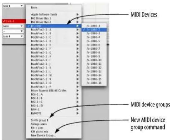
Figure 15-1: Selecting a output destination MIDI device from the menu in the Device column next to the track name.
You can choose the output destination from your computer keyboard. For details, see chapter 9, "Commands" (page 105). You can change a track's playback channel or Device at any time — even while the sequence is playing back.
The output destination MIDI device list
The devices in the output assignment list are provided by your MIDI device configuration. If a device you want is not present in the list, choose Bundles (Setup menu) and click the MIDI Devices tab to create a device in your setup. For further information, see “The MIDI Devices tab” on page 136.
For devices in your MIDI configuration, a MIDI track can be assigned to one MIDI channel on a single device. However, Digital Performer allows you to create MIDI device groups, which allow you to assign the track to several different MIDI channels and/or devices simultaneously, as described later in this chapter in “Multiple output destinations” on page 141.
Changing the MIDI device list
Digital Performer relies on your MIDI configuration for an up-to-date list of the MIDI devices connected to your computer. If a device is connected to the MIDI OUT of your MIDI interface, and the connection is accurately reflected in your MIDI configuration, then the device shows up in the output assignment list with the same name it has been given in MIDI Devices tab in the Bundles window (Setup menu). You can make any necessary changes to your MIDI device list there.
MIDI ports which do not have a device connected to them will be listed in the “Unconfigured Ports” sub-menu, as shown in Figure 15-2.

Figure 15-2: MIDI output selection
MAKING I/O ASSIGNMENTS FOR MULTIPLE MIDI TRACKS
The Track Assignments command (Studio menu) provides a convenient way to reassign MIDI inputs and outputs. Just select the tracks you wish to assign and then choose this command. For details, see “Making I/O assignments for multiple tracks” on page 151.
MULTIPLE OUTPUT DESTINATIONS
To send MIDI data in a track to multiple output destination channels and/or devices, assign the track to a MIDI device group. You can either
choose an existing MIDI device group as shown in Figure 15-1, or create a new one by choosing New Device Group, which opens the MIDI Device Groups window (described in the next section). A MIDI device group can contain up to ten MIDI channels from any combination of devices in your MIDI setup. To create a MIDI device group, read the next section.
Hint: if a track is currently assigned to a MIDI device group, and you want to make changes to the MIDI device group, Option/Alt-click the MIDI device group name in the Tracks window.
CREATING A MIDI DEVICE GROUP
A MIDI device group is a collection of individual MIDI devices, or more specifically, MIDI channels from MIDI devices. For example, a MIDI device group called Massive String Pad might include the following device channels: Kurzweil K2600 channel 1, Korg Triton channel 5, Akai S5000 channel 3, and Proteus/2000 channel 13. As a result, the MIDI device group produces a combination of the sounds currently playing on each of these MIDI channels. A MIDI device group can contain up to 10 MIDI channels.
Devices groups appear in the same output assignment list as all the rest of your MIDI devices, and they are used to assign multiple MIDI channels to a single track in the Tracks window.
To create a MIDI device group:
1 Choose MIDI Device Groups from the Studio menu to open the MIDI Device Groups window.
2 Choose Add Device Group from the mini-menu.
If you would like to add more than one at a time, hold down the Option/Alt key while selecting the command from the mini-menu.

Figure 15-3: The MIDI Device Groups window allows you to quickly assign a track to playback on multiple MIDI channels — and even separate instruments.
Here is a summary what you can do in the MIDI Device Groups window:
To do this Do this
| Rename the device group Option/Alt-click the name. |
| Add a device to the group Click the menu arrow beneath the device group name and choose the desired device and MIDI channel from the menu. |
| Add several devices quickly Click the Expand/Compress icon below the device group name to open up a display of all the devices in you studio. Then click the check boxes that corresponds to the MIDI channels you want to add to the group. |
| Close the check box display Click the Expand/Compress icon below the device group name again. |
| Remove a device Click the device and choose None from the menu. |
| Set a default patch for a device If the device is currently expanded, close it first by clicking the Expand/Compress icon below the device group name. Then click in the default patch column to the right of the device and choose the desired patch from the menu. |
Clear a default patch Click the device name to select it and choose Clear Default Patch from the mini-menu.
Remove a device or device group Click the name to select it and from the list choose Delete from the mini-menu.
Duplicate a device group Click the name to select it and choose Duplicate from the mini-menu.
MIDI DRUM & PERCUSSION TRACKS
If you are working with a MIDI drum kit that is made up of percussion sounds from multiple devices (a combination of a drum machine, sampler and a synth kit, for example), creating a MIDI device group for the drum kit is not the best way to handle this situation. Instead, it is best to create a separate track for each drum kit sound and then use the Drum Editor to work with them together in one window as a single drum kit. For details, see chapter 41, “Drum Editor” (page 451).
REMAP MIDI DEVICES
If you would like to reassign the inputs or outputs of many MIDI tracks at once, use the Remap MIDI Devices command (Studio menu).

This dialog allows you to reassign all tracks from one device to another in one step. If you don't want to change an assignment choose Don't Remap.
CHOOSING A DEFAULT PATCH (SOUND)
The default patch is the sound that the track always begins with. It is remembered when you save the Digital Performer project so that the next time you open the project and press play, the default patch is called up from the synthesizer before playback begins so that the track will play with the correct sound. To select a default patch for a track, choose it from the default patch column or menu.
THE PATCH LIST
The list of patches (sounds) you see in the Default Patch menu displays the 'factory' sound names for many popular MIDI instruments. In some cases, patches are given the generic name "Patch-1", "Patch-2", etc.

Click in the Default Patch column (Tracks List) or Default Patch menu (Sequence Editor) to choose a sound for the track. For many popular MIDI devices, Digital Performer provides a list of the factory-default sounds in the instrument.
Figure 15-4: Choosing a MIDI instrument sound from the patch menu. If you see generic names like "Patch 1, Patch 2", etc., you can go ahead and use them anyway, as long as you know what sounds correspond with each patch change number.
THE CURRENT PATCH
The Current Patch column in the Track List displays the name of the currently selected patch (sound) for the device that is assigned to the MIDI track. If a patch has not been selected, no patch name appears in the column. If you have patch changes in the track, the Patch column will update during playback to show the current patch.
If you would like to choose a patch for the track, but you do not want the patch to be remembered with the project, choose it from this Patch menu. If you do, however, want it to be remembered, choose it from the Default Patch menu.
MIDI KEYS
The MIDI Keys window (Studio menu) turns your computer keyboard into a basic MIDI controller (Figure 15-5). Keys in the “q-w-e-r-t-y” and “a-s-d-f” rows trigger an associated MIDI note event. Other surrounding keys serve as modifier keys for changing octave, changing on-velocity, applying pitch bend and applying modulation wheel. As a “virtual” controller, MIDI Keys may not be suitable for performing a Chopin Nocturne, but they do serve as a quick and convenient way to enter MIDI data when a “real” MIDI controller is not available.

Figure 15-5: MIDI Keys
Playing notes
Press the keys in the top row (W through P) and middle row (A through 'of the computer keyboard (Figure 15-5) to trigger the notes in the current octave, where the letter A is the pitch C and the letter J is the B just below the next octave.
Octave up/down
Press the minus (-) and equal (=) keys to go down or up one octave, respectively.
Octave display
Displays the current octave being played by the MIDI Keys, as controlled by the octave up/down keys. Or click anywhere on the octave display keyboard to jump directly to the desired octave.
Note-on velocity
Press the Z through period ( . ) keys to adjust the note-on velocity between 0 and 127 as follows:
| Key | Note-on velocity |
| z | 10 |
| x | 32 |
| c | 54 |
| v | 76 |
| b | 98 |
| n 120 | |
| m 127 | |
| , (comma) decrease by 1 | |
. (period) increase by 1
Pitch Bend
Press the 1 and 2 keys to apply pitch bend down or up, respectively.
Mod wheel
Press the 4 through 9 keys to apply modulation wheel as follows:
| Key | Mod wheel value |
| 4 | 0 |
| 5 | 25 |
| 6 | 51 |
| 7 | 76 |
| 8 102 |
9127
MIDI sustain
The tab and back slash () keys provide MIDI sustain (CC# 64).
Recording into a MIDI track with MIDI Keys
To record into a MIDI track with MIDI Keys, simply record-enable the MIDI track, start recording and play MIDI Keys.
Playing a virtual instrument with MIDI Keys
To play a virtual instrument with MIDI Keys, set up a virtual instrument track and a MIDI track for it as described in “Creating an instrument track” on page 155, record-enable the MIDI track and then play MIDI Keys.
CHAPTER 16 Audio Tracks
OVERVIEW
This chapter covers topics that are specific to the setup of audio tracks. For MIDI track setup, see chapter 15, “MIDI Tracks” (page 139).
Integrated MIDI and hard disk audio....147
Types of audio tracks ....147
Audio (disk) tracks....147
Mono, stereo, and surround tracks....147
Creating an audio track....148
Creating several audio tracks at once ....148
Audio track settings....148
Input source: Audio bundles....148
Choosing an audio input and output .....149
Record-enabling an audio track ....149
Input monitor enable....149
Stretch ....149
Pitch and Stretch Cache....150
Enabled 150
Monitoring an audio track input....151
Changing audio track settings on the fly .....151
Making I/O assignments for multiple tracks .....151
Managing your computer's system resources....152
Freezing tracks 152
INTEGRATED MIDI AND HARD DISK AUDIO
In Digital Performer, audio tracks are very similar to MIDI tracks, and they all appear together in Digital Performer's various multitrack windows (Tracks window, Sequence Editor, Mixing Board, and so on).
TYPES OF AUDIO TRACKS
Digital Performer provides these audio track types:
■ Audio (disk) tracks
■ Instrument tracks
■ Aux tracks
■ Master faders
Audio tracks are used for recording and playing hard disk audio. For information on Instrument tracks, Aux tracks, and Master Fader tracks, refer to the following chapters.
AUDIO (DISK) TRACKS
An audio track (disk track) is where digital audio data is recorded, edited, and played back. It could be a recording of a single instrument, containing any number of punch-ins and overdubs for the instrument. Or it could contain a wide variety of sounds occurring at different times, such as sound effects. You can record any audio you want into an audio track, including speech, vocals, sound effects, etc.
Audio (disk) tracks are the only type of audio track into which you can record or place audio. They can be mono, stereo or surround (discussed later in this chapter).
MONO, STEREO, AND SURROUND TRACKS
A mono track holds one channel of audio. A stereo track holds two channels of audio. Stereo tracks are designed to support stereo recording and editing. Mono tracks can only hold mono soundbites, while stereo tracks can only hold stereo soundbites. Stereo tracks have an input pair (i.e. in 1-2) instead of a single input, like mono tracks.
Surround tracks are multichannel tracks that may contain anywhere from four to twelve channels of audio. The number of channels in a surround track depends on the surround format chosen.
CREATING AN AUDIO TRACK
Choose Add Track from the Project menu, and then from the Add Track sub menu choose the desired type of audio track you wish to create (mono, stereo, or surround track). If you choose stereo, you'll see the inputs for the track shown as pairs (e.g. 1-2, 3-4, etc.) You can create as many audio tracks as you like, although the maximum number that you'll be able to simultaneously play and record depends on your computer.
New tracks are added to the Track List, the Sequence Editor, and all other windows that display tracks. In addition, a fader strip is added to the Mixing Board.
New audio tracks are named Audio-1, Audio-2, etc. You can rename the track by Option/Alt-clicking the name.
CREATING SEVERAL AUDIO TRACKS AT ONCE
If you want to add several audio tracks at once, hold down the Option/Alt key while accessing the Project menu and choose one of the multiple track options from the Add Track submenu.
AUDIO TRACK SETTINGS
Each audio track has the following universal track settings:
Name
■ Track type icon
■ Play/mute
■ Solo exemption
■ Output assignment
Take
■ Automation settings
■ Lock
■ Color
■ Comment
For further details on these universal settings, see "Track settings" on page 126. Each audio track also has the following audio-specific settings, discussed in this chapter:
| Setting | For further information |
| Audio Input “Choosing an audio input and output” on page 149 | |
| Record-enable “Record-enabling an audio track” on page 149 | |
| Input Monitor-enable “Input monitor enable” on page 149 | |
| Stretch “Stretch” on page 149 | |
| Pitch and Stretch Cache “Pitch and Stretch Cache” on page 150 | |
| Enabled “Enabled” on page 150 | |
In addition, the Track Settings menu (Figure 16-1) contains a few settings that are specific to the Sequence Editor window, and they are covered in "Track settings menu" on page 382.

Figure 16-1: Choosing an input and output for an audio track.
INPUT SOURCE: AUDIO BUNDLES
Audio bundles serve as the crucial link between the virtual mixing world in Digital Performer and the actual audio hardware that is physically connected to (or installed in) your computer. Bundles provide a convenient layer between them that lets you effectively manage audio and MIDI input and output. To save time, you can create bundles as part of the process of making audio track input and output assignments (as explained in the next
section). If you have a more elaborate studio setup, you can set up your audio bundles in advance using the Bundles window. For further information, see chapter 14, “Bundles” (page 131).
CHOOSING AN AUDIO INPUT AND OUTPUT
For each audio track, choose an input source and output destination as shown in Figure 16-1. The available choices in the input and output menus reflect the physical input and output jacks on the audio hardware installed in or connected to your computer. They also include any virtual instrument software running at the same time as Digital Performer.
You can choose an existing input or output (or input or output pair), or you can create a New mono bundle or New stereo bundle to assign the track to a new input or output. Or you can assign it to an input or output bundle that you created in the Bundles window, as explained in chapter 14, "Bundles" (page 131). Bundles which are already in use are bolded in input and output assignment menus, and a red dot in the input menu indicates that the input is currently record-enabled.
Output assignments
The track in Figure 16-1 above is assigned to — and panned across — the main outs of the audio interface. To play a track on a single output, pan hard left or right (where the odd numbered output is left and even is right). Alternatively, you can create a mono bundle and assign the output to that bundle.
The record-enable button (arms the track for recording). When the track is armed, the button is red.
Record-enable buttons are only present if the sequence is selected for playback in the Chunks window or it is record-enabled in a Song window. Multiple audio tracks may be record-enabled at one time, although there is a preference that can restrict them to being record-enabled only one at a time, if you wish.
To arm several adjacent audio tracks, glide the arrow cursor over their record buttons (with the mouse button held down).
INPUT MONITOR ENABLE
The Input Monitor enable button (Figure 16-1 on page 148) lets you listen to the live audio signal being received on the audio track's chosen hardware input. See “Audio input monitoring” on page 241.
STRETCH
Stretch is found in the Track Settings menu (Figure 16-1 on page 148) for audio tracks, as shown in Figure 38-13 on page 382. When this menu item is checked, the track's Stretch edit layer is enabled and all soundbites in the track that have been beat and tempo analyzed (and therefore have their own tempo map) will be stretched to conform to the sequence tempo. As a result, they will always play in time with DP's click, as well as other audio and MIDI tracks that have been recorded or sequenced in time with the sequence tempo. This is true regardless of whether the sequence is running under a constant tempo with the Tempo Slider, or with variable tempos in the Conductor Track.
When Stretch is unchecked, no stretching occurs automatically. Instead, soundbites play at their original tempo and duration. For example, if you have a dialog track or sound effects track for a movie, you would want to uncheck Stretch so that the dialog and sound effects do not get time-stretched (unless you do it manually on a per-soundbite basis).
If you lock the track ("Lock" on page 128) when the Stretch layer is enabled, doing so disables track stretching, as if it is turned off. Beat editing, however, remains available for editing.
There are preferences for enabling Stretch in the current project and new projects. See “Pitch and Stretch” on page 95.
For details about beat and tempo analysis, see chapter 53, “Audio Beats and Tempo Detection” (page 681). For details about managing soundbite tempos, see chapter 52, “Tempos and Audio” (page 673).
PITCH AND STRETCH CACHE
Pitch and Stretch Cache is found in the Track Settings menu (Figure 16-1 on page 148), as shown in Figure 38-13 on page 382. When this menu item is checked, Digital Performer stops processing audio pitch and stretch operations for the track in real time and instead caches them on disk to reduce the CPU overhead required to produce them. This processing occurs off line, in the background, so it won't affect playback performance.
If you are making pitch or stretch edits in an audio track, it is recommended that you leave this setting checked to reduce the demand on your computer's CPU, especially during playback.
The advantage to keeping this menu item unchecked is that making edits in the track's Pitch and Stretch could be a little more smooth and responsive, depending on how fast your computer is. The disadvantage is that the track will place higher overall demands on your computer's CPU, especially during playback. You can monitor this using the Real time and Cache meters in the Audio Performance panel (see “Monitoring system performance” on page 36 in the DP4 Getting Started Guide). If you notice that those meters show high activity during playback, check this menu item for any tracks that have pitch edits in them — or that have Stretch enabled.
There are preferences for enabling this cache in the current project and new projects. See “Pitch and Stretch” on page 95.
ENABLED
Audio tracks require varying amounts of computing resources, depending on the amount of mix automation data in the track, what plug-ins or instruments are instantiated on the track and other factors. The audio track Enabled option (Figure 16-2 on page 151) allows you to temporarily take an audio track off line to free up its computing resources. Note, however, that doing so causes Digital Performer to re-allocate its audio engine resource. Track enabling/disabling is not designed to produce totally smooth transitions during playback or recording. Therefore it is best done when Digital Performer is stopped. You can certainly do it during playback, but it is strongly recommended that you avoid doing so in critical listening situations.
When an audio track has been disabled, it's volume fader cap in the Mixing Board disappears, to clearly indicate that the track has been disabled.
If you wish to simply mute and unmute a track during playback (or recording), leave it enabled and use its play button to mute and unmute it. Doing so preserves the track's system resources and ensures a completely smooth transition.
Track Enable button
Each audio track has its own Enable button (Figure 16-2). In the Track list, this option is available via the Enable column, which displays an enable dot for each track. Click the dot to bring the track on line (blue) or off line (gray). In the Sequence Editor, Mixing Board and other windows that display track settings in menus, this
setting is a checkable menu item. When a track is disabled, it relinquishes all of its system resources. But note that bringing it back on line is not instantaneous.

Figure 16-2: Audio track enable.
MONITORING AN AUDIO TRACK INPUT
Digital Performer lets you listen to the live input signal being fed to a track via its chosen hardware input by “patching thru” the input signal to the track’s output destination. See “Audio input monitoring” on page 241.
CHANGING AUDIO TRACK SETTINGS ON THE FLY
When operating Digital Performer under MAS, you can change audio track input, output and send assignments while playing. However, as noted above, enabling or disabling a track entirely to free up its system resources is best done when Digital Performer is stopped.
MAKING I/O ASSIGNMENTS FOR MULTIPLE TRACKS
The Track Assignments command (Studio menu) provides a convenient way to reassign audio (and MIDI) inputs and outputs. Just select the tracks you wish to assign and then choose this command.
Tip: To quickly change the I/O assignments for all tracks, use keyboard shortcuts: Command/Ctrl-A to Select All, then Option/Alt-A to open the Track Assignments dialog.
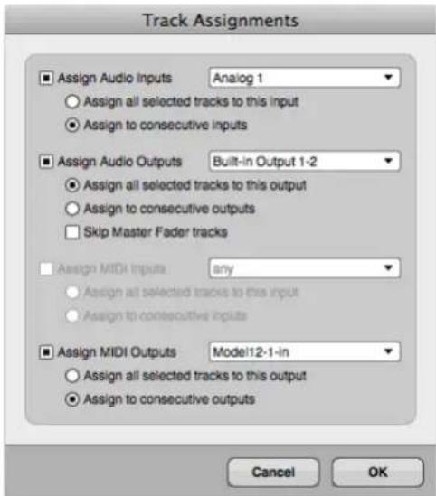
Figure 16-3: The Track Assignments feature.
Assigning inputs and outputs
You can choose to include or exclude inputs and/or outputs with the check boxes provided. You can either assign them to the same input/output pair or assign them to consecutive input/output pairs (1-2, then 3-4, etc., for example), starting with the pair that you choose in the menu.
Skipping master faders
Typically, you'll quickly select all tracks when using the track assignments feature. But master faders usually have their own special output assignment and should therefore be excluded from the audio assignment operation. For your convenience, the Skip Master Fader tracks option, when checked, causes master faders to be left alone. If, for some reason, you would like them to be included, you can unchecked this option.
MANAGING YOUR COMPUTER'S SYSTEM RESOURCES
The number of tracks you can play or record at the same time depends on the computing resources provided by your computer. See “Configuring the hardware driver” on page 27 in the DP4 Getting Started Guide to optimize your system for the maximum number of audio tracks.
Track bouncing with the Bounce command
One way to hear more tracks at once is to mix many tracks down to one track. You can do this freely in Digital Performer because in the realm of digital audio, there is no noise accumulation as a result of digital mixing. Another great advantage to digital mixing is that the original tracks remain intact, so you can always go back to them if you want (or you can delete them to free up space on your hard disk). You can even create multiple versions of a mix and quickly A/B the mixes. For more information about using the Bounce command, see chapter 84, “Bounce To Disk” (page 953).
FREEZING TRACKS
The Freeze Selected Tracks command (Audio menu) can be thought of as a “mini”, temporary bounce: it creates a new audio track, with the same output as the original track, that contains a recorded pass of the entire original track, complete with all real-time effects rendered to the track.
To freeze an audio track, aux track, or instrument track, select any portion of the track. For instrument tracks, be sure to also select the same portion of the MIDI track that is playing the instrument. Then choose Audio menu> Freeze Selected Tracks. Only the portion of the track you select is "bounced" in the freeze operation. For hard disk tracks, the new frozen track “steals” the mix engine resources of the original disk track, which becomes disabled to mute the original track and free up any system resources it takes up due to plug-ins, etc.
If you freeze a mono track assigned to a stereo output, the resulting frozen track will be a stereo track, so that it faithfully reproduces the stereo output of the original track.
This operation is especially useful for managing your computer's processing resources. It lets you temporarily freeze a track in its current state, with the option of changing the track later and refreezing it. If you make changes to the original track and refreeze it, it is “bounced” again to the same “frozen” track.
To unfreeze a disk track, select it and hold down the Shift key while choosing Unfreeze Selected Tracks from the Audio menu. Unfreezing an original disk track re-enables it, so that you can again play the original, unfrozen disk track. If you freeze the original disk track again, it once again becomes disabled. By consecutively choosing Unfreeze Selected Tracks on the original track, you can toggle the enable state between the original track and the frozen disk track (for A/B comparison or other purposes).
You can also freeze virtual instrument MIDI tracks, along with their corresponding instrument track. Select both tracks, choose Freeze Selected Tracks from the Audio menu, and the result will be an audio disk track, assigned to the same output as the instrument track, that contains the bounced instrument output. Note that after a MIDI/ instrument track freeze operation, you may need to disable the original MIDI track's play-enable button, and set the instrument track output to None. This is not done automatically because if the
instrument is multi timbral, it may still need to be able to play other tracks that have not yet been frozen.
Freezing and track mute automation
The Freeze Tracks feature takes into account track mute automation data. If you insert track mute automation, and it is enabled, then the resulting frozen track will have silence during the muted portions of the original track.
CHAPTER 17 Instrument Tracks
OVERVIEW
Virtual instruments, also called “software synthesizers” or “soft synths”, are MIDI instruments which are software-based rather than hardware-based. These appear on instrument tracks in Digital Performer.
Instrument tracks work very much like synthesizers, samplers and other hardware instruments. You send them MIDI data from a MIDI track, and their audio output signal from the output of the instrument track can be routed anywhere in the Digital Performer mixing environment.
Digital Performer provides a variety of included virtual instrument plug-ins; for details on these instruments, see chapter 2, “Instrument Plug-ins” (page 97) in the DP Plug-ins Guide. It also supports third-party virtual instrument plug-ins in its native MAS plug-in format (Mac and Windows), the VST format (Mac and Windows), and Mac OS X’s Audio Unit (AU) format. For further details about VSTs and AUs, see “Working with VST and Audio Unit plug-ins” on page 900.
Creating an instrument track ....155
Instrument track settings....156
Working with instrument plug-ins....156
Instrument tracks in the Mixing Board....157
Open Instrument shortcut....157
Instrument track automation....157
Freezing instrument tracks ....157
Instruments as audio plug-ins ....157
Instrument plug-ins in V-Racks ....157
Multiple audio outputs....158
Digital Performer's included instruments....158
CREATING AN INSTRUMENT TRACK
To create an instrument track, choose Project menu> Add Track.

Figure 17-1: Creating an instrument track.
From there, you have several choices:
- Choose Add Instruments. This opens a dialog that lets you add one or more instrument tracks and one or more MIDI tracks for each instrument at the same time.
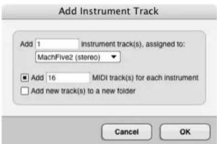
Figure 17-2: The Add Instruments dialog.
If you create multiple MIDI tracks and the instrument you choose has multiple MIDI destinations (such as the 64 individual MIDI inputs in MachFive), Digital Performer will map each MIDI track to a separate channel.
An option is also provided to place the new instrument and MIDI tracks together in a new Track Folder, if desired. Each instrument is placed in its own folder, with its MIDI tracks.
- Choose Add Unassigned Instrument. Doing so creates the new instrument track with no instrument yet assigned. You can then assign an instrument in the Mixing Board from the instrument insert, as explained later.
- Choose a specific instrument from the Instruments sub-menu. This creates an audio instrument track for it with the instrument already instantiated, but afterwards, you'll need to create a MIDI track using Project menu > Add Track > MIDI Track.
VST, AU, and MAS instruments
All instruments in all supported formats (VST, AU and MAS) appear in Digital Performer's instrument plug-in menus. You can manage which formats you wish to use, using the audio plug-in preferences. See “Plug-ins with multiple versions (formats)” on page 902.
Organizing instrument menus
Instruments are organized into several convenient sub-menus, which you can further customize using the plug-in browser. See “Choosing a plug-in for an insert” on page 829.
Unavailable instruments in the sub-menu
If an instrument is unavailable (grayed out) in the Instrument Track sub-menu, it means that there is no current audio bundle in the project that supports the instrument's audio output format (quad, 5.1, etc.) Create a bundle that matches its format, and it will become active in the menu.
INSTRUMENT TRACK SETTINGS
Each instrument track has the following universal track settings:
Name
■ Track type icon
■ Play/mute
■ Solo exemption
■ Output assignment
Take
■ Automation settings
■ Lock
■ Color
■ Comment
For further details on these universal settings, see "Track settings" on page 126. Each instrument track also has the following setting, discussed in chapter 16, "Audio Tracks":
■ Enable/disable (page 150)
WORKING WITH INSTRUMENT PLUG-INS
Instrument plug-ins work very much like synthesizers, samplers and other hardware instruments. You send them MIDI data from a Digital Performer MIDI track, and their audio output goes to the output of the instrument track itself.
When you first open (“instantiate”) an instrument plug-in, it publishes its MIDI ports, which appear in the output menu of Digital Performer’s MIDI tracks, as shown below in Figure 17-3.

Figure 17-3: Assigning a MIDI track to an instrument plug-in.
Make sure that the MIDI channel you choose matches the MIDI receive channel for the virtual instrument. If the instrument is multi timbral, such as MachFive, you can set up one MIDI track for each independent part. For example, with MachFive, which provides unlimited parts using 64 possible MIDI inputs, each playing a different preset (sound or instrument), you could set up as many as 64 MIDI tracks (on separate MIDI channels) to play the parts in one instance of MachFive.
INSTRUMENT TRACKS IN THE MIXING BOARD
Instrument tracks appear in the Mixing Board, just like other audio tracks. See “Instrument tracks” on page 840.
OPEN INSTRUMENT SHORTCUT
For instrument tracks and MIDI tracks assigned to virtual instruments, an Open Instrument shortcut is available to quickly open the instrument plug-in window. This shortcut is available in a number of ways:
■ keyboard shortcut
■ Sequence Editor track menu
■ Mixing Board track menu
■ Track Inspector/Info Bar button
If a MIDI track is not assigned to a virtual instrument, the Open Instrument command will be unavailable.
INSTRUMENT TRACK AUTOMATION
To control volume, panning, etc. for the instrument, you can use the controls on its channel strip in the Mixing Board. As with aux tracks and disk tracks, these parameters can be automated. Instrument plug-in parameter automation depends on the plug-in. If the plug-in supports automation, it is handled either via Digital Performer's control point automation features in the instrument audio track, or via MIDI continuous controller data. If the plug-in uses MIDI controllers, you can record, insert, edit and otherwise manage the MIDI controller data in the instrument's MIDI track. For example, in MachFive, you can control the filter cutoff frequency by sending MIDI Controller #74.
FREEZING INSTRUMENT TRACKS
You can conserve computer processing power by freezing instrument tracks. For details, see "Freezing tracks" on page 152.
INSTRUMENTS AS AUDIO PLUG-INS
In all other respects, instrument plug-ins work just like audio effects plug-ins. For more information, see chapter 74, "Effects Window" (page 891) and chapter 75, "Audio Effects Processing" (page 897).
INSTRUMENT PLUG-INS IN V-RACKS
If you need to use an instrument plug-in with multiple sequences in a DP project, you can conserve computer processing power by instantiating the instrument in a V-Rack, which can then be accessed from all sequences in the project. See chapter 68, "V-Racks" (page 803) for more information.
MULTIPLE AUDIO OUTPUTS
Some instrument plug-ins provide multiple audio outputs. You can access them in the Instruments tab in the Bundles window (Studio menu) as shown in Figure 17-4.
Creating instrument output bundles
To make the instrument plug-in's outputs appear across the top of the Bundles window, instantiate the instrument plug-in as usual. Then use the Add button at the bottom of the window to create as many bundles as needed in the usual fashion: choose the desired channel format, specify a name, and place the tiles on the desired channels.
Using instrument output bundles
Instrument output bundles operate just like a bus: they can be used to route audio from the instrument to any other destination within Digital Performer's powerful mixing environment. For example, you could route the instrument's output to an aux track.
DIGITAL PERFORMER'S INCLUDED INSTRUMENTS
Digital Performer includes a variety of instrument plug-ins, plus the MOTU Instruments soundbank, which provides hundreds of multi-sampled instruments. Refer to chapter 2, “Instrument Plug-ins” (page 97) in the DP Plug-ins Guide.

Figure 17-4: The Instruments tab in the Bundles window provides access to multiple outputs from instruments.
CHAPTER 18 Aux Tracks and Master Fader Tracks
OVERVIEW
Aux tracks and Master Fader tracks are special kinds of audio tracks for routing and grouping audio signals in the Digital Performer project.
Aux tracks....159
Master Fader tracks....160
AUX TRACKS
An Aux track is a special kind of audio track that routes an input directly to an output. Think of it as an individual signal path within Digital Performer's virtual mixing environment. You cannot record audio into an Aux track, nor can you place pre-recorded audio into it. But you can insert and record mix automation data into an Aux track (as well as loops).
Aux tracks are primarily intended as a routing mechanism. Aux tracks allow you to route audio from any source to any destination. Here are just a few examples: you can route disk tracks to an Aux track via a bus; you can route an input on a external audio interface (such as a MOTU 2408mk3) directly to an output. You can route several audio tracks to a single effects plug-in that you have placed on an Aux track effects insert.

Figure 18-1: Aux tracks as they appear in the Sequence Editor. They do not have a record button, and you cannot record audio into them (or place soundbites in them). They are meant to serve purely as a 'virtual' routing mechanism.
You can add as many Aux tracks as you like, and, as mentioned earlier, you can use them in many situations to get audio from here to there in your system using the Aux track's input and output assignments. For details about bussing and aux tracks, see Part 7, "Mixing" (page 819).
Using Aux tracks and Songs
If you are working with Digital Performer's Song window feature (placing multiple sequences inside a song), please keep in mind that Aux tracks, once created, always remain “active” when a song is play-enabled, regardless of which sequence is playing inside it. Be sure to manage your Aux tracks accordingly.
Conserving CPU resources with aux tracks
If you would like to apply the same plug-in to two or more audio tracks, consider assigning the plug-in to a single Aux track insert instead. Then, apply it to multiple audio tracks by bussing them to the Aux track, using either their main output assignment, a send, or both (if you'd like a bit of the original signal mixed in with the affected one). Having one plug-in with multiple inputs requires far less processing resources than applying the plug-in on multiple tracks.
Using aux tracks for live inputs such as synthesizers
You can use Aux tracks to feed live inputs (synths, etc.) into your mix. However, you may need to compensate for your system's monitoring latency. See “Audio monitoring latency” on page 242.
Monitoring with Aux tracks present
Here's a problem you may encounter when monitoring inputs: you keep hearing an input, even though you don't have any tracks record-enabled. Or, you keep hearing an input, no matter which track you record-enable.
The most likely cause of these situations is the presence of an Aux track. If you have created an Aux track that patches an input directly to an output, you'll always hear the signal from the Aux track's assigned input — unless you un-play-enable the Aux track altogether. So if you encounter monitoring problems, check your Aux tracks.
Aux track shortcut
You can create an aux track while assigning a track output or a send to a bus. The bus will then feed the track's signal to the newly created aux track.

Figure 18-2: Shortcut for routing a track to an aux track via a bus.
Aux track settings
Each aux track has the following universal track settings:
Name
■ Track type icon
■ Play/mute
■ Solo exemption
■ Output assignment
Take
■ Automation settings
■ Lock
■ Color
■ Comment
For further details on these universal settings, see "Track settings" on page 126. Each aux track also has the following setting, discussed in chapter 16, "Audio Tracks":
■ Input source (page 149)
■ Enable/disable (page 150)
MASTER FADER TRACKS
A master fader track controls the overall level of a output or bus bundle.

Figure 18-3: A master fader as it appears in the Sequence Editor. Master faders do not have a record button, and you cannot record audio into them (or place soundbites in them). They are meant to serve purely as a 'virtual' level control mechanism for outputs and busses. Notice that the track 'Master-1' has stereo outputs.
Like aux tracks, master fader tracks have no record button (or pan knob), and you cannot place audio in them. Instead, the master fader track provides an output assignment and volume control and automation over the output or bus you assign to it. The most common way to use a master fader is as a sub-mix fader for an output (or a bus) to which you have assigned a group of audio tracks. You can then control (automate, process, etc.) them as a group with the master fader. This is a great way to automate the level of a group of tracks without having to create a fader group.
Master Fader track settings
Each master fader track has the following universal track settings:
Name
■ Track type icon
■ Play/mute
■ Solo exemption
■ Output assignment
Take
■ Automation settings
■ Lock
■ Color
■ Comment
For further details on these universal settings, see "Track settings" on page 126. Each master fader track also has the following setting, discussed in chapter 16, "Audio Tracks":
■ Enable/disable (page 150)
CHAPTER 19 VCA Tracks
OVERVIEW
On large-format analog mixing consoles, a VCA (Voltage Controlled Amplifier) is a channel gain control used to adjust the volume faders of multiple tracks simultaneously. In Digital Performer, a VCA track does the same thing: after being assigned to a track group, it controls the relative volume of all the tracks in the group. It also controls the Solo, Mute and Record-enable status for all tracks in the group. In addition, VCA tracks can be automated, as explained later in this chapter. VCA tracks can be assigned to any track group, even groups that contain other VCA tracks.
VCA tracks and track groups....163
Creating a VCA track....163
VCA control....164
Shared tracks and nested VCA groups .....164
VCA tracks and mix automation ....165
Releasing a VCA track from its group....166
MIDI tracks and VCA tracks ....166
Exporting to earlier versions of DP ....167
VCA TRACKS AND TRACK GROUPS
VCA tracks depend on track groups, so be sure to familiarize yourself with this feature before using VCA tracks. See "Track Groups" on page 188.
CREATING A VCA TRACK
To create a VCA track, choose Project menu > Add Track > VCA Track. The new VCA track appears in the Track List, Sequence Editor, Mixing Board, etc. as usual. From it's output menu, choose the desired track group that you wish to control with it.
As a shortcut, you can create both the VCA track and its track group together in one operation.
First, in the Track List or Sequence Editor, select the tracks you wish to include in the group, and then Choose Project menu > Add Track > VCA Track And Group. A dialog appears for naming the group and choosing the placement for the VCA track. Click OK and a new VCA track is created, assigned to a new VCA track group consisting of the tracks selected.

Figure 19-1: VCA tracks in the Mixing Board, along with their assigned track groups.
VCA track settings
Each VCA track has the following universal track settings (“Track settings” on page 126):
Name
■ Track type icon
■ Play/mute
■ Level meter
■ Record-enable
■ Input monitoring
■ Output (see below)
Take
■ Automation settings
■ Lock
■ Color
The VCA track output menu
For VCA tracks, the output menu shows available track groups that the VCA track can be assigned to control. If two or more tracks are selected when you access the output menu, choosing Make New Group from the menu creates a new group consisting of the selected tracks, and the VCA track is assigned to the new group. If you wish to disconnect a VCA track from its currently assigned group, choose None from its output menu. See “Releasing a VCA track from its group” on page 166.
Assigning VCA tracks to non-VCA groups
You can assign a VCA track to any type of group, even non-VCA groups: Edit, Mix, Edit & Mix, or Custom. When doing so, the group converts to Custom with inherited settings from its previous group type, which you can further customize as desired. The Volume Fader setting becomes grayed out to indicate that the group is under VCA control. See “Custom group” on page 189.
VCA track level meter
The level meter in a VCA channel strip in the Mixing Board (Figure 19-1) shows the current peak level of all tracks in the VCA track group.
VCA CONTROL
VCA tracks control the following channel settings of the tracks in its assigned group.
Volume fader
Drag the VCA track's volume fader to control all the track faders in its assigned group. The grouped faders scale their position relative to the VCA fader. To adjust their faders relative to the VCA, simply move their faders. Unlike mix groups, VCA controlled faders don't affect other faders in the group. Also note that a fader can't be raised above its +6 dB max level, as scaled by its VCA fader. If you try to do so, it will snap back down to its scaled +6 dB level. VCA faders can also be automated. See “VCA tracks and mix automation” below.
Mute/Solo/Record-enable/Input monitoring
VCA track channel strips in the Mixing Board display Mute, Solo, Record-enable and Input Monitoring enable switches above the fader (Figure 19-1). These switches toggle the corresponding setting for all tracks in the group.
SHARED TRACKS AND NESTED VCA GROUPS
Tracks can be freely shared among VCA-controlled groups, so a single track could be controlled by several different VCA tracks. Similarly, you can nest VCA tracks within VCA-controlled groups, allowing you to control VCA tracks with other VCA tracks. This gives you a great deal of flexibility when setting up control of your mixes. For example, you could create several VCA groups for multi-track drum mics:
■ Kit
■ Toms
■ Overheads
■ Room
Then you could combine the VCA tracks for these four groups into another VCA group called Drums.
You could then combine the VCA track for the Drums group with VCA tracks for Bass, and Guitar groups to create another VCA group called Rhythm Section, as shown in Figure 19-2.

flowchart
graph TD
A["Rhythm Section"] --> B["DrumsBass Guitar"]
B --> C["Kit"]
B --> D["Toms"]
B --> E["Overheads"]
B --> F["Room"]
Figure 19-2: An example of nested VCA groups.
VCA TRACKS AND MIX AUTOMATION
If a VCA group track contains volume automation, the group's VCA track fader will affect that automation. In the VCA group track, the modified automation is represented by a green line, while the original automation appears as the usual black line (Figure 19-4). The green line represents what is actually played, based on the effect of the VCA fader.

line
| Time | F | |------|---| | 0 | -6 | | 1 | -6 | | 2 | -6 | | 3 | -6 | | 4 | -6 | | 5 | -6 | | 6 | -6 | | 7 | -6 | | 8 | -6 | | 9 | -6 | | 10 | -6 | | 11 | -6 | | 12 | -6 | | 13 | -6 | | 14 | -6 | | 15 | -6 | | 16 | -6 | | 17 | -6 | | 18 | -6 | | 19 | -6 | | 20 | -6 | | 21 | -6 | | 22 | -6 | | 23 | -6 | | 24 | -6 | | 25 | -6 | | 26 | -6 | | 27 | -6 | | 28 | -6 | | 29 | -6 | | 30 | -6 | | 31 | -6 | | 32 | -6 | | 33 | -6 | | 34 | -6 | | 35 | -6 | | 36 | -6 | | 37 | -6 | | 38 | -6 | | 39 | -6 | | 40 | -6 | | 41 | -6 | | 42 | -6 | | 43 | -6 | | 44 | -6 | | 45 | -6 | | 46 | -6 | | 47 | -6 | | 48 | -6 | | 49 | -6 | | 50 | -6 | | 51 | -6 | | 52 | -6 | | 53 | -6 | | 54 | -6 | | 55 | -6 | | 56 | -6 | | 57 | -6 | | 58 | -6 | | 59 | -6 | | 60 | -6 | | 61 | -6 | | 62 | -6 | | 63 | -6 | | 64 | -6 | | 65 | -6 | | 66 | -6 | | 67 | -6 | | 68 | -6 | | 69 | -6 | | 70 | -6 | | 71 | -6 | | 72 | -6 | | 73 | -6 | | 74 | -6 | | 75 | -6 | | 76 | -6 | | 77 | -6 | | 78 | -6 | | 79 | -6 | | 80 | -6 | | 81 | -6 | | 82 | -6 | | 83 | -6 | | 84 | -6 | | 85 | -6 | | 86 | -6 | | 87 | -6 | | 88 | -6 | | 89 | -6 | | 90 | -6 | | 91 | -6 | | 92 | -6 | | 93 | -6 | | 94 | -6 | | 95 | -6 | | 96 | -6 | | 97 | -6 | | 98 | -6 | | 99 | -6 | | 100 | -6 |Figure 19-4: In this example, the VCA fader controlling this track is set to +5 dB, so the track automation is scaled up by 5 dB (green line).
VCA track automation
VCA tracks can be automated, just like audio tracks. Two types of automation data are supported: volume and track mute. Automation is handled in the same fashion as audio tracks. See chapter 71, "Mix Automation" (page 851).
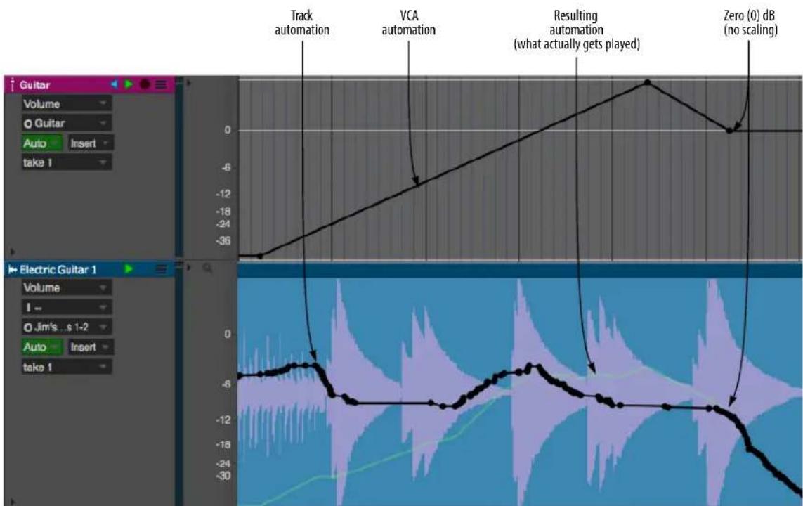
Figure 19-3: Volume automation in the VCA track scales any automation in the VCA group tracks it controls. The resulting scaled automation is shown as a green line. This is what actually gets played. Notice how the green line meets back up with the regular track automation (black line) when the VCA automation returns to zero (0) dB (no scaling).
VCA volume automation
VCA volume automation scales any volume automation in the VCA group tracks it controls. In the VCA group track, two automation curves are displayed: the original (black) and the scaled curve (green), which represents the effect of the VCA automation on the track automation. Therefore, you can always clearly see the effect that the VCA automation is having on the track automation, as shown in Figure 19-3. If multiple VCA tracks are controlling a VCA group track, their automation curves are combined in the group track to produce the resulting green line (what actually gets played).
VCA track mute automation
VCA track mute automation overrides any track mute automation in the grouped tracks controlled by the VCA track. Similar to volume automation, green lines in the group track indicate the effect of the VCA mute automation.
Setting the colors for VCA volume and mute automation
To customize the colors for VCA volume and mute automation, choose View menu > Colors > Set VCA Volume Color and View menu > Colors > Set VCA Mute Color. A standard macOS or Windows color picker appears, allow you to set the color.
To reset the colors, choose Reset VCA Colors to Default from the same sub-menu.
RELEASING A VCA TRACK FROM ITS GROUP
If you wish to disconnect a VCA track from its currently assigned group, choose None from its output menu. When you do so, you will see the alert shown in Figure 19-5.
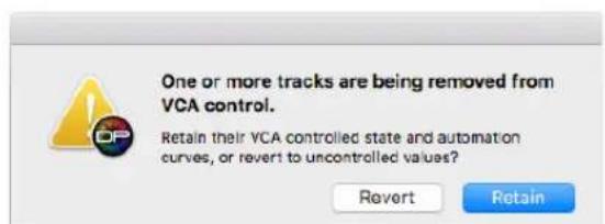
Figure 19-5: Disconnecting a VCA track from one or more tracks.
As explained earlier, VCA tracks scale the volume fader and and any volume automation of the tracks they control. If you want to retain that scaled result, even after the VCA is disconnected, click Retain. If you want the track to revert to its volume setting and/or original automation data, unaffected by the VCA, choose Revert.
MIDI TRACKS AND VCA TRACKS
MIDI tracks can be controlled by a VCA track in similar fashion to audio tracks. Automation data is displayed in green, as with audio tracks, in points, bars and lines mode, as shown in Figure 19-6. VCA mute events appear in the median strip.
Points mode

natural_image
Abstract dotted line patterns on a dark background, no text or symbols presentBars mode
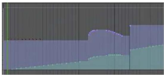
natural_image
Abstract geometric shape with layered color blocks (no text or symbols)Lines mode

natural_image
Abstract line chart with blue and green step lines on a grid background (no text or symbols)Figure 19-6: Similar to audio tracks, MIDI volume controllers scaled by VCA faders display their scaled value in green.
EXPORTING TO EARLIER VERSIONS OF DP
If you use the Save As command to save your project as a Digital Performer Version 9 project (or earlier), which does not support VCA tracks, VCA tracks will disappear from the project. In addition, group tracks with automation data being scaled by a VCA track will retain the VCA scaling, similar to clicking the Retain button in Figure 19-5. This means that the track will sound the same, even after being exported to an earlier version.
CHAPTER 20 Tracks Window
OVERVIEW
The Tracks window allows you to define and organize the contents of each sequence in your Digital Performer file. The Track List portion of the window allows you to create tracks, assign each track's input and output for recording and playback, select regions for editing, customize track names, add comments, and more. The Track Overview portion allows you to view, select, and edit MIDI and audio data together.
Quick Reference....170
Tracks Window Mini-menu....173
Opening the Tracks window....174
Sequence management in the Tracks window.....174
The Marker menu....175
The Track List....175
Working with the Track List....179
The Track Overview 181
Customizing the Tracks Window....186

QUICK REFERENCE
Track List: Displays the track names and important information about each track: the MIDI output device assignment, the current patch setting, audio track input and output assignments, the play and record buttons, comments, etc. Option/Alt-click the track name to rename it.
Track Overview: Displays the MIDI and audio contents of all the tracks. The default horizontal zoom level displays one-measure columns, but they can also be zoomed to show as much as 16 measures per segment or as little as 30 ticks. You can also vertically scale the Tracks Overview to show greater detail.
Phrases of MIDI events are shown as blocks that display a miniature representation of the events. The blocks of events can be selected, dragged, duplicated, and otherwise edited as a single event. Soundbites in audio tracks appear in miniature form, too. For a more detailed view of the events, use the Sequence Editor window.
Track Selector List: Click or drag over the names of the tracks in this list to show or hide them in the Tracks window. Option/Alt-click to hide all except the one you click; Command/Ctrl-click to show all except the one you click. Use the commands in the View menu to show/hide tracks.
Track list search: If you have many tracks, type in the name of a track to search for it. All tracks matching the text string you type appear in the track list, with all other tracks temporarily hidden.
Sequence menu: Lets you switch between sequences. When you choose a sequence from this menu, the Track List displays the tracks of the sequence.
Marker menu: Lets you jump to any marker, or other significant points in the sequence, such as the Memory Cycle points or the Auto-Record punch-in location.
Play-Enable button: Enables or disables a track for playback. To toggle its play status, simply click the button. Any number of tracks may be play-enabled. Most commonly, all tracks will be play-enabled. When solid blue, the track is play-enabled and will be audible. If orange, the track is muted or silent. If muted, the data for the track is still there; you are just temporarily silencing the track during playback.
Take menus: Each track can have an unlimited number of takes. A take stores the contents of the track. If you want to keep what is already in a track, but you want to try an alternative version of it (either recorded from scratch or based on the current take), choose New Take or Duplicate Take from the Take menu. The original data is preserved in its own take, which you can always return to by choosing it by name from the Take menu.
Track type icons: The track type icons identify the track type. See “The track type icon” on page 127.
Conductor Track: A special track that contains the tempo map, meter changes, and key signatures for the sequence. The Conductor track also contains Markers. Data in the Conductor track can be edited just like MIDI and audio data in regular tracks. The Conductor Track cannot be deleted.
Track Comments: Display remarks that you can type in for the track. To enter or change a comment, simply click on it and enter or edit the text. Press OK or the Enter key to confirm your entry, or press the Up or Down Arrow keys to
confirm your entry and move to adjacent tracks, or press Cancel or Command/Ctrl-period (.) to cancel it.
Marker: An indicator that you can create to identify an important point in the music, such as the beginning of a section or a SMPTE hit point. Create markers by dragging them from the marker well at the top of the vertical scroll bar on the right. Drag markers to move them. Command/Ctrl-drag them to freely move them without snapping to columns. Option/Alt-click or double-click the name to change it. Option/Alt-click the marker icon to toggle whether it is locked or not. To delete a marker, drag it downwards until the cursor turns into a trash can icon.
Memory Cycle strip: Displays the Memory Cycle loop as a colored bar. Drag in the strip to enable the feature and set the start and end times. Drag the endpoints of the bar to change them, or drag the bar to move it. Click the bar to toggle Memory Cycle on or off.
Playback and scrub wiper: Shows the current playback location. Click in the top half of the ruler (with the "wiper" cursor) at any location to instantly cue playback to that location. Drag the wiper to "scrub" the music. While dragging, the wiper respects grid snapping, if enabled. (The Audible Mode button in the Control Panel must be turned on for scrubbing.)
Auto Record strip: Displays the Auto Record region. Click and/or drag in the Auto Record strip to enable the feature and set the punch-in and punch-out times. Drag the endpoints to change them, or drag the bar to move it.
Time Ruler: Displays the location of each segment in any combination of Digital Performer's four time formats: measures|beats|ticks, SMPTE time, real time, or digital audio samples. Click in the top half of the ruler (with the "wiper" cursor) at any location to instantly cue playback to that location. Drag horizontally in the lower half of the ruler (with the "I-Beam" cursor) to select a time range. Shift-drag to extend the selection.
Window Target: The Window Target tab displays the name of the sequence. A Digital Performer project can contain any number of sequences, each with their own Tracks window. Click to view a different sequence in the window.
Marker well: Allows you to drag and drop an unlimited number of markers anywhere into the Time Ruler. Option/Alt-click the marker name to rename it. Drag it left and right to move it. Drag makers downwards until the cursor turns into a trash can to delete them.
Zoom Buttons: The horizontal zoom buttons zoom the Time Ruler so that each segment represents a smaller or larger duration, while the vertical zoom buttons scale the vertical size of the tracks.
For example, in the Quick Reference diagram, each segment currently represents one measure of music at the default height. Clicking the Horizontal Zoom In button will cause each segment to represent one quarter note. Other zoom-in levels are: eighth note, sixteenth note, 32nd note, and 64th notes per segment. Other zoom-out levels are: 4, 8, and 16 measures per segment. The vertical height of the tracks can also be scaled down (if you have a very large project and want to see many tracks at once) or scaled up (if you want to see each track in more detail). Option/Alt-clicking any zoom button zooms all the way in that direction.
MIDI Clips: MIDI clips are displayed with rounded corners. They can be manipulated graphically as a single object. Double-click to open the Clip Editor.
Phrase of MIDI data: When MIDI events are not grouped as clips, they are displayed as a block so they can easily be dragged, copied, duplicated and otherwise edited as a single event.
Soundbite (audio): Soundbites can be graphically manipulated in the Track overview in a similar fashion as the other editors.
Selected cell: Track Overview cells — even empty ones — can be selected and edited.
Window Divider: Separates the Track List from the Track Overview. You can grab the divider anywhere along its length and drag it left or right to resize each portion of the window proportionally. Drag left to see more of the Track Overview or right to see more of the Track List, comments, etc. If you drag all the way to the right, the Track Overview completely disappears (the divider remains). Double-click the divider to hide the Tracks List; double-click the divider again to restore it to its previous position.
Controller display: Lets you display controller levels superimposed on top of each track in the Track Overview.
Pitch and Stretch cache: Lets you toggle this feature for the track. See “Pitch and Stretch Cache” on page 150.
Stretch layer: Enables the Stretch layer for the audio track. See "Stretch" on page 149.
Current patch: If a MIDI track contains patch changes, this column displays the current patch (the one in effect at the current playback location).
Default patch: Lets you choose the patch that will initially be called up for a MIDI track when the sequence starts playing. This setting is saved with the file.
Track names: Click a track name to select the track (or a portion of it) for editing. Option/Alt-click a track name to rename it. Double-click or Command-double-click it to open editing windows for it. Drag over adjacent tracks to select several at a time. You can Shift-click tracks to select a contiguous range of tracks, or Command/Ctrl-click to select tracks that aren't next to each other.
Audio track enable/disable: Brings the audio track on line (or takes it off line). See “Enabled” on page 150.
Output menu: Each track has an output assignment, which can be selected from a menu by clicking in this column next to the track. MIDI tracks are assigned to a MIDI device (channel) or a combination of several devices (several channels). Devices in the menu are provided by your MIDI device configuration (Setup menu > Bundles > MIDI Devices tab). Audio tracks are assigned to physical outputs on your audio hardware (such as the headphone output of your computer or a pair of outputs on a MOTU audio interface), or to one of Digital Performer's internal busses.
Solo Exemption: When enabled, this button prevents the track from being muted when solo mode is engaged.
Track Color: Lets you choose a color for the track. See "Color" on page 128 in chapter 13, "Track Basics".
Activity Meters: Indicate the intensity of playback coming from the track. For MIDI tracks, they monitor either note-on velocities or amount of data, including controllers and any other types of MIDI data. For audio tracks, the level meters provide a rough indication of audio level. For a more accurate level reading, use the full length level meters in the Mixing Board.
Input menu: Choose the desired source for recording into the track. For audio tracks, the input sources shown in this menu are provided by the hardware driver. In many cases, such as the PCI-424 driver for MOTU PCI audio interfaces, you can enable and disable inputs as needed. Enabled inputs appear in this menu. For MIDI tracks, this menu is only available when Multi Record mode is enabled (checked in the Studio menu) and it lets you choose a specific device and MIDI channel to record from. When Multi Record is turned off, MIDI tracks record any MIDI input received by Digital Performer.
Input Monitor toggle: Lets you enable or disable live input monitoring for the audio track. See "Audio input monitoring" on page 241.
Record-enable button: Arms the track for recording (red). Record-enable buttons are only present if the sequence is selected for playback in the Chunks window or it is record-enabled in a Song window. Multiple audio tracks may be record-enabled at one time, although there is a preference (Setup menu) that can restrict them to being record-enabled only one at a time, if you wish. For MIDI tracks, the Multi Record item in the Studio menu controls this. When Multi Record is checked (enabled), you are allowed to record-enable two or more MIDI tracks at a time, and each record-enabled track allows you to specify a single MIDI device (and channel) for input. When Multi Record is off, only one MIDI track can be armed for recording at a time.
Track locking toggle: Locks or unlocks the track. When a track is locked, all data in the track stays anchored to its current SMPTE frame location, even if you change the tempo of the sequence.
Show/hide track selector: Opens and closes the track selector.
Move Handle: Drag up or down to change the position of a track in the Track List.
TRACKS WINDOW MINI-MENU
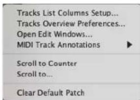
Figure 20-1: The Tracks window mini-menu.
Tracks List Columns Setup: Displays the track columns setup preferences. See “Showing and hiding columns in the Track List” on page 176 for details.
Tracks Overview Preferences: Displays the tracks overview preferences. For details, see "Configuring the MIDI activity meters" on page 177 and "Customizing MIDI phrasing blocks" on page 182.
Open Edit Windows: This is the same as double-clicking a track to open its default editor window.
MIDI Track Annotations: Lets you quickly add (or remove) information about MIDI playback device and patch settings to track names and comments. See “MIDI track device and patch annotations” on page 179.
Scroll To Counter: Scrolls the graphic display to the time currently displayed in the Counter. The counter location will appear at the left-most position in the window.
Go To: Scrolls the graphic display to a time you specify, which will appear at the left-most position in the window.
Clear default patch: Removes the default patch assignment in the Default patch column for the currently selected MIDI tracks.
OPENING THE TRACKS WINDOW
To open the Tracks window, choose Tracks from the Project menu. Like the other windows in this sub-menu, the Tracks window is bound to a particular sequence (explained in the next section). You can also open the Tracks window by clicking the Tracks window tab in the Consolidated Window:

Figure 20-2: This tab in the Consolidated Window opens the Tracks window. If your Digital Performer project has multiple sequences, this button opens the Tracks window for the currently play-enabled sequence.
You can also open the Tracks window by double-clicking the sequence name in the Chunks window (as described in “Opening chunks” on page 798).
Opening multiple tracks windows
If your Digital Performer project contains more than one sequence, you can open more than one Tracks window at a time (one window for each sequence) using any of the methods described in the previous section. The Tracks window has many features for working with multiple sequences, as explained in the next section. For further details about working with multiple sequences in a Digital Performer project, see chapter 67, “Chunks Window” (page 793).
SEQUENCE MANAGEMENT IN THE TRACKS WINDOW
The Tracks window displays one sequence at a time. That is, it displays all tracks in a single sequence. The Tracks window provides several features for working with multiple sequences, if your Digital Performer project has them.
Making the Tracks window display a different sequence
You can create an unlimited number of sequences in a Digital Performer project. You can make the Tracks window display any sequence you want by choosing it from the Sequence menu shown below. Doing so causes Digital Performer to display the sequence's tracks in the list; in addition, the sequence name is displayed in the Window Target menu of the Tracks window. It also play-enables the sequence being viewed. If the Tracks window is displaying a sequence that is not play-enabled, then this menu will appear blank.

Figure 20-3: The Sequence menu lets you display a different sequence in the Tracks window.
Using the Window Target to switch sequences
You can also use the Tracks window Window Target menu to change which sequence is displayed. To do so, just click the sequence name in the title bar's Window Target menu as shown below. Note, however, that this method of switching sequences is slightly different than using the Sequence menu as described above because it doesn't play-enable the sequence; it only switches the display. If you want to hear the sequence you are switching to, use the Sequence menu.

Figure 20-4: You can also switch the sequence being displayed in a Tracks window by clicking the Window Target menu.
Creating new sequences in the Tracks window
When you choose New from the File menu to create a new Digital Performer project, the newly created project that appears on your screen
contains a single empty sequence named "Seq-1", which is displayed in the Tracks window. You can use the Sequence menu to create other new sequences. Just choose either New Sequence or Copy Selection to New Sequence (as explained in "Making a new, separate sequence based on the current selection" on page 175.)

Figure 20-5: The Sequence menu also provides commands for creating, naming, and deleting sequences, as well as copying the current selection to its own, new sequence or V-Rack.
Renaming and deleting a sequence in the Tracks window
The Sequence menu shown above lets you also rename or delete any sequence. Just choose the sequence by name from the menu, and then choose the desired command.
Making a new, separate sequence based on the current selection
The Copy Selection to New Sequence command in the Tracks window Sequences menu (as shown in Figure 20-5 on page 175) creates a new, separate sequence based on the current selection. For details see “Splitting up an existing sequence into separate chunks” on page 796.
Opening two or more Tracks windows at once
As mentioned earlier, you can freely switch which sequence is displayed in the Tracks window. If you'd like, you can also open multiple Tracks windows so that you can view two or more sequences at the same time. Just double-click its name in the Chunks window.
THE MARKER MENU
The Marker menu, as shown in Figure 20-6, contains markers and other significant locations in the sequence. Use it to conveniently and instantly jump to any location in the sequence.

Figure 20-6: The Marker menu lets you instantly cue to any marker, Memory Cycle loop point or Auto-Record point.
THE TRACK LIST
The Tracks window is divided into two portions, as shown in Figure 20-1 on page 173: the Track List on the left and the Track Overview on the right. The following sections discuss the Track List. For the Track Overview, see “The Track Overview” on page 181.
The Track List provides a list of all the tracks in the sequence. In addition, it shows all of the settings for each track, such as the track's output assignment. This information is shown in the same row as the track, as shown in Figure 20-1.
Customizing the Track List
You can customize the Track List display to suit your tastes. You can hide columns you don't wish to view, and you can rearrange the order of the columns. For example, if you don't have any comments, you don't need to display the column.
Showing and hiding columns in the Track List To hide or show columns in the Track List, choose Track List Columns Setup from the Tracks window mini-menu. As a shortcut, you can double-click any column heading instead. The Column Setup preferences appear.

Figure 20-7: Showing and hiding columns in the Track List.
Changing column order You can rearrange the order of the columns simply by dragging the title of the column left or right.
See “Customizing the Tracks Window” on page 186 for an example of a more compact, customized Track List.
The move handle The move handle allows you to shift the position of a track in the Track List. Use it to rearrange the tracks in an order that is most useful to you. To use the Move Handle, press on it and drag the track where you want it to go.
Lock button "Lock" on page 128 in chapter 13, "Track Basics".
Audio track enable/disable Brings the audio track on line or takes it off line, which frees up computer system resources. See "Enabled" on page 150.
The record-enable button The record-enable button arms the track for recording. When the track is armed, the button is red.
Record-enable buttons are only present if the sequence is selected for playback in the Chunks window or it is record-enabled in a Song window.
Multiple audio tracks may be record-enabled at one time, although there is a preference (Setup menu) that can restrict them to being record-enabled only one at a time, if you wish. For MIDI tracks, the Multi Record item in the Studio menu controls this. When Multi Record is checked (enabled), you are allowed to record-enable two or more MIDI tracks at a time, and each record-enabled track allows you to specify a single MIDI device (and channel) for input. When Multi Record is off, only one MIDI track can be armed for recording at a time.
To arm several adjacent audio tracks (and/or MIDI tracks when Multi Record is enabled), glide the arrow cursor over their record buttons (with the mouse button held down).
The Conductor Track has a record-enable button, which is used to record tempo information while slaved to Tap Tempo synchronization. See chapter 86, "Receive Sync" (page 977) and "Using Tap Tempo while slaved to external sync" on page 987 for details on using Tap tempo to record a tempo map in real time.
Input monitor button Lets you listen to the live audio signal being received on the audio track's chosen hardware input. See "Audio input monitoring" on page 241.
The input column
The input column displays the source for MIDI or audio data to be recorded into the track. For MIDI tracks, see “Choosing an input source” on page 140. For audio tracks, see “Choosing an audio input and output” on page 149.
Levels (activity) meters
The level (activity) meters act very much like the level meters on a tape deck: when there is signal on the channel, the level meter registers the signal. Similarly, at the moment a MIDI track plays data, the activity meter registers the outgoing MIDI data. For audio tracks, the activity meters register audio level, although not with as much resolution as the level meters in the Mixing Board.
Configuring the MIDI activity meters
To configure the MIDI activity meters choose Tracks Overview preferences from the mini-menu to open the MIDI Level Meters preferences shown below. These settings are global across files and are automatically saved in the Digital Performer Preferences file.
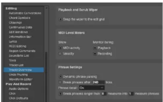
Figure 20-8: The Level Meter setup feature lets you customize the behavior of the MIDI activity meters in Track List.
Showing MIDI activity or velocity
MIDI activity meters can show either the presence of MIDI data (activity) or note-on velocity. With MIDI activity, the meter is triggered every time a MIDI event is played back from the track. It can be any type of MIDI data, including notes, controllers, pitch bend, sysex data, etc. With velocity, the level meter reflects the note-on velocity of each note at the instant the note is triggered during playback.
MIDI activity meters do not function like audio level meters. For both MIDI activity and velocity, the MIDI level meter is triggered by a MIDI data byte, such as a note-on event or controller, at the time it is played back. The level does not sustain during the duration of the note.
Monitoring
Activity meters can monitor MIDI data being played back, recorded, or both. With both options checked, the meters monitor playback when you are playing back, and they monitor recorded material on the current record-enabled track during recording. If you are in overdub record mode, both recording and playback are monitored at the same time for the record-enabled track.
We recommend using both options because this gives you the greatest amount of feedback about what is going on in your tracks.
Hiding activity meters to reduce overhead
Digital Performer goes to great lengths to preserve the integrity of MIDI playback. Screen display takes a back seat to the more important function of playing back the sequence with as accurate timing as possible. However, the activity meters do require some effort from Digital Performer. In some situations, such as running Digital Performer on a slower computer, it may be desirable to hide the activity meters to ensure the highest playback performance.
To hide the activity meters, double-click the track column heading above the meters (labeled "LEVEL") to open the Track Columns Setup dialog box as shown in Figure 20-7. Uncheck the Levels option.
If you'd rather not hide the meters, another overhead-reducing tactic is to monitor MIDI activity instead of velocities because MIDI activity monitoring requires less effort. Open the Level Meters Setup dialog (Figure 20-8 on page 177) and select the MIDI Activity option.
Other metering options
Longer throw meters are available in both the Mixing Board (“Level meters” on page 839) and the Meter Bridge (“Meter Bridge” on page 885).
Play-enable button
See “Play/mute” on page 127 in chapter 13, “Track Basics”.
Solo exemption
See “Solo exemption” on page 127 in chapter 13, “Track Basics”.
Output assignment
See “Output assignment” on page 128 in chapter 13, “Track Basics”.
The Take column
See chapter 51, "Takes and Comping" (page 665).
Audio track enable/disable
Audio tracks require varying amounts of computing resources, depending on the amount of mix automation data in the track, what plug-ins or instruments are instantiated on the track and other factors. The audio track Enable/Disable option allows you to temporarily take an audio track off line to free up its computing resources. See “Enabled” on page 150.
The Track Type icon
See “The track type icon” on page 127 in chapter 13, “Track Basics”.
The track name
See “Name” on page 126 in chapter 13, “Track Basics”.
Track color
See “Color” on page 128 in chapter 13, “Track Basics”.
The current patch (MIDI tracks only)
This column displays the name of the currently selected patch (sound) for the device that is assigned to the MIDI track. If a patch has not been selected, no patch name appears in the column. For further details, see “The current patch” on page 143.
The default patch (MIDI tracks only)
The default patch is the sound that the track always begins with. It is remembered when you save the Digital Performer project so that the next time you open the project and press play, the default patch is called up from the MIDI instrument before playback begins so that the track will play with the correct sound. For further details, see “Choosing a default patch (sound)” on page 143.
Automation menu (ATO)
This menu lets you specify various mix automation settings for the track. For details, see “Automation settings in other windows” on page 855.
Stretch (STC)
The Stretch setting is for audio tracks only. See "Stretch" on page 149.
Pitch and Stretch Cache (CSH)
The Pitch and Stretch Cache settings is for audio tracks only. See “Pitch and Stretch Cache” on page 150.
The controller display (CNTRL)
The controller display column lets you display controller levels superimposed on top of each track in the Track Overview. Press on the empty space in this column to open a menu, which allows you to choose what controller to display. The
options you see in the menu depend on what types of controllers or automation are being used in the track.
The comment
"Comment" on page 129 in chapter 13, "Track Basics".
The Conductor track
The Conductor track is a special track containing markers, meter, tempo and key change information. Every sequence always has a Conductor track; it cannot be deleted. In the Tracks window, the Conductor track has a Move Handle and Comments. The Conductor track cannot be looped. Certain editing commands can be used on the Conductor track. For more information, see chapter 57, “Conductor Track”.
MIDI track device and patch annotations
The Tracks window mini-menu contains a sub-menu full of commands for quickly adding information about MIDI playback device and patch settings to track names and comments. This feature is especially useful before exporting standard MIDI files because it allows information about the playback device and patch for each track to be included in the text of the track name or comment. This information would not otherwise be included in the standard MIDI file.

Figure 20-9: The MIDI track annotations sub-menu.
The commands in the MIDI Track Annotations menu affect all MIDI tracks. Use the four checkable items at the bottom of the menu to determine what will be included in the text that will be copied to the track name or comment. Then choose the desired operation from the upper portion of the menu.
![TRACK NAME Conductor Track-2/Apple Software Synth-1[Tuba] Track-3/Apple Software Synth-2[String Ensemble 1] Track-4/Apple Software Synth-3[French Horn] Track-5/Apple Software Synth-4[Turmpet] Track-6/Apple Software Synth-5[Tremolo Strings] Track-7/Apple Software Synth-6[Tremolo Strings] Track-8/Apple Software Synth-7[Tremolo Strings] Track-9/Apple Software Synth-8[String Ensemble 1] Track-10/Apple Software Synth-9[Trombone]](/content/2026/05/834832/images/11d3de1e6910f85f6c39f9fac7e953e5d99dade06708be9eb52af34fadd8fcab.jpg)
Figure 20-10: In this example, device name and current patch annotations have been copied to track names.
To remove annotations, choose one of the two Remove Annotations commands. Annotations are preceded by a forward slash (/) or a colon (:). When removing them, all text to the right of a forward slash and/or colon in the track name text or comment text will be removed.
WORKING WITH THE TRACK LIST
The following sections describe the many ways in which the Track List helps you manage your Digital Performer project.
Creating a new track
To create a new, empty track, choose Add Track from the Project menu and choose the type of track desired from the sub-menu (MIDI track, mono audio track, stereo audio track, etc.) The new track is added to the bottom of the list with the name “Track-n”, where n is a number. If you would like to add the track somewhere in the middle of the Track List, click an existing track first to highlight it. The new track is added just below the highlighted track.
To add several tracks at once, hold the Option/Shift key and choose one of the multiple track options from the Add Track menu in the Project menu. You will be prompted for the number of tracks to add. You can add as many tracks as you wish to the Track List.
Creating multiple tracks at once
Use the Create Tracks command (Project menu) to quickly create many tracks in one operation. See “Creating multiple track types at once” on page 129.
Track folders
Track folders allow you to visually group, collapse, and manipulate multiple tracks in any window that displays tracks, including the Tracks window, Sequence Editor, Mixing Board, QuickScribe Editor, etc. For details, see chapter 21, “Track Folders and Track Groups” (page 187).
Showing and hiding tracks
Use the Track Selector list (“The track selector list” on page 342) to show and hide tracks. Shortcuts for showing and hiding tracks are provided in the View menu. See “Show/Hide Tracks” on page 326.
Reordering tracks
Use a track's move handle (Figure 20-1 on page 173) to move it up or down in the track list. If multiple tracks are selected (even a non-contiguous selection), you can grab the move handle of any selected track to move them all together as a group to the destination location in the list, where they are placed in order (top to bottom). If you wish to cancel the operation after you've started dragging, simply drag outside the list.
Creating and saving track layouts
You can take a snapshot of which tracks are currently shown and hidden and save it for future recall. See “Track Layouts” on page 327.
Duplicating track layouts
“Duplicating a track’s settings” on page 129 in chapter 13, “Track Basics”.
Duplicating tracks
“Duplicating a track’s settings and data” on page 129 in chapter 13, “Track Basics”.
Transferring tracks to another sequence
The Track Overview allows you to duplicate tracks and even transfer them to another sequence. See “Track copying and transfer via drag & drop” on page 185.
Selecting tracks
There are many reasons for selecting tracks. For example, to select data for editing or delete a track, you must first select the track. There are several methods for selecting tracks:
To select a single track, click on its name. It will highlight.
To select several adjacent tracks, press on a track name and drag over the desired names. All tracks dragged over will highlight. You can also click on the first track, the hold down the Shift key and click on a second track to select all tracks between the first and second tracks you clicked on.
To select several non-adjacent tracks, hold down the Command/Ctrl key and click on the names of the tracks you wish to select. They will highlight.
To deselect tracks when more than one are highlighted, hold down the Command/Ctrl key and click on the tracks you wish to deselect. They will unhighlight.
Selecting tracks for editing
The track selection techniques are also used to select data inside the tracks for editing with Digital Performer's powerful Edit and Region menu commands. For complete details, see “Selecting a time range in the Selection Information window” on page 551.
Deleting tracks
"Deleting a track" on page 130 in chapter 13, "Track Basics".
Opening an edit window for a track
The Edit windows display the MIDI or audio data in a track for detailed viewing and editing. Each track has several event editing environments to choose from: the Event List, the MIDI Editor, the Notation Editor, the QuickScribe Editor, the Drum Editor and the Sequence Editor. In these windows, the location and other details for each event are expressed numerically, graphically, or as music notation. You can edit, add and delete events in these windows as well as select regions of events to be modified by commands from the Region menu.
To open an edit window, highlight the track name or an event in the track and click as follows:
To open this Do this
| Your default editor (as specified in Preferences) | Double-click |
| Event List Command-Option/Ctrl-Alt-double-click | |
| MIDI Editor Command/Ctrl-double-click a MIDI track | |
| MIDI Drum Editor Command-Control/Ctrl-Win-double-click a MIDI track | |
| QuickScribe Editor (MIDI) Control/Win-double-click a MIDI track | |
| Notation Editor (MIDI) Option-Control/Alt-Win-double-click a MIDI track | |
| Sequence Editor Shift-Control/Shift-Win-double-click Or Double-click an audio track or soundbite | |
For your convenience, the Preferences command in the Digital Performer menu (macOS) or Edit menu (Windows) lets you decide which window opens when you double-click a track. For more
information, see chapter 7, “Preferences and Settings” (page 77). For a detailed explanation of event editing, see Part 5, “Editing” (page 323).
THE TRACK OVERVIEW
The Track Overview portion of the Tracks window provides you with a global view of the MIDI and audio data in a sequence. It is useful for getting a “bird’s eye” view, arranging parts among tracks, using edit commands such as Cut and Paste, and other region operations that affect more than one track at a time. It allows you to view and edit the data in your sequence all at once instead of one track at a time.
For more detailed editing of MIDI and audio tracks together, see chapter 38, "Sequence Editor" (page 371).

Figure 20-11: The Track Overview is designed to give you a "bird's-eye" view of your music.
The time ruler
The Time Ruler displays time as regularly spaced columns labeled in any one of Performer's various time formats. By default, one column equals one measure of music (regardless of meter). You can, however zoom the columns with the +/- buttons in the horizontal scroll bar to show many
measures per column (for an even greater overview) or as little as 30 ticks (for microscopic precision). To change time formats, choose Time Formats from the Setup menu.
The Time Ruler can also display markers. See “Working with markers in the Time Ruler” on page 185.
Clips
The Track overview displays MIDI and audio clips as colored blocks of data with rounded corners. You can select, drag and edit them as objects, similar to the other graphic editors. Their edges, however, cannot be trimmed in the overview. Use the Sequence Editor or MIDI Editor for trimming. Double-click a clip to open the Clip Editor.
Audio data
Soundbites (that are not contained within a clip) are displayed as blocks with square corners containing a waveform. They are selected and edited as single events. Their edges cannot be trimmed in the overview. Use the Sequence Editor or Waveform Editor for trimming.
MIDI data
MIDI data (that is not contained within a clip) is displayed as phrase blocks with square corners containing a miniature representation of the MIDI notes inside the block. Digital Performer automatically determines how to group data into blocks. The blocks of events can be selected, dragged, duplicated, and otherwise edited as a single event, similar to clips. Clips, however, give you precise, manual control of the length of the clip and the MIDI data it contains.
Customizing MIDI phrasing blocks
The Phrase setup settings in the Tracks Overview preferences (Figure 20-8 on page 177) lets you customize the way that data is phrased in the Track Over view.
Phrase Setup settings are saved with the project file, which allows you to choose different settings for different projects. You can also choose the desired settings for your new file template. (See "Creating project templates" on page 28 for details.)
Dynamic Phrase Parsing
This is Digital Performer's special algorithm for determining how events should be grouped into phrase blocks. Dynamic Phrase Parsing does much more than just separate blocks of events by a certain minimum amount of empty time. It looks at overall event density and takes a number of factors into account. The result is a more musical organization.
Break Phrases After \_\_\_\_ Ticks
This option gives you a simple, straightforward way of controlling where phrases begin and end. The number of ticks that you enter determines how much space there must be for a phrase to end and another one to begin.
Phrase Detail
The term Phrase Detail refers to the miniature representation of the MIDI data you see inside each phrase block. The Phrase Detail menu gives you several choices for how this detail is displayed so that you can control the trade-off between a high degree of detail versus the Track Overview's
responsiveness when scrolling, zooming and other redraw operations. Here is a summary of the three possibilities:
Phrase detail setting Explanation
| On Phrase detail is always computed before any redrawing happens. This setting produces the best-looking results, but it is also the slowest in redrawing. If you are running Performer on fairly slow computer, you will probably find one of the other two options to be more convenient. |
| On Demand Phrase blocks are initially shown by their outline when redrawing, and detail is filled in after you stop scrolling, zooming or otherwise redrawing the Overview. This setting is faster than above, but it is not quite as elegant. |
Off Phrase detail is completely turned off. Instead, phrase blocks are filled with a generic pattern. This setting definitely produces the fastest redraws, but it is, of course, missing all detail.
Folder contents overview
Folders show an overview of their contents in the Tracks Overview. When the folder is collapsed, the overview reflects the colors of the individual tracks contained in the folder; when the folder is expanded, the overview is grayscale (see Figure 20-12, below).
Modifier key shortcuts in the Track Overview
Here is a summary of modifier key shortcuts that will save you time when using the Track Overview:
To do this Use this shortcut
| Extend the current selection Hold down the Shift key while clicking or dragging | |
| To make a duplicate copy of the selected data (or a time range selection) | Option/Alt-drag the selected data or time range |
| Override the current grid snapping setting | Hold down the Command/Ctrl key while dragging (in combination with any of the above modifiers, if desired) |
Clicking the time ruler for selecting and cueing
Click in the top half of the ruler (with the "wiper" cursor) at any location to instantly cue playback to that location. Drag horizontally in the lower half of the ruler (with the "I-Beam" cursor) to select a time range. Shift-drag to extend the selection. Any of these operations can be done while playing back.
Temporarily suspending scrolling during playback
The default settings in the Auto Scroll command (View menu > Scroll) cause the Track Overview to scroll during playback with a wiper that shows the current playback location.
When Auto Scroll is turned on, you can temporarily override it simply by clicking anywhere in the Track Overview or by scrolling

Figure 20-12: Folder contents overview in the Tracks Overview
the window manually. The window will stop for a moment before it resumes auto-scrolling. This lets you inspect data and make edits without having to stop playback.
Resuming scrolling
If you have suspending scrolling as described above, you can immediately resume scrolling by clicking the Auto Scroll button in the Control Panel.
Scrubbing with the playback wiper
You can “scrub” playback with the Track Overview playback wiper by dragging the wiper left and right (when Audible Mode is turned on.) For more information, see “Scrubbing multiple MIDI tracks” on page 229. There is a preference for controlling whether the wiper snaps to column boundaries or not. See “Playback and Scrub Wiper” on page 94.
Nudging with the arrow keys
You can “nudge” an event selection in the Track Overview with the Left Arrow and Right Arrow keys on the computer keyboard. Just make a selection, and use the keys as desired. by default, nudging snaps to columns, but you can set the nudge amount as desired. For details, see “Nudge” on page 358.
Zooming
Zooming the Time Ruler in the Track Overview changes the amount of time shown in each column. If you zoom out, each column represents more time, resulting in a more global view of the sequence. If you zoom in, each segment represents less time, allowing for more detailed work.

The Track Overview window defaults to showing one measure per column. Zoom-Out levels zoom to many measures per column (regardless of meter). Zoom-In levels zoom from 1 measure down to a quarter note, an eighth note, a sixteenth note, a thirty-second note, and a sixty-fourth note.
You can also zoom in or out vertically, to scale the vertical height of all tracks larger or smaller.
Here are a few zooming shortcuts:
To do this Do this
| Zoom all the way in or out vertically or horizontally | Option/Alt-click the zoom button. |
| Zoom in horizontally using the keyboard | Press Command/Ctrl-Left Arrow |
| Zoom out horizontally using the keyboard | Press Command/Ctrl-Right Arrow |
| To make the tracks bigger vertically | Press Command/Ctrl-Up Arrow |
| To make the tracks smaller vertically | Press Command/Ctrl-Down Arrow |
Zoom to the normal zoom level Press Command/Ctrl-Shift-N
Making a selection in the Track Overview
To edit data, you must first select it. The Track Overview provides several graphically intuitive ways to make selections. After you've made a selection, you can use Digital Performer's many powerful Edit menu and Region menu commands on the selection. For information about selecting in the Track Overview, see:
■ “Making an event selection in the Track Overview” on page 550
- “Selecting a time range in the Track Overview” on page 552.
For general information about selecting, see chapter 45, “Selecting” (page 547).
Working with markers in the Time Ruler
The Time Ruler lets you display and edit Markers. Here is a summary:
To accomplish this Do this
Create a new marker Click on the "marker well" to the right of the Time Ruler and then drag and drop a marker onto the Time Ruler. The marker will "snap" to the nearest column. If you want to override snapping so you can place the marker anywhere, hold down the Command/Ctrl key while you drag and drop.

Rename a marker Double-click or Option/Alt-click its name.
Move a marker Drag its icon left or right.
Move a marker without "snapping" to columns
Command/Ctrl-drag its icon left or right.
Delete a marker Drag its icon downwards until the cursor turns into a trash can.
Select everything from one marker to the next one
Click the icon of the first marker. Shift-click to extend the selection.
Lock (or unlock) a marker
Option/Alt-click its icon.

Using the View Filter with the Track Overview
The View Filter (Setup menu) allows you to choose what types of events are displayed in the Track Overview. For example, if you would momentarily like to see patch changes only, you can use the View Filter to temporarily hide all
other data types. For more information about using the View Filter, see “View Filter” on page 328.
Track copying and transfer via drag & drop
You can drag and drop a Track Overview selection into the Track List (on the left side of the Tracks window). Doing so creates a new track (or tracks) at the bottom of the list.
For example, you can make a selection in the Track Overview of a source sequence and then drag and drop it into the Track List of a completely different destination sequence. When doing so, not only is the data transferred, but the tracks that contain the data are copied, too, along with all their settings (including effects plug-ins).
This allows you to transfer tracks from one sequence to another. Just make a selection in the Track Overview (or any edit window) of one sequence and then drag and drop it into the Track List (the left-hand side) of the other sequence's Tracks window.
You can also use this technique to duplicate tracks — or a portion thereof — within the same sequence. Just make a selection in the Track Overview (either a portion of a track or the entire track — or several tracks), and then drag it into the Track List.
You can also recreate tracks from clippings, MIDI file clippings and sequence clippings by dragging the clipping into the Track List (instead of the Track Overview). In doing so, the tracks in the clipping are added to the bottom of the Track List. See chapter 55, “Clippings” (page 705) for more information.
CUSTOMIZING THE TRACKS WINDOW
The Tracks window can be completely customized. This allows you to set it up in the way that best suits the way you work. Refer to these sections for details:
■ “Customizing the Track List” on page 175
■ “Showing and hiding columns in the Track List” on page 176
■ “Changing column order” on page 176
■ “Configuring the MIDI activity meters” on page 177
■ "Track color" on page 178
■ “The controller display (CNTRL)” on page 178
■ "The time ruler" on page 181
■ “Customizing MIDI phrasing blocks” on page 182
■ “Using the View Filter with the Track Overview” on page 185
CHAPTER 21 Track Folders and Track Groups
OVERVIEW
Track folders allow you to visually group, collapse, and manipulate multiple tracks in any window that displays tracks, including the Tracks window, Sequence Editor, Mixing Board, QuickScribe Editor, etc.
Track groups allow you to functionally link multiple tracks for editing and mixing purposes.
Track Folders ....187
Track Groups 188
TRACK FOLDERS
There is a Track Folders sub-menu in the Project menu. Choose New Track Folder to create one, and then drag tracks into it (see below). Or select two or more existing tracks first and choose New Track Folder from Selected Tracks. Track folders can be used in all windows that display multiple tracks, including the Tracks window, Sequence Editor, Mixing Board, QuickScribe Editor, etc. Track folders can be nested (folders within folders).

Figure 21-1: Track folders.
Working with track folders
To show or hide the contents of a folder, click its disclosure triangle. Command/Ctrl-click it to show/hide all sub-folders inside it. Option/Alt-click to show/hide all other folders at the same level. Command/Ctrl-Option/Alt-click to show/hide all folders at all levels.
In the Track List, you can drag tracks in and out of track folders using the track move handles. It helps to position the move handle column next to the track name column, as shown below in Figure 21-2.
To delete a folder, use the Project menu > Track Folders > Delete Track Folders command.
| # | ENA | COL | TRACK NAME | PATCH | DEFAULT PATCH | ATO | STC | CSH | CNTRL |
| Conductor | |||||||||
| ↑ MASTER | ▶ | Volume | |||||||
| 0 | Rhythm section | 0 | 0 | ||||||
| 0 | Guitar | 0 | 0 | ||||||
| 0 | ► Electric Guitar 1 | ▶ | 0 | 0 | |||||
| 0 | ► Electric Guitar 2 | ▶ | 0 | 0 | |||||
| 0 | Bass | 0 | |||||||
| ✓ Bass | -- | -- | ▶ | ||||||
| 0 | ~ BassLine-1 | ▶ | 0 | Volume | |||||
| 0 | Drums | 0 | 0 | ||||||
| ✓ 808 Groove | -- | -- | ▶ | ||||||
| 0 | Model12-1 | ▶ | 0 | Volume | |||||
| ✓ Second Drum Kit | -- | -- | ▶ | ||||||
| 0 | Model 2-2 | ▶ | 0 | Volume | |||||
| 0 | F Drum Loop | ▶ | 0 | 0 | |||||
| 0 | F Drum Loop 2 | ▶ | 0 | 0 | |||||
| 0 | Synths | 0 | 0 | ||||||
| ✓ Pulsing Pad | -- | -- | ▶ | ||||||
| 0 | Modulo-1 | ▶ | 0 | Volume | |||||
| Softer Pad | -- | -- | ▶ | ||||||
| 0 | Proton-1 | ▶ | 0 | Volume | |||||
| ✓ 8th Note Filter Pad | -- | -- | ▶ | ||||||
| 0 | Modulo-2 | ▶ | 0 | Volume | |||||
| BellHarp | -- | -- | ▶ | ||||||
| 0 | PolySynth-1 | ▶ | 0 | Volume | |||||
| 0 | Vocals | 0 | 0 | ||||||
| 0 | E Vox lead | ▶ | 0 | 0 | |||||
| 0 | E Vox riffs | ▶ | 0 | 0 | |||||
| 0 | E Vox ad libs | ▶ | 0 | 0 | |||||
Figure 21-2: Track Folders in the Track List.
Folders also have track controls, such as Play-enable, Solo Exempt, and Lock, which toggle the corresponding settings on the tracks inside the folder.
TRACK GROUPS
Digital Performer allows you to create an unlimited number of track groups. Tracks can be linked for editing, mixing, editing and mixing, a customized set of operations that you specify, or VCA control. Tracks can be a member of more than one group. Groups can also be “nested” within each other.
Tracks can also be organized into track folders, which allows you to show or hide them as a group. See “Track folders” on page 180. Track folders are independent of track groups.
Creating a track group in the Tracks window or Sequence Editor
To create a track group in the Tracks window or Sequence Editor, select two or more tracks (or make a multitrack selection) and choose Project menu>Modify Track Groups>New Track Group. Or press Command/Ctrl-Shift-G. (This shortcut can be customized in Setup menu > Commands).
Creating a track group in the Mixing Board
To create a track group in the Mixing Board:
1 Choose New Track Group from the Mixing Board mini-menu.
The cursor turns into a plus sign to indicate that you are now ready to add (or remove) faders and/or pan knobs from the group. Existing faders in the group display a flashing green box.
2 Click the faders (and/or knobs) you want to add.
A flashing green box appears around the fader to indicate that it has been added to the group.
3 To remove faders (and/or knobs) from the group (ones that already have a flashing box), click them.
4 When you are finished adding and removing items, press the return or enter key to confirm the group, or double-click the last item you want to add or remove.
To cancel, press Command/Ctrl-period, the escape key (esc), or click elsewhere in the window (such as the title bar).
Deleting a track group
To delete a track group, click one of its tracks to select it and choose Project menu>Modify Track Groups>Ungroup Tracks. Or delete it in the Track Groups window (explained below).
The Track Groups window
Track groups are displayed and modified in the Track Groups window (Project menu).
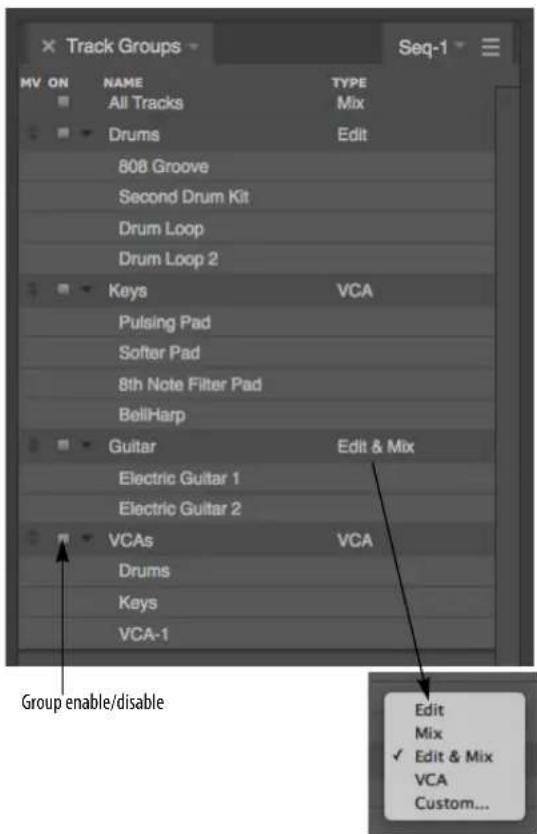
Figure 21-3: Track Groups window.
Use the Track Groups window as follows to manage track groups:
| To do this: | Do this: |
| To rename a track group | Double-click or Option/Alt-click its name. |
| To delete a track group | Click it to highlight it and choose Delete Track Group from the mini-menu. |
| To view the tracks in a group | Click its disclosure triangle |
| To add a track to a group | Select the tracks (or make a selection in the tracks you wish to add), click the track group in the Track Groups window to highlight its name, and then choose Add Selection to Group from the mini-menu. |
| To add a grouped track to another group | Temporarily disable track grouping (see “Temporarily suspending track groups” on page 190) and then use the procedure above. |
| To remove a track from a group | Click it to highlight it and choose Remove Tracks from Group in the mini-menu. |
| To temporarily disable or click the box to the left of its name. enable a group | |
To change the group typeChoose it from the 'Type menu as shown in Figure 21-3.
Group types
Track grouping allows you to apply operations to the tracks in the group as a single unit. For example, for a mix group, moving the volume fader for one track in the group moves the faders in all tracks in the group. The Group Type menu (Figure 21-3) lets you determine which operations are affected by the group:
Mix group
A Mix group controls track volume, play-enable (mute/unmute), solo, solo exempt status, automation play-enable, automation record-enable and automation mode.
If tracks are grouped for mix volume, dragging any fader within the group moves all members of the group, scaling them proportionally to their current values. Option/Alt-dragging temporarily overrides the group to adjust a control relative to the group.
You can override the grouping for volume and pan in the Mixing Board by holding down the Option/Alt key while dragging the fader or pan pot.
Edit group
An Edit group controls time range selections. If you make a time range selection in one track, all other tracks in the group are included. It also includes inserting, reshaping and dragging continuous data, as well as the following track display characteristics in the Sequence Editor: edit layer, continuous data mode, track size and vertical zoom size.
Mix & Edit group
A Mix & Edit group controls both the Mix and Edit group operations described above.
VCA group
Use the VCA group setting when you wish to control the volume of the tracks in the group with a VCA track, but you don't want (or need) any Edit, Mix or Custom group parameters for the group. With VCA volume control, the VCA track controls all of the individual track faders, but dragging an individual track fader only controls that fader, not the rest of the group, as it does for a Mix group. In addition, the VCA track controls the Solo, Mute, and Record Enable settings for the VCA group. Mix automation data, if any, is also affected. For more information about VCA tracks, including how to assign a VCA track to a group, see chapter 19, "VCA Tracks" (page 163).
Custom group
A Custom edit group lets you control a customized set of operations that you specify in the Custom group dialog (Figure 21-4). Check the items you wish to control in the group. If you choose Edit, Mix, Edit & Mix or VCA from the menu at the top
of the window, the check boxes in the window will update to show you what the default settings are for these preset groups.
If the custom group is being controlled by a VCA track, the Volume Fader option will be grayed out to indicate that volume faders are solely under the control of the VCA track (not individual track faders within the group).
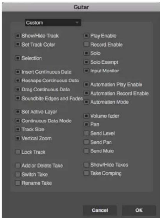
Figure 21-4: Customizing a track group.
Including a track in several different groups
Tracks can be a member of more than one group. If a track is already in a group, you can easily add it to another group as follows:
1 Select the tracks or make a selection in the tracks you wish to add. If they are already in a group that is an Edit group, you'll need to temporarily suspend track grouping so that you can select the tracks independently of the rest of their current group.
2 Click the track group in the Track Groups window to highlight its name.
3 Choose Add Selection to Group from the mini-menu.
Nesting groups within each other
Because tracks can be part of other groups, this allows you to create any grouped configuration you need, including nested groups. For example, you might group your kick, snare and hi-hat tracks into a group called Drum Kit, which is part of a larger group called Percussion, which is part of yet another larger group called Rhythm Section, which might include bass guitar, rhythm guitar, organ, etc. In addition, the group type can be different at each level. For example, the Rhythm Section group in our example might be for mixing only, whereas the Percussion and Drum Kit groups might be mixing and editing.
Temporary track groups
To temporarily group any currently selected tracks (that aren't already members of an active group), hold down the T key. Or double-tap the T key to make the temporary group "stick" until you tap or tap the T key again.
You can temporarily group all currently visible tracks in the Sequence Editor (or other multitrack editor) using the W key in the same fashion as described above.
Temporarily suspending track groups
To temporarily suspend a track group, press Command-Option-G (Mac) or Ctrl-Alt-G (Windows). Then type in the number of the group (in the order in which it appears in the Track Group window list). Or click the box next to its name in the Track Groups window. The track group name is displayed in italic text when it is temporarily suspended.
To temporarily suspend track groups globally, choose Project menu>Modify Track Groups>Suspend Track Grouping, or press Command-Option-Control-G (Mac) or Ctrl-Alt-G (Windows). To do so even more temporarily, hold down the G key. Doing so temporarily toggles the current suspension state.
Temporarily overriding the group on the fly
To temporarily override a group when moving a fader, Option/Alt-drag it. This allows you to adjust a track's level relative to the rest of the group.
Deleting tracks that belong to a track group
If you delete one or more tracks that are the sole remaining tracks in a track group, the track group is also discarded.
Track group keyboard shortcuts
Track grouping has its own set of fully customizable keyboard shortcuts in the Commands window (Setup menu):
| Command | Default keyboard shortcut |
| New Track Group Command/Ctrl-Shift-G | |
| Ungroup Tracks Command-Control-GCtrl-Win-G | |
| Temporarily Group Selection | T |
| Temporarily Group Visible Tracks | W |
| Track Group Enable... Command-Option-GCtrl-Alt-G | |
| Suspend Track Grouping Command-Option-Control-GCtrl-Alt-Win-G | |
| Temporarily Toggle Track Grouping | G |
| Add Selection to Group none | |
| Remove Tracks from Group none | |
| Delete Track Group none | |
| Set Temporary Group Type to Edit | none |
| Set Temporary Group Type to Mix | none |
| Set Temporary Group Type to Edit & Mix | none |
| Set Temporary Group Type to Custom Type | none |
Part 4
Playing and
Recording
CHAPTER 22 Control Panel
OVERVIEW
Digital Performer's Control Panel contains all the functions that make Digital Performer “go”: buttons to record, play, rewind, set tempo, and more. The Transport controls look and act just like the transport controls for a standard recorder. Additional buttons provide immediate access to many of Digital Performer's significant features.
The Control Panel appears across the top of the Consolidated Window. If it is popped out as a separate window, you can bring it to the front by choosing Control Panel from the Studio menu.
Quick Reference....196
Control Panel preferences....198
Transport Controls....199
Counter....201
Large Counter....205
Memory buttons....206
Auto-Record 210
Overdub record mode....211
Countoff....212
Wait....212
Slave to External Sync....212
Saving Memory and Auto-Record Times....212
Status Strip 213
Tempo Controls 213
Click 217
Audible Mode....217
Auto Scroll....217
Solo Mode 217
Primary and alternate tools 217
Keypad shortcuts 218
Display Preferences 219
QUICK REFERENCE
Transport Controls: These are Digital Performer's main controls for playback, recording, etc.
Main Counter: Displays the current playback position in one of Digital Performer's four time formats: measures|beats|ticks, real time, SMPTE time, or samples. Use the time format menu to the right to cycle through the four formats. Click the numbers and type to change the playback location. For more information about editing times in the Main Counter, see "Main counter shortcuts" on page 72 in the DP4 Getting Started Guide.
Aux Counter: Displays the current playback position in an alternative time format.
Counter settings: Independently for each counter, choose from the time display formats: measures|beats|ticks, real time, SMPTE time, samples, or markers.
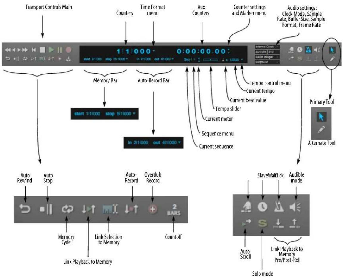
flowchart
graph TD
A["Transport Controls Main"] --> B["Counters"]
B --> C["Time Format menu"]
C --> D["Aux Counters"]
D --> E["Counter settings and Marker menu"]
E --> F["Audio settings: Clock Mode, Sample Rate, Buffer Size, Sample Format, Frame Rate"]
F --> G["Primary Tool"]
G --> H["Alternate Tool"]
H --> I["SlaveWaitClick"]
I --> J["Solo mode"]
J --> K["Link Playback to Memory Pre/Post-Roll"]
K --> L["Auto Scroll"]
L --> M["SlaveScroll"]
M --> N["Audio mode"]
N --> O["Auto Rewind"]
O --> P["Auto Stop"]
P --> Q["Auto-Record"]
Q --> R["Overdub Record"]
R --> S["In 211000 out 411000"]
S --> T["Memory Cyde"]
T --> U["Link Selection to Memory"]
U --> V["Countoff"]
V --> W["Link Playback to Memory"]
W --> X["Auto Rewind"]
X --> Y["Auto Stop"]
Figure 22-1: Digital Performer's Control Panel.
Marker menu: Lets you jump to any marker, or other significant points in the sequence, such as the Memory Cycle points or the Auto-Record punch-in location.
Main/Alternate Tool: Click to choose the desired main and alternate tool for the cursor. To temporarily switch to the alternate tool, hold down the semicolon key.
Auto-Rewind button: Causes automatic rewinding to the Memory Start location any time playback is stopped (for any reason).
Auto-Stop button: Causes playback or recording to automatically stop at the Stop location in the Memory Bar.
Memory Cycle button: Causes the time range between the Memory Start and Stop points to seamlessly repeat. In the time ruler of Edit windows, repeat barlines appear in the time ruler to indicate the repeat points.
Link Playback to Memory: Causes playback to start at the Memory Start location and end at the Memory End location.
Link Selection to Memory: Causes the Memory Start and End locations to be set by the current time range selection.
Auto-Record button: Causes automatic punch in and punch out during recording at the start and end times specified in the Auto-Record Bar.
Overdub record button: Toggles overdub record mode, in which newly recorded MIDI notes merge with existing notes instead of replacing them, and newly recorded audio data is layered on top of existing data (without replacing it). If Memory Cycle is also enabled, Overdub causes a new take to be created for each record pass.
Countoff button: Causes a number of measures to countoff before playback or recording. The button denotes the number of measures, which can be set in the Countoff preferences by Option/Alt-clicking the button.
Wait button: Causes Digital Performer to wait for a keystroke (or any other MIDI event) from a MIDI or computer keyboard as a signal to start playing back or recording. Wait can also be used together with Countoff to create an indefinite countoff.
Slave to external sync: When engaged, Digital Performer will wait for external sync. Option/Alt-click to open the Receive Sync preferences to set sync options.
Memory Bar: Contains the locations for Memory functions.
Sequence Bar/Auto-Record Bar: Displays the name of the project, the name of the current chunk, and the Sequences menu, or if enabled, the Auto-Record punch-in and punch-out times.
Current Meter: Displays the meter at the current playback location. To change the meter, you must use the Conductor Track>Change Meter command in the Project menu or insert a Meter change event in the Conductor track.
Tempo Slider: Lets you control the tempo of the sequence. When the Tempo Control menu is set to Tempo Slider, drag the slider to change the tempo; when the Tempo Control menu is set to Conductor Track, the slider cannot be edited; and when the Tempo Control menu is set to Tap Pad, the slider is replaced with a tap pad.
Current Beat Value: Displays which note value gets the beat in the beats-per-minute tempo indicator. Click on it to change it.
Current Tempo: Displays the current tempo in beats per minute. Click on it and type in a new tempo or drag the Tempo Slider. If you work with film, you can use the Display Preferences in the Digital Performer menu (macOS) or Edit menu (Windows) to display tempos in frame-clicks.
Tempo Control menu: Selects the current source of the tempo from a menu. Tempo can be controlled from the Tempo Slider, the Conductor track, the Tap Pad, or remotely from a MIDI controller such as a mod wheel. Tempo control can be changed during playback.
Clock Mode: Provides quick access to the master clock source for your system.
Sample Rate: Lets you set the sample rate of your project.
Buffer Size: Controls the hardware buffer size, which affects latency. See “Audio monitoring latency” on page 242.
Sample Format: Lets you set the sample format of your project.
Frame rate: Sets the SMPTE frame rate for your project.
Click (metronome) button: Turns the audible metronome click on or off. Option/Alt-click to open the Click preferences.
Audible mode: Enables/disables Audible mode.
Auto Scroll: Enables/disables auto scrolling for the active window and all other Edit windows of the same type.
Solo Mode button: Engages and disengages solo mode, according to the solo setup options. Option/Alt-click to open the solo setup dialog,
which lets you partially solo other MIDI tracks, or solo the track for the front-most event list window. See “Partial-solo” on page 223.
Pre/Post Roll: Adds a “lead-in” and “lead-out” when using Link Playback to Memory. Available only when Link Playback to Memory is enabled.
CONTROL PANEL PREFERENCES
The Control Panel appears across the top of the Consolidated Window. Like other cells, it can be popped in or out (see “Popping windows in and out” on page 117). It is also highly configurable, allowing you to show and hide sections. A Compact Height option conserves even more screen space. To access these settings, visit the Control Panel preferences (Figure 7-8 on page 81), or right-click anywhere on its background (Figure 22-2 below). When displaying shortcuts and the tool bar, you can show/hide individual tools and shortcuts.
| Open Control Panel Preferences Open Tools Preferences Open Shortcuts Preferences |
| ✓ Dock in Consolidated Window Compact Height Keep Tool Palette Visible When Displaying Editor Tools |
| ✓ Transport Controls ✓ Memory and Countoff ✓ Main Counter ✓ Auxiliary Counter ✓ Memory Times ✓ Auto Record Times ✓ Sequence Tempo and Meter ✓ Project Settings ✓ Auxiliary Controls ✓ Editor Tools ✓ Shortcuts Buttons ✓ Audio Performance |
Figure 22-2: Right-click on the Control Panel background to configure its layout as desired.
TRANSPORT CONTROLS
The Transport Controls are the buttons that make Digital Performer “go”: with them you can record, play, rewind and more. The Transport Controls are enabled by clicking on them. When a button is enabled, it is highlighted and its function is active: the Record button records, the Pause button pauses, etc. Most buttons can be disabled by clicking a second time. To disable the Play and Record buttons, press the Stop button.
Think of Digital Performer's transport controls as similar to tape recorder or CD player transport controls. But Digital Performer's transport controls are more flexible than their hardware counterparts in that they are programmable via the Memory buttons (on the left of the window), utility buttons (on the right) and menu commands.
The Play button and playback
Clicking the Play button starts playback of the currently play-enabled sequence or song. Playback will begin from the current time specified in the Counter. Playback can be delayed by the Countoff button and held by the Pause and Wait buttons.

Figure 22-3: Digital Performer's play button.
The Play button turns green while the sequence is playing. It flashes when waiting for synchronization in the External Sync mode or when the wait button is on.
If you start playback in the middle of a sequence, and you do not hear exactly what you expect, check Digital Performer's event chasing settings. for details, see "Event Chasing" on page 224.
During playback, most Digital Performer features remain accessible, including the Save command and all editing commands. As a general rule, commands that cannot be used will either appear greyed out during playback or they will have no effect.
The Rewind button
Clicking on the Rewind button sets the current location to the start of the sequence. If Memory Cycle or Auto Stop are enabled, clicking on the Rewind button will rewind to the Memory Start location. Double-clicking the button will always rewind to the start of the sequence or song.

Figure 22-4: Digital Performer's Rewind button.
If the Rewind button is clicked during recording, the record button is turned off. The sequence rewinds normally.
For details about rewinding automatically, see "The Auto-Rewind button" on page 206.
The Stop button
Clicking on the Stop button stops playback and recording. It also turns off the Pause button. All notes sounding when the Stop button is clicked will cease (unlike pause). If the Auto-Rewind feature is on, Digital Performer will rewind to the Memory Start location when the Stop button is clicked.

Figure 22-5: Digital Performer's Stop button.
The Pause button
Clicking on the Pause button once turns it on; clicking on it a second time turns it off. The Pause button is highlighted when it is on.

Figure 22-6: Digital Performer's Pause button.
Turning on the Pause button during playback will cause playback to be suspended without turning any notes off. Turning it off will cause playback to resume.
If the Pause button is turned on before playback, playback will be suspended until the Pause button is turned off.
While the Pause button is on, you can use the Rewind button and Counter window to adjust the current playback location. You may also set times in the Edit, Memory, and Auto-Record bars.
The Record button and recording
Clicking on the Record button turns it on and begins recording in the currently play-enabled sequence from the current location in the counter. When it is on, the Record button is red and can be turned off by clicking on it again. This disables the record function while continuing playback. You can also turn on and off the record button during playback for manual punch-in and punch-out, as many times as you like. A more general way to think of the Record button is as an on/off toggle switch that you control manually.

Figure 22-7: Digital Performer's Record button.
At least one track must be record-enabled for recording occur. This is done by clicking on the record-enable button for the desired track (or tracks). Record-enabling a track makes it the destination for incoming recorded data.
If you engage recording without a record-enabled track, the record button flashes red to alert you that recording will not take place (because no track is record-enabled). If the record button is not flashing, this means that recording is successfully occurring, either in a record-enabled track or from triggered clips in the Clips window.
If the Auto-Record button is enabled, the Record button will flash red when enabled. It will then turn solid red when the Punch In location is reached. When the Punch Out location is reached, the Record button returns to "record-ready" mode.
If the Record button is flashing in "record-ready" mode due to Auto-Record, clicking on it will turn it off, canceling the punch-in.
When slaved to external sync, stopping or rewinding the master device will turn off the record button except in the case of Tap tempo sync, which requires that you click the Stop button.
Overdub Record
See "Overdub record mode" on page 211.
Clip Record
See "Clip Record mode" on page 297.
Undo Record
Recording can be undone at any time with Digital Performer's unlimited undo features. For details, see "Undo" on page 573.
Fast/Slow Forward & Rewind
These four buttons scan through your sequence – fast or slow, forward or backwards. The right set of arrows cues forward in time, the left set cues backwards. The inner arrows cue slowly, the outer ones cue faster. Use the Transport preferences to choose whether cuing occurs smoothly and continuously or in fixed increments of your choosing. For example, you could program the
slow forward/rewind buttons to cue by one measure and the fast forward/rewind buttons to cue by four measures. See “Fast Forward/Rewind buttons” on page 96.
When cuing continuously, the left arrows cause playback to pause while cueing backwards until the arrow is released. If used during recording, the Record button will be turned off before cueing.
COUNTER
The Counter displays the current playback position in the currently play-enabled Chunk (sequence or song), expressed in different forms: measure time (measure|beat|tick), real time (hours:minutes:seconds.hundredths), frame time (hours:minutes:seconds:frames), samples (digital audio samples), or markers (the most recent marker in the sequence). Two of these formats can be displayed at the same time: one as a main counter and the other as an auxiliary counter.
For information the marker counter, see “Marker counter” on page 202; the other time formats are explained in detail in chapter 8, “Time Formats and Display” (page 99).
Using the Counter to change the current playback location
The current playback location is the position where the Chunk will next play or record from. You can edit the counter fields to change the current location.
You can change the current location in the currently play-enabled Chunk (sequence or song) by editing the counter numbers. This can be done while the Chunk is stopped or playing. If you edit the counter while the Chunk is playing, it will continue to play while you enter the values and will cue to the new location after you confirm your edit. To edit the counter:
1 Click on the time value you wish to change.
The number field will highlight.
2 Enter the number you want.
You can only enter valid values (e.g. you can't enter 27 frames if you've chosen a 25-frame standard). Use the Tab key to move from one value field to the next. The decimal point on the keypad can also be used to cycle through fields. (On Windows, make sure the Num Lock key is engaged to use keypad shortcuts.) If you make a mistake in entering a value, press the delete key or click on the field again and re-enter the value.
3 Click outside the highlighted number field or hit the Return key.
Using the decimal key or Command/Ctrl-T to edit SMPTE main counter
The decimal key on the numeric keypad (with Num Lock engaged under Windows) will highlight the main counter, even if it is SMPTE time, real time or samples.
There is a shortcut for setting the measure time: using Command/Ctrl-T or the decimal point on the keypad will select the measure field and set the beat field to 1 and the tick field to 000. You may then enter the number of the measure you want to

Figure 22-8: Main and auxiliary counters
move to. As soon as you click outside the highlighted field or press the Return key, the specified value will be entered.
These keys will always edit the main counter, even when it is set to SMPTE time, real time or samples.
Setting the counter time format
To change which time format is shown in the Main or Auxiliary Counter, click the Time Format menu buttons to the right of each counter.

Figure 22-9: Use the Time Format menus to choose which of Digital Performer's various time formats you would like to display in the counter.
The counter displays dashes when no sequence or song is play-enabled in the file. To display numbers, play-enable a Chunk in the Chunks window.
During playback, the measure time counter is updated each time a metronome click would occur. If the click value is set to a half note in 4/4 time, only beats 1 and 3 will display in each measure. The click value can be set with the Change Meter command in the Conductor Track sub-menu in the Project menu.
Playback dashes
If you would like for the last field of the counter to be displayed as dashes, instead of numbers quickly rolling by, enable the “Playback Dashes” option. You can set this independently for each counter.
Round on Entry
By default, the "Round on Entry" option, found under the Time Format menu (Figure 22-9), is enabled and edits to larger time fields will clear smaller time fields. When the “Round on Entry” is disabled, smaller time fields are preserved when editing larger fields.
For example, locate to 3|2|017, then select the counter's measures field and drag it upward. With "Round on Entry" enabled, the counter value will become 4|1|000, 5|1|000, 6|1|000, etc.; with "Round on Entry" disabled, the counter value will become 4|2|017, 5|2|017, 6|2|017, etc.
Marker counter

The Markers time format displays the most recent marker in the sequence.
The Markers counter can also be used to move the main transport to a marker location. Clicking on the marker name makes the field editable and displays a menu; choose the highlighted marker by clicking on it, or by pressing the Return or Enter keys.

Figure 22-10: Selecting a marker from the Markers counter
You can also type in the text field. As you type, the drop-down menu will narrow the list to show only the markers containing the characters that you've
typed. In the example shown in Figure 22-10, typing "ver" would narrow the list to Verse 1 and Verse 2, while typing "2" would narrow the list to Verse 2. The Up Arrow and Down Arrow keys can be used to navigate the list.
Marker menu
The Marker menu, underneath the sub counter's time format menu, functions the same as the Marker menu in the Tracks window. For details, see "The Marker menu" on page 175.
Setting the start time
The start time of the sequence is what you see in the counter when you rewind to the very beginning. Normally, the default start time for a sequence or song is measure time 1|1|000, real time 0:00:00.00 and frame time 0:00:00:00.
You can, however, use the "Set Chunk Start Time" command under the Sequence menu in the Status Strip.
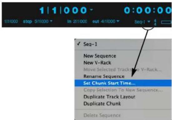
Figure 22-11: The Start Time button allows you to choose the start time at the beginning of the sequence for all of Digital Performer's time formats.
If you are synchronizing Digital Performer to SMPTE time code, you'll need to set the SMPTE start time according to SMPTE frame at which you want the Digital Performer to begin playing. For example, you may want the downbeat of the first measure in the sequence to begin playing when the time code reaches 1:00:20:00.
The following are other examples of situations in which you might want to change the sequence start time:
■ You would like to create one or more pickup measures before measure 1 (1|1|000).
- Your sequence should begin with a measure time other than measure 1 to match its location in a song. (For more information, see “Matching chunk start times with their location in a song” on page 817.)
The start times you enter for measure and real time are arbitrary and only affect the display of time locations. The SMPTE time code start time, however, determines the frame at which the sequence will actually begin playing while Digital Performer is slaved to external time code.
To set the start times of a sequence or song:
1 If you have more than one sequence or song in the file, make sure it is the currently play-enabled chunk.
To do so, look at the current chunk indicator in the Control Panel Status Strip (Figure 22-26 on page 213). If you need to switch sequences, choose the desired sequence from the Sequence menu in the Control Panel, or use the Skip buttons in the Chunks window.
2 Click the Sequence menu and choose "Set Chunk Start Time."
3 A dialog box appears. The current Chunk name is displayed near the top of the dialog box.

Figure 22-12: The Set Chunk Start dialog lets you choose completely different start times for each of Digital Performer's various time formats. This is where you determine the sequence's SMPTE start time (offset).
4 Click on the values you wish to change.
5 Enter the new values.
You may enter a value for each of the various time formats. Measure values range from -9999 to 9999. Real time ranges from 0:00.00 to 59:59.99. Frame time ranges from 0:00:00:00 to 23:59:59:30.
6 Click on OK to confirm your choice or Cancel to cancel it.
Using SMPTE timecode bits
In addition to the start frame, you may offset the SMPTE start time by a number of bits. There are 80 bits per frame. Although Digital Performer does not have single bit time resolution, it does offer sub-frame time resolution. Use the bit offset to finely adjust the start time.
Setting the SMPTE frame rate
The SMPTE frame rate can be set with Frame Rate command in the Setup menu.
Preserving locked markers when changing the start time
If your project contains locked markers, you can either preserve their location relative to the start of the sequence or preserve their absolute frame time when changing the sequence's SMPTE start time. For details, see “Locked markers and the sequence start time” on page 778.
Creating pickup measures before 1|1|000
Normally, when you rewind Digital Performer back to the beginning of the sequence, the measure counter reads 1|1|000. But sometimes you may have several pickup beats (or measures) in your music, and you may still want the music at measure 1 to remain at measure 1. If so, you can create as many pickup measures before 1|1|000 as you need.
To create a pickup measure:
1 As described in the previous section, set the measure start time of the sequence to 0 to create 1 pickup measure.
If you need two pickup measures, set the Measure start time to -1. If you need 4 measures, set it to -3.
2 Now, when you press Rewind back to the beginning of the sequence, the Counter window will read 0|1|000.
If you set up two or four pickup measures instead of only one, the counter would read -1|1|000 or -3|1|000 respectively.
3 If you already had data recorded in the sequence, shift the data back to its original location.
When you change the Measure start time, data that used to be at 1|1|000 is now at 0|1|000, and so on. All data has changed to match the new start
time. To restore all data to its original position before you changed the start time, use the Shift command to shift it back to where it was before.
4 Highlight all track names in the Tracks window and double-click the "Load Selection" button in the Selection Information window.
This selects the entire sequence.
5 Choose Shift from the Edit menu.
6 Choose the Later option and type in the number of pickup measures that you previously added.
If you added 1 pickup measure by setting the start time to 0|1|000, shift by 1 measure here.

7 Click OK.
You have now successfully restored all data back to its original location before changing the measure start time, and you also have several empty pickup measures in which to record.
The accuracy of the counter display Digital Performer's first priority is to keep up with the flow of MIDI and audio data. If DP encounters a great deal of data, it selectively ignores its graphic display until the processor load decreases. This may keep the counters from updating and they may skip beats during these times. This is
Digital Performer's way of keeping up, and does not necessarily mean that data is being transmitted inaccurately.
A side effect of this is that the counter may not always be accurate. It should therefore not be used as a metronome. In general, the counter display should not be used as a visual indication of tempo.
Controlling how often the counter updates During playback, the measure time counter is updated each time a metronome click would occur. For example, if the click value of the current meter in the sequence is set to a half note in 4/4 time, only beats 1 and 3 will display in each measure. The click value can be set with the Change Meter command in the Conductor Track sub-menu in the Project menu.
Negative numbers in the counter display When using an external sync source, Digital Performer may run for a little while before the sequence actually starts. During this time, you may see negative measure numbers. These increase in value (towards zero) until the start measure is reached.
LARGE COUNTER
The Counter window is identical to the main counter in the Control Panel, except that it is a large, separate window, and it can display all time formats at once.

Figure 22-13: The Counter provides a large display of any combination of time formats you choose.
Opening the Counter window
The Counter window can be selected from the Studio menu. Or, you may use its default key command, Shift-J.
Resizing the Counter window
The Counter window is freely resizable, and the text size scales along with the window size. At larger sizes, the Counter window is easily visible from across the studio or across the stage.
Setting the Counter window display
The counter window can display one or more of the four time formats in any combination. One format is designated as the Main Counter. It will appear at the top of the window. You can also specify three “Aux” (auxiliary) Counters which appear below the Main display. The format is identified by a small icon positioned just to the right of it. To set the counter display, choose the Set Display command from the Counter window mini-menu.

Figure 22-14: The Set Display mini-menu command lets you customize the Counter as desired.
Counter window mini-menu
In addition to the Set Display command mentioned in the previous section, the Counter window mini-menu also has a “Set Chunk Start Time” command. This functions the same as the Set Chunk Start Time” command under the Control Panel’s sequences menu.
For complete information about setting the start time of a sequence or song (chunk), see “Setting the start time” on page 203.
MEMORY BUTTONS
The Memory buttons (Auto-Rewind, Auto-Stop and Memory Cycle) allow you to automate the primary transport controls. By using the Memory buttons, you can program the transport controls to activate at times specified in the Status Strip.
The Auto-Stop button

Enabling the Auto-Stop button causes playback of the sequence to automatically stop at the Stop location
in the Memory Bar (Figure 22-1 on page 196). Clicking on the Auto-Stop button enables it; when enabled, it is highlighted.
When Auto-Stop is enabled, the Memory Cycle strip displays the start and stop times (Figure 22-16 on page 207), except that the green Memory bar displays the stop icon at its end point, as shown below, to indicate that playback will stop at the end of the green bar:

Figure 22-15: The Auto-Stop bar in the Memory Cycle strip.
The Memory Cycle button and the Auto-Stop button cannot be enabled at the same time.
The Auto-Rewind button

Enabling the Auto-Rewind button causes the sequence to automatically rewind to the Start location on the
Memory Bar. This occurs when the Stop button is pressed or when playback reaches the end position in the Memory Bar in Auto-Stop mode. Clicking on the Auto-Rewind button enables and highlights it.
Auto-Rewind is useful for returning to a particular location after stopping. It saves you from having to stop and rewind manually.
When Auto-Rewind is enabled, the Memory Cycle strip displays a green bar that begins at the Memory start time (Figure 22-16 on page 207) and extends indefinitely to the right, indicating that the transport will rewind to the start of the green bar from anywhere in the time line.
The Memory Cycle button

The Memory Cycle button is a cycle-playback and cycle-recording feature that causes a portion of the entire sequence to be played repeatedly until the stop button is pressed, just like drum machines and hardware sequencers. Cyclic playback begins when the sequence reaches the specified Memory Cycle time rage. When the Counter reaches the end of the cycle range, it seamlessly returns to the beginning and will continue to do so until you press the stop button, un-highlight the Memory Cycle button, or cue past the end time.
Use Memory Cycle for multiple consecutive playbacks of a particular time range. This can be very useful for cycle-recording a loop section or drum pattern, mixdowns, rehearsing a part that you plan to record, or for scrutinizing a particular section of a performance.
When cycle-recording, you add a new part to the loop with each consecutive pass. For MIDI tracks, be sure Digital Performer is in overdub record mode so that each new pass doesn't erase the last one. For audio, you can use Memory Cycle to overdub multiple audio passes into new takes. For details, see chapter 51, "Takes and Comping" (page 665).

Figure 22-16: Memory Cycle.
You can also cycle record into POLAR for multiple takes or layering. For details, see chapter 31, "POLAR" (page 299).
If you want to permanently loop a region in one or more tracks and specify the number of times the loop will repeat, create a clip. See “Loop Start time/End/Duration” on page 296 and “Looping a clip” on page 402.
Click on the Memory Cycle button to enable it. The next section discusses several ways to set the start and end times in the Memory Bar as shown in Figure 22-16.
The Memory Cycle button and the Auto-Stop button cannot be enabled at the same time.
Setting the Memory Cycle points graphically in the Memory Cycle strip
When Memory Cycle is enabled, the Memory Cycle Strip displays the Memory Cycle loop as a green bar (Figure 22-16 on page 207). This strip appears in the Sequence Editor, Tracks Overview, MIDI Editor and Drum Editor. Drag in the strip to enable Memory Cycle and set the start and end times. Drag the endpoints of the bar to change them, or drag the bar to move it. Click the bar to toggle Memory Cycle on or off.
If the edit resolution check box is checked, dragging gestures snap to the current resolution setting (such as 8th notes, for example). For an explanation of edit resolution, see “Snap to Grid” on page 355.
You can adjust the cycle points at any time, even during playback. This lets you build patterns and other tasks without ever having to stop the music.
Setting Memory Cycle points in the Memory Bar The Memory Cycle range is defined by the start and end times in the Memory Bar (Figure 22-1 on page 196). You can set these points in the Memory Bar by:
■ typing (use the Tab key as usual)
■ dragging on the numbers vertically
■ choosing the desired command from the Memory Bar menu
■ using several clicking shortcuts
■ using several keyboard shortcuts
- linking them to selection (as explained in “Link Memory to Selection” on page 210)
■ using the Remembered Times command
These same techniques are also used in the Selection Bar, and they are described in detail “The Track Overview” on page 181.
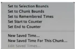
Figure 22-17: Setting Memory Cycle points with the shortcuts in the Memory Bar menu.
To automatically set the times to the current selection bounds, see “Link Memory to Selection” on page 210. To do so manually:
1 Set the Edit resolution in the time ruler.
If you want the end points to land directly on beat or measure boundaries, the easiest way to do so is to set the edit resolution to an appropriate value, such as eighth notes or quarter notes. If you want to be able to set the loop points with no constraints whatsoever, uncheck the edit resolution box.
2 Drag over the desired time range in any time ruler.
3 Highlight the Memory Cycle button if it is not already highlighted.
4 Choose "Set to Selection Bounds" from the Memory bar menu.
The time range is loaded into the Memory start and end times. In addition, the Memory Cycle repeat barlines appear in the time rulers at the beginning and end of the range you highlighted. Now Digital Performer will cycle between them during playback and recording.
Selecting the Memory Cycle range for editing If you would like to quickly select the time range within the Memory Cycle region, click either endpoint of the Memory Cycle bar (Figure 22-16 on page 207).
Link Playback to Memory

When enabled, the Link Playback to Memory button (Figure 22-1 on page 196) causes playback to begin and
end at the times prescribed in the Memory Bar (Figure 22-1 on page 196).
In addition, the playback wiper is only visible during playback, and the colored bar in the Memory Cycle Strip (Figure 38-1 on page 372) turns blue, instead of green, as shown below.

Figure 22-18: The colored bar in the Memory Cycle Strip changes from green to blue when Link Playback to Memory is enabled.
If Memory Cycle is also enabled (the third example shown above), playback will continuously loop within the Memory Cycle points.
Preroll and Postroll
When Link Playback to Memory is enabled, the Preroll and Postroll buttons become enabled (Figure 22-19). Click them to add preroll and postroll before and after the memory start and stop indicators. Preroll and postroll are displayed in time rulers as shown below in Figure 22-19. You can drag these indicators to change the amount of pre/postroll, or type in the desired amount in the text boxes in the Selection Information window (Figure 37-9 on page 360).
If Memory Cycle is enabled, there is no Postroll because playback never makes it past the end of the looped time range.

Pre- and Postroll buttons
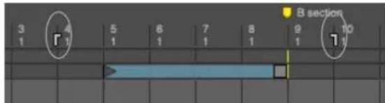
Figure 22-19: The Preroll and Postroll indicators.
The Preroll and Postroll text boxes (in the Selection Information window) adhere to the current global time format. This allows you to specify the amount of Preroll and Postroll in any time format you wish, including SMPTE frames, milliseconds, etc. For further information about time formats, see “Time Formats window” on page 100.
Punching in and out
If a track is record-enabled, and Auto-Record is disabled, the memory start and stop indicators serve as punch-in and punch-out points. If Auto-Record is enabled, then the Auto-Record Bar determines the punch-in and punch-out times.
Link Memory to Selection

When enabled, the Link Memory to Selection button (Figure 22-1 on page 196) causes the Memory Start and
Stop times to always match the current selection start and end times. By combining this mode with other memory modes, playback will always begin, end, and loop over the current selection. For example, if you enabled Memory Cycle, the memory cycle start and end times will always match the time range that is currently selected.
Linking playback to the current selection
By enabling both Link Playback to Memory and Link Memory to Selection, you essentially link playback to selection. In other words, playback will always begin and end at the start and stop of the current time range selection, with preroll and postroll, if any. If Memory Cycle is also enabled, playback will loop indefinitely within the current time range selection. In this mode, the current selection can be changed by editing the Memory Cycle points, and vice versa.
AUTO-RECORD
Auto-Record causes recording to automatically turn on and off in a specific time range. This allows you to record without having to manually enable and disable the Record button.

Figure 22-21: The Auto-Record button allows you to precisely program punch-in and punch-out points for recording.
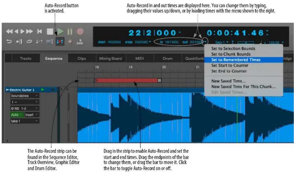
Figure 22-20: Punch-in and Punch-out points are depicted graphically as a red bar in the Auto-Record strip, which you can drag with Snap to Grid turned on or off.
Clicking on the Auto-Record button enables and highlights it. Clicking on the Auto-Record button also causes the Auto-Record punch in and punch out times to appear in the Status Strip (Figure 22-20 on page 210). Punch in and punch out times are specified in the Auto-Record Bar: Punch in is the time where recording begins; Punch out is where recording ends. Auto-Record can be used while Digital Performer is slaved to external sync; see chapter 86, "Receive Sync" (page 977) for details on recording while slaved to each type of sync.
The Auto-Record button will remain on until you click on it again to disable it. Remember to disable it when you finish using it.
Setting the punch-in and punch-out points graphically
When Auto-Record is enabled, the Auto-Record Strip (Figure 22-20 on page 210) displays the Auto Record region as a red bar. This strip appears in the Sequence Editor, Tracks Overview, MIDI Editor and Drum Editor. Drag in the strip to enable Auto-Record and set the start and end times. Drag the endpoints of the bar to change them, or drag the bar to move it. Click the bar to toggle Auto-Record on or off.
If the edit resolution check box is checked, dragging gestures snap to the current resolution setting (such as 8th notes, for example). For an explanation of edit resolution, see “Snap to Grid” on page 355.
You can adjust the Auto-Record bar at any time, even during playback or recording. This lets you adjust punch-in and punch-out on the fly without having to stop the music.
Setting the punch-in and punch-out points numerically
The Auto-Record time range is defined by the in and out times in the Auto-Record Bar below the main counter (Figure 22-20 on page 210). You can set these points numerically by:
■ typing (use the Tab key as usual)
■ dragging on the numbers vertically
■ choosing the desired command from the Auto-Record Bar menu
■ using several clicking shortcuts
■ using several keyboard shortcuts
■ using the Remembered Times command
These same techniques are also used in the Selection Bar, and they are described in detail "The Track Overview" on page 181.
OVERDUB RECORD MODE
If you click the Overdub button, Digital Performer goes into Overdub record mode. Overdub mode causes all recorded MIDI notes to merge with, instead of replace, pre-existing notes on the record-selected track. The pre-existing notes on the track are not erased. For audio data, new data is overlaid on top of existing data, rather than erasing and replacing existing data.

Figure 22-22: Digital Performer's Overdub Record mode button.
For MIDI tracks, the word overdub is used in a very specific sense in Digital Performer: real-time merging of incoming notes with note data already in a track. It works as if you recorded one track, recorded a second track to go along with it and then merged the two. You can use Overdub mode in conjunction with Memory Cycle to build patterns in multiple passes over a time range, similar to drum machines. (Overdub does not
affect the Conductor Track; specifically, recording on the Conductor Track while slaved to Tap tempo sync always erases existing tempo events.)
For further information, see “MIDI overdub recording” on page 248 and “Audio overdub recording” on page 248.
COUNTOFF
This buttons toggles the Countoff on and off. For more details on the Countoff and its options, see "Countoff" on page 259.
WAIT
Enabling the Wait button causes Digital Performer to wait until it receives a MIDI event before it begins to play back or record. The Transport preferences (on page 96) let you control what types of MIDI data the Wait button responds to.

Figure 22-23: The Wait button causes Digital Performer to wait for an incoming MIDI event before it begins to play or record.
To enable the Wait button, click on it; it will highlight. Then, press either the Record or Play buttons. The wait button will then begin to flash, signaling that it is waiting for a keystroke. To start playback or recording, press the enter key on the computer keyboard or your MIDI controller instrument. If recording is enabled, the MIDI event you send to turn off Wait will be recorded.
The Wait button will remain enabled until it is clicked off. Thus, it will be in effect every time the Record or Play button is clicked on.
Use Wait to give yourself a moment to ready yourself at your keyboard or other input instrument before recording. Using Countoff and Wait together allows you as much time as you need to prepare for recording.
If you turn on the Wait button together with the Countoff button, you create an indefinite countoff — the countoff keeps going until you start playing.
SLAVE TO EXTERNAL SYNC
When engaged, Digital Performer follows an external clock source, as specified in the Receive Sync command (Setup menu). Double click this button to open Receive Sync settings. For details, see chapter 86, “Receive Sync” (page 977).

Figure 22-24: The Slave to External Sync button.
SAVING MEMORY AND AUTO-RECORD TIMES
You can save Memory start/stop times and Auto-Record In/Out times using the commands in their menus, as shown in Figure 22-16 on page 207 and Figure 22-20 on page 210. Choose New Saved Time to name and save the currently loaded times, which will then appear in the menu as shown below:
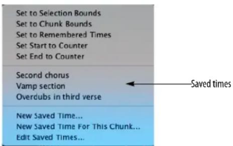
Figure 22-25: Saving a Memory start/stop or Auto-Record in/out time.
If you would like to save times that will appear in the menu only when the current chunk is play-enabled, use the New Saved Time for This Chunk command instead. Use the Edit Saved Times command to rename and delete saved times.
STATUS STRIP
The Status Strip has two sections that display information (Figure 22-26). The left side displays the Memory Bar, which contains the locations for Memory functions. The right side displays the name of the project and the sequence, or the Auto-Record punch-in and punch-out times, if enabled.
The Memory Bar
The Memory Bar displays the start and stop times for Auto-Stop, Auto-Rewind, and Memory Cycle.
For details about editing the start and end times in the Memory bar, see “Setting the Memory Cycle points graphically in the Memory Cycle strip” and “Setting Memory Cycle points in the Memory Bar” on page 208.
The Auto-Record Bar
The Auto-Record Bar displays the punch-in and punch-out times for Auto-Record. You can enter the start and end times numerically in the Auto-Record Bar. See “Setting the punch-in and punch-out points numerically” on page 211. You can also set them up graphically. See “Setting the punch-in and punch-out points graphically” on page 211.
The Remember Times command (control-R), allows you to save any time range selection, so that you can load it into the Auto-Record bar later on. You can also load remembered times into the Selection bar and the Memory Cycle bar. For complete information, see “The ‘Remember Times’ command” on page 556.
The Project and sequence info
The right half of the status strip (Figure 22-26) shows you the name of the currently play-enabled sequence or song. Just to the right of the sequence name is the Sequences menu, which lets you add, delete, rename and otherwise manage multiple sequences in your project. The Sequence menu also provides commands for creating, naming, and deleting sequences, as well as copying the current selection to its own, new sequence.
TEMPO CONTROLS
The Control Panel displays the tempo and meter of the currently play-enabled Chunk (sequence or song).

Figure 22-27: Digital Performer's Tempo Controls give you real time control of the tempo, as well as tempo programming (via the Conductor Track) and remote control of tempos from any MIDI source, such as the mod wheel on your controller keyboard.

The Tempo Control menu
Tempo can be controlled by one of five possible sources:
■ The Tempo slider
■ The Tap Pad
■ The Conductor track
■ By remote control from an external MIDI controller, such as a modulation wheel
■ The Tap to Enter Tempo command
The Tempo Control menu displays the current tempo source with a check mark; choose any other source from the menu to change it. You can change the tempo source at any time, even during playback, and the tempos you set in each mode are remembered. In addition, the tempo control settings are saved with each Chunk.
Tempo slid er
When the Tempo Control is set to Tempo Slider, you can change tempo by entering a value in the tempo box in the Metronome window or by dragging the slider with the mouse or by placing your mouse over the slider and using the mouse scroll wheel. Tempo is expressed in beats per minute (bpm). Any programmed tempo changes (the tempo map) are ignored. You control the tempo directly with the tempo box and slider. This mode is useful for Chunks with one constant tempo or for temporarily adjusting tempos when working on a Chunk.

Figure 22-28: when Tempo Control is set to 'Tempo Slider', use the slider, or just tap the back slash key () to enter a tempo value in the tempo box below the main counter. Press return to confirm the tempo.
The Tap Pad
When the Tempo Control is set to Tap Pad (Figure 22-29), the Tap Pad appears in place of the Tempo Slider:

Figure 22-29: Tap Pad tempo.
This mode is similar to Tempo Slider mode: the sequence plays at a global constant tempo. Use the Tap Pad (instead of the Tempo Slider) to establish the tempo. Click the Tap Pad repeatedly at the tempo you wish. You can also set the tempo by using the Tap to Enter Tempo feature (“Tap to Enter Tempo” on page 215). Or you can simply type it in as usual.
The Tap Pad is similar to the Tap to Enter Tempo command in regards to playback: it does not track your tapping while the sequence is playing. So you'll probably find it easier to use the Tap Pad when the sequence is stopped. If you would like Digital Performer to track your tapping during playback, use the Receive Sync Tap Tempo mode. For details, see "Tap Tempo" on page 983.
Conductor Track
When the Tempo Control is set to Conductor Track, you cannot use the tempo box or slider to set the tempo. Instead, the tempo map in the Conductor track takes control of the Chunk. In this mode, the tempo slider is merely an indicator of the current tempo; the plus/minus buttons become disabled and you cannot change the tempo or beat value directly
To hear tempo changes that you create with the Change Tempo command or by using Tap tempo sync, set the Tempo Control to Conductor Track, where programmed tempo changes and tempo maps are stored.
Remote control of the tempo
When the Tempo Control is set to Remote Control, the tempo slider can be controlled from an external MIDI source such as a modulation wheel on a MIDI keyboard, or any other source of continuous controller data.
To set up the Tempo slider for external MIDI control:
1 Choose Remote Control from the Tempo Control menu.
2 Choose Set Remote Source from the Tempo Control menu.
A dialog box appears.

Figure 22-30: The Set Remote Source feature allows you to control Digital Performer's tempo dynamically, during playback or recording, with an external MIDI source, such as the mod wheel on a keyboard.
3 Select the MIDI device from which the external control data will be received from the menu provided.
4 Select which type of MIDI data will be used to control the slider.
Modulation wheels send controller #1.
5 Click OK to confirm your choice or Cancel to withdraw the command.
Tap to Enter Tempo
The Tap to Enter Tempo command in the Commands window (Setup menu) allows you to tap a tempo setting from your computer keyboard (or a MIDI trigger event):

Figure 22-31: To locate and customize the Tap to Enter Tempo command, search on the word 'tap', and then enter the desired computer keyboard and/or MIDI event.
When the Project's Tempo control is set to Tempo slider (Figure 22-28 on page 214), you can change the tempo of the entire project (as displayed in the Control Panel) by simply tapping your customized keyboard shortcut or MIDI controller event for the Tap to Enter Tempo command. The BPM text box below the main counter will highlight to indicate that it is being modified by your taps. When you achieve the tempo you want, press the return key to confirm the change. If you attempt to do this while the sequence is playing back, Digital Performer will not closely track your tapping, like it does for the Tap Tempo Receive Sync mode (Setup menu), so you will probably find it most useful to use Tap to Enter Tempo while the sequence is stopped. If you would like Digital Performer to track your tapping during playback, use the Receive Sync Tap Tempo mode (see “Tap Tempo” on page 983).
Tapping to enter a tempo in a text box
The Tap to Enter Tempo command also allows you to tap a tempo setting into any text box where you can also type a tempo number (in beats per minute). For example, if you open the Change Tempo window (Project menu>Conductor Track), and you wish to enter a tempo in one of the text boxes in the dialog, instead of typing the number, simply click the text box (as if you were
going to type in a number) and then tap the Tap to Enter Tempo keyboard shortcut at the tempo you wish to enter. This allows you to specify the tempo by "feel", rather than by typing a number.
Use the Commands window to enter the desired keystroke shortcut for the Tap to Enter Tempo command. Search for the word "tap" in the commands window as shown in Figure 22-31. You can also assign a MIDI event from a drum pad or other MIDI source.
The Tap to Enter Tempo command shown in Figure 22-31 is not the same as the Tap Tempo feature (see “Tap Tempo” on page 983). The Tap Tempo command shown above is meant solely for entering a BPM value in tempo text boxes.
Canceling tempo entry
If you begin to tap in a tempo, but then change your mind, press the escape key (esc) to exit the tempo text box without making a change to it.
The current meter display
The meter at the current location is displayed for your reference. To change meter, you must use the Change Meter command in the Conductor Track sub-menu in the Project menu.
The beat value
The beat value is the note duration that “gets the beat” in a given meter. In 4/4, for example, the quarter note usually gets the beat: in this case, the beat value is a quarter note. In 6/8, the beat generally falls on the first and fourth eighth notes in the measure, thus the dotted quarter is the beat value.
The beat value you set does not necessarily correspond to the value you set for the metronome click. The metronome click value is set when specifying the meter with the Change Meter command in the Conductor Track sub-menu in the Project menu. For example, in 6/8 meter, you may set a tempo of an eighth note = 220, but, set the metronome click to a dotted quarter note (standard in 6/8 time). Quite often though, the beat value will be the same as the meter denominator (the lower number of the meter marking).
The current tempo
By default, tempos are displayed in beats per minute (bpm). The beat value can be any standard musical duration between a sixteenth and whole note. All beat values can be dotted. A dotted value is equivalent to one and a half times the value of the duration. (A dotted quarter note is equivalent to one and a half quarter notes, for example.) Tempos are displayed and entered with an accuracy of a hundredth of a beat per minute. This allows you to specify tempos with two numbers to the right of the decimal point, e.g. 104.78 beats per minute. In addition to providing you with a high degree of resolution, this also allows you to easily enter tempos that match standard frame click metronome values.
When the tempo slider is controlling tempo, you can enter the tempo directly into the current tempo box. To change the tempo, click the current tempo box to edit the tempo. If necessary, click the current beat value to change it.
Displaying and typing in frame-click tempos
If you write music for film, you might be accustomed to expressing tempos in frame-clicks as well as beats per minute.
In Digital Performer, you can type in tempos using either format. If you enter a frame click tempo, such as 12-6, Digital Performer will automatically convert it to beats per minute—at an extremely high degree of resolution (well beyond a hundredth of a bpm).

Figure 22-32: You can type in tempos in Digital Performer in frame clicks (using either a dash or a slash). Digital Performer will convert the click tempo to beats per minute at a very high degree of resolution. Use the Display Preferences in the Digital Performer menu (macOS) or Edit menu (Windows) if you want to see frame clicks all the time.
You can freely switch between the two formats. If you prefer to view frame-click tempos throughout Digital Performer, you can do so by setting the Data Display Preferences in the Digital Performer menu (macOS) or Edit menu (Windows) accordingly. See “Tempo Display” on page 81.
Tempo Control during external synchronization
When Digital Performer is slaved to external sync using the Standard MIDI beat clocks mode, the master device generates the tempo. The tempo slider acts solely as an indicator in this case: the master device (drum machine, a hardware sequencer, etc.) has complete control over Digital Performer's tempo, and the tempo control displays the phrase MIDI Sync to remind you that the Tempo slider is disabled because tempos are being generated externally by the master device:

Figure 22-33: When Digital Performer is slaved to external sync via MIDI Beat Clocks, the Tempo Control menu, slider handle and current tempo settings are temporarily hidden to indicate that tempo is being controlled by the incoming MIDI sync data.
When synchronizing to time code (such as SMPTE) using the Indirect or Direct lock modes, Digital Performer follows its own internal tempo. Set the desired tempo in the normal fashion, or set the Tempo Control menu to Conductor track to use a tempo map you have programmed into the Conductor track.
When synchronizing to Tap tempo sync, you control the tempo in real time by tapping (sending a MIDI event to Digital Performer), using any MIDI controller. For details on creating a tempo map using Tap tempo sync, refer to the chapter Receive Sync. When you choose Tap tempo and check the Slave to external sync command in the Setup menu, the Tempo slider is disabled and it reminds you why:

Figure 22-34: When Digital Performer is slaved to external sync via Tap Tempo, the Tempo Control menu, slider handle and current tempo settings are temporarily hidden to indicate that tempo is being controlled by the incoming Tap Tempo events.
Digital Performer automatically adjusts real time and frame locations when the current tempo is changed.
CLICK
This buttons toggles the Click on and off. For more details on the Click and its options, see "Click" on page 255.
AUDIBLE MODE
When engaged, Audible Mode allows you to listen to notes and soundbites one at a time as you highlight them. For details, see “Audible mode” on page 337.
AUTO SCROLL
Auto Scroll controls if and how windows will scroll during playback, recording, and cuing. For details, see "Auto scroll" on page 226.
SOLO MODE
This button toggles Solo Mode on and off. For more details on Solo Mode, see "Soloing Tracks" on page 223.
PRIMARY AND ALTERNATE TOOLS
Choose the desired tool from Primary Tool menu (Figure 22-1 on page 196). The cursor will then switch to the primary tool when you hover over an edit window, or any location where the tool applies.
The Alternate Tool (Figure 22-1 on page 196) serves as a temporary alternative to the primary tool. To temporarily switch to the alternate tool, hold down the 'x' key. This keyboard shortcut allows you to quickly switch between the main and alternate tool, without having to visit the Tool palette (Figure 36-1 on page 347). This keyboard shortcut can be changed in the Commands window (page 105): search for the Alternate Tool shortcut.
Displaying the full tool palette
As an alternative to displaying the primary and alternate tools, you can instead choose to show the full tool palette by enabling the Keep tool Palette Visible When Displaying Editor Tools preference (Figure 7-8 on page 81). When enabled, this preference causes the entire tool palette to be displayed in the Control Panel, as shown in Figure 22-35:

natural_image
Collection of gray tool icons including selection, drawing, and editing tools (no text or labels)Figure 22-35: The Tool Palette.
When the full tool palette is displayed, it always shows either the primary tool or the alternate tool, when you are holding down the 'x' key (or custom assigned key). To change the primary tool, click the desired tool. To change the alternate tool, hold down the 'x' key and while doing so, choose the desired tool.
KEYPAD SHORTCUTS
The Control Panel functions can be operated from the numeric keypad on an extended keyboard.

Figure 22-36: The extended keypad assignments for Digital Performer's Transport controls.
In addition, the spacebar acts as a play/stop toggle. These key assignments are provided for your convenience. However, you can create your own customized key assignments using the Commands window. See chapter 9, “Commands” (page 105) for more information.
DISPLAY PREFERENCES
The Control Panel can be configured to be a floating window so it always appears on top of other windows. Its transparency can also be set, from fully opaque to fully transparent. Both options can be enabled in the Control Panel preferences. For more information, refer to “Control Panel” on page 81.
CHAPTER 23 Playback
OVERVIEW
Except where noted, this chapter applies to both MIDI and audio track playback.
MIDI Playback basics .....221
Audio playback basics....221
How to play a sequence or song .....221
Monitoring levels....222
Editing during playback....222
Screen re-display....222
Muting and unmuting tracks during playback .....223
Soloing Tracks....223
'Partial-solo'....223
Looping playback 224
Playing the current selection .....224
Event Chasing....224
Auto scroll....226
Scrubbing multiple MIDI tracks....229
Scrubbing and grid snapping....229
Scrubbing audio....229
Slow and fast forwarding....229
Stop Sounding MIDI Devices (Panic) .....229
MIDI PLAYBACK BASICS
When Digital Performer “plays” MIDI tracks, it is not playing audio of any kind. Instead, it is sending out performance information in the form of stored MIDI data to MIDI-equipped instruments. These instruments use the data as instructions for when to turn notes on and off, how loud to play them, and so on. Conceptually, Digital Performer is similar to a player piano which uses a set of recorded data (the piano roll) to control its “instrument” (the piano mechanism). The synthesizer, sound module, or virtual instrument produces the actual sound, and Digital Performer tells it when and how to do so.
AUDIO PLAYBACK BASICS
When Digital Performer plays audio tracks, it reads audio data from the hard disk and sends the digitally encoded audio signal to your audio hardware (the built-in speaker output of your computer or your MOTU audio interface, for example). The digital-to-analog (D-to-A) converters in the audio hardware then convert the digital audio signal into an analog one that plays from the speakers you have attached to the audio hardware. Because the audio data is stored on the hard disk, Digital Performer has random access to the audio and can cue virtually instantaneously to any location in the stream of audio. For more information about these basic hard disk recording concepts, see chapter 8, “Hard Disk Recording Concepts” (page 55) in the DP4 Getting Started Guide.
HOW TO PLAY A SEQUENCE OR SONG
To play a Digital Performer sequence or a song:
1 Open a Digital Performer project.
2 If the project contains more than one sequence or song, choose Chunks from the Project menu and play-enable the sequence or song that you wish to play back.
Only one sequence or song can play at a time.
3 Play-enable the tracks you wish to play back.
If you are playing a sequence, double-click its name to open its Tracks window and click the Play-enable button to the left of the track names you wish to hear. If the track is not play enabled, you will hear nothing from the track. If you are playing a song, play-enable the tracks in each sequence that the song contains.
4 For each MIDI track, choose a MIDI output destination and patch (sound) as explained in "Choosing a MIDI output destination" on page 140 and "Choosing a default patch (sound)" on page 143.
5 For each audio track, choose an audio output destination as explained in “Choosing an audio input and output” on page 149.
6 Set the location from which you want playback to begin.
There are many ways to cue Digital Performer. Here are just a few: to simply rewind to the beginning of the sequence, click the Rewind button. To choose a general location, click the "wiper" cursor at the desired playback location in any time ruler in any window.
7 Press the Play button or press the spacebar.
The sequence will begin to play. The Counter advances.
8 When finished playing back, press the Stop button, or press the spacebar again.
MONITORING LEVELS
Long throw metering is available in both the Mixing Board (“Level meters” on page 839) and the Meter Bridge (“Meter Bridge” on page 885).
EDITING DURING PLAYBACK
Many of Digital Performer's features, such as windows, dialog boxes, edit region selection, edit commands, and other features can be used during playback. For example, you can open another window or use the Transpose command while the music is playing back; you do not have to press the Stop button beforehand. As you listen to your music and find that you would like to make a change, don't reach for the Stop button. Just execute the command while the music is playing. Here are some examples of things you can do during playback:
■ Select a region for editing (in an Event List, Tracks Window, etc.)
■ Edit a region with the Edit or Region menu commands
■ Rearrange Chunks in the Song window
- Cut, copy, drag, Option/Alt-drag (copy), etc. notes and data in MIDI Editor and QuickScribe Editor
■ Choose a different output destination for a track
■ Add, delete, rename, or reposition a track
■ Access a mini-menu command
Some features, because of their nature, cannot be accessed during playback. These features are either greyed out (inaccessible) during playback or will have no effect unless you press the Stop button before using them.
SCREEN RE-DISPLAY
During playback, Digital Performer does its best to update items on the computer screen, such as the Counter and scrolling windows. However, audio recording and playback can often place a high demand on the computing power of the machine, and Digital Performer makes playback a much higher priority than refreshing the screen display. Therefore, you may find at times that Digital Performer must devote all of the computer's resources towards this end and thus may not be able to keep the screen display completely smooth and current. In addition, editing commands may sometimes take longer due to the amount of processor time required to deal playback. Rest assured, however, that your data is playing back accurately.
MUTING AND UNMUTING TRACKS DURING PLAYBACK
Both MIDI and audio tracks can be muted and unmuted during playback by using solo mode or by clicking their play-enable button in the Tracks window or Sequence Editor, or their mute button in the Mixing Board. You can also record the action of muting and unmuting tracks. For details, see chapter 71, "Mix Automation" (page 851).
When muting a track, the response is instantaneous.
SOLOING TRACKS
Soloing tracks allows you to isolate tracks for playback. This is a quick way to temporarily mute or unmute many tracks at once without having to click on the Play-Enable buttons of each. Think of soloing as a second, independent play-enable state for all tracks. Any combination of tracks can be play-enabled when solo is turned on — even tracks that have been muted when solo is off.
The color of the play-enable button tells you its play status:
■ Blue — means the track will play in the current mode (solo or not soloed)
■ Gray — means the track is muted and will not play
- Orange — means that the track is muted when soloing is on but play-enabled (blue) when soloing is turned off
Click a play-enable button to change its status at any time, regardless of whether solo is turned on or off.
Solo is turned on and off by pressing the Solo Mode button (labelled "S") in the Control Panel. Solo status can be changed during playback. You may mute and unmute tracks at any time during playback.
Both the soloed play state and the un-soloed play state are remembered until you change them, and both are also saved with the project.
If the Solo front-most edit window option is checked in the Solo Setup dialog (see “Partial-solo” below for details), individual tracks can be soloed when their edit window is open (Event List, MIDI Editing, QuickScribe Editor, etc.) by pressing the solo button in the Control Panel.
When tracks are muted during soloing, Digital Performer continues to process the MIDI and audio data contained in them. This allows tracks to be soloed and un-soloed during playback without pauses or glitching.
'PARTIAL-SOLO'
The solo button provides an additional capability: "partial solo mode". In this mode, MIDI tracks that are being muted are not muted all the way. Instead, their volume is brought down part way by reducing their note-on velocities by a percentage that you choose.
To enable partial-solo mode: Option/Alt-click the "S" Solo Mode button in the Control Panel.

Figure 23-1: The MIDI Solo Setup preference allows muted MIDI tracks to actually play softly at any percentage that you choose. It also lets you choose whether edit windows solo a MIDI or audio track when they are in front — or whether solo status in the Tracks window is maintained at all times.
Partial solo percentage
The value you choose is the percent that note velocities in each muted MIDI track will be reduced to when muted. (Velocities are not permanently changed; they are only modified temporarily during playback.)
The 'Solo front-most edit window' option
This option determines what is soloed when you are editing an audio or MIDI track in an edit window (i.e. an Event List, MIDI Editor, QuickScribe Editor, etc. is open and active). When this check box is checked, the track you are editing is soloed by itself. When this option is unchecked, which tracks are soloed is determined by the (soloed) play-enable buttons in the Track Overview and the solo buttons in the Mixing Board window.
Disabling 'Partial Solo' mode
To disable ‘partial-solo’ mode, Option/Alt-click the Solo Mode button and set the menu to “Off”.
LOOPING PLAYBACK
Playback of the entire sequence can be looped seamlessly between any two points. For information see “The Memory Cycle button” on page 207.
PLAYING THE CURRENT SELECTION
To audition the current selection, choose Audition Selection from the Region menu (or press Option/Alt-spacebar).
EVENT CHASING
Event chasing addresses a common difficulty in MIDI sequencing: Since MIDI data is transmitted serially (one event at a time), events that occur early in the sequence will not change the sound of a virtual instrument plug-in or MIDI sound module when playback is started from a point later in the sequence. For instance, if a program change event (patch change) occurs in the sequence at measure five and you begin playback at measure twenty, then the program change event will not be played and the synthesizer may produce the wrong sound (such as a trumpet sound instead of a bass sound).
Event chasing prevents such discrepancies: Whenever playback is stopped, Digital Performer searches backward through each MIDI track for the previous occurrence of each type of MIDI event that is enabled in the Event Chasing window. When playback starts again, it transmits those events, which updates the destination instrument plug-in or MIDI sound module to the expected settings. In the previous example, this would ensure that the synthesizer changes to the bass sound (according to the previous patch change event) when playback begins from measure twenty. Event chasing is also very useful for making sure that plug-ins and sound modules are updated to the correct settings for volume, pan, and other control change data (controller data).
Enabling event chasing
To enable event chasing, choose Event Chasing in the Setup menu. Event chasing can be enabled or disabled for different types of MIDI events independently of each other.

Figure 23-2: Event Chasing ensures that you get what you expect to hear from your MIDI tracks, no matter where you start playback in your sequence or song.
Enable the types of MIDI events that you want Digital Performer to chase. Click Set All to enable event chasing for all types. In some cases, you may not want certain types of MIDI events to be chased. For example, it may be useful to disable event chasing when transmitting MIDI to devices that use MIDI messages for non-musical purposes, such as lighting controllers or console automation systems.
Audio track, auxiliary track, and master fader track parameters are not included in the Event Chasing window because Digital Performer always chases mix automation events in those types of tracks.
Inserting initial events in MIDI tracks
Inserting initial MIDI events such as patch change and controller values at the beginning of each track in the sequence is a useful practice in MIDI sequencing. This ensures that you hear what you expect from your instrument plug-ins and MIDI sound modules regardless of the state in which they were left when you finished working on a different sequence or playing a different part of the current sequence. It is especially useful when event chasing is enabled because it ensures that there are events for Digital Performer to chase when playback is started before any notes are transmitted from a given track.
For example, you might use the same hardware sampler module for a drum kit patch in two different sequences. In one sequence, the drum kit part plays quietly because its controller 11 (expression) value is 20. In the second sequence, the drum kit plays louder because its controller 11 value is 100. When you stop the first sequence and begin playing back the second sequence, the sampler's volume will still be low before the higher controller 11 value is received. Combining event chasing and placing an initial controller 11 event with value 100 at the beginning of the drum kit track in the second sequence guarantees that the sampler will play at the intended volume.
The “Take Automation Snapshot” command button in the Region menu is a convenient way to insert controller events for controller 7 (volume) and controller 10 (pan). For details, see chapter, “Snapshot automation” (page 864).
Omitting initial controllers in MIDI tracks
If you don't insert initial controller events at the beginning of a track, Digital Performer's event chasing feature transmits a default value when playback begins before the first event of a given type in a track (except for a few commonly used controllers discussed below). This only occurs for MIDI event types that are enabled in the Event Chasing window and are present somewhere in the track.
For example, the first pitch bend event in a track is in measure five and its value is -100. When event chasing is enabled for pitch bend and playback is started from measure one, Digital Performer will transmit a pitch bend event with value 0. When the wiper reaches measure five, a pitch bend event with value -100 will be transmitted as usual.
This behavior is usually desirable for tracks that are transmitting MIDI data to musical devices like virtual instrument plug-ins, synthesizers, and samplers. It may not be useful for devices that use MIDI messages for non-musical purposes, such as lighting controllers or console automation systems.
Forward chasing
If event chasing is enabled for controllers, the following commonly used controller types actually chase forward if there is no initial even in the track: CCs 1, 7, 10, and 11. For example, if you have CC7 in the track and the playback wiper is before the first CC7 event in the track, Digital
Performer chases forward to the first event in the track to establish the current value, rather than using a default value of 127. This is similar to how DP's audio automation works.
Event chasing and audio track editing
When the Interpolate chased automation events when editing option is enabled (Figure 23-2 on page 224), copying audio track data selections will generate and place ramp-style automation events at the selection boundaries and include them when pasting, merging, splicing, or shifting the clipboard data. When cutting or erasing, interpolated automation events are left behind at the region boundaries.
By interpolating automation events at edit boundaries in this fashion, surrounding automation curves are preserved.
In addition, DP interpolates automation events at the paste/merge/splice/shift destination boundaries to preserve automation values within the originally selected data region.
Event chasing in songs
Event chasing also works for sequences that are played inside a song chunk. In the example below, when playback begins at measure twelve (in the middle of Seq-2), the events in the tracks in Seq-2 will be chased as if Seq-2 were played by itself (not in the song chunk).

Figure 23-3: Sequences do event chasing, even when they are playing back inside a song.
AUTO SCROLL
Auto Scroll (View menu > Scroll) lets you control if and how windows will scroll during playback, recording, and cuing. You can choose whether all windows on the screen will scroll, or only the top window. In addition, you can choose what kinds of Digital Performer windows will scroll, and which ones will not. You can also choose to display or not display the scrolling wiper in any window. Finally, you can choose between “paging” or “continuous scrolling”.
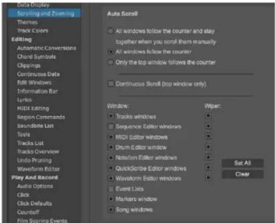
Figure 23-4: The Auto Scroll command allows you to configure how Digital Performer windows scroll during recording, playback and cueing.
All windows versus the top window
Choose Only the top window follows the counter to improve scrolling performance in the top-most (active) window when you have more than one window open on the screen. This option reduces Digital Performer's processing load. If you have a slow computer, or if your sequences tend to contain large amounts of dense MIDI data, this option will ensure responsive scrolling and smooth screen redisplay.
When you choose either of the All windows follow the counter options, all windows will scroll together during playback or recording, and they will even stay together when you cue Digital Performer when it is stopped. For example, if Digital Performer is stopped and you press Rewind, all Auto Scrolling windows will scroll to the new location indicated in the counter. Auto Scrolling occurs when pressing the cueing
buttons, typing a new location into the Counter window, cueing to a marker in the Markers window, or any other cueing method.
If you also want all windows to scroll together when you scroll one of them manually (with their horizontal scroll bar), choose the top-most option:
All Windows follow the counter and stay together when you scroll them manually.
Paging versus continuous scrolling
Digital Performer provides two types of window scrolling:
■ Paging
■ Continuous scrolling
Paging
When the Continuous Scroll option is unchecked, all Digital Performer windows proceed one windowful at a time during playback. That is, when playback reaches the last measure or event in the current time range being displayed in the window, the window jumps to the next windowful of data, just like clicking in the grey area of a scroll bar.
Continuous Scroll
When the Continuous Scroll option is checked, the contents of the top-most window scroll smoothly from right to left, with the current playback location centered (left to right) in the window. If the wiper is being displayed in the window, the wiper remains centered in the middle of the window, except when it is close enough to the beginning of the sequence that it must first travel from the left-hand side of the window to the center.
Initially, the playback position is centered (left to right) in the window. You can change it to show more of the sequence before or after the current position by Option/Alt-dragging the wiper.
Because continuous scrolling requires a great deal more of the computer's processing resources, it only applies to the top-most (active) window.
Continuous Scroll is available in the Sequence Editor, MIDI Editor and Drum Editor windows.
Enabling Auto Scroll by window type
The Window section of the Auto Scroll dialog lets you enable and disable auto scrolling by window type. Just check the boxes for the types of windows you wish to auto scroll. You can also enable and disable Auto Scroll by window type using the Auto Scroll button in the Control Panel when each window is the active window.

Figure 23-5: Enabling and disabling Auto Scroll by window type using the Auto Scroll button in the Control Panel.
Displaying the playback wiper
To display a scrolling cursor, or "wiper", check the Cursor check box in the Auto Scroll window for each window in which you'd like to see it.
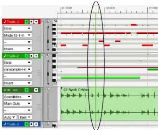
Figure 23-6: If you check the Wiper option for a window, a "wiper" appears to show the currently playback location of the sequence. This wiper can be dragged to change the playback location. You can also double-click inside the time ruler at any location to make the cursor jump to that location.
Cueing with the wiper
There are several ways to cue the current playback location with the wiper, either when Digital Performer is stopped or playing:
■ Double-click any time ruler at the desired location
- Click once in the upper half of the time ruler with the "wiper" cursor
■ Drag the wiper tab in the time ruler
Zooming with the wiper
You can zoom in and out by Control/Win- dragging vertically on the playback wiper handle. Control/Win-drag down to zoom in; drag up to zoom out. Release the Control/Win key to temporarily suspend wiper zooming. This allows you to continue zooming, even after you've reached the top or bottom of the computer screen. For example, if you pull down to zoom in, and you want to zoom in further but you're getting close to the bottom of the screen, release control, move back up to the top of the wiper (doing so maintains the current zoom level), press control/ Win, and then pull down to continue zooming in further.
To move horizontally while zooming, simply release the Control/Win key temporarily while continuing your drag gesture. For example, you can drag left or right and then press Control/Win again to further zero in on a particular location.
Wiper zooming is an extremely useful zooming shortcut. It works particularly well when used hand in hand with the Zoom Back command (command-]).
Auto Scrolling with multiple sequences or songs
Auto Scrolling will only occur in windows related to the currently play-enabled Chunk. For example, if a Song window is open, it will not Auto Scroll unless the song is play-enabled in the Chunks window. Windows associated with Chunks inside the song will not scroll when the song is play-enabled. Only the Song window and its Markers window will scroll.
Suspending Auto Scrolling
You can temporarily suspend Auto Scrolling in any window by simply clicking in the window or by scrolling the window manually. The window will stop for a moment before it resumes Auto Scrolling. This lets you view or edit things quickly without having to stop playback. Auto scrolling resumes after you leave the window alone for about 5 seconds. You can manually resume auto scrolling for the active window by clicking the Auto Scroll button in the Control Panel.
When Auto Scroll is enabled, windows that contain time rulers open to the current playback location.
Disabling Auto Scrolling
To disable Auto Scrolling altogether, click the Clear button in the Auto Scroll preferences window.
SCRUBBING MULTIPLE MIDI TRACKS
Scrubbing refers to the act of controlling playback manually, forwards or backwards, by dragging the Digital Performer's current playback location left or right. Scrubbing allows you to play MIDI tracks forwards or backwards in non-real time, where you control the tempo by how quickly you drag. Scrubbing is great for zeroing in on wrong notes or other artifacts that you hear during playback.
Scrubbing only happens in Digital Performer when Audible mode is turned on. To turn on Audible Mode, click the button with the speaker icon in the Control Panel.
You can scrub playback by using any of the following techniques:
■ Drag the playback wiper
■ Drag the QuickScribe Editor playback wiper
■ Drag Movie Window slider
■ Press the fast forward/rewind buttons or slow forward/rewind buttons in the Control Panel
Scrubbing respects the solo states of tracks, and in general, plays the same tracks that you would hear if you pressed the play button. This can be used in conjunction with Partial Solo Mode to only scrub the Edit window you are currently viewing. See “Partial-solo” on page 223 for details.
Scrubbing always chases:
■ patch changes
■ notes
■ pitch bend
■ volume controllers
■ sustain pedal controllers
While scrubbing, however, only the following event types are played back:
■ notes
■ pitch bend
■ sustain pedal
SCRUBBING AND GRID SNAPPING
If Snap to Grid is enabled, the wiper snaps to the grid while scrubbing. To scrub smoothly, disable the grid. See “Snap Information” on page 355. When scrubbing in the Tracks Overview, you can disable snapping. See “Playback and Scrub Wiper” on page 94.
SCRUBBING AUDIO
You can scrub the audio in a soundbite in the Sequence Editor. For information, see “Scrubbing audio inside a popped-up soundbite” on page 397 and “Scrubbing” on page 536.
SLOW AND FAST FORWARDING
When the slow and fast forward transport buttons are programmed for continuous cuing (see the transport preferences on page 96), fast forward advances the counter at four times normal speed and skips audio like a CD player. Slow forward advances the counter at half speed and slows audio down without skipping.
STOP SOUNDING MIDI DEVICES (PANIC)
The Stop Sounding MIDI Notes command (Studio menu) is a MIDI “panic” command – it will send an “all notes off” message to all MIDI devices. This is helpful if there is a stuck note or a MIDI feedback loop.
CHAPTER 24 Recording
OVERVIEW
Except where noted, this chapter applies to both MIDI and audio track recording.
Digital Performer records very much like a multi-track tape deck: you connect inputs, specify tracks to record into and push the record button. Digital Performer, however, has a great deal more flexibility than a tape deck. There are many features you can use while recording that affect which types of data are recorded, control the time span in which recording takes place, manage multiple takes on the fly, automate loop-recording, and much more.
This chapter covers recording into MIDI tracks and audio disk tracks in real time. It also briefly discusses several other methods for recording (Step Record, POLAR loop recording, etc.) and provides references to other chapters that cover these topics in detail. They are mentioned here as a means of seeing how they relate to the recording process as a whole.
Choosing a sequence to record into 232
Setting tempo and meter 232
Recording to a click 232
Recording with a Countoff 232
Input Filter 233
Input Quantize....233
Non-destructive output quantize 234
Preparing a MIDI track for recording....235
Preparing an audio track for recording 236
MIDI input monitoring 238
Audio input monitoring 241
Using the wait and countoff features....244
Start recording 244
Stop recording 244
How audio is recorded on disk....245
Undo record 245
Recording stereo audio 245
Recording in surround 245
Recording several MIDI tracks in one pass .....245
Recording several audio tracks in one pass....246
Recording audio and MIDI at the same time .....246
Manual punch-in/punch-out on the fly 246
Automatic punch-in/punch-out 246
Punch Guard 248
Overdub recording....248
Recording multiple takes....249
Cycle-recording 249
Step Recording....252
Retrospective MIDI Record 252
Recording in External Sync....252
Sample Format....252
Getting an error message 253
CHOOSING A SEQUENCE TO RECORD INTO
If you have more than one sequence or song in the project, be sure to play-enable the one that you wish to record into. To do so, look at the current chunk indicator in the Control Panel.

Figure 24-1: The current sequence or song.
If you need to switch sequences, use the Sequences menu next to the current chunk name, or use the Chunks window. If the sequence is inside a song, open the song's window by double-clicking on the song, highlight the sequence, and choose Set Record Sequence from the Song window mini-menu.
SETTING TEMPO AND METER
If the material you are recording is musical in nature, then it is best to match it with the tempo and meter changes in the sequence, if any. Then it will be much easier to edit and mix the material musically with reference to measures and beats.
There are two ways to align live-recorded audio and MIDI data with the beats and barlines in Digital Performer:
■ Record to existing material (such as a drum loop) or to a click
■ Record freely into Digital Performer and align the beats and barlines afterwards by hand
Recording to existing material is self-explanatory. Recording to a click is covered in the next section. To record freely, there is no need to set tempos or meters before recording. Instead, you turn off the click and simply record. When you're done, you can align Digital Performer's beats and barlines with your recorded performance as explained in chapter 63, "Record Beats" (page 765) and chapter 62, "Adjust Beats" (page 761).
Setting the tempo
To set a constant tempo, choose Tempo Slider from the Tempo Control menu in the Control Panel and drag the tempo slider to the desired tempo. Using the tempo slider is handy for quickly setting a straight tempo. If your music involves a tempo map (a series of tempo changes, including, perhaps, ones that change smoothly over time), you may prefer to set these up before actually recording any MIDI data. See chapter 57, "Conductor Track" (page 733) and chapter 58, "Change Tempo" (page 741) for details.
Programming a meter map
A meter map is a series of meter changes. To set up a meter map before recording, see chapter 59, "Change Meter" (page 749).
Recording at a slower tempo
If the MIDI or audio material you are recording is particularly challenging for you to play, try setting the tempo slider to a slower tempo, perhaps 10 to 20 bpm slower than normal, and record at the slower tempo. Afterwards, you can return the tempo slider to the correct tempo. MIDI data will be scaled to the correct tempo automatically. Audio data can be scaled to match the correct tempo in one easy step. For details, see “Adjust Soundbites to Sequence Tempo” on page 677.
RECORDING TO A CLICK
Digital Performer lets you record to a click. To learn more about DP's advanced click settings, see "Click" on page 255.
RECORDING WITH A COUNTOFF
Digital Performer can help you start a recording pass with a programmable countoff. For further information, see “Countoff” on page 259.
INPUT FILTER
The Input Filter allows you to specify what types of MIDI data are recorded.
To open the Input Filter window, choose Input Filter from the Setup menu.

Figure 24-2: The Input Filter allows you to control what types of data Digital Performer will record.
Choose the types of data to be input by clicking on the corresponding check box(es).
Please note! The types of data you select will stay in effect until you change the filter setting. The Input Filter setting will affect all data recorded. Be especially careful when muting types of data that you normally don't filter. If you don't remember to turn them back on afterwards, you may lose valuable data in the future during recording.
Specifying controller numbers
The buttons under the Controllers check box in the Input Filter allow you to quickly choose which controller data to record. Click in the Controllers check box, click on the type of option you wish, and then enter the controller numbers if necessary.
All: Information from all controllers will be recorded.
All except: Information from all controllers except the controller numbers you enter will be recorded.
Only: Only information from the controller numbers you enter will be recorded.
To add and remove controller numbers in the list for the All except and Only options, use the Add and Remove buttons to the right of the list.
The 'Input from MMC Devices' option
This option, when checked, allows Digital Performer to record MIDI data from MIDI Machine Control devices (devices in your MIDI configuration that have the MIDI Machine property checked). For example, you may have an MMC device such as an automated mixer, and you may need to record data from it, such as mix automation data. Just keep in mind, however, that it may re-transmit MMC commands back to Digital Performer, which will appear in whatever track you are recording into — although you could avoid this by using Multi Record. If you don’t need to record MIDI from your MMC devices, you can save yourself the hassle of having to worry about recording unnecessary MMC commands by unchecking this option.
INPUT QUANTIZE
The Input Quantize feature quantizes notes during recording in the same fashion as a standard drum machine. Notes get quantized immediately as they are being received and appear quantized in the track afterwards. If you are loop recording, the notes will play back quantized the next time through the loop.
Opening the Input Quantize Window
To open the Input Quantize window, choose Input Quantize from the Studio menu:

This is a standard Digital Performer window that can be left open while you play back, record, edit, and use Digital Performer's other windows and features. This allows you to make changes to Input Quantize during recording.
Turning Input Quantize on and off
To turn on Input Quantize, check the Enable input quantization box. When Input Quantize is turned on, all incoming notes are quantized according to the options shown in the Input Quantize window. To turn off Input Quantize, simply uncheck the box.
Setting the Input Quantize options
Input Quantize offers the same type of quantization as the regular Quantize command in the Region menu. The only differences are that 1) the quantization occurs in real time as data is being recorded, and 2) the options for each type of input quantization are set in the Input Quantize
window rather than the Quantize window. But Input Quantize options behave the same way as their counterparts in the Region menu.
For more information about the Input Quantize options, see “Quantize” on page 603.
Changing options during recording
Any option in the Input Quantize window can be changed at any time, even during recording. For example, you can record several measures with quantization turned on and then turn it off on the fly as you record the next several measures. As another example, you might check the triplet check box while recording triplets and uncheck it as you switch back to straight time.
Retrospective MIDI Record
Input Quantize can be used effectively with Retrospective MIDI Record. See “Retrospective MIDI Record and Input Quantize” on page 285.
NON-DESTRUCTIVE OUTPUT QUANTIZE
As an alternative to input quantizing, you can instead apply non-destructive quantizing on MIDI track playback with the Quantize MIDI plug-in. This preserves the original performance you record in the track, while at the same time playing it back quantized. The advantage to this scenario is that you can remove the quantization at any time to return to the original performance in the track, if desired.
PREPARING A MIDI TRACK FOR RECORDING
To prepare a MIDI track for recording:
1 Record-enable the MIDI track.
This can be done in several different windows in Digital Performer. In the Tracks window, click the Record button next to the track (in the REC column). If the button is red, the track is record-enabled. In the Mixing Board, click the record button below the solo and mute buttons. In the Sequence Editor, click the record button next to the track name. In standard record mode, only one MIDI track can be record-enabled. In Multi Record mode, several MIDI tracks may be record-enabled (see “Recording several MIDI tracks in one pass” on page 245).
2 If you are using Multi Record (Studio menu) to record two or more MIDI tracks simultaneously, or if you need to specify a MIDI device and channel to record from (in order to exclude data received from other input sources at the time of recording), choose the input device and channel from the track's Input column in the Track List.
See “Choosing an input source” on page 140 for details.
3 Select the playback device for the track being recorded.
See “Choosing a MIDI output destination” on page 140 for details.
4 (Optional) Turn on MIDI Patch Thru (Studio menu) so that you'll record the track with the same sound as it will play back with.
Patch Thru echoes incoming data to the output destination device you've chosen for the track. This is essential when using a separate MIDI controller instrument: it allows you to hear what you are playing while it is being recorded. For details, see “MIDI input monitoring” on page 238.
5 (Optional) If you are using MIDI Patch Thru, choose the desired patch (sound) for the track from its Default Patch or Patch column in the Track List. For details, see “The patch list” on page 143 and “The current patch” on page 143.
6 (Optional) Set the Input Filter, if needed.
See "Input Filter" on page 233 for details.
7 (Optional) Set up Input Quantize or non-destructive output quantize, if desired.
See “Input Quantize” on page 233 and “Non-destructive output quantize” on page 234 for details.
8 (Optional) By default, recorded MIDI data is captured into a clip in the track. If you would prefer that it be recorded freely, not into a clip, disable the Record MIDI in Tracks as Clips preference (in MIDI Options, shown below).

Figure 24-3: The 'Record MIDI in Tracks as Clips' preference.
You are now ready to record MIDI.
PREPARING AN AUDIO TRACK FOR RECORDING
To prepare an audio track for recording:
1 Make sure that the audio hardware that you are using for recording is activated.
If you are using the MOTU Audio System, choose Setup menu> Configure Audio System>Configure Hardware Driver to activate the hardware driver. For details, see "Configuring the hardware driver" on page 27 in the DP4 Getting Started Guide.
2 Choose an audio input to record from.
This is the microphone input on your computer, a physical input jack (or pair of jacks) on your recording hardware, or a virtual input from a software synthesizer or sampler. You can also choose one of Digital Performer's internal virtual busses as the input. This means that you can record output from any other track—or combination of tracks—that are assigned to the bus you choose. In the Track List, choose the input by pressing on the input column next to the track as shown below in Figure 24-4. You can also choose the track input from the Mixing Board or Sequence Editor windows (from the menu next to or below the track name).
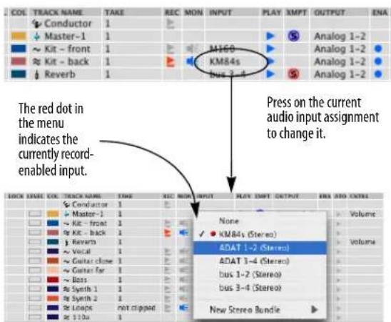
Figure 24-4: Choosing an audio input in the Track List. You can also choose an audio track input in the Mixing Board or Sequence Editor.
3 Record-enable the audio track.
This can be done in several different windows in Digital Performer. In the Tracks window, click the Record button next to the track (in the REC column). If the button is red, the track is record-enabled. In the Mixing Board, click the record button below the solo and mute buttons. In the Sequence Editor, click the record button next to the track name. More than one audio track can be record-enabled at a time. However, there is a preference (Digital Performer menu) that restricts record-enabling to one track at a time. For details, see “Audio Options” on page 94.
Record-enabling should be done before you actually begin recording; audio tracks can be record-enabled during playback or recording, but you may experience a brief pause. A better alternative is to punch in and out on the fly. See "Manual punch-in/punch-out on the fly" on page 246 and "Automatic punch-in/punch-out" on page 246 later in this chapter.
If the track's record button is missing, you need to choose an input first (Step 2 above).

Figure 24-5: Record-enabling an audio track.
4 In the Audio Monitor, confirm the current record input, as shown in Figure 24-6.
When you record-enable an audio track, the corresponding input row in the Audio Monitor turns red. In addition, the takefile name switches to plain text (instead of being italicized) as shown in Figure 24-6. Plain text indicates that the takefile has been created on disk and that the system is ready to record.
5 In the Audio Monitor, check for free hard disk space as shown in Figure 24-6.
The Audio Monitor displays free hard disk space in either minutes or megabytes (click to toggle the display as shown in Figure 24-6). One mono minute of audio at 44.1 kHz (CD quality) takes up approximately 5 megabytes of disk space. One stereo minute of audio takes up twice that (10 megabytes). (For other sampling rates, see “How much disk space does audio require?” on page 58 in the DP4 Getting Started Guide.) Plan your session accordingly. If necessary, you may need to back up and remove audio files left over from other projects from the hard drive. Or you may need to record onto a different hard drive than the currently selected one (see the next two sections).
It's a good idea to give yourself extra space (several hundred megabytes at least) because hard disk fragmentation is more likely to adversely affect audio recording when the hard disk is almost full.
If you are recording multiple tracks at once, and you are using the MOTU Audio System, you can record them on separate hard drives (as described in the next step).
If you anticipate creating audio files larger than 4 GB (about 6.7 hours when recording as 44.1 kHz 16 bit stereo interleaved files), use the Broadcast WAVE file format. For details, see "Wave64" on page 78.
6 In the Audio Monitor, check the location of the current takefile as shown in Figure 24-6.
When Digital Performer records audio, it places the audio data in an audio file on your hard disk with a name that matches the track being recorded into, followed by a dash and a take number. We refer to this destination audio file as a takefile. By default, takefiles are located in the same place on your hard disk as the last takefile recorded for that input. For new projects, takefiles are initially located in a folder called Audio Files, which is located in the project folder. (See “Components of a DP Project” on page 23.)
The current takefile location is displayed in the Audio Monitor as shown below in Figure 24-6.
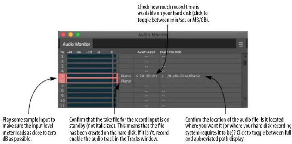
Figure 24-6: The Audio Monitor (Studio menu) is an important component of the audio recording process. Always check the settings shown above before recording. In this example, recording is being done on inputs 3-4.
If desired, you can change the current takefile location. For details, see “Changing the takefile location before recording” on page 267. You can also rename the current takefile. For details, see “Naming a takefile before recording” on page 267.
7 Check the audio input level.
Under MAS, check Retain Clip in the Audio Monitor mini-menu, play the input signal at its peak levels, and watch the level meter and adjust the input so that the peaks occur as close to 0 dB as possible without triggering the Clip indicator shown below.

Digital clipping is much harsher than analog clipping. Therefore, it's better to err on the low side. Use discretion.
You can also monitor input levels using the meters in the Mixing Board (chapter 70, “Mixing Board” (page 821)) or in the Meter Bridge (chapter 73, “Meter Bridge” (page 885).
MIDI INPUT MONITORING
MIDI Patch Thru (Studio menu) allows you to hear incoming MIDI data from your MIDI controller instrument played back on your output synthesizers (Figure 24-7) or virtual instruments. More technically, Patch Thru echoes MIDI data received by Digital Performer to any MIDI device in your studio that you choose. You'll want to use Patch Thru most of the time because it allows you to hear what you are playing on your MIDI sound modules while recording. Patch Thru also provides an easy way to experiment with different playback synthesizers without having to manually reconnect patch cords and change MIDI channels on the instruments.
Patch Thru works whether you are recording or not. However, MIDI data will only be patched through tracks which are record-enabled. If you don't hear anything on your synthesizer modules when playing your controller, check to be sure that the correct track or tracks are record-enabled.
Timing and synchronization data are not echoed in Patch Thru.

flowchart
graph TD
A["MIDI Cable"] --> B["Digital Performer"]
B --> C["MIDI Cable"]
C --> D["MIDI sound module"]
D --> E["Handheld keyboard"]
Figure 24-7: Here is an overview of how Patch Thru works. You press a key on your controller keyboard. The note gets sent to Digital Performer. Digital Performer determines which device (MIDI channel) the note will be echoed to by the track is currently record-enabled. It then sends the note to the output device assigned to that track, which plays the note using whatever sound (patch) is currently selected on that channel.
Turning on MIDI Patch Thru
To turn on MIDI Patch Thru, choose it from the Studio menu and select either Direct Echo or Auto Channelize:

Figure 24-8: Digital Performer's MIDI Patch Thru command offers two types of patch thru: Direct Echo and Auto Channelize.
Direct echo
Direct Echo causes incoming MIDI data from your controller to be echoed back out on the same channel it was received. For example, if your MIDI controller is transmitting on channel 3, MIDI data is echoed back out on channel 3 by Digital Performer. The Input Filter settings do not affect direct-echoed data; information is simply echoed straight through, bypassing most of Digital Performer's MIDI processing.
Direct Echo is useful in situations where you want to be able to change the channel you are echoing to from your MIDI controller keyboard by simply changing its transmit channel.
Auto channelize
Auto Channelize causes incoming MIDI data from your controller to be echoed to the output device and channel for the currently record-enabled MIDI track. The following sections discuss several scenarios that affect Auto Channelize.
Auto channelizing in a sequence
When a sequence is play-enabled in the Chunks window, here is how Auto Channelize Patch Thru works. In normal recording mode (Multi Record off), incoming data from any input source is echoed to the device specified for the record-enabled track in the currently play-enabled sequence.
Every time you change the record-enable track, Patch Thru repatches your controller instrument to echo out to the specified device for that track. Thus you always hear your incoming data as it would be played back.
If the record-enabled track is assigned to a MIDI device group (several playback devices at the same time), all of the devices will receive the patched thru data. (See “Creating a MIDI device group” on page 142.)
Auto channelizing with Multi Record turned on
If Multi Record is on (it's checked in the Studio menu), only MIDI data received on the specified recording Device for a track will be echoed to the corresponding playback channels for that track. In the following example, notes played on the K2600, channel 1 will be heard on MachFive, channel 2. Notes played from the ReMOTE controller, channel 2, will be patched through to the JV-1080, channel 1.
| Track-1 | 1 | ReMOTE-2 | JV-1080-1 | ||
| Track-2 | 1 | ReMOTE-1 | MX4-1-in | ||
| Track-3 | 1 | K2600-1 | MachFive2-1:A-2 | ||
| Track-4 | 1 | MIDI Keys-1 | MSI-1:A-1 |
Figure 24-9: In Multi Record mode, you can choose a specific source instrument (and channel, if desired) for each track that is record-enabled.
In the above example, the two controller instruments will be rechannelized separately. If two different tracks had the same input recording channel and had a common output channel, the incoming data will be echoed twice to that output channel. This may cause problems with some MIDI instruments; caution is advised.
Since Patch Thru works even when you're not recording, you can use Digital Performer as a sophisticated MIDI merger, mapper, or rechannelizer during playback, recording or when stopped. Patch Thru allows you to route MIDI information from your controller instrument to any combination of synthesizer modules. By adding a group of tracks, each assigned to a different MIDI channel or set of channels, you can change the module configuration used for playback by simply clicking on the record-enable button for the track or tracks with the desired channel configuration. This allows you to experiment with channelization freely.
Auto channelizing with MIDI effects plug-ins
The Mixing Board allows you to apply real-time MIDI effects plug-ins to a track. For example, you could apply the Echo effect to a MIDI track to make it echo during playback.
These same effects plug-ins will affect MIDI Patch Thru as well. When you record-enable a track, and the track has MIDI effects plug-ins currently applied to it, you will hear the effects on what you play.
This allows you to apply effects — in real time — to what you are recording into (and patching thru) Digital Performer. For example, you can apply a Transpose Map that constrains all notes to within a certain scale — which automatically cleans up any wrong notes that you play! Or you can apply a MIDI echo as you record. See “Working with effects plug-ins” on page 845 for details.
Auto channelizing in a song
If a song is play-enabled in the Chunks window instead of a sequence, the following two conditions are necessary for Auto Channelizing to occur: 1) a sequence within the song must be record-enabled, and 2) a track within that sequence must also be record-enabled. If both are true, then MIDI Patch Thru will operate in the same manner as described above. For information about record-enabling sequences in a song, see chapter 69, “Songs” (page 809).
Auto channelizing and the Input Filter
The Input Filter affects incoming data in MIDI Patch Thru mode. All data selected to be filtered out will not be echoed to the outputs. For example, if the pitch bend box is not checked in the Input Filter dialog box, pitch bend information will not be echoed through in MIDI Patch Thru.
Patching thru in the background
Digital Performer continues to patch thru even when it is in the background, i.e. not the active application. For example, if you bring another program to the front, you'll still be able to patch thru from your controller via Digital Performer.
MIDI beat clocks and MIDI Patch Thru
If you use MIDI Patch Thru with a drum machine or any device that outputs timing information, the timing information will not be echoed through. To echo timing information, see chapter 88, "Transmit Sync" (page 1001).
MIDI patch thru via a MIDI interface
Some MIDI interfaces, such as the MIDI Express XT, have a patch thru option built into them. If you choose to use the echo feature, turn off MIDI Patch Thru on Digital Performer or incoming data will be echoed twice. If you choose to use MIDI Patch Thru in Digital Performer, turn off the echo feature on the interface for the same reason.
Sync Recorded MIDI to Patch Thru
If you have a MOTU USB MIDI interface, Digital Performer records with an extra degree of precision. When you are recording with MIDI Patch Thru turned on, Digital Performer places the events in the track so that what you heard yourself play when recording is exactly what you'll hear when you play back your performance. To do
this, Digital Performer must compensate for the inherent, small amount of time it takes for the computer to receive the incoming MIDI data and send it back out to the patch thru destination. It does so by placing the event in the track a few milliseconds after the time at which it was actually received.
However, there may be times when you are not listening to your performance via Digital Performer's MIDI Patch Thru. For example, you might be playing your synthesizer with local control turned on, i.e. triggering sounds directly from its own keyboard. In this situation, be sure to turn MIDI Patch Thru off. Or, leave MIDI Patch Thru on and disable the Sync Recorded MIDI to Patch Thru option in the MIDI Patch Thru dialog (Studio menu) as shown below in Figure 24-8 on page 239. Doing so ensures that events are recorded exactly when they're received (as you heard when playing them).
Patch Thru in Background
The Patch Thru in Background option (Figure 24-8 on page 239), when checked, lets you continue to use Digital Performer's MIDI patch thru, even when DP is not the active application. For example, you could switch to the computer desktop and still continue to play a virtual instrument from your controller.
AUDIO INPUT MONITORING
Audio input monitoring is the process of listening to the live input signal being fed to a track via its chosen hardware input (Figure 24-4 on page 236). Digital Performer lets you do this by “patching thru” the input signal to the track’s output destination (see “Choosing an audio input and output” on page 149). So be sure to choose an output destination assignment that is patched to a listening device. For example, you might choose a pair of audio outputs on your audio interface that is connected to a set of speakers, or a pair of outputs that is patched to the headphone outs on your audio interface. The output assignment can also be a bus that is being routed via an aux track to your speakers.
The input monitor button
To monitor an audio track's input, click its input monitor button to enable it (make it turn blue). There are several ways to enable input monitoring, as summarized below:
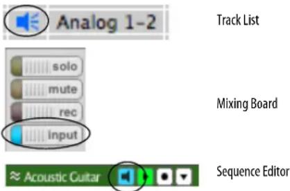
Figure 24-10: The input monitor button in the Track List, Mixing Board, and Sequence Editor.
If you don't see the Input Monitor button for a track, you need to choose an input for the track. See "Choosing an audio input and output" on page 149.
Input monitoring can be enabled or disabled independently of the track's record-enable state.
The record button
When you record-enable a track (Figure 24-5 on page 236), input monitoring is enabled and you will begin to hear the live signal being received on the track's chosen hardware input. This is true, regardless of whether or not the track's input monitor button is engaged.
If you don't hear live input when the track is record-enabled, audio patch thru might be turned off, as explained in the next section.
Input monitoring modes (Audio Patch Thru)
Digital Performer provides four input monitoring modes that govern when you hear live input and how the live input signal interacts with disk audio
(existing audio material in the track) during playback and Auto Record. In addition, input monitoring can be disabled entirely. To access these input monitoring modes, go to the Studio menu>Audio Patch Thru sub-menu:
Audio Patch Thru setting Explanation
| Off The track input is never audible, regardless of the input monitor or record button state. |
| Input Only When the track is either record-enabled or the input monitor button is enabled (or both), you hear the track input only, and you will not hear any disk audio during playback. |
| Auto Same as Input Only, except that during Auto Record, when you are playing but not yet punched in, you will still hear disk audio (until punch in occurs). |
| Blend When the track is either record-enabled or the input monitor button is enabled (or both), during playback, you hear both the input and the disk audio. |
Monitoring input levels
In addition to the level meters in the Input Monitor (Figure 24-6 on page 237), long throw metering is available in both the Mixing Board (“Level meters” on page 839) and the Meter Bridge (“Meter Bridge” on page 885). The Meter Bridge provides audio track input monitoring, whereas the Mixing Board provides both MIDI and audio track input monitoring.
Monitoring outside of Digital Performer
If you are using Digital Performer with an external mixer, or via the hardware-based CueMix DSP monitoring features in your MOTU audio interface, you might choose to monitor in the external hardware instead of through Digital Performer. In this scenario, or any situation in which you do not need to monitor the incoming audio via the outputs of the audio interface connected to your computer, disable Audio Patch Thru.
Applying real-time audio effects plug-ins to live audio input
You can apply effects plug-ins to the live input signal by adding effects plug-ins to the track in the Mixing Board. (See “Inserts” on page 827.) However, you should read the following sections first, which discuss several important issues surrounding audio input monitoring under the MOTU Audio System.
Audio monitoring latency
You might hear a slight delay when monitoring audio input. For example, if you have a sequence that already has several tracks of audio recorded, and you then try to record along with it while monitoring your input via Audio Patch Thru, you might hear a slight delay in what you are playing. This delay is commonly referred to as monitoring latency. Fortunately, however, the audio will be recorded into the sequence accurately and in sync with the other previously recorded audio tracks (as long as you managed to play it in sync with the sequence). But what you hear while you are recording will be noticeably and consistently behind. In other words, what you hear during recording will not be what you get: during recording, the input signal will sound late, but when you play it back after recording it, it will be fine (again, as long as you managed to play it in time with the sequence).
Again, audio is always recorded accurately. Latency is only an issue for monitoring (the live audio input that you listen to while recording).
There are several ways to minimize monitoring latency. Some of them are specific to certain hardware.
■ Monitor outside of Digital Performer entirely (with a mixing console, for example).
- Use your audio hardware's direct, hardware-based monitoring feature, if any.
- For MOTU audio hardware, set input monitoring mode to ‘Direct hardware play though’. You will not be able to monitor through audio effects plug-ins, but monitoring latency will be greatly reduced or completely eliminated. See “Hardware monitoring versus monitoring with effects” below for more information.
Hardware monitoring versus monitoring with effects
When you use your audio hardware's built-in "hardware-based" monitoring feature (if any), there is little or no audible delay. However, the trade-off is that the input signal is not routed through the MOTU Audio System. This means that if you have effects such as EQ or reverb assigned to the track that is currently record-enabled, you will not hear the effects applied to the input signal.
In summary, your two choices for monitoring input are: 1) delayed input with effects, or 2) dry input with no delay.
You also have a third option: turn off your audio hardware's "hardware-based" monitoring and lower the Buffer Size setting. The default settings is 1024 samples. Try lowering it to 512, 256 or even 128 samples. This gives you the best of both worlds: very low monitoring latency (3-6 ms) with effects processing. The trade-off in this scenario is that the lower buffer settings put more strain on your computer.
Setting the input monitoring mode
The two choices for input monitoring described in the previous section are provided by choosing Configure Audio System > Input Monitoring Mode from the Setup menu, which opens the dialog shown below in Figure 24-11.

Figure 24-11: Under the MOTU Audio System, Digital Performer provides two input monitoring modes. 'Direct hardware playthrough' provides monitoring without delays, but it does not provide effects on the monitored signal. 'Monitoring record-enabled tracks through effects' lets you monitor input with effects applied to it, but there could be a noticeable delay in the signal.
Direct hardware playthrough
Direct hardware playthrough provides accurate monitoring with no delays, but if you have real time effects (EQ, reverb, etc.) assigned to the track being recorded into, you will not hear them during monitoring. Effects will, however, be applied to the recorded material during subsequent playback.
When this option is chosen, the input signal currently being monitored can always be heard, i.e. it will be patched through when Digital Performer is stopped, playing or recording.
When operating Digital Performer with a MOTU audio hardware system, this option is required to enable the Cue Mix ™ monitoring feature.
Monitor record-enabled tracks through effects
Monitor record-enabled tracks through effects lets you apply effects to the input signal (via the effects inserts of the currently record-enabled track), but you might hear a delay during recording. If, however, the input signal is actually received by
the computer in sync with the rest of the sequence, the input signal with be recorded properly (with no delay).
When this option is chosen, the input signal currently being monitored can always be heard when Digital Performer is either stopped or recording. During playback, however, the input signal being monitored will never be summed with existing track contents. Instead, you will hear either one or the other.
USING THE WAIT AND COUNTOFF FEATURES
The Wait feature holds recording until you hit a key on your MIDI keyboard or the computer keyboard. Countoff gives you a number of measures of countoff in the starting tempo before recording begins. For details, see “Wait” on page 212, “Click” on page 255 and “Click Preferences” on page 256.
START RECORDING
After making the preparations already discussed in this chapter, you are ready to begin recording:
1 Set the Counter to the location in the sequence at which you want to begin recording.
If you are recording into a new sequence, you'll probably want to start at the beginning of the sequence. To do so, click the Rewind button. To start at a specific location other than the beginning, type in the location in the Counter.
2 To begin recording, press the Record button in the Control Panel.
The Record button will turn red, indicating that Digital Performer is recording in real-time. You can also trigger recording by pressing the [3] key on the numeric keypad (with Num Lock engaged under Windows) or, if you have already set up a MIDI remote control, by sending a MIDI event from your controller.
To achieve the fastest response possible when you begin recording, use pause-record. That is, press the pause button first and then record. Digital Performer allocates record buffers as needed and then waits for you to press pause again to begin recording.
Display update during recording
During recording, Digital Performer displays audio and MIDI data as it is being recorded. For audio, you'll see a continuously updating red bar. This bar appears temporarily during the record pass; it is for display purposes only and cannot be edited. However, as soon as recording stops, the bar is replaced by a fully editable soundbite.
Record-enabling audio tracks on the fly
You can record-enable (and disable) audio tracks while playing (but not while actually recording). In other words, you can toggle audio track record-enable buttons as long as the record button is not red or flashing red. Therefore, to change record-enabled audio tracks during a record pass, just press the record button to temporarily drop out of record, change audio track record-enables as desired, and then press record again to drop back into record. If you have already recorded some material, and you change record enables on the fly in this manner, the previous material is “put away” (the red, temporary waveform bars turn into normal, editable soundbites).
STOP RECORDING
To stop recording, stop Digital Performer by clicking the Stop button, pressing the spacebar, or pressing the [0] key on the numeric keypad (with Num Lock engaged under Windows).
Digital Performer stops recording and takes a moment to process the audio data.
For audio tracks, each record pass gets placed in the audio track as a single soundbite. The soundbite also gets added to the list in the
Soundbites window. You can view the soundbite by opening the Sequence Editor or Event List of the track.
HOW AUDIO IS RECORDED ON DISK
Digital Performer and other computer-based digital audio recording systems record audio data in much the same way. For a detailed explanation, see “How audio is recorded on disk” on page 55 in the DP4 Getting Started Guide.
UNDO RECORD
Immediately after you record (before you do anything else), you can undo what you just recorded. For audio tracks, Digital Performer moves the takefile into the trash. If you then do another undoable action, the takefile is remembered in the undo history. However, at the end of the session, when you close the project, Digital Performer will alert you that there are unused record takes and ask if you want to delete them. This lets you undo and redo as much as you want without worrying about your hard drive filling up with unwanted takes.
Stereo recording is done in the same fashion as already described in this chapter, except that you record into a stereo track instead of a mono track. To add a stereo track, choose Add track > Stereo Track from the Project menu. Then just record-enable the track and prepare for recording as usual.
■ If your project interleave format is interleaved, the stereo audio will be recorded to a single file.
- If your interleave format is deinterleaved, recorded audio data is stored as two separate mono files, each with the same name and .L or .R in the file names (e.g., “Guitar-1.L.wav” and “Guitar-1.R.wav”). The corresponding soundbites in the track will remain perfectly sample-locked, no matter what you do.
Recording in surround is handled as already described in this chapter, except that you record into a surround track. To add a surround track, choose Add Track from the Project menu and then choose the desired surround format from the submenu. Then just record-enable the track and prepare for recording as usual.
■ If your project interleave format is interleaved, the surround audio will be recorded to a single file.
■ If your interleave format is deinterleaved, recorded audio data is stored as separate mono files, each with the same name and the appropriate surround channel name in each file (.L, .C, .R, etc.). The corresponding channels in the surround track will remain perfectly sample-locked, no matter what you do
RECORDING SEVERAL MIDI TRACKS IN ONE PASS
Multi Record mode is used to record from several MIDI devices simultaneously; each channel may be recorded on a separate track. This is very useful in transferring data from another sequencer or when recording from several MIDI instruments simultaneously. Multi Record is also useful for recording MIDI data while slaved to Tap tempo. See “Tap Tempo” on page 983 for more information.
In addition to the steps listed in “Preparing a MIDI track for recording” on page 235 above, you need to do the following to prepare for recording in Multi Record mode:
1 Find out the current transmit channel on your MIDI controller keyboards or other input devices.
If you are recording from multiple MIDI sources, you may want to set each instrument or source sequencer track to transmit on a different channel. This helps avoid accidentally merging them.
2 Choose Multi Record from the Studio menu to check the menu item.
The INPUT column appears.
3 Record-enable the MIDI tracks that you wish to record on.
Click on the record-enable button next to the track. To toggle the record status of several tracks at one time, just drag — “glide” — over their record buttons. This is a great shortcut for toggling many tracks quickly.
4 Select the input device and channel for each track from the menus provided in the INPUT column.
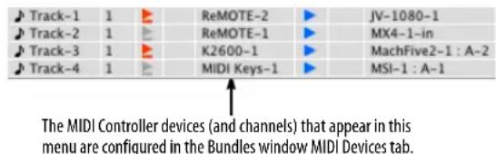
Figure 24-12: Selecting an input device for each MIDI track in Multi Record mode.
5 Get ready to record.
If you are sending data from another sequencer or a time-based MIDI device, you will probably want Digital Performer to synchronize with it. To put Digital Performer in External Sync mode, see chapter 86, "Receive Sync" (page 977).
Changing Multi Record on the fly
You can toggle Multi Record (Studio menu) during playback.
RECORDING SEVERAL AUDIO TRACKS IN ONE PASS
Digital Performer lets you record as many audio tracks at one time as your computer and audio hardware allow. Just record-enable the tracks as needed.
The total number of audio tracks you can record into at one time depends on your audio hardware.
RECORDING AUDIO AND MIDI AT THE SAME TIME
Digital Performer allows you to record audio tracks and MIDI tracks at the same time. Just record-enable all the tracks that you want to record into. Multi Record mode is only necessary if you wish to record multiple MIDI tracks as well. But if you only need to record one MIDI track with multiple audio tracks, Multi Record is not necessary.
MANUAL PUNCH-IN/PUNCH-OUT ON THE FLY
For both MIDI and audio tracks (when operating Digital Performer under the MOTU Audio System), you can punch in and punch out on the fly as many times as you need during a single record pass, regardless of how many tracks are record-enabled.

Figure 24-13: To punch in manually, use the record button in the main transports.
To manually punch in, press play and then press the record button in the main transport at the desired time. Press record again to punch out. You can also use the [3] key on the numeric keypad (with Num Lock engaged under Windows). For MIDI tracks, you could alternatively use the track's individual record-enable button, but not for audio tracks.
AUTOMATIC PUNCH-IN/PUNCH-OUT
Digital Performer's Auto-Record feature allows you to automate recording at precise punch-in and punch-out points. This feature allows you to record without having to manually enable and disable the Record button. Automatic punch-in produces the most accurate results possible when punching in. When you punch-in manually, there
may be a brief delay—on the order of a few hundred milliseconds for audio tracks—before recording actually begins.

Figure 24-14: The Auto-Record button allows you to precisely program punch-in and punch-out points for recording.
To punch in automatically, set up Digital Performer's Auto Record feature in the Control panel as shown below in.
Clicking on the Auto-Record button (below the main transport controls) enables and highlights it. Clicking on the Auto-Record button also causes the Auto Record punch in and punch out times to appear in the Status Strip. Punch in and punch out times are specified in the Auto Record Bar: Punch in is the time where recording begins; Punch out is where recording ends. Auto-Record can be used while Digital Performer is slaved to external sync; see chapter 86, "Receive Sync" (page 977) for details.

Figure 24-15: The Auto-record bar lets you set precise, automated punch-in and punch-out points during recording.
The Auto-Record button will remain on until you click on it again to disable it. Remember to disable it when you finish using it.
To use Auto-Record:
1 Arm the tracks you wish to record into.
2 Press the Auto-Record button, which is located below the transport controls.
The button highlights to signify that Auto-Record is on.
3 Enter the Punch In and Punch Out locations.
The Punch In location is where recording will begin. The Punch Out location is where recording will end. You can enter them in numerically in the Auto Record Bar. You can also set them up graphically. See “Auto-Record” on page 210 and “Setting the punch-in and punch-out points graphically” on page 211.
4 Move to a location in the sequence before the Punch In point.
This location should be a spot that will give you plenty of time to prepare to enter the new material, anywhere from a whole section to a few measures before the Punch In point.
5 Get ready to record.
6 Press the Record button.
The sequence plays from the current location in the Counter. The Record button starts flashing. When the Punch In time is reached, the record button becomes continuously highlighted. When this happens, Digital Performer is recording and you can play new material. When the Punch Out time is reached, the Record button will return to flashing.
7 Press the Stop button when you are finished.
Punch-in recording in MIDI tracks
If Digital Performer starts recording in a MIDI track while a pre-existing MIDI note is sustaining, it does not cut off that note. Only notes with attack times after the punch in time are erased. For example, in Figure 24-16 below, the two notes represented by light grey bars begin within the punch in time range, but the sustained note represented by the dark grey bar begins before the punch in point:

Figure 24-16: A passage of notes before Auto-Recording.
After recording, the notes that began before punch in remain, but the notes that begin within the recorded range are replaced by the new material:
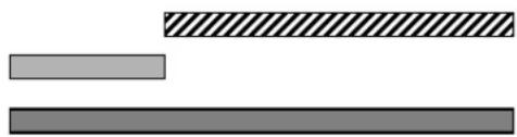
natural_image
Three horizontal bars of different fill styles: solid gray, diagonal striped, and solid black (no text or symbols)Figure 24-17: The same passage of notes after Auto-Recording, with the newly recorded material displayed as the bar with the diagonal pattern.
Anything you play while the Record button is grey is not recorded. This allows you to play along with the sequence and only record between the Punch In and Out times.
PUNCH GUARD
When recording audio tracks, Digital Performer can capture several extra seconds of audio before and after record passes. This feature is called Punch Guard, and it applies to both manual and automatic punch-ins (on audio tracks). For example, if you clicked the record button a little late, you can edge-edit the recorded soundbite to expose several extra seconds of audio before the beginning. If you clicked stop while the reverb was still decaying, you can edge edit past the end of the recorded soundbite to expose the rest of the reverb tail. By default, Punch Guard only happens when manually or automatically punching in, and the pre- and post-roll times are 4 and 1 seconds, respectively, but you can customize these settings as desired, and configure the pre-roll recording behavior. See “Punch Guard” on page 95.
OVERDUB RECORDING
Overdub recording works slightly differently for MIDI tracks and audio tracks, although the basic principle is the same: existing data in the track is preserved. Overdub mode can be combined with Cycle-Recording (described later in this chapter) for drum-machine style MIDI loop recording and multi-take audio loop recording.

Figure 24-18: Digital Performer's Overdub Record mode button.
MIDI overdub recording
In MIDI tracks, overdub mode causes newly recorded MIDI notes to merge with, instead of replace, pre-existing MIDI notes on the record-selected track. The pre-existing notes on the track are not erased. It works as if you recorded one track, recorded a second track to go along with it and then merged the two.
Overdub recording and MIDI controller data
For MIDI continuous controller (CC) data, overdub record mode works differently than with notes. Newly recorded CC data replaces existing data of that same type in the track, according to the automation mode setting for the track in the Mixing Board. For example, with Touch and Latch modes, punch-in occurs when the first CC event is received and continues, replacing existing data of the same type. Existing data stops being replaced when you either stop sending data (Touch mode) or when you stop the record pass (Latch mode). For details about automation modes, see “Automation modes” on page 856.
Audio overdub recording
When overdub record mode is enabled, punched-in audio is layered on top of existing audio. The existing audio remains beneath it, but only the newly overdubbed soundbite will play, i.e. what you see is what you'll hear. See “Overlapping and layering soundbites” on page 393 for more information about how multiple, overlapping soundbites play back in a track. If you change your
mind about the punch-in and wish to remove it, just delete the overdubbed soundbite, which uncovers the original audio beneath.
When overdub recording over existing material, the new material is not merged with the existing material. Instead, it is overlaid on top. To merge soundbites together into one soundbite, place them into separate tracks first and then use the Bounce to Disk command in the File menu. Or use the POLAR window, if you need to do large-scale on-the-fly audio merging.
When overdub record mode is disabled, and you punch-in over existing audio in a track, the existing audio is completely replaced by the newly recorded audio. This record behavior prevents multiple layers of soundbites from piling up on top of one another when you are overdubbing. Instead, punching in will never create overlapping soundbites. Wherever there is a punch-in, the current soundbite is trimmed and a new soundbite begins. However, only those parts of existing soundbites you recorded over are erased. For example, if you record over the beginning of a soundbite, only the portion recorded over is replaced.
If you change your mind about the punch-in and wish to remove it, go back in the Undo History, or remove the punched in soundbite and use the Heal Separation command (“Heal Separation” on page 587) to close the gap.
Overdub record mode lets you choose either method (replacing or layering) for punch-in recording.
Overdub recording and the Conductor Track
Overdub does not affect the Conductor Track; specifically, recording on the Conductor Track while slaved to Tap tempo sync always erases existing tempo events.
Record With Overdub On or Off
Regardless of the current Overdub state, you can override when recording it by using the Record With Overdub On or Record With Overdub Off commands. These do not have key bindings by default, but can be assigned key bindings in the Commands window.
RECORDING MULTIPLE TAKES
A take stores the contents of the track. Each track can have an unlimited number of takes. Takes are an ideal way to record, store, edit, and combine multiple versions of the material in a track. For details, see chapter 51, “Takes and Comping” (page 665).
CYCLE-RECORDING
Several of Digital Performer's features can be combined to provide comprehensive cycle-recording, complete with MIDI Spot Erase and erasing the last pass.
Setting up for cycle-recording
To cycle-record:
1 Click the Memory Cycle and Overdub record buttons in the Control Panel.

Figure 24-19: To cycle-record, turn on the Memory Cycle and Overdub record modes.
The Memory Cycle button causes Digital Performer to loop a section indefinitely. To prevent accidental erasure of the previous record pass, Digital Performer falls out of record mode when it hits the cycle end point, unless Overdub mode is enabled.
2 Set the start and end times of the time range you want to loop in the Memory bar.
For a two measure loop, make the stop time 3|1|000. For a four measure loop, make the stop time 5|1|000. Stop time is always the downbeat of the measure after the last one in the loop. You can set the loop points graphically by dragging the loop repeat barlines in the time ruler of any window that has one, such as the Sequence Editor or the Track Overview, as shown below.
Memory Cycle bar and end points (can be dragged)

flowchart
graph TD
A["5\n1"] --> B["6\n1"]
B --> C["7\n1"]
C --> D["8\n1"]
D --> E["9\n1"]
E --> F["End"]
3 If the playback wiper is not visible in the Track Overview or Sequence Editor, open the Auto Scroll window (View menu > Scroll) and turn on (check) the cursor option for the window.
The wiper shows you where playback is during looping.
4 Set the tempo in the tempo slider.
5 If needed, make sure that the Click is enabled in the Studio menu.
6 Cue Digital Performer to the beginning of the Memory Cycle range.
7 Click the record button in the main transport controls and begin recording.
Cycle-recording in MIDI tracks
When you cycle-record into a MIDI track, each new pass is combined with the MIDI notes from previous passes in the same track take. For example, if the track is currently set to Take 1, and you first record a kick drum, the snare drum notes that you play in the second pass are combined with the kick drum notes in Take 1. You can, of course, change takes at any time.
Editing newly recorded MIDI data
In Digital Performer, recorded MIDI data and digital audio data appears immediately as you record it, before you press the Stop button. For MIDI data, this allows you to edit the data (erase, transpose, quantize, etc.) without stopping cycle-recording. Audio data, however, cannot be edited until after you press the stop button.
Erasing the last MIDI pass and MIDI Spot Erasing You can easily accomplish common MIDI cycle- recording tasks such as erasing the last pass and Spot Erasing by opening the Drum Editor or other edit window while cycle-recording. As you record, notes appear in the window right away, so you can do whatever you want to them without having to press the stop button. You can even insert notes by hand in the looped time range, as well as continuous controllers such as volume controllers.
To quickly erase the last pass while recording a MIDI drum track, open the Drum Editor or MIDI Editor and double-click the note name in the note list, or pitch key on the pitch ruler, respectively, that corresponds to the note you just recorded. Doing so selects all the notes of that pitch in the track. Then hit the delete key.
To Spot Erase graphically, click the note and hit delete.
Spot Erasing from your MIDI controller
A set of cycle-record commands, including a MIDI Spot Erase function, is included in the Commands window. These controls help further provide drum-machine style loop recording by providing the ability to spot erase from your MIDI controller while cycle-recording.
After you've assigned a key to Spot Erase, hold down the Spot Erase key and play back; any notes you hold down on your MIDI controller keyboard that exist in the track are erased as the wiper passes them.

Figure 24-20: Search for the Spot Erase command, and other cycle-recording shortcuts, which can all be assigned to MIDI notes for triggering directly from your MIDI controller.
Changing the MIDI channel or patch on the fly While you are cycle-recording, you can change the device, MIDI channel, or current default patch on the fly while recording as follows:
Next/Previous item Key to press
| Device Shift up-arrow | Shift down-arrow |
| MIDI channel Option/Alt up-arrow | Option/Alt down-arrow |
Default patch (sound) Command/Ctrl up-arrow Command/Ctrl down-arrow
You can also map these shortcuts to MIDI keys on your MIDI controller, so that you can do everything from your MIDI controller during recording. See chapter 9, “Commands” (page 105) for details.
Cycle-recording in audio tracks
When you cycle-record into an audio track (with Overdub Record mode turned on as shown in Figure 24-19), Digital Performer automatically creates a new take for each record pass. For example, if you record a bass line into Take 1, the track will automatically switch to take 2 immediately at the end of take 1. This allows you to play a second take that is completely different than the first.
Capturing the perfect take
By automatically creating takes during audio cycle-recording, Digital Performer allows you to continuously record multiple independent passes into an audio track inside the current Memory Cycle loop points. For example, you could set up the Memory Cycle points around a solo section and then continuously play in multiple passes of the solo, one after the other, without ever stopping. Digital Performer saves each pass separately during recording. When you stop recording, Digital Performer then splits each pass into its own take. You can then choose among takes, or even build a composite take based on parts from each pass using Digital Performer's powerful take comping features; see chapter 51, "Takes and Comping" (page 665).
Audio cycle-recording with punch-in/punch-out Audio cycle-recording can also be used together with Digital Performer's Auto-Record punch in/out feature. You can set up an Auto-Record time range inside the Memory Cycle time range and perform multiple record passes in Overdub Mode as described earlier. Each pass inside the Auto-Record range is stored in a separate take. This allows you to give yourself a bit of pre-roll and post-roll when recording multiple passes.
Audio cycle-recording in the POLAR window
Digital Performer's POLAR window (Studio menu) is specially designed for sound-on-sound audio loop recording. In addition, POLAR has several important advantages over Cycle Recording into a hard disk audio track. Perhaps the most important advantage is that POLAR lets you overdub directly into the current pass, mixing the new material with the existing material in the pass on the fly, as you record. This is possible with POLAR because the audio is being recorded into
the computer's memory, which can be processed much more quickly than data stored on a hard disk. (When cycle-recording into a disk track, each pass is saved separately as a different take, so they are not mixed together, although you can mix them afterwards using the Merge Soundbites command.) For complete details about POLAR, see chapter 31, "POLAR" (page 299).
Creating a permanent loop
After you are satisfied with the MIDI or audio loop you've created, you can make it permanent by inserting a loop into one or more tracks. Use the Loop tool in the Tool palette (Studio menu).
STEP RECORDING
In step recording, MIDI note events are input one at a time, not in real-time. Step recording is done with the Step Record command (Studio menu). Step recording is very useful for entering MIDI music which is too fast or complex to play accurately in real time. It is also useful when entering a score to be converted to music notation programs. For details about step recording, see the chapter 28, “Step Record” (page 271).
RETROSPECTIVE MIDI RECORD
Digital Performer captures MIDI input on record-enabled tracks, whether or not you are actually recording. Use Retrospective MIDI Record (Region menu) to place captured MIDI input into a track. See chapter 29, "Retrospective MIDI Record" (page 283).
RECORDING IN EXTERNAL SYNC
When recording in external sync other than Tap tempo, the Record button is turned off every time the master device stops or rewinds. This is a safety precaution, to prevent accidental erasure of previously recorded data. Refer to chapter 86, "Receive Sync" (page 977) for details on recording while slaved to each type of external sync.
Recording while still-framed
If you are slaving to an external sync source, Digital Performer allows you to remain in record mode while the video parked on a SMPTE frame. To do so, check the Record while still framed option in the Receive Sync settings in the Setup menu.
SAMPLE FORMAT
Digital Performer supports three sample formats: 16-bit integer, 24-bit integer, and 32-bit floating point.
24-bit digital audio recording uses a 24-bit word to describe each sample recorded. 16-bit recording provides 2 to the 16th — or 65,536 — values to record the level of audio for any given sample. 24-bit recording supplies 8 more bits (2 to the 24th), providing over 16 million separate values (16,777,216 to be exact) with which to record the level of any given sample. As you can see, 24-bit recording provides 256 times the resolution — or “fineness” — of 16-bit recording.
24-bit recording has several advantages over 16-bit recording. One is signal-to-noise ratio. In digital recording, each bit provides approximately 6 dB of signal-to-noise ratio (SNR). So 16-bit recording provides a theoretical 96 dB of SNR, 20-bits provide 120 dB, and 24-bits provide 144 dB. With medium to loud audio material, such as a pop music recording, this extra 48 dB of SNR is not a significant advantage. On quiet recordings, however, with long instrument decays or reverb tails, the extra SNR can become much more of an important advantage over 16-bit recording.
The much more significant difference between 16 and 24 bit recording is the resolution, and this factor impacts sound at all levels, soft and loud, even to the untrained ear. As mentioned earlier, 24-bit recording has 256 times the resolution of 16-bit recording. You can readily hear the difference when A/B-ing material recording at the
two different sample formats. 24-bit audio has a noticeably enhanced detail, tightness in the bottom end, and overall depth.
32-bit floating point audio file resolution is an emerging standard used for high-end recording, mixing and mastering applications. The advantage of floating-point representation over fixed-point representation is that it can support a much wider range of values by allowing the decimal point to "float" among the digits than store the value of each sample. For example, a fixed-point representation that has eight decimal digits, with the decimal point assumed to be positioned after the sixth digit, can represent the numbers 123456.78, 8765.43, 123.00, and so on, whereas a floating-point representation with eight decimal digits could also represent 1.2345678, 1234567.8, 0.000012345678, 12345678000000000, and so on. 32-bit resolution allows audio data to be stored with a very high precision and very wide dynamic range.
Digital Performer's mix engine employs 32-bit floating point precision throughout. Recording as 32-bit float is a good way to preserve the floating point precision employed by the Digital Performer mix engine at all stages, particularly if you will be re-recording, bouncing, or applying effects constructively or destructively to your audio.
Choosing the sample format
Digital Performer allows you to use audio files of different sample formats within the same project. You can freely import files at different sample formats and use them without first converting them.
The project's sample format setting (Preferences > Audio Files) applies only to newly recorded or created files; existing files are not affected when you change that setting.
The sample format is saved with the Digital Performer project, and it can be different from project to project. You can also set a default sample format that will be used for new projects. You can change the sample format of a Digital Performer project at any time.
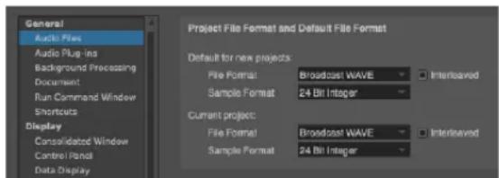
Figure 24-21: Choosing the sample format for a Digital Performer project.
GETTING AN ERROR MESSAGE
Digital Performer keeps close track of whether or not it had any trouble processing the audio data during recording. If conditions prevent it from successfully encoding all the digital audio information, you will be presented with an error message letting you know that an error occurred. These errors can be due to conditions such as:
■ Other background software interruptions
■ A highly fragmented hard disk
■ A hard disk that has an access time that is too slow
■ Other interruptions
See “Audio troubleshooting” on page 1020 for more information about how to handle error messages.
CHAPTER 25 Click and Countoff
OVERVIEW
Digital Performer provides flexible, programmable click and countoff features to help you achieve optimal results during recording.
You can use the click and countoff in any recording situation, from personal record passes to the Hollywood scoring stage.
Click....255
Click Preferences ....256
Click Defaults....258
Countoff....259
Countoff preferences....259
CLICK
The Click is the audible indication of the Metronome beat. The Click can “click” on the beat, or you can customize it to click in any pattern that you prefer. When it clicks on the beat, we refer to the click pattern as a beat click. For the beat click, the beat is determined by each meter change in the Conductor track (or the default 4/4 beat if no meter changes have been added). If the Click is on, Digital Performer will click at the beginning of every measure. The first beat of every measure is slightly accented. The subsequent clicks in the measure depend on how the metronome click value is set in the current meter. To learn more about setting meters, see chapter 59, “Change Meter” (page 749).

Figure 25-1: Click preferences.
Enabling the click
To turn on the Click, choose Click from the Studio menu or press Command/Ctrl-5. To turn off the click, choose it again. When the Click is on, the Click menu item will be checked.
You can also toggle the click on and off by pressing the Click button (which looks like a metronome) in Digital Performer's Control Panel.
The Click & Countoff Options described in the next section provide many options for customizing the click.
CLICK PREFERENCES
The Click Preferences command (Studio menu) provides many settings for the click. You can also open this dialog by Option/Alt-clicking the Click button in the Control Panel, or by opening the Preferences from Digital Performer menu (macOS) or Edit menu (Windows) and clicking the Click list entry (Figure 25-1).
Type of dick
There are three choices for the type of click: Audio, MIDI and Visual Punches.
Audio click
The audio click plays back with sample-accurate precision. You can assign the click to play on any available audio output bundle in your system. A variety of preset click sounds are provided, and you can add an unlimited number of your own custom click sounds.
Audio output
Choose the desired audio output bundle for the click sound from the menu provided.
Click sounds
Choose the desired accented and normal click sounds from the menus provided (Figure 25-2). A variety of preset sounds are provided, including the ubiquitous Urei metronome click sound. Or you can use any compatible audio file you wish using the Choose File menu item.

Figure 25-2: Choosing a click sound.
Audio click volume control
Use the Master Volume slider (Figure 25-1) to control the overall volume of both the accented and normal clicks. Use the individual volume knobs to the right of each click sound menu to adjust their volume relative to each other.
Adding your own click sounds
To add your own clicks to the click sound menus, save them as a mono AIFF, or WAVE audio file, give the file the name you wish to see in the menu, and then drop it into the Clicks folder below. You can add as many click sounds as you wish.
Platform Path
macOS /Library/Application Support/MOTU/Digital Performer/Clicks
Windows C:\ProgramData\MOTU\Digital Performer\Clicks\
Playing the audio click on the computer internal speaker (Mac only)
You can play the audio click on the computer's internal speaker, even when you are using a third-party audio interface product general audio input and output. Just Command/Ctrl-click the Built-in Audio option in the Configure Hardware Driver dialog to select it (along with your third-party hardware driver), as shown in Figure 4-1 on page 27 in the DP4 Getting Started Guide. Then choose Built-in Audio from the audio click's output menu (Figure 25-1).
Disabling the audio click
To disable the audio click, uncheck the Audio check box (Figure 25-1).
MIDI Click
The MIDI click (Figure 25-1) sends a MIDI note for every click. For this option, you must set up an instrument to receive these notes and play a 'click' sound of your choosing. For example, you could use Digital Performer's Model 12 virtual drum module or an external hardware drum machine to play a side stick or rim shots.
Data for MIDI click
These options define what notes are played if the MIDI option is selected. The Accented note is played on the first beat of each measure; the Normal note is played at all other times. Each note has four parameters:
First, you specify the device that will play the accented and unaccented click by choosing it from the menu provided. The list of devices in the menu shows any virtual instruments that are currently available, as well as any external instruments provided by your MIDI device configuration (Setup menu > Bundles > MIDI Devices tab).
Pitch is the pitch of the note, expressed as a scale letter (A-G) (use the number sign # to represent a sharp, or a small letter 'b' to represent a flat) and an octave number. For example, C3 means middle C. Velocity is the attack (on) velocity, expressed as a number from 0-127.
Gate specifies the length of the note in milliseconds (thousandths of a second).
Visual Punches
Visual Punches work just like the punches associated with streamers, as explained in chapter 66, “Streamers, Punches and Flutters” (page 787), except that they flash on-screen on each click. They can be used with or without the audible click. Choose the desired color and size from the menus provided (Figure 25-1). You can also choose the output devices to be used to generate the visual click.
Click options
Always click makes the click audible whenever Digital Performer is counting off, playing or recording.
Only during countoff makes the click audible only during countoff measures. When playback or recording begins, the click will fall silent. See “Countoff preferences” on page 259 for more information about the countoff.
Only when recording makes the click audible only when Digital Performer is in record mode. If the Countoff button is enabled, Digital Performer will also click during the countoff in this mode.
No accent removes the accent from the first click in each measure. This option affects both the audio click and the MIDI click.
Audition Click
If the Audition Click option is enabled, Digital Performer will audition the metronome sound as it is currently configured, at the current tempo.
Master click volume
The Master Click Volume slider (Figure 25-1) controls the volume of the click.
Waveform Editor Beat Click
For details about the Waveform Editor beat click, see "Beat Click Preferences" on page 686.
CLICK DEFAULTS
To access the Click Defaults, choose Preferences from the Digital Performer menu (macOS) or Edit menu (Windows) and click the Click Defaults list entry (Figure 25-3). This feature lets you choose a preferred click pattern for any meter and tempo range that you specify. For example, at a slow 6/8 time, you might prefer to click on eighth note subdivisions, whereas for a fast 6/8 you might prefer to only click every dotted-quarter note. You can create as many default click patterns as you wish for any variety of meters and tempo ranges.
After you customize your default click patterns as desired, Digital Performer will automatically use them whenever the click is enabled and your sequence Conductor Track matches the meter and tempo of each default click.

Figure 25-3: Click Default preferences.
The default click list
Using the Add button (Figure 25-3) to add a default click panel to the list. Each panel in the list defines a click setting for a specific meter within a tempo range. Each default click (Figure 25-4) is defined by the following information in its panel:
■ A meter
■ A tempo range
■ A click

Figure 25-4: A default click.
Default click settings
Choose the desired meter from the menu and then specify a tempo range using the controls provided. Then choose the type of click you would like to hear for that meter within the tempo range you specify. You can specify either a Pattern click or a Beat click, or you may choose a saved custom click pattern from the click menu.
Saving a customized click
If you create a customized click and you wish to save it by name for use with Digital Performer's many other click-related features, use the commands in the click menu (Figure 25-5), which allow you to save, rename and delete as many custom clicks as you wish. To save a pattern click, choose Pattern from the menu, type in the desired pattern as explained in "Pattern click" on page 735, and then choose Save Pattern from the menu (Figure 25-5). Saved clicks then become available from the Saved Patterns sub-menu in all projects. Saved click patterns do not hold any meter or tempo information; they just hold the customized click pattern that you specified at the time that you saved it. To rename or delete a saved click pattern, choose it first and then choose the Rename Pattern or Delete Pattern menu command (Figure 25-5).
Tip: if you begin the name of each saved custom click pattern with the base meter (i.e. "4/4", "3/4", etc.), then all saved click patterns for a given
meter will be grouped together in the Saved Patterns sub-menu. In general, the menu lists them in alphabetical order.

Figure 25-5: Saving, recalling, renaming and deleting click patterns.
Selecting a default click panel
To select a default click panel in the list to audition it or delete it, click anywhere on the panel background. A red border appears to indicate that it is selected.
Audition click
Enabled the Audition Click option (Figure 25-3) to listen to the currently selected default click panel.
COUNTOFF
Enabling the Countoff button causes a countoff of a specified number of measures and/or beats before playback or recording. Clicking on the Countoff button enables and highlights it. You must enable the Click (in the Studio menu) to hear the countoff.

Figure 25-6: The Countoff button produces any number of bars (measures) and/or beats of countoff that you wish.
To set the number of countoff measures and/or beats, Option/Alt-click on the Countoff button. The Countoff preferences will open, where you can enter the number of measures and beats. Several other options are also provided. For further details, see “Countoff preferences” on page 259.
If you choose a countoff that is not simply a whole number of measures, the Countoff button in the Control Panel displays the number of beats in the countoff that you have chosen. For example, the countoff button displays 2 Bars if you have chosen 2 measures and 0 beats. But it displays 9 Beats if you have chosen 2 measures and 1 beat (in 4/4 time).
Use the Countoff button to give yourself time to adjust to the current tempo and prepare for recording. Using the Countoff and Wait buttons allows ample preparation for a recording pass; this is particularly useful in situations where the computer and keyboard are not adjacent.
The counter runs during countoff
The counter updates during the countoff. For example, if you have a two-measure countoff, and you begin playback at 1|1|000, then the counter begins the countoff at -1|1|000 and counts the two measures leading up to 1|1|000. If you begin playback at 9|1|000, the counter starts at 7|1|000 and counts the two measures leading up to 9|1|000.
The movie window and countoff
The movie window runs during countoff. This allows you to see what is happening in the movie during the countoff so that you can better prepare for the downbeat when the countoff is over. It also allows for streamers and punches in the movie window during the countoff.
Indefinite countoff
For an indefinite countoff (the countoff keeps going until you start playing), turn on the Wait button (discussed in the next section) at the same time as the countoff button.
COUNTOFF PREFERENCES
To access the Countoff preferences, Option/Alt-click the Countoff button in the Control Panel. You can also choose Preferences from the Digital
Performer menu (macOS) or Edit menu (Windows) and click the Countoff list entry (Figure 25-7).
Specifying an audio click during the countoff
The Click option (Figure 25-7) lets you hear an audio click during the countoff. Use the menu to choose the type of audible click you would like to hear. The choices are Follow Conductor, Default for Meter, Beat Value and Pattern.
Follow Conductor
The Follow Conductor option causes the Countoff click to follow the Conductor track's click mode.
Beat Value
The beat value option clicks according to the current meter's beat value. See "Change meter basics" on page 749 for an explanation of what a meter's beat value is.
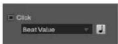
Figure 25-8: Beat click settings.
Default for Meter
The default click is similar to the beat value click, except that the click follows the general click guidelines for various meters and tempos as prescribed in "Click Defaults" on page 258. For example, in 12/8 time, the default click clicks on dotted quarter notes at fast tempos and eighth notes at slow tempos.
Pattern
The Pattern click produces a click according to a pattern specified, with a single specified sound (such as a drum kit). See "Pattern click" on page 735.
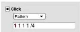
Figure 25-9: Pattern click settings.
Saved pattern clicks
You can also choose any saved pattern clicks from the Click menu. This menu provides the same features for saving and managing custom click patterns as described in "Saving a customized click" on page 258.
Figure 25-7: Countoff options.

Countoff length
The length of the countoff (Figure 25-7) can be specified in a number of whole measures and/or individual beats using the Countoff n measures and y beats setting. Accordingly, the Countoff button in the Control Panel ("Countoff" on page 212) displays the number of beats in the countoff, if you have chosen a countoff that is not a whole number of measures. For example, the countoff button displays 2 Bars if you have chosen 2 measures and 0 beats, and it displays 9 Beats if you have chosen 2 measures and 1 beat (in 4/4 time).
Countoff only when recording
The Countoff only when recording option causes the countoff to occur only before recording, not before playback or any other function.
Visual countoff
The countoff preferences (Figure 25-7) allow you to trigger visual streamers and punches during the countoff. These visual effects can be produced by supporting hardware (as listed in “Supported film cue hardware” on page 788) and displayed on a video monitor connected to the hardware. They can also be generated by Digital Performer, which overlays them on video being played in Digital Performer’s movie window. For more information about working with visual streamers and punches, see chapter 66, “Streamers, Punches and Flutters” (page 787).
Punches in sync with click
The Punches in sync with click option (Figure 25-7) creates a visual punch in time with the click during the countoff. Choose the desired color and size. For situations that require silence during the countoff, you can turn off the click (unchecked its box in Figure 25-7) and use the visual punch instead.
Warning streamer before countoff
The Warning streamer before countoff option (Figure 25-7) creates a streamer leading into (prior to) the countoff. Choose the desired color and duration of the warning streamer.
Warning streamer at end of countoff
The Warning streamer at end of countoff option (Figure 25-7) creates a streamer leading into the start time (the downbeat at the beginning of sequence playback, at the end of the countoff). Choose the desired color and duration of the start time warning streamer. You may want to choose a different color than the before countoff streamer.
CHAPTER 26 MIDI Monitor
OVERVIEW
The MIDI Monitor window displays incoming MIDI activity, broken down by input device, MIDI channel, and type of data. This feature is handy when testing hardware, tracing problems in your MIDI system, or monitoring time codes or other special MIDI data. The MIDI Monitor window will function whether active or inactive.
OPENING THE MIDI MONITOR WINDOW
Choose MIDI Monitor from the Studio menu; the window will appear. To move it, click in the title bar and drag to the desired location. To close the MIDI Monitor window, click in the window's close button.

Figure 26-1: The MIDI Monitor window. The "Co" lights are MIDI system common data indicators. They light up when system exclusive data is being received from the device.
BASICS
The MIDI Monitor window consists of one row of activity lights for each MIDI device that has its MIDI OUT connected to the MIDI interface in your current MIDI device configuration (Setup menu > Bundles > MIDI Devices tab). It therefore displays any devices that have the ability to send MIDI data to Digital Performer. Each row contains 16 MIDI channel indicators that are
normally unhighlighted; they highlight to indicate incoming MIDI data. Each row includes a light for system common data and real-time data (sync).
If several devices are listed below one row of lights, as demonstrated in Figure 26-1, this indicates that the devices are connected to the same MIDI port via daisy chaining through their MIDI thru ports.
The Input Filter has no impact on the MIDI Monitor window's display.
The MIDI Monitor window only displays incoming MIDI activity — only data being received by Digital Performer from somewhere else —not outgoing data being sent by Digital Performer.
Channel Activity indicators display MIDI activity by MIDI channel. Most normal MIDI data will cause one of these indicators to light up; for example, pressing a key or moving the pitch bend wheel on a controller keyboard will cause the corresponding Channel Activity Indicator to turn black.
The System Common indicator, labelled "Co", indicates incoming system common data, such as system exclusive data, tune request, Song Position Pointer, and Song Select commands.
The System Real-Time indicator, labelled “Rt”, includes MIDI beat clocks and System Reset commands. This type of data is used to synchronize devices, and is generated by most sequencers, drum machines, and SMPTE-to-MIDI converters. System real-time data is not assigned to a particular channel and therefore has just one indicator per port.
Active sensing messages, which are sent by some brands of MIDI equipment, are ignored by the MIDI Monitor window. To see if your equipment is “on-line” and working correctly, send note data and observe the Channel Activity indicators.
CHAPTER 27 Audio Monitor
OVERVIEW
The Audio Monitor (Studio menu) displays important information about the recording settings for each digital audio input.
Audio Monitor quick reference ....265
Mini-menu quick reference....266
Buses in the Audio Monitor....266
Virtual instrument inputs....266
Naming a takefile before recording....267
Changing the takefile location before recording .....267
Adjusting the level meter range .....268
Setting the input level....269
Other ways to monitor input levels .....269
AUDIO MONITOR QUICK REFERENCE
Input (IN)
The leftmost column in the Audio Monitor indicates each audio input provided by your hardware.
Level meters
The level meters work like a standard VU meter on a mixing console. They indicate the amplitude of audio being recorded on each input. The meters in the Audio Monitor show input levels only. Playback levels are displayed in the level meters in
the Mixing Board window. (See “Level meters” on page 839.) The Level Range mini-menu command allows you to change the range of the meters from 6 dB to 42 dB.
Takefiles
The Takefile column displays the name of the audio file that will contain the next portion of audio to be recorded on each input. As soon as you record-enable an audio track, Digital Performer automatically creates an audio file with a name that matches the name of the track being recorded into, followed by a take number (e.g. Guitar-3). These automatically generated audio files are referred to as takefiles. Here's a brief summary of what you can do with takefile names:
To do this Do this to the takefile name
| To rename the takefile Uncheck the mini-menu option called 'Base file names on track names' and then Option/Alt-click the takefile name. |
To relocate the takefile Double-click
| To select one or more takefiles for mini-menu commands | Click to select a single takefile;Shift-drag to select a range;Command/Ctrl-click to select or deselect multiple non-contiguous takefiles |

Figure 27-1: The Audio Monitor window.
Available record time
Displays the total amount of time available for recording on the hard disk where the take file is currently located. Time is displayed in minutes and seconds. Click the value to toggle between minutes:seconds and megabytes (MB). Option/Alt-click to toggle all inputs at once. One minute of audio at 44.1 kHz takes up about 5 MB of hard disk space. For other sample rates, see “How much disk space does audio require?” on page 58 in the DP4 Getting Started Guide.
Take Folder
Displays the current location on disk of the takefile. Click to toggle the display between showing the full path name and the abbreviated path name; hold option to toggle the display for all takefiles at once.
MINI-MENU QUICK REFERENCE
Set Take Folder: Lets you change the location of the currently selected takefiles in the Audio Monitor window. Click, Shift-click, or use Select All to highlight the take file names before choosing this command.
Level Range: Lets you choose among several different level ranges for the meters in the Audio Monitor, from 6 dB to 42 dB.
Retain Clip: When checked, this command causes the clip indicators to remain lit after clipping has occurred (instead of only remaining lit as clipping occurs). Click the clip indicator to turn it off.
Base file names on menu: When the “Track” option is checked, this command causes takefile names to be derived from the name of the track currently being recorded into. For example, When this option is checked, and the currently record-enabled track is named Guitar, the takefile name will be called Guitar-x, where x is a take number automatically assigned by Digital Performer. Likewise, when the “Input” option is checked, this command causes takefile names to be derived from the name of the input of the track currently being recorded into. Use “Custom” to choose your own names.
Scroll to Record Enabled Inputs: When checked, the Audio Monitor will automatically scroll to the record-enabled inputs.
BUSES IN THE AUDIO MONITOR
The Audio Monitor shows both inputs and busses. For example, under the MOTU Audio System, typically you'll have several hardware inputs, along with sixteen or more buses. (Under the MOTU Audio System, the number of available buses is adjustable. See “Stereo buses” on page 33 in the DP4 Getting Started Guide.) Bus inputs are displayed in the Audio Monitor because you can assign a bus to the input of a track, which you can then record. When you record a track that has a bus as its input, the audio input from the bus gets recorded onto your hard drive into the takefile shown for the bus in the Audio Monitor window. To help you identify them, takefiles for bus inputs are given a default name that includes the word bus.
VIRTUAL INSTRUMENT INPUTS
The Audio Monitor also displays any virtual instrument inputs that may currently be available to Digital Performer, from instrument plug-ins or virtual instrument software that is running concurrently with Digital Performer. Any inputs that appear in the Inputs tab of the Bundles window (Studio menu) will also appear in the Audio Monitor.
NAMING A TAKEFILE BEFORE RECORDING
If the Base file names on >Track mini-menu item is checked (Figure 27-3 on page 268), then Digital Performer will automatically derive the audio file name from the name of the track currently being recorded into.
If the Base file names on >Input mini-menu item is checked (Figure 27-3 on page 268), then Digital Performer will automatically derive the audio file name from the name of the input of the track currently being recorded into.
If you want, you can choose the Base file names on >Custom mini-menu item and give the takefile any name you wish. To manually set the takefile name before recording, choose the Base file names on >Custom mini-menu item and Option/Alt-click the takefile name in the Audio Monitor. To rename the audio file after it has been recorded, Option/Alt-click its name in the Soundbites window.
Digital Performer automatically keeps track of the audio files associated with the project, regardless of where you store them on your hard disk. (For more information, see chapter 5, “Audio File Management” (page 57).) There might be times, however, when you would like to change the takefile location.
By default, Digital Performer places takefiles into a folder named Audio Files, which it automatically creates in the project folder when you first open a new project. If necessary or desired, you can move the takefile to a different disk or folder. For example, you may want to organize your takefiles into folders as you record them for convenience. Each input can be assigned a different location, allowing you to record into separate folders and even hard drives. For general tips about audio file management, see chapter 5, “Audio File Management” (page 57).
To change the location where a takefile will be recorded:
1 Double-click the takefile name in the Audio Monitor.
Alternatively, you can click the takefile name once to highlight it and choose Set take folder from the mini-menu. The Change Directory window appears.
2 If necessary, use the Change Directory window to go to the desired folder or location on your hard disk.
3 If you want to create a new folder, click New Folder.
4 If you want to select an existing folder, click the folder's name in the list to highlight it, and click Choose.
Changing the takefile location for several (or all) inputs once
To change the takefile location for all inputs at one time, click and Shift-click the takefiles you want to change and then choose Set Take Folder from the Audio Monitor mini-menu.
Organizing audio files into folders as you go
Let's say you're currently adding the following to a sequence: backup vocals on input 1 and acoustic guitar on input 2. You also know you will be recording at least several takes for each part, thus creating several audio files for each.
In this situation, you might find it handy to place the vocal takes into one folder and guitar takes (record files) into another so that you don't get the vocal audio files mixed up with the guitar audio files. (It isn't absolutely necessary to separate
record files like this, but the more takes you record, the easier it will be to sort through them later on, if necessary.)
Checking the current takefile location
The current location of the takefile for each input is shown in the Take Folder column in the Audio Monitor as shown below.
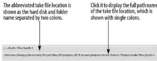
To view the full path to the takefile's location:
1 Click the take folder location.
2 Click the window's zoom button in the title bar to expand the window so you can see the full path name.

Figure 27-2: Click the zoom button to expand the window.
3 Click the zoom button again to return the window to its original size and position.
You can also double-click the path to open a window to that location.
Remembering takefile locations
Digital Performer remembers the takefile location settings when you save the file so that it will remember to put takefiles in the same folder the next time you record. If you like, you can save takefile locations in your new template file using the Save As Template command.
ADJUSTING THE LEVEL METER RANGE
By default, the level meters have a full range from -42 dB to zero dB (clip). The Level Range mini-menu command lets you adjust the range to as small as 6 dB. Just choose the desired range from the menu. You can even change it during recording. For a signal with a wide dynamic range, use a larger value; for a signal with a fairly consistent and narrow dynamic range, use a smaller value and record it as close to zero as possible. But be sure not to clip. (See the next section.)

Figure 27-3: The Audio Monitor mini-menu.
Using the clip indicator to avoid clipping
Each sample in a digital audio signal is expressed as a number within a certain range. (In 16-bit audio, the value of each sample is expressed as a binary number containing 16 bits, which provides a range of over sixty five thousand values.) If the level of audio being recorded or played back exceeds the range that can be expressed, the result is clipping. Those portions of the audio waveform that exceed the maximum value of the dynamic range get cut off at the maximum value that can be expressed. This causes the top of the waveform to get chopped off, giving it a shape more like a square wave, as shown below. The clipped audio signal on the left will sound distorted:

Clipped Not clipped
When clipping occurs, the level meter's clip indicator will light up as shown below:
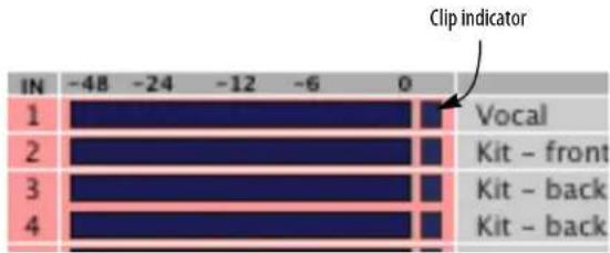
Retain clip
If Retain Clip is checked in the Audio Monitor mini-menu, the clip indicator lights up at the first occurrence of clipping and remains lit as a reminder that clipping has occurred. To clear the clip indicator, click it. This is a convenient way to keep track of clipping without having to stare continuously at the meter.
The Retain Clip setting here in the Audio Monitor also affects the clip indicators of the level meters in the Mixing Board window and the Meter Bridge (page 885).
Clearing the clip indicators
Click an indicator to clear it. Double-click it to clear all indicators, or choose Clear all clipping indicators from the Studio menu.
Scrolling to the record-enabled inputs
If the Audio Monitor has a lot of channels showing, this menu item can come in handy. When it is checked, the Audio Monitor will always scroll to the record-enabled inputs so you can easily see activity on the input without having to scroll the window manually.
SETTING THE INPUT LEVEL
When recording, get as high a level as possible without any clipping. Before you record, always sample the entire range of the audio input you will be recording and adjust the input level accordingly. Ideally, the loudest part of the signal should peak just below zero dB (when the meter is all the way up without the clip light). Digital clipping is harsh, with virtually no headroom, so try to avoid it as much as possible.
OTHER WAYS TO MONITOR INPUT LEVELS
In addition to the level meters in the Input Monitor (Figure 27-1 on page 265), long throw metering is available in both the Mixing Board (“Level meters” on page 839) and the Meter Bridge (“Meter Bridge” on page 885). The Meter Bridge provides audio track input monitoring, whereas the Mixing Board provides both MIDI and audio track input monitoring.
CHAPTER 28 Step Record
OVERVIEW
Step Record (Studio menu) is an alternative to real-time MIDI recording. It waits for you to enter MIDI notes one at a time and allows you to specify the duration of each. With it, you can enter passages too complex for real-time entry. Whatever you enter in Step Record will be rhythmically accurate (it won't need quantizing). This is particularly useful for entering music for conversion to music notation by the QuickScribe Editor other music notation software.
| Step Record quick reference | 271 |
| Basics | 272 |
| Getting ready | 272 |
| Performing step entry | 276 |
| Step recording during playback | 279 |
| Step Record shortcuts | 279 |
| Be careful | 282 |
| Hints | 282 |
Figure 28-1: The Step Record window lets you input notes one at a time in non-real time. You can hear the rest of the MIDI tracks in the sequence play on each step, if you like, and notes appear in the track immediately as you record. There are also randomization settings to "humanize" your step-record performance as you enter it.
The Current record track is selected from this menu and displayed for reference. This is the track that is being recorded into.
The Step Duration buttons allow you to set the duration for the step.
The Dot and Double Dot buttons extend the duration chosen with the step duration boxes by one half or three quarters of the selected value, respectively.
The Tick box displays the duration in ticks for the step. You can enter the duration for the step directly by clicking in this box and typing in the number of ticks.
The Tuplet duration box allows you to enter any kind of tuplet: triplets, quintuplets, etc.
The Backstep button erases the previous step.
The Step button records the current step with the chosen duration.
The Beat button records the current step and advances you to the next beat.
The Measure button records the current step and advances you to the next measure.
Checking the Auto Step check box causes the current step to be recorded each time a key is released on the MIDI controller.
The Lock to Transport setting connects or disconnects the Step Record window to or from the main transport controls and counter. When connected, Digital Performer plays all tracks as you step, and the main Counter follows the current step. When disconnected, the Step Record
window steps independently of the main Counter. While disconnected, you can step record while Digital Performer is playing back.
The Duration box sets the duration of the notes being entered, where 100% is the length of the current step.
The Offset box shifts the attack time of the note being entered earlier or later than the current step.
The Solo Playback check box option solos the track being step-recorded into. When unchecked, all play-enabled tracks will play as you step.
Step record mini-menu
Click with Each Step causes a click to sound when a step is recorded.
Note Durations: Lets you assign a MIDI controller such as a modulation wheel to control note durations as you enter them.
Note Offset: Lets you assign a MIDI controller such as a pitch bend wheel to control the note offset as you enter notes.
Clear MIDI Events: Clears any events that are currently shown in the step bar.
BASICS
Step Record is primarily used to enter notes and rests. For information about how to step record controllers, pitch bend, and patch changes, see "Step recording controllers, patch changes, or pitch bend" on page 279 in this chapter.
Step recording notes and rests
A step consists of a particular duration (an eighth note, for example). In addition, a step can contain one or more notes that are being held over from previous steps. All notes in a step last for the complete duration of that step.
A step recorded passage contains a series of adjacent steps. Each step has a duration specified by the user. A step can contain:
■ nothing: i.e. a rest
■ struck notes: Notes with attacks at the beginning of the step. Unless held into the next step, these will be released at the end of the step.
■ held notes: Notes with attacks in a previous step. Unless held into the next step, these will be released at the end of the current step.
In Step Record, the time at the beginning of a step is represented in measure time. In 4/4 time, a quarter note beginning at 1|2|000 end just before 1|3|000. If a second quarter note directly follows the first, it will begin on 1|3|000. Two eighth notes following just after will begin on 1|4|000 and 1|4|240, respectively.
A rest is a step containing no notes. It is an “empty” duration. Although rests are registered in the Step Record window, they do not appear in edit windows: they are the spaces between note events.
Velocity information is recorded in Step Record unless specifically disabled by the Input Filter (Setup menu).
GETTING READY
Before selecting Step Record, you should do the following:
1 Set up a MIDI track as described in “Preparing a MIDI track for recording” on page 235.
2 (Optional) Open the Sequence Editor, Event List, MIDI Editor, QuickScribe Editor, or other edit window for the track on which you are recording.
You can open several edit windows, if you like. This is recommend because it allows you to see what you are step recording as you go.
3 If you are using the Sequence Editor, MIDI Editor, or QuickScribe Editors, make sure these windows are set to follow the counter in the Auto Scroll preferences, including their playback wiper.
4 Set the Counter to the time you wish to start recording.
If you want to start at the beginning of the sequence, set the Counter to 1|1|000.
5 If you don't want to erase pre-existing music on the track and want to merge new material with old, click the Overdub record mode button in the Control Panel.

Figure 28-3: The Overdub Record mode button lets you record MIDI notes into a track without erasing what is already there.
6 Select Step Record from the Studio menu.
The Step Record window appears.

Figure 28-2: The Step Record window, along with the Event List, Sequence Editor, and QuickScribe Editor for the track being step recorded into. Notice that since Auto Scroll has been enabled in the Setup menu, the windows are scrolling as notes are entered. Also notice that the Sequence and QuickScribe Editors have the scrolling cursor to indicate the current step location.
The current step indicator in the Step Record window displays the starting location for the first step; this is automatically set to the current Counter location.
When you are finished setting up, you will see the Step Record window, along with one or more of the edit windows for the track. The notes that you step record will appear in the edit windows as you proceed with step recording.
Setting step durations
The duration buttons are used to set step durations. Clicking on a duration button will highlight it and assign that duration to the step. Durations remain set until changed, allowing you to enter a stream of notes with the same duration very quickly.
To select more than one duration box at once, hold down the Shift key while clicking on the desired duration box(es). When more than one box is selected, the step duration is equal to the sum of the selected values.
You can also select durations using the extended numeric keypad. (On Windows, make sure the Num Lock key is engaged to use these keypad shortcuts.) Press one of the number keys to select a duration. It remains selected until you deselect it. To deselect it, press it again.
These Step Controls are completely customizable. See chapter 9, "Commands" (page 105).
Setting dotted durations
The dot and double dot boxes can be used to modify the selected step duration. If the dot box is selected, it signifies a dotted step duration, i.e. one and one half the value of the highlighted duration. If an eighth note and dot are selected, the step duration will be a dotted eighth note, i.e. a metrical value of an eighth plus a sixteenth. If the double-dot box is selected, it signifies a doubledotted step duration, i.e. one and three quarters the value of the highlighted durations. If a quarter note and double dot are selected, the step duration will be a double-dotted quarter note, i.e. a metrical value of a quarter plus an eighth plus a sixteenth. Only one of the dot boxes may be active at a time.
Entering a tuplet duration
The tuplet box can be used to set the step duration to a tuplet value, allowing you to enter triplets, quintuplets, septuplets, etc. These values are expressed in the standard way, x in the time of y durations. The tuplet box, when active, actually modifies the duration you choose in the duration boxes (including the dot and double dot modifiers). For example, at 480 ppq, an eighth note duration is equivalent to 240 ticks. If the tuplet box is set to “3 in the time of 2”, step duration (displayed in the tick box) becomes 160 ticks, one third of a quarter note.
Here are a few additional examples: eighth note triplets are three equal duration notes in the time of two eighth notes. Quintuplet sixteenth notes are five equal notes in the time of four sixteenth notes.
The tuplet box is active when the check box next to the word “Tuplet” is highlighted. Make sure to deselect it when you have finished entering the tuplet values. You may enter any number of notes in the space of any other number. Digital Performer does all the necessary calculations for the proper durations; you needn’t worry about the exact number of ticks a single tuplet duration will require.
Specifying an exact number of ticks for a step
Digital Performer computes the number of ticks for each duration automatically when you click on the boxes. You can directly specify the exact number of ticks for a step by editing the numeric duration specified in the tick box. All duration boxes will be deselected to indicate that you are entering the number of ticks directly. At this time,
you can type in a new duration value. Click on any duration box to return to specifying durations as note values.
Choosing a note duration
Normally, the duration of the note being step-entered is 100%, which makes it exactly as long as the step itself. For example, if the step was a quarter note, the note would be 480 ticks long (at 480 ticks per quarter note resolution).
Often, however, you might want to choose a different duration than the length of the step. For example, you might want to enter staccato quarter notes: at 480 ppq, the step duration is 480 ticks, but the duration of the notes should be much shorter—say around 60 ticks.
To set a duration that is longer or shorter than the current step duration, type in a percentage below or above 100%.
The duration can be controlled on the fly using a pitch bend or modulation wheel. For more information, see “Step Record shortcuts” on page 279.
Generating random note durations within a range
Note durations can be generated randomly within a range. Choose Note Durations from the Step Record mini-menu. In the duration range, as shown in Figure 28-9 on page 280, enter the lowest and highest percentage that you would like to use. 100% equals the current step duration, so if you'd like to be able to enter notes longer than the step duration, make the top value be above 100%. Check the "Randomize Durations within a range" option.
Setting default step-record durations
Digital Performer allows you to control the duration of the notes that you are step-entering independently of the step duration. For example, if you are entering quarter notes, the step duration is 480 ticks. However, if you would like the quarter notes to be played in a staccato fashion, you would probably set the duration to approximately 120 ticks or some other value less than 480 ticks.
One way to control the duration is with the duration option described earlier in “Choosing a note duration”.
Often, however, you might like to select a different duration for each type of note (quarter note, half note, whole note, sixteenth, etc.). For example, you might want quarter notes to be 80% of their step duration, half notes to be 100%, and sixteenth notes to be 65%, where each duration has an independent duration.
You can set up default durations for each note duration as follows:
1 Double-click the duration button that you would like to set.
A dialog box appears in which you can set the default duration for that note.
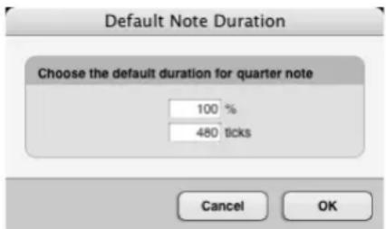
Figure 28-4: The Default Note Duration window (which you open by double-clicking a duration button in the Step Record window) lets you choose a duration for each note length that is different than its step size. For example, you may want to enter a lengthy passage of staccato sixteenth notes. In this case, their step size is still 120 ticks (at 480 ppa), but you would want to make their duration shorter, perhaps 60 ticks.
2 Type in the desired duration.
You can either type a percentage or a number of ticks. In either case, the other text box will update to reflect the value you enter. For example, if you entered 50% in the box above, the tick value box would change automatically to 240 (at 480 ppq).
3 Click OK.
4 Repeat this procedure for each desired duration.
Choosing a note offset
Normally, step entered notes are inserted exactly at the tick location of the current step. The offset option allows you shift their entry a few ticks before or after the current step location. Offset is ideal for passages in which you'd like to push or lay back the feel.
To place notes a certain number of ticks before the current step location, type in a negative number of ticks in the offset text box.
To place the notes a certain number of ticks after the current step location, type in a positive number of ticks.
The offset can be controlled on the fly using a pitch bend or modulation wheel. For more information, see “Step Record shortcuts” on page 279.
Generating random note offsets within a range
Note offsets can be generated randomly within a range. To do so:
1 Choose Note Offsets from the Step Record mini-menu.
2 In the offset range, enter the earliest and latest offset that you would like to use.
Use a negative number to indicate the earliest offset, such as -15.
3 Check the “Randomize Durations within a range” option.
4 Click OK.
Soloing the record track
Normally, all play-enabled tracks play along with you as you step record. However, if you want to mute all other tracks in order to solo the one being recorded into, click the Solo Playback check box.
PERFORMING STEP ENTRY
After setting the step duration, you are ready to enter notes. When entering them, you can proceed to each next step automatically (with the Auto Step option checked) or manually (with the option unchecked).
Stepping automatically
Enter one or more enter notes with Auto Step in the following manner:
1 Hold down one or more notes on your MIDI controller.
2 Release the notes to enter the step.
When Auto Step is enabled, a step is automatically recorded when you release a key on your MIDI input keyboard, just as if you had pressed the Step button. This makes entry quick and easy.
For example, using Auto Step, you could enter an eighth note scale without using the step button: just set the duration to an eighth note and play the scale on your MIDI keyboard.
When using Auto Step, be aware of the following things:
Play staccato: make sure that the notes for each step are attacked and released crisply, with clean gaps between the notes. If the release of a note overlaps with the attack of the next one, you may get two notes in a step in which only one was
intended. Don't worry about the duration. Remember, it is determined by the duration option.
Wrong notes will be recorded automatically. If you hit a wrong note, you must use the Backstep button to erase it and re-enter the note or chord. This differs from manual step mode in which you can replay the notes as many times as you like before you click on the Step button, and only those notes being played at the moment you click on the button are recorded.
Stepping manually
At times, you may wish to choose when to proceed to the next step, such as when you are holding a note or chord through several steps. To do so:
1 Hold down one or more notes on your MIDI input keyboard.
2 Click on the Step button.
3 Release the notes.
This will cause one step to be recorded containing the notes you played. Clicking on the Step button will record those notes which are being held down on the controller keyboard. The step will not be completed until you press the Step button. If you continue to hold the same notes down and press the Step button again, the notes will be recorded as "held" since they were not released in the previous step.
If you play a wrong note, simply play the correct one before pressing the Step button.
Entering rests
Rests are entered by pressing the step, beat, or measure buttons with no notes held down. This records a step with no notes for the chosen duration.
Hearing a click after each step
When the Click with Each Step mini-menu item is enabled, it causes a click to sound every time a step is entered. This is highly recommended when using Auto Step, as it is a useful indicator of step completions.
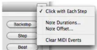
Figure 28-5: The "Click with Each Step" mini-menu item produces a click every time a step is entered.
Listening to what you have recorded
When you are finished step recording, and you'd like to hear what you have done, press Rewind, or cue to the desired start measure. Then press Play.
Disconnecting the counter from step record
Notice that when you rewind and play back, or do just about anything else besides step-recording, the Lock to Transport button in the lower left corner unchecks. (You can also uncheck it by clicking it.) This indicates that the main Counter in the Control Panel is no longer locked to the current step location in the Step Record window.

Figure 28-6: The Lock to Transport button is important: it engages (and disengages) step recording from Digital Performer's main transport controls. If you don't want the rest of the sequence to play as you are step-recording, uncheck this button.
In this mode, the Step Record window acts entirely independently of Digital Performer's main transports (play, stop, rewind, etc.), as well as the main Counter. Thus, you can play, rewind, fast forward, stop, and otherwise cue around in the sequence completely independently of where you are step recording.
In this mode, other tracks do not play along with the track that you are step recording into. To get them to play along, click the Lock to Transport box again to highlight it. Doing so locks the transports to Step Record.
Connecting the main counter to step record
If, as you Step Record, you would like other tracks to step along with you, enable Lock to Transport before you begin. Doing so causes Digital Performer's main Counter to follow the current step indicator in the Step Record window. All play-enabled tracks will play as you step through the sequence.

Figure 28-7: Turning on Lock to Transport engages the Step Record step buttons to Digital Performer's main transport controls so that the entire sequence plays as you step record.
Changing the current step location
To change the current step location:
1 Click the Current Step location to edit it.

2 Type in the desired location.
3 Press the return key.
4 If you wish to connect the main Counter to the new Step Record location, check the Lock to Transport box.
Doing so causes the main Counter to follow you as you step, and all play-enabled tracks will play with you as you step.
Displaying notes as you step enter
Notes that you step enter appear in the edit windows of the track as you enter them. To view them either during or after entry, open any edit window, such as the Event List, MIDI Editor, and/or QuickScribe Editor for the track on which you are recording. See Figure 28-2 on page 273.
Erasing the last step with the backstep button
Pressing the Backstep button will erase the step you just entered (the one displayed just above the current step bar). After pressing the Backstep button, the time in the current step bar will be the exact starting time of the step erased with the Backstep button.
Stepping to the next beat or measure
The Beat and Measure buttons are special step advance buttons. They compute the duration necessary to get to the next beat or measure: the step is recorded using that duration and you are advanced to the next beat or measure for the next step. For example, if the current step is on 2|1|212 the meter is 4/4, and Digital Performer's PPQ resolution is set to 480, when the Beat button is pressed, a step of 268 ticks will be recorded and the next step will be entered at 2|2|000. If the Measure button is pressed, a step of 2|268 (2 quarter notes and 268 ticks) will be entered and the next step will be entered at 3|1|000.
Changing the current record track
To change the current record track, click the "Recording on" menu and select a different track.

Figure 28-8: Choosing a track to step-record into.
Adding to existing material in a track
You can add to existing material in a track as long as you first turn on Overdub record mode with the Overdub record button in below the main transport controls. Otherwise, the newly step recorded notes will replace existing notes in the track.
Step recording controllers, patch changes, or pitch bend
To step record a controller event, patch change, or pitch bend event:
1 Play the event.
The event appears in the current step bar.
2 Press the Step button or any other motion button to record the event.
Events, such as patch changes, controllers, and pitch bend do not trigger auto step. In these cases, play the event and proceed to the next step by pressing the Step button (or any other motion control button.)
STEP RECORDING DURING PLAYBACK
Step recording can be done during playback. For example, you can step record notes into a loop and have Digital Performer play back the loop in real time as you build the loop. This can be ideal for building drum loops with Step Record.
To Step Record into a loop during playback:
1 Choose Step Record from the Studio menu and uncheck the Lock to Transport box.
This disconnects the main Counter from Step Record.
■ Lock To Transport → □ Lock To Transport
2 Set up a loop in a track.
If necessary, you can initially make the loop repeat infinitely while you are building it and later on change it to the desired number of repetitions.
3 Choose the track with the loop from the "Recording on" menu in the Step Record window.
4 Click the Overdub record button located just below the main transport controls to enable Overdub record mode.
This allows you to step record over the same time range in the loop without erasing existing material.

5 Set up any other Step Record options as desired, such as Solo Playback and Auto Step.
6 Press the Play button to begin Playback.
As the sequence plays, notice that the Current Step in the Step Record window remains where you begin.
7 Click the current step counter to type in to the location where you want to begin step-recording.
8 Begin step-recording as desired.
9 When you reach the end of the loop, edit the current step indicator to step-record the next pass through the loop.
As Digital Performer keeps playing, you can repeat this step as many times as necessary as you build the loop. As you build it, you will continue to hear it playback.
10 When you are finished, press Stop.
STEP RECORD SHORTCUTS
All of the functions in the Step Record window are available as shortcuts in the Commands window. This allows you to map them to your MIDI controller so that you can perform the entire step recording process from in front of your MIDI instrument, rather than in front of your computer screen.
Keyboard shortcuts in brackets are located on the numeric keypad.
Command Keyboard shortcut
| Backstep [0] | |
| Step [Enter] | |
| Beat [+] | |
| Measure [-] | |
| Tuplet on/off [/] | |
| 128th note [9] | |
| 64th note [8] | |
| 32nd note [7] | |
| 16th note [6] | |
| 8th note | [5] |
| Quarter note | [4] |
| Half note [3] | |
| Whole note | [2] |
| Double whole note | [1] |
| Dot | [.] |
| Double dot | [=] |
| Auto Step on/off | [*] |
| Solo Playback on/off | P |
| Audible Click on/off | K |
| Clear MIDI Events | [Clear] |
Controlling duration with a MIDI controller
You can set up Step Recording such that a mod wheel or other continuous controller controls the duration of the notes being inserted.
To assign a pitch bend wheel, mod wheel, or data slider to the duration:
1 Choose Note Durations from the Step Record window mini-menu.
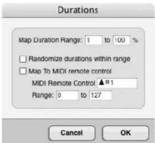
Figure 28-9: The Note Durations feature lets you adjust on the fly the durations of the notes you are step-recording with an external MIDI controller, such as the pitch bend wheel on your controller keyboard.
2 For duration range, enter the lowest and highest percentage that you would like to use.
100% equals the current step duration, so if you'd like to be able to enter notes longer than the step duration, make the top value be above 100%. The maximum value you can enter is 200%.
3 For the MIDI remote control, enter the controller type, and enter a range of controller values that will be mapped to the duration range you specified above.
For example, if you specify a duration range of 50% to 150%, and you specify a controller range of 0 to 100, when you move the mod wheel (pitch bend wheel, or data slider) to 100, the duration will be set to 150%. Likewise, if you move the controller to 0, the duration value will be set to 50%. You can enter any of the above values by highlighting the text box with the Tab key and moving the controller wheel or slider.
Tip: use your pitch bend wheel so that you can always "snap" back to each note's normal duration.
4 To enable the MIDI remote control, click the MIDI Remote Control check box.
5 If you wish notes to be assigned a random duration within the duration range you've chosen, click the "Random Duration within range" check box.
6 Click OK to confirm your choices.
Now you can control the duration with your mod wheel. As you move the wheel, notice that the duration value changes in the Step Record window.
Controlling the offset with a MIDI controller
You can set up Step Recording such that a mod wheel or other continuous controller controls the offset of the notes being inserted.
To assign a pitch bend wheel, mod wheel, or data slider to the offset:
1 Choose Note Offset from the Step Record window mini-menu.

Figure 28-10: The Offset feature lets you adjust on the fly the placement of the notes you are step-recording with an external MIDI controller, such as the pitch bend wheel on your controller keyboard.
2 For the offset range, enter the earliest and latest value over which you would like to set the offset.
Type a negative tick value in the first text box for the earliest value; type a positive tick value in the second box for the latest value.
3 For the MIDI Remote Control, enter the controller type, and enter a range of controller values that will be mapped to the offset range you specified above.
For example, if you specify an offset range of -15 to 15, and you specify a controller range of 0 to 100, when you move the mod wheel (pitch bend wheel, or data slider) to 100, the offset will be set to 15. Likewise, if you move the controller to 0, the offset value will be set to -15. You can enter any of the above values by highlighting the text box with the Tab key and moving the controller wheel or slider. The minimum is -240 ticks and the maximum is 240 ticks (at 480 ppq).
4 If you would like the note's duration to be maintained, check the "Subtract offset from durations" option.
5 To enable MIDI Remote Control, click the "Use MIDI Remote Control" check box.
6 If you wish notes to be assigned a random offset within the range you've chosen, click the "Randomize offset within range" check box.
7 Click OK to confirm your choices.
Using the numeric keypad
In addition, the step record commands are mapped to the numeric keypad as shown below. The Step Record window must be the front-most (active) window to use these key assignments. On Windows, make sure the Num Lock key is engaged when using these keypad shortcuts. Pressing the key performs the same actions as pushing the buttons in the Step Record window, with one exception: duration buttons are “sticky”. This means that a duration remains selected until you press it again; pressing a different duration does not deselect currently selected durations. This
allows you to easily specify a composite duration (such as an eighth and a quarter). To clear all durations, use the Clear key on the keypad.

Figure 28-11: The extended keypad assignments for Digital Performer's Step Record controls. These assignments are activated by making the Step Record window active (the front-most window). On Windows, the Num Lock key must also be engaged.
BE CAREFUL
Step recording will record over previously recorded material in the same time span in the track. Use Overdub record in the Control Panel if you want to merge your step recorded material with what is already on the track in that time span. If you enter notes or backstep quickly, the display might temporarily be suspended in order to accurately process the events. Don't worry: as soon as you slow down or stop entering or backstepping, the display will catch up.
You may find that velocities recorded in step record are uneven. If this occurs, you can edit them by selecting the step recorded region and using the Change Velocity command in the Region menu to set all velocities to the desired values.
Be sure to uncheck the tuplet box as soon as you are through with it; otherwise, subsequent durations will be incorrect.
HINTS
If you discover that you've left out a note after step recording, use the Shift command on the Edit menu to remove or add extra space to avoid having to re-enter the entire passage again.
To enter a chord with staggered releases, use manual stepping.
You can enter chords with more than five notes (one hand's worth) by making two or more recording passes, for instance, one for each hand of a piano part. This can be done by recording on separate tracks or by using overdub record to merge in the second part.
If there are a number of duration changes in a step record passage, it may be easier to choose the smallest common duration value and hold notes through steps to create longer durations. For example, a half note can be entered by holding an eighth note over four steps. If the passage you are entering is rhythmically complex, it may be best to use manual stepping (Auto Step off) in order to keep track of each step entered.
CHAPTER 29 Retrospective MIDI Record
OVERVIEW
Digital Performer is always listening for MIDI input even when it's not actually recording MIDI, either because the transport is stopped, the main record button is disengaged, or no record-enabled MIDI tracks are present. As a result, you can decide at any time to capture recently played material into a track or a clip. This is extremely useful if you forgot to press the master Record button before playing, or if you prefer to improvise on the fly. Simply choose Retrospective MIDI Record (Region menu) to insert the captured material into a track.
MIDI input is always being captured....283
Inserting captured material into a MIDI track .....283
Overdub mode....284
Retrospective MIDI Record in the Clips Window .....284
Retrospective MIDI Record and Multi-Record .....285
Retrospective MIDI Record and Input Quantize .....285
MIDI INPUT IS ALWAYS BEING CAPTURED
As soon as you open a project, DP starts listening for — and capturing — all MIDI input. You don't need to do anything to get this feature started.
INSERTING CAPTURED MATERIAL INTO A MIDI TRACK
Choose Retrospective MIDI Record (Region menu) to insert captured material into a track. Before you choose the command, however, you need to specify the track and, if the material was captured while Digital Performer's main transport was stopped, a location in the track.
Choosing a MIDI track
To choose the track to insert the captured material into:
■ Record-enable it, or
■ Open the MIDI Editor or Drum Editor for the track
When inserting captured material in the MIDI Editor or Drum Editor, the track does not need to be record-enabled. Note that in this case, the material is inserted as raw MIDI data (not as a MIDI clip).
Specifying a location
If the captured material was played while Digital Performer's main transport was rolling (playing back), the captured material is inserted at the time it was played, as if it had been recorded normally.
If the captured material was played while Digital Performer's main transport was stopped, you can specify the location with one of the following (listed in order of precedence):
-
A time-range selection
-
An insertion point
-
The playback wiper
If there's no time-range selection or insertion point at the time you choose the Retrospective MIDI Record command, the material is inserted at the location of the playback wiper. If you make a time-range selection, the captured material is inserted at the beginning of the selected region.
Inserting into MIDI clips
When inserting MIDI data into a track, Retrospective MIDI Record follows the Record MIDI into Clips preference. See “Recording MIDI into track clips” on page 401.
Inserting into an empty sequence
If the sequence contains no other clips or data in the project and the main transport is stopped, Retrospective MIDI Record detects the tempo of the material you played and applies that tempo to the sequence.
If the sequence is set to Conductor Track mode, the detected tempo will be placed in a Conductor Track tempo event at the time where the captured material is inserted. Alternatively, if the sequence is set to one of the other tempo modes, Retrospective MIDI Record will apply the detected tempo to the sequence tempo setting as shown in the Control Panel's Current Tempo field.
Inserting into a sequence with existing material
If there is already existing data in the project, captured material is tempo analyzed and then inserted into the target track such that it conforms to the current tempo of the sequence. The current tempo of the sequence is not adjusted.
The nuanced timing variations present in the captured material will be preserved, even though the overall tempo of the material has been matched to the sequence tempo.
A tempo event can be inserted in this situation using Conductor Track mode, as described in the section below.
Preserving detected tempo
If you are working in a sequence with existing material, as described above, but you wish to preserve the detected tempo of the captured material, you can do so using one of the following approaches, as long as the sequence tempo mode is set to the Conductor track:
■ Place the wiper somewhere beyond the end of the sequence (later than all existing material in the sequence) and then execute the Retrospective MIDI Record command there. A custom selection point will also suffice in place of the wiper if it is beyond all material in the sequence. Doing so preserves the real-time performance, similar to doing so in an empty sequence.
- Create a new, empty sequence and invoke the Retrospective MIDI Record command there as described earlier in “Inserting into an empty sequence”. For more information about creating a new sequence, see “Creating new chunks” on page 795.
In both scenarios above, you can then copy, paste, move or otherwise edit the inserted material as desired.
Overdub mode
Overdub mode affects how material gets inserted into a track by the Retrospective MIDI Record command.
When Overdub mode is off, inserted material overwrites existing MIDI data in the track.
When Overdub mode is on, inserted material is merged in with existing MIDI data in the track.
If the Record MIDI into Clips preference is enabled (Figure 24-3 on page 235), using Retrospective MIDI Record (with Overdub on) will merge inserted material into any existing MIDI clips in the track preserving the original MIDI data in the clip. This may also involve merging and flattening overlapping clips, as well as expanding looping clips.
With Overdub off, a new MIDI clip is created on top of existing ones, which remain intact below it.
RETROSPECTIVE MIDI RECORD IN THE CLIPS WINDOW
To place captured material into a clip in the Clips window, right-click any cell and choose Retrospective MIDI Record from the menu. Note: if
the target cell already has a clip in it, the inserted material is merged with any existing material in the clip.
Alternately, record-enable a MIDI track, then choose the Retrospective MIDI Record command from the Region menu. Doing so will place captured material in a cell on or below the selected scene/row of this track. Using the command in this manner behaves a bit differently than the right-click method:
■ If a clip was playing on the record track when the captured material was first played, those captured events will be overdubbed into that playing clip. This behavior allows you to build up a clip within a track, like adding parts of a drum kit one by one, for example.
■ If there was no clip playing when MIDI data is entered, a new MIDI clip is created with the captured material, placed in the first empty slot starting with the selected scene/row or below. Note: it works in this manner whether the Transport is running or stopped.
■ For any of the above scenarios, if the Play on Clip Queue option is checked (found in the Clips window mini-menu), the new Retrospective MIDI clip will be queued and playback will begin.
- Just like the Sequence Editor, when the sequence is empty and in Conductor Mode, a tempo event matching the overall tempo of the captured material is inserted in the Conductor track. If in any other tempo mode, the sequence tempo is set to the analyzed tempo of the captured material.
RETROSPECTIVE MIDI RECORD AND MULTI-RECORD
When Multi-Record mode (Studio menu) is enabled, Retrospective MIDI Record works similarly to single-track recording, except that multiple MIDI sources can be captured simultaneously. The input of each record enabled track must match the MIDI source from where the data was sent.
Multi-track Retrospective MIDI Record is useful for doing things like having multiple drum pads that are each routed to different virtual instruments, or creating a single keyboard part made from two or more layered voices (multiple tracks layered as a single instrument).
RETROSPECTIVE MIDI RECORD AND INPUT QUANTIZE
Input Quantize, if enabled, is applied when the Retrospective MIDI Record command is invoked, not when the captured data is first played. This allows you to set the Input Quantize settings after you've played and before running the Retrospective MIDI Record command. This is very useful for fine-tuning your Input Quantize settings, or if you simply forgot to configure any settings before issuing the command.
RETROSPECTIVE MIDI RECORD AND UNDO
Undoing the Retrospective MIDI Record command is unique in that the system returns to the state before the command was issued. Digital Performer allows you to run the Retrospective command again after an Undo, remembering the captured material you played. Using the Redo command is rendered null as a result.
This allows for combinations like undo then change the record target, undo and change Input Quantize settings or Overdub state, etc. before re-issuing the Retrospective MIDI Record command.
CHAPTER 30 Clips Window
OVERVIEW
The Clips window is a dynamic, interactive environment for triggering audio and MIDI clips during live performance. You can prepare any number of MIDI and audio clips and then individually trigger them during playback. If you enable the queue, you can cue up any number of clips in advance to play consecutively. You can also set up and trigger scenes, which consist of multiple clips arranged in a single row for simultaneous triggering. The Clip Editor lets you view, edit and create clips. You can also copy and paste track material to make clips, or drag and drop them from the Soundbites window or Content Browser.
Quick reference 288
Clips window mini-menu....289
What is a clip? 290
Clips versus clippings....290
Opening the Clips window 290
Clips window basics....291
The track Stretch setting 291
Showing, hiding and arranging track columns.....291
Track types....291
Track playback versus clip playback 291
Creating clips 292
The trigger button 293
Track clips 293
Clip menu....293
Scenes....294
The track scene....294
Playing clips and scenes 294
The multi-queue....294
Mixer channels....295
The Clip Editor 295
Clip Record mode....297
MIDI Learn Mode....297
Attaching MIDI controllers for mixing 298
QUICK REFERENCE
Audio track (column): Each track is represented as a column.
Clips: Clips of any length can be placed in cells and triggered randomly in any order you wish. Audio clips go in audio tracks (mono or stereo) and MIDI clips go in MIDI tracks.
Clip trigger: Click to play or queue the clip. The clip drops to the Now Playing row or Multi-queue section at the bottom of the column.
Track clip: The top row of cells are track clips, which represent material in the track itself. When a track clip plays, you will hear any audio or MIDI data in the track at that moment (i.e. the main counter location).
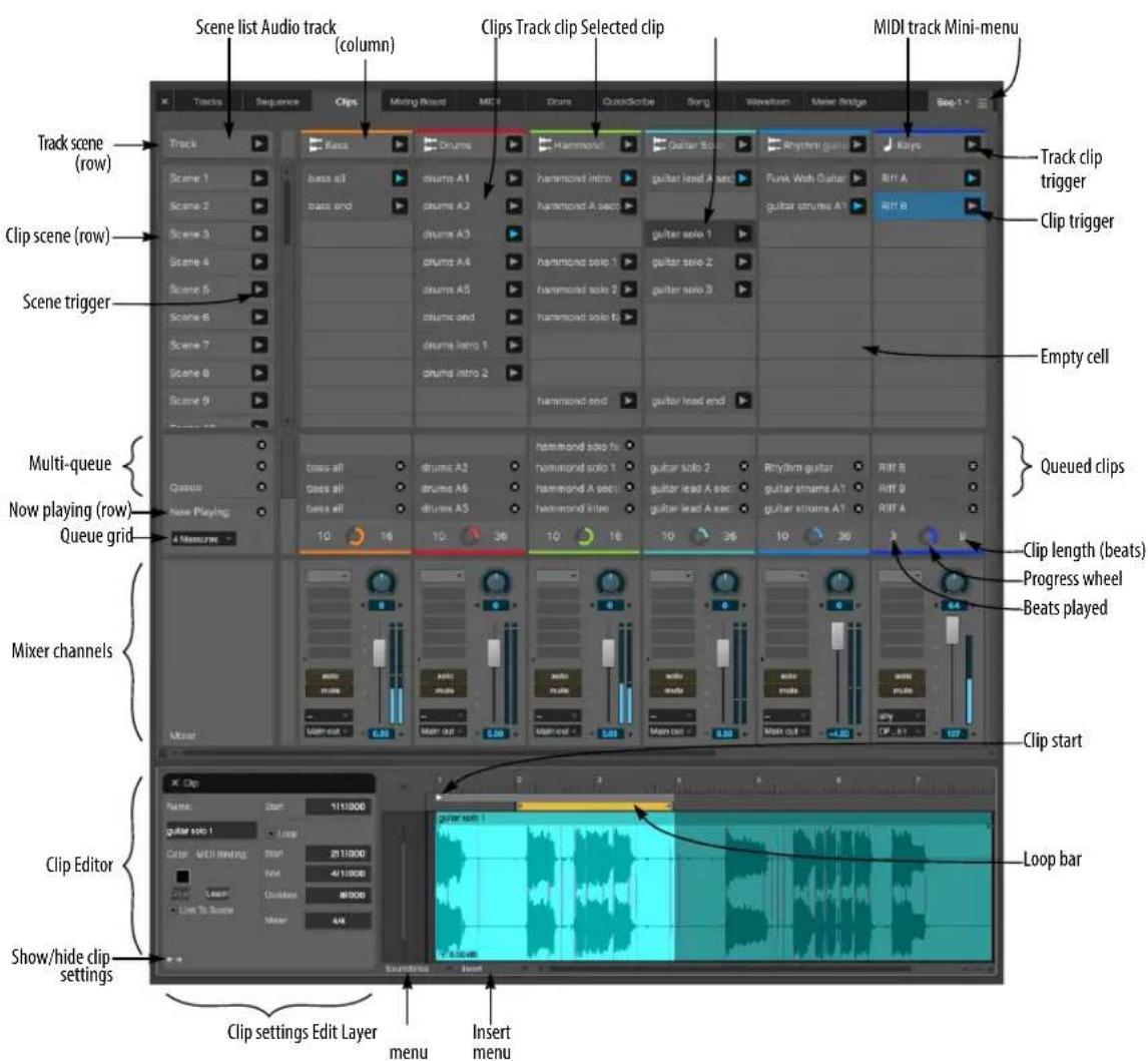
Figure 30-1: The Clips window.
Track clip trigger: Click to play or queue the clip. The clip drops to the Now Playing row or Multi-queue section at the bottom of the column.
Selected clip: Select a clip to view it in the Clip Editor. You can also cut, copy and delete it.
Scene list: A scene consists of an entire row of cells. Each row represents a different scene.
Scene trigger: Click to queue or play the scene (row). All the clips in the row drop to the Now Playing row or Multi-queue section at the bottom of the column.
Clip scene (row): A scene consisting of any clips present in the row. Click the scene trigger to play or queue the scene.
Track scene (row): A scene consisting entirely of track clips (in the top row). Click the scene trigger to play or queue the scene.
Multi-queue: Enable the Multi-queue from the Clips window mini-menu. When enabled, you can cue any number of clips, in the queue, where they then play consecutively.
Queue grid: Determines the interval at which queued clips begin to play, i.e. every 2 bars, 4 bars, 8 bars, etc.
Queued clips: When the Multi-queue is enabled, queued clips appear in stacked fashion here. When the cue empties, the last clip will loop continuously.
Now playing (row): Shows the clip currently playing in each track.
Clip length (in beats): The length of the current clip (in beats).
Progress wheel: Shows the playback progress of the current clip.
Beats played: The number of beats already played for the current clip.
Mixer channels: Displays basic Mixing Board settings for each track, including volume fader, pan, Solo, Mute, I/O assignments and inserts.
Clip Editor: Displays the contents of the selected clip. Lets you set basic parameters and edit the clip's audio or MIDI data.
Clip settings: Basic settings for the clip, including its name, start/end times, etc.
Show/hide clip settings: Shows or hides the clip settings section of the Clip Editor.
Edit layer menu: Access edit layers for clips here, just like the Sequence Editor.
Insert menu: Insert audio or MIDI data into the clip using this menu, just like the Insert menu in the Sequence Editor.
Clip start: Drag the Clip Start marker to graphically adjust the clip's start location.
Loop bar: If the clip's Loop option is enabled, drag the loop bar or its end points to adjust the loop graphically.
CLIPS WINDOW MINI-MENU
Play on Clip Queue: When enabled (checked), DP's main transports will begin playback when you trigger a clip. When unchecked, cuing clips does not start playback.
Auto End Clip Record: When recording into a clip, enable (check) this option if you would like the record pass to finish after the first time through the queue grid loop (four bars, for example). When disabled (unchecked), recording continues indefinitely for the entire duration of the record pass.
Show Clip Editor: Displays the Clip Editor (Figure 30-1) below the Clips window.
Enable Multi-Queue: Enables the Multi-queue (Figure 30-1). When enabled, you can stack any number of clips in the queue, where they then play consecutively.
Show Mixer: Shows or hides the mixer section at the bottom of the window (Figure 30-1).
Attach/Clear Mixer MIDI Controller: Lets you assign MIDI controller data to items in the Clips window mixer panels for hands-on mixing from your MIDI controller device.
MIDI Learn Mode: Puts the Clips window into a special mode where you can click active items to assign them to any incoming MIDI triggers, like keyboard keys, controller pads, MIDI pedals, etc.
Enable MIDI Bindings: Temporarily enables or disables any MIDI assignments you've made in MIDI Learn Mode.
WHAT IS A CLIP?
A clip is a container for a single track's worth of data. Think of it as a small slice of a track that you can manipulate as a single object.
Clips are typically one, two, four or eight bars long. However, they can be of any length, as short as one beat or as long as an entire song.
Clips can contain any combination of track data. For example, a MIDI clip can contain anything that goes in a MIDI track, such as notes and controller data. Audio clips can contain anything that goes in an audio track, including one or more soundbites, volume automation, plug-in automation, pitch and stretch layer edits, and so on.
Clips also have their own object settings, such as a clip name, color, duration and so on. These settings can be accessed and edited in the Clip Editor (see “Clip settings” on page 295).
Clips can reside in the Clips window and also in tracks. However, they are required to match the basic format of their track. MIDI clips can only go in MIDI tracks. Audio clips can only go in audio tracks. Further, mono audio clips can only go in mono audio tracks, stereo clips in stereo tracks, and so on.
Clips are independent objects. For example, if you duplicate a clip, the resulting duplicate is a new, completely different clip. It is not a ‘clone’ — or ‘instance’ — of the original clip. Therefore, if you make change in one, it will not be reflected in the other.
CLIPS VERSUS CLIPPINGS
Clips as described above are not the same as Clippings, as explained in chapter 55, “Clippings” (page 705). Clippings are much more broad in terms of what they can hold as data. For example, a clipping could consist of ten tracks worth of audio and MIDI data. A clip in the Clips window, however, can only consist of one track’s worth of data. That said, a clipping could certainly be dragged and dropped into the Clips window if it, too, consists of data compatible with the track it is being dropped into. Conversely, a clip can be made into a clipping, so if you use clippings in your work with Digital Performer, you could certainly use the clippings feature to manage Clips window clips.
OPENING THE CLIPS WINDOW
To open the Clips window, choose Project menu > Clips. You can also simply click the Clips tab in the Consolidated clips Window.
CLIPS WINDOW BASICS
The Clips window displays tracks in the current sequence as columns with cells that hold clips (Figure 30-1 on page 288). Clips can be dragged and dropped into cells from the Content Browser, Soundbites window, Sequence Editor, Tracks Overview and other edit windows. Clip data can also be copied from other windows and pasted into a cell, or recorded directly into a cell. Within a track (column), clips can be arranged however you want in the cells; their order top to bottom doesn't matter (except for arranging scenes, as explained later).
Each clip has a trigger (play) button (Figure 30-1). Clicking it causes the clip to be queued for playback, either before or while Digital Performer is playing back. Once queued, clips initiate playback according to the queue grid setting at the time they are triggered (Figure 30-1). The Queue grid is adjustable and typically set to 2 bars, 4 bars, 8 bars, etc. For example, if the queue grid is set to 4 bars, newly queued clips will begin to play on the downbeat of bars 1, 5, 9, 13, 17, 21, etc. The queue grid only affects clips at the time they are triggered; clips that have already been triggered are not affected if you change it.
As explained earlier, clips consist of audio or MIDI data compatible with their corresponding track type. If you try to put a MIDI clip into a mono audio track, for example, it won't play; accordingly, it will have no trigger button (as shown in Figure 30-3 on page 293).
THE TRACK STRETCH SETTING
Before you begin using the Clips window, it is a good idea to enable the Stretch setting for any audio tracks you'll be using in the Clips window. This ensures that your clips will play in time with the time line and each other. See “Stretch” on page 149.
SHOWING, HIDING AND ARRANGING TRACK COLUMNS
Use the Track Selector to show and hide tracks in the Clips window.
Tracks are ordered left to right according to their position in the Track List and Sequence Editor, top to bottom. To rearrange the track columns, reorder the tracks in the Track List (“The move handle” on page 176) or Sequence Editor (“Moving tracks up or down” on page 377).
TRACK TYPES
You can use any type of track in the Clips window (“Basic track types” on page 125). Most often, you’ll be using MIDI tracks, and mono and stereo audio tracks. However, you can also include instrument tracks, aux tracks, VCA tracks or even Master Fader tracks, for the purposes of triggering mix automation data.
TRACK PLAYBACK VERSUS CLIP PLAYBACK
Once clips have been placed in the cells of a track, they aren't actually "in" the track. In other words, they exist independently of any material in the track, as viewed in the Tracks Overview, Sequence Editor or other edit windows. Accordingly, they won't play until you trigger them with their trigger buttons. Until you do, you'll hear whatever material is in the track. As soon as you trigger the clip, it "takes over" the track's playback. So at any given time, you will only hear either the clip or the track material, but not both. Similarly, only one clip can play at a time within a track. So, if you have clips that you intend to play consecutively, you can place them in the same track. For clips that you might want to play simultaneously, place them in separate tracks.
The top row of clips are an exception: see "Track clips" below.
CREATING CLIPS
To create a clip, you can:
■ place existing material into a cell in the grid
■ create a new, empty clip and use the Clip Editor to construct new material
■ record directly into a new, empty clip
■ record into an existing clip
When placing existing material in a cell, it must be compatible with the track format (MIDI, mono audio, stereo audio, etc.)
Drag and drop
Drag and drop items from other windows (the Soundbites list, Content Browser, Sequence Editor, etc.) into any compatible cell. If the cell is already occupied by a clip, the existing clip is replaced.
Copy and paste
To create a clip using copy and paste:
1 Copy material from any single track in the Tracks Overview, Sequence Editor or any other editor.
You can do so from an object selection or a time-range selection.
2 Select a cell in the Clips window and paste. Be sure the cell belongs to a track that is compatible with the data you've copied (MIDI, mono audio, stereo audio, etc.)
A new clip is created from the material on the clipboard. If the cell is already occupied by a clip, the existing clip is replaced.
Create a new, empty clip
1 Right-click an empty cell and choose New Clip from the menu.
2 Use the Clip Editor to build the clip's content. See "The Clip Editor" on page 295.
Record into an empty clip
To record into an empty audio or MIDI clip:
1 Disable the Play on Clip Queue option in the Clips window mini-menu (page 289).
Otherwise, recording will begin as soon as you click the cell's record button (Figure 30-2).
2 Record-enable the track (Figure 30-7 on page 295).
Each empty cell in the track now displays a record button.

Figure 30-2: Recording into an empty clip cell.
3 Click the cell's record button to record-arm the cell.
4 Set the Queue Grid for the desired duration of the clip you wish to record (such as two bars).
5 Start recording.
Recording occurs the first time through the loop (for duration you set for the queue grid, such as two bars). Then the clip drops into the queue and starts looping.
Record into an existing clip
To record into an existing clip, follow the same procedure as above, except for the following two additional steps after Step 2:
■ Option/Alt-click the Record button (Figure 30-11 on page 297) to engage Clip Record mode. This gives existing clips a record button, similar to what is shown in Figure 30-2.
■ If you are recording into a MIDI clip and wish to overdub record over the existing material in the clip, enable Overdub Record mode (page 211).
While recording in Clip Record mode, the clip is also recorded into its respective track. The same goes for any existing clips that you trigger in the Clips window: they are also recorded into their respective tracks, even if those tracks are not record-enabled. See “Recording triggered clips to tracks” on page 297. Be careful if there is existing material in the tracks that you wish to preserve; if so, don’t trigger any other clips while recording into an existing clip.
THE TRIGGER BUTTON
To trigger a clip, click its trigger button (Figure 30-1 on page 288).
If the trigger button is missing from a clip, it means that the clip is not compatible with the track. For example, if you place a MIDI clip in an audio track cell, its trigger button will disappear to indicate that it cannot be played.
While a clip is playing, its trigger button is shaded blue. When not playing, it is gray.

Figure 30-3: Clips.
TRACK CLIPS
Track clips are displayed across the very top of the Clips window grid, in the top row. These track clips are "hard-coded" to represent material in the track itself. When a track clip plays, you will hear any audio or MIDI data in the track at that moment (i.e. the main counter location). Because track clips exclusively represent time line material in the track, they cannot be pasted into, and the clip menu (Figure 30-4) is not available.
CLIP MENU
Right-click a clip to open the Clip menu.

Figure 30-4: Right-click to open the Clip menu.
Rename Clip: Lets you rename the clip.
Link Clip to Scene: Links or unlinks the clip to its corresponding scene. When linked, it will get triggered with the scene. When unlinked, it won't.
Set Clip Color: Brings up the standard color picker with eye dropper, allowing you to set the clip's color.
Clear Clip Color: Reverts the clip color to black.
Insert Scene Above/Below: Inserts a new, empty scene (row) above or below the row you've right-clicked.
Delete Scene: Removes the scene (row) that you've right-clicked.
Cut/Copy/Paste: Cuts, copies or pastes into the contents of the cell.
Erase: Empties the cell without affecting the clipboard.
Learn MIDI Binding: Lets you to assign a MIDI command to the clip, as indicated in the Clip Editor.
SCENES
A scene is an entire row of cells in the Clips window (Figure 30-1 on page 288). Each row represents a different scene. When you trigger a scene using the scene trigger button (Figure 30-1), the entire row of clips is queued for playback. A typical use of scenes is for different sections of a song, such as the intro, chorus, verse, bridge, solo section, etc. However, you can structure and use scenes however you want.
THE TRACK SCENE
The track scene (Figure 30-1 on page 288) triggers track time line playback for all tracks in the Clips window, as explained earlier in “Track clips” on page 293).
PLAYING CLIPS AND SCENES
When you trigger clips or scenes, they “drop” into the Now Playing row (Figure 30-5) and either begin playing, or they are queued to begin playing at the next queue grid boundary. The clip continues to loop until you either cancel it or trigger another clip (unless it’s a one-shot clip, as explained later in this chapter).

Figure 30-5: The 'Now Playing' row.
For example, in Figure 30-5, the queue grid is set to 2 measures. If you trigger a clip or scene at 5|3|000, it will be queued to begin playing at the next two-bar downbeat, which would be 7|1|000.
Queue grid boundaries are measured from the beginning of the sequence. So, if you set the queue grid to 4 measures, the queue grid boundaries occur at the downbeats of bars 1, 5, 9, 13, 17, 21, 25, etc., When you then trigger a clip or scene, it plays at the next grid boundary.
To cancel a clip, or all currently playing clips, click the cancel buttons shown in Figure 30-5.
THE MULTI-QUEUE
When the multi-queue is enabled in the Clips window mini-menu, the multi-queue appears above the Now Playing row (Figure 30-6). When you then trigger clips or scenes, they get stacked in the queue, each playing consecutively until the final clip makes it to the Now Playing row, where it will loop indefinitely until you either cancel it or trigger another clip.
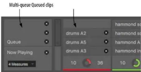
Figure 30-6: The multi-queue.
When queued clips play consecutively, they play as follows, depending on their length and the size of the queue grid:
If... Then...
The clip is shorter than the queueIt loops until the next queue grid grid boundary.
The clip is the same duration as It plays once through. the queue grid
The clip is longer than the queue It plays partially, stopping at the grid next queue grid boundary.
For example, if you had an 8-bar grid and you queued a 1-bar drum loop, followed by a 4-bar drum loop and then an 8-bar drum loop, the 1-bar drum loop would play eight times, the 4-bar loop would play twice and then the 8-bar loop would play all the way through, indefinitely (since it's the last one queued).
This is really useful, for example, when you have eight bar bass and rhythm lines but you want to use 2-bar drum loops with them.
Once clips are queued, you can't rearrange their order, but you can cancel them, regardless of where they are in the queue stack.
MIXER CHANNELS
Use Show Mixer in the Clips window mini-menu to show or hide the mixer channels (Figure 30-1 on page 288). These mix settings are the same as described for the Mixing Board. See chapter 70, "Mixing Board" (page 821).

Figure 30-7: Mixer channel.
THE CLIP EDITOR
Use Show Clip Editor in the Clips window mini-menu to show or hide the Clip Editor (Figure 30-1 on page 288). The Clip Editor lets you view the contents of a clip, along with basic clip settings such as its name, length, etc.
Clip settings
Each clip has the following clip settings:
Name
■ Color
■ MIDI binding
■ Link clip to Scene
■ Start time
■ Loop enable
■ Loop start
■ Loop end
■ Loop Duration
■ Meter

Figure 30-8: Clip settings.
Color
Each clip can be assigned a color to help you organize clips visually by color. Click the color swatch to open the standard color picker, which includes the eyedropper for copying other colors on your screen.
MIDI binding
Click Learn to assign the clip to a MIDI command. When you send that MIDI command, doing so triggers the clip. Also see “MIDI Learn Mode” on page 297.
Link Clip to Scene
When checked, the clip is linked to its corresponding scene. When linked, it will get triggered with the scene. When unlinked, it won't.
Start
The Start time (Figure 30-8) lets you determine where the Clip will start playing, relative to the data it contains. You can also adjust this setting graphically, as shown in Figure 30-9.
Loop (versus one-shot)
When Loop is checked, the clip loops indefinitely until you either cancel it or trigger another clip. When Loop is unchecked, the clip will play as a one-shot clip (once through only).
Loop Start time/End/Duration
Use the Loop Start/End/Duration times to determine when the clip starts and stops looping. You can set these values wherever you want in the clip. You can also edit them graphically using the loop points in the clip editor time ruler (Figure 30-9).
Meter
Enter the desired meter for the clip.
Clip Editor
The Clip Editor works the same way as the equivalent features found in the Sequence Editor (chapter 38, “Sequence Editor” (page 371). Here, you can edit audio data, MIDI data, automation, pitch, stretch and so on.
The area above the time ruler displays useful information, similar to other editors. See "Information Bar" on page 367.
The Start Time strip works similarly to the Loop strip: drag the start time marker to change it. If you hold down the shift key while dragging the start time handle, the loop start handle or either bar, both move together. As another shortcut, click the start time handle or the loop boundary handles to make a time range selection.
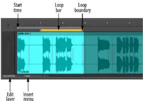
Figure 30-9: Clip Editor for an audio clip.
For MIDI tracks, the clip editor works like MIDI track editing in the Sequence Editor (chapter 38, "Sequence Editor" (page 371)).
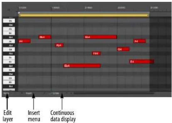
Figure 30-10: Clip Editor for a MIDI clip.
CLIP RECORD MODE
Option/Alt-click the Record button to toggle between Record mode and Clip Record mode.

Figure 30-11: Option/Alt-click the Record button to toggle between Record mode and Clip Record mode.
In Clip Record mode, two things happen:
■ Clips that are triggered in the Clips window are recorded into their respective tracks.
- Existing clips in the Clips window can be recorded into (see “Record into an existing clip” on page 292).
Recording triggered clips to tracks
Clip Record mode allows you to capture your performance as you trigger clips in the Clips window. You do not need to record-enable any tracks beforehand. With Clip Record mode enabled (as shown in Figure 30-11), simply click the Clip Record button (in Figure 30-11) to start recording. Any clips you trigger are placed in their respective track at the current counter location. If they repeat, they are looped within the track for as long as they remain looping. (For more information about looping clips in tracks, see "Looping a clip" on page 402.)
When using Clip Record mode, you do not need to record-enable each track. Any clip that is triggered is recorded.
Be mindful when using Clip Record. Every triggered clip is recorded, covering up any material already in the track. For details about editing clips, especially layered ones, see "Clip layering" on page 401.
MIDI LEARN MODE
Choose MIDI Learn Mode from the Clips window mini-menu to put the window into a mode where you can assign MIDI bindings to items in the window, to be able to trigger them from a MIDI controller (Figure 30-12). Assignable items appear in gray against a darkened background. The currently active item flashes blue, and its MIDI settings are displayed in the pane below the window, as shown.
Making assignments
To make an assignment click the item you wish to assign. Alternately, you can use the tab key to move to different sections of the window, and then use the arrow keys to navigate through the eligible items in that section to choose the desired active item. Once active, send the MIDI data from your MIDI controller and it appears in the pane below.
Learn channel/source
When making MIDI bindings, use the Learn Channel and Learn Source check box options to remember the specific MIDI channel or even MIDI source for the MIDI binding. This can be
very useful when you are using multiple MIDI devices to trigger clips and other items in the Clips window.
Choose Attach Mixer MIDI Controller from the Clips window mini-menu to assign a MIDI controller to any item in the Clips window Mixer panel for remote control from any MIDI device. Use the Clear Mixer MIDI Controller command to remove the assignment. You can also access these commands by right-clicking a mixer item. This works the same way as the Mixing Board. See "Remote control" on page 844.

Figure 30-12: MIDI Learn mode in the Clips window.
CHAPTER 31 POLAR
OVERVIEW
The POLAR window is a self-contained audio recording module within the general environment of Digital Performer. What makes POLAR different from Digital Performer's usual audio track-based recording is this: POLAR records your audio entirely into RAM, rather than writing it to a hard disk. Because RAM is so much faster, it allows Digital Performer to be much more interactive with you during recording, allowing you to immediately loop newly recorded material, overdub (merge) new audio data with existing audio, and otherwise respond instantaneously to your actions.
A typical POLAR session....300
Ideas for using POLAR....301
Preparations for using POLAR 301
Opening the POLAR window 302
Memory used 302
Ways to free up RAM for POLAR recording .... 302
Setting the length of each pass....302
Choosing an input and setting input level .... 303
Processing POLAR input with effects 303
Recording multiple channels into POLAR....303
Choosing an output 303
Controlling POLAR's output volume 304
Effects processing on output 304
Monitoring POLAR's live audio input 304
The current pass ....304
Adjusting levels and panning 305
Playback and transport control....305
Punching in and out....305
Creating new passes 305
The record gate settings....306
Viewing previous passes 306
Working with passes in the pass list 306
Working with pass groups....306
Exporting a POLAR session....307
Saving and loading POLAR sessions 308
Remote control of the POLAR window....308
A TYPICAL POLAR SESSION
A typical POLAR session might go as follows: you import a 4-measure drum loop, place it in a regular audio track in the Tracks window and set up the memory cycle points around it so you can loop-record over it in the POLAR window.
You open POLAR and record a bass line over the drum loop. You like it, but you want to try again to see if you can lay down something a little better. You start playing another bass line and as soon as you start playing, POLAR automatically mutes the first pass for you (so it doesn't interfere with your new pass). You then record several more takes, automatically muting each previous pass as you begin recording a new one. Each take is stored as its own "pass" in the list at the bottom of the window, as shown in Figure 31-1. After choosing the bass line you like the best (by muting all the other passes), you proceed to some layered percussion. This time, you use POLAR's overdub recording capabilities, recording each percussion instrument into the same pass. The result is one pass with all of the percussion parts in it.
Using these same techniques, you add rhythm guitar and a lead guitar solo on top, mixing as you go with the mute, volume and pan controls for each pass.
When you're done, you click the Export button in the POLAR window, which writes the session to disk as audio files and adds the session to the sequence as a single hard disk track right below the drum loop you started with. (Or, if you prefer, you can export each pass as its own separate
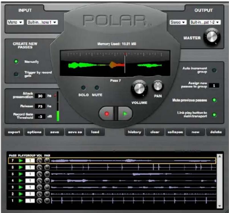
Figure 31-1: The POLAR window.
track.) Finally, you click the Save button in the POLAR window to save the entire POLAR session as its own document. This allows you to go back to the POLAR session at any time —exactly as you saved it — for further tweaking, layering, or other modifications.
RAM-based loop recording
The scenario above is just an example. Generally speaking, POLAR is ideal for any recording situation that calls for recording multiple passes of material, and either layering the passes on top of one another or recording each pass individually, storing each pass as a “take” that gets muted as you begin a new take.
Recording in context
One of the best things about POLAR is that you can play the rest of your sequence — both MIDI and audio — while recording into it.
Saving your POLAR session
When you're done recording into POLAR, you can export your RAM-based audio as hard disk audio — and even automatically create tracks, right along side your current MIDI and audio tracks — to save them with the rest of your Digital Performer project. Or you can save your POLAR session as its own document. You can even do both, so that you can always go back to the original POLAR session for further modification.
IDEAS FOR USING POLAR
Here are a few ideas for how you can use POLAR:
■ For years, Digital Performer has allowed you to build MIDI drum loops by overdub recording into a MIDI track. Now you can do this sort of thing with audio in the POLAR window!
- Remember the EchoPlex™? For those of you that don't, it was a device introduced in the 70's that let you record a short phrase and then build on top of it. POLAR is ideal for building this type of layered effect.
■ POLAR is also ideal for recording multiple takes of the same material, such as multiple takes for solos, etc.
■ How about writing entire sections of music? As long as you have enough RAM, you can build entire sections of music, interactively, in real time.
PREPARATIONS FOR USING POLAR
The following sections cover the specific features in the POLAR window.
Listening to existing audio and MIDI tracks while recording in POLAR
POLAR lets you record either with or without listening to existing MIDI and/or audio tracks.
If you don't want to hear any sequence tracks while recording in POLAR, the easiest way to keep them from playing is to turn off the Link play button to main transport button in the POLAR window. For details, see “Playback and transport control” on page 305.
If you do want to listen to sequence tracks, leave this button turned on so that when you start POLAR, the sequence will start, too. Often, you'll want to loop a specific section of the sequence while recording in POLAR. To do so, turn on Memory Cycle and set the cycle points accordingly. This will make the sequence loop that section of music while you're recording in POLAR.
Keep in mind, however, that you don't necessarily have to loop the sequence while recording a POLAR session. For example, you could (if you wanted to) play a 10-minute sequence from start to finish while layering 8-measure loops in POLAR.
Establishing a tempo reference
If you're listening to existing material while recording into POLAR, then you're all set to record at the tempo of the sequence.
If you don't have any existing material to listen to, but you want your POLAR material to match the tempo of the sequence, you might want to set up Digital Performer's metronome click as a reference for your first pass in POLAR. After you've recorded the first pass, you can turn off the click.
Recording without a tempo reference
Of course, there's no rule that says you have to record at the sequence's tempo. You can record into POLAR with no tempo reference at all if you want and then just build on your first pass — although you might find it a bit difficult to anticipate the end of the loop when doing this sort of “free-form” recording. Therefore, for free-form recording like this, you might find it easier to give yourself a loop length that is 5 or 10 seconds longer than what you intend to record so that you can give yourself some blank time at the beginning and end of each pass.
OPENING THE POLAR WINDOW
Choose POLAR from the Studio menu.
MEMORY USED
POLAR records audio into RAM instead of writing it to your hard disk. It uses memory in your computer that it not being used by the system, Digital Performer, MAS, or any other currently running applications. The memory used display shows you how much RAM is currently being used by POLAR.
The maximum number of passes you can record in POLAR is determined by how much RAM is available in your computer and how long the loop is that you are currently recording into.
WAYS TO FREE UP RAM FOR POLAR RECORDING
You can give yourself more passes by freeing up as much RAM as possible before using POLAR. Here are a few ways to free up RAM:
■ Quit all other applications while you are running Digital Performer.
■ Purchase more RAM for your computer. RAM is affordable these days (compared to the cost of your computer). The more you have, the more flexibility you have when using POLAR (e.g. you will be able to record longer passes, more passes, etc.)
SETTING THE LENGTH OF EACH PASS
POLAR is a loop recording environment.
Therefore, each pass has a fixed length, which it continuously (and seamlessly) loops as you record into the pass and then play it. The length of each pass is determined by the current Memory Cycle points (Figure 22-16 on page 207) at the moment when the pass is first created. So before you create a pass, set the Memory Cycle points as desired to determine the length of the pass. After a pass is created, its length cannot be changed. (But don't worry. The POLAR window is very flexible, and there are other things you can do. For example, you can collapse a pass with passes of other lengths. More on this later.)
Each pass can be any length you want. Even within the same POLAR session, you can create passes of any length. For example, you might start with an 8-measure pass, and then record a 2-measure pass. The 2-measure pass simply loops continuously over the 8-measure pass, which itself loops continuously. You could then add a 1-measure pass and even a 3- or 7-measure pass. Even though they have odd lengths that don't match, they all continuously loop against each other.
Getting creative with passes of different lengths
By using passes with odd lengths — especially ones that don't land on measure or beat boundaries — you can create loop “collages” that sound somewhat repetitive but also sound like they are continuously evolving. For example, you might try a pass that is 14 and half beats against
one that is 5 and three quarters of a beat long. When you add 5 or 6 layers with lengths that don't match, you can end up with some very interesting results.
Setting the length of the first pass
When you first open the POLAR window, it opens empty, with no passes. As soon as you press the record button, the first pass is created. So be sure to set the Memory Cycle points before you begin recording (or before you click the new button, if you're using it to create the first pass) so the first pass is the length you want.
CHOOSING AN INPUT AND SETTING INPUT LEVEL
Use the INPUT section of the POLAR window to choose the input you would like to record from. The input menu shows all of the inputs provided by your audio hardware; these are the same inputs that are available to regular audio tracks in the Tracks window.
You can switch the input at any time during POLAR recording.
Input level is determined by your audio hardware, just like it is for a regular audio track.
PROCESSING POLAR INPUT WITH EFFECTS
Notice that the input menu lets you choose a bus (or bus pair) as an input. This allows you to process the live input going into POLAR with real-time effects plug-ins in Digital Performer's Mixing Board. Here's how:
1 Create an audio track or aux track.
2 For the track's input, choose the input from which you'll be feeding POLAR your live audio material.
3 For its output, choose a bus (or bus pair).
4 In the Mixing Board, choose whatever plug-ins you would like from the track's five plug-in inserts. For example, you might use echo and PreAmp-1 fuzz on a live guitar input.
5 In the POLAR window, choose the same bus from the input menu.
When applying effects to input in this manner, the effects will be recorded as part of the signal in POLAR, so you won't be able to remove or modify them later on. If you'd like to have that flexibility, do your processing on output instead (discussed shortly).
RECORDING MULTIPLE CHANNELS INTO POLAR
If you need to record multiple channels of audio into POLAR, the way you set this up depends on whether or not you'll be recording them simultaneously.
If you are recording several live inputs simultaneously, you'll need to create a separate track with the appropriate input for each one and then bus them all to POLAR on the same bus. For example, you could assign all of their outputs to bus 1-2 and then choose bus 1-2 from POLAR's input menu.
Notice that this technique allows you to apply different effects processing to each input in the Mixing Board.
If you are going to record several inputs one at a time (not at the same time), you can set them up as just described above, or you can set up each one on its own input and then just switch inputs on the fly in POLAR during recording.
CHOOSING AN OUTPUT
Use the OUTPUT section of the POLAR window to choose the output you would like to send POLAR's master stereo output mix. The output menu shows all of the outputs provided by your
audio hardware; these are the same outputs that are available to regular audio tracks in the Tracks window.
You can switch the output at any time during POLAR recording.
CONTROLLING POLAR'S OUTPUT VOLUME
The Master volume knob in the Output section of the POLAR window controls POLAR's overall output level. It only affects material that has already been recorded into POLAR. It does not affect live input that is currently being patched through.
EFFECTS PROCESSING ON OUTPUT
Earlier, we discussed how you can process live input being recorded into POLAR. This is fine, as long as you know that you want to make the effect permanent. If you want to process what you are recording in POLAR, but you want the processing to be real-time so that you can bypass or modify it later on, you'll need to process the live input at the output stage. There are several ways to do this. One way is to choose an output pair in POLAR and then set up a master fader assigned to that same pair in the Mixing Board. Then, you can place any plug-in effects you want on the master fader. You'll hear them during recording, but the actual audio material you are recording into POLAR will be dry. You can then process it however you like later on. If you would like to hear different effects on different passes during your session, you could either change them on the fly as you go, or set up different output channels and master faders for each set of effects beforehand.
MONITORING POLAR'S LIVE AUDIO INPUT
As soon as you open the POLAR window, it activates the input currently selected in the INPUT section of the window. Monitoring this input works just like record-enabling an audio track with the same input. Therefore, the procedure for monitoring POLAR input is the same as monitoring input for a record-enabled track. Be sure that Audio Patch Thru is not set to "Off" in the Studio menu, and choose the appropriate channel pair from the output menu. If necessary, set the buffer size in your audio hardware driver accordingly to reduce patch through latency. See "Audio monitoring latency" on page 242.
THE CURRENT PASS
The main waveform display in the POLAR window shows the current pass you are recording into. This pass is also displayed at the top of the pass list in the POLAR window (more on this later). POLAR always records into the current pass. You can cycle through the current pass multiple times, overdubbing into it as many times as you like, or you can set up POLAR to automatically create a new pass each time you begin playing new material (each time you trigger the record gate — more on this later).

Figure 31-2: The main waveform display in the POLAR window shows the current pass — the one you are currently recording into.
As soon as you start playback, you'll see a wiper to indicate current playback position. If POLAR's Link play button to main transport button is enabled, this wiper also corresponds with the main wiper in Digital Performer's Tracks window.
During playback, the wiper leaves a blue trail behind it to indicate that no recording is going on. As soon as you click POLAR's record button, the
trail turns red to give you a clear visual indication that you are now recording. You can punch in an out as many times as you like at any time.
Right below the waveform display, POLAR displays the current pass by name. You can look at previously recorded passes at any time by clicking on them in the pass list.
ADJUSTING LEVELS AND PANNING
Each pass, including the current pass, has its own volume and pan control. Unity gain equals the level at which the pass was originally recorded (as determined by your input level at the time it was recorded). You can tweak the volume and pan of the current pass either with the big knobs in the current pass section (Figure 31-2) or with the smaller knobs next to it in the pass list at the bottom of the window.
PLAYBACK AND TRANSPORT CONTROL
In general, you should think of POLAR's transport control as being pretty much independent of Digital Performer's main transports — with the exception of the Play button.
If POLAR's Link play button to main transport button is turned off, POLAR's transport is completely independent of Digital Performer's main transport.
If the Link play button to main transport button is turned on, then starting playback from either transport (POLAR's or Digital Performer's main transport) will start playback. The primary purpose of this feature is when you are listening to tracks in the Tracks window during POLAR recording.
POLAR's record button is completely independent of the record button in the main transport. For example, the [3] key on the numeric keypad does not toggle POLAR's record button — only the record button in the main transports. (POLAR can, however, be driven using keyboard shortcuts, and you can customize the shortcut assignments. See “Remote control of the POLAR window” on page 308.)
You can actually record material into a hard disk track and the POLAR window at the same time, although there's no reason to ever do this, since you can export POLAR material as an audio track at any time (more on this later).
PUNCHING IN AND OUT
You can punch in and out freely using the (red) record button in the POLAR window as many times as you like, whenever you like.
CREATING NEW PASSES
During POLAR recording, there are several ways to create a new pass. In the Create New Passes section of the window, there are two buttons as shown below.

Figure 31-3: New passes can be created manually or automatically with the record gate.
If you are creating new passes manually, the only way to create a new pass is to click the New button (or trigger it by remote control).
If you choose the Trigger by record gate option, then POLAR will automatically create a new pass every time you trigger the gate with your live audio input. With the record gate settings properly adjusted, as soon as you begin playing, POLAR
begins recording into a new take. This option is ideal for creating new passes on the fly — in the heat of the creative moment.
Attack preservation: This is the amount of material (in hundredths of seconds - hs) that POLAR preserves (includes in the recording) just before the instant that the record gate is triggered. If you are using the record gate, and the material you are recording sounds clipped off at the beginning, try increasing this setting.
Release: This setting controls the release (in hundredths of seconds - hs) of the record gate. Lower settings cause it to stop recording almost immediately after your input signal falls below the threshold. Higher settings will give you more time before it stops recording. If you are using the record gate, and you find that POLAR creates new passes too readily (you get too many new passes), try increasing this setting.
Record Gate Threshold: This is the input level that triggers the record gate. When the signal goes above this level, POLAR starts recording. Experiment with your input to achieve the best threshold setting for your input signal.
Automatically muting the previous pass
If you like, POLAR can automatically mute the previous pass whenever a new pass is created. Just turn on the Mute previous passes button. This feature is ideal for recording multiple “takes” of the same thing, such as a guitar solo or bass line.
VIEWING PREVIOUS PASSES
You can view any pass in the main waveform display at any time by simply clicking on it in the pass list at the bottom of the window. Doing so selects the pass and displays it in the current pass section of the POLAR window.
WORKING WITH PASSES IN THE PASS LIST
The list at the bottom of the POLAR window shows all of the previous passes that have been recorded during the current POLAR session. In this area of the window, you can mute, unmute, attenuate and pan each pass. It also lets you reassign a pass to a different group. (More on groups in the next section.) The table below discusses several other capabilities in the pass list:
To do this Do this
| Select a pass Click its waveform | |
| Delete a pass Select it and click the delete button | |
| Select several passes Shift-click or command-click the waveform of each one | |
| Delete several passes Select them & click the delete button | |
| Collapse several passes into one | Select them and click the Collapse button |
Delete all passes Click the clear button
WORKING WITH PASS GROUPS
Passes can be grouped. As a group, they can be muted, unmuted, attenuated, panned, collapsed, exported and deleted together as a group.
Each group is identified by its number, starting with Group 1.
Use Assign new passes to group ____ to assign passes to each group on the fly. If you would like to assign each new pass consecutively to a new group, turn on the Auto increment group button.
To reassign a pass to a different group, type in the desired group number in the group column in the pass list.
To mute, unmute, attenuate, pan, collapse, or delete an entire group, use the remote controls. See “Remote control of the POLAR window” on page 308.
EXPORTING A POLAR SESSION
At any time during your POLAR session, you can export any combination of passes to disk. Exporting takes the audio that POLAR has recorded into RAM and writes it to your hard drive as an audio file. If you want, you can also cause the export operation to create audio tracks in the Tracks window that correspond with each pass that you're exporting — or it can create a single track with a bounced mix of the passes you're exporting.
Exporting is not the only way to permanently save your POLAR session work. See “Saving and loading POLAR sessions” on page 308.
POLAR Export Options
To control what happens when you export, click the options button to open the Export Options dialog.

Figure 31-4: The export options.
Channels: You can choose Mono, Stereo, or Best Fit. Best Fit means that the export command will make the best choice (mono or stereo) based on the material being exported.
Import: This is where you choose what the export operation does with the audio. If you choose Do not import, it will simply create audio files on your hard drive. If you choose Add to Soundbites Window, the audio files will be added to the bottom of the Soundbites window list. If you choose Add to tracks named "Polar", then tracks will be created in the Tracks window with the newly created soundbites accurately placed in them. The Create individual bites for each pass option determines whether you get a separate track for each pass or simply a single soundbite that is a mix of all the passes being exported.
File name: Type in the name for the audio files being created. If multiple audio files are being created, they will all have the name typed in this field, followed by a numbered suffix. For example, if you type “Polar Audio” in the File Name field, the various audio files will be named “Polar Audio-1”, “Polar Audio-2”, and so on.
Create individual bites for each pass: When this option is unchecked, exporting will collapse all of the passes being exported into one audio file, either mono or stereo, depending on what you chose for the Channels setting above.
When this option is checked, exporting will create a separate audio file for each pass. If you're adding them to the Tracks window, too, a separate track will be created for each pass.
Use volume and pan settings: When this option is checked, each pass is written to disk with the volume and pan settings currently shown in the pass list. If you want to “get exactly what you hear”, check this box. If you want to export each pass exactly as it was recorded, with no alterations due to POLAR mixing, uncheck this option.
Only export selected passes: Select passes by Command/Ctrl-clicking their waveform in the pass list at the bottom of the POLAR window.
Destination folder: Choose where you want the newly created audio files to be placed on your hard drive.
SAVING AND LOADING POLAR SESSIONS
In addition to exporting, the POLAR window also has the ability to save your POLAR session as its own POLAR document on your hard drive. This lets you reopen the session at any time and restore it into RAM exactly in the same state as when you saved it. For example, you might record a fairly elaborate POLAR session, export just a stereo mix of it in your sequence as an audio track (for simplicity), and then save the POLAR session separately so that you can go back to it at any time to make modifications or additions. Between exporting and saving, the POLAR window gives you all the flexibility you need in saving your POLAR sessions.
POLAR session files are saved and opened as separate documents on your hard drive using the buttons in the POLAR window.
REMOTE CONTROL OF THE POLAR WINDOW
POLAR is optimized for live, interactive recording with the computer. Therefore, all of its features can be used by MIDI remote control, so that you can sit in front of your instrument (or microphone or whatever) and make music without having to reach over to the computer. To set up remote controls, go to the Commands window in the Setup menu. The following table explains each POLAR command.
POLAR remote What it does/ how to use it
| Toggle Play Toggles POLAR's play button. | |
| Toggle Record Toggles POLAR's record button. | |
| Clear Passes Deletes all passes, including the current one.This is the same as clicking the Clear button. | |
| Export Passes Exports as determined by the current Export options. This is the same as clicking the Export button. | |
| Collapse Passes Merges all of the currently selected passes into one pass. This is the same as clicking the Collapse button. | |
| New Pass Creates a new pass. The same as clicking thenewbutton. | |
| Toggle Manual Pass Mode | Toggles between the two buttons in the Create New Passes section of the POLAR window: the Manually button and the Trigger by record gate button. |
| Toggle Mute Previous Passes | Toggles theMute Previous Passes button. |
| Toggle Transport Link | Toggles theLink play button to main transport button. |
| Set Group Assign Opens a dialog that lets you type in a group number or play the group number from your MIDI controller. (See “Export Key Bindings” on page 108 to learn how to do this from your MIDI keyboard.) This changes the number in theAssign new passes to group box, and the current pass will be assigned to this group. | |
| Increment/ Decrement Group Assign | Raises or lowers the current group number in theAssign new passes to group box. |
| Toggle Auto Increment Group | Toggles the Auto increment group button. |
| New Pass in Group | Opens a dialog that lets you type in a group number or play the group number from your MIDI controller. (See “Numeric Base note” on page 107 to learn how to do this from your MIDI keyboard.) A new pass is created and assigned to the group. |
| Delete Passes In Group | Opens a dialog that lets you type in a group number or play the group number from your MIDI controller. (See “Numeric Base note” on page 107 to learn how to do this from your MIDI keyboard.) All of the passes in the group you specify will be deleted. |
| Export Passes In Group | Opens a dialog that lets you type in a group number or play the group number from your MIDI controller. (See “Numeric Base note” on page 107 to learn how to do this from your MIDI keyboard.) All of the passes in the group you specify will be exported (according to the current Export Options settings). |
| Collapse Passes In Group | Opens a dialog that lets you type in a group number or play the group number from your MIDI controller. (See “Numeric Base note” on page 107 to learn how to do this from your MIDI keyboard.) All of the passes in the group you specify will be collapsed into one pass. |
| Toggle Group Play Enable | Opens a dialog that lets you type in a group number or play the group number from your MIDI controller. (See “Numeric Base note” on page 107 to learn how to do this from your MIDI keyboard.) All of the passes in the group you specify will be muted (or unmuted). |
| Polar Group Louder/Softer (assign group) | Makes the current group louder or softer. The current group is the one whose number is currently displayed in the Assign new passes to group box To specify the group number, use the Set Group Assign remote before using this remote. |
| Group Pan Left/right (assign group) | Pans the current group hard left or hard right. The current group is the one whose number is currently displayed in the Assign new passes to group box. To specify the group number, use the Set Group Assign remote before using this remote. |
CHAPTER 32 Movie Window
OVERVIEW
Random access digital picture....311
Supported video formats....311
Opening movies....311
Closing movies....312
Movie control bar....313
The movie track ....313
Movie window mini-menu commands ....314
Scrubbing the Movie window ....315
Improving movie window performance .....315
External video hardware output....315
FireWire video output ....317
Streamers and other visual cues ....318
Exporting a Movie....318
RANDOM ACCESS DIGITAL PICTURE
Digital Performer's Movie Window provides synchronized playback of video clips with both MIDI and audio tracks in a sequence. Digital video provides random access to picture, just like digital audio and MIDI. For example, you can:
■ Instantly locate to any spot in the movie
■ Advance forwards or backwards one frame at a time through the picture and music
■ Scrub forward or backward (with or without audio and MIDI scrubbing)
■ Seamlessly loop both picture and music
■ Display streamers, punches and flutters superimposed on the Movie window image (see chapter 66, “Streamers, Punches and Flutters” (page 787)
All of this can be done without the hassles of slaving to external time code.
SUPPORTED VIDEO FORMATS
Generally speaking, Digital Performer can play any video file that is supported by your computer system. More specifically, if the video file plays successfully in macOS QuickTime Player or Windows Media Player, the it should work with Digital Performer as well.
OPENING MOVIES
Only one movie can be open at a time for a sequence. The Movie command in the Project menu opens a movie in Digital Performer. To open a movie for a sequence:
1 Play-enable a sequence in the Chunks window.
2 Choose Project menu> Movie to open a movie.
A standard file browser appears, allowing you to navigate to the movie file you wish to open. For a discussion of supported video formats, see “Supported video formats” above.
Working with multiple sequences
If you are working with multiple sequences, you can either use the same movie for all sequences, or use a different movie for each sequence. There is a checkable menu item in the Movie Window mini-menu called Use Same Movie for All Sequences. This menu item also appears in the movie track menu in the Sequence Editor. When it is checked, you get the following behavior:
■ Every sequence in the project uses the same movie.
■ Each sequence can have its own unique sequence start time, but the movie start time is the same for all sequences. Changing the sequence start time will make the movie begin earlier or later in the sequence.
■ The movie window is placed at the same position and size for every sequence.
■ Closing the movie window closes it for all sequences.
- Choosing a new movie for one sequence chooses that same movie for all sequences.
If you have two or more sequences in the project and you wish to open a separate movie for each sequence, uncheck the Use Same Movie for All Sequences mini-menu command and do the following:
1 Play-enable a sequence in the Chunks window.
2 Choose Project menu> Movie to open a movie for it.
3 Play-enable a different sequence in the Chunks window.
The movie window for the first sequence disappears at this point.
4 Choose Project menu> Movie to open a movie for the second sequence.
5 Repeat this procedure for as many sequences as you wish.
When you switch from one sequence to another (by clicking its play-enable button in the Chunks window), the movie window will update itself to show the movie you chose for that sequence. Each sequence also stores a separate location for the movie window on the screen. So you can reserve a different spot on screen for each movie. Or you can place them all in the same location, if you wish.
Displaying a blank movie for visual cues
You can open a blank movie (with a black background) by choosing Project menu> Movie, but then cancel the resulting dialog box. A blank movie can be used for any purpose, but it is especially useful for the purpose of providing a convenient, blank background for film score event visual cues, as shown below in Figure 32-1:
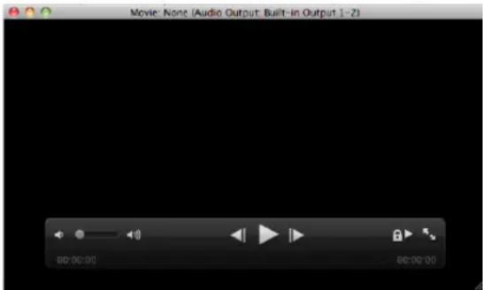
Figure 32-1: Creating a blank movie background for film score event visual cues.
CLOSING MOVIES
You may close the Movie window, and Digital Performer will still remember which movie file you opened at the time you last saved the project. To reopen the movie, just play-enable the same sequence choose Movie from the Project menu again. To close the movie permanently so that Digital Performer forgets about it, choose Clear Movie from the mini-menu.
If you have a movie open and want to choose a different movie, choose Open Movie from the mini-menu. Only one movie can open at a time for each sequence. (But each sequence can have its own movie, as explained earlier.)
MOVIE CONTROL BAR
The movie control bar (Figure 32-2) appears in the movie window when you move the mouse over the window. Drag the bar to reposition it as desired.
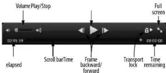
Figure 32-2: The Movie control bar.
Volume
The volume control allows you to set the playback volume for the movie's audio track.
Play/Stop
The Play/Stop button starts and stops movie playback.
Full screen
Click the full screen control to enter or exit full-screen mode. If you have multiple monitors, place the movie window on the monitor you wish to fill before entering full-screen mode. If the movie window is full screen when you save and close the file, it will reopen in full screen mode when the project is reopened. To exit, press the escape key as a shortcut.
Time elapsed/remaining
Displays the amount of time already played (elapsed) and yet to be played (remaining).
Scroll bar
The scroll bar shows where in the movie you are, and can be used to "scrub" the movie or to set your location in the movie. If Audible mode is turned on (with the speaker button in the Control Panel), MIDI data will scrub along with the movie.
Frame backward/forward
The frame backward/forward buttons move through the movie one frame at a time. Note that this means movie frames, not SMPTE frames. A movie may have 15 fps, 30 fps, or even a number which varies throughout the movie. The left/right arrow keys will also work if the window is active.
Window resizing
Drag the bottom right corner to resize the movie window, while maintaining its original aspect ratio. Shift-drag to resize and change aspect ratio of the window, which will add black bars (pillar box or letter box) above or below the movie as needed. Drag again without the shift key to remove the black bars.
Popping in and out of the Consolidated Window
Double-click anywhere on the movie to pop it in or out of a cell in the Consolidated Window. For example, you may want to edit with the movie displayed in a window cell, then pop it out and go full-screen to review your edits. Exit full-screen mode and double-click it again to pop it back into the original window cell.
THE MOVIE TRACK
Use the Sequence Editor track selector (see “The Track Selector” on page 377) to display the Movie track, which displays the movie you’ve opened in the Digital Performer project, if any. For details about the movie track, see “The movie track” on page 408. All of the controls for the Movie window, such as the movie start time, audio output settings, and mini-menu, are available in the track setting panel to the left of the movie track, as shown in Figure 32-3.

Figure 32-3: The movie track and movie window mini-menu
MOVIE WINDOW MINI-MENU COMMANDS
The Movie window mini-menu can be accessed by right-clicking anywhere on the movie or by going to the Movie track settings panel in the Sequence Editor (Figure 32-3).
Size: (Movie track mini-menu only) Lets you choose how big or small the movie track is displayed in the Sequence Editor.
Set Movie: Presents you with a standard file dialog to choose the movie file you wish to open.
Use Same Movie for All Sequences: Forces all sequences in the project to use one movie.
Clear Movie: Closes the movie.
Open Movie window: (Movie track mini-menu only) Opens the movie in a separate window.
Reveal Movie in Finder / Show Movie in Explorer: Switches out of Digital Performer and onto your computer desktop to show you the location of the movie on your computer hard drive.
Set Movie Start Time: Allows you to set the SMPTE time which corresponds to the beginning of the movie. If you want the movie to start at the beginning of the sequence, this should be set to the same time as the SMPTE chunk start time. You may need to try adjusting the start time by ±40 time code bits if you find that the frames in the movie don't precisely line up with the frame numbers in Digital Performer's counter.
Import Movie Audio: If the movie has an audio track, this command creates a new track in the current sequence and places the movie's audio into the new track. If the movie has no audio track, this command is grayed out.
Lock to Transport: (Movie window mini-menu only) If this mini-menu item is checked, the movie is locked to Digital Performer's transport. The movie will slave to Digital Performer as you play, stop, and locate. Conversely, you can use the movie controls to control Digital Performer. If the Lock to Transport is unchecked, you can control the movie and Digital Performer's sequences independently. This is useful if you want to preview a movie without synths blaring, wipers scrolling, and so on.
Chase Graphical Edits: (Movie window mini-menu only) When enabled, any graphical edits such as moving, trimming or stretching a soundbite or editing the placement of automation points will be chased by the movie window. This allows you to make edits quickly and see instantly how they relate to picture.
Chase Numeric Edits: (Movie window mini-menu only) When enabled, any numeric edits are chased by the movie window instantly.
Half Size, Normal Size, and Double Size: (Movie window mini-menu only) Resize the window. One of these may be checked if the window is already that size.
Movie Floats On Top: (Movie window mini-menu only) This causes the Movie window to "float" on top of other windows. This makes it possible to always have the Movie window visible because it will always be on top of other windows, even the active edit window.
Audio Output: (Appears in the Movie window mini-menu, right-click menu, and the Sequence Editor info panel) Lets you route the movie's embedded audio track to an audio output, bus, or aux track. From there, you can fully route, mix, and process it as desired within Digital Performer's mixing environment.
No External Video Output: Choose this menu item to disable video output to an external video device, such as a FireWire camera or a MOTU video interface.
HDX-SDI/HD Express/V4HD: If you have a MOTU video interface connected to your computer, choose it by name from the menu to output video to one or more video monitors connected to the interface.
FireWire: Lets you play back a DV-formatted QuickTime movie via a FireWire-based video hardware device such as a camera.
Video Output Playback Offset: Lets you compensate for the inherent playback delay in some video hardware devices.
SCRUBBING THE MOVIE WINDOW
You can “scrub” playback with the Movie window scroll bar. For more information, see “Scrubbing multiple MIDI tracks” on page 229.
IMPROVING MOVIE WINDOW PERFORMANCE
The following things may hinder the computer's ability to play a movie back smoothly:
■ Larger movies (in pixels)
■ Movies with higher frame rates
■ Playing the movie from slower drives
■ Resizing the window to non-optimal sizes (not double, full, or half size)
■ Having many other open windows with scrolling wipers, auto scroll, level meters, etc.
Avoiding these things will help your movies play back more smoothly.
EXTERNAL VIDEO HARDWARE OUTPUT
The Movie window can output SD or HD video to a video interface to view it as standard definition (SD) or high definition (HD) video on one or more external video monitors. MOTU video hardware and some third-party video hardware is supported.
MOTU video interfaces
Supported MOTU video devices include:
■ V4HD
■ HDX-SDI
■ HD Express
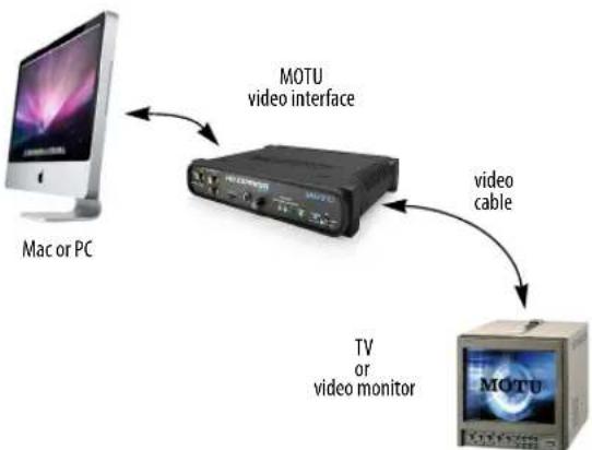
flowchart
graph TD
A["Mac or PC"] --> B["MOTU video interface"]
B --> C["TV or video monitor"]
C --> D["video cable"]
Figure 32-4: Connections for external video hardware output.
Each interface provides legacy SD output in all standard NTSC and PAL formats, including composite, component, S-video, and SD-SDI. They also provide high definition (HD) 720 and 1080 output in component, HDMI and HD-SDI, except the HD Express, which does not supply HD-SDI.
All interfaces provide at least sixteen channels of simultaneous audio output. MOTU video interfaces serve as capable video and audio I/O hardware solutions for film scoring and post production workflows.
Third-party video hardware
Under macOS 10.7 or later, video interfaces from AJA Video Systems and Blackmagic Designs are also supported.
Enabling external video hardware output
Install your video interface as instructed in the user guide. Be sure to check www.motu.com or the third-party manufacturer's web site for the latest up-to-date video driver installer. Run the MOTU Video Setup software (or third-party video setup utility) to ensure that the software can successfully communicate with the hardware. Consult the video interface's user guide for any trouble-shooting tips, if necessary.
Once you're video interface is running successfully, open a movie in Digital Performer. Then, display the movie track in the Sequence Editor (see "The Track Selector" on page 377). In the movie track mini-menu (Figure 32-3 on page 314), you should now see your MOTU video interface listed by name.
Choosing a video format
Choose the desired output format from the MOTU video interface sub-menu as shown in Figure 32-3 on page 314.
The only requirement for choosing a format is that the frame rate of the movie must match the frame rate of the chosen output format. If you get an error message regarding frame rate, make sure the video hardware is set to the same frame rate as the format you are choosing.
If you choose Auto-Detect Video Mode, Digital Performer automatically chooses the video format that best matches the frame rate and format of the current movie.
Once a format is chosen, Digital Performer conforms the movie to the chosen output format, adding letter box or pillar box formatting as required to best reconcile the movie's aspect ratio with the chosen output format.
Turning off external video output
To disable external video output, choose No External Video Output from the mini-menu.
External video playback offset
Some video monitors introduce a small delay during playback, from the time they receive a video frame to the time it actually appears on screen. The specific amount of delay depends on the monitor, with most devices in the range of a few frames. Digital Performer can automatically compensate for this offset, so that external video playback remains frame-accurate with audio, both
when the transport is stopped and during playback. This offset feature supports video hardware output and FireWire video output.
To set the external video playback offset, choose Video Output Playback Offset> Other from the Movie window mini-menu (Figure 32-5):

Figure 32-5: Setting the external video device playback offset.
Choosing an offset
Specify the number of frames and timecode bits (there are 80 timecode bits per frame). You can experiment with different values to determine the correct offset. Enter a frame amount (and timecode bit value, if needed), and then try playing back your video. Sharp audio hits or time code burn in are quite useful for judging the offset amount.
Creating offset presets
The Set Playback Offset dialog (Figure 32-5 above) lets you create named presets for different devices. This lets you conveniently save and recall multiple offsets by name, in situations where you are using multiple devices for playback. Use the Add, Delete, Change and Rename buttons to manage your playback offset presets.
The Movie window has the ability to output standard definition (SD) video to a FireWire video output device. You can then use a FireWire-equipped camcorder or FireWire video converter to view it as standard definition (SD) video (either NTSC or PAL) on a television or video monitor as shown below in Figure 32-6:

flowchart
graph TD
A["FireWire equipped Mac or PC"] -->|FireWire cable| B["DV camera or FireWire-to-video converter"]
B -->|video cable| C["TV or video monitor"]
C --> B
Figure 32-6: Connections for FireWire video output.
FireWire video output is limited to standard definition only. If you need HD video output, use a MOTU video interface as described earlier.
FireWire video converters
There are numerous choices for FireWire video devices that can convert FireWire video to NTSC or PAL for viewing on a standard TV screen or video monitor. Most camcorders provide either legacy SD video output (component, composite or S-video) and/or digital output in the form of HDMI (or in some cases, SDI-SDI). Dedicated FireWire video converters are also available.
Enabling FireWire video output
Connect a FireWire DV camera or converter as shown in Figure 32-6. Turn it on, and, if it's a camera, put it in playback mode. Open a movie in Digital Performer. Then, display the movie track in the Sequence Editor (see "The Track Selector" on page 377).
Choosing a video format
Choose the desired output format from the FireWire sub-menu. The only requirement for choosing a format is that the frame rate of the movie must match the frame rate of the chosen output format. If you get an error when choosing the format, make sure the video hardware frame rate (NTSC or PAL) matches the output format you are choosing.
If you choose Auto-Detect Video Mode, Digital Performer automatically chooses the video format that best matches the frame rate and format of the current movie.
Turning off external video output
To disable external video output, choose No External Video Output from the mini-menu.
FireWire video output does not support audio
FireWire video output from Digital Performer only supports video; it does not transfer audio. Therefore, this feature cannot be used to transfer a complete movie (sound and picture) to a video camera.
FireWire video playback offset
FireWire video devices introduce a small amount of delay during playback. The specific amount of delay depends on the device, with most devices in the range of 4-5 frames. Digital Performer can automatically compensate for this offset, so that video playback remains frame-accurate both when the transport is stopped and during playback.
To set the FireWire video playback offset, see "External video playback offset" on page 316.
STREAMERS AND OTHER VISUAL CUES
Digital Performer can superimpose streamers, flutters and punches on the Movie window, no matter how the video is being displayed (on the computer screen, through a FireWire output
device, or through a MOTU video interface). For information about how to set up and program visual cues, see chapter 66, “Streamers, Punches and Flutters” (page 787).
EXPORTING A MOVIE
You can bounce an audio output bundle (mono, stereo or any surround format), together with video, to a movie file. This allows you to export a complete movie from Digital Performer in one easy operation, complete with a sound track that you've created in Digital Performer, as well as any visual cues (streamers, punches and flutters) that you would like to overlay on the resulting movie. For details, see “Bouncing to a Movie” on page 966.
CHAPTER 33 ReWire
OVERVIEW
What is ReWire? ....319
Setting up ReWire 319
MIDI output ....320
Multiple ReWire audio outputs ....321
Synchronization and transport control....321
Tempo control....321
Plug-in processing on ReWire synth inputs.....321
Renaming ReWire synth inputs....321
Quitting the ReWire synth ....321
WHAT IS REWIRE?
Re Wire
ReWire ™ is a software component for macOS and
Windows developed by Propellerhead software that allows you to route computer-generated audio from a ReWire synth such as Reason™ or Live™ directly into an audio track in Digital Performer's virtual mixing environment, right alongside the MIDI and hard disk audio tracks in your project. The ReWire synth acts as a “virtual instrument” that streams its audio output into Digital Performer, allowing you to apply real-time effects processing and automated mixing within the Mixing Board window, with very accurate timing throughout the whole process. ReWire also supports basic transport control, allowing you to play, stop, rewind, shuttle, set loop points, and so on, in either Digital Performer or the ReWire synth.
ReWire synths are different than plug-ins because they run as a separate application. But they can still operate in a tightly integrated way with Digital Performer, so practically speaking, there is little difference.
ReWire is easy to set up and use. Refer to the following brief sections for a few important pointers about using ReWire.
SETTING UP REWIRE
To set up ReWire:
1 Install the ReWire synth.
ReWire is automatically installed in your System Folder when you install Reason.
2 Test the ReWire synth.
After installing the ReWire synth, it is a good idea to open it independently of Digital Performer to test and make sure that the installation was successful. To do so, quit Digital Performer so that it is not running, and then open the ReWire synth by itself.
3 Play a few demo songs in the ReWire synth to confirm that it is functioning properly on its own.
4 Quit the ReWire synth.
5 Launch Digital Performer. ReWire requires that you open Digital Performer first, before launching a ReWire synth.
At this point, you should see the ReWire synth inputs in Digital Performer's audio input menus, as demonstrated in Figure 33-1. These inputs are supplied by ReWire, even when the ReWire synth is not currently open as an application.
6 Before you launch the ReWire synth, do one of the following:
■ Create a stereo Aux track, give it a valid (currently active and therefore not italicized) audio output assignment, and then assign the ReWire synth main Mix (L/R) as its audio input OR
■ Do the same thing using regular stereo audio track AND record-enable or input monitor-enable the track.
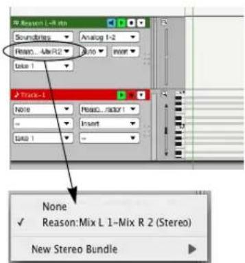
Figure 33-1: ReWire provides the ReWire synth inputs in Digital Performer, even when the ReWire synth is not running. Assign at least one the ReWire synth input to a Digital Performer audio track or aux track before launching the ReWire synth. In this example, the ReWire synth main L/R mix is being assigned to a Digital Performer Aux track. Also make sure that the aux track has a valid audio output assignment.
Either one of these two procedures activates Digital Performer as a ReWire destination for the ReWire synth. If you don't do so, the ReWire synth will not "see" Digital Performer as an audio output destination, and you'll see an alert window when you launch the ReWire synth. If this happens, you need to quit the application, assign an input in Digital Performer as described above, and then relaunch.
The audio output assignment for the ReWire track in Digital Performer can be any destination you want: a pair of audio outputs on your MOTU audio interface, the speaker output on your computer, a Digital Performer virtual bus, etc. The only requirement here is that it must have a currently valid output assignment (one that is displayed in normal text, rather than italicized text).
7 After assigning a the ReWire input to at least one audio track in Digital Performer as described in the previous step, launch the ReWire synth. That's it. When the ReWire synth plays, you'll now see its audio output present on the Mixing Board channel strip for the track it's assigned to. In addition, you'll hear its output on the ReWire synth track's playback destination.
MIDI OUTPUT
After audio is flowing as described in the previous section, any ReWire instruments (such as a synth module in Reason) should appear as MIDI output destinations in the MIDI output assignment menus for Digital Performer's MIDI tracks. This allows you to use your ReWire instrument like a sound module, where you sequence MIDI in a Digital Performer MIDI track, and trigger the ReWire instrument.

Figure 33-2: In this example, Reason instruments appear as MIDI destinations in the output menu for a MIDI track.
Publishing ReWire device MIDI inputs/outputs to other Core MIDI software (macOS only)
Digital Performer publishes ReWire MIDI inputs and outputs to all Core MIDI-compatible software. This means that while Digital Performer and a ReWire application are running together, you can send MIDI data to the ReWire application from any Core MIDI-compatible software.
Similarly, you can send MIDI data to any Core MIDI application from the ReWire instrument as well.
MULTIPLE REWIRE AUDIO OUTPUTS
Some ReWire-compatible applications provide multiple audio outputs. After the ReWire application has been launched, you can access its audio outputs in the Instruments tab in the Bundles window. These outputs function in the same way as multiple outputs. For details, see “Multiple audio outputs” on page 158.
SYNCHRONIZATION AND TRANSPORT CONTROL
ReWire provides inter-application synchronization and transport control between applications. This means that you can play, stop, rewind, locate and otherwise manipulate the transport controls in either program and both the ReWire synth and Digital Performer will remain in perfect synchronization with each other.
TEMPO CONTROL
Here are a few things you should keep in mind about controlling tempo. You can change the playback tempo of both the ReWire synth and Digital Performer from either program, as long as you have Digital Performer's tempo slider set to tempo slider mode.
When Digital Performer is operating under tempo slider mode, when you first open a ReWire synth file that has a different tempo setting, Digital Performer's tempo slider will jump to the tempo of that ReWire synth file. If desired, you can then re-adjust the tempo in either program.
If you have Digital Performer's tempo slider set to Conductor Track mode, Digital Performer's Conductor track governs the tempo and the tempo cannot be changed in the ReWire synth.
PLUG-IN PROCESSING ON REWIRE SYNTH INPUTS
You can apply Digital Performer real-time effects processing, as well as third party plug-ins, to your ReWire synth audio by simply adding plug-ins as usual to the ReWire tracks in Digital Performer's Mixing Board.
RENAMING REWIRE SYNTH INPUTS
If the ReWire synth input names in Digital Performer's audio input menu (as shown in Figure 33-1) are not to your liking, you can rename them as desired with the Bundles window in the Studio menu.
QUITTING THE REWIRE SYNTH
ReWire does not allow Digital Performer to quit while the ReWire synth is open. If you try to do so, you'll see an alert window that informs you that you must first quit the ReWire synth.
Part 5
Editing
CHAPTER 34 Editing Basics
OVERVIEW
Digital Performer provides unmatched features for editing MIDI data, audio data and both at the same time. This chapter provides a introduction to editing in Digital Performer and covers several general features than can be employed universally while editing.
Unlimited Undo/Redo....325
Editing during playback....325
Selecting and searching ....325
Region editing....325
Track groups....326
View menu....326
View Filter....328
Zooming ....331
Scroll To ....334
Graphic editing techniques....334
Audio editing basics....335
Sample accurate editing ....337
Audible mode....337
UNLIMITED UNDO/REDO
Digital Performer supports unlimited Undo/Redo. It can remember everything you have ever done to a project, even after you close and quit, across any number of sessions, all the way back to the moment the project was first created. There are several commands in the Edit menu to support a simple, single-step undo behavior, plus several commands to step forward and backward through the undo history. The Undo History window provides a complete log of actions and numerous features for navigating through the undo history and jumping to any point. or complete details, see “Undo History” on page 574.
EDITING DURING PLAYBACK
Almost all edit operations in Digital Performer can be done during playing back so that you don't have to stop and start to hear the result. For example, you could Transpose while the sequence is playing and then use the Undo/Redo command as the music continues playing to compare the original and modified data.
SELECTING AND SEARCHING
To edit anything in Digital Performer, you must first select it. Digital Performer provides many useful ways to make selections, from a single event—or event parameter—to the entire project. After you’ve made a selection, you can apply Digital Performer’s many powerful Edit menu commands to whatever is selected. Be sure to learn all of the ways to make selections by reading chapter 45, “Selecting” (page 547) and chapter 46, “Searching” (page 561). Both chapters contain many shortcuts that will speed up your work.
REGION EDITING
A region is a span of time across one or more tracks. Digital Performer's edit windows provide flexible region editing across one or more tracks, allowing you to edit data within that region with a wide range of edit operations. You can edit audio tracks, MIDI tracks, and both simultaneously. The process of region editing consists of the following basic steps:
1 Select a region.
2 Apply the desired operation from the Edit or Region menus.
These steps are discussed briefly in the following sections.
Selecting regions
There are many ways to select regions. For a summary, see “Selecting a time range” on page 551.
Applying Edit and Region menu operations
After you've selected a region, you can choose any command from the Edit or Region menu. Edit menu commands affect audio in the same way as MIDI. See chapter 47, "Edit Menu" (page 573) and chapter 48, "Region Menu" (page 593) for details about these basic commands. Region menu commands affect audio as discussed below.
Region menu exceptions for audio
The Change Duration command does not affect soundbites. To change a soundbite's duration, see "Graphic time stretching of audio" on page 396 and chapter 82, "Scale Time" (page 947).
The Transpose command has the ability to transpose the pitch of audio, with or without formant correction. For details, see “Transpose” on page 594 and chapter 81, “Transposing Audio” (page 935).
Some Region menu commands that affect timing (such as Retrograde) only affect the placement of soundbites—that is, the attack time of the soundbite. They do not have an effect on the audio data within the soundbite. For example, if you use Reverse Time over a region containing a soundbite, the soundbite audio data does not play backwards like a reversed sample. Instead, the placement of the soundbite within the region is modified, along with other soundbites and MIDI note data, according to their attack times within the region. To reverse the audio in the soundbite, you would use choose Audio menu> Plug-ins> Reverse. For details about Reverse Time, Retrograde, and other Region menu commands for MIDI, see chapter 48, "Region Menu" (page 593). For information about reversing audio, see “Reverse” on page 77 in the DP Plug-in Guide.
TRACK GROUPS
Digital Performer allows you to create an unlimited number of track groups, and tracks can be linked for mixing, editing, both, or for a customized set of operations that you specify. Tracks can be a member of more than one group. Groups can also be “nested” within each other. For further details, see “Track Groups” on page 188.
VIEW MENU
The View menu provides many useful shortcuts for controlling what you see in Digital Performer's windows and how information is displayed.
For details about the Filters command, see "View Filter" on page 328.
Show/Hide Tracks
The View menu provides several commands for showing and hiding tracks in any Digital Performer editor that can display multiple tracks, such as the Sequence Editor, Tracks List, Mixing Board or QuickScribe window.
When using these commands, it can be useful to open the Track Selector to get an overview of the results.
To zero in on just the tracks you want, it can be useful to start out with all tracks hidden: choose View menu > Hide Tracks > All.
Each Show/Hide Track command provides a sub-menu that allows you specify which tracks you wish to show or hide. For example, if you choose Show Tracks > Play Enabled, all currently play-enabled tracks will be shown.
Showing and hiding is a one-shot operation; in other words, these commands are not checkable (i.e. “sticky”). Instead, they produce a result for the
currently active (focused) window, at the moment you choose the command. You can then further adjust what is shown or hidden using additional consecutive show/hide command(s), or by using the track selector.
When using several show/hide commands consecutively, the effect is cumulative, which allows you to fine-tune the track display.
Show Tracks
The Show Tracks command “unhides” the type of track you choose from the sub-menu. The visibility of any other tracks remains unchanged. This command is good for adding tracks to the display.
Show Only Tracks
The Show Only Tracks command “unhides” the type of track you choose from the sub-menu and hides all other tracks. This command is good for “soloing” the type of track you choose from the sub-menu.
Hide Tracks
The Hide Tracks command hides the type of track you choose from the sub-menu. The visibility of any other tracks remains unchanged. This command is good for hiding tracks you don't want to see, while leaving other track types visible.
Track Layouts
A track layout is a “snapshot” of which tracks are currently shown and hidden at the time it is created. The commands in the Track Layouts sub-menu let you create, name, rename and delete track layouts. To create one, show and hide tracks as desired and then choose View menu > Track Layouts > Save Track Layout As. The resulting track layout appears by name at the bottom of the Track Layouts sub-menu, where you can choose it to recall the layout. Saved track layouts also appear in the Commands window (Setup menu), where you can assign them to keyboard shortcuts. To view them, type Track Layout into the Commands window search field. Applying a track layout preset hides tracks that did not exist at the time the preset was created.
Show Only
The Show Only... commands in the View menu control the display of automation data and MIDI continuous controller data in the Sequence Editor and Graphic Editor.
When Show Only the Active Edit Type is checked, the Edit Layer menu (in the Sequence Editor track settings pane as shown in Figure 38-10 on page 380) and the Graphic Editor insert menu (as shown in Figure 39-1 on page 412) control the type of automation data that will be visible.
To use the Show Only Selected Types (Quick Filter) command (to make it not grayed out), the following two conditions must be met:
■ the Show Only Active Edit Type command is unchecked, and
■ at least one MIDI controller event must be selected
If these two conditions are met, then choosing this command will “solo” the selected data type, temporarily hiding all others. This command is the same as the Show only check box (explained on Figure 39-1 on page 412).
Show/Hide Lanes
The view menu provides several commands for showing and hiding automation lanes in the Sequence Editor (“Displaying automation lanes” on page 403). To activate these commands (make them not grayed out), make the Sequence Editor visible and active. Choose Show All Lanes with Data to expose any automation lanes that contain data of any kind. Choose Show/Hide Lanes to show all lanes or hide any currently visible lanes.
Grid
The commands in the Grid sub-menu show and hide various types of grid lines in the Sequence Editor and graphic editors (see “Edit Window guides” on page 91).
Colors
The Colors sub-menu in the View menu lets you control track colors in Digital Performer. See "Track colors" on page 84.
Auto Scroll
Auto Scroll controls how windows with time lines scroll during playback. See “Auto scroll” on page 226.
VIEW FILTER
The View Filter (View menu) allows you to specify what types of MIDI, audio and mix automation information are affected by Edit and Region menu operations. Using this feature, you can extract different types of information from a region without having to laboriously edit out events that you don't want. For example, if you wanted to copy only patch changes and aftertouch from a track, you could select only those items in the View Filter. Only the selected data would be copied to the clipboard. As another example, if you were editing Tempo changes in the Conductor track, you could set the View Filter for Tempo changes only. You could then cut and paste Tempo changes without erasing or in any way affecting meter and key changes in the same region. Remember, the View Filter setting you make will affect all the commands from the Edit menu, and all editing from the tracks window. You should therefore make sure to change it back after doing a specific editing task since it may cause unwanted effects the next time you use the Edit commands.
Global View Filter vs. Event List View Filter
The View Filter window actually represents two separate Filters: the Global View Filter and the Event List View Filter. After you have the window open, you can switch between them with the tabs at at the top of the window.
To set the View Filter:
1 Choose View Filter from the View menu.

Figure 34-1: The View Filter lets you control what you see and what will be affected by edit operations. Use the tabs at the top of the window to switch between the Global View Filter and the Event List View Filter.
2 Choose the types of data to be edited as follows:
To do this Do this
| To view all types of data Click Set All. | |
| To hide all types of data Click Clear. | |
| To view one data type and hide all others | Option/Alt-click its check box. |
| To hide one data type and view all others | Command/Ctrl-click its check box. |
| To show/hide controllers or mix automation | Use the controllers menu as described in “Specifying controller numbers and automation types in the View Filter” on page 329. |
3 If you want to make separate view filter settings for Event Lists, choose the Event List View Filter tab at the top of the window and repeat this procedure as desired for the Event List settings.
Always be aware of the View Filter settings
When using the View Filter, keep these rules in mind: The View Filter settings you select will stay in effect until you change them, and they affect all editing operations. When you are done using the View Filter, you should reset it.
Specifying controller numbers and automation types in the View Filter
The buttons under the Automation and Controllers check box in the View Filter allow you to quickly choose which automation and controller data to include in Edit operations:
■ All: All automation data and controllers will be affected by Edit operations.
- All except: All automation data and controllers except the types you enter will be affected by Edit operations.
■ Only: Only the automation data and controller types you enter will be affected by Edit operations.
To specify controller numbers and mix automation data types for the All Except and Only options, choose them from the Add menu. To remove a data type from the list, click it and click Remove.
The View Filter window mini-menu
The View Filter window mini-menu has commands in it that let you name, save, recall and edit your favorite View Filter settings.
Saving View Filter settings
To save a View Filter setting, make the settings you want and then choose Save Settings from the mini-menu. A window appears to let you name it. Type in a name and click OK. Saved settings are independent of Global Filter and the Event List filter. In other words, it doesn't matter which filter is active in the window when you save filter settings.

Figure 34-2: Saving a view filter setting.
Recalling saved settings
To recall a saved setting, choose it by name from the lower portion of the View Filter mini-menu. When you recall saved filter settings, they are restored as you saved them for whichever filter is currently displayed.

Figure 34-3: Recalling a saved View Filter setting.
Renaming, deleting, & re-ordering settings To rename, delete or change the order in which the filter settings are listed in the mini-menu, choose Edit Settings from the View Filter mini-menu. Click the setting you wish to rename or delete. Drag the handle to its left to move it up or down in the list. The order they appear in this list is the order they appear in the mini-menu.
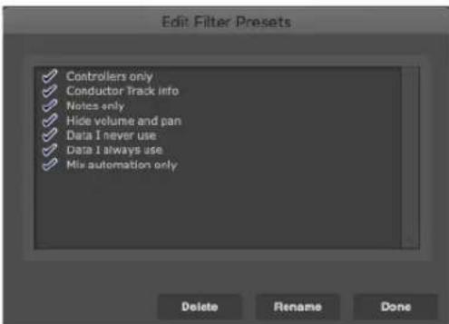
Figure 34-4: Renaming, deleting and re-ordering filter settings.
The Event List View Filter
The Event List View Filter allows you to specify what types of MIDI information are displayed in Event List windows. You can open the Event List View Filter from the View menu by holding down the Option/Alt key while accessing the menu. The Event List View Filter is actually the same window as the Global View Filter. The only difference is that the tabs at the top of the window switch between Global View Filter settings and Event List View Filter settings.
The Global View Filter affects all windows that display MIDI data and Conductor Track data, including the Event List; the Event List settings only affect the Event List. That is, when something is hidden in the Global View Filter, it will also be hidden in the Event List. However, you may hide additional items just in the Event List by disabling them in the Event List View Filter.
Both View Filter settings determine which types of events are affected by Edit menu commands when the data is selected in the Event List. Here's a simple rule to remember: if you can see an event in the Event List, it will be affected by edit commands.
View filter example: removing a specific type of data from a track
This works for removing one or more particular kinds of data from a track, such as mono key pressure, patch changes, etc.
1 Choose View Filter from the View menu.
2 Check only the check box for the type of data you wish to remove.
Option/Alt-click on the check box for the type of data to be removed; all other check boxes will uncheck.
3 In the Tracks window, select the track with the data to be removed.
Click on the track name; it will highlight.
4 Enter the Start and End times of the region in the Selection bar.
5 Choose Erase from the Edit menu.
If you want to save this information for possible future use, cut it instead of erasing it, and paste the information into a new and separate storage track. You can later merge it back into the original track if you like.
Here's an alternative method for removing a specific kind of data using the Event List:
1 Open the Event List for the track.
2 Choose View Filter from the View menu.
3 Choose Event List View Filter tab at the top of the window.
4 Check only the check box for the type of data you wish to remove.
This will display only that type of data in the Event List. Option/Alt-click on the check box for the type of data to be removed; all other check boxes will uncheck.
5 Select a region of events.
Click on the first event and drag over the rest of them.
6 Choose Erase from the Edit menu.
ZOOMING
Zooming in the edit windows is similar to the zooming found in most computer graphics programs. When zooming in, objects become larger as the display magnifies a portion of the screen. When zooming out, objects shrink as the display encompasses a larger region.
There are many ways to zoom the edit windows, as explained in the following sections. Individual windows may also have additional zoom abilities; refer to the chapters on each window for more details.
Zoom buttons
The Time zoom buttons appear in the bottom right corner of the window. Zooming out ( - ) gives you an overview by compressing more time into the window; zooming in ( + ) focuses on a shorter period of time at a higher viewing resolution.
Some windows, such as the Sequence Editor, also have vertical zoom buttons to increase the height of the data you're viewing.

Zooming quickly by pressing
If you press continuously on a zoom button, the display will zoom continuously until you release the mouse.
Wiper zooming
In many windows that display the playback wiper, you can very quickly and conveniently zoom in and out by Control/Win-dragging vertically on the green playback wiper handle. For details, see "Zooming with the wiper" on page 228.
Zooming with the scroll wheel
If your mouse has a scroll wheel, you can use it to zoom. Simply position the cursor over the zoomable portion of an editor and hold down the Option/Alt key while spinning the scroll wheel. To zoom vertically, hold Option+Control or Alt+Win.
Zooming with a track pad
If you have a track pad, you can use standard pinch gestures to zoom the time ruler in and out. If you hover the cursor over the MIDI note grid pitch ruler, track pad pinching zooms the pitch ruler.
Keyboard zooming shortcuts
Below are several keyboard shortcuts for zooming. In addition, all of the zooming shortcuts discussed in the next section (“Zoom menu shortcuts”) have keyboard shortcuts, which are available in the Commands window (see chapter 9, “Commands” (page 105).
Shortcut What it does
| Command/Ctrl-left arrow Zoom out horizontally. | |
| Command/Ctrl-right arrowZoom in horizontally. | |
| Command/Ctrl-up arrow Zoom in vertically (track height or note grid). | |
| Command/Ctrl-down arrow | Zoom out vertically (track height or the note grid). |
Option/Alt key When added to the above shortcuts, the Option/Alt key zooms all the way.
Zoom menu shortcuts
The View menu > Zoom sub-menu (Figure 34-5 on page 332) provides many useful options for magnifying or reducing the data displayed in graphic editors. Digital Performer offers completely unlimited zooming between the minimum and maximum horizontal zoom levels.
| Zoom In Horizontally | ⌘→ |
| Zoom Out Horizontally | ⌘← |
| Zoom In Vertically | ⌘↑ |
| Zoom Out Vertically | ⌘↓ |
| Zoom To Default Zoom | ⌘N |
| Zoom To Selected Time Range | ⌘S |
| Zoom To Selection | |
| Zoom To Track | |
| Zoom Back | ⌘[ |
| Zoom Forward | ⌘] |
| Auto Zoom Track | |
| Zoom to Setting 1 | ⌘1 |
| Zoom to Setting 2 | ⌘2 |
| Zoom to Setting 3 | ⌘3 |
| Set Zoom Setting 1 | ⬆⌘1 |
| Set Zoom Setting 2 | ⬆⌘2 |
| Set Zoom Setting 3 | ⬆⌘3 |
Figure 34-5: The Zoom menu in Sequence Editor mini-menus.
Zoom in/out
Zooming in (either vertically or horizontally) enlarges the data; zooming out reduces it.
Zoom To Default Zoom
Zoom To Default Zoom restores the original zoom level for the window.
Zoom to Selected Time Range
Zoom to Selected Time Range fits the current selection horizontally to the left and right edges of the window.
Zoom to Selection
Zoom to Selection fits the current selection both horizontally and vertically in the window. This command can be used in the Sequence Editor, MIDI Editor and Track Overview.
Zoom to Track
Zoom To Track fits the currently selected track in the Sequence Editor to the full height of the window.
Zoom Back and Zoom Forward
As discussed in "Zoom history and Zoom
Forward/Backward" on page 333, the Zoom Back and Zoom Forward commands keep track of every zoom operation that you do since you first opened the graphic editor. Therefore, they allow you to step backwards and forwards through all of the different scrolling and zooming actions you've taken. Just keep choosing them over and over to work your way backwards or forwards.
Auto Zoom Track
When you select a MIDI track in the Sequence Editor and choose Auto Zoom Track, the vertical zoom level and vertical scroll of the track is automatically set, such that all MIDI note data in the track will be visible within the track's lane in the Sequence Editor. The track will continue to automatically zoom, even when edits are applied to the MIDI note data in the track, so that all notes always remain in view.
If, at any time, you manually zoom the track, perform pencil tool editing, or drag and drop material into the track, auto-zooming becomes disabled so that it doesn't interfere with your edits.
When you are finished, you can re-enable it again by selecting the track and choosing the Auto Zoom Track command again.
Working with the zoom settings
The zoom settings let you store favorite zoom settings and easily restore them by choosing them from the menu (or pressing their key binding). To store a zoom setting:
1 Zoom the display the way you want.
2 Choose the desired Set Zoom Setting command in the menu.
To restore the zoom setting, choose the desired Zoom to Setting command.
Switching among 2 or 3 zoom settings
The zoom settings commands discussed above are ideal for zooming among several different zoom settings. For example, you might want to switch back and forth between the sample level and an overview level to consecutively make small sample edits and then audition them.
Zoom tool
The Zoom tool (magnifying glass) in the Tool palette lets you zoom in on a portion of the edit window by dragging a zoom box over it. In the time ruler or continuous data grid, drag horizontally to zoom the time axis only.

Figure 34-6: Zooming with the Zoom tool.
See "Zoom tool shortcuts" on page 352 for many Zoom tool shortcuts.
Zoom history and Zoom Forward/Backward
Digital Performer remembers consecutive zoom operations in a window. For example, if you zoom in three times consecutively to get a closer look at some data, Digital Performer remembers each zoom setting. You can then use Zoom Backward and Zoom Forward shortcuts to move forwards and backwards through these remembered zoom settings.
Zooming, Edit Resolution and nudging
Editing is allowed at any zoom setting. However, the current zoom level may affect the resolution at which events can be edited by dragging. For example, let's say that the Edit Resolution unit is set to 20 ticks. If you zoom way out, you will not be able to drag a note by only 20 ticks because one screen pixel, which is the smallest unit of movement on the computer screen, will equal a time value greater than 20 ticks. So, even if you move the note as little as possible, you will still have moved it more than 20 ticks.
In the example above, Digital Performer handles the situation by constraining location to multiples of 20 ticks. When you move the note, its new location will become the nearest multiple of 20 ticks, such as 80, 140, or 420 ticks.
If you need more precision, zoom in. Or, you can nudge data in precise increments at any zoom level use the arrow keys and the Nudge Amount window. See “Nudge” on page 358.
SCROLL TO
The Scroll sub-menu (View menu) provides two commands for scrolling immediately to the start or end of the current selection or file. The Scroll to File Start or End command applies to the sequence time line for edit windows. In the Waveform Editor, it applies to the audio file being viewed.
GRAPHIC EDITING TECHNIQUES
Digital Performer has many powerful editing features. Most editing can be done with the mouse using familiar actions like clicking, dragging, and Shift-dragging. Such actions can shift data, change note pitch and duration, reshape continuous data curves, and more.
The sections below describe basic features that you will find helpful when working in Digital Performer's graphic environment.
Shift-drag to constrain
If you hold down the Shift key before you begin to drag a selection, the pointer's movement on the screen will be constrained to either the horizontal or vertical axis, depending on the initial direction of movement. For example, if you click the mouse, hold down the Shift key, and drag upwards, the mouse will only move up or down: it will not stray left or right.
Constraining mouse movement in this way is often extremely helpful. For example, if you want to modify just the pitch of a note without changing its location, the Shift key allows you to do so by preventing the mouse from moving left or right.
Option/Alt-drag to duplicate
Option/Alt-dragging an event (or several selected events) leaves the original data unchanged and places a copy of the data at the destination.
Option/Alt-dragging is a convenient shortcut for copying and pasting.
Canceling while dragging
If you are in the middle of dragging, and you change your mind, you can press the escape key while dragging to immediately cancel the operation and restore the data to its original position, unchanged.
Shift-clicking to select non-adjacent events
Holding down the Shift key also serves as a useful way to select more than one event. For example, if you have already selected a note and you want to select another, scroll to the other note (if necessary) and Shift-click on it (but don't drag). It will highlight, and the first note will remain highlighted.
Other selection techniques
There are many other useful selection techniques. See chapter 45, “Selecting” (page 547).
Dragging multiple data types
The Shift-click method of selection allows you to simultaneously select and drag multiple data types.
For example, to move a loop containing notes, pitch bend data, and a patch change, select all four data types by Shift-clicking and drag them to a new location.
Nudging
The Nudge Amount (Snap Information window) lets you move selected data with the left and right arrow keys by any amount in any unit of measurement that you choose. See “Nudge” on page 358.
Using Edit Resolution
When the Snap to Grid check box is selected in the Snap Information window, data that is moved or inserted will 'snap' to positions corresponding to the current edit resolution setting. For example, if the current grid resolution unit is 240 ticks, events that are moved with the mouse will snap to positions at every 240 ticks on the grid. If the Snap to Grid check box is not checked, events will move freely. You can temporarily override the current grid setting by holding down the Command/Ctrl key as you drag. Snapping can occur either relative to the original position of the data event, or relative to an absolute grid based on the timeline's bars and beats. For further review, see "Snap Information" on page 355.
Using Undo
The Undo command in the Edit menu will undo the last action you executed. For example, if you move a note and then change your mind, you can choose Undo Move from the Edit menu and the note will return to its original position.
AUDIO EDITING BASICS
The following sections explain several important concepts to keep in mind when editing digital audio.
Soundbites in a track are ‘clones’ of the original. It is important to understand that soundbites in a track are “clones” of the original soundbite in the Soundbites window as shown below in
Figure 34-7. They do not actually consist of the soundbite itself; they are a reference to the original soundbite. As a result, you can freely cut, copy, paste, duplicate, and re-arrange a soundbite in a track as much as you want without affecting or duplicating its original in the Soundbites window. On the other hand, if you change the soundbite's name or length, all instances will change, including the original.

Figure 34-7: Soundbites in tracks are merely references, or "clones", of the original soundbite in the Soundbites list. In turn, the Soundbites there are references to the original audio data in the audio file on the hard disk.
Interestingly, the original soundbite is itself merely a reference to something else: it is a pointer to the original audio data in the audio file, as shown above in Figure 34-7. As a result, the amount of data that you generate by duplicating soundbites is insignificant, since soundbite data is merely a pointer to the actual audio data.
Non-destructive, destructive and constructive audio editing
When you edit audio, your edit operation is either non-destructive, destructive or constructive. A clear understanding of these terms will help you make better decisions about how to edit your audio. Here is a brief explanation:
Type of audio editing Explanation
| Non-destructive Original audio data is preserved. Only pointers to the original audio data are modified.Example: trimming the edge of a soundbite in the Sequence Editor. |
| Destructive Original waveform data is permanently modified. Example: normalizing audio in the Waveform Editor. |
| Constructive Original audio data is preserved on disk while being replaced in the Digital Performer project by new audio generated by the constructive editing operation. Example: applying an audio effect via the Audio menu. |
For further explanation, see “Non-destructive editing” on page 57 in the DP4 Getting Started Guide, “Destructive’ editing” on page 528 and “Constructive editing” on page 922.
Non-destructive Edit menu and Region menu editing
Edit menu and Region menu operations are non-destructive when applied to audio that has been selected in the Sequence Editor, Event List, or Tracks window, except for the Transpose command in some cases. When using Transpose with the “Transpose audio by creating new soundbites”, audio data is processed constructively, (where the original audio is replaced by newly processed audio.) See “Constructive editing” on page 922.
Destructive editing in the Waveform Editor
Edit menu operations are destructive when applied to audio that has been selected in the Waveform Editor. In addition, only some Edit menu commands can be applied to audio in the Waveform Editor. For details, see “Edit menu operations” on page 542. (In the Region menu only the Transpose command can be applied in the Waveform Editor.) The Waveform Editor also provides other destructive waveform editing operations, such as Pencil tool editing of digital audio samples and DSP features such normalize, reverse, time dilation, etc. For details, see chapter 44, “Waveform Editor” (page 525).
You can't mix audio and MIDI in the same track
In Digital Performer, you cannot mix the two data types together into one track. You can, however, edit both types of tracks simultaneously as described in the next section.
Editing audio and MIDI data simultaneously
As an integrated audio and MIDI editing environment, Digital Performer lets you to select audio tracks at the same time as MIDI tracks for simultaneous editing of audio and MIDI data. For example, you can select all tracks of an eight measure chorus, including audio tracks, to cut, copy, or paste the audio data along with the MIDI data.
Editing soundbites in the Event List
Editing soundbites in an audio track Event List is pretty much the same as editing MIDI note data. Soundbites are treated as single ‘events’ in the track, and Edit menu commands such as Cut, Copy, Paste, Snip, Repeat, etc. affect soundbites in the same way that they affect MIDI notes. For details, see chapter 40, “Event List” (page 437).
Editing soundbites in the Sequence Editor
The Sequence Editor offers and advanced, graphic environment for audio editing and selection. See chapter 38, “Sequence Editor” (page 371).
Editing clips
Clips are a powerful way to edit regions of MIDI and audio data as single objects. See “Working with Clips” on page 400.
SAMPLE ACCURATE EDITING
Digital Performer provides sample-accurate editing of audio and MIDI data. This capability affects Digital Performer's interface in several ways, as explained in the following sections.
The Samples time format
Digital Performer has a samples time format, which can be chosen for display in the program's main counter and auxiliary counters. It is also available as a time ruler in the editor windows. (See “Time Formats window” on page 100.)
If you display samples in the counter, it shows the number of digital audio samples from the beginning of the project. This number is, of course, dependent on the project's overall sample rate. For example, if the sample rate for the project is 44.1 kHz, and you cue the counter to 1 second, the sample counter will display 44,100 samples.
0:01.00
44100
Figure 34-8: Digital Performer's sample counter.
Zooming in to the sample level for editing, trimming, nudging, etc. by sample
Both the Sequence Editor and the MIDI Editor (as well as the Waveform Editor) allow you to zoom in to the sample level to perform sample-accurate editing tasks. For example, you could place a soundbite — or even a MIDI note — at an exact sample location. (Note, however, that the playback of the MIDI event may not be sample accurate due to the timing resolution of MIDI hardware.) You can also trim the edges of soundbites at the sample level, or select them and nudge them one sample at a time with the arrow keys. Audio playback is sample accurate, and you can even perform sample-accurate digital transfers to other devices, such as ADATs and Tascam digital tape recorders, if your hard disk recording hardware supports this feature, such as the MOTU 2408mk3 audio interface.
AUDIBLE MODE
Audible Mode allows you to listen to notes and soundbites one at a time, or phrase by phrase, as you highlight them in a Digital Performer track. This feature appears as a speaker icon in the Control Panel. Audible Mode provides an easy, intuitive way to see and hear an individual note, phrase or soundbite while you are working in Digital Performer's editing windows. Notes and soundbites can be played back one at a time by clicking on them individually or as a phrase by highlighting a region.
For MIDI tracks, Audible Mode playback is similar to pressing the Play button in the Control Panel, including output assignment and volume information. If you click on a note and don't hear anything when Audible Mode is activated, make sure that the output assignment for the track is set up properly. If the track plays back correctly when you press the Play button in the Control Panel, it will play back properly in Audible Mode as well.
For audio tracks, see “Specifying audio output for auditioning” on page 338.
Enabling audible mode
To toggle Audible Mode on and off, click the speaker icon in the Control Panel.

Figure 34-9: The Audible mode button.
Playing individual MIDI notes
When Audible Mode is enabled and you click on a note, the note will simultaneously select and play back on its MIDI instrument. The note sustains for as long as you hold down the mouse. In the Event List, you can ‘scrub’ a series of notes by dragging over them. Notes will play in the same fashion when you Shift-click to highlight discontinuous (non-adjacent) notes.
Playing individual soundbites
To audition a soundbite in the Sequence Editor, click the soundbite and hold down the mouse button. The soundbite will only play until you release the button.
To audition a soundbite in the Soundbites window, click it (but don't hold down the mouse button).
Specifying audio output for auditioning
When you audition a mono soundbite, Digital Performer plays it via the first mono output bundle that it encounters in the Bundles window (i.e. the highest one in the list). Similarly, when you audition a stereo soundbite, it plays via the highest stereo bundle in the Bundles window list. The same principle holds for auditioning surround audio files via surround bundles. To change which bundle is used, make it the highest bundle in the list using the move handle. For complete information about audio bundles, see "Input source: Audio bundles" on page 148.
Adjusting the volume for auditioning
You can adjust the volume for auditioning using the Audition volume preference. See “Audition volume” on page 95.
Playing phrases
Using the Audition Selection command in the Region menu, it is also possible to audition any selection of MIDI and/or audio data.
To audition a selection:
1 Select the data. (See chapter 45, "Selecting" (page 547) for details.)
2 Choose Audition Selection from the Region menu, or press Option/Alt-spacebar.
Alternatively, you can Option/Alt-click the Audible Mode speaker icon in the Control Panel. The speaker icon does not have to be highlighted.
When you audition the current selection, the tempo of the phrase is determined by the current tempo setting in the Control Panel. Auditioning can be stopped at any time by clicking or striking a key on the computer keyboard.
Playing MIDI chords
Audible Mode allows you to hear MIDI chords one note at a time, all at once, or only with selected notes. To listen to a chord one note at a time, click on the first note of the chord and drag downward while holding down the mouse button. Or you can start on the last note and drag upward. Each note in the chord will play as it highlights.

Figure 34-10: Playing chords with the Audition Selection command.
To hear the entire chord at once, highlight all of the notes and choose Audition Selection from the Region menu (or Option/Alt-click on the Audible Mode speaker icon in the Control Panel). To hear only selected notes within the chord, highlight only the notes you wish to hear.
Playing MIDI data other than notes
Only notes will play back when you highlight them in Audible Mode. Other MIDI events such as controllers or pitch bend can be played with the audition feature. For example, to send a patch change to a MIDI instrument directly from the Event List, highlight the patch change and Option/Alt-click on the Audible Mode speaker icon. System exclusive data cannot be auditioned in Audible Mode. To play back a system exclusive event, press the Play button in the Control Panel.
CHAPTER 35 Edit Windows
OVERVIEW
Digital Performer's edit windows provide many ways to view and edit your MIDI and audio projects. Some edit windows display only MIDI data; others only audio. Several display both MIDI and audio in one integrated pane, allowing you to look past the distinction of MIDI versus audio and think instead about the composition of your project, musical or otherwise.
Edit window overview....339
Edit windows by track type....341
Opening edit windows ....341
Viewing multiple tracks in one edit window .....342
Viewing the same track in multiple edit windows .....343
Window Target....343
Edit Window mini-menus....344
Information windows ....344
Legend 344
Related topics for Editor windows ....344
EDIT WINDOW OVERVIEW
Digital Performer's edit windows share many features. This chapter provides a summary of the edit windows and their common features. The chapters that immediately follow provide the complete information about the unique features in each edit window.
The Tracks window
Digital Performer's Tracks window provides an overview of your project. It lists all MIDI and audio tracks in the Track List and provides a bird's-eye overview of the project in the Track Overview pane. From there, you can work globally. See chapter 20, "Tracks Window" (page 169) for complete details.

flowchart
graph TD
A["Start"] --> B["Process Step 1"]
B --> C["Process Step 2"]
C --> D["End"]
style A fill:#f9f,stroke:#333
style B fill:#bbf,stroke:#333
style C fill:#bfb,stroke:#333
style D fill:#ffb,stroke:#333
Figure 35-1: A sample of the Track Overview display.
The Tracks window is more of a global edit window, whereas the rest of the edit windows let you get directly at the data in your project, down to the finest level of detail.
Sequence Editor
The Sequence Editor is the primary window for multitrack audio editing. But it can also serve as your primary work environment because it brings all tracks together in one graphic window, including audio tracks, MIDI tracks, the Conductor track, and even a movie track, if you are working with video. In addition, it combines many of the features of the other windows. See chapter 38, “Sequence Editor” (page 371).

Figure 35-2: MIDI and audio tracks side by side in the Sequence Editor.
The Event List
The Event List provides a numerical representation of each event in a track. The Event List displays one track at a time. See chapter 40, “Event List” (page 437).

Figure 35-3: Event List data.
MIDI Editor
The MIDI Editor provides a piano-roll style display for MIDI notes and a graph-style representation of MIDI continuous controller information, as well as a graph-style display for tempo changes in the Conductor Track. The MIDI Editor can display two or more MIDI tracks at the same time.

bar
| Category | Value | |---|---| | Bar 1 | 3.0 | | Bar 2 | 2.5 | | Bar 3 | 3.0 |Figure 35-4: MIDI notes in the MIDI Editor.
Drum Editor
The Drum Editor provides a fixed note grid that is ideal for MIDI percussion programming and other rhythmic MIDI composition tasks. Many advanced features are included, such as a continuous controller display, note list (with percussion instrument names), and much more. See chapter 41, “Drum Editor” (page 451).
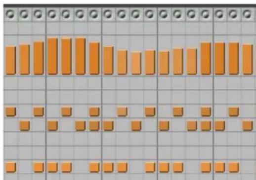
Figure 35-5: The Drum Editor grid.
Notation Editor
The Notation Editor provides a conventional music notation display for a single MIDI track, where MIDI notes are displayed on a single grand (piano) staff. The notes do not have engraver spacing; instead, the spacing is linear to allow for the time ruler above the notation and the controller graph below. This is the only window that displays notation and MIDI controller data side by side. See chapter 42, “Notation Editor” (page 473).

Figure 35-6: The continuously scrolling grand staff in the Notation Editor.
QuickScribe Editor
The QuickScribe Editor provides a WYSIWYG (“What You See Is What You Get”) music notation display. Multiple tracks can be displayed as a conventional music score with natural-looking, engraver spacing on a virtual page, exactly the way they will print out when you print the score. QuickScribe also supplies musical symbols, text insertion and page formatting features for score printing. See chapter 43, “QuickScribe Editor” (page 479).

Figure 35-7: The QuickScribe Editor.
Waveform Editor
The Waveform Editor is a specialized window dedicated entirely to audio editing on individual audio files. It's like having hundreds of dollars of waveform editing software built in to Digital Performer. The Waveform Editor is ideal for mastering applications. See chapter 44, "Waveform Editor" (page 525).

Figure 35-8: Audio data in the Waveform Editor.
EDIT WINDOWS BY TRACK TYPE
The table below lists the types of tracks in Digital Performer and the edit windows available for each:
| MIDI Tracks | Audio Tracks | Conductor Track | Movie Track | |
| Sequence Editor | √ | √ | √ | √ |
| Tracks Window | √ | √ | √ | |
| Event List | √ | √ | √ | |
| MIDI Editor | √ | √ | ||
| Drum Editor | √ | |||
| Notation Editor | √ | |||
| QuickScribe Editor | √ |
OPENING EDIT WINDOWS
There are several ways to open editors:
Location What to do
| From the Consolidated Window | Press the appropriate tab. |
| From the Tracks window Double-click the track name with the appropriate modifier key, as determined by the Preferences in the Digital Performer menu (macOS) or Edit menu (Windows). See “Opening an edit window for a track” on page 181. | |
| From the Tracks window or Sequence Editor | Select the track (or tracks) you wish to edit, and from the Project menu, choose the desired editor. |
From other edit windows Choose desired editor from the mini-menu.
VIEWING MULTIPLE TRACKS IN ONE EDIT WINDOW
The number of tracks that can be viewed in an editor window varies by the type of editor.
Editors that display only one track at a time
Some edit windows display only one track at a time. They are:
■ The Event List
■ The Notation Editor
■ MIDI Editor (see "Exceptions" below)
Editors that display one or more tracks
These edit windows can display one or more tracks at a time:
■ Tracks list
■ Sequence Editor
■ MIDI Editor (see "Exceptions" below)
- Drum Editor
■ QuickScribe Editor
Exceptions
If you prefer to have a separate MIDI Editor for each MIDI track, instead of displaying all MIDI tracks in the same MIDI Editor window, there is a preference for this. See “MIDI Editor options” on page 92.
The track selector list
Edit windows that display more than one track at a time provide a collapsible track selector list on the bottom left-hand side of the window that lets you show or hide the desired tracks in the window.
Click a track name to show (select) it or hide (deselect) it. Option/Alt-click to hide all except the one you click; Command/Ctrl-click to show all except the one you click. Drag across several adjacent tracks to show or hide them.

Figure 35-9: The Track Selector list lets you show and hide tracks in editors that display multiple tracks. Shown here is the MIDI Editor.
Track folders in the track selector
You can click track folders to show or hide the entire folder. Click the disclosure triangle of a track folder to show or hide the tracks (and sub-folders) contained in the folder:

Figure 35-10: Nested track folders in the track selector.
The track selector list and soloing
If the Solo frontmost edit window option is enabled (Figure 23-1 on page 223), then showing and hiding tracks with the Track Selector also affects whether they are soloed or not when solo mode is engaged.
Master track selector
The Drum Editor and MIDI Editor have an additional element in the track selector list: the master track selector. The master track selector controls which track's controller data is currently being displayed in the median strip and controller grid in the window. It also affects note insertion with the Pencil tool, loop insertion with the Loop tool and other tasks that apply to a single track only. Click the master track selector next to the track name to make it the master track.

Figure 35-11: Master track selector in the track selector list.
Track Selector
The Track Selector window is a Track Selector list which is available as a separate window that updates its contents to the active Edit window. For more information, see “Track Selector” on page 364.
VIEWING THE SAME TRACK IN MULTIPLE EDIT WINDOWS
Digital Performer allows you to display the contents of a track in multiple edit windows at the same time. For example, you could view a drum track in the event list and drum editor at the same time. Or you could view a piano track in the QuickScribe, Graphic, and Sequence Editors. When you select an event in one window, it becomes selected in all windows (see “Selections are global” on page 548). Any edits or modifications you make in one edit window are immediately reflected in all other windows. Think of the edit windows as different ways of viewing the same data in the track.
WINDOW TARGET
In edit windows that display one track at a time, the Window Target tab displays the name of the track. In edit windows that display multiple tracks at once, the Window Target tab displays the name of the sequence.
Switching to a different track
In edit windows that display one track at a time, you can switch to a different track in the same window. To do so:
1 Click the Window Target tab in the title bar.
A menu appears as shown below.

Figure 35-12: Click the Window Target menu to use the menu to move from track to track within the same window.
2 Choose the desired track.
The contents of the window changes to the track you select.
Switching to a different sequence
In graphic edit windows that display two or more tracks at a time, such as the Sequence Editor, you can switch to a different sequence in the same window using the same technique as just described: click on the Window Target tab.
EDIT WINDOW MINI-MENUS
This section covers mini-menu commands that are common to all editors. For mini-menu commands that are specific to a specific type of editor, refer to its chapter.

Figure 35-13: Edit window mini-menu commands
Scroll To Counter
Scrolls the editor window to the time currently displayed in the Counter.
Scroll To
Scrolls the editor data display to a time you specify.
Reinsert
Inserts another event that is the same type as the last one you inserted.
Other editors
Choose the desired editor to open it. If you do so from an editor that displays one track at a time (such as the Event List), the chosen editor window will open for the same track.
INFORMATION WINDOWS
The Information Windows — Snap, Cursor, Selection, Event, and Sound File — are windows shared by all Edit windows to provide information about the current cursor position, grid settings, selected event, selection range, and so on. The information displayed in these windows can also be configured to be displayed in a strip across the top of the Edit window, called the Information Bar. For more information, see chapter 37, "Information Windows" (page 355).
LEGEND
The Legend (Setup menu) is a window that shows what each kind of MIDI event is named, and what it looks like in the Event List and info windows. For further explanation of each type of event, see “Types of events” on page 439.
Changing icon colors
To change the color of an icon, click it in the Icon column to open the standard color picker.
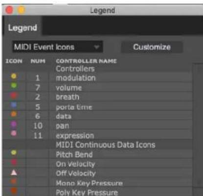
Figure 35-14: The Legend window provides a handy reference for learning the icons that represent each type of data in the Event List.
RELATED TOPICS FOR EDITOR WINDOWS
Scrolling during playback
All edit windows can scroll during playback and recording, and there are various settings that govern scrolling. See “Auto scroll” on page 226.
Selecting data in edit windows
Before you can modify data in an edit window, you must first select it. There are many powerful and convenient ways to do so. See chapter 45, "Selecting" (page 547).
Showing and hiding data with the View Filter
The View Filter lets you temporarily hide data in edit windows by data type, allowing you to focus on and edit only the data types you wish. See chapter, "View Filter" (page 328).
Zooming
Digital Performer has a variety of ways to zoom its windows to show you the finest level of detail, or a bird's eye view. See “Zooming” on page 331.
CHAPTER 36 Tools
OVERVIEW
Tools are available in the Tool palette (Studio menu) and in the Main and Alternate Tool menus in the Control Panel (Figure 22-1 on page 196). Tools are used for inserting, selecting, editing, reshaping, zooming, looping and scrubbing data in Digital Performer's various graphic and notation editing windows, including the Sequence Editor, MIDI Editor, Drum Editor, Notation Editor, QuickScribe Editor, and Waveform Editor.
Main and Alternate Tools ....347
Rotating the Tool palette ....348
Palette docking....348
Closing the Tool palette....348
Keyboard shortcuts for tools....348
Pointer tool....349
I-Beam tool 349
Pencil tool....350
Insert/Reshape Curve....350
Reshape tool 350
Reshape Mode menu....350
Rhythm Brush....351
Zoom tool....351
Scrub tool....352
Mute tool 352
Scissors tool....352
Trim tool 353
Roll tool....354
Slip tool 354
Slide tool....354
Comp tool....354
Velocity tool....354
Hand tool....354
MAIN AND ALTERNATE TOOLS
The Main and Alternate Tool menus in the Control Panel (Figure 22-1 on page 196) let you choose two different tools that you can quickly switch between using a keyboard shortcut, to avoid repetitive trips to the Tool palette. See "Primary and alternate tools" on page 217.

ROTATING THE TOOL PALETTE
The Tool palette can be rotated to a vertical orientation by pressing Shift-Option/Alt-tilde (\~).

Figure 36-2: Press Shift-Option-tilde (\~) to toggle the Tool palette between a horizontal and vertical orientation.
PALETTE DOCKING
There are two preferences in the Preferences command in the Digital Performer menu (macOS) or Edit menu (Windows) for the Tool palette that allow you to dock the Tool palette to the edge of edit windows, either vertically or horizontally. See “Tools” on page 93.
CLOSING THE TOOL PALETTE
Press Shift-O, or click the close button in the upper left corner of the Tool palette title bar.
KEYBOARD SHORTCUTS FOR TOOLS
Hold down the following keys for tool selection:
Command Keyboard shortcut
| Pointer tool A | |
| I-Beam tool I | |
| Pencil tool P | |
| Reshape tool R | |
| Rhythm Brush tool E | |
| Zoom tool Z | |
| Scrub tool S | |
| Mute tool M | |
| Scissor tool C | |
| Slip tool , (comma) | |
| Slide tool . (period) | |
| Roll tool | ‘ (apostrophe) |
| Trim tool / | |
| Comp tool | B |
| Velocity tool | V |
| Hand tool | G |
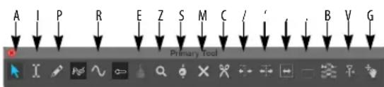
Figure 36-3: Tool shortcuts.
Tool shortcuts can be "sticky"
If you double-tap the keys shown in the tool shortcuts shown above in Figure 36-3, the tool will remain selected until you select another tool.
Cycling tools
Shift-tilde ( ) cycles to the next tool.
POINTER TOOL

The Pointer tool produces the standard 'cross-hair' selection cursor for 'marquee' selections over multiple events and and 'finger' selection cursor for selecting and editing individual events. For example, you could select several measures of notes by positioning the cross-hair cursor over an empty portion of the data grid and dragging out a selection box over the desired events. Here's a summary:
To do this: Do this with the Pointer tool:
| To select an event Click it with the ‘finger’ cursor. | |
| To select several events Shift-click each one. | |
| To select a region of events Drag a selection box over them with the cross-hair cursor. To get the cross-hair, position the cursor over an empty cell. | |
| To select all events within a time range | Drag in the time ruler. |
| To duplicate an event Option/Alt-drag it. | |
| To move an event Drag it with the finger cursor. | |
| To move several events together | Select them, grab one with the finger tool and drag. |
| To change the duration of a note (only available where note durations are displayed) | Position the cursor over its right edge until you see the ‘hand’ cursor and then drag it. |
The Pointer tool can use different selection modes, which will change what kinds of selections are made in some places; see “Choosing a Pointer tool selection mode” on page 548.
I-BEAM TOOL

The I-Beam tool allows you to make time range selections in any graphic editor, regardless of the material you are
dragging over to make the selection. Time range selections in the Sequence Editor are much easier with this tool, especially when you are making selections that begin in the middle of soundbites. As usual, you can hold down the Shift key while using the I-Beam tool to extend or shorten the current selection. Shift-click other tracks to add them to the current selection without changing the start and end times. To make a time range selection that matches the duration of a soundbite or MIDI note, double-click the soundbite or note with the I-Beam. To temporarily get the I-Beam cursor when another tool is selected, hold down the “i” key.
Here are some further details about double-clicking with the I-Beam to create time range selections.
Selecting soundbites with the I-Beam tool
If, using the I-Beam tool, you double-click a portion of a soundbite that is partially covered by other soundbites, you'll select the entire soundbite, even the parts that are covered. However, if you hold down the Option/Alt key while double-clicking it with the I-Beam tool, you'll only select the portion of it that you clicked, as determined by soundbites that cover it on either side of where you click.
Selecting MIDI notes with the I-Beam tool
If you double-click a MIDI note with the I-Beam cursor in a MIDI Editor, you aren't really double-clicking the note itself. Instead, you are clicking a location in time for all pitches in the track. Doing so creates a time range selection that is determined by any notes of any pitch whose duration crosses the time location you clicked.
Here's an example: if you double-click a MIDI note in a MIDI Editor, you'll get a time range selection in the track that matches the duration of the note. If the note's duration overlaps the duration of another note (of the same pitch or a different pitch), then you can double-click it with the I-beam tool in two places: where it overlaps, or where it doesn't overlap. If you double-click where it overlaps, you'll get a time range selection that includes the durations of both notes. If you double-click where it doesn't overlap, you'll get a time range selection of just the note you clicked.
I-Beam cursor
Click the I-Beam tool at any location in any graphic editor to place an I-Beam cursor (flashing vertical line) wherever you click. The I-Beam cursor serves two basic purposes:
■ An insertion point for a paste or merge operation
■ An anchor point for selection commands
For further information about making selections with the insertion point, see “Initiating time range selections with an insertion point” on page 555 and “Modifying a time-range selection using the computer keyboard” on page 555.
Getting an insertion point in an event list
To get an insertion point in an event list, click the line that separates two items in the list. The line will begin to blink. You can insert an event at that location (one tick after the event above the insertion point).
PENCIL TOOL

The Pencil tool lets you insert data using the following techniques:
To do this: Do this with the Pencil tool:
| To insert an event Click in a note grid or continuous data grid. | |
| To remove a MIDI note Click it on a MIDI note grid. | |
| To insert continuous data curve (MIDI or audio) | Click the master track button for the desired track, if any, click the Pencil tool, choose the desired shape from the in the Tool palette, choose the desired data type in the continuous data grid (or make it the active layer in the Sequence Editor) and then click or drag on the grid. |
| To edit audio pitch automation | Click and drag on the audio pitch display. |
To edit samples in the Waveform Editor
Click them or drag over them.
The Pencil tool settings in the Drum Editor
When inserting notes in the Drum Editor, the Drum Editor Tool Settings Pane shows the settings for inserting notes For details, see “The Pencil settings” on page 467.
INSERT/RESHAPE CURVE

Controls the shape or curve of continuous data when you insert it with the Pencil tool or modify it with the
Reshape tool. For complete details, see “Inserting continuous data in Points or Bars mode” on page 427 and “Reshape tool”, below.
RESHAPE TOOL

The Reshape tool lets you reshape a stream of continuous data. For complete details, see “Reshape Mode menu”. The
techniques can be used in any continuous data grid, including volume editing mode for audio and MIDI tracks in the Sequence Editor.
Using the Reshape tool in the Drum Editor note grid
In the Drum Editor, the Reshape tool can also be used to modify velocities in the note grid. See “The Reshape tool” on page 467.
RESHAPE MODE MENU

Digital Performer provides several powerful ways to reshape continuous data curves.
A variety of reshape modes are available, as shown below:

Figure 36-4: Choosing a reshape mode.
Here is an explanation of each reshape mode.
Reshape mode What it does
| Set Forces data values to exactly match the curve that you draw. |
| Add Adds or subtracts a fixed amount to all data values based on how far above or below the origin you draw the reshape curve. Draw above the origin to add; draw below it to subtract. |
| Scale Scales all data values based on how far above or below the origin you draw the reshape curve. Draw above the origin to scale up; draw below it to scale down. |
| Max limit Lowers all data values that are above the reshape curve. |
| Min limit Raises all data values that are below the reshape curve. |
You can reshape any kind of continuous data, such as MIDI continuous controllers, audio volume automation, etc. To reshape a stream of continuous data, in this example a MIDI CC:
1 Click the Reshape tool in the Tool palette.

2 Choose the desired shape of the curve from the Pencil/Reshape Curve menu in the Tool palette (Figure 36-4 on page 351).
3 Drag over the data you wish to reshape, as demonstrated below in Figure 36-5.

natural_image
Two abstract waveforms with dotted patterns, no text or symbols presentFigure 36-5: In this reshape example, a stream of volume controllers are being scaled with the sine wave reshape tool.
RHYTHM BRUSH

The Rhythm Brush can only be used in the Drum Editor. (It is grayed out when another editor window is active.) The
Rhythm Brush lets you quickly 'paint' in drum parts in a wide variety of percussion instrument styles. For complete details, see "The Rhythm Brush tool" on page 467.
ZOOM TOOL

The Zoom tool (magnifying glass) in the Tool palette lets you zoom in on a portion of a graphic editor by dragging a zoom
box over it. Click to zoom in and Option/Alt-click to zoom out. In the time ruler or continuous data grid, drag horizontally to zoom the time axis only.
natural_image
Pure electrical circuit lines without any symbolsFigure 36-6: Zooming with the Zoom tool.
Zoom tool shortcuts
Here are some zooming shortcuts:
Shortcut What it does
| Click once To zoom in horizontally. | |
| Option/Alt-click To zoom out horizontally. | |
| Shift click To zoom backward through zoom history | |
| Shift-control click To zoom forward through zoom history | |
| Drag in the time ruler To fill the window with the region you select without affecting the pitch zoom | |
| Drag over an area in the note grid | To zoom time and pitch simultaneously |
| Option/Alt-click the zoom out button | To zoom all the way out |
| Option/Alt-click the zoom in button | To zoom all the way in |
| Command/Ctrl-click the zoom buttons | To toggle between the last two zoom levels |
For other zooming features and shortcuts, see "Zooming" on page 331.
SCRUB TOOL

The Scrub tool lets you scrub data as follows:
To scrub this: Do this:
| MIDI notes in the MIDI Editor or Drum Editor | Drag horizontally in the note grid. Only notes in tracks that are currently being displayed in the grid are scrubbed. (To scrub all play-enabled tracks, drag the playback wiper.) |
| A soundbite in the Sequence Editor | Make sure the track is displaying soundbites, and then scrub directly on the soundbite. |
Audio waveform data in the Scrub anywhere on the waveform. Waveform Editor
MUTE TOOL

The Mute tool mutes and unmutes soundbites or MIDI notes when you click them or drag over them in the Sequence
Editor or Track Overview. The Mute tool only works when soundbites or MIDI notes are the active layer in the track. Muting occurs independently of any volume automation in the track. Muted soundbites appear with a grayed-out waveform; muted MIDI notes appear as grayed out notes.
The Mute tool is a handy way to temporarily mute soundbites or notes, but it is also great for arranging and creating interesting rhythm parts. Here's just one example: use the Scissors tool to split an ambient pad into a rhythmic grid of slivers (explained further in the next section) and then use the Mute tool to quickly create syncopated riffs by muting various combinations of the slivers. To temporarily get the Mute tool when another tool is selected, hold down the "M" key. The same technique could be used on a MIDI drum loop or phrase of any kind.
In the Waveform Editor Beats tab, the Mute tool can be used to disable or enable individual beats.
SCISSORS TOOL

The Scissors tool splits a MIDI note or soundbite where you click. With the edit grid turned on, you can also drag across a
note or soundbite to split it repeatedly on grid lines, as demonstrated below in Figure 36-7. To temporarily get the Scissors tool when another tool is selected, hold down the “C” key.
Before:
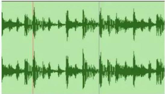
natural_image
Green audio waveform visualization with no text or symbolsAfter:

line
| Time | Speed | |------|-------| | 0 | 0 | | 1 | 0 | | 2 | 0 | | 3 | 0 | | 4 | 0 | | 5 | 0 | | 6 | 0 | | 7 | 0 | | 8 | 0 | | 9 | 0 | | 10 | 0 | | 11 | 0 | | 12 | 0 | | 13 | 0 | | 14 | 0 | | 15 | 0 | | 16 | 0 | | 17 | 0 | | 18 | 0 | | 19 | 0 | | 20 | 0 | | 21 | 0 | | 22 | 0 | | 23 | 0 | | 24 | 0 | | 25 | 0 | | 26 | 0 | | 27 | 0 | | 28 | 0 | | 29 | 0 | | 30 | 0 | | 31 | 0 | | 32 | 0 | | 33 | 0 | | 34 | 0 | | 35 | 0 | | 36 | 0 | | 37 | 0 | | 38 | 0 | | 39 | 0 | | 40 | 0 | | 41 | 0 | | 42 | 0 | | 43 | 0 | | 44 | 0 | | 45 | 0 | | 46 | 0 | | 47 | 0 | | 48 | 0 | | 49 | 0 | | 50 | 0 | | 51 | 0 | | 52 | 0 | | 53 | 0 | | 54 | 0 | | 55 | 0 | | 56 | 0 | | 57 | 0 | | 58 | 0 | | 59 | 0 | | 60 | 0 | | 61 | 0 | | 62 | 0 | | 63 | 0 | | 64 | 0 | | 65 | 0 | | 66 | 0 | | 67 | 0 | | 68 | 0 | | 69 | 0 | | 70 | 0 | | 71 | 0 | | 72 | 0 | | 73 | 0 | | 74 | 0 | | 75 | 0 | | 76 | 0 | | 77 | 0 | | 78 | 0 | | 79 | 0 | | 80 | 0 | | 81 | 0 | | 82 | 0 | | 83 | 0 | | 84 | 0 | | 85 | 0 | | 86 | 0 | | 87 | 0 | | 88 | 0 | | 89 | 0 | | 90 | 0 | | 91 | 0 | | 92 | 0 | | 93 | 0 | | 94 | 0 | | 95 | 0 | | 96 | 0 | | 97 | 0 | | 98 | 0 | | 99 | 0 | | Note: The actual values in the CSV data will vary each time the code is run due to the use of random data. The provided values are just an example from the visual encoding. There is no label for the output.Figure 36-7: Turn on the edit grid and drag across a MIDI note or soundbite to split it repeatedly along edit grid lines.
TRIM TOOL

The Trim tool allows you to trim soundbites and continuous data. To temporarily get the Trim tool when another tool is selected, hold down the forward slash key (/).
Soundbites
With the Trim tool chosen, click anywhere in a soundbite to move the right edge to the location where you clicked. Hold down the Option/Alt key to move the left edge of a soundbite.
Continuous data
The Trim tool can also be used on continuous data, such as audio track volume, MIDI CCs, and pitch bend.
When the Trim tool is chosen and the mouse is directly over continuous data, the Trim tool cursor will change to a hand with a pointed finger. You can click on a data point, or on the line segment between data points, and drag it up or down to trim its value.

Figure 36-8: Trimming continuous data
If there is a time range selection or event selection of continuous data, clicking and dragging on one of the selected line segments or data points will move all of the selected data.
Scaling continuous data
A selection of continuous data can also be scaled with the Trim tool. When there is a time range or event selection of continuous data, move the cursor within the selection (but not directly over a point or line segment) then click and drag up or down.

Figure 36-9: Scaling continuous data
Points are automatically added at the boundaries of the selection to preserve the data before and after the selection.
Flattening continuous data
Holding the Option/Alt key while using the Trim tool as described above will flatten the data rather than scale it.

Figure 36-10: Flattening continuous data
ROLL TOOL

The Roll tool allows you to edge edit the beginning of one soundbite and the end of another where they abut each other.
They must be touching one another. To temporarily get the Roll tool when another tool is selected, hold down the apostrophe key (').
SLIP TOOL

The Slip tool allows you to edge edit the start and end of a soundbite while the soundbite remains at the same position in
the track. The soundbite's length does not change. To temporarily get the Slip tool when another tool is selected, hold down the comma key (,).
SLIDE TOOL

The Slide tool allows you to move a soundbite in the sequence while leaving the soundbite's audio at the same
playback time. This is the same as edge editing both ends by the same amount forwards or
backwards. To temporarily get the Slide tool when another tool is selected, hold down the period key (.).
COMP TOOL

The Comp tool allows you to create a composite, or "comp," take from multiple takes in an audio track. To temporarily get the Comp tool when another tool is selected, hold down the "B" key. See chapter 51, "Takes and Comping" (page 665).
VELOCITY TOOL

The Velocity tool allows you to click on a MIDI note and drag up or down to adjust its velocity. You can also swipe
horizontally in the continuous data grid in the MIDI Editor or the note velocity lane in the Sequence Editor to adjust multiple note velocities in a single gesture.
HAND TOOL

The Hand tool allows you to scroll graphic editors smoothly and precisely. It also lets you scroll vertically and
horizontally in a single gesture. Simply click anywhere in the graphic editor grid and drag as desired.
CHAPTER 37 Information Windows
Overview
The Information windows provide feedback about a wealth of parameters, events, controls, and more. Each Information window has its own particular display or purpose, but they all behave similarly in several ways:
■ The contents of the Information windows update to the current window, selection, cursor position, etc. while you work; in this way, they serve as central locations for feedback about your project.
■ The exact information displayed in a window may change depending on choices made in the Time Formats window. See “Time Formats window” on page 100.
- When popped out of the Consolidated Window, the Information windows "float" (except for the Sound File Information window).
■ The key command associated with each Information window (except for the Sound File Information window) is a show/hide toggle: press the key command once to show the window, then press it again to hide the window.
Snap Information....355
Cursor Information 358
Event Information....359
Selection Information ....359
Track Inspector....361
Channel Strip....362
Track Selector ....364
Sound File Information 365
Information Bar ....367
SNAP INFORMATION
The Snap Information window contains information pertaining to snapping and nudging.

Figure 37-1: The Snap Information window.
Snap to Grid
The Snap to Grid feature can be enabled or disabled with the check box provided. If the Snap to Grid box is turned on, data snaps to the edit grid. If it is turned off, data doesn't snap to grid. Choose the desired Snap to Grid mode from the menu (Figure 37-1): Fixed or Auto.

Figure 37-2: Snap to Grid.
Auto mode
In Auto mode, Digital Performer chooses a reasonable grid size, based on the time format of the time line and the zoom level of the edit window you are working in. For example, if you are zoomed in quite a bit for detailed editing, the Auto grid might snap to 32nd notes. If you zoom out, it will snap to 16th or 8th notes.
Fixed mode
In Fixed mode, the Unit = setting (Figure 37-1) determines the minimum time unit for editing, which is shown as a note duration and a number of beats and ticks, such as 240 ticks. The Edit Grid Resolution (Unit =) determines the amount of time between grid points. MIDI events, note durations, soundbites, loops, region boundaries, automation data, Memory Cycle repeat barlines, or any event that can be dragged horizontally will snap to time increments in the time line equal to the value of the edit grid unit. For example, if the Unit is set to 120 ticks, events will snap to 000, 120, 240 and 360 ticks.
Using Snap to Grid
Choosing between Fixed and Auto modes is a global setting for all edit windows. However, Snap to Grid's on/off state, the edit grid resolution and Snap Relative's on/off state can be set independently for each edit window, except that:
■ It does not affect the Event List.
■ You can change the edit grid resolution in the Drum Editor, but because of its grid-based display, Snap To Grid is always enabled.
If you wish to maintain an event's original, unquantized position relative to the time line's absolute grid, use the Snap Relative option. See "Snap Relative" on page 357.
Setting the Edit Grid Resolution
To change the Edit Grid Resolution, first make sure that Fixed mode is chosen from the menu and then use the value field provided to type in the desired grid duration, or choose a preset length from the Unit= menu.
When you type in a value, the note displayed next to the ticks box will grey out (or text will be displayed in italics) if the tick value does not equal one of the presets in the menu.
Triplet and dotted triplet grid editing
The edit grid menu also provides choices for triplet and dotted triplet values.

Figure 37-3: The edit grid menu for measures and beats provides triplet and dotted triplet values.
Edit grid supports all time formats
The Time Format command (Setup menu) lets you choose any time format you wish for the edit grid (measures, frames, real time or samples). For example, if you choose SMPTE frames as the global time format, the Edit Grid switches to frame time, and grid editing can be done at SMPTE time code increments such as one frame, 10 frames, etc. A significant by-product of this feature is that the real-time grid, SMPTE frame grid and sample edit grid preserve the real-time relationship of events with respect to each other during edits. For example, if you move several sound effects events to a location in the sequence that is at a different tempo, their spacing with respect to one another will not expand or contract due to the different tempo; instead, their relation to one another will be maintained. This is similar to the editing behavior in locked tracks.

Figure 37-4: The Time Format window affects the edit grid, allowing you to edit it SMPTE frames, real time values (such as milliseconds) and even samples.
When the edit grid is set to any time format other than measures and beats, the Smart Selections feature (Edit menu), which provides assisted measure- and beat-relative editing operations, is automatically disabled (since you have no measures or beats to refer to during edits).
Snap to Grid and selecting
Snap to Grid applies to selection, too, so it is an effective way to constrain selection operations.
Edit resolution when the grid is turned off When Snap to Grid is turned off, data can be dragged freely. The smallest unit of resolution is one screen pixel, the exact resolution of which is determined by the current zoom level.
Temporarily overriding Snap to Grid
The Command/Ctrl key temporarily overrides the current Snap to Grid enable/disable state. For example, if Snap to Grid is currently enabled, the holding down the Command/Ctrl key while dragging overrides the current edit grid.
Conversely, if Snap to Grid is currently disabled, the Command/Ctrl key forces dragging to snap to the current Snap to Grid grid setting. The same is true for selection operations.
Don't let the edit grid fool you
When you zoom in, the edit grid (in Fixed mode) may cause data to seem like it is “stuck”; that is, data will not move when you try to drag it. This is because the fixed-size edit grid is larger than the distance you are dragging. To “unstick” the data, deselect the Snap to Grid check box, or hold down the Command/Ctrl key while dragging. Doing so overrides the edit grid temporarily. Alternately, you can use “Auto mode” on page 355.
Snap to Grid and nudging with the arrow keys Snap to Grid only affects dragging operations. It is independent of nudging data with the arrow keys (except when Nudge is set to Use Edit Grid – see “Nudge” below).
Displaying edit grid lines
You can display lines extending downwards from the time ruler through the data grid to indicate the current edit grid. See “Edit Window guides” on page 91 for details.
Snap to Beat
Snap to Beat (Figure 37-1 on page 355) snaps actions to the beats within the waveform. This is active only when in the Sequence Editor or Waveform Editor. See “Using the beat grid” on page 690. Similar to grid snapping, the Command/Ctrl key temporarily overrides the current Snap to Beat enable/disable state.
Snap to Markers
When Snap to Markers is checked (Figure 37-1 on page 355), dragged events snap to markers. The edges of soundbites and MIDI notes dragged close to a marker location also snap to the marker's time. For example, the left edge or right edge of a soundbite or MIDI note will snap. Snapping also occurs when spotting soundbites by dragging them from the Soundbites window into the Sequence Editor.
You might find it helpful to turn off the Edit Grid and show marker grid lines (by checking the Show Marker Grid Lines MIDI Editors preference). Marker snapping is not affected by the display of marker grid lines (“Showing marker grid lines” on page 379): they can be shown or hidden and snapping will still occur (when it is turned on).
Hold down the Command/Ctrl key to toggle the current setting.
Snap Relative
When Snap Relative (Figure 37-1 on page 355) is checked, an event moves relative to its original position, rather than snapping to the time line's absolute grid. For example, if the grid unit is set to
120 ticks, and the original event is located at 013 ticks, it will snap to 133, 253, and 373 (which are all 13 ticks after 000, 120, 240 and 360).
Nudge
The Nudge amount (Figure 37-1 on page 355) lets you to choose the unit of time by which you can nudge any selected data with the arrow keys. Many different time formats are supported, including SMPTE frames, SMPTE sub-frames, samples, and milliseconds. Choose the desired time format from the menu and then enter the amount of time. You can change the nudge amount at any time.

Figure 37-5: Setting the Nudge Amount.
When you choose a mensural time format (one that involves measures, beats and/or ticks), data is nudged in the same manner as using the Shift command (Edit menu) with the Preserve Real-time Performance option unchecked. This means that the data being nudged maintains its metrical relationship to the sequence, changing the way it plays back, if necessary, to respect any tempo changes that may be programmed in the conductor track in the area in which the data is being nudged.
When you choose any other time format (real time, SMPTE frames, sub-frames, milliseconds, or samples), the real time performance of the data is preserved, regardless of any tempo changes. When you choose the Use Edit Grid menu item, the nudge amount is determined by the edit grid setting above. If the edit grid is currently disabled, then nudging occurs in the same manner as in the window itself (by one screen pixel). In the Tracks window, the column duration determines the nudge amount.
CURSOR INFORMATION
The Cursor Information window displays the current location of the mouse cursor with respect to the horizontal and vertical axis in the edit windows. Values in this box are continually updated as the mouse cursor moves around the edit window, giving you immediate, numerical accuracy when inserting and manipulating data with the mouse.

Figure 37-6: The Cursor Information window
Time
The pointer's horizontal coordinate, Time, displays the time of the current cursor location. It is displayed in the time formats chosen in the Time Formats window – see “Customizing the cursor coordinates display” below.
Value
The cursor's vertical coordinate, Value, depends on its location, and in the Sequence Editor, the active layer. It will display MIDI note values when the cursor is over a MIDI note grid, controller values when over a continuous data grid, audio volume when over audio track volume automation, soundbite names when over soundbites, and so on.
| Time | 121373 | |
| Pitch | B2·59 | |
| Time | 121279 | |
| Modulation | 70 | |
| Time | 131194 | |
| Soundbite | 085a | |
| Time | 131107 | |
| Volume | -8.50 | |
Figure 37-7: The vertical value of the cursor updates to the type of data under the cursor
Cursor Info in the Waveform Editor
Additional fields are shown in the Cursor Information window when the Waveform Editor is the active window. See “Cursor Information” on page 530.
Customizing the cursor coordinates display
Use the Cursor Information section of the Time Formats window in the Setup menu (Figure 8-6 on page 101) to specify the time and pitch formats you wish to display.
Any combination of the available time formats can be enabled. For example, you may wish to see both measures and SMPTE frame time, or perhaps all four time formats at once.
EVENT INFORMATION
The Event Information window displays numerical details about a single event that has been selected. This displays data in the same way as it appears in the Event List. For example, a selected note appears with its location, pitch, on velocity, off velocity, and duration.

Figure 37-8: When you click a note, its numerical information can be displayed and edited in the Event Information window.
When a soundbite is selected, additional information is displayed: soundbite mute, original timestamp, user timestamp, bite gain, tempo, and time signature.

Information displayed in the Event Information section can be edited by clicking it (with the exception of some soundbite attributes). The same editing conventions as the Event List apply, such as using the Tab key and arrow keys to move from field to field and press return to confirm any changes you have made. The event's graphic display will change to reflect the modifications.
SELECTION INFORMATION
The Selection Information window holds the start and end times for any region that you wish to edit in any currently highlighted tracks. If the Digital
Performer project file contains multiple chunks (sequences and/or songs), separate Selection Information is stored for each chunk.
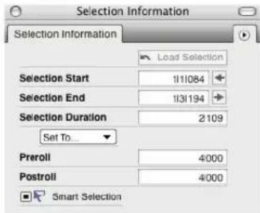
Figure 37-9: The Selection Information window.
You can set these times by:
■ making a time range selection in an edit window
■ typing (use the Tab key as usual)
■ dragging on the numbers vertically to change them
■ choosing the desired command from the Set To menu
■ using several clicking shortcuts
■ using several keyboard shortcuts
■ loading them with the Remember Times Command
These techniques are discussed in the following sections.
Editing the selection bar numbers directly
To enter a start or end time, click in a field and enter a value. You can use the Tab key (or decimal point key on the keypad) to cycle through the measure|beat|tick fields. Or you can simply press on any field and drag up or down to change its value.
Using the Set To menu shortcuts
The Set To menu holds several great shortcuts for loading times into the Selection Information window:

| Set to Selection Bounds |
| Set to Chunk Rounds |
| Set to Remembered Times |
| Set Start to Counter |
| Set End to Counter |
| This part |
| That part |
| New Saved Time... |
| New Saved Time For This Chunk... |
| Edit Saved Times... |
Figure 37-10: The Set To menu provides several useful shortcuts for entering start and end times in the Selection Info window.
Command What it does
| Set to Selection Bounds Loads the beginning and end of the currently selected region into the Selection Information window. |
| Set to Chunk Bounds Loads the very beginning and end of the entire sequence. |
| Set Start to Counter Loads the current counter location into the start time. |
Set End to Counter Loads the current counter location into the end time.
For the last two commands, Digital Performer loads the counter location at the time you click the menu, not when you actually choose the command. This helps you load start and end times on the fly during playback. Click the menu at the desired instant, and then take as much time as you need to choose either Set Start or Set End.
Clicking the start and end buttons
The buttons to the right of the Selection Start and Selection End values let you load times as follows:
Click the button to load the current counter location - even on the fly during playback.
Command/Ctrl-click the button to load the beginning or end of the sequence into the start time or end time, respectively.
Control/Win-click the button to load the beginning or end of the Remembered Times (previously retrieved from a selection with the Remembered Times command) into the start time or end time, respectively.
The selection bar shortcuts
There are two shortcuts for loading the current counter location into the Selection start and end times. By default, they are assigned to the F5 and F6 keys on your computer keyboard. You can change these key assignments if you like. You can also program these key commands to respond to any MIDI device, so that you can actually load counter times from an external MIDI device. See chapter 9, “Commands” (page 105) for details.
The "Remember Times" command
The Remember Times command (control-R), allows you to save any time range selection, so that you can load it into the Selection Information window later on. You can also load remembered times into the Memory Bar and the Auto-Record Bar. For complete information, see “The ‘Remember Times’ command” on page 556.
Load Selection
The Load Selection button provides additional shortcuts. Click the Load Selection button once to Set Selection to Remembered Times, or double-click the button to Set Selection to Chunk Bounds.
Making a selection in an edit window
You can make a time range selection in an edit window to set the Selection times. For example, you could click one of the Memory Cycle markers in the MIDI Editor to select the Memory Cycle range. The selection is automatically loaded into the Selection Information window.
Preroll and Postroll
These text fields set the Preroll and Postroll for Link Playback to Memory mode. See “Preroll and Postroll” on page 209.
Smart Selections
A check box is provided as a convenient shortcut to enable or disable Smart Selections. For more information, see "Smart Selections" on page 556.
TRACK INSPECTOR
The Track Inspector window shows track settings such as color, input, output, play-enable status, record-enable status, Pitch mode, Stretch mode, and so on.

Figure 37-11: The Track Inspector window.
As with other Information windows, the Track Inspector may be added to the Info Bar using Preferences > Information Bar. This allows you to add controls for track play-enable, record-enable, take, automation, and so on in windows that did not previously have them available, such as the QuickScribe Editor.

Figure 37-12: The Track Inspector in the QuickScribe Editor Information Bar.
Additionally, the Track Inspector has a mini-menu option to "Use Small Menus in Info Bar" (shown below). By default, this item is unchecked and the menus shown in the Track Inspector's Info Bar section are displayed at their full width.

Figure 37-13: The Track Inspector using small menus
CHANNEL STRIP
The Channel Strip window shows the Mixing Board channel strip controls for a single track. The Channel Strip window updates to focus on the current track at hand.
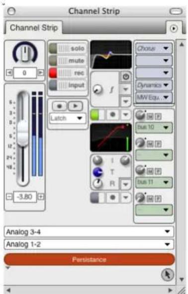
Figure 37-14: The Channel Strip window
The Channel Strip can be configured (via its mini-menu) to display one, two, three, or four columns:

When in two, three, or four column view, the fader defaults to the left side of the window. To reverse the order of the columns, deselect the "Fader on left" mini-menu item.
Additionally, similar to the Mixing Board, you can show and hide sections of the Channel Strip via the mini-menu:
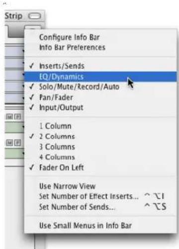
Figure 37-16: Showing and hiding sections in the Channel Strip window
Locking the Channel Strip window
The Channel Strip window normally updates to follow the selected track, but it can be “locked” to display the track of your choice regardless of the selected track. To lock the Channel Strip window to the track currently showing in the Channel Strip, click the lock button beneath the track name; click the icon again to unlock it.

Figure 37-17: The Channel Strip lock
This only affects the Channel Strip window; if you're displaying the Channel Strip in the Information Bar (see below), it will always follow the selected track.
Displaying the Channel Strip in the Information Bar
As with other Information windows, the Channel Strip may be added to the Info Bar using Preferences > Information Bar. This allows you to control a track's fader, pan knob, effect insert, and so on in windows that did not previously have them available, such as the Sequence Editor. You can configure the Channel Strip section differently in each edit window, if desired.
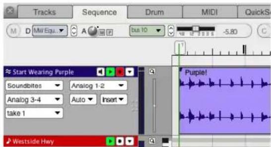
Figure 37-18: The Channel Strip in the Information Bar
The controls function in the same manner as in the Channel Strip window, with the exception that the Inserts and Sends sections display only one insert or send at a time. To change which insert or send is being displayed, click the up/down arrows in each section. A label is shown to the left of the insert or send to indicate which is shown.

Figure 37-19: These controls change which insert or send is shown
Small menus
The Channel Strip has a mini-menu option to "Use Small Menus in Info Bar". By default, this item is unchecked and the menus shown in the Channel Strip's Info Bar section are displayed at their full width.

Figure 37-20: The Channel Strip using small menus
Configuring the Channel Strip When configuring the Channel Strip for the Info Bar (Channel Strip mini-menu > Configure Info Bar), not all of the Channel Strip's controls are shown. This is for two reasons:
1 The EQ and Dynamics sections are not available in the Information Bar.
2 The following controls are added to the Information Bar by way of the Track Inspector:
■ Solo/Mute/Record/Input
■ Automation play/record-enable
■ Input/Output
- Track name
For more information, see "Track Inspector" on page 361.
TRACK SELECTOR
The Track Selector window is much like the Track Selector which is a part of each Edit window. However, rather than being a part of a window, it is a separate window which updates to the current active edit window. In this way, you can use a single Track Selector for all edit windows.
Additionally, since it is a separate window, it can be resized and positioned anywhere on screen, rather than being a fixed size in a fixed location.

Figure 37-21: The Track Selector window.
Track Selector button preferences
You can determine what happens when you click the Track Selector button in an edit window by changing the Track Selector button preference. Open Preferences from the Digital Performer menu (macOS) or Edit menu (Windows) and choose Edit Windows from the list on the left. The Track Selector button has three options:
■ Always open Track Selector window
■ Always open the edit window's Track Selector
■ Opens Track Selector window for editors inside the Consolidated Window
SOUND FILE INFORMATION
Sound File Information window (Studio menu) gives you detailed information about the currently selected soundbite.

Figure 37-22: The Sound File Information window shows information about the currently selected soundbite, its parent sound file, and any sampler loops in the file, if any.
Choosing an audio file, soundbite or loop
To view information in the Sound File Information window, click a soundbite in the Soundbite list or elsewhere to select it. When you do, the Sound File Information window shows information about the currently selected soundbite, its parent audio file, and any sampler loops in the file, if any.
The Sound File section
The Sound File section at the top of the window shows information about the soundbite's parent sound file, such as its location, sample rate, length and the date it was created and last modified.

You can even type in comments about the sound file that are stored with the file itself (so they will appear in this window when you import the audio file into other Digital Performer projects). The menu at the top of the section allows you to switch to a different sound file, if you like.
Soundbite preferences for transposing and time-stretching
As shown in Figure 37-23, the popup menus in the status area at the top of the Soundbites window show the Transpose preference and the Time Compress/Expand preference for the selected soundbite or soundbites. Each soundbite can be assigned its own preference.
To assign the transpose and time-compress/expand preferences to multiple soundbites at a time, select them in the Soundbite list or Sequence Editor and change their setting in the Sound File Info pane. See “Setting sound file prefs for multiple soundbites” on page 366.
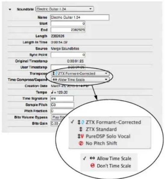
Figure 37-23: Pitch-shifting and time-stretching preferences are found in the Info pane for each soundbite.
The Transpose preference can also be set in the menu directly on the soundbite's title bar in the Sequence Editor (Figure 81-1 on page 935).
Transpose preference
The Transpose preference determines the pitch-shifting algorithm that will be employed when transposing the sound file, whenever audio transposing is employed. Each algorithm is explained in the following sections. For more information about transposing, see chapter 81, "Transposing Audio" (page 935).
Time scale versus don't time scale
There are only two options for the Time Compress/Expand preference: Allow Time Scale and Don't Time Scale. This determines the behavior of the Scale Time, Adjust Soundbites to Sequence Tempo and Stretch commands, as well as beat-based operations such as quantizing beats within soundbites. You may want to mark soundbites that contain a single note or sound effect, for instance, as Don't Time Scale. A soundbite that contains multiple notes, such as a two-measure drum loop, would typically be set to Allow Time Scale, so that its tempo will always match that of the rest of the sequence.
Setting sound file prefs for multiple soundbites
To set the sound file preferences for two or more soundbites at one time:
1 Select the soundbites.
2 Open the Sound File Information window. The Sound File menu will now say "Selected files".
3 Choose the desired preferences in the Soundbite section. If the Soundbite section's details are not visible, click the triangle next to the Soundbite section to expand it.
The Soundbite section
The Soundbite section in the middle of the window shows details about the currently selected soundbite, such as its start time, end time and length (in samples).

The menu at the top of the Soundbite section lets you display the information for any soundbite you wish.
The start, end and length of the soundbite are displayed in number of samples, whereas the Length in Time is a real-time measurement. The Original Timestamp is the location at which the soundbite was originally recorded, if any. This setting, as well as the User Timestamp, are explained further in “Timestamps” on page 651. The Transpose, Time Compress/Expand, Tempo and Time Signature items are the same as the information displayed in the Soundbite list (see “Soundbite preferences for transposing and time-stretching” on page 365). The final two sampler-related details, the Sample Pitch and Pitch Fraction settings, can be useful when you need to transfer the soundbite to a sampler. Bite Volume Bypass lets you bypass or play volume automation data that is associated with the soundbite (see “Soundbite volume automation” on page 407). Bite Gain non-destructively raises or attenuates the overall volume of the soundbite. The range is from -140 to +80 dB. See also “Bite Gain” on page 393.
The Audio Loop section
The Audio Loop section at the bottom of the Info pane provides details about any sample loops in the audio file. Sample loops are the loop points created by samplers (or sampler editors).
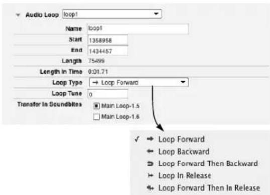
The Loop Type and Loop Tune items refer to the corresponding loop settings in today's samplers. These settings have no effect in Digital Performer.
The Transfer In SoundBites option lets you control which soundbites the loop “belongs” to. Listed are all of the soundbites that encapsulate the loop (i.e. all soundbites that start before it and end after it). When you check the box next to a soundbite, the loop will be included when you transfer that soundbite to the sampler (using Digital Performer’s sample transfer abilities).
INFORMATION BAR
The Information Bar is a configurable strip available in the Tracks Window and each of the Edit windows. It can contain some or all of the information shown in each of the Information windows (excluding the Track Selector and Sound File Information windows).
Information Bar settings
The Information Bar is configured using the Information Bar preferences (Preferences > Information Bar) and the “Configure Info Bar” command (Information window mini-menus).

Figure 37-24: The Information Bar

Showing/hiding the Information Bar
To show the Information Bar for an Edit window, open the Information Bar preferences and enable at least one of the sections for the desired Edit window. To hide the Information Bar for an Edit window, disable all sections.
Configuring the Information Bar
There are two parts to configuring the Information Bar:
■ Choosing which sections are visible
■ Choosing which fields are shown within each section
To choose which sections are visible, open the Information Bar preferences and enable the desired sections.

To choose which fields from the Information windows appear in the Information Bar, open an Information window and choose Configure Info Bar from its mini-menu: the Information window will enter configuration mode.
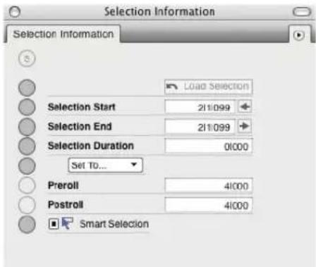
To enable a field so that it will be shown in the Information Bar, check the circle next to the field; to disable a field so that it will not be shown in the Information Bar, uncheck the circle next to the field.
Each window maintains its own configuration of each Info Bar section. For example, you can choose to show Selection Start, Selection End, and Selection Duration in the Selection Information section of the Sequence Editor's Info Bar, but only show Selection Start and Selection End in the QuickScribe Editor's Info Bar.
When an Information window is in configuration mode, you're configuring its appearance in the active window's Information Bar. For example, when the Sequence Editor is focused and the Cursor Info window is open in configuration mode, enabling or disabling a field does so for the Cursor Info section of the Information Bar in the Sequence Editor. If you leave the Cursor Info window in configuration mode and change which edit window is focused, say, from the Sequence Editor to the MIDI Editor, the Cursor Info window will update to the configuration used for the new window. If you wish to enable or disable a field for all windows at once, Option/Alt-click the field's circle.
Using two lines for the Information Bar
The “Use two lines…” option in the Information Bar preferences splits the Information Bar elements into two lines when more than three sections are showing to give each section more room to display its contents.
Opening the Information windows
To open an Information window from the Information Bar, click the circled letter at the left of the section.

Additionally:
■ Option/Alt-clicking the circled letter will open the Information window in configuration mode.
■ Command/Ctrl-clicking the circled letter will open the Information Bar preferences.
CHAPTER 38 Sequence Editor
OVERVIEW
The Sequence Editor is one of several edit windows in Digital Performer. To learn more about editors in general, see chapter 35, “Edit Windows” (page 339).
The Sequence Editor provides a multitrack graphic environment for editing audio tracks and MIDI tracks side by side. It includes a movie track for displaying a project's movie along the same timeline. You can view one or more tracks at a time using Digital Performer's standard track selector to show and hide tracks as desired.
MIDI tracks are displayed with the same graphic note grid as the MIDI Editor, except that continuous data and Median Strip events are overlaid on top of the grid. Similarly, audio tracks display waveform data with automation data overlaying it. You can switch layers in each track independently to bring any type of data to the front for editing.
As with other editors, the Sequence Editor provides sample-accurate editing of MIDI and audio.
The Sequence Editor includes basic track management features, such as adding, duplicating and deleting tracks and sequences. Combined with its MIDI and audio editing features, the Sequence Editor provides “one-stop shopping” for editing and managing a Digital Performer project.
Quick Reference....372
Tool palette quick reference ....375
Sequence Editor mini-menu....376
Sequence Editor basics ....376
Opening the Sequence Editor....376
Sequence Editor title bar....376
Sequence management....377
Track management ....377
Snap, Cursor, Selection, and Event Information ..... 378
The Time Ruler 378
The Marker Strip 378
The Memory Cycle Strip 379
The Auto Record Strip 379
Zoom buttons....379
Zooming techniques....380
Audio track settings 380
MIDI track settings 385
Resizing tracks....386
Working with MIDI tracks 386
Effect inserts panel....387
Audio editing basics....388
Inserting soundbites 389
Moving soundbites 390
Muting and unmuting soundbites ....392
Overlapping and layering soundbites 393
Trimming (edge editing) soundbites 393
Graphic time stretching of audio 396
Applying fades and crossfades 396
Graphic editing techniques ....396
Selection techniques....396
Show times 398
Sync points 399
Working with Clips....400
Working with breakpoint mix automation ....403
Soundbite volume automation....407
Working with event flags....407
The View Filter 408
Scrolling during playback....408
Scrubbing in the Sequence Editor....408
The movie track....408
The Conductor track 409
QUICK REFERENCE

Figure 38-1: The Sequence Editor
Track selector: Click or drag over the names of the tracks in this list to show or hide them in the Sequence Editor. Option/Alt-click to hide all except the one you click; Command/Ctrl-click to show all except the one you click. Use the commands in the View menu to show/hide tracks.
Cursor Coordinates: Displays the mouse pointer's current location in the unit of measurement for the currently active layer in the track (dB for audio volume, 0-127 for MIDI volume, note pitch for MIDI notes, the name of the soundbite the cursor is currently over for, etc.)
Mixer Channel: Displays the mixer channel settings for the currently selected track.
Event Information: Displays the currently selected soundbite, MIDI note, audio automation control point, MIDI controller, or other type of event as it would appear in the Event List and allows you to edit the event's parameters, such as name, velocity, and attack time.
Time Ruler: Measures time in any combination of Digital Performer's various time formats. Double-click on the ruler to place the playback wiper. Drag within the ruler to make a time range selection. Shift-click in the ruler to extend or shorten the existing time range selection.
Marker strip: Displays markers, meter changes, and key changes. Markers and meter changes must be edited in the Conductor track or Markers window. No MIDI or audio data appears in the Marker Strip.
Memory Cycle strip: Displays the Memory Cycle loop as a colored bar. Drag in the strip to enable the feature and set the start and end times. Drag the endpoints of the bar to change them, or drag the bar to move it. Click the bar to toggle Memory Cycle on or off.
Auto Record strip: Displays the Auto Record region. Click and/or drag in the Auto Record strip to enable the feature and set the punch-in and punch-out times. Drag the endpoints to change them, or drag the bar to move it.
Edit Grid: If the Edit Grid box is turned on, data snaps to the edit grid. If it is turned off, data doesn't snap to grid. Edit Resolution can be changed by typing in a different number of beatsôticks, or by choosing a duration from the note menu.
Beat Grid: Snaps actions to the beats within the waveform. See “Using the beat grid” on page 690.
Snap to Marker: Snaps actions to markers. See "Snap to Markers" on page 379.
Nudge amount: Specifies how far selected events are moved by the Left Arrow and Right Arrow keys. See “Nudge” on page 358.
Mini-menu: Provides features specific to the Sequence Editor. See “Sequence Editor mini-menu” on page 376.
Movie track: If you've opened a movie in the project, you can view it in the Sequence Editor time line side by side with your MIDI and audio tracks. See “The movie track” on page 408.
Show/hide inserts: Shows or hides the Effects inserts pane.
Effects inserts: Provides quick access to the Mixing Board effects inserts for the track.
Note grid zoom: Controls the vertical scale of the MIDI note grid within the track strip.
Snap Information panel: Displays the current grid and snap settings, which will affect editing gestures you make in the Sequence Editor. See "Snap Information" on page 355.
Channel Strip: Provides quick access to the Mixing Board channel strip settings for the currently selected track. See “Channel Strip” on page 362.
Vertical waveform zoom: Controls the height of the audio waveform within the track strip.
Selection Information panel: Displays precise, numerical information about the current selection, if any. See “Selection Information” on page 359.
Show/hide track selector: Opens and closes the track selector.
Automation Snapshot: Takes a snapshot of the current automation settings you specify for the tracks you specify over the time range you specify. The snapshot operation inserts automation events in each included track. This can be done while Digital Performer is stopped or playing back.
Track settings panel: Displays information and track settings. The amount of information displayed depends on the track's current vertical size. All settings are always available in the Track settings menu.
Track settings menu: Contains all settings for the track. Some of these settings might also be displayed in the Track settings panel, depending on the track's current vertical size.
Audio mix automation data: Mix automation events (volume, pan, plug-in parameters, etc.) are viewed by choosing the desired data type from the Track's Edit Layer menu in the track's information panel (Figure 38-10 on page 380). Mix automation data is displayed as a line superimposed on top of the audio waveform, with automation events appearing as breakpoints on the line, which can be inserted, dragged, and selected.
MIDI clip: MIDI and audio clips are displayed in the Sequence Editor as colored regions with rounded corners. If the clip is looped, the looped portion is slightly shaded (as shown).
MIDI Notes: MIDI tracks in the Sequence Editor display notes on a note grid just like the MIDI Editor. The main difference is that MIDI continuous data and Median Strip data are superimposed on top of the note grid, which changes into a continuous data grid when any type of MIDI controller data is chosen as the active layer for the track.
MIDI volume controller data: When MIDI volume or any other type of MIDI continuous data is chosen as the active layer for a MIDI track, it is displayed with one of the three continuous data display modes. All of the techniques for editing MIDI continuous data in MIDI Editor can also be used on an active MIDI continuous data layer in the Sequence Editor. When another layer is currently active, MIDI continuous data and audio mix automation lines appear as thin lines drawn in the track's color.
Scrolling wiper: Indicates the current playback location. Drag it to change it or double-click in the time ruler.
Zoom buttons: Reduce and enlarge the display vertically or horizontally. Click the plus sign to zoom in; click on the minus sign to zoom out. Press to zoom continuously. Zooming out gives you an overview; zooming in focuses on a shorter period of time at higher resolution. Editing can be done at any zoom level. Option/Alt-click to zoom in or out to minimum or maximum zoom level.
TOOL PALETTE QUICK REFERENCE
Pointer: Use the Pointer to select data, move data, lengthen or shorten notes, and trim soundbites.
I-Beam: Use the I-Beam tool to make time range selections.
Pencil: Use the Pencil tool to insert data.
Reshape: Use the Reshape tool to reshape audio mix automation data or existing MIDI controller data using one of the curves in the curve menu just to the left of the Reshape tool.
Pencil/Reshape Curve: Determines the shape of the continuous data that you insert or modify with the Pencil or Reshape tools.
Reshape mode: Determines what the Reshape tool does to continuous data: set it to a specific value, add to it, subtract from it, scale it or limit it.
Zoom: Click to zoom in the time ruler (for all tracks). Option/Alt-click to zoom the time ruler out. Shift-click to zoom backwards (through previous zoom levels). Shift-control click to zoom forwards.
Scrub: Plays back the audio contained in a soundbite as you drag horizontally over it. Hold down the Shift key to select while scrubbing. (Soundbites must be the active layer in the track.) When you drag horizontally in a MIDI track (when notes are the active layer), the Scrub tool plays back the MIDI data in the track. Only the track you drag in scrubs. To scrub all currently play-enabled MIDI tracks, drag the playback wiper.
Mute: Click a soundbite to mute it.
Scissors: Use the scissors tool to split soundbites. With the edit grid or beat grid enabled, you can drag across a soundbite to quickly split it up into pieces at edit grid or beat boundaries.
Trim: The Trim tool allows you to click anywhere in a soundbite to move the right edge to the location where you clicked. Hold down the Option/Alt key to move the left edge of a soundbite.
Roll: The Roll tool allows you to edge edit the beginning of one soundbite and the end of another where they abut each other. They must be touching one another.
Slip: The Slip tool allows you to edge edit the start and end of a soundbite while the soundbite remains at the same position in the track. The soundbite's length does not change.
Slide: The Slide tool allows you to move a soundbite in the sequence while leaving the soundbite's audio at the same playback time. This is the same as edge editing both ends by the same amount forwards or backwards.
Comp: The Comp tool allows you to create a composite or “comp” take from multiple takes of an audio track.
Velocity: Click on a note and drag up or down to adjust its velocity. Swipe horizontally in the continuous data grid to adjust multiple note velocities in a single gesture.
Hand: Allows you to scroll the note grid and continuous data grid smoothly and precisely, vertically and horizontally in a single gesture. Simply click anywhere in the grid and drag as desired.
SEQUENCE EDITOR MINI-MENU
In addition to the standard items covered in “Edit Window mini-menus” on page 344, the Sequence Editor mini-menu shares many items with the MIDI Editor and Tracks window mini-menus, as shown below in Figure 38-2.

Figure 38-2: The Sequence Editor mini-menu.
In addition to the shared items indicated above in Figure 38-2, the Sequence Editor mini-menu has the following unique items:
Sequences: This sub-menu is the same as the Sequences menu in the Tracks window and Control Panel. See “Sequence management in the Tracks window” on page 174.
Show Times: This menu item produces a sub-menu, from which you can choose which timestamp to display on soundbites: none, the current time, the original timestamp (if any) or the user timestamp (if any).
Edge Edit Copy: This item affects soundbite trimming (edge editing). When checked, this item causes a new soundbite to be created when you trim (edge edit) any soundbite, preserving the original. When Edge Edit Copy is unchecked, trimming a soundbite affects the original soundbite (and all instances of it in elsewhere in the project). Option/Alt-drag to override the current Edge Edit Copy setting (checked or unchecked).
SEQUENCE EDITOR TITLE BAR
The Sequence Editor title bar contains the standard edit window elements discussed in "Window Target" on page 343.
SEQUENCE EDITOR BASICS
The Sequence Editor is the most comprehensive edit window in Digital Performer. It serves as a multitrack waveform editor for audio tracks, a side-by-side multitrack graphic editor for MIDI tracks, and a combined editor for both MIDI and audio tracks. There is one Sequence Editor window for each sequence. In projects with more than one sequence, you can open multiple Sequence Editors (one for each sequence).
The Sequence Editor is the primary multitrack editor for audio tracks. For MIDI tracks, it shares many of the same features and operational techniques as the MIDI Editor. Several important differences in the way MIDI is handled between the two windows are covered later in this chapter.
For track management, such as adding, deleting, and duplicating tracks, their vertical position, and their settings, the Sequence Editor shares many features with the Tracks window. These shared features are covered briefly in this chapter, with references to further details in the chapter 20, "Tracks Window" (page 169).
OPENING THE SEQUENCE EDITOR
See "Opening edit windows" on page 341.
SWITCHING SEQUENCES
Like other multitrack editors, the Sequence Editor allows you to switch to other sequences by clicking its Window Target tab. See “Switching to a different sequence” on page 343.
SEQUENCE MANAGEMENT
Use the Sequences sub-menu in the Sequence Editor mini-menu (Figure 38-2 on page 376) to view a different sequence in the Sequence Editor window, to create a new sequence, or to conduct other sequence management tasks. This sub menu is the same as the sequence menu found in the Tracks window (Figure 20-3 on page 174) and the Control Panel (Figure 22-26 on page 213). See “Sequence management in the Tracks window” on page 174.
TRACK MANAGEMENT
The Sequence Editor provides many features for managing both audio and MIDI tracks in the project.
The Track Selector
Like other Digital Performer editors, the Sequence Editor has a track selector that lets you show and hide tracks (and track folders) as desired. See “The track selector list” on page 342.
Moving tracks up or down
To move tracks up or down in the Sequence Editor, drag them by the left edge of their information panel as shown below in the Sequence Editor, or you can grab the area just to the right of its name, as shown in Figure 38-4. You can also drag their move handle in the Track List window. Track positioning changes you make in one window are always reflected in the other.

Figure 38-3: Move the cursor over the left edge of the Track settings panel until you see this cursor. Then drag it up or down ad desired.
Track Folders
To show or hide the contents of a folder, click its disclosure triangle. Command/Ctrl-click it to show/hide all sub-folders inside it. Option/Alt-click to show/hide all other folders at the same level. Command/Ctrl-Option/Alt-click to show/hide all folders at all levels.
In the Sequence Editor, you can freely drag tracks in and out of folders, even empty folders, by dragging them vertically as shown below in Figure 38-4. To span multiple levels of the folder hierarchy, drag left or right as you also drag vertically. Tracks become indented when they are dragged into a folder. You can also use Digital Performer's track color assignment features to further enhance your track folder organization.

Figure 38-4: Track Folders in the Sequence Editor.
The Track Selector reflects track folder organization, as shown in Figure 38-4.
See also "Track folders" on page 180 in the Tracks Window chapter.
Selecting tracks
To select tracks for the track management operations discussed in the next three sections, click or Command/Ctrl-click their names to select them.
Adding, duplicating and deleting tracks
Use the track-related menu items in the Project menu to add, duplicate, delete and otherwise manage tracks in the Sequence Editor. Select the tracks you wish to duplicate or delete. You can also select a track to add a new track just below it. These operations are the same as those explained in “Working with the Track List” on page 179.
Making audio track input/output assignments
The Track Assignments command in the Studio menu is a convenient shortcut for making input and output assignments to many tracks in one quick operation. Select the tracks you wish to assign and then choose the Track Assignments from the Studio menu. For further details, see "Making I/O assignments for multiple tracks" on page 151.
Opening other edit windows from the Sequence Editor
To open an Event List, MIDI Editor or other editor for a track, click the track name to select it, or select a note, soundbite or other event in the track and choose the desired edit window from the mini-menu (or click the appropriate tab in the Consolidated Window).
SNAP, CURSOR, SELECTION, AND EVENT INFORMATION
The Snap, Cursor, Selection, Event Information windows (Studio menu) display information about snapping settings, the current cursor position, selection range, and selected event. These windows update as you work, providing constant feedback.
This information can optionally be displayed directly in the Sequence Editor in the Information Bar area just above the time ruler. The Information Bar preferences let you choose which information you would like to display. For complete details about these information windows and the Information Bar, see chapter 37, "Information Windows" (page 355).
THE TIME RULER
The Time Ruler (Figure 38-1 on page 372) measures time horizontally for all MIDI and audio data in the Sequence Editor tracks displayed below it. The Time Ruler consists of a main ruler, which appears just above the Marker Strip. Auxiliary rulers that display other time formats can also be displayed above the main ruler. For further information, see “Customizing the time format display” on page 101.

Figure 38-5: The Time Ruler gives you a visual indication of where data is. It can display time in any of Digital Performer's various time formats.
THE MARKER STRIP
The Marker Strip appears just below the Time Ruler (Figure 38-6). It displays markers, meter changes, and key changes. It is always visible and is not affected by vertical scrolling.

Figure 38-6: The Marker strip shows markers, loops, and Conductor track items like meter changes.
The Marker Strip shares the Time Ruler with the audio, MIDI and movie tracks below it. Therefore, the location of items in the Marker Strip will always correspond with data displayed below.
Markers, meter changes, and key changes often occur very close together or at the same location. If, for example, a marker and meter change occur exactly at the same tick, they are displayed with a single icon, shown below in Figure 38-7. Press the icon to view a menu of the events at that location.
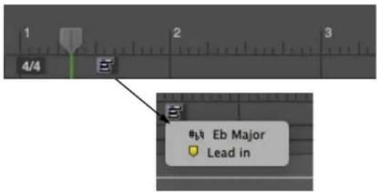
Figure 38-7: When items in the Marker Strip occur very close to one another (or even on the same exact tick), the Median Strip displays a single icon as shown here. Click the icon to see a menu of the events; you can select them by choosing them from the menu.
Markers
In the Marker Strip, a marker appears as a marker icon, followed by the marker's name. The marker icon indicates the marker's exact location. If the marker is locked, a lock icon will appear between the pointer and the marker name.

Figure 38-8: A locked marker.
Showing marker grid lines
The Show marker grid lines Edit Window preference (see “Edit Window guides” on page 91) toggles the appearance of a yellow line that extends downwards from each marker through the note grid, median strip and continuous data grid. This line can be used to align notes to the marker location.
Snap to Markers
To make items snap to marker locations (regardless of whether marker grid lines are currently displayed), enable the Snap to Marker option in the Snap Information window or Information Bar. For more details, see “Snap Information” on page 355.
Making a time-range selection with markers
Click the marker to make a time range selection that extends to the next marker.
Editing markers
To move, delete or otherwise edit the marker, use the Conductor track or the Markers window. See chapter 64, “Markers” (page 771) for more information about editing markers.
Markers in the Conductor Track Graphic Editor In the Conductor track, markers are displayed in the Median Strip. See “Editing in the Conductor Track” on page 434 for more information.
Meter and key changes
Meter and key changes appear in the Marker Strip in much the same way as they do in the Event List. (Tempo changes are not displayed in the Marker Strip.) Similarly, they can only be edited in the Conductor track. See “Editing in the Conductor Track” on page 434.
The Memory Cycle Strip (Figure 38-1 on page 372) displays the Memory Cycle loop as a colored bar. Drag in the strip to enable Memory Cycle and set the start and end times. Drag the endpoints of the bar to change them, or drag the bar to move it. Click the bar to toggle Memory Cycle on or off. Also see “The Memory Cycle button” on page 207 and “Link Playback to Memory” on page 209.
The Auto Record strip (Figure 38-1 on page 372) displays the Auto Record punch-in/out region as a colored bar, which works in the same fashion as described for the Memory Cycle bar above. Also see “Auto-Record” on page 210.
ZOOM BUTTONS
The Sequence Editor lets you zoom all tracks both horizontally and vertically. Zoom in using the 'plus' button to get more detail. Zoom out with the 'minus' to get more of an overview. If you press continuously, the window zooms continuously. Shortcut: Option/Alt-click to zoom to the
maximum or minimum setting. When zooming vertically, tracks proportionally maintain their relative vertical sizes.
Figure 38-9: The Sequence Editor Zoom buttons.
ZOOMING TECHNIQUES
In addition to the zoom buttons shown above, Digital Performer provides many other ways to zoom in and out, including many useful zooming shortcuts. In particular, you can very quickly and conveniently zoom in and out with the scroll wheel on your mouse or the track pad on your laptop. For details, see “Zooming with the wiper” on page 228 and “Zooming” on page 331.
Zoom shortcuts
The View menu > Zoom sub-menu provides many useful options for magnifying or reducing the data displayed in the Sequence Editor. See “Zoom menu shortcuts” on page 332.
AUDIO TRACK SETTINGS
The panel to the left of each track shows all of the settings for the track. Audio track settings are as follows:
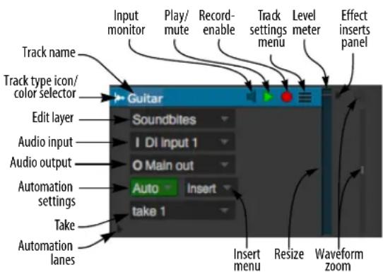
Figure 38-10: Audio track settings. The display of these controls changes depending on the vertical size of the track.
For the following universal track settings, see "The Track List" on page 175:
■ Play/mute button
■ Record-enable button
■ Automation settings
Take
■ Lock
■ Solo Exempt
■ Comment
For the following audio-specific track settings, see "Audio track settings" on page 148:
■ Audio input
■ Audio output
■ Input monitor
■ Stretch
■ Pitch and Stretch Cache
■ Enabled
The remaining track settings, which are unique to the Sequence Editor, are discussed below.
Track names
Track names operate identically to their counterparts in the Tracks window and offer the following features:
- Click, Command/Ctrl-click, or Shift-click a track name to select the track for deleting, duplicating and other track management tasks. See “Track management” on page 377.
■ Option/Alt-click the track name to rename it. - Command-double-click a track name to open the Mixing Board with that track's channel showing.
■ Control/Win-click on a track name to access a menu of options for managing tracks.
■ Track names highlight if there is a selection in the track.
Track type icon/color selector
The track type icon serves two roles: 1) it tells you what type of track you are looking at with an icon (identified in "The track type icon" on page 127), and 2) if you click on the icon, you can choose the track color.
Locked tracks display a line under their name
If a track is locked, its name is underlined.
The Edit Layer
In the Sequence Editor, tracks can display multiple types of data at the same time (soundbites, volume mix automation, pan automation, etc.), superimposed on top of one another. Each type of data resides in its own edit layer, which you can make active (bring to the front) while other layers remain dimmed but visible in the background.
The Edit Layer menu (Figure 38-10 on page 380) lets you choose what type of data you would like to "bring to the front" as shown below in
Figure 38-11. In audio tracks, mix automation data (volume, pan, etc.) and loops are displayed directly on top of the soundbites, which are dimmed in the background. When soundbites are made active, they cover automation data. MIDI continuous data and audio mix automation lines remain dimmed and visible in the background when notes or soundbites are chosen as the edit layer.
When a data type is made active, it can be inserted and edited independently of other data types.

Figure 38-11: Choosing the edit layer.
Choosing the edit layer for all tracks at once
Hold down the Option/Alt key when choosing what to display to change all tracks at once. You can do so from any track.
Shortcuts for changing the edit layer
Here are a few shortcuts for choosing the edit layer:
■ To activate soundbites for editing, click the title of any soundbite.
■ To activate any type of automation data, click on any control point.
■ To activate any event flag (explained later in this chapter), click it.
See Figure 71-16 on page 862 for an illustration of these techniques.
The Edit menu> Continuous Data sub-menu provides numerous commands for working with the edit layer. The Commands window provides keyboard shortcuts.
Hiding background layers
You can temporarily hide all MIDI controller layers and audio mix automation layers that are currently background layers (not the edit layer) with the Show Active Layer Only command in the View menu (see “Show Only” on page 327).
Using lanes instead of edit layers
As an alternative to using edit layers, you can show separate lanes for each type of automation data. See “Displaying automation lanes” on page 403.
Using edit layers
For further information about using each edit layer, see below.
Edit layer For more information
| Show Lanes “Displaying automation lanes” on page 403 | |
| Soundbites “Audio editing basics” on page 388 | |
| Volume Pan | “Working with breakpoint mix automation” on page 403 |
| Pitch chapter 81, “Transposing Audio” (page 935) | |
| Stretch “Stretching audio beats in the Sequence Editor” on page 692 | |
Bite Volume "Soundbite volume automation" on page 407
Level meter
Each audio and MIDI track displays a mono or stereo level meter (with red clip indicator). These level meters function identically to the level meters in the Mixing Board. For details, see “Level meters” on page 839.
Track settings menu
The track settings menu (Figure 38-10 on page 380) provides all of the track's settings in menu form, as shown in Figure 38-13. Since tracks can be resized vertically (see "Resizing tracks" on page 386), many of their panel settings get covered up when their vertical size is reduced. However, the Track Settings menu remains visible, even at a track's smallest vertical height, so that you always have access to all of the track's settings.

Figure 38-13: Even when a track is reduced vertically to its smallest size, the Track Settings menu gives you access to all track settings.
For audio tracks, most of the items in the Track Settings menu are explained in “Audio track settings” on page 148. However, there are a few menu settings that are specifically related to the Sequence Editor:
Setting For further information
| View mode “View Mode” on page 383 |
| Set Pitch Mode “Setting the pitch mode” on page 940 |
Pitch "Temporarily disabling pitch modifications" on page 944
View Mode
The View Mode sub-menu (Figure 38-13) Lets you display an audio track in the Sequence Editor in three ways: as a waveform, as a spectrogram or both. As demonstrated in Figure 38-12, the Drums track shows the spectrogram for a stereo track using the default track color (on a white background). The Rhythm Guitar track shows the spectrogram for a mono track using the Jet color scheme. Several color schemes are provided at the bottom of the View Mode menu. The Solo track shows both the waveform and spectrogram side by side.
The spectrogram display
The spectrogram display shows frequency content (along the vertical axis) against the Sequence Editor time line (horizontal axis). Bright spots indicate harmonic content in the audio frequency spectrum. This gives you visual insight into the frequency content of your audio, which can help you do things like balance the frequency content of your tracks using visual feedback. You can also use DP's extensive plug-in processing to manage and manipulate the frequency content of your audio tracks, and the spectrogram display allows you to view the results visually.

Figure 38-12:
Waveform/note grid vertical zoom
The vertical zoom menu (Figure 38-14) vertically shrinks or expands the waveform display in an audio track and the note grid in a MIDI track. In audio tracks, it has no effect on the actual amplitude of the audio in the track; it is for display purposes only. Option-drag to vertically zoom all audio tracks or all MIDI tracks.

Figure 38-14: Waveform/note grid vertical zoom.
Insert menu
The insert menu in each track lets you choose any type of data to insert into the track (except soundbites). In audio tracks, you can insert volume, pan, send levels, track mutes and plug-in parameter automation for any plug-ins currently assigned to the track. For complete details, see "Inserting and editing automation" on page 860. In MIDI tracks, you can insert any type of MIDI data.

Figure 38-15: The Insert menu.
MIDI TRACK SETTINGS
MIDI tracks have the following settings:

Figure 38-16: MIDI track settings. The display of these controls changes depending on the vertical size of the track.
Several of these settings are the same as they are for audio tracks:
■ "Track names" on page 380
■ "Track type icon/color selector" on page 381
■ "The Edit Layer" on page 381
■ "Track settings menu" on page 382
■ "Level meter" on page 382
■ "Insert menu" on page 384
For the following universal track settings, see "The Track List" on page 175:
■ Play/mute button
■ Record-enable button
■ Automation settings
Take
■ Lock
■ Solo Exempt
■ Comment
For the following MIDI-specific track settings, see "MIDI track settings" on page 140:
■ Default patch
■ MIDI input
■ MIDI output
The remaining MIDI track settings, which are unique to the Sequence Editor, are discussed below.
MIDI track settings menu
The track settings menu provides all of the track's settings in menu form. Since tracks can be resized vertically (see "Resizing tracks" on page 386), their panel settings get covered up when their vertical size is reduced. However, the Track Settings menu remains visible, even at a track's smallest vertical height, so that you always have access to the track's settings.

Figure 38-17: All of a MIDI track's settings are available in its track settings menu, including MIDI device output assignment and continuous data display mode.
Note grid vertical zoom
The note grid vertical zoom menu lets you grow or shrink the number of octaves visible in the track's note grid, as demonstrated in Figure 38-14. You can also control whether note names are displayed on every key or just every octave. See "Pitch Ruler Settings" on page 92.
Note grid scroll bar
The note grid scroll bar lets you scroll the note grid up and down, just like the MIDI Editor note grid. See “The Pitch Ruler” on page 418 and also see “Viewing notes that are out of view” on page 418.
WORKING WITH MIDI TRACKS
Working with MIDI tracks in the Sequence Editor is almost identical to working with them in the MIDI Editor, with the following several differences:
■ In the Sequence Editor, MIDI tracks allow you to view and edit Clips. See “Working with Clips” on page 400.
■ Continuous data is superimposed on top of the note grid, instead of being displayed in a separate area below it. Functionally, however, it works the same way as the MIDI Editor: inserting and editing continuous data when it is the edit layer is the same as working with it in the Continuous Data Grid.
■ Median Strip events are displayed as event flags across the bottom of the track. For further details, see “Working with event flags” on page 407.
- When notes have been chosen as the active layer, continuous data remains visible as thin lines drawn in the track's color behind the notes (rather than on a separate grid as in the MIDI Editor)
■ Because of its multi-track design, the Sequence Editor allows you to easily drag MIDI data from one track to another by dragging it vertically.
Except for these differences, everything about working with the note grid and continuous data (in Lines Mode) is the same as described in chapter 39, “MIDI Editor” (page 411).
RESIZING TRACKS
Both MIDI and audio tracks can be resized vertically. Position the mouse over the bottom edge of the track settings panel until you see the hand cursor. Then drag up or down as desired.

Figure 38-18: Resizing tracks vertically.
Shortcuts for vertical track resizing
Use the following shortcuts to resize tracks:
| To do this: | Hold down this key while dragging: |
| To make all tracks the same height Option/Alt key | |
| To enlarge one track and make all other tracks scale their height to fit in the window | Control/Win key |
| To zoom back to the previous state after either of the above operations | Press command-| (left bracket), or choose Zoom Back from the Zoom sub-menu in the Sequence Editor mini-menu. |
| To make tracks snap to fixed sizes vertically | Command/Ctrl key |
These modifier key shortcuts can also be used when vertically resizing from track setting menus as shown below:

Figure 38-19: Resizing tracks from the track settings menu.
Resizing the track info panel
The Track Info Panel (Figure 38-10 on page 380) can be resized horizontally by dragging the handle on its right-hand edge. The menu items for each track automatically rearrange themselves in the panel as its width changes. By dragging it further to the right, you have more direct access to the menus when viewing many tracks at once with small vertical track settings, as demonstrated in Figure 38-20:

Figure 38-20: Track Info panel can be resized horizontally.
EFFECT INSERTS PANEL
Click the Effect Inserts panel button (Figure 38-10 on page 380) to show or hide the effect insert panel for each track as shown below. These are the same effects inserts for the track in the Mixing Board. See "Inserts" on page 827.
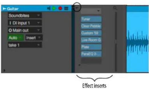
Figure 38-21: Effect inserts panel.
AUDIO EDITING BASICS
This section explains several important concepts to keep in mind when you work with audio tracks in the Sequence Editor.
Working with waveforms
The Sequence Editor displays soundbites — and the audio data within them — as a waveform in a standard time-versus-amplitude display as shown in Figure 38-22. The waveform shown inside soundbites is a representation of the sound in graphical form. Time is expressed on the horizontal axis. Amplitude (loudness) is expressed on the vertical axis, and the waveform oscillates up and down over a center axis which represents zero, or no sound at all. The louder the sound is at a certain point, the greater the deviation is from zero. Silence is represented by a straight line. the point at which the waveform crosses zero is called a zero-crossing.
A soundbite is represented as a “block” of waveform data with adjustable boundaries. The waveform inside it represents the actual audio data in the audio file on disk. This graphic display allows you to make edit decisions based on what you see, as well as what you hear.
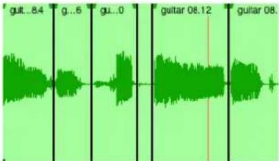
Figure 38-23: A soundbite is represented as a block of audio with a waveform inside.
Stereo versus mono waveforms
In stereo tracks, paired left/right soundbites appear in the Sequence Editor as two smaller waveforms joined together as shown in Figure 38-24. A stereo soundbite shows both channels connected together as one unit, so that they can always be edited simultaneously, with sample-accurate phase lock between the channels.
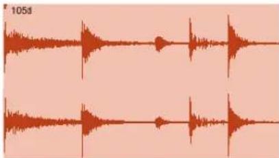
Figure 38-24: A stereo soundbite is represented as two audio channels joined together, which always remain phase-locked.
Surround waveforms
In surround tracks, grouped surround audio files appear in the Sequence Editor as a surround soundbite, which consists of multiple channels

line
| Time | Amplitude | |------|---------| | 0 | 0 | | 50 | +100% | | 100 | 0 | | 150 | -100% | | 200 | 0 | | 250 | +100% | | 300 | 0 | | 350 | -100% | | 400 | 0 | | 450 | +100% | | 500 | 0 | | 550 | -100% | | 600 | 0 | | 650 | +100% | | 700 | 0 | | 750 | -100% | | 800 | 0 | | 850 | +100% | | 900 | 0 | | 950 | -100% | | 1000 | 0 |Figure 38-22: A simple audio waveform displayed on a time versus amplitude scale.
connected together as one unit, as shown below in Figure 38-25. In the Sequence Editor, all channels of a surround soundbite are always edited simultaneously, with sample-accurate phase lock between the channels. You can edit surround channels separately in the Waveform Editor.
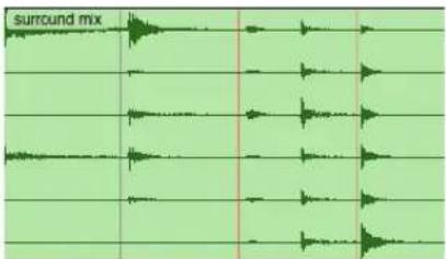
Figure 38-25: A 5.1 surround soundbite.
Soundbites are clones
An important thing to realize about soundbites in the Sequence Editor is that they are “clones” of their original soundbite in the Soundbites window as shown in Figure 34-7 on page 335. For further explanation, see “Soundbites in a track are ‘clones’ of the original” on page 335.
Graphic editing is nondestructive
All of the editing procedures described in this chapter are non-destructive. For an explanation of non-destructive editing, see “Non-destructive, destructive and constructive audio editing” on page 336.
Soundbites that cannot play
Soundbites that cannot be played (because they don't match the project's global sample rate, for example) are displayed in the Sequence Editor with a red outline and a grayed waveform, in addition to a red 'X' in their icon in the Soundbite list, to alert you to the fact that they cannot currently play back.
Viewing Sequence Editor soundbites in the Soundbites window
If you are looking at a soundbite in the Sequence Editor, and you would like to find it in the Soundbite list, use the Command in the
Commands window called Select this soundbite in the Soundbite list. Use the search feature in the Commands window to find the command and then assign it to any desired keyboard shortcut. There is a similar command called Display this soundbite in Waveform Editor. See “Searching for commands” on page 105.
Reveal In Finder/Show in Explorer command
The Reveal In Finder/Show in Explorer command shows you the location on your computer desktop of the parent audio file for the currently selected soundbite or clippings. By default, the keyboard shortcut for this command is Option/Alt-R.
INSERTING SOUNDDBITES
The following sections explain several different ways to insert soundbites into the Sequence Editor. The soundbite must be present in the Soundbites window list before doing so. If it isn't, you must import it beforehand. See “Importing and exporting audio” on page 47.
Dragging and dropping audio into the Sequence Editor
You can also place audio in the Sequence Editor by dragging soundbites from the Soundbites window, a Clipping window or the computer desktop. In the Soundbites window, just grab the move handle of the soundbite and drop it on top of the open Sequence Editor. The soundbite is placed at the exact location displayed in the cursor information box at the moment you drop it. Control/Win-drag the soundbite to make it “snap” to the end of the previous one (or the beginning of the track if it is empty). In the macOS Finder or Windows Explorer, just drag the audio file icon from the desktop or any window into the Sequence Editor. The soundbite’s number of channels (mono, stereo, 5.1 surround, etc.) must match the number of channels for the track you wish to insert it into.

Figure 38-26: Dragging and dropping Soundbites into the Sequence Editor from the Soundbites window: grab the move handle and drop it on top of the Sequence Editor. Use the Cursor Information for precise placement. Control/Win-drag the soundbite to make it "snap" to the end of the previous one. You can also drag and drop audio into the Sequence Editor from the computer desktop.
Using the Insert Audio command
To insert a soundbite in the Sequence Editor with the Insert Audio command:
1 Press Shift-F1.
This is the default key binding for the Insert Audio command, but this may be reassigned in the Commands window.
2 Select the desired soundbite from the list that appears. The soundbite's number of channels (mono or stereo) must match the number of channels for the track you wish to insert it into.

Figure 38-27: Click the soundbite name and then click OK, or—as a shortcut—simply double-click the soundbite. You can also select the desired soundbite by typing the first letter of its name. When the list disappears, the cursor turns into a cross-hair.
Click the cross-hair cursor in the Sequence Editor at the location where you want to place the soundbite, using the cursor information (see page 358) to help determine the location.
Building a playlist
You can quickly build a playlist in the Sequence Editor by Control/Win-dragging soundbites into it from the Soundbites window. Holding down the Control/Win key when you first grab the soundbite causes it to "snap" to the end of the previous soundbite when you drop it.
Changing a soundbite name
To change a soundbite name in the Sequence Editor, Option/Alt-click its name.
Replacing a soundbite with another
To replace a soundbite with a another one from the soundbites window, click it once to select it and click its name in the Event Information window as shown in Figure 38-1 on page 372.
MOVING SOUNDBITES
Soundbites can be moved earlier or later in time by simply dragging them left or right, respectively. If the Edit Resolution check box is off, they move freely at the highest resolution allowed by the current zoom level. An information tab appears while dragging (Figure 38-28) to provide metrics regarding the drag operation (new position, offset, start time, end time, destination track, etc.)

Figure 38-28: Dragging a soundbite.
Moving soundbites vertically from one track to another
You can freely drag soundbites from one track to another simply by dragging them vertically — as long as the tracks involved are currently being displayed, of course.
Constraining dragging operations
You can vertically or horizontally constrain dragging operations in the Sequence Editor by holding down the Shift key while dragging. This applies to soundbites, automation data, MIDI data and other events.
Moving multiple soundbites at the same time
You can move several soundbites together by selecting them and dragging them together as a unit. Shift-click to select multiple soundbites. Also see “Selection techniques” on page 396.
Snapping to the edit grid
When the Snap to Grid check box is checked in the Snap Information window, soundbites "snap" to the Edit Resolution grid when you drag them. Snapping can be absolute or relative. See "Snap to Grid" on page 355 and the edit grid controls in Figure 38-1 on page 372.
Canceling while dragging
If you are in the middle of dragging, and you change your mind, you can press the escape key while dragging to immediately cancel the operation and restore the data to its original position, unchanged.
Nudging soundbites with the arrow keys
Select one or more soundbites in the Sequence Editor and type the left or right arrow keys on your computer keyboard to nudge the data forward or backward in time. Use the Nudge Amount in the Snap Information window (or Information Bar) to control the resolution. See "Nudge" on page 358.
"Throwing" soundbites to the next or previous soundbite
There is a shortcut for making a soundbite “snap” to the next or previous soundbite in the window: click the soundbite first to select it, and then Control/Win-drag the soundbite in the direction you want it to snap. For example, if you want a soundbite to be placed end-to-end with the next soundbite to the right as shown below, select it and then control-drag it to the right. You only have to drag a short distance—enough to determine the direction.

Figure 38-29: Control/Win-dragging a selected soundbite a short distance in either direction causes the soundbite to "snap" to the next or previous soundbite.
Option/Alt-dragging to make a copy
To quickly make a copy of a soundbite while dragging, Option/Alt-drag it. The new soundbite is an exact clone of the original; in other words, they both refer to the same original soundbite listed in the Soundbites window. For example, if you rename either copy, they will both change to the new name.
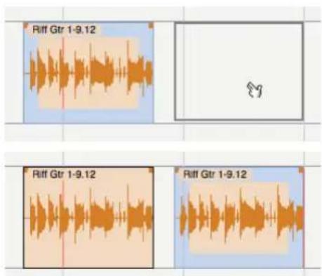
Figure 38-30: Option/Alt-dragging to make a copy of a soundbite.
Option/Alt-Control/Win-dragging to copy soundbites & place them end to end
By holding down both the Option/Alt key and the Control/Win key when dragging soundbites, you can copy and place soundbites end-to-end at the same time. This is a great shortcut for building playlists made up of many repeating soundbites, as shown in the example below.

Figure 38-31: Option/Alt-Control/Win-drag soundbites to quickly place them end to end.
Creating a stutter effect
You can easily make a stutter effect by Option/Alt-dragging a soundbite several times and overlapping the copies. For rhythmic precision, it is easiest to do so with edit resolution turned on and set to a fairly small increment, such as 16th notes.
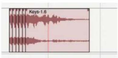
Figure 38-32: This 16th-note stutter effect was created by Option/Alt-dragging copies of a soundbite with edit resolution turned on.
MUTING AND UNMUTING SOUNDDBITES
There are two ways to temporarily mute a soundbite:
■ Insert mute automation
■ Use the Mute tool
Inserting mute automation
To mute a soundbite using mute automation, select it and choose Mute Region from the Region menu. This inserts mute automation data at the beginning and end of the soundbite. To unmute, select it again and choose Clear Mute Automation from the Region menu.

Figure 38-33: When using the Insert Mute Automation command (Region menu), mute automation data is inserted in the track.
Using the Mute tool
To mute the soundbite with the Mute tool, click it with the Mute tool. To unmute, click it again with the Mute tool. The Mute attribute for a soundbite can also be toggled in the Event Info panel. See "Event Information" on page 359.

Figure 38-34: Muting a soundbite with the Mute tool.
BITE GAIN
When audio tracks are resized vertically, and expanded far enough, each soundbite displays its Bite Gain setting and fader in the bottom left corner as shown in Figure 38-35. Bite Gain non-destructively raises or attenuates the overall volume of the soundbite. The range is from -140 to +80 dB. This is the same setting as found in the Sound File Info panel (see “Sound File Information” on page 365). Click the fader icon to adjust the Bite Gain.
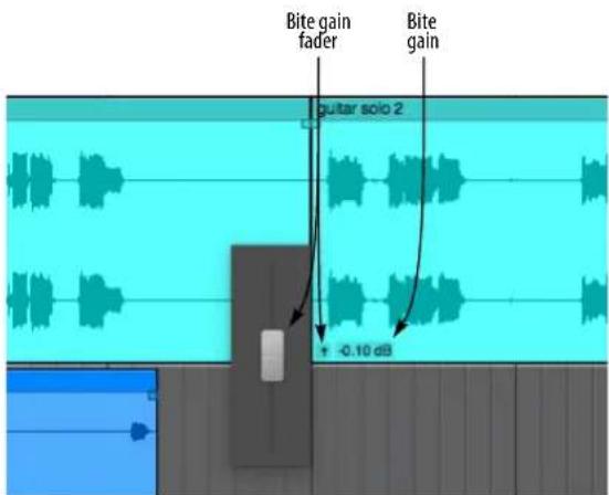
Figure 38-35: Bite Gain setting and fader.
OVERLAPPING AND LAYERING SOUNDBITES
Digital Performer allows two or more soundbites—or portions thereof—to occupy the same location in an audio track. Each soundbite is handled in a separate layer that can be manipulated independently of other soundbites. However, only the visible portion of each soundbite plays back. A simple, intuitive rule of thumb is: what you see is what you hear. In other words, when one soundbite covers up another, it also takes over playback in the track.
Use the Layering commands in the Edit menu (Move Forward/Backward and Move to Front/Back) to control how overlapping soundbites are layered as you edit them.
TRIMMING (EDGE EDITING) SOUNDBITES
As explained in Figure 8-6 on page 61 in the DP Getting Started Guide, a soundbite represents a portion of audio from its parent audio file stored on disk. For example, a soundbite can be as short as a fraction of a second or as long as many hours. A soundbite can represent a portion of the parent audio file, or it can represent the entire file.
The Pointer, Trim, Roll, Slip and Slide tools
The Pointer, Trim, Roll, Slip and Slide tools (shown below in Figure 38-36) can be used to edit the edges of a soundbite. The current edit resolution applies.
Pointer: The Pointer tool allows you to trim the left or right edge of a soundbite. The arrow cursor changes to the trim cursor (Figure 38-36) when you move it near the edge of a soundbite. When trimming, you “uncover” or “cover up” the audio in the audio file as illustrated in Figure 38-36. If the edge stops when you drag it, preventing you from going any further, then you have reached the end of the audio file.
Trim: The Trim tool allows you to click anywhere in a soundbite to move the right edge to the location where you clicked. Hold down the Option/Alt key to move the left edge to where you click.
Roll: The Roll tool allows you to edge edit the beginning of one soundbite and the end of another where they abut each other. They must be touching one another.
Slip: The Slip tool allows you to edge edit the start and end of a soundbite while the soundbite remains at the same position in the track. The soundbite's length does not change.
Slide: The Slide tool allows you to move a soundbite in the sequence while leaving the soundbite's audio at the same playback time. This is the same as trimming both ends by the same amount forwards or backwards.
Affecting all copies of a soundbite versus one copy
The Edge Edit Copy command in the Sequence Editor mini-menu allows you to choose whether you want to modify the original soundbite you are dragging or preserve the original by making a copy of it when you drag.
When Edge Edit Copy is unchecked, dragging a soundbite edge affects the original soundbite, as well as every other instance of it. For example, if you edge edit a soundbite called Drum Fill that has been placed many times throughout a percussion track, all copies of it in the track will change.
When Edge Edit Copy is checked, it causes a soundbite to be copied when you drag one of its edges, which preserves all original copies of the soundbite. The result is a new soundbite that is identical to the original except for the new boundary and a slightly different name. You probably won't even notice that a copy is being made. Instead, it will seem like you just moved the edge of the soundbite. The only noticeable change is a number appended to the soundbite (or, if it already has a number, it will increment by 1). The new soundbite is also added to the list in the Soundbites window.

Figure 38-36: Edge editing a soundbite by dragging its boundaries.
Original soundbite New soundbite
after Option/Alt-dragging its edge
Figure 38-37: Edge Edit Copy.
Option/Alt-dragging to override Edge Edit Copy
Option/Alt-dragging a soundbite edge temporarily overrides the current setting of the Edge Edit Copy command. This allows you to set it the way you prefer most of the time, and the Option/Alt-drag to temporarily override it when necessary. For example, if you may want to edit all instances of a soundbite most of the time, uncheck the Edge Edit Copy command so you can simply drag soundbite boundaries, and use the Option/Alt key to override this setting when needed.
Edge editing multiple soundbites
To trim (edge edit) multiple soundbites together at the same time, select them, and then trim either the left edge or right edge of any selected soundbite.

Figure 38-38: To trim multiple soundbites together in one operation, select them and drag an edge.
If you would like all edges to snap to the same location, hold down the Control/Win key while dragging an edge as shown below:
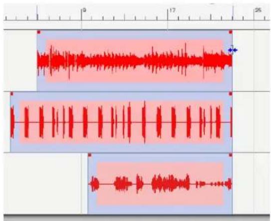
Figure 38-39: To make the edges of multiple soundbites snap to the same location, hold down the Control/Win key while trimming.
Edge editing when soundbites overlap
When soundbites overlap one another, you may not have direct access to the soundbite edge you wish to edit because it may be covered up by another soundbite, and you may not want to change how they overlap with the layering command in the Audio menu. In this situation, you can edit the hidden edge by Shift-clicking the opposite, visible edge. Doing so gives you control over the edge you didn't shift-click.

Figure 38-40: Edge editing when the edge you want to drag is covered by another soundbite.
Using the edit grid when edge editing
The edit grid does not affect edge editing. However, if you would like your edge edit to snap to the edit grid, hold down the Command/Ctrl key while clicking on the soundbite edge to move it.
Scrubbing while trimming soundbites
If Audible Mode is turned on (the button in the Control Panel with the speaker icon), audio scrubs as you drag the edge of a soundbite to trim it. This allows you to hear your trim edits as you make them. You can adjust the volume for scrubbing using the Audition volume preference. See "Audition volume" on page 95. Also see "Specifying audio output for auditioning" on page 338.
Using Slip, Slide and Roll on multiple soundbites
You can use the Slip, Slide and Roll tools (as described earlier on page 393) on multiple selected soundbites.
GRAPHIC TIME STRETCHING OF AUDIO
You can time-stretch audio graphically by grabbing the edge of a soundbite with the hand tool and dragging it to the desired length. To get the hand tool, position the cursor over the edge of the soundbite, just below the crossfade handle as shown in Figure 38-41. When time-stretching a soundbite that has a sync point, audio stretches or shrinks around the sync point, which remains anchored to its original location. For details, see "Time-stretching and sync points" on page 400.

Figure 38-41: To graphically time-stretch a soundbite, position the cursor over the edge of the soundbite just below the crossfade handle and grab it with the hand cursor.
APPLYING FADES AND CROSSFADES
You can apply fades and crossfades to the boundaries of soundbites using fade handles or time range selections. For complete details, see “Fades and Crossfades” on page 657.

TAKES
Takes are a way to store multiple versions of a track within a single track. You can add, delete, expand, absorb, and comp takes using the Takes menu and the Comp tool. For complete details, see chapter 51, "Takes and Comping" (page 665).
GRAPHIC EDITING TECHNIQUES
All of Digital Performer's powerful editing features are available in the Sequence Editor. Most editing can be done with the mouse using familiar actions like clicking, dragging, and Shift-dragging. Such actions can shift data, change note pitch and duration, reshape mix automation data curves, and more. For a summary of Digital Performer's basic graphic editing techniques, see “Graphic editing techniques” on page 334.
SELECTION TECHNIQUES
Digital Performer offers a variety of ways to select audio and MIDI data in the Sequence Editor. After audio is selected, you can apply one of Digital Performer's many powerful editing operations. For a complete discussion of selecting techniques in the Sequence Editor, see chapter 45, "Selecting" (page 547). The sections below discuss several selection operations that are unique to the Sequence Editor.
Selecting a time range in the time ruler over one or more tracks
To select any time range, regardless of the audio or MIDI data contained within that range, drag in the time ruler as shown below. A time ruler selection affects all visible tracks, as well as all data currently visible in the view filter. Be sure to hide tracks and data types you don't wish to include. Mix automation data in the time range will also become selected, unless they are hidden in the View Filter. Shift-click to extend or shorten the current selection. You can also turn on the edit grid when dragging.
Pasting into a time ruler selection
If there is data in the clipboard, you can use the Paste or Merge commands. Doing so pastes the clipboard contents into the same track (or tracks) it was copied or cut from starting at the beginning of the selected region.
Scrubbing audio inside a popped-up soundbite
To scrub audio inside a soundbite, use the Scrub tool (in the Tool Palette). You can also double-click the soundbite with the Arrow tool to pop-edit it and then Command/Ctrl-drag in either direction to scrub forwards or backwards as shown below. The scrub wiper indicates the current scrub location.

Figure 38-43: Command/Ctrl-drag to scrub audio within a pop-edited soundbite. In this example, the audio is being scrubbed forwards.
Controlling scrubbing speed
To speed up scrubbing — up to two times normal speed — move the “scrub wheel” cursor further away from the scrub wiper. To slow down, move

Figure 38-42: Selecting a time range using the time ruler.
the scrub wheel cursor closer to the scrub wiper. For a finer degree of control, zoom in the display horizontally.
Scrubbing while selecting
When dragging to make and adjust selections inside a soundbite, you can scrub the audio while selecting by holding down the Command/Ctrl and Shift keys together as shown below in Figure 38-44. This lets you hear what you are selecting as you drag. For example, if you have made a selection already, and you want to extend its edge and scrub at the same time, hold down both the Command/Ctrl and Shift keys while you drag.
natural_image
Audio waveform visualization with three distinct color-coded segments (blue, green, red) showing varying amplitude patterns across the timeline.Figure 38-44: Scrubbing while selecting.
Adjusting the volume for scrubbing
You can adjust the volume for scrubbing using the Audition volume preference. See “Audition volume” on page 95. Also see “Specifying audio output for auditioning” on page 338.
Using the Search command to select data
The search command offers powerful ways to select data. For details, see chapter 46, "Searching" (page 561).
Editing selected audio data
After you have selected audio data using one of the methods described in the previous sections, you can employ Digital Performer's numerous editing commands. For complete information, see chapter 47, "Edit Menu" (page 573), chapter 48, "Region Menu" (page 593) and chapter 49, "Audio Menu" (page 645).
SHOW TIMES
The Sequence Editor mini-menu has a command called Show Times, with several sub-menu options, that display the SMPTE time code start and end times of each soundbite. The time locations are displayed in the upper left-hand corner of each soundbite as shown below in Figure 38-45.
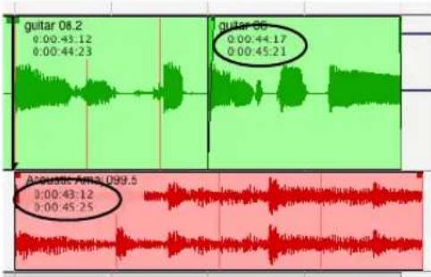
Figure 38-45: The Show Times menu lets you choose how to display the location of each soundbite.
Current Time
When you choose Current Time in the Show menu, all soundbites display their current location.

Figure 38-46: SMPTE start and end time.
Original Timestamp
When you choose Original Timestamp in the Show Times menu, soundbites display the time at which they were originally recorded (or created), regardless of where they currently reside. If a soundbite does not have an original timestamp (perhaps it was created in an earlier version of Digital Performer that didn't support timestamping), then no times will be shown.
If a soundbite has an original timestamp, you can move the soundbite to its original time with the Timestamps command in the Audio menu.
User Timestamp
When you choose User Timestamp in the Show menu, soundbites display their user timestamp, if they have one. If a soundbite does not have a user timestamp, then no times will be shown.
If a soundbite has a user timestamp, you can move the soundbite to its user timestamp location with the Timestamps command in the Audio menu.
For applying user timestamps to soundbites, see "Setting a user timestamp" on page 651.
SYNC POINTS
A sync point can be placed inside a soundbite as positional reference point for the soundbite instead of its beginning (left edge). For example, if you have a soundbite that consists of a hinge squeak followed by a door slam, followed by a hollow echo, you could put the sync point right at the door slam.
Sync points can also be very important for percussive hits that have a small bit of sound before the hit, such as a “ruff” snare hit. The example below in Figure 38-47 shows a cymbal crash with a small snare roll going into it. The Sync point has been placed at the cymbal crash, which is the highest point of rhythmic interest.

Figure 38-47: A soundbite sync point.
The sync point determines how the soundbite will be positioned when doing things like quantizing the soundbite or dragging it.
Creating a sync point
To create a sync point:
1 Double-click the soundbite in the Sequence Editor to pop-edit it.
2 Click at the desired location inside the pop-edited soundbite to place the flashing cursor. Use scrubbing, if necessary, to find the desired location in the audio.
3 After you've placed the flashing cursor as desired, choose Set Sync Point at Insertion Point from the Audio menu. The sync point triangle appears.
Setting a sync point at the first beat
Choose Audio menu > Sync Points > Set Sync Point at First Beat to place the soundbite's sync point to the first beat within the current time range selection. If there is no selection, it will be placed at the first beat in the soundbite. Placing the soundbite's sync point at the first beat allows you to quantize the placement of the soundbite on any downbeat relative to the sequence time ruler.
Importing sync points
If you export audio regions with sync points from Pro Tools, you can import them with their sync points into Digital Performer.
Resetting sync points
To reset the sync point for one or more soundbites, select them and choose Reset Sync Points from the Audio menu. Resetting the sync point places it at the beginning of the soundbite.
Moving a sync point
You can move a soundbite's sync point in the Waveform Editor and the Soundfile Information panel. For details, see "Sound File Information" on page 365 and "Sync points in the Waveform Editor" on page 538.
Time-stretching and sync points
The location of sync points are preserved when you time stretch soundbites by dragging in the Sequence Editor as demonstrated below in Figure 38-48.

natural_image
Abstract waveform visualization with two green peaks and directional arrows on a light green background (no text or symbols)
natural_image
Two parallel abstract line patterns on a light green background, no text or symbols presentFigure 38-48: When you time-stretch a soundbite that has a sync point, the sync point anchors the time stretch, which extends out from the sync point in both directions.
Sync points in the Waveform Editor
Sync points are also displayed in the Waveform Editor. For details, see “Sync points in the Waveform Editor” on page 538.
Sync points and setting the meter for soundbite
The sync point determines the location of the downbeat of measure 1 in the soundbite. To set the meter for the soundbite, use the Time Signature setting as explained in “Sound File Information” on page 365. Each soundbite in the audio file can have its own unique sync point and meter.
WORKING WITH CLIPS
In the Sequence Editor, clips are viewed and edited in a fashion similar to soundbites, as explained earlier in this chapter. The following sections cover details that are specific to clips.
Clip basics
A clip is a container for a single track's worth of data. Think of it as a small slice of a track that you can manipulate as a single object. (See "What is a clip?" on page 290.) Clips also have object properties, such as a start time, duration and looping (on or off). (See "Clip settings" on page 295.) Clips can be identified by their rounded corners.

Figure 38-49: Clips in the Sequence Editor.
The Clip edit layer
Each audio and MIDI track provides an edit layer for Clips (Figure 38-49 on page 400) where clips can be managed and edited. Audio and MIDI tracks also have edit layers for soundbites and MIDI notes, respectively, allowing you to work seamlessly with clips and other data in the same track. Figure 38-49 shows an example of MIDI notes side by side with a MIDI clip in the same track. The same goes for soundbites, which can coexist side by side with audio clips in an audio track.
Click a clip in an audio or MIDI track to quickly switch to the Clips layer. Similarly, click a soundbite or MIDI note to quickly switch to the soundbite or notes layer.
Creating a clip
Here are some ways to create clip in a track:
■ Use the Pack Into Clips command (see below)
■ Drag and drop a clip from the Clips window into a track
■ Record clips as you trigger them from the Clips window (see "Clip Record mode" on page 297)
Recording MIDI into track clips
When you record into a MIDI track, Digital Performer can pack the data into a clip for you. To do so, enable the Record MIDI in Tracks as Clips preference (Figure 24-3 on page 235).
Packing track data into clips
To make a clip out of existing data in a track:
1 Make a selection (either an object selection or time-range selection) in one or more tracks.
2 Choose Region menu > Pack Into Clips.

Figure 38-50: Packing data into a clip.
If you make a multi-track selection, a separate clip is created in each track, since clips are a single-track objects by nature. (See “Clips versus clippings” on page 290.)
Unpacking clips
When unpacking data from a clip, the data remains behind, at its original location in the track, and the clip is removed:
1 Select one or more clips.
2 Choose Region menu > Unpack Clips.
Clip layering
Clips can overlap one another, just like soundbites. The front-most clip is what you hear. Use the layering commands (Edit menu) to manage layering. See “Overlapping and layering soundbites” on page 393. However, since clips can contain multiple types of data (unlike soundbites), layering them has further subtleties.
When the counter reaches a clip event during playback, that clip becomes the sole source of musical events for all the event types it contains. If there are any of the same event types in the track itself or in other clips layered behind the front-most clip, they are suppressed for the duration of that clip event. Types not contained in the front-most clip event are not suppressed by that clip, and will come from whichever source is closest to the
front, either another clip event or the track itself. Track data not contained in clips is always considered to be in the back-most layer.
The same concept applies when launching clips in the Clips Window, except only one clip can play per track at any given time, so there are only two possible layers to consider: the track layer and the clip layer. For clip events that are stored directly in tracks (and can be viewed in the Tracks Overview and Sequence Editor) there are as many layers as there are clip events in the track (just like soundbites).
As an example, automation in the track plays while looping a clip that contains only soundbites. However, you also have the flexibility to explicitly override parts of the mix automation, if desired. For example, you might create a one-bar clip that automates the Multimode Filter's center frequency parameter. Since this clip only contains automation data for a single plug-in parameter, it will not suppress soundbites in the underlying track data. It can then be launched and looped in the Clips window at will, repeatedly applying the filter sweep to whatever soundbites are playing back in the track.
Edge-editing a clip
When you edge-edit a clip, you are changing its start time or end time ("Clip settings" on page 295). To edge edit, position the cursor over the left or right edge of the clip and drag it. If the clip's loop setting is enabled, position the cursor over the bottom half of edge, as shown in Figure 38-51, to get the edge-edit cursor. The top half produces the loop cursor.

Figure 38-51: Edge-editing a clip.
Looping a clip
To loop a clip, double-click it to open the Clip Editor, and then enable its Loop setting in the settings panel. Once you've done so, position the cursor over the top half of the left or right edge of the clip (as shown in Figure 38-52) and drag it. In this example, looping has been extended both before and after the original clip. Each full iteration of the loop is indicated by boundary markers, as shown.

Figure 38-52: Looping a clip.
If you open a DP project file created in a version of Digital Performer earlier than 10.1, and the project contains loops, the loops will be converted into looped clips. Conversely, if you save to an earlier version of DP without clips, looped clips are converted to loops.
Muting/unmuting clips
To mute or unmute a clip, click it with the Mute tool (Figure 38-1 on page 372).
Other clip editing techniques
Clips can be edited with many of the same techniques as soundbites. See:
Moving soundbites....390
Muting and unmuting soundbites ....392
Overlapping and layering soundbites....393
The Pointer, Trim, Roll, Slip and Slide tools .....393
Edge editing multiple soundbites....395
Edge editing when soundbites overlap .....395
Using the edit grid when edge editing .....395
Opening the Clip Editor
To open the Clip Editor for a clip (as shown in Figure 38-49 on page 400), double-click the clip. When a clip is being displayed in the Clip Editor, it is highlighted in its track (as shown in Figure 38-49), so that you can clearly see which clip you are editing.
WORKING WITH BREAKPOINT MIX AUTOMATION
The Sequence Editor lets you display, insert, and edit volume, pan, plug-in parameters, send levels, track mutes and other mix automation data in the form of breakpoints (dots) on a continuous line. In audio tracks, mix automation data is stored in the form of sample-accurate control points that generate sample-accurate ramps during playback. In MIDI tracks, mix automation data is stored in the form of MIDI continuous controller data. For seamless, side-by-side operation of MIDI and audio tracks, the Sequence Editor displays both forms of automation with the same style of lines and points. The following sections discuss the specific techniques of working with breakpoint-style automation lines and points. Unless otherwise noted, the techniques are the same for both MIDI and audio tracks.
For complete details about working with MIDI continuous data, see “Editing continuous data in Lines mode” on page 429.
For complete details about working with audio mix automation, see “Inserting and editing automation” on page 860.
For complete details about working with pitch automation, see "Pitch automation" on page 936.

Figure 38-53: In the Sequence Editor, MIDI tracks and audio tracks display mix automation data with break-point automation curves.
Choosing the active data layer
To view, insert or edit mix automation data in a track, you must first make it the active layer as explained in “The Edit Layer” on page 381. Alternately, you can choose to show a separate automation lane as described below.
Displaying automation lanes
To display automation data in a separate lane below its parent track, choose Show Lanes from the Edit Layer menu (Figure 38-13 on page 382), or click the expansion triangle at the bottom of the track settings pane. Click the plus (+) and minus (-) buttons, as shown below in Figure 38-54, to add and remove additional lanes. Use the lane menu to choose the data type for the lane. To hide all lanes for a track, choose Hide Lanes from its Edit Layer menu.
The Edit menu> Continuous Data sub-menu provides numerous commands for working with automation lanes. The Commands window provides keyboard shortcuts.
The View menu provides shortcuts for showing and hiding automation lanes. See “Show/ Hide Lanes” on page 327.

Figure 38-54: Automation lanes.
Zooming for a better resolution
When inserting controllers, it helps to get a zoom level that best suits what you are doing. For example, if you are making fine adjustments to the track level, use a large vertical zoom level for better resolution. If you need to check out the overall level throughout a track, zoom out.
Inserting mix automation data
To insert mix automation data in the Sequence Editor:
1 Choose the data type you wish to insert from the active layer menu (Figure 38-10 on page 380) and then click the Pencil tool in the Tool palette (Studio menu).
2 If the desired data type does not yet have a layer, choose the desired automation data type from the track's insert menu. This creates a layer and turns the cursor into the Pencil tool.

Figure 38-55: Creating a new automation data layer for insertion.
3 Choose the desired shape of the curve you wish to insert from the Pencil/Reshape Curve menu in the Tool palette (shown below in Figure 38-56). If you wish to insert just a single point, the curve doesn't matter.
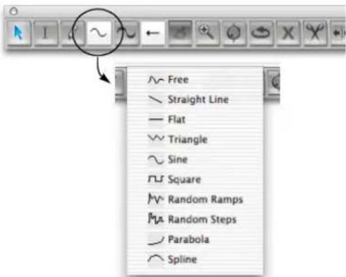
Figure 38-56: Choosing a shape for inserting a continuous data curve.
4 If you would like the curve shape you have selected to snap to beats or a similar metric grid, set the Edit Resolution and turn on the Edit Grid (see "Snap to Grid" on page 355).
Doing so constrains periodic waveshapes to the resolution of the edit grid. For example, if the Edit Grid is set to a quarter note, and you insert a sine wave, the sine wave will cycle once each quarter note.
Hold down the Command/Ctrl key to override grid snapping.
5 Insert data as follows:
To do this: Do this:
To insert a single event Click in the track with the Pencil.
To insert a stream of eventsDrag the Pencil. A stream of data is inserted according to the curve shape that you chose in the Tool palette. You can conform to a beat grid with Edit Resolution as explained in "Constraining a periodic waveform to beats" below, and you can use the waveform modifier keys described in "Using modifier keys to control period, phase, and other waveform parameters" on page 405.

Figure 38-57: Inserting a periodic waveform. In this example, a sine wave curve is being inserted.
Constraining a periodic waveform to beats
To insert a continuous data periodic waveform that conforms to a rhythmic grid (quarter notes, eighth notes, etc.), set the edit grid to the duration that equals one complete period of the waveform. This forces the waveform to conform to the grid duration you specify.
Using modifier keys to control period, phase, and other waveform parameters
When inserting (or reshaping) continuous data using a waveform shape as shown in Figure 38-57, you can hold down modifier keys while dragging to change waveform parameters as follows:
To control this: Hold down this key:
| Toggles grid snapping (on/off) Command/Ctrl key | |
| Phase Option/Alt key | |
| Duty cycle• Triangle wave skew• square wave pulse width• sine wave pulse width | Control/Win key |
| • Periodic frequency• Random curve density | Shift key |
To re-use the last settings for sineEscape key triangle, square, random steps or random ramps
Using the spline curve
The spline curve (Figure 38-56) provides three handles that can be adjusted for the desired shape during insertion. Just place the handles as demonstrated below in Figure 38-58 and then click anywhere off of the spline to complete the insertion.

line
| Signal Type | Value | |-------------|-------| | ASSOCIATED | 1980 | | ACTUAL | 1980 | | ACTUAL | 1980 |Figure 38-58: Inserting a mix automation curve with the spline tool.
Reshaping an existing curve
Use the same procedure as in the previous section to reshape an existing line or curve. Just drag over the existing data with the Reshape tool.
Selecting mix automation data control points
To select mix automation data:
1 Click the Pointer tool in the Tool palette (Studio menu).
2 Make a selection as follows:
To do this: Do this:
| To select a single event Click it with the finger cursor. | |
| To select several events Drag over the events in the grid with the lasso cursor. | |
| To select a continuous data curve | Drag over the curve with the lasso cursor. |
| To select all events of a data type | Double-click a control point of that type. |
| 'To add to the current selection | Hold down the Shift key while using any of the selection techniques above. |
| 'To deselect events Hold down the Shift key while using any of the above techniques on selected data. | |
| To deselect all data | Choose Deselect All from the Edit menu or press its keyboard shortcut. Or click once in any empty area in the Sequence Editor. |
Dragging control points
You can drag any control point on a line anywhere within the track strip. Notice that you can even drag it past events on either side of it as shown below. When you do, you delete the events that you drag over. This is a convenient shortcut for removing a curve.
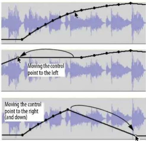
Figure 38-59: Dragging control points.
Selecting multiple data types at one time
To select several data types at one time:
1 Click the Pointer tool in the Tool palette (Studio menu).
2 Hold down the Option/Alt and Control/Win keys to get the cross-hair cursor and then drag over the desired time range in the track. Time range selections select all data within selected area, including audio and other types of automation data. (Lasso selection with the Pointer tool by itself only selects the active data type.)
In audio tracks, another way to make time range selections is to switch the active layer to Soundbites first, and then simply drag horizontally with the cross-hair cursor.
Selecting control points with soundbites (or MIDI notes)
Use the procedure described in the previous section.
Removing control points
To remove a single control point, click it to select it and the press the delete key. To remove a curve, drag over it horizontally in the track to select all of the points and then press the delete key.
Cutting, copying, and pasting control points
To cut, copy and paste audio mix automation or MIDI controller data in the Sequence Editor, select it first (as described earlier in “Selecting mix automation data control points” on page 406), and then cut, copy and paste them as usual. When pasting, you might find it useful to insert a control point at the location you wish to paste. Be sure it is selected before you paste. If you wish to preserve soundbites at the location where you are pasting, use Merge instead of Paste.
Disabling automation temporarily
To temporarily disable the automation data in an audio track, turn off automation playback as explained in “Global automation enable/disable” on page 853.
SOUNDBITE VOLUME AUTOMATION
Digital Performer provides an additional level of flexibility with regard to volume automation: soundbite volume automation, also referred to as bite volume. This is a non-destructive volume automation curve that you can apply directly to a soundbite. This volume curve then stays with the soundbite, in effect becoming part of the soundbite.
Accessing bite volume automation
Bite volume automation works similarly to the pitch automation layer described in “Pitch automation” on page 936. In the Sequence Editor track layer menu (Figure 38-11 on page 381), there is a menu item called Bite volume. Similarly, there is a Bite Volume edit layer in the Waveform Editor, as shown in Figure 44-1 on page 526. When you choose the soundbite volume automation layer in either of these two windows, you have access to soundbite volume automation data with each soundbite.
Working with soundbite volume automation
By default, the bite volume automation data in each soundbite is set to zero dB. The range is the same as track volume: -× to +6.02dB. In all other respects, bite volume data can be viewed, inserted, edited and otherwise handled in the same manner as track volume automation. The only difference is that bite volume automation always stays with the soundbite. You can also use the dedicated bite volume commands in the Audio menu. See “Bite volume and gain” on page 650. Bite volume is supported by the Change Continuous Data command (Region menu).
WORKING WITH EVENT FLAGS
An event flag is a MIDI or audio event that is considered to be a discrete event, rather than a control point on a line, or one of a stream of events that change gradually over time. Here are a few examples of event types that appear as event flags in the Sequence Editor:
■ Any MIDI event that would appear the MIDI Editor Median Strip, such as switch controller (sustain pedal on/off)
■ Track mutes
■ Audio plug-in parameter automation events for parameters that are not continuous (i.e. they have discrete values, such as LFO type — sine, square, triangle, etc.)

Figure 38-60: Event flags.
Event flags are handled just like other data types in the Sequence Editor: they have their own layer, they can be inserted using the Pencil tool and the Insert menu, and so forth. To change the setting for an event flag, press on it and choose the desired setting from the menu as shown above in Figure 38-60. To move an event flag, simply drag it. To delete it, click to select it and press delete.
When event flags are displayed very close together (due to their proximity and the current horizontal zoom level), they are combined into a single flag. Click the flag to see a menu of the separate events at that location.
THE VIEW FILTER
In the Sequence Editor, the View Filter serves two useful functions. It allows you to control what types of data you can see and edit in the window. In essence, the View Filter acts like an edit filter: if a type of data, such as pitch bend, is visible in the window, it will be affected by editing commands. If the data type is not visible in the window, it cannot be edited.
For information about using the View Filter, see "View Filter" on page 328.
SCROLLING DURING PLAYBACK
The Auto Scroll command (View menu > Scroll) controls how the Sequence Editor scrolls during playback. For example, the playback wiper can travel across the window, or the window can scroll beneath a stationary wiper that remains anchored in the middle of the window. See “Auto scroll” on page 226.
SCRUBBING IN THE SEQUENCE EDITOR
There are several ways to scrub in the Sequence Editor:
■ With the playback wiper — scrubs all play-enabled MIDI tracks. For more information, see "Scrubbing multiple MIDI tracks" on page 229.
- With the Scrub tool (Figure 38-1 on page 372) — when you drag horizontally in the note grid of a MIDI track (with notes chosen as the active layer), you'll hear only that MIDI track. When you drag horizontally on a soundbite with the scrub cursor, it will pop-edit and scrub the soundbite.
■ While trimming — if Audible Mode is turned on, soundbites scrub while being trimmed.
THE MOVIE TRACK
The movie track displays the movie you've opened in the Digital Performer project, if any. Frames are displayed as frequently as possible, given the horizontal frame size. Frames will never overlap, but if you zoom in further than the resolution of the movie frames (such as 15 frames per second), movie frames might be repeated in the display (if there's room) until the next frame occurs.
All of the controls for the Movie window, such as the movie start time, are available in the track setting panel to the left of the movie track. For details about these settings, see “Movie Window” on page 311.
THE CONDUCTOR TRACK
The Conductor track in the Sequence Editor operates just like the Conductor track in the Graphic Editor. See “Editing in the Conductor Track” on page 434.

Figure 38-61: The Conductor track settings menu.
CHAPTER 39 MIDI Editor
OVERVIEW
The MIDI Editor is one of several edit windows in Digital Performer. To learn more about editors in general, see chapter 35, “Edit Windows” (page 339).
Each MIDI track in a Digital Performer sequence can be viewed with the MIDI Editor. The MIDI Editor plots notes, velocities, and MIDI controller data on a scrolling, piano-roll graph that makes melodies, chords, dynamics, and tempo changes easy to recognize.
You can view one or more tracks at a time in the MIDI Editor, using Digital Performer's standard track selector to show and hide tracks as desired. Notes for each track are identified by their track color for easy identification when viewed either individually or many at a time.
The MIDI Editor clearly organizes information by displaying MIDI data in the center of the window and then surrounding the data with descriptive information such as loop indicators, markers, key changes, and meter changes. MIDI data is placed on two grids flanked by rulers that precisely measure location and value. Best of all, Digital Performer's MIDI Editor lets you see all types of data — notes, controllers, and pitch bend — in one window.
Quick Reference....412
Tool palette quick reference 414
MIDI Editor mini-menu 415
MIDI Editor basics....415
MIDI Editor title bar 415
Opening the MIDI Editor 415
The Track Selector 415
The master track selector....416
Opening a separate MIDI Editor for each track....416
Switching tracks with the Window Target menu ..... 416
Snap, Cursor, Selection, and Event Information ..... 416
The Time Ruler 416
The Marker Strip 417
The Memory Cycle Strip 417
The Auto Record Strip 417
The Note Grid 417
The Pitch Ruler 418
Inserting Notes....419
Selecting Notes 420
Editing Notes 420
The Continuous Data Grid 422
Three continuous data display modes....422
The Continuous Data Ruler 423
Showing/hiding continuous data types ....424
Cont. Data Icons....425
Changing continuous data colors ....425
Note velocities....426
Editing continuous data in Points or Bars mode .....427
Editing continuous data in Lines mode 429
The Median Strip 431
Zooming....433
Graphic editing techniques ....433
The View Filter 433
Scrolling during playback 433
Scrubbing in the MIDI Editor 433
Editing in the Conductor Track 434
Clips in the MIDI Editor 435
QUICK REFERENCE


Figure 39-1: The MIDI Editor provides a powerful, "piano-roll" style environment for viewing and editing your music. The tools in the Tool Palette are an important component of working with the MIDI Editor.
Continuous Data Grid: Displays continuous data on a time vs. value grid. Pitch bend, key pressure, controllers, and note velocities are displayed simultaneously on this grid. An event's location is measured by the Time Ruler at the top of the window. Value is determined by the Continuous Data Ruler on the left. Each type of continuous data has a unique icon. If the display mode is set to Lines mode, streams of controllers are represented as breakpoints on a line.
Continuous Data Ruler: Measures continuous data events. When viewing all continuous data types in the grid, this ruler can be switched among three scales: a controller scale from 0 to 127, whose origin rests at the bottom of the window; a pitch bend scale from -8192 to 8191, whose origin appears in the middle of the grid; and a combination scale that shows both pitch bend and controller data at once on a -80 to 127 scale. Switch among the three scales by clicking on the ruler.
Grid display mode: This menu lets you choose among three ways to display continuous data in the grid: Points, Bars and Lines.
Show only filter (Quick Filter): Shows currently selected data types and hides all others.
Insert menu: Lets you choose one type of continuous data in the grid for Pencil tool insertion.
Insert menu filter: Shows the data type currently chosen in the Insert menu, while hiding all others.
Marker Strip: Displays markers, meter changes, key changes, and loops. Loops (in the current master track) can be edited in this strip. Markers and meter changes must be edited in the Conductor track or Markers window. No MIDI data appears in the Marker Strip.
Memory Cycle strip: Displays the Memory Cycle loop as a colored bar. Drag in the strip to enable the feature and set the start and end times. Drag the endpoints of the bar to change them, or drag the bar to move it. Click the bar to toggle Memory Cycle on or off.
Auto Record strip: Displays the Auto Record region. Click and/or drag in the Auto Record strip to enable the feature and set the punch-in and punch-out times. Drag the endpoints to change them, or drag the bar to move it.
Median Strip: Displays discrete MIDI events such as patch changes, mode changes, switch controllers like #64 (sustain), system exclusive events and mute automation events. Each type is displayed as an icon, defined by the Legend window. The Median Strip serves as a border between the Note Grid and the Continuous Data grid; drag it vertically with the handle on the left to proportionally resize the grids. Double-click it to hide the continuous grid.
Median Strip Move Handle: Moves the Median Strip up or down. Double-click to hide the Continuous Data Grid entirely.
Memory Cycle: Drag the memory cycle points to change them.
Note Grid: Displays notes as horizontal bars on a time vs. pitch grid. Only notes are displayed on this grid. Pitch is determined vertically by the pitch ruler on the left. Location and duration are measured by the Time Ruler above, with duration determined by the length of the bar. If the Shade notes using velocity MIDI Editor preference is checked, a note's velocity is indicated by its shading. (Darker means a higher velocity; lighter means lower.) Notes can be edited with the mouse one at a time, in a group, or by region.
Note-on velocity: Can be edited just like continuous controller data. Use the View Filter to hide note-on velocities, if desired.
Insert menu: Specifies the type of continuous data to be inserted with the Pencil tool.
Pitch Ruler: Measures pitch along the vertical axis with a standard keyboard format. Each C-natural indicates the octave. For clarity, shaded lines extend to the right from each black key. With the Pitch Zoom menu, this ruler can zoom to increase or decrease the number of visible octaves.
Pitch Zoom: Zooms the pitch ruler. Zooming out allows you to see more octaves at once. Zooming in allows you to focus on a particular pitch range. The keyboard shortcuts for these zoom buttons are command-up arrow and command-down arrow.
Playback wiper: Scrolls across the window to indicate the current playback location, or remains stationary in the middle of the window while the data grid scrolls beneath it. See “Auto scroll” on page 226 for more information.
Selected Note: When a note is selected, it highlights. Complete information about the selected note appears in the Information Bar at the top of the window. Drag the end of the note to change its duration.
Time Ruler: Measures time in any combination of Digital Performer's various time formats. Double-click to place the playback wiper. Drag to make a time range selection. Shift-click to extend or shorten the existing time range selection.
Time Zoom: Zooms the Time Ruler in or out. Click the plus symbol (+) to zoom in; click the minus symbol (-) to zoom out. Zooming out gives you an overview; zooming in focuses on a shorter period of time at higher resolution. Editing can be done at any zoom level.
TOOL PALETTE QUICK REFERENCE
Pointer: Use the pointer to select data, move data and lengthen or shorten notes.
I-Beam: Use the I-Beam tool to make time range selections.
Pencil: Use the Pencil tool to insert data or erase existing notes.
Reshape: Use the Reshape tool to reshape existing controller data using one of the curves in the curve menu just to the left of the Reshape tool.
Pencil/Reshape Curve: Determines the shape of the continuous data that you insert with the Pencil or modify with the Reshape tool.
Reshape mode: Determines what the Reshape tool does to continuous data: set it to a specific value, add to it, subtract from it, scale it or limit it.
Zoom: Click or drag to enlarge the note grid. Option/Alt-click to zoom out. Option/Alt-Shift-click to zoom backwards (through previous zoom levels). Option/Alt-Control/Win-Shift click to zoom forwards.
Scrub: Scrubs MIDI data when you drag in the note grid. Only the tracks currently visible will scrub. To scrub all tracks, drag the playback wiper.
Loop: Inserts a loop in the Marker Strip just below the Time Ruler.
Mute: Temporarily mutes or unmutes a note.
Scissors: Click on a note to split it. Click on the note grid to split all notes at that location. With the edit grid enabled, drag over a note to split it into
subdivisions equal to the current edit grid. Or drag across the note grid to split all notes into subdivisions.
Velocity: Click on a note and drag up or down to adjust its velocity. Swipe horizontally in the continuous data grid to adjust multiple note velocities in a single gesture.
Hand: Allows you to scroll the note grid and continuous data grid smoothly and precisely, vertically and horizontally in a single gesture. Simply click anywhere in the grid and drag as desired.
MIDI EDITOR MINI-MENU
In addition to the standard items covered in “Edit Window mini-menus” on page 344, the MIDI Editor mini-menu has the following additional items:
MIDI Edit: Allows data in the MIDI Editor to be edited from a MIDI controller.
Filter Selected Continuous Data: This checkable menu item is linked to the Show only check box (Figure 39-1 on page 412) and performs the same function.
Edit Window Preferences: Opens the preferences for edit windows.
MIDI Editing Preferences: Opens the preferences for the MIDI Editor.
Continuous Data Preferences: Opens the preferences for the display of continuous data in MIDI Editors.
MIDI EDITOR TITLE BAR
The MIDI Editor title bar contains the standard edit window elements discussed in “Window Target” on page 343.
MIDI EDITOR BASICS
The MIDI Editor is available for MIDI tracks and, in modified form, for the Conductor Track. MIDI graphic editing is also available for MIDI tracks when they are viewed in the Sequence Editor, where multiple MIDI tracks and audio tracks can be viewed side by side. Most of the MIDI graphic editing features discussed in this chapter apply to MIDI tracks displayed in the Sequence Editor. For details, see chapter 38, “Sequence Editor” (page 371).
In the MIDI Editor, the piano-roll display for notes and the continuous data grid for controllers and pitch bend allows you to manipulate MIDI data using many of the standard conventions established over the years by graphics programs. For example, you can insert a note with the Pencil tool, drag it to change its location and lengthen it by dragging its end-point. If the Edit Resolution feature is enabled, the note, when moved, will 'snap' to a time grid. You can select a group of notes by dragging a selection marquee over them. When you release the mouse, notes inside the box will become selected.
There are, however, many additional powerful features in the MIDI Editor covered in the rest of this chapter.
OPENING THE MIDI EDITOR
See "Opening edit windows" on page 341.
THE TRACK SELECTOR
Like other Digital Performer editors, the MIDI Editor has a track selector that lets you view multiple tracks at one time. See “Viewing multiple tracks in one edit window” on page 342.
If you prefer to work in one MIDI Editor window, use Open one graphic editor for each sequence as explained in “MIDI Editor options” on page 92.
THE MASTER TRACK SELECTOR
When a MIDI Editor is displaying multiple tracks, the Master Track Selector button (Figure 35-9 on page 342) determines which track is chosen for single-track operations in the window. For example, the continuous data grid portion of the window only displays continuous data in the master track. As a final example, the master track gets notes that are inserted with the Pencil tool.
OPENING A SEPARATE MIDI EDITOR FOR EACH TRACK
There is one way in which the MIDI Editor is different from other editors: there is a preference that causes Digital Performer to open a separate MIDI Editor for each track (similar to earlier versions of the program). If you prefer to see one track at a time in the MIDI Editor, choose the Open one editor for each MIDI track option as explained in “MIDI Editor options” on page 92. By default, however, the Open one MIDI Editor for each sequence option is chosen.
After a MIDI Editor is open, however, you can freely use the Track selector (Figure 35-9 on page 342) to show and hide tracks as desired. Note that you can have several MIDI Editors open at one time; you can even use the track selector to display the same track in several MIDI Editors. The only restriction is that a track can be designated as the master track in only one MIDI Editor (see the “Master track selector” on page 343).
SWITCHING TRACKS WITH THE WINDOW TARGET MENU
Like other editors, the MIDI Editor allows you to switch tracks by clicking its Window Target menu. See “Switching to a different track” on page 343.
SNAP, CURSOR, SELECTION, AND EVENT INFORMATION
The Snap, Cursor, Selection, Event Information windows (Studio menu) display information about snapping settings, the current cursor position, selection range, and selected event. These windows update as you work, providing constant feedback.
The Information Bar can also be displayed directly in the MIDI Editor, showing some or all of the data shown in the Information windows.
For complete details about these information windows and the Information Bar, see chapter 37, "Information Windows" (page 355).
THE TIME RULER
The Time Ruler measures time horizontally for all MIDI data in the Note Grid, the Median Strip, and the Continuous Data Grid.

Figure 39-2: The Time Ruler gives you a visual indication of where data is. It can display time in any of Digital Performer's various time formats.
Cursor tracking
To help align the mouse pointer with the Time Ruler, a line appears inside the Time Ruler to indicate the current position of the mouse. The cursor location is displayed numerically in the cursor information section of the information bar.
Choosing time formats
The Time Ruler can display time in any combination of Digital Performer's various time formats. You can choose which formats to display with the Time formats command (Setup menu), as shown in Figure 8-6 on page 101.
The Time Ruler consists of a main ruler, which appears just above the Marker Strip. Auxiliary rulers that display other time formats can also be
displayed above the main ruler. The main ruler appears lowest and determines the time format for editing. Auxiliary rulers appear above the main ruler.
Zooming the Time Ruler
See "Zooming" on page 433.
Using the Time Ruler to cue playback
You can click the time ruler as shown below to cue Digital Performer to that location.

Figure 39-3: Cueing playback in the Time Ruler.
Using the Time Ruler to select a time range
In the MIDI Editor, a time range can be selected by dragging horizontally in the lower half of the Main Time Ruler with the I-beam cursor as shown below. For more similar techniques, see “Time Ruler selection techniques” on page 554.

Figure 39-4: Selecting a time range in the Time ruler.
THE MARKER STRIP
The Marker Strip appears just below the Time Ruler. It displays markers, meter changes, key changes and even loops (unlike the Marker Strip in the Sequence Editor, which displays loops in their individual tracks). For complete details about the Marker Strip, see “The Marker Strip” on page 378.
The Memory Cycle Strip (Figure 39-1 on page 412) displays the Memory Cycle loop as a colored bar. Drag in the strip to enable Memory Cycle and set the start and end times. Drag the endpoints of the bar to change them, or drag the bar to move it. Click the bar to toggle Memory Cycle on or off. Also see “The Memory Cycle button” on page 207 and “Link Playback to Memory” on page 209.
The Auto Record strip (Figure 39-1 on page 412) displays the Auto Record punch-in/out region as a colored bar, which works in the same fashion as described for the Memory Cycle bar above. Also see “Auto-Record” on page 210.
THE NOTE GRID
The Note Grid (Figure 39-1) is the part of the MIDI Editor window between the Marker Strip and the Median Strip. It is flanked by the Pitch Ruler on the left and the edge of the window on the right.
Note Grid basics
The Note Grid functions like a standard graph. Time extends horizontally from left to right and pitch stands vertically. Thus, the higher the pitch of a note is, the higher it will appear on the grid. The later a note occurs, the farther to the right it will appear on the grid.
The time and pitch axes are measured with a Time Ruler above the grid and a Pitch Ruler to the left of the grid. The rulers indicate the exact location and pitch of notes. Grid hairlines extend from each ruler to aid you in determining a note's position.
Scrolling in the Note Grid
Because the size of the MIDI Editor is restricted, the Note Grid usually displays only a portion of the track at one time. The horizontal scroll bar at the bottom of the window moves the Note Grid to the left and right; the size of the scroll thumb shows you how much time you are currently viewing. The vertical scroll bar just to the left of the Pitch Ruler moves the pitch axis up and down over the entire MIDI note range. By scrolling, you can view any time range of the track at any pitch range.
Controlling the dimensions of the Note Grid
The size of the Note Grid is controlled by the MIDI Editor grow box in the lower right hand corner of the window, and by the Median Strip just below the Note Grid. Drag the grow box to resize the entire window. Drag the Median Strip up or down with the move handle provided on the left (Figure 39-1) to decrease or increase the size of the Note Grid and Continuous Data Grid respectively. Double-click the move handle to move the Median Strip down as far as it will go.
Viewing notes that are out of view
The note grid can give you a visual indication of notes that are currently above or below the pitch range currently being viewed in the note grid (Figure 39-5). To enable this feature, enable the Show Notes When Scrolled Off-screen MIDI Editor preference (page 92). You'll then see small notes at the top and bottom edge of the note grid at any location where notes are currently off-screen.

Figure 39-5: Viewing notes that are currently scrolled above or below the note grid.
Displaying notes
Only notes are displayed on the Note Grid, and they appear as horizontal bars. The vertical position of the bar indicates pitch. The left end of the bar indicates where the note begins, and the right end indicates where the note releases. The length of the bar represents the note's duration. All of these characteristics can be determined by the Time Ruler above the grid and the Pitch Ruler to the left.
Note-on and -off velocities of notes are displayed in the Continuous Data Grid directly below the note or inside the note as a horizontal “velocity thermometer”. See below and “Note velocities” on page 426.
MIDI note display preferences
There are several preferences for controlling how MIDI notes are displayed. For example, you can display the MIDI note number and on-velocity bar inside the note, as shown in Figure 39-6. See “MIDI Note Display preferences” on page 92.

Figure 39-6: MIDI note display preferences.
The View Filter and the Note Grid
The View Filter allows you to choose whether or not notes are displayed in the Note Grid. If you have MIDI data in a track, but you cannot see the notes in the Note Grid, check the View Filter and make sure that the Notes check box is selected.
THE PITCH RULER
The Pitch Ruler lies vertically to the left of the Note Grid and measures pitch. It resembles a standard piano keyboard. Because the entire ruler cannot fit in the window at once, a vertical scroll bar is provided to the left of the pitch ruler to allow you to scroll up and down through the entire MIDI pitch range. By default, octaves are indicated
on each C-natural key. However, you can also display the pitch name on every key. See “Pitch Ruler Settings” on page 92.
Listening to the Pitch Ruler
When the Audible Mode is enabled (see “Audible mode” on page 337), the keys on the pitch ruler (Figure 39-1 on page 412) play their pitch via MIDI when you click on them. When you click on a Pitch Ruler key, a MIDI note with that pitch is transmitted to the MIDI output device for the track. If you are displaying two or more tracks in the MIDI Editor, the pitch ruler plays the master track. See “The master track selector” on page 416.
Zooming the Pitch Ruler
See "Note grid zooming" on page 433.
INSERTING NOTES
To insert a note:
1 If you'd like to be able to hear notes as you insert them, turn on Audible mode (see "Audible mode" on page 337).
2 If desired, set the Edit Resolution (see "Snap Information" on page 355).
3 If you are displaying multiple tracks in the MIDI Editor, click the master track selector for the track in which you wish to insert notes (Figure 35-11 on page 343).
4 Click the Pencil tool in the Tool palette (Figure 39-1 on page 412).
5 Click in the note grid at the desired location, and then drag vertically to specify the pitch while dragging horizontally to specify the duration.
6 Repeat as desired.
Inserting two or more notes of equal duration
After specifying a duration with the first note inserted, you can insert more notes of the same duration simply by clicking.
Erasing notes with the Pencil
To erase an existing note, click it with the Pencil.
Inserting a note using a MIDI controller
To determine the pitch of a note by playing the note when you insert it:
1 Make sure that "MIDI Edit" is checked under the MIDI Editor mini-menu.
2 Insert a note with the Pencil tool as described in the previous section—except that you do not need to pay attention to the pitch, just the duration.
3 With the inserted note still selected, press any key on your MIDI controller.
The inserted note will move to the pitch that you choose. The inserted note must still be selected from the previous step for this step to work. If you press the wrong note, try again. You can keep changing the note's pitch in this fashion as long as the note remains selected.
Inserting a chord with a MIDI controller
To insert a chord from your MIDI controller with the Pencil tool:
1 Make sure that "MIDI Edit" is checked under the MIDI Editor mini-menu.
2 Hold down the desired chord on your MIDI controller.
3 While holding down the chord on your MIDI controller, click in the note grid with the Pencil tool.
The chord is inserted where you click. You can change the notes in the chord while still holding down the mouse.
SELECTING NOTES
This section describes how to select notes on the Note Grid. To learn how to select an entire time range by dragging in the Time Ruler, see “Using the Time Ruler to select a time range” on page 417.
Selecting a note
To select a note on the Note Grid, click it with the Pointer tool (Figure 39-1 on page 412). The note becomes highlighted to indicate that it is selected.
Selecting a group of notes
To select a group of events, shift click each one or drag over them as follows:
1 Click the Pointer tool in the Tool palette (Figure 39-1 on page 412).
2 Drag over the notes with the cross-hair cursor.
A highlighted box (marquee) indicates the selection area.

3 Release the mouse.
All notes within the selection box become selected, even if only a portion of the note lies within the selection box. The Marquee Selection preference (page 92) lets you choose whether any portion of the note, or just its attack, must be within the selection box to become selected.
Using the Shift key to extend selections
You can add to the current selection by holding down Shift key when selecting individual notes or groups of notes as described in the previous two sections.
Selecting all notes of the same pitch
You can quickly select all notes of the same pitch in the note grid by double-clicking a key on the Pitch Ruler. Shift-double-click multiple keys to select discontinuous pitches. Shift-double-clicking selects or deselects without deselecting other events.
EDITING NOTES
The pitch, duration, and location of notes can be modified on the Note Grid in much the same way as objects in a graphics program. Note velocities can be edited in the Continuous Data Grid.
Changing a note's pitch or location
To change a note's pitch or location:
1 Click the Pointer tool in the Tool palette.
2 Drag the note to the desired position.
When you begin dragging, an outline of the note will appear in place of the mouse pointer.
Dragging the note vertically changes its pitch. Dragging the note horizontally changes its time location. Duration is not affected when dragging the entire note. When you release the mouse, the note will pop to the new location.
To help position the note in time, hairlines appear in the Time Ruler that show the attack and release of the selected note. In addition, the Pitch Ruler key that corresponds to the note's current pitch highlights as you move.
If you hold down the Shift key before you drag, the mouse will be constrained either vertically or horizontally, depending on which way you drag first. This allows you to change the note's pitch or location independently.
Canceling while dragging
If you are in the middle of dragging MIDI notes, and you change your mind, you can press the escape key while dragging to immediately cancel the operation and restore them to their original position, unchanged.
Nudging notes with the Left Arrow and Right Arrow keys
After a note or group of notes have been selected, you can nudge them earlier or later in the track using the Left Arrow and Right Arrow keys; see "Nudge" on page 358.
Additionally, you can nudge the notes up or down by holding the Command/Ctrl and Control/Win keys while pressing the Up Arrow or Down Arrow keys.
Changing a note's duration
To change the duration of a note:
1 Position the cursor near the right-hand tip or the left-hand tip of the note.

2 Drag left or right to shorten or lengthen the note.
Changing a note's pitch using a MIDI controller
To change the pitch of a note with your MIDI controller:
1 Make sure that MIDI Edit is checked in the MIDI Editor mini-menu.
2 Click the note once to select it.
3 Press any note on your MIDI controller.
The selected note will change to the pitch you play. This can also be done with more than one note selected. This is a quick way to convert a group of different notes to the same pitch.
Editing a group of notes
Editing a group of notes is similar to editing a single note.
1 Select the notes that you wish to edit as described in "Selecting a group of notes" on page 420.
2 Click one of the notes and drag it to a new position. All of the notes will move together. When you begin dragging, an outline of the notes will appear in place of the mouse pointer.
Changing two or more notes to the same pitch
To convert a group of selected notes to the same pitch:
1 Make sure that "MIDI Edit" is checked under the MIDI Editor mini-menu.
2 Select the notes as described in "Selecting a group of notes" on page 420.
3 Press any note on your MIDI controller.
The selected notes will change to the pitch you play.
Hearing notes when editing them
See "Audible mode" on page 337.
Temporarily muting notes
To temporarily mute or unmute a MIDI note, click it with the Mute (X) tool (Figure 39-1 on page 412).
THE CONTINUOUS DATA GRID
The Continuous Data Grid is the section at the bottom of the MIDI Editor below the Median Strip and above the horizontal scroll bar. It is flanked by the Continuous Data Ruler on the left and the edge of the window on the right.
Continuous data grid basics
The Continuous Data Grid displays MIDI controllers, pitch bend, mono and poly key pressure, and note-on/off velocities. The grid functions like a standard X and Y coordinate graph, in which time lies on the horizontal axis and value along the vertical axis. The higher the value of a continuous data event is, the higher it will appear on the grid. The later the event occurs, the farther to the right it will appear on the grid.
Location and value are measured with the Time Ruler and the Continuous Data Ruler respectively. Grid lines extend from the Time ruler to help in determining an event's position.
The grid displays the master track only
If you are viewing multiple MIDI tracks in the MIDI Editor window, the Continuous Data Grid displays data for the master track only. See “Master track selector” on page 343.
Adjusting the grid height with the Median Strip
The Continuous Data Grid has no vertical scroll bar. Instead, the grid automatically compresses or expands to fit in the current space between the Median Strip and the bottom of the window. The grid can be stretched (or compressed) vertically by dragging the Median Strip up (or down). To make more room for both the Continuous Data Grid and Note Grid, simply enlarge the entire window with the grow box.
Zooming the Continuous Data Grid
See "Zooming" on page 433.
THREE CONTINUOUS DATA DISPLAY MODES
The Continuous Data Grid provides three modes for displaying continuous controller data: Points, Bars and Lines.
Points
In Points mode (Figure 39-7), a continuous data event is displayed on the grid as a small icon, such as a square or a circle. Pitch bend data, aftertouch, velocities, and controllers each have a unique icon. When they are selected, a stalk extends to the origin (zero). The icons are defined in the Continuous Data Icons window (see “Cont. Data Icons” on page 425).
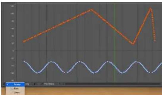
line
| Time | Series 1 | Series 2 | |------|----------|----------| | 0 | 30 | -10 | | 1 | 35 | -8 | | 2 | 40 | -6 | | 3 | 45 | -4 | | 4 | 50 | -2 | | 5 | 55 | 0 | | 6 | 60 | 2 | | 7 | 55 | 4 | | 8 | 50 | 6 | | 9 | 45 | 8 | | 10 | 40 | 10 | | 11 | 35 | 12 | | 12 | 30 | 14 | | 13 | 25 | 16 | | 14 | 20 | 18 | | 15 | 15 | 20 | | 16 | 10 | 22 | | 17 | 5 | 24 | | 18 | 0 | 26 | | 19 | -5 | 28 | | 20 | -10 | 30 | | 21 | -15 | 32 | | 22 | -20 | 34 | | 23 | -25 | 36 | | 24 | -30 | 38 | | 25 | -35 | 40 | | 26 | -40 | 42 | | 27 | -45 | 44 | | 28 | -50 | 46 | | 29 | -55 | 48 | | 30 | -60 | 50 | | 31 | -65 | 52 | | 32 | -70 | 54 | | 33 | -75 | 56 | | 34 | -80 | 58 | | 35 | -85 | 60 | | 36 | -90 | 62 | | 37 | -95 | 64 | | 38 | -100 | 66 | | 39 | -105 | 68 | | 40 | -110 | 70 | | 41 | -115 | 72 | | 42 | -120 | 74 | | 43 | -125 | 76 | | 44 | -130 | 78 | | 45 | -135 | 80 | | 46 | -140 | 82 | | 47 | -145 | 84 | | 48 | -150 | 86 | | 49 | -155 | 88 | | 50 | -160 | 90 | | 51 | -165 | 92 | | 52 | -170 | 94 | | 53 | -175 | 96 | | 54 | -180 | 98 | | 55 | -185 | 100 | | 56 | -190 | | | 57 | -195 | | | 58 | -200 | | | 59 | -205 | | | 60 | -210 | | | 61 | -215 | | | 62 | -220 | | | 63 | -225 | | | 64 | -230 | | | 65 | -235 | | | 66 | -240 | | | 67 | -245 | | | 68 | -250 | | | 69 | -255 | | | 70 | -260 | | | 71 | -265 | | | 72 | -270 | | | 73 | -275 | | | 74 | -280 | | | 75 | -285 | | | 76 | -290 | | | 77 | -295 | | | 78 | -300 | | | 79 | -305 | | | 80 | -310 | | | 81 | -315 | | | 82 | -320 | | | 83 | -325 | | | 84 | -330 | | | 85 | -335 | | | 86 | -340 | | | 87 | -345 | | | 88 | -350 | | | 89 | -355 | | | 90 | -360 | | | 91 | -365 | | | 92 | -370 | | | 93 | -375 | | | 94 | -380 | | | 95 | -385 | | | 96 | -390 | | | 97 | -395 | | | 98 | -400 | | | 99 | -405 | | | | | | | (Points) (X-axis) (Y-axis) (Line) (Y-axis) (Points) (Y-axis) (Line) (Points) (X-axis) (Points) (X-axis) (Points) (X-axis) (X-axis) (X-axis) (X-axis) (X-axis) (X-axis) (X-axis) (X-axis) (X-axis) (X-axis) (X-axis) (X-axis) (X-axis) (X-axis) (X-axis) (X-axis) (X-axis) (X-axis) (X-axis) (X-axis) (X Axis) (X Axis) (X Axis) (X Axis) (X Axis) (X Axis) (X Axis) (X Axis) (X Axis) (X Axis) (X Axis) (X Axis) (X Axis) (X Axis) (X Axis) (X Axis) (X Axis) (X Axis) (X Axis) (X Axis) (X Axis) (X Axis) (X Axis) (X Axis) (X Axis) (X Axis) (X Axis) (X Axis) (X Axis) (X Axis) (X Axis) (X Axis) (X Axis) (X Axis) (X Axis) (X Axis) (X Axis) (X Axis) (X Axis) (X Axis) (X Axis) (X Axis) (X Axis) (X Axis) (X Axis) (X Axis) (X Axis) (X Axis) (X Axis) (X Axis) (X Axis) (X Axis) (X Axis) (X Axis) (X Axis) (X Axis) (X Axis) (X Axis) (X Axis) (X Axis) (X Axis) (X Axis) (X Axis) (X Axis) (X Axis) (X Axis) (X Axis) (X Axis) (X Axis) (X Axis) (X Axis) (X Axis) (X Axis) (X Axis) (X Axis) (X Axis) (X Axis) (X Axis) (X Axis) (X Axis) (X Axis) nan / . . . . . . . . . . . . . . . . . . . . . . . . . . . . . . . . . . . . . . . . . . . . . . . . . . . nan / nan / . nan / nan / nan / nan / nan / nan / nan / nan / nan / nan / nan / nan / nan / nan / nan / nan / nan / nan / nan / nan / nan / nan / nan / nan / nan / nan / nan / nan / nan / nan / nan / nan / nan / nan / nan / nan / nan / nan / nan / nan / nan / nan / nan / nan / nan / nan / nan / nan / nan / nan / nan / nan / nan / nan / nan / nan / nan / nan / nan / nan / nan / nan / nan / nan / nan / nan / nan / nan / nan / nan / nan / nan / nan / nan / nan / nan / nan / nan / nan / nan / nan / nan / nan / nan / nan / nan / nan / nan / nan / nan / nan / nan / nan / nan / nan / nan / nan / nan / nan / nan / nan / T , T , T , T , T , T , T , T , T , T , T , T , T , T , T , T , T , T , T , T , T , T , T , T , T , T , T , T , T , T , T , T , T , T ,T , T , T , T , T , T , T , T , T , T , T , T , T , T , T , T , T , T , T , T , T , T , T , T , T , T , T , T , T , T , T , T , T ,T. X (-1, +1, +2, +3, +4, +5, +6, +7, +8, +9, +10, +11, +12, +13, +14, +15, +16, +17, +18, +19, +20, +21, +22, +23, +24, +25, +26, +27, +28, +29, +30, +31, +32, +33, +34, +35, +36, +37, +38, +39, +40, +41, +42, +43, +44, +45, +46, +47, +48, +49, +50, +51, +52, +53, +54, +55, +56, +57, +58, +59, +60, +61, +62, +63, +64, +65, +66, +67, +68, +69, +70, +71, +72, +73, +74, +75, +76, +77, +78, +79, +80, +81, +82, +83, +84, +85, +86, +87, +88, +89, +90, +91, +92, +93, +94, +95, +96, +97, +98, +99, +100 | [Value] | [Value] | [Value] | [Value] | [Value] | [Value] | [Value] | [Value] | [Value] | [Value] | [Value] | [Value] | [Value] | [Value] | [Value] | [Value] | [Value] | [Number of Points] for each of the years from January to December. The values are calculated based on the number of points and the corresponding value of the year. The values are calculated based on the number of points and the corresponding value of the year. The values are calculated based on the number of points and the corresponding value of the year. The values are calculated based on the number of points and the corresponding value of the year. The values are calculated based on the number of points and the corresponding value of the year. The values are calculated based on the number of points and the corresponding value of the year. The values are calculated based on the number only at each point. The values are calculated based on the number of points and the corresponding value of the year. The values are calculated based on the number of points and the corresponding value of the year. The values are calculated based on the number of points and the corresponding value of the year. The values are calculated based on the number of points and the corresponding value of the year. The values are calculated based on the number of points and the corresponding value of the year. The values are calculated based on the number with a specified value of the year. The values are calculated based on the number with a specified value of the year. The values are calculated based on the number with a specified value of the year. The values are calculated based on the number with a specified value of the year. The values are calculated based on the number with a specified value of the year. The values are calculated based on the number with a specified value of the year. The values are calculated based on the number with a specified value of the city. The values are calculated based on the number with a specified value of the city. The values are calculated based on the number with a specified value of the city. The values are calculated based on the number with a specified value of the city. The values are calculated based on the number with a specified value of the city. The values are calculated based on the number with a specified value of the city. The values are calculated based on the number with a specified value of the city. The values for each city are calculated by summing up to that point and summing up to that city. However, The data is not provided in this case as it is not available in this case. This is a sample size of approximately one standard deviation from a normal distribution. The actual data will vary due to random nature and lack of statistical information. Please provide a sample size of about one standard deviation from a normal distribution. The actual data will have more than one standard deviation from a normal distribution. Please provide a sample size of about one standard deviation from a normal distribution. The actual data will have more than one standard deviation from a normal distribution. Please provide a sample size of about one standard deviation from a normal distribution. The actual data will have more than one standard deviation from a normal distribution. Please provide a sample size of about one standard deviation from a normal distribution. The actual data will have more than one standard deviation from a normal distribution. Please provide a sample size of about one specific deviation from a normal distribution. The actual data will have more than one standard deviation from a normal distribution. Please provide a sample size of about one specific deviation from a normal distribution. The actual data will have more than one standard deviation from a normal distribution. Please provide a sample size of about one specific deviation from a normal distribution. The actual data will have more than one standard deviation from a normal distribution. Please provide a sample size of about one specific deviation from a normal distribution. The actual data may be estimated based on the true quantile of the data set by the code execution method. However, The actual data may be estimated based on the true quantile of the data set by the code execution method. However, The actual data may be estimated based on the true quantile of the data set by the code execution method. However, The actual data may be estimated based on the true quantile of the data set by the code execution method. However, The actual data may be estimated based on the true quantile of the data set by the code execution method. However, The actual data may have higher estimates than expected by which there is no estimate in this case. The actual data may have higher estimates than expected by which there is no estimate in this case. The actual data may have higher estimates than expected by which there is no estimate in this case. The actual data may have higher estimates than expected by which there is no estimate in this case. The actual data may have higher estimates than expected by which there is no estimate in this case. The actual data may have higher estimates than expected by which there is no estimate in this case. The actual data may be estimated based on whether they have higher estimates than expected by which there is no estimate in this case. The actual data may have higher estimates than expected by which there is no estimate in this case. The actual data may have higher estimates than expected by which there is no estimate in this case. The actual data may have higher estimates than expected by which there is no estimate in this case. The actual data may have higher estimates than expected by which there is no estimate in this case. The actual data may have higher estimates than estimated by which there is no estimate in this case. The actual data may have higher estimates than estimated by which there is no estimate in this case. The actual data may have higher estimates than estimated by which there is no estimate in this case. The actual data may have higher estimates than estimated by which there is no estimate in this case. The actual data may have higher estimates than estimated by which there is no estimate in this case. The actual data may have higher estimates than estimated by which there is zero estimate in this case. The actual data may have higher estimates than estimated by which there is zero estimate in this case. The actual data may have higher estimates than estimated by which there is zero estimate in this case. The actual data may have higher estimates than estimated by which there is zero estimate in this case. The actual data may have higher estimates than estimated by which there is zero estimate in this case. The actual data may have higher estimates than estimated by which there is zero estimate in this case The actual data may have higher estimates than estimated by which there is zero estimate in this case. The actual data may have higher estimates than estimated by which there is zero estimate in this case. The actual data may have higher estimates than estimated by which there is zero estimate in this case. The actual data may have higher estimates than estimated by which there is zero estimate in this case. The actual data may have higher estimates than estimated by which there is zero estimate in this case. The actual data may contain multiple timescales where each row represents a single point and each column represents a different point or time scale. There are three rows representing different rows: for each row and row position; for each row and row position; for each row and row position; for each row and row position; for each row and row position; for each row and row position; for each row and row position; for each row and row position; for each row and row position; for each row and row position; for each row and row position; for each row and row position; for each row and row position; for each rows and rows positions; for each row and rows positions; for each row and rows positions; for each row and rows positions; for each row and rows positions; for each row and rows positions; for each row and rows positions; for each row and rows positions; for each row and rows positions; for each row and rows positions; for each row and rows positions; for each row and rows positions; for each row and rows positions; for each row and rows positions; [Value] | [Value] | [Value] | [Value] | [Value] | [Value] | [Value] | [Value] | [Value] | [Value] | [Value] | [Value] | [Value] | [Value] | [Value] | [Value] | [Value] | [Value] [Value] | [Value] | [Value] | [Value] | [Value] | [Value] | [Value] | [Value] | [Value] | [Value] | [Value] | [Value] | [Value] | [Value] | [Value] | [Value] | [Value]Figure 39-7: Points mode.
Bars
Bars mode (Figure 39-8 and Figure 39-9) is similar to Points mode except that a colored bar extends to the right from each event, allowing you to see the current value for each type of controller, even in portions of the track where no events of that type reside. With Event Chasing enabled (“Event Chasing” on page 224), Bars mode is a more accurate representation of what will happen
during playback because Event Chasing maintains the current value of each type of controller in the track, regardless of where playback begins.
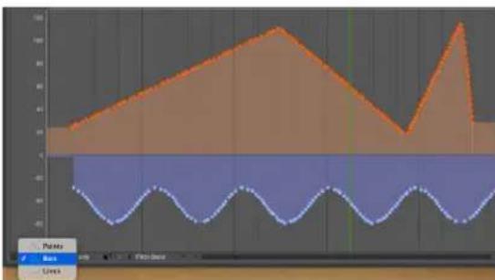
line
| Time | Line 1 | Line 2 | |------|--------|--------| | 0 | 0 | -10 | | 1 | 2 | -8 | | 2 | 4 | -6 | | 3 | 6 | -4 | | 4 | 8 | -2 | | 5 | 10 | 0 | | 6 | 8 | 2 | | 7 | 6 | 4 | | 8 | 4 | 6 | | 9 | 2 | 8 | | 10 | 0 | 10 | | 11 | -2 | 8 | | 12 | -4 | 6 | | 13 | -6 | 4 | | 14 | -8 | 2 | | 15 | -10 | 0 | | 16 | -8 | -2 | | 17 | -6 | -4 | | 18 | -4 | -6 | | 19 | -2 | -8 | | 20 | 0 | -10 | | 21 | 2 | -8 | | 22 | 4 | -6 | | 23 | 6 | -4 | | 24 | 8 | -2 | | 25 | 10 | 0 | | 26 | 8 | -2 | | 27 | 6 | -4 | | 28 | 4 | -6 | | 29 | 2 | -8 | | 30 | 0 | -10 | | 31 | -2 | -8 | | 32 | -4 | -6 | | 33 | -6 | -4 | | 34 | -8 | -2 | | 35 | -10 | 0 | | 36 | -8 | -2 | | 37 | -6 | -4 | | 38 | -4 | -6 | | 39 | -2 | -8 | | 40 | 0 | -10 | | 41 | -2 | -8 | | 42 | -4 | -6 | | 43 | -6 | -4 | | 44 | -8 | -2 | | 45 | -10 | 0 | | 46 | -8 | -2 | | 47 | -6 | -4 | | 48 | -4 | -6 | | 49 | -2 | -8 | | 50 | 0 | -10 | | 51 | -2 | -8 | | 52 | -4 | -6 | | 53 | -6 | -4 | | 54 | -8 | -2 | | 55 | -10 | 0 | | 56 | -8 | -2 | | 57 | -6 | -4 | | 58 | -4 | -6 | | 59 | -2 | -8 | | 60 | 0 | -10 | | 61 | -2 | -8 | | 62 | -4 | -6 | | 63 | -6 | -4 | | 64 | -8 | -2 | | 65 | -10 | 0 | | 66 | -8 | -2 | | 67 | -6 | -4 | | 68 | -4 | -6 | | 69 | -2 | -8 | | 70 | 0 | -10 | | 71 | -2 | -8 | | 72 | -4 | -6 | | 73 | -6 | -4 | | 74 | -8 | -2 | | 75 | -10 | 0 | | 76 | -8 | -2 | | 77 | -6 | -4 | | 78 | -4 | -6 | | 79 | -2 | -8 | | 80 | 0 | -10 | | 81 | -2 | -8 | | 82 | -4 | -6 | | 83 | -6 | -4 | | 84 | -8 | -2 | | 85 | -10 | 0 | | 86 | -8 | -2 | | 87 | -6 | -4 | | 88 | -4 | -6 | | 89 | -2 | -8 | | 90 | 0 | -10 | | 91 | -2 | -8 | | 92 | -4 | -6 | | 93 | -6 | -4 | | 94 | -8 | -2 | | 95 | -10 | 0 | | 96 | -8 | -2 | | 97 | -6 | -4 | | 98 | -4 | -6 | | 99 | -2 | -8 | | 100 | 0 | -10 |Figure 39-8: Bars mode.
The example below illustrates how the value of a single event is conveyed by the colored bar, up to the next controller event of the same time.
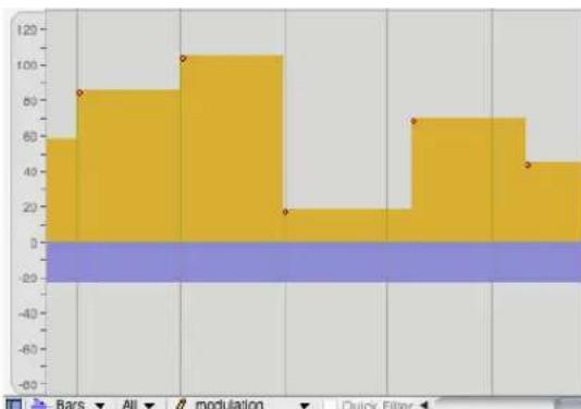
bar
| Category | Value | |---|---| | Bar | 60 | | All | 85 | | modulation | 105 | | Quick Filter | 20 | | Bar | 70 | | All | 70 | | modulation | 45 | | Quick Filter | 45 |Figure 39-9: Bars mode illustrates how the value of an individual controller is maintained until the next event of the same type in the track.
Each type of continuous data has its own color for the bars. See “Changing continuous data colors” on page 425.
Lines
In Lines mode (Figure 39-10), Digital Performer employs sophisticated interpolation to draw a line that closely approximates the contour of individual controller events.

line
| Point | Series 1 | Series 2 | |-------|----------|----------| | 1 | 30 | 40 | | 2 | 40 | 30 | | 3 | 50 | 40 | | 4 | 60 | 30 | | 5 | 70 | 40 | | 6 | 80 | 30 | | 7 | 90 | 40 | | 8 | 100 | 30 | | 9 | 90 | 40 | | 10 | 80 | 30 | | 11 | 70 | 40 | | 12 | 60 | 30 | | 13 | 50 | 40 | | 14 | 40 | 30 | | 15 | 30 | 40 | | 16 | 20 | 30 | | 17 | 10 | 40 | | 18 | 0 | 30 | | 19 | -10 | 40 | | 20 | -20 | 30 | | 21 | -30 | 40 | | 22 | -40 | 30 | | 23 | -50 | 40 | | 24 | -60 | 30 | | 25 | -70 | 40 | | 26 | -80 | 30 | | 27 | -90 | 40 | | 28 | -100 | 30 | | 29 | -90 | 40 | | 30 | -80 | 30 | | 31 | -70 | 40 | | 32 | -60 | 30 | | 33 | -50 | 40 | | 34 | -40 | 30 | | 35 | -30 | 40 | | 36 | -20 | 30 | | 37 | -10 | 40 | | 38 | 0 | 30 | | 39 | 10 | 40 | | 40 | 20 | 30 | | 41 | 30 | 40 | | 42 | 40 | 30 | | 43 | 50 | 40 | | 44 | 60 | 30 | | 45 | 70 | 40 | | 46 | 80 | 30 | | 47 | 90 | 40 | | 48 | -10 | -30 | | 49 | -20 | -40 | | 50 | -30 | -30 | | 51 | -40 | -40 | | 52 | -50 | -30 | | 53 | -60 | -40 | | 54 | -70 | -30 | | 55 | -80 | -40 | | 56 | -90 | -30 | | 57 | -100 | -40 | | 58 | -90 | -30 | | 59 | -80 | -40 | | 60 | -70 | -30 | | 61 | -60 | -40 | | 62 | -50 | -30 | | 63 | -40 | -40 | | 64 | -30 | -30 | | 65 | -20 | -40 | | 66 | -10 | -30 | | 67 | 0 | -40 | | 68 | 10 | -30 | | 69 | 20 | -40 | | 70 | 30 | -30 | | 71 | 40 | -40 | | 72 | -1 | -3 | | 73 | -2 | -4 | | 74 | -3 | -3 | | 75 | -4 | -4 | | 76 | -5 | -3 | | 77 | -6 | -4 | | 78 | -7 | -3 | | 79 | -8 | -4 | | 80 | -9 | -3 | | 81 | -10 | -4 | | 82 | -9 | -3 | | 83 | -8 | -4 | | 84 | -7 | -3 | | 85 | -6 | -4 | | 86 | -5 | -3 | | 87 | -4 | -4 | | 88 | -3 | -3 | | 89 | -2 | -4 | | 90 | -1 | -3 | | 91 | 1 | -4 | | 92 | 2 | -3 | | 93 | 3 | -4 | | 94 | 4 | -3 | | 95 | -1 | -4 | | 96 | -2 | -3 | | 97 | -3 | -4 | | 98 | -4 | -3 | | 99 | -5 | -4 | | Note: The data is extracted from the code and presented in CSV format as requested. The values for 'Points' and 'Rank' are not provided in the code. There is only one data series in the output box. The values for 'Points' and 'Rank' are estimated based on the input data. There is no additional data series in this case. I have provided the output data as follows: "Points" and "Rank".Figure 39-10: Bars mode.
THE CONTINUOUS DATA RULER
All continuous MIDI data has a value range from 0 to 127 except pitch bend, which has a value range from -8192 to 8191. Because of these two separate scales, the Continuous Data Ruler provides three different scales:
- a controller scale from 0 to 127, whose origin rests at the bottom of the window:
- a pitch bend scale from -8192 to 8191, whose origin appears in the middle of the window:
- a combination scale from -80 to 127, which combines the above two scales and whose origin appears just below the middle of the window.

line
| Scale | Value | | ------------------ | ----- | | Controller scale | 0 | | Pitch bend scale | 0 | | Combination scale | 0 |To switch from one scale to another, click in the ruler. Doing so toggles from the current scale to the next. Each scale displays data appropriate to that scale. The controller scale (0 to 127) displays controller data only. The pitch bend scale (-8192 to 8191) displays pitch bend only. The combination scale (-80 to 127) displays controller data and pitch bend together. Note velocities, if selected in the View Filter, appear in the controller and combination scales. The pitch bend scale displays pitch bend even if it is deselected in the View Filter.
All three scales provide numbered marks in the ruler and an origin line extending to the right that indicates where zero is on the ruler.
When viewing one continuous data type at a time with the Insert menu filter (Figure 39-12 on page 425), the ruler displays the scale appropriate for that data type.
SHOWING/HIDING CONTINUOUS DATA TYPES
The expression continuous data type refers to a kind of continuous data. For example, pitch bend is one kind of continuous data. Controller #7 (volume) is another type. The Continuous Data Grid displays all continuous data types at once. At times it is useful to be able to see all at the same time, or several, or even just one data type by itself. There are several ways to show and hide continuous data types as needed. Except in the case of time range selections made in the time ruler, data that is visible is affected by edits; data that is hidden is not.
The View Filter
You can place the View Filter window next to the MIDI Editor window to show and hide data as needed in the Continuous Data Grid. See "View Filter" on page 328.
The 'Show only' Filter
When the Show only check box is checked, it hides all continuous data types in the Continuous Data Grid except those for which at least one event is selected. For example, if you select a controller #3 event and click the Show-only check box, all controller #3's will remain visible and all other data types, such as pitch bend and velocities, will disappear. To make the other data types reappear, uncheck the Show only check box.

line
| Time Point | Volume | | ---------- | ------ | | 1 | 40 | | 2 | 35 | | 3 | 30 | | 4 | 25 | | 5 | 20 | | 6 | 15 | | 7 | 10 | | 8 | 5 | | 9 | 0 |Figure 39-11: The Show-only check box lets you quickly "solo" (visually) the type of continuous data currently selected
The Insert menu filter
The Insert menu filter lets you choose a single data type for Pencil tool insertion. In addition, the ruler automatically switches to the appropriate scale. To
temporarily hide all other data types in the grid, click the Insert menu filter check box, shown below.

Figure 39-12: The Insert menu filter.
The Pitch Bend ruler
To view pitch bend data by itself, click on the Continuous Data Ruler. Doing so toggles the ruler among three displays, one which displays pitch bend data by itself. See “The Continuous Data Ruler” on page 423.
CONT. DATA ICONS
The Continuous Data Icons preferences display icons for each type of MIDI continuous controller data (for viewing the data in Points or Bars mode). All 128 continuous data types are represented with thirteen different data type icons to help you differentiate between them on the continuous data grid. As shown in Figure 39-13 below, six of the icons are reserved and seven can be assigned to any data type you wish. Any data type that is not assigned to one of the first 7 icons is displayed with the All Others icon. To assign a data type to an icon, type its number into the box next to the icon. Because more than eight types of controllers exist, the most commonly used controllers have been assigned to icons by default. However, you can change which controller an icon represents. For example, a square can represent controller #7 or controller #38. All controllers that have not been assigned to one of the first seven icons are automatically assigned to the last "u"-shaped icon. The icons for pitch bend, velocity, and key pressure cannot be changed and are displayed for reference.
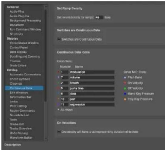
Figure 39-13: Continuous Data Icons preferences.
CHANGING CONTINUOUS DATA COLORS
When viewing multiple data types in Bars mode (Figure 39-8), you may wish to change the color of the continuous data bars to better distinguish each continuous data type. To change a continuous data color:
1 Select at least one event of the continuous data type you wish to change.
2 From the View menu, choose Colors>Set Continuous Data Color.
The standard macOS or Windows color picker appears. Choose the desired color and click OK.


Clearing a continuous data color
To clear a continuous data color (set it to a neutral gray), select at least one event and then choose Colors>Clear Continuous Data Color from the View menu.
Reverting to a default color
To revert to the default color for a continuous data type, select at least one event and then choose Colors>Reset Continuous Data Color to Default from the View menu.
NOTE VELOCITIES
Note-on and -off velocities are displayed and edited in the Continuous Data Grid directly below the note. An on velocity appears as a small “ 1 ” directly below the beginning of the note bar, and an off velocity appears as a small “^” directly below the release. If a note is selected, its velocity icons will be selected with the note.

Figure 39-14: How note velocities are displayed in the continuous controller grid.
Displaying on-velocities in this manner allows you to edit them in the same ways as continuous data. For example, you can create a crescendo or decrescendo simply by editing on-velocities in the Continuous Data Grid. See “Editing continuous data in Points or Bars mode” on page 427 called for more information.
On-velocities cannot be dragged horizontally (in time). To move them, drag the note itself (or its duration).
Off-velocities are displayed in the continuous data grid for reference only; they cannot be graphically edited. On-velocities can be edited.
Both on- and off-velocities are hidden in Lines mode, since they are bound to their parent notes and cannot be generated in streams like continuous data.
On-velocity tails
Note-on velocities are displayed with a tail (Figure 39-14) that indicates the note's duration. You can choose to hide the tail with the On Velocities preference (Figure 39-13 on page 425).
Hiding velocities
You can hide velocities using any of the methods covered in “Showing/hiding continuous data types” on page 424.
EDITING CONTINUOUS DATA IN POINTS OR BARS MODE
The procedures for inserting, selecting and editing continuous data are the same for both Points and Bars mode. Lines mode handles these operations somewhat differently, as explained later in “Editing continuous data in Lines mode” on page 429.
Inserting continuous data in Points or Bars mode
To insert continuous data in Points or Bars mode:
1 Click the Pencil tool in the Tool palette (Figure 39-15).
2 If you will be inserting a stream of continuous data, choose the desired shape of the curve from the Pencil/Reshape Curve menu in the Tool palette.
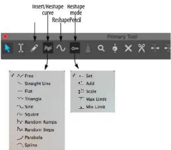
Figure 39-15: Choosing a shape for inserting a continuous data curve.
3 If you would like the curve shape you have selected to snap to beats or a similar metric grid, set the Edit Resolution and turn on the Edit Grid (see "Snap Information" on page 355).
Doing so constrains periodic waveshapes to the resolution of the edit grid. For example, if the Edit Grid is set to a quarter note, and you insert a sine wave, the sine wave will cycle once each quarter note.
4 Choose the desired data type from the Insert menu shown below in Figure 39-16, or choose the desired data type from the Insert menu (Figure 39-16), which hides all other data types and restricts insertion to the type of data being viewed.

Figure 39-16: The Insert menu.
5 Insert data as follows:
To do this: Do this:
| To insert a single event | Click on the grid with the Pencil. |
| To insert a stream of events | Drag the Pencil. A stream of data is inserted according to the curve shape that you chose in the Tool palette. You can conform to a beat grid with Edit Resolution as explained in “Constraining a periodic waveform to beats” on page 428, and you can use the waveform modifier keys described in “Using modifier keys to control period, phase, and other waveform parameters” on page 428. |

natural_image
Abstract geometric pattern with five black triangular shapes on a gray background (no text or symbols)Figure 39-17: Inserting a periodic waveform. In this example, a triangle curve is being inserted. Notice that grid snapping is on and set to a quarter note. Accordingly, the triangle wave is snapping to a quarter note grid.
Constraining a periodic waveform to beats
To insert a continuous data periodic waveform that conforms to a rhythmic grid (quarter notes, eighth notes, etc.), set the edit grid to the duration that equals one complete period of the waveform. This forces the waveform to conform to the grid duration you specify.
Using modifier keys to control period, phase, and other waveform parameters
When inserting (or reshaping) continuous data using a waveform shape as shown in Figure 39-17, you can hold down modifier keys while dragging to change waveform parameters as follows:
To control this: Hold down this key:
| Toggles grid snapping (on/off) Command/Ctrl key | |
| Phase Option/Alt key | |
| Duty cycle• Triangle wave skew• square wave pulse width• sine wave pulse width | Control/Win key |
| • Periodic frequency• Random curve density | Shift key |
To re-use the last settings for sineEscape key triangle, square, random steps or random ramps
Selecting continuous data in Points or Bars mode
To select continuous data in Points or Bars mode:
1 Click the Pointer tool in the Tool palette (Studio menu).
2 Make a selection as follows:
To do this: Do this:
| To select a single event | Click it with the pointer cursor. A stalk is drawn from the icon to the origin of the continuous data graph. |
| To select several events | Drag over the events in the grid with the cross-hair cursor. |
| To select a continuous data curve | Drag over the curve with the cross-hair cursor. Hide other data types first, if necessary (“Showing/hiding continuous data types” on page 424). |
| To select all events of one type | Double-click one event. |
| To add to the current selection | Hold down the Shift key while using any of the selection techniques above. |
| To deselect events Hold | down the Shift key while using any of the above techniques on selected data. |
| To deselect all data | Choose Deselect All from the Edit menu or press its keyboard shortcut. Or click once in any empty area in the grid. |
Dragging events in Points or Bars mode
To change the value or location of continuous data events in Points or Bars mode:
1 If desired, set the Edit Resolution (see "Snap Information" on page 355).
2 Click the Pointer tool in the Tool palette.
3 If you are modifying a single event, drag its icon to a different position or value.
Hold down the Shift key to constrain vertically or horizontally. For exact positioning, refer to the Cursor Information box and the rulers.
4 If you are modifying several events, select them first as described in the previous section, and then drag one of the selected events.
Scaling by dragging
If you hold down the Control/Win keys when dragging selected continuous controllers, they are scaled in value (vertically) and time (horizontally).
Editing the value of an event using a MIDI controller in Points or Bars mode
To change the value of an event with your MIDI controller:
1 Make sure that "MIDI Edit" is checked under the MIDI Editor mini-menu.
2 Click the event with the Pointer tool to select it.
3 Transmit a corresponding event from your MIDI controller.
For example, if you have selected pitch bend event, move the pitch bend wheel on your controller and the event will change to the new value you set with the wheel.
4 When you have entered the value you wish, press the Return key or the mouse to confirm the new value.
Reshaping data curves
You can modify continuous data with the Reshape tool. For example, you can scale, compress or limit it.
For complete details on the Reshape tool, see "Reshape tool" on page 350.
EDITING CONTINUOUS DATA IN LINES MODE
Lines Mode attempts to represent a stream of continuous data events as a straight line between two points, similar to the breakpoint automation display in audio tracks. This allows you to view and modify continuous MIDI data in a similar fashion as audio automation data. However, MIDI continuous data is fundamentally different than audio automation data: MIDI data consists of a stream of individual events, as shown below in Figure 39-18, whereas audio automation data consists of two points that prescribe a ramp. It is very important to keep this distinction in mind when working in Lines Mode because, as explained in the next few sections, MIDI Lines Mode does not always act the same way as audio automation.
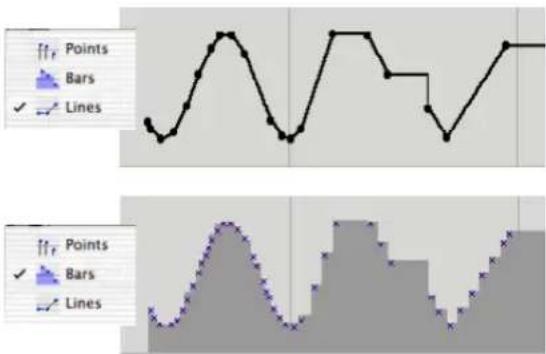
line
| Panel | Points | Bars | Lines | |-------|--------|------|-------| | Top | 1 | 0 | 0 | | Top | 2 | 1 | 0 | | Top | 3 | 2 | 0 | | Top | 4 | 3 | 0 | | Top | 5 | 4 | 0 | | Top | 6 | 5 | 0 | | Top | 7 | 6 | 0 | | Top | 8 | 7 | 0 | | Top | 9 | 8 | 0 | | Top | 10 | 9 | 0 | | Top | 11 | 10 | 0 | | Top | 12 | 11 | 0 | | Top | 13 | 12 | 0 | | Top | 14 | 13 | 0 | | Top | 15 | 14 | 0 | | Top | 16 | 15 | 0 | | Top | 17 | 16 | 0 | | Top | 18 | 17 | 0 | | Top | 19 | 18 | 0 | | Top | 20 | 19 | 0 | | Bottom | 1 | 0 | 0 | | Bottom | 2 | 1 | 0 | | Bottom | 3 | 2 | 0 | | Bottom | 4 | 3 | 0 | | Bottom | 5 | 4 | 0 | | Bottom | 6 | 5 | 0 | | Bottom | 7 | 6 | 0 | | Bottom | 8 | 7 | 0 | | Bottom | 9 | 8 | 0 | | Bottom | 10 | 9 | 0 | | Bottom | 11 | 10 | 0 | | Bottom | 12 | 11 | 0 | | Bottom | 13 | 12 | 0 | | Bottom | 14 | 13 | 0 | | Bottom | 15 | 14 | 0 | | Bottom | 16 | 15 | 0 | | Bottom | 17 | 16 | 0 | | Bottom | 18 | 17 | 0 | | Bottom | 19 | 18 | 0 | | Bottom | 20 | 19 | 0 | | Bottom (Top) - Bar (Points) - Bars - Lines - Lines (Top) - Bars - Lines (Bottom) - Bars - Lines (Top) - Bars - Lines (Bottom) - Bars - Lines (Top) - Bars - Lines (Bottom) - Bars - Lines (Top) - Bars - Lines (Bottom) - Bars - Lines (Bottom) - Bars - Lines (Bottom) - Bars - Lines (Bottom) - Bars - Lines (Bottom) - Bars - Lines (Bottom) - Bars - Lines (Bottom) - Bars - Lines (Bottom) - Bars - Lines (Bottom) - Bars - Lines (Bottom) - Bars - Lines (Bottom)Figure 39-18: Volume controller data displayed in Lines Mode and Bars Mode. Notice the stair-steps in Bars mode—a more accurate representation of the MIDI events that underlie the points and lines in Lines Mode. Lines Mode can be convenient for inserting and editing continuous data, but Bars mode tells you 'what's really going on' with the individual events.
MIDI data versus audio ramps
The lines and points in Lines Mode look very similar to ramp automation in audio tracks. Editing MIDI continuous data in Lines Mode is very similar to audio track break-point automation. However, in the Continuous Data grid, these lines are based on individual MIDI events, as you can see above in Figure 39-18. If you switch to Points or Bars mode, you can see the individual events at any time.
Because MIDI continuous data is really a stream of individual events, as opposed to audio automation ramps, which are straight lines calculated with single sample-accuracy between control points, you may sometimes encounter stair-steps and other situations that do not occur in audio tracks. Again, you can always switch to Bars mode for a more clear idea of what's going on with the events that lie beneath the lines.
Points, stair-steps and ramps
Lines Mode employs three elements to represent continuous data streams: ramps, points and stair-steps.
Ramps
Ramps are straight lines drawn between two points. Lines Mode draws a ramp when continuous data events are close enough and straight enough to be drawn as a line. The distance between events that is required for them to be interpreted as a line can be adjusted with the Ramp Density setting (explained in the next section).
Points
A point consists of a continuous data event that falls between two ramps that have different slopes. The point consists of an actual MIDI data event; by moving it such that it falls more in line with events around it, you can actually make it ‘disappear’ when it crosses the threshold for being interpreted as part of the ramp.

Figure 39-19: Ramps and points in Lines Mode. Notice that the selected point is actually a selected event (shown in Bars mode).
Steps
Lines Mode displays a step (as shown below in Figure 39-20) when consecutive events are too far apart to be interpreted as a line. As you can see, a step, gives you an accurate representation of the underlying data, and the effect it will have when it is played back.

Figure 39-20: A step in Lines Mode.
Ramp density
Ramp density is the distance between events that is required for them to be interpreted as a line. The default ramp density is 90 ticks (at 480 ticks per quarter note); this default value produces good results in most situations. The Set Ramp Density command in the MIDI Editor mini-menu lets you adjust the ramp density as follows:
To achieve this: Do this:
To see fewer stair-steps Raise the ramp density
To see more control points Lower the ramp density
Ramp Density also controls the time interval between MIDI continuous data events that are automatically generated when editing lines and points in Lines Mode. A lower number produces higher density (more data per unit of time) and greater resolution. For example, if the changes in volume of a particular MIDI instrument in your setup are not smooth enough, you could choose a
lower number for the Ramp Density. (Be sure to redraw the curve after doing so to generate new data.) A higher Ramp Density number reduces the density, lowering the amount of overall data produced. For example, you might find that a particular MIDI instrument might not be able to handle so much data. In this case, you can raise the Ramp Density number to send it less data.
Working with Lines Mode
Use the following techniques in Lines Mode:
To do this: Do this:
| To insert a point Click with the Pencil tool. | |
| To add a point to an existing line | Click with the Pencil tool on the line and drag a little bit. If you don't drag, the newly inserted event will be interpreted as part of the line, and it won't remain an independent point. |
| To move a point Drag it with the Pointer tool. | |
| To delete a point Remember, underlying a point (and the lines extending from it), there is an entire stream of events. Deleting one point only deletes one event, but there are many more right next to it, so it may seem like it is not being deleted properly. Instead, try dragging an adjacent point past the one you want to delete. Or make a time range selection with the Pointer tool—and perhaps even switch to Bars Mode or Points Mode—to delete the stream of events that prescribes the point. | |
| To remove a step Grab the corner of the step (or anywhere on the horizontal part of it) with the Pointer tool and drag as desired. | |
| To insert a waveform or reshape an existing line with a waveform | Choose the Pencil tool, choose a reshape curve as shown in Figure 39-15 on page 427), and then drag horizontally in the grid. You can conform to a beat grid with Edit Resolution as explained in “Constraining a periodic waveform to beats” on page 428, and you can use the waveform modifier keys described in “Using modifier keys to control period, phase, and other waveform parameters” on page 428. |
Region operations in Lines Mode
Region operations, such as cut, copy, paste and change continuous data do not always have the same affect on MIDI data in Lines Mode and audio automation ramps. In the example below (Figure 39-21), both MIDI data and audio data
display a single point within the time range selection. However, as you can see in Bars Mode (bottom row), there are actually many selected MIDI events, not just one. If continuous data scaling is applied (second column), the single audio control point scales by itself, whereas all of the selected MIDI events scale together, producing a different final result. Note: to get the same result with MIDI as audio in this example, you could simply drag the control point in the MIDI track downwards.

Figure 39-21: Region operations like Change Continuous Data have a different effect on MIDI data and audio automation data.
THE MEDIAN STRIP
The Median Strip separates the Note Grid from the Continuous Data Grid. It contains only the following discrete MIDI events: patch changes, mode changes, switch controllers like #64 (sustain pedal), tune requests, song changes, mute automation events and system exclusive events. Notes and continuous data do not appear in the Median Strip.
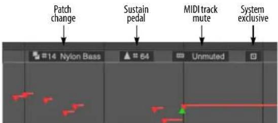
Figure 39-22: The Median Strip shows MIDI events that aren't notes and are not continuous, such as patch change events and system exclusive events.
Moving the Median Strip
The Median Strip serves as the border between the Note Grid and the Continuous Data Grid. It can be dragged up and down by its handle on the left edge. Moving the Median Strip resizes the Note Grid and the Continuous Data Grid proportionally. For example, if you drag the Median Strip down as far as it will go, you will see only the Note Grid. If you drag the Median Strip all the way up, you will see only the Continuous Data Grid.
Working with discrete MIDI events in the Median Strip
Events in the Median Strip do not have durations. Each event is therefore displayed as a single item inside a small box. Patch changes, system exclusive events, Mute Automation events, and controllers are displayed with their Event List icon; mode changes are displayed as text, such as "Poly" or "Omni on". An event may be edited in the Information Bar in the same fashion as in the Event List. Location is determined by the Main Time Ruler. To indicate time location, the vertical grid lines from the Main Ruler extend through the Median Strip.
Inserting an event in the Median Strip
Discrete MIDI events that are not continuous data, such as patch changes, mode changes, switch controllers like #64 (sustain pedal), and system exclusive events, appear in the Median Strip. To insert such an event:
1 If desired, set the Edit Resolution and turn on the Edit Grid (see "Snap to Grid" on page 355).
2 Click the Pencil tool in the Tool palette (Studio menu).
3 Choose the desired data type from the Insert menu (Figure 39-16 on page 427).
4 Click once at the desired time location in the Median Strip.
The event will appear where you clicked.
Editing an Event in the Median Strip
Some median strip events, such as patch changes and mute automation events, can be edited directly in the Median Strip. For other event types, their parameters can be edited in the Information Bar. Click the event to select it and then edit parameters as desired in the Information Bar.
Drag an event in the Median Strip to change its location.
If two or more events occur at the same time, they are displayed as a menu as shown below:
![[MIDI Track Mute] [Unmuted] #14 81 1 Nylon Bass](/content/2026/05/834832/images/1ae822330f922f4394ab19691248a2d88f8711214063c1c8ca24837bf8b3b2d2.jpg)
Figure 39-23: When items in the Median Strip occur very close to one another (or even on the same exact tick), the Median Strip displays the menu icon shown here. Click the menu to see the events; you can select them by choosing them from the menu.
ZOOMING
Digital Performer provides many ways to zoom in and out, including many useful zooming shortcuts. In particular, you can very quickly and conveniently zoom in and out by Control/Windragging vertically on the green playback wiper. For details, see “Zooming with the wiper” on page 228. For general zooming techniques, see “Zooming” on page 331 and “Zoom menu shortcuts” on page 332. See the sections below for abilities specific to the MIDI Editor.
Note grid zooming
Time and Pitch can be zoomed independently. For example, you can zoom out the Time Ruler to see more measures at one time, and zoom in the Pitch Ruler to focus on a specific pitch range.
With the Pitch Ruler, zooming out reduces the height of each pitch, allowing you to see more octaves at once; zooming in enlarges the height of each pitch, allowing you to focus on a particular pitch range.

Figure 39-24: Note grid zoom control.
You can also zoom the note grid with the scroll wheel on your mouse or the trackpad on your laptop. See "Zooming with the scroll wheel" on page 331 and "Zooming with a track pad" on page 331.
GRAPHIC EDITING TECHNIQUES
All of Digital Performer's powerful editing features are available in the MIDI Editor; refer to "Graphic editing techniques" on page 334.
THE VIEW FILTER
In the MIDI Editor, the View Filter serves two useful functions. It allows you to control what types of data you can see and edit in the window. In essence, the View Filter acts like an edit filter: if a type of data, such as pitch bend, is visible in the window, it will be affected by editing commands. If the data type is not visible in the window, it cannot be edited.
For information about using the View Filter, see "View Filter" on page 328.
SCROLLING DURING PLAYBACK
The Auto Scroll command (View menu > Scroll) controls how the MIDI Editor scrolls during playback. For example, the playback wiper can travel across the window, or the window can scroll beneath a stationary wiper that remains anchored in the middle of the window. See “Auto scroll” on page 226.
SCRUBBING IN THE MIDI EDITOR
There are two ways to scrub in the MIDI Editor:
- With the playback wiper — scrubs all play-enabled MIDI tracks. For more information, see “Scrubbing multiple MIDI tracks” on page 229.
- With the Scrub tool (Figure 39-1 on page 412) — when you drag horizontally in the note grid, you'll hear only the tracks currently shown (with the Track selector).
EDITING IN THE CONDUCTOR TRACK
The Conductor Track Editor is similar to a regular track but has several differences. It does not have a Note Grid because the Conductor Track cannot contain notes. In addition, the Median Strip is wider and fixed at the top of the window just below the Time Ruler. Finally, the Conductor Track has a Tempo Change Grid similar to the Continuous Data Grid that displays tempo changes only.
Meter changes, key changes, and markers are displayed in the Median Strip.
The Conductor Track Median Strip
The Median Strip in the Conductor Track functions much like the Median Strip in a regular track. Each meter change, key change, and marker is displayed as a single item. The Conductor Track Median Strip is wide enough to accommodate all three kinds of events without overlapping.
Editing in the Conductor Track Median Strip works the same as editing MIDI data in a regular track's median strip: click an item to make it appear in the Information Bar and click in the Information Bar to edit its values; drag the item left or right to change its location.
Inserting a meter/key change
To insert a meter change or key change:
1 If desired, set the Edit Resolution and turn on Snap to Grid (see "Snap to Grid" on page 355).
2 Click the Pencil tool in the Tool palette (Studio menu).
3 Click once at the desired time location and vertical position in the Median Strip as shown below:

Figure 39-25: To insert a meter change with the Pencil tool, click in the top third of the Median Strip; for key changes, click in the middle.
Working with markers
Double-click a marker to change its name. To insert or delete markers, use the Markers Window (Project menu).
Editing the location of a meter change, key change, or marker
To change the location of an item in the median strip:
1 Click the item you wish to move and drag left to advance it or drag right to delay it.
The event will move to the new location when you release the mouse.
Moving meter changes can produce partial measures and other situations that require an in-depth knowledge of how meter changes work. Before dragging meter changes, be sure to review chapter 59, “Change Meter” (page 749).
The Tempo Change Grid
Tempo changes are displayed and edited on the Tempo Change grid in the same fashion as continuous data, except that the Tempo Grid is displayed in Bars mode only. Each tempo change event is displayed on the grid as a small icon with a colored bar extending to its right until the next tempo event. When the tempo change event is selected, a line extends from its icon to the origin at the bottom of the grid. A tempo change ruler on the left measures events on the grid. Tempo changes can be selected and edited in the same way as a selected continuous data type. For more information, “Editing continuous data in Points or Bars mode” on page 427.
Inserting tempo changes
Follow the same procedure for inserting continuous data. See “Inserting continuous data in Points or Bars mode” on page 427.
Getting Digital Performer to follow tempo changes
Digital Performer follows tempo changes when it is placed in Conductor Track tempo mode. For details, see chapter 58, “Change Tempo” (page 741).
Zooming the Tempo Ruler
The Tempo ruler in the Conductor track can be zoomed in for more precise tempo editing. Clicking the Tempo ruler toggles quickly between your custom zoom scale and the normal scale.
To zoom the Tempo ruler, drag over the range of values you wish to zoom. The Tempo ruler will zoom in on the range that you select. Then click the Tempo ruler to toggle between your custom zoom scale and the normal scale.

Figure 39-26: You can zoom in the Tempo Ruler to get better resolution when editing tempos. Just drag over the range you want to zoom in on, and then click the ruler to toggle between the zoomed in range and the normal range.
CLIPS IN THE MIDI EDITOR
Clips (and the data they contain) do not appear in the MIDI Editor. Instead, view and edit them in the Sequence Editor (see “Working with Clips” on page 400) and the Clip Editor (see “The Clip Editor” on page 295).
CHAPTER 40 Event List
OVERVIEW
The Event List is one of several edit windows in Digital Performer. To learn more about editors in general, see chapter 35, “Edit Windows” (page 339).
The Event List displays track data as a chronological list of “events”. Examples of events are MIDI notes, audio soundbites, MIDI controller data, audio volume events, and program (patch) changes. Other information that occurs in specific time locations can be displayed in an Event List as well: markers, meter changes, key changes, tempo changes, and loop points. The Event List can be used to edit individual events or select a region of events for editing with menu commands. Event Lists for different tracks can be open at one time. Event Lists can be opened, scrolled, and edited during playback.
For a window which shows only one event at a time, the currently selected event, see “Event Information” on page 359.
Quick Reference....437
Event List mini-menu....438
Event List title bar ....438
Event List basics ....438
Types of events....439
MIDI Data 439
Audio data ....443
Mix automation data....444
Clips and Conductor Track data ....444
Inserting data in the Event List....445
Editing data in the Event List....446
Event List hints 448
QUICK REFERENCE
![Insert button Remove button menu Text box View filter Event Insert Selected events Event List: Pulsing Pad Mono Pressure Pulsing Pad 1[1]000 A section 4/4 click A3 65 51 31/430 → 8/4/450 F#3 49 50 5/424 → 2/2/424 Db3 60 38 5/429 → 2/2/429 1[1]011 58 1[1]056 70 1[2]125 30 2[2]438 B2 89 ↑ 61 ↔ 1/435 → 2/4/393 2[2]442 E3 88 ↑ 45 ↔ 1/442 → 2/4/404 2[2]455 Ab3 69 ↑ 64 ↔ 1/471 → 2/4/446 2[3]164 256 2[3]210 768 2[3]256 896 2[3]347 768 2[3]393 384 2[3]439 128 2[4]005 -256 2[4]050 -384 2[4]414 F#3 78 ↑ 67 ↔ 5/440 → 4/2/374 2[4]426 D3 73 ↑ 65 ↔ 5/460 → 4/2/405 2[4]446 A2 78 ↑ 58 ↔ 5/399 → 4/2/365 4[2]400 B2 100 ↑ 59 ↔ 2/032 → 4/4/432 4[2]413 E3 88 ↑ 52 ↔ 1/456 → 4/4/390 4[2]417 Ab3 83 ↑ 62 ↔ 2/024 → 4/4/441 4[4]418 F#3 84 ↑ 42 ↔ 5/472 → 6/2/410 4[4]420 Db3 83 ↑ 79 ↔ 5/462 → 6/2/402 6[2]429 B2 92 ↑ 65 ↔ 1/380 → 6/4/329 6[2]430 E3 88 ↑ 42 ↔ 1/395 → 6/4/345 6[2]434 Ab3 53 ↑ 55 ↔ 1/439 → 6/4/392 6[4]381 D3 76 ↑ 75 ↔ 6/056 → 8/2/437 6[1]385 F#3 73 ↑ 78 ↔ 5/060 → 8/2/435](/content/2026/05/834832/images/a3c259695e842d98ad91e0d379139694a8756bff871511e2a28efc84713a8144.jpg)
Figure 40-1: Digital Performer's Event List gives you a precise, numerical look at the data in a track. This is a MIDI track.
Insert menu: Chooses what kind of data will be inserted by the Insert button.
Insert button: Inserts an event of the data type shown in the Insert menu. Option/Alt-click to reinsert another event of the type just inserted.
Remove button: Removes the selected events.
Text box: Appears when you double-click or Option/Alt-click on a field of an event. You can enter a new value for the field by either typing or by dragging up or down.
View filter: Show and hide types of data in the list.
Event: A row of information concerning a single bit of MIDI, audio or conductor track data. Events at different locations are separated by a line. The information displayed for an event depends on its type; see “Event List basics” on page 438 for more information.
Selected events: Click an event to select it. Shift-click to select a range of events. Command/Win-click to select non-adjacent events.
EVENT LIST MINI-MENU
In addition to the standard items covered in "Edit Window mini-menus" on page 344, the Event List mini-menu has the following additional item:
ReInsert: Inserts an event of the same type that you last inserted. For example, if you insert a patch change with the Insert button, the next ReInsert command will insert a patch change as well. For more information, see "Inserting data in the Event List" on page 445. This command can also be invoked by Option/Alt-clicking on the Insert (+) button.
EVENT LIST TITLE BAR
The Event List title bar contains the standard edit window elements discussed in “Window Target” on page 343.
EVENT LIST BASICS
The Event List displays MIDI data and other events sequentially. There is one event per line in the display. Events which occur at the same time (such as notes in a quantized chord) will be grouped together between horizontal lines. The starting time is listed only for the first event of these groups. MIDI notes are defined by their location, pitch, on velocity, off velocity, duration and end time as shown below in Figure 40-2. Audio soundbites display their location, name, duration and end time as shown in Figure 40-4.

Figure 40-2: This example shows eight MIDI notes.
All events types are displayed in the Event List, even ones that are not MIDI or audio data, like markers, tempo changes and mute automation events. The next example shows several different types of events. Some are MIDI data, like the patch change event, notes, and pitch bend. Others are Digital Performer-related events, like the marker, key change, and meter change events.
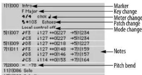
Figure 40-3: Examples of several different types of events displayed in the Event List.
Audio track Event Lists display audio events, including soundbites, volume automation control points and plug-in automation data.
![Audio volume Plug-in automation Soundbite 1[1]000 Intro F Major 4/4 click ↓ ▲ Volume 0.00 1[1]001 ▲ Volume -1.00 1[2]233 Insert A: Sonic Modulator [Low Pitch Depth] 0.470 1[2]293 Insert A: Sonic Modulator [Filter LFO] LFO 1 2[3]134 Insert A: Sonic Modulator [Low Pitch Depth] 0.106 2[5]175 ▲ Volume -9.50 2[4]124 Qtr Leads-3.37 ↔12|099 →5|4|224 4[1]174 ▲ Volume 0.00 4[1]039 Insert A: Sonic Modulator [Low Pitch Depth] 0.697 5[4]160 ▲ Volume -17.5 5[4]245 Qtr Leads-26.7 ↔12|234 →8|4|79 7[1]061 Insert A: Sonic Modulator [Low Pitch Depth] 0.242 7[4]024 ▲ Volume -2.00 8[4]439 Qtr Leads-3.29 ↔0|39 →8|4|79](/content/2026/05/834832/images/89a79729e902027c3b2d4ff9358d2483125fccc2e6847feabcc6b2ba977838b4.jpg)
Figure 40-4: Examples of several different types of events displayed in audio track Event Lists.
Choosing time formats
Event locations, durations and end times can be displayed in any combination of Digital Performer's various time formats. See "Time Formats window" on page 100.
Figure 40-5: Any combination of Digital Performer's several time formats can be displayed in the Event List. For notes and audio soundbites, the location, duration and end time of the note are displayed in the chosen time formats.
Showing/hiding durations, end times and sync points
The Time Formats window in the Setup menu ("Time Formats window" on page 100) lets you show (check) or hide (unchecked) note and soundbite durations and end times. In addition, you can show or hide soundbite sync points in the Events Lists of audio tracks. For details about sync points, see "Sync points" on page 399.
Showing/hiding types of data
Use the View Filter at the top of the event list (Figure 40-1 on page 437) to temporarily hide types of data you are not currently concerned with, such as streams of continuous controller data or pitch bend. You can also access these filter settings, plus many more, in the View Filter (View menu). See "The Event List View Filter" on page 330.
TYPES OF EVENTS
Event List data falls into four general categories:
■ MIDI data
■ Audio data
■ Mix automation data
■ Clips and Conductor Track data
Within each category, there are several types of events, each identified by a small icon. The following sections provide a brief explanation of each data type.
MIDI DATA
Notes
As shown in Figure 40-2 on page 438, a MIDI note event comprises a start time (location), a pitch, an on velocity, an off velocity, a duration and an end time. The pitch is expressed as a note name and an octave, e.g. C#4. C3 is middle C on a keyboard, although with some patches it might sound in another octave. In addition, there are preferences that allow you to globally specify middle C as C4 instead or to display notes by their MIDI note number (from 0-127). (See “Data Display” on page 81.) The spelling of the note name is determined by the key signature you choose. See chapter 60, “Change Key” (page 755).
5|1|000 ↓C3 ↓127 ↔0|250 →5|1|250
On velocity is a value that represents how hard a note is struck. The harder you strike a note, the faster you are pressing it down, hence the term "velocity". Off velocity is a value that represents the speed at which a note is released. Some instruments don't respond to off velocities, but many use this information to determine envelope
decay parameters or other effects. Values of on and off velocities range from zero to 127. You can omit on and off velocities from the Event List display by unchecking them in the View Filter (View menu).
Duration is the time between the attack and release of the note. It is displayed in quarter notes and ticks, e.g. 3|240. Note that this is different from measure time, displayed in measures, beats and ticks. A note must have a minimum duration of one tick (0|001).
End time is the location at which the note stops playing — where it cuts off. Like note attack times, the end time is displayed in whatever time formats you choose in the Time Formats window.
Pitch bend
A pitch bend event comprises a start time and a value. Pitch bend data causes the pitch of notes being played to change. When a stream of pitch bend data occurs, a smooth pitch change can be approximated. A value of zero signifies no bend, increasing values bend the pitch up, and decreasing values bend it down. Values are in the range -8192 to 8191.
1|1|366 -1152
There is no specific MIDI standard for how much of a bend specific pitch bend data causes: each instrument may be different. Also, some instruments do not respond to all 16,384 values; adjacent values may produce the same result.
Patch change
A patch change event has a start time and a patch change number. When an instrument receives a patch change, it changes to the patch specified by that number.
Patch changes are generally in the range 0 to 127. Some MIDI devices use the range 1 to 128. In such cases, the patch number displayed in Digital Performer may be one less than the number on the MIDI module. Digital Performer thus would display a zero when a 1 was sent, a 9 when a 10 was sent, etc.
Some MIDI instruments have more than 128 patches. Since MIDI only allows for 128 different patch values to be sent, there is no direct way to access patches above the 127th one. In this case, there is usually some way to set up banks (groups) of patches and switch banks via a “bank select” MIDI command. If this is the case, and the device’s patch lists support bank select messages, patch change messages for the device appear with the appropriate bank select number as shown below. The bank number automatically appears in tracks assigned to a device that supports them in its patch lists. If the track is assigned to a non-bank select device, no bank number is shown.

Figure 40-6: If a MIDI instrument supports bank select, the bank selection numbers (controller 0 and/or 32)
Song change
Song changes, also called song select, select songs (a collection of rhythmic patterns) on drum machines. They have a value range of zero to 127. Song changes have no channel number when sent over MIDI: all connected instruments receive them.
3|1|000 Song #18
1|2|000 ■#1 Acoustic Grand Piano
Mono key pressure
Also known as aftertouch or channel pressure, this is actually a special kind of controller. A mono key pressure event has a start time and a value between zero and 127. If you continue to press down a key after you play a note, mono key pressure information is sent. The harder you press, the higher the value. Mono key pressure can be used for such things as changing the timbre (tone quality) of a sound or controlling the amount and depth of vibrato.
4|1|000 ± 67
Mono key pressure data can be voluminous. If you aren't using mono key pressure information, it is best to use the Input Filter to filter it out while recording.
Poly key pressure
This is similar to mono key pressure except that each key can generate its own pressure information instead of one pressure level for the whole instrument. This allows for much more subtle and complicated effects using aftertouch. A poly key pressure event has a start time, a pitch and a value between zero and 127.
5|1|000 ±E63 :89
Controllers
A controller event has a start time, a controller number which identifies the device being used (on the MIDI input keyboard), and a value. Continuous controllers (such as wheels and sliders) are generally numbered in the range zero to 63. These have value ranges from zero to 127. Switch controllers (on/off types like a sustain pedal) are numbered from 64 to 93 and have values of either On or Off. Controllers from 93 to 127 are reserved for future definitions.
10|1|000 ▲#7 :102
Each MIDI device can interpret controller data differently. Thus, data from the same controller might be used differently on two different MIDI instruments. To determine how a controller behaves on a particular unit, consult the owner's manual, and see "Event List hints" on page 448.
System exclusive
System exclusive data can be used for a variety of purposes. Each musical instrument manufacturer defines special kinds of data that are particular to specific instruments: patch dumps, drum machine patterns, tuning information, sample data and so forth. System exclusive data begins with an ID code specifying the manufacturer followed by the actual data.
1|1|000 □ F0 02 10 21 20 12 00 F7
Digital Performer lets you view and edit system exclusive data in hexadecimal (base 16) notation. See chapter 54, "System Exclusive" (page 697) for more information.
Tune request
The tune request is used for analog synthesizers, prompting them to tune their oscillators. It has no value and does not have a channel number when sent over MIDI: all connected MIDI instruments will respond to it if applicable.
12|1|000 Tune request
Mode changes
MIDI modes are used to set synthesizers to respond to MIDI data in different ways. Not all synthesizers respond to all MIDI modes.

Omni mode
Omni mode has largely disappeared from today's instruments. Back in the early days of MIDI, it was a standard feature, intended for the benefit of new MIDI users who weren't ready to deal with the concept of separate MIDI channels. When Omni Mode is on, a synthesizer ignores the channel in channelized messages (Note On, Note Off, Program Change, etc.) If your MIDI instrument has an Omni mode switch, turn it off and leave it off.
Poly mode ("Mode 3")
This is the most common mode used in MIDI instruments today. In Poly mode, all notes received on a MIDI channel are played independently. The number of simultaneous notes is limited only by the instrument's polyphony (the maximum number of notes that it can play simultaneously).
Mono mode ("Mode 4")
In the MIDI specification, Mono mode was tailored for early MIDI instruments that were only capable of producing a single timbre at any given time. When in Mono mode, a synthesizer acts like a number of independent monophonic synthesizers responding on adjacent MIDI channels. (MIDI guitar players can appreciate the need for this). Today's MIDI instruments generally implement “Multi Mode” (see below), which is somewhat more flexible and which allows Mono mode to be approximated.
Multi mode (Omni off)
This mode is only briefly mentioned in the MIDI Specification. However, it is probably the most common mode used today, and it is the recommended mode for sequencing. In Multi mode, a synthesizer acts like a number of independent MIDI synthesizers operating on different basic channels. Each of these “virtual synthesizers” can be in Poly or Mono mode.
The implementation of Mono mode within Multi mode is generally limited. Check your MIDI instrument's documentation to see how it interprets the MIDI Mono Mode and Poly Mode messages. Chances are these messages simply select monophonic or polyphonic reception on the channel to which the message is addressed. In other words, the “virtual synthesizer” is limited to one mono mode channel.
In true Mono mode, control change messages received on the basic channel minus one (or channel 16 if the basic channel is 1) apply to all the channels that have been assigned to Mono mode. This allows controllers to be “global”, affecting all channels without having to be sent on all of the channels at the same time, which would take up an excessive amount of MIDI bandwidth. Unfortunately, for MIDI guitar players, modern synthesizers are rarely able to simulate this feature.
Local control
In a MIDI instrument, local control is either on or off. When local control is on, the instrument works normally: notes pressed on the keyboard are played by the synthesizer unit. When local control is off, the keyboard is disconnected from the synthesizer unit. The keyboard transmits MIDI data to its MIDI OUT port; the synthesizer only plays data received from its MIDI IN port. This allows you to use an instrument as a controller while simultaneously using its synthesizer unit to play something else.
All Notes Off
The all notes off message causes all notes that are currently sustaining to be shut off.
AUDIO DATA
Audio data is displayed in audio track Event Lists, including those for audio (disk) tracks, aux tracks and master faders (which hold mix automation data).
Soundbites
A Soundbite (region of audio) comprises a location, soundbite name, duration and end time. All times can be expressed in any of Digital Performer's various time formats. Click it to select the soundbite. Option/Alt-click it to change the name. Double-click the name to replace the soundbite with another. Command-double-click to edit in the Waveform Editor.
5|4|245 Gtr Leads ↔12|234 →8|4|479
The Event List gives you precise information about soundbites. It consists of a chronological list of all the soundbites in the track. It also displays audio pan and volume events, as well as plug-in automation data.
Soundbite location
Indicates the location at which the soundbite starts playing back. Double-click to edit.
Soundbite duration
Indicates the length of the soundbite. This cannot be edited in the Event List. To edit the length of a soundbite, drag its edges in the Sequence Editor or Waveform Editor.
Soundbite end time
Indicates the location at which the soundbite ends. Double-click to edit. Note that editing the end time will also change the location by the same amount. In other words, changing the end time does not change the length; instead, it moves the entire soundbite.
Soundbite name
Identifies the soundbite by name. Click it to select the soundbite. Option/Alt-click it to change the name. Double-click the name to replace the soundbite with another. Command-double-click to edit in the Waveform Editor.
Event List soundbites are “clones” of their original The most important thing to realize about soundbites in the Event List is that they are “clones” of their original soundbite in the Soundbites window. For further explanation, see “Soundbites in a track are ‘clones’ of the original” on page 335.
Inserting a soundbite in the Event List
Soundbites can be placed in an Event List in one of several ways:
■ by inserting from the Event List (see “Inserting data in the Event List” on page 445)
- by dragging and dropping it from the soundbites window, a clipping window, the computer desktop, etc. (see “Dragging soundbites into the Event List” on page 446).
Soundbite sync points
In the Event List, soundbite sync points are displayed to the right of the duration and end time information as shown below. Sync points can be edited in the Event List.
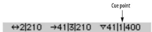
Figure 40-7: Sync Points in the Event List.
Soundbite layering
The Event List does not indicate soundbite layering. To see how overlapping soundbites are layered, view them in the Sequence Editor as explained in “Overlapping and layering soundbites” on page 393.
Audio volume and pan events
Audio volume and pan events represent the breakpoints that you see on the volume and pan automation lines displayed in the Sequence Editor. Audio volume and pan events can be identified by their name and continuous controller icon in the Event List:
| 2|3|173 ▲ Volume | -9.50 |
| 3|1|225 ▲ Pan | -22 |
Audio volume events
An audio volume event has a start time and a value (in dB). In the Sequence Editor, it is represented as a breakpoint on the volume line, where the line represents the volume ramp that is calculated between control points during playback.
Audio pan events
An audio pan event has a start time and a value in a range from -64 to +63. In the Sequence Editor, it is represented as a breakpoint on the pan curve.
For more information about controlling audio pan and volume, see chapter 70, "Mixing Board" (page 821).
MIX AUTOMATION DATA
Plug-in parameter automation
Audio plug-in automation events display their location, followed by the plug-in automation event icon, the insert on which the plug-in resides, the name of the plug-in, the parameter (displayed in brackets) and the value for the parameter. Below, the value is sine (sine wave) for the LFO type:
1|1|000 Insert A: AutoPan [LFO Type] | Sine
Mute automation
Mute automation events can appear in both MIDI and audio track event lists.
| 1|1|000 | [ MIDI Track Mute] | Enabled |
| 1|1|002 | [ Audio Track Mute] | Enabled |
Send level and mute automation
Audio track send levels and mutes can be automated, too.
| 1|1|005 | Send 3 [Send Level] | :-∞ |
| 1|1|010 | Send 4 [Send Mute] | :Enabled |
CLIPS AND CONDUCTOR TRACK DATA
Markers
Markers are displayed for reference in the edit windows for all tracks in a sequence. Since they are often used for reference during editing MIDI and audio data, they are not affected by edits made in the Event List (or other Editors) of normal MIDI and audio tracks. Instead, Markers can be edited in the Conductor track, the Markers window, the Sequence Editor and the Track Overview Time Ruler.
11|1|086 Solo
Meter changes
Meter changes are displayed for reference in the Editors for all tracks in a sequence. They can only be edited in the Conductor track editor windows. Meter change events display the time signature (the number of beats per measure, over the duration value which gets the beat) and the click value (the duration value between metronome clicks). See chapter 59, "Change Meter" (page 749) for more information.
2|1|000 6/8 click ♩.
Tempo changes
Tempo changes can be displayed and edited in the Editor windows for the Conductor track. Tempo change events display the duration value for the tempo marking, i.e. which value the tempo is measured in (quarter note = 90 for example), and the tempo value itself, which signifies the number of beats per minute. See chapter 58, “Change Tempo” (page 741) for more information.
1|1|183 ♩ = 99.14
Key changes
Key changes are displayed for reference in the Editor windows for all tracks in a sequence. They can only be edited in the Editor windows for the Conductor track. Key change events display the name of the key. See chapter 60, "Change Key" (page 755) for more information.
Eb Major
Clips
In the Event List, a clip event displays its duration and end time. These parameters can be edited in standard Event List fashion.
21|1|000 Clip - MIDI Bass 3 ↔ 32|000 → 29|1|000
Figure 40-8: A clip in the Event List.
INSERTING DATA IN THE EVENT LIST
The Insert button inserts an event of the type specified by the Insert menu. To insert an event:
1 Activate the Event List for the desired track by clicking on it.
2 Click on the Insert menu: a menu appears containing the different types of events you can insert.

Figure 40-9: Inserting events in the Event List.
3 Choose the type of event you wish to insert.
4 Press the Insert (+) button.
An event will pop up in front of the Event List.

5 Specify the time at which the event is to be inserted.
If you wish to change other values for the event, use the Tab or the Left Arrow and Right Arrow keys to move between the value fields.
6 To enter the event, press Return.
Inserting an event using the insertion cursor
If you click on the line between two events, you'll see a flashing insertion cursor. If you then insert an event (with the Insert button), its default location will match the event just below the insertion cursor. This is a convenient way to insert a new event at the same location as an existing event.
Inserting multiple events of the same type
If you will be inserting another event of the same kind, press the Enter key instead of Return (Mac) or the keypad Enter key (Windows). This will
insert the event and present you with another to be inserted. Press Command/Ctrl-period or the escape key to cancel the Insert.
When inserting Mode changes, or System Exclusive data, extra steps are required. See chapter 54, “System Exclusive” (page 697) for information on inserting this type of data. See chapter 60, “Change Key” (page 755) for information on inserting key changes.
EDITING DATA IN THE EVENT LIST
Commands in the Edit and Region menus work on events in Event Lists. This gives you the ability to precisely specify which events to modify. Using the Event List to edit events allows you to work with one track at a time.
Selecting data in the Event List
To edit events in an Event List, you must first select them, and then execute an edit or region command. For information on selecting events, see “Making an event selection in the Event List” on page 549. Selected events become highlighted to indicate that they are selected. Here are a few important things to remember when editing in the Event List.
■ Only highlighted events will be affected by the command. Also, events not visible due to the View Filter setting will not be affected.
- Use the View Filter at the top of the event list to display and edit only those events you wish to edit. This is a great way to hide data you are not concerned with at the moment — especially lengthy streams of controllers or pitch bend. For even more view filter control, see “The Event List View Filter” on page 330.
■ The Paste and Merge commands on the Edit menu work as follows: If one or more events are highlighted, the contents of the Clipboard are pasted at the time of the first highlighted event. If no events are highlighted, the contents of the
Clipboard are pasted at the location of the playback wiper (the main counter). See “Paste” on page 581.
- The Snip, Repeat, and Retrograde commands do not affect highlighted events. When using these commands, you must use create a time range selection that includes the events. See “Selecting a time range” on page 547.
■ Markers, key changes, meter changes, and tempo changes can be edited only in the Conductor track. They are not affected when highlighted or when you attempt to edit them directly in normal Event Lists. This allows you to select large regions of events without having to worry about excluding these events.
Choosing an insertion point for pasting
Click the line between two events to place a flashing insertion cursor there. If you then paste, the pasted material is placed at the same location as the event just below the insertion cursor.
Dragging soundbites into the Event List
You can insert soundbites into an Event List by dragging them from other windows, such as the Soundbites window, into the Event List. Just grab the move handle of the soundbite as show below and drop it on top of the open Event List. The soundbite is placed end-to-end with the last soundbite at the bottom of the list. You can also drag soundbites from a clipping window and the computer desktop.

Figure 40-10: Dragging and dropping Soundbites into the Event List from the Soundbites window: grab the move handle and drop it anywhere on top of the Event List.
Building a playlist
A playlist is a collection of regions played end-to-end to produce a continuous presentation of music. You can quickly build a playlist using the drag-and-drop technique shown in Figure 40-10 above. Just make sure that the soundbites you drop into the Event List have lengths that generate an even tempo when they are placed end to end. In the example above, notice in Figure 40-10 that the soundbite being used to build the playlist has a duration of exactly one measure so that the next soundbite used begins on a downbeat. You don't, of course, have to use one-measure lengths: just plan your durations accordingly when you are creating the soundbites you will use in the playlist.
Editing individual events
To edit any parameter field of an event in the Event List, hold down the Option/Alt key and click on the field. You can also double-click on the field. In most cases, a text box will appear surrounding that field in which you can enter the value you want; some events display a dialog box.
| F\#2 | 127 64 | ↔ 4|008 | |
| 27|1|019 | E2 | 77 64 | ↔ 3|464 |
| 28|1|001 | C3 | 114 64 | ↔ 0|225 |
| 28|1|238 | A2 | 111 64 | ↔ 3|289 |
| 29|1|019 | D3 | 120 64 | ↔ 3|356 |
| 29|4|354 | E3 | 84 64 | ↔ 0|138 |
| 30|1|020 | F\#3 | 77 64 | ↔ 3|413 |
| 30|1|022 | D3 | 72 64 | ↔ 3|408 |
Figure 40-11: Editing an event parameter.
After you begin to edit events by using text boxes, you can use the Tab, Enter, and arrow keys to move between fields and events.
Here is a list of the keys you can use when a text box is present:
■ Return enters the value and closes the text box — as does clicking anywhere outside the box.
■ Command/Ctrl-period or Escape cancels the entry.
■ The Enter and Down Arrow keys enter the value and highlight the same field in the next event.
■ The Up Arrow key enters the value and highlights same field in the previous event.
■ Tab and the Right and Left Arrow keys move through each field of an event.
Changing event values by dragging
When editing an event parameter as shown above in Figure 40-11, you can press on the popped-up number and then drag vertically to change it. Drag up to increase it; drag down to decrease.
Changing event values from a MIDI controller You can use your MIDI input keyboard to enter values for events. When a parameter is popped up for editing as shown in Figure 40-11, if you send an event over MIDI of the same type as the parameter, it will be entered into the field. For example, if the pitch field of a note event is popped
up for editing and you play a note on your MIDI controller, the pitch you play appears in the text box.
This technique is particularly useful when you are uncertain of a value. For example, you can set an on velocity for a note by double-clicking on the on velocity field so that it pops up, then hitting a key on your controller until the note velocity sounds correct. Each time you hit the key, the new velocity appears in the pop up box; when you hear the one you want, simply press the Return key to save the value in the Event List.
Changing the name of a soundbite
To change the name of a soundbite in an audio track Event List, Option/Alt-click the soundbite's name. When you change the name of a soundbite, you change the name for all instances of that soundbite.
Replacing a soundbite with another soundbite
You can replace a soundbite with another by double-clicking the soundbite name in the Event List. A list appears showing of all the soundbites in the project:

Double-click the desired soundbite. The new soundbite is placed in the same location as the original one.
EVENT LIST HINTS
You can use the Event List to find out useful information about the way your MIDI instruments output data. For example, you can use the Event List to determine the controller number for a wheel, slider, foot pedal, etc.:
1 Locate a controller event in an Event Edit window.
If you can't find one, insert one.
2 Option/Alt-click on the controller number field to make a text box appear.
3 Move the controller on your input keyboard.
The controller number will be displayed in the text box.
4 Press the Return key to save the event, or the Command and period keys to close the text box without making any changes.
Finding patch numbers
You can use a similar technique to find the patch numbers that correspond to each preset on a MIDI module. Make sure that the MIDI output from the device in question connects to the MIDI input of your interface; then:
1 Find a Patch Change event in an Event List.
If you can't find one, insert one.
2 Option/Alt-click on the patch number field to make a text box appear.
3 Select the preset or patch on the MIDI module.
The patch number box in Digital Performer will display the MIDI patch number corresponding to the preset.
4 Press the Return key to save the event, or the Command and period keys to close the text box without making any changes.
Inserting multiple events with Repeat
You can insert multiple events of the same type quickly by first inserting the event, selecting a time range including the event (in any graphic editor) and then choosing Repeat from the Edit menu. This will effectively duplicate the event the specified number of times. You can then go back and edit the locations and values of each event.
CHAPTER 41 Drum Editor
OVERVIEW
The Drum Editor window is an advanced, musical environment for creating and editing percussive music. The Drum Editor places notes in rows (by pitch) on a rhythmic grid, allowing you to quickly and intuitively view and edit rhythmic patterns. The columns in the grid can be adjusted to any rhythmic resolution you want, from 64th notes to whole notes, including triplet, dotted, and double-dotted variants. Rows in the grid represent percussion instruments (kick, snare, hat, tambourine, etc.). Each row (instrument) can be independently viewed in one of four different modes that display various degrees of information about the notes, from simple note-on/off cells, to velocity bars to duration views. Like other edit windows, the Drum Editor can display notes from multiple tracks at one time, allowing you to build drum kits with instruments from multiple synths, drum machines, samplers, etc. MIDI controller data is displayed below the drum grid, just like the graphic editor.
The Drum Editor includes advanced features like the Rhythm Brush, which lets you ‘paint’ drum parts (like triangle, bongo, etc.) that you don’t want to take the time to sequence yourself. The Drum Editor also allows you to easily work with advanced rhythmic patterns like triplets, fills, and odd meters such as 7/8 time.
Quick Reference....452
Tool palette quick reference 455
Drum Editor mini-menu 455
Drum Editor basics 456
Opening the Drum Editor 456
The Drum Editor title bar 456
The Track Selector....456
The Master Track Selector ....456
Using the Window Target menu....457
Snap, Cursor, Selection, and Event Information ..... 457
The four drum editor panes ....457
The note list....457
The note grid....463
The controller grid and median strip 467
Using the Tool palette in the Drum Editor....467
Note groups....470
Scrolling during playback....471
Scrubbing in the Drum Editor 471
Zooming....471
Graphic editing techniques ....471
QUICK REFERENCE

Figure 41-1: The Drum Editor provides a powerful environment for viewing and editing percussive music.

Blank row for adding new notes: Type in or play in a new pitch to add the note pitch (instrument). Use the drop-down menu (triangle) to show pitches that are currently hidden.
Continuous Data Grid: Displays continuous data on a time vs. value grid. Pitch bend, key pressure, controllers, and note velocities are displayed simultaneously on this grid. An event's location is measured by the Time Ruler at the top of the window. Value is determined by the Continuous Data Ruler on the left. Each type of continuous data has a unique icon. If the display mode is set to Lines mode, streams of controllers are represented as breakpoints on a line.
Continuous Data Ruler: Measures continuous data events. This ruler can be toggled between three scales: a controller scale from 0 to 127, whose origin rests at the bottom of the window; a pitch bend scale from -8192 to 8191, whose origin appears in the middle of the grid; and a combination scale that shows both pitch bend and controller data at once on a -80 to 127 scale. Toggle among the three scales by clicking on the ruler.
Display mode menu: Lets you choose one of four display modes for each row (instrument): grid, grid with velocity, velocity and duration, or 'Free' mode.
Grid Resolution menu: Determines the rhythmic duration of each column in the note grid for viewing and editing notes. Can be changed at any time to any duration in the menu, from a 64th note to a whole note, with triplet, dotted, and double-dotted variants.
Grid with velocity mode: One of four modes in which each row can be viewed (as chosen from the display mode menu to the left of the row). Grid with velocity mode uses the height of the bar to indicate the note's velocity.
Hot spot for row resizing: When displaying a row in any mode other than 'grid' mode, you can position the cursor above it's bottom edge (below its display mode menu) to change the cursor into a hand. You can then grab the bottom edge with the hand cursor and drag it vertically to resize the row.
Instrument/Tool settings: This area of the window displays settings for the currently selected note in the note list — or the Pencil tool or Rhythm Brush tool if either tool is selected. Use these settings to enter triplet figures or paint custom rhythms.
Marker strip: Displays markers, meter changes, and key changes. Also displays the Memory Cycle bar.
Master track button: This button is displayed next to the name of each track in the list. Only one track can be the master track when multiple tracks are present. The median strip and continuous controller grid only display master track data. Click the master track button to make a track the master track.
Median Strip: Displays discrete MIDI events such as patch changes, mode changes, switch controllers like #64 (sustain), and system exclusive events. Each type is displayed as an icon, defined by the Legend window. The Median Strip serves as a border between the Note Grid and the Continuous Data grid; it can be dragged up and down with the handle at its left to proportionally resize the grids.
Median Strip Move Handle: Moves the Median Strip up or down. Dragging up shrinks the Note Grid and enlarges the Continuous Data Grid; dragging down enlarges the Note Grid and shrinks the Continuous Data Grid. Double-click the move handle to collapse the bar all the way to the bottom of the window. Double-click it again to restore it to its original position.
Memory Cycle strip: Displays the Memory Cycle loop as a colored bar. Drag in the strip to enable the feature and set the start and end times. Drag the endpoints of the bar to change them, or drag the bar to move it. Click the bar to toggle Memory Cycle on or off.
Auto Record strip: Displays the Auto Record region. Click and/or drag in the Auto Record strip to enable the feature and set the punch-in and punch-out times. Drag the endpoints to change them, or drag the bar to move it.
MIDI track: The drum editor can display notes from multiple tracks, as determined by the track selector, which shows/hides tracks. The pitches for each track are displayed below the track. The track row itself displays the track's playback device and current patch (drum kit).
Note Grid: Displays notes on a time vs. pitch grid. Only notes are displayed on this grid. Pitch is determined by which row the note is in. Location and duration are measured by the Time Ruler above, with duration determined by the length of the bar (either vertically or horizontally, depending on the mode in which the row of notes is being viewed). Notes can be edited with the mouse one at a time, in a group, or by region.
Note grid scroll bar: Scrolls the note grid when the list is longer than the window size.
Note group: A set of pitches that act as a single instrument, such as several variations of a hit hat sound (pedal, open closed, etc.) A note group ensures that they won't be played at the same time; it also lets you mute/unmute them as a group.
Note list: Displays the list of MIDI note pitches you are working with in the drum editor. Each row represents one pitch (C3, Eb4, etc.), which corresponds to a particular drum instrument. Patch list: lets you choose the drum kit on your drum machine or synth for the track.
Playback location indicator: Shows Digital Performer's current playback location.
Pointer tool: Turns the cursor into Digital Performer's standard arrow cursor for selecting.
QuickFilter button: Temporarily hides all types of continuous data, except for the type that is currently selected.
Selected Note: When a note is selected, it highlights. If the note is being displayed with its duration, drag the end of the note to change its duration. Complete information about the selected note will automatically appear in the Event Information window, if open.
Selected volume controller: Continuous controllers, such as volume controllers, are edited in the same way as they are in the MIDI Editor.
Time ruler: Measures time in measures and beats (and ticks, at small grid resolutions) for the columns and data in the note grid, median strip and continuous data grid. The time ruler can be zoomed in or out using the Grid Resolution menu or the time zoom buttons in the bottom right corner of the window.
Track selector list: Shows and hides tracks in the Drum Editor.
Velocity and duration mode: One of four modes in which each row can be viewed (as chosen from the display mode menu to the left of the row). Velocity and duration mode uses the height and length of the note to indicate its velocity and duration, respectively.
TOOL PALETTE QUICK REFERENCE
Pointer: Use the pointer to select data, move data and lengthen or shorten notes (in Free mode).
Pencil: Use the Pencil tool to insert data.
Reshape: Use the Reshape tool to reshape note velocities in the note grid or controller data in the continuous data grid.
Pencil/Reshape Curve: Determines the shape of the continuous data that you modify with the Reshape tool.
Reshape mode: Determines what the Reshape tool does to continuous data: set it to a specific value, add to it, subtract from it, scale it or limit it.
Rhythm Brush: Turns the cursor into a brush that ‘paints’ in percussive note patterns in the note grid. You choose the desired pattern from the menu in the Brush tool settings area below the note list.
Zoom: Zooms the time ruler in. Option/Alt-click to zoom out.
Loop: Inserts a loop in the drum grid row just to the right of the track name.
Scrub: Scrubs MIDI data when you drag in the note grid. Only the tracks currently visible will scrub. To scrub all tracks, drag the playback wiper.
Velocity: Click on a note and drag up or down to adjust its velocity. Swipe horizontally in the continuous data grid to adjust multiple note velocities in a single gesture.
Hand: Allows you to scroll the note grid and continuous data grid smoothly and precisely, vertically and horizontally in a single gesture. Simply click anywhere in the grid and drag as desired.
DRUM EDITOR MINI-MENU
In addition to the standard items covered in “Edit Window mini-menus” on page 344, the Drum Editor mini-menu has the following additional items:
| Scroll to Counter Scroll to... |
| MIDI Edit Filter Selected Continuous Data ^Q Edit Window Preferences... MIDI Editing Preferences... Continuous Data Preferences... |
| Event List Sequence Editor Notation Editor QuickScribe Editor MIDI Editor |
| Show Pitches for All Notes ✓ Always Show All Notes Hide Selected Pitches Learn Pitches Make Group from Selection Remove Pitches from Group |
Figure 41-2: The Drum Editor mini-menu.
MIDI Edit: Allows data in the Drum Editor to be edited from a MIDI controller.
Filter Selected Continuous Data: This checkable menu item is linked to the Show only check box (Figure 39-1 on page 412) and performs the same function.
Edit Window Preferences: Opens the preferences for edit windows.
MIDI Editing Preferences: Opens the preferences for the MIDI Editor.
Continuous Data Preferences: Opens the preferences for the display of continuous data in MIDI Editors.
Show Pitches for All Notes: Displays all currently hidden notes in the note list.
Always Show All Notes: When checked, tracks will always display all notes (and their corresponding pitch) that currently exist in a track. This ensures that you always see every note (and all pitches being used) in the track. When unchecked, you need to manually add pitches when adding notes to the track.
Hide Selected Pitches: Temporarily removes the selected rows (pitches) from the note list. You can show them again by choosing them from the menu in the last row.
Learn Pitches: Prepares the Drum Editor to add pitches to the note list when you play them on your MIDI keyboard, drum pad, or other MIDI controller.
Make Group From Selection: Joins two or more selected pitches in the note list together into a note group. The most common example of when you would want to use a note group is a hi-hat group, which consists of several hi-hat sounds (closed, open, foot-closed, etc.) that should never sound at the same time and that are treated as one percussion instrument (for muting/unmuting, etc.)
Remove Pitches From Group: Separates a note from a note group.
DRUM EDITOR BASICS
The Drum Editor is very similar to the MIDI Editor in overall operation, except that it has several features that are specially designed for the graphic insertion, selecting and editing of percussive MIDI material. Other features, such as the Continuous Data Grid, operate identically to the MIDI Editor. As such, this chapter focuses on features that are unique to the Drum Editor.
OPENING THE DRUM EDITOR
See "Opening edit windows" on page 341.
THE DRUM EDITOR TITLE BAR
The Drum Editor title bar contains the standard edit window buttons discussed in “Window Target” on page 343 and “The Track Selector”, below.
THE TRACK SELECTOR
Like other Digital Performer editors, the Drum Editor has a track selector that lets you view multiple tracks at one time. (See “Viewing multiple tracks in one edit window” on page 342.) This allows you to build drum kits with sounds from several different MIDI instruments in your studio, as demonstrated below in Figure 41-3. For example, you could use the kick and snare from a software sampler, and cymbals, toms and percussion sounds from a drum machine.

Figure 41-3: The Drum Editor's track selector allows you to show/hide tracks. Click tracks in the track selector list to show/hide them.
THE MASTER TRACK SELECTOR
When the Drum Editor is displaying multiple tracks, the Master Track Selector button (Figure 35-9 on page 342) determines which track is chosen for single-track operations in the window. For example, the continuous data grid portion of the window only displays continuous data in the master track.
USING THE WINDOW TARGET MENU
Like other editors, the Drum Editor allows you to switch to other sequences by clicking its Window Target menu. See “Switching to a different sequence” on page 343.
SNAP, CURSOR, SELECTION, AND EVENT INFORMATION
The Snap, Cursor, Selection, Event Information windows (Studio menu) display information about the current cursor position, selection range, and selected event. These windows update as you work, providing constant feedback.
The Information Bar can also be displayed directly in the Drum Editor, showing some or all of the data shown in the Information windows.
For complete details about these information windows and the Information Bar, see chapter 37, "Information Windows" (page 355).
THE FOUR DRUM EDITOR PANES
As shown below in Figure 41-4, the Drum Editor window is divided into four panes, which are explained in the remainder of this chapter.

Figure 41-4: The four areas of the Drum Editor window.
THE NOTE LIST
Synthesizers and samplers typically supply drum sounds in 'kits'. A MIDI patch change message calls up a certain drum kit (Brush kit or Techno kit, for example), and then individual notes (pitches) trigger various percussion instruments within the kit, such as kick drum, snare, hi hat, tambourine, and so on. The kick drum might be triggered by playing C1 (two octaves below middle C), and a snare drum might typically be triggered by D1.
Each pitch represents a drum instrument
As you can see, each pitch (or row) represents a particular percussion instrument. Digital Performer's Drum Editor is based on this standard method organizing drum sounds in MIDI instruments. In essence, the note list (as shown in Figure 41-4) is a list of the percussion instruments you are working with. Each pitch (drum instrument) gets its own row, which displays the MIDI pitch (C1, Eb3, etc.) and name of the instrument, along with several other parameters for the instrument. (If the name of the instrument does not appear automatically, you can type it in. For details, see “Working with note names” on page 462.) Each row in the note list extends into the note grid to the right, which displays the actual MIDI notes (more on the note grid in a bit).

Figure 41-5: the note list.
Parent MIDI tracks
All notes in the Drum Editor are listed below their parent track, as demonstrated above in Figure 41-5. Parent tracks have the following settings, which are the same settings shown for the track in the Tracks window.
Move handle
Moves the track, together with all associated notes.
Record button
The track's record button arms the track for recording, overdub recording or Auto Record.
Play button
The track's play button mutes and unmutes all notes in the track together at one time.
Track name
This is the name of the track, just like in the Tracks window. Option/Alt-click it to change the name.
Playback device
Just to the right of the track name is the MIDI playback device and MIDI channel for the track. If no device is selected, you'll see dashes. Click on the playback device to open a menu of MIDI devices. This list of devices is supplied by your MIDI device configuration (Setup menu > Bundles > MIDI Devices tab).
Default patch/drum kit
At the far right of each Track row is the default patch (drum kit) that is currently selected for the track. If no drum kit is currently chosen, you'll see dashes. Click on this area of the row to choose a default patch or drum kit.
Parent track selecting/highlighting
Parent track names in the Drum Editor highlight when there is a selection in the track, just like in the other editors. Similarly, you can click (or Shift-click or Command/Ctrl-click) the track names in the Drum Editor to include the track in (or exclude it from) the current time range selection.
Working with the note list
As shown in Figure 41-5 on page 457, each note is displayed below its parent MIDI track. Here is a summary of the settings in each row for each note (instrument).
Move handle
Drag the move handle up or down to move the instrument in the list. You can't drag pitches above their parent track in the list or below the next track in the list.
You can also use the move handle to add one or more selected notes to an existing group. To do so, select the notes you want to add, and then Command/Ctrl-Option/Alt-drag one of their move handles and drop them into the group.
Play button
Mutes and unmutes the instrument (pitch), even if it resides in the same track as other MIDI pitches.
Pitch (instrument)
Displays the MIDI note for the row. To change the pitch (instrument), click on this box and drag up/down, or type in a new pitch, or play a new pitch from your MIDI controller. The MIDI notes in the grid will be transposed to the new pitch.
Name
Displays the name for the MIDI pitch as determined by the MIDI instrument and drum kit to which the parent track is currently assigned. A drum kit must be assigned to the parent track for note names to appear. If Digital Performer doesn't know the factory-supplied names for the device, and if you haven't typed in a name yet, the MIDI pitch is displayed here instead (e.g. 'C3'). If it does not allow you to type in a note name, you need to choose a patch for the note's parent device (in the Patch column). For further details, see "Working with note names" on page 462.
Click the pitch name to select the instrument row.
Double-click the pitch name to select all notes of that pitch in the track.
The name column also displays a menu for changing notes as shown below in Figure 41-6. This menu is only active if the parent MIDI device and patch has note names. If so, you can use this menu to switch the row to a different instrument.

Figure 41-6: Changing an instrument with the note menu.
Quantize
This column displays whether the instrument is being quantized (Q), Groove Quantized (G), or Humanized (H). All three forms of processing are applied non-destructively in real time during playback; they do not modify the actual data in the track. If no processing is being applied, this column displays a dash (-). The Quantize options appear in the area below the note list as explained below in the next section.
To apply any of these forms of quantizing, choose the desired effect from the menu provided in the Quantize column.
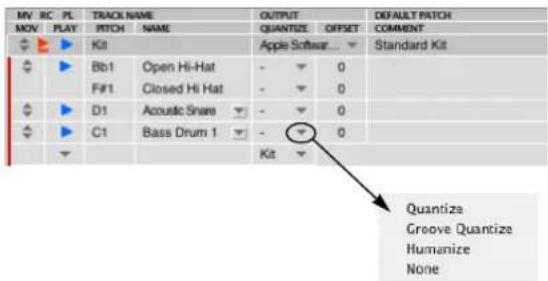
Figure 41-7: Click the triangle in the Quantize column to choose non-destructive, real-time a quantize effect.
Adjusting quantize settings
To adjust the quantize settings for an instrument:
1 Click the instrument name to select it.
The quantize menu appears in the instrument settings area below the note list as shown in Figure 41-8.
2 To get a better view of the quantize settings area of the window, click the expand button shown below and drag the resize handle upwards as needed. When you're done with the settings, click the expand button again to shrink the settings section back to its original, smaller size (for better viewing of the note list).

Figure 41-8: Use the expand button on the left of the divider bar and the resize handle on the right as shown here to get a complete view of the quantize settings. When you're done, click the resize button again to snap the divider bar back to its original position.
3 Choose quantize settings as desired. They work the same way as Digital Performer's quantize, groove quantize, and humanize plug-ins for MIDI tracks. You can change the settings at any time.
Offset
This is the instrument's timing offset in ticks. Negative values shift the instrument earlier in time. Positive offsets shift it later.
Comment
Type in a comment of any length for the instrument.
Viewing only the notes you're working with
Typically, drum kits provide dozens of instruments mapped across three or four octaves. But one of the best things about Digital Performer's Drum Editor is that it lets you view only the notes you wish to work with. So you'll always see a clear, compact list of drum sounds that you're actually using, without a long list of other sounds getting in the way. When you first open the Drum Editor window for a track, it will display one row for every note (pitch) that already exists in the track. You can also add pitches (instruments) to the list at any time.
Always Show All Notes
In the Drum Editor mini-menu, there is a checkable command called Always Show All Notes. When checked, tracks will always display all notes (and their corresponding pitch) that currently exist in a track. This ensures that you always see every note (and all pitches being used) in the track. When unchecked, you need to manually add pitches when adding notes to the track.
Adding instruments to the list
If the Always Show All Notes option explained above is unchecked, there are several ways to add instruments (pitches) to the list using the mouse and computer keyboard (discussed below). You can also add instruments by simply playing them on your MIDI keyboard, drum pad, or other MIDI controller (see “Adding instruments from your controller” on page 461).
Adding notes to the list using the 'blank' note At the end of the note list for each track in the Drum Editor is a 'blank' note, as shown below.
| MV | RC | PL | TRACK NAME | OUTPUT | DEFAULT PATCH | |||
| MOV | PLAY | PITCH | NAME | QUANTIZE | OFFSET | COMMENT | ||
| Kit | Apple Software... | Standard Kit | ||||||
| Bbl1 | Open Hi-Hat | - | ✓ | 0 | ||||
| F#1 | Closed Hi Hat | - | ✓ | 0 | ||||
| D1 | Acoustic Snare | - | ✓ | 0 | ||||
| C1 | Bass Drum 1 | - | ✓ | 0 | ||||
| Kit | ✓ | |||||||
Figure 41-9: use the 'blank' note at the bottom of each track to add instruments to the list.
There are several ways to add a pitch (instrument) using this blank note.
If the track has note names (it's assigned to a MIDI device for which there are note names), you can choose the instrument by name from the note
name menu as shown below in Figure 41-10. You can also use this menu to show notes that have been hidden (explained later).

natural_image
Simple graphic with a downward arrow inside a circle and a red vertical bar on the left (no text or symbols)Figure 41-10: Use the menu in the blank note to add new notes or show notes that have been hidden.
Or you can click in the name column and start typing the desired name. When you press the return key, it matches to the closest available name.

If note names are not available, you can type in the desired MIDI note in the pitch text box as shown below. (You can also type in the pitch in the name column, and the pitch column will be filled in automatically when you press the return key.) If you want to choose the pitch by playing on your MIDI keyboard, drum pad, or other controller, simply click on the pitch text box and play notes on your controller until you hear the drum instrument you want. Its corresponding pitch will appear in the text field as you play. Press the return key to confirm your choice.

If you're not sure what the correct pitch is for the drum instrument you want, do the following:
1 Make sure that the Audible mode button in the Control Panel is turned on. This allows you to audition the correct drum sound before you add it. 2 Click on the pitch box of the blank note and drag up or down until you hear the drum instrument you want.
3 Press the return key to confirm your choice.
Adding instruments from your controller You can quickly add notes from your MIDI keyboard, drum pad or other MIDI controller using the Learn Pitches mini-menu command:
1 Make sure that you've successfully achieved MIDI patch thru from your controller to the MIDI instrument and drum kit patch you'll be adding sounds from. You should be able to 'play' the desired drum kit from your controller. You can do this in the Tracks window by record enabling the track and choosing the desired patch.
2 Bring the Drum Editor window to the front and choose Learn Pitches from the Drum Editor window mini-menu.
3 One at a time, play each desired note from your controller. As soon as you play the note it will appear in the list.
4 To confirm your last added note and turn off Learn Pitches mode, you can choose one of the following actions: click the mouse, press the return key, press escape or press Command/Ctrl-period (.).
Adding a pitch range The empty note menu (Figure 41-9 on page 460) has an item called Add Pitch Range. This option lets you add a range of pitches in the track in one convenient operation.
Drum Editor drum kit presets
For your convenience, the Drum Editor provides drum kit presets, which are simply collections of MIDI pitches that correspond to common drum kits. Choose a preset drum kit from the Kit menu
at the bottom row of each track. Doing so replaces any currently visible pitches for that track with the preset kit pitches.
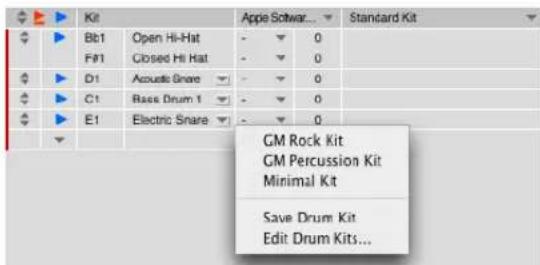
Figure 41-11: The drum kit presets menu in the Drum Editor.
Saving, renaming and deleting drum kits
To save the current pitches shown in a track as a drum kit preset, choose Save Drum Kit from the Kit menu (Figure 41-11). To rename or delete a kit preset, choose Edit Drum Kits from the Kit menu.
Hiding notes
To hide one or more notes (instrument rows) in the note list, click their names to highlight them and choose Hide Selected Pitches from the mini-menu. As a shortcut, press the delete key.
Showing notes that are currently hidden
If you're ever in a situation where you've got some existing notes in a track that are not currently being displayed in the Drum Editor, and you'd like to see them there, choose the note from the blank note menu as shown earlier in Figure 41-10 on page 461. To show all currently hidden notes, choose Show Pitches for All Notes from the mini-menu.
Working with note names
The Drum Editor is easiest to use when you can see the actual names of each drum instrument in the note list. Note names are only displayed for tracks that have been assigned to a drum kit on one of your MIDI instruments.
If Digital Performer already ‘knows’ the factory default note names for the instrument, the name of each drum automatically appears in the note list. If not, you can type in the name by hand.
Editing note names in the Drum Editor note list also modifies their name in the list Digital Performer, so the change will be reflected across all your Digital Performer projects.
If the track isn't assigned to a drum kit (patch), the instruments in the Drum Editor note list are listed by their MIDI pitch only, and you cannot type in names for them.
If the track is assigned to a MIDI device group, the Drum Editor window allows you to type in names for each pitch. For information about MIDI device groups, see “Creating a MIDI device group” on page 142.
You can assign a drum kit to the track either in the Tracks window (as usual) or in the Drum Editor itself:
1 In either the Tracks Window or the Drum Editor (as shown below in Figure 41-12), assign the track to a MIDI instrument and MIDI channel that provides drum kits (usually channel 10).
2 Choose the desired drum kit for the track.

Figure 41-12: Assigning a track to a drum kit in the Drum Editor.
3 Check for the instrument names in the list.

Figure 41-13: Instrument names in the note list.
4 If drum instrument names don't appear, Option/Alt-click the pitch in the Name column to type in the name by hand.
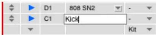
Figure 41-14: Typing in note names by hand.
Working with factory-supplied note name lists
Note names are supplied by Digital Performer. When you type in a note name in the Drum Editor, it actually gets stored by Digital Performer, which associates the name with a particular drum kit (patch change event) and MIDI instrument (device) in your your MIDI device configuration (Setup menu > Bundles > MIDI Devices tab). Digital Performer provides factory supplied note names for some drum machines, synthesizers and sound modules. There may be times, however, when you need to create your own note name list for a device that isn't yet supported. Or you may have customized the drum kit and need to customize its associated note name list. The Drum Editor environment is much easier to work with when note names are present.
Working with pitched percussion
Some drum kits contain a pitched percussion instrument, like a tom sound or a single snare sound, that has been mapped across several pitches. Sometimes, an entire drum kit will be devoted to such a thing. The Drum Editor has several powerful features that let you work with pitched percussion of this kind as well. In a case like this, you can treat each note separately as usual, or you can use the Drum Editor's grouping feature to treat several pitches as one instrument.
THE NOTE GRID
The note grid displays the MIDI note data for each drum instrument row. Each cell represents a beat on the grid. The resolution (duration) of the cells can be changed globally at any time using the View Resolution menu above the note list.

Figure 41-15: The View Resolution menu controls the note grid.
Alternatively, you can change the View Resolution by changing the edit resolution in the Snap Information window. Note that when the Drum Editor has the focus, the Snap Information window's "Snap to Grid" setting cannot be disabled.
View resolution
The view resolution menu lets you choose how much time is represented by the cells (columns) in the note grid. To be musical, the choices are
expressed in note durations, from a 64th note up to a whole note. You can choose any resolution you want and change it at any time. For example, you might normally work with a 16th note grid, but you might want to switch to a 32nd note grid to insert a roll of some kind. The longer grid durations (quarter, half and whole note) give you more of a 'birds-eye' view of the data. You can also set the grid duration to triplet, dotted, or double-dotted versions of each note.
The time ruler
The Drum Editor time ruler functions in much the same way as the time ruler in Digital Performer's other windows. However, there are a few minor differences. First of all, it displays only one of Digital Performer's four time formats: measures. This is because the nature of the Drum Editor grid is musical; it wouldn't make that much sense, for example, to build a drum groove based on SMPTE frames.
The other difference is, of course, its appearance. The Drum Editor time ruler looks a little different, but it is essentially the same as all other time rulers. For example, you can drag in it to select time ranges, as usual.

Figure 41-16: Making a time range selection in the ruler.
The marker strip
The marker strip is the area just below the time ruler. It displays markers, key changes and meter changes. These items cannot be edited here (moved, added, deleted), but you can click on markers to quickly select everything between the marker you click and the next marker. To edit them, use the Conductor track.
The Memory Cycle strip
The Memory Cycle Strip (Figure 41-1 on page 452) displays the Memory Cycle loop as a colored bar. Drag in the strip to enable Memory Cycle and set the start and end times. Drag the endpoints of the bar to change them, or drag the bar to move it. Click the bar to toggle Memory Cycle on or off. Also see “The Memory Cycle button” on page 207 and “Link Playback to Memory” on page 209.
The Auto Record strip
The Auto Record strip (Figure 41-1 on page 452) displays the Auto Record punch-in/out region as a colored bar, which works in the same fashion as described for the Memory Cycle bar above. Also see “Auto-Record” on page 210.
The playback locator
The row of lights below the marker strip indicates Digital Performer's current playback location, which illuminates the green light at the top of the column and highlights the rest of the column below. Click anywhere in the row of lights to instantly cue Digital Performer to that location.
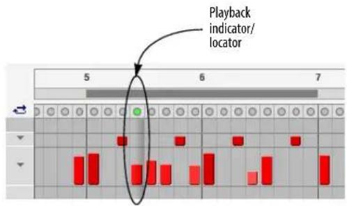
Figure 41-17: Playback locator. Click anywhere on the row of lights to instantly locate there.
The four display modes
Each row in the note grid can be independently viewed in one of four display modes as shown below:

Figure 41-18: The four display modes for each row in the note grid.
You can freely choose any one of the four modes for each row. For example, you might use Grid mode for the kick and snare, but Grid with Velocity mode for the hi-hat so that you can easily see the velocity (accent) contour of the hi hat part. You might use Free mode for a triplet, tuplet, fill or roll.
Display mode selection shortcuts
To set all rows to the same display mode, hold down the Option/Alt key while choosing the desired mode as shown in Figure 41-18. To set all currently selected rows to the same display mode, hold Command and Option while choosing the desired mode as shown in Figure 41-18.
Grid
In Grid mode (Figure 41-18), each cell in the row is a simple on/off toggle. Either the note exists or it doesn't. Notes appear as squares inside each cell, just like an old drum machine. Everything is visually quantized to the current grid setting (even if the actual data itself is unquantized). Notes that are inserted in grid mode will be quantized to the grid.
The only other information presented in this mode is the velocity shading of the note (if the velocity shading mini-menu option is checked). The note will be darker and more colorful if it has a high velocity; it will be lighter and less saturated if its velocity is low.
In Grid mode, notes are visually quantized to the grid, but their actual location (when recorded) might not be exactly quantized.
Grid with Velocity
Grid with Velocity mode displays notes as bar-graph-like columns, where the height of the note shows its note-on velocity. Like Grid mode, everything is visually quantized to the current grid setting.
Velocity shading will affect the color of each note bar. (If the bar is tall, the color will be more saturated to indicate a higher velocity).
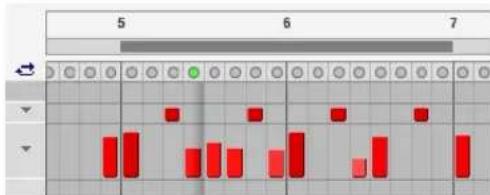
Figure 41-19: Grid with velocity mode.
Notes inserted in this mode will be quantized to the grid, but you may drag vertically within each grid cell to set the velocity. When inserting a series of notes, you can hold the Shift key to constrain the velocity. You can hold shift and let go as many times as you want while inserting a series of notes.
Velocity and Duration
Velocity and Duration mode displays three things: the note, its velocity and its duration. The height of the note indicates its velocity, and the length of the note bar shows its duration. Like the previous two display modes, everything is visually quantized to the current grid setting.

Figure 41-20: Velocity and Duration mode.
Notes inserted in this mode will have their start time quantized to the grid, but you can draw the duration freely within each grid cell. When you reach the boundary of the next grid cell, a new note is inserted; holding the Option/Alt key overrides this and creates one long note, spanning multiple grid cells.
As with Grid with Velocity mode, you can also drag vertically within each grid cell to set the note's velocity.
Free
Free mode is just like Velocity and Duration mode, except that notes are not visually quantized to the grid. Free mode is just like a miniature piano roll display for that one row in the Drum Editor. If you compare Figure 41-20 with Figure 41-21 below, you can see the difference between the two modes: in Figure 41-21, the notes are not visually quantized to the grid. Free mode is great for working with triplets, fills, and other rhythmically complex material.

Figure 41-21: Free mode.
Notes inserted in this mode will have their start time quantized to the grid, unless you hold the Command/Ctrl key; this overrides the grid and allows you to enter the start time freely. The duration of the note is determined by the Pencil tool's Default Duration (see "The Pencil settings" on page 467).
Like Velocity and Duration mode, when you reach the next grid cell a new note is inserted; holding the Option/Alt key overrides this and creates one long note, spanning multiple grid cells.
Resizing each row
In all display modes except Grid, you can vertically resize the row to any height you prefer. Just drag the bottom edge of the row, just below the display mode menu as shown below.

bar
| Time Point | Red Bar Value | | :--- | :--- | | 1 | 3 | | 2 | 4 | | 3 | 2 | | 4 | 3 | | 5 | 2 | | 6 | 4 | | 7 | 1 |Drag here with the hand cursor.
Figure 41-22: Resize the row to any height you prefer. Larger vertical sizing gives you more precision when editing velocities. Shorter vertical sizing allows you to see more rows at one time in the window.
Resizing shortcuts
To resize all resizable rows at the same time, hold down the Option/Alt key while resizing one of them.
To snap to fixed sizes when resizing, hold down the Command/Ctrl key. You can combine the Command/Ctrl key with the Option/Alt key as described above.
Working with triplets, tuples and non-grid based rhythms
To insert a triplet in the Drum Editor note grid, change the View Resolution to the triplet resolution desired.
Also, you can choose Free mode for the instrument line in which you wish to insert the triplet or tuplet, then choose the Pencil tool. Go to the pencil settings panel below the note list in the Drum Editor. Set the pencil settings to triplet/tuplet insertion by choosing, for example, 3 in the time of 4, or any tuplet combination that you like. Make the other settings as desired. Then drag the Pencil tool in the instrument line to the left or right.
The controller grid and the median strip work identically to the MIDI Editor. See “The Continuous Data Grid” on page 422 and “The Median Strip” on page 431.
Working with multiple tracks
If you are working with multiple tracks in the Drum Editor, the median strip and controller grid only show data for the master track (see “Master track selector” on page 343).
Inserting notes and continuous data with the Pencil tool
See "Pencil tool" on page 350 for details.
USING THE TOOL PALETTE IN THE DRUM EDITOR
The Tool palette provides essential cursor modes for inserting, selecting and editing data in the Drum Editor. For complete information, see chapter 36, “Tools” (page 347). The following sections cover Tool palette features that are unique to the Drum Editor.
The Pencil settings
When you click the Pencil tool, the pencil settings appear in the tool settings section of the Drum Editor window below the note list, as shown in Figure 41-23.
The pencil settings determine what type of MIDI data the pencil inserts. For notes, you can specify a duration and velocity, and you can even choose quantize settings for inserting in the Free display mode. The Tuplet option allows you to insert triplets, tuples, fills, rolls and other rhythmic figures (in Free mode), regardless of the current display resolution in grid mode.
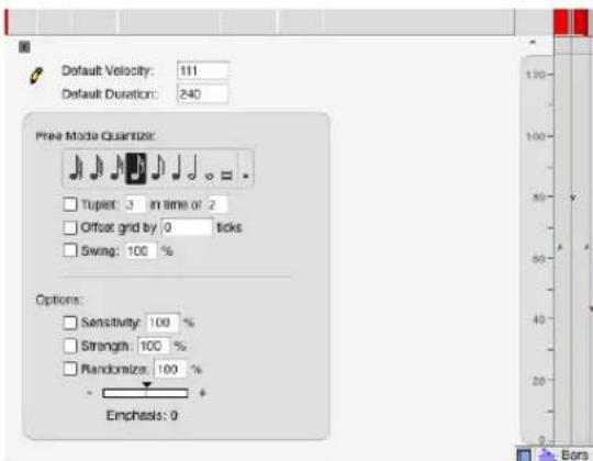
Figure 41-23: The pencil settings. To get a better view of all the pencil settings, resize the settings pane as shown in Figure 41-8 on page 460.
The Reshape tool

In the Drum Editor note grid, the reshape tool lets you edit the velocities of notes on the note grid when you are displaying
them in one of the view modes that shows velocity, such as the Grid with Velocity or Velocity and Duration modes. To modify the velocity of a single note, click on it. To modify several notes, you can drag across them.
In the Drum Editor continuous data grid, the Reshape Tool can be used to reshape streams of continuous data as explained in “The Continuous Data Grid” on page 422.
The Rhythm Brush tool

The Rhythm Brush lets you quickly 'paint' in drum parts in a wide variety of percussion instrument styles. For
example, if you're in the heat of building a groove, and you need a triangle part, but you don't want to take the time to play it in or program it by hand, you can choose a triangle pattern from the
Rhythm Brush preset menu and simply sweep the Brush across the triangle row in the note grid. The brush inserts notes in the preset pattern you chose. You can either use the pattern as is or modify it as desired.
The preset menu gives you many common percussion instrument styles, and you can tweak them as much as you like. You can even save your own Rhythm Brush presets.
You can also insert notes according to a standard rhythmic grid that you specify.
Using the Rhythm Brush
To insert notes with the Rhythm Brush:
1 If the instrument hasn't already been added to the note list, add it now. (See "Adding instruments to the list" on page 460 for details.)
2 Click the Rhythm Brush tool to select it.
The Rhythm Brush settings appear in the area below the note list as shown below.

Figure 41-24: The Rhythm Brush settings. To get a better view of all the settings, resize the panel as explained in Figure 41-8 on page 460.
3 Make the Rhythm Brush settings as desired (explained in the next section).
4 Drag across the desired portion of the note grid with the Rhythm Brush tool.
Choosing a rhythmic pattern for the Rhythm Brush There are five ways to choose a rhythmic pattern for the Rhythm Brush tool, as summarized below:
Method What to do
| To use the same pattern you used last time for an instrument | Choose the Use last preset used with the instrument option. |
| To use a new pattern that consists of a standard rhythmic grid | Click the Choose Preset option, and then set the grid as desired with the settings shown in Figure 41-24. |
| To use a standard rhythmic grid that you have previously saved as a preset | Choose the preset from the Preset menu. |
| To use a custom preset rhythmic pattern (triangle, bongo, etc.) | Click the Custom button, and choose the Rhythmic pattern from the menu, as shown below in Figure 41-25. |
To use a rhythmic pattern based Click the Fixed Value button and on a raw number of ticks between type in the desired number of each note ticks as shown in Figure 41-26.
The preset menu
The preset menu lets you save and recall standard grid pattern settings that you've made with the Grid settings shown earlier in Figure 41-24. To make a preset, make the settings as desired and then choose Save Pattern from the preset menu. A dialog asks you for a name, and then you click OK. Your new preset then appears in the Preset menu. To edit the presets in the menu, use the Edit Patterns item in the menu.
Using custom rhythmic patterns
The Rhythm Brush Custom option lets you select preset rhythm patterns and create your own preset patterns.

Figure 41-25: Click the 'Custom' button to create and select custom instrument patterns.
To choose an existing pattern, select it from the menu provided.
Creating custom patterns
To create and save your own preset pattern:
1 Select some MIDI note data in the Drum Editor Note Grid that matches the rhythmic pattern you want.
You can select any data you want, including data you recorded, data you imported into the Drum Editor from a library of drum patterns, or any other MIDI data. The data you select can be of any length.
If the rhythmic pattern you are creating either begins or ends with a rest (any period of silence), be sure to make a time range selection (instead of an event selection) that includes the necessary amount of time before the first note and/or after the last note. Otherwise, the saved pattern won't include the rest. Note, however, that a time range selection might include drum instruments that you may not want to include in your pattern. If this is the case, then make an event selection of the notes instead (using the Arrow tool) and set up the memory cycle points to the desired start and end times for the pattern. Later in this procedure, you will choose an option that uses the memory cycle points to determine the length of the pattern.
2 Choose the Rhythm Brush tool.
3 Click the Custom button.
4 Type in a name for the pattern in the text box provided (Figure 41-25).
5 If you want the pattern to inherit the velocities of the notes you have selected, check the Use Learned Velocity option. Otherwise, the pattern will be inserted with the velocities you draw with the mouse.
6 If you want the pattern to inherit the durations of the notes you have selected, check the Use Learned Duration option. Otherwise, the pattern will be inserted with durations determined by the current grid.
7 If you are using the Memory Cycle points to specify the start and end time of the pattern, check the Use Memory As Pattern Endpoints option.
8 Click the Learn button.
Deleting patterns
To delete a pattern, choose it from the menu and the click the Delete button.
Using a fixed value
The Rhythm Brush Fixed Value option lets you select any number of ticks between each note to be inserted as shown below in Figure 41-26.

Figure 41-26: Click the 'Fixed Value' option to specify a fixed number of ticks between each note.
The 'Use Alternating strokes' option
When generating evenly spaced notes with the Grid or Fixed Value options (Figure 41-24 on page 468 and Figure 41-26 above), use this option to insert them with alternative velocities (loudness). This effect creates a more realistic feel. One note will be loud and the next note will be soft. The alternating strokes percentage determines how much of a difference in loudness there is between the loud and soft notes. To use this option, choose a view resolution that is greater than the rhythmic division you want to insert. For example, if you want to insert a sixteenth-note high hat part with alternating strokes, set the View Resolution to an eighth note or quarter note. Choose a sixteenth note grid and then the alternating notes will be inserted into each column in the note grid as shown below in Figure 41-27. You can best see the alternating strokes effect in the 'Free' display mode.

Figure 41-27: To insert alternating strokes, choose a view resolution that is longer in duration than the notes you want to insert.
Loop tool

The Loop tool lets you graphically insert a loop in a track by dragging in the note grid in the same row as the track name, as shown below.
Figure 41-28: Inserting a loop with the Loop tool in the track row.
NOTE GROUPS
A note group can be made by selecting two or more pitches (instruments) in the note list and choosing Make Group from Selection from the Drum Editor mini-menu.

Figure 41-29: A note group.
Grouped notes function together as one instrument. Perhaps the most common way to use this feature is to make a hi-hat group out of several hi-hat sounds (closed hat, open hat, pedal hat, etc.) When notes (instruments) are grouped, the Drum Editor automatically constrains note insertion and editing so that you won't stack mutually exclusive drum sounds, such as an open hi-hat and a closed hi-hat, at the same time in the note grid. In addition, you can move the notes together with their single handle. Note, however, that they can still be individually offset or quantized.
Note groups are stored with their respective note names by Digital Performer.
Adding notes to a group
You can add one or more notes to an existing group by doing the following:
1 Select the notes you want to add.
2 Command/Ctrl-option drag one of their move handles and drop them into the group.
SCROLLING DURING PLAYBACK
The Auto Scroll command (View menu > Scroll) controls how the Drum Editor scrolls during playback. For example, the playback location indicator can travel across the window, or the window can scroll beneath a stationary playback indicator that remains anchored in the middle of the window. See “Auto scroll” on page 226.
SCRUBBING IN THE DRUM EDITOR
There are two ways to scrub in the Drum Editor:
- With the playback indicator — scrubs all play-enabled MIDI tracks. For more information, see “The playback locator” on page 464 and “Scrubbing multiple MIDI tracks” on page 229.
- With the Scrub tool (Figure 41-1 on page 452) — when you drag horizontally in the note grid, you'll hear only the tracks currently shown (with the Track Selector). See “Scrub tool” on page 352.
ZOOMING
The note grid and continuous data grid in the Drum Editor can be zoomed similarly to the MIDI Editor, including all zooming shortcuts. See “Zooming” on page 331 and “Zoom menu shortcuts” on page 332.
GRAPHIC EDITING TECHNIQUES
All of Digital Performer's powerful graphic editing features are available in the Drum Editor. See "Graphic editing techniques" on page 334.
CHAPTER 42 Notation Editor
OVERVIEW
The Notation Editor is one of several edit windows in Digital Performer. To learn more about editors in general, see chapter 35, “Edit Windows” (page 339).
Each MIDI track in a Digital Performer sequence can be viewed with the Notation Editor. The Notation Editor displays notes in a track on a continuously scrolling piano grand staff. In all other respects, the Notation Editor is very similar to the MIDI Editor. This chapter covers features unique to the Notation Editor. For additional information, review chapter 39, “MIDI Editor” (page 411).
If you would like to see two or more tracks in the same window displayed as music notation, use QuickScribe Editor as described in chapter 43, "QuickScribe Editor" (page 479).
Notation Editor Quick Reference ....474
Notation Editor Mini-menu....475
Opening the Notation Editor....475
The Notation Editor title bar....475
Snap, Cursor, Selection, and Event Information ..... 475
Notation Editor basics 475
Display resolution....475
Octave up/down buttons....476
Inserting, selecting & editing notes....476
Scrubbing in the Notation Editor 477
Zooming in the Notation Editor 478
Graphic editing techniques 478
NOTATION EDITOR QUICK REFERENCE
Selected note: Click once to select the note. While the note is selected, its information will appear in the Information Box above. Shift-click or drag a selection box to select more than one. Drag the note up or down to change pitch; drag left or right to change time location.
Grand staff: Displays notes on standard treble and bass clef staves. By default, middle C between the staves is C3. Click the Octave Up/Down buttons to change middle C to a different octave to place notes in higher or lower octaves on the staff.
Time zoom buttons: Contract or expand the Time Ruler, Grand Staff, and Continuous Data Grid to display more or less measures at a time. The left button zooms out (more measures), and the right button zooms in closer (less measures). Octave up/down buttons: Transpose the display of notes on the Grand Staff by octaves. When untransposed, middle C on the Grand Staff is C3. For example, in a bass track, low notes are displayed many ledger lines below the staff. To distinguish the pitches, click the Octave Down button; middle C will become C2 and the bass notes will be displayed an octave higher on the grand staff. An octave indicator appears in the Staff Margin to indicate the degree of transposition.
Staff margin: A portion of the Grand Staff that displays clefs, key signature, and meter. The margin remains fixed at the edge of the window and does not scroll along with the notes.
Continuous data grid: Displays continuous data in the same manner as the MIDI Editor.

Figure 42-1: The Notation Editor.
NOTATION EDITOR MINI-MENU
The Notation Editor mini-menu has the same items as the MIDI Editor. For details, see “MIDI Editor mini-menu” on page 415.
NOTATION EDITOR BASICS
The Notation Window is similar to the MIDI Editor. It has a Time Ruler, a Markers Strip, a Median Strip, and a Continuous Data Grid, features that are identical to those found in the MIDI Editor. Instead of a pitch ruler and note grid, however, the Notation Editor displays notes on a grand staff in standard music notation. Octave Up/Down buttons are provided to center any octave on the grand staff, and a non-scrolling staff margin on the left displays clefs, key signature, and meter.
For further information about the Time Ruler, Markers Strip, Median Strip, and Continuous Data grid, refer to chapter 39, “MIDI Editor” (page 411). Features that are unique to the Notation Editor are discussed below.
OPENING THE NOTATION EDITOR
See "Opening edit windows" on page 341.
THE NOTATION EDITOR TITLE BAR
The Notation Editor title bar contains the standard title bar items discussed in “Window Target” on page 343.
SNAP, CURSOR, SELECTION, AND EVENT INFORMATION
The Snap, Cursor, Selection, Event Information windows (Studio menu) display information about the current cursor position, selection range, and selected event. These windows update as you work, providing constant feedback.
The Information Bar can also be displayed directly in the Notation Editor, showing some or all of the data shown in the Information windows. For complete details about these information windows and the Information Bar, see chapter 37, "Information Windows" (page 355).
DISPLAY RESOLUTION
Internally, Digital Performer accurately records the attack and release times of notes at a very high degree of precision. For example, a whole note that you attempted to play on the downbeat of measure three, 3|1|000, may have actually occurred a split second before the beat at 2|4|465:

Even though the note is a little early, it may sound like it is right on the beat because of the sound used, the nature of the music, etc.
If Digital Performer tried to apply this degree of precision when displaying the note in standard music notation, the result would be many 64th and 128th rests followed by lots of tied 64th and 128th notes—certainly not a recognizable whole note!
Instead, Digital Performer internally sets up an evenly spaced grid of note durations, finds the nearest grid location, and displays the note as if it began at the grid location. The Notation Editor's display resolution is a sixteenth note grid. For example, the above note at 2|4|465 is displayed on the nearest downbeat at 3|1|000 (as a much more recognizable whole note!)


Even though the note actually occurs after the downbeat, it gets displayed on the downbeat, which is the nearest grid location.
Display resolution affects display only
Display Resolution does not affect the actual location or playback of the notes. Don't worry about affecting the notes in the track when using the Display Resolution: it only affects their display. If you would like to make the note data more rhythmically accurate, use the Quantize or Smart Quantize commands.
OCTAVE UP/DOWN BUTTONS
The Octave Up and Octave Down buttons change the octave of middle C, the pitch directly between the treble and bass staves. By default, middle C is MIDI note number 60, or C3. If the notes in the track fall well below middle C, they will be displayed on ledger lines below the grand staff. To change the display of the notes, click the Octave Up or Down buttons:
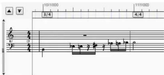
The result, as shown below in Figure 42-2, is that the entire Grand Staff display is transposed, as indicated above the treble clef, and the notes are displayed within the staff. Only the display gets transposed; the actual notes maintain their original pitches.

Figure 42-2: The Octave up/down buttons transpose the entire grand staff.
INSERTING, SELECTING & EDITING NOTES
The following sections describe basic procedures in the Notation Editor.
Inserting Notes
To insert a note on the grand staff:
1 Click the Pencil tool in the Tool palette (Studio menu).

Figure 42-3: Use the Pencil tool to insert notes in the Notation Editor.
2 Click at the desired pitch and location on the Grand Staff, drag to the right to draw the desired duration, and release the mouse.
The note's attack will begin at the nearest grid location. The duration is shown as a grey bar extending to the right. As you drag to the right, the duration of the note increases in sixteenth note increments. For example, to enter a half-note, drag eight increments to the right as shown below.
To insert a note, drag to the right...

3 To insert more notes of the same duration, click the Pencil. To change duration, drag to the right after clicking.
Selecting notes for editing
The techniques for selecting notes on the Grand Staff are the same as those for selecting notes in the MIDI Editor. To select a single note, click the note. The notehead will invert to indicate that the note is selected. To select several notes, Shift-click each one. Or, drag a selection box over them. Shift-click to select non-contiguous notes. To select all notes in the track, double-click any note.
Dragging Notes
To change the location or the pitch of a note, simply drag the note to the desired pitch or location. This can also be done with more than one note selected. As usual, Option/Alt-dragging will produce a copy of the originally selected notes, which can be used to quickly generate repeated phrases or chords.


If a note is displayed as several tied notes, you must click the first of the tied notes.
Editing Durations
To change the duration of a note:
1 Command/Ctrl-click the note.
If the note consists of several tied notes, you must click the first of the tied notes. A grey bar will appear to indicate the current duration of the note with respect to the Time Ruler.

2 Drag the handle of the grey bar to the left to shorten the note or to the right to lengthen it. The grey bar will show you the change in duration.

To change the duration of more than one note, select them and Command/Ctrl-drag any one of them.
When changing a duration in the Notation Editor, the new duration maintains any differences between its actual length and its displayed length. For example, if a quarter note ends 17 ticks after beat 2, and you lengthen it by one beat to beat 3, the release will still be 17 ticks after beat 3.
SCRUBBING IN THE NOTATION EDITOR
There are two ways to scrub in the Notation Editor:
- With the playback indicator — scrubs all play-enabled MIDI tracks. For more information, see "Scrubbing multiple MIDI tracks" on page 229.
- With the Scrub tool — see “Scrub tool” on page 352.
ZOOMING IN THE NOTATION EDITOR
The grand staff and continuous data grid in the Notation Editor can be zoomed similarly to the MIDI Editor, including all zooming shortcuts. See “Zooming” on page 331 and “Zoom menu shortcuts” on page 332.
GRAPHIC EDITING TECHNIQUES
All of Digital Performer's powerful graphic editing features are available in the Notation Editor. See "Graphic editing techniques" on page 334.
CHAPTER 43 QuickScribe Editor
OVERVIEW
The QuickScribe Editor is one of several edit windows in Digital Performer. To learn more about editors in general, see chapter 35, “Edit Windows” (page 339).
The QuickScribe Editor allows you to view and edit any number of MIDI tracks as standard music notation.
Digital Performer interprets unquantized MIDI data, notating it in a readable fashion without permanently quantizing the data, so your original performance is always preserved. In fact, the notation transcription engine used in Digital Performer has been recognized by industry experts as the best available in any music software program. Music is displayed and edited on a page on the screen exactly as it will print on your printer.
Notes can be inserted with the mouse, computer keyboard, or via MIDI step entry. You can also transpose and edit using all of Digital Performer's powerful commands in the Edit and Region menus.
The QuickScribe Editor provides intuitive text entry for preparing title pages, headers, footers, lyrics, and page numbers. It lets you adjust system margins, staff spacing, measure spacing, and other formatting. Arrangement features let you print out scores, lead sheets and other music documents that have been fine-tuned and consolidated for printing.
QuickScribe Editor Quick Reference 480
QuickScribe Editor mini-menu 481
QuickScribe Editor basics....483
Opening the QuickScribe Editor 484
The QuickScribe Editor title bar....484
The Track Selector 484
The QuickScribe transcription engine 484
The playback wiper 485
Getting around in the QuickScribe Editor 485
Zooming 486
QuickScribe options menu 486
Score options 487
Track options....488
Marker options....490
Measure numbers....491
Measure spacing 492
Set Score Length 492
Controlling page size....492
Adjusting system margins....492
Snap, Cursor, Selection, and Event Information ..... 493
The QuickScribe Tool Palette 493
Working with notes 493
Chord Symbols....498
Inserting a staff brace or bracket 500
The Dynamics Palette 500
Popup Meter Changes, key changes and tempos ..... 501
Working with text....502
Lyrics....506
Score Arrangement 510
Display-only and playback-only notes....515
Film Cues view 517
Printing 520
Exporting a musicXML file....521
QUICKSCRIBE EDITOR QUICK REFERENCE
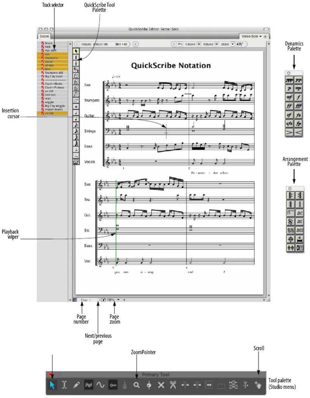
Figure 43-1: The QuickScribe Editor gives you a "what you see is what you get" notation window in which you can view, edit, and print your music.
Dynamics Palette: Provides graphic insertion of dynamics symbols.
Arrangement Palette: Provides symbols, such as repeat barlines and endings, that help to condense the display of the score for previewing and printing.
Insertion Cursor: Indicates the location at which notes will be inserted via computer keyboard entry and MIDI step recording. Click on the staff with the pointer to activate the insertion cursor, and then use the arrow keys to change its location and pitch.
Next/Previous Page: Scrolls to the next or previous page, if any.
Page number: Click on the page number and type in a different page number to jump directly to that page.
Page zoom: Provides preset levels at which to enlarge or reduce the size of the notation displayed in the window. You can also zoom with the Zoom tool in the Tool palette.
Playback Wiper: Indicates the main counter location. Drag it to scrub all MIDI tracks.
QuickScribe Tool palette: Provides mouse insertion of notes, dotted notes, triplets, text, lyrics, chord symbols, braces, brackets and note spellings.
Tool palette: When the QuickScribe Editor is the front-most (active) window, the Tool palette gives you access to the Pointer and Zoom tools, which both can be used in the QuickScribe Editor.
Track Selector: Click track names to show or hide them in the QuickScribe Editor.
QUICKSCRIBE EDITOR MINI-MENU
Go to Page: Provides sub-menu commands for scrolling to the next, previous, first or last page.
Go to measure: Jumps to the page containing the measure you specify.
Options>Score options: Provides many options for displaying the score in the QuickScribe Editor.
Options>Track options: Provides unique display options for individual tracks.
Options>Marker options: Provides options for the display of markers in the score.
Options>Lyrics options: Provides options for the display of lyrics in the score.
Options>Chord Symbol options: Provides options for the display of chord symbols in the score.
Options>Measure numbers: Provides options for the display of measure numbers in the score.
Options>Measure spacing: Provides options for how tightly or loosely notes are spaced in the score.
Options>Set Score Length: Lets you specify the length of the score, for both linear view and arrangement view. In linear view, the score length can also be determined automatically.
Edit System Margins: When checked, this menu item displays draggable system margins for the current page. QuickScribe provides separate system margin settings for the first page versus all subsequent pages. The system margins control the distance of staff lines, as well as all staff-related text like instrument names, from the edge of the page.
Print Individual Parts: Prints each staff currently being shown in the QuickScribe Editor as a separate part using the current system margin and page text settings. Each part is printed exactly the same way as it would if it were being displayed by itself in QuickScribe, including its part transposition, if any.
Tool Palette: This checkable menu item shows and hides the QuickScribe Editor tool palette.
Dynamics Palette: This checkable menu item shows and hides the QuickScribe Editor dynamics palette.
Arrangement Palette: This checkable menu item shows and hides the QuickScribe Editor Arrangement palette. These tools only work when you have selected Show Arranged Score (described earlier), except for the Time-Anchored text tool, which can be used in the linear score view as well.
Switch Staff: Moves the currently selected notes into the other hand on a piano (grand) staff.
Change Selected Notes to: Lets you specify notes as Display-only (silent) or Playback-only (hidden), change notes to small noteheads (or back to normal-sized noteheads), or change note durations to Automatic or Manual.
Split Selected Normal Notes: This command operates only on those selected notes that are normal, i.e. a note that is not set to be Display-only or Playback-only. This command replaces each selected normal note with two copies of itself: a Playback-only copy and a Display-only copy. The purpose of this command is to make it easy to start editing the appearance of a measure without changing the playback of the measure.
Display-only Notes: This sub-menu provides several commands for selecting, showing/hiding, and playing/muting notes that have been designated as Display-only notes (with the Change Selected Notes to mini-menu command described above).
Playback-only Notes: This sub-menu provides several commands for selecting, showing/hiding, and playing/muting notes that have been designated as Playback-only notes (with the Change selected notes to mini-menu command described above).
Show Lyrics: This option toggles the display of lyric text in the QuickScribe score.
Show Film Cues: This checkable menu item shows and hides the Film Cues View at the top of each system in the QuickScribe Editor.
Show Arranged Score: When checked, this menu item causes QuickScribe to display the arranged notation view. When not checked, QuickScribe will show the linear notation view. Initially, the arranged view will be the same as the linear view, except that certain tools and commands can be used only in the arranged view. In the arranged view, the score can contain repeats, endings, coda and segno symbols, and score jumps like D.S. al Coda (which the wiper will follow during playback). As you apply tools from the Arrangement palette and begin to “hide” and “move” measures, the arranged view will start to differ from the linear view. Changing the arranged view does not change the playback of the piece — it just changes the look of the score and changes where the wiper goes during playback (and makes your notation more readable when you print it out). See “Score Arrangement” on page 510 for a complete explanation of how to create and print out an arranged view of your score.
Show Alternate Bar Menus: Displays a small square pop-up menu next to each regular measure number displayed on the QuickScribe page. Each alternate bar menu shows all of the linear bars that
are currently associated with an arrangement bar. This menu item is only available when the Show Arranged Score command is checked. When working on an arrangement, also be sure that Show measure numbers is turned on (under Options> Measure Numbers), and that they are set to display on every measure.
Allow Measure Selection: When checked, this menu item lets you select entire measures by clicking and Shift-clicking on them with the QuickScribe arrow tool. When a measure is selected, you can then apply score arrangement operations to the measure (such as hiding, "popping-out" or moving them).
Clear Arrangement: Reshuffles the measures in the arrangement view back to a completely linear state where no bars are hidden. All consolidated rests are unconsolidated. Deletes all Coda, double Coda, Segno and double Segno symbols from the score, as well as all endings. It will NOT delete any time-anchored text, including time-anchored text boxes that were created using the D.C., D.S., or D.S.S. tool.
Do to Selected Measures>Hide: When you Hide a measure behind another measure, it disappears. But when playback reaches a hidden linear measure number, the wiper will jump to the measure where you "hid" it and wipe over that measure while playing the hidden linear measure. Use this feature to hide the second instance of repeated measures behind the first instance, or to hide the second and third verse measures behind the first verse measures.
Do to Selected Measures>Pop Out: Extracts the currently visible linear measure (in a selected arrangement measure that has several linear measures "hidden" in it) and places it just to the right of the arrangement measure you selected. After being liberated, you can then move the popped-out measure anywhere in the score (such as its original linear position). This operation is the opposite of “hiding” a measure.
Do to Selected Measures>Move: Positions the currently selected measure anywhere in the score. You will be asked where you want to move the selected measure to, and you then specify an arrangement measure location.
Consolidate Rests / Unconsolidate Rests:
Specifies the minimum number of consecutive empty measures that will be displayed as consolidated rests for all tracks currently visible. If a track is already set to consolidate rests in a certain way, it will continue to prefer that setting when it is shown by itself or in combination with other tracks.
Make Arrangement Markers: Creates markers for interesting points in an arranged score. In particular, a marker is created at the start of every repeat, at segno and coda marks, and at the start of each ending. Open the markers window to quickly navigate to the various parts of the arrangement. Markers can be shown or hidden in the QuickScribe Editor with the Show Markers check box in the Marker Options window.
Open Selected Ending Bracket: Gets rid of the small vertical line at the end of the currently selected ending bracket. Doing so implies that the reader of the score should continue on after taking the ending.
QUICKSCRIBE EDITOR BASICS
Digital Performer provides one QuickScribe Editor per sequence, and you can have an unlimited number of sequences in a Digital Performer project. For example, if you have three sequences, you could open three separate QuickScribe windows all at once, one for each sequence. To do so, you must first pop them out of the Consolidated window. To do so:
1 Click the QuickScribe tab in the Consolidated Window to view the QuickScribe cell.
If QuickScribe is the only cell in the center portion of the Consolidated Window at this point, the QuickScribe cell will not be allowed to "pop out" yet.
2 Drag down the horizontal window divider to create a second horizontal cell in the center portion of the Consolidated Window.
You'll now be able to pop-out the QuickScribe window.
3 Double-click the QuickScribe cell's pop-out area.
The QuickScribe window is now a separate window.
4 Play-enable the next sequence in the Chunks list and repeat this procedure to extract its QuickScribe window from the Consolidated window.
If you keep the QuickScribe window inside the Consolidated window, then there is only one QuickScribe cell that simply updates to display the currently play-enabled sequence.
Virtual paper
The QuickScribe Editor can display any combination of tracks in the sequence, and you can easily change what is displayed. Page formatting is preserved, even if you decide to change what is displayed in the window. The QuickScribe Editor is ideal for quickly printing scores and parts.
Unlike the Notation Editor, which employs linear note spacing aligned with a time ruler, the QuickScribe Editor uses engraver spacing so that the notation looks more natural for printing. In addition, the QuickScribe window displays staves on a page—essentially a virtual piece of paper—such that what you see on-screen is what you get when you print a QuickScribe score. QuickScribe automatically generates as many pages as needed to hold your score. The contents of the QuickScribe Editor can be printed at any time. This chapter explains all about preparing the appearance of the score. For information about printing it, see “Printing project windows” on page 30.
OPENING THE QUICKSCRIBE EDITOR
See “Opening edit windows” on page 341. The QuickScribe Editor window position, as well as the zoom setting, current page, and other aspects of the window, are saved with the file. In addition, the QuickScribe Editor can be saved with window sets.
THE QUICKSCRIBE EDITOR TITLE BAR
The QuickScribe Editor title bar contains the standard edit window items discussed in “Window Target” on page 343.
THE TRACK SELECTOR
Like other Digital Performer editors, the QuickScribe Editor has a track selector that lets you view multiple tracks at one time. See “Viewing multiple tracks in one edit window” on page 342.
THE QUICKSCRIBE TRANSCRIPTION ENGINE
The QuickScribe Editor employs a highly sophisticated transcription engine to interpret unquantized MIDI data as readable music notation. QuickScribe tries to write the music just like it sounds — perhaps like you might write it down if you listened to a tape of it and tried to transcribe it yourself by ear. Transcription is not an exact science, and QuickScribe does its best to take precisely recorded MIDI data (which is often played much differently than the way it is written), make “human” judgements about how it might be written, and then turn it into readable notation.
Floating split points and multiple voices
Digital Performer's QuickScribe Editor transcription engine is quite sophisticated. For example, it employs floating split points when notating a track on a grand staff, intelligently deciding whether notes should be written on the treble or bass clef staves. QuickScribe can also notate multiple voices on a single staff — that is, notes that have different rhythms happening at the same time in the same measure. But you don't really need to know any of this; the result of it all is that you get some of the best automated notation transcription available in music software.
Displaying triplets and tuplets
In addition to being able to properly display unquantized data, Digital Performer automatically detects triplets and tuples and displays them with the appropriate bracket and note spacing. In some cases, the placement of the notes in the tuplet may not be accurate enough for Digital Performer to properly detect the tuplet. If you'd like to see the tuplet properly displayed, try quantizing the data with the tuplet option in the Quantize command. Try experimenting with Strength settings less than 100%, as the tuplet does not need to be fully quantized for Digital Performer to recognize it. However, if all else fails, quantize the start time of all notes in a given measure to be sure that triplets and certain other rhythms will be detected.
Context sensitive note spelling
QuickScribe's transcription engine also takes into account the context in which an accidental is spelled. For example, in an ascending line, QuickScribe will use a sharp to notate an accidental, but use a flat in a descending line.
THE PLAYBACK WIPER
The playback wiper operates as usual in the QuickScribe Editor (see “Auto scroll” on page 226), with the following exception: since the QuickScribe editor employs engraver spacing for notes, it does not have a linear time ruler like
Digital Performer's other editors. Therefore, to make the playback wiper jump immediately to a particular location, double-click on a staff at the desired spot. To scrub, drag the wiper as usual. Note that you can drag it vertically to jump to the next or previous staff system. If you drag horizontally off the end of a system, the wiper will continue on to the next system at its current speed, as long as the mouse is held down. Continuing to drag left and right with the mouse will change the speed and direction of the “runaway wiper”.
GETTING AROUND IN THE QUICKSCRIBE EDITOR
Use the next/previous page buttons (Figure 43-1 on page 480) or the corresponding QuickScribe Editor mini-menu commands to scroll through each page and go to the first or last page. The mini-menu commands have the following keyboard shortcuts:
Mini-menu command Keyboard shortcut
| Next page N |
| Previous page P |
| First page F |
Last page L
You can also jump to a particular page by using the page number box at the bottom of the window.

Figure 43-2: Click the page number to go to any page.
Mouse wheel scrolling
If your mouse has a wheel on it, you can scroll the QuickScribe window vertically and horizontally with the wheel. To scroll horizontally, hold down the Shift key.
QuickScribe commands
There are many QuickScribe commands in the Commands window. These keyboard shortcut operations can greatly speed up your work in the QuickScribe Editor, and they can be fully customized. For details, search for “QuickScribe” in the Commands window (Setup menu).
ZOOMING
The contents of the QuickScribe Editor can be magnified and reduced with the following mouse techniques:
To do this: Do this:
| To go directly to a particular zoom magnification (such as 400%) | Choose it from the zoom menu at the bottom of the window (Figure 43-1 on page 480). |
| To zoom in with the Zoom tool | Select the Zoom tool in the Tool palette (Figure 43-1 on page 480) and drag over the desired area, or click to zoom in one level. |
| To zoom out with the Zoom tool | Option/Alt-click. |
| To zoom in with the Pointer tool | Select the Pointer tool and Option/Alt-drag over the desired area. |
| To zoom forward with the PointerOption/Alt-Control/Win-Shift-tool | click. |
To zoom back with the Pointer Option/Alt-Shift-click. tool
Keyboard zooming shortcuts
The QuickScribe Editor supports Digital Performer's zooming keyboard shortcuts for Zoom to Selection, Zoom to Selected Time Range, Zoom Forward/Back, Zoom to Setting, and Set Zoom Setting. These shortcuts are explained in "Zoom menu shortcuts" on page 332. They can be customized as explained in chapter 9, "Commands" (page 105). When zooming to a selection, QuickScribe zooms to the center of the area prescribed by the currently selected notes.
QUICKSCRIBE OPTIONS MENU
The Options sub-menu in the QuickScribe window mini-menu provides several commands for controlling the appearance of your QuickScribe score.

Figure 43-3: The Options sub-menu.
Separate QuickScribe options for three different QuickScribe views
Digital Performer maintains a separate set of score options for three separate QuickScribe views: Normal QuickScribe, QuickScribe + Film Cues, and Film Cues Only. (See “Three different QuickScribe views” on page 519.) When you enable one of the three different views, they are displayed with their own set of QuickScribe options. Four of the options dialogs shown above in Figure 43-3 (Score Options, Measure Spacing, Measure Numbers and Marker Options) contain a popup menu that lets you select which set of preferences you are editing:

Figure 43-4: Setting options for the three different QuickScribe views.
SCORE OPTIONS
Choose Score Options (Figure 43-3) to open the Score Options dialog box:
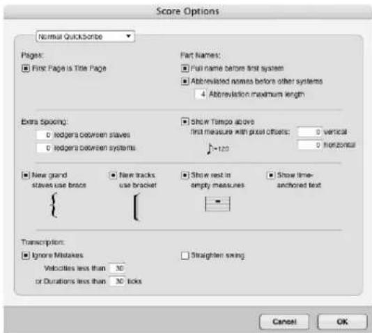
Figure 43-5: The Score options command in the mini-menu gives you many choices for laying out your score.
All score option settings are saved with the file, and they can be included in your New file template.
Creating a title page
The “First page is title page” option allows the first page of music to be formatted differently from the rest of the body pages. Its system margins can be adjusted separately from other pages to allow for a title, subtitle, composer, and other text. Text can be inserted on the title page without having it be displayed on other pages.
Full part names/Abbreviated part names
Two options are provided for displaying staff names, which appear between the left margin and the left edge of the staff. In both cases, the staff name is derived from the track name. Check the first option, Full name before first system, to display the full track name to the left of the first staff. Check the second option, Abbreviated names before other systems, if you would like an abbreviated name to appear next to each staff after the first one. By default, the abbreviation is the first four letters of the staff name, but this can be customized as explained in “Track name abbreviation” on page 490. If you don’t want staff names, uncheck both options.
The Abbreviation maximum length option lets you choose the maximum length of the default abbreviated staff names.
To set the font, style, size, etc. of all staff names, click any staff name and choose the desired text settings from the Text menu. The settings you choose will affect all staff names and abbreviations.
Adjusting the space between staves and staff systems
In addition to the space created above and below individual staves by their ledger line settings, you can make more space between staves and staff systems globally with the “Extra spacing” options. When you are printing a single track, use either option to increase the amount of space between the staves. If you are printing several tracks at the same time, they are grouped together into a staff system. Use the staff spacing option to increase space within the system; use the system spacing option to increase space between systems.
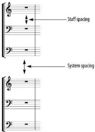
Show tempo marking above first measure
Digital Performer takes the tempo for the metronome marking from the tempo setting in the first measure displayed in the score. The tempo number is taken from the current settings in the metronome panel. For example, if the tempo control is set to the tempo slider, the current tempo slider setting is used. If tempo control is set to the Conductor track, the current tempo setting in the Conductor track is used.
The Pixel offsets option lets you adjust the position of the tempo marking. Positive offsets move the marking up and to the right. Negative offsets move it down and to the left.
System Bracket/Grand Staff Brace options
These two options let you choose whether or not new tracks should default to using a bracket or a brace. Brace and bracket groupings can easily be changed by using the brace and bracket tools in the QuickScribe Tool Palette.
Show rests in empty measures
You may choose whether or not to show a whole rest in empty measures (measures with no note data in them).
Showing/hiding time-anchored text
Use the Show time-anchored text option (Figure 43-5 on page 487) to show or hide time anchored text (“Time-Anchored Text” on page 503).
Transcription
The Ignore Mistakes options help clean up the transcription by ignoring (hiding) notes that have either a very short duration or a very low velocity—typical characteristics of notes that were played by mistake. You can adjust threshold for what is considered a “mistake” by adjusting the duration and velocity settings provided. The Ignore Mistakes option can be especially helpful when viewing performances with lots of grace notes or lead-ins. Note, however, that if you want to choose which notes to show on a case-by-case basis, you can also make any note invisible by setting it to be “playback only”. For details, see “Display-only and playback-only notes” on page 515.
When you check the Straighten Swing option, QuickScribe automatically writes swung eighth notes as straight eighths, instead of writing them as triplets with a triplet bracket. Only the display of the notes is affected. The actual MIDI data remains unmodified, so it will still play back with the original feel. This option is a great way to instantly clean up any score that was recorded with a swing feel.
TRACK OPTIONS
When displaying a track in the QuickScribe Editor, the Track options sub-menu command (Figure 43-3) lets you specify how you want it to be displayed, such as whether to display the track on a single staff or a grand staff.
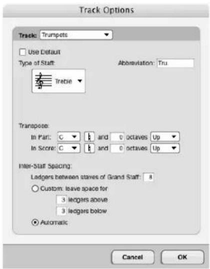
Figure 43-6: Track options.
Track menu
Choose each track one at a time from this menu and, below, choose the unique settings you want for each track. Settings are remembered. You can change them at any time. The “Default” item in this menu has its own settings, too; they are applied to any track for which you have checked the Use Default option (see below).
Use Default
This check box causes the track to use the default settings. To change the default settings, choose Default from the Track menu at the top of the dialog box.

Figure 43-7: The 'Default' track options.
Type of staff (and clef)
When viewing the track options for an existing track as shown in Figure 43-6, choose the desired staff type and clef from the menu provided.
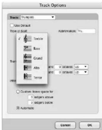
Figure 43-8: Choosing a staff type and clef for a track.
When viewing the 'Default' track options as shown in (Figure 43-7), you have five staff options.
Single staff
The Single staff option causes tracks using the default settings to be displayed on a single staff, regardless of what notes are in the track. When using a single staff, Digital Performer automatically chooses either a bass clef or treble clef in an effort to place most of the notes inside the staff and to avoid lots of ledger lines.
Grand staff
The grand staff option causes tracks using the default settings to be displayed on a grand staff, regardless of the notes in the track. Hand splitting is taken care of dynamically by Digital Performer's transcription engine.
Use single staff unless it requires more than \_\_\_\_ ledgers
This option causes Digital Performer to use a grand staff for the track if notes exist more than the specified number of ledger lines above or below a single staff. Use the ledger line option to control when a grand staff will be used instead of a single staff. Raise the number if you want to avoid using the grand staff very often.
Track name abbreviation
When viewing the track options for an existing track as shown in Figure 43-6, type in any track name abbreviation you wish in the text box provided. This custom name abbreviation overrides the "Default" track abbreviation (as specified by the track abbreviation settings in the Score Options mini-menu command).
When viewing the 'Default' track options as shown in (Figure 43-7), each track is given a default track abbreviation as specified in the Score Options (Figure 43-5 on page 487). See "Full part names/Abbreviated part names" on page 487.
Transposition
The Transpose settings specify a part (instrument) transposition for each track, as well as a score transposition. QuickScribe uses the part transposition when you view or print the track by itself; QuickScribe uses the score transposition when you view or print the track together with other tracks. You will most likely want to set the score transposition for each track to concert pitch, which is represented as C natural. For transposing instruments, choose the appropriate transposition. For example, you will also most likely want to set the part transposition for a B flat trumpet track to B flat.
Inter-staff spacing
These options give you control over the amount of space above and below the staff. This spacing is specific to the one track you are making settings for. To change the spacing of all staves, see “Adjusting the space between staves and staff systems” on page 487.
MARKER OPTIONS
Choose Marker Options (Figure 43-3) to display markers in the score at their location in the sequence. The marker text can appear above or below the staff, and you can control the distance from the staff by typing in a number of ledger lines in the box provided.

Figure 43-9: Marker options.
Displaying marker location
You can also choose to show the exact location of markers along with their name in any combination of Digital Performer's various time formats. Just check the box next to the time format you wish. This time is appended to the marker text:
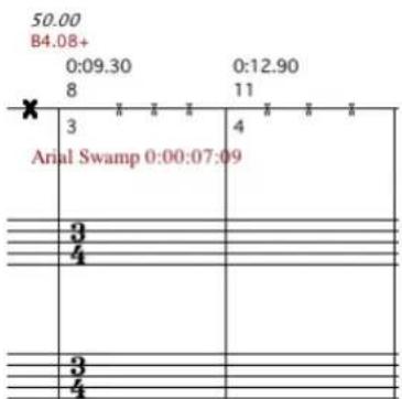
scatter
| X | Y | |---|---| | 3 | 4 | | 8 | 11 | | 11 | 11 | | 3 | 3 | | 4 | 4 | | 50.00 | 50.00 | B4.08+Figure 43-10: Displaying the marker (cue point) time in frames in Film Cues View.
Cascading overlapping markers
If markers occur close to one another, given the spacing of your score, you can use the Cascade overlapping markers option to force QuickScribe to cascade them vertically rather than overlap their names:

other
| Time | Value | | :--- | :--- | | 2 | 3 | | 4 | 3 | | 4 | 4 | | 4 | 3 | | 4 | 4 |Figure 43-11: Cascading overlapping markers in Film Cues View.
Hiding markers in a dense score
If you are using the _ measures per line measure spacing option, and measure spacing gets very dense, you can hide markers altogether with the Hide markers when showing _ or more bars per line option. When this option is enabled, and markers are being hidden, markers weighted Very Important remain visible and are displayed as dots.
Setting marker font, size, and style
To set the font, style, size, etc. of all markers, click any marker name and choose the desired text settings from the Text menu. The settings you choose will affect all markers.
MEASURE NUMBERS
The Measure numbers sub-menu command (Figure 43-3) sets the frequency and position of measure numbers in the score.

Measure number text formatting
Click any measure number displayed in the QuickScribe window to select all measure numbers and change their font, size and style using the Text menu. Changes apply to all measure numbers in the document. Changes are saved in the preferences for the current view (QuickScribe, QuickScribe + Film Cues, or Film Cues Only), so the setting can be made independently by view.
If you want a certain font, size or style to be the default for measure numbers, first make a file that has measure numbers the way you like them. Then save it as a file template (File menu> Save As Template) and check the Use as default New template option.
The measure numbers displayed just below the Show Film Cues staff (Figure 43-42 on page 518) cannot be formatted in this manner. They are displayed in a fixed font, size and style.
MEASURE SPACING
The measure spacing sub-menu command (Figure 43-3) lets you determine the number of measures per line or the overall spacing of notes.

Space measures \_\_\_\_ per line
This option lets you choose a certain number of measures per line, such as four or five. You can type in the desired number. With this option, each measure is the same size no matter what notes are in the measures.
If measures have lots of notes in them, use automatic spacing for best results.
Space measures automatically
This option lets Digital Performer decide how many measures to put on each line, depending on how many notes are in them. You can tighten or expand the overall spacing of measures by adjusting the slider. Its range depends on the music: don't hesitate to experiment with its full range. The QuickScribe score will update in realtime as you drag the slider.
In many cases (depending on the music itself), automatic spacing produces the best-looking results.
SET SCORE LENGTH
The Set Score Length sub-menu command (Figure 43-3) lets you determine the length of the score.
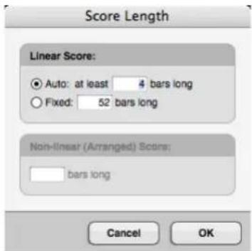
Linear Score
The “Auto” option lets Digital Performer determine how long the score is; however, it won’t be shorter than the minimum length specified here. The “Fixed” option sets the score to the exact length specified.
Non-linear (Arranged) Score
This specifies the length of the score when “Show Arranged Score” is enabled. This section is unavailable when “Show Arranged Score” is not enabled; likewise, when “Show Arranged Score” is enabled, the Linear Score section is unavailable.
CONTROLLING PAGE SIZE
The size of the page in the QuickScribe Editor is controlled by the Page Setup command in the File menu. Custom page sizes are not supported.
ADJUSTING SYSTEM MARGINS
System margins can be adjusted graphically by choosing the Edit System Margins mini-menu command in the QuickScribe Editor. Doing so causes system margins to appear on each page. The adjustments you make on any page will automatically be reflected on all other pages, except for the title page, if there is one. If the First page is title page option is enabled in the Score
options dialog (QuickScribe Editor mini-menu), the title page margins can be adjusted separately from the rest of the pages to allow for title text. In this case, you can adjust the system margins of the other pages by scrolling to any page besides the title page.
SNAP, CURSOR, SELECTION, AND EVENT INFORMATION
The Snap, Cursor, Selection, Event Information windows (Studio menu) display information about the current cursor position, selection range, and selected event. These windows update as you work, providing constant feedback.
The Information Bar can also be displayed directly in the QuickScribe Editor, showing some or all of the data shown in the Information windows.
For complete details about these information windows and the Information Bar, see chapter 37, "Information Windows" (page 355).
THE QUICKSCRIBE TOOL PALETTE
The QuickScribe Tool Palette allows you to insert notes, text, system brackets and braces, dots and tuplets. It also provides a tool for changing the enharmonic spelling of accidentals. The tools in this palette are explained in the following sections.
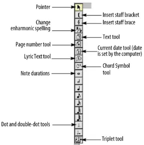
Figure 43-12: The QuickScribe Tool Palette.
Braces, brackets and barlines
Barlines extend across the staff systems that are grouped together with a brace or bracket.
WORKING WITH NOTES
The QuickScribe Editor allows you to do basic sequencing tasks, including inserting, step-recording, transposing, and editing notes.
You can insert notes with the mouse, the computer keyboard, or a MIDI keyboard. All three methods involve using the tool palette.
Rests are automatic
Rests are handled automatically by Digital Performer's transcription algorithms. You do not need to enter them.
Inserting notes with the mouse
Insert notes and other symbols with the mouse as follows:
To insert this Do this
| A note Click the desired note duration in the tool palette. Press anywhere in the measure where you want to insert the note. With the mouse still held down, drag to the desired pitch and location. Watch the Cursor Information window to help determine the beat location. | |
| A note with an accidental Same as above. | |
| A dotted note Click both the desired note duration and the dot in the palette. Then insert the same as above. | |
| A chord Insert the first note as described above.Click directly above or below the first note to add more notes to the chord. | |
| A triplet Click a note duration in the tool palette and click the triplet tool. Both are now selected. Insert each note in the triplet as described above. See “Displaying triplets and tuples” on page 485 for more information about triplet detection. | |
| To add a dot to a note Click the dot tool and then click on the notehead you want to add it to. | |
| To change the duration of Click the desired duration in the palette and click the note. | |
| To change several notes to Select the notes with the pointer.the same duration Command/Ctrl-click the desired duration or dot in the tool palette. Note: to scale durations (to double or halve them, for example) use the Scale Time command in the Region menu. |
To change the location or Choose the pointer and then drag the note pitch of one or more as desired. To drag multiple notes, select existing notes them before dragging.
Inserting notes with the computer keyboard
To insert notes and other symbols with the computer keyboard:
1 Click the Pointer tool in the palette.
2 Click on the staff at the desired pitch and location for the symbol.
A blinking insertion cursor appears on the staff.
3 After you have a blinking insertion cursor on the staff, refer to the following table:
To do this Do this
| To move the cursor Use the arrow keys. | |
| To determine the exact beat location and pitch of the insertion cursor | Use the Cursor Information window. |
| To select a duration Use the open bracket ( | ) and closed bracket ( | ) keys to choose the next highest and lowest duration. Or use the extended keypad (see "Selecting durations with the extended keypad" on page 494). Or click the desired duration in the palette. | |
| To add a dotted duration to press the d key to turn on the dotted duration tool; press it again to turn it off. | |
| To insert a note and advance Press return. | |
| To insert a note with an accidental | Press the + or - key on the extended keypad. |
| To insert the first note of a chord | Press the enter key. (Enter inserts the note without advancing the insertion cursor.) |
| To insert the second, third, fourth, etc. note in a chord | Press the enter key. |
| To insert a tuplet | Press the t key to turn on the tuplet tool, and use the bracket keys as described above to select any note duration. Press t again to toggle off the tuplet tool. |
| To delete a note or chord | Position the insertion cursor to the right of the note and press the delete (backspace) key. |
Selecting durations with the extended keypad
The extended keypad can be used to select durations in the QuickScribe tool palette during keyboard insertion, as shown below in Figure 43-13. On Windows, the Num Lock key must be engaged to enable these keypad shortcuts. These are the same duration keys used for Step Record. These QuickScribe keypad shortcuts are only available when there is an active insertion
cursor somewhere in the QuickScribe window. Otherwise, the keypad keys are bound to Digital Performer's standard transport shortcuts.
Command Keyboard shortcut
| Arrow tool |Clear| | |
| Tuplet[/] | |
| 64th note [8] | |
| 32nd note [7] | |
| 16th note [6] | |
| 8th note [5] | |
| Quarter note [4] | |
| Half note [3] | |
| Whole note [2] | |
| Dot | [.] |
| Double dot | [=] |
Mac: arrow cursor
Windows: Num Lock

Figure 43-13: When there is an active insertion cursor in the QuickScribe Editor (and it is the front-most window), the extended keypad provides these QuickScribe Tool Palette shortcuts. On Windows, the Num Lock key must be engaged.
Hearing notes while inserting them with the mouse
To hear notes played back on a MIDI device as you insert them, enable Audible mode (see “Audible mode” on page 337).
Step Recording notes with a MIDI controller To insert notes with a MIDI controller:
1 Click the Pointer tool in the palette.
2 Click on the staff at the location where you would like to begin entering notes.
A blinking insertion cursor appears on the staff. Use the Cursor Information window to determine the exact location in the measure. If necessary, use the Left Arrow and Right Arrow keys to move the cursor.

3 Select a note duration.
There are several ways to select a duration: 1) click the desired note duration in the tool palette, 2) press the open bracket ( [ ) and closed bracket ( ] ) keys on the computer keyboard repeatedly, or 3) use the extended keypad as described in "Selecting durations with the extended keypad" on page 494. The currently selected duration is displayed in the tool palette.
4 Play the desired note or chord on your MIDI controller.
Notes appear when you release the keys, so be careful not to slur notes together. It's best to play in a staccato fashion to avoid accidentally inserting two notes when you only want to enter one. If you would like to hold one note while inserting others, just keep holding it down while inserting the other notes.
5 Play as many notes and chords as you'd like.
Change durations as needed. Step Recording uses many of the same keyboard actions as computer keyboard entry, so you may want to review the section "Inserting notes with the computer keyboard" on page 494.
Getting the pointer temporarily
While working with the QuickScribe Tool palette, you may want to temporarily restore the pointer for selecting or some other purpose. To do so, press the Option/Alt key. While you hold it down, the cursor turns into a pointer. When you release the Option/Alt key, the cursor switches back to whatever it was.
Selecting notes for editing
Below is a summary of how to select notes for editing in the QuickScribe Editor. Notes are selected with the Pointer tool.
To select this Do this
| A single note Click it once. |
| Several notes that are not next to Shift-click each note.one another |
| The notes in several measures Drag a selection box over themeasures. |
| A region of notes Drag a selection box over them. |
All notes in the track Double-click any note
If a note is displayed as several tied notes, you can click any notehead to select the entire note.

When a single note is selected, its information appears in the Event Info window. This information can be edited as usual.
Dragging selected notes
To change the pitch of selected notes, drag them vertically. To change their time location, drag them horizontally. In either case, your action is constrained to the direction you first drag. For example, if you drag vertically to change pitch, your action is constrained to the vertical axis as soon as you begin dragging so that you don't accidentally move the notes in time as well. Conversely, if you drag horizontally first, your action is constrained horizontally so that you don't accidentally change pitch.
When dragging horizontally across multiple systems, you can drag to any staff in the system. (You are not limited to the original staff.)
Hold down the Option/Alt key when dragging notes if you want to drag copies of the notes.
Drag and drop from the QuickScribe Editor
You can drag and drop selected notes out of the QuickScribe window onto your computer desktop or into other Digital Performer windows. To do so, drag the material horizontally, not vertically, as vertical dragging is reserved for transposing the pitch.
Cutting, copying & pasting notes
After notes are selected as described in the previous section, they can be cut, copied, and pasted using the commands in the Edit menu. To paste notes you have either cut or copied, click the staff with the pointer on the location at which you would like to paste the material. Watch the Cursor Information window to specify the exact beat location at which you will paste. You can copy and paste between other editing windows as well.
Using Region menu commands
Similar to the Edit menu commands mentioned above. Any Region menu command can be applied to notes you have selected. This includes quantizing, transposing, and any other command from the Region menu.
Changing note durations
To change a note duration, click the desired duration from the tool palette and click on the note you wish to change. To change several notes at once, select them and then Command/Ctrl-click the desired duration in the tool palette.
Automatic vs. Manual durations
QuickScribe's transcription engine automatically displays notes with intelligent durations that are best for notation. The Change Selected Notes to Automatic Durations and Change Selected Notes to Manual Durations commands, available under the QuickScribe mini-menu's Change Selected Notes to sub-menu, let you change the display duration for selected notes.
Using Change Selected Notes to Manual Durations is somewhat like quantizing durations in QuickScribe without changing the actual durations in the MIDI data. It means, “Be more precise in how the durations are notated, instead of using durations that make live recorded MIDI data look simpler.” Using Change Selected Notes to Automatic Durations tells QuickScribe to use durations which may be less precise but produce simpler notation. Neither command changes the duration of the actual MIDI note event.
Controlling note spellings
Accidentals in the QuickScribe Editor are automatically calculated by the transcription engine.
Changing how an accidental is spelled
To change how an accidental is spelled:
1 Click the Change Enharmonic Spelling tool (Figure 43-12 on page 493).
2 Press on the notehead to the right of the accidental with the Change Enharmonic Spelling Cursor as shown below in Figure 43-14.
3 Choose the desired enharmonic spelling from the menu. Choose Auto to let QuickScribe automatically choose the spelling using context-sensitive note spelling algorithms.
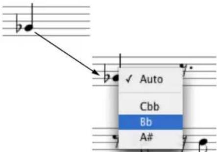
Figure 43-14: Changing the spelling of an accidental. Choose 'Auto' to let QuickScribe automatically choose the accidental using context-sensitive note spelling algorithms.
Moving a note into the left or right hand on a grand staff
The QuickScribe transcription engine employs sophisticated, context-sensitive algorithms to determine if a note should be written in the right hand (treble clef) or left hand (bass clef) on a piano staff. There may be times, however, where you'd like to manually override QuickScribe and move a note to the opposite staff. To do so, select the note and choose Switch Staff from the QuickScribe Editor mini-menu.
Changing the size of a notehead
Digital Performer offers two notehead sizes: normal and small. Small noteheads can be used for embellishments, cue notes, and other notational elements that call for small noteheads. To change the size of noteheads:
1 Select the notes.
2 From the QuickScribe window mini-menu, choose Change Selected Notes to> Small noteheads or Change Selected Notes to> Normal noteheads.
CHORD SYMBOLS
Chord symbols can be added to your score. Chord symbols are MIDI track events, and can be transposed along with MIDI notes.
Entering chord symbols
To enter a chord symbol, choose the Chord Symbol tool in the QuickScribe tool palette (C7) and click on or above the desired note. Alternatively, assign a keyboard shortcut to the Enter Chord Symbol command (Setup menu> Commands) and press the keyboard shortcut to enter a chord symbol above the selected note (or if there is no selection, above the playback wiper).
An empty chord symbol edit box will appear, ready for you to type in the symbol:
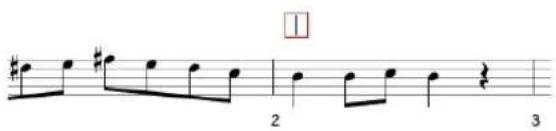
Figure 43-15: An empty chord symbol edit box
Type the desired chord symbol in the empty box. The first character, the root note, must be a letter A-G; after that, you may use any of the following symbols:
Symbol Description What to type
| # | sharp pound sign (#) | |
| b | flat B | |
| - | minor sign hyphen (-) | |
| ° diminished symbol Option/Alt-Shift-8 | ||
| ø half diminished symbol Option/Alt-O | ||
| ý | major 7th triangle | Option/Alt-J |
| 6/9 | 6/9 chord suffix | 6/9 |
| / | diagonal slash for hybrid chord, inversion, or altered bass | slash (/) |
| - | horizontal slash for a poly chord | underline (_) |
| any other text | the text itself | |
For chord suffixes, type the opening character, the desired suffix, then the closing character. Use these opening and closing characters:
Symbol Description What to type
| ( ) | stacked suffix with parentheses | Left parenthesis, Right parenthesis |
| { } | stacked suffix with braces | Left Braces ( { ), Right Braces ( { }) |
| [ ] | stacked suffix with brackets | Left Bracket ( [ ), Right Bracket ( ] ) |
| stacked suffix with no braces or brackets | Option/Alt-Backslash ( « ), Option/Alt-Shift-Backslash ( ») |
For example, to create this chord symbol:
C ^ 7 # 9 1 3
... type ^ C 7 (# 9 b 1 3) ^ .
After typing a chord symbol, press Enter or Return to confirm.
To enter additional chord symbols, press Tab or Shift-Tab to advance to the next/previous metric position in the measure (as determined by the "Tab key advances" preference explained below) or Option/Alt-Tab or Option/Alt-Shift-Tab to jump to the next/previous measure. If a chord symbol already exists at or before the next position that you will Tab or Shift-Tab to, the chord symbol will be selected for editing.
Transposing chord symbols
Chord Symbols are transposable along with other MIDI data. Select the desired chord symbols, with or without a MIDI note selection, and choose Region menu >Transpose. Select the “Transpose chord symbols” check box, choose the desired transpose options, and Apply.
Chord symbols in the Event List
Chord symbols are also displayed in the Event List. This is for display purposes only — chord symbols cannot be edited in the Event List. To edit chord symbols, use the QuickScribe Editor.
![Event List: Track-1 Track-1 + - Note 1[1]000 B3 ↓ 127 ↑ 127 ↔ 9|240 → 1|1|240 1[1]240 C4 ↓ 127 ↑ 127 ↔ 9|240 → 1|2|000 1[2]000 Eb4 ↓ 127 ↑ 127 ↔ 9|240 → 1|2|240 1[2]240 E4 ↓ 127 ↑ 127 ↔ 9|240 → 1|3|000 1[3]000 F#4 ↓ 127 ↑ 127 ↔ 9|240 → 1|3|240 1[3]240 E4 ↓ 127 ↑ 127 ↔ 9|240 → 1|4|000 1[4]000 Eb4 ↓ 127 ↑ 127 ↔ 9|240 → 1|4|240 1[4]240 C4 ↓ 127 ↑ 127 ↔ 9|240 → 2|5|000 2[1]000 Chord Symbol C7 2[1]000 B3 ↓ 127 ↑ 127 ↔ 1|000 → 2|2|000 2[2]000 B3 ↓ 127 ↑ 127 ↔ 9|240 → 2|2|240 2[2]240 C4 ↓ 127 ↑ 127 ↔ 9|240 → 2|3|000 2[3]000 B3 ↓ 127 ↑ 127 ↔ 1|000 → 2|4|000](/content/2026/05/834832/images/4095141edce93dd128b2a9feadcfa772c14325ece585927f82d9c81c839f17e0.jpg)
Figure 43-16: Chord symbol in the Event List
Hiding chord symbols
Chord symbols can be dragged freely within the QuickScribe score; hold the Shift key to constrain the drag horizontally or vertically, as described in "Shift-drag to constrain" on page 334.
The arrow keys can also be used to nudge the selected chord symbol up, down, left, or right.
Hiding chord symbols
To temporarily hide chord symbols, deselect "Chord Symbols" in the View Filter (Setup menu).
Chord symbols preferences
The Preferences window has a Chord Symbols pane to specify the default text style and tabbing behavior.

Figure 43-17: Chord symbol preferences
Text style
These options specify the default font, size, style, and vertical positioning of chord symbols.
Tab key advances
The options for Tab are to advance in one of three ways:
■ To the next beat or the next note, whichever comes first
■ To the next beat
■ To the next note
Apply To Score
The Apply To Score button applies changes made in the Chord Symbol preferences to the current project's QuickScribe score.
Setting preferences from existing chord symbol
The Commands window (Setup menu) includes a Use Chord Symbol Settings as Prefs command. If you select a chord symbol and invoke this command, the font, size, style and vertical offset settings for the selected chord symbol are copied into the Chord Symbol preferences for use by all new chord symbols.
This command is available only when you have a single chord symbol selected.
Setting preferences on-the-fly
Hold down the Control/Win key while dragging a chord symbol to set the resulting vertical offset of the chord symbol in the Chord Symbol preferences, which will be used by all new chord symbols.
INSERTING A STAFF BRACE OR BRACKET
The Staff Brace and Bracket tools in the QuickScribe Editor Tool Palette (Figure 43-12 on page 493) allow you to add and remove staff braces and brackets as desired to a staff system. Each staff can display—or be grouped by—one brace, one bracket or both. Each staff (track) remembers its brace/bracket status when you show or hide it. It might be useful to think of staff braces and brackets as an attribute of each staff that can be toggled on or off, rather than thinking of the brace or bracket as an object. With this in mind, below is a summary of how to add and remove brackets and braces:
To do this: Do this:
| To add a brace or bracket to a single staff or grand staff | Click the staff with the Brace or Bracket tool. |
| To remove a brace or bracket from a single staff or grand staff | Click the staff with the Brace or Bracket tool. |
| To add a brace or bracket to several adjacent staves | Drag over them with the Brace or Bracket tool. |
To remove a brace or bracket from Drag over them with the Brace or several adjacent staves Bracket tool.
THE DYNAMICS PALETTE
To open the QuickScribe Dynamics Palette (Figure 43-1 on page 480), choose it from the QuickScribe window mini-menu. This palette allows you to insert standard dynamic symbols, including hairpin crescendos and decrescendos.
Dynamic symbol placement
Dynamic symbols are associated with the nearest staff (track). If you show and hide the track, the dynamic symbol will show and hide with its track. When you insert or move a dynamic symbol, make sure it is closest to the track and measure to which it applies. In regards to time, dynamic symbols are associated with and remain at the measure and time location at which you place them, except as noted in the next section when moving them together with notes.
Working with dynamic symbols
Below is a summary of how to work with dynamic symbols:
To do this: Do this:
| To insert a dynamic symbol | Click the desired symbol in the palette and then click on the QuickScribe page. |
| To insert a crescendo/decrescendo | Click the Crescendo or Decrescendo tool and then either click or drag on the page. |
| To select one or more dynamic symbols | Use the same Pointer tool selection techniques as described in “Selecting notes for editing” on page 496. |
| To move a dynamic symbol | Drag it with the Pointer tool. |
| To duplicate a dynamic symbol | Option/Alt-drag it. |
| To move a dynamic together with notes | Select both with the Pointer tool and then drag the selected notes. |
| To copy and paste dynamic symbols | Select them (as described above), copy, click at the desired location to place the insertion cursor, and paste. |
| To copy and paste dynamic symbols together with notes | Select them both with the Pointer tool, copy, and then paste the notes as explained earlier in “Cutting, copying & pasting notes” on page 496. |
| To adjust the shape of a crescendo or decrescendo | See “Adjusting a hairpin crescendo/ decrescendo” below. |
| To remove a dynamic symbol | Click it with the Pointer tool to select it and the press the delete key. |
| To hide all dynamic symbols | Deselect “Dynamics Symbols” in the View Filter (Setup menu). |
Adjusting a hairpin crescendo/decrescendo
You can adjust the length and angle of a hairpin crescendo or decrescendo as shown below:

flowchart
graph TD
A["Drag this handle vertically to change the overall slope."] --> B["•"]
C["Drag this handle to change the size of the opening (height)."] --> D["•"]
E["Drag these handles to shorten or lengthen it."] --> F["•"]
B --> G["•"]
D --> H["•"]
F --> I["•"]
Figure 43-18: Adjusting a hairpin crescendo or decrescendo.
Closing the Dynamics Palette
To close the Dynamics Palette, uncheck it in the QuickScribe window mini-menu, or click the close button in its title bar.
POPUP METER CHANGES, KEY CHANGES AND TEMPOS
You can change meters directly on the QuickScribe page using the Arrow tool as follows:
To do this Do this
| To change an existing meter Click on it with the “4/4” cursor for a pop-up menu of options. | |
| To add a meter change after a key change | Click on the right third of a key signature with the “4/4” cursor to get the meter change popup. |
| To add a meter change at a measure that has no key or meter change | Click on the barline itself with the “4/4” cursor to get the meter change popup. |
Meter changes performed with the mouse always use the Only move barlines option ("Only move barlines" on page 752), and take effect until the next meter change. The metronome click value is set to the denominator of the time signature (except that for 6/8, 9/8 and 12/8 it is set to a dotted quarter note). For more options, use the Change Meter dialog in the Project menu>Conductor Track sub-menu.
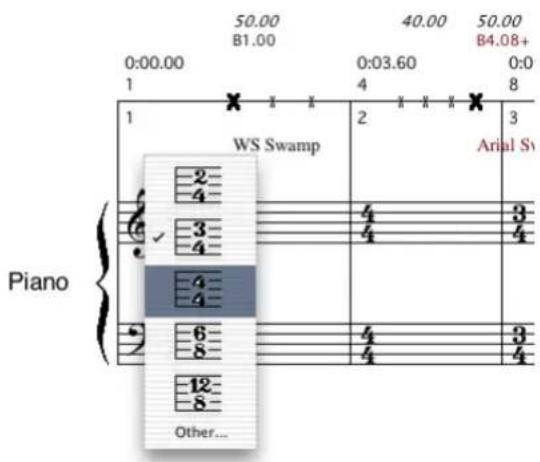
Figure 43-19: Changing meter in the QuickScribe window.
Popup Key Changes
You can change keys directly on the QuickScribe page using the Arrow tool as follows:
To do this Do this
| To change an existing key signature | Click on it with the “#/b” cursor for a popup menu of options. |
| To add a key change before a meter change | Click on the left third of a meter with the “#/b” cursor to get the key change popup. |
| To add a key change at a measure that has no key or meter change | Hold down the Option/Alt key and click on the barline itself to get the key change popup. |
Key changes performed with the mouse take effect until the next key change. For more options, use the Change Key dialog in the Project menu>
Conductor Track sub-menu. Note that popup key changes cannot be performed in the Film Cues only view, which does not display key signatures.

Figure 43-20: Changing key signature in QuickScribe.
Popup Tempo Changes
You can change tempo at the beginning of a measure directly on the QuickScribe page using the mouse. To do so, hold down the Control/Win key and click on any barline (or near the beginning of the first measure in a system) with the "bpm" cursor to get a simple Set Tempo dialog box.

Figure 43-21: Setting the tempo directly in QuickScribe.
Tempo changes performed with the mouse take effect until the next tempo change. For more options, use the Change Tempo dialog in the Project menu>Conductor Track sub-menu.
Tempo changes that you enter in the QuickScribe window are placed in the Conductor track. They display in the QuickScribe window only if you have set Digital Performer's main Tempo Control to Conductor Track as explained in "Tempo Controls" on page 213. Even then, only the tempo at the start of the first measure is displayed in QuickScribe via the metronome marking — unless you have checked Show Film Cues in the QuickScribe window mini-menu. Then all tempos that don't collide with other text in the Film Cues View will be shown in italics.
WORKING WITH TEXT
The QuickScribe Editor Tool palette has several text items that let you enter titles and other text on the page, including page numbers and metronome markings.
Text is handled in a similar fashion to standard computer graphics programs. Text is placed on the page inside text boxes, which can be cut, copied, pasted, and otherwise edited. A text box is a resizable, transparent box in which you can type and edit text. If you have worked with graphics software, you are already familiar with how to use text boxes in Digital Performer.
Inserting text
To insert text:
1 Scroll to the page on which you'd like to insert the text.
If you are inserting title page text, scroll to the title page. If you'd like the text to appear on body pages, scroll to any body page.
2 Click the Text tool in the Tool palette (Figure 43-12 on page 493).
3 As a shortcut, if you want the text to be time-anchored text (see "Time-Anchored Text" on page 503), hold down the Control/Win key.
4 Drag out a text box on the page.
5 Choose the desired font, point size, style, justification, and display properties from the Text menu. For details about the Display text attribute, see the next section, “Choosing where to display text”.
6 Type the desired text.
7 Click anywhere outside the text box to complete the text entry.
Choosing where to display text
The display sub-menu (in the Text menu) provides several ways to control where text appears in your score. Here is a summary:
Display menu item Explanation
| This page only Text only appears on the page on which it is entered. |
| Title page only Text only appears on the first page of the score. |
Body pages only Text only appears on body pages (all pages except the first page).
Both title & body pages 'Text appears on all pages.
| Time anchor left/center/right | Text is anchored to the linear measure where it is inserted. |
| On linear score only Text only appears when the Show Arranged Score mini-menu item is unchecked. | |
| On arranged score only Text only appears when the Show Arranged Score mini-menu item is checked. | |
| On These Parts Only Text only appears when one or more of the checked tracks in this submenu are showing in the QuickScribe window. | |
| On Single Part Only Text only appears when a single part (track) is showing in the QuickScribe window. When two or more tracks are visible, the text box will not appear. | |
The first two groups of items in the Display menu are mutually exclusive: either the text box is time-anchored in some way, or it is set to appear on title page/body pages/both. The last four items in the Display menu (linear or arranged score visibility; on specific track[s] or on single part displays) can be used with either type of text box.
Time-Anchored Text
Time-anchored text boxes stay with the measure where they are inserted. If the QuickScribe display changes in such a way that the measure moves to a different location on the page — or to a completely different page altogether — the text will stay with the measure. For example, if you change the measure spacing of the score, the text will move with the measure. Time-anchored text sticks to a particular time within a linear measure. If you “hide” a linear measure that contains time-anchored text (see “Hiding, extracting and moving measures” on page 511), the text will become invisible until the linear measure containing that time is made visible again.
Time Anchored Text will adjust its horizontal position on the page when notes are added or removed, or when anything else happens that changes the position and size of measures on the page. If the time-anchored text is not associated with a particular track (see “On These Parts Only” below), then its vertical position will always be a constant distance from the top of the system in which it appears. If the time-anchored text is associated with a particular track, then its vertical position will always be a constant distance from the top of the first staff for that track.
Time-anchored text is good for entering the names of chords over the top of each system, and for adding arranged score directions and labels like To Bridge, To Coda, and ritard. Time-anchored text that is also associated with a specific track can be used to enter textual directions that apply only to the performance of a specific part, or symbols that you want to attach to specific notes within that part.
Time-anchored text can be shown or hidden with the Show time-anchored text option in the Score Options dialog. See “Showing/hiding time-anchored text” on page 488.
On These Parts Only
When one or more of the items in this sub-menu are checked, the text box will appear only when one or more of the checked tracks are showing in the QuickScribe window. You can associate a text object with as many tracks as you'd like.
On Single Part Only
When this Display sub-menu item (in the Text menu) is checked, the text box will appear only when a single part (track) is showing in the QuickScribe window. When two or more tracks are visible, the text box will not appear. If both On "Track-1" Only and On Single Part Only are checked, then the text box will appear only when Track-1 is the only track showing.
Making titles, headers and footers
Titles, headers, and footers are inserted in the manner described in “Inserting text” on page 502. Just choose the appropriate Display attribute in the Text menu.
If the Title page only and Body pages only menu items are grayed out, check the First page is title page option in the Score options command located in the notation view mini-menu. For more information about this option, see “Creating a title page” on page 487.
Making page numbers
Page numbers are inserted using the Page Number tool (Figure 43-12 on page 493). Using this tool, insert them in the same manner as described in "Inserting text" on page 502. The page number automatically appears in the text box. Be sure to choose the appropriate Display attribute (Body pages only or Both title & body pages). See "Choosing where to display text" on page 503 for more information.
Displaying the current date
The current date can be inserted using the Date tool (Figure 43-12 on page 493). Using this tool, insert the date in the same manner as described in "Inserting text" on page 502. The current date (as specified by your computer) automatically appears in the text box. Be sure to choose the appropriate Display attribute (Body pages only or Both title & body pages).
Selecting text
To select an entire block of text, click it once with the Pointer tool. Handles appear to indicate that it is selected.
To select individual words within a text box:
1 Double-click the text box with the Pointer tool, or click once on it with the Text tool.
2 Select the desired text by dragging over it.
To select multiple text boxes, hold the Shift key while clicking on each text box, or make a lasso selection with the Pointer tool.
After text is selected, it can be cut, copied, or deleted. You can also change the font, style, and other attributes of the text.
Moving page text
Page text objects can be dragged freely within the QuickScribe score; hold the Shift key to constrain the drag horizontally or vertically, as described in "Shift-drag to constrain" on page 334.
The arrow keys can also be used to nudge the selected page text object up, down, left, or right.
Typing and editing text inside a text box
To edit text, double-click it with the Pointer tool (or click once with the Text tool) to get an insertion cursor inside the text box. After you have an insertion cursor inside the text box, use the following actions to edit the text:
To do this Do this
| Move the text cursor within the text box | Press the arrow keys |
| Delete a character Position the cursor to the right of it and press the delete key | |
| Select a word Double-click the word | |
| Select several words or sentencesDrag over them inside the text box | |
| Change the font, point size or style of some text in the text box | Select the text and choose the desired font, size, and style in the Text menu |
| Justify the text to the left margin, to the right margin or to the center | Choose Justify from the Text menu and select the desired justification |
| Finish inserting or editing the text | Click anywhere outside the text box |
| Cut, copy, and paste text within the text box | Select the text and choose the desired command from the Edit menu. |
Pasting text into Digital Performer from other programs
You can copy text from a text editing program such as Microsoft Word and then paste it into a text box in the QuickScribe Editor. Just copy the text from the other program, switch into Digital Performer, double-click or insert a text box, and then paste.
Changing text attributes
Text attributes like point size, style (bold, italic, etc.), justification (left, center, or right), and display properties (title page only, time anchored, arranged score versus linear score, etc.) can be changed after text has been entered.
To change the attributes of an entire text box, click the text once with the Pointer tool to select it. Then choose the desired attributes in the Text menu. This works for staff names, staff abbreviations, measure numbers and marker text as well.
To change the attributes of individual words within a text box:
1 Select the desired text as described in "Selecting text" on page 504.
2 Choose the desired text attribute from the Text menu.
3 Click anywhere outside the text box to complete the edit.
Installing fonts in the Text menu
The fonts that you see in the Text menu are the fonts that you have installed in your computer system. If you are not familiar with how to install text fonts in your computer system, refer to your computer documentation.
When troubleshooting font problems in Digital Performer, determine if the problem occurs in a word processor program, or other programs that deal with text. For example, if you can't find a font that should be in the list, check the font list in your word processor. Most likely, it will be missing there, too, and you then know that the problem lies somewhere in the computer system.
LYRICS
Lyrics can be added to your score in the QuickScribe Editor.

Figure 43-22: Lyrics in the QuickScribe Editor
Entering lyrics for a single track
To enter lyrics for a single track, choose the Lyric Text tool in the QuickScribe tool palette ( ) then click on or below the desired note. Alternatively, assign a keyboard shortcut to the Enter Lyric command (Setup menu> Commands) and press the keyboard shortcut to enter a lyric below the selected note (or, if there is no selection, below the note nearest to the playback wiper).
An empty lyric text box will appear, ready for you to type in:

Figure 43-23: An empty lyric text box
Type a single word or syllable in the empty box. To advance the edit box to the next note, press the space bar to start a new word, a dash (-) to enter another syllable in the current word, or an underscore (_ ) to extend the current word or
syllable to the next note. (Note, however, that you don't have to add underscores for a syllable that extends across tied notes —punderscores are added automatically beneath tied notes when you hit the space bar to go to the next non-tied note.)
To dismiss the lyric text box, press Enter or Return to confirm, or Escape to cancel.
Entering lyrics shared by multiple tracks
Lyrics can be associated with two or more tracks. For example, in a SATB choral score (Soprano, Alto, Tenor and Bass), you might have lyrics that are shared among the Tenor and Bass parts (tracks) for a portion of the score, or perhaps shared by all four parts. You can freely choose which parts the lyrics are associated with, at any time. For example, the four SATB parts might have individual lyrics for some sections of the score and shared lyrics for other sections of the score. You have complete control over which parts (tracks) the lyrics are associated with.
If you wish to associate lyrics for multiple tracks when first entering the text, simply select a note in each track at the location where you want the shared lyric text to begin, and then either click with the Lyric Text tool or press the Enter Lyric command keyboard shortcut, as usual. An empty lyric text box will appear, but its vertical position below (or between) the shared staves will be governed by the Lyrics Preferences. See “Lyrics placement” on page 510.
Working with shared lyrics
Lyric text that is shared among several staves, will appear with each staff that it is linked with, whether the staff is displayed by itself or together with shared tracks.
If you have existing lyric text on the page, and you would like to see which tracks it is linked with, click the lyric text box with the Arrow cursor to select it and choose Text menu> Display> On
These Parts Only. Tracks with check marks next to their names are linked to the lyric. Choose any track from this sub-menu to toggle its checked/unchecked status. Doing so will link/unlink the track to the lyric text, respectively.
You can freely assign and unassign lyric text to any track or tracks using the On These Parts Only submenu as explained above.
Editing lyric text
To edit existing lyric text, double-click the lyric. While the lyric text box is selected for editing, you can press Tab or Shift-Tab to advance to the next/previous lyric. Tabbing will go to the next or previous lyric that is linked with that same track or tracks. Be sure to keep this in mind when you are working on a section of a score that has lyrics linked to different tracks, as tabbing may not necessarily jump to the very next, adjacent lyric text box if it is not linked to the same tracks as the current text box.
The Lyrics window
The Lyrics window (Project menu) allows you to enter and edit lyrics into your score via a conventional text editor environment. The Lyrics window is particularly useful when you already have lyric text from another source (such as a word processor or email) and would like to add them to your score all at once using the Auto Flow command.

Figure 43-24: The Lyrics window
Auto Flowing lyrics
Follow these steps to Auto Flow lyrics into your score:
1 Open the Lyrics window and type or paste text.
2 Format the text so that it will flow properly onto the QuickScribe page, using spaces, dashes, and underscores as described in "Entering lyrics for a single track", above.
3 Select the portion of the text in the Lyrics window that you want to flow onto the QuickScribe page.
If you place the insert cursor anywhere in the Lyrics window, only the text after the insert cursor will be flowed. If you make a selection in the Lyrics window, only the selected text will be flowed. If you wish to flow all of the text in the Lyrics window, either place the insert cursor at the very top of the window, or select all the text in the window.
4 Select the tracks that you want to associate with the flowed lyrics.
If you don't make a track selection, then the lyrics will flow into the first visible track in the score, beginning at the first note at — or after — the playback wiper location. If you select a note in a track, the lyric will flow over the notes in that track only, beginning at the selected note. If you select notes in multiple tracks, the lyric will be “shared” by all of those tracks, and will flow over the combined notes in all of the selected tracks. See “Lyrics preferences” below for settings that control how lyrics are displayed for multiple tracks.
5 Click on the Auto Flow button to flow the selected lyric text into the selected tracks.
Reflowing text after making edits
The Lyrics window is not dynamically linked to the text in the QuickScribe score. Therefore, if you make changes in the Lyrics window, you will need to reflow the text afterwards to update the QuickScribe score. Remember, you can reflow just a portion of the lyrics by selecting just the edited text in the Lyrics window and then selecting the note in the score where you want it to reflow.
Erasing lyrics
To erase lyrics, use the Arrow tool to select the desired lyrics in the QuickScribe window and press the Delete key or choose Erase from the Edit menu.
To quickly erase a large section of lyrics, select a note in the part whose lyrics you want to erase and press the Erase in Track button in the Lyrics window. This will erase all lyrics in the selected part after the selected note.
Copying and pasting lyrics
Lyrics are not MIDI events; rather, they are a special kind of QuickScribe page text. Therefore, they will not copy along with notes if you cut and
paste sections of the notes themselves. You can, however, easily recapture the lyrics from the copied section to the Lyrics window and then reflow them into the QuickScribe score at the pasted location; see “Recapturing lyrics from the score into the Lyrics window”, below.
Hiding lyrics
To temporarily hide lyrics, deselect "Show Lyrics" in the QuickScribe mini-menu.
Lyrics in an arranged score
You can enter lyrics into a linear score and then arrange it. pOnce arranged, lyrics for verses will automatically stack on top of each other in verse sections. You can also arrange the score first, and then Auto Flow into the arranged score. In that case, the Auto Flow algorithm still flows the lyrics into each linear measure in turn, stacking the lyrics as needed in the second, third, etc. pass through the repeated sections.
Converting regular page text into lyrics
If you have projects containing regular page text that you would like to convert to lyric text, the Capture Non-Lyric Text command (Lyrics window mini-menu) pulls the text from page text objects in the score (excluding date/time and page numbers) and puts the resulting text into the Lyrics window. The text from each text object will appear on a line by itself in the Lyrics window, and all instances of two or more spaces will be reduced to a single space.
Once all of the page text is in the Lyrics window, you can edit it to add syllable breaks and extensions. Delete the old page text from the score and use the Auto Flow process to flow all of the text back onto the score as lyric text.
Recapturing lyrics from the score into the Lyrics window
The Lyrics window is not dynamically linked to the text in the QuickScribe score. Therefore, if you add new lyrics directly to the QuickScribe score or make edits directly on the score, these changes will not be automatically reflected in the Lyrics window. To update the Lyrics window text, you must recapture the lyrics from the score.
If you would like to send lyric text from the score to the Lyrics window, choose Capture Lyric Text from the Lyrics window mini-menu. This captures the lyric text for the tracks shown in the QuickScribe score; if there is a selection, only the lyrics in that time range will be captured.
To capture all text from the score (excluding date/time and page numbers), use the Capture All Text command.
Lyrics preferences
The Preferences window in the Digital Performer menu (macOS) or Edit menu (Windows) has a Lyrics pane to specify the default text style, placement, and syllable extension behavior of lyrics.

Figure 43-25: Lyrics preferences
Lyric text style
Options are provided to specify the font, size, and style of lyric text in the Lyrics window and on the QuickScribe page.
Lyrics placement
Various options specify the placement of lyric text on the QuickScribe page.
When specifying a vertical offset between two staves or tracks, the offset is the distance beneath the top staff or track.
Syllable extensions
By default, syllables are extended by underlining, but you can alternatively put a dash under each note.
Apply To Score
The Apply To Score button applies changes made in the Lyrics preferences to the current project's QuickScribe score.
SCORE ARRANGEMENT
The QuickScribe arrangement view is shown by selecting Show Arranged Score from the QuickScribe Editor mini-menu. The purpose of this view is to collapse a linear score into a compact arrangement using repeats, endings, and score jumps like D.S. al Coda. When you add a repeat in the QuickScribe arrangement view, it does not change the playback of the piece: it just changes the look of the score and changes where the wiper goes during playback (and makes your notation more readable when you print it).
In a linear score, measures are displayed consecutively as demonstrated below:

Figure 43-26: A linear score.
In an arranged score, you use repeat barlines, endings, and other similar arrangement symbols to condense the score. For example, when a repeat happens, the continuous linear measures are folded back on themselves, like a ribbon, for the length of the repeated section:
Arranged score bars:

Linear score bars:

flowchart
graph TD
A["1"] --> B["2"]
C["34567"] --> D["-"]
E["-"] --> F["-"]
G["-"] --> H["-"]
I[" "] --> J["→"]
Figure 43-27: In an arranged score, linear measures are folded back like a ribbon to share arranged score measures.
If, in the example above, we made the repeat a 2x (“two times”) repeat, meaning that you repeat twice instead of just once, the linear measures would flow through the arranged score like this:
Arranged score bars:

Linear score bars:

flowchart
graph LR
A["1"] --> B["2"]
C["3"] --> D["4"]
E["56789"] --> F[" "]
G[" "] --> H[" "]
I[" "] --> J[" "]
K[" "] --> L[" "]
M --> N[" "]
Figure 43-28: In this example, the repeat is taken twice, so measures 5 and 6 are included in the repeat, and therefore fall in measures 1 and 2 of the arranged score.
Figure 43-29 below shows an arrangement that has a repeat followed by first and second endings, along with how this would look in the QuickScribe arranged score.
Linear bars and Arrangement bars
A linear bar number is the number of the bar from the beginning of the unarranged piece, the number of the bar that appears in the global counter, and the number of the bar in every other editing window in Digital Performer. Every bar of music has a unique linear bar number. The first bar is linear bar 1.
An arrangement bar number is the number of the bar in an arranged score in QuickScribe. Each arrangement bar will be associated with one or more linear bars. In other words, if your chorus is visited three times during playback, then each bar of the chorus will have a single arrangement bar number, but will be associated with three different linear bar numbers.
Showing alternate bar menus
When working on an arrangement, you should turn on Show Alternate Bar Menus in the QuickScribe Editor mini-menu. This displays a small pop-up menu next to the regular measure number on the QuickScribe page:
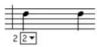

Figure 43-30: Showing alternate bar menus.
The alternate bar menu shows all of the linear bars that are currently associated with an arrangement bar. In the example above, arrangement bar 2 will be visited four times during playback: when the counter reaches linear bars 2, 4, 19 and 21. The checked item is the linear bar whose data is currently being shown. The rest of the associated linear bars are hidden.
When working on an arrangement, also be sure that Show measure numbers is turned on (QuickScribe Editor mini-menu> Options> Measure Numbers) and that they are set to display on every measure.
Hiding, extracting and moving measures
Most of the tools for arranging a score simply make cosmetic changes to it. There are only four operations that cause the wiper to jump around on the score during playback. One of them is rest consolidation, which will be discussed later. The other three all appear under Do to Selected Measures in the QuickScribe Editor mini-menu:
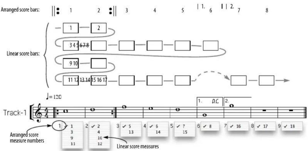
Figure 43-29: Above, linear bars are condensed into an arranged score with a repeat, combined with first and second endings. Below, this same example is shown as it would appear in the QuickScribe window, except that the alternate bar menus have all been opened simultaneously to show you which linear bars reside in each arranged score measure.
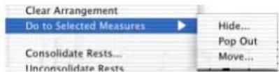
Figure 43-31: Use these commands to hide, extract and move measures in the arranged score.
Hide
When you "Hide" a measure behind another measure, it disappears. But when playback reaches a hidden linear bar number, the wiper will jump to the bar where you "hid" it, and wipe over that bar while playing the hidden linear bar. Use this feature to "hide" the second or third instance of some repeated measures behind the first instance, or to hide the second or third verse measures behind the first verse measures.
To hide a measure:
1 Make sure that Show Arranged Score is enabled in the QuickScribe Editor mini-menu.
2 Turn on Allow Measure Selection in the QuickScribe Editor mini-menu.
3 Click the Pointer tool in the QuickScribe tool bar.
4 Click anywhere in the measure you wish to select. Shift-click to select two or more measures.
You cannot hide a measure which contains hidden measures itself, so be sure to select a measure that has none.

Figure 43-32: Selected measures appear with a box around them.
5 Choose Do to Selected Measures> Hide.
You will be asked where you want to hide the measures. You must specify an arrangement measure location as the destination.
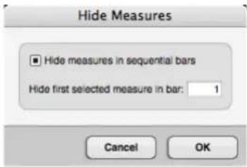
Figure 43-33: Choosing a destination for the hidden measures.
After you click OK, the selected measures will be hidden in the arrangement measures you specified. You can view them by choosing them from the alternate bar menu in that measure, as demonstrated below.

Figure 43-34: Hidden measures can be viewed by choosing them from the alternate bar menu.
Displaying hidden measures does not change playback
Note that when you hide a measure behind another measure, you do not change playback. If you have linear bars 2 and 4 associated with arrangement bar 2 in your arranged score, you can choose either linear bar as the representation that you want to see for that bar (as demonstrated in Figure 43-34). But choosing a linear bar for display purposes does not mean that those notes are going to play every time through the bar. The hidden linear bars always play exactly as recorded when it is their turn to play. The wiper will wipe over whatever representation is on the screen for that bar, but the performance of linear bars 2 and 4 will happen exactly as recorded regardless of what is on the screen (and on the printed page).
The Hide measures in sequential bars option
If the Hide measures in sequential bars option is unchecked, then all of the measures that you have selected will be hidden in the destination bar you choose. For example, if you've selected bars 7, 8 and 9, and you choose bar 1 as destination bar to hide them in, they will all go into bar 1. However, if the Hide measures in sequential bars option is checked, then bars 7, 8 and 9 will be hidden consecutively in bars 1, 2 and 3.
Locating hidden linear measures
To quickly locate a hidden linear measure, try entering that measure number in the global counter and hitting play. The wiper will jump to the arrangement measure where that linear measure is hidden. You can then select the hidden linear measure from the alternate measure popup next to the measure number in order to see it and edit its data. You can also use the Pop Out command (explained below) to extract it from that arrangement measure.
Pop Out
Pop Out is the opposite of Hide. If you select an arrangement bar that contains more than one linear bar, the Do to Selected Measures> Pop Out command (Figure 43-31 on page 512) extracts the currently visible linear bar and places it just to the right of the arrangement bar you selected. After being liberated, you can then move the popped-out bar anywhere in the score (such as its original linear position).
Moving measures
Do to Selected Measures> Move (Figure 43-31 on page 512) allows you to position a selected measure anywhere in the score. You will be asked where you want to move the selected measures, and you specify an arrangement measure location. This command is seldom needed, but will become necessary sometimes when you have multiple endings in a score, with other sections (like a bridge) occurring in between. After you finish collapsing the score, you may find that your bridge lies between your second and third ending, and the only way to get all of the endings together is to move the third ending measures just after the second ending measures.
A suggested approach to hiding measures
In general, when building an arrangement you want to start at the beginning of the piece and proceed forward. As soon as you encounter a measure that is another instance of a previously played measure, hide that measure under the previous instance. Later, you can use the alternate measure menu to select which linear measure instance is the best representation of the notation for a given arrangement measure.
The Arrangement palette
To open the QuickScribe Arrangement palette, choose it from the QuickScribe window mini-menu. The QuickScribe Arrangement palette contains tools that work only when you have selected Show Arranged Score from the QuickScribe Editor mini-menu, except for the Time-Anchored Text tool, which can be used in the linear score view as well.

Figure 43-35: The Arrangement palette.
Selecting any of these tools changes your cursor to an image of the tool, and allows you to click on the score to do something.
Begin Repeat: Click near a barline to enter a begin repeat. Click near the barline again to remove a begin repeat.
End Repeat: Click near a barline to enter an end repeat. Click near the barline again to remove an end repeat.
Fine Bar: Click near a barline to select where the Fine bar should go. There can only be one Fine Bar in the score, so if it is already present in a score, clicking with this tool will move the Fine Bar to where you click.
Thin Double Barline: Click near a barline to enter a thin double barline. Click near the barline again to remove a thin double barline.
Endings: Click and drag over a number of sequential measures to create an ending bracket. To extend an existing ending, hold down the Shift key and drag in the measures after the existing ending. (This is especially useful if an ending needs to extend across a page break.)

Figure 43-36: A first and second ending.
To adjust the height of an ending, uncheck Allow Measure Selection and then drag it vertically with the arrow tool. All ending brackets in the score are adjusted.
To edit the ending number, or change its font or style, uncheck Allow Measure Selection and then click the ending number with the Arrow tool.
To remove the vertical bar at the right-hand edge of the ending, click the ending with the Arrow tool to select it and choose Open Selected Ending Bracket from the QuickScribe Editor mini-menu. To get rid of an ending, click it with the Arrow tool to select it, and press the delete key.
D.C.: Click on the page to enter time-anchored text that says "D.C.". You can set the font, size, style, etc. of the text as described earlier in this chapter.
Segno: Click on the page to enter a time-anchored Segno symbol.
D.S.: Click on the page to enter time-anchored text that says "D.S.". You can set the font, size, style, etc. of the text as described earlier in this chapter.
Double Segno: Click on the page to enter a time-anchored double Segno symbol.
D.S. S.: Click on the page to enter time-anchored text that says "D.S.S.". You can set the font, size, style, etc. of the text as described earlier in this chapter.
Coda and Double Coda: Click on the page to enter a time-anchored coda or double coda symbol.
Consolidated Rest tool
Click an empty measure to consolidate it with another empty measure just to the right of it. To unconsolidate one measure within a consolidated rest, hold down the Control/Win key while clicking with this tool.
![Track-1 1=38 2 5 2 3 1=2 3=7 6=9 10=12 1 2 3 6 2 3 13[17] 14[24] 15=17 16=25 24=25 26=20](/content/2026/05/834832/images/3d42518ea0fa2b27a9c402139194924da7175b50397f47b546900910261e01b9.jpg)
Figure 43-37: Consolidated rests in an arranged score.
The Consolidated Rest tool makes small changes to a specific consolidated rest, whereas the
Consolidate /Unconsolidate Rests commands in the QuickScribe Editor mini-menu make changes to
all consolidated rests in the visible tracks. These operations change the pattern of consolidated rests for all tracks currently visible. However, if a track is already set to consolidate rests in a certain way with the Consolidate Rest tool, it will continue to prefer that setting when it is shown by itself or in combination with other tracks. This makes it possible to customize rest consolidation for each part individually, but still control the way rests consolidate when a specific combination of tracks are shown.
Consolidated rests automatically break at meter changes.
Time-Anchored Text tool
Use the Time-Anchored Text tool in the Arrangement palette just like the normal text box tool in the main QuickScribe Editor tool palette. However, this tool creates a text box that is anchored to a time in the score. For details, see “Time-Anchored Text” on page 503.
Use the Text menu in the main menu bar to select whether the time anchor is at the left, center or right of the text bounding box. You can also choose whether you want your time-anchored text to appear in the arranged view, the linear view, or both, and whether it should appear only when a certain track is showing, or when any single track is showing.
The Time-Anchored Text tool is just a convenience. You can actually create either type of text box with either text tool with these shortcuts:
■ If you are using the normal Text tool, hold down the Control/Win key to enter time-anchored text.
■ If you are using the Time-Anchored Text tool, hold down the Control/Win key to make normal text.
DISPLAY-ONLY AND PLAYBACK-ONLY NOTES
There may be times when you wish to hide notes in the QuickScribe window, but still hear them play back. For example, you may have played a grace note or other performance-related material that wouldn't normally be written as notation.
Conversely, you may sometimes wish to display notes in QuickScribe that don't play back, such as cue notes for individual instrument parts, or simplified notation for an embellished performance.
The QuickScribe window mini-menu lets you specify notes as playback-only (hidden) notes or display-only (silent) notes. Just select the notes and then choose Playback-only or Display-only from the QuickScribe Editor's Change Selected Notes to mini-menu command.
To change notes back to normal notes (i.e. they appear in QuickScribe and play back), choose Change Selected Notes to> Normal. If the notes are hidden (Playback-only), you'll need to display them in order to select them and turn them back into normal notes. See "Showing, hiding and selecting playback-only and display-only notes" below.
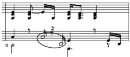
Figure 43-38: Above: the two circled notes will be turned into Playback-only notes. Below: the result.
Display-only and playback-only notes in the Event List
When you change notes into Playback-only or Display-only notes, they are annotated as such in the Event List:
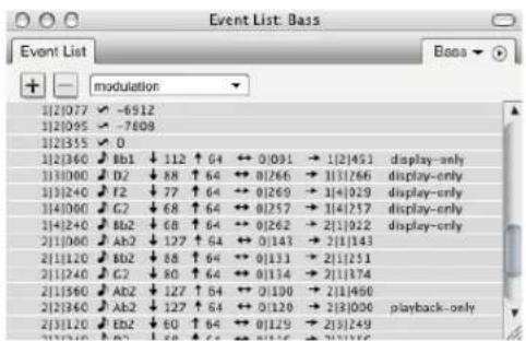
Figure 43-39: Playback-only and Display-only notes in the Event List.
Showing, hiding and selecting playback-only and display-only notes
In the QuickScribe Editor mini-menu, the Display-only Notes and Playback-only Notes submenus (Figure 43-40) let you select, show/hide and play/mute all notes in your score that have been designated as Playback-only or Display-only.

Figure 43-40: Controlling the display and playback of display-only and playback-only notes.
Temporarily viewing all playback-only notes To temporarily see all playback-only notes in QuickScribe:
1 Turn on (check) QuickScribe mini-menu>Playback-only Notes> Display.
2 Open the View Filter (Setup menu), deselect "Normal (display/play)" and "Display-only", and select "Playback-only".
Alternatively, to select all playback-only notes:
1 Turn on (check) QuickScribe mini-menu>Playback-only Notes> Display.
2 Choose QuickScribe mini-menu>Playback-only Notes> Select All.
Temporarily viewing all display-only notes To temporarily see all playback-only notes in QuickScribe, open the View Filter (Setup menu), deselect "Normal (display/play)" and "Playback-only", and select "Display-only".
Alternatively, to select all display-only notes:
1 Make sure QuickScribe mini-menu> Display-only Notes> Display is checked.
2 Choose QuickScribe mini-menu> Display-only Notes> Select All.
Split Selected Normal Notes
The Split Selected Normal Notes mini-menu command operates only on those selected notes that are normal. A normal note is a note that is not set to be display-only or playback-only. This command replaces each selected normal note with two copies of itself: a playback-only copy and a display-only copy. The purpose of this command is to make it easy to start editing the appearance of a measure without changing the playback of the measure. After issuing this command, you can then edit the display-only notes without affecting the (now hidden) playback-only notes. Just make sure that playback-only notes are set to be hidden (their Display sub-menu item as shown in Figure 43-40 is unchecked).
Finding hidden notes
If there is a note in the event list that is not showing up in QuickScribe, then one of the following is happening:
■ The note is being hidden from the QuickScribe Editor display due to the Ignore Mistakes settings in the Score Options dialog.
■ The note has been designated as a playback-only note, and playback-only notes are currently being hidden (the QuickScribe mini-menu>Playback-only Notes> Display setting is unchecked).
■ The note has been designated as a display-only note, and display-only notes are currently being hidden (the QuickScribe Editor mini-menu> Display-only Notes> Display setting is unchecked).
■ The note has been designated as a display-only or playback-only note, and display-only notes or playback-only notes are currently being hidden in the View Filter (Setup menu).
- The note is in a linear measure that has been hidden using the Do to selected measures> Hide command in the QuickScribe Editor mini-menu, and the linear measure is currently not being used to represent the arrangement measure to which it belongs. To view it, choose the measure from the alternate measure menu. If you can't find the hidden measure, see "Finding hidden notes" on page 516.
FILM CUES VIEW
The QuickScribe Editor can display film cues in a manner familiar to film composers. To see this view, open the QuickScribe window and choose Show Film Cues from the mini-menu:

Figure 43-41: Displaying Film Cues view.
When Show Film Cues is checked, the QuickScribe view includes an extra area of film cue information above the top staff in every system, as shown in Figure 43-42.
Tempo changes
As shown in Figure 43-42, the top line of information in this view (50.00, 40.00, 50.00) shows tempo changes in Beats Per Minute (BPM) in italic text.
Beat location
The next line of information in Figure 43-42 (B1.00, B4.08) shows the beat location of a cue point (marker), accurate to hundredths of a beat. These numbers appear only where a cue point falls within a measure. It is displayed with the same
color as the cue point text. In addition, beat location times are appended with a + or - sign if their associated cue point is late or early, in relation to the closest beat or half-beat. The hit range settings in the Markers window for the cue point's marker are considered when determining whether or not a cue point is hitting a beat or half-beat.
Measure start time
The next line in Figure 43-42 (0:00.00, 0:03.60, 0:09.30, etc.) shows the time at the start of each measure in minutes:seconds:hundredths of a second.
Beat number
Also at the beginning of each measure in Figure 43-42, two integers are displayed. The number above the horizontal line is the beat number from the beginning of the sequence. The number below the horizontal line is the measure number from the beginning of the sequence.
Beat marks
Each measure in Figure 43-42 shows a small "x" where the beats lie in the measure. If a cue point lies within the measure, then the nearest beat to the cue point is marked with a bold "X".
Cue points
The QuickScribe Film Cues view uses markers as cue points, as demonstrated below in Figure 43-42 by the words WS Swamp and Arial Swamp. To create or edit markers, choose Project menu>Markers. For complete details, see chapter 64, "Markers" (page 771). This section covers the specifics of marker operation with regard to the Film Cues View.
Markers appear in the same measure as their closest beat. By default, the Film Cues View does not display any marker whose weight is set to None in the Markers window. To change which types of markers appear on the QuickScribe page, use the Marker Options window. If the weight of a marker is set to Very Important, it appears in red. Use the Very Important weight to indicate markers that are key hits.

Figure 43-42: QuickScribe + Film Cues view.
Three different QuickScribe views
Digital Performer maintains a separate set of score options for three separate QuickScribe views:
QuickScribe view How to view it
| Normal QuickScribe Uncheck the Show Film Cues mini-menu item | |
| QuickScribe + Film Cues Check the Show Film Cues mini-menu item and display one or more staves in the QuickScribe window using the track selector. | |
| Film Cues Only Check the Show Film Cues mini-menu item and hide all staves in the QuickScribe window using the track selector. |
Film Cues Only view
If you use the track selector in the QuickScribe window to turn off all tracks, and if you have selected Show Film Cues in the QuickScribe mini-menu, then you will see a trackless Film Cues Only view shown below in Figure 43-43.
In the Film Cues only view, you can use the popup meter change and popup tempo change features described in “Popup Meter Changes, key changes and tempos” on page 501, but not the popup key change feature. Key signatures do not display in this view.
Default QuickScribe Options in the Film Cues Views
When you choose Show Film Cues for the first time in a document, Digital Performer will set the following default viewing options for optimal appearance:
| Setting | QuickScribeplus Film Cues Film Cues only | |
| Score options | ||
| Show rest in empty measures Off Off | ||
| Show tempo above first measure Off Off | ||
| Tempo mark pixel offsets(first measure) | V = -4H = -18 | V = -43H = -20 |
| Measure numbers | ||
| Show measure numbers Off Off | ||
| Measure spacing | ||
| Space measures _ per line On | 6 per line | On6 per line |
| Marker options | ||
| Show markers On | 5 legers abovesystem | On2 legers belowsystem |
| Measure time, real time, frametime | Off, off, off Off, off, off | |
| Show markers with weights All exceptmarkersweighted None | All exceptmarkersweighted None | |
| Hide markers when showing >= _bars per line | Off8 or more barsper line | On8 or more barsper line |
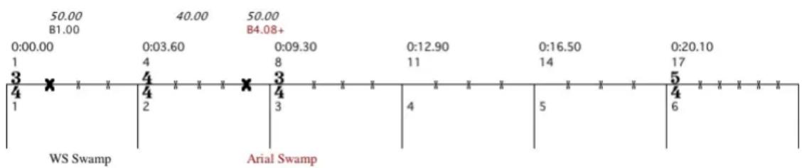
line
| Time | Value | | :--- | :--- | | 0:00.00 | 50.00 B1.00 | | 0:03.60 | 40.00 B4.08+ | | 0:09.30 | 50.00 B4.08+ | | 0:12.90 | 0:12.90 | | 0:16.50 | 0:16.50 | | 0:20.10 | 0:20.10 | | 1 | 1 | | 2 | 2 | | 3 | 3 | | 4 | 4 | | 5 | 5 | | 6 | 6 |Figure 43-43: Film Cues Only view.
You can change these options, and any other score options that you wish, in order to adjust the Film Cues view to your liking. Remember only that Show Markers must be turned on (Marker Options window) in order to see the names of your cues.
Displaying markers in Film Cues View
Use the Marker options dialog (Figure 43-9 on page 490) to set up how markers are displayed in the Film Cues View. See “Marker options” on page 490.
Changing the height of the Film Cues staff
You can change the height of the Film Cues staff simply by dragging it up or down. The staff height will be the same for every system in the document.

Figure 43-44: Adjusting the height of the Film Cues staff.
PRINTING
The following sections explain the procedure for various common printing tasks.
Printing instrument parts
To print instrument parts:
1 Use the Track Selector list (Figure 43-1 on page 480) to display a single track (instrument), and then format the page as desired (system margins, text, track name, etc.) as described in this chapter. To display the track name in front of the staff as the instrument name, use the Part Names option in the Score Options mini-menu command.
2 Use the Track Selector to show all tracks that you wish to print as individual parts.
3 Choose Print Individual Parts from the QuickScribe Editor mini-menu.
Each track currently being displayed in the QuickScribe Editor will be printed by itself using the formatting you arranged in step 1.
Preserving formatting for individual parts If you want to preserve the QuickScribe formatting separately for each track, you can do so by copying each track into its own separate sequence. Since each sequence has its own separate QuickScribe Editor, each part will be preserved.
Print Individual Parts and grouped tracks When using Print Individual Parts with tracks which are a member of an active track group, the grouped tracks will print together, once for each track in the group. For example, if you have four horn parts grouped together and you print them with Print Individual Parts, you will get four copies, each showing all four parts.
This is useful when printing out a copy for each member of the group. However, if you have grouped tracks which will be played by a single player, such as the individual elements of a drum kit, suspend the track group before printing with Print Individual Parts, or use File menu > Print.
Printing a keyboard part on a piano staff
To print a keyboard track on a grand staff:
1 Use the Track Selector list (Figure 43-1 on page 480) to display the track.
2 Choose Track Options from the QuickScribe Editor mini-menu.
3 Choose the track that contains the keyboard part from the Track menu.
4 Uncheck the Use Default check box, if necessary.
5 Choose the Grand Staff from the staff type menu.
6 Set the spacing options as desired and click OK.
7 Set the Score Options, text, margins and other formatting as desired.
8 Choose Print from the File menu.
Printing a score
When you display multiple tracks in QuickScribe, Digital Performer places them together in the same staff system. So, to print a score, use the Track Selector to show all tracks that you wish to include in the staff system for the score. To adjust the spacing between the staves in the system, as well as the spacing between systems, choose Score Options (QuickScribe Editor mini-menu).
Creating blank staff paper
To create blank staff paper:
1 Create one or more empty MIDI tracks.
2 Use the Track Selector to display the empty MIDI tracks in the QuickScribe Editor.
3 In Score Options, disable the “Show rest in empty measures” option.
4 In Measure Spacing Options, choose Space measures _ per line and set the number of measures per line as desired.
5 If necessary, you can lengthen the tracks (and therefore the number of pages) by extending the length of the sequence. To do so, choose QuickScribe Editor mini-menu> Options> Set Score Length.
EXPORTING A MUSICXML FILE
MusicXML is an XML-based file format for representing Western musical notation. It is a proprietary file format developed by Recordare LLC that is fully and openly documented, and it can be freely used under public license. For further information, visit musicxml.com.
MusicXML can be used to export a Digital Performer QuickScribe score to other programs that support MusicXML importing, such as Finale™ and Sibelius™. For a list of music software applications that support MusicXML, visit musicxml.com/software.
What gets exported
Digital Performer exports the following elements of a QuickScribe score:
■ Notation transcription, as it appears in the QuickScribe window
■ Key signatures
■ Meter changes
■ Dynamic markings
■ Lyrics
■ Transpositions
- Marker text
■ Tempo changes (requires that the tempo source is set to Conductor Track)
As of this writing, the following elements are not exported, although future versions of Digital Performer may support these elements as well:
■ Score arrangement markings (repeats, endings, etc.)
■ Chord symbols
■ Page text
Exporting a MusicXML file
To export a Music XML file, choose File menu> Export. In the resulting sub-menu, there are two MusicXML export commands.
Export> Selected Tracks As MusicXML:
Exports the currently selected tracks, which can be selected in any edit window. If no tracks are currently selected, then all MIDI tracks are exported.
Export> Score As MusicXML: This command is only available when the QuickScribe window is open, and it exports whatever is currently being shown in QuickScribe.
Tips for exporting MusicXML
Importing MusicXML files into Sibelius, Finale or any program that imports this file format is a simple and straightforward process. The key to smooth transfers is preparing the score in Digital Performer to make sure all the information you require is included in the exported MusicXML file.
Here are some things to check before exporting a Digital Performer project as a MusicXML file.
Key signatures
It is easy to work in Digital Performer without specifying a key signature. Therefore, be sure to choose Project>Conductor Track>Change Key to place a key signature at measure one (and any other locations in the score where the key changes).
Tempos
Digital Performer will include all tempo changes as metronome markings in the MusicXML file. However, you must have the conductor track selected in Tempo Control Menu as your tempo source to have all your tempo changes included. If you have another source selected, it will only include a metronome marking on measure one of the exported MusicXML file.
Markers
Digital Performer will include all markers as staff text attached to the top staff of the exported score. You may find it helpful to go through your project and add markers at all the important points to make them easier to find when you import the MusicXML file into your notation program.
Instrument transpositions
The transposition of each track in the score is dictated by the transposition of the instrument's staff in the QuickScribe score. If, for example, you have a trumpet staff set to C transposition in the score and B flat transposition in the part, the exported MusicXML file will use the C transposition (not B flat). If you require the trumpet to be in B flat, you will need to change the staff to B flat transposition in QuickScribe score before exporting. Alternately, you can change the instrument definition in your notation program after you import the MusicXML file.
Selecting which tracks to include
You may have a project with many tracks that do not need to be included in the exported MusicXML file, such as key switch control tracks, synth tracks, etc. In this case, go to the Track list, select only the tracks you wish to export and use the Export>Selected Tracks as MusicXML command.
If you have tracks organized into track folders, you can select a folder (or folders) and just those tracks will be included in the exported MusicXML file.
Importing MusicXML files into Finale
Once you have exported your Digital Performer project as a MusicXML file, it can be imported into Finale 2014 (and several earlier versions) by following these steps.
- From the Launch window, click on the "IMPORT MUSICXML" button. Locate the MusicXML file you have exported from Digital Performer on your hard drive and click the open button.
or
- Go directly to the File menu and select Import>MusicXML... Locate the MusicXML file you have exported from Digital Performer and click the open button.
Finale now opens the MusicXML file as Finale score.
Importing MusicXML files into Sibelius
Once you have exported your Digital Performer project as a MusicXML file, it can be imported into Sibelius 6, 7 or 7.5 by following these steps.
Sibelius opens MusicXML files the same way it opens Sibelius score files.
■ From the Quick start window, click the Open Other... button in the lower left corner, locate the MusicXML file you have exported from Digital Performer on your hard drive and click the open button.
or
- Go directly to File menu bar, select Open, locate the MusicXML file you have exported from Digital Performer and click the open button.
The Open MusicXML File window appears. Here you can specify paper size, house style and instrument options. Explore these options and see what best fits your workflow. Generally speaking, the default settings with the house style you need for your project works well.
Sibelius now opens the MusicXML as a Sibelius score.
CHAPTER 44 Waveform Editor
OVERVIEW
Digital Performer's Waveform Editor window provides a complete ‘destructive’ waveform editing environment. Permanent modifications can be made to mono, stereo, and multi-channel audio files using the standard editing commands in Digital Performer's Edit and Audio menus, including the ‘destructive’ application of MOTU Audio System effects plug-ins. Pencil tool editing is provided, even when zoomed out. Many navigation, selection and auditioning features are provided, along with dozens of key bindings for quick, convenient operation from your computer keyboard. Basic sample loop editing is also provided. A special feature, automatic crossfading, can be applied to all edits for artifact-free editing. The Waveform Editor also lets you view and edit soundbite beats and tempo maps.
Waveform Editor quick reference....526
Tool palette quick reference....527
Waveform editor mini-menu....528
'Destructive' editing 528
Opening the Waveform editor....529
The Waveform Editor title bar ....529
Snap, Selection, and Event Information ....530
Cursor Information....530
Cursor Guidelines .... 530
Grid lines....530
Waveform Editor edit grid ....530
Edit Layers....531
Transport lock....531
Selection....531
Global time format....531
Undo History....531
The audio file overview ....532
The Audio layer 532
Selecting with the I-Beam cursor....534
Making an insertion point....535
Auditioning....535
Scrubbing....536
The Audio Layer menu ....536
The Soundbites layer....536
The soundbites Layer menu 538
The Loops Layer 538
The Loops menu 540
Soundbite and loop shortcuts....541
The Pitch layer ....541
The Beats layer 541
The Beats menu....541
The Tempos layer ....541
The Tempos menu ....541
The Stretch Layer....541
The Bite Volume layer 542
Creating a new, empty audio file ....542
Creating a new audio file from a selection....542
Edit menu operations....542
Region and Audio menu operations....543
Waveform Editor preferences ....544
WAVEFORM EDITOR QUICK REFERENCE
Transport lock: Links playback and selection to the controls in the main control panel.
Waveform z oom: Scales the waveform vertically.
Transport lock: Locks playback of the audio file displayed in the Waveform Editor to Digital Performer's main transport controls.
Toggle grid lines: Shows/hides horizontal and vertical grid lines.
Togg le curs or gui delines : Shows/hides guidelines when moving the cursor over the waveform.
Close-up lens: Represents the area of the audio file currently being shown in the main waveform editor display (below the overview). Drag it to move it. Drag its edges to expand or contract the view.

Figure 44-1: The Waveform Editor shows the parent audio file of the currently selected soundbite. The entire audio file is shown in the overview at the top. The 'Close-up Lens' controls what area is displayed in the main view below.
Currently active soundbite: The currently active soundbite appears in black here in the Waveform layer. In the Soundbites layer, it has emphasized borders and a title bar, and you can sample-accurately edit it, make a selection from it, zoom to its boundaries, move to the next or previous soundbite, and other useful tasks.
Waveform Editor tab: Click it to display the Waveform Editor.
Audio file tab: Displays the name of the audio file being viewed in the Waveform Editor. Click it to choose a different audio file.
Waveform Editor mini-menu: Provides features specific to the Waveform Editor.
Audio file overview: Provides an overview of the entire contents of the audio file currently being displayed in the window.
Zoom to fit: Click these buttons to zoom all the way out so that the entire audio file fills the available space horizontally or the waveform fills the full amplitude range vertically.
Zoom to active soundbite: Fills the waveform display with the currently active soundbite.
Zoom to selection: Fills the waveform display with the current selection, if any.
Edit Layer: Lets you choose an edit layer for waveform display, including audio data, pitch automation, beats, tempo, stretching, volume, soundbites and sampler loops.
Edit Layer menu: Provides features specific to the current edit layer.
Waveform /spe ctrog r am menu : Switches between the standard waveform display and the spectrogram display, with numerous color options for the spectrogram. See “The spectrogram display” on page 383 for details.
Soundbite menu: Choose the currently active soundbite.
Amplitude ruler: Measures the gain of the audio samples in the waveform display. The range is from +1 to -1. For the spectrogram display, the ruler displays frequency in hertz (Hz), from zero to 21.1 kHz.
TOOL PALETTE QUICK REFERENCE
Pointer: Gives you an I-Beam cursor over the waveform for placing an insertion point and selecting regions of audio for editing. Also gives you a Hand tool in Soundbites editing mode that lets you select and edit soundbites by clicking and dragging their left or right edge.
I-Beam: Gives you an I-Beam cursor over the waveform for placing an insertion point and selecting regions of audio for editing.
Pencil: In the waveform edit layer, drag the Pencil tool over the waveform to redraw the sample data in the audio file. In other layers, the Pencil inserts data relevant to that layer (tempo, beats, volume, etc.)
Zoom: Click or drag to enlarge the waveform. Option/Alt-click to zoom out. Option/Alt-Shift-click to zoom backwards (through previous zoom levels). Option/Alt-Control/Win-Shift click to zoom forwards.
Scrub: Gives you a scrub cursor over the waveform for scrubbing and selecting while scrubbing.
Mute beats: Disables or re-enables a beat in the Beats edit layer.
Scissors: Use the scissors tool to split soundbites or pitch bars in the Pitch layer.
Trim: The Trim tool allows you to click anywhere in a soundbite to move the right edge to the location where you clicked. Hold down the Option/Alt key to move the left edge of a soundbite.
Scroll: Allows you to scroll the note grid and continuous data grid smoothly and precisely, vertically and horizontally in a single gesture. Simply click anywhere in the grid and drag as desired.
WAVEFORM EDITOR MINI-MENU
New Audio File: Creates a new, empty mono, stereo or surround audio file.
New Audio File from Selection: Creates a new audio file based on the current selection in the waveform editor or soundbite list.
Import Audio: Imports audio files and their soundbites into Digital Performer.
Export Selected Soundbites: Lets you save the currently selected soundbites as a separate audio files in one of several different audio file formats, including interleaved, AIFF, WAV and MP3 files.
Columns Setup: Lets you show and hide the columns in the Soundbites list.
New Soundbite Folder: Adds a folder in the Soundbite List. This is unavailable when using the Waveform Editor (and is only available when you are viewing Folders in the Soundbite list).
Waveform Editor Preferences: Lets you choose how stereo files are displayed in the overview. Also lets you make several settings regarding how edits are handled.
Remove from list: Deletes the soundbite from the Soundbites window list without deleting its corresponding region in the audio file region list.
Delete: Removes the selected soundbites from the list. This command does not delete audio data on the hard disk. It removes Digital Performer's reference to the data from the Soundbites window. If the soundbite is the last one in the parent audio file to be deleted, Digital Performer asks if you would like to delete the parent audio file entirely.
'DESTRACTIVE' EDITING
The phrase destructive editing has been adopted by the audio industry as a way of referring to the process of permanently altering the audio data in an audio file. The Waveform Editor window allows you to apply all of Digital Performer's editing capabilities 'destructively' to an audio file, permanently modifying the original audio data.
In all other Digital Performer windows, audio editing is non-destructive. The original audio data remains unaltered, and you merely modify pointers (references) to the original audio data. For example, if you cut a portion of a soundbite in the Tracks window or Sequence Editor, you are simply modifying pointers to the original audio data, but the original audio data remains unaltered.
On the other hand, if you cut a portion of a soundbite in the Waveform Editor, you are removing the actual audio data itself from the audio file. This will affect any soundbites that refer to the removed portion of the file. In some cases, this is a good thing, such as when you are removing a click or pop with the Pencil tool (you want the click to be removed in all cases where the audio is being used). But in other cases, you could alter soundbites that you didn't intend to. So keep this in mind when making destructive edits.
If you find yourself in a situation where you made a destructive edit that you wish you could “take back”, Digital Performer has a powerful unlimited undo history feature, discussed later in this chapter, that allows you to remove destructive edits and restore the audio file to its original state.
OPENING THE WAVEFORM EDITOR
There are several ways to open the Waveform Editor:
Location What to do
| From the Soundbites window Double-click a soundbite. This opens a separate Waveform Editor window for the parent audio file of the soundbite. |
| From other windows Select a soundbite and choose Edit in Waveform Editor from the Audio menu. |
| Sequence Editor Command/Ctrl-double click |
| Consolidated Window Click the "Waveform" tab |
| Any window Invoke the Display soundbite in |
| Waveform Editor command with your customized keyboard shortcut. Search for this command in the Commands window (Setup menu) and assign it to any key you wish. |
The Waveform Editor displays the parent audio file of the soundbite you click. It displays only one mono, stereo or surround audio file at a time, although you can open multiple waveform editors as explained below in the next few sections.
Opening a separate Waveform Editor window
Double-clicking on a soundbite in the Soundbite window list opens a separate Waveform Editor window. The window's title bar displays the name of the audio file.
Another way to open a separate Waveform Editor is to select a soundbite and choose Edit in Waveform m Editor from the Audio menu.
Opening multiple editor windows
Using the techniques discussed above, Digital Performer allows you to open a separate waveform editor window for each audio file being used in your project. For example, if your project currently has 20 soundbites in it, but they collectively belong to three separate audio files, you could open three separate Waveform Editors (one for each audio file).
THE WAVEFORM EDITOR TITLE BAR
The Waveform Editor title bar contains the standard edit window items discussed in "Window Target" on page 343. However, the Waveform Editor's Window Target menu switches between audio files, rather than tracks or sequences.
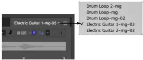
In addition to the standard items, when the Waveform Editor is out of the Consolidated Window the name of the parent audio file is displayed in the title bar. In macOS (only), you can drag the file icon to a Finder location to move the parent audio file on disk. Hold the Option key while dragging to copy the file instead of moving it, or hold Command-Option to create an alias to the file.
If you drag the file icon to a track in your project, the file will be added to your sequence. This works just like dragging a file into your project from the computer desktop.
If you would like to drag a specific soundbite to your project, either drag the title bar of the active soundbite in the Waveform Editor to your sequence, or drag the soundbite from the Soundbites list or Content Browser.
SNAP, SELECTION, AND EVENT INFORMATION
The Snap, Selection, Event Information windows (Studio menu) display information about the current selection range, selected event, and more. These windows update as you work, providing constant feedback.
The Information Bar can also be displayed directly in the Waveform Editor, showing some or all of the data shown in the Information windows.
For complete details about these information windows and the Information Bar, see chapter 37, "Information Windows" (page 355).
CURSOR INFORMATION
As with other Edit Windows, the Waveform Editor uses the Cursor Information window and/or Information Bar to display the position and value of the cursor.
File
Shows the name of the audio file currently displayed in the window.
Time
Time shows the cursor's current location in the audio file, in the time formats specified in the Cursor Information section of the Time Formats window (see “Customizing the time format display” on page 101).
■ If viewing Samples, the very first sample in the file is number zero (0).
■ If viewing Measures, the start of the active soundbite will be measure 1. If the soundbite contains a sync point, the sync point will instead become measure 1.
Amplitude
Amplitude shows the cursor's current vertical position in the waveform display. It is measured on a scale from -1 to 1.
For more information, see “Cursor Information” on page 358.
Waveform Amplitude
Waveform Amplitude shows the amplitude of the sample currently beneath the cursor. This value only appears when you are zoomed in far enough so that one screen pixel equals at least one sample. Otherwise, the cursor cannot distinguish individual samples. The scale is from -1 to 1.
CURSOR GUIDELINES
For precise visual editing, show the Cursor Guidelines (Figure 44-1 on page 526), which extend to the amplitude and time rulers.
GRID LINES
For precise visual editing, show the horizontal and/or vertical grid lines (Figure 44-1 on page 526), which extend from the time ruler and amplitude ruler.
WAVEFORM EDITOR EDIT GRID
The Waveform Editor edit grid is controlled by the Snap Information window or the Snap Info section of the Information Bar. When viewing the Waveform Editor, you may enable the Edit Grid, Beat Grid, or both. Your actions then snap to grid locations. For further details about editing to beats, see “Using the beat grid” on page 690. The time format is governed by the “Time Formats window” on page 100.
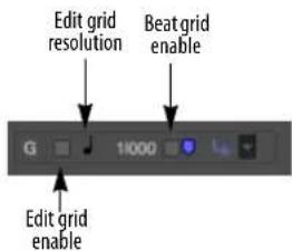
Figure 44-2: Waveform Editor edit grid.
EDIT LAYERS
Edit Layers (Figure 44-1 on page 526) allow you to edit, select, audition and otherwise manipulate waveform data, soundbites, stretch edits, sampler loops, volume data, beats and tempo maps in the audio file. Features specific to each edit layer are explained in detail later in this chapter.
A handy shortcut
Press Command/Ctrl-return to cycle through the edit layers.
TRANSPORT LOCK
The Transport Lock button in the Waveform Editor (Figure 44-1 on page 526) locks playback of the audio file displayed in the Waveform Editor window to Digital Performer's main transport controls. You can play, stop, rewind and otherwise control playback of the audio file displayed in the Waveform Editor using all of the familiar transport features in the Control Panel. In essence, the Waveform Editor acts like the currently enabled sequence (with regard to all transport-related features).
When you unlock the Transport Lock button, transport control returns to the currently play-enabled sequence.
Control Panel
When the Transport Lock button is engaged, all of the features in Digital Performer's main transport control panel, such as Memory Cycle, can be employed for Waveform Editor playback. In addition, all of Digital Performer's other playback-related features apply to the Waveform Editor. This includes:
■ "Auto scroll" on page 226
■ "Displaying the playback wiper" on page 227
■ "Click Preferences" on page 256
■ "Memory buttons" on page 206
■ "Displaying the playback wiper" on page 227
■ "Zooming with the wiper" on page 228
SELECTION
All of the features in the Selection Information window (“Selection Information” on page 359) can be applied to selection procedures in the Waveform Editor, including pre-roll, post roll and so on.
Additionally, you can click a channel label (to the left of the vertical amplitude ruler) to apply the current selection to only that channel.
GLOBAL TIME FORMAT
The global time format controls how time is displayed in the Waveform Editor. See “Time Formats window” on page 100. For example, if you wish to specify a selection by entering the start time and end time in samples, you can set the global time format to samples and then use the Selection Information window to type in the selection.
UNDO HISTORY
Each audio file has its own Undo History. To open its Undo History window, choose Edit menu > Undo History while the audio file is being displayed in the Waveform Editor and the Waveform Editor has the window focus. The audio file undo history allows you to take back changes you've made to the audio file. You can even remove individual destructive edits in the
undo history, without affecting other items in the history. For complete details, see “Undo History for audio files” on page 578.
THE AUDIO FILE OVERVIEW
As shown in Figure 44-1 on page 526, the narrow strip above the main waveform display provides an overview of the entire audio file.
The close-up lens
The close up lens in the overview represents the area of the audio file currently being displayed in the main portion of the Waveform Editor window as shown in Figure 44-1 on page 526. Drag the lens, or its edges, to change what is displayed. To view the entire file, drag the edges of the lens all the way left and right. (Or you can click the Zoom to fit button as shown in Figure 44-1.)
Making selections in the overview
The overview displays any current selections you have made in the main waveform display. You can also select any portion of the audio file in the overview itself, as long as it is outside the close-up lens.
Surround audio files in the overview
Surround audio files are displayed with all channels superimposed on top of one another.
THE AUDIO LAYER
As shown in Figure 44-1 on page 526, the audio edit layer lets you edit the audio waveform itself. The amplitude ruler on the left measures sample value from -1 to 1.
Editing deinterleaved audio files
When using deinterleaved audio, Digital Performer stores stereo audio in pairs of mono files, each with the same name and “.L” and “.R” in their names. Digital Performer sample-locks the files together, just as if they were interleaved, so that they always remain perfectly in phase with one another. The Waveform Editor has the ability to display and edit these stereo audio files, in effect treating them as if they are interleaved. Both channels of audio are displayed as a dual-waveform, which are selected and edited together (although you may also select either channel by itself, if you wish. See “Selecting with the I-Beam cursor” on page 534 for details.) In the overview, you have the choice of displaying both, one or the other, or both of them summed. See “Waveform Editor preferences” on page 544.
Likewise, Digital Performer stores deinterleaved surround audio files on disk as a group of mono audio files, each with the same name and appropriate file name (“.L” for left, “.R” for right, “.C” for center, “.Is” for left surround, “.Rs” for right surround, “.LFE”, etc.). Digital Performer sample-locks these files together, just as if they were interleaved, so they always remain perfectly in phase with one another.
Surround audio files display their channels separately in Digital Performer's waveform editor.
Editing surround files
The Waveform Editor provides full destructive waveform editing of the separate channels of a surround audio file. For example, you can use the Pencil tool on an individual surround channel to edit out a click or pop. The same is true for all other destructive edit operations, such as applying plug-in effects, cut/copy/paste operations, etc. To select individual channels, use the same keyboard shortcuts as for stereo files: Command/Ctrl-drag to select individual channels; Command/Ctrl-Shift-click to extend the selection. You can also Shift-click the channel name (in the amplitude ruler on the left edge of the window) to add or remove a channel from the current selection.
If you make a selection that includes one or two channels, you can use the New Audio File from Selection mini-menu command to make a new mono or stereo audio file.

Figure 44-3: The Waveform Editor provides complete destructive editing of surround audio files.
When copying and pasting portions of a surround audio file in the Waveform Editor, the source material in the clipboard must have the same number of channels as the paste destination, with the exception that mono-to-stereo and stereo-to-mono conversions are supported. See “Waveform Editor preferences” on page 544.
To apply Spectral Effects (Audio menu), such as formant-corrected pitch-shifting, to a surround audio file, all channels must be selected.
The Waveform Editor Time Rulers
The Waveform Editor can display time rulers in any of Digital Performer's four time formats: measures/beats, real time, SMPTE time code, and/or samples. You can show and hide any combination of these four rulers using the "Time Formats window" on page 100. The measure|beats|ticks ruler displays time according to the tempo map, if any, and the soundbite's sync point, if it has one. Below is a summary of how the measure ruler displays time in the Waveform Editor:
| Tempo map? Sync point? | Measure 1 placement | Time ruler display |
| No No At sample zero Follows a constant | tempo of 120 BPM | |
| Yes No At sample zero Follows the | tempo map | |
| No Yes At sync point | Follows a constant | tempo of 120 BPM |
| Yes Yes At sync point | Follows the | tempo map |
If a soundbite has no tempo map or sync point, the measure ruler places measure 1, beat 1 at sample number 0 and displays measures and beats based on a default tempo of 120 BPM. If the soundbite has a tempo map, the time ruler follows the tempo map. If the soundbite has a sync point, the time ruler places measure 1, beat 1 at the sync point.
Scrolling
You can, of course, use the horizontal and vertical scroll bars to move around in the file. You can also scroll horizontally by dragging the close-up lens in the overview as shown in Figure 44-1 on page 526. Here are some keyboard shortcuts for scrolling:
| Keyboard shortcut | What it does |
| Left/Right Arrow | Scrolls left or Right. |
| Up/Down Arrow | Scrolls up or down. |
| Page Up/Down | Scrolls up or down. |
| Home | Scrolls all the way up. |
| End | Scrolls all the way down. |
Zooming
The waveform display has very flexible zooming capabilities. You can zoom all the way out to see the entire audio file; conversely, you can zoom all the way in to make precise edits on individual samples, as demonstrated below in Figure 44-4.
Figure 44-4: The Waveform Editor can zoom in to the sample level. Zooming in this far makes it easy to make precise edits on individual samples.
Use the zoom controls shown in Figure 44-1 on page 526 to zoom the waveform:
- Click the +/- zoom buttons in the lower right corner to zoom horizontally or vertically. (Press on them continuously to zoom continuously.)
- Click the Zoom to Selection (magnifying glass) button in the lower right corner to fill the window with the current time range selection.
- Click the Zoom to Active soundbite button (soundbite icon) in the lower right corner to fill the window with the currently active soundbite (in the soundbite layer).
- Click the Zoom to File button (file icon) in the lower right corner to zoom back out all the way.
■ The Waveform zoom menu lets you zoom in on a smaller vertical range. Notice that the ruler scales with the waveform.
There are many additional ways to zoom the waveform display:
■ Drag over the waveform with the Zoom tool in the Tool palette
■ Drag in the time ruler with the Zoom tool to zoom in horizontally only
- Use the many commands in the View menu > Zoom sub-menu as explained in "Zooming" on page 331 and "Zoom menu shortcuts" on page 332.
SELECTING WITH THE I-BEAM CURSOR
To get the I-Beam cursor, click the Pointer tool in the Tool palette (Figure 44-1 on page 526).
Making selections with the I-Beam cursor
Dragging the I-Beam cursor in the waveform display or the overview makes a selection.
In a stereo or multichannel waveform, hold down the Command/Ctrl key to select just one channel.
Selecting by the numbers
Use the Selection Information window (“Selection Information” on page 359) to make precise, numerical selections.
Scrubbing while selecting
It is also possible to scrub while making selections. For details, see "Selecting while scrubbing" on page 536.
Summary of cursor selecting techniques
Here is a summary of the many techniques available in the waveform editor for selecting data:
To do this: Do this:
| Select a time range Drag with the I-Beam cursor. | |
| Select a time range in the overview | Drag with the arrow cursor. Note: you cannot start the selection inside the Close-up lens. |
| Extend the current selection Shift-click or Shift-drag. | |
| Select All Press command-A, or choose Select All from the Edit menu. | |
| Select a soundbite Make it active (see “Making a soundbite active” on page 536) and then double-click its title bar. | |
| Select a stereo waveform Use any of the techniques listed above. | |
| Select just one channel of a stereo waveform | Hold down the Command/Ctrl key while doing any of the selection techniques listed above. |
Extending the selection
As noted above, you can extend the current selection in either direction by Shift-clicking before it or after it. The Waveform Editor offers other shortcuts for extending the current selection in either direction by pressing keys on the computer keyboard.
To incrementally extend the selection:
Keyboard shortcut What it does
| Shift-Left Arrow, Shift-Right Arrow | Moves the right edge of the current selection forwards or backwards by a fixed number of samples.The number of samples is determined by the current zoom level. |
| Shift-Control-Left Arrow, Shift-Control-Right Arrow | Same as above, except that it moves the left edge of the current selection. |
Option/Alt key Use the Option/Alt key together with the above combination of keys to move by a smaller amount of samples.
Extending the selection using soundbite or loop boundaries
The Waveform Editor offers several similar key binding shortcuts for extending the current selection to surrounding soundbite and loop boundaries in the audio file. For details see "Soundbite and loop shortcuts" on page 541.
MAKING AN INSERTION POINT
Clicking the I-Beam tool (Figure 44-1 on page 526) gives you an insertion point, which determines where material on the clipboard can be pasted or spliced. It also determines where playback begins when you press Ctrl-spacebar to audition the audio file.
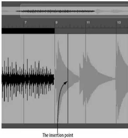
Figure 44-5: Click the I-beam cursor to place an insertion point. This can only be done in the waveform display, not the overview. Notice that the current insertion point location is displayed numerically in the Selection Information window.
The insertion point numerical display
The precise sample location of the insertion point is displayed in the Selection Information window (“Selection Information” on page 359).
Placing the insertion point in one channel
To place the insertion point in one channel of a stereo or surround audio file, Command/Ctrl-click. To extend the insertion point to another channel, Command/Ctrl-Shift-click.
AUDITIONING
The Waveform Editor provides many ways to audition the audio data.
Auditioning a selection
To audition any portion of the waveform, turn off Transport Lock and turn on Audible Mode, then make your selection; it will audition as soon as you release the mouse. If Audible mode is currently turned off, make your selection and then press Option/Alt-spacebar, or choose Audition Selection from the Region menu.
Auditioning from the insertion point
To audition starting at a specific point in the waveform, click it with the I-Beam cursor to place the insertion point. Then press Ctrl-spacebar to begin playing from the insertion point to the end of the file.
Stopping playback
At any time during auditioning, click anywhere to stop playback.
Loop auditioning
For details about the Audition Selection with Active Loop command and other loop auditioning commands, see “Auditioning the active sampler loop” on page 539.
SCRUBBING
To scrub audio forwards or backwards, click the Scrub tool in the Tool palette (Figure 44-1 on page 526) and drag left or right on the waveform.
If the Scrub tool grays out
The Scrub tool grays out when you are zoomed far enough in so that the rate of playback would be too slow to scrub. Choose View menu > Zoom > Zoom to Default Zoom (or use any other zooming technique you prefer to zoom out until the scrub button ungrays).
The Scrub tool also grays out if the MOTU Audio System is not currently active (MIDI Only is chosen in the Setup menu).
Scrubbing one channel of a stereo waveform
To scrub the left or right channel of a stereo waveform by itself, hold down the Command/Ctrl key while dragging with the scrub cursor.
Selecting while scrubbing
Hold down the Shift key while dragging with the scrub cursor to select what you are scrubbing or to extend the current selection while scrubbing.
Adjusting the volume for scrubbing
You can adjust the volume for scrubbing using the Audition volume preference. See “Audition volume” on page 95. Also see “Specifying audio output for auditioning” on page 338.
THE AUDIO LAYER MENU
The Audio edit layer menu can be accessed when you choose the Audio edit layer (Figure 44-1 on page 526). The commands in this menu alter the original waveform data.
Normalize
The Normalize command in the Audio edit layer menu (Figure 44-1 on page 526) boosts the level of the selected region by whatever amount is needed to make the loudest peak reach digital full scale (zero dB).
Fade In and Fade Out
To apply a linear fade in or fade out in the Waveform Editor, select the desired region and then choose Fade In or Fade Out from the Audio edit layer menu (Figure 44-1 on page 526).
In the Soundbites layer (chosen from the Edit Layer menu on Figure 44-1 on page 526), you can modify where soundbites start and end, a process referred to as soundbite trimming. In addition, you can perform many useful navigation and selection tasks.
Creating a soundbite in the Waveform Editor
To create a soundbite in the Waveform Editor, make a selection and choose New Soundbite from Selection from the Soundbite edit layer menu (Figure 44-1 on page 526).
Making a soundbite active
Before you can do anything to a soundbite in the Waveform Editor, you need to make it ‘active’ (so that Digital Performer knows which soundbite you wish to modify). When a soundbite is made
active, its borders become emphasized and it displays a title bar above it that shows its name, as shown below in Figure 44-6.

Figure 44-6: Before you can do anything to a soundbite, you need to make it active.
There are several ways to make a soundbite active:
■ Choose it from the Soundbite menu (Figure 44-1 on page 526).
■ Click its name in the Soundbites list.
- Choose the Soundbites edit layer from the Edit Layer menu (Figure 44-1 on page 526) and click the left or right edge of the soundbite with the cursor.
Trimming soundbites
To trim (move) the edge of a soundbite, make it active (as described above), and then grab the edge with the hand tool and drag it as desired. You can do this at any zoom level for any degree of precision you wish. You can also snap soundbite edges to beats, as explained in “Waveform Editor edit grid” on page 530.
Selecting the currently active soundbite
After you've made a soundbite active (as described in "Making a soundbite active" above), you can select the audio data in the soundbite by either of the following techniques:
■ Double-click the soundbite's title bar,
OR
■ Choose Set to Soundbite in the Selection Information section of the Information Bar.
Other soundbite-related selection techniques
You can double-click or triple-click as follows:
Do this To do this
| To select all the audio to the left orDouble-click the title bar area to right of the soundbite | the left or right of the soundbite title bar. |
| To select a single channel within aDouble-click the channel's stereo or n-channel soundbite | waveform anywhere inside the soundbite. |
| To select a single channel to the left or right of a stereo or n-channel soundbite |
| Double-click the channel's waveform to the left or right of the soundbite. |
| To select the entire audio file Triple-click the soundbite title bar. |
To select a single channel of a triple-click anywhere on the stereo or n-channel audio file for channel's waveform. the entire length of the audio file
Auditioning the active soundbite
There are several ways to audition the active soundbite:
■ Use the Audition Active Soundbite command in the Commands window.
- Select the audio in the active soundbite (as described above) and then audition it using any of the techniques described in “Auditioning” on page 535.
■ Choose Audition Active Soundbite in the Soundbite edit layer menu (Figure 44-1 on page 526).
Renaming the active soundbite
Option/Alt-click the soundbite's title bar to rename it.
Dragging and dropping a soundbite
To drag and drop a soundbite from the Waveform Editor into an audio track or other destination in Digital Performer, make it active and then drag it by its title bar to the desired window.
Sync points in the Waveform Editor
If a soundbite has a sync point (as described in "Sync points" on page 399), it will appear in the Waveform Editor. In soundbite mode, you can move the sync point.
The Soundbites edit layer menu can be accessed when you choose the Soundbites edit layer (Figure 44-1 on page 526) and offers several convenient features for working with soundbites.
Zooming to a soundbite
To fill the Waveform Editor window with the currently active soundbite, click the Zoom to Active Soundbite button (Figure 44-1 on page 526). This causes soundbite to fill the current space in the window.
Creating a soundbite from a selection
The Soundbite menu has an item that lets you create a new soundbite from any current selection. To do so, select any region (as explained in "Selecting with the I-Beam cursor" on page 534) and then choose New Soundbite from Selection from the Soundbite menu.
Deleting a soundbite
To delete a soundbite, make it active, and then choose Delete Active Soundbite from the Soundbite menu (Figure 44-1 on page 526). If the soundbite is being used in any track of any sequence in the project you currently have open, you'll see an alert dialog to warn you of this and confirm that you really want to delete it.
Be careful not to delete soundbites that you might still need for other projects (if the audio file is being used in other Digital Performer projects).
Auditioning a soundbite
To audition a soundbite, make it active and then choose Audition Active Soundbite from the Soundbite layer menu.
Setting the sync point for a soundbite
The Soundbite layer menu provides several commands for managing a soundbite's sync point:
Choose this To do this
| Set Sync Point At Insertion Point | To place the sync point at the current insertion point. 'The insertion point must be within the boundaries of the soundbite. If not, this command is grayed out. |
| Set Sync Point At First Beat | To place the sync point at the first beat within the soundbite, if any. |
Reset Sync Point To place it at the start of the soundbite.
THE LOOPS LAYER
In the Loops edit layer (chosen from the Edit Layer menu on Figure 44-1 on page 526), you can view, modify and otherwise manipulate sampler loops in the audio file currently being viewed in the Waveform Editor.
When you choose the Loops edit layer, the Loops edit layer menu appears to its right (Figure 44-1 on page 526).
Where sampler loops come from
Sampler loops may already exist in audio files that were imported into Digital Performer from a sampler or another program that supports file-based loops. You can also create them in the Waveform Editor (as explained in the next section).
Creating a sampler loop
To create a sampler loop, select the Loop tool in the Tool palette and drag over the waveform. Or make a selection and choose New Loop from Selection from the Loop menu. A loop is created out of the selection and given a default name of "Untitled".
Making a sampler loop active
In the Waveform Editor, Sampler loops work very much like soundbites. Before you can do anything to a sampler loop in the waveform editor, you need to make it ‘active’ (so that Digital Performer knows
which loop you wish to modify). When a loop is made active, its borders become emphasized and it displays a title bar above it that shows its name, just like the active soundbite shown in Figure 44-6.
To make a loop active, choose it from the list at the bottom of the Loop menu. Or click its edge with the finger cursor.
Renaming an active sampler loop
To rename a sampler loop, Option/Alt-click its title bar.
Trimming a sampler loop
To trim (move) the edge of a sampler loop, make it active (as described earlier), and then grab the edge with the hand tool and drag it. This works the same way as for soundbites. You can do this at any zoom level for any degree of precision you wish.
Selecting the currently active sampler loop
After you've made a sampler loop active (as described earlier), you can select the audio data in the loop by either of the following techniques:
■ Double-click the loop's title bar,
OR
- Choose Set selection to Active Loop in the Loop menu.
Auditioning the active sampler loop
The Waveform Editor lets you audition a loop, with or without playing any material just before or after the loop. Sometimes, you might just want to hear the loop itself, whereas other times you might want to hear some length of material leading up to the loop (i.e. the attack of a note), the loop itself (the sustain) and the material just after the loop (the release).
Either way, before you audition the loop, you'll want to choose how many times you'll hear it repeat. To do so, choose Set Loop Audition Options from the Loop menu and type in the number of repetitions, as shown below.
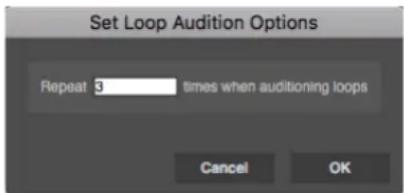
Figure 44-7: When auditioning a loop, use this feature in the Audition menu to determine the number of times the loop repeats.
To audition the loop just by itself, make it active (as described earlier), and then choose Audition Active Loop from the Loop menu (Figure 44-1 on page 526). Or you can select the audio in the active loop (as described in the previous section), and then audition it using any of the techniques described in “Auditioning” on page 535.
To audition the loop along with material before and after it:
1 Select the loop (as described in the previous section).
2 Shift-click with the I-Beam cursor to the left or right of the current selection to add preview time before and/or after the loop.
3 After you've selected the desired material before and/or after the loop, choose Audition Selection with Active Loop from the Loop menu.
Making a sampler loop from a soundbite
To make a sampler loop from a soundbite:
1 Select the soundbite. (See "Selecting the currently active soundbite" on page 537.)
2 Switch to loop mode.
3 Choose New Loop From Selection from the Loop menu.
THE LOOPS MENU
The Loops edit layer menu can be accessed when you choose the Loops edit layer (Figure 44-1 on page 526) and offers several convenient features for working with sampler loops.
Loop navigation shortcuts
Use the commands in the Loop menu as shortcuts for navigating the Waveform Editor. These commands either make a loop active, or they act on the currently active sampler loop. Most of the commands have keyboard shortcuts:
Loop menu item Keyboard shortcut
| Next Loop Command-Option-Right Bracket ( [ ) | |
| Previous Loop Command-Option-Left Bracket ( [ ) | |
| Scroll to Loop Start or End | Command/Ctrl-Option/Alt-B |
| Zoom to Loop (no default key binding) | |
| Set Selection to Active loop | (no default key binding) |
Audition Active Loop (no default key binding)
Jumping to the next/previous soundbite
The Next/Previous Loop commands in the Loop menu — and their respective key bindings — are a convenient way to quickly scroll to the various sampler loops in an audio file. After you've jumped to a loop, you can then use the other jump commands in the menu to inspect its edges or zoom in on its audio data.
Jumping to the boundaries of a sampler loop
The Scroll to Loop Start or End command in the Loop menu causes the waveform display to scroll to the beginning or end of the sampler loop. If you choose it again, it will jump to the other edge. This allows you to quickly jump back and forth between the beginning and end of the loop boundaries at any zoom level.
Zooming to a sampler loop
To fill the Waveform Editor window with the currently active sampler loop, choose Zoom to Loop. This makes the loop fill the current space in the window.
Creating a sampler loop from a selection
The Loop menu also has an item that lets you create a new sampler loop from any current selection. To do so, select any region (as explained in “Selecting with the I-Beam cursor” on page 534) and then choose New Loop from Selection from the Loop menu (Figure 44-1 on page 526).
Making a selection from a loop
The Loop menu also has an item that lets you set the selection to a sampler loop. Make the loop active and then choose Set Selection to Active Loop.
Deleting a sampler loop
To delete a loop, make it active, and then choose Delete Active Loop from the Loop menu (Figure 44-1 on page 526).
Setting the loop type
The Sound File Information window lets you choose the loop type for transfer to a sampler (loop forward, loop backward, etc.) See “The Audio Loop section” on page 367.
Transferring loops
When exporting a soundbite, its “Transfer in soundbite” item (Sound File Information window) for the loop needs to be enabled for that soundbite to include the loop in the new file. See “The Audio Loop section” on page 367.
SOUNDBITE AND LOOP SHORTCUTS
The following shortcuts are available for navigating through the soundbites and sampler loops in an audio file. These techniques move the insertion point, or the left or right edges of the current selection (if there is one):
Keyboard shortcut What it does
| Tab Moves the insertion point to thenextsoundbite or loop boundary. | |
| Option/Alt-Tab Moves the insertion point to theprevioussoundbite or loopboundary. | |
| Shift-Tab Moves the end | ____ of the currentselection to thenextsoundbite orloop boundary. |
| Shift-Option/Alt-Tab Moves the end | ____ of the currentselection to theprevioussoundbite or loop boundary. |
| Shift-Control/Win-Tab Moves the beginning____ of thecurrent selection to thenextsoundbite or loop boundary. | |
| Shift-Option-Control-TabShift-Alt-Win-Tab | Moves the beginning of thecurrent selection to theprevioussoundbite or loop boundary. |

Figure 44-8: If there is a current selection, you can move its edges to surrounding soundbite boundaries by pressing the Tab key along with the additional key bindings noted above.
THE PITCH LAYER
For details about using Pitch edit layer (Figure 44-1 on page 526) in the Waveform Editor, see chapter 81, "Transposing Audio" (page 935). When you choose the Pitch layer, the layer menu
lets you choose between Absolute and Relative pitch editing mode, as explained in “Absolute vs. relative pitch editing” on page 938.
THE BEATS LAYER
For details about using Beats edit layer (Figure 44-1 on page 526) in the Waveform Editor, see “Editing beats in the Waveform Editor” on page 684.
THE BEATS MENU
For details about using the Beats menu (Figure 44-1 on page 526) in the Waveform Editor, see “Beats menu” on page 685.
THE TEMPOS LAYER
For details about using the Tempos edit layer (Figure 52-8 on page 679) in the Waveform Editor, see "Viewing and editing soundbite tempo maps" on page 679.
THE TEMPOS MENU
For details about using the Tempos menu (Figure 44-1 on page 526) in the Waveform Editor, see “Tempo menu” on page 680.
THE STRETCH LAYER
For details about using the Stretch edit layer (Figure 44-1 on page 526) in the Waveform Editor, see “Stretching audio beats” on page 691.
THE BITE VOLUME LAYER
The Bite Volume edit layer (Figure 44-1 on page 526) provides breakpoint editing of a soundbite's Bite Volume curve, as shown below in Figure 44-9:

Figure 44-9: Breakpoint editing of Bite Volume.
For details about using the Bite Volume edit layer (Figure 44-1 on page 526) in the Waveform Editor, see “Soundbite volume automation” on page 407. Also see “Bite volume and gain” on page 650 and “Bite Gain” on page 393.
CREATING A NEW, EMPTY AUDIO FILE
To create a new, empty audio file, choose New
Audio File from the Waveform Editor mini-menu. The resulting sub-menu gives you a choices for creating a mono, stereo or surround file.
Digital Performer creates a new audio file that is half a second long. You can paste material into it of any length. Or you can lengthen it by copying the silence in it and pasting it multiple times.
CREATING A NEW AUDIO FILE FROM A SELECTION
At times, you may want to take a section of audio from an existing file and “export” it to its own, separate audio file. To do so, select the portion of audio you wish to export — or select a soundbite in the Soundbite list — and choose New Audio File from Selection in the Waveform Editor minimenu. If the command is grayed out, make sure the Audio edit layer is selected (Figure 44-1 on page 526).
If you want to create a soundbite from a selection, see “Creating a soundbite from a selection” on page 538.
EDIT MENU OPERATIONS
The following items in Digital Performer's main Edit menu can be used in the Waveform Editor:
- Cut
■ Copy
■ Paste
■ Erase
■ Merge
■ Snip
■ Splice
■ Undo/Redo
All of these commands work pretty much the same way as they do for MIDI and audio data in Digital Performer's other windows — except that they are destructive in the Waveform Editor. Also note the special considerations discussed in the following sections.
Cut, Copy, Erase and Snip
Just like you would expect, the Cut, Copy, Erase and Snip commands all require that you first select a region of audio on which to operate. Data is placed on the clipboard as usual. As in other windows, the Snip command actually removes the span of time covered by the selection.
Paste, Splice and Merge
As usual, these operations require two things:
AUDIO MATERIAL ON THE CLIPBOARD, AND
A LOCATION AT WHICH TO PASTE, SPLICE OR MERGE.
To place audio material on the clipboard, use the Cut, Copy or Snip commands.
To establish a location, you can either:
■ Make a selection
OR
■ Place the insertion point (Figure 44-5 on page 535)
In the case of a selection, the material on the clipboard is pasted, spliced or merged starting at the beginning of the current selection.
Merging in the Waveform Editor
In the Waveform Editor, the Merge command combines the audio data on the clipboard with any existing data in the audio file at the point where it is being merged. In other words, the audio data from the two sources is actually blended.
Undo/Redo
The Undo command in the Edit menu takes back your last action in the Waveform Editor. Redo puts it back. You can toggle between them as much as you want, until you do something else.
REGION AND AUDIO MENU OPERATIONS
The following sections discuss Region menu and Audio menu operations that can be used in the Waveform Editor.
Transpose
The Transpose command (Region menu) can be used on any selected region in the Waveform Editor. Just make a selection and choose Region menu>Transpose. Make sure that one of the two Transpose Audio... check boxes is checked in the dialog, depending on what you want to do. See "Transpose" on page 594 for details about these options.
Quantize and Groove Quantize
The Quantize command (Region menu) can be used on any selected region in the Waveform Editor. Use the Beats within Soundbites option, or any option that includes soundbite beats. For complete details, see “Quantizing beats within soundbites” on page 692. Also see “Groove Quantize” on page 609.
Scale Time
The Scale Time command in the Region menu can be used on any selected region in the Waveform Editor. Just make a selection and choose Region menu>Scale Time.
Spectral effects
The Spectral Effects command in the Audio menu, which applies Digital Performer's time stretching, pitch shifting and formant-shifting audio effects, can be used on any selected region in the Waveform Editor. Just make a selection and choose Audio menu>Spectral Effects.
Pitch and Stretch
The Pitch and Stretch sub-menu commands (Audio menu) apply to any pitch data that is within the current time range selection in the Waveform Editor. See “Pitch and Stretch” on page 650.
Applying MAS, VST and AU plug-ins
To apply any MOTU Audio System (MAS), VST, or Audio Unit (AU) plug-in, make a selection in the Waveform Editor, go to Audio menu>Plug-ins and choose the desired plug-in from the submenu. The effect is applied 'destructively' to the data in the audio file. You can undo it, but after you do something else, the change is permanent.
Beat and Tempo commands
All of the beat and tempo-related commands in the Audio menu can be applied to audio in the Waveform Editor (except for the commands that relate to matching the sequence tempo and
soundbite tempo). For complete details, see chapter 53, "Audio Beats and Tempo Detection" (page 681).
WAVEFORM EDITOR PREFERENCES
Choose Waveform Editor Preferences from the mini-menu to open them.

Figure 44-10: The Waveform Editor preferences.
Use crossfades on edits
When this check box is checked, Digital Performer applies an equal-gain crossfade at the border of every edit. As demonstrated below in Figure 44-11, if you cut a portion of audio, a crossfade is placed at the point where the cut is made — both at the beginning and end of the region.

Figure 44-11: In this example, when cutting audio, crossfades are applied as indicated by the arrows.
Choosing a crossfade length
You can also choose the length of the crossfades (in milliseconds) that are automatically applied during editing.
Suggestions for automatic crossfading
Crossfading on edits can be a huge time saver. But the degree to which you want to use it depends greatly on the material you are editing. For example, if you are editing the attacks of percussive hits, either turn off the automatic crossfading entirely, or apply very short crossfades (less than 10 milliseconds). Otherwise, the edits will take the “hit” out of the attacks. If you are editing sustained sounds, or complex audio material (multiple instruments, for example), you can edit freely with automatic crossfades and not have to worry about any undesirable artifacts. Your best bet is to audition the results of an edit the first time you start editing a certain type of material.
Be careful with crossfades when applying effects
Beware of crossfades when reversing audio or applying any other MAS, VST or AU plug-ins that might apply a strange transformation to your audio. For example, if you have crossfades turned on with a large fade size, and you choose the Reverse plug-in, it will reverse your audio, plus the
size of the crossfade area. However, the crossfade area may contain unwanted audio and then it will fade that area into the file. Here's a more specific example: if you recorded yourself saying "A B C D E F", then selected "C D" and reversed it, you may end up with audio that sounded a bit like "A Be D C bE F" (where lowercase letters represent faded audio). In some circumstances this behavior will lead to undesired crossfades. If you hear strange things at the boundaries of where you applied the audio effect, undo, turn off crossfades and try again. Or you could try making the fade time smaller.
Stereo/mono conversion settings
When the Use stereo/mono conversion option is unchecked, the Waveform Editor allows you paste mono material into a stereo file or vice versa.
When the Use stereo/mono conversion option is checked, the Waveform Editor allows you to paste mono material into a stereo file and, similarly, stereo material into a mono file. In addition, the Pan Settings option determines what happens in the conversion from mono to stereo (or vice versa). For example, if you paste mono material into a stereo file with the pan setting at pan center, the mono signal will be panned equally across both left and right channels. If it's panned hard left, however, the result when you paste is exactly that: the mono signal panned hard left within the stereo field.
The pan settings also affect what happens when pasting stereo into mono files. A hard left setting will mix just the left channel, for example.
CHAPTER 45 Selecting
OVERVIEW
Before you can edit anything in Digital Performer, you must first select it. Digital Performer provides many useful and powerful ways to make selections. After you've made a selection, you can apply Digital Performer's many powerful Edit menu and Region menu commands to whatever is selected.
This chapter shows you the many convenient ways to select data in Digital Performer. Except where noted, these techniques apply to any type of data (MIDI, audio, conductor track, automation, etc.)
Selection basics ....547
The View Filter....548
Choosing a Pointer tool selection mode ....548
Selecting events....549
Selecting a time range....551
Smart Selections ....556
SELECTION BASICS
There are three ways to make selections in Digital Performer:
■ Event selection — Selects specific events
■ Time range selection — Selects a region of time, regardless of what is in the region
■ Use the Search command to make selections based on time- and event-based search criteria
Selecting events
Event selection involves clicking (or dragging over) events in one Digital Performer's edit windows. The events become highlighted to indicate they are selected, and they can then be edited or otherwise modified.
Selecting a time range
A time range selection spans a certain period of time in one or more tracks, regardless of what data is in the region. In fact, time range selections can even be empty. For example, you could select four empty measures and actually copy them into the Clipboard — perhaps to splice the empty space somewhere in a track. Or, you could select two empty measures at the beginning of a track and then use the Snip command to remove them and move up everything else in the track to replace them.
Time range selections are always affected by Digital Performer's Smart Selections feature, which has an important impact on what happens when you make selections. So be sure to read “Smart’ Boundaries on Time Range Selections” on page 557.
Using the Search command
The Search command lets you select data by criteria—or rules—that you specify. For information about using the Search command, see chapter 46, “Searching” (page 561).
Edit operations that require time range selection
There are a few commands in the Edit menu and Region menu that require time range selection: Snip, Repeat, Paste Repeat, Merge Repeat and Retrograde. These commands wouldn't be able to do anything useful without a clearly defined end time for the selection, which event selections don't provide. Therefore, these commands are grayed out if the current selection is an event selection. To use them, make a time range selection as shown later on in "Selecting a time range" on page 551.
The 'Smart Selections' command affects time range selections
Digital Performer's Smart Selections command (Edit menu) has an important impact on edits that you apply to Time Range Selections. The effects are automatic, but you should definitely know about them so that you can use them to your benefit. For a summary, see “Smart Selections” on page 556.
Selections are global
After you have made any type of selection, the selection remains in effect until you either deselect or make another selection. The current selection appears in all edit windows. For example, if you highlight a few notes in a track's Event List, and then open the MIDI Editor for the same track, the notes will be highlighted in the MIDI Editor, too.
The current selection remains in effect even if you close all edit windows. So be careful not to inadvertently edit hidden data. Always be certain about what the current selection is before using Edit and Region menu operations.
Applying successive edits to the selection
Data remains selected even after you apply an edit operation to it. This lets you easily apply successive edits to the same data.
Auditioning the current selection
To play back the current selection, choose Audition Selection from the Region menu.
THE VIEW FILTER
In Digital Performer, if data is visible, it can be selected. Conversely, if it is hidden by the View Filter, it can be excluded from any selections you make. The View Filter can be a very fast and convenient way to include and exclude data by data type when making selections. For details, see "View Filter" on page 328.
CHOOSING A POINTER TOOL SELECTION MODE
Selection operations are made with either the Pointer tool or the I-Beam tool.
All selection operations made with the Pointer tool in the Track Overview or the Sequence Editor depend on the Cursor Selection mode (Preferences> Editing> Tools). These modes control what will happen when you use the Pointer tool to make selections in these multitrack windows.
'Event & Phrase Selections only' (lasso mode)
In this cursor selection mode, clicking in empty space makes a lasso selection (data only). Clicking on individual soundbites, MIDI notes, or data points (such as MIDI controllers or automation) selects them.
When dragging to make a selection, you can drag both horizontally and vertically so as to specify a specific time and value range. When you finish dragging to make your selection and let go of the mouse, only the events themselves remain selected; the time range is not selected.
■ Holding down the Control/Win key forces a lasso selection, even if you click a soundbite, unless the soundbite is selected, in which case you throw the soundbite.
■ Additionally, holding control will cause the selection to span the entire vertical range of the track (for example, to select all MIDI notes in a region without having to drag vertically over all of them).
■ Holding down the Control/Win and Option/Alt keys performs a time range (crosshair) selection.
'Range Selections only' mode
In this cursor selection mode, clicking anywhere except a selected soundbite or note performs a time range selection (with the crosshair cursor).
■ Holding the Control/Win key down allows you to make a range selection even when clicking on a selected soundbite or note. (To perform a throw operation you must hold the Control/Win key down after you click.)
■ Holding down the Control/Win and Option/Alt keys performs a lasso style selection.
'All Selections' mode
In this cursor selection mode, the Pointer tool is dynamic and will change depending on where it is positioned in the window. This mode gives you the most immediate flexibility for selection operations. Clicking on individual soundbites, MIDI notes or other events selects them. Moving the cursor over empty space turns the cursor into a cross hair and initiates a time range selection. Holding down the Control/Win key forces a time range selection, even if you click on a soundbite, unless the soundbite is already selected, in which case you throw the soundbite. Option/Alt-Control/Win-clicking performs a lasso-style (event) selection.
SELECTING EVENTS
The following sections explain how to select events. For time range selection techniques, see "Selecting a time range" on page 551. Also see "Edit operations that require time range selection" on page 547 to learn about a few commands in Digital Performer that can't be applied to event selections.
Event selections are not affected by the Smart Selections feature in the Edit menu, even when it is turned on. For more information, see “Smart Selections” on page 556.
Using the Pointer tool for event selection
The Pointer tool in the Tools palette (Studio menu) is used for event selections. Hold down the "a" key as a temporary shortcut for enabling the Pointer tool. Or double-tap the "a" key to permanently switch to the Pointer tool. With certain windows active, such as the Event List and the QuickScribe Editor, the Pointer tool is the only available tool.

Figure 45-1: Use the Pointer tool to make event selections.
Making an event selection in the Event List
To make an event selection in the Event List:
1 Open the Event List for the track.
2 Select the events you wish to change with the Pointer tool.
Below is a summary of how to select events in the Event List.
To select this Do this
| A single event Click on it. | |
| Several adjacent events Drag over the desired events. All events dragged over will highlight. | |
| Several non-adjacent events Hold down the Command/Ctrl key and click on the events you wish to select. They will highlight. | |
| Deselect events Hold down the Command/Ctrl key and click on the events you wish to deselect. They will unhighlight. | |
| Extend the currently selected region | Shift-click or Shift-drag at the desired end location. |
The specific events you select with the above techniques will become highlighted to show that they are selected. You can then apply any command from the Edit menu (except for Snip, Repeat, and Retrograde. For details about these commands, see “Edit operations that require time range selection” on page 547).

Figure 45-2: An example of an event selection, shown here in the Event List.
Making an event selection in the MIDI Editor
There are a number of techniques for selecting individual MIDI events in the MIDI Editor. For complete information, see “Selecting Notes” on page 420 in the MIDI Editor chapter. Many of these techniques apply to event selection in other edit windows: Sequence Editor, Drum Editor, etc.
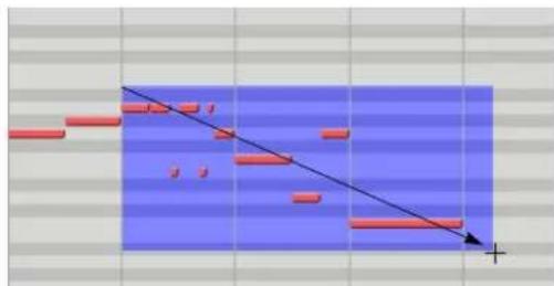
natural_image
Abstract diagram with red rectangular blocks and a diagonal line, no text or symbols presentFigure 45-3: Making an event selection (notes, in this case) in the MIDI Editor.
Making an event selection in the QuickScribe Editor
For information about selecting notes in the QuickScribe Editor, see "Selecting notes for editing" on page 496.
Making an event selection in the Track Overview
This section explains how to make event selections using the Track Overview. Also see “Selecting a time range in the Track Overview” on page 552. Event selection in the Track Overview is affected by the Cursor Selection mode setting (Preferences> Editing> Tools). For details, see "Choosing a Pointer tool selection mode" on page 548.
To make an event selection in the Track Overview:
1 Choose the Pointer tool in the Tools palette (or, as a shortcut, double-tap the "a" key).
2 Place the cursor in the middle of a data phrase "block" so that the cursor turns into an arrow (instead of a cross-hair).
Be sure you use the arrow cursor. The cross-hair cursor is for selecting a time range (see the next section).
If the arrow cursor does not appear, make sure that the Cursor Selection Mode (Preferences> Editing> Tools) is set to either Event & Phrase Selections Only or All Selections.

flowchart
graph TD
A["Start"] --> B["Process Step 1"]
B --> C["Process Step 2"]
C --> D["End"]
style A fill:#f9f,stroke:#333
style D fill:#bbf,stroke:#333
Figure 45-4: Put the cursor over the very center of a data block to produce the arrow cursor shown here.
3 Click the phrase with the arrow cursor to select it.
The events displayed inside the phrase becomes selected, showing a gold highlight and outline. This is similar to selecting the events in the Event List. In fact, if you open the track's Event List, you'll see the events highlighted in the list.
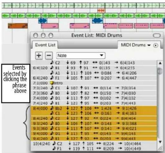
Figure 45-5: Clicking a block in the Track Overview with the arrow cursor as shown here produces an event selection. If you look in the track's Event List, you'll see the selected events, also shown.
Making an event selection in the Sequence Editor
Use the Pointer tool to make event selections in the Sequence Editor. Be sure that the Cursor Selection Mode (Preferences>Editing>Tools) is set to either Event & Phrase Selections Only or All Selections.
1 Choose the Pointer tool in the Tools palette (or, as a shortcut, double-tap the "a" key).
2 Place the cursor over the item you wish to select so that the cursor turns into an arrow or a pointing finger.
3 Click the event to select it.
SELECTING A TIME RANGE
The following topics show you the many ways to select a time range. For event selection techniques, see “Selecting events” on page 549.
Time range selections are affected by Digital Performer's Smart Selections feature, which has an important impact on what happens when you make selections. See “Smart Selections” on page 556 for more information. Time range selections in the Sequence Editor are affected by the edit grid, if enabled. For details, see "Snap to Grid" on page 355 and the edit grid controls in Figure 38-1 on page 372.
Selecting a time range in the Selection Information window
This method of time range selection allows you to make a selection containing any combination of tracks. It lets you specify the region numerically, which gives you a high degree of precision. It works with all Edit menu and Region menu commands.
1 Open the Selection Info window (Studio menu).
2 Enter the desired start and end times.
3 Select the track or tracks that contain the region.
To learn track selection techniques, see "Selecting tracks" on page 180.
You now have a time range selection that includes all of the tracks you highlighted. Notice that the Track Overview reflects the selection as well, as does the Sequence Editor and other the edit windows of the selected tracks.
The Event List and QuickScribe Editor allow event selection only
The QuickScribe Editor does not provide for time range selections because it uses non-linear, engraver spacing to display MIDI events as music notation. Therefore, the Pointer tool can be used to make “marquee” selections over notes and other events (text, etc.) on the page.
The Event list provides a list of events, with no graphic representation of time, so it allows for event selection only using the Pointer tool.
Using the Pointer and I-Beam tools to make time range selections in graphic editors
The Pointer and I-Beam tools in the Tools palette (Studio menu) can both be used to make time range selections in graphic editors, as explained in the following sections.

Figure 45-8: Use the Pointer tool and I-Beam tools make time range selections.
Selecting a time range in the MIDI Editor and Drum Editor
To select a time range in the MIDI Editor or Drum Editor, drag horizontally in the Time Ruler with either the I-Beam tool or the pointer (which turns into an I-Beam in the ruler).
You can also drag across the note grid or continuous data grid with the I-Beam tool.
Selecting a time range in the Track Overview
Both the I-Beam tool and the Pointer tool can be used to make time range selections in the Track Overview. The I-Beam tool restricts time range selections to one track at a time, whereas the Pointer tool lets you select across several tracks in one operation.
Time range selections with the I-Beam tool
The I-Beam tool is ideal for “surgical” selection operations in the Track Overview, such as selecting tracks that are not adjacent to one another. As you drag the I-Beam tool to make a time range selection, it constrains the operation to a single track. You can then Shift-click other tracks above and below the selected region to add them to the selection.
Time range selections with the Pointer tool
All selection operations made with the Pointer tool in the Track Overview depend on the Cursor Selection mode (Preferences>Editing>Tools). For
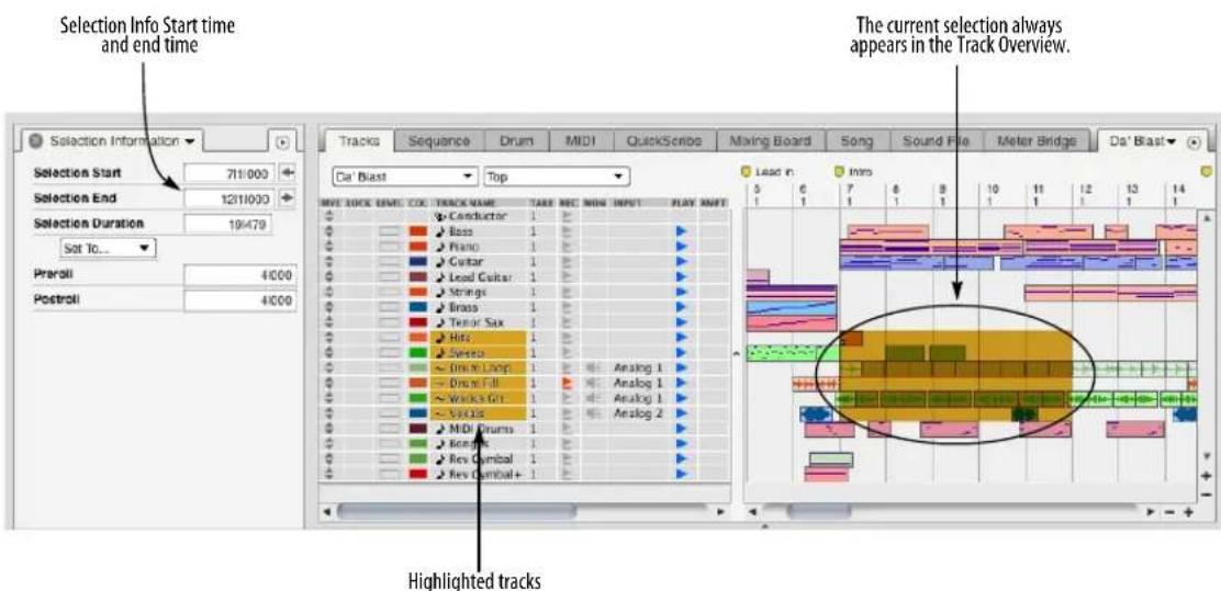
Figure 45-6: Figure 45-7 When you make a time range selection using the Track List (by selecting tracks and setting the selection start and end times), the selection appears as a highlighted region in the Track Overview.
example, you can choose Range Selections Only mode, which produces a cross-hair cursor anywhere in the Track Overview. For complete details, see “Choosing a Pointer tool selection mode” on page 548.
Below are some further details about making time range selections in All Selections mode:
Placing the cursor over an empty portion of the grid always produces a cross-hair, which makes a time range selection when you drag.

Placing the cursor over the center of a block produces an arrow cursor, which creates an event selection when you click.

You can get the cross hair cursor (for a time range selection) over data blocks by moving the cursor near the edge of the block.
Figure 45-9: Selection cursors in the Track Overview.
Folder selections
In the Tracks Overview, a time range selection can be made in collapsed or expanded folders, making a selection across all of the tracks in the folder. The selected data can then be copied, pasted, and otherwise edited like any other selection.
In the Tracks List, selecting the folder name selects all of the tracks in the folder.
The Edit Tracks in Closed Folders option, found in the Tracks Window's mini-menu in previous versions of Digital Performer, has been removed. If you make a selection which includes a
closed folder but do not wish to edit a folder's contents, deselect the folder by Command/Ctrl-clicking its name in the Tracks List.
Tracks Overview selection summary
Below is a summary of time range selection techniques in the Track Overview:
To accomplish this Do this
To get a cross-hair cursor over a Move the cursor to the top or block of data bottom edge of the block.
To select a single measure (or a single column segment at any other zoom level)
Click it with the cross-hair.

To select several adjacent measures (or column segments at any other zoom level)
Drag over them with the cross-hair cursor — diagonally if the segments are in several adjacent tracks.
To select non-adjacent measures Shift-click and/or Shift-drag over (or column segments at any other zoom level) them with the cross-hair cursor.
To add or remove measures from Shift-click and/or Shift-drag over the current selection them with the cross-hair cursor. (or column segments at any other zoom level)
To quickly select a single Click in the Time Ruler above the measure in all tracks (or a single column. column at any other zoom level)
To select any time range in all tracks Drag in the Time Ruler.
To select any time range without "snapping" to columns Use the Command/Ctrl key along with any of the techniques mentioned above.
To select everything between twoClick the first marker in the time markers ruler.
To select everything between the Click either the punch-in or punch-auto-record punch in/out points out arrow marker in the time ruler. or the Memory Cycle repeat bars
To deselect all current selections Click in the area below the overview or press Command/Ctrl-D.
Selecting a time range in the Sequence Editor
Many of the same techniques just discussed for making time range selections in the Track Overview also apply to the Sequence Editor.
For example, the I-Beam cursor selects one track at a time; shift click the I-Beam tool above or below a current selection to add that track to the selection. To remove a track from the current selection, Shift-click the track name.

Figure 45-10: Using the I-Beam tool to select non-adjacent tracks.
The selection modes (“Choosing a Pointer tool selection mode” on page 548) apply to Pointer tool selections, giving you quick access to a variety of selection techniques via a dynamically changing cursor. For example, to select a soundbite, click near its (vertical) center with the pointer cursor. To initiate a time range selection in the middle of a soundbite, move the pointer to the bottom edge, where it turns into a cross hair.
Time Ruler selection techniques
There are several time-saving techniques for selecting data in the Time Ruler in the Track Overview, Sequence Editor, MIDI Editor, and Notation Editor:
- Drag horizontally in the lower half of the Time ruler with the I-Beam cursor. Shift-click to extend the selection. (If Snap to Grid is turned on, dragging will "snap" to the Edit Resolution grid.)

- Click one of the Memory Cycle markers (to select the time range between them).

- Click the Auto Record punch-in or punch-out marker (to select the time range between them).

- Click any marker in the Track Overview (to select the time range between it and the next marker).

Initiating time range selections with an insertion point
If you click the I-Beam tool anywhere in any graphic editor, an insertion point appears:

Figure 45-11: The insertion point in the Sequence Editor.
The insertion point can be placed in the Track Overview, Sequence Editor, MIDI Editor, Notation Editor and Drum Editor.
In the Track Overview, click in a column to place the insertion point at the column just to the right of where you click, or Command/Ctrl-click to place it anywhere:

Figure 45-12: In the Track Overview, click the I-Beam cursor to place the insertion point at the column just to the right of where you click. Or you can Command/Ctrl-click to place it anywhere.
There are numerous keyboard shortcuts for controlling the placement of the insertion point, as shown below in Figure 45-13.
After you've placed the insertion point, you can use it as a starting point for making and extending a selection, by Shift-clicking and other selection modification techniques, including the keyboard shortcuts discussed in the next section.
Modifying a time-range selection using the computer keyboard
The Commands window (Setup menu) has a large selection of shortcuts for manipulating selections. These commands can be used in the Tracks Overview, Sequence Editor, MIDI Editor, Notation Editor and Drum Editor.
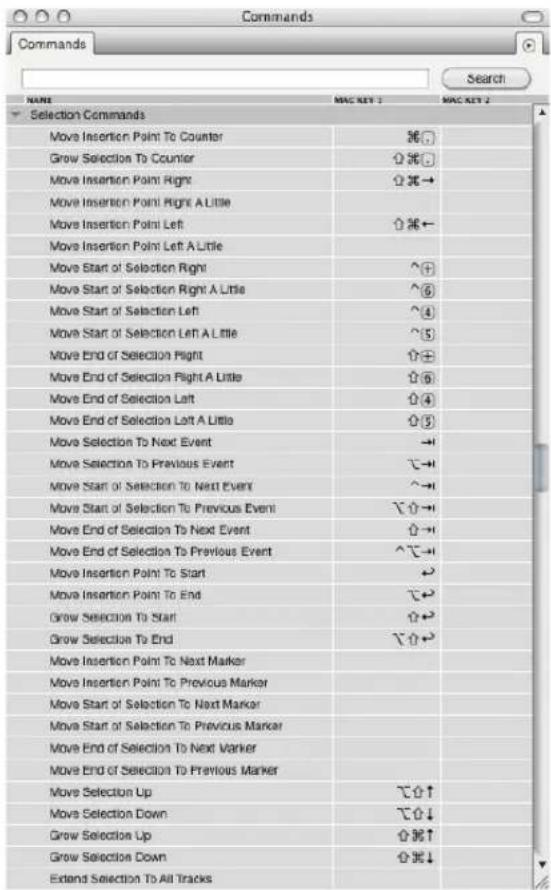
Figure 45-13: selection commands.
Modifying a time-range selection using the mouse
Shift-click (or Shift-drag) near the edge of the selection you want to adjust.
Listening to the current selection
To listen to the currently selected region, press Ctrl-spacebar or Option/Alt-click the Audible mode button. Doing so causes the selected region to play in its entirety.
The 'Remember Times' command
The Remember Times command (control-R), allows you to save a time range selection, so that you can load it into the Selection bar later on. You can also load remembered times into the Memory Bar and the Auto-Record Bar.
To use Remember Times:
1 Make any selection.
2 Press Control-R.
The start and end time of the current selection is stored by Remember Times.
To load the Remember Times into the Selection Bar, Memory Bar, or Auto-Record Bar, use the "Set to Remembered Times" command under the Selection, Memory, or Auto-Record menus.
SMART SELECTIONS
The Smart Selections command in the Edit menu is a checkable menu item that can be either turned on (checked) or off (unchecked). When it is turned off, it has no effect on selections. When it is turned on, it affects Time Range Selections. (For an explanation of what a Time Range selection is, see "Selection basics" on page 547.)
What does the Smart Selections command do when it is turned on? Generally speaking, it makes Time Range selecting and editing operations give you results that are more musical and intuitive. In a way, turning on Smart Selections is like telling Digital Performer, "Do what I mean, not what I say."
Digital Performer accomplishes this “musical intelligence” in a combination of separate, but related, ways. Below is a summary of Smart Selection features, followed by several sections explaining each feature in further detail.
- “Smart boundaries” on time range selections — this means that events that are a few ticks before or after the selection boundaries are either included or excluded, depending on what makes sense musically.
■ Measure-relative pasting — allows you to place the playback wiper (or main counter) anywhere in the measure you want to paste into and data will be pasted at its original location within the measure. With Smart Selection turned off, data would be pasted at the exact tick location displayed in Digital Performer's main counter.
■ Controller and pitch bend effects are maintained when cutting and pasting — this means that when controller and pitch bend data is added to or removed from a track via time range selection copying and pasting, Digital Performer maintains the effect of the controllers before and after the selected region by automatically generating and inserting new controller events into the track as needed.
■ Barline placement is preserved when cutting and pasting in the Conductor track — allows you to freely cut, copy, and paste time range selections in the conductor track, even when it has lots of meter changes in it, without barlines getting out of alignment with existing music in the tracks.
'Smart' Boundaries on Time Range Selections
If the Smart Selections command in the Edit menu is checked, Digital Performer automatically allows for a bit of musically determined "slop" before and after the boundaries of a time range selection to account for notes and other events that occur a few ticks on either side of the selected region's boundaries (as shown in Figure 45-14 on page 558). If Smart Selections is turned off, the selection bar start and end times are hard and fast — an event that is even 1 tick outside the region is not included.
If you want precision, turn Smart Selections off. If you want musical results without fussing with details, turn Smart Selections on.
Smart Selection must be turned on or off as desired before you make a selection. Turning it on or off does not affect current selections. The Smart Selections feature affects all of the Time Range selection methods discussed in this chapter; it has no effect on event selections.
Measure relative pasting
In general, when you paste, Digital Performer pastes at the location currently displayed in the main counter (and also indicated by the playback wiper in windows that have it) — along with one additional condition: if Digital Performer's Smart Selections feature is turned off, material is pasted at the exact tick location shown in the counter. If Smart Selections is turned on, material is pasted measure relative, which means that it is placed in the measure at its original location within the measure, so that you don't have to worry about exact placement of the counter, as shown below. Just get the counter anywhere into the measure you want and paste.

Figure 45-15: Measure relative pasting is a great convenience when you are working fast.

Figure 45-14: An example of how the Smart Selections feature affects time range selections.
Pitch bend and controller effects are preserved
Whenever you insert a controller or pitch bend event into a track, it affects all notes after it for the rest of the track — or until the next controller in the track. Similarly, when you cut and paste pitch bend or controllers, you are removing from or adding them to the track, which will have an impact on all notes after the cut or paste area.
When Smart Selections is turned on, however, Digital Performer preserves all pitch bend and controller values after the cut or paste region, automatically adding pitch bend or controller events after the edit region as necessary to do so, as shown in Figure 45-16.
The end result is that you will never be surprised: the portion of the track after your edits will always sound the same as it did before your edits.
Barlines are preserved in the Conductor track
If Smart Selections is turned off, cutting and pasting time regions in the Conductor Track can get tricky — especially if you have meter changes

in the area you are editing. For example, if you cut a meter change, you may find that barlines after the removed meter change are no longer correctly aligned with the notes they are supposed to be aligned with.
Smart Selections takes care of problems like these by making sure that meter changes you introduce by cutting or pasting will preserve subsequent measures and meter changes in the Conductor Track to ensure that nothing gets out of alignment by mistake. If you are cutting and pasting the Conductor Track, be sure to turn on Smart Selections.
CHAPTER 46 Searching
OVERVIEW
Digital Performer's Search command provides you with a powerful, flexible way to locate and select data. You can select the data you find or display it in the Search Results window, which lets you browse it, select it, open its Event List, or even export it to an HTML file.
You can base your searches on as many search criteria as you like, making them as simple or elaborate as you want. You can also base your searches on the chosen attributes of currently selected data.
You can name and save search settings for later use.
You can conduct multiple successive searches to add or subtract to the current selection.
Search window Quick Reference....561
Search window mini-menu....562
Basics 562
Working with search settings....564
The time-related search settings.....566
The event-related search settings.....567
Working with search results ....568
Basing settings on the current selection .....570
The Search Results window....570
SEARCH WINDOW QUICK REFERENCE
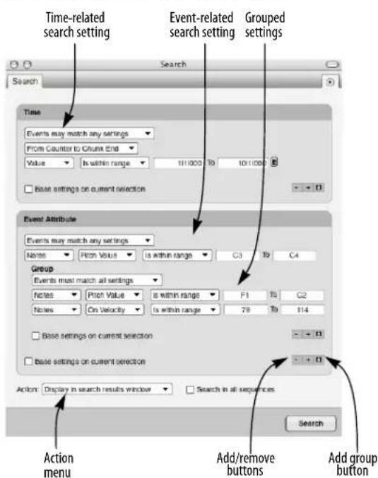
Figure 46-1: Digital Performer's Search window.
Time-related search setting: Lets you specify time-related criteria for your search, such as a range of time within the tracks being searched, and/or the metrical position of data within each measure being searched.
Event-related search setting: Lets you search for specific types of data, such as notes or pitch bend. You can even search for specific data characteristics, such as note-on velocity values or hex strings inside SysEx messages. You can also search for Digital Performer-generated events, such as tempo changes, key changes, meter changes and markers.
Grouped settings: Lets you specify two or more search criteria that are to be considered together as a whole.
Add/remove buttons (+/-): The plus-sign button adds a new time- or event-related search setting to the bottom of its group. The minus-sign button removes the bottom setting (or group) from the group.
Add group button ([ ]): Adds a new group of settings, nested within the current group. You can then use the +/- buttons within the new group to add and remove criteria within the group.
Action menu: Lets you choose what to do with the search results.
'Base settings on current selection' option:
Causes Digital Performer to look at the currently selected data for search settings. This option only affects the settings in its particular group.
SEARCH WINDOW MINI-MENU
New search: Clears the Search window of all current search settings and restores it to its default state, ready for you to enter new search settings.
Save search settings: Lets you name and save the current search settings in the Search window for later recall from the mini-menu.
Edit search settings: Opens a dialog that lets you rename, delete, re-order and assign a keyboard shortcut to saved search settings.
Restore default search settings: Puts the factory default search settings back in the Search window mini-menu (and the Search sub-menu in the Edit menu).
BASICS
The Search command is found in the Edit window mini-menu, and it provides a hierarchical sub-menu with several other search-related commands. The sub-menu also displays search settings you have created and saved.
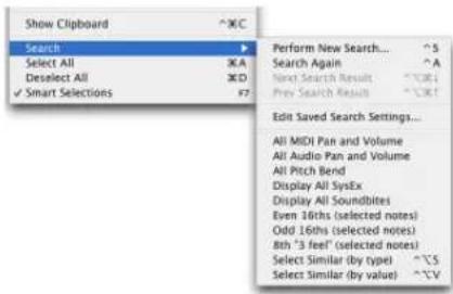
Figure 46-2: The search command sub-menu.
When searching, you need to choose where to search and what to search for. The Search Command lets you specify both to an extremely high degree of detail—as much detail as you like. There is no inherent limit to the number of criteria you can use when searching—except perhaps the maximum number of search settings that will fit on your computer screen in the Search window.
Searches can be simple. For example, you might want to search for all notes in a track between G#3 and F4. Searches can also be elaborate and detailed. For example, you might want to search for all notes between measures 10 and 20 that fall directly on downbeats and are between C2 and G3 with on-velocities between 80 and 110 and with durations greater than or equal to 240 ticks.
The Search window, which you open by choosing Search>Perform New Search from the Edit menu, lets you specify the search settings (as shown in Figure 46-1 on page 561). It also lets you choose whether to select the data or display the results of the search in the Search Results window.
If you choose to select the search results, you can then apply any Digital Performer Edit menu or Region menu command to the selection.
If you choose to view the outcome of your search in the Search Results window, you can browse the selected data in one convenient list. You can select any portion of the results. You can go to the data in its editing window. You can even export the contents of the Search Results window as an HTML file for printing or importing into a word processor programs or any other software that can import the file.
Overview of how to perform a new search
This section gives you the basic procedure for conducting a search. Each step is discussed in detail in the sections that follow.
To perform a new search:
1 Decide where you want to search.
There are several things you can do to control where Digital Performer searches, and they are discussed in detail in the next section. In most situations, the Search command will search in the top-most open edit window. So if you want to search in more than one track, bring the Tracks window to the front and select the tracks in which you want to search. If you only want to search in one track, bring one of its edit windows to the front.
2 Open the Search window by choosing Search>Perform New Search from the Edit menu.

Figure 46-3: Performing a new search.
3 Make your time- and event-related search settings.
Add new search settings with the plus buttons. Add a group with the “[ ]” button. To remove the bottom setting in a group, use the minus button.
4 To determine what Digital Performer will do with the results of the search, choose the desired Action from the Action menu.
5 Click the Search button.
If you chose to select the search results, data found by the search will become selected. If you chose to display the found data in the Search Results window, it will appear.
You can leave the Search window (and Search Results window) open to refine your search or conduct as many further searches as you want.
Choosing where to search
There are several factors that control where Digital Performer will conduct the search:
THE SEARCH IN ALL SEQUENCES CHECK BOX OPTION IN THE SEARCH WINDOW, IF CHECKED.
THE TOP-MOST WINDOW BEHIND THE SEARCH WINDOW.
THE TIME-RELATED SEARCH SETTINGS YOU'VE CHOSEN.
THE ACTION YOU CHOSEN TO TAKE.
These factors are listed in order of precedence. Number 1 takes precedence over number 2, and so on. For example, if the Search in all sequences option is checked, it won't matter what the top-most window is.
Here's another example: let's say you have selected some data in a bass track, and you've chosen to search within the range of the current selection as shown below in Figure 46-4. But the piano track is the top-most window at the time you click the Search button. Even though the selection is in the bass track, the search will actually be conducted in the piano track because it is the topmost window. The selection in the bass track does, however, determine the time range of the search in the piano track.

Figure 46-4: Digital Performer always searches in the top-most window behind the Search window — unless the 'Search all sequences' option is checked. In this example, the selection in the trumpet track determines the range of time for the search, but the actual search occurs in the string ensemble track, since its Event List is the top-most window.
Here's an example of how the Action option you choose in the Search window can affect the results of the search. Let's say that in the example above, the Action you've chosen is Select subset of current selection. In this case, nothing will happen as a result of the search because there is no current selection in the piano track.
WORKING WITH SEARCH SETTINGS
The Search window's search settings give you a great deal of control over your searches. The sections below will help you get the most out of them.
Adding/removing search settings
As you can see in Figure 46-1 on page 561, Search settings are always grouped into sections in the Search window (as prescribed by the outline boxes around them). Each group has Add (+), Remove (-), and Add group ([]) buttons that let you add and remove individual search settings, as well as groups of settings, to and from the group. New items are always added at the end of the group. The Remove button always removes the item at the end of the group. If you need to remove an item in the middle of a group, you'll have to delete the ones below it, too, and then re-add them again afterwards.


Figure 46-5: Adding search settings. If you start with Example A above and click the Add (+) button to the Event Attribute group four times, you'll then have four new search settings as shown in Example B. You can then adjust the newly added settings as desired. Also notice the 'Events may match any settings' option.
Adding/removing a group
As discussed above, groups are added and removed like other settings with the “[ ]” and Remove (-) buttons, respectively. You can add as many groups as you want, and you can nest groups within each other (discussed later).
Matching settings within a group
When two or more search settings are present in a group, an additional menu appears at the top of the group. The menu has two possible settings:
■ Events may match any settings
■ Events must match all settings
When you choose Events may match any settings, the Search command will find an event as long as it matches at least one of the settings in the group. It only has to match one of the settings in the group to be included.
When you choose Events must match all settings, the Search command will include an event in the search results only if it matches all of the settings in the group. In the example below, the only notes that will be found by the search are ones whose pitch is between C3 and C4 AND whose on-velocity is less than 64 AND whose duration is less than 1|000.

Figure 46-6: Grouping search settings. In this example, only notes that match all the settings will be found by the search. Combining groups with other settings/groups
Grouping can be a powerful tool for finding exactly what you are looking for in your searches. When you use the Events must match all settings option in a group, you are basically making the group act as a single unit in qualifying data for the search. In other words, when you combine it with other individual search settings within its enclosing group — or even other groups — it will following the same logic as if it were an individual setting.
Controlling search logic with groups
Grouping can be used to create logical distinctions between search settings. Consider the following example. Let's say you wanted to find all notes that are out of range for a certain instrument. So you enter the settings shown below.

But now lets say that you wanted to further restrict the above search to notes with a duration less than 1 beat. If you just added a duration setting without grouping, as shown below, you would not get the result you want because the duration setting would select any notes with a duration less than 1 beat, not just ones above C4 and below C1.

You would not be able to fix this problem by changing the Events may match any settings option to Events must match all settings because you would end up with a invalid search: you'd be searching for notes that are both above C4 and below C1 at the same time — an impossibility.
By grouping the settings as shown below, however, you set up a search logic that is exactly what you want:
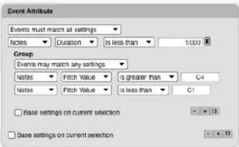
As you can see, this setup is like saying "I want all notes whose durations are less than 1 beat AND whose pitch is EITHER above C4 OR below C1."
Nesting grouped settings
Groups of settings can be nested as deeply as you need to achieve the search logic you want, as shown below in Figure 46-7. Just remember: to make the group act as a whole (e.g. all of the settings within the group must be met before data will be included in the search result), use the Events must match all settings option for the group. If you want the events in the group to be considered individually, use the Events may match any settings option.
In case you are wondering, Figure 46-7 will find events between measures 10-20 only that fall on the 1st, 2nd, 3rd, 5th, 6th or 7th eighth-note of the measure. In addition, the data must be a note between C3 and C4 with an on-velocity greater than 80, or it can be a controller #55 with a value less than 10 or greater than 90.


Figure 46-7: Nested search settings.
THE TIME-RELATED SEARCH SETTINGS
Digital Performer lets you specify the location of what you are looking for by any combination of the following time-related search settings:
All time
All time means that the search will look from the beginning to the end of sequence.
Metric grid
Metric grid lets you specify events by their position within an evenly-spaced grid. For example, you could choose only data that falls on the eighth-note offbeat of the first and third beats of each measure being searched. The grid spacing is set up similar to the way you would specify a quantize grid in Digital Performer: choose a note duration that defines the grid with the controls provided (shown in Figure 46-8). In addition, Digital Performer uses its Smart Quantize engine when determining if events fall on a grid point, so the metric grid works even on unquantized data.
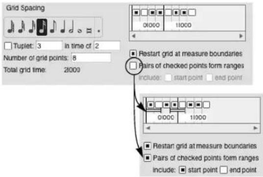
Figure 46-8: Searching using a metric grid.
The search command offers several additional options. The Number of grid points lets you restrict the grid to a limited size that repeats itself over the range of the search. This lets you apply the grid to each measure individually, or even several measures at a time. The Restart grid at measure boundaries option does exactly what it says, regardless of how long the grid is. The Pairs of checked points form ranges option creates ranges of time instead of individual grid points. This feature is very powerful because it lets you specify individual ranges of time of any size at any resolution. You can choose to either include or exclude the start and end points of the ranges.
Value
The Value setting allows you to choose specific time in which to search. Further choices are shown below. The Is (with slop) option is notable because it lets you specify a specific time with a little bit of “give and take” before and after the time you specify. You can choose the amount of “slop”.

Selection range
The Selection range setting lets you specify a range of time by the current selection. Make sure you select a time range — or some data — before you use this option.
The counter and chunk start/end settings
The From Counter to Chunk End and From Chunk Start to Counter options let you specify a range of time using the current time in Digital Performer's main counter and the beginning or end of the current sequence.
THE EVENT-RELATED SEARCH SETTINGS
The event attribute settings let you search by data type (such as notes) and by the specific parameters of each data type (like note-on velocities). You can further specify value ranges of a data attribute (velocities between 80 and 100, for example) or qualities of a given attribute (e.g. a key signature with 3 flats).

Figure 46-9: Event types you can search for.
If you just want to search for several types of events, regardless of their specific parameters, you can use the Event Type>Choose option as shown below:

If you need to further restrict your search to certain attributes of a data type, then choose it by name from the list shown above in Figure 46-9, and then you'll also have access to all of the attributes that type of data. An example is shown below.
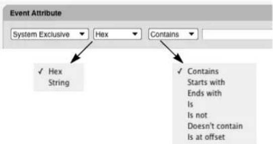
Figure 46-10: The event attributes for SysEx data.
A few notes on SysEx searches
When searching for hex data within SysEx messages, do not include the F0 or F7 as part of the search string.
When you are using the Is at offset option shown in Figure 46-10, offset zero is the first byte past the F0 at the beginning of the message.
WORKING WITH SEARCH RESULTS
After you set up the search settings the way you want, as described on the preceding pages, use the Action option at the bottom of the Search window to determine what will happen to the results of the search. The Action options are shown below and are self-explanatory:

Figure 46-11: Choose what to do with the results of your search with the Action option.
Be careful when you are using the Select subset of current selection option. The top-most window behind the Search window must have a selection for this option to do anything. For example, let's say that you have a selection in the Tracks window over several tracks, but the piano track is not included in the selection. If the Event List for the piano track is the top-most window when you click the Search button, nothing will happen. The current selection will remain unchanged, and there will be no selection made in the piano track. On the other hand, if you have a selection in the piano track, the Search command will create a subset of it (if it finds data within the selection that meets the search criteria).
Searching again
The Search Again command in the Edit menu (located in the Search sub-menu) re-applies the last search you conducted. The settings used are the ones that were in the Search window at the time you clicked the Search button — not the settings that are currently in the window. On the other hand, if you’ve changed the topmost window — or any other factor that affects where the search takes place, the Search Again command applies the search to the new situation. For example, if the last search you conducted was over the entire
sequence, but you now have a single track's Event List open as the topmost window, the Search Again command will search that track.
Searching again in exactly the same area
The Refresh command in the Search Results window mini-menu (explained later) lets you reapply the exact same search, even if you've change the top-most window or any other factor that affects where searching takes place. For details, see "Searching again with the Refresh command" on page 571.
Performing multiple successive searches
By leaving the Search window and Search Results window open, you can perform multiple successive searches. You can also use the Select subset of current selection and Add to current selection options with successive searches to add and subtract from the current selection. By doing so, you can create a selection as elaborate as you wish.
Next/Previous Search Results
The Next Search Result and Previous Search Result commands in the Edit menu (located in the Search sub-menu) browse through the current search results in the editing window for their track. This is similar to clicking the Previous/Next Search Result buttons in the Search Results window (as shown in Figure 46-14 on page 570).
Saving & editing search settings
The Search window mini-menu has several commands that let you name, save, edit, rename and delete search settings that you create. When you name and save a set of search settings, you are capturing all of the settings visible in the Search window at the time you save it.

Figure 46-12: To save the search settings currently shown in the Search window, choose Save Search Settings from the Search window mini-menu.

Figure 46-13: the Edit Search Settings command in the Search window mini-menu lets you rename and delete search settings, as well as assign a keyboard shortcut to them. This command is also available in the Search sub-menu in Digital Performer's main Edit menu.
To assign a keyboard shortcut to a saved search setting:
1 Choose Edit Search Settings from the Search window mini-menu (or from the Search submenu in the Edit menu).
2 Click on the dash to the right of its name.
3 Press the desired keyboard shortcut.
4 Click anywhere outside the text box.
Restoring default search settings
Digital Performer ships with a collection of useful search presets, which appear in the Search window mini-menu, as well as in the Search sub-menu in the Edit menu. If you accidentally modify or delete some of these default search settings, you can restore them with the Restore default Search
Settings command in the Search window mini-menu. Any custom search settings you have created and saved will not be modified in any way by this operation—as long as they have names that are different from the factory default search settings.
BASING SETTINGS ON THE CURRENT SELECTION
Each group of settings in the Search window has an option called Base settings on current selection. When you check this option, the values for any settings in the group are taken from the current selection, if any. If there is no selection, they are ignored. In general, when you check this option, the settings that are taken from the current selection are displayed differently to indicate that the information is being taken from the current selection. For example, the option might gray out, or it might be displayed as a “----” instead of a text box.
There are some settings that are not taken from the current selection when this option is checked — in useful ways. For example, if you are using the Time>Is (with slop) setting as shown below, the time itself will be taken from the current selection, but the amount of slop is not. This allows you to search on various time locations with the same amount of slop each time.

THE SEARCH RESULTS WINDOW
To open the Search Results window, choose Display in search results window from the Action menu in the Search window and click the Search button.

Figure 46-14: The Search Results window.
Search Results window quick reference
Search results list: Displays the data found by the last search operation.
Select button: Selects the events currently highlighted in the Search Results window list. Unlike the Go button, this command does not open editing windows or the Tracks window. Instead, it just selects the data.
Go button: Opens the editing window and selects the data for the currently highlighted data in the Search Results window list. If events from more than one track are currently highlighted, the Go button opens the Tracks window (or brings it to the front) and selects the highlighted data.
Previous/Next search result buttons: Does the same thing as the Go button for the next or previous item in the Search Results window list.
Search Results mini-menu quick reference
Refresh: Performs the exact same search as the very last time you clicked the Search button in the Search window, even if you've since changed the top-most window, the selection being searched, or any other aspect of the search that can affect where it takes place.
Export: Opens a standard file save dialog box, which lets you save the current contents of the Search Results window as an HTML file.
Group: Some search settings, like the metric grid, naturally clump events into groups. If you use such a setting in your search, it will appear by name, such as Metric grid 1, as a checkable item in this sub menu. When you check it, you'll be able to select grouped items in the Search Results list as a group by clicking on just one of them.
Search Results window basics
The Search Window appears when you choose Display in search results window from the Action menu in the Search window and then click the Search button.
Like the Search window, the Search Results window can stay open as you perform multiple searches.
Data listed in the Search Results window can't be edited, as this window is only meant for browsing. You can, however, highlight data in the list. After data is highlighted, you can either select it with the Select button, or select it and open its edit window with the Go button. If data from more than one track is highlighted when you click Go, it will select all of the data and open the Tracks window instead (or bring it to the front if it is already open).
The Previous/Next Search Result buttons, as shown in Figure 46-14 on page 570, do the same thing as the Go button for the next or previously highlighted item in the list.
Searching again with the Refresh command
Often, you'll conduct a search and then make changes to your data based on the search. You might then realize that you want to conduct the same search again. But since you've been working in many different windows, changing the current selection, and otherwise changing the conditions under which the original search was conducted, you can't just click the Search button again because you won't get the same results.
The Refresh command in the Search Results window mini-menu fixes this problem by conducting the exact same search again, regardless of whether the factors that control where the search takes place have changed.
Exporting search results as text
The Export command in the Search Results window mini-menu lets you export the list in the window as an HTML file for printing or importing into a word processor programs or any other software that can import the file.
Grouping search results
Some search criteria, such as the metric grid, find clusters of events that you might like to highlight, select, and view as a whole. The Group item in the Search Results window mini-menu lets you do so. Simply check the search criteria you'd like to group the search results by. For example, if you've used a metric grid in your search, choose it by name — something like “Metric Grid 1” — from the Group sub-menu. Now, when you click on an event in the Search Results list that belongs to a cluster of events found by the metric grid search setting, all of the events in the cluster will highlight. Similarly,
if you click Go, they'll all be highlighted in the Event List that opens for them. The same goes for the Previous/Next Search Results arrow buttons.
CHAPTER 47 Edit Menu
OVERVIEW
For a general explanation of how to use Edit menu operations, see chapter 34, “Editing Basics” (page 325). All Edit menu commands can be applied to MIDI data, audio data or both:
Undo....573
Redo ....573
Redo Next/Select Branch ....574
Undo History....574
Cut....580
Copy 580
Copy to Clipping window....581
Paste....581
Paste Multiple....582
Paste Repeat ....582
Paste Repeat Multiple ....582
Other Paste commands....582
Erase....582
Duplicate....582
Repeat 583
Merge....583
Merge Multiple....584
Merge Together ....584
Merge Repeat ....584
Merge Repeat Multiple....584
Merge Repeat Together....584
Other Merge commands....584
Snip....585
Splice....585
Splice Multiple....585
Other Splice commands ....585
Shift....585
Layering....587
Continuous Data ....587
Heal Separation ....587
Split....588
Split Audio ....588
Split at Counter....588
Trim....589
Trim Audio....589
Trim End / Trim Start 589
Show/Hide Clipboard 590
Search 590
Select All....590
Select All in Range 590
Deselect All ....591
Smart Selections....591
UNDO
The Undo command will undo the effects of most commands and actions that add, delete, move, or otherwise modify data. Undo will also undo the effects of both real-time and step recording. Undo is unlimited. This means that if you invoke it repeatedly, you can essentially step backwards through your previous actions. For example, if you choose Undo three times, you'll go back three actions. Undo can be used together with Redo to step forwards and backwards through your document's Undo History. For further details, see "Undo History" on page 574.
REDO
The Redo command restores the action that was just undone. Like Undo, Redo is also unlimited. This means you can restore undone actions until you reach the most recent action you've taken in your project.
Together, Undo and Redo allow you to step repeatedly backwards and forwards through the project's current history of actions (the “Undo History” on page 574).
Both Undo and Redo give you a brief description of the action they are undoing or restoring, such as Undo drag note or Redo paste into track 'Lead Guitar'.
REDO NEXT/SELECT BRANCH
The Redo Next/Select Branch command is very similar to Redo Next Action: it lets you move forward through the project's current history of actions. But it also lets you choose a different path when you come to a point in the undo history where there is a branch, rather than simply stepping past the branch along the main branch. Branching is explained in more detail in the next section.
UNDO HISTORY
Digital Performer supports unlimited Undo/Redo. It can remember everything you have ever done to a project, even after you close and quit, across any number of sessions, all the way back to the moment the project was first created. The Undo History window provides a complete log of actions and numerous features for navigating through the undo history and jumping to any point. Unlimited branching is supported (explained later), and an undo time line is also provided. 'Pruning preferences' allow you to control how far back actions are remembered and how much disk space the undo history will take up. Digital Performer also saves a permanent undo history for audio files, allowing you to undo any changes that have been made at any time since the audio file was first created.
How unlimited undo works
Digital Performer keeps track of every significant action you take in a project from the moment you first create the project. The undo history is permanent and never discarded—unless you choose to do so.
The same is true for audio files, which also have their own individual, permanent undo history that stores every action done to the audio file since it was first created. The history is never discarded and instead is saved in the same folder as the audio file itself. Each audio file has its own undo history. Audio file undo histories have an additional feature: they allow you to remove — or even modify — steps in the middle of the history, in essence letting you “rewrite history”.
POLAR sessions also have their own Undo History window, although the POLAR session undo history is discarded when you close the session.
Summary of Undo commands in the Edit menu
The Edit menu has the following Undo-related commands:
| Command: | Defaultkey binding: What it does: | |
| Undo [action] Mac: | Command-ZWin:Ctrl-Alt-Z | Undoes the last action. |
| Redo [action] Mac: | Shift-Command-ZWin:Ctrl-Shift-Z | Restores what has just been undone. |
| Redo Next/Select Branch | Mac:Option-Shift-Command-ZWin:(None) | Goes one step forward in the Undo History, and lets you specify which branch, if there are more than one at that step. |
The Undo History window
The project Undo History window (Edit menu) shows a complete log of actions taken since a project was first created. Each action taken appears as a line of information in the list, including its name (a brief description of the action), the time it occurred, the amount of memory (RAM) it takes to remember it, and the amount of disk space, if any, required to keep it as an action that can be undone later. Disk space only applies to actions that require disk space to begin with (such as recording). For example, if you record 20 MB of audio data, and then undo the record pass, the record pass item stored in the undo history takes 20 MB of disk space. Background processing tasks are displayed in
italic text in the Undo History window list. If you would like to undo a background task, double-click it.
The Now column
The Now column, on the very left of the history window, displays a dot next to the most recent action taken or redone. It truly is “now” in the sense that its location represents the current state of the document. Double-click this column next to any action to immediately jump to that point in the undo history. You could work for three days, on and off, and still go all the way back to the state you were in at the beginning of the project by double-clicking next to the item at the very top of the undo history list.
Actions that have been undone are displayed with a blue highlight. To redo (jump to) an undone action, double-click the Now column to the left of its name.
The Undo history time line
The Time column in the undo history list gives you the exact time at which each action was taken. The time line at the top of the window provides a linear representation of the undo history. The
Time of Day strip provides a time reference. Drag it left or right to move backwards or forwards in time. Zoom buttons are provided to the left. The current action marker is represented as a green vertical line. This marker corresponds to the current action dot in the Now column. To move the current action marker, move the current action dot as explained in the previous section.
The Editing strip just below Time of Day displays individual actions as small vertical lines. The white area represents the elapsed time from the beginning of the session up to the most recent action. To go to a particular location in the time line and identify the actions there, you can click directly on the action lines in this strip to highlight them, both in the strip itself and in the undo history list below. The list will provide all of the details.
Here's a zooming shortcut for the undo time line: click on the Editing strip and drag vertically. Drag down to zoom in and drag up to zoom out.

Figure 47-1: The project Undo History window (Edit menu).
Branching
A branch occurs when you jump backwards in the undo history and then embark on a new set of actions. At this point, you have two branches: the original set of actions (now undone) and the new set of actions. Digital Performer remembers both sets of actions, called branches, and allows you to return to any point in either branch.
Here's an example. Let's say that you are starting a new project. You record some drums. Then you record some bass. Then you record some lead guitar. But after attempting a few passes of lead guitar, you realize that none of them are good, and in fact, you need to edit the bass part before going any further. So you jump back in the undo history window to the last bass guitar record pass and begin editing the bass track.
At this point, the Undo History window would look something like this, with a branch after the last bass record pass, followed by the bass edits below the branch:

Figure 47-2: An undo history branch. The actions currently shown (and not undone) are the "main branch" or "main trunk".
The lead guitar passes constitute a branch that is stored in the branch menu shown in Figure 47-2. They are represented in the menu by the first action of the branch, Record on Track 'Lead Guitar'. To continue with our example, if you now decide to discard your bass track edits and restore the lead guitar passes recorded earlier, you would view the lead guitar branch (by choosing it from the branch menu) and then double-click in the Now column next to the last action in that branch as shown below in Figure 47-3:
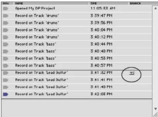
Figure 47-3: To view a different branch, choose it from the branch menu. To jump to that branch, double-click the Now column next to the action you wish to restore.
At this point, all of your bass track edits have been undone and are stored in the branch menu. All of the lead guitar passes have been restored. In other words, when you jump from one branch to another, the actions in the branch you leave are all undone.
Viewing one branch at a time
Notice that in Figure 47-2 and Figure 47-3, the View menu is set to One Branch at a Time. This means that the actions in the list represent one branch, or what we refer to as the main trunk. The main trunk is the set of actions that got the project to the state that it is currently in. All branches leading off of the main trunk are stored in branch menus like the one shown in Figure 47-3. You could simply ignore the branch menus and use the rest of the undo history features as described.
Viewing all branches at once
To view all branches at once, choose All branches at once from the view menu. With this option chosen, our previous example looks like this:
| NAME | TIME | BRANCH |
| Opened My DP Project | 11:05:33 AM | |
| Record on Track 'drums' | 3:39:47 PM | |
| Record on Track 'drums' | 3:39:56 PM | |
| Record on Track 'drums' | 3:40:04 PM | |
| Record on Track 'drums' | 3:40:12 PM | |
| Record on Track 'bass' | 3:40:44 PM | |
| Record on Track 'bass' | 3:40:48 PM | |
| Record on Track 'bass' | 3:40:53 PM | |
| Record on Track 'bass' | 3:40:57 PM | |
| Record on Track 'Lead Guitar' | 3:41:32 PM | |
| Record on Track 'Lead Guitar' | 3:41:41 PM | |
| Record on Track 'Lead Guitar' | 3:41:48 PM | |
| Record on Track 'Lead Guitar' | 3:42:03 PM | |
| Edge Edit Soundbite 'bass-6' | 3:47:18 PM | |
| Drag Events in Sequence 'Seq-1' | 3:47:23 PM | |
| Drag Events in Sequence 'Seq-1' | 4:12:45 PM | |
| Drag Events in Sequence 'Seq-1' | 4:12:48 PM | |
| Edge Edit Soundbites | 4:12:53 PM | |
| Edge Edit Soundbite 'bass-6' | 4:13:05 PM |
Figure 47-4: Viewing all branches at once. In this example, you can see both the 'lead guitar' branch and the 'bass edit' branch below it, which is currently undone (shaded blue).
In this view, all actions in all branches are shown in the list, with each branch separated by heavy lines. This view is not strictly chronological; instead, actions are grouped by branch. (Actions will always be listed chronologically within a branch.) In addition, there may be sections of undone actions (branches), interspersed with actions that are not undone and that constitute the current main trunk (as you'd see if you went back to viewing just one branch at a time). In our ongoing example, if we stepped back through (undid) two of our lead guitar record passes and then made another branch by editing the lead guitar track, the result would look like this:
| NAME | TIME | BRANCH |
| Opened My DP Project | 11:05:33 AM | |
| Record on Track 'drums' | 3:39.47 PM | |
| Record on Track 'drums' | 3:39.56 PM | |
| Record on Track 'drums' | 3:40.04 PM | |
| Record on Track 'drums' | 3:40.12 PM | |
| Record on Track 'bass' | 3:40.44 PM | |
| Record on Track 'bass' | 3:40.48 PM | |
| Record on Track 'bass' | 3:40.53 PM | |
| Record on Track 'bass' | 3:40.57 PM | |
| Record on Track 'Lead Guitar' | 3:41.32 PM | |
| Record on Track 'Lead Guitar' | 3:41.41 PM | |
| Record on Track 'Lead Guitar' | 3:41.48 PM | |
| Record on Track 'Lead Guitar' | 3:42.03 PM | |
| Drag Events in Sequence 'Seq-1' | 4:55.03 PM | |
| Edge Edit Soundbite 'Lead Guitar-8' | 4:55.06 PM | |
| Edit Fade in Track 'Lead Guitar' | 4:55.08 PM | |
| Edge Edit Soundbite 'bass-6' | 3:47.18 PM | |
| Drag Events in Sequence 'Seq-1' | 3:47.23 PM | |
| Drag Events in Sequence 'Seq-1' | 4:12.45 PM | |
| Drag Events in Sequence 'Seq-1' | 4:12.48 PM | |
| Edge Edit Soundbites | 4:12.53 PM | |
| Edge Edit Soundbite 'bass-6' | 4:13.05 PM |
Figure 47-5: By undoing two of our lead guitar record passes, and then doing some edits on the guitar track, we create a third branch. The bass track edits are still visible as their own branch at the bottom of the list.
If we viewed Figure 47-5 as one branch only, it would appear as follows:

Figure 47-6: Viewing the current example (in Figure 47-5) as one branch. The first branch menu contains the bass track edits made early on in our example. The second branch menu contains the two lead guitar passes that we just recently undid before the lead guitar track edits.
Undo history and branching is unlimited
Digital Performer records an unlimited number of branches and actions in the Undo History window. How much it can remember is limited only by the amount of RAM and disk space in your computer.
Pruning preferences
The undo history has the potential to take up large amounts of memory and disk space, depending on the type of work you are doing. In addition, you may find that you rarely go back in time more than, say, about an hour as you work. For circumstances like these, Digital Performer can discard — or “prune” — branches according to rules that you specify and that accommodate your work style and needs. Click the Pruning Preferences button to open these preferences as shown below:

Figure 47-7: Pruning preferences.
The Prune entries when there are more than _ entries option lets you limit the number of undo history entries to any number that you specify from the menu provided. When an undo entry moves back in the history further than this limit, it is permanently discarded.
The Prune Entries taking up more than option applies to all actions, both on the main trunk and in all branches. This option can be useful during recording sessions, in which you are likely to generate and discard large amounts of audio data. But if you are the type of person who often
searches back for takes you recorded way back at the beginning of your sessions, use this option with caution!
The Prune Entries on branches option only applies to actions that are in branches and are therefore undone. In other words, they are actions that are not on the path that you took to get to the project in its current state (the main trunk). Often, these types of actions are much less likely to be revisited, so you can be more aggressive about pruning them.
The last option, When Audio recording try to keep..., forces the undo history to flush items when disk space gets low. It starts with actions farthest back in the history and works its way forward as needed. What you choose here depends largely on how much disk space your system provides, and the manner in which you record.
Undo History for POLAR sessions
POLAR sessions have their own Undo History window, which you can open by clicking the History button in the POLAR window itself. POLAR session Undo Histories work the same way as project Undo Histories, except that they are not saved. Instead, they are discarded when the POLAR session is closed.
Undo History for audio files
Each audio file has its own Undo History window. To open it, click the Open Undo History button in the audio file's Waveform Editor.

Figure 47-8: Opening the Undo History for an audio file.
This window functions identically to the project Undo History window. The Undo History for each audio file is saved with the file.
Audio file undo histories provide an additional feature: not only can you jump backwards in the history to any action, you can also modify or remove an action without affecting what comes after it in the history. For example, if you applied some EQ to an audio file, but three months later decide that you'd like to change the EQ settings, just double-click the EQ action item in the Undo History list to open the plug-in window or Spectral Effects window to modify the settings and reapply them. This works for plug-ins and spectral effects that have been applied to the audio file. To remove the action entirely, click its name to highlight it and choose Erase from the Edit menu or press the delete key. Modifications to actions in the undo history itself are not undoable, except by manually restoring them.
Undo histories for audio files are saved in the same folder as the audio file itself. To maintain the Undo History, do not separate the audio file and its undo history folder. Also, don't rename the undo history folder.
Audio file and POLAR Pruning Preferences
The Undo Pruning Preferences (Figure 47-7) provide separate preferences for audio file and POLAR undo histories:

Figure 47-9: Pruning preferences for audio files and POLAR.
Manually flushing the undo history
While the Undo History Pruning setup automatically flushes items from the undo history based on your criteria, Digital Performer also provides several ways to manually flush (empty) the Undo History for a Digital Performer project, a POLAR session or an audio file.
The most comprehensive way to flush the undo history is to use the Compact Project command (see “Compacting an entire project” on page 60).
The Undo History window mini-menu provides a set of commands for flushing the undo history in various ways:
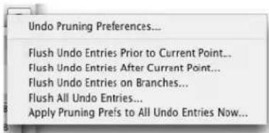
Figure 47-10: The Undo History window mini-menu.
These commands are present in the Commands window, as shown below in Figure 47-11:
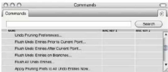
Figure 47-11: Use these commands to flush the undo history manually.
The Flush Undo Entries Prior to Current Point command gets rid of all undo entries before the current location of the dot in the Now column (as explained in “The Now column” on page 575). The Flush Undo Entries After Current Point command gets rid of all entries after the current location dot. The Flush Undo Entries on Branches command gets rid of all undo actions on any branches that are not part of the main branch. In other words, it gets rid of all actions that are not part of the branch that leads up to the document’s current state. The Flush All Undo Entries clears the entire Undo History log. The Apply Pruning Prefs to All Undo Entries Now clears the undo history according to your current pruning preferences, except that it ignores the time attribute. So, if your current preference setting reads “Prune entries taking up more than 10 MB on disk, that have not been visited in the last 2 hours”, it will flush all entries larger than 10 MB for all time.
Choosing which undo history to flush manually
As explained earlier, there are three different types of undo histories in a project: the project undo history, the POLAR session undo history, and audio file undo histories. The manual flush commands (Figure 47-11) apply to the front-most window as follows:
If an undo history window is in front, the undo flush commands are applied to that history.
If the POLAR window is in front, the undo flush commands are applied to the undo history for the POLAR session that is currently loaded in the POLAR window.
If the Soundbites window is in front, the undo flush commands are applied to the undo histories of the parent audio files of any currently selected soundbites. In addition, only the Flush All Undo Entries and Apply Pruning Preferences commands work on selected soundbites in the Soundbite list. To use the other commands on a specific audio file's undo history, just open its undo history window.
If none of the windows just mentioned are in front, then the flush commands apply to the project's undo history.
CUT
The Cut command removes data in the selected region and places it on the Clipboard. This does not remove the time region specified; instead, it leaves the measures blank (silent). The type of information that is cut is determined by the View Filter. The Cut command is undoable.
Before measure 3 is cut:

After measure 3 is cut: (The length of the music is the same.)


COPY
The Copy command copies the data from the selected region and places it on the Clipboard. The original data is not affected at all. The type of information that is copied is determined by the View Filter. The Copy command is undoable.
Before measure 3 is copied:


After measure 3 is copied:
(The length of the music is the same.)


COPY TO CLIPPING WINDOW
The Copy to Clipping Window command places the current selected data into the clipping window that you choose from the sub-menu as a single clipping. For details, see chapter 55, “Clippings” (page 705).
PASTE
The Paste command inserts the contents of the Clipboard (i.e. whatever was most recently cut or copied) into a track at the location that you specify. When you paste, you need to tell Digital Performer where you want the Clipboard data to go. Digital Performer needs to know:
■ What track (or tracks)
■ What time in the track (or tracks)
Choosing a track (or tracks) to paste into
To choose the track you want to paste into, you can either open an event edit window for the track (see “Opening an edit window for a track” on page 181) or click the track’s name in the Tracks window or Sequence Editor to highlight it. To paste into several tracks at once, highlight their names (see “Selecting tracks for editing” on page 180).
If you are pasting into the MIDI Editor, and it is currently displaying multiple tracks (and there is no currently selected data), data will be pasted into the displayed track that is highest in the track list (and the track selector list).
Indicating the time at which you want to paste
There are several useful ways to choose the time at which you want to paste:
■ If there is already a current selection in any track, Digital Performer will use the beginning of the selection (either the first event of an event selection or the start time of a time range selection) to determine where it pastes.
- If there is no current selection, Digital Performer pastes into the measure currently displayed in the main counter (and also indicated by the playback wiper in windows that have it) — along with one additional condition: if Digital Performer's Smart Selections feature is turned off, material is pasted at the exact tick location shown in the counter. If Smart Selections is turned on, material is pasted measure relative, which means that it is placed in the measure at its original location within the measure so that you don't have to worry about exact placement of the counter. Just get the counter anywhere into the measure you want and paste. For more information, see “Smart Selections” on page 556.
Choosing tracks and location at the same time
You can use any of the selection techniques in the Track Overview to choose the track and the location at which you want to paste with one easy selection. See “Making an event selection in the Track Overview” on page 550 and “Selecting a time range in the Track Overview” on page 552.
What happens when you paste
The length of the pasted region is exactly that of the data in the Clipboard (including any blank space at the beginning and end of the region that was placed on the Clipboard).
Pasting data always replaces what was previously there — unless you have temporarily hidden it with the View Filter. The types of information pasted from the Clipboard are determined by the View Filter. In addition, only the types of data
selected in the View Filter are replaced; all other data is unaffected. The Paste command is undoable.
Measure 3 from Track-1 is copied into the clipboard:

Track-2 before measure 3 is pasted:

Track-2 after measure 3 is pasted:

PASTE MULTIPLE
This variation of the Paste command can be accessed by holding down the Option/Alt key while accessing the Edit menu. Paste Multiple allows you to paste data from a single track into multiple tracks in a single operation. For example, if you copied track A, and you wish to paste it into tracks X, Y and Z, select tracks X, Y and Z, hold down the Option/Alt key, and then choose Paste Multiple from the Edit menu.
PASTE REPEAT
The Paste Repeat command fills the current time range selection with the contents of the clipboard, repeating the clipboard data to fill up the selection. For example, if you would like to fill a section of a track with material on the clipboard, repeating it as many times as necessary to fill the section, just make a time range selection over the section and choose Paste Repeat. In cases like this, Paste Repeat is more convenient than the Repeat command because you don't have to figure out how many times to repeat the data. Paste Repeat fills the selection for you, automatically repeating the data as many times as necessary.
PASTE REPEAT MULTIPLE
This variation of the Paste Repeat command can be accessed by holding down the Option/Alt key while accessing the Edit menu. Paste Repeat Multiple allows you to paste data from a single track into multiple tracks in a single operation. For example, if you copied data from track A, and you wish to paste repeat the data into tracks X, Y and Z, select tracks X, Y and Z, hold down the Option/Alt key, and choose Paste Repeat Multiple from the Edit menu.
OTHER PASTE COMMANDS
Several additional variations on the Paste command can be found in the Commands window (Figure 9-1 on page 105). If you search the Commands list for the word Paste, you can find them and assign your own custom keystrokes to them. Included are Paste At Wiper, Paste At Wiper Multiple, Paste At Original Time, and Paste At Original Time Multiple.
ERASE
The Erase command works like the Cut command except that no data is put on the Clipboard: all data in the selected region is removed and the region is left blank. The types of data erased are determined by the View Filter setting. The Erase command is undoable.
Before measure 3 is erased:

ä áéÄç\~êÇ
After measure 3 is erased:
(The clipboard remains empty.)

ä áéÄç\~êÇ
DUPLICATE
The Duplicate command makes an internal copy (which does not go on the Clipboard) of the current selection (either a time-range selection or an object selection), then pastes a copy of this data
immediately following the selected region. The resulting copy is selected, so that you can immediately use the Duplicate command again repeatedly to quickly create consecutive copies of the data.
REPEAT
The Repeat command makes an internal copy (which does not go on the Clipboard) of the data in the selected region, then pastes, splices or merges this data repetitively, immediately following the selected region. For example, repeating measures 1-3 three times places a copy of measures 1-3 in measures 4-6, 7-9, and 10-12. Regardless of the events in the region, the entire selected region is repeated. In the above example, the start and end locations in the Selection bar would be set to 1|1|000 and 4|1|000, respectively. The entire three measure region is repeated, with each repetition starting on the down beat of the following measure. In most cases, it is best to select entire measures or groups of measures to repeat; this ensures that the repetitions will line up correctly with measure boundaries.
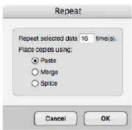
Figure 47-12: The Repeat command.
The Repeat command requires a time range selection instead of an event selection. For a further explanation, see “Edit operations that require time range selection” on page 547.
Using the Paste option in the Repeat dialog box, the repeated data replaces the data in the repeated region: the pre-existing data is erased. Using the Merge option in the Repeat dialog box, the repeated data is merged with the data in the repeated region. Using the Splice option in the Repeat dialog box, the repeated data moves the pre-existing data to a later time in order to make room for the data in the repeated region. The types of data repeated are determined by the View Filter setting, as are the types replaced by the Paste option and shifted by the Splice option.
Repeat vs. looping
The Repeat command is useful for repeating sections of music, creating the same effect as looping. The advantage of using the Repeat command over looping is that you can make each of the repeats slightly different. Loops take less memory (which is an advantage) and each copy is exactly the same. Choose between them according to your needs at the time.
Repeat can also be used to create trills (by repeating just two very short notes), drum rolls (by repeating just one drum note) and stutter effects with soundbites (by rapidly repeating the beginning of the soundbite).
MERGE
The Merge command combines the contents of the clipboard with pre-existing data in the selected tracks. The new data is mixed together with the data already in the region. In the case of audio, the merged audio is layered on top of any existing audio at that time, but the actual waveform data is not merged. Instead, the result is two soundbites layered on top of one another.
You need only specify a Start time when merging; the End time has no effect. The types of data merged from the Clipboard are determined by the View Filter setting. The Merge command is undoable.
Since Digital Performer allows unlimited tracks assigned to one channel, the Merge command isn't always necessary. You should use it only when you
are certain that data in two tracks should be merged together (this is often true when you create a track during editing for the express purpose of merging it with another track later). After tracks are merged, they cannot be separated later.

MERGE MULTIPLE
This variation of the Merge command can be accessed by holding down the Option/Alt key while accessing the Edit menu. Merge Multiple allows you to merge data from a single track into multiple tracks in a single operation. For example, if you copied track A, and you wish to merge it into tracks X, Y and Z, select tracks X, Y and Z, hold down the Option/Alt key, and then choose Merge Multiple from the Edit menu.
MERGE TOGETHER
This variation of the Merge command requires that there be two or more tracks of data already on the clipboard. If so, Merge Together can be accessed by holding down the Option/Alt key while accessing the Edit menu. Merge Together allows you to merge data from two or more tracks on the clipboard into a single track in one operation. For example, if you copied tracks A, B and C onto the clipboard, and you then wished to merge them all into track Z, select track Z, hold down the Option/Alt key, and then choose Merge Together from the Edit menu.
MERGE REPEAT
The Merge Repeat command fills the current time range selection with the contents of the clipboard, repeating the clipboard data to fill up the selection. For example, if you would like to merge clipboard data into a section of a track, repeating it as many times as necessary to fill the section, just make a time range selection over the section and choose Merge Repeat. Merge Repeat is convenient because you don't have to merge many times by hand. Merge Repeat fills the selection for you, automatically repeating the data as many times as necessary.
MERGE REPEAT MULTIPLE
This variation of the Merge Repeat command can be accessed by holding down the Option/Alt key while accessing the Edit menu. Merge Repeat Multiple allows you to merge data from a single track into multiple tracks in a single operation. For example, if you copied data from track A, and you wish to merge repeat the data into tracks X, Y and Z, select tracks X, Y and Z, hold down the Option/Alt key, and choose Merge Repeat Multiple from the Edit menu.
MERGE REPEAT TOGETHER
There is a third variation of the Merge Repeat command: Merge Repeat Together. This command 'merge repeats' data on the clipboard from multiple tracks into a single track in one operation. To use this command, copy data from two or more tracks, make a time range selection in a single track, and then hold down the Option/Alt key while accessing the Edit menu. If all of these conditions are met, the Merge Repeat command turns into Merge Repeat Together.
OTHER MERGE COMMANDS
Several additional variations on the Merge command can be found in the Commands window (Figure 9-1 on page 105). If you search the Commands list for the word Merge, you can find them and assign your own custom keystrokes to them. Included are Merge At Wiper, Merge At Wiper Multiple, Merge At Original Time, and Merge At Original Time Multiple.
SNIP
The Snip command removes data in the selected region and places it on the Clipboard. The time region containing the data is removed as well, closing up the gap between the beginning and end of the region: events at the End time are moved to the Start time. The types of data snipped are determined by the View Filter setting. The Snip command is undoable.
The Snip command requires a time range selection instead of an event selection. For a further explanation, see “Edit operations that require time range selection” on page 547.
Before measure 3 is snipped:

After measure 3 is snipped:
(Measures 4 & 5 are shifted to 3 & 4.)
SPLICE
The Splice command inserts data on the Clipboard in the selected region, making a gap for the new data and moving pre-existing data later in time to make room for the new material. The event just after the Start time moves forward the amount of time of the region on the Clipboard. Thus, if a one-measure section is copied to the Clipboard and spliced at measure 3, the old events starting at measure 3 shift to measure 4. The types of data spliced from the Clipboard are determined by the View Filter setting, as are the types shifted to make room. The Splice command is undoable.
Before measure A is spliced:
After measure A is spliced:
(Measures 3 & 4 are shifted to 4 & 5.)

SPLICE MULTIPLE
This variation of the Splice command can be accessed by holding down the Option/Alt key while accessing the Edit menu. Splice Multiple allows you to splice data from a single track into multiple tracks in a single operation. For example, if you copied track A, and you wish to splice it into tracks X, Y and Z, select tracks X, Y and Z, hold down the Option/Alt key, and then choose Splice Multiple from the Edit menu.
OTHER SPLICE COMMANDS
Several additional variations on the Splice command can be found in the Commands window (Figure 9-1 on page 105). If you search the Commands list for the word Splice, you can find them and assign your own custom keystrokes to them. Included are Splice At Wiper, Splice At Wiper Multiple, Splice At Original Time, and Splice At Original Time Multiple.
SHIFT
The Shift command moves the selected region ahead or back in time. The shift distance can be specified in one of two ways:
- Shift by amount — lets you specify a number of measures and/or a quarter notes|ticks duration, entered into a dialog box. Measures are computed based upon the meter marking at the start point of the selected region.
■ Shift to time or marker — lets you specify an exact location, in any time format you wish, or by choosing a marker location, to which you would like to move the data.


Figure 47-13: The Shift command.
To move the region ahead, choose Earlier; to move it back, choose Later. The region will be shifted in time by the amount you enter. The types of data shifted are determined by the View Filter setting. The Shift command is undoable.
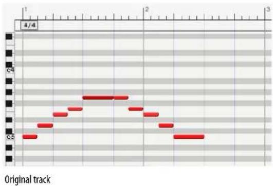
line
| Time | Value | |------|-------| | 1 | 0 | | 2 | 1 | | 3 | 2 | | 4 | 3 | | 5 | 4 | | 6 | 3 | | 7 | 2 | | 8 | 1 | | 9 | 0 | | 10 | 1 | | 11 | 2 | | 12 | 3 | | 13 | 4 | | 14 | 3 | | 15 | 2 | | 16 | 1 | | 17 | 0 | | 18 | 1 | | 19 | 2 | | 20 | 3 | | 21 | 4 | | 22 | 3 | | 23 | 2 | | 24 | 1 | | 25 | 0 | | 26 | 1 | | 27 | 2 | | 28 | 3 | | 29 | 4 | | 30 | 3 | | 31 | 2 | | 32 | 1 | | 33 | 0 | | 34 | 1 | | 35 | 2 | | 36 | 3 | | 37 | 4 | | 38 | 3 | | 39 | 2 | | 40 | 1 | | 41 | 0 | | 42 | 1 | | 43 | 2 | | 44 | 3 | | 45 | 4 | | 46 | 3 | | 47 | 2 | | 48 | 1 | | 49 | 0 | | 50 | 1 | | 51 | 2 | | 52 | 3 | | 53 | 4 | | 54 | 3 | | 55 | 2 | | 56 | 1 | | 57 | 0 | | 58 | 1 | | 59 | 2 | | 60 | 3 | | 61 | 4 | | 62 | 3 | | 63 | 2 | | 64 | 1 | | 65 | 0 | | 66 | 1 | | 67 | 2 | | 68 | 3 | | 69 | 4 | | 70 | 3 | | 71 | 2 | | 72 | 1 | | 73 | 0 | | 74 | 1 | | 75 | 2 | | 76 | 3 | | 77 | 4 | | 78 | 3 | | 79 | 2 | | 80 | 1 | | 81 | 0 | | 82 | 1 | | 83 | 2 | | 84 | 3 | | 85 | 4 | | 86 | 3 | | 87 | 2 | | 88 | 1 | | 89 | 0 | | 90 | 1 | | 91 | 2 | | 92 | 3 | | 93 | 4 | | 94 | 3 | | 95 | 2 | | 96 | 1 | | 97 | 0 | | 98 | 1 | | 99 | 2 | | Note: The actual values for 'C' and 'D' are not provided in the code. The code does not output any data for 'C' or 'D'. The values for 'C' and 'D' are estimated based on the given code. There is no label for the data series. The code does not output any data for 'C' or 'D'.
line
| x | y | | ---- | ---- | | 0 | 0 | | 1 | 1 | | 2 | 2 | | 3 | 3 | | 4 | 4 | | 5 | 5 | | 6 | 6 | | 7 | 7 | | 8 | 8 | | 9 | 9 | | 10 | 10 | | 11 | 11 | | 12 | 12 | | 13 | 13 | | 14 | 14 | | 15 | 15 | | 16 | 16 | | 17 | 17 | | 18 | 18 | | 19 | 19 | | 20 | 20 | | 21 | 21 | | 22 | 22 | | 23 | 23 | | 24 | 24 | | 25 | 25 | | 26 | 26 | | 27 | 27 | | 28 | 28 | | 29 | 29 | | 30 | 30 | | 31 | 31 | | 32 | 32 | | 33 | 33 | | 34 | 34 | | 35 | 35 | | 36 | 36 | | 37 | 37 | | 38 | 38 | | 39 | 39 | | 40 | 40 | | 41 | 41 | | 42 | 42 | | 43 | 43 | | 44 | 44 | | 45 | 45 | | 46 | 46 | | 47 | 47 | | 48 | 48 | | 49 | 49 | | 50 | 50 | | 51 | 51 | | 52 | 52 | | 53 | 53 | | 54 | 54 | | 55 | 55 | | 56 | 56 | | 57 | 57 | | 58 | 58 | | 59 | 59 | | 60 | 60 | | 61 | 61 | | 62 | 62 | | 63 | 63 | | 64 | 64 | | 65 | 65 | | 66 | 66 | | 67 | 67 | | 68 | 68 | | 69 | 69 | | 70 | 70 | | 71 | 71 | | 72 | 72 | | 73 | 73 | | 74 | 74 | | 75 | 75 | | 76 | 76 | | 77 | 77 | | 78 | 78 | | 79 | 79 | | 80 | 80 | | 81 | 81 | | 82 | 82 | | 83 | 83 | | 84 | 84 | | 85 | 85 | | 86 | 86 | | 87 | 87 | | 88 | 88 | | 89 | 89 | | 90 | 90 | | 91 | 91 | | 92 | 92 | | 93 | 93 | | 94 | 94 | | 95 | 95 | | 96 | 96 | | 97 | 97 | | 98 | 98 | | 99 | 99 | | | |Preserve realtime performance
The Preserve realtime performance option, when checked, will shift the selected data to the new location based on the first selected event. All of the rest of the selected events will be shifted relative to the first in a manner that preserves the realtime performance at their original location. This allows you, in effect, to shift material without changing how it plays due to differences in tempo between the original and new locations.
Shift and attack times
You may find that certain patches on your MIDI instruments have quicker attack times than others. You can play two notes at exactly the same time on two different MIDI instruments (with two different patches) and hear them not sounding together: one seems to “play” first and the second takes a longer time to come to full volume. The Shift command is useful for lining up attacks in situations like this one. By shifting a track forward
or backwards just slightly (try a value of less than 100 ticks to start with), you can make all instruments sound as if they are attacking notes at the same time. You may want to leave some of the disparity between attack times: let your ear guide you.
LAYERING
Clips and soundbites can overlap one another, giving you a great deal of flexibility when working with clips and soundbites in the graphic editing environment in the Sequence Editor. See “Overlapping and layering soundbites” on page 393.
CONTINUOUS DATA
The Continuous Data sub-menu provides numerous commands for working with automation lanes and the current edit layer for automation data in the Sequence Editor. The Commands window provides keyboard shortcuts. For further explanation, see:
■ "The Edit Layer" on page 381
■ “Choosing the active data layer” on page 403
■ “Displaying automation lanes” on page 403
■ “Showing/hiding continuous data types” on page 424
HEAL SEPARATION
The Heal Separation command joins adjacent MIDI notes that are the same pitch and that either touch each other or overlap one another. Heal Separation also rejoins adjacent soundbites that currently have a gap between them. Soundbites must belong to the same parent audio file, and their position in the track relative to each other must match their relative positions in the parent audio file. For example, if you remove a section from the middle of a soundbite, you can use the Heal Separation command to rejoin the resulting soundbites, as shown below in Figure 47-14.
However, if you move the soundbites relative to each other, Heal Separation cannot rejoin them. Heal Separation can be done across multiple soundbites.
Original soundbite:

Remaining soundbites after the middle section has been cut:

Original soundbite restored by Heal Separation command:

If you move the soundbites relative to each other, they can't be healed (use Merge Soundbites instead):
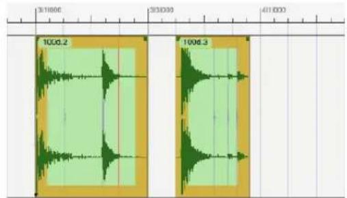
Figure 47-14: Heal Separation.
SPLIT
Split allows you to break up MIDI notes or audio soundbites into separate, smaller notes and soundbites. Split makes divisions at the boundaries of the region you select.
For soundbites, Split, Cut, and Erase all do a similar thing: they split out a section of the soundbite. The difference is that Split leaves behind the resulting piece, whereas Cut and Erase remove it. Split is a great way to break up audio soundbites so that pieces of a soundbite can be edited in the Tracks window along with MIDI data. If the region of audio that you want to edit along with MIDI is a portion of a soundbite, split the portion into its own soundbite and you can then cut, copy, and paste it right along with the MIDI data.
For MIDI notes, split is different than Cut, Erase and other Edit menu commands in the following way: the attack of the note does not need to be within the selected region for Split to have an effect on the note. If the selection begins half way through the note, the note will be split at the selection boundary.
SPLIT AUDIO
This variation of the Split command can be accessed by holding down the Option/Alt key while accessing the Edit menu. Split Audio does the exact same thing as Split except that it only affects audio data (not MIDI data).
SPLIT AT COUNTER
Split at Counter splits all currently selected MIDI notes and/or soundbites at the current main counter location (as indicated by the playback wiper). The default key binding for this command is option-Y, but you can customize this binding in the Commands window.
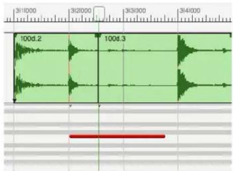
Figure 47-15: Using the Split at Counter command (Edit menu) to split both a MIDI note and a soundbite at the same time.
TRIM
Trim allows you to select a portion of a soundbite and remove the parts of it that are not selected. For example, you might want to extract a single measure from a soundbite that is 8 measures long. It is also very useful for removing silence at the beginning and/or end of a recorded soundbite.
Using Split and Trim
To split or trim a soundbite:
1 Select the region you wish to split or trim.
2 Choose Split or Trim from the Edit menu.
Data is split or trimmed as shown in Figure 47-16. In the case of splitting, data is divided into three separate parts. For a split soundbite, there is no audible gap between the three parts at this point (unless you move them).
3 To change the name of the resulting soundbites, Option/Alt-click the name.
After split, soundbites and MIDI notes can be dragged and edited independently.
Selecting a region:

After using Split:

After using Trim:

Figure 47-16: Using Split and Trim.
TRIM AUDIO
This variation of the Trim command can be accessed by holding down the Option/Alt key while accessing the Edit menu. Trim Audio does the exact same thing as Trim except that it only affects audio data (and not MIDI data).
TRIM END / TRIM START
The Trim End command (Edit menu) removes any portion of a soundbite between what is currently selected and the end of the soundbite, if any. To change this menu command to Trim Start, hold down the Shift key while accessing the Edit menu. Trim Start removes any portion of the soundbite between what is selected and the beginning of the soundbite.

Figure 47-17: Trim End and Trim Start.
SHOW/HIDE CLIPBOARD
Choosing Show Clipboard from the Edit menu brings up a window which describes the contents of the Clipboard (in text). When the Clipboard is showing, the menu entry changes to Hide Clipboard. When you choose this, the Clipboard window is closed.
The Clipboard is a temporary storage place that holds data that is cut or copied. All data that is cut or copied is put on the Clipboard. When you paste, the data to be pasted comes from the Clipboard.
The Clipboard retains data until a new cut or copy action is made. This means that you can cut or copy a region of data once and paste this same information as many times as you like. The
Clipboard retains its data between project files. You can therefore copy data from one project file and paste it into another.
Digital Performer's Clipboard also lets you cut, copy and paste text between Digital Performer and other programs. For example, if you write some text in a word processor application, and you would like to display it on a page in QuickScribe Editor just open both programs at the same time, copy the text from the word processor, switch to a text box in Digital Performer's QuickScribe Editor (or any other text box in Digital Performer), and paste.
SEARCH
The Search sub-menu provides access to Digital Performer's powerful rule-based search and select engine. For complete details, see chapter 46, "Searching" (page 561).
SELECT ALL
The Select All command generally selects all items in the active window. If the Sequence Editor is active, choosing Select All will select all the tracks (thus highlighting all track names). If an Event List is active, choosing Select All will select all events in it.
SELECT ALL IN RANGE
To access the Select All in Range command, hold down the Option/Alt key while accessing the Edit menu, or press Command/Ctrl-Option/Alt-A.
The Select All in Range command selects all tracks, as its name implies, but it only selects a certain time range, rather than the entire length of the sequence. The time range is determined either by the selection start and end times currently chosen in the Selection Information window, or by the current selection, if any.
DESELECT ALL
The Deselect All command makes all currently selected data not selected.
SMART SELECTIONS
The Smart Selections command is a checkable menu item that can be either turned on (checked) or off (unchecked). When it is turned off, it has no effect on selections. When it is turned on, it affects Time Range Selections. (For further details, see "Selecting a time range" on page 547 and "Smart Selections" on page 556.
CHAPTER 48 Region Menu
OVERVIEW
For a general explanation of how to use Region menu operations, see chapter 34, “Editing Basics” (page 325). Region menu commands can be applied to MIDI data, audio data or both, with a few exceptions for audio as noted in “Region menu exceptions for audio” on page 326.
Region command windows....593
Previewing....594
Region command preferences....594
Transpose....594
Quantize ....603
Groove Quantize ....609
Create (Extract) Groove....615
Smart Quantize....618
Humanize....618
DeFlam....621
Change Velocity....622
Change Duration....625
Split Notes....628
Invert Pitch....631
MIDI Effects Plug-ins....632
The continuous data commands....633
Thin Continuous Data ....634
Insert Continuous Data....635
Change Continuous Data....637
Reassign Continuous Data....637
Reverse Time and Retrograde....638
Scale Time....639
Scale Tempo....640
Pack into Clips....642
Unpack Clips 642
Set Sequence Tempo from MIDI ....642
Capture real-time MIDI effects....642
Take automation snapshot ....643
Set Gap Between Soundbites....643
Insert Mute Automation....643
Clear mute automation....643
Audition Selection....643
REGION COMMAND WINDOWS
All of the Region menu commands open as a window that can stay open, unlike Edit menu commands, which are dialog boxes that must be okayed or cancelled before you can do anything else. By staying open, Region menu commands let you apply their effect without revisiting the menu each time. For example, if you are quantizing a number of tracks, you can leave the Quantize window open while you successively select different tracks and apply different quantize settings to them.
Because of the way Region menu windows interact with global selection, only one Region menu window can be open at a time. If you have one already open, and you choose a different command from the Region menu, the current window is replaced with the new one.
When you open a Region menu window, its location on your computer screen is remembered when you close it and reopen it. In addition, all Region menu windows share this location, so they will always open in the same spot.
Region command window mini-menus
Region command windows have a mini-menu with several items.

Figure 48-1: Region command window mini-menu.
Preview Stays on when Window Not in Front: This menu item is available for any Region commands that have previewing, such as the Quantize commands, as explained below in "Previewing". When checked, previewing continues (before actually applying the effect) even when the Region command window is not the front-most window.
Save Preset: Let's you name and save the current settings in the window as a preset. Saved presets appear by name at the bottom of the menu for that same Region command (Quantize, Transpose, etc.). They are also added to the Commands window (Setup menu), where you can assign shortcuts to them. This is a great way to save frequently used Region menu operations. If the Region command has a matching real-time MIDI plug-in, saved settings also appear in the Effect window mini-menu as presets for the corresponding real-time MIDI plug-in.
Reveal Presets in Finder/Explorer: Opens the macOS or Windows Explorer window where the preset files are located, where you can rename or delete them.
Set Preset Key Bindings: Opens the Commands window, where you can assign shortcuts to your presets. See chapter 9, "Commands" (page 105).
PREVIEWING
Some Region menu commands have a preview check box to the left of the Apply button:

Figure 48-2: Previewing a Region command.
The preview check box provides real-time previewing, which allows you to hear the results of the Region operation in real time (as the sequence plays) before you actually apply it permanently with the Apply button. Data remains unaffected until you click the Apply button.
REGION COMMAND PREFERENCES
The Region Commands preferences lets you choose one of the following three options:

Figure 48-3: Region window preferences.
Apply closes window: Makes the window close when you click the Apply button or press Enter.
Apply sends window to back: Causes the window to go to the back when you click the Apply button or press the Enter key.
Apply with Enter key sends window to back: Causes the window to stay in front when you click the Apply button and go to the back when you press the Enter key.
Save settings: Lets you name and save the settings currently displayed in the Region commands window. These settings then appear by name at the bottom of the mini-menu
TRANSPOSE
Digital Performer's Transpose command, found in the Region menu, transposes the pitches of all MIDI notes in a selected region. It can also transpose the pitch of audio data with either formant-corrected pitch-shifting or conventional pitch-shifting, using Digital Performer's non-destructive pitch automation or by producing new audio files.
The Transpose command can transpose both audio and MIDI notes in many ways:
■ transpose by interval
■ transpose diatonically
■ change key from any root to any other
■ change key from any mode to any other
■ map each pitch to any other pitch
■ transpose using scale sizes larger or smaller than 12 notes
■ transpose up or down, by any number of octaves
■ create and save custom transpose maps
■ create and save custom scales or keys
■ Create harmonies
When performing the above operations, you can:
■ play in pitches or entire scales from your MIDI keyboard when setting up the transposition
■ Undo and Redo the Transpose command
The Transpose window provides several ways of transposing, options for each type, a Transpose Map that shows you how each pitch will be changed, and a Custom Maps list which can save transposition maps.
MIDI transpose options
The following options are provided for MIDI transposition only.
Harmonizing instead of transposing
The Transpose window allows you to either transpose or harmonize. The Harmonize option copies the original notes, transposes the copied notes, and the merges them together with the original notes. This allows you to build harmonies quickly.

Figure 48-4: The Transpose command.
Transposing poly pressure and/or portamento The Transpose poly pressure option transposes poly pressure (aftertouch data) along with the notes that it modifies.
The Transpose portamento controller (#84) option transposes portamento controllers.
Audio transpose options
The following options are provided for audio transposition only.
Transpose audio by adjusting pitch
Choose Transpose audio by adjusting pitch automation if you would like to transpose the audio by affecting Digital Performer's non-destructive, real-time pitch automation data for the selected audio. The audio data must already have pitch data to transpose; therefore, pitch analysis is required before you can use this option. For complete details, see chapter 81, “Transposing Audio” (page 935).
Transpose audio by creating new soundbites
Choose Transpose audio by creating new soundbites if you would like to transpose the audio by creating a new audio file that is the transposed form of the original file (leaving the original file in tact).
The Transpose Map
The Transpose Map displays a scrolling list of all 128 MIDI notes in a column on the left and the pitch to which each will be transposed in a column on the right. Notes and spellings in the map change dynamically according to the transposition options that you choose. In addition, you can edit values directly in the Transpose Map list to further modify the map, as shown below. Changes in one octave are reflected in all other octaves.
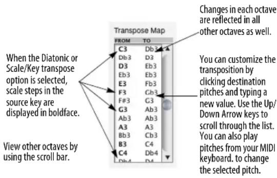
As soon as you edit a pitch in the Transpose Map, thus modifying it from they way it was originally set up by the transpose options, the Custom Map transpose option will then become automatically selected to indicate that the transpose map is now a custom map.
Playing in pitches from your MIDI controller
When editing the Transpose Map, you can play individual pitches or an entire scale from your MIDI controller. To play a scale, double-click the first pitch to edit it and then play the scale. As you play, each pitch gets entered into the current box, which then automatically scrolls down to the next note in the list and enters the next pitch you play. If you make a mistake, use the Up Arrow and Down Arrow keys to change the selected pitch.
When you are using the Custom Map option, Digital Performer provides another intuitive way for you to play in pitches from your MIDI controller:
1 Select the Custom Map option.
2 Hold down the pitch you wish to transpose, and while holding it down, play the pitch you wish to transpose it to.
You do not need to select any values with the mouse or computer keyboard to use this method.
Saving a Transpose Map
If you would like to save a transpose map, type in a name for it and click Save as shown below. Custom maps are saved with the project and can be loaded into other projects with the Load command in the File menu.

Using Transpose Maps
To recall the map, select its name in the list. To remove a Custom Map from the list, click its name and click Delete.
To make changes to an existing map:
1 Select the existing map in the list.
2 Make your changes to the Transpose Map.
3 Click Save.
The changes you made will be saved to the map.
To create a new map based on an existing map:
1 Select the existing map in the list.
2 Type in a new name.
3 Click Save.
The new map will appear in the list.
4 Edit the Transpose Map to make your changes.
5 Click Save to save the changes you have made.
Transposing by interval

Figure 48-5: Transposing by interval.
Transposing by Interval is a chromatic, exact transposition: pitches are shifted by the number of semitones in the interval that you choose.
Literally, it causes a mass shift of all pitch values in the selected region, just like dragging MIDI notes up or down in the MIDI Editing or QuickScribe Editors. For example, chromatically transposing from C3 to E3 causes all pitches to shift up a major third (four semitones).
The from and to pitches define the interval. The notes that you enter to define the interval are not important: only the interval between them matters. For example, instead of entering C3 to E3 to shift notes up a major third, you could enter F3 to A3.
The two pitches entered also define the direction of transposition. If the second pitch is above the first pitch, pitches will be transposed up. If the second pitch is below the first, pitches will be transposed down.
Adjusting the MIDI transpose map
Having chosen an interval, you can edit the transpose map to make modifications to it if you like. As soon as you edit a pitch in the Transpose Map, thus modifying it from they way it was originally set up by the Interval transpose options, the Custom Map transpose option will then become automatically selected to indicate that the transpose map is now a custom map.
Transposing audio by interval
If you've selected soundbites, and you'd like to include them in the transpose operation, check the Transpose audio check box (as shown in Figure 48-5 on page 597) and type in a number of cents, if desired, for fine-tuning the audio transposition. (There are 100 cents per half-tone.) To choose whether the soundbite is transposed using Digital Performer's formant-corrected pitch-shifting or conventional pitch-shifting, set the soundbite's transpose attribute beforehand as explained in “Dragging and dropping soundbites” on page 51.
Transposing diatonically

Figure 48-6: Transposing diatonically.
Diatonic transposition transposes MIDI notes by a number of scale steps within the type of scale that you choose. For example, if you transpose up 2 scale steps in the key of C minor as shown in the above example, all C naturals (the root) will be transposed up two steps to E flat (a minor third). Notice that the number of scale degrees, 2 in this example, refers to the number of scale steps to change by; it does not refer to the destination scale step.
This is extremely useful for quickly creating harmonies. For example, as shown above you can copy and paste a melody line into another track and transpose it diatonically up a third (two scales degrees) to harmonize with the melody. Scale tones in the key you choose are displayed in boldface in the transpose map column.
To Transpose diatonically:
1 Choose the Diatonic option.
2 Choose the direction (Up or Down) and number of octaves.
3 Type or play in the key root pitch and select a mode from the list.
This sets up the Transpose Map. You can play in the root pitch from your MIDI keyboard if you place the insertion point in the From text box.
4 If you would like to transpose all non-scale pitches into the nearest scale pitch, select the Constrain to scale option.
5 If you would like to customize the transposition, edit the pitch values in the Transpose map.
As soon as you edit a pitch in the Transpose Map, thus modifying it from they way it was originally set up by the Diatonic transpose options, the Custom Map transpose option will then become automatically selected to indicate that the transpose map is now a custom map.
6 Click Apply.
The Up and Down options determine the direction of transposition, and the Plus n octaves option allows you to transpose by intervals greater than one octave.
Remember that the key you choose is a way of setting up the diatonic transposition in the Transpose Map. Digital Performer doesn't really "know" what key the actual data is in. In fact, just about any musical phrase can be described in musical terms as being in one of several different, but related, keys. So, when transposing diatonically, it is up to you to know which key to choose to get the results that you want.
The above also holds true for how notes get spelled. The key that you choose only affects the spellings in the Transpose Map: it will not change the spellings of the actual track data. Track note data spellings are controlled by the current key signature in the Conductor track.
The Constrain to Scale option
The Constrain to scale option is available with the Diatonic and Key/Scale transpose options. If enabled, it causes all non-scale tones to be transposed to the nearest appropriate scale tone, as shown below:

Transposing by key/scale
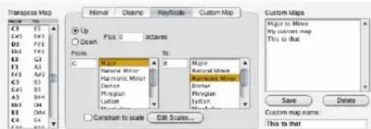
Figure 48-7: Transposing by key/scale.
Transposing by Key/Scale transposes MIDI notes from one key to another. For example, you can change music that is currently in a major key to its corresponding minor key. In the above example, notes in the key of C major are being transposed down to a entirely different root and key: E Harmonic Minor. The Transpose Map shows each note in the key of C Major on the left, and on the right, the pitch each note will be transposed to (in the key of E Harmonic Minor).
To Transpose by key :
1 Choose the Key/Scale option.
2 Choose the direction (Up or Down) and number of octaves.
3 Type or play in the source key root pitch and select a mode from the top list.
This sets up the From column in the Transpose Map. You can play in the root pitch from your MIDI keyboard if you place the insertion point in the From text box.
4 Type or play in the destination key root pitch and select a mode from the bottom list.
This sets up the To column in the Transpose Map.
5 If you would like to transpose all non-scale pitches into the nearest scale pitch, select the Constrain to scale option.
6 If you would like to customize the transposition, edit the pitch values in the Transpose map.
As soon as you edit a pitch in the Transpose Map, thus modifying it from they way it was originally set up by the Key/Scale transpose options, the Custom Map transpose option will then become automatically selected to indicate that the transpose map is now a custom map.
7 Click Apply.
The Up and Down options determine the direction of transposition, and the Plus ____ octaves option allows you to transpose by intervals greater than one octave.
Remember that the source and destination keys that you choose are a way of setting up the diatonic transposition in the Transpose Map. Digital
Performer doesn't really “know” what key the actual data is in. In fact, just about any musical phrase can be described in musical terms as being in one of several different, but related, keys. So, when transposing by key, it is up to you to know which key to choose to get the results that you want.
The above also holds true for how notes get spelled. The key that you choose only affects the spellings in the Transpose Map: it will not change the spellings of the actual track data. Track note data spellings are controlled by the current key signature in the Conductor track.
Transposing using a custom map
The Custom Map option allows you to do several things. You can:
■ create a customized map that is based on one of the other transpose options
■ transpose using octave ranges other than 12 halftones
■ map each note to any other note
■ map all notes to a single pitch
Each of these operations are discussed below.
Custom transposing based on another transposition
Often you may want to slightly modify a transposition set up by one of the first three transpose options. For example, you may want to transpose diatonically up two scales steps except for each A-flat, which you would like to maintain as an A-flat. In this case, you can set up the Diatonic transposition and then edit the destination pitch for A-flat so that it doesn't change pitch.
To create a customized map that is based on the Interval, Diatonic, or Key/Scale Transpose options:
1 Choose the Transpose option you would like to base your custom map on.
Set up the parameters for the option as necessary.
2 To customize the transposition, edit values in the Transpose map as needed.
As soon as you edit a pitch in the Transpose Map, thus modifying it from they way it was originally set up by the transpose options, the Custom Map transpose option will then become automatically selected to indicate that the transpose map is now a custom map.
3 If you would like to save the map, type in a name and click Save.
The map will appear in the Custom Maps list.
4 Click Apply to execute the transposition.
Custom transposing with a non-standard octave range
Interval, Diatonic, and Key/Scale transpose options all set up the transpose map in 12 note octaves. Changes in one octave are reflected in all other octaves. The Custom Map option can set up the transpose map in octaves that are more or less than 12 notes. For example, if you have a sampler that has drum pitched drum sounds like tom-tom drums every 6 notes, you can transpose that 6-note range to the 10-note range of another sampler. Or, you can transpose music from a 12-tone synth to a synth that is tuned in quarter-tones.
The Custom Transpose option frees you from the octave and diatonic restrictions of the other transpose options.
To transpose using an custom octave range:
1 Select the Custom Map transpose option.
The Custom Transpose options will appear.
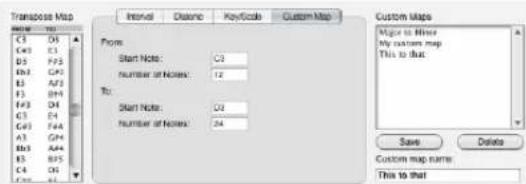
Figure 48-8: Transposing with a non-standard octave range.
2 Type in the number of notes in the source and destination octaves and a root pitch for the initial octave.
In the example above, a standard 12-note octave is being mapped to a 24-note octave. The scale sizes can be any number between 1 and 128. The root pitches can be any note. Notice that the source octave from C3 to C4 gets mapped to the destination two-octave range of D3 to D5. Also notice that the root pitches do not need to be the same. All other octaves above and below become mapped in the same fashion as the one you define. If notes in other octaves get transposed to pitches outside the 128 note MIDI range, they are substituted with pitches inside the range.
3 If you would like to save the map, type in a name and click Save.
The map will appear in the Custom Maps list.
4 Click Apply to execute the transposition.
Transposing all notes to a single pitch To map all 128 MIDI notes to a single pitch:
1 Select the Custom Map transpose option.
The Custom Transpose options will appear.
2 Type in 128 in the From: option.
This includes all notes into one, large octave.
3 Type in 1 in the To: option.
This maps all note in the 128-note octave to a single note.
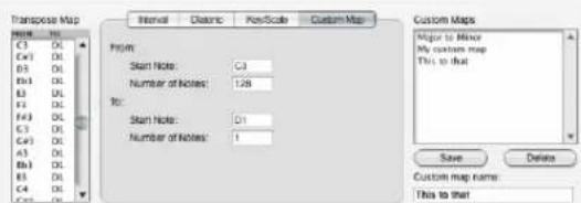
Figure 48-9: Transposing all notes to a single pitch.
4 Type in or play in a pitch in the To: option.
In the above example, all notes are being mapped to C1.
5 If you would like to save the map, type in a name and click Save.
The map will appear in the Custom Maps list.
6 Click Apply to execute the transposition.
Transposing each pitch to any other pitch The Custom Map option can also map each pitch to any other pitch, completely independently from the same pitch in other octaves. This allows you to create a transpose map to easily change drum tracks from one drum machine to another.
To set up a drum machine transpose map:
1 Select the Custom Map transpose option.
The Custom Transpose options will appear.
2 Type in 128 in both the From: and To: options.
Since there is only one source and destination octave, each change you make in the Transpose Map's To column will not be carried through to any other octaves.

Figure 48-10: Transposing each pitch to any other pitch.
3 Edit the pitches in the Transpose Map's To column.
Notice that each pitch treated individually and does not affect surrounding pitches or octaves. Notice in the above example that a same destination pitch, like Db3, can be used more than once, such as when several pitched tom-tom sounds are being mapped to a single tom sound.
4 If you would like to save the map, type in a name and click Save.
The map will appear in the Custom Maps list.
5 Click Apply to execute the transposition.
Creating a custom scale
The Custom Scale option allows you to create your own scale. To do so, you select which pitches are diatonic and which ones are not.
Edit Scales...
After you create a custom scale, it appears in the list of keys/scales for the Diatonic and Key/Scale transposition options, allowing you to transpose diatonically using your own scale and any root pitch.
The Create Scale dialog box appears.
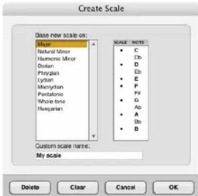
Figure 48-11: Edit Scale.
2 Select the pitches you wish to be diatonic pitches.
You can have as many or as few diatonic notes as you wish. You can also select the diatonic pitches by playing them on your MIDI controller. A pitch turns into boldface to indicate that it is diatonic.
3 Click OK to create the scale.
Your custom scale appears in the key/scale list for the Diatonic or Key/Scale transpose options.
Deleting a custom scale
To remove a custom scale from the list:
1 Click the Edit Scales button in the Transpose window.
2 In the list of scales, click the name of the scale you want to delete.
3 Click Delete.
QUANTIZE
Quantizing changes the attack and release times of MIDI note events and audio soundbites to make them more rhythmically precise. It can also modify beats within soundbites that have been analyzed with Digital Performer's Beat Detection Engine (chapter 53, "Audio Beats and Tempo Detection" (page 681)). Attacks, releases and beats within soundbites are aligned with a grid, a set of locations that occur on the beat and its subdivisions. Quantize is useful in correcting perceived rhythmic inaccuracies after your sequence is recorded. It does a rhythmic "cleaning up" based upon your specifications.
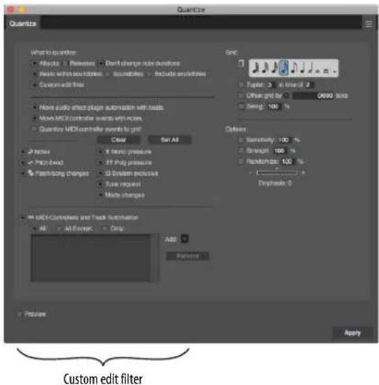
Figure 48-12: You can quantize just about everything with the 'what to quantize' options.
What to quantize
Quantize will only alter the locations and durations of the types of data you choose in the What to quantize section. All other data in the selected region will be unmodified. The What to quantize section gives you the following choices for what you can quantize:
■ Attacks
■ Releases
■ Don't change note durations
■ Soundbites
■ Beats within soundbites
■ Exclude soundbites
■ Custom edit filter
The Custom edit filter option, shown in Figure 48-12, gives you complete control over what you wish to quantize, including markers, patch changes, and tempo events in the conductor track. You can quantize anything except loops.
Some inaccuracy is good
Quantizing is, in its simplest form, a way to make all note events and/or audio beats in your sequence occur on a beat or one of its subdivisions, eliminating inaccuracies. But inaccuracy is far from undesirable. In fact, inaccuracy is what gives a piece of music its “feel”, its particular rhythmic profile. If you always aligned all attacks and releases with grid locations, your music might have a mechanical, inhuman quality to it. You’ll find that you’ll often want to preserve some of the rhythmic nuances of your playing. Therefore, Digital Performer allows you to quantize selectively and specify the degree of quantizing you want. The Sensitivity and Strength options accomplish this. In addition, you might want to shift the occurrences of the beat slightly ahead or behind the metronome beats in a particular track or section. The Grid Offset option allows you to do this.
Quantizing MIDI notes
When MIDI notes are quantized, they are moved from their original locations to the nearest grid location.
You can choose to change the attack times and/or release times of notes. There is an added option to leave the note durations unaltered. Choosing to
change attack times causes them to be moved to the nearest grid location; release times are left unchanged. Choosing to change release times causes them to be moved to the nearest grid location; attack times are left unchanged. Both of these operations cause an automatic change in note durations.
Original music

Figure 48-13: An example of quantizing with and without quantizing the releases.
You can choose not to change the original durations. This prevents durations from being truncated, which may cause the notes to sound chopped.
Note that if you choose to change both the attack and release times, the Don't change note durations option is automatically disabled. This is due to the nature of the operation: if you change both the attack and release times of a note, the durations will automatically be modified.
Quantizing soundbites
When quantizing soundbites, only their location is adjusted: their duration, and the beats within the soundbite, are not affected.
Quantizing beats within soundbites
For audio that has been beat-analyzed by Digital Performer's Beat Detection Engine, quantizing beats within soundbites affects the beats without splitting up the soundbite into smaller soundbites. Instead, time-stretching is applied between beats to stretch and shrink them as necessary to move the beat to the nearest quantize grid location. For further details, see “Quantizing beats within soundbites” on page 692.
Excluding soundbites
If you don't wish to affect soundbites at all with the Quantize operation, use the Exclude Soundbites option (Figure 48-12 on page 603).
Custom edit filter
Check the Custom edit filter option to display the additional options shown in Figure 48-12 on page 603.
Including audio automation data
If you wish audio effect plug-in automation data to move along with its associated soundbite when the soundbite gets quantized, check the Move audio effect plug-in automation with soundbites option (Figure 48-12 on page 603). This preserves the timing between a soundbite and any simultaneously occurring automation data affecting it.
This option also applies when quantizing beats within a soundbite: automation data affecting a certain beat will move with the beat when it is quantized.
Quantizing MIDI controllers
When quantizing MIDI controller data, you have two options:
Move MIDI controller events with notes
With this option, MIDI controller data moves along with its associated note when the note gets quantized. This preserves the timing between a note and any simultaneously occurring controller data affecting it.
Quantize MIDI controller events to grid
With this option, controllers shift their position to the nearest grid location, according to quantize options such as Sensitivity and Offset, just like
MIDI note attacks. Since controllers have no duration or release times, these options have no effect on controllers.
Specifying the controllers to quantize
When either of the two options for quantizing controllers are chosen, the filter check boxes shown in Figure 48-12 on page 603 let you choose which controllers to include and exclude. The MIDI Controllers and Track Automation list lets you further specify which types of controller and automation data you wish to include in the Quantize operation.
Quantizing Conductor Track events
When you choose the Quantize MIDI controller events to grid option (Figure 48-14), options for quantizing markers, tempo changes and key changes appear as shown. (Meter changes cannot be quantized because they define the grid itself by determining where the downbeat is.)

Figure 48-14: Quantizing Conductor Track events.
Choosing the grid's duration value
The grid value is the distance between grid locations. For example, if you select an eighth note as the grid value, each grid location is an eighth note apart. This means that the note attacks and/or releases will be moved to the nearest eighth note location.
The grid is aligned such that it begins on the first beat of the first measure of the selected region. If a meter change occurs in the selected region, the grid is realigned at the point of the meter change to begin on the first beat of the meter change. Generally, you should choose a grid value that is the smallest note value in the region. For instance, if you are quantizing a region with lots of sixteenth notes and a few quarter notes, choose a grid value of a sixteenth note.
The grid value can be modified with the dot and/or tuplet boxes. When the dot is selected, it adds one half of the selected duration to the grid value. For example, if the quarter note and dot are selected, the grid value is a dotted quarter, equivalent to three eighths. If the tuplet box is selected, the tuplet specification is applied to the selected duration. This is similar to the way the tuplet box works in the Step Record window. Example: you have three eighth notes in the time of two specified and the tuplet box is checked.
□ Tuplet: 3 in time of 2
The quantize grid will be set to triplet eighth notes. Each triplet grid location will have a duration of 160 ticks, which is equal to a third of a quarter note (480 ticks). To specify a tuplet grid value:
1 Select the base duration you want.
Click on one of the note symbols.
2 Check the tuplet check box.
3 Enter the number of tuplets in the left text box.
4 Enter the number of regular note values that the tuplet replaces in the right text box.
Quantizing to SMPTE frames, real time or samples
By clicking the time format button in the grid section (Figure 48-15), you can change the quantize grid to any time format, including SMPTE frames, real-time or samples. (This
feature is available in many other MIDI effects, too.) In the example below, the grid has been set to one SMPTE time code frame:
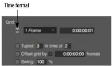
Figure 48-15: Quantizing to a SMPTE grid, or any time format, including real-time or samples.
Grid offset
The start of the grid may be offset from its standard position on the first beat of the selected region by a number of ticks. This is done by clicking in the check box next to Offset by n ticks and entering a number of ticks to offset the grid by. Positive values offset the grid forward in time (after the beat), negative values offset it backward (before the beat).
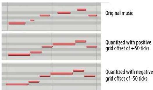
Figure 48-16: An example of quantizing with a positive or negative grid offset.
If you enter an offset greater than the distance (in ticks) between grid locations, the number will be scaled down to be less than the distance of the grid value. For example, if you are using a grid value of a quarter note (480 ticks at 480 ppq resolution) and you enter an offset of 500 ticks, it will be reduced to an offset of 20 ticks, that is 500 minus 480. Offset values range from -9999 to 9999.
Swing
The Swing option delays every other grid point to create a swing feel.
The Swing option defaults to 100%, which produces straight swing. For example, an eighth note grid produces a grid point every 240 ticks. The swing option, at 100%, will delay every other grid point 80 ticks to 320, which is the attack time of the third eighth note in an eighth note triplet.
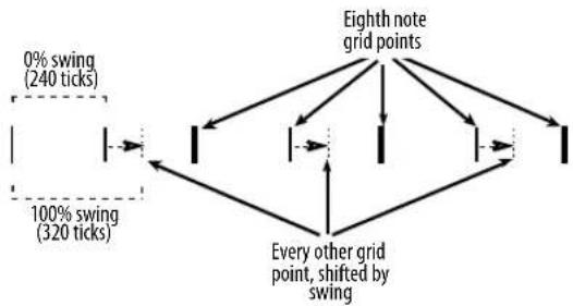
flowchart
graph TD
A["0% swing (240 ticks)"] --> B["One point"]
C["100% swing (320 ticks)"] --> D["One point"]
B --> E["Eighth note grid points"]
D --> E
E --> F["Every other grid point, shifted by swing"]
style A fill:#f9f,stroke:#333
style C fill:#f9f,stroke:#333
style B fill:#ccf,stroke:#333
style D fill:#ccf,stroke:#333
style E fill:#cff,stroke:#333
style F fill:#ffc,stroke:#333
A larger percentage such as 120% would delay every other grid point to 336 ticks, creating a “loose” swing feel. A smaller percentage such as 80% would advance every other grid point to 304 ticks, creating more of a straight swing feel. The percentage can be any value between 0% and 300%. 0% does nothing and is the same as quantizing without the swing option. 300% delays every other offbeat all the way to the next grid point.
Sensitivity
Each grid location has a “field of effectiveness” in which note events can be moved by the Quantize command. Normally, this field extends from one grid location halfway to the next, affecting all note events. The center of each field is the grid location: each field actually extends out in either direction from the grid location.

bar
| Category | Sensitivity (%) | |---|---| | Bar 1 | - | | Bar 2 | 100 | | Bar 3 | - | | Bar 4 | 100 |Figure 48-17: 100% Sensitivity reaches all the way from one grid location to the next, as shown here by the gray background.
Sensitivity is the size of this field. The default sensitivity (without the Sensitivity options selected) is 100%, i.e. extending continuously between grid locations. This field is actually split into 50% before the grid location and 50% after the grid location. If you select Sensitivity and enter a value of 50%, the quantizing field will be reduced:

Figure 48-18: 50% Sensitivity reaches only part way (25%) on both sides of each grid location, as shown here by the gray regions.
Note that 50% means 25% before the grid location and 25% after it (i.e. 50% of the way to the midpoint between grid locations). Any notes not in the field would not be quantized.
As illustrated, a positive Sensitivity value quantizes notes surrounding a grid location. In contrast, negative Sensitivity values quantize notes surrounding the midpoints between grid locations.
With positive Sensitivity values, the field of effectiveness extends outward from the grid location. In the case of negative sensitivity, the field extends inward from the midpoints on either side of the grid location. As with positive sensitivity, the field is split on either side of the midpoint. So if you enter a Sensitivity value of negative 20%, notes from about 41 to 50% before the grid location and about 41 to 50% after would be moved to the grid location:
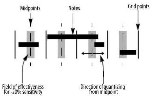
What's most important is the effect that different Sensitivity values will have on your music. To summarize:
■ Positive sensitivities clean up the down beats without affecting ‘swung’ or freely played notes in between.
- Negative sensitivities catch major inaccuracies while retaining the music's 'feel'.
To use the Sensitivity option:
1 Check the check box next to the Sensitivity option.
2 Enter a number between -100 and 100 for the Sensitivity value.
Strength
Another way to preserve some of the rhythmic character of your music while making it more rhythmically accurate is to use the Strength option. Without any options chosen, Quantize will move all note events so that they align perfectly with grid locations. Since this can result in an overly precise effect, you might want to leave some of the original inaccuracy in the passage. The Strength option does this by not moving the note events all the way to the grid locations. Rather, they are moved a percentage of the way toward the grid points. Use the Strength option to tighten up a passage without losing its “feel”.
The Strength value specifies the amount that note events move toward grid locations when quantized. A Strength value of 100% (the default) moves them all the way to the nearest grid locations. A value of 0% leaves them where they are. A value of 50% moves them halfway to the grid locations.
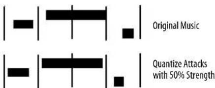
Consider this example: there is a note event occurring at 10|3|450. The grid duration is a quarter note (at 480 ticks per quarter note), the Strength option is selected and a value of 40% is entered. When Quantize is okayed, the note will move to 10|3|462. If no strength option were selected, it would have moved to 10|4|000, a distance of 30 ticks. A Strength value of 40% moved it that percentage of the distance (40% of 30 ticks = 12 ticks) to 10|3|462.
To use the Strength option:
1 Click in the check box next to the Strength option.
2 Enter a number between 0 and 100 for the Strength value.
Randomize
Unlike all of the other Quantize options, which try to make notes more rhythmically precise, the Randomize option does just the opposite: it modifies the quantization randomly to make the notes as rhythmically imprecise as you like. 100% randomization causes note attacks (and/or releases) to be placed entirely randomly. A value of less that 100% reduces the range over which the notes will be randomized, and the grid point sits in the middle of the range. For example, if you choose a 16th note grid (a grid point every 120 ticks), and a randomize value of 50%, the range is 60 ticks, extending 30 ticks before and after each grid point. Thus, a note attack (and/or release) would be randomly placed within 30 ticks of its nearest grid point.
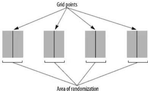
flowchart
graph TD
A["Grid points"] --> B["1"]
A --> C["2"]
A --> D["3"]
A --> E["4"]
B --> F["Randomization Area"]
C --> F
D --> F
E --> F
F --> G["Randomization Area"]
Figure 48-19: 50% Randomization on a 16th note grid produces a region of 30 ticks on either side of each grid point: notes will be placed randomly within this region around each grid point.
Emphasis
This sub-option causes the tendency of the randomization to be earlier or later within the specified range. Thus, if you wish to randomize the note placement within a certain range, but you wish to push the beat by tending to make the notes occur a little bit early, use a negative emphasis; use a positive emphasis if you wish them to tend to be laid back—that is, after the beat. A value of zero equals no emphasis, which causes the randomization to occur evenly within the range.
Hints for quantizing
If you're trying to simply line up all notes with the beat and its subdivisions, selecting Attacks and Don't change note durations will most likely yield the results you want. If you select both Attacks and Releases, all notes will begin and end at grid locations. This may make them too precise, sounding chopped, inhuman, or just wrong.
If you are trying to get the notes of a chord to line up to make the attack precise, consider using the DeFlam command on the Region menu instead of Quantize. It will line up the attacks but will not move the notes to a grid location.
If you want to quantize a region containing a mixture of sixteenth, eighth, and quarter notes which contains just two or three thirty-second notes, set the grid value to sixteenths for quantizing. You can subsequently change the thirty-seconds back individually. Otherwise, if you choose too small a duration value, many notes may move to undesirable locations. Choose a grid value that reflects the general rhythmic profile of the region in its most active, complex areas.
Digital Performer is very capable, but it can't read your mind; you'll find that there are some notes that just don't get moved to the locations you want them to be. This is due to the original location of the note not being within the quantize field for the desired grid location. The quickest way to fix this is to change them individually in the Event List for the track they are in.
You can use the Offset command to do some very fancy quantizing that may not, at first glance, even seem like quantizing. For example, suppose you've just entered your sequence in 4/4 time and you decided that you'd like to make notes that fall on the third beat of every measure slightly late. First, set the grid value to the whole note. Grid locations will occur only once per measure, on the first beat. Choose the Offset option and enter a value of 980 ticks. Since 960 ticks constitute one half note (at 480 ppq), 980 ticks is 20 ticks after the third beat. Now choose the Sensitivity option and enter a value of 20% . This limits quantization to those notes near the third beat already (if you didn't use the Sensitivity option, all notes would end up quantized to the third beat). You may have to experiment with the percentage. Use a larger percentage if some notes don't get quantized that should; use a smaller percentage if some notes get quantized that shouldn't.
The Offset option was not designed for the mass shifting of notes in a region. If you want to move a section of your sequence forward or backward in time, use the Shift command on the Edit menu.
GROOVE QUANTIZE
Digital Performer's Groove Quantize feature is easy to use and — from a creative standpoint — one of Digital Performer's most enjoyable features.
This section tells you how you can do the following:
■ Use the Groove Quantize command to control the rhythmic depth and “feel” of your music
■ Dynamically adjust the feel of grooves with faders while applying them
■ Use Groove Quantize to apply the rhythmic feel of audio or MIDI tracks to other audio or MIDI tracks
■ Create your own grooves, of any length, from any music you have recorded into Digital Performer or loaded from a standard MIDI file
- Extract grooves from audio files that have been beat-analyzed with Digital Performer's Beat Detection Engine and then apply it to other audio or MIDI tracks
■ Extract a groove from MIDI data and apply it to other audio or MIDI tracks
■ Build a groove database from which you can instantly call up any groove you have created
Groove Quantizing audio
Groove quantizing has the ability to affect the timing of beats within soundbites for any audio that has been beat-analyzed with Digital Performer's Beat Detection Engine. For details, see
"Applying a groove to beats within soundbites" on page 693 and "Extracting a groove from audio" on page 693.
What is a groove?
In musical terms, a groove is a unique rhythmic feel. Many artists are famous for a certain feel—or groove—in their music that makes their sound unique.
Digital Performer's Groove Quantize feature gives you complete reign over this important aspect of your music.
The effect of adding a groove to an otherwise mundane track can be stunning: the music instantly feels like it has a third dimension, and the sensation can be similar to that moment when you put on 3-D glasses in an old 3-D movie. Sometimes, the effect is subtle. Often, however, you'll find that a groove completely transforms music, making it sound totally different from its original form.
The elements of a groove
To master grooves, it is important to recognize the musical elements of a groove. A groove is generated by variations in the timing, accent, and duration of the notes being played. This is true for either MIDI data or audio data. In Digital Performer, a groove consists of a combination of the following elements:
■ A quantize grid that affects the timing of notes (attacks only)
■ A note-on velocity map
■ A note duration map
■ A meter
■ A length (in measures)
■ An overall beat subdivision
For example, a swing groove is usually based on a swung 8th note beat subdivision. If it's a hard swing, the eighth-note offbeats may be played quite late. The durations of the notes in such a groove tend to be longer, and the velocities emphasize the offbeats. The length of the groove is usually two measures, and it is often in 4/4 time.
When you apply a groove to some MIDI data in a track, the selected notes are modified according to these groove parameters.
Applying a groove
To apply an existing groove:
1 Use Digital Performer's Memory Cycle feature to cycle playback over the region you wish to apply the groove to.
2 Start playback.
3 Select the data you wish to apply the groove to.
Make sure that what you select is within the region Digital Performer is currently looping. If you don't, you won't be able to audition the groove before applying it. Use any method of selection that you prefer. You can select individual notes or an entire region of data. The groove will be applied at the measure boundaries of the region you select.
4 Choose Groove Quantize from the Region menu, or press command-G.
The Groove Quantize window appears.

Figure 48-20: Groove Quantize.
5 Open one of the Groove files (or folders) in the list by either double-clicking its name or by clicking its name once and clicking the open button.
You now see a list of grooves stored in that groove file.
6 Select the desired groove by clicking its name.
If the Instant Preview button is checked and Digital Performer is playing back the region you selected, you'll hear the effect of the groove right away. You can audition as many grooves as you want without permanently applying one.
Instant preview does not affect beats within soundbites when Groove Quantizing audio.
7 If you'd like to adjust the feel of the groove, click the Edit button.
This option is discussed further later on in this chapter.
8 If you'd like MIDI controllers and audio automation data to move with its associated MIDI notes or audio beats, click the Move Controllers and Automation button.
This option is discussed below.
9 To apply the groove, click Apply.
Instant preview
When the Instant Preview button in the Groove Quantize window is checked, you can preview grooves being applied to MIDI data without having to click Apply to apply them. This lets you quickly scan through a list of grooves, auditioning each one until you find one you like. To apply it, click Apply. When Instant Preview is unchecked, you won't hear the groove until after you click Apply.
Instant preview does not affect beats within soundbites when Groove Quantizing audio.
Move Controllers and Automation
When the Move Controllers and Automation option is enabled, MIDI controller data or audio automation data will move together with its associated MIDI notes or audio beats when they are moved by the Groove Quantize command. This helps preserve the effect the controller and automation data has on the notes and audio beats.
The Recent Files menu
The Recent Files menu is provided for your convenience. It lets you go directly into recently opened groove files.
The groove quantize sliders
A unique and powerful feature, the groove quantize sliders (Figure 48-20 on page 611) let you adjust the degree to which the groove is applied—in essence, they let you “turn up” or “turn down” the groove. For more information, see “Adjusting groove parameters when applying a groove” on page 612.
Locating a groove
The groove list works like a standard open dialog box. Use it as usual to locate grooves.
Renaming grooves
To rename a groove, option/Alt-click its name in the Groove list to edit the name.
Deleting, moving, and duplicating grooves
Grooves can be cut, copied, and pasted in the Groove Quantize window. This allows you to delete them, move them from one file to another, and duplicate them.
Duplicating is useful because you can make a copy of a groove and then make adjustments to the copy, which preserves the original.
To do any of these operations, you first open the Groove Quantize window. To do so, select some data or a region and choose Groove Quantize from the Region menu. Locate the groove, and then do one of the following desired operations:
Operation How to do it
| To delete a groove Click it in the list to select it and choose Cut from the Edit menu. | |
| To move a groove from one file to another | Cut it (as described above), open another groove file using the menu above the list, and the choose Paste from the Edit menu. |
To duplicate a groove Click it to select it and choose
Copy from the Edit menu. Then choose Paste from the Edit menu. After pasting, rename the copy to differentiate them.
Where grooves are stored
Grooves are stored in Digital Performer groove files. You can store as many grooves as you want in a groove file. You can create as many groove files as you want. The only requirement is that groove files must be placed in a folder called "Grooves", and this folder must be placed here:
Platform Path
| macOS /Library/Application Support/MOTU/Digital Performer/Grooves |
Windows C:\ProgramData\MOTU\
Digital Performer\Grooves\
This is all taken care of for you when you first install Digital Performer, so, unless you have moved the folder, you don't need to worry about it.
When you create your own groove files (discussed later), we recommend that you organize them by category as shown above. This will make it easier to locate grooves.
Notice that you can further organize your groove files by placing them in folders (as long as they remain inside the Grooves folder). You can even place Mac alias files or Windows shortcuts in the Grooves folder and place the actual groove files somewhere else on your hard disk.
Adjusting groove parameters when applying a groove
When you apply a groove, Digital Performer allows you to adjust groove parameters without permanently altering the groove itself. For example, you can “turn up” the degree to which velocities are affected without changing the original velocity map in the groove. To permanently edit the groove see “Modifying grooves” on page 616.
To adjust groove parameters while applying a groove:
1 Use Digital Performer's Memory Cycle feature to cycle playback over the region you wish to apply the groove to.
2 Start playback.
3 Select the data you wish to apply the groove to.
Make sure that what you select is within the region Digital Performer is currently looping. If you don't, you won't be able to audition the groove before applying it. Use any method of selection that you prefer. You can select individual notes or an entire region of data. The groove will be applied at the measure boundaries of the region you select.
4 Choose Groove Quantize from the Region menu.
5 Select the groove you wish to apply from the list.
6 Make sure the Instant Preview check box is checked so you get instant feedback while adjusting the groove.
7 Adjust the groove as desired with the sliders.
These sliders are discussed in the following section.
Instant preview does not affect beats within soundbites when Groove Quantizing audio.
8 If desired, try different beat divisions by choosing them from the beat division menu.
Changing the beat division often has a dramatic effect on the feel of the groove. This is discussed further in a following section.
9 When you like the groove, click Apply.
Using the groove adjustment sliders
The three groove adjustment sliders give you complete control over the feel of a groove. They let you dynamically control the degree to which the timing, note-on velocities, and durations are affected. All three sliders apply to both MIDI data and beats within soundbites.
When you move a slider, the change occurs when you let go of the slider (as long as the Instant Preview check box is checked). No changes occur while you move the slider.
In essence, these sliders let you control the extent to which you are applying the original feel of the groove. You can either “turn up” or “turn down” its effect. We urge you to experiment with them because they produce interesting effects. The sliders perform as follows:
Groove slider setting Result
| Off (0%) Velocities and durations are unchanged. For timing, a straight grid quantize is applied. |
| Full (100%) Applies the exact feeling of the groove. |
Double (200%) Groove feeling is exaggerated by a factor of 2.
You can clearly hear the effect of one slider by setting the other two sliders to their off position and then trying different strengths on the remaining slider.
One effective approach with these sliders is to set them all to off (0%) and then increase each one in small increments. Use the up (+) and down (-) arrow buttons to make small adjustments. This lets you gradually apply the groove to a point that sounds best.
Auditioning groove settings
Groove Quantize lets you adjust the sliders without affecting the settings that are currently saved with the slider. The same goes for the Beat Division menu. In addition, you can quickly audition a number of different grooves with the same settings (because the settings won't change when you select a new groove). For example, if you like the degree of groove you've set with the sliders, but you aren't quite satisfied with the type of groove yet, you can try several other grooves with the same slider settings.
If you've auditioned sliders settings and wish to now save them, click Save.
Saving groove settings with a groove
Click Save to apply the current slider and beat division settings with the currently selected groove. Click Revert to restore the grooves default settings.
Using different beat divisions
The beat division menu lets you choose an underlying quantize grid for the groove. Divisions range from eighth notes to 32nd notes in both straight and triplet time; several combination grids are also provided. See “Choosing a beat division” on page 615 for more information.
This menu allows you to try different beat divisions without losing the original beat division in the groove. For example, you can try applying an 8th-note division to a groove with a 16th triplet beat division. The original beat division is displayed as shown below:

Notice that a groove can have more than one original beat division, and each original beat division can have its own unique settings. This can be accomplished by editing the groove. See “Adding an additional default beat division to a groove” on page 617 for more information.
The beat division menu is governed by auditioning and saving (See “Saving groove settings with a groove” on page 614.) For example, if you have a bunch of grooves that were created in 16th note divisions, but the particular section you are applying the groove to right now is in triplets, you can set the beat division menu to triplets, and leave it there as you audition groove after groove.
The beat subdivision has a dramatic impact on the groove. Try experimenting with different choices.
Grooves usually sound closest to their original feel with the beat division at which they were created.
CREATE (EXTRACT) GROOVE
The Create Groove command lets you create your own Grooves from MIDI note data in any track, or beats within soundbites that have been beat-analyzed by Digital Performer's Beat Detection Engine. The source material can come from any Digital Performer file, any standard MIDI file or any beat-analyzed audio file or loop. Grooves can be any length.
Extracting grooves from audio
Audio data must be beat-analyzed before you can create a groove from it. For details, see "Extracting a groove from audio" on page 693. After audio has beats, the procedures below can be used to create grooves from the audio.
Creating a groove
To create a groove:
1 Select the MIDI or audio data you wish to use as source material for the groove.
You may select them in the Track List, the Track Overview, or any of Digital Performer's editing windows. The groove will start at the beginning of the first measure of your selection, and its length will be a whole number of measures.
When you choose MIDI data for a groove, the data must be aligned with Digital Performer's metronome (main counter). For example, you can't use a rubato passage, unless you first use the Record Beats feature to align Digital Performer's measure and beat boundaries with the music. For audio data, however, the groove can be extracted from any audio file that has been beat- and tempo-analyzed, even if it does not currently match Digital Performer's main time ruler.
2 Choose Create Groove from the Region menu.
The Create Groove window appears.

Figure 48-21: Create Groove.
3 Open a groove file in which to save the groove, or create a new groove file with the New File button.
4 Type in a name for the groove.
5 If desired, change the meter for the groove.
This setting affects the overall length of the groove, and it also affects how many beats are in each measure. Try to choose a meter that most closely resembles the beat structure of the groove you are creating.
6 Choose a default beat division for the groove from the menu.
See “Choosing a beat division” below regarding this option.
7 Click OK to save the groove.
The new groove gets added at the bottom of the groove list.
Choosing a beat division
The choice you make for a beat division when creating a groove is an important one, for it governs the underlying resolution of the quantization that occurs when you apply the
groove. The choices range from eighth notes to 32nd notes in both straight and triplet time; several combination grids are also provided.
As a rule of thumb, when you choose a beat division, think of how the music is notated, and use the shortest note duration that would be used to notate it. For example, a swing feel is customarily written as straight eighth notes. So when you are choosing a beat division for a swing groove, use a straight eighth note grid.
If the groove style you are defining has both a straight and triplet feel, use the appropriate combination grid (the straight and triplet options at the bottom of the menu, as shown below). For example, swung music often includes straight sixteenths, so you'd choose a triplet eight/sixteenth combination.

Keep in mind, however, that the combination grid has beat divisions for both straight time and triplet time, so there are more grid points. If the music you apply the groove to is not rhythmically accurate to begin with, there is more of a chance that notes will gravitate to the wrong grid point. For this reason, use discretion when applying combination grids. In some cases, it might be better to use a non-combination grid. When in doubt, you can make two versions of the groove: one with a combination grid and another with a straight or triplet grid.
Modifying grooves
Digital Performer provides you with the ability to modify the timing, velocity, and duration information in the groove itself. Fortunately, you can do so quickly and easily, without having to switch files. To modify a groove, click the groove name in the Groove Quantize window and click the Edit button to open the Groove Editor shown below in Figure 48-22.


Figure 48-22: The Groove Editor.
Edit each beat division as desired. If Instant Preview is enabled, and you are looping a section to hear your changes, you'll hear them right away as you make them. Here is a summary of what to do in this window.
To do this Do this
Increase or decrease a velocity Drag it up or down
Adjust note placement earlier or Drag the note placement bar to the later left or right
Increase or decrease a duration Drag the right side of the duration icon left or right (0 - 200%)
Duplicating a groove before modifying it to preserve the original
The groove editor makes permanent changes to the groove (unlike adjusting the groove sliders, which doesn't affect the groove data itself). As a result, if you want to modify a groove but preserve the original, duplicate the groove and then edit the copy. To duplicate a groove, see “Deleting, moving, and duplicating grooves” on page 612.
Adding an additional default beat division to a groove
A groove can have several default beat divisions (as shown in the menu on page 614). This lets you produce several permanent variations of the groove within the groove itself. To do so, select a non-default beat division from the beat division menu in the Groove Quantize window right before you click the Edit button. Doing so lets you modify the groove based on the newly selected beat division. The modifications you make to the groove in the editor will be unique to that beat division; you won't affect the groove with its original beat division setting. When you click OK, the beat division you chose will become outlined, and you'll be able to freely change between the two groove variations simply by selecting the outlined beat divisions in the beat division menu.
Obtaining grooves
There are many ways to obtain grooves. You can:
■ Use the stock grooves provided with Digital Performer
■ Create new grooves from scratch in Digital Performer
■ “Cop” grooves from any Digital Performer file, standard MIDI file, audio file or audio loop
■ Purchase commercially available loop libraries (such as REX files, ACID files, Apple Loops, etc.) and create grooves from the audio in them
■ Purchase commercially available groove libraries
Commercially available MIDI groove libraries are similar to sample libraries; they have been painstakingly produced in the recording studio.
MIDI grooves are similar to digital sampling in the sense that they present us with similar copyright issues. If you cop someone's groove using Digital Performer's Create Groove feature, consider handling it in the same fashion as you would for samples.
Cubase grooves
Digital Performer can read Cubase groove files if they are placed in Digital Performer's Grooves folder. They appear in the Groove Quantize list with a different icon along with all of your Digital Performer groove files. They can be used in the same fashion as Digital Performer grooves.
Cubase grooves can be viewed in Digital Performer's Groove Editor, but they cannot be edited directly. To edit them, first move them into a Digital Performer groove file using the Copy and Paste commands in the Edit menu (see “Deleting, moving, and duplicating grooves” on page 612).
Applying the groove from one track to another
To apply a groove from one track to another, create a new groove based on the original track. After you have created the groove, you can apply it to any other track you wish using the Groove Quantize command. The Groove you create can be of any length.
SMART QUANTIZE
Smart Quantize is especially designed for quantizing MIDI note data that will be transferred to music notation software, with the exception that Digital Performer's built-in QuickScribe™ notation window does not require quantization of any kind—it will notate original, unquantized MIDI data.
Smart Quantize is great for quantizing large sections of music when you don't want to have to decide what the quantize grid value should be. For example, if a sixteenth note grid wouldn't be appropriate for the music, nor would any other particular quantize value, try Smart Quantize. It uses a floating grid depending on the music, and it even recognizes tuplets.
Smart Quantize also greatly enhances the transcription of the music when it is transferred to programs which do not have sophisticated transcription algorithms like those employed in Digital Performer's QuickScribe Editor, which doesn't require Smart Quantize. Using a specially-designed, floating quantize grid, Smart Quantize quantizes both attacks and releases to ensure that notes are notated on the correct beat with the proper duration. Triplets and tuples will be properly quantized, along with notes in straight time.
Smart Quantize also provides several options to optimize the transcription of your musical performance.

Figure 48-23: Smart Quantize.
HUMANIZE
The Humanize command lets you add a “random” element—or “humanized” feel—to your music. With this command, you can randomize any combination of the following elements of your music:
■ Note placement
■ Soundbite placement
■ Note durations
■ Velocities
■ Pitches
■ Tempo
In addition, you can create a unique blend of these humanize elements and save it as a humanize style, which you can recall and use at any time. You can use the Humanize command to create arpeggiation effects, hi-hat (or other percussion instrument) grooves, and other dramatic musical effects.

Figure 48-24: Humanize.
The Humanize command combines the randomize options of the following commands: Quantize, Change Duration, Change Velocity, and Scale Tempo. It also adds the randomization of note pitches.
For even further control over the feel of your music, be sure to check out “Groove Quantize” on page 609.
Humanize and audio
Humanize only affects the timing (placement) of soundbite as a whole. For details, see “Region menu exceptions for audio” on page 326.
Choosing what to humanize
Each type of musical element is a check box option in the Humanize window. To randomize that element, check its box. If you don't want to randomize it, uncheck it. For example, if you want to randomize velocities, but not note placement, uncheck note placement.
Humanize sub-options
Each element has sub-options which affect how it randomizes. These sub-options are discussed briefly below. All of the elements have an Emphasis sub-option, which is discussed in a separate section. The last section explains how to save and recall Humanize styles.
Onset (note placement)
The Onset sub-option randomizes the attack times of notes within a range (in ticks) of the note's current location. You can specify the range as a number of ticks, or as a percentage of the note's duration, in which case longer notes have a larger range and shorter notes have a smaller range.
Durations
The Durations sub-option randomizes durations within a range of the current duration, which you specify in the box provided. This range can be specified as an absolute number of ticks, or by a percentage of the current duration.
Velocities
The Velocities sub-option lets you choose between on (attack) or off (release) velocities. In addition, it lets you randomize the velocity within a range of its current value, or within an absolute range. Randomizing within a range of its current value lets you preserve the overall contour of the velocities, while still mixing them up a little bit. Randomizing within an absolute range lets you limit them to a certain range of values.
Pitches
The pitches sub-option allows you to randomize the pitch of each note within the region. You can randomize to:
■ Any pitch
■ A range of pitches
■ Certain pitches within a range
In addition, you can assign weight to each pitch within a range so that it is used more or less often during the randomization process. For example, if you are creating a humanize style that generates a hi-hat part, you can assign more weight to the
closed hi-hat pitch and less weight to the open hi-hat pitch so that the result is mostly closed hit with an occasional open one.
The Set Random Pitch Map button lets you determine what pitches notes can be randomized to:

Figure 48-25: Creating a random pitch map for Humanize.
The Edit Scales button
The Edit Scales button opens the Create Scale dialog box. For information about this dialog, see "Creating a custom scale" on page 602.
Saving, recalling, and deleting a random pitch map To Save a Random Pitch Map:
1 Set up the pitch map as desired.
2 Type in a name for the Random Pitch Map.
3 Click Save.
To recall a random pitch map, select its name from the menu.
To delete a random pitch map:
1 Select the pitch map you wish to delete from the menu.
2 Click Delete.
To rename a pitch map:
1 Select it from the menu.
2 Type in the new name.
3 Click Save.
4 Delete the original one.
Tempos
The Tempos sub-option randomizes existing tempos within the selected region. Note that it does not generate new tempo events. (To do so, use Project menu>Conductor Track>Change Tempo.) This option only affects tempo events that already exist in the Conductor track. If the region you select has no tempo events in it, this option will have no effect. Use the Change Tempo command to generate tempo events.
By \_\_\_\_% of current value
This option randomizes the tempo of each selected tempo event within a range that is expressed as a percentage of the tempo value. For example, if the tempo is 100 bpm, and you enter 10 percent, the tempo will be randomized within a range between 90 to 110 bpm ( ± 10 bpm).
Within ± \_\_\_\_ bpm
This option randomizes the tempo of each selected tempo event within a range of beats per minute.
Emphasis
Each Humanize element has an emphasis suboption, which can be any value between -9 and +9. The emphasis value causes the tendency of the randomization to be higher or lower within the specified range. Thus, if you wish to randomize within a certain range, but you wish values to tend to be higher, use a positive emphasis; use a negative emphasis if you wish them to tend to be towards the lower end of the range. A value of zero equals no emphasis, which causes the randomization to occur evenly within the range.
Saving, recalling, deleting, and renaming a humanize style
To Save a Humanize style:
1 Set up the Humanize style as desired.
2 Choose Save Settings from the Humanize window mini-menu.
3 Type in the desired name and click Save.
To recall a Humanize style, select its name from the list at the bottom of the mini-menu.
To delete, rename or reorder Humanize styles, choose Edit Settings from the Humanize window mini-menu.
DEFLAM
The DeFlam command looks for groups of MIDI notes that are very close together. When such a group is found, the average attack time of the group of notes is computed. All notes in the group are moved such that their attack times are aligned exactly to the average time.
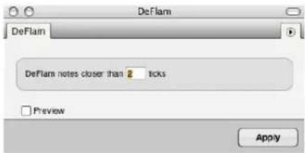
Figure 48-26: DeFlam.
The group of notes that is deflammed is determined by the tick value you specify. This creates a “window” of effectiveness. Groups of notes within that window will be deflammed.
DeFlam basics
When chords are played in real time, the attacks of individual notes are often splayed as in the example below, which shows two four-note chords:
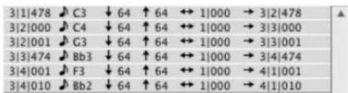
DeFlam is useful for consolidating the attacks of the notes in such chords. The following is the result of using DeFlam with a tick value of 50 on the above passage:

The quarter notes are now grouped into two precise chords.
DeFlam averages the attack times of the groups of notes; there is no grid involved as there is with the Quantize command. In the above example, the resulting attack time of each chord is the average of the attack times of the four original notes. The durations of the notes are left unchanged.
DeFlam attempts to detect grace notes and rolled chords and, if found, will leave them as such.
Using DeFlam
If DeFlam leaves some notes out, try using a larger tick value; if it includes too many notes, try decreasing the tick value. (Remember, you can Undo and Redo the DeFlam command.) The correct tick value depends greatly on the particular passage you are working with. It may take several attempts to determine the correct value.
CHANGE VELOCITY
Change Velocity is a powerful command that lets you modify the velocities of all MIDI notes in a region on a scale from 0-127. You can remove irregularities, make passages louder or softer and create crescendos, diminuendos and other similar effects. Note that not all MIDI instruments respond to velocity data, and those that do may need to be set up to respond correctly to this information. Consult your owner's manuals for details.
The Change Velocity window provides a menu with numerous options. These options are explained briefly in the following sections.
Change Velocity has no effect on audio.
On velocities or off velocities
On velocities control the speed at which a note is attacked. This affects the note's loudness most dramatically, but on velocities can also affect other aspects of the note event such as its timbre (e.g. the harder the note is struck, the brighter it sounds). Off velocities control the speed of the release of the note and are sometimes used to control its decay rate. Not all MIDI instruments utilize off velocity information.
The Change Velocity command can be applied to either on or off velocities: choose the type you wish at the top of the window. The default setting changes the on velocities.
Set
This option sets all velocities in the selected region to a single value. Enter a value between 1 and 127. A result of this option is that all note events in the region will be played back at a constant volume.
Add
This option adds the value you enter to all velocities in the selected region. The value must be in the range -127 to 127. Velocities that end up less than 0 or greater than 127 will be set to zero or 127, respectively. A result of this option is a uniform increase or decrease in volume of all notes in the region, within the zero to 127 range.
Scale
This option scales all velocities by the percentage value you enter. Percentage values must be between 1 and 999. For example, if all notes in the region have a velocity of 120 and you enter a percentage value of 50%, the velocities will be set to 60. Thus, to halve velocities, use a value of 50%. To double them, use 200%. Velocities that end up less than 0 or greater than 127 will be set to zero or 127, respectively.
Scaling by a percentage may give you better results than using the Add ____ to all velocities option above since the original velocity contours are preserved. Try both to discover which gives you the results you want.
Limit
This option modifies all velocities in the selected region that have a velocity greater than the value you enter, by changing them to that value. Enter a value between 1 and 127. This option imposes a
maximum volume level on all notes in the region. You can use it to change the velocities of notes that "stick out".
Compress/Expand
This option works just like an audio compressor or expander: it reduces or expands the velocities above the threshold you specify by the compression ratio you specify, and then adds any gain that you specify with the gain control. The graph shows a visual display of the current compression settings on a 128 x 128 grid, so you can see exactly how velocities from 0 to 127 will be affected.

Figure 48-27: Graphic control over compression and expansion settings.
Expansion multiplies velocities by the ratio that you choose. Compression divides them. Velocity expansion or compression can be useful in many situations. For example, if you change the patch for a track, the new patch may have different velocity response characteristics than the original patch, and as a result, the track may not sound as expressive. By applying expansion to the note velocities, you can restore—or even magnify—the original expressiveness of the track. Ratios up to 1:8 are offered.
Smooth
This option has two basic sub-options: ____% to ____% of current value and ____ to ____. Each gives you a different way to specify the smooth velocity changes. The first changes by percentages, creating a smooth velocity change for notes in the selected region while preserving some of the original velocity characteristics (most notably the accents); the second creates a smooth change with no fluctuations. You can specify a curvature for the change, which determines its contour.
____% to ____% of current value: This sub-option changes velocities similarly to the Scale option described above. The difference is that the percentage value changes from the first to the second entered value: the first value applies to the beginning of the region, the second to the end. Enter a value from 1 to 999 in each box. The curvature (see below) controls the contour of the change.
____ to ____: This sub-option assigns the first entered value to the first note velocity in the selected region and the second entered value to the last note velocity in the region. All other velocities are calculated to make a smooth transition between the first and last ones. The curvature (see below) controls the contour of the change over the region.
Curvature: This sub-option controls the contour of the smooth change. With a curvature of zero, the change is linear from the first to the second entered value. As you increase the value positively (with values from 1 to 99), more of the change will take place towards the end of the region. As you increase the value negatively (with values from -1 to -99), more of the change will take place towards the beginning of the region.
Here are a few examples to clarify this option:
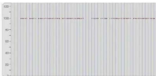
Figure 48-28: Change smoothly from 1 to 90, curvature 0. This results in a linear increase. One effect of this is a gradual, even crescendo.

bar
| Category | Value | |---|---| | 1 | 10 | | 2 | 20 | | 3 | 30 | | 4 | 40 | | 5 | 50 | | 6 | 60 | | 7 | 70 | | 8 | 80 | | 9 | 90 | | 10 | 100 | | 11 | 110 | | 12 | 120 | | 13 | 130 | | 14 | 140 | | 15 | 150 | | 16 | 160 | | 17 | 170 | | 18 | 180 | | 19 | 190 | | 20 | 200 | | 21 | 210 | | 22 | 220 | | 23 | 230 | | 24 | 240 | | 25 | 250 | | 26 | 260 | | 27 | 270 | | 28 | 280 | | 29 | 290 | | 30 | 300 | | 31 | 310 | | 32 | 320 | | 33 | 330 | | 34 | 340 | | 35 | 350 | | 36 | 360 | | 37 | 370 | | 38 | 380 | | 39 | 390 | | 40 | 400 | | 41 | 410 | | 42 | 420 | | 43 | 430 | | 44 | 440 | | 45 | 450 | | 46 | 460 | | 47 | 470 | | 48 | 480 | | 49 | 490 | | 50 | 500 | | 51 | 510 | | 52 | 520 | | 53 | 530 | | 54 | 540 | | 55 | 550 | | 56 | 560 | | 57 | 570 | | 58 | 580 | | 59 | 590 | | 60 | 600 | | 61 | 610 | | 62 | 620 | | 63 | 630 | | 64 | 640 | | 65 | 650 | | 66 | 660 | | 67 | 670 | | 68 | 680 | | 69 | 690 | | 70 | 700 | | 71 | 710 | | 72 | 720 | | 73 | 730 | | 74 | 740 | | 75 | 750 | | 76 | 760 | | 77 | 770 | | 78 | 780 | | 79 | 790 | | 80 | 800 | | 81 | 810 | | 82 | 820 | | 83 | 830 | | 84 | 840 | | 85 | 850 | | 86 | 860 | | 87 | 870 | | 88 | 880 | | 89 | 890 | | 90 | 900 | | Note: The 'Value' in the 'Value' column is the sum of all other columns (e.g., 'Value' = 'Value' * 'Value' * 'Value' * 'Value' * 'Value' * 'Value' * 'Value' * 'Value' * 'Value' * 'Value' * 'Value' * 'Value' * 'Value' * 'Value' * 'Value' * 'Value' * 'Value' * 'Value' * 'Value' * 'Value' * 'Value' * 'Value' * 'Value' * 'Value' * 'Value' * 'Value' + 'Value' * 'Value' * 'Value' * 'Value' * 'Value' * 'Value' * 'Value' * 'Value' * 'Value' * 'Value' * 'Value' * 'Value' * 'Value' * 'Value' * 'Value' * 'Value' * 'Value' * 'Value' * 'Value' * 'Value' * 'Value' * 'Value' * 'Value' * 'Value' * 'Value' / 'Value' * 'Value' * 'Value' * 'Value' * 'Value' * 'Value' * 'Value' * 'Value' * 'Value' * 'Value' * 'Value' * 'Value' * 'Value' * 'Value' * 'Value' * 'Value' * 'Value' * 'Value' * 'Value' * 'Value' * 'Value' * 'Value' * 'Value' * 'Value' * 'Value' .Figure 48-29: Change smoothly from 10 to 90, curvature -50. This results in a pronounced upward curve with most of the changes happening at the beginning. One effect of this is a crescendo that occurs more rapidly at the beginning.
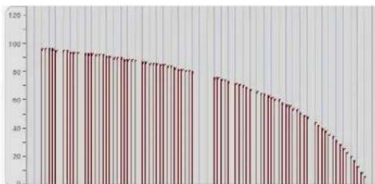
bar
| Category | Value | |---|---| | 1 | 98 | | 2 | 97 | | 3 | 96 | | 4 | 95 | | 5 | 94 | | 6 | 93 | | 7 | 92 | | 8 | 91 | | 9 | 90 | | 10 | 89 | | 11 | 88 | | 12 | 87 | | 13 | 86 | | 14 | 85 | | 15 | 84 | | 16 | 83 | | 17 | 82 | | 18 | 81 | | 19 | 80 | | 20 | 79 | | 21 | 78 | | 22 | 77 | | 23 | 76 | | 24 | 75 | | 25 | 74 | | 26 | 73 | | 27 | 72 | | 28 | 71 | | 29 | 70 | | 30 | 69 | | 31 | 68 | | 32 | 67 | | 33 | 66 | | 34 | 65 | | 35 | 64 | | 36 | 63 | | 37 | 62 | | 38 | 61 | | 39 | 60 | | 40 | 59 | | 41 | 58 | | 42 | 57 | | 43 | 56 | | 44 | 55 | | 45 | 54 | | 46 | 53 | | 47 | 52 | | 48 | 51 | | 49 | 50 | | 50 | 49 | | 51 | 48 | | 52 | 47 | | 53 | 46 | | 54 | 45 | | 55 | 44 | | 56 | 43 | | 57 | 42 | | 58 | 41 | | 59 | 40 | | 60 | 39 | | 61 | 38 | | 62 | 37 | | 63 | 36 | | 64 | 35 | | 65 | 34 | | 66 | 33 | | 67 | 32 | | 68 | 31 | | 69 | 30 | | 70 | 29 | | 71 | 28 | | 72 | 27 | | 73 | 26 | | 74 | 25 | | 75 | 24 | | 76 | 23 | | 77 | 22 | | 78 | 21 | | 79 | 20 | | 80 | 19 | | 81 | 18 | | 82 | 17 | | 83 | 16 | | 84 | 15 | | 85 | 14 | | 86 | 13 | | 87 | 12 | | 88 | 11 | | 89 | 10 | | 90 | -1 | | -90 | -10 | | -91 | -9 | | -92 | -8 | | -93 | -7 | | -94 | -6 | | -95 | -5 | | -96 | -4 | | -97 | -3 | | -98 | -2 | | -99 | -1 | | -100 | -0.5 (with label 'a' in the image) for the last three categories. The chart displays a descending trend from left to right. The y-axis represents the numerical value of the first three categories, and the x-axis represents the category labels. The data is presented in a single column format with two columns: 'Category' and 'Value'.Figure 48-30: Change smoothly from 96 to 5, curvature 45. This results in a downward curve which is more pronounced at its end, e.g. a diminuendo that speeds up toward its end.

bar
| Category | Value | |---|---| | 1 | 100 | | 2 | 95 | | 3 | 90 | | 4 | 85 | | 5 | 80 | | 6 | 75 | | 7 | 70 | | 8 | 65 | | 9 | 60 | | 10 | 55 | | 11 | 50 | | 12 | 45 | | 13 | 40 | | 14 | 35 | | 15 | 30 | | 16 | 25 | | 17 | 20 | | 18 | 15 | | 19 | 10 | | 20 | 5 | | 21 | 0 | | 22 | 0 | | 23 | 0 | | 24 | 0 | | 25 | 0 | | 26 | 0 | | 27 | 0 | | 28 | 0 | | 29 | 0 | | 30 | 0 | | 31 | 0 | | 32 | 0 | | 33 | 0 | | 34 | 0 | | 35 | 0 | | 36 | 0 | | 37 | 0 | | 38 | 0 | | 39 | 0 | | 40 | 0 | | 41 | 0 | | 42 | 0 | | 43 | 0 | | 44 | 0 | | 45 | 0 | | 46 | 0 | | 47 | 0 | | 48 | 0 | | 49 | 0 | | 50 | 0 | | 51 | 0 | | 52 | 0 | | 53 | 0 | | 54 | 0 | | 55 | 0 | | 56 | 0 | | 57 | 0 | | 58 | 0 | | 59 | 0 | | 60 | 0 | | 61 | 0 | | 62 | 0 | | 63 | 0 | | 64 | 0 | | 65 | 0 | | 66 | 0 | | 67 | 0 | | 68 | 0 | | 69 | 0 | | 70 | 0 | | 71 | 0 | | 72 | 0 | | 73 | 0 | | 74 | 0 | | 75 | 0 | | 76 | 0 | | 77 | 0 | | 78 | 0 | | 79 | 0 | | 80 | 0 | | 81 | 0 | | 82 | 0 | | 83 | 0 | | 84 | 0 | | 85 | 0 | | 86 | 0 | | 87 | 0 | | 88 | 0 | | 89 | 0 | | 90 | 0 | | 91 | 0 | | 92 | 0 | | 93 | 0 | | 94 | 0 | | 95 | 0 | | 96 | 0 | | 97 | 0 | | 98 | 0 | | 99 | 0 | | Note: The 'Value' in the 'Value' column is the sum of all other columns from the 'Value' column to the 'Value' column in the 'Value' column. The 'Number' in the 'Number' column is also included in the data but not explicitly labeled on the 'Value' column.Original velocities

line
| X | Y | |---|---| | 1 | 100 | | 2 | 95 | | 3 | 90 | | 4 | 85 | | 5 | 80 | | 6 | 75 | | 7 | 70 | | 8 | 65 | | 9 | 60 | | 10 | 55 | | 11 | 50 | | 12 | 45 | | 13 | 40 | | 14 | 35 | | 15 | 30 | | 16 | 25 | | 17 | 20 | | 18 | 15 | | 19 | 10 | | 20 | 5 |Scale smoothly from 100% to 1% with 0 curvature
Figure 48-31: Scale smoothly from 100% to 1%, curvature 0. When applied to a region in which there are several notes accented, this results in a downward "curve", which retains the accent structure of the original.
The velocity values assigned to notes by this option are calculated based on the distance of the note from the beginning or end of the selected region. If the first note in the region is after the start time, for instance, it will be assigned a velocity value somewhere between the values entered. Notes in a chord (with simultaneous attacks) are assigned the same velocity. If a specific change sounds too abrupt, it is probably due to the position of the note in the region. For instance, if notes occur at irregular times (e.g. bunched together followed by a sparse section), velocities will be assigned on the basis of note placement. The result may not seem smooth on a per-note basis.
Randomize
The randomize option allows you to randomize the velocities within a range of the current value, which you specify in the box provided. The emphasis sub-option causes the tendency of the randomization to be higher or lower within the specified range. Thus, if you wish to randomize the velocities within a certain range, but you wish
them to tend to be higher, use a positive emphasis; use a negative emphasis if you wish them to tend to be towards the lower end of the range. A value of zero equals no emphasis, which causes the randomization to occur evenly within the range.
Note that the randomize option is a check box, which means that it can be selected together with one of the radio button options above. This allows you to randomize at the same time as executing one of the other Change Velocity options.
The effect of velocity is instrument-dependent
MIDI instruments vary widely in their response to velocity information. Some do not respond at all to any velocity information; many do not respond to off velocities. Some patches sound very different when large on velocity values are used. Some patches do not respond at all to velocity information, even when the instrument as a whole does.
Most often, you can be assured that if your instrument does respond to velocity information, you can control the loudness of note events. You should be able to create effective crescendos and diminuendos. This will work well for short-range dynamic effects. For longer effects (a 30 second fade, for instance), you might notice a “staircase” effect, i.e. discrete changes in the volume level.
Alternative methods for volume changes
Some MIDI instruments define one of the MIDI controllers as the volume control. If so, you might be able to use the Insert Continuous Data command to create smooth volume changes with a controller. Some instruments have only a few discrete volume levels, making it hard to create smooth changes. Consult the Hints in the Event List section for details about determining the limits of the controller values on your instrument.
It is also possible with some instruments to control volume directly from an assignable controller. A patch may use the breath controller to control its volume, for instance. By sending this controller data through Digital Performer, you can control volume changes.
There is no single solution for making volume changes effectively with every patch on every instrument. You must find the best way for each given situation and use the appropriate command (Change Velocity or Insert Continuous Data) to create the kind of volume changes you want.
CHANGE DURATION
The Change Duration command modifies the duration of all MIDI notes in the selected region without changing the placement of attack times. This means that the amount of time a note is “on” or sounding can be changed without affecting its actual rhythmic placement in relation to other notes and events. The Change Duration command is useful for changing the articulation or space between notes. You can make note events sound connected or separate in relation to each other, for example.

Figure 48-32: Change Duration.
Changing the duration of soundbites
The Change Duration command does not affect soundbites. To change the duration of a soundbite, trim it as explained in “Trimming (edge editing) soundbites” on page 393. To stretch it, see “Graphic time stretching of audio” on page 396 or “Scale Time” on page 639.
Change Duration basics
Duration is the length of a note, i.e. the time between its attack and release. Durations are specified in quarter notes and ticks (e.g. a half note would be 2|000 or two quarter notes). A note must have a duration of at least one tick (0|001).
A note's duration may be misleading in some cases: what you see might not be what you hear. The actual duration of a note event is dependent upon the MIDI instrument and patch used. The attack and release sent by Digital Performer are equivalent to manually pressing and releasing a key on the instrument. Also, some instruments have a sustain pedal that can be used to hold notes, extending the effective duration of notes far beyond the time when the release has been sent to the instrument.
Set
All durations in the selected region will be changed to the entered value. The value entered must be between 0|001 and 9999|999.
Add
The value entered will be added to all durations in the selected region. The value entered must be between 0|001 and 9999|999.
Subtract
The value entered will be subtracted from all durations in the selected region. The value range is 0|001 and 9999|999. Notes which would have a duration of less than one tick after the subtraction are given a duration of one tick.
Scale
The durations of notes in the selected region are scaled by the entered percentage value. The relative lengths of the notes are preserved and their overall length is modified. The percentage value entered must be between 1 and 999. To halve durations, enter a percentage value of 50%; to double durations, use 200%. Using this option may yield more of the results you want than using the Add _ to all option; durations are scaled proportionally instead of uniformly lengthened. Try both to see which you like best.
Limit
Any notes in the selected region which have a duration greater or less than the values entered will be assigned to the longest and shortest value you specify, respectively. The value entered must be between 0|001 and 9999|999.
Move releases (to closest attack)
The release of each note in the selected region is modified to occur just before the attack of the nearest note following it in time. The duration of
the note may increase or diminish depending on when the next note occurs. If the next note occurs before the release of the current one, the release of the current note will be moved back in time, making the duration shorter. If the next note occurs after the release of the current one, the release of the current one will be moved forward in time, making the duration longer. If the note release is after the end of the selected region, the note is left unmodified. This option creates a legato effect, where the notes follow each other smoothly and without a gap.
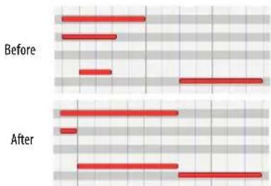
Figure 48-33: Move releases to closest attack.
Extend releases (to the closest attack)
The duration of each note in the selected region is extended until it ends at the same time as the next note begins. This is very similar to the Move releases to the closest attack option but the durations of all notes are guaranteed to increase since the release is always moved forward in time. Any notes which end after the last note in the selected region begins are left unmodified.
This option creates a legato effect, where the notes follow each other smoothly and without a gap.

Figure 48-34: Extend releases to closest attack.
Extend Releases sub-options
Use these sub-options to extend releases and still preserve rests in a region. If both sub-options are checked, each note in the region is analyzed and the option that results in the smallest duration increase is used. Try using these options after quantizing attacks and releases to improve the notational display of the notes. Doing so adjusts the durations of notes that were not played in a legato style. For best results, experiment with different values. A good setting to start with is 100%.
Randomize
The randomize option allows you to randomize durations within a range of the current duration, which you specify in the box provided. This range can be specified as an absolute number of ticks, or by a percentage of the current duration. The emphasis sub-option causes the tendency of the randomization to be higher or lower within the specified range. Thus, if you wish to randomize the durations within a certain range, but you wish them to tend to be longer, use a positive emphasis; use a negative emphasis if you wish them to tend to be shorter. A value of zero equals no emphasis, which causes the randomization to occur evenly within the range.
Note that the randomize option is a check box, which means that it can be selected together with one of the radio button options above. This allows you to randomize at the same time as executing one of the other Change Duration options.
Hints
Some drum machines cannot receive dense bursts of MIDI data; they will often miss data altogether, causing drop-outs and other perplexing problems. Since the durations of drum machine events tend to be very short, the note releases tend to follow the attacks very quickly resulting in a very high data density. A problem also arises with Step Record: the release for each note is sent immediately before the attack of the next note. One way to improve the situation is to delay the note releases (most drum machines ignore these anyway since their note events have such short decays) by making the note durations longer. Use the Change Duration command to set the durations of these note events to a value somewhere around 10 to 20 ticks.
Using Change Duration to control articulation
The Change Duration command is very good for adjusting the articulation of note events.
Rendering a passage legato or staccato is simple: for a legato effect (each note releasing just before the next one is attacked):
1 Select the region.
2 Choose Change Duration from the Region menu.
3 Choose the Set option.
4 Enter a value of 1 tick (0|001) and press Apply.
This insures that durations are uniform for the next step.
5 Choose Change Duration from the Region menu.
6 Choose the Extend releases option and press the Apply button.
This is useful for removing any rests or gaps between notes.
For a staccato effect (each note releasing well before the next, giving the passage a rhythmically sharp, incisive character):
1 Select the region.
2 Choose Change Duration from the Region menu.
3 Choose the Scale option.
4 Enter a value of 50% and press the Apply button.
If you enter a part in Step Record, all durations will be as long as specified, rendering a legato effect. You can use the Change Duration command to add the articulation you want to these parts.
SPLIT NOTES
The Split Notes command lets you selectively cut or copy notes in the selected region. The selection is based upon pitch, velocity and/or duration. This means that only notes with specific pitches, ranges, durations and velocities from the selected region are cut or copied. For example, all notes between A3 and C#3 with velocities greater than 100 and with durations above a half note can be extracted from a region. Here are some additional things you can do with Split Notes:
■ Use an on-screen graphic keyboard to specify the pitches of notes you wish to split. This keyboard allows you to pick a non-contiguous range of pitches for splitting.
■ Automatically Paste or Merge the split notes to a pre-existing track.
■ Automatically create a new track and Paste the split notes to it.
■ Automatically create a set of new tracks and paste the split notes to each track according to pitch.
Split Notes can be used to split a drum track into separate tracks, extract or double a melody line, separate one keyboard part into two parts to segregate right and left hand activity, pick out and double accented or long tones, and much more.
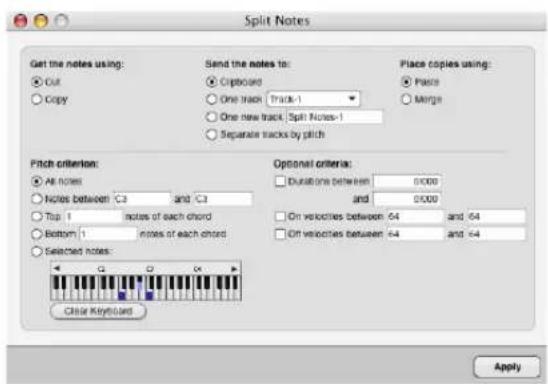
Figure 48-35: split Notes.
Split Notes basics
Split Notes is a highly specialized version of the Cut and Copy commands on the Edit menu. Only notes in the selected region and with specific properties are affected, other events are not affected. Each note is tested to see if it meets the requirements you specify, including velocity, pitch, and duration. They are then placed in a destination you select, such as the Clipboard or a new track. If cut, they are removed from the selected region.
The Split Notes window remembers the settings you last chose.
Cut or Copy
If you choose the Cut option, the Split Notes command will place the selected notes on the Clipboard and remove them from the selected region. If you choose the Copy option, the Split Notes command will place the selected notes on the Clipboard without removing them from the selected region.
Send notes to
You have several choices here. Select the Clipboard option to place notes on the Clipboard (for the purpose of pasting afterwards). Select the One track option and select a track name from the menu to send the notes to one existing track. Select the One new track option and type in a name or use the default name to send the notes to a new track that will be added to the bottom of your Track List. Select the Separate tracks by pitch option to remove the notes by pitch and place them into new, individual tracks. Each new track will contain the pitch name in parentheses after the track name. The track name used for this option can be entered in the One new track option text entry box above. This last option is ideal for splitting up a drum track into separate tracks.
Paste or Merge
These options let you choose whether you would like the split notes to be pasted at their destination, which replaces what is already there, or merged together with what is already there.
All Notes
All notes will be cut or copied unless excluded by velocity or duration selections. Use this mode when you wish to cut or copy notes based solely on velocity or duration criteria.
Range of Pitches
All notes between the two entered pitch values will be cut or copied. The pitch range is inclusive (it includes the two entered pitch values and all notes between them). You must enter a pitch in each box for this option.
You can enter pitch and velocity values directly from your MIDI keyboard. The note you play will be entered directly into the value box which contains the flashing text cursor or is highlighted.
Top \_\_\_\_ notes
The specified number of notes from the top of each chord are cut or copied. A chord is defined as two or more notes which have the same attack times. If single notes are encountered (i.e. not in chords), they alone are copied to the Clipboard. It is useful to use the DeFlam command on the Region menu to make sure that attack times of all chords line up before using this option. Enter the number of notes to be cut or copied from the top of each chord in the box for this option.
Bottom \_\_\_\_ notes
This option is similar to Top ____ notes except that the notes are cut or copied from the bottom of each chord.
Select notes
Click keys on the keyboard to select and deselect specific pitches. Click Clear Keyboard to clear the currently selected pitches on the keyboard. Use the scroll bar and scroll arrows to select pitches that are above or below those pitches which are currently displayed. You can also play keys on your MIDI keyboard (or other controller) to select and deselect specific pitches.
The Select notes keyboard remembers the selected notes even when those notes are scrolled to the left or right and are not displaying. When you open the dialog and want to select some pitches on the keyboard and are not sure if there are selected notes above or below the pitches that are currently displayed, click Clear Keyboard to be sure that notes that are not displayed are also not selected.
The following are velocity and duration options that can be selected in addition to pitch options.
Durations
Notes in the selected region with durations within the specified range are cut or copied. You must enter two durations in the boxes from 0|001 to 9999|999. The duration range is inclusive (it includes the two entered duration values and all those between them).
On velocities
This option, when selected, allows only notes with the specified velocity range to be cut or copied from the selected region. You must enter two velocities (between 1 and 127) in the two boxes. The velocity range is inclusive (it includes the two entered values and all those between them).
Off velocities
This mode is similar to the On velocities mode except that notes with off velocities in the specified range are cut or copied.
Hints for using Split Notes
The Split Notes command by itself is not always completely useful: it can be used in conjunction with other region commands and operations to fully accomplish an editing task. We therefore have included some effective ways to use the Split Notes command as part of more complex operations.
Splitting up a drum part into separate tracks
You can use the Separate tracks by pitch option in combination with the Select notes option to quickly explode tracks such as drum parts into separate tracks so that each pitch can be treated uniquely. This is great for being able to shift, quantize and otherwise edit a certain percussion instrument without affecting others.
Using a temporary track
You can process data independently that is cut or copied with the Split Notes by pasting it into another track. You can perform various operations on the data in the temporary track (transpose, velocity editing, etc.), then merge it back into the original track and delete the extra track.
Extracting a lead line
Extracting the lead line from a passage (perhaps from block chords where the top notes of each chord form a melody) can be easily done with the Split Notes command. After the lead line is separated from the chords, it can be modified (doubled, accented or otherwise enhanced) in an extra track.
Enhancing a lead line
After you have the lead line separated out, you can change it in useful ways. Two suggested enhancements are doubling it an octave higher and increasing its velocity values. After you have made the modifications, you can merge the enhanced lead line back with the original material.
A variation on the operation to double the lead line an octave higher is to double the bass line an octave lower. Use the Bottom ____ notes option and transpose it down an octave with the Transpose command.
Some variations on the operation to increase the velocity values of the lead line are as follows:
Make the notes of the chords softer (by decreasing their velocities) instead of the making the lead line louder. This would involve modifying the notes of the chords after you extracted the lead line from them and merging the (unaltered) lead line back with the modified chords.
Use the Change to ____% of current value option in the Change Velocity window rather than adding a constant value to the lead line. This better preserves the dynamic contour of the lead line.
Leave the lead line on a separate track and play it back through another MIDI instrument as well as on the instrument playing back the chords. This highlights the lead line through timbral or tone color means.
Doubling accented notes
Another procedure is to split out only those notes which have a higher velocity in order to accent them. After extracting them with Split Notes, use other Region commands (such as Transpose) to enhance the accented notes. Alternatively, you can simply assign the track with only the accented notes to be played back on a separate channel by another MIDI instrument.
Dividing a keyboard part into its right and Left hand components
Sometimes, it is useful to be able to treat the left-hand and right-hand parts of a keyboard track separately. Digital Performer does this automatically in the QuickScribe Editor. If you want, you can do it manually by following the earlier procedure for extracting a lead line but use the Notes with pitches between ____ and ____ option. The pitches you enter should correspond with the range of either the right or left hand. Since this range is rarely consistent, you will probably have to organize your sequence into sections according to one hand's pitch range and use Split Notes on each section. You can then add a new track and paste the notes you've cut into it.
INVERT PITCH
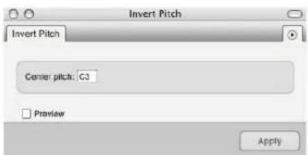
Figure 48-36: Invert Pitch
The Invert Pitch command inverts or flips MIDI notes around a specified axis. The inversion is chromatic, that is, exact. For example, if the following E major scale (starting on E3),

is inverted around an axis of D3, the following will result:

Basics
Inversion is an operation in which the interval between a note and the inversion axis pitch is measured and the note is transposed the same interval on the opposite side of the axis pitch. Two examples are shown below: If the note to be inverted is F4 and the axis pitch is C4, the interval between them is a perfect fourth. Since F4 is above C4, it will be transposed down by the same interval, a perfect fourth, resulting in a G3. If the note to be inverted is C#3 and the axis pitch is A3, the resulting pitch would be F4. In the following picture, the axis pitch in each measure is represented by a diamond:

The inversion is always exact, transposing the note the same chromatic interval above or below the axis pitch.
Hints
You can invert a region of notes around a pair of axis pitches. Follow the above procedure for normal inversion specifying the lower of the two pitches in the Invert Pitch window. Then use the Transpose command on the Region menu to transpose the region by the interval between the two axis pitches.
Example: You wish to transpose the following passage around the axis pitch pair C3 and E flat 3.

Use Invert Pitch on the passage specifying C3. The following is the result:

Select the region containing the passage and use the Transpose command on the Region menu transposing from C3 to E flat 3 (a minor third, the interval between the two axis pitches).
This is the final result, inverted correctly around the pair of axis pitches:

MIDI EFFECTS PLUG-INS
The MIDI Effects Plug-ins hierarchical menu supplies “special effects” processing to your MIDI tracks. These are plug-ins that can be applied to your MIDI tracks in the same fashion as Digital Performer’s standard Region menu operations.

Figure 48-37: MIDI Effects plug-ins in the Region menu. These first few effects (Echo, Arpeggiate, etc.) are not actually plug-ins. They are special effects made available as Region operations. Therefore, you will not see them in Digital Performer's 'Plug-ins' Folder.
Using MIDI Effects plug-ins
MIDI Effects plug-in windows look very similar to Digital Performer's other Region menu commands. In fact, some — like the Transpose and Shift plug-ins — are virtually identical to Digital Performer's corresponding Region and Edit menu commands.

Figure 48-38: Examples of Digital Performer's MIDI effects plug-ins.
Apply the MIDI effects plug-ins in the same fashion as other Region menu commands.
For details regarding the options in the Transpose plug-in window, see "Transpose" on page 594.
For details regarding the options in the Echo and Arpeggiate effects, see “Echo and Arpeggiator” on page 912.
For details regarding the options in the Remove Duplicates effect, see “Remove Duplicates” on page 918.
For details regarding the options in the Reassign Continuous Data effect, see "Reassign Continuous Data" on page 918.
Real-time MIDI effects processing
MIDI Effects plug-ins can also support Digital Performer's real-time MIDI effects processing in the Mixing Board. If the plug-in supports real-time processing, it will automatically appear in the effects inserts of MIDI tracks in the Mixing Board window. If the plug-in appears in the Region menu, but not in the Mixing Board inserts, then it doesn't support real-time operation. Real-time operation has the advantage of not permanently altering the data in the track. It only alters the data during playback.
THE CONTINUOUS DATA COMMANDS
Continuous data is audio mix automation data or MIDI data which changes smoothly over time. Audio continuous data types include volume and pan mix automation, plug-in parameter automation, etc. Continuous MIDI data types include pitch bend, mono and poly key pressure and controller information. These types of data are output rather quickly, resulting in a large amount of data. Continuous data events are closely spaced, each specifying a slightly different value for the parameter which is changing. For instance, when you move a pitch wheel, a different pitch bend value might be sent every 20 ticks, resulting in 120 continuous data events per quarter note.
MIDI continuous data is not really continuous at all: it is approximated by large numbers of events, each of which contain a small value change. When played back, they create a change that seems smooth and continuous. The closer together in time successive values are, the smoother the change will be. If the values are too close together, delays can occur due to the baud rate (data transfer speed) limit of MIDI transmission.
There are 16,384 different pitch bend values and 128 different controller and aftertouch values. Some MIDI instruments do not respond to every different pitch bend value: several successive values may produce the same effect. The response to different controller values may also be hard to hear. These facts may influence your decision about how many continuous data events to store. Digital Performer gives you the option to decrease or increase the number of continuous data events in a region.
Types of MIDI continuous data
The continuous data commands require you to specify the type of continuous data to be modified. The following is a description of the different types of MIDI continuous data and how they are produced.
Pitch Bend: On most MIDI instruments, this is controlled by a wheel, joystick or ribbon controller. When moved, it “bends” or varies the pitch either up or down depending on the direction of movement. Pitch bend data indicates the movement of the pitch bend device; it does not necessarily correspond to a musical interval. When played back, this data controls the sound module’s pitch bend device. Most instruments allow you to specify the interval by which a maximum pitch bend value will alter a pitch. Thus, moving the pitch bend device to its extreme high position could cause a pitch to be raised by an octave, a fifth or any other interval. All other pitch bend values are scaled according to the interval the maximum value produces.
Mono key pressure: Also known as aftertouch or channel pressure, this is a special kind of controller, which sends out values between zero and 127. If you continue to press down a key after you play a note, mono key pressure information is sent. The harder you press, the higher the value. Mono key pressure is useful for things like changing the tone quality of a sound or controlling the amount and depth of vibrato.
Poly key pressure: This is similar to mono key pressure except that each key can generate its own pressure information, instead of one pressure level for the whole instrument based on the key most recently pressed. Poly key pressure therefore allows for much more subtle and complicated aftertouch effects. Since each key can have its own set of key pressure data, you must specify the note name by entering a pitch value when using the Poly key pressure option in the continuous data commands. You can enter the pitch directly from your MIDI keyboard. If you don't specify a pitch, all keys will be affected by the command.
Controller: Foot pedals, wheels, sliders and breath controllers are common types of controller devices. Controllers are general purpose messages used to control such effects as vibrato and tremolo. They are identified by number; the number assigned to a specific controller depends on the MIDI instrument you are using. Continuous controllers (such as wheels and sliders) are generally numbered in the range zero to 63. Switch controllers (on-off types like a sustain pedal) use higher numbers. Instruments will often respond to more controllers than they have physical controls for.
When using the continuous data commands on controller messages, you must specify the number of the controller whose data you wish to modify. This can be done by clicking in the box next to the controllers option and moving the correct controller on your MIDI input keyboard.
THIN CONTINUOUS DATA
MIDI instruments tend to send continuous data as fast as they possibly can. If you record several tracks of this and play them all back at once, Digital Performer, your instruments, or MIDI itself may bog down. The Thin Continuous Data command selectively removes continuous data events, “thinning out” the amount of continuous data while retaining all of its essential characteristics. This allows you to transmit a reasonable amount of continuous data that can be handled easily by all components of your MIDI system.

Figure 48-39: Thin Continuous Data
The Thin Continuous Data command actually determines the contour of the continuous data in the selected region. The continuous data in this region is erased and new continuous data is generated. This new data is more sparse, reconstructing the analyzed contour with fewer events. Unless musically necessary, successive continuous data events will not occur closer together than the minimum time change and will not differ in value from adjacent events by less than the minimum value change.
Since the continuous data is regenerated, it is possible that this command will thicken the data instead of thinning it. You may find this aspect of the command useful if you have thinned out the data too much.
The appropriate minimum time change depends on the tempo of the sequence and the controller device involved. Generally, a value of 10 to 20 will work well. The minimum value change should be 1 for controllers and 4 to 8 for pitch bend. Experimentation is essential to find the best values in each instance.
INSERT CONTINUOUS DATA
The Insert Continuous Data command creates a stream of continuous data events that change smoothly over time. You can use it to create pitch bends, crescendos and diminuendos, filter sweeps and many other effects.
This command creates continuous data events that change smoothly between the starting and ending values. All values must be within the range zero to 127, except for pitch bend data which is in the range -8192 to 8191. Data created by the Insert Continuous Data command will replace existing controller data of the same type.
The contour of the changing values is controlled by the curvature parameter. It allows you to "weight" the change. With a curvature of zero, the change is linear from the first to the second entered value. The more you increase the value positively (with values from 1 to 99), the more the change will take place towards the end of the region. The more you increase the value negatively (with values from -1 to -99), the more the change will take place towards the beginning of the region.
The number of events generated are controlled by the minimum time change and the minimum value specified: all events created will not be any closer together than the minimum time change and they won't be separated by values smaller than the minimum value change. Though Digital Performer can create a perfectly smooth set of values, the actual result may not be perfectly smooth due to the minimum time and value changes you enter. Experimentation is the key to good results.

Figure 48-40: Insert Continuous Data.
The Randomize option
The Randomize option allows you to generate variability in continuous data that you create, as opposed to a perfectly smooth line or curve. Doing so can introduce extra feel and depth to the musical effect you are creating with the continuous data.
Notice that the Randomize option is a check box, which means that it can be used with any of the radio button options above. Check the box to randomize; uncheck it for no randomization.
When this command randomizes, it chooses random values within the range that you specify. Each continuous data event is first generated by the rest of the parameters above, and then the event's value is randomized within the range you specify in the range box. The result is a curve or line that is not perfectly straight, as shown in Figure 48-41:
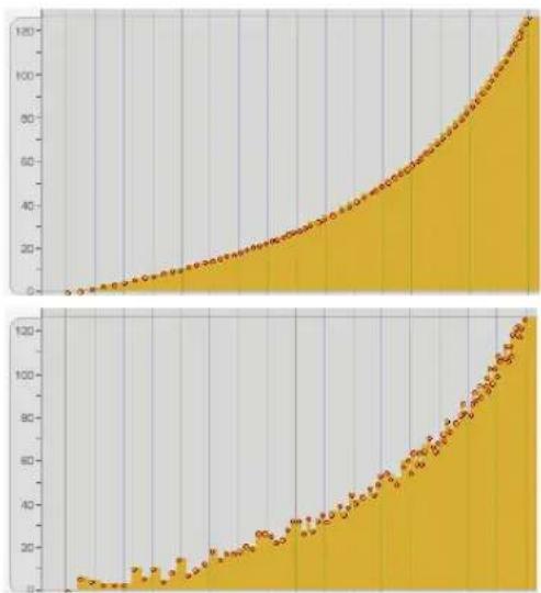
Figure 48-41: Here is a continuous data curve without randomization (above) and with a randomization of ± 6 (below).
Emphasis
The Emphasis sub-option causes the tendency of the randomization to be higher or lower within the specified range. Thus, if you wish to randomize the continuous data events within a certain range, but you wish them to tend to be higher, use a positive emphasis; use a negative emphasis if you wish them to tend to be towards the lower end of the range. A value of zero equals no emphasis, which causes the randomization to occur evenly within the range.
CHANGE CONTINUOUS DATA
With the Change Continuous Data command, you can modify existing continuous data by scaling it or limiting it to a specific range.

Figure 48-42: Change Continuous Data
For more information about the randomization options, see “The Randomize option” on page 636, as this option works the same as the Randomize option in the Insert Continuous Data command, except that it changes existing data rather than newly created data.
Add \_\_\_\_ to all values
The entered value is added to all continuous data in the selected region. Enter a positive number if you wish to increase the values in the region or a negative number if you wish to decrease them. If a value exceeds the limit of its data type, it will be truncated at the limit value (e.g. if a pitch bend value comes out to -10,150, it will become -8192, the minimum limit for pitch bend values).
Limit to a range from \_\_\_\_ to \_\_\_\_
Events in the selected region whose values are outside the range of values that you enter (lower than the from value and higher than the to value) are changed to those values.
Change to \_\_\_\_% of current value
The values of all events in the selected region are scaled by the entered percentage value. Thus, specifying 50% halves the values, and 200% doubles the values. If a value exceeds the limit of the its data type, it will be truncated at the limit value (e.g. if a pitch bend value comes out to -10,150, it will become -8192, the minimum limit for pitch bend values).
Create Stairsteps
Digital Performer supports ramp automation with plug-ins. If, for some reason, a situation calls for stair stepping, you can convert it into stair steps using the Create Stairsteps option.
Randomization
For information about the Emphasis option, see "Emphasis" on page 608.
REASSIGN CONTINUOUS DATA
With the Reassign Continuous Data command you can convert one type of continuous data into another. For example, you can convert pitch bend data into modulation wheel data. This command is very useful for changing the controller number of continuous data when playing back a sequence on a different instrument than the one it was recorded with.

Figure 48-43: Reassign Continuous Data
REVERSE TIME AND RETROGRADE
The Reverse Time and Retrograde commands reverse the order of MIDI events in a selected region. However, each command reverses notes in a slightly different way, producing much different results.
Reverse Time
Reverse Time reverses the order of notes' attack times in a region. A note whose attack occurs two beats from the beginning of the region is moved so that its attack occurs two beats before the end of the region. In doing so, Digital Performer either maintains the note's duration or ends the duration just before the next attack. Notice in the example below that Reverse Time places the attack of the first note exactly at the end of the region, extending the duration into the next measure.
Retrograde
Retrograde inversion simply reverses the order of notes within the region: the first note becomes the last note, the last note becomes the first note, and so on. This is analogous to playing a tape backwards and recording the result.
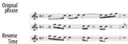
Retrograde
Note: for clarity, we have shortened the durations in the Reverse Time example so that they don't extend beyond the next attack. In actuality, the notes maintain their original durations after being reversed.
To get an exact reversal of the notes, you must select a region of time rather than specific events. In addition, the region of time must include the duration of the last note in the region. In the example above, the last note is the sixteenth note, G4. To obtain the results shown on the bottom staff, you would have to select the region from 1|1|000 to 2|1|000, where 2|1|000 takes into account the duration of the G4 sixteenth note.
To specify a region of time that includes the final duration, select the region using the Selection Information window, or by dragging in the Time Ruler of the MIDI Editor or Track Overview. Selecting specific events won't work because the duration of the final note is not included. (For example, if you selected the original phrase above in the Event List, the end of the region would be 1|4|361 instead of 2|1|000.
Using Retrograde
When using the Retrograde command, you must select a time range. The Retrograde command will have no effect on event selections. For details, see "Selecting a time range" on page 547 and "Edit operations that require time range selection" on page 547 for details.
SCALE TIME
The Scale Time command expands or compresses the duration of MIDI and audio events in the selected region by the length, end time, percentage or ratio (e.g. 2:3) that you specify. This effectively changes the distance between MIDI notes and soundbites, making them closer together or farther apart. Since the actual duration of events changes, the region will become smaller or larger after this command is invoked. If you check the Time-scale audio check box, then the actual waveform data inside the soundbites is “constructively” time-stretched, too. For details about constructive soundbite time stretching, see “Constructive editing” on page 922. For more information about time-scaling audio, see chapter 82, “Scale Time” (page 947).
The Scale Time command does not affect loops or any event in the Conductor track.
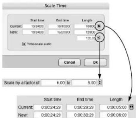
Figure 48-44: Scale Time.
Specifying the scale amount
To specify the amount of time by which to scale, you can type in the desired:
■ End time
■ Length
■ Percentage
■ Ratio
Entering a value in one of these fields automatically updates the three other fields.
When entering a ratio, if the first number in the ratio is larger than the second, the region is expanded; if the first number is smaller than the second, the region is compressed. A ratio of 2:1 doubles the duration of all events in the region (and doubles the length of the entire region as well); a ratio of 1:2 halves the duration of all events in the region. You can enter integer ratios with up to two decimal places.
Events at the Start time of the region will remain in place. Since the overall length of the region changes, events at the end will be moved. If the end of the region expands, events in it will be merged with data already there.

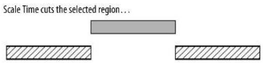

flowchart
graph TD
A["..."] --> B["...and then compresses and merges..."]
B --> C["Blank space"]

Figure 48-45: How Scale Time compresses or expands and then merges data.
Scale time examples
Here are three examples to give you a better idea of the use of Scale Time:
You've entered a melody in eighths but decided it would sound better in sixteenths. Select the region of the melody and use Scale Time with a ratio of 1:2.
Your sequence is in 4/4 time with lots of triplets, and you want to modify it to be in 12/8, converting the triplets to regular eighths. Select the entire sequence. Use Scale Time with a ratio of 3:2. Afterwards, change the meter and tempo appropriately.
You've entered a melodic idea in quarter notes and decide that it should actually be the bass line for the sequence — and all notes should be whole notes. Select the region with the melody and use Scale Time with a ratio of 4:1. Then transpose it down to the correct octave.
SCALE TEMPO
The Scale Tempo command provides several ways to modify existing tempos within a selected region in the Conductor track of a sequence or song. It modifies existing tempo events within the region, but it does not generate new tempo events. (To do so, use Project menu>Conductor Track>Change Tempo.) The Scale Tempo command is ideal for making global changes to an existing tempo map that you have already created with the Change Tempo command. For example, you might have created an elaborate tempo map with many tempo nuances, and you would like to increase the overall tempo while maintaining the nuances.
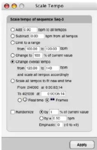
Figure 48-46: Scale Tempo.
Selecting a region to scale
The Scale Tempo command requires that you select the tempo events you wish to scale in the Conductor track before you select the command from the Region menu.
Note that the Scale Tempo command only affects tempo events that already exist in the Conductor track. If the region you select has no tempo events in it, this command will have no effect. If so, use the Change Tempo command in the Project menu (in the Conductor Track sub-menu) to generate tempo events.
There are several ways to select a region in the Conductor track. For more information, see chapter 45, "Selecting".
Add \_\_\_\_ bpm to all tempos
This option adds the number of beats per minute (bpm) you enter to each tempo event within the selected region.
Subtract \_\_\_\_ bpm from all tempos
This option subtracts the number of beats per minute (bpm) you enter from each tempo event within the selected region.
Limit to a range from \_\_\_\_ to \_\_\_\_
This option searches for tempo events above or below the specified range. When it finds one, it changes the tempo to fall within the range. For example, if the tempo range is from 200 to 300, a tempo of 351 would be changed to 300 and a tempo of 60 would be changed to 200.
Change to \_\_\_\_% of current value
This option increases or decreases each tempo event by a percent of its current value, where the current value is 100%. Use a percentage lower than 100% to slow down the tempo; use a value above 100% to raise it. Use this option when you wish to maintain the degree of change between tempos within the tempo map when you raise or lower it.
Change overall tempo from \_\_\_\_ to \_\_\_\_ and scale accordingly
This option scales the tempo events by a percentage, just like the option above it. However, it lets you specify the change in beats per minute (bpm) rather than as a percentage. For example, suppose you have a piece of music with varying tempos, but whose approximate tempo is 80 bpm. You simply wish to change it's overall tempo from around 80 bpm to around 96 bpm. Rather than figuring out what percent to type in the percentage option to achieve this change, you can use this option to type in the original approximate tempo of 80 bpm and the desired increased tempo of 96 bpm, and let Digital Performer figure out the percent increase for you. All in all, this option provides a more musical way of specifying a percent by which you wish to scale the tempos, even though it accomplishes the same thing as the "scale by percent" option.
Scale all tempos to fit new end time
This option scales all existing tempo events to increase or decrease the overall elapsed time of the selected region. The start time of the region is fixed, and the end time can be made earlier or later. Times can be expressed in real time or SMPTE frame time. Here is an example: suppose that you have created a sequence with many tempo changes, and it is around 3 minutes long. But you would like to make it 3 and a half minutes long. This option lets you select the three minute region and scale all the tempos so that it stretches out evenly to 3 1/2 minutes.
Here's another example: suppose you are locking a sequence to picture via SMPTE time code. You have composed a section of music, and you've programmed all of the tempo changes. You've got the section starting at the correct frame time, but it ends with a hit that is off by several frames. With the Scale all tempos to fit new end time option, you can select the region with the hit as the end time of the region and type in the new end time where the hit should occur. This changes the elapsed time such that the hit lands at the correct frame.
Randomize
The randomize option is a check box option that works in conjunction with the radio button option selected above.
By \_\_\_\_% of current value
This option randomizes the tempo of each selected tempo event within a range that is expressed as a percentage of the tempo value. For example, if the tempo is 100 bpm, and you enter 10 percent, the tempo will be randomized within a range between 90 to 110 bpm ( ± 10 bpm).
By ± \_\_\_\_ bpm
This option randomizes the tempo of each selected tempo event within a range of beats per minute.
Emphasis
This sub-option causes the tendency of the randomization to be higher or lower within the specified range. Thus, if you wish to randomize the tempos within a certain range, but you wish them to tend to be higher, use a positive emphasis; use a negative emphasis if you wish them to tend
to be towards the lower end of the range. A value of zero equals no emphasis, which causes the randomization to occur evenly within the range.
PACK INTO CLIPS
The Pack into Clips command places currently selected data into a clip. If the current selection spans two or more tracks, a separate clip is created in each track. When packing into a clip from a time range selection, any automation or continuous controller data present in the track is chased and preserved, such that the resulting clip sounds exactly the same as the original data in the track. Automation and controllers are not chased when packing a clip from an object selection. For more information about clips, see “What is a clip?” on page 290.
UNPACK CLIPS
Use Unpack Clips to delete a clip and place its contents at the same location within the track.
SET SEQUENCE TEMPO FROM MIDI
The Set Sequence Tempo from MIDI command analyzes the selected MIDI data and determines its tempo. This is helpful for determining the tempo of a performance with rubato sections, or one that was recorded without a click. If you are using the Conductor Track as your Tempo Control, the extracted tempo data is copied to the Conductor Track. If you are using the tempo slider as your Tempo Control, you have the option of setting the slider to the average tempo of the analyzed MIDI, or switching to Conductor mode.
If the selection of MIDI is too small for Digital Performer to properly analyze the tempo, a message will appear to let you know; in this case, try making a larger selection of MIDI data.
CAPTURE REAL-TIME MIDI EFFECTS
The Capture Real Time MIDI Effects command lets you render any real-time MIDI effects processing that is currently applied to the track via the effects inserts in the Mixing Board window. Digital Performer cuts the original data from the track, runs it through the processing currently applied to the track, and then writes the data back to the track in its processed form.
Whereas real-time effects operate on the entire track as it plays, this command allows you to apply effects to certain portions of a track.
This command is also useful when you want to tweak a real-time effect in ways that are not possible with the effect's controls. For example, you might have an arpeggiator effect applied to a track, and you might want to tweak individual note velocities of the notes it is generating. The Capture Real Time MIDI Effects command writes all of the notes permanently to the track so that you can edit them in the usual fashion.
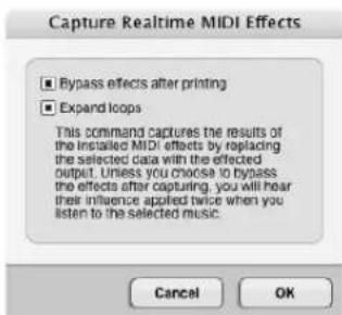
Figure 48-47: Capturing real-time MIDI effects.
Bypassing the original real-time effect after capturing
When you capture a real-time effect, you'll most often want to bypass the original real-time effect immediately afterwards. Otherwise, you'll hear the effect applied twice to your original data: once from the newly processed data generated in the track and again by the real-time effect.
For your convenience, a check box is provided in the Capture MIDI Effects dialog box as shown in Figure 48-47 to do this automatically for you.
After the effect is bypassed, you can either remove it entirely (since you may no longer need it), or leave it bypassed if you think you might want to apply it again later — or to another portion of the same track.
Expanding loops
This option, when checked, makes Digital Performer turn loops into actual data. For example, if you have a two-measure loop repeating 10 times, Digital Performer will remove the loop and paste the two measures of data ten times in a row. The result sounds the same as if the loop was still there; the only difference is that the actual data is repeated for each iteration stipulated by the original loop.
When you use this option, data that used to be overridden by the loop (data that appeared in italics in the Event List) will be removed and replaced by the expanded loop data.
If you are capturing real time MIDI effects on a track that contains loops, it is usually a good idea to check this option because if you don't, the loop will probably "override" at least some of the captured data. In other words, the captured data will appear in italics and not play because it is being overridden by the loop and its data.
An automation snapshot is the process of inserting mix automation data for multiple mix parameters in one step at a particular location — or over a specified time range. For complete details about how to use this Region menu command, see "Snapshot automation" on page 864 in chapter 71, "Mix Automation" (page 851).
SET GAP BETWEEN SOUNDBITES
The Set Gap Between Soundbites command sets the gap between each selected soundbite, and the previous soundbite, based on the time value specified in the dialog:

Figure 48-48: Set Gap Between Soundbites.
Each soundbite that is not selected is offset by the same amount, thus preserving the gaps in any non-selected bites. In other words, this command is essentially a “ripple edit” where the start time of soundbites later in the track is effected by changes to soundbites that precede them.
This command has no effect on the very first soundbite in the track. This lets you Select All and set a gap of two seconds without a gap appearing at the beginning.
Soundbites that overlap other soundbites — or that have a crossfade with another soundbite — are not treated as individual soundbites, and so no gap will be inserted between them.
This is particularly useful when preparing a sequence to be burned to CD. See “Setting the gap between CD tracks” on page 964.
INSERT MUTE AUTOMATION
The Insert Mute Automation command lets you insert mute automation data over a selected time range in any MIDI or audio track. For details, see "Insert and clear Mute Automation" on page 864.
CLEAR MUTE AUTOMATION
The Clear Mute Automation command lets you remove mute automation data in any MIDI or audio track. For details, see “Insert and clear Mute Automation” on page 864.
AUDITION SELECTION
The Audition Selection command lets you audition a selection of MIDI and/or audio data. For details, see “Playing phrases” on page 338.
CHAPTER 49 Audio Menu
OVERVIEW
The Audio menu is, in part, an extension of the Edit menu and Region menu, providing further editing operations that apply to audio data only. The Audio menu has a combination of non-destructive, destructive and constructive editing operations. (See “Non-destructive, destructive and constructive audio editing” on page 336.) In general, the non-destructive commands (such as Strip Silence) can be applied to audio that has been selected in any editor window except the Waveform Editor. Many Audio menu commands can only be applied destructively to audio selected in the Waveform Editor. The Spectral Effects command can be applied destructively in the Waveform Editor and constructively in all other edit windows, including the Soundbites window. For details about selecting soundbites in editors, see chapter 45, “Selecting” (page 547).
The Audio menu also contains soundbite management features and other audio-related operations and settings.
Dither....646
Fade 646
Delete fades 646
Freeze/Unfreeze selected tracks....646
Merge Soundbites 646
Strip Silence....646
Smooth Audio Edits....648
Spectral Effects....649
Bite volume and gain 650
Pitch and Stretch....650
Apply Plug-in 650
Audio Beats....651
Soundbite Tempo....651
Timestamps....651
Sync points 652
Duplicate Soundbite....652
Reload Soundbite 652
Replace Soundbite 655
Reveal in Finder/Show in Explorer....655
Edit in Waveform Editor 656
Use external waveform editor....656
VocAlign....656
DITHER
For an explanation of what dither is, see
"Changing bit depth with dither" on page 56 in the DP Plug-in Guide.
Digital Performer's mixing and processing engine employs 32-bit resolution. When 16-bit or 24-bit digital audio first enters Digital Performer, its bit depth (resolution) is raised to 32-bits. From then on, as the audio is mixed and processed, it remains at 32 bits until it leaves Digital Performer. The Dither command, when checked, makes Digital Performer use dither whenever it must reduce the bit depth of audio. For example, if you bounce your mix to disk as a 16-bit, 44.1kHz AIFF audio file to later burn a CD, Digital Performer converts your mix, which internally is being processed in 32 bits, to 16 bits during the bounce operation. If the Dither command is checked, dither is employed to help reduce the inherent quantization distortion that occurs when audio bit resolution is reduced.
FADE
The Fade command lets you create fades and crossfades at the boundaries of soundbites to eliminate undesirable artifacts. For complete details, see “Fades and Crossfades” on page 657.
DELETE FADES
See "Deleting fades" on page 663.
FREEZE/UNFREEZE SELECTED TRACKS
The Freeze Selected Tracks command can be thought of as a “mini”, temporary bounce: it creates a new audio track, with the same output as the original track, that contains a record pass of the entire original track, complete with all real-time effects rendered to the track. You can then disable the original track, and its real-time effects plug-ins or virtual instruments, to conserve computer power. For details, see “Freezing tracks” on page 152.
MERGE SOUNDBITES
Use Merge Soundbites to quickly create a single, new soundbite out of several adjacent soundbites. To do so, select the adjacent soundbites and choose Merge Soundbites from the Audio menu. This operation creates a new audio file, sort of like a “mini-bounce”. But it does not include any volume, pan or other automation data. It is meant for joining audio regions on a small, local scale.
If you use the Merge Soundbites command when there is a time range selection that extends beyond the selected soundbites, the resulting soundbite extends to the beginning and end of the selection.
STRIP SILENCE
Strip Silence breaks up a soundbite into several smaller soundbites by removing all of the portions that consist of silence.
Before:

After:

Figure 49-1: Strip Silence.
For example, you can use Strip Silence to remove the silence between words to separate them.
To use Strip Silence:
1 Click the soundbite in the Sequence Editor or Event List to select it.
2 Choose Strip Silence from the Audio menu.
A dialog box appears asking for several parameters. See the discussion below for more information.
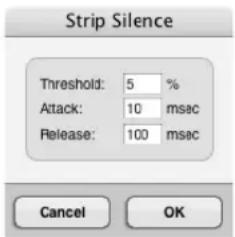
Figure 49-2: The Strip Silence dialog.
3 Set the options accordingly and Click OK.
4 Play back the new soundbites to check for clicks, pops, or cutoffs.
If the parameters you chose do not produce soundbite regions that are satisfactory, choose Undo from the Edit menu and try again with different parameters.
5 When you get soundbite regions you are satisfied with, Option/Alt-click their names to rename them, if desired.
Setting the Strip Silence options
When you remove silence in a soundbite, Digital Performer needs a precise definition of silence from you, since there is always some noise in a recorded audio signal. The three options in the Strip Silence dialog box define silence. Together, they act just like a noise gate. They define a volume threshold, an Attack period, and a Release period.
Threshold
The Threshold is a cut off point for the (amplitude) level of the audio. If audio falls below the threshold, it will be cut. If it rises above the threshold, it won't be cut.
The Threshold is expressed in percent of amplitude; values range from 1 to 100%. What value you should use depends on the nature of the audio and the signal to noise ratio. The rule of thumb is to try to set it as low as possible without generating unwanted soundbites (that are merely “noisy silence”) or extensions at either end of soundbites. Using a low setting results in less clicks, pops, or clipping at the beginnings and ends of the soundbites created. But if you set the threshold too low, then hardly any audio will be removed, and you may still have unwanted low portions of the signal.
For “clean” audio with a high signal to noise ratio, use a Threshold value below 5%. You may be able to go as low as 1%, which will reduce a possible clipping effect at the beginning or end of each new soundbite and still produce individual soundbites that do not have an excessive amount of near silence at either end. With more noisy audio, you may have to select a higher Threshold to avoid creating lots of short, unnecessary soundbites.
Attack
The Attack is the minimum amount of time in milliseconds that audio must remain above the Threshold in order not to be cut. If the audio contains percussive attacks, such as drum sounds, you can set this fairly low (less than 10 milliseconds) to obtain a clean attack on the resulting soundbites. If the audio contains longer, sloping attacks, or irregular attacks, you might need to set this higher to avoid a clipped effect at the beginning of the soundbite.
Release
The Release is the period of time in milliseconds in which the audio must remain below the threshold in order to be cut. If the audio stays below the threshold for as long as the duration, it will be cut. If it rises above the threshold before the duration
has passed, it will not be cut. Try values around 100 milliseconds. Set this value higher if the soundbites sound clipped at the end.
SMOOTH AUDIO EDITS
Audio edits often produce gaps between soundbites. This is especially true when editing dialog, or splitting soundbites into small slices using the New Soundbites from Beats command (Audio menu > Audio Beats). Gaps of silence between soundbites can be audible and usually sound unnatural. The Smooth Audio Edits feature fills these gaps with “room tone” to mask them.
Room tone
Room tone is Digital Performer's term for a small portion of ambient sound from the original audio file (or possibly another audio file). Digital Performer can automatically search the parent audio file for a small portion of the waveform that consists of noise floor: consistent, low-level background noise that can fill silence between soundbites and crossfade seamlessly with the beginning and end of each soundbite. Or you can manually specify a room tone audio file. In either case, Digital Performer then fills the gaps between soundbites with the room tone "silence", which matches the noise floor in the soundbites enough to provide a smooth, unnoticeable transition from one soundbite to the next.
At times, the gap to be filled may sit between soundbites that are from different recording sessions with completely different noise floor characteristics. If so, Digital Performer still tries to make the transition as smooth as possible. To do so, it finds noise from each parent audio file and creates a new soundbite to fill the gap that consists of a crossfade blend from one file's noise to the other file's noise.

Figure 49-4: Smooth Audio Edits.
To apply Smooth Audio Edits, make a time range selection over the area that contains the gaps between soundbites that you wish to fill. Then choose Audio menu> Smooth Audio Edits. A window appears (Figure 49-4) with the several options discussed below.
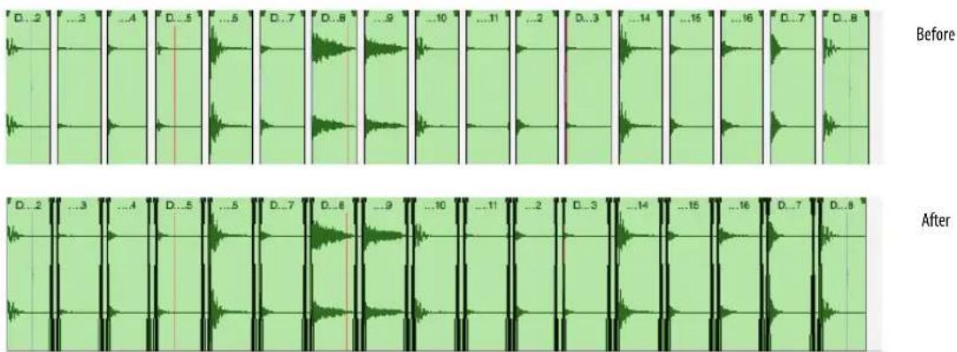
Figure 49-3: The effect of applying Smooth Audio Edits.
Specifying what gaps to fill
To fill all gaps of silence, choose Replace Silence with Room Tone.
To specify the size of the gaps to be filled, choose Only Fill Gaps smaller than _ with Room Tone.
If you wish to automatically generate crossfades between soundbites and the newly created room tone soundbites between them, check the Crossfade Edits check box.
Specifying how to fill gaps
The Find Room Tone By options let you decide how the gaps will be filled. There are essentially two basic techniques for doing so: edge edit (trim) the edges of the existing soundbites to “uncover” room tone that is just past the edge of the soundbite, or insert new room tone soundbites. Or, you can do both by trimming soundbites as far as possible until they run out of audio (or run into other portions of the waveform that rise above the noise floor), and then inserting room tone soundbites to fill any remaining gaps. This last approach usually produces the most natural sounding and complete results. To employ it, choose Edge Editing then Inserting Audio From File. If you wish to edge edit only or insert room tone only, choose either Edge Editing Only or Inserting Room Tone Audio From File.
Specifying how room tone is generated
The final options in the Smooth Audio Edits dialog let you choose how room tone is generated. If you want Digital Performer to automatically generate room tone by searching for it near the soundbites in their parent audio file, choose Creating Room Tone from Adjacent Audio. If you would like to create your own room tone audio file and use that instead, choose Use Room Tone Soundbite and click the Choose button to specify the file.
SMOOTH AUDIO EDITS AGAIN
If you wish to apply the same smoothing settings as were just used, hold down the Command/Ctrl key and choose Audio menu> Smooth Audio Edits Again. Doing so applies the same settings last used by this command to the current selection, as a convenient shortcut.
SPECTRAL EFFECTS
The Spectral Effects command allows you to apply Digital Performer's formant-corrected pitch-shifting, time stretching and "gender-bending" to monophonic digital audio. For details, see chapter 80, "Spectral Effects" (page 931).
BITE VOLUME AND GAIN
There is a soundbite attribute, accessed in the Sound File Information window (“Sound File Information” on page 365) and in the Sequence Editor (“Bite Gain” on page 393), called Bite Gain. It non-destructively raises or attenuates the overall volume of the soundbite. The range is from -140 to +80 dB. There is an additional soundbite attribute that temporarily bypasses both soundbite gain and soundbite volume automation. When bypass is engaged, the soundbite plays at its original volume. The commands in the Bite Volume and Gain sub-menu control these settings for individual soundbites. To use them, select a soundbite (either in the Sequence Editor or in the Waveform Editor) and choose the desired command below:
Soundbite volume submenu item What it does
| Set Bite Gain Sets the selected soundbite's gain to the value entered in the dialog. |
| Clear Bite Gain Sets the selected soundbite's gain to 0.0dB |
| Toggle Bite Volume Bypass Toggles the gain/volume bypass setting for the selected soundbites |
| Adjust Bite Volume +0.5dB Adds a half a dB to any soundbite volume within the current selection. |
| Adjust Bite Volume -0.5dB Subtracts a half a dB from any soundbite volume within the current selection. |
Clear Bite Volume Clears the selected range in the soundbite volume curve.
For breakpoint editing of soundbite volume automation in the Sequence Editor, see “Soundbite volume automation” on page 407. You can also edit soundbite volume automation in the Waveform Editor. See “The Bite Volume layer” on page 542.
PITCH AND STRETCH
The commands in the Pitch and Stretch sub-menu let you control Digital Performer's real-time pitch automation data. For complete information, see chapter 81, "Transposing Audio" (page 935). Here is a brief summary of the commands in this sub-menu:
Pitch mode command What it does
| Clear Pitch Returns a pitch segment to its original pitch. See “Pitch curve control points” on page 939. | |
| Clear Pitch Control Points | Removes any control points in the currently selected portion of a pitch curve. See “Pitch curve control points” on page 939. |
| Quantize Pitch Centers any currently selected pitch segments, so that they are tuned exactly to their relative root pitch (to fix any notes that are a little sharp or flat). See “Quantizing pitch” on page 943. | |
| Scale Expression | Accentuates or flattens the currently selected pitch curve. See “Scaling the pitch curve” on page 939. |
| Adjust Pitch Segmentation | Raises or lowers the number of pitch segments used to manipulate audio pitch. See “Adjusting pitch segmentation” on page 941. |
| Set Track Pitch Mode | Sets the default pitch mode for any audio material newly recorded into that track. It does NOT affect existing soundbites already in the track, or soundbites dragged into the track. See “Setting the pitch mode” on page 940. |
| Set Pitch Mode for Selected Bites | Sets the pitch mode and modifies the pitch segments accordingly for the currently selected audio in the Soundbites window or in any tracks. See “Setting the pitch mode” on page 940. |
Set Pitch Mode for Track Applies the pitch mode to both the track and Selected Bites and any currently selected soundbites as described above in one operation. See "Setting the pitch mode" on page 940.
APPLY PLUG-IN
The Apply Plug-in sub-menu holds non-real-time versions of your MAS, VST and AU plug-ins, allowing you to apply them constructively as region operations on audio selected in any window. For more information, see “File-based plug-in processing” on page 898.
AUDIO BEATS
The Audio Beats sub-menu lets you manage Digital Performer's extensive audio beat detection features.
Audio beats menu item What it does
| Find Beats... Triggers Beat Detection on selected audio files in the Sequence Editor, Tracks window or Waveform Editor with the user-set detector sensitivity setting. See “Find Beats” on page 685. | |
| Clear Beats Removes all the beats from the selected audio files. | |
| Disable Beats under Strength Threshold... | Controls how many beats are enabled or disabled in a soundbite based on their velocity threshold. See “Disable Beats under Strength Threshold” on page 687. |
| New Soundbites From Beats... | Lets you split up a soundbite into pieces at beat boundaries. See “New Soundbites from Beats” on page 687. |
| Copy Beats... Copies beats from one track to another. See “Copy Beats” on page 690. | |
Copy Beats as MIDI Copies beats into the clipboard as MIDI notes with velocities that match the beat strength. See "Copy Beats as MIDI" on page 686.
SOUNDBITE TEMPO
Digital Performer provides many advanced features for managing audio tempos. For complete information about the soundbite tempo commands in the Audio menu, see “Tempos and Audio” on page 673 and chapter 53, “Audio Beats and Tempo Detection” (page 681).
TIMESTAMP
A timestamp is the SMPTE timecode location at which a soundbite starts and ends. Digital Performer provides a host of features for creating, importing, displaying, modifying and using timestamps.
Original Timestamp
There are four ways in Digital Performer to create a soundbite with an original timestamp:
■ Record it
■ Bounce it
■ Export it to a hard disk track from POLAR
■ Create it with the Merge Soundbites command
You can also import soundbites with timestamps.
User Timestamp
A user timestamp can be applied to a soundbite at any time with the Set User Timestamp from Sequence command in the Audio menu.
Timestamps and editing
Timestamps are preserved when you perform non-destructive soundbite edits. For example, if you trim the beginning of a soundbite, the timestamp changes to reflect the new location of the left edge of the soundbite. If you split a soundbite, each resulting soundbite has a timestamp consistent with the original soundbite's timestamp.
Moving soundbites to their original or user timestamp
Regardless of their current location, you can always move soundbites to their original or user timestamp location by selecting them and choosing the Move to Original Timestamp or Move to User Timestamp command from the Timestamps sub-menu in the Audio menu.
Setting a user timestamp
To apply a user timestamp to one or more soundbites, place the soundbites at the desired location in the sequence, select them, and then choose Timestamps > Set User Timestamp from Sequence in the Audio menu.
If you have the same soundbite positioned at different locations in your project, and you then apply a user timestamp, Digital Performer notifies you that the soundbite is being used at more than one location. It then gives you the option of duplicating the soundbite so that each occurrence can be given the correct timestamp.
Editing timestamps
You can view and change timestamps in the Sound File Information and Event Information windows. For details, see “Sound File Information” on page 365 and “Event Information” on page 359.
Displaying timestamps
You can view a soundbite's original and user timestamp in the Soundbites window, if desired. See “The Soundbite list” on page 43.
You may also view the original or user timestamp on your soundbites in the Sequence Editor. See "Show times" on page 398
Searching by timestamp
Digital Performer's powerful search feature lets you locate soundbites by their timestamps, as demonstrated below.
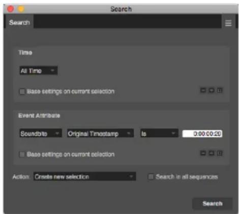
Figure 49-5: Searching by original or user timestamp.
Exchanging timestamped audio with other applications
Digital Performer stores both its user timestamp and the original timestamp with the region data in the parent audio file itself. Therefore, you can freely transfer timestamped audio files between Digital Performer and other applications that can read this timestamp data directly from the audio file, such as Pro Tools.
SYNC POINTS
A sync point can be placed inside a soundbite as positional reference point for the soundbite instead of its beginning (left edge). See “Sync points” on page 399.
DUPLICATE SOUNDBITE
The Duplicate Soundbite command in the Audio menu creates an entirely new soundbite based on the currently selected soundbite. The new soundbite is given a different name from the original by adding a number extension to the end of the original name. For example, if you duplicate a soundbite with the name Snare Hit, Duplicate creates an identical soundbite with the name Snare Hit.2. The important thing to realize here is that you now have two separate soundbites that are not connected to each other. As a result, you can freely modify Snare Hit.2 (trim its edge, for example) without affecting the original soundbite, Snare Hit.
Duplicating is different from copying a soundbite, which produces a “clone” of the original that is still connected to it. If you modify a copied soundbite, the original is modified, too (and vice versa).
The Duplicate Soundbite command does not duplicate the actual audio data; it duplicates pointers to the audio data. Therefore, destructive editing that you perform on the duplicate soundbite will affect the original soundbite. So be careful when editing duplicate soundbites with the Waveform Editor.
RELOAD SOUNDBITE
When a soundbite is created, Digital Performer adds a corresponding region in the audio file with the same name as the soundbite. Digital Performer does this so that other applications can access and use the regions. Most importantly, it prevents the region from being deleted when using the
Compact command. (The Compact command never deletes audio data that falls within a region in the audio file's region list.)
Use Reload Soundbite any time that you have made changes to a region in an audio file using software other than Digital Performer and wish those changes to be reflected in the region's corresponding soundbite in Digital Performer.
For example, let's say that you have changed a region's boundaries in an audio file using a third-party waveform editor such as BIAS Peak, and you then switch back into Digital Performer. But now a discrepancy exists between the region in the audio file and the soundbite in the Digital Performer file: the soundbite still consists of the original region, not the modified one. To make the soundbite match the region again, use the Reload Soundbite command.
To reload a soundbite, select the soundbite by highlighting them in the Soundbites window, Event List, or Sequence Editor. (The Reload Soundbite command operates on only one soundbite at a time. If you select more than one in the Soundbites window, it replaces the highest one in the list. If you select more than one soundbite in the Event List or Sequence Editor, it replaces only the earliest one.) Choose Reload Soundbite from the Audio menu. Digital Performer searches in the parent audio file for a region that matches the name of the soundbite and loads the parameters for the region into the soundbite. Reload Soundbite affects all instances of a soundbite in a Digital Performer file.
Reloading after destructive editing in an audio file
As another example, let's say that you have created several soundbites in Digital Performer.
If you open the audio file with a third-party waveform editor and cut a region of audio data at the beginning, all of the regions after the cut are shifted earlier, as shown in Figure 49-6 on page 654. Digital Performer, which may not even be running at the time, has no indication that anything has changed in the audio file.
The soundbites in Digital Performer no longer correspond correctly with the original regions of audio data, which have shifted earlier in the audio file due to the removed data. In fact, as you can see in Figure 49-6, Digital Performer is pointing to Soundbite.3 in a portion of the audio file that no longer even exists!
By using the Reload Soundbite command on the soundbites, you can properly re-align the soundbites in Digital Performer with their original regions of audio data:
To reload a soundbite:
1 Select the soundbite you wish to reload.
You can do so by highlighting it in the Soundbites window, Event List, or Sequence Editor.
2 Choose Reload Soundbite from the Audio menu.
Digital Performer searches in the parent audio file for a region that matches the name of the soundbite and loads the parameters for the region into the soundbite.
The Reload Soundbite command can be used any time that you need to refresh the boundaries of a soundbite.
In general, always use Reload Soundbite after modifying an audio file with other software besides Digital Performer.
Reload Soundbite affects all instances of a soundbite in a Digital Performer file. In other words, reloading affects the soundbite and all “clones” of that soundbite wherever they may exist in audio tracks.
You'll notice that Reload Soundbite isn't really going to be used much if you don't use any other programs besides Digital Performer to work with the audio file. However, any time that you edit regions or audio data in an audio file, think about what impact the editing has on any Digital Performer files that contain soundbites from that audio file.
Reloading all soundbites in an audio file at one time
Often, you'll have several — and usually many — soundbites that originated the same audio file, and you'll need to reload all of them. Certainly a tedious task if you had to do so one at a time. But there is a shortcut for reloading all of them at once:
1 Command-double-click the name of the parent audio file next to one of the soundbites in the Soundbites window.

flowchart
graph TD
A["Audio file: Soundbite.1"] --> B["Audio data that will be cut in BIAS Peak"]
C["Digital Performer soundbites as regions in an audio file"] --> D["Digital Performer soundbite pointers remain the same after audio has been cut with other audio software."]
E["Audio file: Soundbite.1"] --> F["The Reload Soundbite command realigns soundbite pointers with their original regions of audio data."]
G["Audio file: Soundbite.1"] --> H["The Reload Soundbite commands realigns soundbite pointers with their original regions of audio data."]
Figure 49-6: Using Reload after destructively editing an audio file with another program.
It doesn't matter which soundbite you choose, as long as its from the parent audio file you need to reload from.
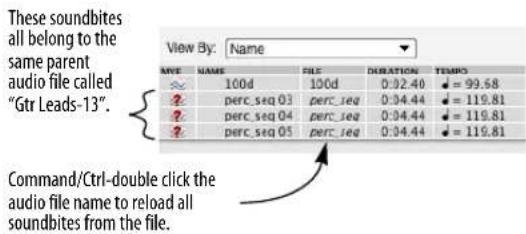
2 In the dialog box that appears, locate and select the parent audio file.
If you are doing this procedure after having moved the entire project from one hard disk location to another, be sure to select the newly copied version of the audio file — not the original.
That's it. Digital Performer automatically reloads all of the soundbites in the file.
If reloading fails
The Reload Soundbite command fails if Digital Performer cannot find a region with the same name as the soundbite in its parent audio file. Or, it may not be able to find the parent audio file. If so, Digital Performer warns you that this is the case and asks you to select another region to replace the soundbite. For information about replacing soundbites, refer to the next section.
REPLACE SOUNDBITE
The Replace Soundbite command is similar to Reload Soundbite but gives you more flexibility. It allows you to replace a soundbite with any audio file region—even an entirely different region from another audio file. In addition to updating the soundbite's start and end pointers, Replace Soundbite also updates the name if the soundbite is being replaced by a region with a different name. Just like Reload Soundbite, Replace Soundbite replaces all instances of a soundbite in a Digital Performer file. Here's an example. Let's say that you recorded a vocal soundbite, named it Yeah!, and are using it as an effect in a mix. You have placed it fifteen or twenty times throughout the mix. During the course of the session, you decide that you would like to replace all the Yeah!'s with a different soundbite that you recorded and named Hey! Replace Soundbite makes substitutions like this easy.
To replace a soundbite:
1 Select the soundbite that you wish to replace.
The Replace Soundbite command operates on only one soundbite at a time. If you select more than one in the Soundbites window, it replaces the highest one in the list. If you select more than one soundbite in the Event List or Sequence Editor, it replaces only the earliest one.
2 Choose Replace Soundbite from the Audio menu.
The open audio file dialog box appears.
3 Select the audio file and region you want to replace the soundbite with.
After you click the Done button, the new region takes the place of the old region. Likewise, all instances ("clones") of the old region in all the tracks are replaced as well.
REVEAL IN FINDER/SHOW IN EXPLORER
The Reveal In Finder/Show in Explorer command shows you the location (in the macOS Finder or Windows Explorer) of the parent audio file for the currently selected soundbite or clippings. By default, the keyboard shortcut for this command is Option/Alt-R.
EDIT IN WAVEFORM EDITOR
Edit in Waveform Editor switches you directly into Digital Performer's Waveform Editor window, with Pencil tool editing of the waveform and other tasks. For complete information, see chapter 44, "Waveform Editor" (page 525).
USE EXTERNAL WAVEFORM EDITOR
The Use External Waveform Editor command is a checkable menu item in the Audio menu. When you first choose this command, it lets you choose a third-party waveform editor, such as BIAS Peak ™ , as your preferred waveform editor (instead of Digital Performer's own built-in Waveform Editor). In addition, the menu item becomes checked to indicate that it has remembered your preferred external editor. Accordingly, whenever you invoke the Edit in Waveform Editor command, Digital Performer automatically launches the third-party waveform editor and opens the audio file with the region selected for editing.
When the Use External Waveform Editor command is unchecked, Digital Performer's Waveform Editor opens instead.
VOCALIGN
VocALign is an audio alignment tool from SynchroArts that automatically synchronizes two audio signals at the touch of a button. For complete details, see chapter 83, "VocAlign" (page 949).
CHAPTER 50 Fades and Crossfades
OVERVIEW
Digital Performer allows you to apply fades and crossfades to the edges of soundbites.
What is a crossfade?....657
Creating a single fade or crossfade....658
Types of crossfades....660
Fade curves....661
How fades are generated....662
Fades are anchored to their splice....662
Applying multiple fades in one operation....663
Reapplying the last fade settings ....663
Deleting fades....663
Editing existing fades....664
Fades that cannot be fully computed ....664
Trimming soundbites that have a fade or crossfade . . .664
Clipping when crossfades are calculated .....664
WHAT IS A CROSSFADE?
A crossfade occurs at the boundary — what we'll call the splice point — between two soundbites. It fades out the volume of the first soundbite while fading in the volume of the second. A crossfade's main purpose is to produce a smooth transition between the soundbites, preventing clicks and pops and other undesirable artifacts that can sometimes occur. Crossfades are general in nature, however, and they can also be used for volume effects and other purposes.
A fade is similar to a cross fade, except that it occurs at the start or end of a single soundbite, and it fades between the soundbite and silence.
Fades and crossfades do not modify the original audio in any way, and you can remove the fade or crossfade at any time.
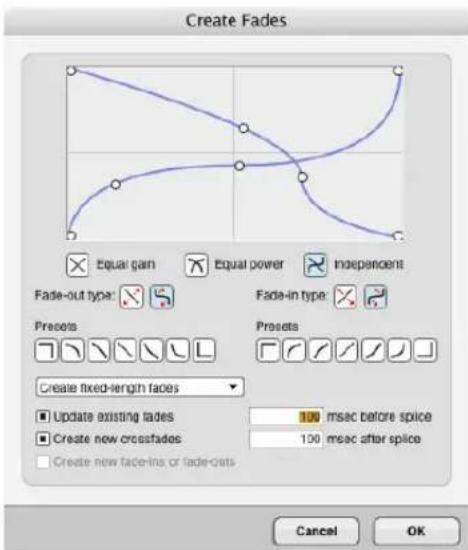
Figure 50-1: To create a fade or crossfade, select one or more soundbite boundaries and choose Fade from the Audio menu.
CREATING A SINGLE FADE OR CROSSFADE
There are two ways to create a fade or crossfade:
■ Drag the fade/crossfade handles on a soundbite
■ Make a selection and apply a fade with the Fade command (Audio menu).
Creating a fade/crossfade with fade handles
Fades and crossfades can be applied directly to soundbites by pulling fade or crossfade handles directly on the soundbites, as shown below in Figure 50-2:

Figure 50-2: Position the cursor over a fade or crossfade handle until you see the fade/crossfade cursor shown above. Then just pull out a fade of the desired length. Double-click the fade or crossfade to edit its shape further.
To create a fade at the boundary of two soundbites that are touching, hold down the Command/Ctrl key while dragging one handle or the other:

Figure 50-3: Hold down the Command/Ctrl key to create a fade (instead of a crossfade) where two soundbites touch.
Fades and crossfades are inserted with the shape most recently specified in the Fade dialog (Audio menu).
By default, fades and crossfades are inserted and edited symmetrically. To shorten or lengthen just one side of a crossfade while pinning the other side where it is, hold down the Option/Alt key while dragging the fade handle as shown below:

Figure 50-4: Option drag to move just one side of the fade. The other handle remains pinned to its original location.
To edit multiple fades together in one operation, select the soundbites that contain the fades, and then grab the fade handle of one of the selected soundbites:
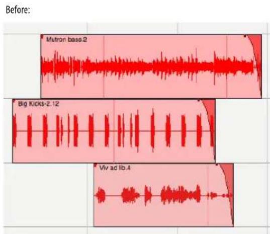

Figure 50-5: Editing multiple fades in one operation.
For example, if you needed to make all fades in a track a little longer, you can select all soundbites and then grab one fade to change them all.
Applying a fade/crossfade to a selection
To apply a single fade or cross fade to a selection:
1 In the Sequence Editor, make a selection over a splice point (the soundbite boundary that defines the fade or crossfade you wish to create). You can use your selection to define the length of the crossfade, or you can create a fixed-length fade that is different from your selection.

Figure 50-6: Making a selection over a soundbite boundary to apply a fade.
2 Choose Fade from the Audio menu to open the Create Fades dialog, as shown in Figure 50-1.
3 Set the fade-out and fade-in curves as desired. These curves are explained later in the chapter.
4 To create a fade over the exact length of your original selection, choose the Fade selected time ranges option from the menu at the bottom of the dialog. To create a fade of a specific length, choose Create fixed-length fades and then enter the desired length for the fade (in milliseconds) in the before splice and after splice text boxes.
5 Click OK to apply the fade.
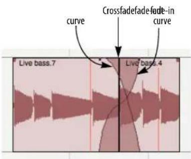
Figure 50-7: A crossfade.
TYPES OF CROSSFADES
When you apply a crossfade, the selection you make relative to the splice point determines the type of crossfade. If you make a selection with the splice point somewhere in the middle, you will create a standard, centered crossfade as shown below in Figure 50-8.
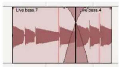
Figure 50-8: A centered crossfade.
If you make a selection to the left of the splice point, you create a pre-crossfade before the splice point as shown below in Figure 50-9. This will let you maintain the volume of the beginning of Soundbite 2 without fading across it. This is especially useful if there is a percussive downbeat at the beginning of Soundbite 2 that you want to preserve.

Figure 50-9: A pre-crossfade.
If you make a selection to the right of the splice point, you create a post-crossfade as shown below. This is useful if you want to maintain the volume of Soundbite 1 right up to the splice point.

Figure 50-10: A post-crossfade.
Crossfades use material beyond the splice
All three types of crossfade discussed in the previous section use “hidden” material in each region beyond the splice point. In the centered crossfade shown below, the fade-out starts in ‘Bass riff 1’ and extends into the beginning of ‘Bass riff 2’; the portion of the fade-out to the right of the splice point is actually calculated from material in Bass riff’s parent audio file — material that is currently not visible.

Figure 50-11: The area beyond 'Bass riff 1' in its parent audio file is used to calculate the fade-out curve of the crossfade. The same is also true for the area preceding 'Bass riff 2' in its parent audio file.
If there isn't enough additional material in the parent audio file for the fade-out (or fade-in) calculation, the fade will drop to zero at that point.
Fades mix with silence
Fades, on the other hand, do not use material beyond the edges of the soundbite from the parent audio file. Instead, they mix with silence to create a smooth transition to (or from) zero volume.
Fade types
The fade dialog box offers three types of crossfades and two types of fades:

Equal gain
Equal gain crossfades are recommended for material that is phase coherent or nearly phase-coherent, as in crossfades between soundbites from the same audio source material (the same instrument, for example). Equal gain crossfades help avoid clipping that can occur when using equal power crossfades (described below). Equal gain fades are available for both fades and crossfades.

Equal power
Equal power crossfades are recommended for material that is not phase coherent, such as completely different musical instruments. Equal power crossfades help you to avoid the volume drop that can sometimes occur with equal gain crossfades. Equal gain fades are available for both fades and crossfades.

Independent
Independent crossfades are recommended for special circumstances in which you cannot achieve the desired results with the equal gain or equal power curves — or when you specifically need to create entirely different fade-out and fadein curves. This option only applies to crossfades; it is not available for fades (since a fade consists of only one curve).
FADE CURVES
For all of the fade types discussed in the previous section, you can choose between a standard fade curve or an S-shaped curve. If you are using an equal power or equal gain crossfade, both the fade-in and fade-out curve must be the same curve type. (The curve buttons in the window enforce this for you.) However, if you are using independent curves, you can choose a different curve type for the fade-in and fade-out.
Regardless of which fade type you create, you are given handles on the curves in the diagram to further adjust the curve. The standard fade curve offers a single handle; it creates a smooth, continuous general-purpose fade. The one exception to this is when you are using independent curves, in which the standard curve also gives you two end points that let you modify where the curve starts and ends.

Figure 50-12: Here is an example of an equal gain crossfade with a standard curve.
S-shaped curves give you several handles, including one at the crossover point where it inverts its shape. S-curves are particularly useful for material that is hard to crossfade with a standard curve.
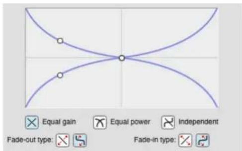
Figure 50-13: Here is the same equal gain crossfade shown in Figure 50-12 with an S-shaped curve instead of a standard curve.
When you choose independent S-shaped curves, you can get as elaborate as you need.
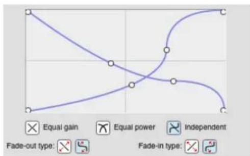
Figure 50-14: Here is a crossfade with independent S-shaped curves.
Fade curve presets
On each side of the Fades dialog, below the fade-out and fade-in sections, there is a row of buttons that provides you with several useful fade curve presets. These presets are commonly useful curves provided as a convenience to you. They are by no means “magical” in any way. These curves will cover most of the situations you encounter. You can also use them as a starting point and then further tweak them with the handles in the curve diagram.

For the most part, the icons on the buttons give you a pretty good idea of the shape of the curve and the effect it will have on your audio. The "square corner" presets are notable because the
keep the volume of the fade-in or fade-out constant — either full volume or zero volume — for the entire length of the fade.
HOW FADES ARE GENERATED
When you make a fade (or crossfade), Digital Performer computes the fade on-the-fly — no files are created on disk. Fades are applied non-destructively, just as with volume automation or real-time effect inserts.
FADES ARE ANCHORED TO THEIR SPLICE
In general, fades and crossfades are preserved during editing operations such as dragging, shifting, compacting or setting the soundbite start time. For example, if you trim the edge of a soundbite, and it has a fade on it, the fade will remain after the trim operation. The same applies to deleting the end of a soundbite with a fade. In either case, if the audio data within the range of the fade or crossfade changes, it will be recomputed automatically.
There are a few situations in which crossfades cannot be preserved, due to their nature.
Crossfades are defined by the splice to which they were applied. If the splice point changes, the fade may no longer be valid because the original arrangement of audio data from which the fade was computed no longer exists. As a result, crossfades always remain anchored to the soundbite edge (or boundary between two soundbites) to which they were originally applied. They cannot be moved independently of their splice point — although they can move with their splice point (as long as it doesn't change in the process). For example, if you move one of the two soundbites that define a crossfade, the crossfade will disappear. If you move them together, the crossfade will move with them.
APPLYING MULTIPLE FADES IN ONE OPERATION
Often, you'll need to apply several — and possibly many — crossfades at one time. Rather than having to painstakingly apply them one at a time, Digital Performer allows you to apply as many fades as you want in one operation. One way to do this is to use the Shift key to select several splice points at one time before entering the Fades dialog. You can then apply the same fade to all of them, using your selections to define the length of each fade. Or you can apply fixed-length fades.
Another way to apply multiple fades at one time is to make one large selection that contains any number of splice points and then apply fixed-length fades to all of them in one operation. This technique is especially useful when you've made many detailed edits — perhaps dozens or even hundreds — and you need to apply crossfades to all of them.
To apply fixed-length fades and/or crossfades to many splice points in one operation:
1 In the Sequence Editor, select the region that contains the splice points you would like to fade and/or crossfade. For example, if you want to apply fades and crossfades to all soundbite boundaries in the entire sequence, display all tracks in the Sequence Editor and Select All.
2 Choose Fade from the Audio menu to open the Fades dialog.
3 Choose Create fixed-length fades from the menu at the bottom of the window.
4 If the region you selected contains existing fades, and you would like to replace them with new fades, check the Update existing fades option. If you want to preserve existing fades, leave it unchecked.
5 If you would like to apply crossfades to all eligible splice points (ones that consist of boundaries between two touching soundbites), check the Create new crossfades option. If you don't want to create any crossfades where soundbites touch, leave it unchecked.
6 If you would like to apply fades to all soundbite edges (e.g. edges that are not touching another soundbite), check the Create new fade-ins or fade-outs option. If not, leave it unchecked.
7 Enter the length of the fade by entering times in the before splice and after splice value boxes provided. Values are in milliseconds (100 = one tenth of a second).
8 Click OK to generate the fades.
When you click OK, Digital Performer's applies the fades. Use the Background Processing window to monitor its progress. You can, of course, proceed with other work when the fades are being processed, if you like. Fades that are not calculated yet are displayed in gray; fades that are done appear in the same color as the soundbite.
REAPPLYING THE LAST FADE SETTINGS
To apply another fade using the same settings you last used, hold down the Option/Alt key while choosing Fade from the audio menu.
DELETING FADES
To delete a single fade, click it and choose Delete Fades from the Audio menu.
To delete all fades within a region, select the region and choose Delete Fades from the Audio menu.
To delete all fades in the entire sequence, use Select All in the Tracks window (or the Sequence Editor with all tracks showing) and choose Delete Fades from the Audio menu.
EDITING EXISTING FADES
To modify an existing fade, double-click it.
To modify several existing fades at one time, select them and choose Fade from the Audio menu.
In either case, after you've made the changes you would like in the Fades dialog, make sure that the Update existing fades option is checked before clicking OK.
FADES THAT CANNOT BE FULLY COMPUTED
If Digital Performer computes a fade or crossfade and the level of the mixed audio in it exceeds unity gain (0 dB), the fade appears bright red to alert you to the fact that it is clipping.
If, for some reason, a fade or crossfade doesn't have enough audio for Digital Performer to compute the complete fade, it appears bright blue. For example, you might draw a crossfade that is two seconds long, but one of the soundbites involved may not have a full extra second of audio in the parent audio file beyond the edge of the soundbite. In this case, the crossfade appears bright blue to indicate that it cannot be fully computed.
TRIMMING SOUNDBITES THAT HAVE A FADE OR CROSSFADE
If a soundbite edge has a fade or crossfade on it, you have to delete the crossfade in order to change it. This makes sense because as soon as you change it, the crossfade is no longer valid anyway (since the splice point has changed). You can reapply the crossfade after you modify the soundbite edge.
CLIPPING WHEN CROSSFADES ARE CALCULATED
If clipping occurs when Digital Performer calculates a crossfade, the crossfade is drawn in red instead of the soundbite's color. In this case, you will probably want to re-apply the crossfade,
adjusting the curves. Try using the equal gain curves (since it is impossible for clipping to occur when using equal gain).
CHAPTER 51 Takes and Comping
OVERVIEW
A take stores the contents of the track. Each track can have an unlimited number of different takes. If you want to keep what is already in a track, but you want to try an alternative version of it (either recorded from scratch or based on the current take), choose New Take or Duplicate Take from the Take menu. The original data is preserved in its own take, which you can always return to by choosing it by name from the Take menu.
Takes are great for cycle-recording. If you'd like to try recording again the next time through the loop, just choose New Take from the menu. Your previous take is saved, and a new, empty take is ready to be recorded into. After you are done, you can either choose the best take, or quickly build a final composite track made of the best parts of several takes using the Comp tool.
Takes can be used with all track types. When used with audio tracks in the Sequence Editor, you can use Digital Performer's powerful comping features to quickly create a comp take from multiple takes.
Take menu 665
Indication of multiple takes....666
Comp takes....666
Comp tool....668
Takes and key commands ....670
Conductor track takes ....671
Takes interact with multiple mixdowns....671
TAKE MENU
The Take menu (Figure 51-1), found in the Tracks List take column and the Sequence Editor info panel as shown below, has several commands to help you manage takes.
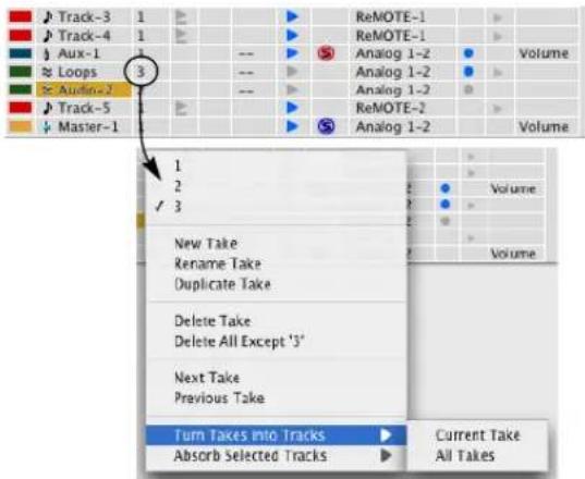

Figure 51-1: The Take menu.
New Take
New Take (Figure 51-1) creates a new, empty take for the track.
Rename Take
Rename Take (Figure 51-1) lets you rename the current take. The current take is the one with the check mark next to it in the top portion of the menu.
Duplicate Take
Duplicate Take (Figure 51-1) creates an exact duplicate of the current take, including all of the data in the track. The current take is the one with the check mark next to it in the top portion of the menu.
Delete Take
Delete Take (Figure 51-1) gets rid of the current take.
Delete all except 'current take'
Delete all except 'current take' (Figure 51-1) gets rid of all takes except the current take.
Turn Takes into Tracks
Turn Takes into Tracks (Figure 51-1) removes takes from the track and turns them into separate tracks. The Current Take sub-menu option is only available when there are two or more takes, and it operates on the current take. The All Takes option removes each take and turns it into a separate track containing a single take.
Absorb Selected Tracks
Absorb Selected Tracks (Figure 51-1) lets you collect takes from other tracks into the track from which you choose this command. To do so, select the tracks you wish to “absorb”, then choose this command from the take menu of the track you wish to absorb them into. The selected tracks are deleted. The Current Takes sub-menu option only absorbs the current take of the selected tracks, whereas the All Takes option absorbs all takes from the selected tracks.
For audio tracks in the Sequence Editor, there are some additional commands for take comping. See "Comp takes" below.
INDICATION OF MULTIPLE TAKES
When a track contains multiple takes, a bullet (•) is displayed to the right of the take name.

Figure 51-2: Indication of multiple takes
COMP TAKES
Compositing (“comping”) is the process of building a composite take — comp take — from portions of several regular takes. For example, you might record five or six guitar overdubs as separate regular takes and then take the best parts of each one to build a comp take that plays smoothly and seamlessly through the chosen portions from each take. Comp takes are different from regular takes in that they are built from portions of regular takes, although they also operate in many ways just like regular takes. For example, they appear in the Takes sub-menu side by side with regular takes, and you can record new material into them, just like a regular take. You can also use a comp take to build other comp takes. But comp takes differ from regular takes in that they remain connected to the component takes used to build them.
Creating a comp take
Choose Show Takes (Figure 51-3) to create a new comp take for the track (Comp 1 in Figure 51-3) and also open a scrolling take grid that displays all other takes in the track (Takes G, A, B and C in Figure 51-3).
When a comp take is first created, it contains a copy of contents of the current take at the time the Show Takes command is invoked. In the example shown in Figure 51-3, Take 1 was the current take
at the time Show Takes was chosen, so its contents appear in the Comp 1 take, as indicated by the Take 1's shading in the take grid.
If you want to start with an empty comp take, create a new empty regular take first (with the New Take command) and then choose Show Takes.
You can create as many comp takes as you wish. To create a second, third, fourth, etc. comp take for a track, first choose a regular take from the Takes sub-menu (instead of an existing comp take) and then choose Show Takes.

Figure 51-3: Show Takes.
The take grid
To view the take grid for an existing comp take, choose the comp take from the Take menu and then choose Show Takes from the Take menu. The take grid (Figure 51-3) displays all takes for the track in a scrolling, resizable grid. Shaded areas (Figure 51-6 on page 669) indicate portions of each take that are being used in the track's current comp take (the comp take currently chosen in the takes menu).
Resizing and scrolling the take grid
The take grid can be resized with the resize handle (Figure 51-4). If it is not opened all the way, use the take grid scroll bar (Figure 51-4) to vertically scroll through all of the takes displayed in the grid.

Figure 51-4: Take grid.
Working with take tracks within the take grid
Takes appear in the take grid list in a fashion very similar to regular tracks. They are slightly indented below their parent track. You can resize them and reorder them vertically within the take grid, just like regular tracks. (For example, option drag to resize them all to the same height.) You can show and hide take tracks within the take grid using the Sequence Editor's track selector.
Take track settings
Take tracks have many settings similar to normal audio tracks (Figure 51-4), such as play-enable, record-enable and input monitoring buttons.
They can also have their own independent audio input and output assignments, automation mode
settings, etc. These track settings take affect when the take grid is visible. As soon as you collapse the take grid using the Hide Takes command (explained below), the track settings no longer apply; instead, the parent track settings take effect over the currently selected take or comp take.
"Soloing" a take track
The take track solo button (Figure 51-4) works slightly differently than a normal track solo button. Click it to temporarily change the parent comp take to a complete copy of that take. Usually, the only thing that plays back while the take grid is showing is the parent comp take (the current comp take in the main track strip). Therefore, if you want to temporarily hear a single take in its entirety instead, the easiest way is to use the take track solo button to temporarily copy all of that take's data into the comp take. Click it again to restore the comp take to its previous state. As you can see, this is a special kind of "soloing" that is not related to the solo button in the Mixing Board.
Editing take tracks
Take tracks in the take grid are fully editable, just like normal tracks.
Switching takes when the take grid is open
If you switch the current take on the track while it is showing takes, the take grid will remain open if you switch to another comp take. If you switch to a normal take, or choose New Take, the take grid will close and the track will display the normal take. If you duplicate a comp take, the take grid will remain open and display the duplicated comp take.
Hide takes
After you use the Show Takes command, its text in the Take sub-menu changes to Hide Takes.
Choosing Hide Takes hides the Take grid and its take tracks. If a new comp take was created when you chose Show Takes, but you did not edit that comp take in any way, then the new comp take is discarded when you choose Hide Takes and the original current take is restored. However, if you did edit the comp take, it is saved and added to the Takes sub-menu (Figure 51-5):

Figure 51-5: A comp take in the Takes sub-menu.
After the Hide Takes command is invoked, its text in the Take sub-menu item changes to Show Takes.
Working with comp takes
When you use Hide Takes after creating and modifying a comp take, the comp take appears in the Takes menu (Figure 51-5) and behaves just like a regular take. You can make it the current take in the track and then edit it in the main track strip just like a regular take. You can even use it as a regular take track for other comp takes.
Viewing and modifying a comp take
To view and modify the take tracks for a comp take, choose it from the Takes menu to make it the track's current take, and then choose Show Takes. The take grid reappears and shows you via shading how the comp take was originally constructed from its component takes (Figure 51-6).
COMP TOOL

Use the Comp tool to construct a comp take from portions of its take tracks (Figure 51-6). Use the Comp tool to
create vertical red dividers across all take tracks and then build the comp take by selecting different take sections prescribed by the dividers. Only one take track at a time can be chosen for any given region between dividers. After you create dividers, use the Comp tool to click the sections you wish to
include in the comp take. Here is a summary of Comp tool techniques you can use to build comp takes:
To do this Do this
| To create a divider at the current cursor location | Option click. |
| To add a take section between dividers to the comp take | Click it. |
| To create a take section and add it to the comp take in one gesture | Drag over the desired take track section. |
| To move a divider line Drag it left or right.(See note below.) | |
| To select a divider line Click it. It turns white. | |
| To delete a selected divider line Press the delete key. | |
| To nudge a selected divider line Press left/right arrow key. | |
To create silence in the comp take Control/Win-drag a divider
When dragging a comp divider line, the snapping behavior is the same as when edge editing: dragging is unconstrained by default. Snapping will occur if it is enabled and you hold down the Command/Ctrl key while dragging.
Re-applying track takes after making changes
If you make changes to track takes used in a comp take, the comp take will not inherit those changes unless you click on those portions of the take grid with the Comp tool to “re-apply” them to the comp take. Only those portions of the take grid that you click will be re-applied to the comp take. If you made any changes or edits directly to the comp take itself within the re-applied time range, they will be lost and replaced by the re-applied material.
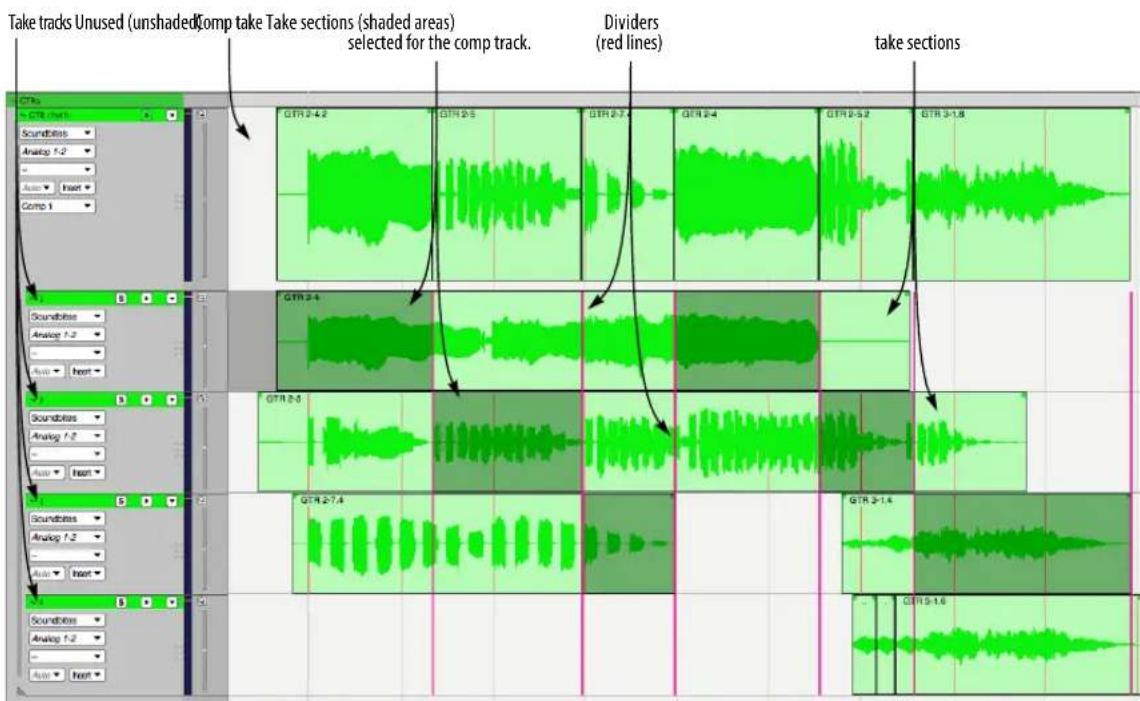
Figure 51-6: Building a comp take.
Divide Comp commands
The Divide Comp sub-menu in the Takes menu (Figure 51-7) provides several convenient shortcuts for creating comp divider lines.

Figure 51-7: The Divide Comp sub-menu.
At wiper
The at Wiper command (Figure 51-7) creates a divider line in the Take grid at the current playback wiper time.
At selection boundaries
If the current selection is an insert point, the at Selection Boundaries command (Figure 51-7) creates a single comp divider line in the Take grid at that insert point. If the current selection is a time range selection, this command creates two divider lines in the Take grid: one at the start of the selection range and one at the end of the selection range. For example, you could use the Scrub tool in a take track to zero in on the desired time range selection that you want, then choose Divide Comp at Selection Boundaries to create a comp region.
At selected soundbite boundaries
The At Selected Soundbite Boundaries command (Figure 51-7) creates a comp divider line at the beginning and end of each selected soundbite.
Comping Multiple Tracks Simultaneously
There are some cases where you might want to simultaneously comp two or more grouped tracks. For example, you might want to comp multi-tracked drums, or a bass/guitar track that you recorded direct on one track and amped on another.

In cases like these, you can collect the related tracks into a track group and use the “Show/Hide Takes” track group option to show and hide takes for all tracks in the group at the same time. Use the “Take comping” track group option if you also want to apply comping operations to all tracks in the track group simultaneously. That way, you can define comp regions and select takes in just one open take grid and have those choices take effect for all tracks in the track group. (Obviously, this is desirable only if each track in the track group has the same number of takes, and if the nth take on each track corresponds to elements of the same nth performance.)
TAKES AND KEY COMMANDS
There are key bindings for the items in the Take menu, as well as additional commands like Next Take and Previous Take. When invoked, these commands will affect all record-enabled tracks; if there are none, they will affect the selected tracks.
CONDUCTOR TRACK TAKES
The Conductor track holds tempo changes, meter changes, key changes and markers. However, switching takes on the Conductor track only affects tempo data. Meter changes, key changes, and markers are not affected by takes. For example, if you have a meter change at measure 3, as well as a number of tempo change events, and you choose New Take from the Conductor Track take menu, the tempo events will disappear from the track (as part of Take 1, which is being replaced by Take 2), but the meter change at measure 3 will remain.
Also, as there can be only one Conductor Track in a sequence, the Turn Takes into Tracks and Absorb Selected Tracks commands are not available for the Conductor Track.
TAKES INTERACT WITH MULTIPLE MIXDOWNS
See “How mix mode impacts your sequencing” on page 848 for an important discussion about how working with multiple mixdowns in the Mixing Board interacts with takes.
CHAPTER 52 Tempos and Audio
OVERVIEW
This chapter explains how to:
■ Apply tempo maps to soundbites
■ Extract tempo maps from soundbites that already have them
■ Make soundbites follow the tempo of a sequence, including tempo maps with ritards, accelerandi, and rubato
■ Make a sequence follow the tempo of a soundbite
■ View and edit embedded soundbite tempo maps
For information about a related feature, see chapter 53, “Audio Beats and Tempo Detection” (page 681) and chapter 82, “Scale Time” (page 947).
Soundbite Tempo Maps ....673
The track Stretch layer....674
Audio menu > Soundbite Tempo .....675
Set Soundbite Tempo....675
Clear Soundbite Tempo....676
Halve/Double Soundbite Tempo....676
Find Tempo Factor Near Sequence Tempo ....676
Copy Sequence Tempo to Soundbite ....676
Adjust Soundbites to Sequence Tempo ....677
Adjust Sequence To Soundbite Tempo ....678
Viewing and editing soundbite tempo maps.....679
Tempo menu....680
SOUNDBITE TEMPO MAPS
In order to make time-scaling musically useful, Digital Performer allows soundbites to have tempo maps. This makes it very easy for you to manipulate audio along with MIDI without worrying about the tempo, and change the tempo however and whenever you want.
When you record audio in time with the project time line, the new soundbite “knows” about the tempo map in effect at the time it was recorded, whether in manual tempo mode, or using a conductor track with tempo changes. Then, you may modify the tempo changes in the conductor track any way you like — using the Event List or MIDI Editor, manually or with the Scale Tempos or Change Tempo commands. At this point, the audio will no longer be lined up properly with any MIDI data in your sequence. All you need to do is enable the Stretch layer (“Stretch” on page 149) for the track and everything is perfectly aligned again! Digital Performer time-scales the soundbites, conforming their embedded tempo map with any tempo changes in the conductor track.
Audio beats and tempo detection
For audio that is not originally recorded in Digital Performer (in time with the project time line), Digital Performer can analyze the audio to detect beats and extrapolate the audio's tempo with a great deal of precision, even for long, complex tempo maps. The Waveform Editor provides many tools for refining the beat map and resulting tempo accuracy. See the next chapter, "Audio Beats and Tempo Detection" on page 681.
Working with soundbite tempo maps
This chapter explains how you can manually specify a soundbite's tempo, modify soundbite tempo maps and adjust the sequence to match the audio tempo, or vice versa.
An example of a soundbite tempo map
For now let's just consider the simplest case: a soundbite with a fixed tempo. The most common example of this case is a soundbite that was recorded to a click with a fixed tempo. If Digital
Performer knows the tempo of a soundbite, it can compute the exact duration, in beats and ticks. If you have configured the Soundbites window to show the “Duration (beat|ticks)” and “Tempo” columns, you will see this, as shown below in Figure 52-1. You can also view the tempos in the Waveform Editor as explained in “Viewing and editing soundbite tempo maps” on page 679.

Figure 52-1: The Soundbites window has two columns that show information about a soundbite's tempo map, if it has one: the TEMPO column, which shows the constant or average tempo, and the QUARTER | TICKS column, which shows its duration in quarter notes and ticks. You can show and hide these columns by double-clicking one of the column titles.
Viewing soundbite tempo maps in the Sequence Editor
In the Sequence Editor, Soundbites with tempo maps are drawn with gray lines on them, corresponding to the grid lines in the time ruler, as shown below in Figure 52-2.

Figure 52-2: A soundbite recorded at 120bpm in a 120bpm sequence (above), and the same soundbite placed in a 114 bpm sequence (below). Notice how the grid lines inside the soundbite no longer line up with the grid lines in the ruler to alert you to the fact that the soundbite tempo map doesn't currently match the sequence's tempo.
If a soundbite has a tempo map, the time ruler grid lines inside the soundbite stick to the audio data, not to the sequence. As a result, if a soundbite was recorded at 120 bpm, and you place it in a sequence with a tempo of 114 bpm, its gridlines won't line up with the time ruler grid lines to alert you that soundbite currently has a different tempo than the sequence. When this happens, the lines inside the soundbite are drawn in red, to further alert you to the discrepancy.
Ritards, accelerandi, and rubato tempos
Soundbites will usually have a constant tempo, but they are not required to. Each soundbite can essentially have an entire conductor track inside it! If you set up a conductor track with ritards and accelerandi, and record a soundbite, the soundbite automatically gets a copy of the current tempo map. If you later decide to change the conductor track, Digital Performer remembers the original tempo map with which the soundbite was recorded, and the audio will be stretched to remain in time with the new tempo (when the Stretch layer is enabled).
When the track Stretch layer is enabled for an audio track (Figure 38-13 on page 382), soundbites in the track will always remain conformed to the measures and beats of the project time line, as long as the soundbites have a tempo map that accurately reflects their tempo. The Stretch layer can be enabled on a per-track basis, so you can disable it for things like movie dialog tracks or sound effects tracks. For details, see “Stretch” on page 149.
AUDIO MENU > SOUNDBITE TEMPO
In addition to the automatic beat detection and tempo analysis features discussed in the next chapter, Digital Performer has several commands for manually creating or modifying a soundbite tempo map, as discussed in the following sections. These commands are found in the Audio menu >
Soundbite Tempo sub-menu. These commands are also available in the Tempo layer menu in the Waveform Editor (Figure 52-8 on page 679).
Selecting audio to apply tempo commands
Most of the Audio Tempo commands work on selected soundbites or selections within pop-edited soundbites. For time-ruler selections, they affect all soundbites that start within the selection. They can also be applied to selections in the Waveform Editor.
SET SOUNDBITE TEMPO
The Set Soundbite Tempo command (in the Soundbite Tempo sub-menu in the Audio menu) allows you to define a constant tempo for a soundbite or a portion of a soundbite. This is particularly useful with audio that was not recorded to the click, or that was obtained from a sample library, for instance. You can also make a selection within a soundbite while snapping to beats (see “Using the beat grid” on page 690) and quickly set the tempo based on the number of beats you have selected — very quick and easy.

Figure 52-3: The Set Soundbite Tempo command lets you define a constant tempo for a soundbite or a portion of a soundbite.
Make your audio selection (in any window) and choose Audio menu> Soundbite Tempo> Set Soundbite Tempo. The dialog shows the start and end times and length of the soundbite in real time (you may toggle between min:sec and SMPTE time). You may edit the end time in measures, beats, and ticks, or the duration in quarter notes and ticks. For instance, if you know the soundbite is two measures long in 4/4 time, just enter 8|000 — eight quarter notes exactly — into the duration box. Digital Performer instantly calculates the correct tempo. Alternatively, you may type in the tempo in beats per minute.
You may also use this command on a selection within a pop-edited soundbite. This comes in handy if you do not know the length of the whole soundbite, but it may be very easy to select two measures, or four measures — especially with beat grid snapping turned on as described in “Using the beat grid” on page 690.
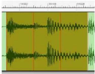
Figure 52-4: If you know the tempo of a portion of the soundbite, you can select just that portion and use Set Soundbite Tempo to apply a tempo.
What happens depends on whether the soundbite already has a tempo map or not. If the soundbite doesn't have a tempo map yet, a new tempo map is created using a fixed tempo for the whole soundbite. But if the soundbite already has a tempo map, only the tempo of the selected part of the soundbite is changed. This is one way of defining a varying tempo map for a soundbite.
The Set Soundbite Tempo command also works on selections in the Soundbites window. Note that in all cases, though, it only works on a single soundbite at a time.
This command has no effect on the audio data itself; it only affects the tempo map stored with the soundbite.
CLEAR SOUNDBITE TEMPO
The Clear Soundbite Tempo command (in the Audio menu> Soundbite Tempo sub-menu) removes the tempo maps from any selected soundbites.
HALVE/DOUBLE SOUNDBITE TEMPO
These commands (in the Audio menu> Soundbite Tempo sub-menu) divide or multiply an existing soundbite tempo map by a factor of two.
Sometimes, audio material can be misleading enough that DP's tempo analyzer chooses a tempo that is actually twice or half the actual tempo. For example, a very fast jungle/drum 'n bass break beat loop that is 170 BPM might be incorrectly detected at 85 BPM. To quickly correct errors like these, choose Audio menu > Soundbite Tempo > Double Soundbite Tempo or Halve Soundbite Tempo.
The audio in the file does not change (no time stretching occurs); just the tempo map is changed.
This command is also useful if you simply wish to play back the soundbite at twice or half its original tempo (in an audio track with Stretch enabled).
FIND TEMPO FACTOR NEAR SEQUENCE TEMPO
The Find Tempo Factor Near Sequence Tempo command (in the Audio menu> Soundbite Tempo sub-menu) scales the tempo map in the soundbite to match the sequence tempo as closely as possible. For example, if tempo analysis produces a tempo that is double or half the actual tempo of the audio, and you know that the soundbite's actual tempo is very close to the sequence tempo, this command will multiply or divide the tempo map by 1.5 (or 2, 3, 3.5, etc.) as needed to match the sequence tempo as closely as possible.
COPY SEQUENCE TEMPO TO SOUNDBITE
The Copy Sequence Tempo to Soundbite command (in the Audio menu> Soundbite Tempo sub-menu) copies tempo information from the sequence into any selected soundbites, replacing their existing tempo maps, if any.
Manual tempo mode vs. conductor track
If the sequence is in manual tempo (“Tempo Slider”) mode, it is the value of the tempo slider that is copied into the soundbites, not tempo changes from the conductor track. This command (as well as the ones described in the next two sections) always pays attention to the tempo that is actually being used by the sequence, whether it is the tempo slider, or the conductor track.

Figure 52-5: When copying the sequence tempo to a soundbite, Digital Performer takes into account the current tempo control setting. If it is set to Tempo Slider, the slider's current setting is mapped to the soundbite. If it is set to Conductor Track, the tempos in the conductor track are mapped to the soundbite.
This command does not work on selections in the Soundbites window.
ADJUST SOUNDBITES TO SEQUENCE TEMPO
Select a soundbite that is out of alignment with the sequence tempo (one with red lines in the Sequence Editor), and choose Audio menu> Soundbite Tempo> Adjust Soundbites to Sequence Tempo. Digital Performer time-scales the soundbite to make it line up exactly with the sequence tempo. This may require compressing some parts of the soundbite and expanding others. It may require dozens or hundreds of different
time scale factors. It doesn't matter, just choose this command, and Digital Performer does the rest.
If you would like soundbites in a track to always remain conformed to the sequence tempo, so that you don't have to take the time to do it manually with this command, see "Stretch" on page 149.
Only soundbites with tempo maps are affected. Also, any soundbites whose Time Compress/Expand preference in the Soundbites window is set to Don't Time Scale will be left alone. Furthermore, any selected soundbites that match the sequence tempo are left alone.

Figure S2-6: In this example, the soundbite "Rubato Piano" has a varying tempo map that does not match the sequence, as indicated by the uneven spacing of its grid lines (above). It is then shown mapped to the sequence, which has a constant tempo (below).
Background processing
This command does its work in Background Processing. The new unfinished soundbites will show up right away, and in the Sequence Editor you can see that the grid lines already line up properly with the sequence. See “Background Processing” on page 923.
ADJUST SEQUENCE TO SOUNDBITE TEMPO
This command does the opposite of Adjust Soundbites to Sequence Tempo. It copies the tempo map from any selected soundbites into the sequence. If you are in Conductor Track mode, this modifies the conductor track. In Tempo Slider mode, it sets the tempo slider to the average tempo from the selected soundbites.
This is useful when creating a new sequence from an existing soundbite. For example, if you have a drum loop from a sample library, you can give it a tempo map with the Set Soundbite Tempo command, or use the tempo map created by Digital Performer's Beat Detection Engine and automatic tempo analysis, and then copy that tempo into the sequence with Adjust Sequence To Soundbite Tempo.

line
| Time | Speed | |------|-------| | 0 | 120.00 | | 114 | 114.00 |Figure 52-7: In this example, a 114 bpm Drum Loop has been placed in a new sequence set to 120 bpm as shown by the tempo indication (above). After selecting the soundbite and choosing Adjust Sequence to Soundbite Tempo, the tempo slider now exactly matches the tempo of the soundbite, as indicated by the time ruler grid lines, which now match up (below).
As another example, you could import a full mix, or drum track stems for an entire song, and then make the sequence tempo map exactly match the imported audio. The basic procedure to do this would be:
1 Select the imported audio and choose Audio menu > Analyze Beats and Tempo.
2 Nudge all of the audio so that the first downbeat of the audio aligns with a measure downbeat.
You can also accomplish this with "Sync points" on page 399.
3 Set the sequence to Conductor Track tempo mode.
4 Select the audio and choose Audio menu > Soundbite Tempo > Adjust Sequence to Soundbite Tempo.
VIEWING AND EDITING SOUNDBITE TEMPO MAPS
To view the tempo map in a soundbite, open the soundbite in the Waveform Editor and choose the Tempo edit layer from the Edit layer menu (Figure 52-8).
Waveform Editor measure|Beat ruler
The Waveform Editor can display time rulers in any of Digital Performer's four time formats: measures/beats, real time, SMPTE time code, and/or samples. You can show and hide any combination of these four rulers using the "Time Formats window" on page 100.
Editing tempos directly in the tempo edit strip
In the Waveform Editor's Tempo tab, you can view, insert, modify, delete and otherwise manipulate the tempo map in the audio file currently being viewed in the Waveform Editor.

Figure 52-8: Viewing and editing an audio file's tempo map in the Waveform Editor via the Tempos tab.
Tempo Events
Tempo events are shown superimposed over the audio waveform. Their location is measured by the time line ruler above. Their vertical position indicates the value of the tempo event, as measured by the BPM (beats per minute) ruler on the left. The exact tempo is shown on the tempo event.
Editing Tempos in the Tempo Edit Strip
Because tempo editing is so closely tied in with the time ruler, tempo editing is done in the tempo edit strip (Figure 52-8) just below the ruler. Each tempo has a circular tempo handle (Figure 52-8). Use the tempo handles to edit tempos as follows:
To do this: Do this:
| To move a tempo event Drag its handle. The tempo events immediately preceding and following the one you drag serve as anchor points, constraining (“rubber-banding”) the results between them. | |
| To move a tempo event and adjust all subsequent tempo events | Hold down the Control/Win key while dragging the tempo handle. The tempo event immediately preceding the one you drag serves as an anchor point, but all subsequent events move with the one you are dragging. |
| To insert a tempo event Click in the tempo edit strip with the arrow cursor | |
To delete a tempo event Click its handle with the Mute tool.
You can use the snap-to-grid and snap-to-beat check boxes to constrain your tempo edits, if desired. Snapping to beats can be particularly useful for quickly adjusting the tempo map to match beats and tempo of the audio.
TEMPO MENU
The Tempo menu in the Waveform Editor (Figure 52-8) is activated by selecting the Tempo edit layer. The Tempo menu contains the same commands as found in “Audio menu > Soundbite Tempo” on page 675 (and subsequent pages), except for the additional commands noted below.
Analyze Soundbite Tempo
The Analyze Soundbite Tempo command engages Digital Performer's automatic tempo analysis features to generate a tempo map for a soundbite. This can be applied to any audio that has been beat-analyzed by Digital Performer's Beat Detection Engine; ensuring the audio file's beats are optimal before choosing this command can improve results. See “Editing beats to improve tempo detection” on page 694.
Set/Clear Soundbite Tempo
See “Set Soundbite Tempo” on page 675 and “Clear Soundbite Tempo” on page 676.
Clear Tempos in Selection
To use this command, select a portion of the waveform. Tempos within the selection are removed and anchor tempos are inserted, if necessary, at the boundaries of the selection to maintain the tempos before and after the selection.
CHAPTER 53 Audio Beats and Tempo Detection
OVERVIEW
This chapter gives you a brief overview of Digital Performer's beat detection and tempo analysis features, which give you unprecedented rhythmic and tempo control over your audio.
The Beat Detection Engine ....681
What works and doesn't work....682
Enabling preemptive beat and tempo detection .....682
Manually applying beat and tempo detection .....683
Where beats and tempo maps are stored....683
Viewing beats in the Sequence Editor....683
Editing beats in the Waveform Editor ....684
Beats menu ....685
Audio menu > Audio Beats .....687
Using the beat grid....690
Stretching audio beats ....691
Quantizing beats within soundbites....692
Applying a groove to beats within soundbites....693
Extracting a groove from audio....693
Ideas for quantizing audio....694
Beats determine tempo detection .....694
Editing beats to improve tempo detection .....694
Reanalyzing tempo after editing beats ....695
Adjusting soundbite tempo maps ....695
THE BEAT DETECTION ENGINE
Using sophisticated transient detection algorithms, Digital Performer's Beat Detection Engine can analyze any audio loop or audio file that contains rhythmic music and determine where the beats are in the music. After the beat locations have been determined, a wide variety of beat-related operations can be performed on the audio, giving you unprecedented rhythmic control over your music. For example, you can quantize — or apply a groove to — the audio without breaking it up into separate soundbites. Instead, Digital Performer applies time-stretching between beats.
As another example, you can snap edits and selections directly to beats for quickly making beat-accurate loops, beat-relative split points, and much more.
After the Beat Detection Engine analyzes an audio file for beats, state-of-the-art tempo analysis technology can then be applied to determine the overall tempo of the file. After a tempo map has been determined, a wide variety of tempo-related features can be applied, such as conforming the audio to the sequence tempo, or generating a conductor track tempo map that precisely matches the audio file's tempo.
The Beat Detection Engine can be highly accurate, depending on the nature of the audio material being analyzed. In most cases where a correct beat is found, the beat detection is sample accurate: it finds the exact sample where the beat transient begins. As a result, rhythmic manipulation, such as quantizing, groove extraction and groove application, will feel very accurate — or as they say, “in the pocket”.
Digital Performer's beat detection features are designed to be smoothly integrated into the overall operation of the program. You can set up beat and tempo analysis preferences and then take advantage of Digital Performer's powerful rhythmic editing and tempo-based processing during the course of your uninterrupted workflow.
WHAT WORKS AND DOESN'T WORK
Digital Performer's Beat Detection Engine and Tempo Analyzer are highly developed technologies. However, they have their limits. If an audio file has no rhythmic information in it whatsoever, then clearly beats and tempos won't be found. Examples of such audio include:
■ Ambient pads with smooth changes between chords
■ Percussion tracks with intermittent bursts of playing, separated by long silences (like a crash cymbal track)
■ Non-musical sound effects
■ Dialogue tracks
These are extreme examples, but they serve to illustrate one extreme: material that has no beats at all — or any sense of musical pulse.
Audio files with embedded beat and tempo information
What's the other extreme? There are many cases where audio files already have embedded tempo information. Below are a few examples:
■ Audio recorded directly in Digital Performer (and played to a click or other tempo reference to match DP's beats and barlines)
■ ACID WAVE files
■ REX (Recycle) files
■ Apple Loops
If an audio file has an embedded tempo map, then it won't require tempo analysis in order for you to make it conform to the tempo of your Digital Performer project. Digital Performer simply uses the existing tempo map. However, if you wish to quantize the audio or perform other beat-related operations, you will still need to analyze it for beats (even if it is a REX file or Apple Loop).
Rhythmic audio with no embedded tempo information
Digital Performer's Beat Detection Engine and Tempo Analyzer are intended for the middle ground between the two extremes just discussed and work best on audio files that have the following characteristics:
■ The audio file has no embedded tempo information already.
■ The audio material in the file has a perceptible rhythmic pulse.
■ The audio file represents a single instrument or drum track.
■ The audio material is not a full stereo mix.
The Beat Detection Engine is primarily designed for individual instrument parts that are rhythmic in nature and have a relatively steady tempo. It can often do a good job on complete mixes, but it is not fine-tuned for such material. However, you can often get great results, even on complete mixes, with a little bit of tweaking — far less work than would be needed using other much more painstaking techniques. For details, see “Editing beats to improve tempo detection” on page 694.
ENABLING PREEMPTIVE BEAT AND TEMPO DETECTION
If you plan to work with the many powerful and convenient beat- and tempo-related features discussed in this chapter, it is strongly recommended that you enable preemptive background beat detection and tempo analysis. This avoids the inconvenience of applying the processing manually, each time you wish to apply a beat- or tempo-related operation to an audio file. Instead, you can freely manipulate the beats and tempos of your audio without needing to keep track of what's already been analyzed or not.
To enable preemptive analysis, choose Preferences from the Digital Performer menu (macOS) or Edit menu (Windows) and click the Background Processing list item. The Beat and Tempo Analysis preferences (Figure 79-2 on page 928) let you choose when to apply the processing. See “Beat and tempo analysis” on page 929.
MANUALLY APPLYING BEAT AND TEMPO DETECTION
If, for some reason, you choose not to use Digital Performer's preemptive background beat detection and tempo analysis, you can manually apply beat and tempo analysis to any selected soundbites or audio files.
To manually initiate beat analysis on individual soundbites, first select them in the Sequence Editor or Tracks Overview and then choose the Find Beats command (Audio menu > Audio Beats). This command opens a window that allows you to preview the beats found within the selected soundbites before applying them to the soundbite, with a slider to vary the analysis sensitivity setting of the beat detector. See “Find Beats” on page 685 for more information.
Alternatively, select the audio file in the Waveform Editor, open the Beats edit layer (Figure 53-2 on page 684) and choose Find Beats in the Beats menu.
Similarly, if beats are present in an audio file and you would like to manually initiate a tempo analysis, first select the soundbites in the Sequence Editor, Tracks Overview or Soundbite List and then choose Analyze Soundbite Tempo (Audio menu > Soundbite Tempo). This can also be done in the Waveform Editor by selecting the audio file, opening the Tempo edit layer (Figure 52-8 on page 679) and choosing Analyze Soundbite Tempo in the Tempo menu.
Tempo analysis results depend on the quality of the beats detected in the audio file. Manually altering some beats in the Waveform Editor's Beats edit layer and then initiating a tempo analysis can improve tempo detection. See “Editing beats to improve tempo detection” on page 694 for further information.
WHERE BEATS AND TEMPO MAPS ARE STORED
Beat information is stored with the Digital Performer project and therefore does not transfer from one project to another.
The audio file's tempo map is stored with the audio file itself. Therefore, if the audio file is imported into another DP project, the tempo map is also imported and can be used to make the audio conform to the tempo map in the new project.
VIEWING BEATS IN THE SEQUENCE EDITOR
After a soundbite has been beat analyzed, the beats can be viewed in the Sequence Editor as faint vertical lines, as shown in Figure 53-1. You can show or hide these lines with the Show beat grid lines preference (“Edit Window guides” on page 91). They cannot be edited in the Sequence Editor: to edit them, use the Waveform Editor as explained in “Editing beats in the Waveform Editor” on page 684.
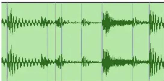
natural_image
Audio waveform visualization with green oscillating peaks and vertical alignment markers (no text or symbols)Figure 53-1: Beats appear as faint vertical lines in the Sequence Editor.
EDITING BEATS IN THE WAVEFORM EDITOR
To view and edit beats, open the soundbite in the Waveform Editor and select Beats from the Edit Layer Menu at the bottom of the window, as shown in Figure 53-2. Beat editing allows you to make specific adjustments or corrections to individual beats, add them, delete them, and so forth. In turn, these adjustments can produce better results when applying beat-based edits, such as quantizing, groove extraction, etc.
Beat editing
Beats (Figure 53-2) appear as vertical lines at the beginning of transients (spikes) in the audio waveform. Drag a beat left or right to adjust its position, relative to the actual audio. Doing so does not alter the audio; it merely adjusts Digital Performer's notion of where the beat is.
Adding and deleting beats
To add a beat, select the pencil tool and click the Waveform display at the point where you would like to add the beat. The vertical position of the cursor will correspond to the new beat's velocity.
To delete beats, simply select them and choose Edit menu > Erase, or simply hit the backspace key.
Selecting beats
To select a beat, click it. It then appears as a heavier line, with a tab at the top of the beat line (Figure 53-2).
You can select any number of beats by shift-clicking unselected beats, or by making a time range selection with the I-beam cursor to select all beats within the selection. You can then apply a number of beat-related commands to the selected beats using the Beats menu.

Figure 53-2: Viewing and Editing beats in the Waveform Editor.
Beat velocity
In addition to placement, beats are also analyzed for their strength, relative to the other beats around them. The strength of the beat is represented by the beat's velocity handle (Figure 53-2), which can be adjusted by dragging the handle vertically. Move up the slider to increase velocity; move it down to lower velocity. Beat velocity translates into MIDI note-on velocity when copying beat data as MIDI using the Copy Beats as MIDI command in the Audio menu and Beats menu (Figure 53-2), or when extracting the audio's groove using the Create Groove command (Region menu).
Disabled beats
There may be times when you wish to disable a beat. When a beat is disabled, its location is remembered, but it is ignored for all beat- and tempo-related operations. You can re-enable it at any time by selecting it and choosing Toggle Selected Beats in the Beats menu, as explained in the following sections.
To disable a beat, click it with the Mute tool in the Tool palette (Figure 36-1 on page 347).
BEATS MENU
The Beats menu (Figure 53-2 on page 684) offers several convenient features for working with soundbites.
Find Beats
The Find Beats command opens a window that allows you to add beats to selected soundbites, detected using Digital Performer's beat detection algorithm. Once a soundbite has been selected, the algorithm will find the beats and display a preview. Click Apply to save these beats to the soundbite.
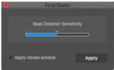
Figure 53-3: Find Beats.
The slider in the window adjusts the sensitivity setting, which alters how sensitive the beat detection algorithm is when finding beats in audio. A low sensitivity setting means the beat detector will detect fewer beats, and a high sensitivity setting will lead to more beats being found. Move the slider to the right to increase the sensitivity setting, or move it to the left to lower it: the preview will update the results accordingly. After clicking Apply the new sensitivity setting will be remembered so that any future beat detection on that audio file will use the updated sensitivity level by default.
There are situations in which it is useful to alter this setting. For example, in a live recording, audience noise or chatter could be mistaken for beats. In this case a lower sensitivity would remove these false positives. As another example, increasing the sensitivity would yield better results in recordings with very quiet transients.
In general, lowering the sensitivity setting reduces the detection of false positives while increasing the sensitivity will find more beats.
The Find Beats command is also available in the Audio menu so that you can use it on selected soundbites in the Sequence Editor, too.
Clear Beats
The Clear Beats command removes all the beats from the audio file.
Toggle Selected Beats
Choose Toggle Selected Beats to either enable or disable the currently selected beats. If the selected beats are a mixture of enabled and disabled beats, this command will disable the previously enabled beats and leave the previously disabled beats the same. If all the selected beats are the same (either all enabled or all disabled) it will toggle them all.
Disable Beats under Strength Threshold
Choose Disable Beats under Strength Threshold to open a window with a slider that lets you enable or disable beats based on a strength threshold.
This window applies to the beats within the current selection; you can make a selection before or after you open this window (with the window open). If there is no selection, it applies to all the beats in the file. No changes are made to beats until you click the Apply button.
Move the slider towards the right to disable more beats; move it to the left to disable fewer beats. Click Apply when you have the desired result. You can quickly disable or enable a large number beats in one operation using this command.
The Disable Beats under Strength Threshold command is also available in the Audio menu so that you can use it on soundbites in the Sequence Editor, as well as audio being displayed in the Waveform Editor.
Delete Selected Disabled Beats
The Delete Selected Disabled Beats command gets rid of all the selected disabled beats.
New Soundbite from Active Beat
Choose New Soundbite from Active Beat to create a soundbite that begins at the active beat and ends at the next beat.
Copy Beats as MIDI
Choose Copy Beats as MIDI to create a MIDI data stream with a MIDI note corresponding to each beat; each note's start time is the relevant beat's start time, and the note's velocity is that beat's strength. The end time of each note is set just before the following note's start time. This MIDI data will then be placed in the Clipboard and, like all copied MIDI data, it can be pasted to any MIDI track.
If there are selected beats, this command will only construct MIDI notes corresponding to the selected beats. If not it will copy all the beats in the audio file as MIDI.
Creating MIDI data from audio beats is useful if you want to trigger MIDI drum hits or notes synced with the transients of an audio file. Manually entering MIDI data to accomplish this is time consuming and inaccurate.
The Copy Beats as MIDI command is also available in the Audio menu so that you can also use it on soundbites in the Sequence Editor.
Play Beats as Clicks
Choosing Play Beats as Clicks enables clicks to play at detected beat times during playback when in the Beats edit layer in the Waveform Editor (Figure 53-2 on page 684).
The main purpose of this feature is to audibly check whether the detected beats are in the right place, or if there are any missing beats.
Often, transients are impossible to locate visually, and thus playing beats as clicks is a quick and accurate way to help place them.
Beat Click Preferences
Choosing Beat Click Preferences opens the Click Preferences and allows you to choose the audio file used as the Beat Click, as well as its volume. There
are many samples to choose from, and you can also use any audio file you please using the Choose File menu item.
AUDIO MENU > AUDIO BEATS
The Audio Beats sub-menu (in the Audio menu) has several commands for managing audio beats. Some of these commands are also found in the Beats menu in the Waveform Editor (Figure 53-2 on page 684). Digital Performer gives you access to them in the main Audio menu as well so you can easily apply them to selected soundbites in the Sequence Editor or Soundbites list.
Find Beats
The Find Beats command (Audio menu > Audio Beats) lets you find beats in selected audio files using Digital Performer's Beat Detection Engine, with the ability to tweak the sensitivity level of the beat detection algorithm. For details, see "Find Beats" on page 685.
Clear Beats
The Clear Beats command (Audio menu > Audio Beats) removes all the beats from selected audio files.
Disable Beats under Strength Threshold
The Disable Beats under Strength Threshold command (Audio menu > Audio Beats) lets you control how many beats are enabled or disabled in a soundbite based on their velocity threshold. For details, see “Disable Beats under Strength Threshold” on page 686.
New Soundbites from Beats
The New Soundbites from Beats command (Audio menu > Audio Beats) lets you split up a soundbite into pieces at beat boundaries. This can be useful when making drastic tempo changes that would not be suitable for time stretching beats within a soundbite. In addition, there may be other circumstances where smaller split up regions can be more useful than whole soundbites. When you choose the New Soundbites from Beats command, a window appears with a slider in it:

Figure 53-5: Creating soundbites from beats.
Select the soundbites you wish to split up (or make a time range selection) in the Sequence Editor. You can select the audio you wish to split up either before or after you open the New Soundbites from Beats window, and you can change your selection at any time before you click the Apply button. Before you click Apply, you'll see a preview of where the splits will take place:

Figure 53-6: A selected soundbite with preview slices for the New Soundbites from Beats command.
Controlling the frequency of the splits
Move the slider to control how frequently the soundbite will be split up. Split points are added or removed from the operation based on their associated beat velocity. As you move the slider, beat velocities fall either above or below the threshold, to be included or excluded, respectively.
Splitting audio across multiple tracks
If you are splitting a single soundbite, or several soundbites that are all in the same track, choose Each Soundbite from Use Beats From menu.
If you are splitting audio in multiple tracks across the same time range, the Use Beats From menu gives you two basic choices:
| To do this | What to choose from the Use Beats From menu |
| 'To split each track independently | Choose Each Soundbite |
To split all tracks at the same Choose the track that you wish to locations, based on a guide track use as a guide track
Figure 53-4 below demonstrates the difference between using the Each Soundbite setting and using a guide track. Using a guide track can be useful when you need to edit consistently across all of the tracks involved. If they all share the same split points, this will help your edits remain consistent, especially with regard to maintaining phase coherence. This can be especially critical when editing drum tracks that were recorded simultaneously from different mic positions.
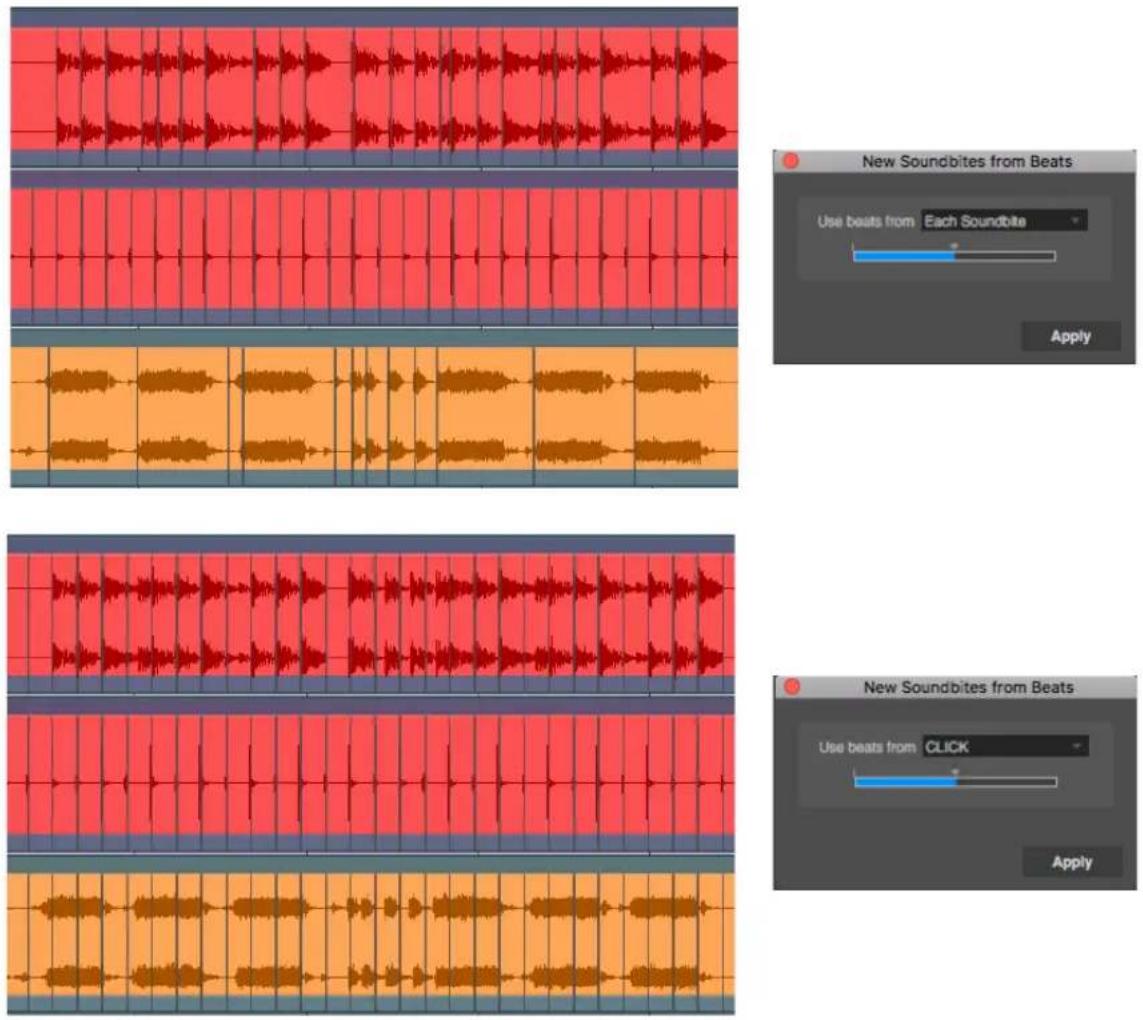
Figure 53-4: Using the 'Each Soundbite' setting versus using a guide track
Using Smooth Audio Edits after creating soundbites from beats
A common application for the New Soundbites from Beats operation is to split up a drum track or percussion track and then slow down the tempo of the sequence. Typically, time-stretching audio to slow it down can produce artifacts. By splitting up the audio beforehand, a minimum of time stretching occurs, and instead, gaps appear between the individual drum track slices as they are moved further from one another by the slower playback tempo. This technique is good because it minimizes audio time stretching artifacts.
However, the trade-off is that the gaps of silence between the slices are audible and sound unnatural. The Smooth Audio Edits feature can be a huge help in this situation by filling the gaps with room tone or other ambient noise that fills and completely masks the gaps between the slices. Numerous options are provided to produce the best results, based on the audio material. For details, see “Smooth Audio Edits” and “Smooth Audio Edits Again” on page 649.

Figure 53-7: In this example, beats are being copied from the click track to the guitar and drum tracks.
Copy Beats
In multitrack audio recording projects, it is often useful to take the beats from a guide track and apply them to other tracks so that their beats match the guide track. You can then apply beat-based edits or processing consistently across the tracks.
For example, you might have a kick and snare track that represent the beat structure of your music perfectly, and you might wish to apply it to a highly syncopated conga track so that its beat-based edits are more consistent and in line with the overall music.
The Copy Beats command (Audio menu > Audio Beats) lets you copy beats from one track to another. When you choose the Copy Beats command, a window appears:
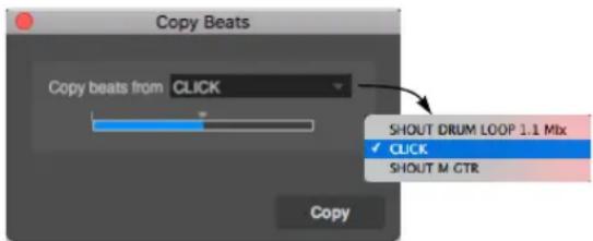
Figure 53-8: The Copy Beats command.
Select both the source and destination soundbites or tracks. You can select them either before or after you open the Copy Beats window, and you can change your selection at any time before you click the Copy button. Before you click Copy, you'll see a preview of the beats that will be copied, as shown in Figure 53-7 on page 689.
Choosing the source track and beat frequency
Choose the desired source track from the Copy beats from menu, as demonstrated in Figure 53-7. Move the slider to control the frequency of the beats to be copied. Beats are added or removed from the operation based on their associated beat velocity. As you move the slider, beat velocities fall either above or below the threshold, to be included or excluded, respectively. After you have the beat slider set as desired, click Apply.
Copy Beats As MIDI
Choose the Copy Beats as MIDI command to generate in the clipboard a stream of MIDI notes corresponding to the audio beats of a selected soundbite in the Sequence Editor. This can then be pasted into any MIDI track. This operation can also be applied in the Beat layer of the Waveform Editor. See “Copy Beats as MIDI” on page 686 for details.
USING THE BEAT GRID
The Beat Grid in the Snap Information panel (Figure 53-2 on page 684) snaps your selection and edit operations to the beats within the waveform. Editing to the Beat Grid is different than editing to the time ruler Edit Grid. With the Edit Grid, your actions snap to the specified beat resolution at regularly spaced intervals that are prescribed by Digital Performer's time ruler. But with the Beat Grid, your actions snap to actual beats within the waveform, as specified by the beat locations in the waveform, even if they don't match up with beats in the time ruler.
Essentially, the Beat Grid allows you to edit to the audio data, instead of to the project's time ruler. This is very powerful, especially when making edits that must remain faithful to the feel or "groove" of the audio, as this would not be reflected in the time ruler grid. Further, Digital Performer's Beat Detection Engine goes to great lengths to place beats at exact transient onsets, usually down to the sample. This makes beat editing extremely accurate.
Beat Grid snapping works similarly to marker snapping: when you drag close to a beat, it snaps. But if you are not close to a beat, it won't snap.
The Beat Grid can be enabled with the Snap to Beats checkbox in the Snap Information window, and can be used in the Waveform Editor or the Sequence Editor. In the Sequence Editor, you can extend the selection across multiple audio tracks. In this case, your actions snap to the beats in the track under the cursor, so move the cursor over the track that contains the beat you wish to snap to.
If the Beat Grid is currently turned on, hold down the Command/Ctrl key to temporarily turn it off.
You can enable the Edit Grid, the Beat Grid and marker snapping at the same time, if you wish. In this case, your actions will snap to all three.
STRETCHING AUDIO BEATS
You can use beat markers to move — or stretch — their corresponding audio beat earlier or later in time, relative to the surrounding beats. This lets you seamlessly tweak the timing of individual beats in your audio.
In the Waveform Editor, choose the Stretch edit layer, as shown in Figure 53-9. Grab the beat you wish and drag it left or right. Use the Snap to Grid setting to determine the anchor points on either side of the beat you wish to drag, represented by purple lines. You might need to experiment a little bit to find the right grid setting, depending on the material. You can include surrounding beats if you wish, but if you only want to stretch the beat you are grabbing, choose a grid setting small enough that the surrounding beats don't move when you drag the beat.
You can stretch as many audio beats as you wish in the Stretch layer.

Figure 53-9: The Stretch layer in the Waveform Editor. The Snap to Grid setting determines the anchor points surrounding the beat you drag.
Adjusting anchor points
If needed, you can drag the anchor points themselves using the arrow cursor shown in Figure 53-9. This gives you more control over the span of the audio affected by your adjustment. Often, anchor points have an initial position on an beat marker. Simply move the cursor over the purple line until it appears as an arrow cursor (rather than the hand cursor, which drags the beat itself). The arrow cursor moves the anchor point.
Clearing stretch edits
To clear a stretch edit, click the beat marker to select it (it turns yellow) and either hit the backspace key or choose Edit menu > Erase. You can also make a time range selection to clear multiple stretch edits in one operation. To clear all stretch edits in a soundbite, select it and choose Audio menu > Pitch and Stretch > Clear Bite Stretch.
Stretching audio beats in the Sequence Editor
You can also stretch audio beats directly in the Sequence Editor. The procedure is basically the same as described above: choose the Stretch edit layer for the track (see Figure 38-10 on page 380 and “The Edit Layer” on page 381) and use Snap to Grid to determine the span for the anchor points. Also be sure that the Stretch layer is enabled in the track settings (“Stretch” on page 149).
Quantize, Groove Quantize and beat stretching
If you quantize or groove quantize beats within audio (as explained in the next few sections), those operations will override any manual beat stretching you've done to the audio. Conversely, however, you can certainly make manual tweaks to beats after applying Quantize or Groove Quantize, to further tweak the feel of the audio beats post quantizing.
QUANTIZING BEATS WITHIN SOUNDBITES
Soundbites that have been beat-analyzed (and have beats) can be quantized, without the need for splitting them into smaller soundbites first. Instead, the beats within the soundbite are quantized by many small time-stretching operations between each beat. Audio quality is preserved, and each beat is moved, just like MIDI notes, according to the settings in the Quantize dialog.
In general, quantizing beats within soundbites will produce best results when the soundbite has already been tempo-analyzed (as described later in this chapter) and has been adjusted to match the tempo of the sequence. Quantizing then fine-tunes beat placement with respect to the project's time ruler grid.
To quantize the beats within a soundbite:
1 Select the soundbite and choose Region menu> Quantize (Figure 48-12 on page 603).
2 From the What to quantize menu, choose Beats within Soundbites and Attacks (if you are quantizing both audio and MIDI notes).
3 Choose the other settings in the Quantize dialog as desired.
When quantizing beats within audio, the Attacks, Releases and Don't change note durations options are ignored, as these three options apply to MIDI notes only. The rest of the settings in the Quantize dialog apply to both MIDI and audio, including tuplet quantization, grid offset, swing, sensitivity, strength and randomize.
4 Click Apply.

Figure 53-10: Quantizing beats within audio.
Beats within audio quantize differently than MIDI notes
Beats within audio quantize slightly differently than MIDI notes. When you quantize MIDI notes, every single note moves to the nearest grid point (subject to the other settings you may have specified, such as strength, etc.) However, this is not the case for beats within audio. Instead, Digital Performer employs a more useful algorithm, which moves only the beat closest to each grid point and then smoothly scales all others between them. This produces much more useful results for audio, as it time-stretches the audio as little as possible while still achieving the desired quantizing results. As long as you choose a grid resolution that is appropriate for the audio (e.g. a 16th note grid for audio that has a 16th note subdivision pulse), then you'll get great results.
Previewing
The real-time Preview button in the Quantize window (Figure 48-12 on page 603) only previews the quantize effect for MIDI data. It does not provide a real-time preview for beats within audio.
Audio stretch and quantizing
The Stretch audio track setting (“Stretch” on page 149) has an impact on quantizing beats within audio. If it is enabled, quantizing occurs in the Stretch layer of the track. This means that any stretch edits you’ve previously made to the material being quantized will be replaced by the quantize operation. In addition, you can go into the Stretch layer after quantizing and view the results of the quantizing, as explained in “Stretching audio beats” on page 691. You can even further hand-tweak beat locations, if you wish.
APPLYING A GROOVE TO BEATS WITHIN SOUNDBITES
Applying a groove to beats within soundbites works in a similar fashion as described above for quantizing. Select the soundbite and choose Region menu> Groove Quantize. In the case of Groove Quantize, however, there is no What to Quantize setting. The groove is applied to any selected MIDI notes and any beats within selected soundbites. All settings in the Groove Quantize window are applied to audio. The velocity slider applies the appropriate value to beat velocities. If the Stretch layer is enabled, you can further hand-tweak individual beats in the Stretch layer afterwards.
EXTRACTING A GROOVE FROM AUDIO
To extract a groove from audio, select the audio in any window and choose Region menu> Create Groove. Choose a groove file to save the new groove to, or create a new groove file. Name the groove and then click OK. Beat timing, velocities and duration are saved in the groove. You can then apply the groove to MIDI data and/or audio data.
IDEAS FOR QUANTIZING AUDIO
Digital Performer's audio quantize, groove quantize and groove extraction features are very powerful and offer many creative opportunities. Here are a few things you can do when quantizing or groove quantizing audio:
■ Take an existing audio recording with sloppy timing and quantize it to clean up the timing.
- Extract the rhythmic feel of an audio recording and then apply it to other audio tracks and/or MIDI tracks.
■ Turn a loop with a straight feel into a shuffle feel, using one of the MPC shuffles - or any other shuffle groove.
■ Tighten the timing of several rhythm section tracks (keys, bass, drum, rhythm guitar, etc.) by quantizing them with varying degrees of quantize strength.
■ Take an existing audio recording with slight tempo changes in it make it a constant tempo throughout.
BEATS DETERMINE TEMPO DETECTION
Digital Performer uses beats to determine tempo. Even if beats are found at somewhat irregular intervals, the tempo analysis can, in most cases, still discern the correct tempo.
The tempo analyzer builds a tempo map by determining which beats represent the music's barlines. Using this technique, the tempo analyzer is capable of creating sophisticated tempo maps that track long passages of recorded music. The tempo analyzer can save hours of painstaking tempo adjustments by tracking the tempo of your recordings automatically.
Since Digital Performer's beat detection is sample accurate, the tempo analyzer is capable of determining very precise tempos for audio. It works best on steady, rhythmic, monophonic audio, but it is capable of tracking complex music with multiple instruments or live recordings with room noise. In most cases it determines the correct tempo, but there are some audio files, particularly long files of mixed music with varying tempo, where it can choose the wrong tempo for sections of the music.
EDITING BEATS TO IMPROVE TEMPO DETECTION
Understanding how the tempo analyzer chooses tempos will allow you to guide its tempo detection. Often, only one or two adjustments to the beats in an audio file are needed in order for the tempo analyzer to compute the correct tempo throughout the file. By moving, enabling or disabling beats (as discussed earlier in this chapter) and reanalyzing the file's tempo, you can effect the decisions that the tempo analyzer will make.
The tempo analyzer will only place tempo changes directly on beats with the goal of choosing which beats to align with measure boundaries. When it chooses the wrong tempo, it has likely chosen a beat near a barline but one that is slightly ahead of or behind the barline. This causes the resulting tempo at that location in the file to be incorrect.
In this case, you can try moving the offending beat to the correct position, and then reanalyzing the file.
Other common cases are melody lines or vocals that are not precisely aligned with the barlines to which they were performed. For example, the singer might come in just a little early, before the beat. These vocalizations can be louder than other beats that would make better guides for the tempo analyzer. Disabling these beats will often produce more accurate tempos.
Here's another common case: often the rhythmic elements of the music are represented by the loudest beats. If so, you can use Disable Beats under Strength Threshold (page 686) to disable quieter beats.
Another technique that can dramatically improve tempo analysis is to select and disable beats that are not representative of the underlying rhythm. For example, you can focus on a snare drum or hi hat the is consistent with the rhythm and disable areas that contain sub-divisions or other beats. To check which beats are representative of the underlying rhythm, a useful tool is to enable the Beat Click. See “Play Beats as Clicks” on page 686.
REANALYZING TEMPO AFTER EDITING BEATS
In all cases, you can freely experiment with beat adjustments. Just reanalyze the tempo again. You can reanalyze tempo as many times as you wish.
ADJUSTING SOUNDBITE TEMPO MAPS
The Soundbite Tempo sub-menu (Audio menu) provides several useful commands for further adjusting soundbite tempo maps. See “Audio menu > Soundbite Tempo” on page 675.
CHAPTER 54 System Exclusive
Digital Performer allows you to record, playback, and edit MIDI System Exclusive (SysEx) messages. Common types of System Exclusive messages include patch dumps, preset selections, editing parameters, etc. Digital Performer can thus store patches, samples, and other important information from your MIDI equipment in system exclusive form. Patches, edit parameters, and other special commands can be incorporated into musical sequences, greatly expanding the resources of your MIDI sound modules.
Basics 697
Recording and playing SysEx messages....697
Viewing and editing SysEx data....698
Editing data in the system exclusive window....699
Inserting SysEx data in the event List ....700
Editing SysEx data with the Edit Menu ....700
Transmitting a SysEx message....700
Recording SysEx into the Editor Window....701
Recording SysEx into a track....701
Hints ....702
Be Careful ....703
BASICS
System Exclusive messages are a special type of MIDI data. A System Exclusive message consists of a header, body, and an 'end of message' byte. (A byte is a unit of digital information, roughly equivalent to a single character or letter.)
The header labels the following data as System Exclusive information, and includes a code identifying the manufacturer of the equipment transmitting the data.
The body of the message contains the actual data being sent. This data may take any form the manufacturer desires. There are some standards for the format of System Exclusive information,
but for the most part a System Exclusive message is only understood by the type of equipment that generated it. As a result, recording a patch dump from one synthesizer and sending it to another will generally not produce useful results. Digital Performer does not respond to or interpret System Exclusive data; any analysis or editing of the body of the message is the user's responsibility.
Finally, the end of message byte, F7, marks the end of the System Exclusive data, and signals Digital Performer to interpret subsequent information as standard MIDI data.
As defined in the MIDI specification, a System Exclusive message must begin and end with an F0 and F7 byte, respectively. In addition, only hexadecimal values of 7F (127 in base ten) or less are allowed. When you click the OK button after inserting or editing the contents of a System Exclusive event, Digital Performer will scroll to and highlight any bytes that violate the conditions just stated.
RECORDING AND PLAYING SYSEX MESSAGES
System Exclusive messages are recorded and played back like any other MIDI data. These messages vary in size; information for a bank of patches, for instance, may be 10-20K or more. No matter how long a message is, it is treated as a single event by Digital Performer. Note that a long System Exclusive message can briefly halt recording or playback as Digital Performer processes the data; it is best to place larger System Exclusive events like patch or bank dumps in separate sequences, or at the start of a sequence before the actual music begins.
Because System Exclusive messages have no channel assignment, they are sent to every MIDI device connected to a port. If you have several devices of the same model or brand connected to the same port they may all respond to a message sent to or from just one of them. Conversely, some manufacturers encode channel assignments into the body of the System Exclusive message. Digital Performer is unable to access or rechannelize such an assignment.
For example, if the playback assignment for a track is channel 1, but a System Exclusive message full of patches intended for that synth includes an encoded assignment to channel 16, the synth won't receive the patches.
Find out if any of your equipment encodes channel assignments in its System Exclusive messages, and be careful about changing channel assignments on equipment to which you intend to send System Exclusive. If you encounter difficulty when working with System Exclusive data, try patching the MIDI device directly to your MIDI interface to prevent interaction with other equipment.
Note that the Input Filter, found in Digital Performer's Setup menu, defaults to System Exclusive unchecked. Unless you explicitly check the box next to System Exclusive, you will be unable to record System Exclusive messages.
VIEWING AND EDITING SYSEX DATA
System Exclusive data can be viewed and edited in the Event List window for the track on which it is recorded. In an Event List, a System Exclusive message will consist of the System Exclusive symbol and as much data as can fit on one line:
1|4|113 □ <2832> F0 00 20 29 02 00 7F 00 00 13
To see the entire message, Option/Alt-click or double-click on the System Exclusive event. A window appears:
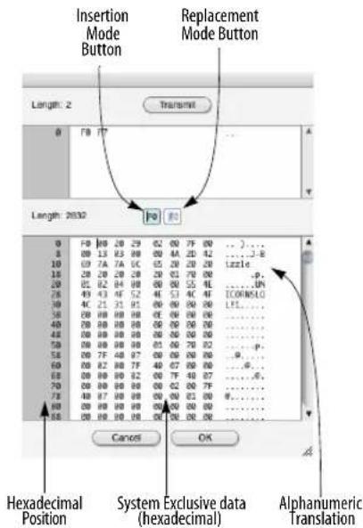
Figure 54-1: Digital Performer's system exclusive editor. The Transmit button transmits the message currently displayed in the upper portion of the display. Use it to send a SysEx request message to a device. The SysEx message the device sends in response will appear in the lower portion of the window.
The window is divided into a top and bottom portion. The bottom portion displays the system exclusive data contained in the event. The top portion is used to type in and transmit short system exclusive “request” messages, which can be sent to a synthesizer that requires a short system exclusive bulk dump request message to initiate a bulk dump to be recorded into the lower portion of the window.
The System Exclusive data is displayed in hexadecimal (base 16) numbering. Each pair of hexadecimal digits, which include the numerals 0-9 and the letters A-F, represents a byte of data. Each line contains eight pairs of digits. To the left of each line of data is a two-digit hexadecimal number indicating the position of the first byte of data in that row. The first row starts at position 00,
the next at 08, the third at 10 (this equals 16 in hexadecimal), and so forth. To the right of each row of data is its translation into alphanumeric characters (using the ASCII standard). Most of the time this translation will be garbled and useless, but patch names and other text in the System Exclusive message may be visible.
The length of the System Exclusive message is displayed at the top left. This is the number of bytes of data in the message.
The scroll bars let you scroll through long messages. The Grow box in the lower right corner lets you adjust the size of the window. When you press the OK button, Digital Performer checks the changes you have made to the data and will scroll to and highlight any byte that does not conform to the MIDI specification. After confirming your changes, Digital Performer closes the window. Pressing the Cancel button closes the window without making any changes to the data.
EDITING DATA IN THE SYSTEM EXCLUSIVE WINDOW
You can directly edit the hexadecimal data in the System Exclusive window using the mouse and computer keyboard. There are two basic editing modes: Insertion mode and Replacement mode. The editing mode is selected by clicking on the appropriate button at the top center of the window; the currently selected mode is indicated with a darkened border.
Insertion mode: This mode is similar to standard computer text entry. To insert new values, click the mouse to position the insertion point, and type in new values. Use the delete key to delete previous digits. You may edit only in the hexadecimal portion of the display.
Replacement mode: In this mode, one character is always highlighted. Typing a new character replaces the current highlighted character, and then highlights the next character. Use this mode if you are just changing a few bytes in a system exclusive message.

To edit a System Exclusive event:
1 Open the Event List window that contains the System Exclusive event.
2 Double-click on the System Exclusive event.
The System Exclusive window appears.
3 Select the editing mode.
Click on the appropriate button. If just a few bytes need to be edited, use Replacement mode. Otherwise, use Insertion mode.
4 Edit the data.
In Insertion mode, delete the incorrect bytes and type in new data. In Replacement mode, click on the first digit of data to be replaced and type in the new data. The old data is written over.
5 Press OK to confirm your changes and close the window, or Cancel to close the window without making any changes to the data.
If you press OK, Digital Performer will scroll to and highlight any byte that does not conform to MIDI specification requirements.
Cutting, Copying, and Pasting
To Cut, Copy, or Paste a selection of hex data in replacement mode:
1 Select the data.
To do so, drag over it with the mouse.

2 Cut, copy, or replace the selection.
To Cut or Copy, press Command/Ctrl-X or Command/Ctrl-C respectively. The selected data will be placed in the Clipboard. To replace the selected data, type in or paste new data, which will replace the highlighted data.
INSERTING SYSEX DATA IN THE EVENT LIST
You can insert system exclusive data into the Event List window. This is handy for inserting a short system exclusive message, like a parameter change or dump request, without having to record it. The following steps apply to System Exclusive insertion in an Event List. Refer also to chapter 39, "MIDI Editor" (page 411).
To insert a System Exclusive event into an Event List:
1 Open the Event List into which you want to insert the System Exclusive event.
2 Choose System Exclusive from the Insert menu.
3 Press the Insert button.
A new system exclusive event pops up.
4 Enter the location for the system exclusive event.
5 Press the Tab key to move to the data field.
The System Exclusive window appears.
6 Select Insertion mode.
Click on the Insertion mode button at the center of the window.

7 Type in the data.
In Insertion mode, you can delete the incorrect bytes and type in new data. See the above section on editing System Exclusive data for more information.
8 Press OK to confirm the insert and close the window, or Cancel to cancel the insert and close the window.
When confirming your insert, Digital Performer will scroll to and highlight any byte that does not conform to MIDI specification requirements.
EDITING SYSEX DATA WITH THE EDIT MENU
The commands on the Edit menu work as normal on System Exclusive events; these events can be cut, pasted, shifted, etc. within a file or between files just like any other Digital Performer event. The only way to alter the body of a System Exclusive message is to use the System Exclusive window as described above. In all other cases, Digital Performer treats the message as a single event.
TRANSMITTING A SYSEX MESSAGE
To transmit a system exclusive message from the system exclusive editor window:
1 Click the insertion mode button.

2 Click between the F0 and F7 in the top portion of the window.
3 Type in the system exclusive data.
4 Click Transmit.
RECORDING SYSEX INTO THE EDITOR WINDOW
To record system exclusive into the system exclusive editor window:
1 Be sure that your MIDI hardware and cables are set up properly.
Make sure there is a MIDI cable from the MIDI OUT on the device you will be recording from to the MIDI IN on your interface.
2 If Multi Record is enabled (Studio menu), uncheck (disable) it to avoid problems.
3 Open an Event List window for a track and choose System Exclusive from the Insert menu.
4 Press the Insert button.
A system exclusive event will appear.
5 Type in the measure, beat and tick location for the event, using the Tab key to move from one field to the next.
6 Press tab one more time to open the System Exclusive Editor window.
The system exclusive editor window will appear.
7 If necessary, type in a bulk dump request message in the top portion of the window.
This is only necessary if your synth requires it. Many synths allow you to initiate the transfer by pressing a button on the synth itself.
8 Initiate the system exclusive data transfer from your MIDI device.
To do so, press the button on the device—or whatever is needed—to cause it to transmit the desired system exclusive dump. If you typed in a bulk dump request message, click the Transmit button. If all is well, the system exclusive data will appear in the lower portion of the window.
9 Click OK to save the system exclusive data or cancel to discard it.
It is not necessary to enable system exclusive data in the Input Filter when recording data into the system exclusive editor window.
To record a system exclusive message into a track:
1 Be sure that your MIDI hardware and cables are set up properly.
Make sure there is a MIDI cable from the MIDI OUT on the device you will be recording from to the MIDI IN on your interface.
2 Choose Input Filter from the Setup menu in Digital Performer and check the System Exclusive option.
If the System Exclusive option is not checked, system exclusive data will be filtered on input and will not be recorded.
3 If Multi Record is enabled (Studio menu), uncheck (disable) it to avoid problems.
4 Record-enable a track in the Tracks window.
5 Start recording.
6 Send the system exclusive data from your MIDI device.
To do so, press the button on the device—or whatever is needed—to cause it to transmit the desired system exclusive dump. If you have the
MIDI Monitor window open, you will see the MIDI System Common light (labelled Co) turn black while the data is being received by Digital Performer.
7 Wait a few seconds, longer if it is a large bulk dump, and then stop recording.
8 Open the Event List to view the System Exclusive event in the track.
What you should see is something like this:

Figure 54-2: An example of a SysEx message in Digital Performer's Event List.
If the Event List is empty, or you do not see a System Exclusive event, check the Input Filter and cable connections and try again. You may also want to open the MIDI Monitor window to see if the data is actually being received by the computer. If Co doesn't light up when you send the data from the device, then there is a problem with the MIDI connections or with the device that is transmitting the system exclusive.
HINTS
Most synthesizers and many other MIDI devices allow you to dump patch settings as System Exclusive messages. You can use Digital Performer to store and organize these messages, creating a library of patches and presets. Store each patch or bank of patches as a separate sequence in one or more files. This way you can use the name and comment fields to label your presets, and use the Load command to quickly access them. To restore a patch or bank, load the desired sequence and play it.
You can paste System Exclusive dumps of sounds and settings at the start of a sequence. This lets you use patches or settings that can't fit into your MIDI devices' preset storage, and ensures that the right sounds are loaded for the sequence. Use the standard Copy and Paste commands to place the system exclusive events at the start of the sequence. It is best to leave a measure or two of space after the system exclusive messages and the start of the music, to allow your equipment to process the data. Use the comments fields in the Chunks and Tracks windows to describe the system exclusive data you've pasted into your sequence; system exclusive messages are hard to identify from their appearance.
Some manufacturers allow you to edit patch parameters over MIDI, using short system exclusive messages. This can add a great deal of expression to a sequence. For example, the attack of a filter envelope could be controlled with system exclusive and controller data, creating different bowing effects for a violin patch.
Some instruments must receive a handshake message before they will transmit a System Exclusive message. If this is the case with one of your MIDI instruments, first consult the user's manual for the instrument (or if necessary, the manufacturer) to find out the hexadecimal string that comprises the handshake message. Type this message into a Digital Performer track using the System Exclusive editing window as described above, then copy the track and paste it to a 'library' sequence for backup purposes. Back in the original sequence, play-enable the track containing the handshake message and record-enable an empty track. Upon playback, the
handshake will be transmitted to the instrument, which will respond by dumping to the record-enabled track.
BE CAREFUL
System exclusive data is not associated with a channel, as defined in the MIDI specification. System exclusive data in a track is merely sent to the port you specify for playback; no channel number can be attached. Some manufacturers have decided to include a channel number in some of their system exclusive messages. This number cannot be changed. Therefore, even if data is being sent to channel 3, for example, system exclusive messages contained in that data might be sent to a channel other than 3.
System exclusive data is complex, and varies greatly from device to device. If you are uncertain about your equipment's system exclusive implementation, you should be very careful in using or editing system exclusive data. Most of the time, turning a piece of equipment off and then on again will clear any strange behavior caused by incorrect system exclusive data; however, incorrect use of system exclusive data could permanently erase presets from a synthesizer or other MIDI device.
CHAPTER 55 Clippings
OVERVIEW
A clipping can be any useful part of a Digital Performer project that you'd like to conveniently store for future use. It could be a single note, a four-measure phrase, or an entire sequence with any number of tracks. It can consist of project data in portions of any size, including MIDI data, audio data, or both. It can even be an effects chain that includes multiple plug-ins, such as EQs and compressors, or a guitar effects chain to create that perfect guitar tone. Clippings can also be shortcuts to any item on your hard drive, such as folders or documents from other applications. You can use a clipping to link to a text file that contains lyrics for the song you're recording or to a folder of your favorite percussion loops.
Digital Performer's Clipping windows are containers for groups of clippings that you want to access quickly and easily. For instance, you could have a clipping window for useful EQ settings that you'll want to reuse later, such as MasterWorks EQ settings for the lead guitar, ParaEQ settings for the rhythm guitar, and so on. Clipping windows can be associated with a particular Digital Performer project or they can be saved independently from any project so that their contents are always available.
Clipping Window Quick Reference....705
Clipping Window Basics ....705
Using clippings....707
CLIPPING WINDOW QUICK REFERENCE
![My favorite clippings Clipping window title bar Delay.ProAmp-1,ParaEQ 2-band Synch 01-5.3 Synch 02-6.4 CB control BassLine-frequencies MassLine-freq.net,drive another rrn bbb Para-EQ macf1 MachFive BassLine CL/MusicDevice.suppressor SampleTank2.x.aupreset Staff loop silence (2 sec) Sync-2 Clipping My Lyrics.txt NII-mates Clipping Track-5 Clipping Sync-1 Clipping B.A. Baricus mix 3 4/4 click [qtr note] Conductor Clipping C Major Track-5 Clipping 2 Track-1 Clipping Kit1 Kit2 Track-1 Clipping2 Track-1 Clipping3 new stuff An effects clipping An audio clipping A text document](/content/2026/05/834832/images/29a09f2a82d8b62e0bb6454ad4f9928429bff3e377f24617959b27ea1213db5b.jpg)
Figure 55-1: A Clipping window.
CLIPPING WINDOW BASICS
The following sections show you how to create, rename, use, and otherwise get the most out of clipping windows.
Creating a new clipping window
To create a clipping window, choose Project menu> Clippings> and then choose one of the following:
■ New Digital Performer Clipping Window
■ New Project Clipping Window
■ New Startup Clipping Window

Figure 55-2: The Clippings menu.
Here's the difference: a Digital Performer clipping window will be available regardless of the file you have open. A project clipping window is specific to the file you create it in; it will save and close with the file. Startup clipping windows can hold macOS aliases or Windows shortcuts to other documents that will automatically launch when you open a Digital Performer project. Startup clipping windows are project-specific, so you can launch documents that pertain specifically to the project in which you create them.
Startup clipping windows are useful for opening CueMix files, Reason sessions or other documents that are related to your Digital Performer project.
After you choose the type of clipping window you'd like to create, a new clipping window appears:

You can create as many clipping windows as you like.
Clipping windows are actually folders
Each clipping window actually consists of a folder in either the Clippings folder in your Digital Performer project folder (for file-specific clipping windows) or a MOTU Clippings folder in \~/ Library/Preferences/MOTU/Clippings or C: %userprofile% (for global clipping windows).
Since Clipping windows are simply folders in the above-mentioned locations, you can also make clipping windows by simply creating folders (with any name you want) in those locations. They will then appear as clipping windows in Digital Performer the next time you open the project or start Digital Performer.
Additionally, folder aliases or shortcuts can be placed in any location where clipping folders are located. For example, you could create an alias to your Apple Loops folder (/Library/Audio/Apple Loops) in the global clippings folder. This provides a way to treat any location on your hard drive as a clipping window, making its content readily available within Digital Performer without duplicating the folder's contents.
Renaming a clipping window
To rename a clipping window under macOS, right-click its name, go up one level in the path menu, and change the name of its corresponding folder in the macOS Finder. On Windows, rename the clipping directory, which can be found at one of these locations (depending on the type of clipping window):
Project clippings:
(Path to Project)/Clippings/
Global clippings:
Mac:\~/Library/Preferences/MOTU Clippings/
Win: %userprofile%\AppData\Local\MOTU\Clippings\
Opening & closing existing clipping windows
To open a clipping window or bring it to the front, select it by name from the bottom part of the Clippings sub-menu as shown in Figure 55-2. To close a clipping window, click the close box.
Clipping windows remember their position on the screen.
Opening a clipping window's folder
To open the corresponding Finder/Explorer window for a given clipping window, Command/Ctrl-click on the title bar of the window and choose the desired folder from the pop-up list.
Deleting a clipping window
To delete a clipping window:
1 Make it the active window.
2 Choose Clippings > Delete Clipping Window from the Project menu.
Or you can trash or recycle the window's corresponding folder in the Finder or Explorer.
Viewing by name or large/small icon
The View by options in the Clippings sub-menu as shown in Figure 55-2 let you display clippings by name only, a small icon or a large icon.
USING CLIPPINGS
The following sections show you how to create, rename, use, and otherwise get the most out of clippings.
Making a clipping
To make a clipping, select some data and choose the Copy to Clipping Window command in the Edit menu. Or you can press Command/Ctrl-Option/Alt-C to copy to the last clipping window that you copied to.
You can also drag items from the computer desktop or from any location from which soundbites can be dragged (such as the Soundbites window and other clipping windows).
Dragging clippings into other Digital Performer windows
After you've made a clipping by copying it to a clipping window, you can drag it into any other eligible window in Digital Performer. Eligible windows are windows that can accept the type of data included in the clipping. For example, you can't drag an audio clipping into a MIDI track, but you can drag it into the Track List or Track Overview.
To drag and drop a clipping, drag it by its icon (to the left of its name) and drop it into the desired window. Or, you can click it first to select it and then click on it anywhere to grab it.
When you drag and drop a clipping, you are actually making a copy of it; the original remains in the clipping window.
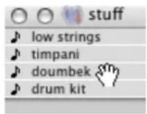
Figure 55-3: To drag and drop clippings, grab their icon. Or, you can select it first and click anywhere on it to grab it.
If the clipping window is in Show by name mode, there is no icon to grab. In this case, Digital Performer lets you click anywhere on a clipping to drag it. Because of this, however, Digital Performer disallows you from dragging over multiple clippings to select them. If you would like to do so, simply switch to one of the show by icon modes.
Track data clippings
Anything that you can put in a track can be stored as a track data clipping. This includes MIDI, audio sequences, conductor data, etc.
Track data clippings appear with a note icon when the clipping window is in small icon display mode. These types of clippings can be dropped anywhere
that you can view track data, including the Track Overview, Track List, Sequence Editor, any MIDI Editor, the Event List and QuickScribe.
To import a track data clipping into a sequence by dragging, you can drop it into the Track List, Track Overview or Sequence Editor. If you drop it into the Track List or onto the track settings panels in the Sequence Editor (on the left side of the window as shown in Figure 38-1 on page 372), doing so creates new tracks with the clipping data inserted at the beginning of the sequence.
Alternately, if you drop the clipping into the Track Overview timeline or the Sequence Editor timeline, the data will be dropped at the cursor's current timeline location. If the cursor is placed over existing tracks, and the tracks in the clipping are compatible with the target tracks (MIDI to MIDI, audio to audio, etc.), then the clipping data will be merged into the existing tracks.
If, instead, you wish to place the clipping data into new tracks at the cursor's timeline location, position the cursor near the dividing line between two tracks in the Sequence Editor or Tracks Overview. You will see a gap appear between the two tracks to indicate that you are inserting new tracks, rather than merging into existing tracks.
Signal routing within a multi-track clipping
If a clipping file was created in Digital Performer version 10 or later, then any signal routing between the tracks within the clipping (using buses) is also saved within the clipping file. If the preference to Create new bus bundles when importing track data clippings is enabled (Figure 7-24 on page 90) when importing the clipping into new tracks, then Digital Performer will remap bus routings within a track data clipping to new bus bundles to preserve the routings within the clipping as well as the bus routings already established in the current document. If this preference is disabled, or if the clipping was created prior to Digital Performer 10.0, then Digital Performer will honor the bus routings that were in effect when the clipping was created, and will not create any new bundles.
Soundbite and audio file clippings
Soundbite clippings, when dragged from a clipping window, become soundbites. They can be dropped anywhere in Digital Performer that soundbites can be dropped. Both Soundbites and audio files show up with a single-waveform icon in the clipping window for mono files or a dual-waveform icon for stereo files.
Plug-in effects clippings
You can select one or more plug-ins for a track in the Mixing Board (they must be instantiated on the same track) then turn them into a clipping (as shown in Figure 70-32 on page 847) by either dragging and dropping them into a clipping window (as explained in "Plug-ins as clippings" on page 847) or by choosing Edit menu> Copy to Clipping Window.
Saving sequences and songs as clippings
You can select a sequence or song in the Chunks window and turn it into a clipping by choosing Edit menu> Copy to Clipping Window.
Selecting clippings
To select a single clipping, click its name. To select several clippings, drag across their names, or shift click each one.
Auditioning clippings
To audition a clipping, double click the clipping. To audition multiple clippings, select them as described above and then double-click one of the highlighted clippings.
If you are auditioning audio clippings and don't here anything, you may have soundbites whose parent audio file has been deleted, or they might not match the current sample rate.
In the case of MIDI data, you may not have a MIDI device connected properly. Digital Performer attempts to play MIDI clippings on the devices that they were originally assigned to when created. Digital Performer tries to find a suitable device if the original device is not available.
If auditioning from the clipping window is not working out, you can always drop the clipping into a track and set up the playback settings exactly the way you want.
Deleting a clipping
To delete a clipping, drag it to the trash, or select it and press the delete key.
Renaming a clipping
To rename a clipping, Option/Alt-click the name of a clipping.
Re-ordering clippings in the Clipping window
You can re-arrange items in the clipping window by grabbing their icon to the left of their name and dragging up or down in the list as desired.
Launching other documents from the clipping window
Double clicking on files and folders in a clipping window to open the folder or open a document in its native application.
Dragging items in from the desktop
A clipping window can contain any item from your computer desktop.
Dragging clipping files in from the desktop
Clippings files (located in one of Digital Performer's clipping folders) can be dragged from the computer desktop to any window in Digital Performer that accepts clippings.
Alias/shortcut clippings
macOS alias or Windows shortcut clippings work just like the original file — with two exceptions: rename and delete operate on the alias/shortcut
and not on the original file. Otherwise, Digital Performer handles the alias/shortcut just like the original file.
Exporting a selection as a clipping file
To export the currently selected audio and/or MIDI data as a clipping, choose File menu > Export > Selection As Clipping File.
CHAPTER 56 Custom Consoles
OVERVIEW
Digital Performer's custom consoles provide a host of control items, including:
■ Sliders
Knobs
- Buttons
■ Menus
Each control item can be used for virtually any musical purpose that involves MIDI data. For example, a control item can:
■ Act as a “virtual” MIDI instrument, generating continuous data which can be sent to MIDI instruments and recorded into tracks
■ Remap data, such as velocities into controllers
■ Modify velocities of notes as you play back
■ Generate system exclusive data to modify synth parameters on the fly
■ Generate controller data to control and shape the sounds in your synthesizers
The sliders, knobs, and buttons can be controlled in real time, while Digital Performer is playing back or recording, to create musical effects. In addition, they animate during playback to reflect what you have recorded.
Note: for standard multitrack mixing of MIDI tracks (volume and pan control), use the Mixing Board (Project menu). It provides a more advanced environment for mixing applications. For details, see Part 7, "Mixing" (page 819).
Custom Console Basics....712
Building a Custom Console....712
Controlling Knobs and Sliders....720
Recording a Knob, Slider, or Button....721
Taking a Snapshot of a Console....723
Animation During Playback....723
Using Controllers Above 63....723
Grouping Control Items....724
Generating Sysex with a Slider or Knob....726
Hints....728

Figure 56-1: A custom console.
CUSTOM CONSOLE BASICS
Custom Console control items serve two functions. First, they monitor MIDI data being played from their target track or MIDI channel, animating in real time to reflect the data's current value. For example, let's say you have a track containing a stream of controller #1 (mod wheel) data, and the controllers increase in value over the span of two measures of music (in the range from zero to 127). A control item assigned to monitor controller #1 in the track will move as the track is played back, reflecting the changes in the values of the controller.
Secondly, control items generate new continuous MIDI controller data in real time when you take control of them, and send the data to either a MIDI device or track. When you take control of a control item, the new data that it generates overrides the data already in the track.
To demonstrate this, let's return to the mod wheel example above. If you play back the track and grab the control item with the mouse half way through the stream of mod wheel data, you will take control of the track with the control item. The mod wheel data remains in the track (assuming that recording is not engaged), but it does not get played as long as you are gripping the control item with the mouse. If you release the control item, it will immediately begin monitoring the existing data in the track again.
In summary, control items monitor continuous data being played back from their target track or MIDI channel. Grabbing a control item generates new data which overrides the data in its target track. During playback (Digital Performer is not recording), the new data does not modify the track; it only temporarily overrides the continuous data in the track. (If recording is engaged, then your new moves replace existing data. More on this later in the chapter.)
BUILDING A CUSTOM CONSOLE
Custom Console controls are created and displayed in custom console windows. You can create as many custom console windows as you like. They save, close, and open like other Digital Performer windows. They are saved with the file in which you create them, although the Load command (File menu) can export them to other projects.
If you would like to create your own customized console, you can open a new, blank custom console. To do so, choose New Console from Project menu > Consoles or any console's window target menu.
Quick Reference
A new, empty console window appears. It has a standard title bar with close, minimize, and zoom buttons, a window target menu, mini-menu and grow box like a standard Digital Performer window. Drag the title bar to move it. Click the close box to close it.

Figure 56-2: A new custom console.
Window target: This displays the current console. If you have more than one console in your project, you can switch between them with this menu, or create a new console. You can also open multiple Console windows from the Project > Consoles menu.
Mini-menu: Use the “Edit Console” item under the mini-menu to toggle Edit mode on or off. A variety of other commands are also available; see “Mini-menu Quick Reference”.
Edit palette: This appears when Edit mode is enabled. To add control items to the console, drag them from the Edit palette to the control item area.
Control Items area: This is the area where you create and position the knobs, sliders, buttons, etc.
Mini-menu Quick Reference
Edit Console: Toggles between two modes in the console. When Edit Mode is on (the item is checked), console items can be moved, resized, deleted, and otherwise graphically manipulated, and the edit palette appears. When Edit mode is off, the Edit palette is hidden and control items cannot be moved; instead, sliders slide, knobs turn, buttons push, and so on.
Set Console Name: Provides a dialog box in which you can change the name that displays in the title bar of the console and in the Window menu.
Duplicate: Makes a copy of selected control items.
Snap to Grid: Toggles whether or not control items snap to an invisible grid in the console when they are moved or resized. When checked, Grid Snap is on. When not checked, Grid Snap is off.
Set Grid Spacing: Determines the resolution of the snap grid when snapping is turned on. The resolution is measured in screen pixels, which are approximately 72 dots per inch (dpi).
Align controls: Lines up selected controls to one another in a configuration that you choose. For example, you can line up the centers of several control items by selecting them and choosing this command.
Set to Zero: Sets the value of the highlighted control items to zero.
Set to Null Point: Sets the value of a highlighted master control item to its null point.
Group: Opens the Grouping dialog box for the highlighted control items. This command allows you to assign control items to a group all at once rather than one at a time.
Ungroup: Removes the highlighted control items from their assigned group.
Control Assignment: Opens the Control Assignment dialog box for the currently selected control item in the console. This dialog contains all of the settings for how the control item behaves.
Set Source: Lets you assign a remote control to one or more selected control items together at one time.
Set Target: Lets you assign one or more control items to a destination together at one time.
Min(imum) Time and Value Change: Lets you control the density of the controller data generated by a control item by increasing or reducing the minimum allowed time and value change between controllers.
Name item: Lets you type in a name for a currently selected control item.
Delete Control: Removes the currently selected control items from the console.
Delete Console: removes the console from the screen and removes its name from the Window menu.
Creating a slider, knob, or button
To create a control item:
1 (Optional) Select the Snap to Grid menu item to turn the snap grid on or off.
This causes the control item to snap to an invisible grid in the console window when you create it, which can be useful for lining up multiple buttons and sliders.
2 Drag the item you would like to insert from the Edit palette to the Control Item area.
3 When you release the mouse, the control Assignment dialog box appears.

Figure 56-3: The Control Assignment window.
4 (Optional) Choose a source data type for the control item.
See “Making the source assignment” on page 716 for more information.
5 Choose the Target data type for the control item.
See "Making the target assignment" on page 715 for more information.
6 (Optional) Set the minimum time and maximum value change.
These two options (on the left) control the density of the data that the control item generates. The lower the values, the more dense the data. Higher values thin out the data. Try to use as high a value as you can while still maintaining the musical effect you wish to achieve. If you use values that are too high, and the data is too thinly generated, it may not sound good.
7 Choose the minimum and maximum values for the control item.
These are the absolute lowest and highest values that the control item can have. For controllers, the maximum range is 0 to 127. For pitch bend, the range is -8192 to +8191.
8 (Optional) Assign the control item to a group.
See “Grouping Control Items” on page 724 for more information.
9 (Optional) Type in a name for the control item.
10 If desired, change the type of item (slider, knob, button) by choosing a different item type from the Type pop-up menu.
11 When you have set all of the parameters as desired, click OK.
The control item appears in the console. Notice that it has a box around it. You can click the handle in the lower left of the box to further reshape or resize the item.

Opening the Control Assignment window
The Control Assignment window is where you make all the settings for a control item. This window automatically appears when you first create the control item. You can revisit the window at any time. To open the Control Assignment window for a control item:
1 Put the Console window into Edit mode (with the Edit Console mini-menu item highlighted as shown in Figure 56-2 on page 712).
2 Double-click the control item.
As a shortcut, you can skip step 1 above and simply double-click right next to the control item (not directly on the control item itself).
Making the target assignment
The target assignment is made in the Control Assignment dialog box when you first create the slider, knob or button as described in “Creating a slider, knob, or button” on page 714. The target can be changed at any time in the Control Assignment window (see “Opening the Control Assignment window” above).
The target assignment consists of two things: the type of MIDI data and the target, which is the place where the data will be sent. To access the target settings, open the Control Assignment window for the control item as described in the previous section.

The target data type is the specific type of MIDI data that the control item will send and monitor. A control item only monitors one track and one data type at a time.
Sliders, knobs, and buttons in Digital Performer can control just about any type of MIDI data, including:
■ Continuous controllers
■ Switch controllers (either as switch controllers or as continuous controllers)
■ System exclusive messages
■ Notes and velocities
For velocities, the slider or knob modifies the velocities of notes in the target track as they play.
The Target is the place where the data will be sent by the slider, knob or button. The target can be:
■ A track
■ A MIDI device
Target track
When the target is a track, the data from the control item is sent to the track, which then records and plays the data. In turn, the control item monitors the material it recorded in the track, animating as it does so. However, the control item only records into that one track in that one sequence; it cannot control another track in another sequence, unless you reassign it.
Target MIDI device
When the target is a MIDI device, the data from the control item is sent to the track in the current sequence which is assigned to that device. This is the most flexible of the target assignments because it doesn't matter what sequence is playing at the time. As long as one of its tracks is assigned to the device, the control item data will be recorded and monitored in the track.
Echo data from source to target
This option, when checked, causes the control item to pass source data directly to the target destination, exactly as it was received. When unchecked, the control item generates the target data type as specified by the settings below this check box.
Making the source assignment
The source assignment is made in the Control Assignment dialog box when you first create the slider, knob or button as described in “Creating a slider, knob, or button” on page 714. The source can be changed at any time in the Control Assignment window (see “Opening the Control Assignment window” on page 715).
What is a source for the slider or knob? It is a device other than the mouse which you can use to control the slider or knob. Normally, you change the value of a slider or knob by dragging it with the mouse. At times, however, it might be useful to move it from an external controller, such as the modulation wheel or data entry slider on your MIDI keyboard controller. To do so, set the Source assignment to match the incoming MIDI channel and data type for the controller you wish to use.
The source assignment consists of two things: a type of MIDI data and the MIDI channel or track from which the data is being generated.

Notice that the slider or knob can be controlled by notes, velocities, pitch bend, controllers, or even mono pressure.
Source MIDI channel
Set the MIDI channel to match the transmit channel of the controller, pitch bend wheel, or whatever you are using.
Source track
Notice that the source can also be a track. Source data in the track then controls the slider. This allows you to create interesting effects. For example, you can assign the source of a slider to be the velocities of notes in track 3. You can then assign the target to be controller number 7 (volume) and assign it to the synth playing back the notes in track three. When you play the track, the slider reads the velocities and sends out a volume controllers to match the velocities, thus enhancing the volume change effect from the velocities.
Only follow source when selected
When this option is checked, the control item will only respond to source data with it is selected. (See "Selecting control items" on page 719.) When this option is unchecked, the control item will follow source data whenever it is received by Digital Performer. This option is useful if you have several control items with the same source that you would like to be able to control one at a time, as needed.
Changing the source or target
To change the source or target assignment, open the Control Assignment window for the control item as explained in “Opening the Control Assignment window” on page 715.
Adding increment/decrement buttons to a slider or knob
To connect a scroll button to a slider:
1 (Optional) Select "Snap to Grid" from the Console window mini-menu to check it.
Doing so causes the button to be lined up with the slider or knob. Otherwise, you may need to manually adjust the position of the button to line it
up with the slider. The button doesn't have to be lined up, however; it will control the slider no matter where you place it.
2 Insert the slider or knob.
To do so, drag a slider (or knob) from the Edit palette to the Control Item area. The Control Assignment dialog appears. Select the desired settings and click OK.
3 Now drag an Increment button from the Edit palette to the Control Item area (or hold option while dragging to create a Decrement button). Drag it directly on top of the slider.
Don't worry about the exact placement of the arrow yet. You can take care of that after you have inserted it. Control the size of the arrow with the size of the box that you drag out. Below, an increment arrow is being inserted by dragging to the right. Notice that the cross-hair was initially clicked on top of the slider.

After a button has been inserted, you can adjust the size and placement by dragging the button and its size handle. Use the Align command in the mini-menu to quickly line things up.
4 Adjust the size and placement of the button as needed.
Use the Align command in the mini-menu to automatically align the button with the slider.
5 To use the button, disable Edit mode and click the increment (or decrement) button.
Adding a value box to a slider, knob, or button
A value box displays the current value of the slider, knob, or button, and it will update continuously as you move the slider or knob.
If you want, you can add a value box to a button. However, buttons can only send up to two values, so a value box might not be useful since it will only display two different values. (On the other hand, you might have a situation in which it would be useful, so that's why we mentioned it.)
To add a value box:
1 (Optional) Select "Snap to Grid" from the Console window mini-menu to check it.
Doing so causes the value box to be lined up with the slider or knob. Otherwise, you may need to manually adjust the position of the value box to line it up with the slider. The value box doesn't have to be lined up, however; it will be connected to the slider no matter where you place it.
2 Drag a slider, knob, or button from the Edit palette to the Control Item area. The Control Assignment dialog appears. Select the desired settings and click OK.
3 Drag a value box from the Edit palette to the Control Item area, on top of the item to which you wish to add the value box. If grid snapping is enabled, click in the corner to line up the value box with the knob or slider.
4 After the value box has been inserted, you can adjust its size and placement.
Using value boxes
You can enter a value into a value box just like any text boxes in Digital Performer, including just dragging up or down on the value box.
Labelling a slider, knob, or button
Often you will want to label the sliders, knobs, and buttons that you create. If you didn't set the name when you first created the control item, set it as follows:
1 Click the border of the control item to select it.
Alternatively, you can Shift-click anywhere on the control item to select it.
2 Choose "Name Item" from the mini-menu.
3 Type in the desired name.
4 Click OK to confirm your choice.
To add a label to the control item:
1 Drag a label from the Edit palette to the Control Item area, on top of the control item you wish to label.
The label appears.
2 If necessary, drag the label to the desired position.
You can do so with grid snapping enabled or disabled.
Changing a label
To change the text of a label:
1 Click the label to select it, or click the border of the control item.
2 Choose "Name Item" from the mini-menu.
3 Type in the new name and click OK.
Note: as a shortcut, you can Option/Alt-click the label.
Creating a button
Buttons send one MIDI message at a time. For example, a button might send a patch change to a synth or a MIDI patcher.
To create a button:
1 Drag a button or text button from the Edit palette to the Control Item area.
2 The Control Assignment dialog box appears. Set the Source and Target items as desired.
See “Making the target assignment” on page 715 and “Making the source assignment” on page 716.
3 Select the type of button you wish it to be.
There are three types of buttons:
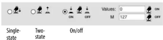
■ Single state button: sends a single message only.
■ Two-state button: toggles between two messages, sending the first when it is pressed and the second when it is released. For example, you might want to create a temporary mute button that mutes the track only while you are holding down the button. If you choose this type of button, you have two values to enter to the right of the option.
■ On/off button: toggles between two messages, sending the first when it is pressed and the second when it is pressed again, and so on. For example, the button might toggle between a volume controller of zero and 127 to mute and unmute a track. If you choose this type of button, you have two values to enter to the right of the option.
4 If you want the button to act like a mute button, click the "M" next to off value button as shown below.
When this setting is enabled, the button sends the current value of its target controller type at the time the button is unmuted, instead of sending a specific maximum value. This makes a button assigned to controller #7 (volume) act just like a real mute button by returning the track to the current volume at the moment it is unmuted.

Figure 56-4: Making a mute button.
5 If desired, choose a group for the button.
Buttons can be grouped, either by a master button or even by a slider or knob.
6 If desired, type in a name for the button.
If it is a text button, the name will be displayed inside the button.
7 Click OK.
Selecting control items
Shift-click anywhere on a control item to select it. You can also use Shift-clicking to select multiple items.
To select a group of items, drag a selection box over them.
To select all the items in the console, choose Select All from the Edit menu, or press command-A.
Cutting, copying, and pasting console controls
Console controls can be cut, copied, and pasted. This greatly facilitates the process of building a custom console. For example, if you are creating a number of items that are similar, make one first and then copy and paste it as many times as needed. Then make the necessary minor adjustments to each copy.
To cut or copy a control item:
1 Choose "Edit console" from the mini-menu.
2 Select the desired items.
Note that you can select more than one at a time. For information about selecting control items, see "Selecting control items" above.
3 Choose Cut or Copy from the Edit menu.
To paste a control item after cutting or copying, choose Paste from the Edit menu.
Aligning control items
There is an Align Controls command in the Console mini-menu to help align selected console controls. To use this command:
1 Make sure "Edit Console" is enabled (via the mini-menu).
2 Select the items to be aligned.
3 Choose Align Controls from the mini-menu.
The Align Controls dialog appears.

4 Choose the desired options.
In this example, we are aligning the centers of the controls left-to-right.
5 Click OK.
Nudging control items
Selected control items can be nudged using the arrow keys. Be sure that the item you want to nudge is selected. (You can nudge several at once, too.) Also make sure that Edit Mode is enabled. Items are nudged one screen pixel each time you press an arrow key, unless the Snap to Grid mini-menu command is checked. If so, the controls are nudged by the amount of the current grid setting.
Moving or removing control items
After you have selected control items as described in the previous section, you can drag them anywhere in the console window. You can also remove them from the console by hitting the delete key, by choosing Erase from the Edit menu, or by choosing Delete control in the console mini-menu.
Duplicating a control item
To duplicate a control item:
1 Select the control item.
See "Selecting control items" on page 719.
2 Choose "Duplicate" from the Console mini-menu.
Changing the parameters of a control item
To change the source, target, grouping, and other parameters for a control item, open the Control Assignment dialog as described in “Opening the Control Assignment window” on page 715.
Moving or resizing a control item
To move or resize a control item, you need to be in edit mode. To enter edit mode, click "Edit Console" under the mini-menu so that it becomes checked. When you are in edit mode, you can only edit control items. You cannot use them, i.e. you cannot slide a slider, turn a knob, press a button, etc. To use the control items again, unhighlight the edit mode button.
As a shortcut, you can enter edit mode temporarily by holding down the Command/Ctrl key (instead of enabling “Edit Console”) as you click the control item. Doing so allows you to move it or resize it without enabling “Edit Console” under the mini-menu.
CONTROLLING KNOBS AND SLIDERS
The following sections explain how to control sliders and knobs.
Controlling a slider or knob with the mouse
Try moving the slider with the following actions to familiarize yourself with them.

flowchart
graph TD
A["Start"] --> B{Click the +/- buttons to move the slider by one.}
B --> C["Drag the handles to change the slider's value smoothly."]
C --> D{Click anywhere on the bar to snap the slider to that position.}
D --> E["Press the +/- buttons to move the slider smoothly."]
E --> F["Click the slider value and type a new value"]
F --> G["68"]
To turn a knob, simply click on it and drag horizontally or vertically.
Controlling a knob or slider with a mod or pitch bend wheel
After you have made the source assignment as described in “Making the source assignment” on page 716, click the slider or knob name to highlight it and move the mod wheel. You will see the slider respond as you move the wheel.
If the “Only follow source when selected” option is unchecked (in the Control Assignment window for the knob or slider), it is not necessary to select the control item. See “Only follow source when selected” on page 716.
When a slider or knob is being controlled externally, data from the external source is exclusive to the slider; that is, the data is used solely to control the slider and will not be accidentally recorded into another track.
Remapping data on the fly
External control is a very powerful feature because it allows you to reassign continuous data in real time as you move the controller. For example, a volume slider that is being controlled by a mod wheel is actually receiving controller #1 data from the wheel and then converting it into controller #7 data on-the-fly.
Digital Performer also allows you to control sliders with several types of data that you might not consider at first: notes, velocities, and aftertouch.
Moving a slider or knob during playback
To move the slider during playback, simply press the play button and move the slider with the mouse or mod wheel.
Controlling a slider or knob with notes
MIDI notes are numbered from 0 to 127. C3 is note number 60, for example. Note numbers correspond exactly to controller numbers, so pressing a note on your keyboard will set the slider to its corresponding value. This is useful for creating sudden, precise changes in controller value rather than smooth changes. Keep in mind while you do this that most keyboards do not have 127 keys and therefore will not allow you to span the entire zero to 127 range of the slider.
Controlling a slider or knob with velocity and aftertouch
Note velocities can also be used to control the slider, since they also span the range from zero to 127. The harder you strike a key, the higher (or lower) the slider will go. This might be useful for setting up a slider to send a controller that, in turn, affects a synth in a certain way: as you strike the key harder, the musical effect will become stronger (or weaker).
The same applies to aftertouch data. The harder you press on the key, the higher (or lower) the control item will go.
RECORDING A KNOB, SLIDER, OR BUTTON
After a control item's target and source parameters have been set up, you can record data generated by it into its target track. Recording with control items is specially designed so that the data from the control item will not erase data that already exists in the track. Instead, data generated by a knob, slider, or button is merged with existing data. For example, you can record some mod wheel data from the control item without erasing any of the notes in the track.
On the other hand, data from the control item replaces any existing data of the same type. If a track already contains mod wheel data from measure 1 to measure 10, and you record briefly with the slider in measure 5, the new data recorded from the slider will replace the existing mod wheel data in measure 5.
With this in mind, sliders, knobs and buttons can be recorded in one of the following ways:
- You can record a single “snapshot” of the current setting of all the sliders and buttons in a console. To do so, set the Main Counter to the desired location, set up the console the way you wish, and then choose “Take Automation Snapshot” from the Region menu. You can also take a snap during playback or while recording, using the Region menu or by pressing the keyboard shortcut (Control/Win-'). For more information, see “Taking a Snapshot of a Console” on page 723.
- You can record during playback, with the slider or knob recording continuously, even when you are not moving the slider, so that it continually replaces its own data type in the track.
Preparing to record
There are two ways to record knob or slider data without modifying or erasing any existing data:
■ Record-enable the target track and place Digital Performer in overdub record mode.
OR
■ Leave all tracks unarmed for recording (to prevent accidental erasure of existing material) and then make sure that the console window is the front-most window when you begin recording.
When recording console controls, a track does not have to be record-enabled — as long as the console window is the front-most window. When the console window is active, Digital Performer allows you to press the record button, even with no tracks armed for recording.
Recording during playback
After making the preparations just described, you are ready to record the control item. Press the Record button in the Control Panel and move the control item. When you move the control item, it generates data that gets recorded in the track, replacing any existing data of the same kind at the same location. When you release the control item, recording will stop and the control item will return to monitoring the track. Other data in the track will be preserved.
Punch-in recording using an external control
Moving the control item from an external control while punching in works much the same way: to punch in, the control item waits to receive an event from its external controller. When it does, it punches in. Punch out, however, is done automatically by Digital Performer and is determined by the amount of time after the last event was received from the controller.
Auto Punch Out Delay
Since controllers send data with different degrees of sensitivity, you may find that punch out occurs too frequently. To avoid stuttering punch out, you can lengthen the delay before Digital Performer punches out with the Auto Punch Out Delay option in the Automation Setup window (Setup menu). The Auto Punch Out Delay option allows you to determine the punch out delay in milliseconds.
Summary
Here are several situations and a description of what control items will do in each case:
Digital Performer is not playing or recording:
When the current location of the sequence is changed with the Main Counter, all control items jump to the value of their assigned parameter on their assigned track. They may then be moved; as they move they send out MIDI data of the assigned data type on the channels of their assigned tracks.
Digital Performer is playing back: As Digital Performer plays, the control items animate to reflect the values of their target data type from their target. A control item may be grabbed and moved independently, either by simply grabbing the handle or by external control; it then transmits MIDI data that takes the place of out-going data from its source track. The data it generates does not get recorded. When the control item is released, it returns to tracking the target track.
Digital Performer is recording: When Digital Performer is recording, the control item simply monitors its target, just like playback. When you move it with the mouse, it records your movement. Data in the target track is replaced by
data generated by the control item. (Only data of the same type is replaced). When the control item handle is released, the control item starts tracking the target track again.
TAKING A SNAPSHOT OF A CONSOLE
After you have created your custom console, you can take a snapshot of it. A snapshot captures all of the current slider and knob settings. The snapshot is placed into the tracks of the currently play-enabled sequence.
If you would like to record the snapshot, the target assignment of the sliders and knobs must be either a track or a device (instead of a MIDI channel).
To take a snapshot of the current position of the sliders, knobs, and buttons in a console:
1 Set the main counter to the desired location at which you wish to record the snapshot.
You can also take the snapshot during playback or recording.
2 Set up the sliders, knobs and other control items the way you would like them to be in the snapshot.
3 Select the control items in the console that you want to include in the snapshot.
See "Selecting control items" on page 719.
4 Choose "Take Automation Snapshot" from the Region menu, or press its keyboard shortcut (Control/Win-').
When you take a snapshot, each control item generates a MIDI event at that instant. The value of the event is determined by the control item's position at the time the snapshot is taken. The event is inserted into the control item's target track. If you have taken the snapshot of many sliders, knobs, etc., each item places its data into its own target track.
Editing a snapshot
After data has been inserted into one or more tracks by taking a snapshot, the data can be edited in the standard fashion in the tracks. For example, if you wanted to remove the snapshot, select the data in the tracks window and delete it.
Retaking a snapshot
You can retake a snapshot by first placing Digital Performer's playback head (the wiper) on the same tick at which the snapshot was first recorded, then taking a new snapshot.
ANIMATION DURING PLAYBACK
Unless the control item is being dragged, it monitors its target track, animating during playback to reflect MIDI data that it has recorded into the track. In general, the control item always reflects the current value of its target data type, even when cueing the sequence to a different playback location.
USING CONTROLLERS ABOVE 63
Only controllers 0 to 63 are considered to be “continuous” MIDI controllers — ones that can express any value between 0 and 127. Controllers 64 to 120 are defined by the MIDI specification as “switch” controllers — ones that are either on or off. Controllers 121 to 127 are reserved for special purposes.
Some MIDI hardware, however, treats controllers 64 to 120 as continuous controllers. Digital Performer's control items can generate any controller from 0 to 120 as continuous data, providing you with maximum flexibility with MIDI devices that treat controllers 64 to 120 as continuous controllers.
GROUPING CONTROL ITEMS
Digital Performer's custom consoles provide the ability to group control items together and control them from a master control item. Grouping allows you to control an entire bank of controls at the same time from one control item. Up to 32 control items can be assigned to a single group, and Digital Performer allows up to 26 groups, each identified by a letter from A to Z. Any control item can be a master control item or a grouped control item.
In addition, a master control item that controls a group can, in turn, be a member of another group controlled by another master. This allows you to create sub-groups of control items, and sub-groups within sub-groups. There is no limit to the number of layers you can create.
Master and slave control items
Each control item in the group can have its own, customized relation to the group's master control item. Grouping provides three ways in which a control item (slave) responds to its group master: the grouped control item can match, offset, or scale values received from the master.
When matching the master, the slave simply goes to the same value as the master. For example, if the master control item is set to 79, the slave goes to 79 as well.
When offsetting the master, the slave can start at a different value than the master. When the master moves, the slave moves by the same amount, or by a percentage of the amount. For example, let's say that the master is at 0, the slave is at 20, and the slave is offsetting by 100%. If you move the master to 50, the slave will move to 70. If the slave is offsetting by 50%, it will only move to 45, which is 20 plus half of 50 (25).
When scaling the master, the slave can start at a different value than the master. When the master moves, the slave moves by a percentage of the distance that the master moves in its relation to the end of the control item. For example, lets say that the master is at 0, the slave is at 64, and the slave is scaling by 100%. When the master moves to 64, which is half way to the top, the slave moves to 96, which is halfway of its distance to the top. If the master goes to 96, which is 3/4ths of its distance to the top, the slave goes to 112, which is 3/4ths of its distance to the top. By the time the master has reached 127, so has the slave.
Slaves can be offset or scaled by a percentage between 0 and 999%.
Polarity
In addition to matching, offsetting, and scaling, a slave can react positively or negatively to its master. Positive polarity causes the control item to move in the same direction as its master. Negative polarity causes the control item to move in the opposite direction from its master.
Negative polarity is extremely useful for many musical effects, such as cross-fading or panning. You can bring the volume of one track up at the same time as you bring the volume of another track down.
Null points
In the grouping offset and scaling examples above, you may have noticed that an important part of how masters and slaves work is their initial values. In Digital Performer, the master's initial value is called the null point and the slave's initial value is called its reference value.
A master's null point is the value of the master slider on which changes to slaves are based. It is indicated on a slider as a bold hash mark behind the slider bar.
The slave's reference value is its value when the master is at its null point. Whenever you would like to see the reference value of a slave, move its master to its null point.

The slave responds to changes in the master slider's value, which are measured from the master slider's null point, and it moves from its reference point based on those changes. As the master moves from its null point, the slave moves from its reference value.
Digital Performer's null point is similar to the null point on most recording studio mixing consoles: it is a base value from which slaved sliders are measured.
Hardware mixers usually have a fixed null point somewhere near the middle of the slider's range. The null point of Digital Performer's sliders, however, can be set to any value on the slider, from zero to 127 (or -8192 to 8191). This provides an added level of flexibility when achieving the musical effects that you want.
Moving slaves independently of their master
Slaves always follow their master. However, a slave is not “locked” by the master; it can be moved independently at any time, regardless of the master’s current value (position). When you move a slave, you are changing its reference point with respect to the master. In addition, its relation to the master is temporarily severed. The only way to reestablish the connection is to move the master, or reset the master to its current value.
If you move both a master and a slave at the same time from the same external source, you will sever the master/slave connection between them and the slave will track the external source as if it was not connected to the master.
Assigning a control item to a group
To assign a control item to a group:
1 Select one or more control items.
2 Choose Group from the console window mini-menu.
The Grouping dialog box will appear.
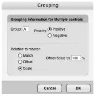
3 Type the group letter to which you want to assign the control item.
The only restriction here is that a control item cannot be the member of a group if it is already the master of that group. Up to 32 control items can be included in one group.
4 Select the polarity.
5 Choose whether to match, offset, or scale from the master.
If you want the grouped control items to reach their highest and lowest value at the same time as the master, choose scale at 100%, which is perhaps the most intuitive way to group control items.
6 Click OK to confirm your choice or Cancel to withdraw it.
Assigning a master control item
To assign a master control item:
1 Select the control item.
2 Choose Control Assignment from the mini-menu.
3 Type a letter in the Group text box.
You can enter any single letter. The only restriction is that the control item cannot be a master of its own group.
4 Choose the Master option.
5 Click OK.
Setting a master slider's null point
To change the null point of a master slider:
1 Option/Alt-click anywhere on the slider.
The null point, which is indicated by a bold hash mark, will snap to the location, and you can drag it freely from there.
The null point can also be changed more precisely as follows:
1 Select the master slider.
2 Choose Control Assignment from the console mini-menu.
3 Make sure the Master radio button option is selected.
4 Type in the desired null point in the box provided.
5 Click OK to confirm your choice or cancel to withdraw the command.
Setting a slave's reference value
To change the reference value of a slave, move the master back to its null point, and then move the slave to the desired value. It is not mandatory to move the master to its null point beforehand, but if you do not, the value you are setting is the actual reference value and does not reflect the current difference between the master and its null point. As soon as you move the master again, reestablishing the master/slave connection, the slave will pop to its new relative position, often causing an unexpected result.
Moving a master to its null point
To move a master to its null point, either drag the master's handle to the bold hash mark, or highlight the slider and choose Set to Null Point from the Console mini-menu.
Sending multiple MIDI messages at once with grouped buttons
You can group buttons to a master button to send various messages to various destinations all at once. Just assign each button to the same group. Make sure each button is of the same type. Then create a master button that is also the same type. When you press the master button, the slaved buttons will be pressed and released at the same time.
Please note: if you group buttons, the slaved buttons do not animate when you click the master button. They do, however, transmit data.
GENERATING SYSEX WITH A SLIDER OR KNOB
Digital Performer allows you to generate system exclusive data from a slider or knob. The slider generates a continuous stream of messages, each containing a range of bytes (up to four) that are changed incrementally by the slider or knob.
Doing so allows you to control device-specific parameters of MIDI hardware in ways that can not be achieved with continuous controller data.
Please note! This section is not for the technically faint of heart. You should have a firm knowledge of MIDI be already familiar with your hardware's MIDI implementation.
Before you begin this procedure, here's what you need to know about the SysEx message:
■ The message itself, or how to dump it into Digital Performer
■ Whether or not the message contains a checksum, and if so, how many bytes the checksum consists of
■ What the data bit format is (7-bit or 4-bit nibble)
■ Which comes first, the LSB or the MSB
■ The specific bytes within the message that will be the variable bytes controlled by the control item (up to 4 bytes)
To set up a control item that generates SysEx, you must first enter the SysEx data into Digital Performer, and you have two choices for how you can do so. You can:
TYPE IT IN BY HAND
TYPE IN A REQUEST MESSAGE AND RECORD IT FROM THE SYNTH
To set up a SysEx slider or knob:
1 Create the slider or knob.
If the SysEx message you'd like to control was recorded as a bulk dump into a device, be sure to assign the target to the device.
2 Select it and choose Control Assignment from the console mini-menu.
3 Choose system exclusive from the Target data type menu.
4 Click the Set Sysex button.
The Assign Slider Sysex window appears.

If you want to type in the SysEx message, type the message into the SysEx editor. For more information about how to use this editor, see chapter 54, "System Exclusive" (page 697).
If you would like to enter a bulk dump request message, click Transmit. Digital Performer's standard SysEx editor window appears, into which you can type in the bulk dump message. See the System Exclusive chapter if you need more information.
Choosing the variable data bytes
After you have the SysEx message you want in the SysEx editor display, you can now select which data bytes are to be the variables that will be controlled by the slider.
To select the variable data bytes:
1 Choose replacement mode for the edit cursor so that you can highlight the desired bytes.
2 Select the desired data bytes.
You can select up to four bytes.
3 After the bytes are selected, click the Value button.
Notice that the bytes now turn into "VV."
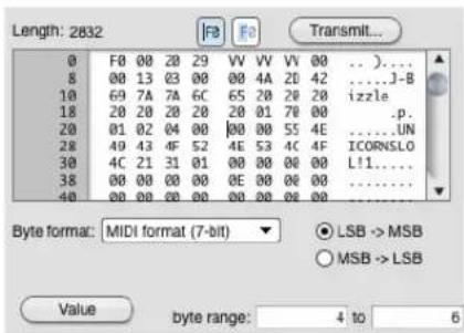
Note: if the SysEx message is a device bulk dump, several sliders can edit the same bulk dump message.
To see the values of the bytes being covered up by the slider, use the arrow keys to scroll the insertion cursor through the bytes. When it passes through the slider, the slider disappears for a few seconds.
Setting the checksum
If the synth requires a checksum, Digital Performer must generate the proper checksum as well, and it needs to know an initial value to do so.
To set the initial checksum value:
1 Click the Use Checksum check box.
2 Select either the Straight sum or Sum to zero option.
3 Type in the number of bytes for the checksum value.
4 Identify the first data byte that is checksummed.
To do so, type in the byte number next to the Checksum button, or place the cursor at the first byte of checksummed data (normally the first byte immediately after the SysEx header) and click the Checksum button.
Setting the bit formats
Select the appropriate bit format from the menu and select either LSB->MSB or MSB->LSB. You are done! Click OK. The slider will now generate the SysEx message. If the synth does not respond, verify the checksum values.
Monitoring a SysEx slider during playback
Sysex sliders cannot monitor the data they generate. This is due to the amount of data processing that would be required in real time.
Here is a work-around for this problem:
1 Create two sliders.
2 Make one the master and the other a slave.
3 Make the Master slider generate an unused controller and assign its target to a track.
4 Make the slaved slider read that unused controller from the same track as its source.
5 Then make the slaved slider generate the SysEx data.
In this scenario, you move the master slider. It generates controller data at the same time that it is controlling the SysEx slider, so that the SysEx slider matches its movement. On playback, the SysEx slider monitors the controller data and generates the SysEx. Thus, the SysEx data never gets recorded in the track; only the controller data does. But the controller data and SysEx data match because the were slaved when originally recorded. The end result is that the SysEx slider animates and plays back exactly as it was record.
HINTS
Control items can serve many purposes. Some suggestions are discussed below.
Remapping continuous data
Control items can be used for remapping continuous controller data in real time. For example, you may have a synth module that responds to controller #10 (MIDI Pan), but you
may not have any keyboards that can send this particular controller. A control item can solve this problem by remapping a controller that your keyboard does send into controller #10. To do so, assign the source of a control item to be a controller that your keyboard can transmit, such as controller #1 (mod wheel). Set the control item's target to be the Device or track that sends to the synth module. Set the target data type to controller #10. Now, when you send controller #1 data from your keyboard by moving the mod wheel, you will be controlling the Pan settings on your synth module.
Control Items also offer a way to reassign continuous data in real time instead of using the Reassign Continuous data command. For example, you may have a track of controller #3 continuous data that you wish to change to controller #7. You can set up the source of a control item to be the track containing controller #3. In turn, you can assign the target data type to be controller #7, and assign the control item to send the data to a different target track. When you press record, the control item will read in the controller #3's and generate controller #7's, which in turn will be recorded into the target track.
Improving console animation
Digital Performer's first priority is to keep up with the flow of MIDI and audio data. If it encounters a great deal of data, it selectively ignores its graphic display until the processor load decreases. This may affect the animation of control items, and they may not move smoothly when lots of data is being played—especially if there are many control items on the screen. This is Digital Performer's way of keeping up and does not necessarily mean that data is being transmitted inaccurately.
Digital Performer gives the currently active window highest priority when animating control items. Therefore, whenever you want to watch control items while Digital Performer is playing back, make sure their window is active. To activate the window, simply click anywhere on the window.
If the control items you want to watch are in different consoles, you may want to create another single console that contains all of the control items you wish to monitor during playback. You can then make it the active window, and all of the control items in it will animate as smoothly as possible. You will find that as long as the console is active, Digital Performer does a pretty good job of animating control items accurately.
Another way to improve control item animation is to close as many consoles as possible.
Loading control Items and consoles from another project
Consoles from one Digital Performer project can be imported into any other Digital Performer file using the Load command (File menu). This means you can set up control items the way you like them once, and they'll be available for importing into any of your files.
The Consoles that you create in a file are automatically saved as part of that file. The Load dialog box, however, enables you to extract them from an unopened file, then load them into the file in which you are working.
To load Consoles into an open file:
1 Choose Load from the File menu.
The standard open dialog box appears.
2 Click the file containing the assignments you wish to load, then click Open.
Alternatively, you can double-click the file name. Digital Performer's Load dialog box appears, displaying the file name at top.
3 Choose the Consoles option.
4 Optional: If you wish to load any Chunks from the selected file, choose the Load Chunks option.
If you wish to load more than one Chunk, you can drag to select contiguous Chunks and Shift-click to select discontinuous Chunks. Deselecting this option loads only the file's Control Items.
5 Click OK to confirm your choices or Cancel to withdraw the Load command.
Clicking OK causes the selected file's Consoles, as well as any selected Chunks, to be loaded into the open file. The imported consoles appear in the Window menu.
Sending note-ons and note-offs
When you program a button or slider to generate notes as shown below by the "Send" menu, you have three possibilities:
SEND NOTES (BOTH NOTE-ONS AND NOTE-OFFS)
SEND NOTE-ONS ONLY
SEND NOTE-OFFS ONLY
For option 1, leave both check boxes unchecked. In this case, the slider, knob, or button will send a note-on when you click it, and it will send a note off when you release it or move it to another note.
For options 2 and 3, click the appropriate check box. In this case, the slider, knob, or button sends only a note on or a note off when you click it or move it.
Please note: note-ons and note-offs by themselves do not constitute an entire note. Therefore, they cannot be recorded into a track.
Creating a mute button
To create a mute button, create a button as described in the section “Creating a button” on page 718. For the maximum value, click the “unmute button” as shown in Figure 56-4 on page 719.
Automating a fader group with a master control
Master console controls can control their slaves while monitoring a target track. This means you can automate the movement of many slave controls at once by recording only the data of their master control. For example, you can automate a master fade-out at the end of a sequence by slaving multiple sliders (one for each track or device in your sequence) to a master slider and then recording the master slider. When you play back the result, the master slider monitors the data you recorded in its target track and simultaneously drives the volume sliders for all other tracks. To accomplish this, make sure that the master slider target assignment is a track (or a device which is assigned to a track).
Remember that the master slider's track must be play-enabled for this to work. (It can't be muted.) As a result, you might consider assigning the master slider's track to a MIDI channel that you don't use. Also, since the target data type for the master slider doesn't matter (as long as it is some type of continuous controller), you might consider using a target data type for the master slider that is unlikely to affect anything else (like controller number 45).
Part 6
Arranging
CHAPTER 57 Conductor Track
OVERVIEW
The Conductor track is a special track containing markers, meter, tempo and key change information. Every sequence and song has a Conductor track; it cannot be deleted. You may use the commands from the Edit menu in the Conductor track to Cut, Paste, Repeat, Shift, and otherwise edit tempo, meter, and key maps, as well as markers. In addition, the Conductor track can be used to directly insert simple tempo, meter, and key changes, as well as to 'record' a tempo map entered in real time using Tap tempo synchronization.
The Conductor Track can be edited in the Event List and the MIDI Editor. It can also be edited in the Sequence Editor in the same manner as in the MIDI Editor. The examples in this chapter refer to the Conductor track's Event List; see “Editing in the Conductor Track” on page 434 for more information.
Conductor track basics....733
Opening the Conductor track....733
Types of Conductor track events....733
Working with the Conductor track event list .....737
Working with the Conductor track Editor ....737
Editing in the Conductor Track....737
CONDUCTOR TRACK BASICS
The Conductor track automatically appears in the Tracks window for each sequence. The Conductor track cannot be deleted or renamed; it can be moved and given comments like a standard track. The Conductor track has a record-enable button for use with Tap tempo synchronization, described in “Receive Sync” on page 977. The Conductor track cannot be looped.
OPENING THE CONDUCTOR TRACK
The Conductor track Event List and MIDI Editor can be opened in the same fashion as for regular tracks. See “Opening edit windows” on page 341.
A song's Conductor track can be opened by choosing Edit Conductor Track from the Song window mini-menu.
TYPES OF CONDUCTOR TRACK EVENTS
The Conductor track contains the following types of events:
■ Tempo changes
■ Meter changes
■ Key changes
■ Markers
- Click changes
■ Streamers
■ Punches
■ Flutters
These events are not MIDI data; instead, they control or conduct your music's performance during playback. These events can, however, be edited like standard MIDI events, either with the commands on the edit menu or directly in the Event List or MIDI Editor. Markers, click changes and film cue events may be edited in the Conductor Track with edit menu commands such as Cut, Copy and Paste.
The following sections describe each type of event in some detail; for more information on the Change Key, Change Meter, and Change Tempo commands, the Markers window, or film cue events, see their respective chapters.
Key changes
0|1|000 Eb Major
Key change events display the name of the key. User-defined key signatures are displayed as 'Custom'. See chapter 60, "Change Key" (page 755) for a full description of key signatures in Digital Performer.
Meter changes
0|1|000 4/4 click
Meter change events display the time signature (the number of beats per measure, over the duration value which gets the beat) and the click value, (the duration value between metronome clicks). See chapter 59, “Change Meter” (page 749) for more information about these values. Moving meter change events, or inserting them using the Insert button, can cause partial measures. See “Meter changes and partial measures” on page 738 before attempting to move or insert a meter change.
Tempo changes
0|1|003 ♪ = 138.91
Tempo change events display the duration value for the tempo marking, i.e. the note value of the basic beat, and the tempo value itself, as a certain number of beats per minute. Tempo changes can appear as a single event, indicating an abrupt change in tempo, or as a series of events, approximating a smooth increase or decrease in tempo. In this regard they resemble continuous controller data as shown in Figure 39-26 on page 435. For more information on tempo events, see chapter 58, “Change Tempo” (page 741).
Tempo changes can be inserted graphically in the MIDI Editor with the Pencil tool. See “Inserting continuous data in Points or Bars mode” on page 427.
For information on recording a tempo map in real time, see “Tap Tempo” on page 983. Recording in Tap Tempo creates normal tempo events.
See “Editing in the Conductor Track” on page 434 for information on editing tempo changes graphically.
Viewing and typing in frame click tempos
If you write music for film, you might be accustomed to expressing tempos in frame-clicks as well as beats per minute. In Digital Performer, you can type in tempos using either format. You can also display tempos throughout the program, including the Change Tempo dialog, in frame click tempos (e.g. 12-6 or 13/4). For further information about working with frame click tempos, see “Displaying and typing in frame-click tempos” on page 216.
Markers
23|2|078 Guns fire
Markers are visible in all Event List windows, but in the Conductor track, they can be edited with Edit menu commands such as Cut, Copy and Paste. To add a new marker, use the Markers window New Marker mini-menu command.
Click Changes
You can insert click change events in the Conductor track. There are three types of click change events: beat click, tacet click, and pattern click. Together, these click change events give you complete flexibility in programming even the most elaborate click tracks. For example, conductors of film cues can customize the click for each cue in ways that are commonly used on sound stages when recording music for films.
Beat click
3121000 click J
A beat click event creates clicks on an even subdivision of the current beat. They are identical to the beat click that is part of a meter change event, except that they are independent of any meter change events. For example, you could insert a meter change event that clicks every quarter note, but then insert a beat click event a few measures later that clicks every eighth note.
Changing the beat sub-division of the click in this manner can be useful in a wide variety of situations. For example, clicking on quarter note downbeats might work at a medium tempo, but if the tempo then slows down due to a tempo change, then switching to eighth note clicks might work better.
Beat click events allow you to program any click pattern you wish by inserting a new beat click event whenever you wish to change the click.
Tacet dick
3121000 click Tacet
A tacet click event silences the click until the next (non-tacet) click event in the Conductor track. For example, you might create a countoff in which the last two clicks before the downbeat are silent. Or you may want to create a period of audible click silence in which you then program visual elements in the Conductor track (punches, flutters or streamers) during the silence in order to provide a visual timing reference.
Pattern click
3|2|000 click Pattern 2 2 1 1 1 1 / 8
A pattern click is a customized click pattern that you program. Pattern clicks use an editable text code field for programming the pattern. You can easily program and audition different patterns in the Countoff or Click Defaults preferences windows (see “Click Preferences” on page 256 or "Click Defaults" on page 258), where you can choose Pattern for the click style and then type in different text codes and listen to the audition of the click to hear what they create. The syntax is as follows:
What you type What it means
1111/4 Four quarter notes
2 2 1 1 1 1 / 8 Two quarter notes followed by four 8th notes
3 3 1 1 1 3 / 8d Two dotted eighths, three 16th notes, then another dotted eighth
Somewhere in the string there is usually a number followed by a slash followed by a note type indicator, such as the “1 / 4” in the first example, above. The note type indicator must be one of the following:
Indicator Note type
| 1 | W | h | o |
| 2 | H | a | 1 |
| 2t Half note triplet | |||
| 2d Dotted half note | |||
| 4 | Q | u | a |
| 4t Quarter note triplet | |||
| 4d Dotted quarter note | |||
| 8 | E | i | g |
| 8t Eighth note triplet | |||
| 8d Dotted eighth note | |||
| 16 16th note | |||
| 16t 16th note triplet | |||
| 16d Dotted 16th note | |||
| 32 32nd note | |||
| 32t 32nd note triplet | |||
| 32d Dotted 32nd note | |||
The number before the slash determines what numeric value is associated with the given note type indicator. So, “2 / 4” means “everywhere a 2 appears in this string, interpret that 2 as a quarter note.” If 2 means a quarter note, then 4 (twice as big as 2) means half note, and 1 (half as big as 2) means 8th note.
Often the slash will appear at the end of the string, but it can appear anywhere in the string. For example, the string “3 / 4 3 3 1 1 1” means that 3 equals a quarter note, making the pattern three quarter notes followed by three eighth note triplets.
If you don't use the slash anywhere in the string, then the number 1 is assumed to mean an 8th note, and all other numbers a multiple of 8th notes. Therefore, the string “1 1 1 1”, with no slashes anywhere, means four 8th notes and the string
“2 2 2 2”, with no slashes anywhere, means four quarter notes.
You can use any character you like to separate the numbers in the pattern code string. Spaces work well because they help keep the expression simple and clear. But you can also use the plus or period characters, which are handy in the number keypad, or any other non-digit. The parser just looks for the next digit, slash, or non-digit, and understands that digits right next to each other make up a single multi-digit number.
So, if you want to be obscure, you could type:
2 5 6 + 2 5 6* 2 5 6 @ 2 5 6 / = = = = = 4
The above expression would mean four quarter notes, because the computer sees:
As a practical example, you could use the plus or the period key as a separator, making it quick and easy to type in the expression using just the numeric keypad.
Accenting a click
To accent a click in a pattern click, highlight the number you want to accent in the pattern code text and type Command/Ctrl-B. That makes it bold and red. Bold and red clicks are accented, plain black ones are not. Select an accented click and type Command/Ctrl-B again to remove the accent.
Saving custom click patterns
When you access the click type menu on a click change event, there are additional items at the bottom of the menu that let you create and save click patterns by name using the Save Pattern menu command (Figure 57-1). See “Saving a customized click” on page 258.
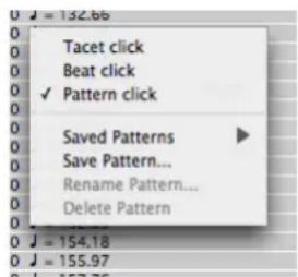
Figure 57-1: Creating and saving custom click patterns.
Streamers

A streamer event triggers a streamer independently from a marker. The streamer event shows the streamer icon; click it to change the streamer color. Click the streamer length to choose from among several industry standard lengths. Click the punch size to change it. Click the streamer display destination on the far right to change it. For further information, see “Streamers, Punches and Flutters” on page 787.
Punches
6:08:29:17 ○ Big -> qt, 1m1
A punch event triggers a punch independently from a marker. Click the punch icon to change its color. Click the punch size to change it. Click the punch display destination on the far right to change it. For further information, see “Streamers, Punches and Flutters” on page 787.
Flutters
6:08:48:04 ○○○ Medium -> qt, 1m1
A flutter event triggers a flutter independently from a marker. Click the flutter icon to change its color. Control/Win-click the flutter icon to change the number of punches in the flutter. Option/Alt-click to change the anchor punch, which corresponds to the exact frame location of the flutter event. Click the flutter size to change it. Click the flutter display destination on the far right to change it. For further information, see "Streamers, Punches and Flutters" on page 787.
WORKING WITH THE CONDUCTOR TRACK EVENT LIST
The Conductor Track Event List operates just like the Event List for MIDI and audio tracks, as explained in chapter 40, "Event List" (page 437). For example, to insert a Conductor track event, you can choose it from the Insert menu as shown below:
![Event List: Conductor Event List Conductor ✓ Key Change Meter Change Tempo Change Click Change Streamer Punch Flutter 11[1]320 = 48.21 13[1]338 = 49.06 13[1]356 = $0.75 13[1]373 = $1.59 13[1]391 = 59.21 13[1]427 = 60.05 13[1]462 = 60.90 13[1]462 = 61.74](/content/2026/05/834832/images/93e88b688255512bd9f93acee6aeaf882619978031c54feaf99f9801dd4c4391.jpg)
Figure 57-2: Inserting Conductor track events in the Event List.
WORKING WITH THE CONDUCTOR TRACK EDITOR
In general, the Conductor Track Editor operates like the MIDI and audio track Graphic Editor as explained in chapter 39, “MIDI Editor” (page 411). However, there are a few notable differences as explained in “Editing in the Conductor Track” on page 434.
EDITING IN THE CONDUCTOR TRACK
The Edit commands Cut, Copy, Paste, Erase, Repeat, Merge, Snip, Splice, and Shift all function on the events in the Conductor track. You can use them to move tempo and meter changes together with other tracks in a sequence, shift tempo maps for precise alignment with synchronized video or audio, or to repeat tempo, meter, and key changes in looped sections. You can insert and edit tempos in the Conductor track without stopping playback.
Be sure to learn how Digital Performer's Smart Selections feature affects Conductor Track editing by reading “Barlines are preserved in the Conductor track” on page 559.
To use the Edit commands on the Conductor track of a sequence:
1 Highlight the Conductor track name in the Tracks window or Sequence Editor and make a time range selection in the Conductor track,
OR
2 Open the Event List or Graphic Editor for the Conductor track and highlight the desired events.
3 Select the desired command from the Edit menu.
To use the Edit commands on the Conductor track of a song:
1 Open the Song window.
Do so by double-clicking the Song name in the Chunks window.
2 Choose Edit Conductor track from the Song window mini-menu.
The edit window for the song's Conductor track will appear.
3 Highlight the events you wish to edit.
4 Select the desired command from the Edit window.
The Edit menu commands affect events in the Conductor track in the same way as normal MIDI data. See chapter 45, “Selecting” (page 547) and chapter 34, “Editing Basics” (page 325) for more on how to select regions and use these commands.
When a region is cut or copied from the Conductor track, meter and tempo events representing the current meter and tempo values are automatically inserted at the beginning of the region in the clipboard. This guarantees that the region will keep its original meter and tempo when pasted elsewhere in the sequence or song. These automatically created meter and tempo change events may be edited normally after the region is pasted back into the Conductor track.
Note that editing meter changes can cause partial measures. See “Meter changes and partial measures” on page 738.
Using the View Filter with the Conductor track
Use the View Filter to effectively edit events in the Conductor track. The View Filter affects the Conductor track the same way as it does for regular tracks. See “View Filter” on page 328.
The View Filter is important when editing the Conductor track because it is common to want to edit just one element, e.g. tempo changes, without affecting the other events in the track.
Meter changes and partial measures
Digital Performer lets you place a Meter change event anywhere in a sequence or song. This allows a great deal of flexibility in laying out your music, but can produce unexpected results. For example, it is possible to place a Meter change in the middle of a measure, but this measure will be truncated at the location you specify for the new meter. This location becomes the downbeat of the first measure in the new meter.
The following simple rule should help clarify what happens in such situations:
A Meter change event always starts a new measure.
For example, if the Insert button in the Event List is used to place a meter at 3|1|240, when you press the Return key to confirm the insertion, the meter change location will change to 3|1|000. This is because a meter must begin a new measure, and all measures begin at zero (000) ticks.
Here's another example: if the Insert button is used to place a 3/4 meter at the third beat of a 4/4 measure, the result is a two beat measure (still marked as 4/4!) followed by a whole 3/4 measure. Inserting the Meter change results in a partial measure, that is, a measure lacking its full duration.
Such partial measures are not always useful, but they can be handy in lining up cues for film and video work, since they let you start a measure precisely at a SMPTE time by creating a meter change at the right spot.
Partial measures may also result from using the Edit commands to Paste, Merge, or Repeat meter changes in the middle of existing measures. Once again, each new meter change event will begin a new measure.
You can help avoid partial measures by leaving the Smart Selections command in the Edit menu checked when you are editing the Conductor track.
Correcting unwanted partial measures
It is important to remember that meter changes only affect the way data is displayed; they never affect the MIDI data itself or the way it sounds when it is played back. If the meter map for a sequence or song becomes complex or confusing during editing, simply erase the meter changes and re-enter them from the start of the region. See “Erasing the meter map to start over” on page 753.
Another way to remove partial measures is to use the Fix partial measures automatically preference. See “Getting rid of partial measures” on page 754.
Looping and the Conductor track
The Conductor track cannot be looped. If you need to repeat tempo or meter changes in a looped region, use the Repeat command from the Edit menu to make consecutive copies of the Conductor track over that region.
When using the Memory Cycle feature to play a section repeatedly, meter and tempo changes in the conductor track will play as usual. When doing so, it is often useful to switch tempo control in the Control Panel to the Tempo slider. Doing so temporarily disables tempo changes so that they don't complicate recording.
CHAPTER 58 Change Tempo
OVERVIEW
Tempo is very flexible in Digital Performer. Not only can there be several tempos in a Chunk (sequence or song) but they can change dynamically, resulting in accelerandos, ritards other programmed tempo effects.
In Digital Performer, tempo is controlled by the Tempo Control in the Control Panel. There are four possible settings for tempo control:
■ The Tempo slider
■ The Conductor track
■ The Tap Pad
■ An external device, such as a mod wheel on a keyboard controller
Only one of these sources can be chosen at a time.
When Tempo Control is set to the Conductor track, you program all the tempo changes into the Conductor track. Collectively, these tempo changes are called the tempo map, and they occur automatically when you play the Chunk under Conductor track tempo control.
Tempo maps can be programmed using the Change Tempo command as described in this chapter. Alternatively, you can create a tempo map in real time by slaving Digital Performer to Tap tempo synchronization. See chapter 86, “Receive Sync” (page 977).
Change Tempo quick reference....741
Change Tempo basics....742
Using Change Tempo....743
Viewing and editing tempo changes....748
Tempo editing resolution....748
Changing tempo on-the-fly during playback .....748
CHANGE TEMPO QUICK REFERENCE

Figure 58-1: Change Tempo (Project menu>Conductor Track>Change Tempo).
Beat Value: Displays the note value on which the tempo is based. Click on the desired note to choose it. Click on the dot to make the beat value a dotted duration (i.e. one and one half of the chosen note's duration).
Start and End locations: Displays the time range over which the tempo change will take effect. Click on the box and type in the desired values. Use the Tab key to move from field to field.
Anchored Tempo Indicators: Click on the anchor icon to toggle a starting or ending tempo between anchored and unanchored. Anchored
tempos are automatically set to the current tempo in the region, preventing unwanted jumps in tempo.
Time Display Buttons: Click on the appropriate radio button to select real or frame time for the tempo parameters.
Tempo Density Buttons: Click on the appropriate radio button to choose between Coarse and Fine tempo event densities. The Fine setting generates 12 tempo events a beat; the Coarse setting generates far fewer events.
Tempo Curves: Click on the desired curve button to select the type of tempo change desired. Each curve has a set of parameters and options which control the shape and range of the tempo change.
Tempo Parameters: The number and type of parameters depends on the Tempo Curve selected. Parameters outlined by a box can be set by the user; other parameters are computed and verified by Digital Performer as soon as you change any parameter. Values that are incalculable or out of range will highlight and cause the computer to beep (or the menu bar to flash). Press the Option button to change the parameters that can be edited.
Randomize tempos: Check this box to randomize tempos within a specified range, expressed as a percent or as a number of beats per minute (bpm).
Emphasis: Move the slider between -9 and +9 to weight the randomization either lower or higher.
The Options Button: Click on this button to select which parameters are user-definable.
CHANGE TEMPO BASICS
The Change Tempo command (Project menu>Conductor Track>Change Tempo) is used to create tempo changes. You can specify a static tempo change (i.e. a constant tempo) or a dynamic one (a smooth change) via a curve. A constant tempo contains no variation of the tempo for its duration; it is merely a change from one tempo to another. A smooth change contains varying tempo values. The way that these values change is specified by one of four curves. An accelerando, for example, is a smooth change with a linear curve in which the tempo gradually increases. When a smooth change is specified with a curve, Digital Performer approximates the smooth change with a large number of discrete tempo changes in quick succession.
When you use Change Tempo, any existing tempo data in the specified time range is erased and replaced by the new data generated by the command.
Creating a tempo map
A tempo map is simply the complete set of programmed tempo changes for an entire sequence or song. These changes are displayed in the Conductor track.
The tempo changes for a sequence or song can only be edited in its Conductor track.
To get a clear picture of the tempo map of a sequence, view it in the Conductor Track Editor.
When you change the tempo map, the real time location of all markers and events (viewed in edit windows) are updated. The real time locations of locked markers do not change in this case. Rather, their measure times change.
Tempo resolution
Digital Performer's tempo capabilities were designed to be very effective in film and video applications. Tempo calculations are very accurate resulting in very precise location abilities. Finding a frame time location will bring you to the exact measure time location consistently. Real time locations of events and markers are completely reliable and give an accurate representation of the timing of the music.
This precision is possible because Digital Performer maintains a very high degree of internal tempo resolution, much greater than the two decimal places that you can enter. This resolution allows you to set the tempo for a region by specifying its length in real or frame time: Digital Performer will calculate the correct tempo to make the end of the region occur at the time you specify.
Switching between a tempo map and manual tempo control
When you set the tempo control to the Tempo Slider, the programmed tempo map is temporarily disabled by the current metronome slider tempo setting. When you switch back tempo control to the Conductor track, the programmed tempo map is re-enabled.
USING CHANGE TEMPO
The Change Tempo command (Project menu>Conductor Track>Change Tempo) lets you create smooth tempo changes in a defined region of time. The start and end of the region are defined by measure locations. With this command, you can calculate a tempo for a region by giving a real time length for it.
Choosing the sequence or song in which to change tempo
If a Tracks window is active, the tempo change will apply to that sequence. If the Chunks window is active, the tempo change will apply to the highlighted Chunk or, if no Chunk is highlighted, to the current play-enabled Chunk. If an edit window is active, the tempo change will apply to whatever sequence it belongs to.
When you open the Change Tempo dialog, the name of the selected Chunk is displayed after the words “Change tempo of sequence (or song)” at the top of the dialog box.
Selecting a tempo beat value
Tempos are measured in beats per minute. You can select any beat value for the tempo from a sixteenth note to a whole note. The beat value can be dotted. The number of beats per minute can be between 20 and 400. At very slow tempos, you may want to use smaller beat values such as an eighth note. At fast tempos, you may want to use larger values such as a half note. Your choice of beat value does not affect the frequency of the Click. This is set separately with the Change Meter command.
When you type in a number of beats per minute in Digital Performer (in the Metronome, in a tempo event in the Conductor Track, or in the Change Tempo window), you can type in a timing resolution of up to a hundredth of a beat per minute (136.45, for example).
Viewing and typing in frame click tempos
If you write music for film, you might be accustomed to expressing tempos in frame-clicks as well as beats per minute. In Digital Performer, you can type in tempos using either format. You can also display tempos throughout the program, including the Change Tempo dialog, in frame click tempos (e.g. 12-6 or 13/4). For further information about working with frame click tempos, see “Displaying and typing in frame-click tempos” on page 216.
Selecting a time display
You can choose whether to display start and end times in real or frame time. This is very useful for calculating timings in film and video work.
Setting the start and end points
The measure time locations entered in the Start and End boxes in the Change Tempo dialog (Figure 58-1 on page 741) delineate the region in which the tempo change occurs. New tempo data will be inserted into this region according to your specifications.
Using the fine and coarse options
The Fine and Coarse options determine the density of tempo change data generated. Selecting the Fine option causes tempo changes to be generated 12 times per beat. This creates the smoothest changes but generates lots of data, taking up memory and possibly slowing down the display of real and frame times in the Markers or Event List windows. This option is best used over regions of only a few measures. With the Coarse option, fewer tempo changes per beat are generated. This is the best option to use in a large region.
In most situations, the tempo changes generated by the Coarse option will sound completely smooth. The rule of thumb here is to use the Coarse option unless the tempo changes are not smooth enough: in this case, the Fine option can be used.
Anchoring the start and end tempos
The Start and End tempo parameters have an anchor icon next to them. When the anchor icon is highlighted, the tempo is anchored. If the anchor icon is unhighlighted, the tempo is not anchored. To anchor or unanchor a tempo, click on the anchor icon next to it.

When a tempo is anchored, the current tempo at that location in the Chunk is used. For example, if you anchor the Start tempo parameter, the value used for that parameter will be the pre-existing tempo at the Start location.
The anchoring option is used to make sure that tempos just before and just after the region are matched exactly. This insures that there are no sudden jumps in tempo at the start or end of the region. It is best to anchor tempos when you want this continuous tempo effect; you cannot achieve the same degree of accuracy when entering tempos manually.
Using tempo curves
The tempo curve buttons specify the values for the individual tempo change events created by the Change Tempo dialog box. Rather than inserting each tempo change manually, you can select a curve and set a few parameters; Digital Performer will calculate the tempo changes necessary to create the desired effect. The flat, straight line (the constant curve) generates just one tempo change at the beginning of the region. The other curves—linear, logarithmic, exponential and polynomial—generate a number of tempo changes which approximate the shape of chosen curve. These curve types are described in detail below.
To select a curve, click its button. The currently selected curve is highlighted. When a curve is selected, the associated parameter fields are displayed in the lower section of the dialog box.
The curves are all displayed as increasing values. However, if you specify an End tempo that is less than the Start tempo, the tempo changes generated will decrease over time according to the chosen curve. In effect, this flips the curve upside down. For example, if you wanted to program a ritard
(slowing down), you'd choose the linear curve and enter a lower ending value. This would "flip" the effect of the curve from up to down.
Curve parameters
Each curve has unique parameters. These parameters are the specifications for the tempo change data to be generated: starting time, ending time, etc. In addition, these parameters can be combined in several different ways for each curve. For example, the linear curve allows you to set different combinations of the Start tempo, End tempo and End time. After selecting a curve, pressing the Options button cycles through the various combinations of parameters possible for that curve. Parameters that you can enter are in boldface type and are enclosed in a box; parameters that Digital Performer will compute (and that you cannot enter) are in plain type without the box.
As soon as you change any parameter, Digital Performer instantly calculates other parameters on the fly that are affected by your change.
Each curve displays its Start time parameter. This value is not user-changeable; it is always computed from the starting measure time location. It is provided as a reference for viewing the length of the region.
The following paragraphs describe the effects of each curve on the specified region and the parameter options for each.
The constant curve
The constant curve sets the region to a constant tempo by inserting only one tempo change at the beginning of the region.

Parameters:
Tempo: This is the tempo for the entire region in beats per minute. You can use two decimal place values if you wish, e.g. 89.74. If you anchor the tempo, it will be the same as the pre-existing tempo at the Start location of the region.
End Time: This is the time at which the end measure location will occur.
The linear curve
The linear curve creates a smooth tempo change with no fluctuations in the specified region.

Parameters:
Start Tempo: This is the tempo at the Start location of the curve in beats per minute. If you anchor this value, it will be the same as the pre-existing tempo at the Start location.
End Tempo: This is the tempo at the End location of the curve in beats per minute. If you anchor this value, it will be the same as the pre-existing tempo at the End location.
End time: This is the time at which the End location occurs.
The logarithmic and exponential curves
These two curves are similar: they both create a smooth change in the specified region. The logarithmic curve changes tempo more rapidly at the beginning of the region; the exponential curve changes tempo more rapidly at the end.


Parameters:

Start Tempo: This is the tempo at the Start location of the curve in beats per minute. If you anchor this value, it will be the same as the pre-existing tempo at the Start location.
End Tempo: This is the tempo at the End location of the curve in beats per minute. If you anchor this value, it will be the same as the pre-existing tempo at the End location.
End time: This is the time at which the End location occurs.
Curvature: This is a value that controls the degree of curve in the smooth change (i.e. its non-linearity). Enter a value between 1 and 99. Low curvature values flatten the curve and produce a more even rate of change. For example, a value of 1 results in a near-linear change that is similar to the linear curve. High curvature values round out the curve and result in more change at the beginning or end of the region depending on the button selected. For example, a value of 99 will cause much of the tempo change to occur at either the beginning (for the logarithmic curve) or the end (for the exponential curve). The higher the curvature value, the more pronounced the curve shape.
The polynomial curve
The polynomial curve creates a change in the specified region which starts smoothly at the beginning of the region, changes most rapidly in the middle and ends smoothly. Note that the unique parameter Mid Beat is included with this curve, allowing you to control aspects of the middle of the curve.

Parameters:

Start Tempo: This is the tempo at the Start location of the curve in beats per minute. If you anchor this value, it will be the same as the pre-existing tempo at the Start location.
End Tempo: This is the tempo at the End location of the curve in beats per minute. If you anchor this value, it will be the same as the pre-existing tempo at the End location.
Curvature: Allows values between 1 and 99. Low curvature values flatten the curve; high values round it. Values of 30 to 60 work particularly well with this curve.
Mid Beat: This is the measure time location at which the Mid Tempo value occurs. This is the point at which the most rapid tempo change occurs. This location can be any time between the Start and End times and allows you to control where most of the changing will occur.
End time: This is the time at which the End location occurs.
The Randomize option
The Randomize option causes the tempo or tempos being generated by one of the selected curves to be randomized within a range for the entire region over which the tempo change is being made. For example, if you are inserting a constant tempo of 120 bpm without randomization, the result is a single tempo event at the beginning of the region as shown below:

However, with the Randomize option checked and the range set to ±25 bpm, the result is a tempo map that constantly and randomly changes between 95 and 145 bpm:

area
| Time Point | Value | | :--- | :--- | | 17 | 0 | | 18 | 0 | | 19 | 0 | | 20 | 0 | | 21 | 0 | | 22 | 0 | | 23 | 0 | | 24 | 0 | | 25 | 0 | | 26 | 0 | | 27 | 0 | | 28 | 0 | | 29 | 0 | | 30 | 0 | | 31 | 0 | | 32 | 0 | | 33 | 0 | | 34 | 0 | | 35 | 0 | | 36 | 0 | | 37 | 0 | | 38 | 0 | | 39 | 0 | | 40 | 0 | | 41 | 0 | | 42 | 0 | | 43 | 0 | | 44 | 0 | | 45 | 0 | | 46 | 0 | | 47 | 0 | | 48 | 0 | | 49 | 0 | | 50 | 0 | | 51 | 0 | | 52 | 0 | | 53 | 0 | | 54 | 0 | | 55 | 0 | | 56 | 0 | | 57 | 0 | | 58 | 0 | | 59 | 0 | | 60 | 0 | | 61 | 0 | | 62 | 0 | | 63 | 0 | | 64 | 0 | | 65 | 0 | | 66 | 0 | | 67 | 0 | | 68 | 0 | | 69 | 0 | | 70 | 0 | | 71 | 0 | | 72 | 0 | | 73 | 0 | | 74 | 0 | | 75 | 0 | | 76 | 0 | | 77 | 0 | | 78 | 0 | | 79 | 0 | | 80 | 0 | | 81 | 0 | | 82 | 0 | | 83 | 0 | | 84 | 0 | | 85 | 0 | | 86 | 0 | | 87 | 0 | | 88 | 0 | | 89 | 0 | | 90 | 0 | | 91 | 0 | | 92 | 0 | | 93 | 0 | | 94 | 0 | | 95 | 0 | | 96 | 0 | | 97 | 0 | | 98 | 0 | | 99 | 0 | |100 | -11.1111111111111111111111111111111111111111111111111111111111111111111111111111111111111111111111111111 The chart displays a cumulative trend over time from year start to year end. The y-axis represents 'Value' and the x-axis represents 'Time Point'. The data series are 'Under' (top) and 'Over' (bottom). The chart shows a steady upward trend in the 'Under' series, which grows slowly until approximately year point, then accelerates sharply after year point 'Over', indicating accelerating growth in the measured variable. The 'Over' series remains relatively stable throughout the period, suggesting minimal change in the measured variable. The label 'Under' appears twice: 'Under' at the top and 'Over' at the bottom. The chart is saved as a PNG file named 'chart.png'.A polynomial tempo curve with no randomization.
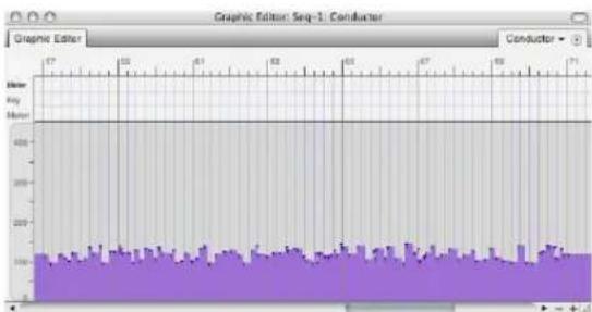
line
| Time | Meter | |------|-------| | 0 | 100 | | 1 | 150 | | 2 | 200 | | 3 | 250 | | 4 | 300 | | 5 | 350 | | 6 | 400 | | 7 | 450 | | 8 | 500 | | 9 | 550 | | 10 | 600 | | 11 | 650 | | 12 | 700 | | 13 | 750 | | 14 | 800 | | 15 | 850 | | 16 | 900 | | 17 | 950 | | 18 | 1000 | | 19 | 1050 | | 20 | 1100 | | 21 | 1150 | | 22 | 1200 | | 23 | 1250 | | 24 | 1300 | | 25 | 1350 | | 26 | 1400 | | 27 | 1450 | | 28 | 1500 | | 29 | 1550 | | 30 | 1600 | | 31 | 1650 | | 32 | 1700 | | 33 | 1750 | | 34 | 1800 | | 35 | 1850 | | 36 | 1900 | | 37 | 1950 | | 38 | 2000 | | 39 | 2050 | | 40 | 2100 | | 41 | 2150 | | 42 | 2200 | | 43 | 2250 | | 44 | 2300 | | 45 | 2350 | | 46 | 2400 | | 47 | 2450 | | 48 | 2500 | | 49 | 2550 | | 50 | 2600 | | 51 | 2650 | | 52 | 2700 | | 53 | 2750 | | 54 | 2800 | | 55 | 2850 | | 56 | 2900 | | 57 | 2950 | | 58 | 3000 | | 59 | 3050 | | 60 | 3100 | | 61 | 3150 | | 62 | 3200 | | 63 | 3250 | | 64 | 3300 | | 65 | 3350 | | 66 | 3400 | | 67 | 3450 | | 68 | 3500 | | 69 | 3550 | | 70 | 3600 | | 71 | 3650 | | 72 | 3700 | | 73 | 3750 | | 74 | 3800 | | 75 | 3850 | | 76 | 3900 | | 77 | 3950 | | 78 | 4000 | | 79 | 4050 | | 80 | 4100 | | 81 | 4150 | | 82 | 4200 | | 83 | 4250 | | 84 | 4300 | | 85 | 4350 | | 86 | 4400 | | 87 | 4450 | | 88 | 4500 | | 89 | 4550 | | 90 | 4600 | | 91 | 4650 | | 92 | 4700 | | 93 | 4750 | | 94 | 4800 | | 95 | 4850 | | 96 | 4900 | | 97 | 4950 | | 98 | 5000 | | Note: The actual values may vary due to the random nature of the data generation. The provided values are just an example. I have been calculated based on the formula 'Conductor'.Randomization can be used in conjunction with any curve
Randomization option is a check box option, which means that it can be used in conjunction with any of the tempo curves:

area
| X-Axis | Value | |---|---| | 57 | 0 | | 58 | 0 | | 59 | 0 | | 60 | 0 | | 61 | 0 | | 62 | 0 | | 63 | 0 | | 64 | 0 | | 65 | 0 | | 66 | 0 | | 67 | 0 | | 68 | 0 | | 69 | 0 | | 70 | 0 | | 71 | 0 |The same curve with randomization set to 2%.
Controlling the degree of randomization
The Randomize option is ideal for adding “human feel” to the tempos of a sequence. By controlling the range over which the randomizing occurs, you control the degree of that feel. You can specify the range either as a percentage or as a range of bpm. In either case, each tempo event generated is placed randomly within the range.
Emphasis
This sub-option causes the tendency of the randomization to be higher or lower within the specified range. Thus, if you wish to randomize the tempos within a certain range, but you wish them to tend to be higher, use a positive emphasis; use a negative emphasis if you wish them to tend to be towards the lower end of the range. A value of zero equals no emphasis, which causes the randomization to occur evenly within the range.
The effect of Density on randomization
A Fine density setting causes tempo events to be generated more frequently than a Course density setting. Notice that these two settings have an effect on the constant tempo curve, which normally only produce a single tempo event.
The Options button
Pressing the Options button cycles through the different combinations of entered/computed parameters for the selected curve. This allows you to specify the curve in a variety of manners. For example, if you select a constant curve, you can specify just the tempo or you can specify the End time, in which case the tempo will be calculated to make the end measure location occur at the end time.
If you are not working with externally imposed timings, as required in film and video work, you will probably not need to use the Options button.
VIEWING AND EDITING TEMPO CHANGES
Tempo change data is stored in the Conductor track for the Chunk. Tempo changes look like—and can be edited similarly to—continuous MIDI data (such as pitch bend or controller information) in the Conductor track editor windows.
Each tempo change has a time and a tempo value. The tempo has two parts, the tempo value in beats per minute and the beat value (e.g. 1/4 note, 1/8 note, etc.)
Editing tempo changes can be done in the Tracks window, Sequence Editor, Conductor track Event List or Conductor Track Editor. You can apply all the commands on the Edit menu to tempo changes. Make sure that tempo changes are selected in the View Filter (Setup menu).
Note that smooth tempo changes require a large number of discrete tempo changes very close together. Also note that Digital Performer's internal resolution of tempo events is much higher than that displayed in the Event List windows. So, tempo events that seem identical actually represent different tempos with higher resolutions than can be shown.
TEMPO EDITING RESOLUTION
Tempos can be manually edited to a resolution of a hundredth of a beat per minute. When you use the settings in the Change Tempo window, tempos are calculated to a much higher degree of accuracy.
CHANGING TEMPO ON-THE-FLY DURING PLAYBACK
You can use the Change Tempo command without stopping playback.
CHAPTER 59 Change Meter
OVERVIEW
Meters specify the way musical time is counted and measured. In Digital Performer, meters affect the way measure|beat|tick locations are displayed in the Counter, dialog boxes, and Event List windows. Meters also affect the Click and countoff. In addition, they impact the way information is displayed in Digital Performer's QuickScribe Editor. The Change Meter command (Project menu>Conductor Track>Change Meter) allows you to enter any number of meter changes in a sequence.
Change Meter quick reference....749
Change meter basics ....749
Using the Change Meter window....750
Viewing meter changes....753
Editing meter changes in the Conductor track .....753
Hints and examples ....753
CHANGE METER QUICK REFERENCE

Figure 59-1: The Change Meter window.
Meter marking: Displays the meter in standard musical format. Click on the numerator and/or denominator and type in new values to change it.
Start and End Locations: Displays the region over which the meter change takes effect. Click in the From box to set the starting location. Click in the To box to set the ending location. Click on the end of sequence button to extend the region to the end on the sequence.
Options: The Only move barlines option does not affect the actual events in the sequence. The Realign music automatically and Adjust durations options erase or change events to fit the meter.
Metronome Click value: Displays click associated with the meter change.
CHANGE METER BASICS
A meter consists of a beat value and the number of beats per measure. The beat value is generally the rhythmic pulse or beat of the music; a measure consists of a certain number of these beats. Digital Performer displays meters in the standard musical fashion as a fraction, with the beat value in the denominator (on the bottom) and the number of beats per measure in the numerator (on top). In Digital Performer, the numerator can be a value between 1 and 99. The denominator must be a power of 2 (1, 2, 4, 8, 16, 32, or 64).

A Meter Change event in Digital Performer consists of a meter displayed in this way, along with a metronome click setting, which determines how the click will behave. It also determines how often the Counter is updated during playback or recording.
The meter's denominator value, the beat value of the current tempo and the click settings are all related, though they need not be set to the same value. You may wish to have a meter of 4/4 with a tempo of half note = 180 with the metronome clicking every eighth note. The ability to use separate values allows a great deal of flexibility and accuracy during recording. In addition, the click can be fully, independently customized. You can even specify default click behavior for specific meters and tempo ranges. See “Click Changes” on page 734 and “Click Defaults” on page 258.
If a sequence or song contains several meters, the resulting configuration of meters is termed a meter map. This map is simply the complete set of programmed meter changes for an entire sequence. These changes are displayed in the Event List windows for each track in the sequence. The meter changes for a given sequence or song can only be altered in its Conductor track.
It is often useful to set up the meter map before recording the music, this way the measure locations of the events you record will stay consistent through the recording and editing process. If you change the meter after recording a track or tracks, the measure|beat|tick locations of the events may change.
Inserting a new meter may or may not have an audible effect on the music. Depending on the options you select for inserting a new meter, note events may be excluded and durations may change. These options are explained in detail below.
Digital Performer starts a new measure at every meter change. Thus, if a meter change is inserted in the middle of a measure, that measure will terminate early, and a new one will begin with the meter change event. See “Meter changes and partial measures” on page 738.
USING THE CHANGE METER WINDOW
Use these general guidelines for changing meter.
Specifying the sequence or song to insert meters into
If a Tracks window is active, the meter insertion will apply to that sequence. If the Chunks window is active, the meter insertion will apply to the highlighted Chunk or, if no Chunk is highlighted, to the current play-enabled Chunk. If an edit window is active, the meter insertion will apply to whatever sequence it belongs to.
When you open the Change Meter window (Project menu>Conductor Track>Change Meter), the name of the sequence or song in which the meter insertion will be placed is displayed at the top of the Change Meter window.
Entering the meter
Click in each box and type in the numbers. The numerator must be a value between 1 and 99. The denominator must be a standard note value: 1, 2, 4, 8, 16, 32 or 64.
Specifying the From and To locations
These locations specify the starting and ending locations for the meter change. Click on the fields and enter the desired measure|beat|tick values. If you have just entered a meter change, the From location is automatically set to the previous To location. Click on the end of sequence button to change meter from the From location to the end of the sequence.
Entering meters quickly one measure at a time
If you are going to be entering a series of meter changes quickly, choose the Next Measure option. This option lets you press the enter key once for each measure. If you have several measures in a row in the same meter, just press the enter key once for each measure. The “from” measure is automatically updated as you do so. This lets you enter meter changes efficiently for an entire sequence by quickly pressing the enter key repeatedly as many times as necessary for measures with the same meter. When you need to change meter, type in the new meter and press enter again as many times as necessary for the new meter. Keep going as long as necessary.
The metronome click
Each meter change can have its own unique metronome click setting. There are four choices for a meter change metronome click:
Metronome click For more information
| Default “Default for Meter” on page 260. |
| Tacet “Tacet click” on page 735. |
| Beat value “Beat Value” on page 260. |
Pattern "Pattern click" on page 735.
The measure range
When you enter a range of measures, Digital Performer will change the meter up to but not including the to measure. The to measure does not change; it remains in the same meter as before the operation. This is very similar to the way most
edit/region operations work; events at the end time are not affected. If you choose the end of sequence option, the meter change will continue to the end of the sequence, no matter how the sequence may change.
For example, assume a sequence is completely in 4/4. Entering a change to 3/4 from measure 8 to measure 12 will place a 3/4 meter change in measure 8, and a 4/4 meter change in measure 12. The result is that measures 8 through 11 are now in 3/4, and measure 12 remains in 4/4.
Realign music automatically
This option allows you to maintain the metrical structure of each measure by deleting some note events and changing the durations of others. There is a sub-option, Adjust durations, which is discussed below. The following assumes that the Adjust durations box is not checked. When you change the meter of a measure that contains note events with this option on, beats are either added or removed according to the new meter you specify. If beats are added, rests are inserted for the new beats. If beats are removed, any note event occurring in the removed beat will be removed as well. The durations of note events that start before the deleted beats are preserved. For example, suppose you have the following two measure passage in 4/4 time:

Graphically, the durations would be represented like this:

line
| Position | Value | |---|---| | 1 | 0 | | 2 | 0 | | 3 | 0 | | 4 | 0 | | 5 | 0 | | 6 | 0 | | 7 | 0 | | 8 | 0 | | 9 | 0 | | 10 | 0 | | 11 | 0 | | 12 | 0 | | 13 | 0 | | 14 | 0 | | 15 | 0 | | 16 | 0 | | 17 | 0 | | 18 | 0 | | 19 | 0 | | 20 | 0 | | 21 | 0 | | 22 | 0 | | 23 | 0 | | 24 | 0 | | 25 | 0 | | 26 | 0 | | 27 | 0 | | 28 | 0 | | 29 | 0 | | 30 | 0 | | 31 | 0 | | 32 | 0 | | 33 | 0 | | 34 | 0 | | 35 | 0 | | 36 | 0 | | 37 | 0 | | 38 | 0 | | 39 | 0 | | 40 | 0 | | 41 | 0 | | 42 | 0 | | 43 | 0 | | 44 | 0 | | 45 | 0 | | 46 | 0 | | 47 | 0 | | 48 | 0 | | 49 | 0 | | 50 | 0 | | 51 | 0 | | 52 | 0 | | 53 | 0 | | 54 | 0 | | 55 | 0 | | 56 | 0 | | 57 | 0 | | 58 | 0 | | 59 | 0 | | 60 | 0 | | 61 | 0 | | 62 | 0 | | 63 | 0 | | 64 | 0 | | 65 | 0 | | 66 | 0 | | 67 | 0 | | 68 | 0 | | 69 | 0 | | 70 | 0 | | 71 | 0 | | 72 | 0 | | 73 | 0 | | 74 | 0 | | 75 | 0 | | 76 | 0 | | 77 | 0 | | 78 | 0 | | 79 | 0 | | 80 | 0 | | 81 | 0 | | 82 | 0 | | 83 | 0 | | 84 | 0 | | 85 | 0 | | 86 | 0 | | 87 | 0 | | 88 | 0 | | 89 | 0 | | 90 | 0 | | 91 | 0 | | 92 | 0 | | 93 | 0 | | 94 | 0 | | 95 | 0 | | 96 | 0 | | 97 | 0 | | 98 | 0 | | 99 | 0 | | A (end) | A (end) |Figure 59-2: Original music, before changing meter.
Changing the meter to 3/4 and using the Realign music automatically without adjusting durations, the fourth beats would be removed. This would remove the quarter note in the first measure but not the whole note since it began before the deleted (fourth) beat:

Figure 59-3: Realign music automatically.
Adjust durations
The Adjust durations sub-option can only be used when the Realign music automatically option is selected. The Adjust durations sub-option alters the durations of notes that begin before the removed or added beats. The durations are altered to conform to the new measure boundaries. In the example above, the original version in 4/4 has a note lasting the whole second measure. With the Adjust durations option on, the duration of this note is altered such that the note will last for the entire measure in the new meter:

Figure 59-4: Adjust durations option.
Don't move locked markers
When the Don't move locked markers option in the Change Meter dialog (Figure 59-1 on page 749) is checked, locked markers are not moved by the change meter operation and remain anchored to their SMPTE time code frame position.
Only move barlines
This option does not change any durations. It imposes the new barline structure over the music, keeping all durations the same. The above original 4/4 passage would look like this with the Only move barlines option:
Original music
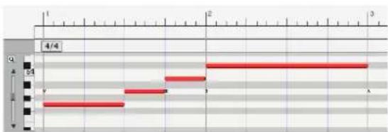
bar
| Position | Value | |---|---| | 1 | 0 | | 2 | 0 | | 3 | 54 | | 4 | 54 | | 5 | 0 | | 6 | 0 | | 7 | 0 | | 8 | 0 | | 9 | 0 | | 10 | 0 | | 11 | 0 | | 12 | 0 | | 13 | 0 | | 14 | 0 | | 15 | 0 | | 16 | 0 | | 17 | 0 | | 18 | 0 | | 19 | 0 | | 20 | 0 | | 21 | 0 | | 22 | 0 | | 23 | 0 | | 24 | 0 | | 25 | 0 | | 26 | 0 | | 27 | 0 | | 28 | 0 | | 29 | 0 | | 30 | 0 | | 31 | 0 | | 32 | 0 | | 33 | 0 | | 34 | 0 | | 35 | 0 | | 36 | 0 | | 37 | 0 | | 38 | 0 | | 39 | 0 | | 40 | 0 | | 41 | 0 | | 42 | 0 | | 43 | 0 | | 44 | 0 | | 45 | 0 | | 46 | 0 | | 47 | 0 | | 48 | 0 | | 49 | 0 | | 50 | 0 | | 51 | 0 | | 52 | 0 | | 53 | 0 | | 54 | 0 | | 55 | 0 | | 56 | 0 | | 57 | 0 | | 58 | 0 | | 59 | 0 | | 60 | 0 | | 61 | 0 | | 62 | 0 | | 63 | 0 | | 64 | 0 | | 65 | 0 | | 66 | 0 | | 67 | 0 | | 68 | 0 | | 69 | 0 | | 70 | 0 | | 71 | 0 | | 72 | 0 | | 73 | 0 | | 74 | 0 | | 75 | 0 | | 76 | 0 | | 77 | 0 | | 78 | 0 | | 79 | 0 | | 80 | 0 | | 81 | 0 | | 82 | 0 | | 83 | 0 | | 84 | 0 | | 85 | 0 | | 86 | 0 | | 87 | 0 | | 88 | 0 | | 89 | 0 | | 90 | 0 | | 91 | 0 | | 92 | 0 | | 93 | 0 | | 94 | 0 | | 95 | 0 | | 96 | 0 | | 97 | 0 | | 98 | 0 | | 99 | 0 | | Note: The values in the chart are estimated based on the provided code. The actual data values are not explicitly provided in the image. The numbers in the chart are estimated based on the given code.Realigned using the Only Move Barlines option

Figure 59-5: Only move barlines option.
VIEWING METER CHANGES
The meter changes in a sequence can be viewed in all editor windows. Meter changes can be edited only in the Conductor track; they cannot be modified in the editor windows for MIDI and audio tracks.
Meters can be hidden from editor windows by turning off their display with the View Filter. Conversely, the entire meter map may be viewed alone by turning off the display of all other types of events.
EDITING METER CHANGES IN THE CONDUCTOR TRACK
Meter changes can be edited directly in either edit window (Event List or MIDI Editing) for the Conductor track. See “Clips and Conductor Track data” on page 444 and “Editing in the Conductor Track” on page 434 for details.
Using edit menu commands with meter changes
You can apply any editing command to meters in the Conductor track: they can be cut, copied, pasted, spliced, etc., just like other events. You can do so using all of the same techniques for editing MIDI and audio events. You can even edit meter changes along with MIDI data in other tracks by selecting the Conductor track along with the other tracks.
When cutting, copying, and pasting meter changes, it is strongly advised that you leave the Fix partial measures automatically preference (Digital Performer menu) checked. This preference helps avoid partial measures, which in most cases you do not want to create with editing operations.
HINTS AND EXAMPLES
Editing meter changes can be confusing, especially if you create partial measures by unknowingly putting a meter change in the middle of an existing measure. Another way to avoid partial measures is to turn on (check) the Smart Selections command in the Edit menu. Smart Selections helps to avoid partial measures.
Erasing the meter map to start over
If you feel that your meter map has become too complicated, has errors that you can't easily detect, or has somehow become excessively complex, you can delete it and re-enter it correctly from the start.
To erase the current meter map:
1 Open the Selection Information window.
2 Choose Set to Chunk Bounds from the Set To menu.
This loads the start and end times of the entire sequence in the Selection Bar.
3 Select the Conductor track by clicking on it in the Tracks Overview or Sequence Editor.
4 Choose View Filter from the View menu.
5 Make sure the menu at the top of the window says Global View Filter.
6 Uncheck all check boxes except for meter changes.
Hold down the Option/Alt key and click on the meter change check box. Now the Edit commands will only affect meter changes.
7 Choose Erase from the Edit menu.
This gets rid of all the meter changes for the sequence.
8 Restore your previous View Filter settings.
Always try to remember to reset the View Filter immediately after using it.
Pasting into the conductor track
Be careful when pasting into the Conductor track: pasting replaces events of all types selected in the View Filter. This may be what you want. If, however, you are just rearranging meters and wish to leave the other data where it is, make sure to set the View Filter for meter changes only.
Inserting measures with a different meter
Here's a method for inserting a number of new measures with a different meter into your sequence:
1 Use the Insert Measures command to insert the desired number of measures.
See chapter 61, “Insert Measures” (page 759) for details. The newly inserted measures will have the existing meter at the point of insertion.
2 Choose Project menu>Conductor Track>Change Meter.
3 Set the From and To locations to match the new range of blank measures you just inserted.
4 Click on the Realign Music Automatically option.
Leave the Adjust durations box unchecked. This option adds or subtracts the necessary number of beats to ensure that new measures line up with the new meter.
5 Click on the Change button.
This enters the meter change.
Getting rid of partial measures
In the Preferences window in the Digital Performer menu (macOS) or Edit menu (Windows), there is a preference called Fix partial measures automatically. If Fix partial measures automatically is turned on (checked), and you open a Digital Performer file that has partial
measures, it will automatically get rid of the partial measures by moving meter changes as needed to do so. After the file opens, you should check to see if your MIDI data still lines up with all the barlines the way you want, and make adjustments with the Change Meter and/or Shift features as desired. If you want to get rid of partial measures in your files, leave this option turned on. If you want to preserve partial measures in a file, uncheck this option before opening the file. Don't worry, however: Digital Performer presents an alert before it corrects partial measures so that you can Revert to Saved if you decide not to do so.
CHAPTER 60 Change Key
OVERVIEW
Key signatures provide a way to interpret MIDI note data. In music notation, there are several ways to write every pitch. For example, although G sharp and A flat sound the same and describe the same pitch, a G sharp would make less sense in the key of E flat than an A flat would. Digital Performer allows you to specify key signatures in your sequences, making the display of notes in the Event List windows clear and musically accurate. Key signatures are also extremely important when viewing a sequence in music notation with Digital Performer's QuickScribe Editor; setting the correct key signatures ensures that the music will be properly notated.
Change key Quick Reference....755
Change Key basics....755
Types of key signatures....756
Inserting key signatures....756
Viewing and editing key changes....757
CHANGE KEY QUICK REFERENCE
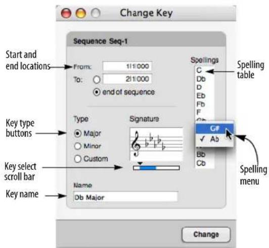
Figure 60-1: Change Key (Project menu>Conductor Track>Change Key).
Start and End Locations: Displays the region over which the key change occurs. Click on a value to highlight it, and type the desired starting and ending measure locations. After each change is made, the From location is set to the previous To location. Click on the end of sequence button to change key from the From location to the end of the sequence.
Key type: Click on the appropriate radio button to select a Major, Minor, or user-defined Custom key.
Key Signature Scroll Box: Use the scroll bar and arrows to select the desired key signature. Changing the key in this box automatically updates the key name and spelling table.
Key Name: Displays the name of the key signature. The name appears as the key change event in the Event List windows. The name is set automatically when the Major or Minor key types are chosen. Click the name and type to change it.
Spelling Table: Displays the spelling of the twelve chromatic notes for the currently selected key. Change a spelling by pressing on the note letter and selecting the desired spelling from the menu that appears.
CHANGE KEY BASICS
Key signatures in the Conductor track of a sequence apply to all the tracks in the sequence. At any given location, there can be only one key signature for all tracks. You can have as many key changes as you like in a sequence.
Key changes appear for reference in all track editor windows. They may be edited only in the Conductor track, directly in the Conductor track Event List, MIDI Editor, Sequence Editor or
Tracks window. Each key change affects the spelling of notes to just before the beginning of the next key change. Key changes only affect the display of note pitches; they do not change the actual MIDI data in your sequence.
If there is no key signature entered at the beginning of the sequence, the default key is C major (no sharps or flats).
It is possible to put key changes in the Conductor track of a song, but they will have no effect on the spellings of notes in sequences contained in the song. Only key changes in the Conductor track of the sequence will affect notes within that sequence.
TYPES OF KEY SIGNATURES
Key signatures in Digital Performer actually have two components: the standard key signature (up to seven sharps or seven flats), and note-spelling assignments for non-diatonic notes (notes not in the basic scale of the key). A key has five non-diatonic notes; Digital Performer allows you to decide how each of them will be spelled. In the key of D, for instance, you can name the note that lies between B and C sharp either B sharp or C natural.
You can choose from three types of key signatures:
■ Major: Any key from C sharp major (7 sharps) to C flat major (7 flats)
■ Minor: Any key from A sharp minor (7 sharps) to A flat minor (7 flats)
■ Custom: You can choose a signature with 7 sharps to 7 flats and call it what you wish. This is useful for modal key signatures: C Phrygian, for example, has 4 flats. The key signature name is only for your reference: only the key signature itself is displayed on the staff in the QuickScribe Editor.
INSERTING KEY SIGNATURES
To insert a key signature or add a key change, keep these guidelines in mind when using the Change Key window (Project menu>Conductor Track>Change Key).
Specifying the sequence or song to insert a key change into
If a Tracks window is active, the key insertion will apply to that sequence. If the Chunks window is active, the key insertion will apply to the highlighted Chunk or, if no Chunk is highlighted, to the current play-enabled Chunk. If an edit window is active, the key insertion will apply to whatever sequence it belongs to.
When you open the Change Key window (Project menu>Conductor Track>Change Key), the name of the sequence in which the key change will be placed is displayed at the top of the dialog box.
Specifying the From and To locations
These locations specify the starting and ending locations for the key change. Click on the fields and enter the desired measure|beat|tick values. If you have just entered a key change, the From location is automatically set to the previous To location. Click on the end of sequence button to change key from the From location to the end of the sequence.
Choosing note spellings
Click on each note in the spellings list to select it and choose the desired spelling from the available ones displayed.
VIEWING AND EDITING KEY CHANGES
The key changes in a sequence can be viewed in all editor windows. Key changes can be edited only in the Conductor track; they cannot be modified in the editor windows for MIDI and audio tracks.
Key changes can be hidden from editor windows by turning off their display with the View Filter. Conversely, the entire key change map may be viewed alone by turning off the display of all other types of events.
In the Event List for the Conductor Track, the location of a key change can be edited by altering its starting time. The key change itself may be modified by double-clicking it. The Change Key dialog box appears in which you can enter the modification (Figure 60-2 below). The box that appears is slightly different than the one chosen with the Change Key command: the Change button is replaced by OK and Cancel buttons, and the sequence name and From and To location fields are missing. Otherwise, this box works exactly as described above.

Figure 60-2: When you double-click on a key change event in the Conductor track Event List, the Change Key dialog box appears. These settings are the same as the Change Key window (Figure 60-1 on page 755).
Using the edit commands with key changes
You can apply the commands from the Edit menu to key changes in the Conductor track: key signatures can be cut, copied, pasted, spliced, etc.,
just like other events. The region to edit in the Conductor track may be selected by highlighting events in its Event List window or clicking on the Conductor track to highlight it and specifying a region in the Selection Bar. Key change information can be included in an edit operation involving note and other MIDI events by including the Conductor track along with the selected tracks.
CHAPTER 61 Insert Measures
OVERVIEW
The Insert Measures command (Project menu>Conductor Track>Insert Measures) lets you add any number of new, empty measures at any point in the sequence. This features has an option that preserves all subsequent SMPTE locations after the insertion, if desired. For example, if you were working on a film cue, and you needed to add ten measures of extra music before the current start time of the cue, the Insert Measures command lets you insert 10 empty measures at the beginning of the sequence, while at the same time preserving all your existing material's relationship to SMPTE time code.
type in the number of measures you want to insert and the downbeat where you wish to insert them. If you wish to preserve the SMPTE times of all events after the insertion point, check the option called Maintain all times following the insert point.

Figure 61-1: Insert Measures.
BEFORE YOU USE INSERT MEASURES
The Insert Measures command automatically splits audio regions at the point of insertion. But it does not split MIDI notes. If MIDI notes extend through the insertion point, such as sustained chords, and you would like to split them, do the following before using the Insert Measures command: make a selection in the desired tracks with one edge of the selection at the split point. Then use the Split command in the Edit menu to split the MIDI notes.
USING THE INSERT MEASURES COMMAND
You don't need to select anything before using the Insert Measures command. Just choose it from the Conductor Track sub-menu in the Project menu,
CHAPTER 62 Adjust Beats
OVERVIEW
Adjust Beats (Project menu>Conductor Track>Adjust Beats) lets you align Digital Performer's time ruler to music (either MIDI or audio) in cases where the Beat Detection Engine and tempo analysis features are not suited for the material. For example, you might be importing a full mix of a rubato performance for which the Beat Detection Engine cannot accurately detect beats and tempo.
The problem ....761
Using Adjust Beats....761
THE PROBLEM
Adjust Beats addresses the following problem: you've just imported an audio file into Digital Performer — or you recorded it without listening to Digital Performer's metronome — and the audio is completely out of sync with the sequence's tempo, beats and barlines. In addition, it cannot be accurately processed by the Beat Detection Engine or tempo analysis features because of the nature of the material.
How do you get Digital Performer's measures and beats to line up with the audio?
USING ADJUST BEATS
The audio used in this example (Figure 62-1) is a simplified example for the purposes of demonstrating the Adjust Beats command. Note, however, that audio of this nature (monophonic audio with clearly defined transients) can be quite successfully analyzed with the Beat Detection Engine and should be aligned to the sequence tempo using beats and tempo analysis.
To use the Adjust Beats command to get Digital Performer's beats and barlines to line up with audio:
1 Place the soundbite in a track.

Figure 62-1: A rubato soundbite imported into a new sequence in Digital Performer. Notice that the measures and beats don't line up with the beat spikes in the audio waveform because their tempos do not match. (The sequence currently has a constant tempo; the soundbite has a changing tempo.)
2 Choose Project menu>Conductor Track>Adjust Beats.
3 Turn on Adjust Beats (check the box).
4 Adjust beats lets you adjust entire measures or specific beats. In this example, we'll start adjusting the first measure and then fine-tune the beats, so for now, the Adjust menu is set to measures, and we'll set the other options as shown below for now.

5 Zoom the Sequence Editor so you can easily see the beats in the waveform (you can even use the Zoom tool in the time ruler).

6 In this simplified example, the downbeat of measure two is shown above. With Adjust Beats, we can simply drag the downbeat of measure 2 in the time ruler over to the downbeat in the waveform. You can grab measure two by either clicking on the time ruler or clicking directly on the waveform below it.

Figure 62-2: Using Adjust Beats to line up time ruler (the sequence's measures and beats) with audio. After dragging the down beat of measure 2 in the time ruler, it now matches the audio.
7 Since the audio does not have a constant tempo, we now need to use the same technique to line up the beats in measure 1. First, we'll switch the Adjust pop-up menu in the Adjust Beats window to Beats and choose the Move one beat at a time option.
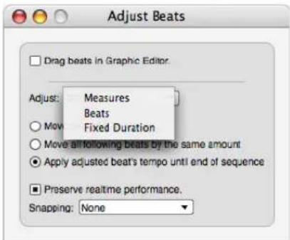
Figure 62-3: Switching to beat adjustment, moving one beat at a time.
8 Now we can line up the beats in measure one by dragging them in the time ruler to match the beat spikes in the audio waveform.

Figure 62-4: Adjusting the beats in measure 1. Above, beat four is being adjusted, and below, the final results.
You can continue this process for any portion of the audio, adjusting measures for larger scale changes and using beat adjustment for fine-tuning.
The end result of this simple procedure is that the audio sounds the same: it plays exactly as it did originally. But now, the sequence has a rubato tempo map that was generated by your graphic adjustments — and its changing tempos will exactly match the changing tempos of the audio.

Figure 62-5: This is the tempo map that was generated by beat adjustments made in example. These tempo changes make the sequence play along exactly with the rubato audio passage. (And the beats and barlines match up, too.)
Adjust Beats and grid lines
Adjust Beats displays grid lines as follows:
■ If the time ruler is displaying measures only, no grid lines are displayed.
■ If an auxiliary time ruler is being displayed, Adjust Beats displays grid lines for the aux ruler.
Grid lines for a mensural auxiliary ruler are shown every measure.
Grid lines for real-time aux rulers (real time, SMPTE or samples) are shown at intervals representing the primary unit of measurement being displayed in the ruler (such as one-second intervals, for example).
Adjust beats and snapping
Adjust Beats can snap to audio beats and MIDI notes, if any, in the track you are dragging in. They can also snap to markers.
In the MIDI Editor, beats will snap to any visible MIDI notes.
In the Sequence Editor, your cursor actions snap to the MIDI notes or audio beats in the track currently beneath the cursor. Just move the cursor over the track you wish to snap to.

Figure 62-6: Adjust Beats can now snap to audio beats as well as MIDI notes.
CHAPTER 63 Record Beats
OVERVIEW
The Record Beats command (Project menu>Conductor Track>Record Beats) allows you to record music without listening to a metronome click and then afterwards realign Digital Performer's internal beats and barlines with the music you recorded.
Record Beats example....765
Using Record Beats....766
Handling odd meters....767
Handling pick up beats with the shift data to option . . .768
Recording beats while slaved to tape....768
RECORD BEATS EXAMPLE
Here's a simple example. The MIDI Editor below is the tune Mary Had a Little Lamb recorded without Digital Performer's metronome click:

line
| X-Axis | Y-Axis | |---|---| | 1 | 0.5 | | 2 | 0.45 | | 3 | 0.5 | | 4 | 0.45 | | 5 | 0.5 | | 6 | 0.45 | | 7 | 0.5 | | 8 | 0.45 | | 9 | 0.5 | | 10 | 0.45 | | 11 | 0.5 | | 12 | 0.45 | | 13 | 0.5 | | 14 | 0.45 | | 15 | 0.5 | | 16 | 0.45 | | 17 | 0.5 | | 18 | 0.45 | | 19 | 0.5 | | 20 | 0.45 | | 21 | 0.5 | | 22 | 0.45 | | 23 | 0.5 | | 24 | 0.45 | | 25 | 0.5 | | 26 | 0.45 | | 27 | 0.5 | | 28 | 0.45 | | 29 | 0.5 | | 30 | 0.45 | | 31 | 0.5 | | 32 | 0.45 | | 33 | 0.5 | | 34 | 0.45 | | 35 | 0.5 | | 36 | 0.45 | | 37 | 0.5 | | 38 | 0.45 | | 39 | 0.5 | | 40 | 0.45 | | 41 | 0.5 | | 42 | 0.45 | | 43 | 0.5 | | 44 | 0.45 | | 45 | 0.5 | | 46 | 0.45 | | 47 | 0.5 | | 48 | 0.45 | | 49 | 0.5 | | 50 | 0.45 | | 51 | 0.5 | | 52 | 0.45 | | 53 | 0.5 | | 54 | 0.45 | | 55 | 0.5 | | 56 | 0.45 | | 57 | 0.5 | | 58 | 0.45 | | 59 | 0.5 | | 60 | 0.45 | | 61 | 0.5 | | 62 | 0.45 | | 63 | 0.5 | | 64 | 0.45 | | 65 | 0.5 | | 66 | 0.45 | | 67 | 0.5 | | 68 | 0.45 | | 69 | 0.5 | | 70 | 0.45 | | 71 | 0.5 | | 72 | 0.45 | | 73 | 0.5 | | 74 | 0.45 | | 75 | 0.5 | | 76 | 0.45 | | 77 | 0.5 | | 78 | 0.45 | | 79 | 0.5 | | 80 | 0.45 | | 81 | 0.5 | | 82 | 0.45 | | 83 | 0.5 | | 84 | 0.45 | | 85 | 0.5 | | 86 | 0.45 | | 87 | 0.5 | | 88 | 0.45 | | 89 | 0.5 | | 90 | 0.45 | | 91 | 0.5 | | 92 | 0.45 | | 93 | 0.5 | | 94 | 0.45 | | 95 | 0.5 | | 96 | 0.45 | | 97 | 0.5 | | 98 | 0.45 | | 99 | 0.5 | | Note: The y-values are estimated based on the data provided in the code above the chart title bar (e.g., 'y = '). The y-axis label is 'N'. The x-axis label is 'Time' (labeled as 'x'). The chart title bar is 'Time' and axis labels are 'x'. The legend is not present in the image.Figure 63-1: Mary Had a Little Lamb recorded in the MIDI Editor without using the metronome click. Notice that the first note is not on beat 1 and that none of the downbeats in the music match the downbeats in the measure ruler above.
Notice that the music does not line up with the beats and barlines in the measure|beat|tick ruler. This prevents many useful editing tasks, such as quantizing and easy region selection.
After using the Record Beats command, Digital Performer's beats and barlines have been realigned to match the beats in Mary Had a Little Lamb:

line
| X-Axis | Y-Axis | |---|---| | 1 | 0.5 | | 2 | 0.6 | | 3 | 0.7 | | 4 | 0.8 | | 5 | 0.9 | | 6 | 1.0 | | 7 | 0.9 | | 8 | 0.8 | | 9 | 0.7 | | 10 | 0.6 | | 11 | 0.5 | | 12 | 0.4 | | 13 | 0.3 | | 14 | 0.2 | | 15 | 0.1 | | 16 | 0.0 | | 17 | -0.1 | | 18 | -0.2 | | 19 | -0.3 | | 20 | -0.4 | | 21 | -0.5 | | 22 | -0.6 | | 23 | -0.7 | | 24 | -0.8 | | 25 | -0.9 | | 26 | -1.0 | | 27 | -1.1 | | 28 | -1.2 | | 29 | -1.3 | | 30 | -1.4 | | 31 | -1.5 | | 32 | -1.6 | | 33 | -1.7 | | 34 | -1.8 | | 35 | -1.9 | | 36 | -2.0 | | 37 | -2.1 | | 38 | -2.2 | | 39 | -2.3 | | 40 | -2.4 | | 41 | -2.5 | | 42 | -2.6 | | 43 | -2.7 | | 44 | -2.8 | | 45 | -2.9 | | 46 | -3.0 | | 47 | -3.1 | | 48 | -3.2 | | 49 | -3.3 | | 50 | -3.4 | | 51 | -3.5 | | 52 | -3.6 | | 53 | -3.7 | | 54 | -3.8 | | 55 | -3.9 | | 56 | -4.0 | | 57 | -4.1 | | 58 | -4.2 | | 59 | -4.3 | | 60 | -4.4 | | 61 | -4.5 | | 62 | -4.6 | | 63 | -4.7 | | 64 | -4.8 | | 65 | -4.9 | | 66 | -5.0 | | 67 | -5.1 | | 68 | -5.2 | | 69 | -5.3 | | 70 | -5.4 | | 71 | -5.5 | | 72 | -5.6 | | 73 | -5.7 | | 74 | -5.8 | | 75 | -5.9 | | 76 | -6.0 | | 77 | -6.1 | | 78 | -6.2 | | 79 | -6.3 | | 80 | -6.4 | | 81 | -6.5 | | 82 | -6.6 | | 83 | -6.7 | | 84 | -6.8 | | 85 | -6.9 | | 86 | -7.0 | | 87 | -7.1 | | 88 | -7.2 | | 89 | -7.3 | | 90 | -7.4 | | 91 | -7.5 | | 92 | -7.6 | | 93 | -7.7 | | 94 | -7.8 | | 95 | -7.9 | | 96 | -8.0 | | 97 | -8.1 | | 98 | -8.2 | | 99 | -8.3 | | 100 | -8.4 |Figure 63-2: Mary Had a Little Lamb after using the Record Beats command. Notice that the beats and barlines in the time ruler now match the downbeats in the music. Also note that the music plays back exactly the same way as the original recording (as long as the Tempo Control in the Metronome is set to the Conductor track).
It is important to note that Digital Performer's beats have been realigned to the music, not the other way around. The music plays back in the same fashion as the original recording. When using Record Beats, you are in no jeopardy of losing the original feel of your performance. Digital Performer accomplishes this by creating a tempo map at the same time as realigning the beats. Thus, Digital Performer's beats speed up and slow down to match the original performance.
After beats and barlines have been realigned, many useful editing commands can be employed that were not possible beforehand. For example, the above tune can now be successfully quantized for rhythmic accuracy and transcription:

line
| Time | Value | |------|-------| | 1 | 3 | | 2 | 2 | | 3 | 3 | | 4 | 2 | | 5 | 3 | | 6 | 2 | | 7 | 3 | | 8 | 2 | | 9 | 3 | | 10 | 2 | | 11 | 3 | | 12 | 2 | | 13 | 3 | | 14 | 2 | | 15 | 3 | | 16 | 2 | | 17 | 3 | | 18 | 2 | | 19 | 3 | | 20 | 2 | | 21 | 3 | | 22 | 2 | | 23 | 3 | | 24 | 2 | | 25 | 3 | | 26 | 2 | | 27 | 3 | | 28 | 2 | | 29 | 3 | | 30 | 2 | | 31 | 3 | | 32 | 2 | | 33 | 3 | | 34 | 2 | | 35 | 3 | | 36 | 2 | | 37 | 3 | | 38 | 2 | | 39 | 3 | | 40 | 2 | | 41 | 3 | | 42 | 2 | | 43 | 3 | | 44 | 2 | | 45 | 3 | | 46 | 2 | | 47 | 3 | | 48 | 2 | | 49 | 3 | | 50 | 2 | | 51 | 3 | | 52 | 2 | | 53 | 3 | | 54 | 2 | | 55 | 3 | | 56 | 2 | | 57 | 3 | | 58 | 2 | | 59 | 3 | | 60 | 2 | | 61 | 3 | | 62 | 2 | | 63 | 3 | | 64 | 2 | | 65 | 3 | | 66 | 2 | | 67 | 3 | | 68 | 2 | | 69 | 3 | | 70 | 2 | | 71 | 3 | | 72 | 2 | | 73 | 3 | | 74 | 2 | | 75 | 3 | | 76 | 2 | | 77 | 3 | | 78 | 2 | | 79 | 3 | | 80 | 2 | | 81 | 3 | | 82 | 2 | | 83 | 3 | | 84 | 2 | | 85 | 3 | | 86 | 2 | | 87 | 3 | | 88 | 2 | | 89 | 3 | | 90 | 2 | | 91 | 3 | | 92 | 2 | | 93 | 3 | | 94 | 2 | | 95 | 3 | | 96 | 2 | | 97 | 3 | | 98 | 2 | | 99 | 3 | | Note: The actual values may vary due to the random nature of the data generation. The provided values are just an example. I have left blank text in the code. The actual text is not present in the image. You would need to run the code if you want to run the code to get the actual text. You would need to run the code if you want to run the code to get the actual text. You would need to run the code if you want to run the code to get the actual text. You would need to run the code if you want to run the code to get the actual text. You would need to run the code if you want to run the code to get the actual text. You would need to run the code if you want to run the code to get the actual time. You would need to run the code if you want to run the code to get the actual time. You would need to run the code if you want to run the code to get the actual time. You would need to run the code if you want to run the code to get the actual time. You would need to run the code if you want to run the code to get the actual time. You would need to run the code if you want to run the code to get the actual type. You would need to run the code if you want to run the code to get the actual type. You would need to run the code if you want to run the code to get the actual type. You would need to run the code if you want to run the code to get the actual type. You would need to run the code if you want to run the code to get the actual type. You would need to run the code if you want to run the code to get the actual types. You would need to run the code if you want to run the code to get the actual types. You would need to run the code if you want to run the code to get the actual types. You would need to run the code if you want to run the code to get the actual types. You would need to run the code if you want to run the code to get the actual types. You would need to run the code if you want to run the code to get the actual type. You would need to run the code if you want to run the code to get the actual type. You would need to run the code if you want to run the code to get the actual type. You would need to run the code if you want to run the code to get the actual type. You would need to run the code if you want to run the code to get the actual Type. You would need to run the code if you want to run the code to get the actual Type. You would need to run the code if you want to run the code to get the actual Type. You would need to run the code if you want to run the code to get the actual Type. You would need to run the code if you want to run the code to get the actual Type. You would need to run the code if you want to run the code to get the actual type. You would need to run the code if you want to run the code to get the actual Type. You would need to run the code if you want to run the code to get the actual Type. You would need to run the code if you want to run the code to get the actual Type. You would need to run the code if you want to run the code to get the actual type. You would need to run the code if you want to run the code to get the actual type. You would need to run the code if you want to run the code to get the actual Type. You would need to run the code if you want to run the code to get the actual Type. You would need to run the code if you want to run the code to get the actual type. You would need to run the code if you want to run the code to get the actual Type. You would need to run the code if you want to run the code to get the actual type. You would need to run the code if you want to run the code to get the actual Type. You would need to run the code if you want to run the code to get the actual Type. You would need to run the code if you want to run the code to get the actual type. You would need to run the code if you want to run the code to get the actual type. You would need to run the code if you want to run the code to get the actual type. You would need for this example (e.g., “#”, “#”, “#”, etc.).Figure 63-3: After using Record Beats, music can be quantized, groove quantized, and edited.
USING RECORD BEATS
To use Record Beats:
1 Record music into a track.
You can play as freely as you like. Pay no attention to Digital Performer's Counter window. You can even turn off the Metronome click.
2 Open the Event List and make note of the time of the first event.
In the Mary Had a Little Lamb example above, the first note occurred at 1|2|132:

3 Set the Main Counter to the same time as the first event.
In this example, we enter 1|2|132 into the main Counter.
4 Choose Project menu>Conductor Track>Record Beats.
The Record Beats dialog box will appear.

5 Use the OK is first beat option.
This option means that Digital Performer will place the first downbeat right at the current counter location, which is 1|2|115, the location of the first note in this example.
6 Check the Shift data to option and type in the measure and beat at which you want to place the first downbeat.
For example, if the first note of music should be at measure 1, beat 4, as a pickup note, type in measure 1, beat 4. Be sure that the location you choose here is NOT before the sequence start.
7 Prepare to tap any note on your MIDI controller.
Get ready to tap along with the music you played.
8 When you are ready, click OK and begin tapping on the second beat.
With the OK is first beat option, Digital Performer begins playback and taps the first beat for you at the starting location of the Counter. In this example, Digital Performer places the first tap at 1|2|115. You should then begin tapping on the second beat. If you miss the second beat, stop, Undo, and try again.
9 Keep tapping along with the beats in your music as accurately as you can.
10 When you reach the end of the piece, click Stop.
Digital Performer may take moment to realign the beats and enter the newly generated tempo data in the Conductor track.
After Digital Performer calculates the changes, the downbeat of your music will now be at the measure and beat that you indicated with the Shift data to option. In addition, the Counter will beat
in 4/4 time on the downbeats that you tapped. To change the meter, refer to the “Handling odd meters” later in this chapter.
Listening to what you have done
To listen to the result of your tapping:
1 Choose Conductor track from the tempo control menu in the Control Panel.
Digital Performer will now play back according to the new tempo map in the Conductor track.
2 Press the Play button.
The music will sound the same, and the metronome and Counter windows will line up with the music as accurately as you tapped while Recording Beats.
Using a countoff and the tap first beat option
The Tap first beat option in the Record Beats dialog box allows you to tap the first beat when you recorded a countoff at the beginning of your original performance, or a visual cue on film or video at which to start tapping.
In this case, you have an aural or visual cue before the first tap that allows you to prepare to hit the first tap accurately.
To use the Tap first beat option:
1 Set the counter to a position several seconds before the first tap.
This will give you enough time to prepare for the first tap. You can have as much preroll time as you like to get ready for the first beat.
2 Choose Record Beats and select the Tap first beat option.
3 Click OK to begin Recording Beats.
Digital Performer will begin playing back. Listen carefully to the countoff or music and get ready for your first tap. Digital Performer will not begin recording beats until your first tap.
4 Begin tapping on the downbeat where you would like to begin realigning beats.
5 If you are punching out, click Stop immediately after your last tap.
This prevents music after the punch-out time from being realigned inadvertently. Digital Performer may take a moment to realign the beats.
HANDLING ODD METERS
The Record Beats command realigns your original Digital Performer into a default meter of 4/4 time. However, if you would like the music to be expressed in an odd meter or in changing meters, you can do so by using the Change Meter command after using Record Beats.
For example, let's say that you would like to bar your music in 6/8 time. After using Record Beats, it will be in 4/4 time. To convert it to 6/8, open the Change Meter dialog box, type in 6/8 as the meter, set the beat value to a dotted quarter note, choose the measure range you wish to convert to 6/8, select the Only move barlines option, and click Change. This will re-bar the music in 6/8 time without changing the playback of the music. See chapter 59, "Change Meter" (page 749).

HANDLING PICK UP BEATS WITH THE SHIFT DATA TO OPTION
The Shift data to option allows you to determine the placement of the first downbeat of the re-recorded beats. The most important thing to remember is this: do not choose a beat that occurs before the Chunk Start Time. For example, let's say that your music has two pickup beats and that you would like the following downbeat to occur at 1|1|000. Before you use Record Beats, create a pickup measure from 0|1|000 to 1|1|000 to accommodate the two pickup beats at 0|3|000 and 0|4|000.
To create a pickup measure:
1 Choose Set Chunk Start Time from the Sequence menu in the Control Panel to open the Set Chunk Start dialog box.
2 Set the Measure Start Time to 0.
If you need two measures of pickup, set the Measure start time to -1.

3 Click OK.
Now, when you press Rewind back to the beginning of the sequence, the Counter window will read 0|1|000.
After you have set up measure 0, you can set the Shift data to option in the Record Beats dialog box to measure 0, beat 3 to accommodate the two pickup beats in your music, and the first downbeat will occur at 1|1|000.
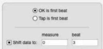
Record Beats may also be used while Digital Performer is slaved SMPTE time code via Direct Time Lock or MIDI Time Code. This allows you to freely record music while slaving Digital Performer to film or video without being concerned with Digital Performer's metronome. After recording, you can then line up the beats and barlines afterwards with Record Beats.
Here are a several important preparations you will need to make to Record Beats while slaved to tape:
■ Establish lockup to tape using MIDI Time Code and a SMPTE-to-MIDI converter such as MOTU's MIDI Timepiece™ AV. For more information, see chapter 86, "Receive Sync" (page 977).
■ Either before or after you record your music, make sure the first downbeat of the music occurs at the very beginning of the sequence and set the SMPTE Chunk Start Time so that the music starts at the desired SMPTE frame. You can either record the music this way, or shift the music after recording. This makes it easy to play the first beat accurately when you Record Beats.
- Set up a countoff before the sequence start using Digital Performer's click so that you can easily record the first downbeat. To do so, enable Digital Performer's click and select Only during Countoff in the Click & Countoff Options dialog box. To set the number of measures for the countoff, Option/Alt-click the Countoff button in the Control Panel.
After you have made the above preparations, you are ready to record beats while slaved to tape:
1 Set Digital Performer in Slave to external sync mode.
2 Rewind the tape to several seconds before the Chunk start time.
3 Choose Project menu>Conductor Track>Record Beats.
The Record Beats dialog box will appear.
4 Select the Tap first beat option, but don't click OK yet.
This option means that you will tap the first downbeat (in addition to all subsequent beats).
5 While the Record Beats dialog box is still open, get ready to tap any note on your MIDI controller.
6 When you are ready, roll tape and immediately click OK.
Right after the Record Beats dialog box disappears, Digital Performer's play button should turn black, indicating that it is slaved to tape. The Counter will be counting down negative measures before the sequence start time.
7 Listen for Digital Performer's countoff and begin tapping on the first downbeat of the sequence.
8 Keep tapping along with the beats in your music as accurately as you can.
9 When you reach the end of the piece, click Digital Performer's Stop button.
Digital Performer may take moment to realign the beats and enter the newly generated tempo data in the Conductor track.
Before you listen to the results, be sure that the Tempo control is set to the Conductor track so that the sequence will play back with the tempo changes generated by the Record Beats command.
CHAPTER 64 Markers
OVERVIEW
The Markers window allows you to display and edit the markers for a sequence (or song). A marker is a name attached to a particular location. The Markers window can be used as a sophisticated autolocator, allowing you to move to a location instantly. The Markers window provides an easy way to organize your music; markers are visible in the Event List windows for each track, and are useful in quickly specifying editing regions. Markers are particularly useful when working with film and video; you can record them in real time to mark hit points, then use the Markers window as an intelligent cue sheet. With the commands in the Conductor Track sub-menu (in the Project menu) you can then adjust meters and tempos to automatically align musical cues to the hit points.
Markers window quick reference ..... 772
Markers window mini-menu 773
Basics....773
Opening a Markers Window....774
Switching between sequences and songs....774
Scrolling during playback....774
Creating new markers....774
Changing the name of a marker 774
Changing a marker time location....775
Marker streamer, punch & Flutter settings....775
Custom pre-gap for CD Burn 775
Setting the counter to a marker location .....775
Marker locate numbers ....775
Jumping to a marker with a shortcut....776
Selecting markers....776
Using markers to define an edit region....777
Selecting with markers....777
Markers in edit windows....777
Markers in the Song window....777
Editing markers in the conductor track....778
Locking and unlocking markers....778
Shifting locked markers in time 778
Locked markers and the sequence start time ..... 778
Locked markers and changing meter....779
Recording hits 779
Using markers to find a tempo 779
Streamers....779
Marker hints 779
MARKERS WINDOW QUICK REFERENCE
Position indicator: Displays the current location in the Chunk. Drag on the indicator to move it. Click anywhere in this area to move the indicator to a marker. Moving the indicator changes the current location in the Chunk.
Marker name: Click on a marker's name to select it. Option/Alt-click on the name to change it. Drag over several names to select several markers. Use Command/Ctrl-click to select or deselect several non-contiguous markers.
Search: Type in a marker name to search for it.
Marker location: Displays the marker locations in your choice of Digital Performer's various time formats, including SMPTE time code. Click on a location to change it. Select the formats you wish to see in the Time Formats window (Setup menu). Locked indicator: Indicates that the marker is locked to SMPTE frame time. Toggle from locked to unlocked and back by clicking in the lock column next to the marker name. Drag vertically to toggle multiple markers in a single gesture.
NUM (locate number): Lets you assign a locate number to each marker. When you invoke the Go To Marker command (found in the Commands window in the Setup menu), you can type in a marker's locate number and press return (or enter) to go to that Marker.
Find Tempo settings: These settings (Find, Weight and Hit Range before/after) allow you to configure each marker for inclusion in Digital Performer's powerful tempo searching features (via the Find Tempo mini-menu command). For complete details, see chapter 65, "Find Tempo" (page 781).
![Position indicator Marker name Search Markers: 6m7-Chase/MIDI 6m7-Chase/MIDI MEASURE FRAME LOCK NAMEN NUM FIND WEIGHT HIT RANGE BEFORE HIT RANGE AFTER COMMENT 1[4]396 6:08:30:21 conn tower breaks surface 1 ✓ Very Important 0:00:00:05 0:00:00:05 5[3]131 6:08:36:28 telescope POV 2 Normal - - 11[3]224 6:08:47:12 Tank down below 3 ✓ Normal 0:00:00:20 0:00:00:10 12[4]469 6:08:49:23 big hit 4 Normal - - 15[4]109 6:08:54:19 lights come on 5 Least Important - - 17[1]366 6:08:57:26 end Tank DIAL 6 None - - 19[1]015 6:09:01:27 u571 running away topside 7 ✓ Normal 0:00:01:09 0:00:00:09New shot - just added. 22[2]079 6:09:07:17 Guns fire 8 ✓ Very Important - - 22[5]270 6:09:09:01 CUT to back Anchlass 9 Normal - - 23[5]243 6:09:11:05 Trigger under water 10 ✓ Normal 0:00:00:05 0:00:00:05 24[2]472 6:09:12:20 firing Anchlass 11 None - - 24[6]147 6:09:14:03,long shot $71 12 None - - 24[7]297 6:09:14:20 missles miss hit water 13 ✓ Normal 0:00:00:05 0:00:00:05See director's notes. 25[4]58 6:09:16:05 crew reacts to missiles 14 Least Important - - 26[1]48 6:09:16:18 Hirsh reaction 15 Normal - - 27[3]627 6:09:20:01 Andy "They got us bracketed 16 Normal - - 28[1]72 6:09:21:24 End DIAL Anchlass fires 17 ✓ Very Important 0:00:00:02 0:00:00:02 28[3]692 6:09:22:21 Anchlass fires direct hit 18 Normal - - 28[4]227 6:09:23:07 Andy "Incoming" 19 ✓ Very Important 0:00:00:15 0:00:00:15 28[7]121 6:09:24:13 missile hits water 20 ✓ Very Important 0:00:00:03 0:00:00:03 29[2]163 6:09:25:10 u571 int hit 21 ✓ Very Important 0:00:00:02 0:00:00:02Huge hit here. Marker location Locked indicator number Find Tempo settings CommentsLocate](/content/2026/05/834832/images/b02e6913fd899be84acd428e75d464d164a306cd6ea3dcd7e907947b2764327e.jpg)
Figure 64-1: Digital Performer's Markers window.
MARKERS WINDOW MINI-MENU
New Marker: Adds a new marker at the current location. Hold down the Option/Alt key while choosing Add to add several markers at once.
New Marker with Options: Adds a new marker at the current location, but first opens a dialog that lets you first access the marker's settings.
Record hits: Enables a special mode such that during playback, every time you hit a key on your controller instrument, a marker will be added at that location.
Lock Marker: Locks the highlighted markers to real/frame time. A small lock icon appears by the marker's location to indicate that it is locked.
Unlock Marker: Unlocks the highlighted markers.
Shift locked markers: Shifts all highlighted locked markers by a time offset.
Show Streamers: Shows or hides the streamer column in the Markers window.
Toggle Streamer On/Off: Toggles the streamer for the currently selected markers in the list on or off. This is the same as clicking the streamer's icon in the streamer column. When the icon is hidden, the streamer is temporarily turned off.
Set Marker/Streamer Options: Opens the marker/streamer options dialog for the currently selected markers in the list.
Generate Streamer Track For: Creates a new MIDI track with the MIDI data necessary to recreate the current streamer settings for the hardware device that you choose from the sub-menu. The resulting MIDI track can be exported as a Standard MIDI File for file transfer to other MIDI software.
Find Tempo for Locked Markers: Opens the Find Tempo window.
Include in Find Tempo Range: Puts a check mark in the Find column for all currently selected markers in the list.
Remove from Find Tempo Range: Clears the check mark in the Find column for all currently selected markers in the list.
Set Hit Range: Lets you assign a hit range (in the Hit Range column) for all currently selected markers in the list.
Next/Prev follows Marker Nums: Check this menu item to follow markers by locate number (instead of their order in the sequence) when using the Next Marker or Previous Marker command.
Renumber by Time: Sets locate numbers for the selected markers (or all markers when none are currently selected) in ascending order from top to bottom in the Markers window.
Renumber by Name: Scans the names of the selected markers (or all markers if none are selected) and extracts the last number that appears in each name to determine the marker's locate number.
Delete: Deletes the highlighted markers.
BASICS
The Markers window is used to display and manipulate markers. Each chunk listed in the Chunks window has its own set of markers. The Window Target tab in the title bar of the Markers window displays the sequence or song to which the markers belong. Each marker consists of a name and a time location it is associated with. Markers are listed in chronological order. You can
display the location of a marker in any combination of measure time, real time, frame time and samples.
Measure location versus SMPTE location
Normally a marker remains at the same measure location when you change the tempo of the sequence. In this case, changes in tempo or structure will affect the SMPTE frame location of the marker. However, when working with film or video, it is useful to assign a marker to a certain event in the action (termed a “hit point”). Such markers are intended to remain anchored to a SMPTE frame location. Since the location of the event in the film or video will not change, the location of the marker must not change either, even if you change the tempo of the music. Digital Performer lets you ‘lock’ markers to a SMPTE frame location. When you change tempos or make edits, the SMPTE frame location of locked markers will not change and, instead, the measure location will change to reflect the new tempo or edit.
OPENING A MARKERS WINDOW
To open the Markers window, choose Markers from the Project menu, or press Shift-K.
If the project contains multiple sequences and songs, each sequence and song has its own set of markers, and the Markers window displays markers that belong to the currently play-enabled sequence or song. In addition, the Window Target tab displays the name of the chunk to which the markers belong.
SWITCHING BETWEEN SEQUENCES AND SONGS
The Markers window shows the markers for an individual sequence or song. If you are working with multiple sequences in a Digital Performer project, you may often work with just one Tracks window and one Markers window open at a time. If you switch the sequence being viewed in the Tracks window (by clicking on the sequence name in the Window Target menu), the Markers window automatically switches to show the markers of the newly chosen sequence. The result is that the markers being shown in the Markers window match the sequence being viewed in the Tracks window. This only happens when one Markers window is open.
You can manually switch the Markers window from one sequence to another by clicking the name of the sequence in the Window Target tab as shown below:
SCROLLING DURING PLAYBACK
The Auto Scroll command (View menu > Scroll) can make the Markers window scroll during playback. In addition, the window will automatically open to the current playback location of the sequence.
CREATING NEW MARKERS
To add a new marker, choose New Marker or New Marker with Options from the Markers window mini-menu, or press their keyboard shortcut (assigned in the Commands window). The marker's location will be the same as that showing in the Counter. To add several markers at once, hold down the Option/Alt key while choosing New Marker from the mini-menu. New Marker with Options lets you make marker settings (Figure 66-5 on page 791) while adding them.
CHANGING THE NAME OF A MARKER
To rename a marker, Option/Alt-click the marker name. Use the Enter or the Down Arrow key to approve the entry and move to the next marker name, or the Up Arrow key to approve the entry and move to the previous marker name.
To change the time location of a marker, click the time location and type a new value. Use the Tab key to move between time fields. You can use the Enter or Down Arrow key to approve the change and move to the time location of the next marker; use the Up Arrow key to approve the change and move to the time location of the previous marker.
If you change the measure time of a marker, even a locked marker, the real and frame times will also change. Changing the real or frame time of a marker will cause the measure time location to change.
Since the markers are listed in chronological order, a marker may seem to vanish when you edit its location. In such cases, the marker has simply been moved out of the visible portion of the marker list.
Moving markers by dragging
You can drag markers in the Track Overview, Conductor Track Editor, and the Sequence Editor to reposition them.
MARKER STREAMER, PUNCH & FLUTTER SETTINGS
To access the streamer, punch & flutter settings for a marker, click it to highlight it and choose Set Marker/Streamer Options from the mini-menu. For complete details about these settings, see "Working with marker streamers" on page 790.
CUSTOM PRE-GAP FOR CD BURN
This option can be used when burning a mix to a CD and tracks are based on markers. For more details, see “Track Pre-gap” on page 963.
SETTING THE COUNTER TO A MARKER LOCATION
You can easily set the current location displayed in the counter to the location of a marker. This lets you move to a location by its name instead of time, making it unnecessary for you to keep track of a number of arbitrary measures and times.
To move to the location of a marker, press on the position indicator and drag it to the marker you want. You can scroll the list up or down by dragging the position indicator slightly past the top or bottom of the marker list.
You can also jump to markers using the Marker menu in the Tracks window or Control Panel. See "The Marker menu" on page 175.
MARKER LOCATE NUMBERS
The Markers window has a "NUM" (locate number) column. This lets you assign a locate number to each marker.

Figure 64-2: Marker locate numbers.
When you invoke the Go To Marker command (found in the Commands window in the Setup menu), you can type in a marker's locate number and press return (or enter) to go to that Marker:
Figure 64-3: The 'Go To Marker' command.
Marker numbers are flexible and convenient because they are not tied to the marker's order in the marker list. Instead, you can assign any locate number to any marker you wish, regardless of their order in the Markers window. By default, each new marker that you add will receive the next highest locate number for that sequence.
For example, you could create marker 1 and marker 2, but then add marker 3 between markers 1 and 2. In doing so, marker 1 and 2 can maintain their original locate numbers, and marker 3 can be assigned a unique locate number (such as 3). This saves you from having to relearn all of the locate points in your song, every time you add a marker somewhere in the middle of the sequence. You have complete control over where each locate number takes you in the sequence.
Renumbering markers
You can edit a marker's number by double-clicking in the "Num" column in the Markers window.
There are also two mini-menu commands which can be used to renumber multiple markers:
■ Renumber by Time: Sets locate numbers for the selected markers (or all markers when none are currently selected) in ascending order from top to bottom in the Markers window.
- Renumber by Name: Scans the names of the selected markers (or all markers if none are selected) and extracts the last number that appears in each name to determine the marker's locate number.
JUMPING TO A MARKER WITH A SHORTCUT
In the Commands window (Setup menu), there is a command called Go To Marker (in the Transport commands group). By default, the keyboard shortcut for this command is Shift-Control-M, but you can reassign it to any key you wish (that doesn't conflict with another assignment, of course).
After invoking the Go To Marker command, either type in the desired marker number, or press a MIDI note on your MIDI controller that corresponds with the desired marker number, as specified by the Numeric Base Note. For details, see “Numeric Base note” on page 107.
There are also commands for Go to Previous Marker and Go to Next Marker. These commands move the counter to the next or previous marker in the sequence from the current counter location.
If you enable the Next/Prev follows Marker Nums mini-menu item, the Go to Previous Marker and Go to Next Marker commands will follow markers by locate number (instead of their order in the sequence).
SELECTING MARKERS
To select a marker in the Markers window list, highlight it by clicking on its name. There are several methods for selecting several markers at once:
To select several adjacent markers, press on a marker name and drag over the desired names. All markers dragged over will highlight.
To select several non-adjacent markers, hold down the Command/Ctrl key and click on the names of the markers you wish to select. They will highlight.
To deselect markers when more than one are highlighted, hold down the Command/Ctrl key and click on the markers you wish to deselect. They will unhighlight.
To extend the currently selected region, Shift-drag over the desired end location, or Shift-click on the desired end location.
USING MARKERS TO DEFINE AN EDIT REGION
You can use markers to define a region to be edited: instead of typing the Start and End locations in the Selection Information window, you can use the Markers window and the Selection Set To menu.
To define a region using the Markers window:
1 Select a group of markers such that the beginning and end marker of the group are at the starting and end times of the region to be edited.
If the marker with the start time you want for the edit region and the marker with the end time for the region are not adjacent, you must select all markers in between. Click on the starting marker and drag down until you reach the ending one.
2 Choose Set to Selection Bounds from the Set To menu in the Selection Information window.
You can now use one of the commands from the Edit or Region menus. You can also use this procedure to transfer marker times to the Memory and Auto Record bars in the Control Panel.
SELECTING WITH MARKERS
When you click a marker in a non-conductor track editor, it creates a time-range selection in that track that extends to the next marker or end-of-sequence, just like in the overview.
MARKERS IN EDIT WINDOWS
Markers appear in the edit windows for each track in a sequence, where they can be renamed (by Option/Alt-clicking) or relocated (by dragging). However, commands on the Edit menu may be applied to markers only in the Conductor track edit windows.
You can use the View Filter to determine whether or not markers are displayed in Event List windows. For more information about using the View Filter, see “View Filter” on page 328.
MARKERS IN THE SONG WINDOW
Markers in a song are displayed in the Markers Strip in the song window. Digital Performer automatically generates a column in the Song window for each marker.
Markers can be of great help when building a song or score because you can use the Song's Markers window to create a list of section markers, which will become Chunk placement columns in the Song window. Marker-generated columns are particularly useful for placing Chunks at hit points, which can be created during playback using the Record Hits command.
Merging markers in the Song window
You'll often find when you place a Chunk into a song that it would be useful to see the Chunk's markers in the context of the whole song. The Merge Markers command in the Song window mini-menu lets you do just that. Simply select all the component Chunks whose markers you'd like to copy into the song, and choose Merge Markers. All unlocked markers in the selected Chunks now exist in the Song, and are displayed in the Song's marker strip and Markers window.
Removing merged markers from a song
You can just as easily delete a Chunk's markers from a song. Select the Chunks whose markers should be removed from the song and choose Delete Markers. Digital Performer compares the song's markers to those of the selected Chunks, and removes any that match up by both name and location. The markers in the Chunk are not affected. Keep in mind that after you merge markers of a Chunk into a song, dragging the Chunk to a different location will not move the markers. Further, selecting the relocated Chunk and choosing Delete Markers will not have any effect, as the markers in the song no longer match the markers in the Chunk.
EDITING MARKERS IN THE CONDUCTOR TRACK
You may apply any of the Edit menu commands (Cut, Copy, Paste, etc.) to markers only in the Conductor track for the Chunk. Select the Conductor track in the Tracks Overview, or make a selection in the Conductor Track in the Sequence Editor, and set the Start and End times in the Selection Information window before invoking one of the Edit commands. See chapter 57, “Conductor Track” (page 733) and chapter 34, “Editing Basics” (page 325) for more information.
LOCKING AND UNLOCKING MARKERS
Markers can be connected to a SMPTE frame location such that they will retain that location if the tempo is changed: they can be “locked” to the location. If the tempo is changed, the measure time location of the marker will change.
When a marker is unlocked, it remains anchored to a specific measure/beat/tick, and its SMPTE frame location is flexible.
To toggle a single marker between locked and unlocked states, click in the lock column next to the marker's name. To lock or unlock several markers at once, select them and choose Lock or Unlock from the Markers window mini-menu.
The Shift Locked Markers command on the Markers window mini-menu lets you shift the times of highlighted locked markers by the amount you specify. Unlocked markers which are selected are unaffected by this command.
This feature can be useful if the film or video you are working with has been recut and the locations of the events have moved slightly. It is generally useful when changing the SMPTE frame locations of markers by a uniform amount.
To shift the times of locked markers, select them and choose Shift Locked Markers from the Markers window mini-menu.
There are several options in the Set Chunk Start dialog that affect the location of locked markers when changing the sequence start time.
The Preserve current frame time option, when checked, lets you preserve the absolute frame location of locked markers when changing the SMPTE start time of the sequence. In other words, locked markers won't move; they will remain anchored to their SMPTE time code frame.
If the new SMPTE start time causes a locked marker to shift before the beginning of the sequence, the marker will be placed at the beginning of the sequence. If you would rather get rid of such markers altogether, check the Delete if before start of chunk option.
If you wish to leave locked markers in the same position relative to the start of the sequence, use the Preserve length of time from start of chunk option.
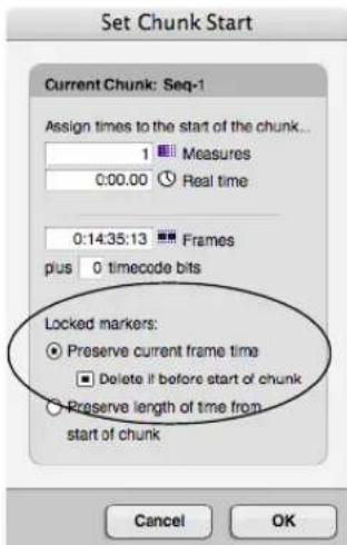
Figure 64-4: These Set Chunk Start options either preserve locked markers or shift them relative to the beginning of the sequence when changing the SMPTE time code start frame.
LOCKED MARKERS AND CHANGING METER
When the Don't move locked markers option in the Change Meter dialog (Figure 59-1 on page 749) is checked, locked markers are not moved by the change meter operation and remain anchored to their SMPTE time code frame position.
RECORDING HITS
New markers can be entered in a sequence during playback by striking a key on your MIDI controller instrument. The time location of each marker corresponds with the time in the Counter when the key is struck. This is a very useful feature for recording cue points or hits while viewing film or video.
To create markers during playback:
1 Move to the location at which you wish to start playback.
If slaved to an external master device, this step is not necessary: Digital Performer will locate automatically when you start the master.
2 Choose Record Hits from the Markers window mini-menu.
A dialog box will appear.
3 Specify whether you want the markers to be locked or unlocked.
4 Press OK to confirm your choice or Cancel to cancel it.
After you press OK, Digital Performer will start playback. If in external sync mode, the Play button will flash until the master device is started.
5 Press a key on your MIDI controller every time you wish to enter a marker.
A marker will be entered at the current time in the Counter.
6 To stop entering markers in this way, press the Stop button in the main transport controls.
Using the Auto Stop feature in the Control Panel will also stop this type of marker entry. If you are in external sync, note that stopping the master device does not take Digital Performer out of the Record Hits mode; you must press stop in Digital Performer to end recording hits.
USING MARKERS TO FIND A TEMPO
The Markers window Find Tempo mini-menu command provides advanced tempo searching capabilities. For complete details, see chapter 65, "Find Tempo" (page 781).
STREAMERS
Streamers are visual cues superimposed on a film or video screen to assist composers, conductors, directors and producers in writing, recording and producing music and soundtracks for picture.
For more details, see chapter 66, "Streamers, Punches and Flutters" (page 787).
MARKER HINTS
Below are some helpful hints for using Markers.
Composing and arranging
Markers provide a useful tool for labeling structural sections of a piece of music. The music can be recorded first and markers added afterwards or markers can be entered first to lay out the structure of the sequence before recording. In the latter case, markers can be used as a kind of musical outline for the structure of the piece.
Markers can be used to quickly rewind to the beginning of a section. They can also be used as structural place holders to mark the ends of unfinished sections.
Since markers can be cut, pasted, merged, etc., in the Conductor Track, they can be moved around with the rest of the data as a sequence grows and changes. You can move them separately from the rest of the data if you wish.
Use the View Filter to specify if markers can be affected by Edit menu commands.
If you are not working with time code, you will probably not need to display real or frame time in the Markers window.
Film and video scoring
Markers make an excellent cue sheet for planning out or displaying the structure of your score. They can show you the relationship between time locations in the film and measure locations in the music. You can then use the Find Tempo window to find the tempo that best lines up metrical beats of the sequence with important visual events. This can all be done before recording a note of music.
In addition to using markers to define the structure and tempo of your score, you may want to add markers for visual cues and hit points. The Record Hits feature is especially suited for this. These markers should be locked since their time location corresponds to a frame location. When
locked, the measure time location of the marker will be updated if you change the tempo and meter. The frame location will not change.
Markers can be an indispensable tool for triggering visual cues (streamers, punches and flutters). See “Streamers, Punches and Flutters” on page 787.
CHAPTER 65 Find Tempo
The Find Tempo feature helps you find the tempo that best matches a list of locked markers ("hits"), with as many hits as possible falling on beats.
When Find Tempo works best....781
Preparing markers....782
Opening Find Tempo....782
Entering search parameters ....782
Processing the results ....783
Browsing the tempo search results .....784
Auditioning a specific tempo ....785
Viewing the results of a specific tempo ....785
Applying the tempo to your sequence....785
Copy and move locked markers....785
Locking tracks before applying a new tempo .....786
WHEN FIND TEMPO WORKS BEST
Find Tempo works best at the beginning of the scoring process, when you've got an EDL (Edit Decision List) or hit list, before you've written any music (although you can certainly experiment with it on existing material). If you do try it with existing material, it works better with music that is already a constant tempo. Lots of existing tempo changes in the conductor track do not generally produce good results.
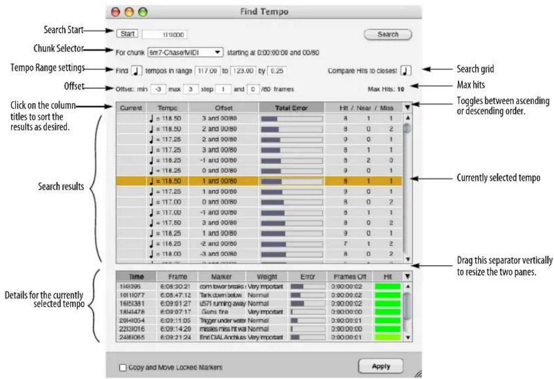
Figure 65-1: The Find Tempo window.
PREPARING MARKERS
Use the Markers window to prepare your markers for effective tempo searches. Find Tempo only searches on locked markers, so be sure to lock any markers you wish to include in the search.
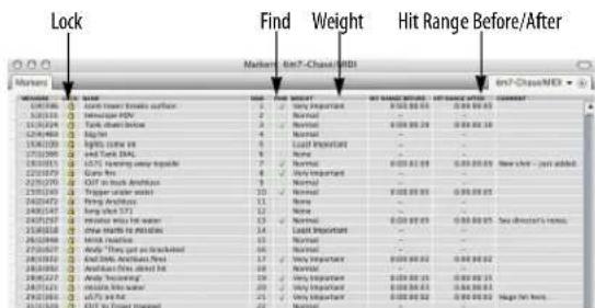
Figure 65-2: Preparing locked markers for Find Tempo.
Choosing which locked markers to include
For any locked markers you wish to include as "hits" in the search, place a check mark in the Find column next to the marker name. To check or uncheck several (or all) markers at one time, select them and use Include in Find Tempo Range and Remove from Find Tempo Range in the Markers window mini-menu. Unlocked markers cannot be checked (because they would move when the tempo changes); lock them first and then check them.
Dragging in the Lock and Find columns
In the Markers window, you can vertically drag across multiple markers in the Lock and Find columns to enable them in one gesture.
Assigning weight (importance)
You can assign a degree of importance to each marker by choosing it from the menu in the weight column. Four weight settings are provided: none, least important, normal, and very important.
Assigning a hit range
In the Hit range before and Hit range after columns, you can enter a number of SMPTE frames before and after the marker that constitutes a hit. To assign a range to several markers at one time, select them and use the Set Hit Range mini-menu command.

Figure 65-3: Setting a hit range for one or more markers.
OPENING FIND TEMPO
After you've prepared your list of locked markers, you're ready to search for tempos. To open Find Tempo, choose Find Tempo for Locked Markers from the Markers window mini-menu.
ENTERING SEARCH PARAMETERS
As shown in Figure 65-1, use the area at the top of the window to enter basic guidelines for the search.
Search Start
Use the Search Start (Figure 65-1) to enter a measure|beat|tick where you want to start the tempo search. Applied tempos will be inserted at this point in the sequence. Click the Start button as a shortcut for entering the current counter time in the start field.
Chunk Selector
The Chunk Selector (Figure 65-1) lets you choose which cue (sequence) you are searching in. It also displays the start time of the chunk to the right of the selector popup. (Time code bits are displayed as 80ths of a frame.) This chunk start time will immediately update if you choose to apply a tempo with an offset, to show you what effect the offset had on the chunk start time. Therefore, it is
not necessary to go to the Chunks window mini- menu to open the Set Chunk Start dialog to verify what happened to the chunk start time.
Tempo Range settings
The Tempo Range settings (Figure 65-1) let you choose the metric division (quarter note, eighth note, etc.), the range of tempos in which you'd like to search, and the frequency of different tempos you'd like to try within that range.
The default frequency is 0.25 of a bpm, which means that every tempo, in quarter bpm increments, will be searched within the range you specify. Smaller frequency values produce more resulting tempos and increase the chances of finding the most hits. But they also take longer. Lower frequency produces fewer tempos and shorter calculation times.
Note that the BPM (Beats Per Minute) note value for the tempo is independent of the resolution setting for the search grid setting (shown in Figure 65-1 and explained in the next section).
Search Grid
The Search Grid note value menu (Figure 65-1) lets you set the beat resolution grid on which you would like to search for hits. Because this is separate from the tempo specification, you can search, for example, for quarter note tempos but evaluate hits according to the closest eighth note.
Offset
The Offset settings (Figure 65-1) allow you to specify how much of an offset (in frames) you wish to consider from the chunk's current SMPTE start time, and how many different offsets to check. The offset settings shown in the example in Figure 65-1 would check the results of every tempo with offsets ranging between -3 and 3 frames. The Step setting specifies how many offsets to check between the minimum and maximum frame numbers. The Step setting in this example will test offsets at intervals of one and one-half frames. Therefore, the set of offsets that will be considered is -3.0, -1.5, 0, 1.5, 3.0 .
If you choose to search for tempos using a range of offsets, every offset within the range is shown in the list of results, regardless of the number of hits and misses it contains. This allows you to inspect the complete set of search results.
Search button
The Find Tempo window automatically recalculates the tempo search results whenever a search parameter changes. But if you want to manually force Digital Performer to re-calculate the tempo search results for some reason, click the Search button (Figure 65-1).
Max Hits
The Max Hits (Figure 65-1) indicator is a static text readout that tells you how many searchable markers you have (the maximum possible number of hits). This is a convenient reference for evaluating the number of hits and near hits. In this example, if you get 10 hits, you'll know that you got 10 out of 100. The Max Hits indicator counts only those markers that occur after the search start time.
PROCESSING THE RESULTS
As soon as you finish entering a new set of search parameters, an animated processing symbol appears in the upper right corner of the window to indicate that tempos are currently being searched. Find Tempo always begins searching automatically, as soon as you enter new parameters, change the existing parameters or even make changes to the locked markers in the sequence. But you can always initiate searching again by clicking the Search button.
Searching before the beginning of the sequence
If you've chosen to include a locked marker in your search that occurs at or before the sequence start frame, offsets cannot be applied. As a result, you will see a red warning message at the top of the Find Tempo dialog that warns you that a locked marker at or before the sequence start time prevents use of offsets.
BROWSING THE TEMPO SEARCH RESULTS
After a search is complete (when the processing symbol disappears), all of the tempos you specified (as prescribed by the tempo range) appear in the list, along with their Offset, total error, and their hits/near/misses count. You can sort the list in ascending or descending order by any one of these characteristics by simply clicking the title of the column. The list will immediately be resorted according to the column title you click. Use the triangle on the far right (as shown in Figure 65-1 on page 781) to toggle the list between ascending or descending order. For the sake of comparison, the sequence's current tempo is also calculated and included in the list.
The following sections provide a brief explanation of each column in the Search Results list. You can sort the list by the values displayed in each column by clicking the column title.
Current
The Current column identifies the search results entry for the current sequence tempo (either a fixed tempo or the sequence's tempo map). If the sequence is in Conductor Track tempo mode, then the current tempo displayed in this column is the average tempo for the sequence. The average tempo is shown in italic text.
Click the column title and use the ascending or descending order triangle (above the vertical scroll bar) to sort the list such that the current tempo is listed first, at the top.
Tempo
The Tempo column displays each tempo (in beats per minute) for which hits have been calculated. The number of tempos in the list is determined by the tempo range you specify, along with the frequency of tempos you've chosen to try within that range (as explained earlier in “Entering search parameters” on page 782). Click the column title and use the ascending or descending order triangle (above the vertical scroll bar) to sort the list by tempo.
Offset
The Offset column (Figure 65-1) shows you the offset (in frames and 80ths of a frame) that is associated with the tempo for this search result. A search result is the combination of a tempo and an offset. If you apply a tempo, its offset (if non-zero) will be added to the current chunk start time.
Negative offsets
Offsets can be either positive or negative, although negative offsets are limited so they can never shift the chunk start time to a value that is less than zero.
Partial frame offsets
Partial frame offsets are explicitly shown, rather than hidden (as in previous versions of Digital Performer). If you click the Tempo column heading to sort the results list by tempo, then each tempo is shown with all of its possible offsets before the next tempo is shown.
Total Error
The Total Error column gives you a bar graph representation of how well or poorly the tempo matches your hits. This measurement takes into account how close each locked marker is to the nearest beat, and then averages the total. Each marker's weight is also factored into the total error, with important markers influencing the total error score more heavily than less important ones.
Hit / Near / Miss column
The Hit/Near/Miss column (Figure 65-1) shows three numbers: the number of hits, the number of markers that are within 1 frame of being a hit, and the number of misses. This is valuable information for honing in on tempo choices, and you can conveniently compare these numbers with the total possible number of hits (Max Hits) displayed just above this column. If you click the heading of the Hits/Near/Miss column to sort the tempo results list, it orders the results first by number of hits, and secondly by number of near misses.
AUDITIONING A SPECIFIC TEMPO
If Audible Mode is on and a tempo in the list is selected, the metronome will click at that tempo. You can turn Audible Mode on or off with the speaker button in the Control Panel.
VIEWING THE RESULTS OF A SPECIFIC TEMPO
To get a closer look at the results for a certain tempo, click the tempo in the list to highlight it. When you do, the list in the lower portion of the window shows details about every marker for that tempo, including the number of frames off it falls from a beat and the total amount of error for that marker. In addition, the closeness of the hit is indicated by color in the Hit column as a general reference. Green means a direct hit; yellow means it is close, and red means there was no direct hit.
The following sections provide a brief explanation of each column in the Find window marker list. Once again, you can sort the list by the values displayed in each column by clicking the column title.
Time
This is the location of the marker in measures|beats|ticks (as entered in the Markers window).
Frame
This is the marker's SMPTE frame location (as entered in the Markers window).
Marker
This is the Marker name (as entered in the Markers window).
Weight
This is the Marker weight as specified in the Markers window. See “Preparing markers” on page 782.
Error
This is a bar graph representation of how far away the marker is from the nearest beat.
Frames off
This column tells you how many frames the marker is from the nearest beat.
Hit
This column gives you a visual indication of how close the marker is to a hit (beat). Green is a good hit (near the center of the marker's hit range). Yellow is a near miss; red is a complete miss.
APPLYING THE TEMPO TO YOUR SEQUENCE
The Apply button writes the currently selected tempo to the sequence specified at the top of the Find Tempo window, starting at the Start Search location (Figure 65-1 on page 781).
COPY AND MOVE LOCKED MARKERS
The Copy and move locked markers option helps you if you are finding a tempo after you have written music. It creates an unlocked copy of each locked marker so that when you apply your tempo, the unlocked markers shift with the music, allowing you to see where your music data has moved after applying the tempo.
LOCKING TRACKS BEFORE APPLYING A NEW TEMPO
If you have data that you don't want to move when applying a tempo to a sequence, then lock that track before applying the tempo.
CHAPTER 66 Streamers, Punches and Flutters
OVERVIEW
Streamers, flutters and punches are visual cues superimposed on a film or video screen to assist composers, conductors, directors and producers in writing, recording and producing music and soundtracks for picture.
Digital Performer can superimpose streamers, punches and flutters as follows:
- On Digital Performer's Movie window viewed on your computer screen
- On an external SD or HD video monitor displaying DP's Movie window output through a hardware converter, with visual cues being composited “on the fly” and combined with the movie video.
- On an external NTSC or PAL video monitor connected to a Video Timepiece, Digital Timepiece, ProCue 1m1, or ClickStreamMachine. The video signal on which the film scoring cues are overlaid can be from any source, including Movie output from Digital Performer. In this scenario, the visual cues are generated by the ProCue 1m1 or other device.
■ On an exported movie.
Streamers ....787
Punches....787
Flutters....787
Video output from Digital Performer ....787
Supported film cue hardware....788
Setting up the VTP or DTP ....788
Setting up the ProCue 1m1 or ClickStreamMachine ....788
Activating streamers, punches and flutters .....789
Working with marker streamers ....790
Visual cue events in the Conductor track....792
Exporting visual cues....792
STREAMERS
A streamer is a colored vertical bar that travels across the screen from left to right. The time that it takes from its entrance on the left to its exit on the right can be specified, and there are several industry standard durations. The streamer is triggered such that it reaches the right-hand side of the screen at a visual hit, a point of interest in the visual material chosen as a reference. The streamer is usually then followed by a punch on the exact hit.
PUNCHES
A punch is a circle that flashes on-screen — usually for just one film or video frame — exactly at a hit point to emphasize the hit. Before the use of video and digital technology in scoring sessions, when celluloid work prints were still in use, streamers were created by scraping the emulsion off of the surface of consecutive film frames. Punches were created by actually punching a hole in the appropriate film frame.
FLUTTERS
A flutter is a sequence of 3, 5 or 7 punched frames each separated by an unpunched frame. The result is a flickering set of punches. Flutters are often used to mark the downbeats of measures. Flutters have an anchor frame, which corresponds to the exact frame location of the flutter event.
VIDEO OUTPUT FROM DIGITAL PERFORMER
Digital Performer can display streamers, flutters and punches in its Movie window. You can view them on your computer screen or secondary monitor in full-screen mode. You can also view them on an external SD or HD video monitor through a FireWire video converter or a MOTU
video interface such as the HDX-SDI. Visual cues are composited "on the fly" and combined with the movie video. No pre-rendering is necessary.
To enable the display of streamers, flutters and punches on live video output, enable the Movie Overlay option (Figure 66-3). For complete information about the Movie window, see chapter 32, "Movie Window" (page 311).
SUPPORTED FILM CUE HARDWARE
Digital Performer supports several hardware devices that can generate streamers, flutters and punches over a video input signal:
Manufacturer Web site Device
| MOTU www.motu.com Digital Timepiece | |
| MOTU www.motu.com Video Timepiece | |
| CueLine www.cueline.com ProCue 1m1 | |
| ClickStreamMachine www.clickstreammachine.com | ClickStreamMachine |
SETTING UP THE VTP OR DTP
For information about setting up the Video Timepiece or Digital Timepiece to generate streamers, consult the Digital Timepiece or Video Timepiece manual. Essentially, all you need to do is add it to your your MIDI device configuration (Setup menu > Bundles > MIDI Devices tab) and make sure its MIDI connections are working properly.
SETTING UP THE PROCUE 1M1 OR CLICKSTREAMMACHINE
Add the ProCue 1m1 or ClickStreamMachine to your MIDI device configuration (Setup menu > Bundles > MIDI Devices tab) and make sure it is connected to your MIDI interface as demonstrated below for the 1m1:

flowchart
graph TD
A["Micro Express USB"] -->|1 2 3 4 5 6| B["K2600"]
A -->|1 2 3 4 5 6| C["ProCue 1M1"]
Figure 66-1: Adding the ProCue 1m1 or ClickStreamMachine to your MIDI device configuration.
Make sure that the video deck or other video source feeding the 1m1 or ClickStreamMachine is synchronized with Digital Performer. In the example below, a MOTU MIDI Timepiece AV is being used to synchronize Digital Performer to the video deck via SMPTE time code from the video:

flowchart
graph TD
A["Computer running Digital Performer"] -->|USB connection bearing MIDI time code and MMC transport commands| B["Audio cables bearing SMPTE time code"]
B --> C["video deck"]
C -->|MIDI| D["video signal"]
D --> E["video signal with streamers and punches"]
E --> F["video monitor"]
C --> G["ProCue 1m1, ClickStreamMachine or Digital Timepiece"]
Figure 66-2: ProCue 1m1 synchronization and video connections.
ACTIVATING STREAMERS, PUNCHES AND FLUTTERS
After you have made the preparations described in the previous sections for the Movie window or the film cue hardware you are using, you are ready to generate streamers, punches and flutters in Digital Performer. There are numerous ways to do so, but first, to activate them globally, choose Preferences from the Digital Performer menu (macOS) or Edit menu (Windows) and click the Film Scoring Events item as shown in Figure 66-3.
Enable the check boxes for the types of visual events you would like to use, as well as the output devices on which you would like to view them. Checking the boxes in the left-hand column activates the features for each type of visual event globally in the program. The settings on the right-hand side determine the default appearance for each type of visual event when it is first created, although in most cases you can customize each individual event (to override these default settings) as desired.
Marker streamers
Marker streamers (Figure 66-3) are streamers associated with — and triggered by — a specific marker. When playback approaches the marker, a streamer is generated of the specified duration to hit the right side of the video monitor exactly at the marker's frame location, optionally accompanied by a punch.
Stand-alone streamers
A stand-alone streamer (Figure 66-3) — or streamer event — is a special streamer event that you can insert in the Conductor Track, independent of markers or any other events. It functions identically to a marker streamer but gives you the added flexibility of not being associated with a marker.
Punch and flutter events
Punch and flutter events are similar to streamer events: they can be inserted in the Conductor Track, independent of markers or any other events.
The Digital Timepiece and Video Time Piece cannot produce flutters or punches that are independent of streamers.
New Markers have a streamer
When checked, the New Markers have a Streamer option (Figure 66-3) causes newly added markers to have a streamer enabled for them (according to the default settings).
Default settings
In the right-hand column (Figure 66-3), choose the default color, duration and size for marker streamers, streamer events, punch events and flutter events. This is the color, duration and size that will be used for each type of event, unless you specify otherwise to override these default settings for an individual event, as explained later.
WORKING WITH MARKER STREAMERS
Choose Show Streamers from the Markers window mini-menu to show or hide the Streamers column. To enable a streamer for a marker, choose the desired duration from the streamer column next to the marker. To temporarily disable the streamer at any time, click the streamer icon in the left-
hand portion of the streamer column. You can also drag across multiple streamer icons to toggle them, and you can Option/Alt-click and Command/Ctrl-click them in the same fashion as in the Lock column.
![MEASURE 1[4]396 5[3]131 11[3]224 12[4]469 15[4]109 17[1]366 19[1]015 22[2]079 22[5]270 23[5]243 24[2]472 STREAMER 2 sec 2.67 sec 3.33 sec 2 sec NAME conn tower breaks surface telescope POV Tank down below big hit lights come on end Tank DIAL u$71 running away topside Guns fire CUT to back Anchlass Trigger under water firing Anchlass](/content/2026/05/834832/images/6d94c55646da0e2a8c6a81d0195b3b9b27732c4118a7b7676f8435cc853ac71c.jpg)
Figure 66-4: Marker streamers.
Marker streamer options
Select one or more markers and choose Set Streamer Options from the Markers window mini-menu to open the Streamer Options:
Figure 66-3: Preferences for streamers, punches & flutters.


Figure 66-5: Streamer options.
The Streamer options window (Figure 66-5) lets you override the default marker streamer settings made in the preferences window (Figure 66-3). The settings are the same: they let you choose the output device for the streamer, as well as the color, duration, punch color and punch size.
Accessing streamer options when adding a marker
If you would like to access the streamer options (Figure 66-5) when adding a new marker, choose New Marker with Options from the Markers window mini-menu. Doing so opens the streamer options, where you can name the marker and choose the desired options. When you click OK, the marker is added at the current counter location.
3-second streamers and the Pro Cue 1m1
The Pro Cue 1m1 does not support 3-second streamers. Choose 3.33 seconds instead. If you choose to output a streamer of length 3 seconds to the ProCue 1m1, no streamer is displayed.
Generating a marker streamer track for standard MIDI file export
The Generate Streamer track for command in the Markers window mini-menu allows you to generate a MIDI track that contains all the MIDI needed to generate your marker streamers on either a Digital Timepiece, Video Timepiece, a ProCue 1ml, or a ClickStreamMachine. However, you do not have to create this MIDI track in order to make your marker streamers appear. Digital Performer will automatically generate MIDI to produce your marker streamers on the selected outputs, whether or not a MIDI track has been generated.
The track generation feature is meant to make it easier for you to export your Digital Performer streamer project to other music programs. In fact, generation of the track does not stop the automatic output of MIDI during playback that happens whenever a film event is assigned to play to a given external box. If you assign the generated streamer track to output to the same box, then you'll be sending each MIDI message twice to the hardware: once automatically, and once from the generated track. To cease the automatic transmission of MIDI data to the box, you must either turn off the global generation of streamers, punches and/or flutters in the Film Scoring Events preferences pane, or turn off the output assignment for that box on each film scoring event in the sequence.
Choose Generate Streamer Track for from the Markers window mini-menu and choose the desired streamer hardware from the sub-menu to create a new MIDI track that contains all of the MIDI data necessary to precisely reproduce the marker streamers you've programmed in Digital Performer. After you've generated the streamer track, you can export your entire sequence as a
standard MIDI file and then play it back from any other MIDI sequencer to trigger the streamers as originally programmed in Digital Performer.
You can also use this feature to directly edit the MIDI data that triggers the streamers for your streamer hardware.
VISUAL CUE EVENTS IN THE CONDUCTOR TRACK
If you would like to create streamer events that are not associated with a marker, or if you would like to create independent punch or flutter events, you can insert them and edit them by hand in the Conductor track. Double-click the event to access its settings. For further information, see “Types of Conductor track events” on page 733.

Figure 66-6: Inserting streamer, punch and flutter events in the Conductor track.
EXPORTING VISUAL CUES
When running under macOS 10.7 or later, Film Scoring Events can be included when you Bounce to Disk using QuickTime Movie Export (“Bouncing to a Movie” on page 966). They become a permanent part of the exported movie and can be played back via any QuickTime compatible video player, Windows Media Player, or Digital Performer’s hardware video output features, as described in “External video hardware output” on page 315.
To do so, make sure they are enabled in Digital Performer's preferences as explained in "Activating streamers, punches and flutters" on
page 789, and then enable the Include film scoring events option in the QuickTime Export Options window (which appears during the export process). All currently visible (enabled) streamers, punches and flutters will be included in the resulting movie file. This includes the visual click, if enabled. Note that they must be enabled in the preferences and assigned to the QuickTime movie overlay to be included in the bounce. If not, this check box has no effect and they will not be included in the bounce.
CHAPTER 67 Chunks Window
OVERVIEW
The Chunks window displays the chunks in a Digital Performer file. A chunk is either a sequence (a collection of tracks), a song (a collection of sequences and other songs) or a V-Rack™ (a collection of instrument tracks, aux tracks and/or master faders). A Digital Performer file can contain as many chunks as memory in your computer will allow. Sequence and song chunks can be cued for playback, either automatically or manually, in order or at random. You can also build an entire song out of other sequences and songs by chaining and stacking chunks in the Song window, which provides seamless, simultaneous playback of chunks in any order and combination.
V-Racks have no disk tracks and therefore do not "play back" in the same sense as sequences or songs. Instead, they serve as a virtual "effects rack" that can also contain virtual instruments. These effect and instrument plug-ins can be accessed by any audio and/or MIDI track in the currently play-enabled sequence or song.
Chunks window Quick Reference .....793
Chunks window basics ....795
The Chunk Control buttons....800
CHUNKS WINDOW QUICK REFERENCE

Figure 67-1: The Chunks window lists sequences, songs and V-Racks (categorically referred to as "chunks") in the Digital Performer project.
Type: Displays each chunk's type by icon. This icon is used to drag chunks into Song windows and to change the order of chunks in the Chunks window.


Figure 67-2: The sequence, song and V-Rack icons.
Play: Shows the play-enable button for each chunk. When a chunk's play-enable button is blue, the chunk is play-enabled. Only one sequence or song chunk can be play-enabled at a time. V-Racks, on the other hand, display a blue dot to indicate that they are active and available at any time. Click their play-enable dot at any time to bring them on line or to take them off line.
S# (Song Select Number): Displays the song select number that will play-enable the chunk when received from a MIDI controller. Song select numbers range from 0-127. If a chunk has no song number assigned, the column displays a single
dash (-). V-Racks do not have a song select number because they do not have disk tracks that play back in the conventional sense.
If Digital Performer receives a song select number that is assigned to two or more chunks, Digital Performer will cue the chunk that appears highest in the list. For this reason, it is best to assign a unique Song Select number to each chunk.
End time: Displays each chunk's End time. In automatic mode, End time is the downbeat of the measure following the last complete measure in the chunk. When a chunk's End time is in manual mode, it is bold and can be edited to be any length. V-Racks do not have an end time because they hold no audio or MIDI data.
Name: Displays the name of the chunk. Click the name to select the chunk. Option/Alt-click the name to change it. Double-click the name to open the Tracks, Song or Mixer window belonging to the chunk.
Because chunks can be imported into other files, dragged without limit into Song windows, and duplicated easily, use the most descriptive chunk name possible to avoid confusion.
Color: The Color column lets you color-code chunks using the standard color picker.
Comments: Displays as much as possible of your comments for each chunk. View and edit the comments by clicking them.
Next/Previous Chunk buttons: If you have more than one sequence or song in the file, these buttons skip to the next or previous one, much like the skip buttons on a CD player.
Cue Chunks button: When highlighted, it play-enables the next chunk in the chunks list after the current playback chunk reaches its End time and stops. To begin playback of the next chunk, press the Play button, or a command for the Play button.

Chain Chunks button: When highlighted, starts playback of the next chunk in the list after the current chunk reaches its End time.

Search: If you have a lot of chunks in the list, type in the name of the one you are searching for.
The Chunks window mini-menu
The Chunks window mini-menu contains the following commands:
New Sequence: Creates a new sequence. To create several sequences at once, press the Option/Alt key while choosing New Sequence.
New V-Rack: Creates a new V-Rack. To create several V-Racks at once, press the Option/Alt key while choosing New V-Rack.
New Song: Adds a song to the chunk list. To create several songs at once, press the Option/Alt key while choosing New Song.
Duplicate Track Layout: Creates a new, empty sequence with the same track layout as the selected sequence. Select an existing sequence before choosing this command.
Duplicate Sequence: Creates an exact copy of the currently selected sequence.
Open Chunks: Opens a Song window for each highlighted song, a Tracks window for each highlighted sequence, and a Mixing Board for each highlighted V-Rack.
Auto/manual end time: Toggles the Auto/manual status of the selected chunks. Automatic mode locks the chunk's End time at the downbeat
of the measure following the last complete measure in the chunk. Manual mode changes the time to boldface and allows it to be edited.
Set Chunk Start: Establishes the start times of the currently selected chunks in three of Digital Performer's time formats: measures, real time, and SMPTE time. The start times are what you see in the Counter when you rewind back to the beginning of the chunk. This is the same window that appears when you click the Start Time button in the main counter.
Delete: Deletes the selected chunks. If you attempt to delete a chunk that is part of a song in the open file, a dialog box appears, prompting you to confirm your decision.
CHUNKS WINDOW BASICS
The Chunks window lists the chunks in a file and provides useful features to manage them, such as adding, deleting, and other operations. In addition, chunks can be dragged from the chunks window into a Song window to build a song. For more information, see chapter 69, “Songs” (page 809). Chunks can also be automatically cued to playback in the order in which they are listed in the Chunks window. For more information about cuing, see “Saving Memory and Auto-Record Times” on page 212. Chunks can also be cued remotely from your MIDI controller. For more information, refer to chapter 9, “Commands” (page 105).
Opening the Chunks window
To open the Chunks window, choose Chunks from the Project menu. The Chunks window will appear, displaying a list of all sequences and songs in the open file.
Selecting Chunks
There are several methods of selecting chunks:
To select a single chunk, click on its name. The name will highlight.
To select several adjacent chunks, click a chunk name and drag over the desired names. All chunks dragged over will highlight.
To select several non-adjacent chunks, hold down the Command/Ctrl key and click on the names of the chunks you wish to select. They will highlight.
To deselect chunks when more than one are highlighted, hold down the Command/Ctrl key and click on the chunks you wish to deselect. They will unhighlight.
Creating new chunks
To create a new, empty chunk, choose New Sequence, New Song or New V-Rack from the Chunks window mini-menu. To add several at once, hold down the Option/Alt key while choosing Add. You will be prompted for the number of chunks to add.
To create a new chunk with the same track layout as an existing Chunk, highlight the existing chunk and select Duplicate Track Layout from the Chunks window mini-menu. A new chunk will be added with the same name as the chunk you highlighted, appended by the word "copy". It will have the same track layout as the original: the number of tracks, the track names, and the track output assignment will be identical to the original.
Duplicating existing chunks
Sometimes you may want to duplicate a chunk to experiment with changes or for some other reason. To duplicate a chunk:
1 Highlight the chunk name in the Chunks list.
2 Choose Duplicate Sequence from the Chunks window mini-menu.
An exact copy of the sequence, including all the data in the tracks, will be placed at the end of the list in the Chunks window. Rename it immediately so that you do not get the copy and the original mixed up.
Loading Chunks from another file
Digital Performer's Load command allows you to quickly import Chunks into an open file from another, unopened Digital Performer file.
For step-by-step instructions to load Chunks, see "Loading a sequence, song or V-Rack" on page 29.
Copying and pasting Chunks between projects
You can copy and paste the following items between projects:
■ Entire sequences, songs and/or V-Racks that have been selected in the Chunks window
■ Song window selections (sequences and/or songs that have been selected in an Song window)
When copying and pasting sequences and songs, all soundbites and sequences used in them are also copied and pasted into the destination project.
Splitting up an existing sequence into separate chunks
The Copy selection to new sequence command in the Control Panel sequence menu takes the current selection in the current window and turns it into its own sequence Chunk in the Chunks List window.
The Copy to new sequence command makes it easy to break up a sequence into separate pieces (Chunks) in order to rearrange them more freely in a Song window. For example, let's say that you have built several phrases that are a few measures long in a Sequence. But now you want to rearrange them and try different combinations. To do so, you can make any selection and choose Copy to new sequence from the mini-menu for each one. Then, you can drag the resulting sequence Chunks from the Chunks list window into an empty Song window to try different orders and combinations.
After you have arranged the Song as you like, you can even convert it back into a sequence using the Song window mini-menu command called Merge Chunks to Sequence. This command takes the separate Chunks inside the Song window and reduces them to a single sequence Chunk.
At any time, you can take your music freely back and forth from Sequence form to Song form with these two commands to help you create your music.
To create a sequence Chunk from the Track Overview window:
1 Make any selection that you wish.
2 Choose Copy Selection to New Sequence from the Tracks window sequence menu.
A dialog box appears.

3 Type in a name for the sequence.
4 Type in an End Time to determine the length of the sequence.
By default, the end time is determined by the length of the selection.
5 (Optional) Type in any other information you wish.
6 Press OK to confirm your choice or Cancel to withdraw the command.
Deleting chunks
To delete a chunk, click its name to highlight it and choose Delete from the Chunks window mini-menu. To delete several chunks at once, highlight the name of each one as described in the Selecting Chunks section above. You can Undo this command.
Choosing the current playback sequence or song
At any given time, one sequence or song is designated for playback, and it is the only one you can play and record into. Certain functions, such as recording, are available only to the currently play-enabled sequence or song. For example, if a sequence is play-enabled, its Tracks window has record-enable buttons by its tracks. If a song is play-enabled, one of its component sequences can be record-enabled. Only that sequence's Tracks window will have record-enable buttons.
V-Racks, on the other hand, are always play-enabled, making their tracks available at all times to the currently play-enabled sequence or song.
You may edit any sequence or song in the file at any time regardless of whether it is play-enabled or not.
To play-enable a sequence or song:
- Click the play-enable button to the left of its name. It will turn blue. The play-enable buttons of the other sequences and songs will be gray.
OR
- Click the Next/Previous Chunk buttons as needed until the sequence or song's name is displayed in the Control Panel
OR
■ Select the sequence or song from the Sequence menu in the Control Panel (Figure 22-26 on page 213)
Play-enabling by remote control
Digital Performer also provides two different methods of play-enabling chunks from a remote device.
Chunk Selection commands
The first method is with the Chunk select Commands found in the Commands window, where each Chunk is assigned a computer key binding and MIDI event. You play-enable a Chunk by pressing its corresponding computer key binding or sending its corresponding MIDI event from your MIDI keyboard (or controller). Please refer to chapter 9, “Commands” (page 105) for more information.
Song Select messages
The second method is Chunk Select, which allows you to cue chunks for playback by sending a MIDI Song Select message from a MIDI controller. The Chunks window column S# displays the Song Select number that, when received, will cue the corresponding chunk for playback. If a chunk has no Song number assigned, the S# column displays a single dash (-).
Most hardware sequencers and some MIDI keyboard controllers can send and receive Song Select messages. Simply send a Song Select message as instructed in that module's documentation. If the open file contains a chunk assigned to the Song number in the message, that chunk will be play-enabled. If more than one chunk has the same Song number assigned, the one highest in the chunks list will be cued.
When used in combination with the Chunk Chaining buttons in the Chunks window, a Song Select message cues the corresponding chunk to be play-enabled or played back.
Opening chunks
Each sequence chunk can have its own Tracks window, and each song chunk has its own Song window. To see a chunk's Tracks or Song window, click the chunk's name to highlight it and choose Open Chunks from the Chunk window mini-menu. Or just double-click the chunk name.
Rearranging the order of chunks
You may rearrange the Chunks in whatever order is most meaningful to you. To change the position of a Chunk in the Chunks list:
1 Press the type icon of the Chunk you want to move.
The cursor changes into that chunk icon.
2 Drag and drop the mouse to the position where you want the Chunk.
If you wish to move two or more Chunks at once:
1 Shift-click or Command/Ctrl-click their names to select them.
2 Grab the type icon of one of them.
3 Drag and drop to the position in the list where you want them.
Rearranging the order of the Chunks is a useful organizational tool. In addition, it lets you determine the Chunks' default cueing order when using the Next/Previous Chunk, Cue Chunks, and Chain Chunks buttons described later in this chapter.
Changing the name of a chunk
To change the name of a Chunk:
1 Option/Alt-click the name of the chunk.
A small box will pop up.
2 Type the chunk name in the box.
3 Press the Return key or click outside the box to confirm the name or Command/Ctrl-period to cancel it.
You can use the Enter or Down Arrow key to approve the change and edit the next chunk name in the list. You can also use the Up Arrow key to approve the change and edit the previous chunk name in the list.
Entering comments
To enter or modify comments for a chunk:
1 Click in the comments field to the right of the chunk name.
A box appears. If you've already entered a comment for the chunk, the entire comment appears highlighted in the box.
2 Enter or edit the comment.
3 Click OK to confirm the changes you've made and close the comments box, or click Cancel to discard the changes.
Press the Down Arrow key or the Enter key to approve the changes you've made and move to the comment for the next Chunk. The Up Arrow key likewise moves to the comment for the previous Chunk.
When entering or editing a comment, the Return key starts a new line of text instead of approving the changes as usual in Digital Performer's user interface.
Auto versus manual end time
The Chunks window field End Time displays either the automatic, Digital Performer-generated ending time of the Chunk, or a time that you have entered manually. It's important to understand how this time affects your music.
Digital Performer offers two ways of playing Chunks sequentially: by arranging Chunks vertically and horizontally in the Song window, and by Chunk Chaining using the Cue Chunks, Chain Chunks, and Next/Previous Chunk buttons in the Chunks window. The End time shown for each Chunk in the Chunks window affects these two types of chaining differently.
When a Chunk is in a Song window, the Chunks window End time does not affect the playback length of the Chunk. Within a song, a Chunk will play every note it contains, regardless of its Chunks window End time. What it does affect is column placement. Columns appear automatically at the End time of each Chunk dragged into the Song window. This makes it easy to place Chunks end to end.
For example, a Chunk whose last attack is at 4|4|322 will have an automatic End time of 5|1|000. When this Chunk is dragged into a Song window at time 1|1|000, a column will appear at 5|1|000, making it very easy for you to place the next Chunk in a metrically logical location. If you prefer a five measure phrase, just change the End time to 6|1|000. The end column will appear at 6|1|000, even though the Chunk only plays through four measures.
Again, remember that the Chunk End time does not affect playback in the Song window, only the column placement.
When using the Chunk controls in the Chunks window, you'll find that each Chunk's End time does affect its playback length. For example, clicking Play with the Chain Chunks button enabled causes playback of one Chunk after another, each Chunk playing until the counter reaches that Chunk's End time. Phrases, even notes that normally would last through the End time will be cut off. You can avoid this by setting a Chunk's End time to be later, thereby building sustain into the Chunk's play length.
In summary: regardless of auto/manual status, in the Song window the End time determines the Chunk's ending column location but not its playback length. During Chunk Chaining, playback actually stops at the End time.
For more information about the Song window and Chunk cuing, see chapter 69, “Songs” (page 809) and “Saving Memory and Auto-Record Times” on page 212, respectively.
Building a song with chunks
To build a Song out of Chunks in the Chunks window, drag their type icon into a Song Window (Figure 67-3 on page 800). For complete information, please refer to the next chapter, "Songs".
Copying tracks from one sequence chunk to another
Use the following procedure to copy between sequences that have the same track layout (i.e. the same number of tracks, preferably with the same MIDI channel assignments). If the sequences have different track layouts, this procedure will not work correctly. See chapter 20, “Tracks Window” (page 169) for more information.
To copy from sequence A and paste into sequence B:
1 Activate the Tracks window and choose Sequence A from the Sequence menu.
2 Set the start and end times in the Selection Information window to define the region you wish to copy.
To select the entire sequence, choose Set to Chunk Bounds from the Set To menu.
3 Highlight all the track names in Sequence A.
Either click and drag over them, or choose Select All from the Edit menu.
4 Select Copy from the Edit menu.
As a short cut, press Command/Ctrl-C.
5 Choose Sequence B from the Sequence menu.
6 Cue the main counter to the measure at which you want to paste the material into sequence B.
7 Select Paste from the Edit menu.
The information from Sequence A is pasted into Sequence B at the measure location you chose.
THE CHUNK CONTROL BUTTONS
The Next Chunk and Previous Chunk buttons play-enable the next or previous Chunk (sequence or song) listed in the Chunks window. The Cue Chunks button play-enables the next Chunk in the list after the current Chunk plays to its end time and stops. The Chain Chunks button causes the next Chunk in the list to automatically begin playing when the current Chunk finishes playback.
Chaining using the Chunks window
The Chunk cueing buttons in the Chunks window allow automatic and real-time cueing of Chunks, and automatic playback of cued Chunks. The Cue Chunks, Chain Chunks, and Next Chunk, and Previous Chunk buttons let you play Chunks from the Chunks window, moving up or down the list at your command.
Chunk cueing does not yield seamless transitions between Chunks. Use them for cueing situations where a pause between Chunks — either brief or indefinite — is acceptable or preferred.
For example, the Chunk Control buttons are perfect for live performance. Before a set, you could organize the Chunks list in the order you

Figure 67-3: Building a song out of sequences.
wish for the set. Then, before you begin, you could enable the Wait button. To begin the set, you simply press play. When the first song ends, the next song automatically cues up, and you can trigger it at your leisure from your MIDI keyboard. Or, without the Wait button, you can have Digital Performer go right into the next song without waiting.
It is also possible to cue and play Chunks remotely from your MIDI controller. For more information, see chapter 9, “Commands” (page 105).
When the Cue Chunks or Chain Chunks button is enabled, the Stop time displayed in the Memory Bar indicates the measure time at which the current Chunk will stop playing and the next Chunk will be cued. This time appears automatically when a Chunk is cued; it corresponds to the Chunk's End time in the Chunks window.
You can edit the Memory Bar time by clicking it, but this change lasts only until the next Chunk is enabled. If you wish a different End time to appear in the Memory Bar automatically for a particular Chunk, edit the End time in the Chunks window. Simply click the Chunk name and choose Auto/manual end time from the Chunks window mini-menu. The time becomes bold and editable. Remember that the End time only affects a sequence's playback length when using the Chunk control buttons, not when the Chunk is played as part of a song.
The Cue Chunks button
The Cue Chunks button, when highlighted, play-enables the next chunk in the Chunks list after the current playback chunk reaches its end time and stops.

Figure 67-4: The Cue Chunks button makes Digital Performer play-enable the next sequence or song in the Chunks window when it reaches the end of the current one.
To begin playback of the next chunk, press the Play button, or a command for the Play button.
The Chain Chunks button
The Chain Chunks button, when highlighted, starts playback of the next Chunk in the list after the current playback Chunk reaches its End time. This is a simple way of automatically chaining Chunks in their Chunks list order.

Figure 67-5: The Chain Chunks button makes Digital Performer cue up and start playing the next sequence or song in the Chunks window when it reaches the end of the current one.
Chaining with this button does not yield seamless transitions between Chunks. Use it for cuing situations where a brief pause between Chunks is acceptable or preferred. For seamless chaining, assemble Chunks in a Song window. For more information, see chapter 69, “Songs” (page 809).
Viewing the Chunk End Time
When the Cue Chunks or Chain Chunks button is highlighted, the end time of the sequence is graphically displayed as a final barline in the time ruler of the Track Overview or any graphic editor.
The Next Chunk and Previous Chunk buttons
The Next/Previous Chunk buttons enable the next or previous Chunk for playback. Clicking these buttons is similar to pressing the skip buttons on a typical audio compact disc player: Digital Performer stops playback of the current Chunk and starts playback of the next or previous Chunk. Chaining Chunks in this manner does not yield
seamless transitions between Chunks. To chain Chunks seamlessly, chain them inside a song as described in chapter 69, “Songs” (page 809).
Figure 67-6: When you have multiple sequences in Digital Performer file, the Skip buttons work like the skip buttons on a CD player: the play-enable the next or previous sequence or song in the project.
CHAPTER 68 V-Racks
OVERVIEW
V-Racks™ (virtual racks) are similar to sequences, except that they have no time domain and they do not hold track data or automation. The only types of tracks that you can add to them are Instrument tracks, aux tracks and master faders. As such, they are intended to be used as “effects” racks, a centralized location for effects processing and virtual instruments.
V-Racks can be created and managed in the Chunks window. See chapter 67, “Chunks Window” (page 793).
V-Rack basics....803
Creating a V-Rack....804
V-Rack quick reference .....804
Working with a V-Rack....804
V-RACK BASICS
V-Racks ™ (virtual racks) are similar to regular sequences, but they are streamlined as follows:
■ They have no time domain.
■ They do not hold track data or automation.
■ The only types of tracks that you can add are: Instrument tracks, aux tracks and master faders.
■ They do not have a Tracks Window, Sequence Editor or any other type of edit window. The only window that can be opened to modify them is the Mixing Board.
■ They cannot be placed in a song.
V-Racks have several significant characteristics that makes them very useful:
■ They are always active, regardless of what sequence or song is play-enabled.
■ Their track inputs and outputs are always available to all other sequences in the project.
■ They provide all of the real-time processing capabilities of a regular sequence, including the ability to host virtual instruments.
A virtual effects and instrument rack
When you add up all of the above characteristics, essentially what you have is a virtual effects and instrument rack — hence the name V-Rack. V-Racks are ideal in situations where you are using multiple sequences in a project, as the following examples illustrate.
Virtual instruments
A very common situation is as follows: you have a project with multiple sequences that are all playing the same virtual instrument. For example, you might be working on a TV commercial with several sequences in the project: a :15 second version, a :30 second version and a :60 second version. But they are all playing essentially the same sounds loaded into MachFive. To work most efficiently, you can create one instance of MachFive in a V-Rack, and then access MachFive from any of the other sequences, just as if it were instantiated in each sequence individually. By instantiating it only once in the V-Rack, you save memory and computer processing resources. Samples and patches will not need to reload when switching among sequences.
Mastering
Another very common situation is this: you have multiple sequences that you want to master using the same mastering effects chain. To ensure consistency and to maximize efficiency, you can add a master fader track to a V-Rack, apply the desired effects processing and then run the master
output of each individual sequence into the master fader in the V-Rack. Regardless of which sequence is play enabled, the V-Rack master fader settings can be applied. Not only do you conserve your computer's processing resources (since you only have to create one instance of the effects), you also ensure that each individual sequence is processed with exactly the same plug-in settings in your mastering chain.
Effects loops
A another common situation is this: you have multiple sequences and you wish to use the same effect in all of them as a send/return loop. For example, suppose all your sequences contain voice-overs that you would like to process through identical compression and reverb. To once again ensure consistency and simplify the setup of this loop across all sequences, you can add an aux track to the V-Rack and then add the desired effects chain plug-ins to it. Set the input to be a bus, and its output to be the main outs (or another bus, for added flexibility). Now, all tracks in any sequence assigned to that effect bus will receive identical effect processing.
Live effects processing
A final example for V-Racks is this: you are performing music in a live context, and you would like to have an effects chain set up that is always active, regardless of what sequence is playing back. You could set up an aux track in a V-Rack from a physical input on your audio hardware to a physical output, and add whatever processing you would like. Now Digital Performer can perform as a virtual effects rack, no matter which sequence is play enabled.
CREATING A V-RACK
You can add any number of V-Racks to a Digital Performer project in any of the following ways:
■ Choose Project menu>Sequences>New V-Rack
- Choose New V-Rack from the Chunks window mini-menu.
- Choose New V-Rack from the Sequences mini-menu in the Control Panel, Tracks Overview or Sequence Editor.
- Choose V-Rack Edit from the Mixing Board or the Effects window mini-menu. If a V-Rack does not yet exist in your project, one is added.

Figure 68-1: A V-Rack.
V-RACK QUICK REFERENCE
Move handle: Drag this handle vertically to change its position in the list. Note: unlike track sequences and song, you cannot place a V-Rack into a song, or drag it anywhere else. This handle is for repositioning it in the list only.
Enable/Disable: Brings the V-Rack on line (active and processing audio) or offline (inactive).
WORKING WITH A V-RACK
V-Racks are viewed via the Mixing Board. Open the Mixing Board for the V-Rack using any of the standard techniques for accessing the Mixing Board for a sequence.
For example, in the Consolidated Window, go to the Mixing Board and then choose the desired V-Rack from the Window Target menu, as demonstrated below:

Figure 68-2: Accessing the V-Rack in the Mixing Board.
For your convenience, in the Commands window (Setup menu), there is a command called V-Rack Edit that switches the Mixing Board between the sequence and V-Rack that were last viewed in the Mixing Board. The default keyboard shortcut is Command/Ctrl-Shift-V.
Adding tracks to a V-Rack
After you have opened the Mixing Board for the V-Rack (and it is the active window or cell), you can then add aux tracks, instrument tracks and master faders to it using any of the standard techniques for adding tracks to a sequence. For example, you could choose Project menu> Add Track.
Moving tracks from a sequence to a V-Rack
If you would like to move an aux track, master fader or instrument track from a regular sequence to a V-Rack:
1 Make sure the source sequence is play-enabled.
2 Select the tracks you wish to move.
3 Choose Move Selected Tracks to V-Rack from the Sequence menu in the Control Panel (as shown below in Figure 68-3), Tracks Window or Sequence Editor.

Figure 68-3: Copying a track from a sequence to a V-Rack.
4 Choose the desired destination V-Rack from the resulting dialog.
The track disappears from the source sequence and is moved to the destination V-Rack.
Deleting tracks from a V-Rack
To delete tracks from a V-Rack, choose Delete Track from the pop-up menu at the bottom of each channel strip in the Mixing Board.

Figure 68-4: Deleting tracks from a V-Rack.
The V-Rack button
The V-Rack (V) button in the lower left corner of the Mixing Board window toggles between the last-viewed sequence and the last-viewed V-Rack.

Figure 68-5: The V-Rack button
Displaying V-Racks alongside a sequence
To display V-Racks alongside your sequence tracks in the Mixing Board, use the "Show V-Racks" option in the Mixing Board mini-menu.
When enabled, the V-Rack tracks will be displayed to the right of your sequence tracks (Figure 68-6) and each V-Rack is displayed as a track folder in the Mixing Board's track selector (Figure 68-7).
To hide individual tracks from the V-Racks, deselect their names in the track selector; to hide an entire V-Rack, deselect the V-Rack's folder by clicking on its name, or collapse the folder by clicking its disclosure triangle.
V-Rack tracks are separated from sequence tracks by divider lines before and after the first and last tracks in each V-Rack. One corner is also rounded on the first and last tracks in a sequence or V-Rack to help visually group the related tracks.
Additionally, each sequence and V-Rack has a label with its name above their associated tracks.
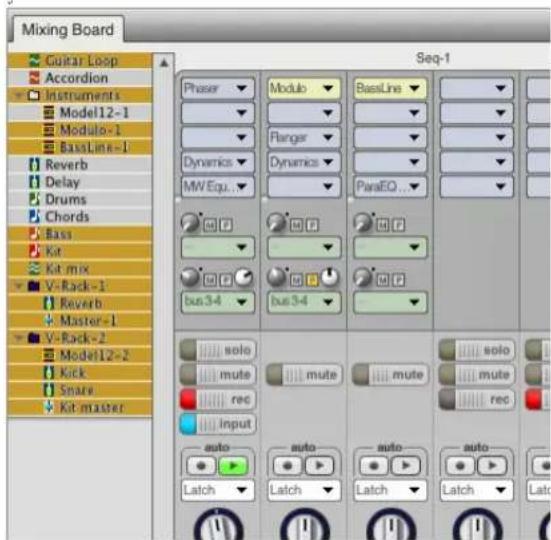
Figure 68-7: V-Rack tracks in the Mixing Board track selector

Figure 68-6: V-Rack tracks alongside sequence tracks in the Mixing Board
Master fader priority
Digital Performer now allows you to assign two or more master faders to the same output pair. But only one can be active at a time. Therefore, master fader priority is determined by their top-to-bottom order in Chunks window list and, within a V-Rack, their left-to-right order in the Mixing Board.
Master Fader tracks in sequences that are higher in the chunk list take priority over Master Fader tracks farther down the list.
Similarly, within a given sequence or V-Rack, Master Fader tracks that are higher in the track list (or further to the left in a V-Rack Mixing Board) take priority over ones farther down (or to the right).
Here's an example: suppose that you have a multiple-sequence project where most sequences share a single “global” mastering V-Rack. However, one sequence’s sonic characteristics are different enough that it requires completely different master stage processing, while still sending its final output to the same output pair as all the other sequences.
In this situation, you could add a master fader directly in the sequence, assign it to the same outputs as the mastering V-Rack, but then place it above the V-Rack in the Chunks window list. When you then make it the play-enabled sequence, its master fader becomes the active (priority) master fader for the output pair. When you play-enable any of the other sequences, the V-Rack master fader becomes active.
In essence, this setup provides a “default” mastering channel, while also allowing “override” mastering channels as needed for individual sequences.
CHAPTER 69 Songs
OVERVIEW
In Digital Performer, a song is a collection of Chunks. The Chunks that make up a song are displayed in that song's window, plotted on a grid beneath a horizontal, non-linear time ruler. The Song window is the work space in which you arrange the Chunks in time and in relation to other Chunks.
By dragging and using standard Edit commands on the Chunks, you can arrange them to graphically represent the order and combinations in which you want them to play back. What you see is what you will hear: adjacent Chunks will play one after the other, and stacked (vertically aligned) Chunks will play simultaneously. Arranging in the Song window can done in real time while the song is playing back.
Quick reference....809
Columns....811
Creating a song....811
Recording MIDI into a song....813
Edit menu commands and the song window .....815
Song window hints....815
QUICK REFERENCE
Chunk Grid: Serves as a workspace in which you arrange Chunks. The grid will not scroll when you drag a Chunk to one of the borders; this allows you to delete a Chunk by dragging it out of the window, or to drag a Chunk to another Song window.
Song Chunks and Sequence Chunks:
Represent songs and sequences that have been dragged into the Song window. Click a Chunk once to select it, twice to open its Song or Tracks window. Change a Chunk's name by Option/Alt-clicking it in the Chunks window. If a Chunk's name is longer than its Chunk icon, the first several letters will be followed by an ellipsis.
A Chunk's size in the Song window is relative to that of the other Chunks in the window, rather than absolute. Chunks shorten and lengthen so that within a region, the longest Chunk always appears longest in the Song window. A Chunk's length can be changed in the Chunks window by setting the Chunk's End time to manual mode and typing in the new value.

Figure 69-1: The Song window lets you arrange sequences and songs graphically in a compact, non-linear display.
The standard Edit commands (Cut, Copy, Paste, Erase, and Undo) and dragging operations can be used on Chunks in the Song window.
Marker Strip: Displays the Markers associated with the open song. Every marker in a song automatically produces a column at the same time location in the Song window.
Time Ruler: Indicates the position of each Chunk in any combination of measure|beat|tick, real, and SMPTE time formats. The Ruler is non-linear, meaning the ruler markings denote Chunk Start and End times rather than regular time units. Choose which time formats are displayed using the Song window mini-menu selections Measures, Real time, and Frames.
Song name: Displays the name of the song to which the window belongs. The song name can be changed by Option/Alt-clicking it in the Chunks window.
Record-enabled Chunk: Displays a record-enable button in its handle, indicating that if the Song is play-enabled and the Record button is pressed, it will begin to record data at its start time. Only sequence Chunks can be record-enabled.
Column: Serves as a placement guide for Chunks. Columns appear automatically at the end of each Chunk, and can be inserted manually by choosing Insert from the Song window mini-menu.
Selected Chunk: Appears inverted to indicate that it has been selected. Selected Chunks are subject to Edit commands as well as several Song window mini-menu commands.
The Song Window Mini-menu
The Song window has the following mini-menu items:
Copy Conductor Tracks: Copies the Conductor tracks of the selected Chunks into the song's Conductor track. In time regions where two or more Chunks are selected, the information from the uppermost Chunk is used. Markers are not included in the copy; use the Merge markers command to copy Chunk markers into a song.
Edit Conductor Track: Opens a Graphic or Event List editing window of the song's Conductor track.
Record-enable Conductor: Enables the Conductor track of the song for recording Tap Tempo information.
Insert Column: Produces a dialog box prompting for a measure, real, or SMPTE time at which to insert a new column.
Set Record Sequence: Enables or disables the selected sequence for recording within the song. Only one sequence can be record-enabled at a time. Choosing this item with more than one Chunk selected, or with a Song selected, produces a warning message.
Merge Markers: Merges the markers of all selected Chunks into the song's marker list.
Delete Markers: Deletes from the song's marker list any markers that are identical to markers in the selected Chunks.
Merge Chunks to Sequence: Produces the Merge Chunks dialog box, which contains the following options:
■ Copy all tracks creates a sequence containing all tracks of the selected Chunks, and places this new sequence in the Chunks window.
■ Merge tracks with identical names creates a sequence containing all tracks in the selected Chunks, merges any tracks with identical names, and places this new sequence in the Chunks window.
Measures/Real time/Frames: Determines which time formats should be displayed in the Song window Time ruler. Choosing a format checks or unchecks it; the checked formats are displayed.
COLUMNS
When you place a Chunk in the Song window, its Start and End times are marked with columns. Columns serve as Chunk placement guides. A column following a Chunk does not necessarily mean that the Chunk will stop playing back at that point.
For example, Sequence-1 is four measures long and has an End time of 5|1|000. Dragging it into a Song window produces a column at the End time, and playback stops there as well.
Now let's say that Sequence-1 contains ten measures of music, but the End time has been manually set to 5|1|000. Dragging the sequence into a Song window still produces a four measure Chunk and a column at 5|1|000, but the Chunk plays back all the way to measure ten.
Inserting Columns
Before you can place a Chunk at a time location in the Song window, there must be a column at that location. Columns appear automatically at the Song's Start time, at each marker in the Song, and at the end of each Chunk dragged into the Song window. You can also insert columns manually.
To insert a column manually:
1 Choose Insert Column from the Song window mini-menu.
A dialog box appears, prompting you for a location in measure|beat|tick, real, or SMPTE time.
2 Click the radio button next to the time format you wish to use, and enter the time.

3 Click OK to confirm your entry or Cancel to cancel the Insert.
If you click OK, the dialog box disappears and a column appears at the time you specified. If you click Cancel, the dialog box disappears and the Song window is unchanged.
4 Place a Chunk at the new column location.
Digital Performer automatically eliminates columns that do not have an associated Chunk or marker. So, if you don't place a Chunk at the new column you have just inserted, the column will disappear when the grid redraws.
CREATING A SONG
Songs are created by dragging Chunk icons from the Chunks window into a Song window, then arranging the Chunks in any playback order and combination you wish. This can be done before or during playback of the Song. To create a song:
1 Choose New Song from the Chunks window mini-menu.
A new, empty song is added to the Chunks list.
2 If necessary, add other songs and sequences to the Chunks list.
For this example we'll assume you have at least two Chunks in addition to the song just added.
3 Open the Song window by double-clicking the song's name in the Chunks window.
The song's window opens. Alternatively, you can open the Song window by clicking its name, then choosing Open Chunks from the Chunks window mini-menu.
4 Grab a Chunk by clicking the icon to the left of its name in the Chunks window.
Release the Chunk in the Chunk Grid beneath the ruler. The Chunk left-justifies to the column at 1|1|000, and a new column appears to the right of the Chunk. Note that you cannot drag the song into its own Song window.
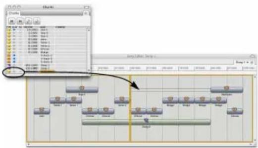
Figure 69-2: Building a song out of sequences by dragging and dropping them from the Chunks list window into a song window.
5 Continue dragging, Option/Alt-dragging, and editing Chunks in the Song window to arrange them as desired.
Chunks that you place end to end will play sequentially; stacked Chunks will play simultaneously.

When placing Chunks into songs, keep the following in mind. Every Chunk has its own Chunk Start time. Every copy of the Chunk uses this time and will reflect any changes made to the original. Specifically, a Chunk's Event List times relate to its own start time, say 1|1|000, even if that Chunk has been dragged into a song to start playing at measure 300.
Similarly, each sequence Chunk has its own Tracks and edit windows, and each song Chunk has its own Song window. Every copy of a Chunk is affected by the edits performed in these windows.
Playing Back a Song
To play a song
1 Click the title bar of the Chunks window to activate it.
2 Click the play-enable button of the song you wish to play.
3 In the Control Panel, click Play.
Adjacent Chunks in the song play sequentially; stacked Chunks play simultaneously.
For another method of playing Chunks one after the other, see “Saving Memory and Auto-Record Times” on page 212.
Scrolling During Playback
The Auto Scroll command (View menu > Scroll) can make the Song window scroll during playback. In addition, the window will
automatically open to the current playback location of the sequence. Please refer to "Auto scroll" on page 226 for more information.
Editing in the Song Window
After you've placed a few Chunks into a song, the Song window offers powerful editing capabilities to help you arrange your music. These operations can be done before or during playback.
Select the Chunk by clicking it, or by dragging a marquee around it.
Open a Chunk's Song or Tracks window by double-clicking its icon.
The standard Edit commands (Cut, Copy, Paste, Erase, and Undo) can all be used on Chunks selected in a Song window, with the following results.
Cut: Removes each selected Chunk from the Chunk Grid and places a copy on the Clipboard.
Copy: Places a copy of each selected Chunk on the Clipboard.
Paste: Makes the cursor change to a mini-likeness of the chunk to be pasted. Click at the desired column location in a Song window to complete the paste operation.
Erase: Removes each selected Chunk from the Chunk Grid; nothing is placed on the Clipboard. You can also delete a Chunk from a Song window by dragging it out of the window.
Undo: Returns the Song window to its state prior to the last Edit or dragging operation. For example, dragging a Chunk to a different column enables the Undo command and updates it to Undo Drag. Choosing Undo Drag returns the dragged Chunk to its original position. Dragging the Chunk to a different column changes its playback start time. You can drag a Chunk from one Song window to another, resulting in a copy in each window.
Option/Alt-dragging, consistent with Digital Performer's graphic track editing, leaves a copy of the Chunk at its original location.
Dragging and Option/Alt-dragging do not cause the Song window to scroll. If you need to place a Chunk at a time location not displayed in the Song window, Cut or Copy the Chunk, use the scroll bars to move to the desired location, insert a column if necessary, and Paste.
Digital Performer lets you record both MIDI and tempo information into a song. MIDI information can be recorded into any sequence Chunk contained in the song, and tempo information can be recorded into the song's Conductor track.
To record MIDI information into a song's component sequence:
1 In the Chunks window, play-enable the Song into which you wish to record.

2 Double-click the song's name to open its Song window.
If the song's window was already open, the window activates.
3 In the Song window, click the sequence Chunk into which you wish to record.
The Chunk highlights; any Chunks that were selected are deselected.
4 Choose Set Record Sequence from the Song window mini-menu.
The highlighted sequence now has a record-enable indicator in its handle. If you change your mind, choose Set Record Sequence again to disable the Chunk.
5 Double-click the record-enabled Chunk.
The Tracks window for the Chunk opens. Each track has a record-enable button.
6 Record-enable one of the sequence's tracks by clicking its record-enable button.
If you wish to record on several tracks, enable (check) Multi Record (Studio menu).
7 Locate the point in the song at which you want to begin recording.
Use the motion controls in the transport controls or set the Counter directly.
8 Click Record.
The song begins to playback. Digital Performer starts recording at the record-enabled Chunk's starting time or the Auto-Record In time and continues indefinitely or until the Auto-Record Out time.
9 When you are finished, click Stop.
To hear the recorded material, rewind as necessary and click Play.
Recording Tempo Information into a Song
Digital Performer also lets you record tempo information into a song. Say you've created a song in which you'd like to have several tempo changes, even rubato passages. Tap Tempo is the most musical way to add these changes to your song — you don't need to guess at the beats per minute, or even the measure numbers where the changes should occur.
Each Chunk has its own Conductor track, containing the tempo, key, and meter information for that Chunk. Instead of recording MIDI events, the Conductor track records tempo information while slaved to Tap Tempo. Tap Tempo lets you control the beat by simply playing a MIDI event like a metronome that Digital Performer follows and can record. If recorded, the information becomes a tempo map that can be edited in the Conductor track and that Digital Performer will follow during subsequent playbacks of the sequence.
You can even record tempo information into the song's Conductor track while recording music into one of the song's component sequences.
To record tempo information into a song's Conductor track:
1 In the Chunks window, play-enable the Song into which you wish to record.
2 Double-click the song's name to open its Song window.
If the song's window was already open, the window activates.
3 Choose Record Enable Conductor Track from the Song window mini-menu.
The song's Conductor track is now record-enabled; this is indicated by a check mark in the mini-menu next to Record Enable Conductor Track.
4 Choose Receive Sync from the Setup menu.
The Receive Sync settings appear.
5 Click the radio button next to Tap Tempo, then choose the port, MIDI channel, MIDI event, and countoff beats you wish to use.
Choose an event/channel combination that you are not using as a Command. Refer to the Commands chapter for information on Commands assignments, and to the Receive Sync chapter for specific information on Tap Tempo.
6 Optional: Click the sequence Chunk into which you wish to record.
If you wish to record MIDI data while recording tempo information, you must record-enable the desired sequence within the song, and tracks within that sequence.
7 Choose Set Record Sequence from the Song Window mini-menu.
The highlighted sequence now has a record-enable indicator in its handle. If you change your mind, choose Set Record Sequence again to disable the Chunk.
8 Double-click the record-enabled Chunk.
The Tracks window for the Chunk opens. Each track has a record-enable button.
9 Record-enable one of the sequence's tracks by clicking its record-enable button.
If you wish to record on several tracks, enable (check) Multi Record (Studio menu).
10 Choose Slave to External Sync from the Setup menu.
11Click Record and begin tapping the specified tap event at the desired tempo.
The Play button remains grey until you have tapped the specified number of countoff beats. Digital Performer starts recording at the record-enabled Chunk's starting time and continues indefinitely or until the Auto-Record Out time, whichever is sooner.
12 When you are finished, click Stop.
To hear the recorded material, rewind as necessary and click Play.
EDIT MENU COMMANDS AND THE SONG WINDOW
The following Edit commands can be used in the Song window: Cut, Copy, Paste, Erase, Select All and Undo. Other Edit commands such as Snip, Splice and Repeat have no effect on Chunks in the Song window.
SONG WINDOW HINTS
The Song window can be used to quickly create special effects. Try some of the suggestions here to get started.
Creating an Echo Effect
To add an echo effect to part of a song, try the following.
1 Find the Chunks that you wish to echo.
Note the starting time of each according to the Song window Time Ruler.
2 Choose Insert Column from the Song window mini-menu.
The Insert Column dialog box appears, prompting you for the measure, real, or frame time at which a column should be inserted.
3 Enter a measure time about 50 ticks after the original Chunk's starting time within the Song.
To create an echo that plays in rhythm with the original Chunk, use divisions of the beat (for example, a quarter note=480 ticks so try 60, 120, or 240). A column will appear in the Song window at the time you specify.
4 While holding down the Option/Alt key on your computer keyboard, drag the Chunk to the new column.
A copy of the Chunk remains at the original location.
5 Play back the song to hear the result.
Experiment with different amounts of delay to achieve the best effect.
Exporting a song to other music software programs
Song Chunks cannot be directly converted to other file formats, but you can use the Merge Chunks to sequence command in the Song window mini-menu to convert the song into a sequence. The resulting sequence can be converted to any alternative file format available in the Save As command dialog box. See “Exporting a project” on page 27.
Managing Markers in a Song
Every Chunk has its own markers. (See “Markers” on page 771 for an introduction to markers.) Markers serve many functions, from simple references to auto-locators. You’ll often find when you place a Chunk into a song that it would be useful to see the Chunk’s markers in the context of the whole song. The Merge Markers command in the Song window mini-menu lets you do just that. Simply select all the component Chunks whose markers you'd like to copy into the song, and choose Merge Markers. All unlocked markers in the selected Chunks now exist in the Song, and are displayed in the Song's marker strip and Markers window.
You can just as easily delete a Chunk's markers from a song. Select the Chunks whose markers should be removed from the song and choose Delete Markers. Digital Performer compares the song's markers to those of the selected Chunks, and removes any that match up. The markers in the Chunk are not affected. Keep in mind that after you merge markers of a Chunk into a song, dragging the Chunk to a different location will not move the markers. Further, selecting the relocated Chunk and choosing Delete Markers will not have any effect, as the markers are no longer associated with the Chunk.
Markers can be of great help when building a song or score because Digital Performer automatically generates a column in the Song window for each marker. You can use the Song's Markers window to create a list of section markers, which will become Chunk placement columns in the Song window. Marker-generated columns are particularly useful for placing Chunks at hit points, which can be created during playback using the Record Hits command found in the Markers window mini-menu for each Chunk.
Chunking and Synchronization
Chunking (arranging Chunks in the Song window) is the ideal method of playing multiple Chunks while slaved to external sync. Firstly, Chunking allows seamless transitions between Chunks within a song. What's more, these Chunks can be edited independently even after they have been dragged into a song.
Secondly, rather than having a different Start time and tempo map for each Chunk within a song, the song itself has one Start time and one Conductor track to govern all component Chunks. In fact, when placing Chunks into a song you could use Set Chunk Start, found in the Chunks window mini-menu, to change each Chunk's start time to correspond with its playback location in the song. The Chunk's SMPTE start times will shift accordingly, matching those in the Song window Time Ruler. If a Chunk contains tempo changes, you can use the Copy Conductor tracks mini-menu command to make every SMPTE time of a component Chunk match those of the song that contains it.
Finally, film scoring applications benefit greatly from the Song window. Using the Record Hits feature in the Markers window, you can create a series of SMPTE hit points associated with a song. Each hit point becomes a marker. Because Digital Performer inserts a column in the Song window for each Marker, you automatically have a Chunk placement guide at each hit point in the song.
Matching chunk start times with their location in a song
When Chunks are placed in a song, the song itself has one Start time and one Conductor track to govern all component Chunks. When placing Chunks into a song, you may want to change each component Chunk's start time to match its playback location in the song. Then, the SMPTE start time of the component Chunk will be the same as its SMPTE location with respect to the song.
To match a component Chunk's SMPTE start time with the song that contains it, look at the column where the Chunk starts in the Song window and make a note of the SMPTE time of the column. Then, set the Chunk's start time to be the same SMPTE time location. For information about how to set the start time, see “Setting the start time” on page 203.
If the component Chunk contains tempo changes, you can use the Copy Conductor tracks mini-menu command to copy all of its tempo changes into the song's Conductor track, making every SMPTE hit point of a component Chunk match its SMPTE time in the song that contains it.
Auto Versus Manual End Time
The Chunks window field End time displays either the automatic, Digital Performer-generated ending time of the Chunk, or a time that you have entered manually. It's important to understand how this time affects your music.
Digital Performer offers two ways of playing Chunks sequentially: by arranging Chunks vertically and horizontally in the Song window, and by Chunk Chaining using the Cue Chunks, Chain Chunks, and Next/Previous Chunk buttons in the Chunks window. The End time shown for each Chunk in the Chunks window affects these two types of chaining differently.
When a Chunk is in a Song window, the Chunks window End time does not affect the playback length of the Chunk. Within a song, a Chunk will play every note it contains, regardless of its Chunks window End time. What it does affect is column placement. Columns appear automatically at the End time of each Chunk dragged into the Song window. This makes it easy to place Chunks end to end.
For example, a Chunk whose last attack is at 4|4|322 will have an automatic End time of 5|1|000. When this Chunk is dragged into a Song window at time 1|1|000, a column will appear at 5|1|000, making it very easy for you to place the next Chunk in a metrically logical location. If you prefer a five measure phrase, just change the End
time to 6|1|000. The end column will appear at 6|1|000, even though the Chunk only plays through four measures.
Again, remember that the Chunk End time does not affect playback in the Song window, only the column placement.
When using the Chunk controls in the Chunks window, you'll find that each Chunk's End time does affect its playback length. For example, clicking Play with the Chain Chunks button enabled causes playback of one Chunk after another, each Chunk playing until the Counter reaches that Chunk's End time. Phrases, even notes that normally would last through the End time will be cut off. You can avoid this by setting a Chunk's End time to be later, thereby building sustain into the Chunk's play length.
In summary: regardless of auto/manual status, in the Song window the End time determines the Chunk's ending column location but not its playback length. During Chunk Chaining, playback actually stops at the End time.
Aux tracks in songs
Aux tracks are always active in songs. For details, see “Using Aux tracks and Songs” on page 159.
Part 7
Mixing
CHAPTER 70 Mixing Board
OVERVIEW
Digital Performer's Mixing Board window provides a powerful integrated mixing environment for MIDI and audio tracks. It also provides access to real-time effects processing and virtual instrument plug-ins.
The Mixing Board will seem familiar because it is modeled after standard hardware consoles. Lurking under the hood, however, are many powerful features, as well as many time-saving shortcuts. This chapter covers them all.
Mixing Board quick reference....822
Mixing Board mini-menu....824
Mixing Board window basics ....825
Track strips....827
Instrument tracks....840
Automated mixing .....841
Mixing in real time....842
Editing your mix graphically....842
Monitoring....842
Audio mixing features....842
Aux tracks....843
Master faders....844
Track groups....844
VCA tracks....844
Remote control....844
Working with effects plug-ins....845
Drag & drop plug-ins ....846
Narrow view in the Mixing Board ....847
Working with multiple mixes....848
MIXING BOARD QUICK REFERENCE

Figure 70-1: The Mixing Board gives you a fully automated mixing environment.
Track Selector: Click or drag over the names of the tracks in this list to show or hide them in the Mixing Board. Option/Alt-click to hide all except the track you click; Command/Ctrl-click to show all except the track you click.
Show/Hide Track Selector: Shows and hides the list of tracks at the left side of the window.
V-Rack Edit: Toggles the Mixing Board between the currently play-enabled sequence and the last viewed V-Rack. Option/Alt-clicking this button toggles the "Show V-Racks" mini-menu option.
Snapshot button: Takes a snapshot of the current mix automation settings of your choice for the tracks and time range you specify. The snapshot operation inserts mix automation events in each included track at the current main counter location. This can be done while Digital Performer is stopped or playing back.
Mix Mode menu: Lets you create and manage multiple mixes for a sequence. A mix consists of all of the volume pan and effects automation data in all tracks. You can duplicate a current mix and then modify it, or start from scratch by creating a new, blank mix. Volume and pan automation data for the current mix is recorded into tracks as usual with the Mixing Board controls, or with the other continuous controller features in Digital Performer. After you've created more than one mix, you can instantly switch between mixes by choosing them from this menu.
Insert Settings menu: Save, recall, and manage chains of inserts.
Track Insert Section: Displays real-time processing inserts for MIDI and audio tracks. Choose the desired effect from the insert. MIDI track inserts consist of MIDI processing effects such as the transposer and Change velocity. Audio inserts consist of plug-in effects, such as EQ, dynamics, reverbs, delays, and any 3rd-party plugins you currently have installed in your system. You can change the number of inserts per track with the Set Number of Inserts mini-menu item.
MIDI effects processors: MIDI effects processors are non-destructive, real-time output processors that affect the track's playback. The choices include Shift, Quantize, Transpose, Change velocity, Echo and many others. These effects only affect playback and can be changed or turned off (bypassed) at any time. They do not modify the original data in the track.
Audio effects processors: These are real-time, non-destructive audio processing inserts that can be applied to audio tracks.
Audio track sends: Allow you to bus the track's signal, either pre- or post-fader, to other tracks.
EQ and Dynamics: Provide visual feedback and quick-access control of each track's EQ and dynamics plug-ins.
Solo/Mute/Rec/Input: These buttons perform standard solo, mute, record and input monitor enable functions. "Glide" horizontally across these buttons with the mouse to quickly toggle several tracks at once.
Automation: Enables playback and recording of automation data and sets the automation mode. For more information, see chapter 71, “Mix Automation” (page 851).
Pan: For MIDI tracks, the pan knob generates standard MIDI pan controller data (controller #10). Typically, this controls the panning of the MIDI track across the main stereo outputs of the MIDI instrument, although this depends entirely on the instrument. For audio tracks, the pan knob pans an audio track across its pair of outputs, as assigned in the Tracks window. For example, if a
track is assigned to outputs 3 and 4, pan hard left sends the track to output 3; pan hard right sends it to 4. Double-click the pan knob to go to pan center. If pan automation data has been recorded, knobs animate during playback (when the Automation play button is enabled).
Faders: Control volume for each MIDI and audio track by generating MIDI and audio volume events, which can be recorded into the track for automation. Double-click the fader to go to unit gain. If automation data has been recorded, faders animate during playback (when the Automation play button is enabled). If the fader cap is missing, it means that the audio track has been disabled. See “Enabled” on page 150.
Level Meters: The level meters display the audio output level for each audio track. For MIDI tracks, the level meters indicate MIDI note-on velocities.
Track I/O: These menus give you direct access to each track's input and output assignments. Instrument tracks and master faders don't have inputs. MIDI tracks only have an input assignment when the project is in Multi Record mode.
Track name and assignment: Double-click the track name to open the editor for the track. Drag it left or right to move the track in Mixing Board.
Tracks: Each strip in the Mixing Board represents a MIDI, audio, instrument, aux or master fader track in the currently play-enabled sequence. Show or hide them as desired using the Show/ Hide Track Selector (described above). Drag the track strip name horizontally to re-order them.
Window Target: Change which sequence or V-Rack you're viewing in the Mixing Board window, or create a new V-Rack.
MIXING BOARD MINI-MENU
Mixer section show/hide: This section of the mini-menu displays checkable menu items that show and hide each section of the console.
Checked items are visible. Unchecked items are hidden. Hold down the Option/Alt key to hide all sections except the one you choose; use the Command/Ctrl key to show all sections except the one you choose. If the Auto Resize command is checked, the console window will automatically resize itself when sections are shown or hidden. You can use these options to customize your mixing board and save screen real-estate.
By default, sends are not shown. If you would like to use sends in your project, be sure to check 'Sends' in the mini menu.
Auto Resize: When checked, this menu item causes the Mixing Board window to resize itself when sections or tracks are shown or hidden.
Use Narrow View: When checked, this menu item reduces the mixer channels horizontally, enabling you to display more channels in the same space.
V-Rack Edit: Toggles the Mixing Board between the currently play-enabled sequence and the last viewed V-Rack. This is the same as pressing the V-Rack button in the lower left corner of the Mixing Board. See chapter 68, "V-Racks" (page 803).
Show V-Racks: Toggles the display of V-Rack tracks alongside your sequence tracks. See chapter 68, "V-Racks" (page 803).
Enable Mouse Wheel for Sliders and Knobs:
When enabled, the mouse scroll wheel can be used to adjust the volume fader, pan knob, and other sliders and knobs; when disabled, the mouse scroll wheel only scrolls the Mixing Board window.
Set Number of Effect Inserts: Lets you determine the number of insert slots per channel. Up to 20 insert slots can be specified.
Automatically Add Inserts: When checked, the Mixing Board adds another row of inserts automatically when you fill the last (bottom-most) insert slot.
Set Number of Sends: Lets you determine the number of sends per channel. Up to 20 sends can be specified.
Load Board Layout: Rearranges the window with the mixing board layout that you choose from the sub-menu. A layout consists of which tracks and sections are currently showing in the window. There are several preset layouts, such as Show Everything, which shows all tracks and sections. You can also load a layout that you have previously created with the Save Board Layout command. A shortcut for this command is to option-click the Window Target tab of the Mixing Board window.
Save Board Layout: Saves the tracks and mixer sections currently being shown in the window as a customized board layout, which you can name, save, and recall at later time using the Load Board Layout command described above.
Delete Board Layout: Discards the customized board layout that you choose.
Lock Layout to Track Order: Causes the left-to-right order of tracks in the Mixing Board to match the top-to-bottom order of tracks in the Tracks window and Sequence Editor. When it is unchecked, tracks in the Mixing Board can be ordered independently.
New Track Group: Lets you create a track group of any kind.
Attach MIDI Controller: Lets you connect a mixing board fader or knob to an external MIDI controller, such as a mod wheel. This includes send level knobs, send pan and send mute buttons.
Clear MIDI Controller: Removes the connection to an external controller from the knob or fader that you select with the cursor.
Set Default Surround Panners: Enables you to set which kind of surround panner plug-in is used by default when a surround channel is created.
Enable Surround Panner Joystick: When checked, this menu item enables control of surround panners via a standard USB joystick.
Configure Surround Panner Joystick: Allows you to map the controls of a USB joystick to mixing functions such as volume, track selection and surround panning.
Min Time and Value Change: Allows you to set the minimum amount of time between volume and pan events that the mixing board controls will generate when you move them. Also lets you choose the minimum value change. Raising these values can prevent unnecessarily high data density. But raising them too high can result in zipper noise, or audible “stepping” during smooth changes.
MIXING BOARD WINDOW BASICS
The Mixing Board is a track-based mixing console for all MIDI and audio tracks. It has one strip for each track in the sequence.
Opening the Mixing Board
To open the Mixing Board, choose the Mixing Board command from the Project menu. If you have tracks selected at the time, the mixing board will appear with only those tracks showing. If you have multiple sequences in the file, it chooses the
sequence to open by the front-most window on the screen, or alternatively, by which sequence is currently play-enabled.
Showing and hiding tracks
To choose which tracks you want to display, click the Track Selector button (in the lower left corner as shown below) to open the Track Selector. Then just click tracks to either show them or hide them. Option/Alt-click to hide all except the track you click; Command/Ctrl-click to show all except the track you click.

Showing and hiding tracks.
Changing the order of the track strips
To move tracks left or right, drag them by their name at the bottom of the strip.
Showing and hiding sections
Use the section names at the top of the Mixing Board window mini-menu to show and hide console sections, such as the Inserts section. Checked items are visible. Unchecked items are hidden. This allows you to optimize the console appearance for your screen size. Hold down the Option/Alt key to hide all sections except the one you choose; use the Command/Ctrl key to show all sections except the one you choose. If the Auto Resize command is checked, the console window will automatically resize itself when sections are shown or hidden.

Figure 70-2: A simplified Mixing Board layout with several sections hidden, including inserts.
Saving custom board layouts
If you have favorite board layouts that you use frequently, you can save them and later recall them by name. To create a custom board layout:
1 Using the window's Track Selector, show the tracks you want to include in the layout; hide tracks you don't.
2 Using the show/hide section mini-menu commands, show the sections you want to include and hide the ones you don't.
3 Choose Save Board Layout from the mini-menu.
4 Type in a name for the layout and click OK.
Switching board layouts
There are several ways to change board layouts:
■ Choose the layout you want from the Load Board Layout mini-menu command
- Option/Alt-click the Mixing Board's Window Target tab and choose the layout you want from the menu

Figure 70-3: Saving and loading customized board layouts.
Renaming board layouts
To rename a board layout, choose the Rename Board Layout sub-menu item from the Load Board Layout mini-menu command.
Manually resizing the Mixing Board window
You may notice that the Mixing Board window automatically resizes itself when you add or remove tracks, show or hide sections, or switch board layouts. This is because the Auto Resize mini-menu command is checked. If you would prefer to resize the window manually using the grow box in the lower right corner, uncheck Auto Resize.
Switching sequences
To quickly switch the sequence you are looking at in the Mixing Board window, click the window's Window Target tab and choose the desired sequence from the menu. The tracks shown in the Mixing Board will also change when you change the play-enabled sequence.
Switching between sequences and V-Racks
To switch to a V-Rack, click the V-Rack Edit button in the lower left corner of the Mixing Board window or choose V-Rack Edit from the mini-menu to toggle the Mixing Board between the currently play-enabled sequence and the last viewed V-Rack.
Alternatively, click the window's Window Target tab and choose the desired V-Rack from the menu. See chapter 68, "V-Racks" (page 803).
TRACK STRIPS
Each MIDI and audio track strip has the sections shown below in Figure 70-4 on page 828.
Inserts
An insert is a real-time effect that is non-destructively applied to the data in the track on playback. MIDI tracks can be processed with MIDI plug-ins (such as the transposer and velocity compressor) and audio tracks can be processed with audio plug-ins. Virtual instrument plug-ins can also be inserted on the top-most insert of instrument tracks (see chapter 17, "Instrument Tracks" (page 155)).
Each insert slot in the track can hold one effect. To choose the desired effect plug-in for the insert, see "Choosing a plug-in for an insert" on page 829.
Up to 20 inserts can be simultaneously applied to an individual track, depending on how many inserts are configured with the Set number of inserts mini-menu option. When you choose the desired effect plug-in for the insert slot, the Effects window opens to display the selected processor's parameters. See chapter 74, "Effects Window" (page 891) for more information.
The signal for a track passes through the inserts from top to bottom. Accordingly, inserts are labelled A, B, C, etc. from top to bottom. Similar to hardware mixing consoles, the order in which effects are applied makes a difference, so keep this in mind when employing multiple inserts. Insert settings apply globally to the entire track and are remembered until you change them.
Configuring the number of insert slots (audio tracks only)
If you find yourself running out of insert slots, you can add insert slots with the Set Number of Effect Inserts command located in the mini menu of the Mixing Board. You can configure up to 20 inserts per channel.
MIDI Track Strip Audio Track Strip


Figure 70-4: A Mixing Board track strip.

If you place an effects plug-in in the last (bottommost) insert, another row of inserts will be added automatically. If you don't want this behavior, uncheck the Automatically Add Inserts mini-menu command.
Configuring inserts as pre- or post-fader
Digital Performer allows you to graphically configure inserts as either pre- or post-fader inserts with the pre/post fader divider line as shown below in Figure 70-5. Inserts above the line are pre fader. Inserts below the line are post fader. A pre-fader insert is applied to the signal running through the channel before it reaches the channel's fader; similarly, a post-fader insert effect is applied to the signal after the channel's fader.
You can grab the handle on either side of the pre/post fader divider to move the location of the divider in the inserts chain.

flowchart
graph TD
A["pre fader effect"] --> B["eVerb"]
C["pre/post fader divider"] --> D["ParaEQ ..."]
Figure 70-5: Configuring pre- and post-fader effects with the pre/post fader divider line.
Be careful when boosting gain
Some plug-ins provide volume controls of their own. By default, Digital Performer's effects inserts are pre-fader, so it is possible to boost level above unity gain with a plug-in's volume control. So be careful when setting levels for plug-ins that have been configured pre-fader.
Choosing a plug-in for an insert
For MIDI tracks, insert slots are menus. Simply choose the desired MIDI plug-in from the menu.
For audio tracks, click the insert slot to open the plug-in chooser (Figure 70-6). This window lets you quickly find the effect you are looking for, and you can then click Select to place it in the insert.
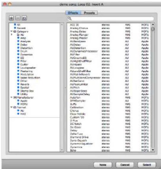
Figure 70-6: Click an audio track insert to open the plug-in chooser.
If an insert already holds a plug-in, right-click or Command/Ctrl-click the existing plug-in to open the plug-in chooser.
Effects versus presets
The plug-in chooser provides two buttons at the top, which let you browse plug-ins by name or by their presets. The window functions in a similar fashion, either way.
Searching
To search for a particular effect or preset, type its name into the search field above the list. All matches appear in the list.
Folders and categories
The left-hand list provides organized folders and categories for your effects plug-ins. Factory-supplied folders include Categories, Manufacturers, and Formats. Use the plus (+), minus (-) and folder buttons above the list to create your own. Or right-click anywhere in the list. User-created categories can be dragged into user-created folders. Folder can also be dragged into other folders to create hierarchical organization.

Figure 70-7: Organizing plug-ins and presets in the chooser.
To organize your plug-ins, drag and drop them from the right-hand list into the categories in the left-hand list. Shift-click and Command/Ctrl-click to select and drag multiple plug-ins at a time.
The same organizational techniques apply to both effects plug-ins and presets.
You can also right-click in the right-hand list to access several shortcuts (Figure 70-8).

Figure 70-8: Right-click the plug-in list to access these shortcuts.
Save As Menu Category
When choosing plug-ins in the Mixing Board inserts, as a shortcut, you can right-click an insert to access a menu of the category you have designated as the Menu Category. To do, right-click the desired category and choose Save As Menu Category (Figure 70-7).
Insert Settings presets
Chains of inserts can be saved and recalled with the Insert Settings menu found at the top of the Inserts section in the Mixing Board and Channel Strip. A variety of factory presets are included, and you can edit, save, and recall your own presets.

Figure 70-9: Insert Settings presets menu in the Mixing Board.
These presets affect only the inserts; other track settings, such as the fader or pan knob, are not affected.
Insert Settings menu commands
Save Insert Settings: saves a new insert settings file.
Delete Insert Settings: deletes the current insert settings file and clears the inserts. You will be warned that the action cannot be undone.
Restore Last Insert Settings: reloads the preset which was most recently loaded.
Open Insert Settings Folder: opens a Finder or Explorer window revealing the insert settings files. There, you can rename, copy, delete, and move your files.
Cut Inserts: Removes all effects on the channel and places the effects chain on the clipboard.
Copy Inserts: Copies all effects on the channel onto the clipboard.
Paste Inserts: Pastes any effects inserts currently on the clipboard onto the track's inserts.
Clear Inserts: removes all effects inserts. On instrument tracks, this command removes only the effects inserts; the instrument insert is unaffected.
Common folder
Presets for each track type (MIDI, Audio, Aux, and so on) are saved in separate folders. However, if you would like a preset to appear in the Insert Settings menu for all types of tracks that use audio effects plug-ins (Audio, Aux, Instrument, and Master Fader), save the preset in the Common folder. Common presets appear at the bottom of the Insert Settings menu on audio tracks.
Insert Settings are clippings
Insert Settings preset files are actually clipping files, so they can be used with all of the usual clippings operations. The insert settings files are located in:
Platform Path
macOS /Library/Application Support/MOTU/Digital Performer/Insert Settings Presets
Windows C:\User\AppData\Local\MOTU\Digital Performer\Insert Settings Presets\
For more information on Clippings, see chapter 55, "Clippings" (page 705).
Bypass toggle
Option/Alt-click the Insert Settings menu to toggle Bypass of all inserts on that track at once.
Insert Settings presets in insert slots
Insert Settings presets can also be loaded from individual insert slots (using the plug-in chooser). In this case, the Insert Settings preset will be spliced in starting at the chosen slot. Other inserts that are already loaded on that track will not be removed; if necessary, existing inserts will be moved to lower slots to allow room for the new inserts.
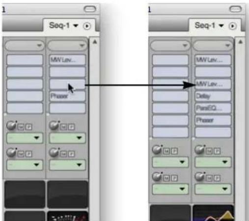
Figure 70-10: Loading an Insert Settings preset in a insert slot will move existing inserts if necessary.
Insert Settings presets when adding instrument tracks
Insert Settings presets are also available when adding an instrument track via Project menu > Add Track > Instrument Track or Project menu > Add Track > Add Instruments.
Sends (audio tracks only)
The Mixing Board provides up to 20 sends per track. (See “Configuring the number of sends” on page 834.) A send can be routed to a physical output in your system or to any virtual bus that you configure in the Bundles window.
Each send has the following controls:

Figure 70-11: Send controls.
When viewing the Mixing Board in Narrow Mode ("Narrow view in the Mixing Board" on page 847), the send mute buttons and pre-fader buttons are converted into a checkable menu command in the send menu.
Mono, stereo or multi-channel sends
Use the Send assignment menu (Figure 70-11) to route the send to any desired bus or output destination. Sends can be assigned to a destination in any channel format, including mono, stereo or multi-channel (surround):
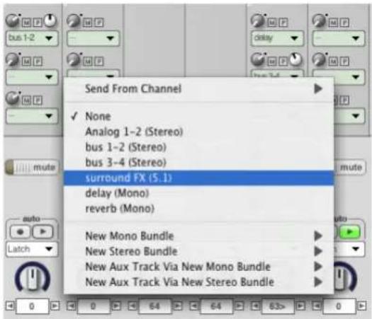
Figure 70-12: In this example, the send is being assigned to a 5.1 surround bus.
Send level
Use the Send level knob (Figure 70-11) to control the amount of signal going to the send destination. The range is from -× to +6.02dB. Double-click the send level knob to set the send level to unity gain (0 dB), as indicated by the blue dot at the 2 o'clock position.
When you turn the send level knob, Digital Performer displays the send amount (in dB) in a pop-up box, as demonstrated below:

Figure 70-13: Send level is displayed as shown here as you adjust the send knob.
Send mute/unmute switch
Click the "M" button to mute or unmute the send. When engaged (on/illuminated), the send is muted.
Pre-fader button
The “P” Pre-fader button (Figure 70-11) determines whether the signal is passed to the send bus before the channel fader (pre) or after the
channel fader (post). When disengaged (off/dark), the send is post-fader. When engaged (on/illuminated), the send is pre-fader. When set to pre-fader, the send level is not affected by the main volume fader of the track. When set to post-fader, it is affected by the main volume fader.
Send panners
If you have assigned a send to a stereo destination, a stereo panner appears, as shown in Figure 70-11, to control send panning. As a shortcut, double-click the panner to return to pan center.
If you have assigned a send to a multi-channel (surround) destination, a surround panner button appears, as shown in Figure 70-11. Click the surround panner button to open a surround panner window, in which you can choose any surround panner you wish for controlling send panning in surround.
Send From Channel
For stereo or multi-channel tracks (or tracks whose signal has been split into stereo or other multi-channel format by insert plug-ins), the Send From Channel menu item (Figure 70-12) lets you choose how the source signal is fed to the send.
For mono send destinations, the Send From Channel sub-menu lets you choose which individual source channel (left, right, etc.) goes to the send. Or you can choose Mono Sum to send all source channels merged down to one channel:

Figure 70-14: The 'Send From Channel' sub-menu for stereo or multi-channel tracks. In the first example, only the left channel of a stereo track is going to the send. In the second example, all channels of a surround track are being summed to a mono send.
For stereo send destinations, choose Stereo from the Send From Channel sub-menu to feed the stereo source signal to the stereo send. Or you can choose an individual component channel (left, right, etc.) to go to the send (in stereo). For example, you could feed only the left channel of the source signal to the left and right channels of the send.

Figure 70-15: The 'Send From Channel' sub-menu for stereo send destinations.
For surround destinations, the Send From Channel menu lets you feed either the multi-channel source signal or an individual component channel to the surround send destination:
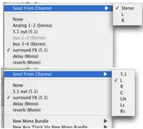
Figure 70-16: The 'Send From Channel' sub-menu for surround send destinations.
Configuring the number of sends
If you find yourself running out of sends, you can add more with the Set Number of Sends command located in the mini menu of the Mixing Board. You can configure up to 20 sends per channel.

Replicating active sends using drag & drop
To replicate an active send (one that already has a send assignment) to any other send slot in the Mixing Board, Option/Alt-drag it to any other empty or occupied send slot.
EQ and Dynamics (audio tracks only)
The EQ and Dynamics sections provide visual feedback and quick-access control of each track's EQ and dynamics plug-ins.

Figure 70-17: The EQ and Dynamics sections in the Mixing Board
Each section has two components: a group of controls for configuring and editing the plug-in, and a graph displaying a visual representation of the plug-in settings.
The controls which edit the plug-in settings work in the same manner as they do in the regular plug-in window, but there are a few additional controls to be aware of which are used for managing the EQ and Dynamics sections themselves.
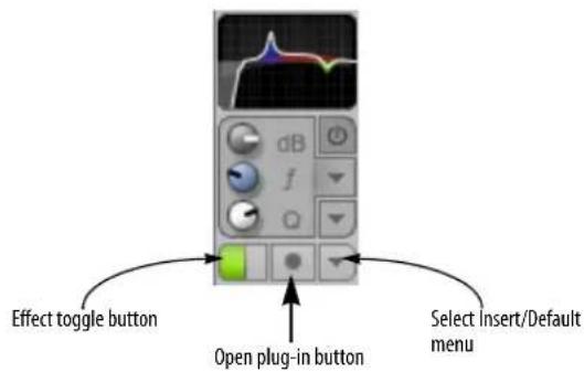
Figure 70-18: EQ and Dynamics controls
Effect toggle button: When the section is empty, this button instantiates the default EQ or Dynamics plug-in (as chosen in the Select Insert/Default menu, below). When a plug-in is already present, clicking this button toggles the plug-in's bypass.
Open plug-in button: Clicking this button opens the Effects window for the associated EQ or Dynamics plug-in.
Select Insert/Default menu: The top portion of this menu chooses the insert assigned to the section; the bottom portion chooses the default kind off EQ or Dynamics plug-in.
Compatible plug-ins
The EQ and Dynamics sections are compatible with all of Digital Performer's included EQ and dynamics plug-ins:
■ MasterWorks EQ
■ ParaEQ (2-, 4-, or 8-band)
■ Dynamics
■ MasterWorks Compressor
■ MasterWorks FET-76
■ MasterWorks Gate
■ MasterWorks Leveler
■ MasterWorks Limiter
Selecting a plug-in
To select a plug-in for the EQ or Dynamics section when the section is empty, you can choose the desired plug-in from the bottom portion of the Select Insert/Default menu. You can also instantiate the default (checked) plug-in by pressing the Effect toggle button or by double-clicking the graph.
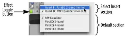
Figure 70-19: Select Insert/Default menu
Alternatively, you can associate the EQ or Dynamics sections with any compatible EQ or Dynamics plug-ins which are already instantiated. Use the top portion of the Select Insert/Default menu to choose an existing instance.
When opening projects from previous versions of Digital Performer, the EQ and Dynamics sections will automatically display the first compatible EQ and Dynamics plug-ins. If you have multiple EQ or Dynamics plug-ins instantiated on a track, use the top portion of the Select Insert/Default menu to change which plug-in's controls appear in the EQ or Dynamics section, as described above.
EQ Controls
The EQ controls display the settings for the EQ band chosen under the Band Selection menu.

Figure 70-20: EQ controls
The controls in the EQ section work similarly when using MasterWorks EQ or ParaEQ. For more information on each plug-in, see “MasterWorks EQ” on page 41 and “ParaEQ” on page 65 in the DP Plug-in Guide.
Dynamics Controls
The controls shown in the Dynamics section vary according to the plug-in you have chosen.
Dynamics
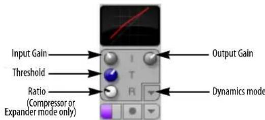
Figure 70-21: Dynamics controls for Dynamics plug-in
For more information, see "Dynamics" on page 27 in the DP Plug-in Guide.
MasterWorks Compressor
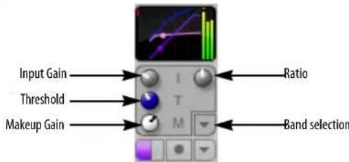
Figure 70-22: Dynamics controls for MasterWorks compressor
For more information, see "MasterWorks Compressor" on page 39 in the DP Plug-in Guide.
MasterWorks Gate

Figure 70-23: Dynamics controls for MasterWorks Gate
For more information, see "MasterWorks Gate" on page 50 in the DP Plug-in Guide.
MasterWorks Leveler

Figure 70-24: Dynamics controls for MasterWorks Leveler
For more information, see "MasterWorks Leveler" on page 52 in the DP Plug-in Guide.
MasterWorks Limiter

Figure 70-25: Dynamics controls for MasterWorks Limiter
For more information, see "MasterWorks Limiter" on page 55 in the DP Plug-in Guide.
Graphs
The EQ and Dynamics graphs provide a visual representation of the plug-in's settings. The graphs are customized for each plug-in so the most relevant settings are displayed. Two example graphs are shown below:

Figure 70-26: EQ and Dynamics graphs
The controls shown in the graphs cannot be edited directly. To edit the plug-in settings, use the EQ or Dynamics controls beneath the graphs, or double-click a graph to open the Effects window.
To toggle the plug-in's bypass state, Option/Alt-click the graph.
Pre-rendering
Showing the EQ and Dynamics sections in the Mixing Board causes any associated plug-ins to be processed in real-time, i.e. not pre-rendered.
Hiding the EQ and Dynamics sections
The EQ and Dynamics sections can be shown or hidden by toggling them in the Mixing Board mini-menu. The EQ Controls, EQ Graph, Dynamics Controls, and Dynamics Graph can all be hidden or shown independently.
Solo / Mute buttons
Solo and Mute buttons perform standard soloing and muting functions for each track. In fact, they correspond directly to the soloing and muting features throughout DP. For example, if you mute a track in the Mixing Board, its play-enable button becomes disabled in the Tracks window.
When soloing and muting, the volume fader background color changes to indicate the playback state of the track as follows:
Fader background color Meaning
Blue Track can play
Yellow Track cannot play because at least one other track is soloed
Gray Track is muted
The colors above apply to Digital Performer's factory default appearance (theme). Other themes use different colors. See “Themes” on page 83.
Record / Input (monitor) buttons
The Record button puts the track into record. The Input button engages input monitoring. These buttons function identically to their counterparts in the Sequence Editor and Track List. See “The record button” on page 241 and “Audio input monitoring” on page 241.
Automation play buttons
When the Automation play button is turned off, all automation data in the track is temporarily disabled, allowing you to override the automation data with the current settings.
Button shortcuts
The table below describes several shortcuts for the Solo, Mute, and automation play buttons:
To do this Do this
| To solo or mute all tracks except the one you click | Command/Ctrl-click the track's solo or mute button |
| To unsolo or unmute all tracks except the one you click | Option/Alt-click the track's solo or mute button |
| To change the solo, mute, or auto setting for several adjacent tracks quickly | Drag across the buttons horizontally with the cursor |
Panning
For MIDI tracks, pan pots generate standard MIDI panning controller data (controller #10). The data range for MIDI tracks is zero to 127, where 64 is pan center, 0 is hard left, and 127 is hard right. The data range for audio tracks is <64 (hard left) to 63> (hard right) with zero as pan center.
Pan pots pan an audio track across its pair of outputs. For example, if a track is assigned to outputs 3 and 4, pan left sends the track to output 3; pan right sends it to 4.
Below is a summary of techniques for pan knobs:
To do this Do this
| Change panning smoothly over time | Drag the pan knob up and down or left and right, or click on the number in the value readout and drag up or down |
Go directly to pan center Double-click the knob
Increment or decrement Click the left or right arrow button the pan setting by one
Stereo panning
The following chart demonstrates the results of stereo panning. In general, center the knob for full separation of the stereo signal.
Stereo pan knob position Left signal Right signal

natural_image
Three identical circular gauges with white and blue stripes, no text or symbols visible
natural_image
Three identical circular gauges with metallic contacts, no text or symbols visibleThe Trim plug-in (see "Trim" on page 89 in the DP Plug-in Guide) can be used to invert the phase of an audio signal or constrain the stereo image of a stereo track.
Volume faders
The volume faders control the output level for each MIDI and audio track by generating MIDI and audio volume events, which can be recorded into the track for automation. If automation data has been recorded, faders will animate during playback (when the Automation play button is enabled).
If the fader cap is missing, it means that the audio track has been disabled. See “Enabled” on page 150.
MIDI volume has a scale from 0-127; audio volume is expressed in decibels (dB) where zero is unity gain. Audio faders provide an additional +6 dB of boost above zero dB. For example, if you move a fader in the Mixing Board as high as it can go, it will be set at 6.02 dB above unity gain. This range is provided throughout the program, wherever audio volume data values are displayed.
The background color of volume faders changes depending on the solo and mute state of the track. See "Solo / Mute buttons" on page 837 for details.
Below is a summary of mousing techniques for changing the values of Mixing Board volume faders:

Figure 70-27: Gliding across the Solo, Mute, and automation play buttons. You can combine gliding with the Command/Ctrl and Option/Alt key modifiers as described in the table above.
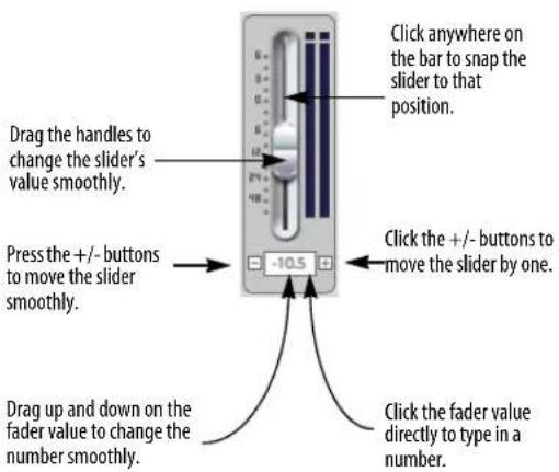
Figure 70-28: The many ways to control a fader.
Using MIDI note velocities to control volume MIDI notes have on-velocities that affect their volume. The range is from zero to 127. You can edit velocities individually in the edit windows, or you can use the Change Velocity command in the Region menu. Keep in mind, however, that velocity only affects the initial volume of the note and offers no way to change the note's volume while it's playing.
Controlling pan, volume and send controls from an external MIDI controller
To control a volume fader, pan knob, send level knobs, send pan, or send mute buttons from an external MIDI controller such as a mod wheel on a keyboard, use the Attach MIDI Controller command in the Mixing Board window mini-menu as described later in this chapter in "Remote control" on page 844.
Using a control surface
There are a number of products designed to function as dedicated physical control surfaces for Digital Performer — see chapter A, “Control Surfaces” (page 1015).
Level meters
For MIDI tracks, the level meters indicate MIDI note-on velocities only (the fader indicates controller #7 MIDI volume).
For audio tracks, the level meters display the audio output level in dB for the track as determined by the volume automation data in the track. The Level Range mini-menu command in the Audio Monitor window controls the dynamic range displayed in the Mixing Board level meters. For details, see “Adjusting the level meter range” on page 268. For even more detailed metering, you can use the Trim plug-in (“Trim” on page 89 in the DP Plug-in Guide), or third-party metering products such as SpectraFoo from Metric Halo.
On stereo or surround audio tracks or tracks that have been made stereo or surround by the application of a stereo or surround (or mono-to-stereo, mono-to-surround, or stereo-to-surround) effects plug-in, the level meter displays the signal with true stereo or surround meters.
Level meters can be globally configured to display the audio level before or after the pan setting for the channel. See “Audio metering is post-pan” on page 95.
Clip indicators
Audio tracks display a clip indicator above their level meter. If the Retain Clip mini-menu command in the Audio Monitor window is checked (see "Retain clip" on page 269 for details), these clip indicators will remain illuminated until you click them. Double-click to clear all clip indicators, or choose Clear all clipping indicators from the Studio menu.
Other ways to monitor input and output levels
In addition to the level meters in the Audio Monitor (Figure 24-6 on page 237), long throw input and output metering is available in the Meter Bridge (“Meter Bridge” on page 885). The Meter
Bridge provides audio track monitoring only, whereas the Mixing Board provides both MIDI and audio track monitoring.
Track name
Track names appear here, with an ellipsis for long names, if necessary. You can drag a name horizontally to reposition its channel strip in the Mixing Board window. Option/Alt-clicking on a name allows you to rename the track from the Mixing Board. Control/Win-click on a name to change the track color.
You can open a track's edit window from the Mixing Board by double-clicking the track name. Use the same modifier keys as you do in the Track List to open the various types of edit windows for each track (as determined by the MIDI Editor preferences – see “Default Edit Windows” on page 91).
Input/Output/Bus Assignment menu
The menu below the track name lets you make the following assignments for the track:
For MIDI tracks, this menu includes a MIDI output device assignment, and a MIDI input device assignment (which is grayed out unless Multi Record is turned on in the Studio menu).
For audio tracks, this menu provides assignments for input and output, bus assignments, and audio track enable/disable. Solo Exempt status is also provided.
In both cases, these are the same assignments that you can make for the track in other windows, such as the Sequence Editor and the Tracks window. They are provided here in the Mixing Board for your convenience.
You can also remove a track entirely using the Delete Track menu item.
For more information about the I/O menus, see chapter 15, "MIDI Tracks" (page 139) and chapter 16, "Audio Tracks" (page 147).

Figure 70-29: Input/output assignments for both MIDI and audio tracks can be made in the Mixing Board with the menu under the track name. This example shows an audio track I/O assignment menu, with Input, output, bussing, and enable/disable assignments.
INSTRUMENT TRACKS
Instrument tracks (Figure 70-30) appear in the Mixing Board, just like audio tracks and MIDI tracks. However, instrument tracks have a special instrument insert, shaded in yellow, at the top of the insert section:
To open an instrument plug-in, choose it from the yellow-shaded menu at the top of the insert section for the instrument track as shown above in Figure 70-30.
In other respects, virtual instrument plug-ins work the same as audio effects plug-ins in the Mixing Board.
For more information about virtual instruments, see chapter 17, "Instrument Tracks" (page 155).

Figure 70-30: An instrument track in the Mixing Board.
AUTOMATED MIXING
The Mixing Board is a powerful environment in which to automate the combined mix of your MIDI and audio tracks. This section explains how to accomplish basic mixing tasks with the Mixing Board.
The importance of event chasing for MIDI tracks
Automated mixing of MIDI tracks in Digital Performer is heavily dependent on event chasing. Event chasing causes Digital Performer to always scan tracks for MIDI controller events to make sure that playback levels are correct, regardless of where you start playback. (For complete information, see “Event Chasing” on page 224.) For consistency during the mixing process, it is best to enable event chasing for MIDI controllers. To do so, choose the Event Chasing command from the Setup menu and make sure that these items are checked.
Setting initial levels with the Mixing Board
Regardless of whether you plan to automate your mixing directly in Digital Performer or externally using an automated mixing console or other hardware automation system, it is always best to set initial mix automation settings in all of your tracks. This ensures consistency in your mix, gives Digital Performer an initial setting to chase to, and gives you a basis for any changes made later in each track. Digital Performer's snapshot feature is a powerful and convenient way to create initial values. Snapshots can include any mix automation parameters, including volume, pan, plug-in parameters, mutes, solos, etc. See “Snapshot automation” on page 864.

Figure 70-31: The Snapshot button.
Setting initial values in MIDI tracks
To set initial values in MIDI tracks, you can either insert volume and pan controllers at the beginning of each track (either individually or all at once via a snapshot), or you can simply set the volume fader and pan knob as desired in the Mixing Board. In the latter case, be sure that MIDI volume and pan are being chased (make sure they are checked in the Event Chasing dialog in the Setup menu).
Defeating initial volume and pan values in MIDI tracks
There may be times when you wish to prevent Digital Performer from sending initial volume and pan controllers for MIDI tracks. For example, you may want to control volume from the front panel
of your synthesizer. If so, you can either defeat volume and pan initialization globally for all MIDI tracks, or disable it specifically for individual tracks.
To defeat volume and pan initialization globally for all MIDI tracks, turn off MIDI volume and pan in the Event Chasing window (Setup menu).
To defeat volume and pan initialization for a few individual tracks (while preserving it for others):
■ Be sure that MIDI volume and pan chasing is turned on globally (in the Event Chasing window)
- Use the Automation Setup window (Setup menu) to defeat MIDI volume and pan for the desired individual MIDI tracks. (For details about this window, see “Automation setup for each track” on page 853.) In this case, volume and pan controllers will not be sent, regardless of whether automation playback is enabled for the track or not.
Viewing initial settings
To view initial settings, open the Sequence Editor select volume or pan from one of the track display menus with the Option/Alt key held down (which switches all tracks to display volume). To make changes graphically, drag the control points up or down as desired.
Making snapshots elsewhere in the mix
You can make snapshots as described above anywhere in your Digital Performer mix.
Changing initial levels (or any snapshot)
You can change your initial settings at any time, or any snapshot for that matter, by queuing to the same tick location in the main counter and repeating the procedure described earlier in "Setting initial levels with the Mixing Board". The snapshot feature will never duplicate controller data on the same tick, replacing existing data with the new snapshot value if data already exists at that location. Just make sure the main counter is exactly at 1|1|000 (or wherever your initial settings are located).
MIXING IN REAL TIME
Mix automation is control data that changes the behavior of the effects and mixing board over time. Automation data can be recorded, edited and played back using the sophisticated set of tools that Digital Performer provides. Automation data can be used to control volume, pan, sends and most effects parameters. For complete information on automation, see chapter 71, “Mix Automation” (page 851).
EDITING YOUR MIX GRAPHICALLY
You can edit your mix graphically in the Sequence Editor and MIDI Editor. See “Inserting and editing automation” on page 860.
MONITORING
An important part of mixing is the process of monitoring live inputs. A live input could be a signal that you are currently recording, such as a microphone, or it could also be a stereo input from a MIDI instrument that you are triggering live from a MIDI track. For complete information about monitoring, see “MIDI input monitoring” on page 238 and “Audio input monitoring” on page 241. Also see “Effects can be applied to Patch Thru” on page 845.
AUDIO MIXING FEATURES
The Mixing Board and Effects windows gives you access to Digital Performer's sophisticated digital audio mixing and routing environment. The following sections discuss several topics that are specific to audio mixing.
Audio mixing features
Digital Performer's virtual mixing environment provides the following features:
■ Mixing
■ Surround mixing
■ Automation
■ Bussing
■ Audio track sends
■ Aux tracks
■ Master faders
■ Real time effects plug-ins
Surround mixing
For complete details, see chapter 72, “Mixing in Surround” (page 871).
Bussing
A bus is an internal signal path. Digital Performer's virtual bussing is modeled after a conventional mixing board. Under the MOTU Audio System, Digital Performer provides up to 1,024 stereo busses. You can set the number of busses in the Studio Configuration dialog as shown in Figure 4-4 on page 33 in the DP4 Getting Started Guide.
A bus routes signal from one place to another. It can also combine several signals as a sub-mix and route them together. To use a bus, you assign a bus bundle as an input or output of an audio track or aux track (explained in the next section). You can also assign a bus bundle as the output of a master fader. Audio track sends can also be assigned to a bus.
There are many useful ways to employ this powerful bussing architecture. For example, you can save large amounts of your system's processing resources by applying effects plug-ins to an aux track and then bussing multiple audio tracks to it, rather than applying the same plug-in multiple times to each individual audio track. By applying the plug-in only once on the aux track, you conserve processing resources.
The impact of mixing and bussing on MOTU Audio System resources
The MOTU Audio System relies on the main CPU in your computer for all of its processing. Mixing and bussing require a certain amount of CPU power; the more you mix, split, route, and merge tracks using input, output and bus assignments in the Tracks window and Mixing Board, the more CPU power you'll use up. You can keep an eye on how much by viewing the Audio Performance window as shown in Figure 4-6 on page 36 in the DP4 Getting Started Guide. Each time you make a connection, split a signal, or merge two or more signals together in Digital Performer's virtual mixing environment, you'll use a tiny bit more CPU power. However, the amount of bandwidth taken up by such a connection is relatively small compared to the amounts required by MOTU Audio System effects plug-ins—even low-overhead ones like the EQ plug-ins. You won't need to be very concerned about CPU power for basic mixing and routing. But you will need to be a lot more conscious of your CPU resources as soon as you start using effects plug-ins.
Multi-processor support
When operating Digital Performer with the MOTU Audio System on a multi-processor or multi-core computer, you can take full advantage of distributed processing. A dual-processor or dual-core computer, for example, effectively doubles the amount of processing available for mixing and plug-in processing (over its single-CPU or single-core counterpart). If you have a multi-processor/core computer, Digital Performer takes full advantage of the multiple processors/cores.
AUX TRACKS
In the Mixing Board, Aux tracks look just like disk tracks, with effects inserts, sends, solo, mute, etc. The only difference is that aux tracks have no input monitoring button and no record-enable button. If the Aux track has stereo inputs, it will
only display stereo effects plug-ins in the effects insert menus. If the track has mono inputs, it will only display mono or mono-to-stereo plug-ins in the insert menus. The same principle holds true for surround tracks. Aux tracks are primarily intended as a routing mechanism. Aux tracks allow you to route audio from any source to any destination. For further information, see chapter 18, “Aux Tracks and Master Fader Tracks” (page 159).
MASTER FADERS
In the Mixing Board, the only way master faders differ from other types of audio tracks is that they do not have a pan knob or surround panner. In their place, master faders have built in fold-down menu. When working in stereo or surround, the fold-down menu allows you to 'fold down' your mix to stereo or mono if you need to generate a mono or stereo mix or to check for mono/stereo compatibility. Note that you can apply plug-ins to the inserts of a master fader to apply the plug-in effect to your entire mix (or all tracks being sub-mixed to that master fader). For additional information about master faders, see chapter 18, "Aux Tracks and Master Fader Tracks" (page 159).
TRACK GROUPS
Digital Performer allows you to create an unlimited number of track groups. Tracks can be linked for mixing, editing, both, or for a customized set of operations that you specify. Tracks can be a member of more than one group. Groups can also be “nested” within each other.
For information about track groups, refer to "Track Groups" on page 188.
VCA TRACKS
Similar to their analog mixing console counterparts, VCA tracks are used to control the relative volume, and other mixing parameters, of a group of other tracks with a single VCA track. You can create as many VCA tracks as you want in your mix, and you can even have VCA tracks control other VCA tracks as sub-groups. See chapter 19, "VCA Tracks" (page 163).
REMOTE CONTROL
You can control any of the faders or pan knobs in the Mixing Board from any external source that can generate MIDI controller data, such as a mod wheel on your controller keyboard or a fader on a control surface that generates MIDI data.
Attaching a MIDI controller to faders and pan knobs
Use the Attach MIDI Controller command to set up external control of faders and pan knobs as follows:
1 Choose Attach MIDI Controller.
The cursor changes to a plus sign.
2 Click the fader or pan knob you wish to control externally.
A red box appears around the control indicating that Digital Performer is waiting for an incoming MIDI controller event.
3 Transmit the data from your MIDI Controller and the box flashes green.
Only MIDI continuous controller data can be used; pitch bend, note-ons, etc. cannot.
4 (Optional) Click another fader or pan knob, or use the arrow keys to move the flashing box around to attach other controls in a similar fashion.
5 When you are done attaching controllers, press return or enter, or double-click the last item you attached.
To cancel, press Command/Ctrl-period (.), the Escape key (Esc), or click elsewhere in the window (such as the title bar).
Clearing MIDI controllers
Use the Clear MIDI Controller command to display all controls that have MIDI controllers attached. They all flash green. Click a control to detach it from the controller. Type Return or Enter to confirm the detachment or Command/Ctrl-period (.) to cancel.
Attaching a MIDI controller to sends or send pan
To attach a MIDI controller to a send knob or send pan knob in the Mixing Board, use the Learn Controller command. See “Attaching a MIDI controller to plug-in parameters” on page 906.
Setting the punch-out delay
When you record a fader or knob via remote control, it punches in and out in much the same fashion as when you grab it with the mouse. To punch in, the fader or knob waits to receive an event from its external controller. When it does, it punches in. Punch out, however, is done automatically by Digital Performer and is determined by the amount of time after the last event was received from the controller. Since controllers send data with different degrees of sensitivity, you may find that punch out occurs too frequently. To avoid stuttering the punch out, you can lengthen the delay before Digital Performer punches out with the Auto Punch-Out Delay command in the Automation Setup window (Setup menu).

Dedicated automated control surfaces
Digital Performer provides an open control surface plug-in format for third-party automated control surface products. Many companies have written Digital Performer plug-ins for their control surfaces, allowing you to use the products for tactile control of Digital Performer's mixing environment, as well as many other features, such as transport control, editing, and much more. For more information, see Appendix A, “Control Surfaces” page (1015).
WORKING WITH EFFECTS PLUG-INS
How effects settings apply to a track
Effects settings apply globally to the entire track. To apply an effect to just a portion of a track, you can use bypass automation to disable, enable and then disable again the effect. Or you can apply the effect ‘constructively’ using one of the following procedures. Make a time range selection in the track and then do one of the following:
■ Bounce to disk (for audio tracks only)
■ Choose Capture real-time MIDI effects in the Region menu (MIDI tracks only)
- Save the plug-in settings as a preset, remove the real-time plug-in from the track (delete the plug-in from the insert) and then apply it 'constructively' from the Audio menu>Apply Plug-in submenu using the same preset you just saved. (Audio tracks only)
Effects can be applied to Patch Thru
Both MIDI and audio effects processors can be applied to any MIDI or audio input that you are Patching Thru. To real-time process a patched thru signal:
1 Assign the desired effects insert to a track in the Mixing Board window insert section.
2 Record-enable the track in the Tracks window.
3 If its a MIDI track, play your MIDI controller.
4 If its an audio track, feed live audio to its input.
Patch thru effects work even when playback is stopped
Plug-in effects can be applied to a live input signal, even when playback is stopped.
Audio monitoring settings
When monitoring live audio through MAS effects, be sure to enable Monitor record-enabled tracks through effects in the Input Monitoring Mode window which is accessed from the Configure Audio System (Setup menu). For details, see "Audio input monitoring" on page 241.

Copying and pasting parameters from one insert to another
You can copy and paste effects parameters from one insert to another. Just choose Copy from the Edit menu while a specific insert's effect is being displayed, switch to a different insert with that same effect, and choose Paste.
Plug-in insert assignments and effects settings are remembered
Effects settings are saved with the file. In addition, the settings for each insert and track are remembered even if you temporarily remove the effect and re-apply later on. Settings are also remembered if you switch audio hardware.
Mono, stereo and surround effects
Audio plug-ins come in mono, stereo and surround variants. When using a stereo mix bus destination, effects plug-ins can be mono-tomono, stereo-to-stereo or mono-to-stereo. When using a surround mix bus, effects offer even more configurations, but we'll cover that in chapter 72, "Mixing in Surround" (page 871). If a mono audio track is assigned to a stereo bundle, it is panned across the bundle's output pair. If you assign mono plug-in, the track remains mono. However, as soon as you choose a mono-to-stereo plug-in, the track's output becomes stereo. In addition, all plug-ins on subsequent inserts will dynamically switch to stereo as well. If you remove the stereo plug-in, the track output will revert to mono.
When DSP resources are exceeded
Digital Performer will warn you if it cannot successfully allocate resources as a result of something that you do, such as add more audio tracks or choose a new type of effect.
Missing plug-ins in effects inserts
If an effect plug-in is missing when you open a Digital Performer project that uses it, an alert window appears, and you are given the option of remembering or forgetting the missing plug-in. If you choose to remember it, the missing effect will be displayed in parentheses in any inserts in the Mixing Board where it was being used. This allows you to preserve missing effects assignments in a project when they are not present. For example, you might copy a project from the main computer in your studio onto your laptop, but perhaps your laptop doesn't have all the same plug-ins installed. You can work on the project, save it, and then open it again in the studio without losing plug-in assignments in the Mixing Board.
Drag & drop plug-ins
After you choose a plug-in for an insert, it fills the slot as shown in the Insert section of the channel strip shown in Figure 70-4 on page 828. You can now treat the plug-in as an object that can be selected, deleted, dragged to a different insert, duplicated, or drag & dropped into a Clipping window.
Here is a summary of drag and drop techniques for plug-ins in the Mixing Board.
To do this Do this
| To change to a different plug-in on the same insert | Click the right-hand side of the insert with the chooser cursor to open the plug-in chooser.  |
| To open the plug-in's window | Double-click the left side of the insert with the hand cursor.  |
To select a plug-in Click the left side of the insert with the hand cursor.  | |
| To remove a plug-in Select it and press the delete key. | |
| To move a plug-in to another insert | Position the hand cursor over the left side of the insert, and then drag it. |
| To duplicate a plug-in on another insert | Hold down the Option/Alt key while dragging, as above. |
| To select several plug-ins | Shift-click the left side of each insert with the hand cursor. |
| To move several plug-ins to other inserts | Select them, grab the left side of one of them with the hand cursor, and drag them to the destination inserts. |
| To duplicate several plug-ins | Hold down the Option/Alt key while dragging them with the hand cursor, as above. |
Plug-ins as clippings
Using the hand-grabbing technique described in the previous section, you can drag and drop plug-ins in and out of Clipping windows—or even folders on the computer desktop. This is a handy way to store your favorite plug-in settings. If you want to keep the settings you’ve made in a plug-in for general use, just drag it into a Clipping window. The same applies for groups of plug-ins. If you drag several plug-ins together into a Clipping window, they will be stored as a single clipping. When you drag them back into the insert
section of the Mixing Board window, they will expand back into the original number of plug-ins (taking up one insert for each plug-in, as usual).
When creating the plug-in clipping, you can also use the Copy to Clipping Window command in the Edit menu, as explained in “Plug-in effects clippings” on page 708.
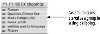
Figure 70-32: Storing plug-in settings in a Clipping window. You can store individual plug-ins or store several plug-ins together as a single clipping.
NARROW VIEW IN THE MIXING BOARD
The Mixing Board also has a “narrow” view that displays more tracks at one time, as shown to the right in Figure 70-33. This feature is a checkable item called Use Narrow View in the Mixing Board mini-menu. Everything works the same way in narrow view as it does in the normal view, with the following exception: the mute buttons and prefader buttons for sends are transformed into a checkable item in each send menu.
There is also a keyboard shortcut that toggles the narrow view and its default key binding is Command-Shift-N.

In narrow mode, the mute buttons and pre-fader buttons for sends are transformed into checkable items in each send menu.
Figure 70-33: To see more tracks at one time in the Mixing Board window, check the 'Use Narrow View' mini-menu item.
WORKING WITH MULTIPLE MIXES
The Mixing Board window has a very powerful feature called the Mix Mode menu, which is located in the lower left-hand corner of the window as shown below. This feature allows you to create an unlimited number of independent mixes in a sequence.

Figure 70-34: The Mix Mode menu.
What is a mix?
A mix consists of all of the volume, pan and other mix settings and automation data in all tracks in the sequence, as well as all of the current effects insert assignments and their settings. The Mix Mode menu allows you to create, save, and recall any number of mixes. Each mix can be completely different than the others. You can also create alternative mixes that are slightly different from each other by starting with the Duplicate Mix command. You can even copy and paste data between mixes by simply switching between them.
How mix mode impacts your sequencing
When Mix Mode is off, mix settings and automation data "belong" to the Track and Take in which they were set, recorded or inserted. If you switch takes, the mix settings and automation data switch along with the take, just like the rest of the data in the take. (For an explanation of takes, see "The Take column" on page 178.)
When Mix Mode is on, however, mix settings and mix automation data "belong" to the current mix. If you switch takes, the mix settings and automation data in the track remain behind as part of the current mix. If, however, you switch to a different mix, the current mix automation data goes along with the mix, temporarily disappearing from all tracks. (You can restore the data, of course, simply by reselecting the Mix from the Mix Mode menu.)
Mixes include initial track settings
Each mix includes the following initial track settings, regardless of whether there is currently any automation data in the track:
■ Track volume
■ Pan
■ Send levels
- Send mute states
■ Track automation mode
■ Track play-enable/disable state
By including these track attributes to each saved mixdown, the Mix Mode menu provides complete independence among separate mixes, even if they don't have any automation data in them. For example, you could simply set initial volume and pan settings for each track, create a mix, duplicate it, adjust the faders and then switch back and forth between the two mixes. You can then freely switch between them, comparing the fader settings, without the need to insert or render any automation data. In general, you will find it very easy to create and use multiple mixdowns because they include initial track settings.
Creating a new or duplicate mix
To create a new, empty mix (with no mix automation data in any of the tracks), choose New Mix from the Mix Mode menu (as shown in Figure 70-34 on page 848). Or you can choose Duplicate Mix to create a new mix based on the current mix (that is, the current volume and pan in all tracks, as well as the current effects insert assignments in the Mixing Board).
Renaming or deleting a mix
To rename or delete a mix, choose it by name from the Mix Mode menu and then choose either Rename Mix or Delete Mix from the same menu.
Recalling a mix
To recall a mix, just choose it by name from the Mix Mode menu Figure 70-34 on page 848.
Copying and pasting data between mixes
You can easily copy and paste data between mixes by switching between them (as described in "Recalling a mix" above). Copy data from the desired tracks in one mix, recall a different mix, and paste into the same or different tracks in the second mix.
CHAPTER 71 Mix Automation
OVERVIEW
Digital Performer's mixing environment offers complete automation of effects plug-in parameters, track muting/unmuting, effects send levels, send mutes/unmutes and more.
Automated mixing for MIDI and audio.....851
Mix automation setup....853
Global automation enable/disable....853
Automation setup for each track....853
Automation settings in other windows....855
Reasons to disable automation....855
Automation modes....856
Recording automation ....860
Inserting and editing automation ....860
Insert and clear Mute Automation ....864
Tempo locked, beat-based automation....864
Snapshot automation ....864
Automation preferences....869
Removing and restoring plug-ins....870
VCA track automation....870
Automation and system resources....870
Control surfaces....870
AUTOMATED MIXING FOR MIDI AND AUDIO
The mix automation features discussed in this chapter apply to both MIDI and audio tracks, except as noted below.
Mix automation in MIDI tracks
Only the following mix automation parameters can be automated in a MIDI track:
■ Volume and pan
■ Track mute/unmute
■ Any form of MIDI continuous data
Mix automation in audio tracks
Audio tracks can automate every mix parameter, including:
■ Volume and pan
■ Track mute/unmute
- Plug-in automation
■ Plug-in bypass/unbypass
■ All other mix parameters
■ Pitch automation
■ Soundbite volume
Mix automation in virtual instrument tracks
Virtual instrument tracks can automate every mix parameter, as above for audio tracks, but there is varying support among virtual instruments for audio track automation. Many virtual instrument products rely on MIDI controller data for automation. For details, see “Instrument track automation” on page 157.
MIDI volume and pan automation
Digital Performer automates MIDI track volume and pan using MIDI controller data (#7 for volume and #10 for pan) to create sudden or smooth volume changes, crossfade effects and panning effects in MIDI tracks. MIDI volume controllers have a range from zero to 127. Unlike note-on velocities, which only affect the initial volume of the note, volume controllers affect volume at any time while a note is playing. Controllers can be inserted, generated, drawn, reshaped, recorded and otherwise handled using the Mixing Board, Sequence Editor and MIDI Editor features described in the rest of this chapter.
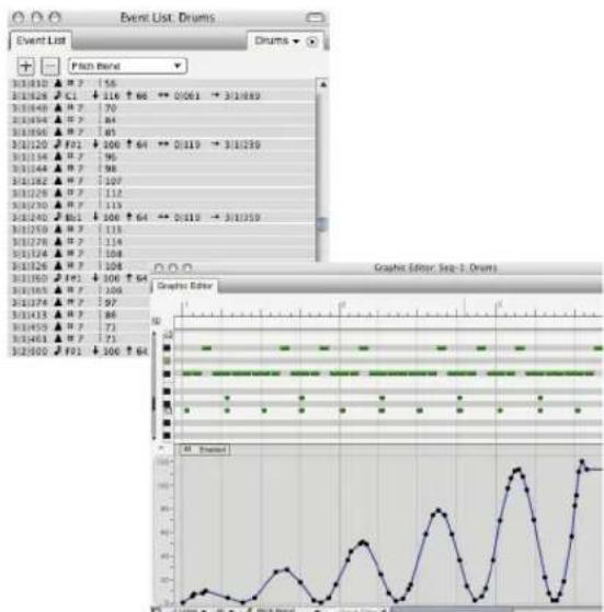
line
| Event | Value | |-------|-------| | 3/1812 | 56 | | 3/1828 | 70 | | 3/1843 | 84 | | 3/1856 | 85 | | 3/1220 | 206 | | 3/1234 | 95 | | 3/1244 | 98 | | 3/1262 | 107 | | 3/1276 | 112 | | 3/1290 | 113 | | 3/1293 | 506 | | 3/1295 | 64 | | 3/1297 | 0.0119 | | 3/1299 | 3/18359 | | 3/1300 | 306 | | 3/1302 | 64 | | 3/1304 | 71 | | 3/1305 | 73 | | 3/1306 | 74 | | 3/1307 | 75 | | 3/1308 | 76 | | 3/1309 | 77 | | 3/1310 | 78 | | 3/1311 | 79 | | 3/1312 | 80 | | 3/1313 | 81 | | 3/1314 | 82 | | 3/1315 | 83 | | 3/1316 | 84 | | 3/1317 | 85 | | 3/1318 | 86 | | 3/1319 | 87 | | 3/1320 | 88 | | 3/1321 | 89 | | 3/1322 | 90 | | 3/1323 | 91 | | 3/1324 | 92 | | 3/1325 | 93 | | 3/1326 | 94 | | 3/1327 | 95 | | 3/1328 | 96 | | 3/1329 | 97 | | 3/1330 | 98 | | 3/1331 | 99 | | 3/1332 | 100 | | 3/1333 | 101 | | 3/1334 | 102 | | 3/1335 | 103 | | 3/1336 | 104 | | 3/1337 | 105 | | 3/1338 | 106 | | 3/1339 | 107 | | 3/1340 | 108 | | 3/1341 | 109 | | 3/1342 | 110 | | 3/1343 | 111 | | 3/1344 | 112 | | 3/1345 | 113 | | 3/1346 | 114 | | 3/1347 | 115 | | 3/1348 | 116 | | 3/1349 | 117 | | 3/1350 | 118 | | 3/1351 | 119 | | 3/1352 | 120 | | 3/1353 | 121 | | 3/1354 | 122 | | 3/1355 | 123 | | 3/1356 | 124 | | 3/1357 | 125 | | 3/1358 | 126 | | 3/1359 | 127 | | 3/1360 | 128 | | 3/1361 | 129 | | 3/1362 | 130 | | 3/1363 | 131 | | 3/1364 | 132 | | 3/1365 | 133 | | 3/1366 | 134 | | 3/1367 | 135 | | 3/1368 | 136 | | 3/1369 | 137 | | 3/1370 | 138 | | 3/1371 | 139 | | 3/1372 | 140 | | 3/1373 | 141 | | 3/1374 | 142 | | 3/1375 | 143 | | 3/1376 | 144 | | 3/1377 | 145 | | 3/1378 | 146 | | 3/1379 | 147 | | 3/1380 | 148 | | 3/1381 | 149 | | 3/1382 | 150 | | F00 | - | | F00 | - | | F00 | - | | F00 | - | | F00 | - | | F00 | - | | F00 | - | | F00 | - | | F00 | - | | F00 | - | | F00 | - | | F00 | - |Figure 71-1: MIDI volume controllers. This smooth volume curve is shown in both the MIDI Editor and the Event List.
Audio mix automation
Digital Performer provides continuous break-point automation for all audio mixing parameters, including volume, pan, and plug-in parameters. Audio mix automation data can be inserted, generated, drawn and reshaped. Unlike MIDI events, which create discrete changes in MIDI volume, audio automation events actually calculate a smooth, sample-accurate ramp from one event to the next. This effect is often referred to as “ramp” automation because graphically, audio volume events produce lines that ramp from one event to the next, as shown below in Figure 71-2. Several volume events can be used together to create volume curves, as demonstrated by the bottom track.
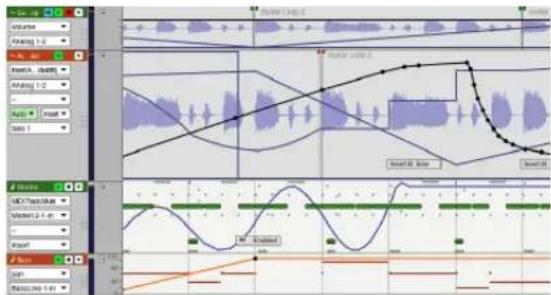
Figure 71-2: Digital Performer's ramp automation features are depicted as sloping lines connecting volume, pan and effects events as shown here.
Pitch automation
For complete details on Digital Performer's real-time pitch automation layer, see chapter 81, "Transposing Audio" (page 935).
The Automation Setup window (Setup menu) provides dynamic control over automation, from a global level to the most detailed level in specific tracks. The Automation Setup window stays open so that you can easily access its features as you work.

Figure 71-3: Automation Setup window (Setup menu).
GLOBAL AUTOMATION ENABLE/DISABLE
As you work with automation, there will be times when you want to temporarily disable automation and later re-enable it. Automation features can be enabled and disabled at any time on several levels:
■ Globally (all automation)
■ Globally by type of automation
■ Per track
■ Per individual effect parameters in a track
The global automation settings let you enable or disable automation altogether, or individually by several types of automation.

Figure 71-4: The global automation enable/disable settings.
To temporarily disable automation altogether, uncheck the Enable Automation check box. Doing so disables the playback or recording of all automation data (including volume and pan), although the data in each track remains unchanged (Figure 71-5), ready for reactivation. To re-enable automation, check the Global Automation check box.


Enabled Disabled
Figure 71-5: When you disable automation data, it appears as a dashed line in the Sequence Editor.
Enabling/disabling globally by data type
Similarly, the Global Automation section (Figure 71-4) has individual enable/disable check boxes for categories of automation data (for both audio and MIDI tracks), including mute, volume, pan, send mutes, send levels, and plug-in effects parameters. For example, you might want to temporarily disable plug-in automation, while maintaining volume and pan automation.
AUTOMATION SETUP FOR EACH TRACK
The Automation Setup window (Figure 71-3) also provides independent automation settings for each track (Figure 71-6). You can enable/disable automation recording, playback, and even individual plug-in parameters. In addition, you can choose one of the different automation recording modes. For convenience, some of these settings are duplicated in each track's channel strip in the Mixing Board, as well as the track settings section in the Sequence Editor (Figure 71-7).

Figure 71-6: Automation setup for an individual track. In this example, the 'Gtr Leads' track has three plug-ins assigned to it: Echo, Reverb and PreAmp-1 ™ .
The track menu
Use this menu to choose the track for which you wish to make automation settings. All of the settings below this menu apply to the track currently chosen in the menu.
Enable automation playback
Check this box to enable automation during playback. Uncheck it to disable automation during playback. This option is a great way to temporarily listen to the material in a track without its automation data, while the rest of the mix is still fully automated.
Enable automation recording
Check this box to allow the recording of automation data during playback. This is an important control because when it is enabled, any changes you make to enabled automation parameters in the track — plug-in settings, panning, volume, etc. — will be recorded. So pay careful attention to this button and only enable it when you're sure you want to record your moves.
Automation record mode
The mode menu lets you choose one of the different ways to record automation data into the track. You can change the mode at any time from the Automation Setup window, the track's channel strip in the Mixing Board or the track settings in the Sequence Editor. For details, see “Automation modes” on page 856.
Enabling automation by data type
Initially, any plug-in parameter can be automated as soon as you begin using the plug-in.
However, you can be very specific regarding the types of data you wish to automate for each track, as shown previously in Figure 71-6. This allows you to automate certain controls, while leaving others 'free' to be tweaked at will. In the example shown in Figure 71-6, The 'Gtr Leads' track currently has three plug-ins assigned to it in the mixing board (as inserts): Echo, Reverb and PreAmp-1. These plug-ins appear in the Add menu, along with Volume, Pan, Send Level, Send Mute, and track Mute. Each plug-in displays a sub-menu for each one of its automatable parameters. Use the Add menu to add automatable parameters to the list, and then use the radio buttons above the list to specify All Except (what's in the list), or Only (what's in the list). To remove items from the list, click them to select them and click Remove. Choosing All enables all plug-in parameters, regardless of what is currently displayed in the list.
'Apply to selected audio/MIDI tracks' button
If you'd like to apply the automation types you've specified in the list to other tracks, select the desired tracks first and then click the Apply to All selected audio/MIDI Tracks button. This operation applies the current track settings to all currently selected audio or MIDI tracks (depending on what type of track is currently being displayed).
'Save as Default for Audio/MIDI tracks' button
If you'd like to apply the automation types you've specified in the list to new tracks automatically when you add them, click the Save as Default for Audio/MIDI Tracks button. There is a separate default state for MIDI and audio tracks. The button changes its wording (audio vs. MIDI) depending on what type of track is currently being displayed.
AUTOMATION SETTINGS IN OTHER WINDOWS
The Mixing Board displays several track-based automation settings directly in the channel strip for each track, just above the pan pot. These settings match the corresponding track settings in the Automation Setup window, the Sequence Editor, the Tracks window and the Effects window, as shown in Figure 71-7. If you change them in one location, they'll change in the others as well. In the Mixing Board, the same Option/Alt-click and Command/Ctrl-click conventions apply to the automation play-enable buttons as for track play-enables. You can also 'glide' over the automation play-enable and record-enable buttons to quickly toggle a series of adjacent tracks.

Figure 71-7: Each track has its own controls for enabling/disabling automation recording and playback. These settings are available in a variety of windows, shown here.
The 'Auto' menu (automation menu)
As shown in Figure 71-7, the automation menu in the Sequence Editor contains the same basic automation mode settings as the Mixing Board and Automation Setup window. In addition, the 'Auto' menu changes color to further indicate the current automation record and playback settings as follows:
'Auto' menu color What it means
Clear Automation playback and recording are both disabled.
Green Automation playback is enabled.
Red Automation playback and recording are both enabled.
REASONS TO DISABLE AUTOMATION
Why would you ever want to disable automation, either globally, per track or even on the basis of individual plug-in parameters? Here are a few common reasons.
One of the main reasons to disable automation, or to enable only a particular plug-in parameter, is that often you are only automating one or two controls in a plug-in. You don't want to worry about accidentally recording changes you make to other controls that you are not automating. By not activating them for automation in the first place, this will never happen, regardless of the track's record mode setting.
Sometimes, you'll want to temporarily experiment with automatable parameters, such as plug-in controls, without accidentally recording your moves as you experiment. For example, you might want to adjust the EQ for a track to get it just right,
but you don't want to record your moves as you're doing so. You can use the Automation Setup window to temporarily disable plug-in automation — or even just the EQ control you are adjusting — while you experiment.
Here's another case where you might want to temporarily disable automation: when you need to do A/B comparisons with and without it. For example, you might want to listen to a passage without the automation you've programmed for it, and then listen to it again with the automation re-enabled.
AUTOMATION MODES
Digital Performer's automation modes provide different ways to record automation. For example, Overwrite mode starts recording immediately when playback begins, overwriting any existing automation in the track. Touch mode, on the other hand, waits for you to grab a knob or fader before it begins recording.
Each track in the Mixing Board can be independently assigned to one of the modes. The automation mode menu for each track is located just above the fader as shown below.

Figure 71-8: The automation modes for each track.
The automation modes are summarized below:
| Automation mode | When it punches in | When it punches out |
| Overwrite As soon as playback begins | Never(When playback stops)* | |
| Touch As soon as you grab the fader or knob | As soon as you release the fader or knob | |
| Latch As soon as you grab the fader or knob | Never(when playback stops)* | |
| Trim Touch ---- Same as Touch ---- | ||
| Trim Latch ---- Same as Latch ---- | ||
| Range Touch -- See “The Range modes” on page 859-- | ||
| Range Latch -- See “The Range modes” on page 859-- | ||
| Range Trim Touch -- See “The Range modes” on page 859-- | ||
| Range Trim Latch -- See “The Range modes” on page 859-- | ||
*In Overwrite or Latch modes, there are actually two ways you can punch out of recording on the fly:
■ Disable automation recording (using any available method for disabling it)
OR
■ Switch to a different automation mode
Playing versus recording
For all automation modes, the track can be either play-enabled for automation or record-enabled for automation. Except for Overwrite mode, the behavior of the controls you modify during playback is the same either way. The only difference is that automation data is or is not written into the track. For example, let's say that a track is play-enabled for automation (but not record-enabled). If you place the track in Touch mode, and you move its volume fader, the fader will return to tracking any existing automated volume levels in the track as soon as you let go of it. On the other hand, if the track is in Latch mode, the fader will remain where you leave it until
playback stops. The next time playback begins, the fader will then return to tracking any existing automated volume levels in the track. Since the track is not record-enabled, no automation data would be written in either case.
Scaling volume data with the Trim modes
Trimming is the process of scaling existing volume or send level automation data in the track, instead of overwriting it entirely. This process is explained in further detail later in “The Trim modes” on page 858.
Overwrite, Latch and Touch modes overwrite existing automation data in the track, whereas Trim Touch and Trim Latch scale existing data. Only track volume and send levels can be trimmed. Other types of automation data are overwritten according to the mode chosen. Here's a summary:
Automation mode Overwrite or scale? Data that's affected
| Overwrite Overwrites All parameters currently beingautomated in the track (exceptthose that you've temporarilydisabled). | ||
| Touch Overwrites Only the parametercurrently being adjusted. | ||
| Latch Overwrites Only the parametercurrently being adjusted. | ||
| Trim Touch Scalesexisting data | Track volume or a send level(whichever item is currentlybeing adjusted). | |
| Trim Latch Scalesexisting data | Track volume or a send level(whichever item is currentlybeing adjusted). | |
Overwrite mode
As shown by the table above, Overwrite mode is special because it overwrites all of the parameters currently being automated in the track. In a sense,
this a way of 'wiping over' them all at once with the settings that you choose before you begin playback.
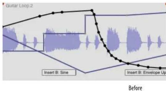

Figure 71-9: Overwrite mode 'wipes over' all currently enabled automation data in the track. The current data is replaced by data that reflects the current knob, fader or other control setting for each parameter. So be sure to set every control you are overwriting to the desired setting before overwriting.
Selective overwriting
You can selectively overwrite automation data while preserving other data by temporarily disabling certain effects parameters in the track beforehand. The disabled parameters will not be overwritten, as shown below in Figure 71-10.
Before

After
Figure 71-10: In this example, everything except volume automation has been temporarily disabled. In Overwrite mode, volume data is overwritten with the current positions of the fader.
Switching to Touch mode after overwriting
Overwrite mode is generally used once in one pass, usually at the start of the mixing stage of your project, or perhaps to wipe over a section that you want to remix entirely. After overwriting, you generally want to touch up the mix from there with the other automation modes (Touch, Latch, etc.) For your convenience, the Automation Setup window (Figure 71-3) has a check box option called Overwrite mode changes to touch after pass. Check this option if you'd like tracks currently in Overwrite mode to automatically switch back to Touch mode after you do an overwrite record pass, so that you don't keep overwriting again and again.
Touch and Latch modes
With the Touch, Latch, Trim Touch and Trim Latch modes, only the parameter you are adjusting is overwritten (or scaled, in the case of the two trim modes). In addition, recording only takes place when you adjust the knob, fader or other control item for the parameter. These modes are the safest because you won't accidentally overwrite existing automation data; they'll only record when you deliberately adjust a control. Just be careful not to record adjustments during playback that are not meant to be inserted. See “Reasons to disable automation” on page 855.
The Trim modes
Trim Touch and Trim Latch modes scale existing volume data or send level data in the track, rather than overwriting it. The two trim modes allow you to increase or decrease volume or send level while maintaining the existing contour in the track. For example, you might painstakingly program a detailed, dynamic volume mix for a track, but later decide that you want to raise the whole thing by 1 dB.
Accordingly, when you switch from a non-trim mode to a trim mode, the scale of the volume fader for the track changes from the normal scale where zero dB is unity gain to a relative scale where zero is the current volume level in the track, whatever it may be at any given moment. The two scales are shown below in Figure 71-11:

Figure 71-11: Latch mode displays the usual volume scale, where 0 dB is unity gain. Trim Latch mode (and Trim Touch) show a relative scale where zero dB is the current automation level in the track at any given location. The send knobs also go into trim mode, as shown.
In Figure 71-12 below, the volume curve is being scaled up by 8 dB using Trim Touch mode.

Figure 71-12: Trim Touch and Trim Latch modes scale existing automation data in the track, maintaining its original contour. The return ramp after punch-out is automatically inserted by Digital Performer to produce a smooth transition between the punch-out level and the remaining automation data.
The Range modes
The Range Touch, Range Latch, Range Trim Touch, and Range Trim Latch modes behave similarly to the regular Touch, Latch, Trim Touch, and Trim Latch modes, but when recording automation using the Range modes, moving controls will change automation data only within a defined time range. The settings for the data on either side of the affected time range will be preserved.
Determining a time range
To specify a time range for the range automation modes, use one of the following methods, which are listed in order of their priority:
1 an event or time range selection in the track
2 a time range selection in another track
3 the Memory Cycle range
Range Latch and Range Touch
With the Range Latch and Range Touch modes, the value of the automation data within the defined time range will become constant according to the setting of the control. Therefore, these modes are useful for adjusting automation data that is already flat, or for leveling a data curve that you wish to flatten.
Range Trim Latch and Range Trim Touch
With the Range Trim latch and Range Trim Touch modes, the current shape of the automation data curve within the time range (if any) is preserved, and the entire curve is moved up or down.
Therefore, these two trim modes are ideal when there is already a shape to the automation data within the time range, and you wish to preserve that shape and simply raise it or lower it altogether.
Using the range automation modes
All four range automation modes are useful when mixing groups of tracks, such as background vocals or horn sections, within a specific time range, where you want to jump in and change the mix just for that range without changing it before or after.
These modes provide the following additional benefits:
■ The range automation modes allow you to use the same control for modifying the data as you did for entering it. For example, if you automated a plug-in filter sweep using the knob in the plug-in window, you can use that same knob to adjust your original sweep, without having to do by some other means (such as editing the automation data in the track).
The range automation modes allow you to make changes to automation data without having to switch edit windows to display the automation data. Instead, you can continue viewing the data you are currently viewing, such as soundbites (or automation data of another type).
Return ramps
A return ramp (Figure 71-12) is an automation ramp automatically inserted by Digital Performer after you punch out from an automation edit. The return ramp makes a smooth transition between the level you were at when you punched out and the level of the any existing automation in the track just after the point where you punched out.
The default length for return ramps is 500 milliseconds (half a second). You can change it to any length you prefer in the Automation Setup window (Figure 71-3 on page 853), and you can change it at any time.
Automation data can be recorded in real time during playback. To do so, enable the automation record button for the track you wish to record (as shown in Figure 71-7), and choose the desired mode (Overwrite, Touch, Latch, etc.) You do not need to put Digital Performer into record mode to record automation. Just start playback and adjust volume, pan, plug-in settings, send levels, and mutes as desired during playback.
The automation data is recorded directly into the track, replacing existing automation data of the same kind, if any.
![Guitar Loop.2 Guitar Loop.2 + - Scandate 231267 ▲ Pan: -41 231311 ▲ Pan: -37 231444 ▲ Pan: -31 231000 □ Insert A: Delay B Bandwidth | 0.519 231001 □ Insert A: Delay B Bandwidth | 0.518 231078 ▲ Pan: -24 231191 ▲ Pan: -16 231290 ▲ Pan: -5 231406 ▲ Pan: 6 231428 ▲ Pan: 20 231442 ▲ Pan: 26 231461 ▲ Pan: 31 231437 ▼ Insert A: Delay B Bandwidth | 1.941 231456 ▼ [Audio Track Mode] Enabled 231480 ▲ Pan: 34 B11000 Guitar Loop.2 B11039 ▲ Pan: 35 B11126 ▲ Pan: 33 B11240 ▲ Pan: 29 B11353 ▲ Pan: 22](/content/2026/05/834832/images/b37c7c0d6dabd316736cfcfdb63e99bcb64e9f016821750591e3c6163e7854f2.jpg)
Figure 71-13: Automation data can be recorded or inserted directly into each audio track.
Controlling MIDI data density
The Min Time and Value Range mini-menu command in the Mixing Board window lets you control the density of the MIDI controller events generated by the Mixing Board faders and knobs in MIDI tracks. Higher minimum values produce lower density, which generally ensures smoother playback performance. But densities that are too low can cause zipper noise or “stair-stepping”. When experimenting with data density, factors such as playback tempo also come into play.
INSERTING AND EDITING AUTOMATION
All of the various types of automation data (plug-in automation, mute automation, send levels, etc.) can be inserted and edited in the Event List, MIDI Editor and Sequence Editor for both MIDI and audio tracks. Use the Insert menus in the Event List or the Pencil and Reshape tools in the Graphic and Sequence Editors to insert and edit automation data. For complete details, see:
■ "Inserting data in the Event List" on page 445
■ “Editing continuous data in Points or Bars mode” on page 427
■ “Editing continuous data in Lines mode” on page 429
- “Working with breakpoint mix automation” on page 403.
■ “Event chasing and audio track editing” on page 226
Please note: some 3rd-party AU and VST plug-ins don't allow numeric editing of automation breakpoints points. In this case, you can drag control points graphically to change their values and inspect the new value in the info bar (or event list).

Figure 71-14: In these examples, automation data is being inserted in the Event List and Sequence Editor.
Generating automation curves
You can generate volume curves using the Insert Continuous Data command in the Region menu. Be sure to select the region over which you'd like to generate the events first. This method gives you precise numerical control over the curve.

Figure 71-15: You can create numerically precise automation changes with the Insert Continuous Data command.
Viewing automation in the Sequence Editor
To view automation data in the Sequence Editor, choose the desired type of automation from the Active Layer menu as shown below in Figure 71-16. When you do, every type of automation data that currently exists in the track will be displayed together, superimposed over the audio waveform. The specific type of data that you chose from the menu will be activated (its ramps and control points will appear in bold). When activated, a parameter's control points can be edited, and new points can be added by clicking anywhere on its line. In addition, some parameters display guides (faint horizontal lines) that indicate values of interest. For example, when you activate Volume, you'll see a guide at unity gain (0 dB) and the top of the scale (6.02 dB). When you activate pan, you'll see guides at pan center and pan hard left/right. For complete details, see "Working with automation control points" on page 863.
![~ Accordion Insert A... d'width Analog 1-2 Auto Insert take 1 Guitar Loop.2 Insert B: Sine Soundbites Volume Pan Loops Pitch Bit Volume Audio Track Mute ✓ Insert A: Delay [L Bandwidth] Insert A: Delay [Bypass] Insert B: Multimode Filter [Envelope Direction] Insert B: Multimode Filter [LFO Waveform]](/content/2026/05/834832/images/fb38a2e308787e6a9beb58c5cbd1228ea7c6ed41826f00e6d4598e9668768c24.jpg)
Figure 71-16: Choose any form of automation data from the Active Layer menu to display all automation data that currently exists in the track, superimposed over the waveform. To 'activate' (make bold) a particular data parameter, choose it from the Active Layer menu or click one of its control points.
The three types of plug-in automation data
Plug-ins have a wide variety of controls that fall into three general types of data:
Automation type What it does Examples
| Ramp Produces a smooth change between control points. | VolumePanSend levelMix gain |
| Stair-step Produces sudden changes among several possible states. | I.FO phaseMute/unmuteBypass/unbypass |
| Single event Changes the setting of a parameter that has only a few settings or non-numeric settings | LFO waveform type (sine, sawtooth, etc.)Note values for beat-based effects. |
All three types of automation are displayed together in the Sequence Editor as shown below in Figure 71-17.
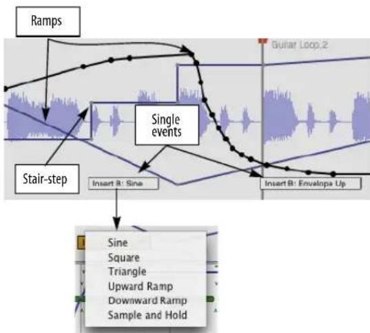
flowchart
graph TD
A["Ramps"] --> B["Stair-step"]
B --> C["Single events"]
C --> D["Insert B: Sine"]
C --> E["Insert B: Envelopa Up"]
F["Sine"] --> G["Square"]
G --> H["Triangle"]
H --> I["Upward Ramp"]
I --> J["Downward Ramp"]
J --> K["Sample and Hold"]
Figure 71-17: The three kinds of automation data: ramps, stair-steps, and single events. Click on a single event to access a menu of settings.
Sample-accurate ramps
Digital Performer's ramp automation produces a smooth change from one control point to the next. Ramps are calculated with sample-accurate, 32-bit floating point processing. Sample-accurate processing ensures that the ramp will be perfectly smooth, with no zipper noise or other unwanted artifacts.
Stair steps
Stair-step automation produces a sudden change at each control point. Stair-step automation is used for plug-in parameters that by nature don't call for smooth changes but instead provide discrete changes among several various states. A good example is the LFO phase controls in Sonic Modulator, which provide eight phase settings in 45-degree increments. Stair steps are also used for parameters that would be too “expensive” from a DSP bandwidth standpoint for calculating ramps. A good example of this is LFO rate.
Discrete events
Discrete events are used for any parameter that consists of two or more non-numeric settings (or just a few numeric ones). A good example is the waveform for an LFO: it could be a sine wave, square wave, sawtooth, triangle, etc. Depending
on the number of possible settings for the event, Digital Performer displays the event either as a single automation event box, as shown in Figure 71-17, or as a stair-step event, with the possible values for the event shown in the ruler.
In the case of the single event box, here is a summary of what you can do with single automation events like these:
To do this: Do this:
| Insert an event Choose it from the insert menu as shown in Figure 71-14 on page 861 and click at the desired location. |
| To delete an event Click it to select it and press delete. |
| To change its setting Press on its menu triangle and choose the desired setting from the menu as shown in Figure 71-17. |
To move an event Drag it.
One important thing to realize about discrete parameter boxes is that they don't display their current value continuously throughout the track the way that ramps and stair steps do. To determine the current setting for a discrete parameter, you need to scroll backwards in the track to find the last discrete event of the type you're concerned with, and then look at its setting there.
Units of measurement
In Digital Performer's included plug-ins, the numeric value for each plug-in effect parameter (displayed in the Event List, Cursor Information window and Event Information window) is displayed with the appropriate format (percent, milliseconds, etc.) for the parameter. This is also true for most third-party plug-ins. Some third-party plug-ins, however, may have their own schemes for displaying parameter values. Check their documentation for details.
Working with automation control points
Here's a summary of techniques for inserting and editing automation control points in the Sequence Editor, including a new techniques for selecting and dragging multiple control points at one time:
To do this: Do this:
| To activate a data type* (make it bold)Note: activating is necessary for all of the following techniques. | Click one of its control points or choose it from the Active Layer menu (Figure 71-16). |
| To insert a control point | Activate the desired data type and then click anywhere. |
| To insert a ramp Activate the desired data type. Then click anywhere on the line as many times as needed to create two or more control points, positioning the control points as needed to make the ramp. | |
| To insert a curve Activate the desired data type. Select Pencil tool and the desired waveform shape from the Tool palette and insert. For more information see “Inserting continuous data in Points or Bars mode” on page 427. | |
| To remove a control point | Click it to select it and press delete. |
| To remove a curve (multiple control points) | Select the control points (as described below) and press the delete key. |
| To select a curve (multiple control points) | Activate it and then drag horizontally over its control points. |
| To move a curve (multiple control points) | Select them as described above and drag one of the selected control points. |
*To activate any type of data other than volume and pan, you must first insert some data (via the Insert menu or by recording) in order for the data to appear in the Active Layer menu (and be available for activation).
INSERT AND CLEAR MUTE AUTOMATION
The Insert Mute Automation and Clear Mute Automation commands in the Region menu allow you to quickly apply and clear mute automation on a region by region basis in any editor window or the Tracks window. Just make a selection, such as an individual soundbite or any time range selection over any combination of MIDI and/or audio tracks, and then choose of these two commands from the Region menu to mute or unmute the selection.
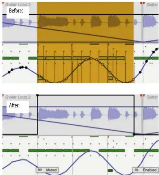
Figure 71-18: Muting a region with the Insert Mute Automation command. Note that two mute automation events are inserted at the beginning of the region to produce the proper stair-step effect.
TEMPO LOCKED, BEAT-BASED AUTOMATION
Some plug-ins allow you to lock certain parameters, such as an LFO, to the tempo of your sequence. This allows the effect to stay in sync with the beat of your music.
For details on tempo-locking effects included with Digital Performer, see “Tempo lock” on page 8 in the DP Plug-in Guide. For details on tempo-locking third-party effects, refer to their documentation.
SNAPSHOT AUTOMATION
An automation snapshot is the process of inserting automation data for multiple mix parameters in one step at a particular location — or over a specified time range. For example, you might want to set initial values at the very beginning the project (e.g. bar 1) for all mix parameters you'll be automating. Or, you might like to reset all values for an entire section of a mix, regardless of the automation data currently there. Digital Performer lets you take a snapshot at a particular point in time or apply it to any time range of your choice. You also have complete control over which parameters to include in a snapshot. Snapshot automation can be applied from the Mixing Board, Sequence Editor, Effects window or other windows. Different default settings can be stored for taking snapshots from these different windows.
Taking a snapshot
To take a snapshot:
1 Prepare for the snapshot as discussed in the next few sections.
2 Choose Take Automation Snapshot from the Region menu, or press the Snapshot button in the Sequence Editor, Mixing Board, or Effects window.

Doing so opens the Automation Snapshot dialog shown below in Figure 71-19:

Figure 71-19: Taking an automation snapshot.
3 Choose the desired settings and click OK.
Preparing for a snapshot
Before you take a snapshot, there are several preparations to make that determine the following characteristics of the snapshot:
■ The time range to be affected
■ The tracks to be included
■ The automation data types to be included
Specifying a location or a time range
Even though automation data consists of discrete events (control points in audio tracks and MIDI controller events in MIDI tracks), it is important to realize that they actually affect your mix over a range of time. For example, if you click on a volume automation line in an audio track to insert a volume control point, ramps are created between the new point and the two points before it and after it. So you've actually affected the entire time range between all three points.
Similarly, when working with automation snapshots, you need to think about the time range that the snapshot will affect and specify it before inserting the snapshot. Digital Performer lets you specify a snapshot's time range in two ways:
■ by positioning the playback wiper (the current counter location)
■ by making a time range selection
The options in the Time Range menu (shown below in Figure 71-20) determine which method to use. Digital Performer then applies the snapshot by placing automation control points (or MIDI controller events) at the start and end of the time range (to maintain the existing automation levels beyond the time range).
When applying a snapshot to all time or a selected range, any existing automation data within the time range is removed.

Figure 71-20: Specifying a time range for the snapshot.
All Time
Use All Time if you wish to apply the snapshot to your entire mix, start to finish. The current counter location or current selection does not matter for this option.
Selected Range
If you would like to apply the snapshot to a particular range of time, make a time range selection in any Digital Performer window before
you take the snapshot and then choose the Selected Range option in the Automation Snapshot dialog (Figure 71-20).
From Counter to Chunk End/Start
This option applies the snapshot from the current counter location all the way to the end or start of the sequence. To use this option, place the playback wiper at the desired location, or type it into the main counter, before taking the snapshot.
From Counter to Next/Previous Change (Flat or Ramp)
This option applies the snapshot to the range of time from the current counter location to the next or previous automation control point (or MIDI controller). It does so independently for each parameter being included in the snapshot. The Flat option produces a constant parameter value throughout the time range being affected by the snapshot; the Ramp option produces a standard automation ramp from the control point inserted at the wiper location to the next or previous control point for each automation parameter. Note that the Ramp option only applies to ramp-style data types, such as volume and pan. See “‘Morphing’ between presets” on page 867 for an interesting way to use this option.
From Previous Change to Next Change
Use this option to apply the snapshot to the entire range of time between two existing snapshots (or any other arrangement of consecutive automation control points). Just place the playback wiper (or counter location) anywhere between them. Use this option to quickly adjust an existing snapshot by placing the wiper anywhere just to the right of it, rather than tediously attempting to place the wiper directly at the location of existing automation data.
If you situate control points at the beginning and end of a section, this option gives you a way to alter the automation in the section in one step.
Specifying tracks
The Tracks menu in the Automation Snapshot dialog gives you several convenient options (Figure 71-21 below) for choosing which tracks to include in the snapshot. If you wish to use the Selected Tracks option, select the desired tracks before taking the snapshot. If you wish to use one of the window display options, be sure to show and hide tracks as desired before taking the snapshot. When using the Edit Window and Mixing Board options, all tracks currently highlighted in the track selector list are included in the snapshot, even if they are not currently visible in the window itself.

Figure 71-21: Specifying the tracks to be included in the snapshot.
Specifying data types
The Data Types menu in the Automation Snapshot dialog gives you several convenient ways (Figure 71-22 below) for determining which types of automation data to write to each track with the snapshot operation.

Figure 71-22: Specifying the data types to be included in the snapshot.
All Enabled Data Types
This option causes the snapshot to write all of the automation data types that are currently enabled in the Automation Setup window (Setup menu). This includes the global enables and the automation enable/disable settings for each individual track. Be sure to enable and disable automation as desired before taking a snapshot using this option.
Current Data Types in Edit Window
This option inserts automation data being displayed in the Sequence Editor window. More specifically, the snapshot only writes automation data that is currently ‘active’ (as demonstrated in Figure 71-16 on page 862) for each included audio track. Notice that only one data type can be active at a time. This option is good for quickly inserting snapshots for the data you are currently viewing in the Sequence Editor. For example, if you are currently displaying volume automation in all audio tracks (volume automation is the active data type for all tracks), use this option to quickly insert a volume-only snapshot.
Data Types Visible in Mixing Board
This option inserts automation data for all automatable controls currently visible in the Mixing Board window. For example, if the Inserts section is currently hidden, no insert level or pan data will be inserted by the snapshot. If you wish to use this option, be sure to use the Mixing Board window mini-menu to show/hide each section as desired before taking the snapshot.
Data types for Current Effect in Effects Window
This option inserts automation data for all automatable parameters of the plug-in currently being shown in the Effects window. This is a great way to automate plug-in presets (by inserting them as snapshots). Also see “‘Morphing’ between presets” on page 867.
Using snapshots to capture automation and apply it elsewhere
You can use Digital Performer's snapshot feature to capture automation settings from one part of your mix and apply them somewhere else. To do so:
1 In the Automation Setup window (Setup menu), enable all automation types you wish to include in the operation.
2 Position the playback wiper (or main counter) at the location in the mix you wish to capture. Doing so causes all automation-enabled knobs, faders and other settings in the Mixing Board to update to their correct values at that point in the mix.
3 Back in the Automation Setup window, globally disable all automation by unchecking the global automation check box. Doing so 'freezes' all knob and fader settings in the Mixing Board, so that they will not move when you change the current playback location.
4 Scroll to the location in the mix at which you'd like to apply the Mixing Board's current automation settings.
5 In the Automation Setup window, check the global automation check box to re-enable automation globally.
At this point, make absolutely sure that the current playback location does not change. Otherwise, the current settings in the Mixing Board will be lost.
6 Take an automation snapshot as usual.
'Morphing' between presets
The Ramp option in the Automation Snapshot Time Range menu (Figure 71-20 on page 865) is a great way to “morph” from one plug-in preset to another as follows:
1 Position the playback wiper (or main counter).
2 Choose a plug-in preset.
3 Take a snapshot of the plug-in parameters.
4 Move the playback wiper forward to the next location at which you'd like to insert a preset.
5 Choose the next preset.
6 Take a snapshot of the plug-in parameters using the From Counter to Previous Change (Ramp) Time Range option.
7 Repeat as desired.
Alternatively, you could start with the final preset in the series you are inserting and work backwards with the From Counter to Next Change (Ramp) Time Range option.
Snapshot settings are remembered
You can take a snapshot from within the following windows (when the window is the front-most, active window):
■ Sequence Editor
■ Mixing Board
■ Effects window
■ Other (Tracks window, other edit windows, etc.)
Digital Performer remembers the snapshot settings you last used in each context. For example, you might only include visible mix parameters when taking a snapshot in the Sequence Editor, but include only plug-in parameters when taking a snapshot from the Effects window. In addition, you might like to always include all mix parameters when taking a snapshot from the Mixing Board. You can specify snapshot settings for each window the first time you take a snapshot from within the window.
Digital Performer then remembers the settings and will use them the next time you take a snapshot from the window.
To reinforce this concept visually, the Automation Snapshot window (Figure 71-19 on page 865) opens directly on top of the window from which it is being invoked.
Digital Performer also stores a generic set of snapshot settings for all other windows. As a result, if you take a snapshot with the Take Automation Snapshot command in the Region menu when the Sequence Editor, Mixing Board or Effects window is not the front-most active window, the settings you see in the Automation Snapshot dialog (Figure 71-19 on page 865) will be remembered independently from the settings for those three windows.
A shortcut for taking snapshots
To take a snapshot from within a window with same settings last used for that window, press Command-Control-single quote ('). Alternatively, you can hold down the Command/Ctrl key while choosing Take Automation Snapshot from the Region menu. Doing so changes the menu command into Take Automation Snapshot Again.
Making the transition to an automated mix
When you first begin working on a Digital Performer project, there is no existing automation data in each track until you record it, insert it by hand or insert it via a snapshot. Beforehand, your mix simply consists of the current fader, knob and insert settings in the Mixing Board. If you record or insert an automation control point for the first time in an audio track, somewhere in the middle of the sequence, Digital Performer automatically extends a line from the control point back to the beginning of the sequence to maintain the initial setting for that parameter in the mixing board. As a result, you get what you would expect: the initial
setting you had made in the mixing board (before automation), followed by the automation data you recorded or inserted.
The above behavior does not apply to MIDI tracks. When you insert MIDI controllers for volume, pan or other mix-related parameters, Digital Performer does not automatically insert an initial value for them at the beginning of the sequence. Doing so is up to you.
Before you begin to automate the mix, you might want to insert initial values for all mix parameters you'll be automating so that you have a convenient reference point to start from. This step is not necessary, but it you might find it helpful to have initial values before you begin automating, especially for MIDI tracks. You can always go back and change the initial values at any time, either by tweaking them individually in the edit window of your choice or by retaking the snapshot at the beginning of the sequence.
AUTOMATION PREFERENCES
The Automation Setup window offers several preferences.

Figure 71-23: Automation preferences
Overwrite mode changes to touch after pass
This automation preference, when checked, causes tracks in Overwrite mode to automatically change over to Touch mode after you record a pass in Overwrite mode. This option helps you to avoid unnecessary or unwanted consecutive overwriting. For details, see “Switching to Touch mode after overwriting” on page 858.
Solo & Play Phrase override mute automation
When this option is checked, soloing a track causes mute automation in the track to be ignored, allowing you to always hear the audio in the track. Similarly, if you press Option/Alt-spacebar to audition some audio, it will play, even if it is currently being muted by mute automation data. If instead, you would like soloing and auditioning to reflect the track's current mute automation, uncheck this option.
Send default volume and pan to MIDI destinations when playback starts
When enabled, MIDI tracks that do not have volume/pan events in the track (and are not controlled by a VCA track with volume automation) will send their current channel strip volume and pan values to their MIDI destinations when starting playback. The preference defaults to being turned off, which should prevent an issue where virtual instrument tracks that had been mixed in the plug-in have their volume and pan parameters reset to the Mixing Board state when starting playback.
Auto return ramp length
At the end of an automation record pass, when you punch out by either releasing the fader or stopping recording altogether, Digital Performer automatically inserts a return ramp at the punch-out point. This ramp produces a smooth transition from the level you were at when you punched out and the existing data in the track at the punch out point. The Auto return ramp length preference determines the length of this ramp. For further details and an example, see “Return ramps” on page 860 and Figure 71-12 on page 859.
Auto punch out delay
This automation preference is useful when you are controlling Digital Performer automation parameters from an external control surface, such as a control surface or a MIDI fader box of some kind. The Auto punch out delay is the amount of time (in milliseconds) after the last event is received from the external knob or fader and the instant when Digital Performer drops out of record (stops recording moves from the external device).
Control surfaces send data with different degrees of sensitivity. With some, you may find that punch out occurs too frequently; with others, you might find that punch-out takes too long. To avoid punch outs that stutter, raise the punch-out delay. To reduce punch-outs that take too long, lower it (but be careful not to lower it so much that it begins to stutter).
Minimum time between recorded points
This automation preference determines how frequently control points will be generated during real-time recording. Lower settings generate more control points that result in finer tracking of your moves. Higher settings produce fewer control points that result in courser tracking of your moves.
Minimum change between recorded points
This automation preference determines how frequently control points will be generated during real-time recording. Lower percentages generate more control points that result in finer tracking of your moves. Higher percentages produce fewer control points that result in courser tracking of your moves.
REMOVING AND RESTORING PLUG-INS
If you remove a plug-in from a track entirely, its automation data remains in the track, and it can still be edited. If you later restore the plug-in (on any insert), the automation data will once again automate the plug-in. Orphaned automation data is displayed in the Track Display menu with italic text, along with the word missing, as demonstrated earlier in Figure 71-16 on page 862.
VCA tracks can be automated, just like audio tracks. Two types of automation data are supported: volume and track mute. Automation is handled in the same fashion as audio tracks. However, there are several unique ways that VCA automation interacts with VCA group tracks. See “VCA tracks and mix automation” on page 165.
AUTOMATION AND SYSTEM RESOURCES
Automation adds to overall CPU processing overhead. If your mix is taxing your computer, you can conserve CPU overhead by enabling automation only for data types and plug-in parameters that you need. For example, don't enable automation for an effect parameter and then insert only one setting for the parameter in the track. Only enable automation for parameters that need to change over time.
CONTROL SURFACES
A number of work surfaces serve as sophisticated, integrated control surfaces for Digital Performer's automated mixing environment. For details, see chapter A, "Control Surfaces" (page 1015).
CHAPTER 72 Mixing in Surround
OVERVIEW
In addition to the mono and stereo formats, Digital Performer also allows you to mix in a number of multichannel or 'surround' formats.
Supported mixing formats include LCRS, Quad, 5.1, 6.1, 7.1 and 10.2.
Surround formats include Dolby Surround (Pro Logic), Dolby Digital, DTS and SDDS. Digital Performer does not provide tools to encode to these formats. You will need to purchase software or hardware that performs the multichannel mix to encoding process.
A surround panner plug-in format provides an open ended method of placing mono or stereo signals in a surround matrix, and surround tracks allow surround sub mixes or 'stems' to be treated as a single track alongside mono and stereo tracks.
Your monitor system ....871
Surround bundles....871
The surround panner dish ....872
Controlling a surround panner with a joystick.....873
Surround formats ....874
Creating a multichannel submix....874
Surround tracks ....875
Fold down....876
Panner plug-ins ....877
ArcPanner....880
N Panner ....880
TriPan ....881
Auralizer ....882
Other surround plug-ins....883
YOUR MONITOR SYSTEM
Proper speaker position and alignment is critical to achieving good results from your surround mix. Consult the manufacturer of your monitor system documentation for proper installation procedures.
SURROUND BUNDLES
Before you can place a mono or stereo source in a surround field, you must have a multichannel destination bundle to send the signal to. Multichannel bundles are created in the Bundles window.

Figure 72-1: Surround bundles.
Figure 72-1 shows all supported surround output assignments, from mono to 10.2.
To create a new surround bundle, click the add button at the bottom of the window. The surround format of the bundle can be changed by using the pull down menu next to the bundle name. Double-click or Option/Alt-click the name to rename the bundle.
Conforming to channel layout standards
The output assignments of the surround bundles can be changed or swapped by grabbing the individual chicklets and moving their positions. One thing this allows you to do is conform the channel layout to a particular standard.
| MV | NAME | NODE | Analog 1 | ||||||
| Analog 2 | Analog 3 | Analog 4 | |||||||
| Analog 5 | Analog 6 | Analog 7 | |||||||
| Analog 8 | Analog 9 | Analog 10 | |||||||
| DTS | 5.1 | L | R | Ls | Rs | C | LFE | ||
| SMPTE/ITU | 5.1 | L | R | C | LFE | Ls | Rs | ||
| Film | 5.1 | L | C | R | Ls | Rs | LFE | ||
See "Input source: Audio bundles" on page 148 for more information on how to create and manage audio bundles.
After an output bundle is created, the destination appears as an available output assignment.
The surround panner dish in the Mixing Board is a standardized representation of the placement of the signal in the surround matrix. Digital
Performer uses an open ended surround panner plug-in format so you can choose what type of surround panner you want to use on a channel per channel basis.
Digital Performer ships with four panner plug-ins:
■ Arc Panner - panning on a radial grid
■ n-Panner - panning using a square X/Y Cartesian grid
■ TriPan - panning using the three-knob panning technique with sophisticated divergence controls
■ Auralizer - a room simulation plug-in that uses a surround matrix to precisely place a sound at specific point.
For more information about panner plug-ins, see "Panner plug-ins" on page 877.
Clicking anywhere in the dish moves the puck instantly to the new position. Double-clicking the dish sends the signal to the front-center position.
The distribution indicator ring surrounds the dish and indicates the direction of the signal's energy distribution.
The appearance of the panning dish depends on the bundle it is assigned to. Each non-LFE (low frequency effects) channel is represented by a pocket on the outside radius of the dish. You can send 100% of the signal to a specific channel by 'pushing' the puck into the surround channel's associated pocket.
Click on a pocket to mute a surround channel. The pocket will turn orange to indicate it is muted.
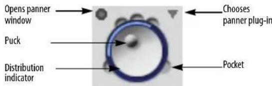
Surround panner movement can be automated along with volume and effects parameters. Editing surround panner automation differs from stereo panners because you have two degrees of freedom to edit: the X and Y position.
![Auto Pan [X] Out 3.1 Auto Insert](/content/2026/05/834832/images/7ca3ffca5a4fd739db787ef109d741a0059a2a2e25304b3209ad6830aa8f958d.jpg)
CONTROLLING A SURROUND PANNER WITH A JOYSTICK
If you would prefer to control surround panning with a physical controller, Digital Performer provides support for any computer USB joystick.
1 Select "Enable Surround Panner Joystick" from the mixing board mini menu.
2 Select "Configure surround Panner Joystick" from the Mixing Board mini-menu.

This brings up the Joystick Setup window.
3 For each Digital Performer mixing function on the left, choose the desired joystick control from the menu to its right. This menu will show all of the USB joystick devices connected to your computer.
Most likely you'll want to map the primary joystick movement to control of the surround panner. Digital Performer provides additional functions to map to the controls such as track selection and volume control. If your joystick has a 'hat' switch, it is a good idea to map track selection to this controller. This allows you to jump from channel to channel without leaving the joystick.
4 After your joystick is configured, hit OK and now you can use the joystick for mixing.

The panner dish of the channel under control of the joystick turns yellow to indicate it is selected. A red ghost puck displays the current position of the joystick before the joystick 'grabs' control of the puck. This allows you to match the current panning position to avoid jumps when recording automation. Use the buttons you defined as track selection to switch channels.
Track selection follows the order of tracks as they are defined in the Track Overview, not the mixing board. If the order of tracks in the mixing board does not match the Track Overview, this can lead to some odd behavior with the track switch function.
SURROUND FORMATS

Stereo Panner

Quad Panner
All channels at 45 degree increments.

LCRS Panner
Left and right channels at 30-degress plus center and rear channels. (Dolby Surround/Pro Logic)

5.1 Panner
Left and right channels at 30-degrees, surrounds at 120 degrees plus center and LFE channel. (Film/Dolby Digital)

6.1 Panner
Like 5.1, but with the addition of a rear center speaker. (Dolby EX)

7.1 Panner
Like 5.1, but with two additional front speakers set at 15 degrees. (SDDS)

10.2 Panner
Front and Rear center channels plus rear surrounds at 120-degrees and six front speakers at 30, 45 and 60 degrees plus two subwoofers.
LCRS (Dolby Surround)
The LCRS mixing format is typically used by Dolby Surround (ProLogic) systems. This format provides four total channels: Left, Right, Center and a rear surround speaker. Most consumer decoders feature two rear speaker outputs which share the single rear channel.
5.1 (Dolby Digital and DTS)
This is a six channel format consisting of five full range speakers and a sixth LFE (low frequency effects) channel. The Dolby Digital and DTS
formats, although sharing the six channel speaker placement, differ in their filtering and encoding procedures.
6.1 (Dolby EX)
This format can be thought of as 5.1 with an additional rear center speaker.
7.1 (SDDS)
The 7.1 format features eight channels of information including a subwoofer. Compared to 5.1, an additional pair of front speakers are used at the 15-degree positions to fill out the front array.
10.2 (TMH)
The rather impressive 10.2 format features front speakers at +/- 30 and 60-degrees. In addition, a pair of speakers are also placed at the +/-45 degree positions, but raised and angled down at a 45-degree angle. In addition, there are rear speakers placed at the center and +/-120 -degree positions, a center speaker and two LFE channels.
CREATING A MULTICHANNEL SUBMIX
You may want to take a portion of your mix and bounce to disk to conserve processing power or simplify your mix.
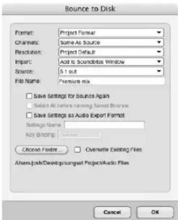
The Bounce to Disk function works the same for surround application as it does for mono or stereo bounces. Bounced submixes can be automatically
imported back into your project and used in "Surround Tracks" For more information, see chapter 84, "Bounce To Disk" (page 953).
SURROUND TRACKS
Surround tracks contain four or more channels of audio information in a single track space.
Surround tracks provide the convenience of editing a multichannel submix as if you were editing a single track. Common uses of surround tracks include playback of bounced surround submixes or recording the output of a multichannel mic array or outboard surround reverb.
While recording into a surround track, the waveforms for all channels are superimposed over each other. After recording finishes, the waveforms for each channel are shown.

Just like stereo tracks, audio files recorded or bounced into a surround track can be interleaved or deinterleaved. When using interleaved, all channels are stored in one file. When using deinterleaved, the files are automatically labeled with the appropriate filename descriptors. The type of surround track is appended as well as individual channel descriptions.

N-channel panners
Surround tracks and channels where a surround signal is sent to the panner (as is the case with an effect like the mono or stereo to n-channel Delay) are displayed as a surround dish with no panner puck. You can mute tracks by clicking on a pocket and fine tune the output and LFE settings using the panner plug-in.

Sends
Each send in a mixing board channel strip is configurable to use any channel of a surround signal, or the entire surround signal. The send's Send from Channel sub-menu determines which channel of the multichannel signal will be the source of the send, or if the entire signal will be sent.

The Master Fader
The master fader functions in a similar manner to a stereo master fader, but the actions of the fader affect a multi channel mix. The effects chain of a master fader is completely n-channels to n-channels so only effects that support n-n processing are available.
Multichannel master faders display a single meter to indicate output activity. The meter represents an average of all channels. For individual meter activity, open the faders mode panner window for the master fader or use a Trim or MasterWorks Limiter on the master fader insert.
Calibration
After you have set up a master fader, it is a good idea to calibrate your mixing environment with the calibration plug-in and save the result as a preset. You should always monitor your mix through the Calibration plug-in, but remember to bypass or disable the plug-in when you write your final mix.
N-Channel effects
Most stereo to stereo effects in Digital Performer also function as n to n-channel effects. Usually n-to-n effects are used on master faders or surround tracks where the entire signal path of the fader is multichannel. Mono or stereo to n-channel can also use n-channel effects under the following circumstances:
■ when preceded by a mono or stereo to n-channel effect such as the delay to n-channel plug-in
■ when inserted below the pre/post fader line on a channel that is assigned to a surround bundle
FOLD DOWN
Fold down enables you to take a multichannel mix and fold it down to mono or stereo. This is useful if you want to want to generate a stereo mix of your surround project, if you simply wish to edit a surround project and do not have access to a full surround monitoring system, or if you would like to preview what your mix will sound like in a theater with only two speakers.
For stereo folddown, left channels are mixed to the left channel of the stereo mix, right channels are mixed to the right channel of the stereo mix and LFE and center channels are sent equally to the left and right channels.
For mono folddown, all channels are summed to both the left and right channels.
With Folddown enabled, the main left/right outputs of the multichannel bundle assumes the role of folddown output.
If you want to monitor a folded down mix on a system with only stereo output such as the computer's built-in audio, do the following:
1 Make sure you have an output bundle for your stereo output.

2 Create a surround bus and a stereo bus with the Bundles window. Make sure the stereo bus shares the same output bus assignment as the left/right channels of the surround bundle.

3 Select all the audio tracks and master fader in the project and use the Track Assignments command (Studio menu) to reassign their outputs to the surround bus you just created.

4 Create an aux channel with the stereo bus as an input and the physical (built-in audio) outputs as the output assignment.

5 Select "Stereo" from the Folddown menu on the master fader and now you can monitor your multichannel mix using a single stereo output.
Directly assigning channels to hardware outputs in a surround configuration
The Bundles window (Studio menu) allows you to create output destinations that share the same physical outputs on your hardware as the output of a surround panner. This is useful if you need to directly assign audio to a specific output without going through a panner - such as assigning dialog to the center channel, or reverb to the rear surrounds.
Direct assignments are also helpful for organizing music and sound effects stems (submixes) when mixing for film.

PANNER PLUG-INS
Digital Performer ships with four panner plug-ins: Auralizer, n-Panner, TriPan and ArcPanner. With the exception of the special Auralizer plug-in, there are some general concepts that apply to all panners.
Panning Stereo Tracks in a Surround Matrix
The panners supplied with Digital Performer provide five modes for panning stereo signals in a surround field.
Balance: Left inputs go to left outputs, right inputs go to right outputs and gains vary with puck position. This mode is similar to how a normal stereo pan knob works, but with an added front to rear axis.

natural_image
Grid with a single red dot at the center (no text or symbols)Figure 72-2: TriPan using balance mode.
Mirror: Two pucks are provided that represent each side of the stereo signal. Moving a puck results in the same movement to be mirrored by the virtual puck the other side of the stereo image. Movement towards the center reduces the stereo image of a track until the center point line after which the stereo image is swapped.

natural_image
Grid with two small colored dots (green and purple) at intersections, no text or symbols presentFigure 72-3: TriPan using Mirror mode
Asymmetric: Two virtual pucks are provided. Two pucks represent the left and right sides of the stereo signal and a center (red) puck is the 'control point'. Stereo image is widest in the center position and gradually decreases as signal is panned left or right of center. Extreme left or right placement results in the left and right input signals summing.

Figure 72-4: Tripan using Asymmetric mode
Parallel: The stereo image is fixed on a 'bar' You move the stereo image throughout the surround matrix with the virtual puck/control point. The stereo image never changes width in this mode.
Mono: The left and right signals are summed to a mono signal before panning.
Filters
All panner plug-ins assigned to bundles with LFE support ('.1' or '.2' bundles) are equipped with in-line filters. These filters allow you to maximize the headroom of your mix bus by filtering out signals that will not be used. If you are using an LFE in your mix, you can use the pre panner high pass filter (HPF) to filter frequencies below 120Hz. Likewise, for the LFE channel, you can filter out signals that occur over 120Hz by using the pre-LFE low pass filter (LPF)

Technically, the LFE channel should only contain frequencies 120Hz and below. Inside of Digital Performer, the LFE channel is full frequency bandwidth and you have the choice of using the
in-line filters built into every panner or filtering the LFE channel on output. If you would like to filter the subwoofer output only, set the pre-pan high pass filter to 20Hz.
Meter Pane
Each panner has an additional section which displays post panner level meters for each channel. You can access the meter pane by clicking the disclosure triangle in the upper right corner of the panner. Here you find meter activity for each channel, LFE Trim and solo and mute for each channel. "Solo" in joystick mode overrides the joystick position and hard assigns the input to the soloed output.

LFE Trim: The LFE trim control is located in the meter pane. This control acts like a send knob for directing signals to the LFE output. If you wish to increase the low end presence of a track, adjust the LFE control until the desired 'thump' is achieved.
Faders Mode
When first opened, mono and stereo to surround panners display joystick mode. However, you may switch to faders mode by clicking the mode select toggle.
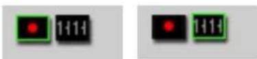
Joystick mode Faders mode
Faders mode provides accurate control in 1/10dB increments over how much signal is sent to each speaker in your surround matrix. For mono-to-surround panners, you have a fader send representing the mono input of the channel per surround output. For stereo-to-surround panners, you have two fader sends per surround output representing the left and right sides of the signal.
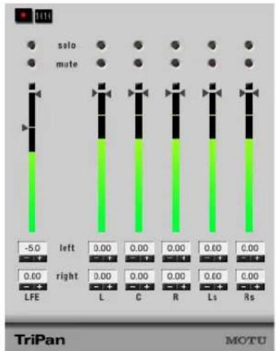
Figure 72-5: TriPan in Faders mode
If the signal is already a multichannel signal before it reaches the panner (as is the case when using a multi channel plug-in like the surround delay plug-in) your panner is automatically set to faders mode and can not be switched to joystick mode.
Surround panners in Digital Performer are designed to accept a mono or stereo input and convert it to a multichannel surround signal. Because the output of the channel is already multi channel when it reaches the panner, you may only use faders mode to tweak the output.
In this mode, each input is hard wired to its corresponding surround output and each fader is a trim.
ARCPANNER

Figure 72-6: ArcPanner
The ArcPanner's panning field is represented on a radial grid. As the positioning puck is moved around the field, a representation of the panning energy is displayed by a green bar on an arc around the panning field.
Angle: Controls the angle, in degrees, from the listening position. If you want to change the angle without changing the width, hold down the Shift key while positioning the mouse and the width will stay fixed. This technique also works in the mixing board.
Width: Width of field, in degrees from listening position.
Focus: Determines the spread of panning across the surround field. The more narrow the focus, the more tightly imaged the panning will be. Higher or more diffuse values will be spread more broadly.
N PANNER

Figure 72-7: n-Panner
n-Panner is the simplest panner. It can be thought of as two independent pan pots, one for the left right ratio and one for the front back ratio. Clicking on any speaker icon places the puck directly to that output.
L/R: Controls the left to right (x-axis) positioning.
F/B: Controls the front to rear (y-axis) positioning.
Focus: Controls how sharply imaged the surround positioning is across the front channels. A lower or diffused setting slightly blurs the
output across all front speakers. A higher setting produces more tightly focused positioning between the two nearest speakers.
TRIPAN

Figure 72-8: TriPan
TriPan is a more elaborate variation on n-Panner. Like n-Panner, TriPan can be thought of as two separate pan pots, one for left-right and one for front-rear. However, TriPan also has a three-knob method of panning which provides precise control for panning signals linearly across a surround field. Three knob panning provides a control for left to right across the front, a control for left to right across the rear and a control for front to rear placement. This method allows you to perform accurate transitions by setting two controls and sweeping a third. For example, if you wish to smoothly pan from the front left speaker to the rear right speaker, set the front control to hard left and set the rear control to hard right. Now simply move the front to rear control and your signal smoothly moves diagonally across the room.
Divergence
By default, TriPan divergence controls are 100% divergent. When fully divergent, a signal panned hard to a single speaker will only come out of that specific speaker. Lowering the divergence allows you to blur the placement of the signal, thus bleeding the signal in to the other speakers for broader coverage.
TriPan offers an independent divergence control for each of the three pan controls. You can tailor the amount of divergence across the front speakers, across the rear speakers or across the front to rear dimension speakers. In addition to displaying the narrowed image divergence provides, the graphic divergence display in TriPan is directly editable by manipulating the handles with the mouse. Positioning a sound outside the blue divergence field results in the signal converging.
In a multichannel mixing environment with a center speaker, the center channel is sometimes reserved for dialog. TriPan gives you control over how much signal gets sent to the center speaker. Reducing the center control avoids sending audio to the center speaker and creates a phantom center location by sending audio to the left and right speakers, thus freeing the center channel.
2-knob vs. 3-knob panning
TriPan provides two methods of positioning audio: 2-knob and 3-knob. When TriPan is in 2-knob mode, the front and rear knobs are linked. When you position a sound with TriPan you will see the front and rear controls are always the same. X/Y panning produces the most degree of freedom inside of TriPan with no diagonal movement constraints. Using the two knob method of panning under certain front to back
panning maneuvers results in some sloppy movement. For example, if you use 2-knob panning to move diagonally from the front left speaker to the rear right speaker, by the time the panner gets to the center, virtually all surround channels are spewing out audio. Three-knob panning allows you to perform the same operation through the center, but only involve the front left and rear right speakers. Of course, TriPan allows you to automate switching of two knob to three knob mode at any time.
AURALIZER
Even though Auralizer is considered a panner plug-in, it might be better thought of as an effects processor that uses the panning architecture of Digital Performer. The other three panners position signals spatially by distributing gain across the speakers in your n-channel matrix. Auralizer is a room simulator that uses a surround speaker matrix to position a sound in three dimensional space. Auralizer is different from simple panners in that the puck distance from the center determines the perceived distance of the signal, not which speakers are active.
Position
The combination of angle and distance determine the relationship of the source signal to the listening position. Positioning in Auralizer works the same way as other panner plug-ins. Simply drag the puck to position the sound.
Angle: Represents the perceived angle from the listening position.
Distance: Represents distance to the sound source as a percentage of the total room size.
Width: Determines the width (in meters) of the original sound source. This supplies another distance cue as a sound source with a large width will seem to originate as a point source when farther away and grow wider as it approaches the

Figure 72-9: Auralizer
listening position. For mono signals, a pseudo stereo image is created. For stereo signals, width controls the spread of the left and right channels.
Room: Allows you to design the characteristics that define the space the audio is traveling in.
Absorption: Determines the reflective properties of the room walls. Higher values are deeper (more absorptive). Lower values are a more live (harder surfaces)
Emphasis: Sometimes it may be necessary to reduce the effects of position cues to be usable in a musical context. The Emphasis parameter allows you to lessen the physical rules of Auralizer if necessary.
Size: Average distance between walls in meters.
Volume: Determines the total volume of room in meters cubed.
Psycho acoustic cues
There are a number of psycho acoustic cues the brain uses to translate audio events into positioning information. You can individually enable or disable these cues in Auralizer:
Doppler: With Doppler enabled, sound is delayed based on its distance from the listener. When the distance changes (via automation or by hand), the delay changes causing a “Doppler shift” in the frequency. Sound traveling toward the listening position will be slightly higher in pitch and sound traveling away from the listening position will be slightly lower in pitch. The amount of frequency shift depends on the rate at which the distance changes. The effect will be more pronounced as the speed increases. This cue is affected by Emphasis.
Head delay: There is a small delay based on the distance between your left and right ears. This cue is important for sounds localized to the left or right of the listening position.
Head shadow: Enables high frequency damping based on position. If a sound is located on the left side of your head, the high frequency response of the right side of your head is slightly dampened.
Distance attenuation: Enables the inverse square law. When a sound source is farther away, the overall volume is lower. This cue is affected by Emphasis.
Reflections: Enables early reflections. The relative volume of the reflections helps cue for source distance.
Reverb: Enables diffuse room reverb. The relative volume of the reverberation helps cue for source distance.
LFE: Determines the amount of signal sent to the LFE channel.
OTHER SURROUND PLUG-INS
For complete information about the surround variants of Digital Performer's included MAS plug-ins, see chapter 1, "Audio Effects Plug-ins" (page 7) in the DP Plug-in Guide.
CHAPTER 73 Meter Bridge
The Meter Bridge window (Figure 73-1) displays level meters for all inputs, outputs, busses, tracks and bundles. With a single click, you can independently show or hide available hardware inputs, available hardware outputs, busses, bundles, virtual instruments and tracks as desired. The Meter Bridge provides long-throw, scalable meters with extremely fast, smooth and accurate ballistics. Two different layouts are provided.
Opening the Meter Bridge 886
Showing and hiding meters....886
Linear and wrap-around layout 886
Meter width....886
Meter scale....886
Inputs....886
Outputs....887
Busses 887
Bundles....887
Instruments....887
Tracks....887
Clipping....887
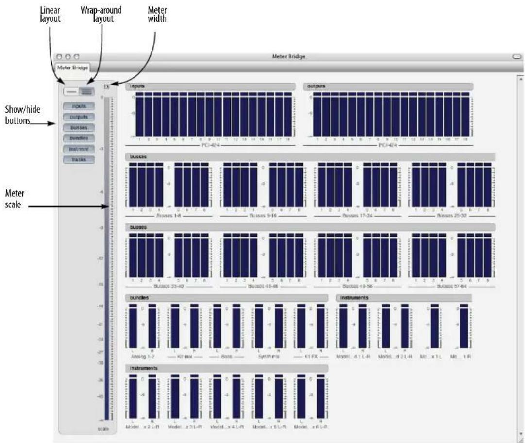
Figure 73-1: The Meter Bridge (showing the Wrap-around layout)
OPENING THE METER BRIDGE
To open the Meter Bridge, click its button in the Consolidated Window, or choose it from the Studio menu.
SHOWING AND HIDING METERS
Click the Show/Hide buttons (Figure 73-1) to display or hide the various types of audio paths. Option/Alt-click a button to display it and hide all others. Command/Ctrl-click to hide it and display all others.
LINEAR AND WRAP-AROUND LAYOUT
Click Linear layout (Figure 73-2) to see all of the meters together in one row (good for displaying them along the bottom or top of a Cinema display). Click Wrap-around layout to get a birds-eye view of all meters as shown (Figure 73-1).
METER WIDTH
The Meter Width control in the Meter Bridge (Figure 73-1) lets you adjust the width of the meters.
METER SCALE
Use the Scale control along the left side of the Meter Bridge window (Figure 73-3) to control the range of the meters. Drag the top and bottom of the blue range indicator to set the meter range as desired, as shown below:

Figure 73-3: Adjusting the range of the meters in the Meter Bridge.
INPUTS
The Inputs section displays all available hardware inputs provided by the audio hardware drivers currently selected in the Configure Hardware Driver window (see Figure 4-1 on page 27 and "Configuring the hardware driver" on page 27 in the DP4 Getting Started Guide). The input level meters are always monitoring the hardware inputs, regardless of whether input monitoring is active on any inputs.
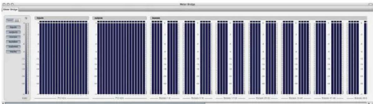
Figure 73-2: Linear layout.
OUTPUTS
The Outputs section displays all available hardware outputs provided by the audio hardware drivers currently selected in the Configure Hardware Driver window (see Figure 4-1 on page 27 and “Configuring the hardware driver” on page 27 in the DP4 Getting Started Guide). They show any signal that is reaching the hardware driver (which is then presumably passing on the signal to the actual hardware itself).
BUSSES
The Busses section displays all busses currently available in the Digital Performer mix engine. The number of busses shown is governed by the bus setting in the Configure Studio Settings window (see Figure 4-4 and “Configure Studio Settings” on page 33 in the DP4 Getting Started Guide). Busses are organized into banks of eight busses each.
BUNDLES
The Bundles section displays all output bundles, as created in the Outputs tab of the Bundles window (see Figure 14-1 on page 131 and chapter 14, "Bundles" (page 131) of this guide).
INSTRUMENTS
Enabling the Instrument button (Figure 73-1 on page 885) displays meters for the outputs that are mapped to your Instrument Bundles (multiple outs). The main output of your instruments are only viewable via the Tracks button.
TRACKS
The Tracks section displays an output level meter for each audio track in the currently play-enabled sequence. This meter is governed by the input monitor state of the track and generally matches the behavior of the track's level meter in the Mixing Board. For example, if you wish to monitor an audio track's input in the Meter Bridge, enable input monitoring for the track.
CLIPPING
Meter Bridge level meters turn red for a few seconds after clipping occurs to alert you that the signal has recently clipped. After a few seconds, they return to green. If they remain red for longer than a few seconds, this means that clipping is repeatedly occurring.
Retain clip
If the Retain Clip setting in the Audio Monitor ("Retain clip" on page 269) is enabled, then the red clip indicator at the top of each level meter will remain illuminated for a few seconds after clipping occurs.
Clearing the clipping indicators
Click an indicator to clear it. Double-click it to clear all indicators, or choose Clear All Clipping Indicators from the Studio menu.
Part 8
Processing
CHAPTER 74 Effects Window
OVERVIEW
The Effects window is a like a virtual effects rack for real-time, non-destructive MIDI and audio effects and virtual instruments. It displays all of the controls for a given effect on a given insert on a certain track. You can quickly and easily switch the effect, insert, and track you are viewing in the Effects window at any time.
The Effects window settings modify the track's playback only. The original data in the track is not changed. As a result, effects settings can be adjusted or turned off (bypassed) at any time.
This chapter provides general information about the Effects window. For details on using audio effects, MIDI effects, and virtual instruments, see chapter 75, “Audio Effects Processing” (page 897), chapter 76, “MIDI Effects Processing” (page 911), and chapter 17, “Instrument Tracks” (page 155).
Effects Window Quick reference .....891
Opening and Closing the Effects window .....893
Bypassing an effect....893
Saving, loading, and editing presets....893
Editing Effects....895
EFFECTS WINDOW QUICK REFERENCE
Below are the basic controls in the Effects window. The controls for each specific effect will, of course, vary.

Figure 74-1: The Effects window.
Window Target menu: This menu is used to change the sequence or V-Rack that the Effects window is showing. The name of the selected sequence or V-Rack is displayed.
Track menu: This menu is used to change the track that the Effects window is showing. The name and track type icon of the selected track is displayed.
Insert menu: This menu is used to change the insert that the Effects window is showing. The name of the selected insert is displayed.
When the Insert menu is open, all inserts for the track are shown, with each occupied insert also including the name of plug-in loaded in that insert.
Plug-in chooser/menu: The Plug-in chooser/menu is used to change the plug-in for the selected insert. The name of the selected plug-in is displayed.
Bypass: Temporarily disables the plug-in.
Automation menu: This menu is used to change the automation play-enable/record-enable state and automation mode for the track the effect is on.
Preset menu: This menu is used to save and recall presets. The name of the currently loaded preset is displayed. If you have made changes to the plug-in after loading a preset, the name becomes italicized to indicate that the preset's settings have been altered.
Learn Controller: Lets you assign a knob, slider or button from an external MIDI controller to a parameter in the plug-in window for MIDI remote control (“MIDI Learn”). See “Attaching a MIDI controller to plug-in parameters” on page 906.
Snapshot button: Takes an automation snapshot of the settings in the plug-in window. See “Taking an automation snapshot of plug-in parameters” on page 906.
Effect-specific controls: Controls for the specific plug-in are displayed here. These will be different, depending on the selected plug-in.
Effects window mini-menu
The Effects window mini-menu contains the following commands:
Floating: When checked, this menu item causes the window to stay in front of all other windows.
Float Effects by Default: When checked, plug-in windows are set to float when they are first opened. This is the same setting as the global preference (“Plug-in windows float above other windows by default” on page 904).
V-Rack Edit: Use the V-Rack Edit command to toggle between the current sequence and the last viewed V-Rack. You can also use its default key binding, Command/Ctrl-Shift-V.
OPENING AND CLOSING THE EFFECTS WINDOW
Opening the Effects window
There are several ways to open the effects window:
■ Choose Effects from the Project menu (or press Shift-F)
■ In the Mixing Board, choose an effect from any insert menu, or double-click an insert that already has an effect
■ For virtual instruments, double-click the track name in the Tracks Window.
You can have many Effects windows open at once, if you'd like.
Choosing a new effect for an insert
To choose an effect for an insert, select the desired effect from the Mixing Board insert. (See "Choosing a plug-in for an insert" on page 829). When creating a new effect, Digital Performer uses the most recent settings for that effect. For example, if you tweak quantize parameters on one track until they are just right, adding the quantize effect to another track will initially apply the same settings.
Floating effects windows
Effects windows can be made to “float” (stay in front of) other windows. This can be done on a per-window basis by checking the Floating mini-menu item of the Effects window itself. There is also a global preference to make all newly opened effects windows float. See “Plug-in windows float above other windows by default” on page 904.
Closing the Effects window
You can close the Effects window by:
■ Clicking its close button
■ With the standard 'Close window' key binding (Command/Ctrl-W)
■ With the Window menu > Close command
Hold Shift and Option while closing an Effect window in any of those ways to close all open Effect windows.
BYPASSING AN EFFECT
An effect can be bypassed by clicking the Bypass button in the Effect window. As a shortcut, you can bypass an effect directly in the Mixing Board by Option/Alt-clicking the effect insert with the finger cursor.
SAVING, LOADING, AND EDITING PRESETS
Presets are found in the Preset menu in the Effects window when the desired effect is being displayed in the window. For example, when the Effects window is showing the Reverb plug-in, you'll see Reverb presets in the Preset menu.
The current preset
When you choose a plug-in preset from the Preset menu, the preset name is displayed in the Preset menu, as shown in Figure 74-2. It also gets a check mark next to the name when the menu is open. If no preset has been loaded, "None" is displayed.
If you modify the settings, the name of the preset will become italic to let you know that you are now working with a modified preset. If you like, you can save the modified preset as a new preset with the Save Settings Preset menu command.
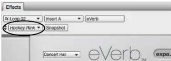
Figure 74-2: The current preset being used is displayed in the Preset menu. If you modify the settings of the effect, the preset name becomes italic to indicate that it is now modified.
Where presets are stored
Plug-in ‘factory’ presets are stored with the plug-in itself, so they are always available in any Digital Performer project.

Figure 74-3: Effects presets are located in the Effects window Preset menu. The menu only displays presets for the type of effect currently displayed in the Effects window. This example shows the eVerb plug-in and eVerb effects presets in the menu.
User presets are stored in separate folders for each plug-in, with each preset saved as a separate file. See “Saving plug-in settings as a user preset” below.
Saving plug-in settings as a user preset
To save the current plug-in settings as a preset, choose Save Settings from the Preset menu and type in the desired name. You can save the settings anywhere you wish on disk, but if you would like them to appear in the User Presets sub-menu, save them in the plug-in's presets folder. For example, presets for the Chorus plug-in would be stored here:
macOS /Library/Audio/Presets/Digital Performer/Chorus
Windows User\Documents\MAS Presets\MOTU\Chorus
If it is saved in this location, the new preset appears in the User Presets sub-menu.
Use the Show Presets in Finder/Explorer mini-menu command to go to the folder where user presets are stored for a plug-in. There, you can rename, duplicate, delete, etc. your preset files.
VST and Audio Unit presets
Some VST and Audio Unit plug-ins have the ability to save presets as a standard preset file on disk. Digital Performer supports these preset files. You can save them and load them in the same way as MAS plug-in presets, including the ability to drag and drop them to inserts in the Mixing Board.
Loading plug-in user presets
To load a user preset, choose it from the User Presets sub-menu in the Presets menu. Like clippings, user presets can also be dragged and dropped from the Finder or Explorer directly to inserts in the Mixing Board.
Changing a preset
To change an existing preset:
1 Choose the preset.
2 Modify it as desired.
3 Choose Save Preset from the Presets.
4 Save it with the same name. An alert dialog will confirm that you wish to change the existing preset.
Accessing user presets in other projects
Because user presets are stored independently from Digital Performer documents or the Digital Performer application itself, they automatically appear in projects other than the one in which you created the preset. You can also drag and drop them from their folder into any project at any time.
Storing and recalling presets as clippings
You can save and recall presets—and even groups of presets—as clippings. For details, see “Drag & drop plug-ins” on page 846.
Next/Previous Preset
You can quickly cycle through the available presets by:
■ Click the Next Preset/Previous Preset buttons (Figure 74-1 on page 891)
■ Choosing Next Preset/Previous Preset from the Preset menu
■ Using the Next Preset/Previous Preset key commands (Shift-Control/Win-equal and Shift-Control/Win-minus)
'Compare' Preset menu item
The Compare Preset menu item lets you compare a modified preset with the original, unmodified preset. You can freely switch back and forth between them to make a thorough A/B comparison.
When you first call up a preset from the Effects window Presets menu (either a factory preset or a user preset you created), the Compare menu item is grayed to indicate that the preset is currently unmodified.
As soon as you modify a plug-in parameter, the Compare menu item becomes ungrayed, indicating that the preset has been modified.
If you now choose Compare, it becomes checked, and the original preset settings are restored. In addition, your modified settings are stored by the Compare feature, ready for recall.
If you choose the Compare menu item again, it becomes unchecked, and your modified preset is restored. You can then freely switch back and forth between the original preset (checked) and the modified preset (unchecked).
Here is a summary of the compare feature:
Compare mini-menu item: Meaning:
Grayed Unmodified preset (or no preset)
Active (not grayed) Modified preset is active.
Checked Original preset is active.
EDITING EFFECTS
The controls provided for the effect itself depend on the plug-in. Refer to the documentation included with the plug-in for information on how to edit the plug-in. For information on automation plug-ins, see chapter 71, “Mix Automation” (page 851).
CHAPTER 75 Audio Effects Processing
OVERVIEW
An audio effects plug-in is a piece of peripheral software (developed by MOTU or another company) that can be used from within Digital Performer. Digital Performer serves as a host program for the plug-in, allowing you to apply its processing to your audio. Depending on the type of plug-in, you can either use the plug-in as an offline operation, selecting individual soundbites and then choosing the plug-in from the Audio menu, or you can apply it to an entire track as a real-time insert for the track in the Mixing Board.
Native plug-in processing....897
Real-time versus rendered effects .....898
File-based plug-in processing....898
Working with MAS plug-ins....899
Working with VST and Audio Unit plug-ins.....900
Organizing plug-ins ....901
Audio plug-in preferences....901
Using effect presets....904
Busing, master faders & aux tracks....904
Monitoring system performance .....904
Monitoring Effect Performance....904
Copying and pasting effect settings .....906
Plug-ins from other companies....906
Plug-in automation....906
Attaching a MIDI controller to plug-in parameters .....906
Tempo-locked effects....907
Side chain inputs....907
Channel configurations....907
Multiple audio outputs....907
Making a real-time plug-in effect permanent....907
Digital Performer plug-ins....908
Digital Performer virtual instruments....909
MOTU Instruments Soundbank....909
NATIVE PLUG-IN PROCESSING
Almost all MOTU Audio System plug-in effects can be processed dynamically during playback. They do not require extra hardware installed inside your computer because their processing is handled by the computer itself (referred to as native processing). Digital Performer includes dozens of MOTU Audio System plug-ins, from basics (such as 8-band parametric EQ, reverb, and dynamics) to vintage gear emulations to exotic forms of processing that are unique to Digital Performer. DP also includes virtual instruments. See “Digital Performer plug-ins” on page 908 for a list, and consult the separate Digital Performer plug-ins guide PDF in the Help menu for complete information about each plug-in.
Many third-party plug-ins are also available.
The amount of effects processing you can apply at one time has no inherent limit in Digital Performer. Instead, it depends on how fast your computer is: the faster the computer, the more real time effects you can use simultaneously.
Using effects plug-ins
Applying audio effects plug-ins to your audio tracks is straightforward: just choose the desired plug-in from one of the inserts for the track in the Mixing Board as shown in Figure 75-1 on page 898. Once you choose the effect (either from the plug-in chooser window or the menu provided), the Effects window appears with the settings for the plug-in. If the Effects window is already open, you can choose the effect from the menu provided at the top of the window.

Figure 75-1: Digital Performer provides real time effects plug-ins for audio tracks.
All of the features in the Effects window apply to audio effects, including using the Bypass button to temporarily remove the effect. See chapter 74, "Effects Window" (page 891) for details about the Effects window.
Automatic latency (delay) compensation
Digital Performer provides automatic latency compensation for all real-time audio plug-ins and virtual instruments. For details, see “Automatic plug-in latency (delay) compensation” on page 34 in the DP4 Getting Started Guide.
REAL-TIME VERSUS RENDERED EFFECTS
By default, Digital Performer transparently pre-renders audio output from virtual instrument tracks and audio tracks with plug-ins instantiated on them to dramatically reduce their CPU load. This is called pre-generation, and it greatly enhances Digital Performer's CPU performance, allowing you to instantiate many times the number of instruments and plug-ins that you would be able to run in real time.
Digital Performer seamlessly manages transitions between pre-generated audio and live audio as needed (such as when you record a virtual instrument live). In addition, virtual instruments are always available for preview activities, such as editing notes in the MIDI Graphic Editor or using a VI's on-screen keyboard.
To fine-tune the responsiveness of plug-ins and virtual instruments, go to Setup menu > Configure Audio System > Configure Studio Settings and adjust the Prime Milliseconds setting (see "Prime Milliseconds" on page 33 in the DP4 Getting Started Guide).
Pre-gen operation with 3rd-party plug-ins
MOTU works hard to ensure a high level of compatibility with 3rd-party virtual instruments and effects. There may be cases where pre-generation may not work as expected with a given 3rd-party plug-in. These cases should be reported to MOTU and the plug-in vendor so that compatibility can be fully established. In the meantime, you can run the plug-in or instrument in real time. To force a virtual instrument track into real-time operation, record-enable any MIDI track that targets the instrument. To force an audio track's effects into real time, the track can either be record-enabled or monitor-enabled. Alternately, the effect can be placed on an aux track, either in a chunk or a V-rack, with bussing used to access the effect. Aux track effects are always rendered in real-time.
FILE-BASED PLUG-IN PROCESSING
File-based processing does not occur in real time. Instead, it is applied similarly to Digital Performer's time-stretching features: you select soundbites to be processed (using one of Digital Performer's many methods for selecting soundbites), and then you apply the plug-in by choosing it from the Audio menu. A window appears for the plug-in, you make settings, preview the settings (if previewing is available),
and then click OK. When you do, a new audio file is created on your hard drive that consists of the original soundbites with the effect applied to them (plus any bite gain, if any has been applied to the original soundbite). Processing occurs in the background. All MAS plug-ins can be applied as file-based processing.
Reverse
There is one plug-in that is provided as a file-based plug-in only (in the Audio menu only): Reverse.
Previewing a file-based plug-in
When applying audio plug-ins from the Audio menu> Apply Plug-in sub-menu, you can preview the effect before applying it permanently:
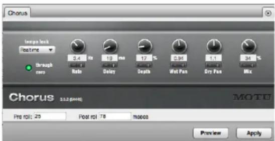
Figure 75-2: When you apply a plug-in as an offline operation from the Audio menu Plug-ins sub-menu, use the controls at the bottom of the window to preview the effect before applying it.
When you click the Preview button, the currently selected region loops continuously until you click the Stop button (or click anywhere outside the effect window). Parameter adjustments can be heard in real time as you change them. A preroll and postroll amount can be added to the beginning and end of the currently selected region for previewing purposes.
These previewing features can also be used for VSTs and Audio Units being applied as region operations.
To adjust the volume for previewing, use the Audition volume preference. See “Audition volume” on page 95. Also see “Specifying audio output for auditioning” on page 338.
WORKING WITH MAS PLUG-INS
Digital Performer can host MOTU Audio System (MAS) plug-ins. The MAS specification is a plug-in standard developed by MOTU that has been adopted by audio plug-in developers to optimize their products for use with Digital Performer. You can install MAS plug-ins on your computer and use them from within Digital Performer. The plug-in may also be supplied and installed in other plug-in formats as well for use with other host applications.
Installing MAS plug-ins
Digital Performer looks for third-party MAS plug-ins in these locations on your computer's hard drive:
Platform Path
macOS startup disk/users/current user/library/
audio/plug-ins/MAS
and
startup disk/library/audio/plug-ins/MAS
Windows* C:\Program Files\Common Files\MOTU\ Plug-ins\MAS
*If you are running the 32-bit version of DP on a 64-bit Windows system, the root of the path is: C:\Program Files (x86).
Digital Performer's included MAS plug-ins and instruments are not stored in the locations shown above. Instead, they reside inside the Digital Performer application bundle. This ensures that they are always compatible with the version of Digital Performer you are using. If older versions of DP's included MAS plug-ins are present in the macOS or Windows directory shown above, they will be ignored.
MAS plug-ins in macOS
For macOS, the user library directory refers to the user who is currently logged in to macOS.
Depending on how they were installed, plug-ins for Digital Performer are placed in one of the two locations shown above. If plug-ins are installed into the user library directory, they are installed for the user who is currently logged in to macOS at the time of installation.
Organizing MAS plug-ins in MacOS
You can organize the plug-ins across the system and user library directory locations as you prefer, with the following rules in mind:
- Plug-ins are bound to log-in access. For example, plug-ins that are placed in a user directory are available only when that user is logged in. This allows you to maintain different sets of Digital Performer plug-ins in multi-user environments.
■ Never duplicate a plug-in across the system and user directories (although you could duplicate a plug-in across multiple user directories, since only one user directory is active at a time).
■ You can organize plug-ins into folders, as explained in the next section.
WORKING WITH VST AND AUDIO UNIT PLUG-INS
Digital Performer can host VST plug-ins (VST2 or VST3) on both Mac and Windows, and Audio Unit (AU) plug-ins on MacOS. The VST and AU specifications are a plug-in standards that are widely adopted by music and audio software developers. You can install VSTs and AUs on your computer, and use them from within Digital Performer or other host applications that support them.
Installing VSTs and AUs
Digital Performer looks for VST and AU plug-ins in these locations on your computer's hard drive:
Platform Format Path
| MacOS AU Startup disk/Users/Current user/Library/Audio/Plug-ins/ComponentsandStartup disk/Library/Audio/Plug-ins/Components | |
| MacOS VST2VST3 | Startup disk/Users/Current user/Library/Audio/Plug-ins/VSTandStartup disk/Library/Audio/Plug-ins/VST |
| Windows* VST2VST3 | C:\Program files\Vstplug-ins\andC:\Program files\Steinberg\VstPlugins\andC:\Program files\Common Files\VST2orC:\Program files\Common Files\VST3 |
*If you are running the 32-bit version of DP on a 64-bit Windows system, the root of the path is: C:\Program Files (x86).
For MacOS, the user library directory refers to the user who is currently logged in to macOS X. If AU plug-ins are installed into the user library directory, they are installed for the user who is currently logged in to macOS X at the time of installation.
Third-party plug-in compatibility
Audio plug-in specifications continue to evolve, and developers are modifying and improving their plug-ins on an on-going basis to conform to each specification as it develops. MOTU has worked closely with many developers to ensure
compatibility and smooth performance. Always try to stay current with the latest versions of the plug-ins you use.
Plug-in examination
When you run Digital Performer for the first time, or after installing one or more new plug-ins, DP examines them during the loading process, checking them for problems. On MacOS, DP will first ask you to choose a primary external plug-in format (VST2, VST3 or AU) to examine and use as your preferred format (see “Primary external plug-in format (Mac only)” on page 904). This process may take a few minutes, depending on the nature and quantity of the plug-ins installed in your system. Each plug-in is examined only once, the first time it is loaded by Digital Performer. On subsequent launches, plug-ins that have already been examined will not be examined again. If a problem is detected with a particular plug-in, it will not be loaded for use in DP to prevent crashing and other serious problems.
You can choose to skip the examination of a particular plug-in, in which case it is not loaded and will not be available for use in that particular session. Skipped plug-ins can be examined later, the next time you launch Digital Performer or in the Plug-in Manager (see below).
If you wish to completely remove a plug-in so that it will not be examined or loaded, simply remove it from the folder where it is installed.
If a problem is detected with a particular plug-in, it will not be loaded for use in Digital Performer to prevent crashing and other serious problems. In the event that problems are found, the plug-in will be disabled and will not be loaded by Digital Performer. Contact the developer for information about updates for the plug-in.
For more information on managing third-party plug-ins, see “Audio plug-in preferences” below.
Using VSTs and AUs
Digital Performer supports two basic varieties of VSTs and AUs: effects plug-ins and virtual instruments. The effects plug-ins operate as described in this chapter. Just choose them from the desired effect insert and you are ready to go.
AU virtual instruments work as described in chapter 17, "Instrument Tracks" (page 155).
For details about using plug-in presets, see "VST and Audio Unit presets" on page 894.
ORGANIZING PLUG-INS
Digital Performer's plug-in chooser provides flexible and convenient plug-in organization and browsing. For details, see “Choosing a plug-in for an insert” on page 829.
AUDIO PLUG-IN PREFERENCES
To access Digital Performer's audio plug-in preferences (Figure 75-3), go to Preferences in the Digital Performer menu (macOS) or Edit menu (Windows) and click Audio Plug-ins in the list. These settings allow you inspect, enable, disable and otherwise manage the audio plug-ins installed in your system.

Figure 75-3: Audio plug-in preferences.
When you change any settings in the audio plugin preferences pane (except for the Ramp event density setting, see below), the MOTU Audio System must restart to apply your changes. You will be prompted to do so when closing the Preferences window, or when switching to another preference pane.

The plug-in preferences only apply to operation under the MOTU Audio System; when Digital Performer is operating under MIDI Only mode, the plug-ins list display will be empty.
Plug-ins list
All MAS, VST and Audio Unit plug-ins installed in your system and available to Digital Performer will be listed in this preference pane, with the plug-in format shown to the right of each plug-in. Use the search field to quickly locate a particular plug-in.
Each plug-in has a checkbox next to it. When the box is checked, the plug-in is enabled; when unchecked, the plug-in is disabled. Disabled plug-ins will not be loaded and will not appear in your audio plug-in lists in the Mixing Board or Audio menu > Apply Plug-in sub-menu (or in the case of instrument plug-ins, under the Project menu > Add Track > Instrument Track sub-menu).
You can also enable or disable multiple plug-ins simultaneously by selecting them and using the Enable and Disable buttons. Shift-click in the plug-in list to select a range of plug-ins, or Command/Ctrl-click to select non-contiguous plug-ins.
Examining VSTs and Audio Units
As explained earlier in “Plug-in examination” on page 901, VSTs and Audio Units will be automatically examined the first time Digital Performer is launched after they are installed. The result of the examination is listed next to each plug-in. The possible results are:
■ Passed: The plug-in passed examination and is available for use.
■ Failed: The plug-in did not pass examination and will not be loaded.
■ Skipped: Examination of the plug-in was skipped and will be automatically reexamined the next time the MOTU Audio System is restarted.
■ Duplicate: Multiple versions of the plug-in exist; for example, both a VST and MAS version exist. The MAS version is loaded.
- Non-primary: Indicates that the plug-in is not the primary format chosen in the preferences (Figure 75-3). See “Primary external plug-in format (Mac only)” on page 904.
If you wish to reexamine a plug-in or plug-ins, select the desired plug-ins and press the Reexamine button.
Plug-ins with multiple versions (formats)
Some plug-ins are supplied (and installed into your system) in several plug-in formats. For example, you might see both a VST and AU (or MAS) version of the same plug-in in the list. By default, one of the formats is enabled and the other is disabled and labeled either Duplicate or Non-primary. You can manually switch formats by unchecking and checking the boxes next to each plug-in as needed.
DP allows both AU and VST versions of the same plug-in to be activated at the same time. While this may be useful in some circumstances, it may make it hard to tell which format you are
using. In the case of some plug-ins, activating both formats can cause problems with their operation. To avoid confusion or operational issues, only enable one format or the other.
Plug-in sets
Plug-in sets (Figure 75-4) are custom collections of enabled audio plug-ins. Loading a plug-in set will enable only a specific subset of your plug-ins.
To choose a plug-in set, select it from the plug-in set menu. The chosen plug-in set will be displayed, but its plug-ins will not be loaded until you restart the MOTU Audio System.
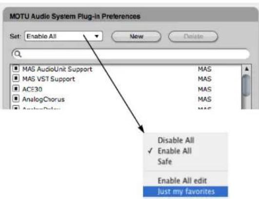
Figure 75-4: plug-in sets.
Enable All
When you choose the Enable All plug-in set (Figure 75-4), all plug-ins (except ones that did not pass examination) are enabled. This is the default plug-in set.
Disable All
When you choose the Disable All plug-in set (Figure 75-4), all plug-ins (except for Digital Performer's included surround panner plug-ins) will be disabled.
Safe
When you choose the Safe plug-in set (Figure 75-4), only the plug-ins which are included with Digital Performer are enabled; all other plug-ins will be disabled.
Creating and deleting plug-in sets
To create a new plug-in set, click the New button, enter a name, and click OK. To delete a plug-in set, choose it from the plug-in set menu and click the Delete button. When Enable All, Disable All or Safe is chosen, the Delete button will be grayed out as these plug-in sets cannot be deleted.
Editing plug-in sets
To edit a plug-in set, choose it from the plug-in set menu, then enable or disable the desired plug-ins.
The Enable All, Disable All or Safe plug-in sets cannot be modified. If you attempt to enable or disable any plug-ins while one of them is selected, you will be prompted to create a new set. You can then edit the new plug-in set just as you would any other.

Selecting a plug-in set at startup
Hold the Option/Alt key while launching Digital Performer to bring up a dialog which allows you to choose the plug-in set which will be loaded:

Ramp event density
The Ramp event density option (Figure 75-3) sets the default density when writing ramp automation for plug-ins.
Primary external plug-in format (Mac only)
The Primary external plug-in format option is for MacOS only and determines the format of the plug-ins that DP will examine and enable by default. Choose Audio Units if you have a large number of existing DP projects that use AUs, and you don't need to transfer DP projects to and from Windows systems. Choose VST2 or VST3 to increase the cross-platform compatibility of your projects. This setting can be changed at any time.
Plug-in windows float above other windows by default
When checked, the Plug-in windows float above other windows by default preference causes newly opened plug-in windows to appear in front of all other windows. This allows you to work in other DP windows without plug-in windows disappearing behind them. This preference only affects new plug-in windows when they are first opened. Once a plug-in window is open, it can float or not, as determined by its Floating mini-menu setting (see “Effects window mini-menu” on page 892).
USING EFFECT PRESETS
Many audio effect plug-ins provide factory presets, and you can also save and recall your own presets. This works in the same way as it does with MIDI effects and virtual instruments. See “Saving, loading, and editing presets” on page 893.
BUSING, MASTER FADERS & AUX TRACKS
The MOTU Audio System provides a flexible virtual mixing environment. You can take advantage of features like the internal audio buses to apply effects as needed and even conserve your computer's processing power by busing multiple tracks to the same effect insert. You can also apply effects to aux tracks and master faders as pre or post fader effects. For details, see chapter 70, "Mixing Board" (page 821) for more ideas about how to work with real time audio effects within Digital Performer's virtual mixing environment.
MONITORING SYSTEM PERFORMANCE
Plug-ins can require a significant amount of CPU bandwidth (your computer's processing power). The speed of your computer determines how many effects you will be able to apply at one time. Use the Audio Performance window to keep an eye on how much of your CPU bandwidth you are using up with your plug-ins.
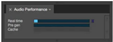
Figure 75-5: The 'Real time' meter in the Audio Performance window shows you how much of your computer processing power is being used by the MOTU Audio System and the real-time effects plug-ins that are currently active. If any of the meters reach yellow, you should consider reducing the number of plug-ins you are using.
The Audio Performance window can be opened by choosing Audio Performance from the Studio menu.
For tips on conserving the processing resources of your computer, see “Optimizing performance” on page 32 and “More ways to enhance performance” on page 35 in the DP4 Getting Started Guide.
MONITORING EFFECT PERFORMANCE
The Effect Performance window (Studio menu) monitors the processing load of all currently instantiated virtual instruments and effects plug-ins (Figure 75-6). It can help you identify and manage plug-ins that impose high processing demands on your computer.
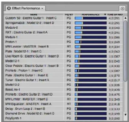
Figure 75-6: Effect Performance window.
List sorting
Click the column headings in the Effect Performance list (Figure 75-6) to sort by name, performance, etc. Each heading can sort from top to bottom or bottom to top (or high to low, low to high, etc.) Click the heading to toggle the sort order. When sorting by Performance or Time of Max, the list reorders on the fly, as demand fluctuates during playback.
PG/RT
The PG/RT column (Figure 75-6) shows whether the plug-in is running in real time (RT) or pre-gen (PG) mode. If you hover the cursor over the RT indicator for a plug-in, you'll see a tool tip that explains why the plug-in is running in real time. If a real-time (RT) plug-in displays exceptionally high performance load, try running it in pre-gen (PG) mode.
Performance meter and Time of Max
The Performance meter (Figure 75-6) provides a visual representation of each plug-in's individual CPU load — essentially how hard it is working — as a percentage of the overall processing currently being handled by Digital Performer's audio engine. Above the blue meter, there is a maximum peak load indicator shown as a colored line. The color of the line depends on which DP theme you are using (shown in yellow in Figure 75-6). The Time of Max column displays the sequence timeline location where this maximum peak occurred, which can help identify sections of the sequence that are particularly demanding from a CPU standpoint, especially for virtual instruments. Use the Clear Max mini-menu command to clear all max peak indicators and the Time of Max column.
Individual versus Coalesced
The Effect Performance mini-menu provides two views for this window: Individual and Coalesced. In Individual mode (the default setting) each effect is displayed separately in the list (Figure 75-6). In Coalesced mode, processing overhead is combined by effect type (Figure 75-7). For example, all instances of iZotope Ozone would be gathered into a single item in the list. You can freely toggle between these two modes. Two columns show combined average CPU load and peak percent of overall CPU load.

Figure 75-7: Coalesced mode.
The Time of Max column is not available in Coalesced mode because each line in the Effect Performance list may represent multiple instances of plug-ins which have maximum CPU peaks at different times.
Tips for reducing plug-in performance load
For pre-gen virtual instruments, make sure the MIDI track feeding the instrument is not record-enabled (which temporarily puts them in RT mode).
Some instrument plug-ins, such as MachFive and Omnisphere, can host multiple instruments in one instance of the plug-in. You can reduce overall performance load by creating a separate instance of the plug-in for each instrument (i.e. a separate instrument track), rather than loading multiple instruments into one instance.
COPYING AND PASTING EFFECT SETTINGS
As with MIDI effects, you can copy and paste audio effect parameters from one insert to another. Just choose Copy from the Edit menu while a specific insert's effect is being displayed, switch to a different insert with another effect, and choose Paste. Even if the destination plug-in is completely different, any parameters of the same kind are pasted.
PLUG-INS FROM OTHER COMPANIES
The three plug-in architectures (MAS, VST and AU) are open systems. Many other companies have developed plug-ins that are compatible with these plug-in formats, running in real time on your computer with no extra hardware required.
PLUG-IN AUTOMATION
Plug-ins can be automated in real time. For complete information, see chapter 71, “Mix Automation” (page 851).

Figure 75-8: Click the Auto (automation) button to access the automation settings menu for this track. The menu has checkable items that enable/disable automation playback and recording. It also lets you choose the current automation mode for the track.
TAKING AN AUTOMATION SNAPSHOT OF PLUG-IN PARAMETERS
Use the automation snapshot button (Figure 74-1 on page 891) to capture the current settings of the plug-in in the track at the current playback location. For more information about snapshots and automation, see “Snapshot automation” on page 864.
ATTACHING A MIDI CONTROLLER TO PLUG-IN PARAMETERS
The Learn Controller command (Project menu> Consoles) allows you to map controls on your MIDI controller to plug-in parameters.
Learn Controller can also be used to map your MIDI controller to Mixing Board sends and send pan, as explained in “Attaching a MIDI controller to sends or send pan” on page 845.
To attach a MIDI controller :
1 Choose Project menu> Consoles> Learn Controller, or click the Learn Controller icon at the bottom of the plug-in window (Figure 74-1 on page 891).
2 Click the desired plug-in parameter.
3 Move, turn or press the desired control on your MIDI device. To cancel the operation before completing it, choose Learn Controller (or click the icon) again at any time during the process.
This process creates a MIDI Custom Console with a value box object in it that establishes the connection between the external MIDI controller and the plug-in parameter. You can further inspect and adjust how the parameter responds to the controller by double-clicking the value box object in the console, which opens the Control Assignment window (Figure 56-3 on page 714).
TEMPO-LOCKED EFFECTS
Many plug-ins allow you to lock certain parameters, like their LFOs, to the tempo of your sequence. This allows the effect to stay in sync with the beat of your music, even if there are tempo changes.
For details on tempo-locking effects included with Digital Performer, see “Tempo lock” on page 8 in the DP Plug-in Guide. For details on tempo-locking third-party effects, refer to their documentation.
CHANNEL CONFIGURATIONS
Digital Performer allows you to configure your system with a combination of mono, stereo and surround signal paths. For more details, see "Channel configurations" on page 8 in the DP Plug-in Guide.
SIDE CHAIN INPUTS
A side chain input allows you to route any audio directly into the plug-in itself to control a parameter with the side chain input signal. It appears in a plug-in window as a menu that shows a list of Digital Performer's virtual busses. For many MAS plug-ins, the menu appears within the plug-in itself:

Figure 75-9: The side chain input in a MAS plug-in (Dynamics).
For some plug-ins, the side chain input menu appears in the Effects window:

Figure 75-10: The side chain input in the Effects window.
To use the side chain input, choose an audio input or bus from the menu and then route a signal to the bus from any source you want in Digital Performer's mixing environment (a track, a live aux input, etc.). Several included plug-ins have side chain inputs, including Dynamics, Ring Modulator, and Multimode Filter. Refer to chapter 1, "Audio Effects Plug-ins" (page 7) in the DP Plug-ins Guide.
MULTIPLE AUDIO OUTPUTS
Some effects plug-ins provide multiple audio outputs. You can access them in the Instruments tab in the Bundles window, just as with virtual instruments. For details, see “Multiple audio outputs” on page 158.
MAKING A REAL-TIME PLUG-IN EFFECT PERMANENT
All real-time plug-ins that appear in the Mixing Board window effects inserts also appear in the Audio menu > Plug-ins sub-menu. To apply them, you can select audio in any window you prefer.
DIGITAL PERFORMER PLUG-INS
For details on the following plug-ins included with Digital Performer, see chapter 1, “Audio Effects Plug-ins” (page 7) in the DP Plug-ins Guide (Help menu).
■ ACE-30
■ Analog Chorus
■ Analog Delay
■ Analog Flanger
■ Analog Phaser
■ AutoPan
■ Bass Manager
■ Buffy
■ Calibration
■ Chorus
■ Clear Pebble
■ Custom '59
■ D Plus
■ DC Notch
■ De-Esser
■ Delay
■ Delta Fuzz
■ Diamond Drive
■ Dynamic Equalizer
■ Dynamics
■ Dyna Squash
■ Echo
■ Ensemble Chorus
■ eVerb
■ FET-76
■ Flanger
■ Hardware Insert
■ Hi-Top Booster
■ Intelligent Noise Gate
■ Invert Phase
■ Live Room B
■ Live Room G
■ Live Stage
■ MasterWorks Compressor
■ MasterWorks EQ
■ MasterWorks FET-76
■ MasterWorks Gate
■ MasterWorks Leveler
■ MasterWorks Limiter
■ MegaSynth
■ MicroB
■ MicroG
■ MS Decoder
■ MultiFuzz
■ Multimode Filter
■ MX4
■ ParaEQ
■ Pattern Gate
■ Phaser
■ Plate
■ PreAmp-1
■ Precision Delay
■ ProVerb
■ Quan Jr
■ Reverb
■ Reverse
■ Ring Modulator
■ RXT
■ SMPTE-Z
■ Soloist
■ Sonic Modulator
■ Spatial Maximizer
■ Springamabob
■ Subkick
■ Tremolo
■ Trigger
- Trim
■ Tube Wailer
■ Tuner
■ Über Tube
■ Wah Pedal
DIGITAL PERFORMER VIRTUAL INSTRUMENTS
For details on the following virtual instrument plug-ins included with Digital Performer, see chapter 2, “Instrument Plug-ins” (page 97) in the DP Plug-ins Guide (Help menu).
■ Bassline
■ PolySynth
■ Nanosampler
■ Modulo
■ Model 12
■ MX4
■ Proton
MOTU INSTRUMENTS SOUNDBANK
The MOTU Instruments soundbank provides approximately 5.5 GB of multi-sample instruments, loops, phrases, and synth instruments. To use the MOTU Instruments soundbank, you load it into the free UVIWorkstation application, which runs either as a standalone virtual instrument or as an instrument plug-in within Digital Performer.
For details see chapter 3, “MOTU Instruments Soundbank” (page 133) in the DP Plug-ins Guide (Help menu).
CHAPTER 76 MIDI Effects Processing
OVERVIEW
Digital Performer provides many real-time, non-destructive MIDI effects plug-ins. This chapter discusses the specifics of each MIDI plug-in.
For general information about the Effects window, see chapter 74, “Effects Window” (page 891). For general information about using plug-ins, organizing them, creating and managing user presets, and other related topics, see chapter 75, “Audio Effects Processing” (page 897).
Change duration .....911
Change velocity 911
DeFlam....912
Echo and Arpeggiator ....912
Groove Quantize ....916
Humanize....916
Invert Pitch....917
Quantize .....917
Reassign Continuous Data....918
Remove Duplicates....918
Time Shift 918
Transpose....918
CHANGE DURATION
The Change Duration plug-in can non-destructively modify the durations of MIDI notes during playback. It has the same settings as the Change Duration command in the Region menu (page 625).

Figure 76-1: The Change Duration effects processor.
Change Duration modifies the duration without changing the placement of attack times. This means that the amount of time a note is “on” or sounding can be changed without affecting its actual rhythmic placement in relation to other notes and events. The Change Duration command is useful for changing the articulation or space between notes. You can make note events sound connected or separate in relation to each other, for example. It also provides some useful utility functions.
For more information, see “Change Duration” on page 625.
CHANGE VELOCITY
The Change Velocity plug-in can non-destructively modify the on and/or off velocities of MIDI notes during playback. It has the same settings as the Change Velocity command in the Region menu (page 622).
For the Compress/Expand option, the graph shows the result of the compression/expansion settings. A diagonal line from lower left to upper right represents no compression or expansion. Drag the Threshold, Ratio and Gain handles to change their settings. The higher the ratio, the higher compression; ratios below 1 produce expansion. Gain allows you to raise or lower the overall level. Threshold sets a cutoff value, below which no compression or expansion will occur.

Figure 76-2: The Change velocity effects processor. Drag the handles to change the Threshold, Ratio and Gain settings.
DEFLAM
The DeFlam MIDI effects plug-in is a non-destructive version of the DeFlam region operation found under the Region menu (page 621).
DeFlam looks for groups of note that are very close together. When such a group is found, the average attack time of the group of notes is computed. All notes in the group are moved such that their attack times are aligned exactly to the average time.
The group of notes that is deflammed is determined by the tick value you specify. This creates a “window” of effectiveness. Groups of notes within that window will be deflammed.
For more information, see "DeFlam" on page 621.

Figure 76-3: The DeFlam effects processor.
ECHO AND ARPEGGIATOR
The Echo effect is similar to a traditional digital delay. It remembers material played in, then repeats it later on. There are some interesting differences, though. You are not restricted to simple fixed delays. In fact the “rhythmic pattern” used by the Echo for regenerating the material is completely customizable. Additionally, each repetition of the material can be sent to a different output assignment. Furthermore, a transpose effect is hooked into the Echo's feedback loop, allowing you to transpose on each repetition.
The Arpeggiator watches what notes are sounding (being held) and then arpeggiates them (plays them one at a time). The Arpeggiator gives you complete control over the rhythm and order in which the notes are played back. In addition, each arpeggiated note can be sent to a different output assignment.
Rhythmic patterns
Both the Echo and Arpeggiator effects are built around a flexible rhythmic architecture. In the Echo effect the Rhythm section determines how each event will be delayed. In the Arpeggiator it determines the rhythm that will be used for each arpeggiated note. Rhythms can be set up using one of three modes: Grid, Custom and Raw Ticks.
Grid: You will notice that the Grid mode settings are almost identical to the Quantize effects grid settings. They function in a similar fashion. You can set up rhythms consisting of any metric subdivision. You can “swing” the grid, and you can offset the entire grid by an arbitrary number of ticks. (For more info, see the section on the Quantize effect.) Rather than a check box for “Tuplets”, there is a popup menu. This menu lets you turn off the tuplet feature, turn it on (select Tuplet) or put the grid into “poly rhythm” mode (select Poly). The “Off” and “Tuplet” settings are identical in effect to checking or un-checking the Tuplet box in the Quantize effect. The Poly mode combines both sides of the tuplet expression (you will notice that the words “in the time of” change to “against”) to create a standard rhythmic interference pattern. For example if you pick Poly and choose 3 against 2 (eighth notes) you will hear both a straight eighth note pulse and a “3 in the
time of 2" pulse. Try different values to create interesting textures (5 against 3 is an interesting one).
Custom: This setting lets you define your own rhythmic patterns based on selected notes. You can make “Groove Echos”, arpeggiations based on melodic patterns, bizarre multi-tap echo effects — the sky’s the limit. To create a rhythmic pattern, just select some notes in a single track, enter a name, and press Learn.
When a pattern is learned, it is the time between note events that is remembered. Thus, if you select 4 notes, only 3 grid spaces will be learned (the distance from note 1 to note 2, 2 to 3 and 3 to 4). With this in mind, you may need to add an extra note at the end of your selection to delineate the final grid span.
Rhythmic patterns created in the Echo effect can also be used with the Arpeggiator effect. Rhythms can be loaded into Digital Performer from other files.
Raw Ticks: Simply lets you specify the echo or arpeggiation in raw ticks. This is handy for creating rhythms that are “off” from the main pulse of the music.
Echo Settings
Here is a brief explanation of each setting for the Echo effect:

Figure 76-4: The Echo effects processor.
Num Repeats: Sets how many times each event will be repeated. The number includes the first time you hear the note. (If you enter 4, and play a note, you will here that note a total of 4 times.)
Decay: An amount that will be subtracted from the velocities of note events each time they are regenerated. This lets you create echos that sound like they are fading out. You should coordinate this setting with Num Repeats so that the note stops repeating around the same time it finally fades out, otherwise you will be echoing almost silent notes.
Cycle through device group assignments: If you check this box and assign the track's output to a MIDI device group, each repetition of each event will be sent to a different assignment in the MIDI device group. For example, let's say that you have a track assigned to a MIDI device group with two devices in it (SC7 channel 1 and SC7 channel 2) and you have "Num Repeats" set to 4. When you play a note, the first repeat will go to SC7 channel 1, the second will go to SC7 channel 2, the third
will go to SC7 channel 1, and the fourth will go to SC7 channel 2. There are many ways to use this feature. Here are a few examples.
Create true echos including controller data. Normally, controllers and pitch bend are not echoed. This is because overlapping streams of controller data almost always lead to unpleasant results. "Cycle through device group assignments", however, lets you send each instance of the echo to a different MIDI channel, circumventing this problem. To use the echo in this way, set up a MIDI device group containing the same number of assignments (on the same device) as number of repeats. (For example, if you wanted a 4-repeat echo, you could make a MIDI device group on your SC7 on channels 1, 2, 3 and 4.) Each assignment should have the same patch set as its default. (You can create panning echo effects by setting the pan differently on each channel in the group. To do this, add a track assigned to each channel in the group (SC7 1, SC7 2, etc.), open the Mixing Board, show only those tracks, set the pan knobs appropriately, rewind to measure 1 and take a snapshot.) In this way, each echo goes to a different channel, and none of the controller information collides with previous data.
Create weird rhythmic and “cannon” effects by setting things up the same way as above, but then give each device in the group a different patch. You can have a Sax echo your piano line or a murky voice echo your synth lead. Adding percussion assignments creates interesting rhythmic accents to your echos. Experiment!
Feedback Transpose: Each time the echo processor regenerates a note event, it passes it through the Feedback Transpose effect. (If the Transpose Effect is set to “unity transpose”, i.e. C3 to C3, it has no affect.) You can use this to create all sorts of cascading note effects. Since the Transpose effect can use arbitrary Custom Maps, any sort of transpose is possible. For example, you could have your echos cascade up, while remaining in key. Or have each repetition of the echo jump to any arbitrary pitch. (Twisted!) Watch out for the Harmonize option, though. It can really chew through your polyphony in a hurry; it is best used only with short delays. See “Transpose” on page 918 for more info.
Here is a brief explanation of each setting for the Arpeggiator:
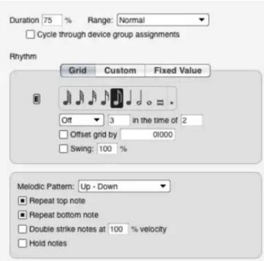
Figure 76-5: The Arpeggiator effects processor.
Duration: This sets the length of each arpeggiated note as a percentage of time until the next note. 100% makes each note last until the next note begins. 1% makes each note very short. Try using sustain pedal for legato effects.
Range: This lets you arpeggiate across a specified number of extra octaves. You can choose Normal (no additional octaves) or +1, +2, or +3 octaves.
Cycle through device group assignments: This is similar to the Echo effect setting, but it has no affect over controllers. The Arpeggiator always sends all controllers to all output assignments in the MIDI device group. When this option is
checked, each arpeggiated note will be sent to a different output assign. You can create all sorts of interesting effects with this. The tricks with panning mentioned in the Echo section also apply here. Try a MIDI device group with several slightly different guitar patches for a “League of Crafty Guitarists” in a box. Try a group consisting of several different horn patches, or percussion instruments. Great fun.
Melodic Pattern: This setting determines the order in which the held notes are played back. There are several built-in patterns. You can also define your own custom patterns.
Built-in patterns: In each of the following examples, assume a 6 note chord, with each note numbered 1 to 6, 1 being the lowest and 6 being the highest.
Up: plays the notes in order, starting with the lowest, and moving to the highest. Note order: 1,2,3,4,5,6.
Down: Plays the notes in order, starting with the highest and moving to the lowest. Note order: 6,5,4,3,2,1.
Up - Down: First plays Up, then plays Down: Note order 1,2,3,4,5,6,6,5,4,3,2,1
Down - Up: First plays Down, then plays Up: Note order 6,5,4,3,2,1,1,2,3,4,5,6
Staircase Up: Walks up the notes in a zig-zag pattern: Note order 1,3,2,4,3,5,4,6
Staircase Down: Walks down the notes in a zig-zag pattern: Note order 6,4,5,3,4,2,3,1.
Staircase Up - Down, Staircase Down - Up: Same idea as Up - Down and Down - Up.
Spiral In: Starting at the outside edges alternately walks into the center. Note order 1,6,2,5,3,4.
Spiral Out: Starting in the middle, alternately walks to the edges. Note order 4,3,5,2,6,1.
Spiral In and Out, Spiral Out and In You get the idea.
Random: Randomly picks the note order.
As Played: This option takes into account the order in which you play the notes of a chord and plays them back in the same order as played. The pattern is repeated for each additional octave (if any) specified by the Range option.
Chord Play: This option plays notes as repeated chords instead of arpeggios.
Custom Melodic Patterns: When custom is selected, the window expands to show controls similar to those for creating and picking Custom Rhythmic Patterns. To create a Custom Melodic Pattern, select some notes in a single track, enter a name, and press “Learn”. The Arpeggiator analyzes the selected note data and remembers the order that the pitches are in. This order is then applied to the notes that you hold down. Note that the built in patterns work well no matter how many notes you are holding down. This is not as true of Custom Melodic Patterns. Custom patterns work best if you play the same number of notes as were in the learned pattern. (Note: There currently is no way to edit or retrieve the patterns after-the-fact, so you should save your source notes somewhere so you can tweak and relearn later on.) You can use Custom Melodic Patterns to mimic all sorts of finger picking, and even strumming styles.
Repeat bottom/top note: These check boxes only apply to the following melodic patterns: Up-Down, Down-Up, Staircase Up-Down, Staircase Down-Up, Spiral In and Out, and Spiral Out and In. Therefore, these new check boxes are grayed out unless one of these patterns is chosen in the Melodic Pattern menu.
Double strike notes at ____% velocity: This option causes each note to be played twice. The on-velocity of the second note can be specified from 0-200% of the first note's velocity.
Hold Notes: This option causes notes to be held even after you release them. They remain held (and will continue to arpeggiate) until you release all notes and play a new note.
Applying the echo and arpeggiator effects as Region menu commands
Both the Echo and Arpeggiator effects are available as MIDI effects plug-ins in the Region menu, which allows you to render the effect permanently to a track. This is great for editing the effect further. For details, see “MIDI Effects Plug-ins” on page 632.
Fun things to do with the Echo and Arpeggiator effects
Add a Transpose effect before the Arp effect. (Apply Transpose in Insert A and Arpeggiator in Insert B). Set the Transpose effect to Harmonize and transpose an octave up or down. This doubles the notes sent to the Arp effect, and gives it more notes to play with.
Learn bits of your song, both as melodic patterns, and as rhythmic patterns. Mix and match for Arpeggiator and Echo effects that compliment the rhythm and melodies of your music.
Use the Arpeggiator with a drum kit. Set the rhythm to a Poly 3 against 2. Hold down a big clump of drum note. Try using different melodic patterns. (Random works great.)
Echo your Arpeggiator. Add an Echo effect after the Arpeggiator, and set it for a long delay. Set the Arpeggiator to play with a grid that has an interesting rhythmic relationship to the echo. For example, set the Arpeggiator to a straight eighth note grid an the Echo to Tuplets, 3 in the time of 2 [quarter note]. Now, set the Echo effect to 2 repeats, and transpose up an octave (C3 to C4) with the Feedback Transpose section.
The Arpeggiator effect uses the velocities of the notes that you played in its arpeggiation. This can be used to great effect. Play a clump of notes with a medium velocity, then strike a new note with force. The new note will stand out in the arpeggiation in an interesting fashion. If desired, add a Change velocity effect after it to keep the velocities in a normalized range.
GROOVE QUANTIZE
Groove Quantize is a real-time version of the Groove Quantize region operation found under the Region menu. For more information, see "Groove Quantize" on page 609.
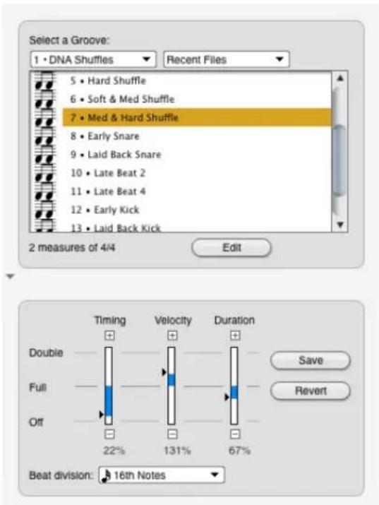
Figure 76-6: The Groove Quantize effects processor.
HUMANIZE
Humanize is a real-time version of the Humanize Region command found under the Region menu.
The Humanize command lets you add a “random” element—or “humanized” feel—to your music. With this command, you can randomize any combination of the following elements of your music:
■ Note placement
■ Note durations
■ Velocities
■ Pitches
■ Tempo
In addition, you can create a unique blend of these humanize elements and save it as a humanize style, which you can recall and use at any time. You can use the Humanize command to create arpeggiation effects, hi-hat (or other percussion instrument) grooves, and other dramatic musical effects.
For more information, see "Humanize" on page 618.
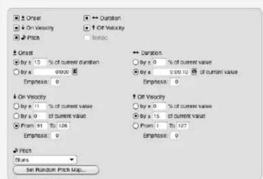
Figure 76-7: The Humanize effects processor.
INVERT PITCH
The Invert pitch processor allows you to specify an axis point around which your MIDI note data will be inverted. For example, if C3 is specified as the center pitch, C#3 will sound as B3 and B3 will sound as C#3. The Invert Pitch MIDI plug-in functions as a non-destructive version of the Invert Pitch region operation detailed in “Invert Pitch” on page 631.

Figure 76-8: The Invert Pitch effects processor.
QUANTIZE
The Quantize effects processor is identical to the Quantize command in the Region menu, except, of course, that it has no permanent effect on the data in the track. Since it only affects data upon playback, it can be adjusted and even turned off (bypassed) at any time. For details on Quantize options, see “Quantize” on page 603.
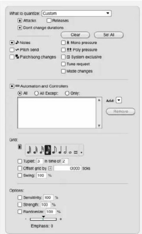
Figure 76-9: The Quantize effects processor.
REASSIGN CONTINUOUS DATA
This real-time effect is very similar to the Region menu command with the same name (page 637), except that it modifies only MIDI continuous data (but not audio volume, audio pan or audio plug-in automation).
As shown in Figure 76-10 below, notice that this plug-in can also generate registered and non-registered parameters (RPN's and NRPN's).

Figure 76-10: The Reassign Continuous Data MIDI plug-in, which can generate RPN and NRPN data.
REMOVE DUPLICATES
Remove Duplicates is a real-time plug-in that eliminates duplicate notes on the fly. This is useful for situations when quantization creates a 'chord' consisting of the exact MIDI note. Placing Remove Duplicates in line after Quantize helps eliminate this problem.

Figure 76-11: The Remove Duplicates effects processor.
TIME SHIFT
The Time Shift effects processor is identical to the Shift command in the Edit menu, except, of course, that it has no permanent effect on the data in the track. Since it only affects data upon
playback, it can be adjusted and even turned off (bypassed) at any time. For details on Shift, see "Shift" on page 585.

Figure 76-12: The Time Shift effects processor. Click the button circled above to change the time format used to specify the amount of time.
TRANSPOSE
Choose the type of transposition you would like: either by a single interval or using a custom transpose map you have created with Transpose command in the Region menu (page 594). With interval transposition, enter any interval you like in the value boxes provided by editing the pitch text box (type, drag up/down, or use MIDI entry). The specific pitches do not matter: the interval between them determines the degree of transposition. For example, to transpose an octave up or down, choose C4 or C2, respectively.
The Harmonize option causes the newly transposed data to be combined with the original data, so that they both play simultaneously.

Figure 76-13: The Transpose effects processor.
CHAPTER 77 Audio File Conversion
OVERVIEW
The Convert Audio File command in the Soundbites window mini-menu allows you to change the sample rate, sample format (bit depth), file format, and interleave format of an audio file or soundbite.
You can change:
■ sample rate: any sample rate between 1 kHz and 200 kHz
■ sample format: 16-bit integer, 24-bit integer, or 32-bit floating point
■ file format: Broadcast WAVE, AIFF, or Sound Designer II
■ interleave format: interleaved or deinterleaved
Like Digital Performer's other "constructive" DSP processes, these conversions can occur in the background.
Performing conversions....919
Converting the sample rate....919
Converting the sample format....920
Converting the file format....920
Converting the interleave format....920
Converting entire audio files....920
Soundbite replacement options....920
Automatic Conversions....920
PERFORMING CONVERSIONS
To open the Audio File Conversion window, select a soundbite or audio file and choose Convert Audio File from the Soundbite window mini-menu.

Figure 77-1: The Audio File Conversion dialog
Using the checkbox next to each section, each conversion operation can be turned on or off to perform any combination of operations.
CONVERTING THE SAMPLE RATE
Digital Performer uses a highly precise, efficient, and transparent sample rate conversion algorithm, with a 138 dB signal-to-noise ratio.
To sample rate convert some audio, select one or more soundbites in the Soundbites window and choose Convert Audio File from the Soundbites window mini-menu. The Audio File Conversion dialog appears.
Changing the recognized sample rate for an audio file
When checked, the Only change the file's recognized sample rate but do not process the file's audio option changes the sample rate attribute for the audio file, but it does not actually process or otherwise alter the audio data in the file. Use this command in situations where the sample rate being reported by the file (as listed in Digital Performer's Soundbites window, or the info window in other audio applications) erroneously does not match the actual sample rate of the audio contained in the file.
CONVERTING THE SAMPLE FORMAT
The Convert Sample Format section of the Audio File Conversion, as shown below in Figure 77-1, allows you to change the sample format of an audio file or soundbite. You can change to 16 bit integer, 24 bit integer, or 32 bit floating point. Like Digital Performer's other file-based "constructive" DSP processes, sample format conversion can occur in the background.
Dither
Digital Performer incorporates dither when converting to a lower bit depth— rather than truncating the extra bits — to ensure the smoothest possible conversion.
CONVERTING THE FILE FORMAT
In the File Format section of the Audio File Conversion window, you can convert the file format of your audio files between Broadcast WAVE, AIFF, and Sound Designer II. You can convert from any format to any other. Note that if a file's sample format is 32-bit floating point, when converting the file format to Sound Designer II the resulting file's sample format will be converted to 24-bit integer (32-bit floating point is not supported with Sound Designer II files).
CONVERTING THE INTERLEAVE FORMAT
Interleaved audio uses one file for all channels, whereas deinterleaved uses one file for each channel. In the Interleave Format section of the Audio File Conversion window, you can convert the interleave format of your audio files between interleaved and deinterleaved.
CONVERTING ENTIRE AUDIO FILES
When you choose a soundbite for conversion, you can choose between converting only the soundbite itself (the portion of the audio file that falls within the soundbite) or the entire parent audio file. If you will need to use other parts of a audio file (edge editing the converted soundbites, for example), you should choose to convert the whole file.
SOUNDBITE REPLACEMENT OPTIONS
In Digital Performer, sample rate and sample format conversion is a “constructive” editing process, which means that it always generates new audio files and preserves the original ones. Several options are provided to specify what to do with the old audio, and how to replace existing soundbites.
If the Replace soundbites and Convert entire audio file options are chosen, you may also enable the Move the original file to the trash option.
AUTOMATIC CONVERSIONS
Digital Performer can perform certain conversions automatically. For more information, see “Automatic Conversions” on page 89.
CHAPTER 78 Time-stretching and pitch-shifting
OVERVIEW
This chapter gives you a brief overview of Digital Performer's audio time-scaling and pitch-shifting capabilities. It then discusses the following important topics that are common to all of Digital Performer's Digital Signal Processing (DSP) tasks:
ZTX™ audio processing .....921
Selecting audio for processing....921
Editing MIDI and audio together....922
Constructive editing....922
Audio quality is preserved....922
Handling lengthy processing tasks .....923
ZTX Preferences....924
Soundbite preferences .....926
ZTX™ AUDIO PROCESSING
Digital Performer's ZTX™ time-stretching and pitch-shifting technology has been developed by (and licensed from) Zynaptiq GmbH (zynaptiq.com). ZTX represents cutting edge, state-of-the-art audio time-stretching and pitch-shifting DSP technology developed and refined through years of advanced research and development by the renowned audio DSP engineering team at Zynaptiq.
With very high quality results, Digital Performer's ZTX capabilities give you the ability to:
■ Change the pitch of audio without changing its tempo
■ Change the length or tempo of audio without affecting the pitch
■ Change the tonal quality (the formants) of audio without affecting pitch or tempo
■ Transpose pitched audio with or without the traditional “sampler” effect
Digital Performer can use these basic abilities to make it easier for you to do more complicated things:
■ Apply a tempo map (e.g., ritards and rubato) to audio that was recorded at a fixed tempo
■ Change audio that was recorded with a tempo map to play back at a constant tempo, or with a new tempo map
■ Easily make the sequence play at the tempo of imported audio
■ Quantize or groove-quantize audio
■ Transpose audio and MIDI together in a single operation
■ Quantize or groove-quantize audio and MIDI in a single operation
These operations are discussed in detail in the next few chapters. The rest of this chapter explains several important things you should know that are common to all DSP operations.
SELECTING AUDIO FOR PROCESSING
Most of the DSP commands allow you to select audio data in all of the usual ways. Unless stated otherwise in the chapters that follow, all commands work with all these types of selections:
■ Selections of whole soundbites, in the Event List or Sequence Editor.
■ Time-range selections, in the time ruler of the Sequence Editor or the Track Overview. If a soundbite crosses the start or end of the selection time range, only the part of the soundbite within the selection is affected.
■ Selections within a pop-edited soundbite in the Sequence Editor.
■ Soundbites selected in the Soundbites window.
You are not limited to thinking about your edits one soundbite at a time. If you want to transpose a whole track, or even your entire sequence, it's no problem. On the other hand, if you just want to correct the pitch in a small section of a soundbite, make a pop-edit selection. If a soundbite appears in many different places in several tracks or even several sequences, and you want it transposed or time-scaled in all those instances, just select it in the Soundbites window and make the edit there.
All of Digital Performer's DSP commands make sure they don't create any more new audio files than they need to. If you transpose a selection that includes the same soundbite 10 times, Digital Performer only transposes the soundbite once, and replaces all 10 occurrences with the new soundbite. Or if you have selected several soundbites that come from neighboring or overlapping parts of the same audio file, they are all processed together, and only a single new audio file is created.
On the other hand, if you are applying a rubato tempo map to 40 repetitions of a drum loop, Digital Performer is perfectly happy to create how ever many new soundbites are necessary – whether it's 2, 10, or 40 – as a result of a single command.
EDITING MIDI AND AUDIO TOGETHER
As a digital audio sequencer, Digital Performer is designed to give you a seamless, integrated environment in which to create music using both digital audio and MIDI data. Accordingly, most of Digital Performer's DSP operations can be applied to MIDI data in the same operation, so that you do not necessarily need to be concerned with the type of data being edited, and so that you do not have to do two separate operations to achieve a single effect. For example, if you want to transpose your entire piece of music up a whole step, you can select all tracks, MIDI and audio, and choose Transpose from the Region menu.
CONSTRUCTIVE EDITING
All of Digital Performer's DSP functions are “constructive” edits. Digital Performer never modifies your original audio files. When you transpose, time-scale, spectral-shift, or tempo-adjust an audio selection, Digital Performer creates new audio files to hold the new audio data (except when using the Transpose window’s “Transpose audio by adjusting pitch automation” option – see “Audio transpose options” on page 596). This means you can always go back to the original if need be; it’s always your decision, if you want to delete original source material.
In order to help you work faster, Digital Performer doesn't waste your time with dialog boxes asking you where you want to put the new files, and what you want to call them. Audio files are automatically created in the same folder as the original, with a name that indicates which soundbite or audio file it is based on. If you want to rename or move the file, you can feel free to do so at your leisure.
AUDIO QUALITY IS PRESERVED
Digital Performer keeps track of where a soundbite came from. For example, if you time-stretch a soundbite, creating a new audio file at the new tempo, Digital Performer remembers its original soundbite. If you then time-stretch the already stretched soundbite, instead of just stretching the already-stretched soundbite again, Digital Performer refers back to the original soundbite to create the very latest version. The same is true for pitch-shifting. This allows you to freely time-stretch and pitch-shift audio consecutively as many times as you like without worry about artifacts that may arise due to multiple time-stretch or pitch-shift operations
applied to the same audio. The results will always be the same as if you time-stretched or pitch-shifted the original soundbite.
The link between soundbites and their original source soundbites can be viewed in the Soundbites window. For details, see “Viewing soundbite sources hierarchically with ‘By Folder’ view” on page 46.
HANDLING LENGTHY PROCESSING TASKS
Digital Performer's DSP processing requires a great deal of computation, and may be applied to audio files containing millions of samples, so it may take many seconds or even minutes to complete a single command. However, to prevent you from staring at progress bars, Digital Performer has features that allow you to be as productive as possible during lengthy processing tasks:
■ Background processing
■ Audio file analysis that is done separately before the actual processing and saved on disk so that it does not need to be recalculated every time you invoke a DSP task
The following sections further discuss these features.
Background Processing
Because audio processing can take time, Digital Performer does all of its file-based processing in the background, allowing you to continue editing, playing, or even recording while it's working.
When you use one of the commands that initiates background processing, such as Transpose or Scale Time, Digital Performer immediately creates new Soundbites for the resulting audio. As long as the new soundbites are “under construction,” their waveforms appear as an empty outline in the Sequence Editor as shown in Figure 78-1, so you can tell at a glance when they have finished being constructed.

line
| Time (s) | Ac. Guitar.5 Value | | -------- | ------------------ | | 0:00 | 0:00:01:14 | | 0:00 | 0:00:09:29 | | 0:00 | 0:00:01:14 | | 0:00 | 0:00:09:29 |Figure 78-1: Audio that is being processed in the background is drawn with a hollow waveform.
When processing is complete, the waveform fills in solid to indicate that it is finished and ready to be played back. You can do just about any type of editing on a hollow waveform, such as cut, copy, paste, split, and even edge editing. The only commands that don't work are ones that require knowledge of the sample data, such as Strip Silence.
Editing audio that is "under construction"
After the new constructed soundbites appear, the Background Processing window will open so that you can see the progress of the transposition. However, you do not need to wait; you can continue editing, recording (audio or MIDI), playing back, or whatever. It is perfectly fine to move, duplicate, split, trim, or even edge edit these unfinished soundbites. However, commands such as Strip Silence, which need to know the actual sample data, will not work on these soundbites until they are done being constructed. This is described in more detail in chapter 79, "Background Processing" (page 927).
The Background Processing window
The Background Processing window shows the status of tasks being completed by background processing. You can see the queue of tasks waiting to be done. For more information, see chapter 79, "Background Processing" (page 927).
Audio file analysis
Before pitch-shifting or time-scaling a soundbite, Digital Performer needs to perform a sophisticated analysis of the audio data. The actual pitch-shifting or time-scaling is relatively fast, but the analysis can take a while. Therefore, Digital Performer saves the results of the analysis in an analysis file, so that any given audio file only needs to be analyzed once. Analysis files are created automatically, and are kept in a folder called “Analysis Files” in the project folder.
Automatic background analysis
By default, Digital Performer will analyze audio only when needed. However, analysis can be set to automatically analyze any audio files used by your project that have not been analyzed yet. This analysis goes on in the background, so it does not interfere with your work. By the time you need to pitch-shift or time-scale a soundbite, it will probably already be analyzed, so the processing will take a fraction of the time.
In the Background Processing preferences, you have the option of turning on automatic analysis, which may be desirable if you do a lot of pitch shift and/or time-stretching. See “Background processing preferences” on page 928 for details.
Analysis Files
For the most part, you don't need to think much about analysis files. Digital Performer creates them automatically, and uses them to do DSP functions. They are stored in a folder called Analysis Files in your project folder.
If you use the same audio file in multiple projects, you should be aware that Digital Performer knows not to create multiple analyses for the same audio file.
Digital Performer attempts to delete the analysis file when you delete a audio file. However, if you delete audio files in the Finder or Explorer, rather than with the Delete command in the Soundbites window, Digital Performer has no way of knowing this. In this case, you will probably want to delete the analysis file yourself. Since Digital Performer can always reanalyze an audio file, there is no harm in throwing out an analysis file, except that you may need to wait for the audio file to be analyzed again later.
ZTX PREFERENCES
In Preferences > Audio Options (Figure 7-28 on page 94), the Pitch and Stretch Playback Options let you choose the quality of the ZTX processing, which in turn impacts your computer's CPU performance during playback (for real-time processing) or the time it takes to complete the processing (for offline tasks). Generally speaking, higher quality settings take more time and more CPU load.
Separate settings can be made for new projects and the current project you have open.
Default Transpose Mode for New Soundbites
The Default Transpose Mode for New Soundbites menu (Figure 7-28 on page 94) determines which pitch shift mode will be assigned to new soundbites when they are first created.
Pitch Automation Playback
The Pitch Automation Playback setting (Figure 7-28 on page 94) controls the ZTX playback quality level for any pitch automation edits you make in the Sequence Editor pitch editing layer (Figure 81-2 on page 937 and Figure 81-4 on page 938). Pitch layer edits are
always rendered in real time (not written to disk), so this setting can have a fairly dramatic impact on the CPU load of your computer. If you find that making pitch edits causes your computer to have difficulty during playback, try choosing a lower quality setting (Better or Good). This setting pertains only to pitch layer edits and has no effect on the quality of time-stretching edits.
Offline Processing
The Offline Processing setting controls the ZTX time stretching and pitch shifting quality level for new audio files created by offline audio processing operations such as Time Scaling, Tempo Adjustments, Spectral Effects and Transpose (when creating new soundbites). In other words, any time new audio is written to disk as a result of time stretching or pitch shifting, this settings controls the quality of the operation. Higher quality settings increase the amount of time the operation takes. Other factors that impact how long it takes include the length of audio selected and the CPU power of your computer.
ZTX quality settings
The ZTX quality settings (Figure 78-2) appear at the bottom of the pitch mode menu (Figure 81-1 on page 935). They also appear in the ZTX quality menus in the Audio Options preferences (Figure 7-28 on page 94).

Figure 78-2: ZTX quality settings.
The categories (Efficient, Solo, Standard and Detailed) are meant to serve as general guidelines: Efficient for fast processing, Solo for monophonic audio material, Standard for normal quality and Detailed for higher quality, CPU-intensive processing. Results, however, can vary significantly depending on the audio material. Don't hesitate to experiment. For example, the Standard setting may produce better results than Detailed on a certain polyphonic audio clip.
Efficient (Good, Better, Best)
These three modes require the least amount of CPU power. They are recommended if you desire quick audio rendering times.
Solo (Good, Better, Best)
Zynaptiq describes this algorithm as “full time localization”. This mode is recommended for dry monophonic audio material or dry percussive audio material.
Standard (Good, Better, Best)
Zynaptiq describes this algorithm as “50% time localization and 50% frequency localization”. This mode is recommended for polyphonic audio material and will yield satisfactory results on most audio material.
Detailed (Good, Better, Best)
Zynaptiq describes this algorithm as “full frequency localization”. This mode is recommended for complex full mixes and will require the most CPU power. This mode may not produce the best results for solo voice or rhythmic audio material. See “CPU strain” below.
For best results, experiment with the settings
There is no setting that will automatically yield the best results for all audio material. It is recommended that you spend a moment to experiment with the different settings to find the most desirable result.
Best mode
Best mode may not always produce the best results, depending on the audio material. If you are not fully satisfied with the quality of the results
you are getting when applying pitch-shifting or time-stretching in a particular case, undo and try again with Good or Better, which may produce better results. You can change the settings on the fly at any time, as you work.
Time versus frequency localization
Technically speaking, Solo mode employs maximum ZTX time localization, Standard mode employs equal time and frequency localization, and Detailed mode employs maximum frequency localization. Efficient mode employs variable time and frequency localization, depending on the material, which can sometimes produce the best results (in addition to being the most CPU efficient).
CPU strain
Generally speaking, processing gets more intensive as you go down the list from Efficient to Detailed. Due to their intensive CPU processing requirements, the Detailed settings (Figure 78-2) are only available for file-based processing, as explained earlier in “Offline Processing”.
SOUNDBITE PREFERENCES
As shown in Figure 37-23 on page 366, the popup menus in the Sound File Information window show the Transpose preference and the Time Compress/Expand preference for the selected soundbite or soundbites. For complete information about setting these preferences, see “Soundbite preferences for transposing and time-stretching” on page 365.
CHAPTER 79 Background Processing
OVERVIEW
This chapter explains what background processing is, how to control it with the Background Processing preferences, and, finally, how to set it up the way you like and then forget about it.
Background processing....927
The Background Processing window .....927
Background processing and Undo/Redo .....928
Background processing preferences....928
BACKGROUND PROCESSING
As explained in “Handling lengthy processing tasks” on page 923, all of Digital Performer’s DSP processing is done in the background. This means that the computer is splitting its time up between working on the background task, responding to your commands, and playing or recording audio and MIDI. Digital Performer tries to be as responsive as possible while you are actively editing, playing or recording, and tries to give as much time as possible to background tasks when you are not.
THE BACKGROUND PROCESSING WINDOW
The main purpose of the Background Processing window is to show you how many tasks are pending, which task is being processed, and how much work is left to do for that task. You may also see a list of all pending tasks, and cancel or reorder the tasks.

Figure 79-1: The Background Processing window displays a queue of tasks that are being processed or analyzed. Tasks are automatically prioritized: "preemptive" analysis tasks, for example, are always suspended for higher priority tasks such as processing you've initiated with editing commands such as Transpose, Scale Time or sample transfers.
Background Tasks
There are many types of background processing tasks: analyzing audio files (for future effects processing, beat-based editing or tempo manipulation), generating new audio files from “constructive” audio edits such as sample rate conversion, copying audio files, and more.
Task priority
Tasks for “preemptively” analyzing audio files are less important that those that are working on a command that you initiated. For this reason, Digital Performer will always work on these higher-priority commands first. Digital Performer is capable of interrupting the analysis of an audio file and continuing it later. So if you use the Transpose command to transpose a soundbite while another audio file is being analyzed, Digital Performer will interrupt the analysis to do your transposition first.
The task list
You can enlarge the window with the grow box or the zoom button to see a list of tasks being processed, or waiting to be processed. There is one line for each task, which gives the name of the soundbite or audio file to be processed. (Some tasks only affect one soundbite, but if the selection contains soundbites that overlap or are neighboring within the audio file, Digital Performer is able to process them all in a single task.)
Tasks in progress
Tasks that are currently in progress are displayed at the top of the list in black text. In addition, a progress bar proceeds from left to right behind the task name, as shown in Figure 79-1 on page 927. Even when low-priority preemptive tasks are being processed, they will be temporarily suspended until all high-priority tasks are completed.
Queued tasks
Tasks waiting to be processed are displayed in lavender.
Cancelling tasks
The cancel task buttons (Figure 79-1 on page 927) allow you to cancel the execution of a background task.
Running stopped tasks
If a task was stopped due to an error, you can click it in the Background Processing list to select it and choose Run Stopped Task Again from the mini-menu to restart the task.
BACKGROUND PROCESSING AND UNDO/REDO
The Undo/Redo command works as usual with background processing: if you do something that initiates background processing, you can undo and redo it as much as you like.
BACKGROUND PROCESSING PREFERENCES
Digital Performer's background processing features are fine-tuned for your computer's advanced real-time thread priority management features. Therefore, background processing tasks never have an impact on Digital Performer's overall performance. You may, however, still wish to fine tune Digital Performer's background processing operation to fit your exact needs. Therefore, several background processing preferences have been added.
Choose Background Processing Preferences from the Background Processing window mini-menu. The Background Processing preferences dialog has the following options:

Figure 79-2: Background processing preferences.
Analyze audio files for DSP as soon as possible vs. Wait until analysis is needed
Choose Analyze audio files for DSP as soon as possible to make Digital Performer “preemptively” analyze all audio files, as soon as they are recorded, generated or imported. If you intend to do a lot of pitch shifting and time stretching, this option is highly recommended because those operations will happen more quickly, since the analysis has already been done. Choose Wait until DSP analysis is needed to cause analysis to occur at the moment you apply pitch-shifting or time-stretching to the audio. This conserves your
computer's CPU resources but adds to the time required to complete pitch-shifting and time-stretching operations.
Mute soundbites under construction vs. Play the old, unprocessed soundbites
By default, Digital Performer will not play any audio for a soundbite that is still under construction by Background Processing. In general, this is preferable, since the old audio is likely in the wrong key or at the wrong tempo to be played with the rest of the sequence. However, if you would prefer to hear the old, unprocessed audio, you can choose Play the old, unprocessed soundbites.
Open and close Background Processing window automatically
This preference is off by default. If enabled, Digital Performer will open the Background Processing window whenever there are tasks to be done, and close it automatically when there are no tasks. If you would rather keep the window closed all the time, or open all the time, you may want to leave this feature disabled.
Beat and tempo analysis
There are two checkbox settings in the Beat and Tempo Analysis section of the Background Processing preferences that control automatic beat and tempo analysis (Figure 79-2 on page 928).
The first checkbox, In this project: Automatically analyze beats and tempo, sets whether automatic beat and tempo analysis is enabled in the current project, and the second checkbox (Default for new projects) sets whether automatic beat and tempo analysis is enabled in all newly created projects. This setting does not affect the first setting in the current project, or any other existing projects.
Having both of these settings available is useful for situations where you would like to alter the analysis setting for an individual project without then applying it to all newly created projects from that point.
For example, perhaps you have created a project in which you are certain you will not use Digital Performer's beat or tempo related features. You then have the ability to turn off beat and tempo detection for that project while maintaining the detection setting enabled for all new projects.
In general, if you plan to use Digital Performer's beat and tempo related features for audio, you should enable automatic beat and tempo analysis. Even if you don't plan to use these features, leaving these options turned on is a good idea because your audio will be ready to go, if you later decide to take advantage of beat and tempo related features. The background processing involved will not affect your other work in Digital Performer.
If you turn off these options, then preemptive beat and tempo analysis does not occur. The result is that some beat- and tempo-related features won't work unless you manually request analysis first (see “Manually applying beat and tempo detection” on page 683).
CHAPTER 80 Spectral Effects
OVERVIEW
Digital Performer combines formant-corrected pitch shifting, standard pitch shifting, and time scaling to allow some rather surprising effects. The Spectral Effects command (Audio menu) allows you to shift the formants of a audio independently from its pitch. This effect lets you turn a female voice into a male one or vice versa. It also can be used more subtly, to make a soprano sound more like an alto while singing the same pitches, for instance. Spectral Effects can be applied to any pitched monophonic or polyphonic audio material.
The Spectral Effects command....931
What is a formant?....931
What does Spectral Effects do? .....932
Gender-bending .....932
Special effects such as "chipmunking"....932
Any pitched audio can be used .....932
Spectral Effects dialog controls .....932
Spectral Effects presets....932
Applying Spectral Effects to audio....933
THE SPECTRAL EFFECTS COMMAND
The Spectral Effects command lets you independently modify the pitch, formants, and tempo of selected soundbites (or parts of soundbites).
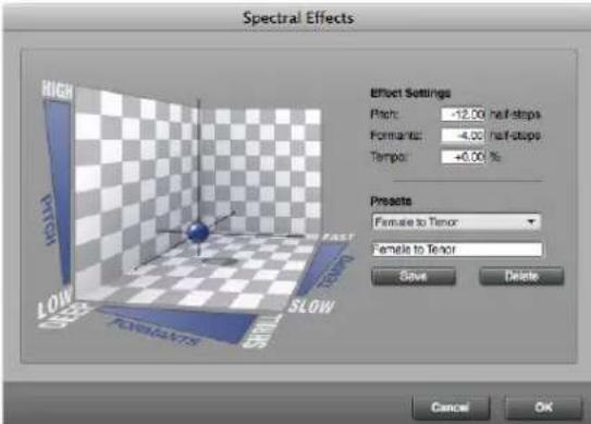
Figure 80-1: The Spectral Effects dialog (in the Audio menu) lets you transpose, time-scale, and gender-bend audio all in one operation. Just drag the globe to the desired position within the space, or type in values as desired. You can save favorite settings for future recall.
WHAT IS A FORMANT?
When you speak (or sing), there are two factors that combine to give your voice its sound. Your vocal cords vibrate at some frequency, and this determines the pitch of the sound. If your vocal cords could somehow vibrate in free space, they would have a buzzy, sawtooth-wave sound to them. The sound contains the fundamental frequency, as well as all of its harmonics, or overtones.
However, your vocal tract (mouth, tongue, and lips) also has a very significant effect on the sound of your voice. Depending on what you are saying, there are different resonant frequencies that are boosted, and other frequencies that are damped. These resonant frequencies are called formants. There are typically three or four formants, which
are constantly changing, depending on whether you are saying “ee,” or “oo,” or “ah,” et cetera. These formants are what determine the vowel or consonant sound that is perceived.
As you can see, the voice is very much like an analog synthesizer. The vocal cords are a sawtooth oscillator, whose output is fed through a series of filters. The words you are speaking determine the resonant frequencies of those filters, i.e., the formants.
WHAT DOES SPECTRAL EFFECTS DO?
The Spectral Effects command lets you change the pitch of a sound and its formants independently. Changing the pitch and the formants by the same amount is identical to Standard pitch shifting. Changing just the pitch is identical to formant-corrected pitch-shifting. Changing both by different amounts produces results that are, to say the least, even more interesting.
GENDER-BENDING
For example, if you leave pitch and tempo alone, and only change the formants by a half-step or two, you can make a soprano sound more like an alto, or make an adult have a more child-like voice. More dramatically, lower the pitch by an octave and the formants by a third or a fourth, and a female voice sounds remarkably like a male voice. This can be a very useful effect for creating a chorus of different sounding voices.
SPECIAL EFFECTS SUCH AS "CHIPMUNKING"
The Spectral Effects command also allows you to get more carried away. If you shift the formants up an octave without changing the pitch or the tempo, you get the famous “chipmunk” effect, without having to sing an octave lower! Obviously this isn’t something you want to do all the time, but it’s there if you need it.
ANY PITCHED AUDIO CAN BE USED
Spectral shifting works best on pitched sounds. (Note that the spoken voice falls within this category.) Our explanation this far has dealt with voice only, but the concept carries through to other sounds. Many sounds are formed by applying resonances to a pitched source. For example, the strings and fretting of a guitar determine the pitch, but the shape of the body gives it its resonances. You can use Spectral Effects to change the tone of a guitar recording without transposing it.
SPECTRAL EFFECTS DIALOG CONTROLS
As shown in Figure 80-1 on page 931, the Spectral Effects window has a 3-D controller that lets you see at one glance the effect you are applying to all three parameters: pitch, formants, and tempo. The position of the ball within the space provided shows the current setting. You can drag it up and down to change the pitch, left and right to change formants (left is lower), and front and back to change the tempo (front is slower). There are also boxes showing the current settings, and you may type in new values (or drag vertically in the text box to change them).
SPECTRAL EFFECTS PRESETS
The controls are useful for fine-tuning an effect, or trying something brand new, but in general you will probably want to use the presets. The preset menu has a number of built-in “factory” presets, with fairly descriptive names. Just choose one from the menu, and it will set the controls. You will probably want to try out some of these presets first to get a feeling for how the controls work.
If you come up with a new setting you'd like to use again, you may save it as a new preset. Just type in a name for it, and hit Save. If you want to delete a preset, select it from the menu, and then hit Delete. Presets are saved in your Preferences file.
APPLYING SPECTRAL EFFECTS TO AUDIO
Like Transpose and Scale Time, the Spectral Effects command works with all the different ways of selecting audio as summarized in “Selecting audio for processing” on page 921. Unlike these other commands, however, Spectral Effects is an Audio-only command; it has no effect on selected MIDI data. Also, unlike the other commands, it is not affected by the settings of the DSP preferences in the Soundbites window. Spectral Effects always processes all selected soundbites.
CHAPTER 81 Transposing Audio
OVERVIEW
Pitch Shifting mode .....935
Pitch automation....936
Using the Transpose command....943
Transposing audio and MIDI together .....944
Temporarily disabling pitch modifications....944
Converting audio pitch to MIDI data....944
Formant-corrected vs. standard pitch shifting .....945
ZTX processing preferences....945
Background processing....946
PITCH SHIFTING MODE
When transposing audio in Digital Performer, there are four possible modes to choose from:
■ ZTX Formant-Corrected
■ ZTX Standard
■ PureDSP Solo Vocal
■ No Pitch Shift
The Pitch shifting mode is chosen in a menu on the soundbite title bar (Figure 81-1) or in the Sound File Information pane (Figure 37-23 on page 366). Each soundbite can be assigned its own mode. You can also access this menu by right-clicking on the soundbite. To assign multiple soundbites to the same setting at one time, select them and then do one of the following:
■ press option/alt while accessing the pitch-shift mode menu (Figure 81-1) on one of the selected bites, or
■ press option/alt while right-clicking one of the selected bites (in any edit layer).
Alternately, select them in the Soundbite list or Sequence Editor and change their setting in the Sound File Info pane (Figure 37-23 on page 366).

Figure 81-1: Choosing the pitch-shifting mode for a soundbite.
ZTX Formant-Corrected
Formant-corrected pitch shifting preserves the original character of the sound by separately transposing the pitch and formants (resonant frequencies) by different amounts. This type of pitch shifting avoids the classic “sampler” effect. For example, vocals transposed up will not get the “chipmunk” effect or, when transposed down, the “Darth Vader” effect. Instead, the quality remains the same and just sounds higher or lower. The advantage of formant-corrected shifting is that results are more true to the original audio’s tone or timbre.
ZTX formant-corrected pitch shifting works well on just about any material, including polyphonic material, such as keyboard tracks, and even full mixes.
ZTX Standard
Standard pitch-shifting transposes pitch and formants by the same amount, producing the classic “sampler” effect described above. It can be applied as desired to any audio material.
PureDSP Solo Vocal
Digital Performer's PureDSP Solo Vocal formant-corrected pitch shifting (carried forward from earlier versions of Digital Performer) often works exceptionally well on solo vocal material. If you are transposing or pitch-correcting solo vocals, try this mode (instead of ZTX Formant-Corrected) to see if it produces the best results.
Pure DSP Solo Vocal does not work on polyphonic material. Use one of the ZTX modes instead for polyphonic material.
When tuning monophonic audio, you may find that PureDSP Solo Vocal often works better than ZTX, especially when fine-tuning vocals.
No Pitch Shift
Us the No Pitch Shift setting for any audio that you would never want to pitch-shift. For example, you would likely not want to transpose audio in dialog tracks, sound effects tracks or percussion tracks. This setting ensures that you won't accidentally transpose the audio (when making multi-track time range selections, for example).
ZTX quality setting
For information about the ZTX quality setting (Figure 81-1 on page 935), see “ZTX Preferences” on page 924 and “ZTX quality setting” on page 936.
PITCH AUTOMATION
Digital Performer allows you to manipulate the pitch of audio material in the form of pitch automation data that can be edited directly in the track where the audio resides. Like volume and pan, pitch automation is applied non-destructively to track output in real-time during playback. A wide variety of pitch-related operations can be performed on audio data, from simple pitch correction using the Pencil tool, to individual note transposition, to wholesale transposing of an entire track from one mode or key to another using the Transpose command. The success of these operations depends highly on the nature of the audio material itself.
Pitch automation can be applied to mono, stereo and even surround audio files, and it can be applied to any pitched audio material, including the spoken human voice.
Pitch analysis
Pitch automation is based on ZTX processing (page 921). Therefore, if you plan to use pitch automation and you've disabled preemptive file analysis, you will find it more convenient to re-enable background file analysis. To do so, choose Preferences from the Digital Performer menu (macOS) or Edit menu (Windows) and click the Background Processing item in the list. See "Background processing preferences" on page 928.
Latency compensation
Pitch automation requires Digital Performer's latency compensation features, so be sure that the Automatic Plug-in Latency Compensation option is enabled in the Setup menu> Configure Audio System> Configure Studio Settings dialog. See "Automatic plug-in latency (delay) compensation" on page 34 in the DP4 Getting Started Guide.
Pitch automation note range
Pitch automation edits are limited to the note range C0 through C6.
Pitch edits are bound to soundbites
Even though they look just like volume, pan and other track-based automation data types, pitch automation edits are bound to the specific soundbite on which you perform the edit. This
means that if you then move the soundbite, the pitch edits move with it. In addition, all instances of the soundbite in the project are affected. Conversely, you can create harmonies from the same source audio by creating different soundbites from the same parent audio file region. Each separate soundbite can have unique pitch edits.
Pitch adjustments are non-destructive
Any adjustments that you make to the pitch of audio are non-destructive and non-constructive. In other words, the original audio data is not modified in any way, nor is any new audio data generated on disk. Instead, pitch modifications are rendered in real-time by Digital Performer's processing engine. Therefore, they can be quickly applied, modified and removed, even during playback. In fact, you might find it most useful to keep playback going — and even loop sections — when you are editing pitch, as you will enjoy the benefit of instant feedback as you work. Pitch adjustments can, however, be permanently applied to audio by merging the soundbite or (unlike other forms of automation) exporting the soundbite.
Viewing pitch automation
To access pitch automation, choose Pitch from the Sequence Editor track layer menu (Figure 81-2). You can also view pitch automation in the Waveform Editor by clicking the Pitch tab as explained in "Edit Layers" on page 531. This chapter uses the Sequence Editor for its examples, but pitch automation in the Waveform Editor works similarly to the way it works in the Sequence Editor.
The pitch layer represents the pitch of the audio in two forms, superimposed on top of the waveform: 1) as a blue line (the pitch curve) and 2) as bars or pitch segments. Both are measured by the pitch ruler along the left edge of the track. You can expand the vertical size of the track, zoom the vertical resolution and scroll the vertical position of the pitch layer information, all independently of

Figure 81-2: Pitch automation.
the waveform display. This allows you, for example, to position the pitch information above or below the actual waveform, rather than directly on top of it.
Absolute vs. relative pitch editing
There are two modes for editing pitch: Absolute and Relative, chosen from the Pitch layer mode menu (Figure 81-2). These two modes do not change how the audio plays back, just how it is viewed and edited.
Absolute
Absolute mode displays pitches as directly editable bars in a piano roll style edit layer with a vertical, multi-octave pitch ruler along left edge of the track lane (as shown in Figure 81-2). This mode is best for tuning monophonic audio (i.e. solo vocals, solo instruments, etc.)
Relative
Editing in Relative mode simply allows pitch to be offset by some amount. The pitch ruler keyboard shows interval offsets, mirrored above and below a center (root) line, rather than absolute pitches from top to bottom (Figure 81-3). The root pitch in the pitch ruler is indicated by the track color.

Figure 81-3: Relative pitch editing mode.
Initially, Relative mode displays a single bar for the entire soundbite (Figure 81-3), which you can drag up and down. Use the scissor tool to split the bar into segments, which can then be individually
dragged up or down (Figure 81-4), similar to Absolute mode. The scissor tool responds to grid snapping, if enabled. When dragged vertically, pitch bars snap to the chromatic scale in the pitch ruler. For fine-tuned adjustments, hold down command/ctrl to override pitch snapping while dragging vertically.

Figure 81-4: Use the scissor tool to create and drag pitch segments.
Relative mode can be used for monophonic material, but it also works well for full mixes and polyphonic audio, which cannot be represented with single pitch bars.
The pitch curve
The blue pitch curve (Figure 81-2) represents the original pitch. If you modify the pitch curve in any way, the modified portions of the curve are
displayed in red. You can select and edit the pitch curve directly using the Arrow tool and the Pencil tool, as follows:
To do this to the pitch curve Do this
| To redraw the pitch curve Set the Pencil/Reshape curve menu in the Tool palette to Free and drag over the pitch curve with the Pencil tool. | |
| To select the pitch curve Drag over it with the Arrow tool (lasso cursor), or click a pitch segment to select the part of the curve that it represents. | |
| To get rid of any red portions (modifications) | Select the curve and hit delete, or choose Audio menu> Pitch and Stretch > Clear Pitch. |
| To scale the existing curve Option/Alt-click the curve and then drag vertically. See “Scaling the pitch curve” below for further details. | |
| To reshape the curve Choose the desired shape from the Pencil/Reshape curve menu in the Tool palette, set the edit grid resolution (if desired) and drag over the pitch curve with the Pencil tool. | |
Pitch curve control points
Control points can be added to the pitch curve to modify it as follows:
To do this Do this
| To add a control point Double-click the pitch curve with the Arrow tool. | |
| To modify the pitch curve with the control point | Drag the control point with the Arrow tool. |
| To anchor the pitch curve on either side of a control point when you drag it | Add control points on either side of it at the locations where you want to anchor the curve. |
| To select a control point Drag over it with the Arrow tool (lasso cursor). | |
To delete a control point Select the portion of the pitch curve and choose Audio menu> Pitch and Stretch > Clear Pitch Control Points.

flowchart
graph TD
A["Top Node"] --> B["Blue Node"]
B --> C["Red Line"]
C --> D["Bottom Node"]
D --> E["Blue Node"]
E --> F["Red Line"]
F --> G["Bottom Node"]
style A fill:#f9f,stroke:#333
style B fill:#bbf,stroke:#333
style C fill:#bfb,stroke:#333
style D fill:#ffb,stroke:#333
style E fill:#ffb,stroke:#333
style F fill:#ffb,stroke:#333
Figure 81-5: Pitch curve control points.
For best results
Although you can make precise pitch adjustments on the pitch curve with the Pencil tool and control points, often you will achieve more natural results by simply transposing and scaling the original curve as described in the following sections.
Scaling the pitch curve
Option/Alt-drag vertically on the pitch curve to scale it. Dragging upwards accentuates the existing curve; dragging down flattens it. The portion of the curve that is affected by the scaling operation is determined by:
■ the end points of the pitch segment at the location where you click, or
■ the currently selected portion of the pitch curve, if any.
You can also scale the pitch curve by selecting the portion you wish to scale and choosing Audio menu> Pitch and Stretch > Scale Expression.
Scaling the pitch curve can be used for a variety of applications. Here are a few examples:
■ To produce more or less vibrato in audio that already has some vibrato
■ To reduce unwanted variations in pitch
■ To enhance variations in pitch
Original Scaled up scaled down

natural_image
Three-panel illustration showing waveform patterns with blue and red oscillations (no text or symbols)Figure 81-6: Option/Alt-drag vertically to scale the existing pitch curve. In this example, vibrato is being reduced and increased.
Editing the pitch curve in relative mode
You can edit the pitch curve in both absolute and relative modes. If you don't see the pitch curve, try zooming in horizontally. Keep in mind that
Absolute and Relative modes are different views of the same pitch curve. If edits are made in Absolute mode, Relative mode's pitch bar(s) will move accordingly (and vice versa).

Figure 81-7: Editing the pitch curve in Relative mode.
Pitch segments
In Absolute mode, Pitch segments (Figure 81-2) represent the detected average root pitch of each note in the audio. In Relative mode (Figure 81-4), they represent deviations from the original pitch. They are displayed in the color assigned to the track. These segments can be fine-tuned in a variety of ways to accurately represent individual notes in the audio — without changing the audio itself. You can then use the pitch segments to modify the pitch of the audio in a wide variety of ways, from micro-tonal tuning adjustments to wholesale transposition and key changes. You can even copy and paste pitch segments into a MIDI track to create MIDI notes that match the source audio.
Fine-tuning pitch segments
In Absolute mode, pitch segments are most useful when they accurately represent the pitch and duration of each individual note in the audio. Digital Performer does its best to detect the root pitch, beginning and end of each note. But further adjustment may be necessary. For example, a singer may bend the pitch of a held note, causing DP to represent the audio as two different pitch segments. To accurately represent them as one continuous segment, you can go in by hand to merge them together into a single pitch segment. As another example, you might want to slightly adjust where the transition from one segment to another occurs.
Fine-tuning pitch segments does not affect audio. It is crucial to understand that the types of changes to the pitch segments being discussed so far have no effect whatsoever on the audio signal itself. Instead, the purpose of these changes is to represent as accurately as possible the notes in the original audio signal itself. The more accurate the pitch segment representation, the more successfully you will be able to modify the pitch of the audio using the pitch segments (via several techniques discussed later).
Setting the pitch mode
Before you make individual adjustments to pitch segments, you should first choose an overall pitch mode for the audio. There are two different pitch modes: vocals and instruments. Choosing the appropriate pitch mode for the audio material you are working with can dramatically improve the initial representation of the pitch segments, so that you'll have much less tweaking to do by hand, if any. To set the pitch mode for a track or soundbite, select it (in either the Sequence Editor or the Waveform Editor) and then choose Audio menu> Pitch and Stretch, and then choose the desired sub-menu command:
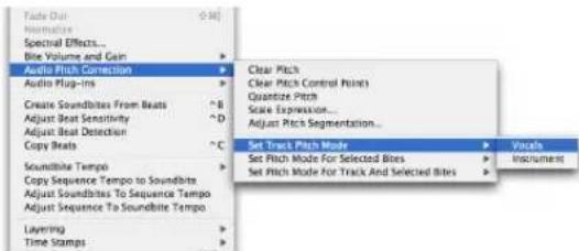
Figure 81-8: Setting the pitch mode for a soundbite or track.
Here is a summary of how these three pitch mode commands affect pitch segments:
Pitch mode command What it does
| Set Track Pitch Mode Sets the default pitch mode for any audio material newly recorded into that track. It does NOT affect existing soundbites already in the track, or soundbites dragged into the track. | |
| Set Pitch Mode for Selected Bites | Sets the pitch mode and modifies the pitch segments accordingly for the currently selected audio in the Soundbites window or in any tracks. |
Set Pitch Mode for Track Applies the pitch mode to both the track and Selected Bites and any currently selected soundbites as described above in one operation.
Adjusting pitch segmentation
Another way to control overall pitch segmentation accuracy is to select the desired audio and then choose Audio menu> Pitch and Stretch >Adjust Pitch Segmentation:

Figure 81-9: Adjust Pitch Segmentation.
Move the slider to the right for more detailed segmentation; move it left for less detail. The Instruments and Vocals settings along the slider match their corresponding menu settings shown in Figure 81-8 on page 940 and produce the same results and the respective menu setting.

Figure 81-10: Adjusting pitch segmentation.
Adjusting pitch segments while playing back It can help to loop a section and make pitch segment adjustments during playback to match what you are seeing with what you are hearing. This goes for all pitch segment editing.
Editing pitch segments
After you've chosen the pitch mode for the track or soundbite, you can further modify the pitch segments to more accurately reflect the notes in the audio as follows:
To do this Do this Example
| To joinadjacentsegments | Click between themwith the Mute tool.[8200] | Before |  |
| After | 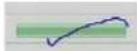 | ||
| To splitadjacentsegments | Click with theScissor tool.[3062] | Before | 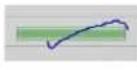 |
| After | 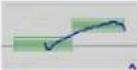 | ||
| To move theboundary betweentwo segments | Drag one of theadjacent segmentedges with the Arrowtool (using the trimcursor shown below) ↔ ↔ | Before |  |
| After |  |
Trimming pitch segments
As noted above, you can position the Arrow tool over the edge of a pitch segment to get the trim cursor (shown in the table). Drag horizontally with the trim cursor to move the edge of the segment. If the pitch segment you are trimming lies adjacent to silence (at the beginning or end of the audio signal), you are not allowed to extend the segment into the silence, as segments only represent portions of the soundbite that have audio signal of some kind.
line
| Time | Value | |------|-------| | 0 | 0.5 | | 1 | 0.6 | | 2 | 0.4 | | 3 | 0.7 | | 4 | 0.8 | | 5 | 0.6 | | 6 | 0.9 | | 7 | 0.7 | | 8 | 0.8 | | 9 | 0.6 | | 10 | 0.9 | | 11 | 0.7 | | 12 | 0.8 | | 13 | 0.6 | | 14 | 0.9 | | 15 | 0.8 | | 16 | 0.7 | | 17 | 0.8 | | 18 | 0.6 | | 19 | 0.9 | | 20 | 0.8 | | 21 | 0.7 | | 22 | 0.8 | | 23 | 0.6 | | 24 | 0.9 | | 25 | 0.8 | | 26 | 0.7 | | 27 | 0.8 | | 28 | 0.6 | | 29 | 0.9 | | 30 | 0.8 | | 31 | 0.7 | | 32 | 0.8 | | 33 | 0.6 | | 34 | 0.9 | | 35 | 0.8 | | 36 | 0.7 | | 37 | 0.8 | | 38 | 0.6 | | 39 | 0.9 | | 40 | 0.8 | | 41 | 0.7 | | 42 | 0.8 | | 43 | 0.6 | | 44 | 0.9 | | 45 | 0.8 | | 46 | 0.7 | | 47 | 0.8 | | 48 | 0.6 | | 49 | 0.9 | | 50 | 0.8 | | 51 | 0.7 | | 52 | 0.8 | | 53 | 0.6 | | 54 | 0.9 | | 55 | 0.8 | | 56 | 0.7 | | 57 | 0.8 | | 58 | 0.6 | | 59 | 0.9 | | 60 | 0.8 | | 61 | 0.7 | | 62 | 0.8 | | 63 | 0.6 | | 64 | 0.9 | | 65 | 0.8 | | 66 | 0.7 | | 67 | 0.8 | | 68 | 0.6 | | 69 | 0.9 | | 70 | 0.8 | | 71 | 0.7 | | 72 | 0.8 | | 73 | 0.6 | | 74 | 0.9 | | 75 | 0.8 | | 76 | 0.7 | | 77 | 0.8 | | 78 | 0.6 | | 79 | 0.9 | | 80 | 0.8 | | 81 | 0.7 | | 82 | 0.8 | | 83 | 0.6 | | 84 | 0.9 | | 85 | 0.8 | | 86 | 0.7 | | 87 | 0.8 | | 88 | 0.6 | | 89 | 0.9 | | 90 | 0.8 | | 91 | 0.7 | | 92 | 0.8 | | 93 | 0.6 | | 94 | 0.9 | | 95 | 0.8 | | 96 | 0.7 | | 97 | 0.8 | | 98 | 0.6 | | 99 | 0.9 | | Note: The actual values may vary due to the random nature of the data generation process. The provided values are just an example from the code execution.Figure 81-11: The right edge of this pitch segment cannot be dragged to the right because there is silence there.
Gray pitch segments
Gray pitch segments represent portions of the audio signal that have no detectable pitch. For example, a percussive drum sound, such as a cymbal, has no clearly defined root pitch. Another example are the sibilants found in vocal tracks: these are sounds such as “s” or “ch” that do not have pitch to them.

Figure 81-12: Gray (unpitched) segments.
Gray segments are displayed to indicate that there is signal present in the audio, but that the signal has no detectable pitch. Gray segments cannot be modified (since there is no pitch information to transpose).
Dangling segments
A dangling segment is a portion of a segment for which there is no pitch curve. This is most often the result of unpitched material that is not yet split into its own gray segment. In the example below, the dangling segment on the left has been split into a gray segment using the Scissor and Trim tools. There may be situations, however, where dangling segments are preferred, such as when you convert pitch segments into MIDI notes (“Converting audio pitch to MIDI data” on page 944).
natural_image
Abstract blue and purple graphic with no visible text or symbols
Figure 81-13: A dangling segment that has been converted to an unpitched gray segment via segment editing.
Reverting to the default pitch segmentation
If you edit the pitch segments and then decide you want to start over, select the soundbite and choose Audio menu> Pitch and Stretch > Set Pitch Mode for Selected Bites> and then choose either vocals or instruments. Doing so recomputes the pitch segments and restores them to their original state, before any modifications.
Modifying pitch using pitch segments
After the pitch segments accurately reflect the notes in the audio, as explained in the previous sections, you can use the pitch segments to transpose the audio as follows:
To do this Do this
| To transpose a note chromatically | Drag its pitch segment vertically. The note snaps to the root pitches in the pitch ruler, but also maintains its relative position to the root pitch (if its a little sharp or flat). |
| To correct the pitch slightly or perform other micro-tonal adjustments | Command/Ctrl-drag the pitch segment vertically. |
| To select the pitch segment (and Click the pitch segment with the the portion of the pitch curve that Arrow (finger) tool. it represents) | |
| To select multiple pitch segments Shift-click them or drag over them with the Arrow (lasso) tool. | |
| To drag multiple pitch segments Select them first and then drag them. | |
| To return a pitch segment to its original pitch | Select it and hit delete, or choose Audio menu> Pitch and Stretch > Clear Pitch. |
When you modify pitch segments, the pitch curve reflects those changes. In fact, the pitch segments are essentially “note-bound” handles for the pitch curve itself, so when you edit the segments, you are really editing the pitch curve. The segments merely provide a musical way to manipulate the curve, including smooth pitch transitions between notes when transposing individual notes.

Figure 81-14: Editing pitch by dragging a pitch segment.
Quantizing pitch
If you would like to “center” one or more pitch segments, so that they are tuned exactly to their relative root pitch (to fix any notes that are a little sharp or flat), select their pitch segments and choose Audio menu> Pitch and Stretch > Quantize Pitch. Doing so centers each pitch segment with its corresponding root pitch (or relative interval) in the pitch ruler. In general, you achieve best results from this operation if you first edit pitch segments with the Mute and Scissor tools, as explained in “Editing pitch segments” on page 941.
Setting the pitch reference
By default, pitch editing is based on the standard "A 440" tuning reference, where the A above middle C is 440 Hz. However, you can adjust this tuning reference as desired in the Data Display preferences (Figure 7-9 on page 81). See "Audio pitch automation reference" on page 82.
USING THE TRANSPOSE COMMAND
You can use Digital Performer's standard Transpose command (Region menu) to apply a wide variety of transpose operations on the pitch segments and the audio data they represent. Select the pitch segments you wish to transpose (using any of the techniques discussed in the previous section) — or just select the audio itself — and choose Region menu>Transpose. Make sure the Transpose audio check box is checked, and the Transpose audio by adjusting pitch automation option is chosen, as demonstrated in Figure 81-15 below:

Figure 81-15: Check the 'Transpose audio' check box to transpose audio data.
You can then choose any form of transposition option you wish, including Interval, Diatonic, Key/Scale and even Custom Map. This is a very powerful feature because it gives you the same level of complete control when transposing audio as you do when transposing MIDI data. Keep in mind, however, that the success of audio transposition operations like this, as with all pitch-shifting, depends on the size of the intervals involved and the nature of the audio material being transposed. Some types of audio material transpose better than others.
Another important factor for successful transposition is the accuracy with which the pitch segments in the pitch layer of the track represent the actual notes in the audio, as explained in the
previous sections. So before using the Transpose command to transpose audio, it is a good idea to spend some time reviewing the pitch segments for accuracy.
In the example above (Figure 81-15), audio is being transposed from one key and mode (C minor) to an entirely different key and mode (D Phrygian).
TRANSPOSING AUDIO AND MIDI TOGETHER
When using the Transpose command (Figure 81-15), you can of course select both audio and MIDI tracks together to transpose them in one operation. Just be sure to check both the MIDI and audio check boxes as shown in Figure 81-15.
TEMPORARILY DISABLING PITCH MODIFICATIONS
Any modifications you make to the pitch of audio in the Pitch Layer of an audio track can be temporarily disabled using the techniques described below. When you disable pitch modification in this way, all pitch edits are fully preserved, and you can re-enable them at any time:
To do this Do this
To temporarily disable all pitch modifications in the entire track
Click the 'P' button at the bottom of the track's pitch ruler in the Sequence Editor. You can also use DP's Option/Alt-click and Command/Ctrl-click shortcuts. Or choose Pitch from the track settings menu.
To temporarily disable a specific In the Sound File Info window, set soundbite's pitch modifications the soundbite's Transpose attribute to Don't Pitch Shift.
When pitch edits are disabled, you cannot edit the track pitch layer information.
When pitch automation is bypassed using the 'P' button, the data is still processed in real-time so that you can immediately hear the results when you unbypass. In this case, the bypassed pitch automation takes up just as much computer processing resources as when it is unbypassed (playing).
When pitch automation is bypassed via the Don't Pitch Shift soundbite setting, the pitch data is completely ignored, therefore conserving your computer's processing resources.
CONVERTING AUDIO PITCH TO MIDI DATA
Pitch segments (Figure 81-2) can be copied and pasted into MIDI tracks, essentially allowing you to convert the pitch information in the audio into MIDI data. This powerful feature can be used for a wide variety of applications. For example, you could layer a vocal part with MIDI parts, or sing a melody and then convert it to MIDI data for further development. The possibilities are endless.
The accuracy of the MIDI transcription is entirely dependent on the accuracy with which the pitch segments represent the notes in the audio. The more accurately the pitch segments represent the actual audio, the more accurate the MIDI transcription.
Preparing for MIDI pitch transcription
Pitch segments are copied and pasted as is, so if you have made any modifications to the pitch segments — or changes to the pitch curve that are reflected by the pitch segments — the changes will be carried over into the MIDI track.
For best results, try these preparations on the pitch segments before you copy and paste them:
- Quantize pitch (Audio menu> Pitch and Stretch > Quantize Pitch) to ensure that each note is centered on its root pitch.
■ Make sure there is a one-to-one correspondence between each pitch segment and each note that you hear in the audio.
■ Review the timing of the pitch segments — where they start and end — to accurately reflect the full duration of each note.
These preparations will help a lot, but it is important that you realize that the resulting MIDI notes will not match the pitch segments exactly. See "What you see is not what you'll necessarily get" below.
Copying and pasting pitch segments
After making the preparations listed above, copy and paste pitch segments as follows. This procedure assumes that you want the resulting MIDI notes to play in time with the original audio, so you will be pasting the MIDI data at the location where the first pitch segment begins:
1 Select the pitch segments with the Arrow tool (lasso cursor).
2 Choose Copy from the Edit menu.
3 To paste the resulting MIDI notes so that they play in time with the original audio, leave the pitch segments selected and choose Set to Selection Bounds from the Selection Information window's Set To menu as shown below in Figure 81-16.
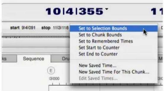
Figure 81-16: Setting the selection to match the currently selected pitch segments.
4 Click the name of the MIDI track you wish to paste into to create a time range selection in the destination track that matches the current selection start time (which now matches the start time of the first pitch segment you copied).
5 Choose Paste from the Edit menu.
What you see is not what you'll necessarily get
When you copy pitch segments and paste them into a MIDI track, the resulting MIDI notes will likely not exactly match the original pitch segments. This is because Digital Performer interprets the pitch segments with respect to the waveform to create a MIDI performance that matches the audio as closely as possible.
To further refine the timing of the resulting MIDI notes, try quantizing them. Best results are often achieved by quantizing both attacks and releases of the MIDI notes.
FORMANT-CORRECTED VS. STANDARD PITCH SHIFTING
In the Sound File Information window (Figure 37-22 on page 365), each soundbite can be configured for either formant-corrected pitch shifting or standard pitch shifting (Figure 37-23 on page 366). This setting affects real-time pitch automation. If you wish to preserve the original character of the sound, such as for harmonizing or pitch correction, use the (default) formant-corrected setting. For special pitch effects, experiment with standard pitch shifting. For further information about these modes, see "Soundbite preferences for transposing and time-stretching" on page 365.
ZTX PROCESSING PREFERENCES
In Preferences > Audio Options (Figure 7-28 on page 94), the Pitch and Time Stretch Options let you adjust the quality and speed of the ZTX
processing. Try experimenting with different settings here for best results. You can change the settings on the fly at any time.
BACKGROUND PROCESSING
As soon as you OK the Transpose dialog, the selected soundbites (or pieces of soundbites, for a time-ruler selection) are replaced with new soundbites, which are analyzed and processed in the background as described in “Background Processing” on page 923.
CHAPTER 82 Scale Time
TIME SCALING
Time scaling means you can change the length of recorded digital audio without changing the frequency. As with pitch-shifting, there are limits as to how far you can shift and still have a musically useful result. The limits are not hard and fast, however. They depend on the audio, and on the intended use (e.g., soloed versus buried in a mix). Some audio sounds fine after its tempo has been halved or doubled, but most will start sounding a little unusual before such an extreme compression or expansion is reached.
THE SCALE TIME COMMAND
The Scale Time command (in the Region menu) now allows you to compress or expand soundbites. It also has an improved, more flexible interface.

Figure 82-1: The Scale Time command supports MIDI data, audio data, and both at the same time. Two examples are pictured: scaling by SMPTE frame times and by measures, beats, and ticks. Note that you can also enter the amount as a percentage, or as a ratio (by clicking the scale factor button).
The Scale Time dialog shows the current start and end times and duration of the selection. Below that are values for the new start and end times and duration. A button to the right lets you choose whether to display these times as measures, real time, or SMPTE time. If you know the new duration or end time, you can just type in either field and hit OK. If you'd rather enter the scale factor as a ratio or a percentage, you may do that as well, as shown in Figure 82-1.
The Scale Audio checkbox determines whether selected soundbites (or pieces of soundbites) should be time-scaled. If it is not checked, only the start times are changed. When scaling audio, you may not expand by a factor of more than 10 to 1, or compress by more than 1 to 10. (This is not much of a practical limitation — very few soundbites will sound good when stretched by a factor of 2, let alone 10.) If the Scale Audio checkbox is not checked, you may scale by up to a factor of 100.
SELECTING A REGION TO TIME SCALE
As with Transpose, the Scale Time command works with any of the methods of selection discussed in “Selecting audio for processing” on page 921, and it allows you to scale audio and MIDI data together. It can also be used to change the duration of a single soundbite, selected in the Event List, Sequence Editor, or Soundbites window.
THE "DON'T TIME SCALE" PREFERENCE
The Scale Time command checks each selected soundbite's Time Compress/Expand preference (as shown on page 365) to determine what to do. Only soundbites set to Allow Time Scale will be time-scaled. Soundbites set to Don't Time Scale will only have their start time changed.
AUDIO AND TEMPO
See chapter 52, "Tempos and Audio" (page 673).
GRAPHICALLY TIME-SCALING AUDIO
See "Graphic time stretching of audio" on
page 396.
CHAPTER 83 VocAlign
OVERVIEW
VocALign is an audio alignment tool from SynchroArts (http://www.synchroarts.co.uk) which will automatically synchronize two audio signals at the touch of a button. You can control most VocAlign functions from Digital Performer while VocAlign runs in the background.
VocAlign works by automatically “micro-editing” the new or replacement audio signal to align the timing of its modulations to match a guide signal. This can be useful for lip-syncing, foreign dialogue replacement, tightening-up of double-tracking, backing vocals and instruments and modifying the timing of one music track to match another.
HOW IT WORKS
1 Be sure VocAlign is running in the background.
2 In Digital Performer, select a soundbite that will serve as the guide file for the audio you wish to align.
3 Under the Audio menu, select Set Guide File from the VocAlign sub-menu:

4 Select the soundbite you wish to align to the guide file.
5 Under the audio menu, select VocAlign > Set Dub File. VocAlign first analyzes the two signals' time-varying energy through filter banks.

Figure 83-1: VocAlign from SynchroArts.
6 Under the audio menu, select VocAlign > Align and spot audio.
Using the guide and dub energy patterns, VocAlign automatically generates a best-fit alignment path, and “micro-edits” the waveform of the dub or replacement audio so it’s energy modulations matches those of the original signal. When VocAlign is finished, it will replace the dub file with the newly aligned audio in exactly the same place in Digital Performer.
If you plan to use VocAlign extensively on your project, you may want to consider adding keyboard shortcuts with the Commands window (see chapter 9, "Commands" (page 105)). If you would like more information concerning the deeper operations of VocAlign, consult the VocAlign manual.

Figure 83-2: The VocAlign commands.
Set Dub, Align and Spot Audio
The Set Dub, Align and Spot Audio command allows you to quickly align dub files to the current guide file in a very simple two-step process:
SET GUIDE FILE
SET DUB, ALIGN AND SPOT AUDIO
The Set Dub, Align and Spot Audio command also allows you to quickly align multiple dub files to the current guide file with one easy keyboard shortcut per dub file. According to Synchro Arts, the company that developed VocAlign, this is the tightest integration currently available for VocAlign in any host workstation product on the
market. This new command, as well as all of the VocAlign sub-menu commands, work with both VocAlign Pro and VocAlign Project.
Part 9
Mastering
CHAPTER 84 Bounce To Disk
OVERVIEW
Bounce to Disk lets you mix down an output (or outputs) to an audio file (or set of audio files). Original tracks are preserved and new audio files are created. A bounce operation can be done offline (faster than real-time) or in real-time (so you can listen to audio playback of your mix during the bounce process).
Bouncing is commonly used for creating a final mix of a project for mastering and delivery. Bouncing can also be used:
■ to create a single, contiguous audio file out of a track composed of many smaller ones
■ to temporarily bounce down multiple tracks to conserve CPU resources
■ to export a project as multiple “stems” (separate audio files) for import into other audio apps
Since bouncing occurs in the digital realm, no noise or sonic degradation is introduced. You can bounce as many times as you like without introducing any artifacts as a result of bouncing.
When bouncing, you can choose to create a single resulting audio file or multiple separate files (stems) generated from multiple tracks or audio outputs in your system.
You can also use the Bounce to Disk feature to burn a CD, create a disk image or to export a movie with your Digital Performer sound track.
Previewing....953
Bouncing to Disk....953
Bounce to Disk settings 954
Bouncing to MP3....960
Bouncing to a CD or disk image (Mac only) ..... 961
Bouncing to a Movie 966
Bouncing stems 967
The Bounce Settings menu 967
PREVIEWING
When bouncing, what you hear on each output when you play back the sequence is what you will get in the resulting mixdown of that output. To preview the results of the bounce, solo the tracks you wish to include in the bounce and play back the sequence.
BOUNCING TO DISK
Bouncing to disk is a simple three step process:
1 Select any portion of one or more audio tracks.
2 Choose Bounce to Disk from the File menu.
3 Adjust the settings in the Bounce to Disk dialog as desired (Figure 84-1 on page 953) and click OK.
You'll then see the progress window shown below.

Figure 84-1: The progress window for the Bounce command.
The resulting audio file will sound exactly the same as the output of the track(s) you selected, including volume/pan automation, mute/solo settings, real time MAS, VST and AU effects, EQ
and any other real time processing that is applied to the selected output. Here is a summary of what is included:
Audible tracks
All audible tracks that are routed to the output which is selected as the source of the bounce are included in the bounce. Muted tracks are not included. If you solo one or more tracks, only the soloed tracks are included in the bounced mix.
Automation
All enabled automation is played back and incorporated in the bounced mix.
Inserts and sends
All active inserts, including real-time plug-ins and hardware inserts, are applied to the bounced mix.
Selection length
The bounced mix will be the length of the selection you made before initiating Bounce to Disk.
Time stamps
Bounced material is automatically time stamped so that you can drag it into a track and place it at the same location as the original material. For more information about time stamping, see “Timestamps” on page 651.
Delay compensation
Bounce to Disk compensates for any bus and plug-in delays. If a bounced file is imported back into a session and aligned with the source mix, it will be correctly aligned with the original source mix.
BOUNCE TO DISK SETTINGS
The Bounce to Disk dialog (Figure 84-2) provides the following settings.
File Format
The File Format menu (Figure 84-2) lets you bounce to variety of file formats or destinations (Figure 84-3).
To use the project's current file format and interleaved format, choose Project Format.

Figure 84-2: Digital Performer's Bounce to Disk feature (File menu).
For details about bouncing to an audio CD or audio CD disk image, see “Bouncing to a CD or disk image (Mac only)” on page 961.
The Core Audio file formats, which are supplied by macOS, always create interleaved files.
For details about bouncing to the MP3 format, see "Bouncing to MP3" on page 960.
For details about bouncing to a QuickTime movie (on macOS), see "Bouncing to a Movie" on page 966.

macOS

Windows
Figure 84-3: The Bounce to Disk File Format menu.
Offline Bounce
When Offline Bounce is enabled, processing occurs faster than real time. Therefore, there is no playback during the bounce operation. Factors that affect the speed of offline bouncing include:
- The speed of your computer's CPU — The faster your computer is, the faster the offline bounce.
■ The number of tracks selected — If what you have selected can be played by your computer in real time, then offline bouncing will probably occur faster than real time. If you have selected more tracks than you can play at one time, then the operation may not occur faster than real time.
■ Disk speed — Potentially large amounts of audio data are pulled from your hard drive during offline bouncing. The performance of your storage device can therefore impact offline speed. - Third-party plug-ins — Some third-party plug-ins may slow down offline bounce operations due to their CPU requirements.
If you experience issues with third-party plug-ins during bounce operations, first try doing a real-time bounce (with Offline Bounce disabled). If that doesn't help, use another method to render the track as audio, such as Freeze Tracks (see page 152).
Limitations of Offline Bounce
When using Offline Bounce, the following are not included in the resulting mixdown:
■ Hardware inserts
■ External audio sources monitored by aux tracks
■ Any audio source that is synchronized externally
Real-time bounce (Offline bounce disabled)
When Offline Bounce is turned off, the bounce operation proceeds exactly as if it were playing back in real time. This offers several advantages:
■ You can listen to the results of the bounce as it processes.
- You can include external live inputs in the mixdown, including monitored inputs, aux tracks and virtual instrument hosting environments like Vienna Ensemble Pro, as well as hardware synthesizers. See “Bounce Includes Audio Patch Thru” on page 969.
■ You can include hardware inserts.
Channels
The Channels menu (Figure 84-2) lets you choose the channel format for the bounced material with four choices (Figure 84-4):

Figure 84-4: The Bounce to Disk Channels menu.
Mono (no attenuation)
Mono (Figure 84-4) creates a single monophonic audio file. Digital Performer simply sums the left and right channels of the outputs of the source tracks, so there is a possibility that the resulting mono mix might clip, even when the source material does not. If this is the case, undo the bounce operation, adjust the levels of the source tracks and bounce again.
Mono (with 3.5 dB attenuation)
When bouncing to mono, the with 3.5 dB attenuation option (Figure 84-4) preserves the level when bouncing a signal that is panned center. The attenuation compensates for the 3.5 dB boost you get from summing the left and right channels of a centered signal with equal-power panning.
Stereo
The Stereo option (Figure 84-4) creates a stereo file. If you've chosen a multi-channel bundle as the source, it will be folded down to stereo. If an interleaved format is chosen, Stereo creates an interleaved stereo file. If a deinterleaved format is chosen, Stereo creates two mono audio files with the same file name, but with ".L" or ".R" appended to the end of the file names.
Same as Source
The Same as Source option (Figure 84-4) creates a file with the same channelization as the Source bundle (see “Source” below). The resulting file can be interleaved or deinterleaved, depending on the format chosen.
Match Track Format
The number of channels for a track's output may not match the track's channel format. For example, a mono track might be assigned to a stereo output, so the track output is stereo, even though the track format is mono. When you choose the Match Track Format option (Figure 84-4), the resulting bounce mix is folded down to match the track channel format, such that mono tracks will result in mono files, even if they are assigned to stereo outputs.
Sample Format
The Sample Format menu (Figure 84-2) lets you choose the bit depth for the bounced audio (Figure 84-5):

Figure 84-5: The Bounce to Disk Sample Format menu.
Supported fixed bit depths include 8, 16 or 24 bit integer. You can also choose 32 bit Floating Point, if the format you've chosen (Figure 84-3) supports this resolution. If not, this menu choice is grayed out.
Choose Project Default to use the current project sample format. If you choose 8 bits (a sample format not supported by Digital Performer for playback), the Import option below will force you to choose the Do not import setting.
Supported resolutions
8-bit resolution it typically applied to audio that will be used in multimedia and internet applications because it significantly reduces the size of the audio files, halving the bandwidth required to deliver the sound. When you are bouncing down to 8-bit audio, you may want to apply Digital Performer's MasterWorks Compressor (or a third-party dynamics plug-in of your choice) to the mix to counteract the effect of halving the dynamic range that results from going to 8 bits.
16-bit resolution is the standard resolution for compact disc audio.
24-bit audio provides greater resolution and headroom and is used by many mastering systems.
32-bit floating point audio file resolution is an emerging standard used for high-end recording, mixing and mastering applications. Digital Performer's mix engine employs 32-bit floating point precision throughout, as do other advanced digital audio workstation systems. If you plan to use the bounced material with Digital Performer or another system that supports 32-bit floating point processing, this option is a good way to preserve and carry over the floating point precision employed by these systems.
Import
The Import menu (Figure 84-2) lets you choose what to do with the audio files generated by the bounce operation. If you choose Do not import, the file will be created on the hard drive but it will not be imported into Digital Performer. Otherwise, you can import the audio file into the Soundbites window or into the current sequence as a new audio track. If you have chosen a format not supported by Digital Performer, you will not be allowed to choose either of these import options.
Source
There are two types of sources you can select to capture in a bounce: Tracks and Outputs. Multiple tracks and outputs can be selected, resulting in multiple mixdown files (to export stems, for example). Selecting an output captures the audio from that output in the resulting mixdown file. Selecting a track captures the audio from the track's output.
When more than one source is selected, each resulting mixdown audio file is given a unique name as follows: the base name entered in the File Name field (Figure 84-2 on page 954), plus the name of the track or output appended to the end of the file name.
Source tracks
Disk tracks, instrument tracks and aux tracks appear in the Tracks list as possible sources. Master faders do not: choose their corresponding outputs instead. For instrument tracks, be sure their corresponding MIDI track is play-enabled during the bounce operation.
If you prefer to monitor virtual instrument output through the input of a disk track (with Patch Thru enabled), select the disk track and make sure that Bounce Includes Audio Patch Thru (Figure 84-17 on page 967) is checked (enabled). This works for both real-time and Offline bounce operations (for virtual instruments instantiated within the DP project).
Source outputs
Any outputs or busses available in your project (in the Bundles window Outputs tab) are available as source outputs.
External sources
External audio sources, such as hardware synthesizers or outboard processors, can be included in real-time bounce operations. For offline bounces, record the external source to a disk track beforehand (because its real-time performance cannot be faithfully reproduced in the faster-than-realtime offline mixdown).
If an external source is being monitored through an aux track, make sure that the aux track (or the output it is assigned to) is selected as a source. If the external source is being monitored through the input of a disk track, select the disk track (or the output it is assigned to) and enable the Bounce Includes Audio Patch Thru option (Figure 84-17 on page 967).
File name
In the File Name field (Figure 84-2), type in the desired name for the resulting audio files. If multiple files are generated (due to a deinterleaved stereo or surround bounce operation), appropriate extensions will be appended to the end of each file name to indicate its channel (“.L”, “.R”, etc.)
Saving bounce settings
The Save Settings for Bounce Again check box (Figure 84-6) lets you save the current bounce settings. When you check this box, the Settings Name and Key Binding options become available (ungrayed), as shown in Figure 84-6. Type in a name and (optionally) enter a custom key binding.

Figure 84-6: Naming the bounce settings and assigning a key binding.
When you eventually click OK to initiate the bounce operation, all settings in the Bounce to Disk window are saved, including the source tracks and/or outputs and the destination folder. In addition, the current time range selection in the current Digital Performer project is also saved with the settings (unless the Select All before running Saved Bounce option is enabled — see below). This means that saved bounce settings are bound to specific material in a specific project. They are not general in nature. This is very powerful, as it allows for the many time-saving features described in the following sections. See “The Bounce Settings menu” on page 967.
Select All before running Saved Bounce
When saving the settings for a Bounce session, enable the Select All before running Saved Bounce option (Figure 84-6) to specify that all data should be selected before running the saved Bounce next time. This is useful because it lets you save bounces even though the track list and sequence length may have changed since you first saved the bounce settings. When this option is checked, the next time the saved bounce is run, all data will be selected, regardless of what data was selected when the bounce settings were created.
Saving an audio export preset
To create and save an audio export preset that matches the current settings in the Bounce to Disk window, check the Save Settings as Audio Export Format option (Figure 84-7). Type in the desired name in the Settings Name field. Since, audio export presets are global, they include only the format settings in the Bounce to Disk window (not source settings).

Figure 84-7: Saving an audio export preset.
Using an audio export preset
Saved audio export presets appear in all audio export format menus in Digital Performer, including the Bounce to Disk dialog (Figure 84-8 below) and the audio export dialog (Figure 2-6 on page 39). To use an export preset, simply choose it from the menu when bouncing or exporting. These presets are saved as a preference, so they are not project-specific. They are global to all projects.

Figure 84-8: Export presets appear in the format menu in the Bounce to Disk dialog and the audio export dialog.
Editing audio export presets
To rename or get rid of audio export presets, choose File menu> Bounce Settings> Edit Audio Export Formats:

Figure 84-9: Editing audio export presets.
Destination
The destination (Figure 84-2) displays the disk location for the resulting audio files created by the bounce operation. Click the Choose button to change it.
Overwrite Existing Files
Normally when you Bounce to Disk, Digital Performer generates a new file name — one that does not conflict with existing files on your disk. However, if you check the Overwrite Existing Files option (Figure 84-2), then Digital Performer will overwrite any file (or set of files for split stereo and split surround files) of the same name.
This option can be especially useful in the final stages of mastering. Suppose you have several sequences that go into making an album, where each sequence represents one track. You can then create a separate DP project that is the “album master” project, which includes the final bounce of each component track sequence (track). With the Overwrite Existing Files option unchecked, you would need to re-create the “album master” project each time you performed a bounce on any of the component track sequences, since the bounce results would go into new (different) files.
However, if Overwrite Existing Files is checked, the existing files are overwritten, and the album master project file references will therefore remain in tact, as they will still point to the latest exported data with the same name (and file path).
If the “Import” option on page 957 is currently set to Add to sequence or Add to soundbites window, then the OverWrite Existing Files option is grayed out.
BOUNCING TO MP3
As shown in the menus in Figure 84-3 on page 955 and Figure 2-6 on page 39, Digital Performer can export audio to the MP3 audio file format, either using the Bounce to Disk command or the Export Selected Soundbites command in the Soundbites window mini-menu.
MP3 export options
To bounce or export an MP3, choose the L.A.M.E. audio export: MP3 format, as shown in Figure 84-3 and Figure 2-6 on page 39. When you choose this format, you will see the following MP3 export options:

Figure 84-10: The MP3 export options.
If you don't have any specific needs or requirements for your MP3 file, the default settings in the MP3 export options window will give you very good results. If you have specific needs, the export options give you the following choices:
Channels: The choices here are Mono, Stereo or Auto. This option lets you force the MP3 to be either Mono or Stereo. If you want the MP3 to automatically match the channel format (mono or stereo) of the source material, use the Auto setting. Mono files are about half the size of stereo files. Mono is appropriate if you don't have stereo speakers or if your audio files are monaural. If you'll be listening to your MP3 files using your stereo system, choose Stereo or Auto.
Stereo mode: The two choices here are Normal and Joint Stereo. In Normal mode, your MP3 files contain one track for the right stereo channel and one track for the left. In many cases, the two channels contain related information. In Joint Stereo mode, one channel carries the information that is identical on both channels, and the other channel carries the unique information. At bit rates of 128 kbps and below, this can improve the sound quality of your converted audio. Generally, Joint Stereo mode is the best choice.
Output Sample Rate: The choices here are Auto, and a list of specific bit rates. The best choice is usually the Auto setting, which makes the MP3 match the source material sample rate automatically. The sample rate is the number of times per second that the music waveforms are captured digitally. The higher the sample rate, the higher the quality and the larger the file size. Be sure to choose a sample rate that is no higher than the rate used to originally store the music, or you'll waste disk space and streaming bandwidth. CD quality, for example, is 44.1 kHz, so choosing a higher rate when you're encoding from a CD is unnecessary.
Encoding mode: This option lets you specify the bit rate (number of bits per second). This is an important setting because it has a high degree of impact on both the file size and quality of the sound. The four choices are summarized below:
Encoding mode What it does Explanation
| Variable Bit Rate (VBR) Standard | Varies the bit rate as needed, depending on the material. | In general, you'll get the best results with this option (the best sound and the smallest file). |
| Variable Bit Rate (VBR) Fast | Same as above, except that the encoding process will be faster. | The results will still be good, but perhaps not quite as good as the standard VBR above. |
| Average Bit Rate The bit rate is still variable, but the encoder restricts the overall average bit rate of the entire file to the specific value chosen in the Bit Rate menu. | Use this encoding method if you need to restrict the file size or overall bandwidth. | |
| Constant Bit Rate Forces the same bit rate throughout the file, regardless of the material. | This gives you the most control over the file size and streaming bandwidth. | |
VBR (variable bit rate) quality: This option appears if you've chosen one of the two VBR encoding modes above. If so, this option lets you control the quality of VBR encoding on a scale from 10 (good) to 100 (best).
Bit Rate: This option appears if you've chosen either the average or constant bit rate encoding modes above. If so, this option lets you specify the desired bit rate in kilo bits per second (kbps). The range is from 16 kbps (lowest quality but smallest file size) to 320 kbps (best quality but largest file size). For internet distribution of reasonably high-quality music, 128-160 kbps are common bit rates.
Filter frequencies below 10 hz: Humans can't hear frequencies below 10 hertz (cycles per second). But these inaudible frequencies can unnecessarily increase the file size and adversely affect quality, so you'll get better results when these frequencies are filtered out.
BOUNCING TO A CD OR DISK IMAGE (MAC ONLY)
The Bounce to Disk window lets you bounce directly to an audio CD (or and audio CD disk image) in one convenient operation. This feature can be used to burn a quick reference CD for one track or to master a complex, full-length CD with many tracks.
Preparing material for a multi-track CD
If you are creating a CD with just one track — perhaps as a quick reference disc to play in the car — then all you need to do is select the material you wish to “bounce and burn”.
If you are going to create a CD with multiple tracks, however, you may want to assemble them together into a separate DP project that serves as your “CD master” project. This project can be very simple: one stereo track, with the desired gap between each track. Here is a suggested quick way to assemble a CD master sequence:
1 Bounce each song to disk to create a master stereo mix for each song.
2 Create a new DP project with one stereo track.
3 Select all your master stereo mix audio files and drag them together into the new project sequence while holding the Control/Win key. Doing so places them end to end with no gaps.
4 Choose Edit menu> Select All and then choose Region menu> Set Gap Between Soundbites to set the desired gap between the soundbites. (Note that this command does not place a gap in front of the very first audio file at the beginning of the sequence.)
This procedure produces a typical CD with individual tracks and a gap between them. You'll learn more about positioning track start times,
applying crossfades, if desired, and other additional CD mastering techniques later in this chapter.
If you are likely to continue making changes to the material on the CD as you refine it, be sure to enable the Overwrite Existing Files option (Figure 84-2) when bouncing each song to disk. This will maintain the link between the bounced song files and the master CD project you've created. For a further explanation, see "Overwrite Existing Files" on page 959.
The bounce and burn procedure
To bounce and burn an audio CD:
1 Make sure the tracks you wish to include are assigned to the same output bundle.
2 Make a selection over all the material you wish to include on the CD.
3 Choose File menu> Bounce to Disk.
4 Choose Burn Audio CD from the Format menu:

Figure 84-11: Burning and audio CD.
5 See "Base CD Tracks on" on page 963 and "CD Text" on page 964 for further information about these two audio CD burning options.
6 After you've set the CD burning options as desired, click OK to initiate the bounce and burn.

Figure 84-12: When you choose Burn Audio CD or Audio CD Disk Image from the Bounce to Disk window Format menu (Figure 84-11)

Figure 84-13: The audio CD disk image is bounced first.
7 Next, you'll see the macOS "burn disc" dialog:

Figure 84-14: Burning the audio CD.
8 Insert a blank disc and click Burn.
CD track info panels
When you first choose the Burn Audio CD option (Figure 84-11), you will see shaded areas in the Tracks Overview or Sequence Editor (behind the Bounce to Disk window), as shown in Figure 84-12. These shaded areas indicate the gaps between tracks. You will also see a CD track info panel at the beginning of each track (Figure 84-12) to visually indicate where the track boundaries will occur on the audio CD. Each info panel displays the CD track's name, pre-gap, start time and duration.
Base CD Tracks on
In the Bounce to Disk window, the Base CD Track On menu (Figure 84-11) determines where the start of each track will occur on the resulting audio CD. This menu provides three choices: Soundbites, Markers, or Soundbites and Markers.
Soundbites
In Soundbite mode (Figure 84-11), a CD track start will be placed at the beginning of each soundbite encountered in the selection, as long as it is not connected to the previous soundbite with a crossfade. Using crossfades allows you to “stitch together” several soundbites into a single track.
Markers
In Markers mode (Figure 84-11), a CD track start will be placed at each marker encountered in the selection.
If you have a complex sequence in which the soundbite boundaries have nothing to do with how you want the audio to be divided into tracks, enter a marker at each point where a track should begin and use Markers mode. A new track will begin at each marker location, and the soundbite boundaries will be ignored.
Soundbites and Markers
In Soundbites and Markers mode (Figure 84-11), a CD track start will be placed at each soundbite and marker encountered in the selection, as long as the soundbites are not connected to the previous soundbite with a cross fade.
Suppose you have two or more soundbites that you have faded into one another, but you want them to show up as separate tracks. Simply add a marker where you want the new CD track to begin, and select Soundbites and Markers mode.
Track Pre-gap
A subtle yet important feature of an audio CD is the notion of pre-gap. This is audio that plays before a track begins, but it is not part of the previous track. For example, you could have one track that ends with some echo spill-over, creating a short period of additional ambient noise, and then the next track begins. You might not want that short period of ambient noise to be part of either the previous song or the next song. This material can be categorized as pre-gap. In many audio CD players, the track number will increment while the pre-gap is being played, and
you will see negative times in the “time remaining” display to indicate that the next track has yet to begin.
How DP determines track pre-gap
If a Soundbite was used to determine a CD track start, then the pre-gap amount is simply the space between the last soundbite's end and the new soundbite. (So, if you use Region menu > Set Gap Between Soundbites, you will notice the pre-gap in the track boundary display is the same as you just applied.)
If a marker is used to determine a CD track start, the default pre-gap is zero (since markers are used in situations where the audio is continuous). You can override the default pre-gap time for a marker (or more than one marker) by selecting them in the Markers window, and choosing Set Marker/Streamer options. In the dialog that appears, choose Custom pre-gap for CD burn and enter the pre-gap amount (as minutes:seconds: hundredths of a second).

Figure 84-15: Setting the pre-gap for a marker.
Setting the gap between CD tracks
The Set Gap Between Soundbites command (Region menu) lets you specify the amount of silence between CD tracks. (See “Set Gap Between Soundbites” on page 643.)
For example, you could Select All, choose Set Gap Between Soundbites and then specify two seconds in the dialog. This would insert a gap of two seconds between each soundbite in the selection. Then, suppose you decide that you want a tighter transition between the first and second tracks. Simply select the second soundbite and enter one second in the Set Gap Between Soundbites dialog. The resulting gap between the first and second soundbites will be reduced to one second and the following soundbites will all move earlier in the track to retain their existing two second gaps.
The Set Gap Between Soundbites command does not affect the very first soundbite in the track. This lets you Select All and set a gap of two seconds, for example, without a gap appearing at the beginning. The redbook CD specification calls for an automatic pre-gap of 2 seconds at the beginning of all audio CDs. This pre-gap is automatically inserted when you burn the CD, so your sequence should simply begin at time zero (measure 1), unless you want additional pre-gap.
CD Text
Although the original audio CD specification did not allow for the inclusion of track names or other information in the data on the disk, a mechanism known as CD Text has been developed over the years. It allows for the embedding of some text data on the CD, most notably track names.
If you check the Save Titles as CD Text box in the Bounce to Disk dialog (Figure 84-11 on page 962), the track titles will be added to the burned disc. Each track's name is taken from the soundbite or marker used to determine its start time. If the track start time is being specified by the soundbite start, the track name will be the name of the soundbite. Similarly, if a marker is used to determine the track start, the marker name is used. These names are displayed in the track info panels (Figure 84-12 on page 962).
iTunes does not automatically read in track names from CD Text. (With commercially available CDs, the track names come from an online database rather than the disc itself.) Fortunately, however, there are free scripts available on the internet that can import your audio CD track names into iTunes.
Audio CD Disk Images
Along with the Burn Audio CD choice in the Bounce to Disk dialog, there is also an Audio CD Disk Image option in the Format menu (Figure 84-11 on page 962) that lets you save the bounce as an image on your hard drive to be burned to a CD at a later time. This is useful when you want to burn more than one CD or to simply save a snapshot of your work. These image files can be burned by Digital Performer using the Burn CD from Disk Image menu item in the Bounce Settings menu.
Image files have the extension acdi (Audio CD Image). Double clicking an acdi file in the Finder or Explorer will launch Digital Performer and present the burn dialog.
"Enhanced" CDs
You can use Digital Performer's CD burning features in combination with macOS X's Disk Utility to create an Enhanced CD: a hybrid audio CD and data disc. Insert it into a CD player and it plays your sequence as an audio CD. Insert it into a Mac and it mounts on the desktop as a data CD volume with a backup copy of your DP project data files.
The audio portion of the CD must be burned first by Digital Performer, followed by the data portion by Disk Utility.
1 Choose File menu > Bounce To Disk and choose the desired settings for your CD burn. Click OK to begin the bounce.
2 When the bounce finishes and you are prompted to insert a CD and configure the burn options, expand the dialog to show all settings and then check the Leave disc appendable box.

3 Click Burn.
4 When the burn finishes, you will have an audio CD. However, the disc is not closed so it is still possible to add further disk images to it.
5 Launch Disk Utility (found in /Applications/Utilities).
6 Choose File menu > New > Disk Image from Folder.
7 Select the folder containing the data you wish to burn to the CD and click Image.
8 Specify where the image file will be saved on your hard drive and choose a name for it. Make sure the Image Format menu is set to "compressed". Click Save.
9 The image file (ending in .dmg) will be created on your hard drive. This may take some time, as the data must be copied into the image file.
10 After the .dmg file is created, it will appear in the list along the left of the window. Select it and choose Images menu >Burn.
11In the Burn Settings dialog, uncheck Leave disc appendable.
12Press the Burn button and insert the CD you burned with Digital Performer.
13 When the burn finishes and your CD is complete, it will mount on the Mac desktop as two CDs: one audio and one data.
If you would like to add more than one data session to the disc, keep the Leave disc appendable box checked in Step 11, then repeat Step 6 through Step 10 as many times as you would like. When you add the final session, uncheck the Leave disc appendable.
BOUNCING TO A MOVIE
You can bounce an audio output bundle (mono, stereo or any surround format), together with video, to a movie file. This allows you to export a complete movie from Digital Performer in one easy operation, complete with a sound track that you've created in Digital Performer. To do so:
1 Open a project that has a sequence with a movie.
2 Assign the audio tracks you wish to include in the movie to the same audio output bundle. It can be any channel format, from mono to 10.2 surround.
3 Turn on any streamers, punches and flutters that you wish to include in the exported movie. See chapter 66, "Streamers, Punches and Flutters" (page 787) for details.
4 Select the audio tracks over the range you wish to bounce in the usual fashion.
5 Choose File menu > Bounce to Disk.
6 Choose QuickTime Export: Movie (Mac) or Windows Video Exporter: H.264 MP4 (Windows) from the Format menu.
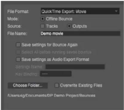
Figure 84-16: Exporting audio plus video to a movie.
7 Choose the appropriate output bundle from the Source menu, and specify a destination folder as usual.
8 If you wish to replace the existing movie, check the Overwrite Existing Files option.
9 Click OK.
10Mac only: The QuickTime export options appear. If you are running MacOS 10.7 or later, set Include film scoring events track as desired.
11Click OK.
Mac only: Exported audio tracks are encoded as Apple AAC in the sample rate of the Digital Performer project. Apple's AAC encoder only supports sample rates up to 48 kHz, so Digital Performer will downsample, if necessary, during the bounce operation.
Video black
If the audio starts before the source video begins or extends past where the source video ends, Digital Performer appends the movie with video black so that the resulting movie matches the length of the audio.
Include film scoring events track
Under MacOS 10.7 or later, this option lets you include film scoring events as part of the video. See “Exporting visual cues” on page 792 for more details.
BOUNCING STEMS
To bounce stems, the basic procedure is as follows:
1 Preview your mix to make sure all tracks to be mixed down are unmuted.
2 Select All.
3 Choose Bounce to Disk.
4 For the source options, choose both Tracks and Outputs.
5 Select each track for which you wish to create a stem file.
6 If you wish to include a full stereo mix as part of your stem export, select your primary output pair (e.g. Main Outs).
7 Enter an appropriate file name as a base name for all the stems.
8 Make the other settings in the Bounce to Disk dialog as desired.
9 Click OK.
THE BOUNCE SETTINGS MENU
After you have saved one or more bounce settings, you can use the commands in the Bounce Settings sub-menu (File menu):

Figure 84-17: Bounce settings menu.
Run Last Bounce Again
Choose Run Last Bounce Again to redo the last bounce operation. This command can be used even if you did not save the last bounce settings.
This command is convenient for bouncing again after you make some further tweaks to your source material. Just remember that the original time range still applies, so if you need to change the length of the bounce time range, or the tracks to be included, you'll need to choose Bounce to Disk to create a new bounce operation.
Burn CD From Disk Image
This command burns an existing Audio CD Image File (with ".acdi" extension) to a CD. See "Audio CD Disk Images" on page 965 for more details.
Multi Bounce
The Multi Bounce command lets you run multiple saved bounce operations in one batch operation. For example, you could save bounce settings for each track for a CD, and then bounce all of the tracks together in one operation, while you get coffee. You could even let a lengthy multi-bounce operation run overnight, if necessary.
The Multi Bounce window can also batch process saved bounce settings from multiple DP projects.
When you choose Multi Bounce, a window appears:

Figure 84-18: Multi Bounce.
If you open the Multi Bounce window while a DP project is currently open, the Multi Bounce window displays all of the bounce operations you have saved in the project (displayed in bold text in Figure 84-18).
Choosing which bounce settings to include Use Shift-click and/or Command/Ctrl-click to select the bounce settings you would like to process. Highlighted items will be included in the batch process; unhilighted items will not.
Add
Click Add to include bounce settings from other DP documents. When you click Add, you'll see the standard file dialog. Choose the project that contains the bounce operations you wish to include, and then click Open. The saved bounce settings from that document then appear in the Multi Bounce window list, as demonstrated below:
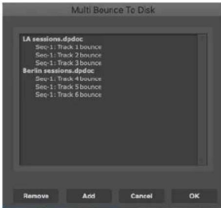
Figure 84-19: Multi Bounce from multiple DP documents.
Remove
If you are viewing bounce settings from multiple DP documents in the list (Figure 84-19), use the Remove button to eliminate a file's bounce settings from the list. Just click one of the file's bounce settings to highlight it and click Remove.
OK/Cancel
Click OK to initiate the multi bounce operation, or click Cancel to abort. During the multi-bounce operation, each file will open (if necessary), and you'll see a status panel that gives you a running update of the progress of the operation:

Figure 84-20: Multi Bounce status panel.
Multi bounce summary report
When a multi bounce operation is completed, a summary window reports the success of each bounce operation, or errors, if any.

Figure 84-21: Multi Bounce summary report.
Initiating Multi Bounce when no DP document is current open
The Multi Bounce command can be chosen even when no DP project file is currently open. This allows you to initiate a multi bounce operation without first opening a DP document. With no DP document currently open, choose File menu> Bounce Settings> Multi Bounce. The Multi Bounce window appears (Figure 84-18) with no items yet listed.
Click the Add button to load in the desired bounce settings from any number of DP documents. When you are finished, the list will show the bounce settings for each document, as demonstrated earlier in Figure 84-19. Shift-click and/or Command/Ctrl-click to select the bounce settings you wish to include in the batch operation, and then click OK.
Edit Bounce Again Settings
Choose Edit Bounce Again Settings (Figure 84-17 on page 967) to rename, delete or assign a key binding to the saved bounce settings in the current DP project.
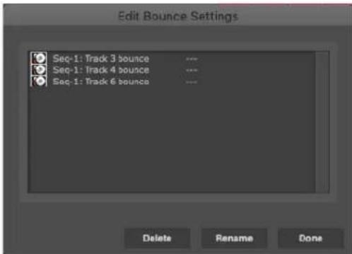
Figure 84-22: Editing saved bounce settings.
Running a saved bounce setting
To run a saved bounce setting, choose it by name from the Bounce Settings sub-menu (Figure 84-17 on page 967) or press its assigned keyboard shortcut, as displayed next to its name in the menu. To assign a keyboard shortcut to it, or change the current keyboard shortcut, use the Edit Saved Bounce Settings command described above.
Edit Audio Export Formats
Edit Audio Export Formats lets you delete and rename saved audio export formats. See “Editing audio export presets” on page 959 and “Saving an audio export preset” on page 39.
Bounce Includes Audio Patch Thru
Normally, the inputs of voice tracks are muted during Bounce to Disk operations so that you don't have to take the time to disable live monitoring on any tracks that may have it, prior to conducting a bounce. However, there may be situations where it is convenient to include a track's monitored input in the mixdown. When enabled (checked), the Bounce Includes Audio Patch Thru menu item in the Bounce Settings menu (Figure 84-17 on page 967) leaves track inputs active during the bounce process. Be careful not to accidentally include unwanted live signals, such as microphones and other live audio inputs.
CHAPTER 85 Mastering
OVERVIEW
Mastering is the process of preparing your mix for final delivery on audio compact disc, in MP3 format, or any other delivery medium of your choice. This chapter discusses several topics related to mastering that are specific to Digital Performer. However, there is much more to know about the art of mastering and the many engineering techniques involved. The internet is an excellent resource for further information. As you learn more about general mastering principles, keep in mind that Digital Performer provides all of the tools you need to achieve even the most advanced mastering objectives.
Master fader....971
Allocating processing power....971
Real-time bounce to disk .....972
Rendering audio ....973
Bounce to disk....974
Delivery....974
MASTER FADER
The master fader is the most important element in your mix. If you are not using a master fader on your mix and are encountering distortion, chances are, you are overloading the mix bus. The solution for this is very simple. Create a master fader and assign its output to the same output as the rest of your faders. This allows you to pull down the over all level of your mix to avoid distortion.
MasterWorks Limiter
The next step is to apply the MasterWorks Limiter to the master fader to control the overall average level of your mix. For complete details, see "MasterWorks Limiter" on page 55 in the DP Plugin Guide. Here is a brief overview of how to get started:
1 Set the master fader at unity gain (0.0 dB).
2 Lower the MasterWorks Limiter ceiling to -0.5dB.
3 Set the MasterWorks look-ahead to 1ms.
4 Set the MasterWorks release to 0.10ms.
5 Be sure dithering is on.
6 Press play in Digital Performer.
7 Gradually bring the threshold down until you see gentle gain reduction in the area of -2 to -4dB. You may have to use the input gain to bring the mix into the range of the limiter.
At this point, you have accomplished a gentle normalization of your audio with dithering.
Experiment with the threshold control to bring up the overall average level of your mix.
Long-throw metering for mastering
Long throw metering is available in the Meter Bridge (“Meter Bridge” on page 885). In addition, the range of the meters in this window can be adjusted, allowing you to focus on a specific amplitude range as explained in “Meter scale” on page 886.
ALLOCATING PROCESSING POWER
When using a native audio system such as MOTU Audio System, you may find it necessary to juggle buffer settings depending on what you wish to accomplish. When finalizing a mix and then mastering it, your goal should be to maximize the amount of processing power available for real time
MOTU Audio System effects. One way to do this is to raise the buffer settings for your audio system. 1024 is a good setting at which to mix.
Higher buffer settings free up more processing power for mixing at the expense of increased input monitoring latency. This may or may not be an issue for you, depending on how go about mixing and mastering your project. In many cases, input monitoring latency only comes into play at the beginning of a recording project when you are first laying down tracks. While monitoring live input during recording, you can reduce the buffer size to eliminate monitoring delay and afterwards raise it again for increased processing power during mixing and mastering.
While mastering, however, your mix may include real-time elements (software synths or MIDI triggered effects, for example) that require that you maintain low buffer settings. In this case, you need to do the best you can to balance your system resources with the demands of these real-time elements of your mix.
If your project contains only audio and MIDI assigned to virtual instruments (e.g. no real-time input from aux tracks from external sources), then you are ready to bounce your project to disk. If your project contains any external real-time sources (MIDI tracks assigned to hardware MIDI Instruments, external processing, virtual instruments, etc.) you have two strategies for finishing your mix:
■ Real-time bounce to disk
■ Rendering
These techniques are discussed in the next few sections.
REAL-TIME BOUNCE TO DISK
Let's say you have a fairly complex project with MIDI tracks submixed externally and their combined audio signal entering Digital Performer via an aux track. You may also have some external virtual instruments (like Propellerhead's Reason) coming into some aux tracks as well. If your mix sounds good at this point, you can perform a real time bounce to disk as follows:
1 Reassign the outputs of all your audio and aux tracks to an unused stereo bus. You may have to create one if one does not exist. It might help to use an audio bundle and give it a name such as 'my mix bus'.
2 Create a new stereo audio track and set the input of the audio track to the newly created bus ('my mix bus'). You may also set the output of your audio track to your original monitor outs so you can monitor the progress.
3 One final touch: rename the new audio track 'final mix'. When Digital Performer writes the new file to disk, the file will assume the track name.
If you open up the Audio Monitor and hit play in the transport, you should see level representing your mix on your mix bus. Now you can rewind to the beginning, and record the entire mix.
External virtual instrument compensation
If you are using a virtual instrument that runs as a stand-alone application alongside Digital Performer (like Propellerhead's Reason), you may wish to compensate for latency by pushing the MIDI tracks assigned to that instrument ahead in time. This can easily be accomplished with the non-destructive Time Shift MIDI plug-in. If your virtual instrument MIDI track has data starting at 1|1|000, you can shift your entire project later by one measure to avoid having the first note of that track disappear.
For virtual instrument plug-ins, Digital Performer provides automatic latency compensation.
External effects compensation
Externally processed tracks can also benefit from latency compensation. For example, you may decide to send a drum submix out to a vintage compressor and feed the result back into Digital Performer's mixing board. If the input buffers are set at 256 samples, for example, you can used the Shift command (Edit menu) to advance your drum tracks by 256 samples.
RENDERING AUDIO
Another strategy for finishing your mix is to render all elements of your mix as audio. This procedure requires more disk space, but these commodities are quite affordable these days. One strong advantage of this approach is complete portability. For example, you may open up the project in the future and find that you don't have access to the same outboard processing gear or virtual instruments. If this is a concern for you, it may be a good idea to render these elements. After all the elements of your mix are rendered as audio, then you can perform a normal, non-real time bounce to disk.
Rendering software MIDI instruments
In most cases, Bounce to Disk can be used to render your virtual instruments as audio. See "Source tracks" on page 957 for more details.
Rendering external MIDI instruments
Recording the audio output of MIDI modules as audio exactly preserves the performance of that instrument.
Some MIDI modules include digital outputs which you may want to take advantage of. If you own many instruments with digital outputs, it may be a good idea to consider a MOTU 308 digital interface. In addition to functioning as a digital patchbay, it allows you to keep all your digital gear wired directly into Digital Performer. This means you can record the output of a sound module without disconnecting the analog outputs.
If you use multiple MIDI modules, chances are good that you are already using a mixer to sum the outputs of these devices. You can render the entire MIDI submix by recording the output of the mixer. Another method is to use an alternative set of outputs or busses to avoid re-patching the outputs of your mixer.
Under some circumstances, you may want to record the outputs of your MIDI tracks individually for more flexibility when mixing in Digital Performer. If you find yourself doing this frequently, you may want to dedicate a set of sends to inputs on your audio interface. Another technique is to employ a patchbay so you can quickly route signals from the mixer to the audio interface. This also eliminates unnecessary additional gain stages between the output of your MIDI module and the input of your audio interface.
Recording individual MIDI tracks presents some opportunities to enhance your mix. You may own an outboard processor that has a certain ‘magic’. Recording individual MIDI tracks through this processor one at a time effectively multiplies the number of instances that you have of this processor.
Rendering external processors
Recording the output of a signal processor does not require any latency compensation as discussed earlier because it does not involve real-time monitoring. This is another advantage to rendering, as it leaves you with one less thing to worry about.
If you feed a Digital Performer disk track to an external signal processor and then feed the processor output back into Digital Performer as a
live input, you can precisely compensate for the delay. See “External effects compensation” on page 973.
Rendering MIDI triggered effects
In a bounce to disk operation, MIDI elements are ignored because bouncing is not a real time process. If you used MIDI triggering of effects in Digital Performer, such as with MasterWorks Gate or Multimode Filter, you will need to capture the real time output of that effect. Create a new audio track and set the output of the original track to a bus assigned to the input of the new track. Lower the hardware buffer setting and record the result. Be sure to mute the original track before you bounce to disk.
BOUNCE TO DISK
Now that you have rendered all elements of your mix to audio tracks, you can now touch up your final mix and bounce to disk. See chapter 84, "Bounce To Disk" (page 953) for complete details. Be sure the Add to soundbites window option is enabled. Name your mix something memorable, such as 'final mix'.
DELIVERY
Digital Performer supports a variety of native file formats: interleaved and deinterleaved Broadcast WAVE and AIFF files at 16-bit, 24-bit, or 32-bit floating point. When you need to export your mix out of Digital Performer, open the Soundbites window, select your 'final mix' file and choose Export Selected Soundbites from the mini-menu. You can export the mix in all of Digital Performer's supported formats and more.
Create an MP3 file
Use Digital Performer's Bounce feature or the Export Selected Soundbites feature mentioned above to export directly to MP3 file format.
Burn a CD
You can bounce and burn to CD in one step from within Digital Performer. See “Bouncing to a CD or disk image (Mac only)” on page 961.
You can also export interleaved files for use with another audio CD burning software, such as Roxio's Toast or Apple's iTunes.
Part10
Synchronization
CHAPTER 86 Receive Sync
OVERVIEW
The Receive Sync command (Setup menu) allows you to ‘slave’ Digital Performer to a wide variety of ‘master’ timing sources. Digital Performer supports all standard MIDI synchronization formats, including MIDI Time Code and MIDI beat clocks with Song Position Pointer data for synchronization with drum machines, hardware sequencers, and other MIDI devices. With a SMPTE-to-MIDI converter such as MOTU’s MIDI Express XT, Digital Performer can sync to audio tape, video, or film, ensuring that events in your sequence happen at exactly the same spot on tape or film every time. Digital Performer also supports sample-accurate digital audio synchronization with devices that support the ADAT and Tascam sample-accurate digital audio synchronization protocols. Digital Performer also has a Tap Tempo feature for synchronizing to prerecorded music, conducting a sequence as it plays back, or simply recording a tempo map in real time.
Receive Sync basics....977
Basic types of sync....977
Using Receive Sync....978
Choosing a SMPTE frame format....978
Choosing a SMPTE start frame....979
Sync to port menu....979
Record while still-framed....979
Sample-accurate sync ....980
MTC (MIDI Time Code)....981
MIDI Beat Clocks....982
Tap Tempo 983
Slaving to external sync 984
Using Tap Tempo 985
Using Tap Tempo while slaved to external sync .....987
Recording with a multitrack analog tape recorder .....988
Converting a click track into a tempo map .....990
Slaving to VITC....992
Synchronization hints....992
RECEIVE SYNC BASICS
Digital Performer supports all standard modes of synchronization: Sample Accurate Sync, MIDI Time Code, MIDI Beat Clocks, and Tap Tempo. These modes are selected in the Receive Sync settings window. When MIDI Beat Clock or Tap Tempo is selected, other parameters appear in the Receive Sync settings window and must be set correctly; the MIDI Time Code and Sample Accurate modes have no other parameters (except for the frame rate). The mode you use depends on the equipment to which you are synchronizing.
BASIC TYPES OF SYNC
The following section describes the common forms of synchronization and the corresponding modes in Digital Performer.
Sample Accurate
Sample-accurate synchronization is the tightest possible synchronization between two devices. It offers the strong advantage of exactly preserving the phase relationship between digital audio tracks in a multitrack project, even when they are not transferred at the same time. For example, if you transfer 8 tracks from the ADAT into Digital Performer, sample accurate sync ensures that they will maintain their exact phase relationship to one another, even if you record them into Digital Performer one at a time.
SMPTE time code
SMPTE time code is an international standard that was developed for film and video work but has proven to be very useful in normal audio work as well. This is an absolute time code, expressing hours, minutes, seconds and divisions of the
second in digital form. It can be recorded on tape or film and read by a special device to convert it to MIDI.
Since SMPTE has no intrinsic tempo information, the sequencer or device converting SMPTE to MIDI must generate its own tempo. Digital Performer's flexible tempo map and frame time display make it ideal for work with SMPTE time code. Because of its accuracy and wide-spread acceptance, SMPTE is the most powerful of the time code formats.
Depending on your converter, you can use the MIDI Beat Clock or MIDI Time Code modes. MIDI Time Code is the easiest and most accurate mode. MIDI Time Code allows the use of Digital Performer's tempo maps, and is far superior to the MIDI Beat Clocks mode.
In addition, MOTU Audio interfaces can slave directly to SMPTE timecode – consult your MOTU Audio interface user guide.
MIDI beat clocks
MIDI Beat Clocks are produced by most MIDI compatible drum machines and sequencers, and by some synthesizers (particularly those with built-in sequencers).
MIDI beat clocks are transmitted 24 times a beat. If the master device changes tempo, the MIDI beat clocks slow down or speed up accordingly; any slave device will follow this tempo change. Most devices that generate MIDI beat clocks also send Start, Stop, and Continue messages; slave devices will start playback, pause, rewind, or play from the current location according to the combination of these messages received. In addition, many devices send Song Position Pointer data. These messages set the current location for playback, much like setting the Counter in Digital Performer. To sync Digital Performer to devices using these MIDI messages, use the MIDI Beat Clock mode in the Receive Sync settings window.
Tap Tempo
Tap Tempo is Digital Performer's real-time tempo control facility. This form of synchronization slaves Digital Performer to a 'tap' entered from your MIDI controller. Digital Performer receives a MIDI event for each tap and computes a tempo based on the current meter, the click value, and each event's distance in time from the previous event. Any tempo information in the sequence is ignored while Digital Performer is slaved to Tap Tempo. Tap Tempo supports both recording and playback, so your tap can conduct or be recorded into any sequence, empty or finished. When you record in Tap Tempo, each tap becomes a tempo event in the Conductor Track. Even if you have a minimal MIDI setup, you have everything you need to use Tap Tempo synchronization.
USING RECEIVE SYNC
The following sections explain the Receive Sync settings (opened from the Setup menu).
CHOOSING A SMPTE FRAME FORMAT
If you are slaving to any sync type that involves SMPTE time code, or if the work you are doing in Digital Performer requires that you reference SMPTE time code, be sure to choose the correct SMPTE frame format at the top of the Receive Sync settings window as shown below in Figure 86-1. This setting is the same setting as the Frame Rate selection in the Setup menu.
All standard SMPTE frame rates are provided: 23.976, 24, 25, 29.97 drop, 29.97 non-drop, and 30 fps. There are also some nonstandard frame rates available (see “Nonstandard frame rates” on page 100 for details).

Figure 86-1: Choosing a SMPTE time code frame format.
CHOOSING A SMPTE START FRAME
When slaving Digital Performer to SMPTE Time Code (via MTC or LTC), you need to specify a SMPTE start time for the sequence. This is the frame location at which the sequence begins to play. See “Setting the start time” on page 203.
SYNC TO PORT MENU
The Sync to Port menu lets you choose the source from which Digital Performer will receive MIDI timing information (beat clocks, MIDI Time Code, etc.)

Figure 86-2: The Sync to Port menu.
Any device in your your MIDI device configuration (Setup menu > Bundles > MIDI Devices tab) that has the MIDI Beat Clock or MIDI Time Code attribute checked will appear in this menu. Choose Any Port to allow Digital Performer to slave to any timecode that it receives, regardless of its source.

Figure 86-3: Any device that has the 'Transmits MIDI Beat Clock' or 'Transmits MIDI Time Code' properties checked will appear in the Sync to Port menu in Digital Performer's Receive Sync settings window.
The Receive Sync preferences has an option called Record while still-framed. Without this option checked, Digital Performer drops out of record as soon as you stop the tape after a record pass while slaved to tape; Digital Performer will not record again until you press the Record button. This prevents unintentional recording while cueing and accidental loss of Undo Record. When this option is checked, Digital Performer stays in record when you stop the tape so that you can record a hit while parked on a frame. This is particularly useful when frame-advancing while slaved to a VITC-compatible synchronizer such as a MOTU Video Timepiece or Digital Timepiece, which provides accurate frame-advancing. Unless you are recording while frame-advancing, we recommend that you leave this option unchecked.
Figure 86-4: Sample-accurate sync settings. Notice that there is no 'Sync to Port' setting for sample-accurate sync, since Digital Performer directly accesses the audio hardware for sample address information.
If you are using Digital Performer with a MOTU PCI-424 system, MOTU 828mkII, or any other sample-accurate audio interface, Digital
Performer can achieve sample-accurate synchronization with ADATs or any external recording device that supports sample-accurate synchronization.
This allows you to transfer digital audio — entirely in the digital domain — between Digital Performer and an ADAT (or similar ADAT-compatible digital audio recorder) via ADAT optical cables (or other digital audio format) with single-sample accuracy. For example, if you record some audio from the ADAT into Digital Performer, and then send it back to the ADAT, it will be placed at exactly the same location — to the very sample — from where it originated (assuming you don’t move it while it’s in Digital Performer). You could transfer audio back and forth digitally between Digital Performer and the other device as many times as you like, and the audio will not drift even one sample earlier or later, no matter how many times it is transferred between the two devices.
Sample-accurate transfers like this can also be achieved with Tascam family tape decks (such as the DA-38, DA-88, or DA-98) via a 2408mk3/PCI-424 system. A MOTU Digital Timepiece is required.
Digital audio I/O is required
Sample-accurate digital transfers require a digital audio interface such as a MOTU 828x, which supports sample-accurate sync. MOTU's audio interfaces provide a variety of digital audio formats, including 8-channel ADAT optical, AES/EBU and S/PDIF. For details, visit www.motu.com/products.
MOTU PCI-424/FireWire hardware setup
If you have MOTU PCI-424 or FireWire Audio system, refer to your hardware manual for specific details about how to connect your system for sample-accurate sync to an ADAT or Tascam tape deck.
Digital Performer settings
For sample-accurate sync, choose the Sample-accurate sync setting as shown above in Figure 86-4. No additional sync settings are required. Notice that the Sync to Port setting disappears when you choose Sample-accurate sync. This is because Digital Performer accesses the sample address information directly in the hardware (via the hardware driver, e.g. the PCI-424 driver for the MOTU 2408mk3, or the MOTU FireWire Audio driver for the MOTU 828mkII FireWire audio interface).
Hardware driver settings
Choose Setup menu>Configure Audio System>Configure Hardware Driver and make the appropriate clock source setting for the hardware you are using. For the 2408mk3, choose PCI-424: ADAT from the Clock Source menu as shown below.

Figure 86-5: The clock source setting for sample-accurate sync. If you have multiple interfaces, make sure that these two settings match.
Transport control from Digital Performer via MMC
If you have a MIDI Timepiece AV or other MMC-capable ADAT synchronizer and would like to control everything from Digital Performer's transport controls via MMC, open the MMC window and enable MMC. This puts Digital Performer in Slave to External Sync mode. Make sure your MIDI Timepiece AV (or other MMC synchronizer) is on-line.
Optical input/output settings
To transfer audio digitally from another device to Digital Performer, be sure to choose a digital input for the track you will be recording into. Conversely, when you want to transfer audio from Digital Performer to the other device, make sure you've chosen digital output assignment of the track you want to transfer.
MTC (MIDI TIME CODE)

Figure 86-6: Slaving to SMPTE time code. As you can see, there are no extra options for SMPTE timecode sync.
Use the MTC mode when you are slaving Digital Performer to SMPTE time code via a converter that supports MTC (MIDI Time Code).
SMPTE time code (an analog audio signal) is fed from a master source such as an audio tape recorder, video tape recorder, or SMPTE generator into a SMPTE-to-MIDI converter such as a MOTU MIDI Express XT, which translates the SMPTE time code into MIDI timing information. This MIDI timing information is produced in the form of MIDI time code (MTC), an industry standard format.
MTC sync mode is a simple and direct way to slave Digital Performer to an external source generating SMPTE time code. Digital Performer is able to lock to the frame times of the master, insuring precise synchronization between devices. In addition, Digital Performer remains under its own tempo control, allowing you to program sophisticated tempo maps while slaved to time code.
To use MTC sync mode, you must have a SMPTE-to-MIDI converter that supports MTC, such as a MIDI Express XT from MOTU.
There are no special options to select in the Receive Sync settings window: when in MTC mode, Digital Performer simply responds to timing data directly.
After Digital Performer is locked to the master, there is no need to use Digital Performer's main transport controls unless you wish to record. Digital Performer will start, stop and locate under control of the master. Also upon lockup, if Click is enabled, Digital Performer will click in the meter specified at 1|1|000 or will default to 4/4.
You can put Digital Performer into play or record either before or after you start rolling tape. In either case, Digital Performer will lock up quickly.
Using MTC sync mode
After you have chosen MTC mode, slave Digital Performer as explained in "Tap Tempo" on page 983.
MIDI BEAT CLOCKS

Figure 86-7: The MIDI Beat Clock options.
This is a standard form of synchronization between two MIDI devices. When the MIDI Beat Clocks option is selected, Digital Performer can sync to a master device that is generating MIDI clock signals. If you want to slave Digital Performer using a drum machine, external sequencer or other MIDI device as master, use this mode. This mode may also be used with a SMPTE converter that generates its own tempo map. In MIDI Beat Clocks mode, Digital Performer's tempo will match that of the master device; Digital Performer's tempo features are disabled.
Implementations of MIDI have evolved over the years. As a result, not all devices transmit and send MIDI clock signals in the same way. Digital Performer provides several options for maximum synchronization compatibility with your master device:
24 clocks per metronome click/ 24 clocks per quarter note
Some manufacturers make devices which send 24 clock signals per beat (one click of the device's metronome) instead of the standard 24 clocks per quarter note. This method is very useful when there are meters which do not use the quarter note as the beat unit: 3/8, 5/16, etc. In 6/8, for example, there might be a metronome click every three eighth notes; in 4/1, the metronome would click once every whole note. If you were using a less common meter such as 5/32 or 3/16 + 4/16, using the quarter note as the timing base would not be very useful. Instead, use the 24 clocks per metronome click option.
Start on any clock
When this option is checked, Digital Performer will automatically start if it receives a time clock even if no start or continue command was received. This option is necessary when using some early MIDI devices which don't send start or continue commands, only timing clocks.
First clock is time 1
When this option is checked, Digital Performer interprets the first MIDI clock signal it receives as the second timing clock of the sequence, 1/24th of a beat after the beginning. Devices manufactured recently send the first clock signal (time 0) after the start command for the sequence. Some earlier devices assume the start command to be the first clock signal. The first clock signal they send would
be 1/24th of a beat after the beginning. If you are using one of these devices, you should check this option.
Since manufacturers rarely explain this aspect in their documentation, you may not know if your device behaves this way. The best way to find out is to experiment: set the metronome to the slowest possible tempo, play both devices (with Digital Performer as slave) and listen for discrepancies in attacks and beat alignment. The difference of 1/24th of a beat is very audible at a slow tempo. If Digital Performer seems slightly behind the master device, try checking this option.
Default beat clock settings
The default settings reflect the most commonly used MIDI standards. It is best to set them this way before choosing to alter them:
■ 24 clocks per quarter note
■ start on any clock: unchecked
■ first clock is time 1: unchecked
Using MIDI Beat Clocks mode
After you have made the MIDI Beat Clock settings as needed, slave Digital Performer as explained in "Tap Tempo" on page 983.
TAP TEMPO
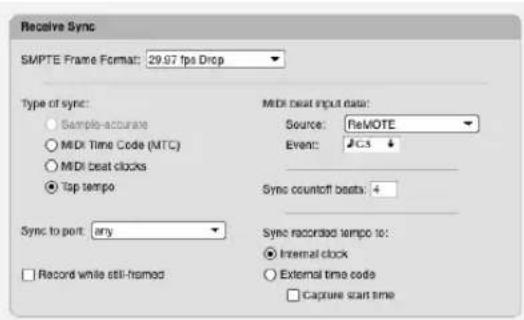
Figure 86-8: Tap Tempo settings.
Tap Tempo is Digital Performer's real-time tempo control feature. Tap Tempo lets you slave Digital Performer to a tap entered from any MIDI controller before, during, or after the recording of your sequence. You can ‘conduct’ an existing sequence by tapping the tempo, complete with accelerandos, ritards, and rubato passages; Digital Performer will follow precisely. More importantly, you can record your tap into the Conductor Track for use in subsequent playback and recording.
Tap Tempo can be used during virtually any stage in the creation of a sequence. For example, if you have acoustic music on tape, two completed tracks in Digital Performer, and three more Digital Performer tracks to record, you can ‘teach’ the two existing tracks to follow the prerecorded music. Your remaining tracks will be recorded into a sequence that has all of the temporal nuances of the prerecorded music.
Preparing for Tap Tempo
The following are general points to consider when preparing to use Tap Tempo sync.
Establish a meter
When slaving to Tap Tempo, Digital Performer must know how many of your taps to group as one measure. Before recording or playing back a passage in Tap Tempo mode, make sure you've entered the correct meter using the Change Meter command (Project menu>Conductor Track>Change Meter).
Establish a metronome click value
Your taps correspond to the current metronome click value, specified using the Change Meter command. For example, the tempo of a 4/4 passage can be tapped and expressed in whole notes, one tap per measure, or in sixteenth notes, sixteen taps per measure. Each tap becomes a tempo change event, so the smaller the click value, the higher the resolution of the resulting tempo map.
Choose a tap source
You can use any standard MIDI event as your tap source. Digital Performer will interpret this MIDI event as a tap whenever it occurs on the specified input channel. If you plan to record music while slaved to Tap Tempo, choose a combination of MIDI event and channel that won't be needed in the musical passage. For example, let's say you're tapping C3 on a controller keyboard, transmitting on channel 1. The result? Any other C3's transmitted on the same channel will not be recorded. Again, this is only true for C3's transmitted on channel 1. C3's transmitted on other channels will be recorded normally.
Note that although pitch bend and controller events are acceptable as tap sources, the most common controls for sending them (wheels, joysticks) make reproduction of a single, specific value difficult. For example, to define your tap you enter a pitch bend value of 392 using a pitch bend wheel. To slave Digital Performer, you'll need to generate values of 392 or higher — you send a 392 value by going precisely to it, but also by going past it. That much is easy, but remember that Digital Performer will treat only the events with 392 values as taps. All other values sent by your mod wheel will be recorded and interpreted as normal pitch bend events. This makes bend and controller events less practical tap choices than events with precise triggers or more limited values, such as a note or a Controller #64 (sustain pedal) event.
MIDI beat input data
Source
Choose the MIDI device you will be tapping from in the menu provided.
Event
Specify the MIDI event you wish to use as a tap. Tab to the Event box or click in it, then enter a MIDI event from any MIDI controller connected to the specified port (play a note, tap a sustain pedal, etc.). The event appears, highlighted; click on the highlighted event if you wish to change it. You can use any standard MIDI event as a tap source.
Countoff beats
Specify the number of times you wish to tap as a countoff. The default number of sync countoff beats is four, but the countoff can be any number between 1 and 127. If you enter a number outside this range, the computer will beep when you click the OK button and the number will be highlighted. If this happens, click on the highlighted value and enter a new one.
Using Tap Tempo mode
After you have made the Tap Tempo settings as needed, follow the steps explained in “Using Tap Tempo” on page 985.
SLAVING TO EXTERNAL SYNC
After you have chosen one of the desired sync modes already discussed in this chapter, slave Digital Performer to an external source as follows (refer to the next section for Tap Tempo):
1 Select Slave to External Sync from the Setup menu.
This puts Digital Performer into slave mode, waiting for sync information from an external device.
2 Click on the Play or Record button in the main transport controls.
The Play button will flash on and off, meaning that Digital Performer is waiting for sync information to start.
3 To start Digital Performer, start the external device.
When Digital Performer is locked and playing, the Play button will turn blue. When locked, Digital Performer will follow, start, stop and rewind under control of the master.
4 To terminate the lock up with the master, click on the Stop button.
Clicking on the Stop button will both stop Digital Performer and remove it from the master's control. This can be done at any time. To return to normal operation, turn off Slave to External Sync by reselecting it from the Studio menu.
USING TAP TEMPO
To use Tap Tempo mode:
1 Choose Slave to External Sync from the Setup menu.
This puts Digital Performer in slave mode; it is now waiting for sync information from an external source.
2 If you wish to record the tap into your sequence, record-enable the Conductor Track. Your tap will be stored as tempo change events in the Conductor Track and used in subsequent playback and recording. Existing tempo changes will be replaced. Other Conductor Track information will be unaffected.
3 If you wish to record music into your sequence, record-enable the desired tracks.
If you wish to record the tapped tempo and music simultaneously, or record music onto more than one track, choose Multi Record from the Studio menu. Specify the record device for each track that is record-enabled. The Conductor Track will record from the device specified in the Receive Sync settings window.
4 Press the Play or Record button in the main transport controls.
The Play button will flash, meaning that Digital Performer is waiting to receive sync information. Overdub mode will not function on the Conductor Track; that is, recording in either normal or overdub mode will erase any existing tempo events.
5 If you will be tapping along with a prerecorded passage, start playback of the recording.
Ideally, the prerecorded music will have a sufficient countoff so that you can tap the number of countoff beats specified in the Receive Sync settings window.
6 Begin 'tapping' the MIDI event that you designated in the Receive Sync settings window.
Digital Performer will listen for the specified number of countoff beats to predetermine the tempo for the beginning of playback or recording. When Digital Performer has received the countoff, playback or recording will begin.
7 Tap the desired tempo and tempo changes.
Make your tap as expressive and dynamic as you wish; Digital Performer will follow. The Counter display will update as you tap.
8 To end recording or playback, press the Stop button in the main transport controls.
Don't be alarmed if the computer pauses after you stop recording. Digital Performer is calculating precise tempo changes from the taps you just recorded.
9 Take Digital Performer out of slave mode by choosing Slave to External Sync from the Setup menu.
10If you recorded your tap, you can hear the results by rewinding the sequence, making sure the metronome under Conductor Track tempo control, and pressing Play.
Your sequence will play back using the tempo that you tapped. If you are not satisfied with the results, you can use the Undo Record command in the Edit menu and then repeat the above process. You can make adjustments by rerecording certain sections and by editing individual tempo changes in one of the Conductor Track's edit windows.
Tapping to prerecorded music on tape
You can use Tap Tempo to record a tempo map while Digital Performer is slaved to tape—or, more accurately, referenced to external time code. You can record a tempo map that matches the music on tape, allowing you to perfectly synchronize your sequence to the prerecorded music. This process is explained in detail in “Using Tap Tempo while slaved to external sync” on page 987.
Hints for using Tap Tempo
Here are some ways to use Tap Tempo.
Recording music simultaneously
If you plan to record music simultaneously with your tap, choose a tap event that doesn't require use of your hands. Controller #64, sustain, is usually triggered by a foot pedal and is a good choice for a tap because it has only two values: On or Off.
Further, Digital Performer will let you use either value for your tap.
Using alternative tap values and sources
You can set the tap as an Off value for a particular note or controller:
1 In the Receive Sync settings window with Tap Tempo chosen, Tab to the Event box.
2 Depress the note or controller, leaving it depressed.
For example, push a modulation wheel away from its 'zero' location. The controller number and its value will appear in the box, highlighted.
3 Without releasing the note or pedal, click on the highlighted Event value.
4 Release the note or pedal.
To continue the example, let the mod wheel spring back to its zero location. The Event box will show Off or 0 as the tap value.
So far, our examples of using Tap Tempo have involved tapping a MIDI instrument to ‘teach’ Digital Performer the temporal details of a sequence. When you tap, you simply send a MIDI event and Digital Performer does the rest. This means you can use any MIDI sequencer to load its own tempo map into Digital Performer — just program the sequencer to play a song’s worth of quarter notes while Digital Performer is slaved to Tap Tempo sync.
Yet another way of sending Digital Performer a tap is to use a device that converts an audio click into a MIDI event. A click or other regular, amplified signal (a click track on tape, a miked rim shot, etc.) can be fed into such a device and converted into MIDI events from which Digital Performer can generate a tempo map.
Punching in a tempo
AutoRecord can be used with Tap Tempo to 'punch in' tempo changes for a section while preserving the tempi outside that section. Enter the Punch In and Out times in the Auto-Record bar, found in the Control Panel, click on the Auto-Record button, then follow the applicable steps above. (Don't be alarmed if both the Play and Record buttons go grey at first; the Play button is
waiting for sync information, and the Record button is waiting for the Counter to reach the punch In location.)
Remember also that slaving Digital Performer to Tap Tempo disables the sequence's existing tempo map. So when you start playback in Auto-Record mode, even though Digital Performer will only record taps from the In location to just before the Out location, you will have to tap throughout the pass. Give yourself the most accurate temporal ‘context’ — the tempi before and after the punch-in passage — as is possible, so that the recorded section will fit smoothly into the rest of the sequence. As always, you can fine-tune all tempo change events in the Conductor Track.
USING TAP TEMPO WHILE SLAVED TO EXTERNAL SYNC
You can use Tap Tempo to record a tempo map while Digital Performer is slaved to tape—or, more accurately, referenced to external time code. You can record a tempo map that matches the music on tape, allowing you to synchronize your sequence to the prerecorded music.
This process can be performed in a more precise fashion if you have an audio click track recorded on the tape and a click-to-MIDI converter such as a MOTU MIDI Express XT.
Preparation
The following are general points to consider before tapping tempo to prerecorded music:
Before you begin, establish SMPTE synchronization to tape. This is necessary for two reasons: 1) Digital Performer needs to receive a timing reference from the tape while creating the tap tempo map, and 2) later on, after you successfully record the tempo map, you will be using the SMPTE to lock the sequence to the tape. To establish SMPTE synchronization, see chapter 86, "Receive Sync" (page 977).
After you have set up SMPTE sync, set up Tap Tempo. To do so, simply follow the directions in the Receive Sync chapter for setting up Tap Tempo, as explained in “Tap Tempo” on page 983. Test it to be sure that when you tap, Digital Performer does indeed follow your taps. This will ensure that you have the proper channel and event for Tap Tempo mode. Remember, you may also need to set up a meter map in the sequence that matches the meter map of the music on tape.
If possible, set up two full measures of countoff on the tape before the first downbeat of music. This will be extremely helpful to your accuracy when tapping the first downbeat, which is the most important downbeat because all subsequent taps—the entire tempo map—will be referenced to its exact location.
Setting up Tap Tempo
After you have made these preparations, you are ready to begin. To Tap Tempo to prerecorded music on tape:
1 Open the Receive Sync settings (Setup menu).

Figure 86-9: Receive Sync settings for Tap Tempo while slaved to external time code.
2 Set the Sync to port option to Any Port.
3 Select the Tap Tempo option.
4 Choose the Tap Tempo settings as described earlier in "Preparing for Tap Tempo" on page 983.
If you are feeding a click track through a click-to-MIDI converter, make sure that the Tap Tempo event setting matches the MIDI event being generated by the converter.
Also be sure that the number of countoff beats you choose here corresponds in a useful way to the number of countoff beats on tape. For example, ideally, you should have 2 measures of countoff on tape; if so, set the countoff beats here to 1 measure. When you roll the tape, you can get ready during the first measure of countoff, tap along for the second measure, and hit the downbeat right on the money. If you don't have an countoff on the tape, you will have to develop a system that works best for you. You might try just one countoff beat.
5 Check the External time code option.
Digital Performer will now reference your taps to incoming timecode.
6 Select the Capture start time option.
This option makes Digital Performer remember the exact SMPTE frame of your first tap (excluding the countoff beats) so the sequence will start at the correct SMPTE time.
The procedure
Now you are ready to go:
1 Record-enable the Conductor Track.
2 Choose Slave to External Sync (Setup menu).
3 Press the Record button.
4 Get ready to tap, and roll the tape.
5 Listen for the countoff, and 'tap' along with it such that the first downbeat of the sequence corresponds to the first downbeat of music on tape.
Digital Performer automatically remembers the exact SMPTE time of your tap on the first downbeat of the sequence and saves it as the Chunk start time. When you later slave the sequence to tape, Digital Performer will automatically start the sequence at the correct SMPTE time.
6 Tap along with the music as accurately as possible.
Remember that synchronization later on will only be as accurate as the accuracy with which you tap in this procedure.
7 To end recording, press the Stop button in the main transport controls.
Don't be alarmed if the computer pauses for a while after you stop recording. Digital Performer is calculating precise tempo changes from the taps you just recorded.
Listening to what you have done
Now that you have recorded the tempo map, try slaving Digital Performer to the tape using your usual method of synchronization, such as Direct Time Lock or MIDI Time Code, in the Receive Sync window. Also, make sure that the Metronome is under Conductor track tempo control. You will now be able to playback, rewind, or fast forward anywhere in the song on tape, and your Digital Performer sequence will exactly reproduce your tapping performance with respect to the music on tape. If you tapped accurately, Digital Performer will play along accurately. If you are not satisfied with your tapping performance, just try again.
RECORDING WITH A MULTITRACK ANALOG TAPE RECORDER
Let's look at an example that illustrates how you might go about recording a Digital Performer project with a multitrack analog tape recorder.
You are recording a five-minute song in the studio. You've preproduced the drum and synthesizer track with Digital Performer. Now you want to record guitar and vocal tracks onto tape using live players. You plan to use a synchronization code conversion box (a converter) to translate audio synchronization code recorded on tape into MIDI timing data. Let's assume that you are using a SMPTE-to-MIDI converter such as the MOTU MIDI Express XT.
Synchronizing with SMPTE
The first thing you should do when you get to the studio is to “stripe” (i.e. record) one track of your multi-track tape with an audio sync signal. For this example, let’s assume you are using SMPTE time code. Start striping the tape at time 0:59:00:00. We recommend that you use 30 frames per second, non-drop-frame code, unless you have a specific reason to use one of the other frame rates. Continue for at least 7 minutes; you should always have at least a minute of time code on the tape prior to the start of your song, and you should record plenty of extra time code at the end in case you decide to lengthen the song at some point. Many people stripe the whole reel straight out of the box with one continuous time code track. Striping may take some time; get it started first thing upon arriving at the studio, so that it will be finished by the time you get everything else set up for recording.
Now, set up Digital Performer to play in sync with the multi-track. Feed the time code from the tape into your SMPTE to MIDI converter. Connect the converter to the computer; some converters connect directly, others have a MIDI Out which must go to the MIDI In of an interface connected to the computer. If you have a MIDI Express XT, no additional connections are necessary beyond the normal connection to the computer.
Use a converter that supports MIDI Time Code and set the appropriate mode on the converter (to lock to SMPTE). Choose Receive Sync from the Setup menu. Choose the correct port (Sync to port:) and MTC. Close the Receive Sync preferences window.
Let's start the song at time 1:00:00:00 on the tape (this is a minute after the start of the time code). Change the Chunk Start Time to 1:00:00:00 + 0 time code bits for the frame time. Set the other values as you wish. OK the dialog box.
Set the frame rate correctly in Digital Performer in the Receive Sync settings window. Choose the correct frame rate; use 30 frames per second unless you have a specific reason to use another format.
Enable Slave to External Sync in the Setup menu. Press the play button in the transport; it will begin to flash. At this point, Digital Performer should be slaved to the tape. Display frame time in the counter, and roll the tape from before the time code. Make sure Digital Performer starts, stops, and follows the tape when you wind through the tape.
For overdubbing, you need to provide your players with a reference mix of the song. You can have Digital Performer sync live to the tape and send the players a cue mix. Or, you might find it easier to just place a scratch mix on one or two of the tracks of the multi-track. That way, you won't have to worry about Digital Performer while recording. If your session is spread out over several dates, putting a scratch mix on the tape will save you having to set up your computer and synthesizers every time.
When you get to the final mix, you have two choices. You can mix from Digital Performer playing slaved to the tape. This provides better sound quality, as the synthesizers are first
recorded on the master tape. On the other hand, you may wish to record each synthesizer part on a separate track of the multi-track. This has several benefits. Since the tracks are recorded one at a time, each track can use all of your synths to create a sound. Blending several synthesizers together often creates a more full-bodied sound. Also, if you have limited outboard effects gear, you can record each track with effects, allowing you to reuse what equipment you have.
When recording a single part to tape, we recommend you turn off the play-enable buttons in the tracks window for all tracks except the one you are recording. When you do this, Digital Performer completely ignores the other tracks, letting it concentrate all of the computer's processing power on playing one part. If you use the Solo button instead, Digital Performer will scan the other parts while playing. If you have dense, complicated music, or lots of continuous data, this may cause the computer to become bogged down during playback.
When recording each part separately, you can slide individual parts slightly ahead or behind to compensate for delays in your synthesizers, or the specific sounds. For example, string parts often need to be attacked ahead of the beat in order to sound on the beat.
With sampling synthesizers, you may find that some sounds have as much as 100 milliseconds of “dead air” at the beginning of the sample, which results in that much delay between turning the note on and hearing any sound.
To slide a part, just adjust the start time relative to the start time the other parts were recorded with. For example, if you did have a sample with 100 milliseconds of dead air at the start, you could set the start time to 0:59:59:27 + 0 time code bits. That's 3 frames ahead of the other parts, and at 30 frames per second, 3 frames is 1/10th of a second, or 100 milliseconds. Your sample's audible attack times will now be aligned with those of the other parts.
It's best to slide parts by ear — just keep trying different start times until the part seems most lined up.
CONVERTING A CLICK TRACK INTO A TEMPO MAP
With a click-to-MIDI converter, such as MOTU's MIDI Express XT you can convert an audio click track into a MIDI event. This allows you to convert the click track into a tempo map in a Digital Performer sequence's Conductor track. You can even record the tempo map while Digital Performer's time base is referenced to SMPTE time code, allowing you to accurately synchronize a Digital Performer sequence to prerecorded music.
Before attempting to convert the click track into a tempo map, make sure that the MIDI Express XT is successfully converting the audio click into MIDI data and transmitting the data to Digital Performer and the computer.
Verifying incoming MIDI clicks with the MIDI monitor
To verify incoming MIDI clicks from the MIDI Express XT:
1 Make sure that an audio cable is plugged into the Pedal A jack on the rear panel of the MIDI Express XT.
2 Use the ClockWorks utility to configure the Pedal A jack for click-to-MIDI conversion.
3 Roll the click track on tape.
As the click is being received by the MIDI Express XT and converted to MIDI, the COMPUTER OUT LED should begin to blink,
indicating that the MIDI Express XT is sending the MIDI click event to the computer and Digital Performer.
4 Open Digital Performer's MIDI Monitor window.
5 A channel light will flash if the MIDI click is being successfully received by Digital Performer.
If none of the channel lights flash, check your connections and try again.
Setting up Tap Tempo
The next step is to set up Tap Tempo for external sync. See “Using Tap Tempo while slaved to external sync” on page 987.
Checking Tap Tempo
Before recording anything, check to make sure Digital Performer will follow the MIDI clicks sent by the MIDI Express XT.
1 Choose Slave to external sync from the Setup menu.
2 Press the Play button.
3 Roll the tape.
After a few measures or so of countoff click, the sequence will begin to play back, following the clicks on tape. If not, check the MIDI Monitor window to make sure Digital Performer is receiving the MIDI click. Also check the Tap Tempo options in the Receive Sync settings window.
4 Stop the tape and rewind it to the beginning of the cue.
You are now ready to record the tempo map.
Recording the Tempo Map
If you will be synchronizing the sequence containing the new tempo map to the click track using SMPTE time code, make sure that you:
■ already have SMPTE time code recorded on one track and the click recorded on another
■ already have Digital Performer and the MIDI Express XT set up for SMPTE synchronization such that when you roll the tape, Digital Performer is receiving both the MIDI click and MIDI Time Code at the same time
■ have selected the External time code and Capture start time options in the Receive Sync settings window
Please note: if you want to be able to synchronize the sequence to the click track via SMPTE, it is absolutely necessary that Digital Performer is receiving both the MIDI click and MTC when you record the tempo map.
To record the tempo map:
1 Record-enable the Conductor track in the Tracks window.
2 Press the Record button in the main transport controls.
3 Roll the tape.
If you chose the Capture start time option and are referenced to time code, Digital Performer will remember the exact SMPTE frame of the tap that is the first downbeat and automatically remember to start the sequence at that SMPTE frame when you lock the sequence to SMPTE afterwards.
4 When you are finished recording, stop the tape.
Digital Performer may take a few moments to process the new tempo data.
You now have a new tempo map the matches the click track on tape.
Locking the recorded tempo map to tape
If you recorded the tempo map referenced to time code, you can now lock the sequence to tape. Just choose the MTC option in the Receive Sync settings window, make sure the Metronome is under Conductor track tempo control, and roll the tape. The Capture start time option automatically sets the Chunk SMPTE start time, so the first downbeat of the sequence should occur at exactly the first click downbeat (not including countoff beats, of course).
SLAVING TO VITC
VITC (Vertical Interval Time Code) is SMPTE time code that is recorded directly in the video signal, freeing up both audio tracks and allowing lockup to be maintained while freeze-framing or frame-advancing the video. To slave to VITC, you need a VITC synchronizer, such as a MOTU Digital Timepiece.
SYNCHRONIZATION HINTS
When locking to external SMPTE synchronization, you can shift parts forward and backward in time to compensate for the numerous time delays in a complex system (each device used in a MIDI path introduces at least 2 milliseconds of delay) or to adjust for envelope delays in certain synthesizer patches (such as strings or any other slow-attack patch).
When recording in external sync, the Record button is turned off every time the master device stops or rewinds. This is a safety precaution, to prevent accidental erasure of previously recorded data. To record in external sync, start the master device, wait for Digital Performer to lock up, and then press the record button. Many digital effects devices, like reverbs, delays, equalizers, and even mixers, allow MIDI control. By using Digital Performer with a time code converter to sync to your multi-track tape recorder, you can automate effects changes and other aspects of mixing accurately and flexibly. Read cue points from Digital Performer's counter, or use the Record Hits feature in the Markers window to find locations to insert patch changes and controller information to control your MIDI devices. Alternatively, use the sliders, switches and pedals of your controller keyboard or MIDI mixer to record your mix in real time, then use Digital Performer's editing features to correct any problems.
Setting a countoff before sequence start while slaved to tape
If you are working in a studio situation where you need a countoff before the beginning of the sequence while slaved to tape, here is how you can set up the Digital Performer's countoff feature:
1 Choose an option in the Click preferences that will enable the click during Digital Performer's countoff.
For example, choose the Always Click or Only during countoff option.
2 Set the number of measures you would like for the Countoff.
Do so by Option/Alt-clicking the Countoff button and typing in the number of measures.
3 Make sure that the Click is enabled.
The Click item on the Studio menu must be checked.
If you now rewind well before the sequence start time and roll the tape, Digital Performer, as it counts down, will begin the countoff at the appropriate number of measures before the downbeat of the first measure.
CHAPTER 87 Audio Sync
OVERVIEW
Digital Performer has a complete range of synchronization capabilities, from sample-accurate sync to tap tempo sync. However, the accuracy with which you can synchronize audio tracks in Digital Performer to external devices depends on the audio hardware you are using with Digital Performer. Can the audio hardware continuously resolve to an external time base such as word clock? Does it support sample accurate sync? In regards to synchronization, audio hardware falls into the general categories shown below. These three synchronization scenarios are discussed in this chapter.
Sample-accurate sync ....996
Frame-accurate sync....997
Sync and the computer's built-in audio ....998
Audio hardware
category Description Example Sync formats
Is audio
resolved? Precision
| Sample-accurate Digital Performer and its audio engine both slave to sample addressMOTU 2408mk3provided by the external sample-accurate device via a sample-accurate synchronizer. | MOTU 2408mk3MOTU 828mkII | Digital Performer:sample addressAudio: ADAT sync | Yes | Sample-accurate | |
| Frame-accurate Digital Performer's audio engine resolves to word clock while Digital Performer slaves to MIDI Time Code, both provided by a word clock/SMPTE synchronizer | MOTU 24I/O Digital Performer:MIDI Time CodeAudio: word clock | Yes Usually a quarter of a SMPTE frame or better. | |||
| Unresolved | Digital Performer slaves to MIDI Time Code, but the audio engine runs on its own under its own internal clock. | computer built-in audio | Digital Performer:MIDI Time CodeAudio: none | No | Drifts over time—the longer playback continues, the further audio may drift. |
Figure 87-1 below shows how to set up sample-accurate synchronization with ADATs via a MOTU 828mkII and a sample-accurate synchronizer such as a MOTU MIDI Timepiece AV. The basic setup, as well as the software settings, are similar for the MOTU 2408mk3/PCI-424 card or other sample-accurate audio hardware. Connect the MOTU 828mkII (or
2408mk3's PCI-424 card) to the end of the ADAT chain and make the software settings shown below. If you have a MIDI Timepiece AV or other MMC-compatible synchronizer, you can set it up as the master of the ADAT sync chain and then use Digital Performer's MIDI Machine Control features to give you control over everything from Digital Performer's transport controls.
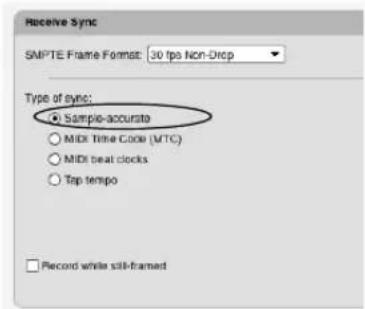
In Digital Performer, choose the Sample-accurate option in the Receive Sync settings (Setup menu).
Computer running Digital Performer
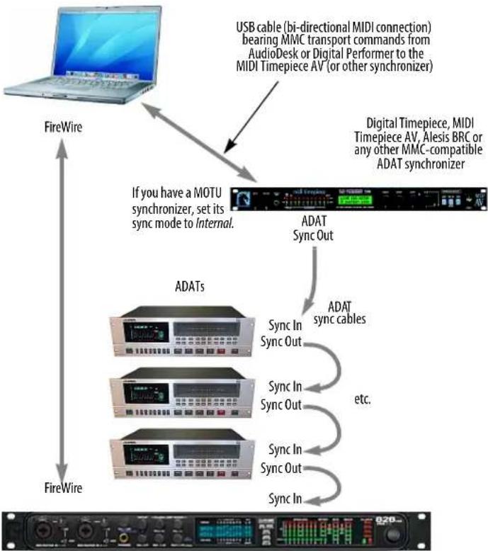
flowchart
graph TD
A["FireWire"] --> B["ADATs"]
B --> C["If you have a MOTU synchronizer, set its sync mode to Internal."]
C --> D["ADAT Sync Out"]
D --> E["ADAT Sync In Sync Out"]
E --> F["Sync In Sync Out"]
F --> G["Sync In Sync Out"]
G --> H["Sync In Sync In"]
H --> I["AdAT Sync In Sync Out"]
I --> J["AdAT Sync In Sync Cable"]
J --> K["AdAT Sync In Sync Cable"]
K --> L["AdAT Sync In Sync Cable"]
L --> M["AdAT Sync In Sync Cable"]
M --> N["AdAT Sync In Sync Cable"]
N --> O["AdAT Sync In Sync Cable"]
O --> P["AdAT Sync In Sync Cable"]
P --> Q["AdAT Sync In Sync Cable"]
Q --> R["AdAT Sync In Sync Cable"]
R --> S["AdAT Sync In Sync Cable"]
S --> T["AdAT Sync In Sync Cable"]
T --> U["AdAT Sync In Sync Cable"]
U --> V["AdAT Sync In Sync Cable"]
V --> W["AdAT Sync In Sync Cable"]
W --> X["AdAT Sync In Sync Cable"]
X --> Y["AdAT Sync In Sync Cable"]
Y --> Z["AdAT Sync In Sync Cable"]
Z --> AA["AdAT Sync In Sync Cable"]
AA --> AB["AdAT Sync In Sync Cable"]
AB --> AC["AdAT Sync In Sync Cable"]
AC --> AD["AdAT Sync In Sync Cable"]
AD --> AE["AdAT Sync In Sync Cable"]
AE --> AF["AdAT Sync In Sync Cable"]
AF --> AG["AdAT Sync In Sync Cable"]
AG --> AH["AdAT Sync In Sync Cable"]
AH --> AI["AdAT Sync In Sync Cable"]
AI --> AJ["AdAT Sync In Sync Cable"]
AJ --> AK["AdAT Sync In Sync Cable"]
AK --> AL["AdAT Sync In Sync Cable"]
AL --> AM["AdAT Sync In Sync Cable"]
AM --> AN["AdAT Sync In Sync Cable"]
AN --> AO["AdAT Sync In Sync Cable"]
AO --> AP["AdAT Sync In Sync Cable"]
AP --> AQ["AdAT Sync In Sync Cable"]
AQ --> AR["AdAT Sync In Sync Cable"]
AR --> AS["AdAT Sync In Sync Cable"]
AS --> AT["AdAT Sync In Sync Cable"]
AT --> AU["AdAT Sync In Sync Cable"]
AU --> AV["AdAT Sync In Sync Cable"]
AV --> AW["AdAT Sync In Sync Cable"]
AW --> AX["AdAT Sync In Sync Cable"]
AX --> AY["AdAT Sync In Sync Cable"]
AY --> AZ["AdAT Sync In Sync Cable"]
AZ --> BA["AdAT Sync In Sync Cable"]
BA --> BB["AdAT Sync In Sync Cable"]
BB --> BC["AdAT Sync In Sync Cable"]
BC --> BD["AdAT Sync In Sync Cable"]
BD --> BE["AdAT Sync In Sync Cable"]
BE --> BF["AdAT Sync In Sync Cable"]
BF --> BG["AdAT Sync In Sync Cable"]
BG --> BH["AdAT Sync In Sync Cable"]
BH --> BI["AdAT Sync In Sync Cable"]
BI --> BJ["AdAT Sync In Sync Cable"]
BJ --> BK["Adat 100% Timepiece AV, Alesis BRC or any other MMC-compatible ADAT synchronizer"]
BK --> BL["Digital Timepiece, MIDI Timepiece AV, Alesis BRC or any other MMC-compatible ADAT synchronizer"]
Figure 87-1: Sample-accurate sync between one or more ADATs and Digital Performer via the MOTU 828mkll.

To set the MOTU 828mkII hardware clock source for sample-accurate sync:
- Choose MOTU Audio System>Configure Hardware Driver from the Setup menu in Digital Performer.
- Choose ADAT 9-pin from the Clock Source menu as shown to above.
- Make sure the Sample Rate setting
Digital Performer automatically scans the DTP or MTP AV for ADATs, and they appear in the MIDI Machine Control window. Just make sure you have the DTP or MTP AV in your MIDI device configuration (Setup menu > Bundles > MIDI Devices tab).
Turn on MIDI Machine Control by checking the Enable MMC button. This brings all the tape decks connected to the MTP AV on-line.
FRAME-ACCURATE SYNC
With frame-accurate sync, synchronization is handled as shown below in Figure 87-2. The master clock source drives both Digital Performer and the audio hardware independently, and the two stay in sync with each other because they are resolved to the same timing source. This form of synchronization requires a synchronizer that can generate both MIDI Time Code (MTC) and word clock, such as a MOTU MIDI Timepiece AV.
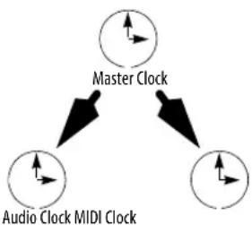
flowchart
graph TD
A["Master Clock"] --> B["Audio Clock MIDI Clock"]
B --> C["Directional Arrow"]
Figure 87-2: Frame-accurate sync.
Frame-accurate sync to blackburst
If you are working with video, you need hardware that can convert video blackburst (a master video timing source)—referred to as house sync—into word clock. The word clock is then passed onto the digital audio hardware.
The MOTU MIDI Timepiece AV synchronizer serves as an excellent, affordable, dependable example of such a device: it has a video input that allows it to resolve to blackburst, while at the same time synchronizing Digital Performer and your word-clock-equipped audio hardware.
Figure 87-3 below shows how a system like this can be configured with a MOTU 24I/O analog audio interface. In this scenario, slave Digital Performer to SMPTE time code as explained in "MTC (MIDI Time Code)" on page 981. Slave the audio interface to its word clock input.

flowchart
graph TD
A["House Sync Generator (video blackburst)"] -->|Blackburst| B["Video Tape Deck (with SMPTE time code on tape)"]
A --> C["Converter Black Burst to Word Clock (e.g. MIDI Timepiece AV)"]
B -->|SMPTE time code| D["SMPTE-to-MIDI converter (e.g. MIDI Timepiece AV)"]
C -->|Word Clock| E["MOTU 24I/O audio interface (or any word clock-equipped audio interface)"]
D -->|MIDI Time Code (MTC)| F["Digital Performer System"]
E --> F
F --> G["MIDI playback engine"]
F --> H["Audio playback engine"]
Figure 87-3: Frame-accurate audio sync using video house sync and word clock.
Frame-accurate sync to SMPTE time code
If you use SMPTE time code as a master sync source (such as LTC recorded on an analog multi-track tape machine), you can use a MOTU MIDI Timepiece AV™ to convert the SMPTE time code into word clock and MIDI Time Code. Figure 87-4 below shows how a system like this is can be configured with a MOTU HD192 analog audio interface. In this scenario, slave Digital Performer to SMPTE time code as explained in “MTC (MIDI Time Code)” on page 981. Slave the audio interface to its word clock input.
SYNC AND THE COMPUTER'S BUILT-IN AUDIO
Digital Performer can play audio tracks via the computer's built-in audio hardware while Digital Performer is slaved to external time code. Setup is done in the usual way as described in "MTC (MIDI Time Code)" on page 981.
However, because the computer's built-in audio hardware has no way of continuously resolving to an external source, Digital Performer has no way to continuously resolve audio tracks to external time code — or the MIDI tracks they are playing along with. MIDI and audio tracks will always start exactly at the correct position when external time code is first received. But after playing for a while, audio tracks may drift out of sync with MIDI tracks.

flowchart
graph TD
A["SMPTE Time Code Source (Multitrack)"] --> B["SMPTE time code (LTC)"]
B --> C["MIDI Timepiece AV™"]
C --> D["Word ClockMIDI Time Code"]
C --> E["SMPTE to MIDI converter"]
C --> F["SMPTE to Word Clock converter"]
C --> G["MOTU HD192 audio interface (or any word clock-equipped audio interface)"]
G --> H["Audio playback engine"]
H --> I["MIDI playback engine"]
I --> J["Digital Performer System"]
J --> K["Word ClockMIDI Time Code"]
Figure 87-4: Frame-accurate audio sync to MIDI Time code.
MIDI tracks, on the other hand, will always remain continuously resolved to the incoming time code. The discrepancy between MIDI and audio tracks is caused by the fact that the audio tracks, after they begin, resolve to the computer's internal timing hardware, not external time code. So, in essence, there are two independent clock sources: external time code and the computer's internal clock. MIDI is slaving to the external time code and audio is slaving to the computer. The inevitable result of two clocks running independently of each other is that they will drift, no matter how accurate they are. Practically speaking, the issue is: how long will it take for them to noticeably drift apart?
When using the computer's built-in audio, the time it takes for MIDI and audio tracks to noticeably drift apart depends on the accuracy of the time code that Digital Performer is slaving to. If you have an extremely accurate time code source, such as a time code generator or other crystal clock-based time code source, you might be able to play MIDI and audio for minutes at a time with no noticeable drift. If, however, the time code being received is not accurate (such as time code from an analog tape deck with its varispeed control adjusted several percent high or low), you might hear drift after only a few measures.
In most situations, you will probably be able to play for at least several minutes without noticeable drift. However, if you are using Digital Performer in a professional situation, we strongly recommend that you invest in a hardware-based digital audio recording system that can be properly and continuously resolved to time code as described earlier in this chapter.
AUDIO SYSTEM CLOCK
If the audio hardware you are using with Digital Performer doesn't support multiple clock sources, the Audio System Clock menu item (Setup menu) will be grayed out. If your audio hardware does
support multiple clock sources, they appear in the Audio System Clock sub-menu. The current clock source is checked; to change it, choose another clock source. Be sure to choose the correct clock source for the situation in which you are running Digital Performer. See your Digital Performer manual for details. Using the proper clock source will prevent clicks, pops, and other undesirable artifacts during digital transfers. It will also ensure that your digital audio is properly resolved with external clock sources, such as SMPTE time code or word clock.

- ABOUT THE MARK OF THE UNICORN LICENSE AGREEMENT AND LIMITED WARRANTY ON SOFTWARE
- REMINDER OF THE TERMS OF YOUR LICENSE
- UPDATE POLICY
- COPYRIGHT NOTICE
- MPEG LICENSE
- Contents at a Glance
- Part 1: Managing Projects
- Part 2: Customizing Your Workspace
- Part 3: Sequences and Tracks
- Part 4: Playing and Recording
- Part 5: Editing
- Part 6: Arranging
- Part 7: Mixing
- Part 8: Processing
- Part 9: Mastering
- Part 10: Synchronization
- Part 11: Appendices
- Contents
- The Digital Performer Project
- Import and Export
- Content Browser
- Audio File Management
- Project File Interchange
- Preferences and Settings
- Commands
- Consolidated Window
- Window Sets
- Sequence Basics
- Track Basics
- Bundles
- MIDI Tracks
- Audio Tracks
- Instrument Tracks
- Aux Tracks and Master Fader Tracks
- Click and Countoff
- MIDI Monitor
- Audio Monitor
- Step Record
- Retrospective MIDI Record
- Clips Window
- POLAR
- Movie Window
- ReWire
- Editing Basics
- Edit Windows
- Tools
- Event List
- Drum Editor
- Notation Editor
- QuickScribe Editor
- Region Menu
- Audio Menu
- Fades and Crossfades
- Takes and Comping
- Tempos and Audio
- Audio Beats and Tempo Detection
- System Exclusive
- Clippings
- Custom Consoles
- Conductor Track
- Change Tempo
- Change Meter
- Change Key
- Insert Measures
- Adjust Beats
- Record Beats
- Markers
- Find Tempo
- Streamers, Punches and Flutters
- Chunks Window
- V-Racks
- Songs
- Mixing Board
- Mix Automation
- Mixing in Surround
- Meter Bridge
- Effects Window
- Audio Effects Processing
- MIDI Effects Processing
- Audio File Conversion
- Time-stretching and pitch-shifting
- Background Processing
- Spectral Effects
- Transposing Audio
- Scale Time
- VocAlign
- Bounce To Disk
- Mastering
- Receive Sync
- Audio Sync
- Transmit Sync
- MIDI Machine Control
- Control Surfaces
- Troubleshooting and Support
- Menus reference
- Part 1
- Managing Projects
- CHAPTER 1 The Digital Performer Project
- OVERVIEW
- COMPONENTS OF A DP PROJECT
- The Project Folder
- Audio Files folder
- Audio Cache folder
- Autosaves folder
- Bounces folder
- Analysis Files folder
- Plug-in Data folder
- Undo folder
- Clippings folder
- CREATING A NEW PROJECT
- CREATING A NEW PROJECT WITH CREATE TRACKS
- CREATING A NEW PROJECT FROM A TEMPLATE
- OPENING AN EXISTING PROJECT
- OPEN RECENT SUB-MENU
- SAVING A PROJECT
- To save a project:
- SAVING A PROJECT FILE UNDER A DIFFERENT NAME
- Click Save.
- SAVE A COPY AS
- USING SAVE A COPY AS FOR INCREMENTAL BACKUPS
- AUTOSAVE
- COLLECTING A PROJECT FOR BACKUP OR TRANSFER
- AVOIDING DISASTER
- IMPORTING FILES IN OTHER FORMATS
- EXPORTING A PROJECT
- MOVING A PROJECT BETWEEN MAC AND WINDOWS
- Moving legacy Mac projects to Windows
- INTERCHANGING WITH FINAL CUT PRO XML
- EXPORTING TO NOTATION SOFTWARE THROUGH MUSICXML
- REVERTING TO A PREVIOUSLY SAVED PROJECT
- CREATING PROJECT TEMPLATES
- Creating a template
- Removing a template file from the sub-menu
- Platform Path
- Creating a default New Template
- LOADING A SEQUENCE, SONG OR V-RACK
- ADDING PROJECT NOTES
- PRINTING PROJECT WINDOWS
- Printing the contents of a list window
- Printing notation
- CLOSING A PROJECT
- Closing a project without saving
- QUITTING/EXITING DIGITAL PERFORMER
- SETTING DIGITAL PERFORMER'S STARTUP PREFERENCES
- HELPFUL PROJECT AND DISK HINTS
- Using the macOS stationery feature (Mac only)
- CHAPTER 2 Import and Export
- IMPORTING PROJECT FILES IN OTHER FORMATS
- Importing/exporting MIDI files via drag and drop
- Importing OMF/AAF files via drag and drop
- Exporting songs
- Exporting to a standard MIDI file
- MIDI File Format options
- File format
- Save track names as plain text
- Expand loops and capture effects
- Exporting to earlier versions of Digital Performer
- Exporting to AudioDesk
- Exporting to OMF or AAF
- EXPORTING SELECTIONS
- Exporting a selection as a MIDI file
- Exporting a selection as a clipping file
- IMPORTING AND EXPORTING AUDIO
- Importing audio with the Import Audio command
- Importing and exporting audio by drag & drop
- Importing an entire audio file
- Loading soundbites from other Digital Performer files
- Converting soundbites that cannot be played
- Audio file formats that can be imported
- Importing REX files
- Importing a REX file into a track
- Viewing REX loop slices and changing their time-stretch attribute
- Acid file and Apple Loop import
- Audio file exporting
- Saving an audio export preset
- BOUNCING AUDIO FILES
- CHAPTER 3 Soundbites Window
- SOUNDBITES WINDOW MINI-MENU
- OPENING THE SOUNDBITES WINDOW
- THE SOUNDBITE LIST
- Showing/hiding columns in the soundbite list
- Rearranging soundbite list columns
- Soundbite list quick reference
- Shortcuts for finding soundbites in the Soundbite list
- View By menu
- Organizing soundbites into folders
- Soundbite source
- Viewing soundbite sources hierarchically with 'By Folder' view
- Dragging soundbites into folders
- Searching the Soundbites list
- SOUNDBITE BASICS
- Generating soundbites while editing
- MONO, STEREO AND MULTI-CHANNEL AUDIO
- SOUNDBITE MANAGEMENT
- Sorting the soundbites list
- Auditioning soundbites with Audible Mode
- Specifying the audio output for auditioning
- Adjusting the volume for auditioning
- Renaming a soundbite
- Lost soundbites
- Finding lost soundbites
- Soundbites that cannot be played
- Selecting unused soundbites
- Deleting soundbites
- Deleting soundbites that are currently being used in a track
- Removing soundbites from the soundbites list without deleting their corresponding region in the audio file
- Deleting the last soundbite in an audio file
- Bypassing warning dialogs when deleting audio files
- Deleting an audio file that contains regions
- Getting rid of unused soundbites after a session
- Compacting audio files
- DRAGGING AND DROPPING SOUNDBITES
- WORKING WITH MULTIPLE SAMPLE FORMATS
- CONVERTING SAMPLE RATE/FORMAT
- AUTOMATIC CONVERSIONS
- RELOAD SOUNDBITE
- REPLACE SOUNDBITE
- EDIT IN WAVEFORM EDITOR
- USE EXTERNAL WAVEFORM EDITOR
- VIEWING MORE SOUND FILE INFORMATION
- CHAPTER 4 Content Browser
- QUICK REFERENCE
- CONTENT BROWSER MINI-MENU
- OPENING THE CONTENT BROWSER
- USING THE CONTENT BROWSER
- AUDITIONING AUDIO CLIPS
- CHAPTER 5 Audio File Management
- THE AUDIO FILES FOLDER
- RENAMING AUDIO FILES
- MOVING AUDIO FILES
- WORKING WITH MULTIPLE DRIVES
- DELETING AUDIO FILES
- GETTING RID OF UNUSED AUDIO
- Selecting and deleting unused soundbites
- Compacting won't work if...
- OR
- COMPACTING AN ENTIRE PROJECT
- CHAPTER 6 Project File Interchange
- INTRODUCTION TO OMF AND AAF
- IMPORTING OMF/AAF FILES
- General recommendations for import
- Guidelines for creating OMF and AAF files for use in Digital Performer
- EXPORTING OMF/AAF FILES
- OMF/AAF export options
- The 'Enforce Compatibility' options
- References existing audio files
- Reference existing audio files exceptions
- Copy all audio files
- Consolidate audio files
- Embed audio data in OMF
- Export audio data as Sound Designer II/AIFF/WAVE files
- 'Export fades as' options
- Exporting 24-bit audio
- Export sample-accurate edits/Quantize edits to frame boundaries
- Export clip-based volume/pan
- Export original timestamps
- Export soundbite names
- Export all sequences
- Export all takes
- OMF/AAF export summary
- General OMF/AAF export recommendations
- Exporting to DAWs
- Exporting to NLEs
- Using embedded audio
- OMF version
- FINAL CUT PRO XML INTERCHANGE
- XML interchange overview
- Import Final Cut Pro 7 XML
- Export Final Cut Pro XML
- Overall workflow
- The Final Cut Pro XML Export Dialog
- Video and audio files
- Conforming path names
- XML version menu
- Include video track
- Export to XML File
- Export directly to Final Cut Pro
- Open Final Cut Pro project
- Show Current DP Sequence
- The Final Cut Pro 7 XML Import Window
- Import from XML File
- Import directly from Final Cut Pro
- Include video
- Include Audio
- Replace sequences
- Add new sequences
- Missing media files
- Comparing imported Final Cut Pro sequences
- Compare Import Source To: XML file
- Viewing comparison results
- Inspecting a change
- Volume and pan information
- Stereo and surround audio
- Part 2
- Customizing Your
- Workspace
- CHAPTER 7 Preferences and Settings
- THE PREFERENCES WINDOW
- Restoring factory default settings
- Reverting
- Closing the Preferences window
- Project File Format and Default File Format
- Wave64
- Audio file defaults
- Audio File Locations
- Copy Audio to Project Folder options
- AUDIO PLUG-INS
- BACKGROUND PROCESSING
- DOCUMENT
- Startup Options
- Recent Documents
- Ask before closing
- Document Templates
- RUN COMMAND WINDOW
- Top Hit Results
- Other results
- SHORTCUTS
- CONSOLIDATED WINDOW
- CONTROL PANEL
- DATA DISPLAY
- Pitch Display
- Tempo Display
- Rectified waveform display
- Audio pitch automation reference
- SCROLLING AND ZOOMING
- Scrolling and Zooming Sensitivity
- Scrolling with Trackpad
- Auto Scroll
- MIDI Auto Zoom
- THEMES
- Selection Color
- Focus Color
- Meter Color
- Clip Color
- Managing theme files
- TRACK COLORS
- The Track Color Preferences
- Use custom track colors
- Assign new tracks options
- Use different colors for different track types:
- Edit Color Schemes
- Use Soundbite Color Bar
- Waveform Colors
- Where track color gets displayed
- Working with color schemes
- Changing the color scheme
- Editing color schemes
- Modifying a color scheme
- Using the Color Picker
- Choosing a track's color
- Assigning colors
- The 'Pick Colors Randomly' option
- Enabling and disabling automatic conversions
- Automatic conversion settings
- On Import
- Whenever File Doesn't Match Project
- Never
- Setting auto conversion options on a per file basis
- CHORD SYMBOLS
- CLIPPINGS
- CONTINUOUS DATA
- EDIT WINDOWS
- Fix partial measures automatically
- Track Selector button
- Edit Window guides
- Default Edit Windows
- INFORMATION BAR
- LYRICS
- MIDI EDITING
- MIDI Editor options
- MIDI Note Display preferences
- Pitch Ruler Settings
- Marquee Selection
- Track Display
- Hide Other Tracks When Opening to
- REGION COMMANDS
- SOUNDBITE LIST
- TOOLS
- Cursor Selection Mode
- Tool Palette Options
- Vertical Tool palette
- Auto Position Tool Palette
- Show in Tool Palette
- TRACKS LIST
- TRACKS OVERVIEW
- Playback and Scrub Wiper
- MIDI Level Meters
- Phrase Settings
- UNDO PRUNING
- WAVEFORM EDITOR
- AUDIO OPTIONS
- Show alert when playback overloads the processor(s)
- Show alert when disk(s) can't keep up with record
- Show alert when available memory is running low
- MultiRecord is always on for audio tracks
- Audio metering is post-pan
- Punch Guard
- Audition volume
- CLICK
- CLICK DEFAULTS
- COUNTOFF
- FILM SCORING EVENTS
- MIDI OPTIONS
- PITCH AND STRETCH
- RECEIVE SYNC
- TRANSMIT SYNC
- TRANSPORT
- Wait button
- When a note is played
- When a note or controller is played
- On any MIDI activity
- Fast Forward/Rewind buttons
- Move playback position by...
- Move playback position continuously
- SCALING ALL WINDOWS UP OR DOWN
- HELP MENU
- Digital Performer Help viewer
- Help Tags
- Checking for updates
- Additional Help menu resources
- CHAPTER 8 Time Formats and Display
- SPECIFICATION OF TIME FORMATS
- Measure time (measure|beat|tick)
- Real time (hours:minutes:seconds.hundredths)
- Frame time (hours:minutes:second:frames)
- Nonstandard frame rates
- Samples
- TIME FORMATS WINDOW
- Customizing the time format display
- Saving time format settings with the project
- Time format keyboard shortcuts
- MIDI display resolution
- trillion PPQ
- Adjustable PPQ display
- PPQ affects data display only
- What PPQ should you use?
- 97
- What's the minimum/maximum PPQ?
- PPQ chart
- SETTING THE START TIME
- CHAPTER 9 Commands
- OPENING THE COMMANDS WINDOW
- NAVIGATING THE COMMANDS WINDOW
- Searching for commands
- Browsing with the list navigation commands
- COMMAND GROUPS
- MIDI MASTERS
- ASSIGNMENTS
- MIDI Assignments
- NUMERIC BASE NOTE
- CHUNK REMOTE ASSIGNMENT
- RUN COMMAND
- EXPORT KEY BINDINGS
- IMPORT KEY BINDINGS
- CHAPTER 10 Consolidated Window
- WINDOW MENU
- Set Focus to Next/Previous Cell: In the
- DECIDING HOW TO WORK WITH WINDOWS
- CONSOLIDATED WINDOW PREFERENCES
- Choosing which windows to display in the Consolidated Window
- Maximum rows to add in the body area
- Maximum rows to add in a sidebar
- Maximum Event Lists to add
- Additional Consolidated Window preferences
- Open Old Documents Using Consolidated
- Open Old Window Sets Using Consolidated
- Close document when Consolidated Window
- Update the Waveform Editor to the Selection:
- OPENING THE CONSOLIDATED WINDOW
- GOING FULL SCREEN
- CONSOLIDATED WINDOW TITLE BAR
- OTHER WINDOW TITLE BARS
- THE CONTROL PANEL
- THE BODY (CENTER) SECTION
- THE SIDEBARS
- Choosing what to display in a sidebar cell
- Resizing the sidebar
- Splitting the sidebar
- Using multiple tabs in one cell
- THE MIXING BOARD
- Mixing Board preference
- USING HORIZONTAL DIVIDERS
- DRAGGING CELLS
- CELL FOCUS
- GETTING RID OF A CELL
- POPPING WINDOWS IN AND OUT
- THE CONSOLIDATED WINDOW AND WINDOW SETS
- Window Set presets
- OPENING OLD DOCUMENTS
- CHAPTER 11 Window Sets
- CREATING A NEW WINDOW SET
- CHOOSING A WINDOW SET
- CHANGING AN EXISTING WINDOW SET
- OTHERWISE MODIFYING WINDOW SETS
- Renaming a window set
- Deleting a window set
- Changing the order of window sets in the menu
- Assigning a keyboard shortcut to a window set
- WINDOW SET TIPS AND TRICKS
- Part 3
- Sequences and
- Tracks
- CHAPTER 12 Sequence Basics
- CHUNK TYPES
- Sequence
- V-Rack
- Song
- MANAGING SEQUENCES, V-RACKS AND SONGS
- CHAPTER 13 Track Basics
- BASIC TRACK TYPES
- MIDI tracks
- Audio tracks
- Instrument tracks
- Aux tracks
- Master Fader tracks
- VCA tracks
- SPECIAL TRACK TYPES
- The Conductor track
- The Movie track
- TRACK SETTINGS
- Name
- The track type icon
- Play/mute
- Solo exemption
- Output assignment
- Take
- Automation settings
- Lock
- Color
- Comment
- CREATING A TRACK
- CREATING SEVERAL TRACKS AT ONCE
- CREATING MULTIPLE TRACK TYPES AT ONCE
- DUPLICATING A TRACK'S SETTINGS
- DUPLICATING A TRACK'S SETTINGS AND DATA
- RENAMING A TRACK
- DELETING A TRACK
- CHAPTER 14 Bundles
- AUDIO BUNDLES
- BUNDLE TYPES
- ADDING AND DELETING BUNDLES
- Creating an audio bundle from assignment menus
- RENAMING BUNDLES
- WORKING WITH TILES ON THE GRID
- EXPORTING AND IMPORTING BUNDLES
- BUNDLE CHANNEL FORMATS
- Audio bundle properties are bound to a hardware driver
- Bundles and panners
- Direct line outputs
- REASSIGNING BUNDLES
- THE INSTRUMENTS TAB
- THE MIDI DEVICES TAB
- Making MIDI connections in the I/O grid
- Devices connected directly with USB, etc.
- Renaming an interface or USB device
- Deleting offline interfaces
- MIDI device properties
- Device
- Properties and ports
- Patches
- CHAPTER 15 MIDI Tracks
- INTEGRATED MIDI AND HARD DISK AUDIO
- MIDI ONLY
- WHAT IS A MIDI TRACK?
- CREATING A MIDI TRACK
- CREATING SEVERAL MIDI TRACKS AT ONCE
- MIDI TRACK SETTINGS
- CHOOSING AN INPUT SOURCE
- CHOOSING A MIDI OUTPUT DESTINATION
- The output destination MIDI device list
- Changing the MIDI device list
- MAKING I/O ASSIGNMENTS FOR MULTIPLE MIDI TRACKS
- MULTIPLE OUTPUT DESTINATIONS
- CREATING A MIDI DEVICE GROUP
- MIDI DRUM & PERCUSSION TRACKS
- REMAP MIDI DEVICES
- CHOOSING A DEFAULT PATCH (SOUND)
- THE PATCH LIST
- THE CURRENT PATCH
- MIDI KEYS
- Playing notes
- Octave up/down
- Octave display
- Note-on velocity
- Pitch Bend
- Mod wheel
- MIDI sustain
- Recording into a MIDI track with MIDI Keys
- Playing a virtual instrument with MIDI Keys
- CHAPTER 16 Audio Tracks
- TYPES OF AUDIO TRACKS
- AUDIO (DISK) TRACKS
- MONO, STEREO, AND SURROUND TRACKS
- CREATING AN AUDIO TRACK
- CREATING SEVERAL AUDIO TRACKS AT ONCE
- AUDIO TRACK SETTINGS
- INPUT SOURCE: AUDIO BUNDLES
- CHOOSING AN AUDIO INPUT AND OUTPUT
- Output assignments
- INPUT MONITOR ENABLE
- STRETCH
- PITCH AND STRETCH CACHE
- ENABLED
- Track Enable button
- MONITORING AN AUDIO TRACK INPUT
- CHANGING AUDIO TRACK SETTINGS ON THE FLY
- MAKING I/O ASSIGNMENTS FOR MULTIPLE TRACKS
- Assigning inputs and outputs
- Skipping master faders
- MANAGING YOUR COMPUTER'S SYSTEM RESOURCES
- Track bouncing with the Bounce command
- FREEZING TRACKS
- Freezing and track mute automation
- CHAPTER 17 Instrument Tracks
- CREATING AN INSTRUMENT TRACK
- VST, AU, and MAS instruments
- Organizing instrument menus
- Unavailable instruments in the sub-menu
- INSTRUMENT TRACK SETTINGS
- WORKING WITH INSTRUMENT PLUG-INS
- INSTRUMENT TRACKS IN THE MIXING BOARD
- OPEN INSTRUMENT SHORTCUT
- INSTRUMENT TRACK AUTOMATION
- FREEZING INSTRUMENT TRACKS
- INSTRUMENTS AS AUDIO PLUG-INS
- INSTRUMENT PLUG-INS IN V-RACKS
- MULTIPLE AUDIO OUTPUTS
- Creating instrument output bundles
- Using instrument output bundles
- DIGITAL PERFORMER'S INCLUDED INSTRUMENTS
- CHAPTER 18 Aux Tracks and Master Fader Tracks
- Using Aux tracks and Songs
- Conserving CPU resources with aux tracks
- Using aux tracks for live inputs such as synthesizers
- Monitoring with Aux tracks present
- Aux track shortcut
- Aux track settings
- Master Fader track settings
- CHAPTER 19 VCA Tracks
- VCA TRACKS AND TRACK GROUPS
- CREATING A VCA TRACK
- VCA track settings
- The VCA track output menu
- Assigning VCA tracks to non-VCA groups
- VCA track level meter
- VCA CONTROL
- Volume fader
- Mute/Solo/Record-enable/Input monitoring
- SHARED TRACKS AND NESTED VCA GROUPS
- VCA TRACKS AND MIX AUTOMATION
- VCA track automation
- VCA volume automation
- VCA track mute automation
- Setting the colors for VCA volume and mute automation
- RELEASING A VCA TRACK FROM ITS GROUP
- MIDI TRACKS AND VCA TRACKS
- EXPORTING TO EARLIER VERSIONS OF DP
- CHAPTER 20 Tracks Window
- TRACKS WINDOW MINI-MENU
- OPENING THE TRACKS WINDOW
- Opening multiple tracks windows
- SEQUENCE MANAGEMENT IN THE TRACKS WINDOW
- Making the Tracks window display a different sequence
- Using the Window Target to switch sequences
- Creating new sequences in the Tracks window
- Renaming and deleting a sequence in the Tracks window
- Making a new, separate sequence based on the current selection
- Opening two or more Tracks windows at once
- THE MARKER MENU
- THE TRACK LIST
- Customizing the Track List
- The input column
- Levels (activity) meters
- Configuring the MIDI activity meters
- Showing MIDI activity or velocity
- Monitoring
- Hiding activity meters to reduce overhead
- Other metering options
- Play-enable button
- The Take column
- Audio track enable/disable
- The track name
- Track color
- The current patch (MIDI tracks only)
- The default patch (MIDI tracks only)
- Automation menu (ATO)
- Stretch (STC)
- Pitch and Stretch Cache (CSH)
- The controller display (CNTRL)
- The comment
- MIDI track device and patch annotations
- WORKING WITH THE TRACK LIST
- Creating a new track
- Creating multiple tracks at once
- Track folders
- Showing and hiding tracks
- Reordering tracks
- Creating and saving track layouts
- Duplicating track layouts
- Duplicating tracks
- Transferring tracks to another sequence
- Selecting tracks
- Selecting tracks for editing
- Deleting tracks
- Opening an edit window for a track
- THE TRACK OVERVIEW
- The time ruler
- Clips
- Audio data
- MIDI data
- Customizing MIDI phrasing blocks
- Dynamic Phrase Parsing
- Break Phrases After \_\_\_\_ Ticks
- Phrase Detail
- Folder contents overview
- Modifier key shortcuts in the Track Overview
- Clicking the time ruler for selecting and cueing
- Temporarily suspending scrolling during playback
- Resuming scrolling
- Scrubbing with the playback wiper
- Nudging with the arrow keys
- Zooming
- Making a selection in the Track Overview
- Working with markers in the Time Ruler
- To accomplish this Do this
- Using the View Filter with the Track Overview
- Track copying and transfer via drag & drop
- CUSTOMIZING THE TRACKS WINDOW
- CHAPTER 21 Track Folders and Track Groups
- Working with track folders
- TRACK GROUPS
- Creating a track group in the Tracks window or Sequence Editor
- Creating a track group in the Mixing Board
- Deleting a track group
- The Track Groups window
- Group types
- Mix group
- Edit group
- Mix & Edit group
- VCA group
- Custom group
- Including a track in several different groups
- Nesting groups within each other
- Temporary track groups
- Temporarily suspending track groups
- Temporarily overriding the group on the fly
- Deleting tracks that belong to a track group
- Track group keyboard shortcuts
- Part 4
- Playing and
- Recording
- CHAPTER 22 Control Panel
- CONTROL PANEL PREFERENCES
- TRANSPORT CONTROLS
- The Play button and playback
- The Rewind button
- The Stop button
- The Pause button
- The Record button and recording
- Overdub Record
- Clip Record
- Undo Record
- Fast/Slow Forward & Rewind
- COUNTER
- Using the Counter to change the current playback location
- Using the decimal key or Command/Ctrl-T to edit SMPTE main counter
- Setting the counter time format
- Playback dashes
- Round on Entry
- Marker counter
- Marker menu
- Using SMPTE timecode bits
- Setting the SMPTE frame rate
- Preserving locked markers when changing the start time
- Creating pickup measures before 1|1|000
- LARGE COUNTER
- Opening the Counter window
- Resizing the Counter window
- Setting the Counter window display
- Counter window mini-menu
- MEMORY BUTTONS
- The Auto-Stop button
- The Auto-Rewind button
- The Memory Cycle button
- Setting the Memory Cycle points graphically in the Memory Cycle strip
- Link Playback to Memory
- Preroll and Postroll
- Punching in and out
- Link Memory to Selection
- Linking playback to the current selection
- AUTO-RECORD
- Setting the punch-in and punch-out points graphically
- Setting the punch-in and punch-out points numerically
- OVERDUB RECORD MODE
- WAIT
- SLAVE TO EXTERNAL SYNC
- SAVING MEMORY AND AUTO-RECORD TIMES
- STATUS STRIP
- The Memory Bar
- The Auto-Record Bar
- The Project and sequence info
- TEMPO CONTROLS
- The Tempo Control menu
- Tempo slid er
- The Tap Pad
- Conductor Track
- Remote control of the tempo
- Tap to Enter Tempo
- Tapping to enter a tempo in a text box
- Canceling tempo entry
- The current meter display
- The beat value
- The current tempo
- Displaying and typing in frame-click tempos
- Tempo Control during external synchronization
- AUDIBLE MODE
- SOLO MODE
- PRIMARY AND ALTERNATE TOOLS
- Displaying the full tool palette
- KEYPAD SHORTCUTS
- DISPLAY PREFERENCES
- CHAPTER 23 Playback
- MIDI PLAYBACK BASICS
- AUDIO PLAYBACK BASICS
- HOW TO PLAY A SEQUENCE OR SONG
- MONITORING LEVELS
- EDITING DURING PLAYBACK
- SCREEN RE-DISPLAY
- MUTING AND UNMUTING TRACKS DURING PLAYBACK
- SOLOING TRACKS
- 'PARTIAL-SOLO'
- Partial solo percentage
- The 'Solo front-most edit window' option
- Disabling 'Partial Solo' mode
- LOOPING PLAYBACK
- PLAYING THE CURRENT SELECTION
- EVENT CHASING
- Enabling event chasing
- Inserting initial events in MIDI tracks
- Omitting initial controllers in MIDI tracks
- Forward chasing
- Event chasing and audio track editing
- Event chasing in songs
- All windows versus the top window
- Paging versus continuous scrolling
- Paging
- Continuous Scroll
- Enabling Auto Scroll by window type
- Displaying the playback wiper
- Cueing with the wiper
- Zooming with the wiper
- Auto Scrolling with multiple sequences or songs
- Suspending Auto Scrolling
- Disabling Auto Scrolling
- SCRUBBING MULTIPLE MIDI TRACKS
- SCRUBBING AND GRID SNAPPING
- SCRUBBING AUDIO
- SLOW AND FAST FORWARDING
- STOP SOUNDING MIDI DEVICES (PANIC)
- CHAPTER 24 Recording
- CHOOSING A SEQUENCE TO RECORD INTO
- SETTING TEMPO AND METER
- Setting the tempo
- Programming a meter map
- Recording at a slower tempo
- RECORDING TO A CLICK
- RECORDING WITH A COUNTOFF
- INPUT FILTER
- Specifying controller numbers
- The 'Input from MMC Devices' option
- INPUT QUANTIZE
- Opening the Input Quantize Window
- Turning Input Quantize on and off
- Setting the Input Quantize options
- Changing options during recording
- Retrospective MIDI Record
- NON-DESTRUCTIVE OUTPUT QUANTIZE
- PREPARING A MIDI TRACK FOR RECORDING
- PREPARING AN AUDIO TRACK FOR RECORDING
- MIDI INPUT MONITORING
- Turning on MIDI Patch Thru
- Direct echo
- Auto channelize
- Auto channelizing in a sequence
- Auto channelizing with Multi Record turned on
- Auto channelizing with MIDI effects plug-ins
- Auto channelizing in a song
- Auto channelizing and the Input Filter
- Patching thru in the background
- MIDI beat clocks and MIDI Patch Thru
- MIDI patch thru via a MIDI interface
- Sync Recorded MIDI to Patch Thru
- Patch Thru in Background
- AUDIO INPUT MONITORING
- The input monitor button
- The record button
- Input monitoring modes (Audio Patch Thru)
- Monitoring input levels
- Monitoring outside of Digital Performer
- Applying real-time audio effects plug-ins to live audio input
- Audio monitoring latency
- Hardware monitoring versus monitoring with effects
- Setting the input monitoring mode
- Direct hardware playthrough
- Monitor record-enabled tracks through effects
- USING THE WAIT AND COUNTOFF FEATURES
- START RECORDING
- Display update during recording
- Record-enabling audio tracks on the fly
- STOP RECORDING
- HOW AUDIO IS RECORDED ON DISK
- RECORDING SEVERAL MIDI TRACKS IN ONE PASS
- Changing Multi Record on the fly
- RECORDING SEVERAL AUDIO TRACKS IN ONE PASS
- RECORDING AUDIO AND MIDI AT THE SAME TIME
- MANUAL PUNCH-IN/PUNCH-OUT ON THE FLY
- AUTOMATIC PUNCH-IN/PUNCH-OUT
- Punch-in recording in MIDI tracks
- OVERDUB RECORDING
- MIDI overdub recording
- Overdub recording and MIDI controller data
- Audio overdub recording
- Overdub recording and the Conductor Track
- Record With Overdub On or Off
- RECORDING MULTIPLE TAKES
- CYCLE-RECORDING
- Setting up for cycle-recording
- Cycle-recording in MIDI tracks
- Editing newly recorded MIDI data
- Spot Erasing from your MIDI controller
- Cycle-recording in audio tracks
- Capturing the perfect take
- Audio cycle-recording in the POLAR window
- Creating a permanent loop
- STEP RECORDING
- RECORDING IN EXTERNAL SYNC
- Recording while still-framed
- SAMPLE FORMAT
- Choosing the sample format
- GETTING AN ERROR MESSAGE
- CHAPTER 25 Click and Countoff
- Enabling the click
- CLICK PREFERENCES
- Type of dick
- Audio click
- Audio output
- Click sounds
- Audio click volume control
- Adding your own click sounds
- Disabling the audio click
- MIDI Click
- Data for MIDI click
- Visual Punches
- Click options
- Audition Click
- Master click volume
- Waveform Editor Beat Click
- The default click list
- Default click settings
- Saving a customized click
- Selecting a default click panel
- The counter runs during countoff
- The movie window and countoff
- Indefinite countoff
- COUNTOFF PREFERENCES
- Specifying an audio click during the countoff
- Follow Conductor
- Beat Value
- Default for Meter
- Pattern
- Saved pattern clicks
- Countoff length
- Countoff only when recording
- Visual countoff
- Punches in sync with click
- Warning streamer before countoff
- Warning streamer at end of countoff
- CHAPTER 26 MIDI Monitor
- OPENING THE MIDI MONITOR WINDOW
- BASICS
- CHAPTER 27 Audio Monitor
- AUDIO MONITOR QUICK REFERENCE
- Input (IN)
- Level meters
- Takefiles
- Available record time
- Take Folder
- MINI-MENU QUICK REFERENCE
- BUSES IN THE AUDIO MONITOR
- VIRTUAL INSTRUMENT INPUTS
- NAMING A TAKEFILE BEFORE RECORDING
- Changing the takefile location for several (or all) inputs once
- Organizing audio files into folders as you go
- Checking the current takefile location
- Remembering takefile locations
- ADJUSTING THE LEVEL METER RANGE
- Using the clip indicator to avoid clipping
- Retain clip
- Clearing the clip indicators
- Scrolling to the record-enabled inputs
- SETTING THE INPUT LEVEL
- OTHER WAYS TO MONITOR INPUT LEVELS
- CHAPTER 28 Step Record
- Step record mini-menu
- Step recording notes and rests
- GETTING READY
- Setting step durations
- Setting dotted durations
- Entering a tuplet duration
- Specifying an exact number of ticks for a step
- Choosing a note duration
- Generating random note durations within a range
- Setting default step-record durations
- Choosing a note offset
- Generating random note offsets within a range
- Soloing the record track
- PERFORMING STEP ENTRY
- Stepping automatically
- Stepping manually
- Entering rests
- Hearing a click after each step
- Listening to what you have recorded
- Disconnecting the counter from step record
- Connecting the main counter to step record
- Changing the current step location
- Displaying notes as you step enter
- Erasing the last step with the backstep button
- Stepping to the next beat or measure
- Changing the current record track
- Adding to existing material in a track
- Step recording controllers, patch changes, or pitch bend
- STEP RECORDING DURING PLAYBACK
- STEP RECORD SHORTCUTS
- Controlling duration with a MIDI controller
- Controlling the offset with a MIDI controller
- Using the numeric keypad
- BE CAREFUL
- HINTS
- CHAPTER 29 Retrospective MIDI Record
- MIDI INPUT IS ALWAYS BEING CAPTURED
- INSERTING CAPTURED MATERIAL INTO A MIDI TRACK
- Choosing a MIDI track
- Specifying a location
- Inserting into MIDI clips
- Inserting into an empty sequence
- Inserting into a sequence with existing material
- Preserving detected tempo
- Overdub mode
- RETROSPECTIVE MIDI RECORD IN THE CLIPS WINDOW
- RETROSPECTIVE MIDI RECORD AND MULTI-RECORD
- RETROSPECTIVE MIDI RECORD AND INPUT QUANTIZE
- RETROSPECTIVE MIDI RECORD AND UNDO
- CHAPTER 30 Clips Window
- CLIPS WINDOW MINI-MENU
- WHAT IS A CLIP?
- CLIPS VERSUS CLIPPINGS
- OPENING THE CLIPS WINDOW
- CLIPS WINDOW BASICS
- THE TRACK STRETCH SETTING
- SHOWING, HIDING AND ARRANGING TRACK COLUMNS
- TRACK TYPES
- TRACK PLAYBACK VERSUS CLIP PLAYBACK
- CREATING CLIPS
- Drag and drop
- Copy and paste
- Create a new, empty clip
- Record into an empty clip
- Record into an existing clip
- THE TRIGGER BUTTON
- TRACK CLIPS
- CLIP MENU
- SCENES
- THE TRACK SCENE
- PLAYING CLIPS AND SCENES
- THE MULTI-QUEUE
- If... Then...
- MIXER CHANNELS
- THE CLIP EDITOR
- Clip settings
- MIDI binding
- Link Clip to Scene
- Start
- Loop (versus one-shot)
- Loop Start time/End/Duration
- Meter
- Clip Editor
- CLIP RECORD MODE
- Recording triggered clips to tracks
- MIDI LEARN MODE
- Making assignments
- Learn channel/source
- CHAPTER 31 POLAR
- A TYPICAL POLAR SESSION
- RAM-based loop recording
- Recording in context
- Saving your POLAR session
- IDEAS FOR USING POLAR
- PREPARATIONS FOR USING POLAR
- Listening to existing audio and MIDI tracks while recording in POLAR
- Establishing a tempo reference
- Recording without a tempo reference
- OPENING THE POLAR WINDOW
- MEMORY USED
- WAYS TO FREE UP RAM FOR POLAR RECORDING
- SETTING THE LENGTH OF EACH PASS
- Getting creative with passes of different lengths
- Setting the length of the first pass
- CHOOSING AN INPUT AND SETTING INPUT LEVEL
- PROCESSING POLAR INPUT WITH EFFECTS
- RECORDING MULTIPLE CHANNELS INTO POLAR
- CHOOSING AN OUTPUT
- CONTROLLING POLAR'S OUTPUT VOLUME
- EFFECTS PROCESSING ON OUTPUT
- MONITORING POLAR'S LIVE AUDIO INPUT
- THE CURRENT PASS
- ADJUSTING LEVELS AND PANNING
- PLAYBACK AND TRANSPORT CONTROL
- CREATING NEW PASSES
- Automatically muting the previous pass
- VIEWING PREVIOUS PASSES
- WORKING WITH PASSES IN THE PASS LIST
- WORKING WITH PASS GROUPS
- EXPORTING A POLAR SESSION
- POLAR Export Options
- SAVING AND LOADING POLAR SESSIONS
- REMOTE CONTROL OF THE POLAR WINDOW
- CHAPTER 32 Movie Window
- RANDOM ACCESS DIGITAL PICTURE
- SUPPORTED VIDEO FORMATS
- OPENING MOVIES
- Working with multiple sequences
- Displaying a blank movie for visual cues
- CLOSING MOVIES
- MOVIE CONTROL BAR
- Volume
- Play/Stop
- Full screen
- Time elapsed/remaining
- Scroll bar
- Frame backward/forward
- Window resizing
- Popping in and out of the Consolidated Window
- MOVIE WINDOW MINI-MENU COMMANDS
- SCRUBBING THE MOVIE WINDOW
- IMPROVING MOVIE WINDOW PERFORMANCE
- EXTERNAL VIDEO HARDWARE OUTPUT
- MOTU video interfaces
- Third-party video hardware
- Enabling external video hardware output
- Choosing a video format
- Turning off external video output
- External video playback offset
- Choosing an offset
- Creating offset presets
- FireWire video converters
- Enabling FireWire video output
- FireWire video output does not support audio
- FireWire video playback offset
- STREAMERS AND OTHER VISUAL CUES
- EXPORTING A MOVIE
- CHAPTER 33 ReWire
- WHAT IS REWIRE?
- Re Wire
- SETTING UP REWIRE
- MIDI OUTPUT
- Publishing ReWire device MIDI inputs/outputs to other Core MIDI software (macOS only)
- MULTIPLE REWIRE AUDIO OUTPUTS
- SYNCHRONIZATION AND TRANSPORT CONTROL
- TEMPO CONTROL
- PLUG-IN PROCESSING ON REWIRE SYNTH INPUTS
- RENAMING REWIRE SYNTH INPUTS
- QUITTING THE REWIRE SYNTH
- Part 5
- Editing
- CHAPTER 34 Editing Basics
- UNLIMITED UNDO/REDO
- SELECTING AND SEARCHING
- REGION EDITING
- Selecting regions
- Applying Edit and Region menu operations
- Region menu exceptions for audio
- VIEW MENU
- Show/Hide Tracks
- Show Tracks
- Show Only Tracks
- Hide Tracks
- Track Layouts
- Show Only
- Show/Hide Lanes
- Grid
- Colors
- VIEW FILTER
- Global View Filter vs. Event List View Filter
- Always be aware of the View Filter settings
- Specifying controller numbers and automation types in the View Filter
- The View Filter window mini-menu
- Saving View Filter settings
- Recalling saved settings
- The Event List View Filter
- View filter example: removing a specific type of data from a track
- Zoom buttons
- Zooming quickly by pressing
- Wiper zooming
- Zooming with the scroll wheel
- Zooming with a track pad
- Keyboard zooming shortcuts
- Zoom menu shortcuts
- Zoom in/out
- Zoom To Default Zoom
- Zoom to Selected Time Range
- Zoom to Selection
- Zoom to Track
- Zoom Back and Zoom Forward
- Auto Zoom Track
- Working with the zoom settings
- Switching among 2 or 3 zoom settings
- Zoom tool
- Zoom history and Zoom Forward/Backward
- Zooming, Edit Resolution and nudging
- SCROLL TO
- GRAPHIC EDITING TECHNIQUES
- Shift-drag to constrain
- Option/Alt-drag to duplicate
- Canceling while dragging
- Shift-clicking to select non-adjacent events
- Other selection techniques
- Dragging multiple data types
- Nudging
- Using Edit Resolution
- Using Undo
- AUDIO EDITING BASICS
- Non-destructive, destructive and constructive audio editing
- Non-destructive Edit menu and Region menu editing
- Destructive editing in the Waveform Editor
- You can't mix audio and MIDI in the same track
- Editing audio and MIDI data simultaneously
- Editing soundbites in the Event List
- Editing soundbites in the Sequence Editor
- Editing clips
- SAMPLE ACCURATE EDITING
- The Samples time format
- Zooming in to the sample level for editing, trimming, nudging, etc. by sample
- Enabling audible mode
- Playing individual MIDI notes
- Playing individual soundbites
- Specifying audio output for auditioning
- Playing phrases
- Playing MIDI chords
- Playing MIDI data other than notes
- CHAPTER 35 Edit Windows
- EDIT WINDOW OVERVIEW
- The Tracks window
- Sequence Editor
- The Event List
- MIDI Editor
- Drum Editor
- Notation Editor
- QuickScribe Editor
- EDIT WINDOWS BY TRACK TYPE
- OPENING EDIT WINDOWS
- VIEWING MULTIPLE TRACKS IN ONE EDIT WINDOW
- Editors that display only one track at a time
- Editors that display one or more tracks
- Exceptions
- The track selector list
- Track folders in the track selector
- The track selector list and soloing
- Master track selector
- Track Selector
- VIEWING THE SAME TRACK IN MULTIPLE EDIT WINDOWS
- WINDOW TARGET
- Switching to a different track
- Switching to a different sequence
- EDIT WINDOW MINI-MENUS
- Scroll To Counter
- Reinsert
- Other editors
- INFORMATION WINDOWS
- LEGEND
- Changing icon colors
- RELATED TOPICS FOR EDITOR WINDOWS
- Scrolling during playback
- Selecting data in edit windows
- Showing and hiding data with the View Filter
- CHAPTER 36 Tools
- MAIN AND ALTERNATE TOOLS
- ROTATING THE TOOL PALETTE
- PALETTE DOCKING
- CLOSING THE TOOL PALETTE
- KEYBOARD SHORTCUTS FOR TOOLS
- Tool shortcuts can be "sticky"
- Cycling tools
- POINTER TOOL
- I-BEAM TOOL
- Selecting soundbites with the I-Beam tool
- Selecting MIDI notes with the I-Beam tool
- I-Beam cursor
- Getting an insertion point in an event list
- PENCIL TOOL
- The Pencil tool settings in the Drum Editor
- INSERT/RESHAPE CURVE
- RESHAPE TOOL
- Using the Reshape tool in the Drum Editor note grid
- RESHAPE MODE MENU
- RHYTHM BRUSH
- Zoom tool shortcuts
- MUTE TOOL
- SCISSORS TOOL
- TRIM TOOL
- Soundbites
- Scaling continuous data
- Flattening continuous data
- ROLL TOOL
- SLIP TOOL
- SLIDE TOOL
- COMP TOOL
- VELOCITY TOOL
- HAND TOOL
- CHAPTER 37 Information Windows
- SNAP INFORMATION
- Snap to Grid
- Auto mode
- Fixed mode
- Using Snap to Grid
- Setting the Edit Grid Resolution
- Triplet and dotted triplet grid editing
- Edit grid supports all time formats
- Snap to Grid and selecting
- Temporarily overriding Snap to Grid
- Don't let the edit grid fool you
- Displaying edit grid lines
- Snap to Beat
- Snap to Markers
- Snap Relative
- Nudge
- CURSOR INFORMATION
- Time
- Value
- Cursor Info in the Waveform Editor
- Customizing the cursor coordinates display
- EVENT INFORMATION
- SELECTION INFORMATION
- Editing the selection bar numbers directly
- Using the Set To menu shortcuts
- Clicking the start and end buttons
- The selection bar shortcuts
- The "Remember Times" command
- Load Selection
- Making a selection in an edit window
- Smart Selections
- TRACK INSPECTOR
- CHANNEL STRIP
- Locking the Channel Strip window
- Displaying the Channel Strip in the Information Bar
- Small menus
- Track Selector button preferences
- SOUND FILE INFORMATION
- Choosing an audio file, soundbite or loop
- The Sound File section
- Soundbite preferences for transposing and time-stretching
- Transpose preference
- Time scale versus don't time scale
- Setting sound file prefs for multiple soundbites
- The Soundbite section
- The Audio Loop section
- Information Bar settings
- Showing/hiding the Information Bar
- Configuring the Information Bar
- Using two lines for the Information Bar
- Opening the Information windows
- Additionally:
- CHAPTER 38 Sequence Editor
- TOOL PALETTE QUICK REFERENCE
- SEQUENCE EDITOR MINI-MENU
- SEQUENCE EDITOR TITLE BAR
- SEQUENCE EDITOR BASICS
- OPENING THE SEQUENCE EDITOR
- SWITCHING SEQUENCES
- SEQUENCE MANAGEMENT
- TRACK MANAGEMENT
- The Track Selector
- Moving tracks up or down
- Adding, duplicating and deleting tracks
- Making audio track input/output assignments
- Opening other edit windows from the Sequence Editor
- SNAP, CURSOR, SELECTION, AND EVENT INFORMATION
- THE MARKER STRIP
- Markers
- Showing marker grid lines
- Making a time-range selection with markers
- Editing markers
- Meter and key changes
- ZOOMING TECHNIQUES
- Zoom shortcuts
- Track names
- Track type icon/color selector
- Locked tracks display a line under their name
- The Edit Layer
- Choosing the edit layer for all tracks at once
- Shortcuts for changing the edit layer
- Hiding background layers
- Using lanes instead of edit layers
- Using edit layers
- Level meter
- Track settings menu
- View Mode
- The spectrogram display
- Waveform/note grid vertical zoom
- Insert menu
- MIDI track settings menu
- Note grid vertical zoom
- Note grid scroll bar
- WORKING WITH MIDI TRACKS
- RESIZING TRACKS
- Shortcuts for vertical track resizing
- Resizing the track info panel
- EFFECT INSERTS PANEL
- Working with waveforms
- Stereo versus mono waveforms
- Surround waveforms
- Soundbites are clones
- Graphic editing is nondestructive
- Soundbites that cannot play
- Viewing Sequence Editor soundbites in the Soundbites window
- Reveal In Finder/Show in Explorer command
- INSERTING SOUNDDBITES
- Dragging and dropping audio into the Sequence Editor
- Using the Insert Audio command
- Building a playlist
- Changing a soundbite name
- Replacing a soundbite with another
- MOVING SOUNDBITES
- Moving soundbites vertically from one track to another
- Constraining dragging operations
- Moving multiple soundbites at the same time
- Snapping to the edit grid
- Nudging soundbites with the arrow keys
- "Throwing" soundbites to the next or previous soundbite
- Option/Alt-dragging to make a copy
- Option/Alt-Control/Win-dragging to copy soundbites & place them end to end
- Creating a stutter effect
- MUTING AND UNMUTING SOUNDDBITES
- Inserting mute automation
- Using the Mute tool
- BITE GAIN
- OVERLAPPING AND LAYERING SOUNDBITES
- TRIMMING (EDGE EDITING) SOUNDBITES
- The Pointer, Trim, Roll, Slip and Slide tools
- Affecting all copies of a soundbite versus one copy
- Option/Alt-dragging to override Edge Edit Copy
- Edge editing multiple soundbites
- Edge editing when soundbites overlap
- Using the edit grid when edge editing
- Scrubbing while trimming soundbites
- Using Slip, Slide and Roll on multiple soundbites
- GRAPHIC TIME STRETCHING OF AUDIO
- APPLYING FADES AND CROSSFADES
- TAKES
- SELECTION TECHNIQUES
- Selecting a time range in the time ruler over one or more tracks
- Pasting into a time ruler selection
- Scrubbing audio inside a popped-up soundbite
- Controlling scrubbing speed
- Scrubbing while selecting
- Adjusting the volume for scrubbing
- Using the Search command to select data
- Editing selected audio data
- SHOW TIMES
- Current Time
- Original Timestamp
- User Timestamp
- SYNC POINTS
- Creating a sync point
- Setting a sync point at the first beat
- Importing sync points
- Resetting sync points
- Moving a sync point
- Time-stretching and sync points
- Sync points in the Waveform Editor
- Sync points and setting the meter for soundbite
- WORKING WITH CLIPS
- Clip basics
- The Clip edit layer
- Creating a clip
- Recording MIDI into track clips
- Packing track data into clips
- Unpacking clips
- Clip layering
- Edge-editing a clip
- Looping a clip
- Muting/unmuting clips
- Other clip editing techniques
- Opening the Clip Editor
- WORKING WITH BREAKPOINT MIX AUTOMATION
- Choosing the active data layer
- Displaying automation lanes
- Zooming for a better resolution
- Inserting mix automation data
- To do this: Do this:
- Constraining a periodic waveform to beats
- Using modifier keys to control period, phase, and other waveform parameters
- Using the spline curve
- Reshaping an existing curve
- Selecting mix automation data control points
- Dragging control points
- Selecting multiple data types at one time
- Selecting control points with soundbites (or MIDI notes)
- Removing control points
- Cutting, copying, and pasting control points
- Disabling automation temporarily
- SOUNDBITE VOLUME AUTOMATION
- Accessing bite volume automation
- Working with soundbite volume automation
- WORKING WITH EVENT FLAGS
- THE VIEW FILTER
- SCRUBBING IN THE SEQUENCE EDITOR
- CHAPTER 39 MIDI Editor
- MIDI EDITOR MINI-MENU
- MIDI EDITOR TITLE BAR
- MIDI EDITOR BASICS
- OPENING THE MIDI EDITOR
- THE MASTER TRACK SELECTOR
- OPENING A SEPARATE MIDI EDITOR FOR EACH TRACK
- SWITCHING TRACKS WITH THE WINDOW TARGET MENU
- Cursor tracking
- Choosing time formats
- Zooming the Time Ruler
- Using the Time Ruler to cue playback
- Using the Time Ruler to select a time range
- THE NOTE GRID
- Note Grid basics
- Scrolling in the Note Grid
- Controlling the dimensions of the Note Grid
- Viewing notes that are out of view
- Displaying notes
- The View Filter and the Note Grid
- THE PITCH RULER
- Listening to the Pitch Ruler
- Zooming the Pitch Ruler
- INSERTING NOTES
- Inserting two or more notes of equal duration
- Erasing notes with the Pencil
- Inserting a note using a MIDI controller
- Inserting a chord with a MIDI controller
- SELECTING NOTES
- Selecting a note
- Selecting a group of notes
- Using the Shift key to extend selections
- Selecting all notes of the same pitch
- EDITING NOTES
- Changing a note's pitch or location
- Nudging notes with the Left Arrow and Right Arrow keys
- Changing a note's duration
- Changing a note's pitch using a MIDI controller
- Editing a group of notes
- Changing two or more notes to the same pitch
- Hearing notes when editing them
- Temporarily muting notes
- THE CONTINUOUS DATA GRID
- Continuous data grid basics
- The grid displays the master track only
- Adjusting the grid height with the Median Strip
- Zooming the Continuous Data Grid
- THREE CONTINUOUS DATA DISPLAY MODES
- Points
- Bars
- Lines
- THE CONTINUOUS DATA RULER
- SHOWING/HIDING CONTINUOUS DATA TYPES
- The 'Show only' Filter
- The Insert menu filter
- The Pitch Bend ruler
- CONT. DATA ICONS
- CHANGING CONTINUOUS DATA COLORS
- Clearing a continuous data color
- Reverting to a default color
- NOTE VELOCITIES
- On-velocity tails
- Hiding velocities
- EDITING CONTINUOUS DATA IN POINTS OR BARS MODE
- Inserting continuous data in Points or Bars mode
- Selecting continuous data in Points or Bars mode
- Dragging events in Points or Bars mode
- Scaling by dragging
- Editing the value of an event using a MIDI controller in Points or Bars mode
- Reshaping data curves
- EDITING CONTINUOUS DATA IN LINES MODE
- MIDI data versus audio ramps
- Points, stair-steps and ramps
- Ramps
- Steps
- Ramp density
- To achieve this: Do this:
- Working with Lines Mode
- Region operations in Lines Mode
- THE MEDIAN STRIP
- Moving the Median Strip
- Working with discrete MIDI events in the Median Strip
- Inserting an event in the Median Strip
- Editing an Event in the Median Strip
- Note grid zooming
- SCRUBBING IN THE MIDI EDITOR
- EDITING IN THE CONDUCTOR TRACK
- The Conductor Track Median Strip
- Inserting a meter/key change
- Working with markers
- Editing the location of a meter change, key change, or marker
- The Tempo Change Grid
- Inserting tempo changes
- Getting Digital Performer to follow tempo changes
- Zooming the Tempo Ruler
- CLIPS IN THE MIDI EDITOR
- CHAPTER 40 Event List
- EVENT LIST MINI-MENU
- EVENT LIST TITLE BAR
- EVENT LIST BASICS
- Showing/hiding durations, end times and sync points
- Showing/hiding types of data
- TYPES OF EVENTS
- Notes
- Patch change
- Song change
- Mono key pressure
- Poly key pressure
- Controllers
- System exclusive
- Tune request
- Mode changes
- Omni mode
- Poly mode ("Mode 3")
- Mono mode ("Mode 4")
- Multi mode (Omni off)
- Local control
- All Notes Off
- Soundbite location
- Soundbite duration
- Soundbite end time
- Soundbite name
- Inserting a soundbite in the Event List
- Soundbite sync points
- Soundbite layering
- Audio volume and pan events
- Audio volume events
- Audio pan events
- MIX AUTOMATION DATA
- Plug-in parameter automation
- Mute automation
- Send level and mute automation
- CLIPS AND CONDUCTOR TRACK DATA
- Meter changes
- Tempo changes
- Key changes
- Eb Major
- INSERTING DATA IN THE EVENT LIST
- Inserting an event using the insertion cursor
- Inserting multiple events of the same type
- EDITING DATA IN THE EVENT LIST
- Selecting data in the Event List
- Choosing an insertion point for pasting
- Dragging soundbites into the Event List
- Editing individual events
- Changing event values by dragging
- Changing the name of a soundbite
- Replacing a soundbite with another soundbite
- EVENT LIST HINTS
- Finding patch numbers
- Inserting multiple events with Repeat
- CHAPTER 41 Drum Editor
- DRUM EDITOR MINI-MENU
- DRUM EDITOR BASICS
- OPENING THE DRUM EDITOR
- THE DRUM EDITOR TITLE BAR
- USING THE WINDOW TARGET MENU
- THE FOUR DRUM EDITOR PANES
- THE NOTE LIST
- Each pitch represents a drum instrument
- Parent MIDI tracks
- Move handle
- Record button
- Play button
- Track name
- Playback device
- Default patch/drum kit
- Parent track selecting/highlighting
- Working with the note list
- Pitch (instrument)
- Quantize
- Adjusting quantize settings
- Offset
- Viewing only the notes you're working with
- Always Show All Notes
- Adding instruments to the list
- Drum Editor drum kit presets
- Saving, renaming and deleting drum kits
- Hiding notes
- Showing notes that are currently hidden
- Working with note names
- Working with factory-supplied note name lists
- Working with pitched percussion
- View resolution
- The Memory Cycle strip
- The Auto Record strip
- The playback locator
- The four display modes
- Display mode selection shortcuts
- Grid with Velocity
- Velocity and Duration
- Free
- Resizing each row
- Resizing shortcuts
- Working with triplets, tuples and non-grid based rhythms
- Working with multiple tracks
- Inserting notes and continuous data with the Pencil tool
- USING THE TOOL PALETTE IN THE DRUM EDITOR
- The Pencil settings
- The Reshape tool
- The Rhythm Brush tool
- Using the Rhythm Brush
- The preset menu
- Using custom rhythmic patterns
- Creating custom patterns
- Deleting patterns
- Using a fixed value
- The 'Use Alternating strokes' option
- Loop tool
- NOTE GROUPS
- Adding notes to a group
- SCRUBBING IN THE DRUM EDITOR
- CHAPTER 42 Notation Editor
- NOTATION EDITOR QUICK REFERENCE
- NOTATION EDITOR MINI-MENU
- NOTATION EDITOR BASICS
- OPENING THE NOTATION EDITOR
- THE NOTATION EDITOR TITLE BAR
- DISPLAY RESOLUTION
- Display resolution affects display only
- OCTAVE UP/DOWN BUTTONS
- INSERTING, SELECTING & EDITING NOTES
- Selecting notes for editing
- Dragging Notes
- Editing Durations
- SCRUBBING IN THE NOTATION EDITOR
- ZOOMING IN THE NOTATION EDITOR
- CHAPTER 43 QuickScribe Editor
- QUICKSCRIBE EDITOR MINI-MENU
- Consolidate Rests / Unconsolidate Rests:
- QUICKSCRIBE EDITOR BASICS
- Virtual paper
- OPENING THE QUICKSCRIBE EDITOR
- THE QUICKSCRIBE EDITOR TITLE BAR
- THE QUICKSCRIBE TRANSCRIPTION ENGINE
- Floating split points and multiple voices
- Displaying triplets and tuplets
- Context sensitive note spelling
- THE PLAYBACK WIPER
- GETTING AROUND IN THE QUICKSCRIBE EDITOR
- Mouse wheel scrolling
- QuickScribe commands
- QUICKSCRIBE OPTIONS MENU
- Separate QuickScribe options for three different QuickScribe views
- SCORE OPTIONS
- Creating a title page
- Full part names/Abbreviated part names
- Adjusting the space between staves and staff systems
- Show tempo marking above first measure
- System Bracket/Grand Staff Brace options
- Show rests in empty measures
- Showing/hiding time-anchored text
- Transcription
- TRACK OPTIONS
- Track menu
- Use Default
- Type of staff (and clef)
- Single staff
- Grand staff
- Use single staff unless it requires more than \_\_\_\_ ledgers
- Track name abbreviation
- Transposition
- Inter-staff spacing
- MARKER OPTIONS
- Displaying marker location
- Cascading overlapping markers
- Hiding markers in a dense score
- Setting marker font, size, and style
- MEASURE NUMBERS
- Measure number text formatting
- MEASURE SPACING
- Space measures \_\_\_\_ per line
- Space measures automatically
- SET SCORE LENGTH
- Linear Score
- Non-linear (Arranged) Score
- CONTROLLING PAGE SIZE
- ADJUSTING SYSTEM MARGINS
- THE QUICKSCRIBE TOOL PALETTE
- Braces, brackets and barlines
- WORKING WITH NOTES
- Rests are automatic
- Inserting notes with the mouse
- Inserting notes with the computer keyboard
- Selecting durations with the extended keypad
- Hearing notes while inserting them with the mouse
- Step Recording notes with a MIDI controller To insert notes with a MIDI controller:
- Getting the pointer temporarily
- Dragging selected notes
- Drag and drop from the QuickScribe Editor
- Cutting, copying & pasting notes
- Using Region menu commands
- Changing note durations
- Automatic vs. Manual durations
- Controlling note spellings
- Changing how an accidental is spelled
- Moving a note into the left or right hand on a grand staff
- Changing the size of a notehead
- Entering chord symbols
- Transposing chord symbols
- Chord symbols in the Event List
- Hiding chord symbols
- Chord symbols preferences
- Text style
- Tab key advances
- Apply To Score
- Setting preferences from existing chord symbol
- Setting preferences on-the-fly
- INSERTING A STAFF BRACE OR BRACKET
- THE DYNAMICS PALETTE
- Dynamic symbol placement
- Working with dynamic symbols
- Adjusting a hairpin crescendo/decrescendo
- Closing the Dynamics Palette
- POPUP METER CHANGES, KEY CHANGES AND TEMPOS
- Popup Key Changes
- Popup Tempo Changes
- WORKING WITH TEXT
- Inserting text
- Choosing where to display text
- Time-Anchored Text
- On These Parts Only
- On Single Part Only
- Making titles, headers and footers
- Making page numbers
- Displaying the current date
- Selecting text
- Moving page text
- Typing and editing text inside a text box
- Pasting text into Digital Performer from other programs
- Changing text attributes
- Installing fonts in the Text menu
- Entering lyrics for a single track
- Entering lyrics shared by multiple tracks
- Working with shared lyrics
- Editing lyric text
- The Lyrics window
- Auto Flowing lyrics
- Reflowing text after making edits
- Erasing lyrics
- Copying and pasting lyrics
- Hiding lyrics
- Lyrics in an arranged score
- Converting regular page text into lyrics
- Recapturing lyrics from the score into the Lyrics window
- Lyrics preferences
- Lyric text style
- Lyrics placement
- Syllable extensions
- SCORE ARRANGEMENT
- Linear bars and Arrangement bars
- Showing alternate bar menus
- Hiding, extracting and moving measures
- Hide
- Choose Do to Selected Measures> Hide.
- Displaying hidden measures does not change playback
- The Hide measures in sequential bars option
- Locating hidden linear measures
- Pop Out
- Moving measures
- A suggested approach to hiding measures
- The Arrangement palette
- Consolidated Rest tool
- Time-Anchored Text tool
- DISPLAY-ONLY AND PLAYBACK-ONLY NOTES
- Display-only and playback-only notes in the Event List
- Showing, hiding and selecting playback-only and display-only notes
- Split Selected Normal Notes
- Finding hidden notes
- FILM CUES VIEW
- Beat location
- Measure start time
- Beat number
- Beat marks
- Cue points
- Three different QuickScribe views
- Film Cues Only view
- Default QuickScribe Options in the Film Cues Views
- Displaying markers in Film Cues View
- Changing the height of the Film Cues staff
- PRINTING
- Printing instrument parts
- Printing a keyboard part on a piano staff
- Printing a score
- Creating blank staff paper
- EXPORTING A MUSICXML FILE
- What gets exported
- Export> Selected Tracks As MusicXML:
- Tips for exporting MusicXML
- Key signatures
- Tempos
- Instrument transpositions
- Selecting which tracks to include
- Importing MusicXML files into Finale
- Importing MusicXML files into Sibelius
- CHAPTER 44 Waveform Editor
- WAVEFORM EDITOR QUICK REFERENCE
- WAVEFORM EDITOR MINI-MENU
- 'DESTRACTIVE' EDITING
- OPENING THE WAVEFORM EDITOR
- Opening a separate Waveform Editor window
- Opening multiple editor windows
- THE WAVEFORM EDITOR TITLE BAR
- SNAP, SELECTION, AND EVENT INFORMATION
- File
- Amplitude
- Waveform Amplitude
- CURSOR GUIDELINES
- GRID LINES
- WAVEFORM EDITOR EDIT GRID
- EDIT LAYERS
- A handy shortcut
- TRANSPORT LOCK
- SELECTION
- GLOBAL TIME FORMAT
- UNDO HISTORY
- THE AUDIO FILE OVERVIEW
- The close-up lens
- Making selections in the overview
- Surround audio files in the overview
- THE AUDIO LAYER
- Editing deinterleaved audio files
- Editing surround files
- The Waveform Editor Time Rulers
- Scrolling
- SELECTING WITH THE I-BEAM CURSOR
- Making selections with the I-Beam cursor
- Selecting by the numbers
- Summary of cursor selecting techniques
- Extending the selection
- Extending the selection using soundbite or loop boundaries
- MAKING AN INSERTION POINT
- The insertion point numerical display
- Placing the insertion point in one channel
- AUDITIONING
- Auditioning a selection
- Auditioning from the insertion point
- Stopping playback
- Loop auditioning
- SCRUBBING
- If the Scrub tool grays out
- Scrubbing one channel of a stereo waveform
- Selecting while scrubbing
- THE AUDIO LAYER MENU
- Normalize
- Fade In and Fade Out
- Creating a soundbite in the Waveform Editor
- Making a soundbite active
- Trimming soundbites
- Selecting the currently active soundbite
- Other soundbite-related selection techniques
- Auditioning the active soundbite
- Renaming the active soundbite
- Dragging and dropping a soundbite
- Zooming to a soundbite
- Creating a soundbite from a selection
- Deleting a soundbite
- Auditioning a soundbite
- Setting the sync point for a soundbite
- THE LOOPS LAYER
- Where sampler loops come from
- Creating a sampler loop
- Making a sampler loop active
- Renaming an active sampler loop
- Trimming a sampler loop
- Selecting the currently active sampler loop
- Auditioning the active sampler loop
- Making a sampler loop from a soundbite
- THE LOOPS MENU
- Loop navigation shortcuts
- Jumping to the next/previous soundbite
- Jumping to the boundaries of a sampler loop
- Zooming to a sampler loop
- Creating a sampler loop from a selection
- Making a selection from a loop
- Deleting a sampler loop
- Setting the loop type
- Transferring loops
- SOUNDBITE AND LOOP SHORTCUTS
- THE PITCH LAYER
- THE BEATS LAYER
- THE BEATS MENU
- THE TEMPOS LAYER
- THE TEMPOS MENU
- THE STRETCH LAYER
- THE BITE VOLUME LAYER
- CREATING A NEW, EMPTY AUDIO FILE
- CREATING A NEW AUDIO FILE FROM A SELECTION
- EDIT MENU OPERATIONS
- Cut, Copy, Erase and Snip
- Paste, Splice and Merge
- Merging in the Waveform Editor
- Undo/Redo
- REGION AND AUDIO MENU OPERATIONS
- Transpose
- Quantize and Groove Quantize
- Scale Time
- Spectral effects
- Applying MAS, VST and AU plug-ins
- Beat and Tempo commands
- WAVEFORM EDITOR PREFERENCES
- Use crossfades on edits
- Choosing a crossfade length
- Suggestions for automatic crossfading
- Be careful with crossfades when applying effects
- Stereo/mono conversion settings
- CHAPTER 45 Selecting
- SELECTION BASICS
- Selecting events
- Selecting a time range
- Using the Search command
- Edit operations that require time range selection
- The 'Smart Selections' command affects time range selections
- Selections are global
- Applying successive edits to the selection
- Auditioning the current selection
- CHOOSING A POINTER TOOL SELECTION MODE
- 'Event & Phrase Selections only' (lasso mode)
- 'Range Selections only' mode
- 'All Selections' mode
- Using the Pointer tool for event selection
- Making an event selection in the Event List
- Making an event selection in the MIDI Editor
- Making an event selection in the QuickScribe Editor
- Making an event selection in the Track Overview
- Making an event selection in the Sequence Editor
- Selecting a time range in the Selection Information window
- The Event List and QuickScribe Editor allow event selection only
- Using the Pointer and I-Beam tools to make time range selections in graphic editors
- Selecting a time range in the MIDI Editor and Drum Editor
- Selecting a time range in the Track Overview
- Time range selections with the I-Beam tool
- Time range selections with the Pointer tool
- Folder selections
- Tracks Overview selection summary
- Selecting a time range in the Sequence Editor
- Time Ruler selection techniques
- Initiating time range selections with an insertion point
- Modifying a time-range selection using the computer keyboard
- Modifying a time-range selection using the mouse
- Listening to the current selection
- The 'Remember Times' command
- 'Smart' Boundaries on Time Range Selections
- Measure relative pasting
- Pitch bend and controller effects are preserved
- Barlines are preserved in the Conductor track
- CHAPTER 46 Searching
- 'Base settings on current selection' option:
- SEARCH WINDOW MINI-MENU
- Overview of how to perform a new search
- Choosing where to search
- THE ACTION YOU CHOSEN TO TAKE.
- WORKING WITH SEARCH SETTINGS
- Adding/removing search settings
- Adding/removing a group
- Matching settings within a group
- Controlling search logic with groups
- Nesting grouped settings
- THE TIME-RELATED SEARCH SETTINGS
- All time
- Metric grid
- Selection range
- The counter and chunk start/end settings
- THE EVENT-RELATED SEARCH SETTINGS
- A few notes on SysEx searches
- WORKING WITH SEARCH RESULTS
- Searching again
- Searching again in exactly the same area
- Performing multiple successive searches
- Next/Previous Search Results
- Saving & editing search settings
- Restoring default search settings
- BASING SETTINGS ON THE CURRENT SELECTION
- THE SEARCH RESULTS WINDOW
- Search Results window quick reference
- Search Results mini-menu quick reference
- Search Results window basics
- Searching again with the Refresh command
- Exporting search results as text
- Grouping search results
- CHAPTER 47 Edit Menu
- UNDO
- REDO
- REDO NEXT/SELECT BRANCH
- How unlimited undo works
- Summary of Undo commands in the Edit menu
- The Undo History window
- The Now column
- The Undo history time line
- Branching
- Viewing one branch at a time
- Viewing all branches at once
- Undo history and branching is unlimited
- Pruning preferences
- Undo History for POLAR sessions
- Undo History for audio files
- Audio file and POLAR Pruning Preferences
- Manually flushing the undo history
- Choosing which undo history to flush manually
- CUT
- COPY
- COPY TO CLIPPING WINDOW
- PASTE
- Choosing a track (or tracks) to paste into
- Indicating the time at which you want to paste
- Choosing tracks and location at the same time
- What happens when you paste
- PASTE MULTIPLE
- PASTE REPEAT
- PASTE REPEAT MULTIPLE
- OTHER PASTE COMMANDS
- ERASE
- DUPLICATE
- REPEAT
- Repeat vs. looping
- MERGE
- MERGE MULTIPLE
- MERGE TOGETHER
- MERGE REPEAT
- MERGE REPEAT MULTIPLE
- MERGE REPEAT TOGETHER
- OTHER MERGE COMMANDS
- SNIP
- SPLICE
- SPLICE MULTIPLE
- OTHER SPLICE COMMANDS
- SHIFT
- Preserve realtime performance
- Shift and attack times
- LAYERING
- HEAL SEPARATION
- SPLIT
- SPLIT AUDIO
- SPLIT AT COUNTER
- TRIM
- Using Split and Trim
- TRIM AUDIO
- TRIM END / TRIM START
- SHOW/HIDE CLIPBOARD
- SEARCH
- SELECT ALL
- SELECT ALL IN RANGE
- DESELECT ALL
- CHAPTER 48 Region Menu
- REGION COMMAND WINDOWS
- Region command window mini-menus
- PREVIEWING
- REGION COMMAND PREFERENCES
- MIDI transpose options
- Harmonizing instead of transposing
- Audio transpose options
- Transpose audio by adjusting pitch
- Transpose audio by creating new soundbites
- The Transpose Map
- Playing in pitches from your MIDI controller
- Saving a Transpose Map
- Using Transpose Maps
- Adjusting the MIDI transpose map
- Transposing audio by interval
- The Constrain to Scale option
- Transposing using a custom map
- Custom transposing based on another transposition
- Custom transposing with a non-standard octave range
- Creating a custom scale
- Edit Scales...
- Deleting a custom scale
- What to quantize
- Some inaccuracy is good
- Quantizing MIDI notes
- Quantizing soundbites
- Quantizing beats within soundbites
- Excluding soundbites
- Custom edit filter
- Including audio automation data
- Quantizing MIDI controllers
- Move MIDI controller events with notes
- Quantize MIDI controller events to grid
- Specifying the controllers to quantize
- Quantizing Conductor Track events
- Choosing the grid's duration value
- □ Tuplet: 3 in time of 2
- Quantizing to SMPTE frames, real time or samples
- Grid offset
- Swing
- Sensitivity
- Strength
- Randomize
- Emphasis
- Hints for quantizing
- GROOVE QUANTIZE
- Groove Quantizing audio
- What is a groove?
- The elements of a groove
- Applying a groove
- Instant preview
- Move Controllers and Automation
- The Recent Files menu
- The groove quantize sliders
- Locating a groove
- Renaming grooves
- Deleting, moving, and duplicating grooves
- Where grooves are stored
- Adjusting groove parameters when applying a groove
- Using the groove adjustment sliders
- Auditioning groove settings
- Saving groove settings with a groove
- Using different beat divisions
- CREATE (EXTRACT) GROOVE
- Extracting grooves from audio
- Creating a groove
- Choosing a beat division
- Modifying grooves
- To do this Do this
- Duplicating a groove before modifying it to preserve the original
- Adding an additional default beat division to a groove
- Obtaining grooves
- Cubase grooves
- Applying the groove from one track to another
- SMART QUANTIZE
- HUMANIZE
- Humanize and audio
- Choosing what to humanize
- Humanize sub-options
- Onset (note placement)
- Durations
- Velocities
- Pitches
- The Edit Scales button
- By \_\_\_\_% of current value
- Within ± \_\_\_\_ bpm
- Saving, recalling, deleting, and renaming a humanize style
- DEFLAM
- DeFlam basics
- Using DeFlam
- CHANGE VELOCITY
- On velocities or off velocities
- Set
- Add
- Scale
- Limit
- Compress/Expand
- Smooth
- The effect of velocity is instrument-dependent
- Alternative methods for volume changes
- CHANGE DURATION
- Changing the duration of soundbites
- Change Duration basics
- Subtract
- Move releases (to closest attack)
- Extend releases (to the closest attack)
- Extend Releases sub-options
- Using Change Duration to control articulation
- SPLIT NOTES
- Split Notes basics
- Cut or Copy
- Send notes to
- Paste or Merge
- All Notes
- Range of Pitches
- Top \_\_\_\_ notes
- Bottom \_\_\_\_ notes
- Select notes
- On velocities
- Off velocities
- Hints for using Split Notes
- Splitting up a drum part into separate tracks
- Using a temporary track
- Extracting a lead line
- Enhancing a lead line
- Doubling accented notes
- Dividing a keyboard part into its right and Left hand components
- MIDI EFFECTS PLUG-INS
- Using MIDI Effects plug-ins
- Real-time MIDI effects processing
- THE CONTINUOUS DATA COMMANDS
- Types of MIDI continuous data
- THIN CONTINUOUS DATA
- INSERT CONTINUOUS DATA
- The Randomize option
- CHANGE CONTINUOUS DATA
- Add \_\_\_\_ to all values
- Limit to a range from \_\_\_\_ to \_\_\_\_
- Change to \_\_\_\_% of current value
- Create Stairsteps
- Randomization
- REASSIGN CONTINUOUS DATA
- REVERSE TIME AND RETROGRADE
- Reverse Time
- Retrograde
- Using Retrograde
- Specifying the scale amount
- Scale time examples
- SCALE TEMPO
- Selecting a region to scale
- Add \_\_\_\_ bpm to all tempos
- Subtract \_\_\_\_ bpm from all tempos
- Change overall tempo from \_\_\_\_ to \_\_\_\_ and scale accordingly
- Scale all tempos to fit new end time
- By ± \_\_\_\_ bpm
- PACK INTO CLIPS
- UNPACK CLIPS
- SET SEQUENCE TEMPO FROM MIDI
- CAPTURE REAL-TIME MIDI EFFECTS
- Bypassing the original real-time effect after capturing
- Expanding loops
- SET GAP BETWEEN SOUNDBITES
- INSERT MUTE AUTOMATION
- CLEAR MUTE AUTOMATION
- AUDITION SELECTION
- CHAPTER 49 Audio Menu
- DITHER
- FADE
- DELETE FADES
- FREEZE/UNFREEZE SELECTED TRACKS
- MERGE SOUNDBITES
- STRIP SILENCE
- To use Strip Silence:
- Setting the Strip Silence options
- Threshold
- Attack
- Release
- SMOOTH AUDIO EDITS
- Room tone
- Specifying what gaps to fill
- Specifying how to fill gaps
- Specifying how room tone is generated
- SMOOTH AUDIO EDITS AGAIN
- BITE VOLUME AND GAIN
- APPLY PLUG-IN
- AUDIO BEATS
- SOUNDBITE TEMPO
- TIMESTAMP
- Timestamps and editing
- Moving soundbites to their original or user timestamp
- Setting a user timestamp
- Editing timestamps
- Displaying timestamps
- Searching by timestamp
- Exchanging timestamped audio with other applications
- DUPLICATE SOUNDBITE
- Reloading after destructive editing in an audio file
- Reloading all soundbites in an audio file at one time
- If reloading fails
- REVEAL IN FINDER/SHOW IN EXPLORER
- VOCALIGN
- CHAPTER 50 Fades and Crossfades
- WHAT IS A CROSSFADE?
- CREATING A SINGLE FADE OR CROSSFADE
- Creating a fade/crossfade with fade handles
- Applying a fade/crossfade to a selection
- TYPES OF CROSSFADES
- Crossfades use material beyond the splice
- Fades mix with silence
- Fade types
- FADE CURVES
- Fade curve presets
- HOW FADES ARE GENERATED
- FADES ARE ANCHORED TO THEIR SPLICE
- APPLYING MULTIPLE FADES IN ONE OPERATION
- REAPPLYING THE LAST FADE SETTINGS
- DELETING FADES
- EDITING EXISTING FADES
- FADES THAT CANNOT BE FULLY COMPUTED
- TRIMMING SOUNDBITES THAT HAVE A FADE OR CROSSFADE
- CLIPPING WHEN CROSSFADES ARE CALCULATED
- CHAPTER 51 Takes and Comping
- TAKE MENU
- New Take
- Rename Take
- Duplicate Take
- Delete Take
- Delete all except 'current take'
- Turn Takes into Tracks
- Absorb Selected Tracks
- INDICATION OF MULTIPLE TAKES
- COMP TAKES
- Creating a comp take
- The take grid
- Resizing and scrolling the take grid
- Working with take tracks within the take grid
- Take track settings
- "Soloing" a take track
- Editing take tracks
- Switching takes when the take grid is open
- Hide takes
- Working with comp takes
- Viewing and modifying a comp take
- Re-applying track takes after making changes
- Divide Comp commands
- At wiper
- At selection boundaries
- At selected soundbite boundaries
- Comping Multiple Tracks Simultaneously
- TAKES AND KEY COMMANDS
- CONDUCTOR TRACK TAKES
- TAKES INTERACT WITH MULTIPLE MIXDOWNS
- CHAPTER 52 Tempos and Audio
- SOUNDBITE TEMPO MAPS
- Audio beats and tempo detection
- Working with soundbite tempo maps
- An example of a soundbite tempo map
- Viewing soundbite tempo maps in the Sequence Editor
- Ritards, accelerandi, and rubato tempos
- AUDIO MENU > SOUNDBITE TEMPO
- Selecting audio to apply tempo commands
- SET SOUNDBITE TEMPO
- CLEAR SOUNDBITE TEMPO
- HALVE/DOUBLE SOUNDBITE TEMPO
- FIND TEMPO FACTOR NEAR SEQUENCE TEMPO
- COPY SEQUENCE TEMPO TO SOUNDBITE
- Manual tempo mode vs. conductor track
- ADJUST SOUNDBITES TO SEQUENCE TEMPO
- ADJUST SEQUENCE TO SOUNDBITE TEMPO
- VIEWING AND EDITING SOUNDBITE TEMPO MAPS
- Waveform Editor measure|Beat ruler
- Editing tempos directly in the tempo edit strip
- Tempo Events
- Editing Tempos in the Tempo Edit Strip
- TEMPO MENU
- Analyze Soundbite Tempo
- Set/Clear Soundbite Tempo
- Clear Tempos in Selection
- CHAPTER 53 Audio Beats and Tempo Detection
- THE BEAT DETECTION ENGINE
- WHAT WORKS AND DOESN'T WORK
- Audio files with embedded beat and tempo information
- Rhythmic audio with no embedded tempo information
- ENABLING PREEMPTIVE BEAT AND TEMPO DETECTION
- MANUALLY APPLYING BEAT AND TEMPO DETECTION
- WHERE BEATS AND TEMPO MAPS ARE STORED
- VIEWING BEATS IN THE SEQUENCE EDITOR
- EDITING BEATS IN THE WAVEFORM EDITOR
- Beat editing
- Adding and deleting beats
- Selecting beats
- Beat velocity
- Disabled beats
- BEATS MENU
- Find Beats
- Clear Beats
- Toggle Selected Beats
- Disable Beats under Strength Threshold
- Delete Selected Disabled Beats
- New Soundbite from Active Beat
- Copy Beats as MIDI
- Play Beats as Clicks
- Beat Click Preferences
- AUDIO MENU > AUDIO BEATS
- New Soundbites from Beats
- Controlling the frequency of the splits
- Splitting audio across multiple tracks
- Using Smooth Audio Edits after creating soundbites from beats
- Copy Beats
- Choosing the source track and beat frequency
- USING THE BEAT GRID
- STRETCHING AUDIO BEATS
- Adjusting anchor points
- Clearing stretch edits
- Stretching audio beats in the Sequence Editor
- Quantize, Groove Quantize and beat stretching
- Beats within audio quantize differently than MIDI notes
- Audio stretch and quantizing
- APPLYING A GROOVE TO BEATS WITHIN SOUNDBITES
- EXTRACTING A GROOVE FROM AUDIO
- IDEAS FOR QUANTIZING AUDIO
- BEATS DETERMINE TEMPO DETECTION
- EDITING BEATS TO IMPROVE TEMPO DETECTION
- REANALYZING TEMPO AFTER EDITING BEATS
- ADJUSTING SOUNDBITE TEMPO MAPS
- CHAPTER 54 System Exclusive
- RECORDING AND PLAYING SYSEX MESSAGES
- VIEWING AND EDITING SYSEX DATA
- EDITING DATA IN THE SYSTEM EXCLUSIVE WINDOW
- Cutting, Copying, and Pasting
- INSERTING SYSEX DATA IN THE EVENT LIST
- EDITING SYSEX DATA WITH THE EDIT MENU
- TRANSMITTING A SYSEX MESSAGE
- RECORDING SYSEX INTO THE EDITOR WINDOW
- CHAPTER 55 Clippings
- CLIPPING WINDOW BASICS
- Creating a new clipping window
- Clipping windows are actually folders
- Renaming a clipping window
- Opening & closing existing clipping windows
- Opening a clipping window's folder
- Deleting a clipping window
- Viewing by name or large/small icon
- USING CLIPPINGS
- Making a clipping
- Dragging clippings into other Digital Performer windows
- Track data clippings
- Signal routing within a multi-track clipping
- Soundbite and audio file clippings
- Plug-in effects clippings
- Saving sequences and songs as clippings
- Selecting clippings
- Auditioning clippings
- Deleting a clipping
- Renaming a clipping
- Re-ordering clippings in the Clipping window
- Launching other documents from the clipping window
- Dragging items in from the desktop
- Dragging clipping files in from the desktop
- Alias/shortcut clippings
- CHAPTER 56 Custom Consoles
- CUSTOM CONSOLE BASICS
- BUILDING A CUSTOM CONSOLE
- Creating a slider, knob, or button
- Opening the Control Assignment window
- Making the target assignment
- Target track
- Target MIDI device
- Echo data from source to target
- Making the source assignment
- Source MIDI channel
- Source track
- Only follow source when selected
- Changing the source or target
- Adding increment/decrement buttons to a slider or knob
- Adding a value box to a slider, knob, or button
- Using value boxes
- Labelling a slider, knob, or button
- Changing a label
- Creating a button
- Selecting control items
- Cutting, copying, and pasting console controls
- Aligning control items
- Nudging control items
- Moving or removing control items
- Duplicating a control item
- Changing the parameters of a control item
- Moving or resizing a control item
- CONTROLLING KNOBS AND SLIDERS
- Controlling a slider or knob with the mouse
- Controlling a knob or slider with a mod or pitch bend wheel
- Remapping data on the fly
- Moving a slider or knob during playback
- Controlling a slider or knob with notes
- Controlling a slider or knob with velocity and aftertouch
- RECORDING A KNOB, SLIDER, OR BUTTON
- Preparing to record
- Recording during playback
- Punch-in recording using an external control
- Auto Punch Out Delay
- Summary
- Digital Performer is not playing or recording:
- TAKING A SNAPSHOT OF A CONSOLE
- Editing a snapshot
- Retaking a snapshot
- ANIMATION DURING PLAYBACK
- USING CONTROLLERS ABOVE 63
- GROUPING CONTROL ITEMS
- Master and slave control items
- Polarity
- Null points
- Moving slaves independently of their master
- Assigning a control item to a group
- Assigning a master control item
- Setting a master slider's null point
- Setting a slave's reference value
- Moving a master to its null point
- Sending multiple MIDI messages at once with grouped buttons
- GENERATING SYSEX WITH A SLIDER OR KNOB
- TYPE IT IN BY HAND
- Choosing the variable data bytes
- Setting the checksum
- Setting the bit formats
- Monitoring a SysEx slider during playback
- Remapping continuous data
- Improving console animation
- Loading control Items and consoles from another project
- Sending note-ons and note-offs
- Creating a mute button
- Automating a fader group with a master control
- Part 6
- Arranging
- CHAPTER 57 Conductor Track
- CONDUCTOR TRACK BASICS
- OPENING THE CONDUCTOR TRACK
- TYPES OF CONDUCTOR TRACK EVENTS
- Viewing and typing in frame click tempos
- Click Changes
- Beat click
- Tacet dick
- click Tacet
- Pattern click
- 3|2|000 click Pattern 2 2 1 1 1 1 / 8
- What you type What it means
- Accenting a click
- Saving custom click patterns
- Streamers
- Punches
- Flutters
- WORKING WITH THE CONDUCTOR TRACK EVENT LIST
- WORKING WITH THE CONDUCTOR TRACK EDITOR
- Using the View Filter with the Conductor track
- Meter changes and partial measures
- Correcting unwanted partial measures
- Looping and the Conductor track
- CHAPTER 58 Change Tempo
- CHANGE TEMPO BASICS
- Creating a tempo map
- Tempo resolution
- Switching between a tempo map and manual tempo control
- USING CHANGE TEMPO
- Choosing the sequence or song in which to change tempo
- Selecting a tempo beat value
- Selecting a time display
- Setting the start and end points
- Using the fine and coarse options
- Anchoring the start and end tempos
- Using tempo curves
- Curve parameters
- The constant curve
- The linear curve
- The logarithmic and exponential curves
- The polynomial curve
- Controlling the degree of randomization
- The effect of Density on randomization
- The Options button
- VIEWING AND EDITING TEMPO CHANGES
- TEMPO EDITING RESOLUTION
- CHANGING TEMPO ON-THE-FLY DURING PLAYBACK
- CHAPTER 59 Change Meter
- CHANGE METER BASICS
- USING THE CHANGE METER WINDOW
- Specifying the sequence or song to insert meters into
- Entering the meter
- Specifying the From and To locations
- Entering meters quickly one measure at a time
- The metronome click
- The measure range
- Realign music automatically
- Adjust durations
- Don't move locked markers
- Only move barlines
- VIEWING METER CHANGES
- EDITING METER CHANGES IN THE CONDUCTOR TRACK
- Using edit menu commands with meter changes
- HINTS AND EXAMPLES
- Erasing the meter map to start over
- Pasting into the conductor track
- Inserting measures with a different meter
- Getting rid of partial measures
- CHAPTER 60 Change Key
- CHANGE KEY BASICS
- TYPES OF KEY SIGNATURES
- INSERTING KEY SIGNATURES
- Specifying the sequence or song to insert a key change into
- Choosing note spellings
- VIEWING AND EDITING KEY CHANGES
- Using the edit commands with key changes
- CHAPTER 61 Insert Measures
- BEFORE YOU USE INSERT MEASURES
- USING THE INSERT MEASURES COMMAND
- CHAPTER 62 Adjust Beats
- THE PROBLEM
- USING ADJUST BEATS
- Adjust Beats and grid lines
- Adjust beats and snapping
- CHAPTER 63 Record Beats
- RECORD BEATS EXAMPLE
- USING RECORD BEATS
- Listening to what you have done
- Using a countoff and the tap first beat option
- HANDLING ODD METERS
- HANDLING PICK UP BEATS WITH THE SHIFT DATA TO OPTION
- CHAPTER 64 Markers
- MARKERS WINDOW QUICK REFERENCE
- MARKERS WINDOW MINI-MENU
- Measure location versus SMPTE location
- OPENING A MARKERS WINDOW
- SWITCHING BETWEEN SEQUENCES AND SONGS
- CREATING NEW MARKERS
- CHANGING THE NAME OF A MARKER
- Moving markers by dragging
- MARKER STREAMER, PUNCH & FLUTTER SETTINGS
- CUSTOM PRE-GAP FOR CD BURN
- SETTING THE COUNTER TO A MARKER LOCATION
- MARKER LOCATE NUMBERS
- Renumbering markers
- JUMPING TO A MARKER WITH A SHORTCUT
- SELECTING MARKERS
- USING MARKERS TO DEFINE AN EDIT REGION
- SELECTING WITH MARKERS
- MARKERS IN EDIT WINDOWS
- MARKERS IN THE SONG WINDOW
- Merging markers in the Song window
- Removing merged markers from a song
- EDITING MARKERS IN THE CONDUCTOR TRACK
- LOCKING AND UNLOCKING MARKERS
- LOCKED MARKERS AND CHANGING METER
- RECORDING HITS
- USING MARKERS TO FIND A TEMPO
- MARKER HINTS
- Composing and arranging
- Film and video scoring
- CHAPTER 65 Find Tempo
- WHEN FIND TEMPO WORKS BEST
- PREPARING MARKERS
- Choosing which locked markers to include
- Dragging in the Lock and Find columns
- Assigning weight (importance)
- Assigning a hit range
- OPENING FIND TEMPO
- ENTERING SEARCH PARAMETERS
- Search Start
- Chunk Selector
- Tempo Range settings
- Search Grid
- Search button
- Max Hits
- PROCESSING THE RESULTS
- Searching before the beginning of the sequence
- BROWSING THE TEMPO SEARCH RESULTS
- Current
- Tempo
- Negative offsets
- Partial frame offsets
- Total Error
- Hit / Near / Miss column
- AUDITIONING A SPECIFIC TEMPO
- VIEWING THE RESULTS OF A SPECIFIC TEMPO
- Frame
- Marker
- Weight
- Error
- Frames off
- Hit
- APPLYING THE TEMPO TO YOUR SEQUENCE
- COPY AND MOVE LOCKED MARKERS
- LOCKING TRACKS BEFORE APPLYING A NEW TEMPO
- CHAPTER 66 Streamers, Punches and Flutters
- VIDEO OUTPUT FROM DIGITAL PERFORMER
- SUPPORTED FILM CUE HARDWARE
- SETTING UP THE VTP OR DTP
- SETTING UP THE PROCUE 1M1 OR CLICKSTREAMMACHINE
- ACTIVATING STREAMERS, PUNCHES AND FLUTTERS
- Marker streamers
- Stand-alone streamers
- Punch and flutter events
- New Markers have a streamer
- Default settings
- WORKING WITH MARKER STREAMERS
- Marker streamer options
- Accessing streamer options when adding a marker
- 3-second streamers and the Pro Cue 1m1
- Generating a marker streamer track for standard MIDI file export
- VISUAL CUE EVENTS IN THE CONDUCTOR TRACK
- EXPORTING VISUAL CUES
- CHAPTER 67 Chunks Window
- The Chunks window mini-menu
- CHUNKS WINDOW BASICS
- Opening the Chunks window
- Selecting Chunks
- Creating new chunks
- Duplicating existing chunks
- Loading Chunks from another file
- Copying and pasting Chunks between projects
- Splitting up an existing sequence into separate chunks
- Deleting chunks
- Choosing the current playback sequence or song
- Play-enabling by remote control
- Chunk Selection commands
- Song Select messages
- Opening chunks
- Rearranging the order of chunks
- Changing the name of a chunk
- Entering comments
- Auto versus manual end time
- Building a song with chunks
- Copying tracks from one sequence chunk to another
- THE CHUNK CONTROL BUTTONS
- Chaining using the Chunks window
- The Cue Chunks button
- The Chain Chunks button
- Viewing the Chunk End Time
- The Next Chunk and Previous Chunk buttons
- CHAPTER 68 V-Racks
- V-RACK BASICS
- A virtual effects and instrument rack
- Virtual instruments
- Mastering
- Effects loops
- Live effects processing
- CREATING A V-RACK
- V-RACK QUICK REFERENCE
- WORKING WITH A V-RACK
- Adding tracks to a V-Rack
- Moving tracks from a sequence to a V-Rack
- Deleting tracks from a V-Rack
- The V-Rack button
- Displaying V-Racks alongside a sequence
- Master fader priority
- CHAPTER 69 Songs
- Song Chunks and Sequence Chunks:
- The Song Window Mini-menu
- COLUMNS
- Inserting Columns
- CREATING A SONG
- Playing Back a Song
- Editing in the Song Window
- Recording Tempo Information into a Song
- EDIT MENU COMMANDS AND THE SONG WINDOW
- SONG WINDOW HINTS
- Creating an Echo Effect
- Exporting a song to other music software programs
- Managing Markers in a Song
- Chunking and Synchronization
- Matching chunk start times with their location in a song
- Aux tracks in songs
- Part 7
- Mixing
- CHAPTER 70 Mixing Board
- MIXING BOARD MINI-MENU
- Enable Mouse Wheel for Sliders and Knobs:
- MIXING BOARD WINDOW BASICS
- Opening the Mixing Board
- Changing the order of the track strips
- Showing and hiding sections
- Saving custom board layouts
- Switching board layouts
- Renaming board layouts
- Manually resizing the Mixing Board window
- Switching between sequences and V-Racks
- TRACK STRIPS
- Inserts
- Configuring the number of insert slots (audio tracks only)
- Configuring inserts as pre- or post-fader
- Be careful when boosting gain
- Choosing a plug-in for an insert
- Effects versus presets
- Searching
- Folders and categories
- Save As Menu Category
- Insert Settings presets
- Insert Settings menu commands
- Common folder
- Insert Settings are clippings
- Bypass toggle
- Insert Settings presets in insert slots
- Sends (audio tracks only)
- Mono, stereo or multi-channel sends
- Send level
- Send mute/unmute switch
- Pre-fader button
- Send panners
- Send From Channel
- Configuring the number of sends
- Replicating active sends using drag & drop
- EQ and Dynamics (audio tracks only)
- Compatible plug-ins
- Selecting a plug-in
- EQ Controls
- Dynamics Controls
- Graphs
- Pre-rendering
- Hiding the EQ and Dynamics sections
- Solo / Mute buttons
- Fader background color Meaning
- Record / Input (monitor) buttons
- Automation play buttons
- Button shortcuts
- Panning
- Stereo panning
- Volume faders
- Controlling pan, volume and send controls from an external MIDI controller
- Using a control surface
- Clip indicators
- Other ways to monitor input and output levels
- Input/Output/Bus Assignment menu
- AUTOMATED MIXING
- The importance of event chasing for MIDI tracks
- Setting initial levels with the Mixing Board
- Setting initial values in MIDI tracks
- Defeating initial volume and pan values in MIDI tracks
- Viewing initial settings
- Making snapshots elsewhere in the mix
- Changing initial levels (or any snapshot)
- MIXING IN REAL TIME
- EDITING YOUR MIX GRAPHICALLY
- AUDIO MIXING FEATURES
- Surround mixing
- Bussing
- The impact of mixing and bussing on MOTU Audio System resources
- Multi-processor support
- MASTER FADERS
- REMOTE CONTROL
- Attaching a MIDI controller to faders and pan knobs
- Clearing MIDI controllers
- Attaching a MIDI controller to sends or send pan
- Setting the punch-out delay
- Dedicated automated control surfaces
- WORKING WITH EFFECTS PLUG-INS
- How effects settings apply to a track
- Effects can be applied to Patch Thru
- Patch thru effects work even when playback is stopped
- Audio monitoring settings
- Copying and pasting parameters from one insert to another
- Plug-in insert assignments and effects settings are remembered
- Mono, stereo and surround effects
- When DSP resources are exceeded
- Missing plug-ins in effects inserts
- Drag & drop plug-ins
- Plug-ins as clippings
- NARROW VIEW IN THE MIXING BOARD
- WORKING WITH MULTIPLE MIXES
- What is a mix?
- How mix mode impacts your sequencing
- Mixes include initial track settings
- Creating a new or duplicate mix
- Renaming or deleting a mix
- Recalling a mix
- Copying and pasting data between mixes
- CHAPTER 71 Mix Automation
- AUTOMATED MIXING FOR MIDI AND AUDIO
- Mix automation in MIDI tracks
- Mix automation in audio tracks
- Mix automation in virtual instrument tracks
- MIDI volume and pan automation
- Audio mix automation
- Pitch automation
- GLOBAL AUTOMATION ENABLE/DISABLE
- Enabling/disabling globally by data type
- AUTOMATION SETUP FOR EACH TRACK
- The track menu
- Enable automation playback
- Enable automation recording
- Automation record mode
- Enabling automation by data type
- 'Apply to selected audio/MIDI tracks' button
- 'Save as Default for Audio/MIDI tracks' button
- AUTOMATION SETTINGS IN OTHER WINDOWS
- The 'Auto' menu (automation menu)
- 'Auto' menu color What it means
- REASONS TO DISABLE AUTOMATION
- AUTOMATION MODES
- Playing versus recording
- Scaling volume data with the Trim modes
- Overwrite mode
- Selective overwriting
- Switching to Touch mode after overwriting
- Touch and Latch modes
- The Trim modes
- The Range modes
- Determining a time range
- Range Latch and Range Touch
- Range Trim Latch and Range Trim Touch
- Using the range automation modes
- Return ramps
- Controlling MIDI data density
- INSERTING AND EDITING AUTOMATION
- Generating automation curves
- Viewing automation in the Sequence Editor
- The three types of plug-in automation data
- Sample-accurate ramps
- Stair steps
- Discrete events
- Units of measurement
- Working with automation control points
- INSERT AND CLEAR MUTE AUTOMATION
- TEMPO LOCKED, BEAT-BASED AUTOMATION
- SNAPSHOT AUTOMATION
- Taking a snapshot
- Preparing for a snapshot
- Specifying a location or a time range
- Selected Range
- From Counter to Chunk End/Start
- From Counter to Next/Previous Change (Flat or Ramp)
- From Previous Change to Next Change
- Specifying tracks
- Specifying data types
- All Enabled Data Types
- Current Data Types in Edit Window
- Data Types Visible in Mixing Board
- Data types for Current Effect in Effects Window
- Using snapshots to capture automation and apply it elsewhere
- 'Morphing' between presets
- Snapshot settings are remembered
- A shortcut for taking snapshots
- Making the transition to an automated mix
- AUTOMATION PREFERENCES
- Overwrite mode changes to touch after pass
- Solo & Play Phrase override mute automation
- Send default volume and pan to MIDI destinations when playback starts
- Auto return ramp length
- Minimum time between recorded points
- Minimum change between recorded points
- REMOVING AND RESTORING PLUG-INS
- AUTOMATION AND SYSTEM RESOURCES
- CONTROL SURFACES
- CHAPTER 72 Mixing in Surround
- YOUR MONITOR SYSTEM
- SURROUND BUNDLES
- Conforming to channel layout standards
- CONTROLLING A SURROUND PANNER WITH A JOYSTICK
- SURROUND FORMATS
- LCRS (Dolby Surround)
- (Dolby Digital and DTS)
- (Dolby EX)
- (SDDS)
- (TMH)
- CREATING A MULTICHANNEL SUBMIX
- SURROUND TRACKS
- N-channel panners
- Sends
- The Master Fader
- Calibration
- N-Channel effects
- FOLD DOWN
- Directly assigning channels to hardware outputs in a surround configuration
- PANNER PLUG-INS
- Panning Stereo Tracks in a Surround Matrix
- Filters
- Meter Pane
- Faders Mode
- Divergence
- 2-knob vs. 3-knob panning
- AURALIZER
- Position
- Psycho acoustic cues
- OTHER SURROUND PLUG-INS
- CHAPTER 73 Meter Bridge
- OPENING THE METER BRIDGE
- SHOWING AND HIDING METERS
- LINEAR AND WRAP-AROUND LAYOUT
- METER WIDTH
- METER SCALE
- INPUTS
- OUTPUTS
- BUSSES
- BUNDLES
- INSTRUMENTS
- CLIPPING
- Clearing the clipping indicators
- Part 8
- Processing
- CHAPTER 74 Effects Window
- EFFECTS WINDOW QUICK REFERENCE
- Effects window mini-menu
- OPENING AND CLOSING THE EFFECTS WINDOW
- Opening the Effects window
- Choosing a new effect for an insert
- Floating effects windows
- Closing the Effects window
- BYPASSING AN EFFECT
- SAVING, LOADING, AND EDITING PRESETS
- The current preset
- Where presets are stored
- Saving plug-in settings as a user preset
- VST and Audio Unit presets
- Loading plug-in user presets
- Changing a preset
- Accessing user presets in other projects
- Storing and recalling presets as clippings
- Next/Previous Preset
- 'Compare' Preset menu item
- Compare mini-menu item: Meaning:
- EDITING EFFECTS
- CHAPTER 75 Audio Effects Processing
- NATIVE PLUG-IN PROCESSING
- Using effects plug-ins
- Automatic latency (delay) compensation
- REAL-TIME VERSUS RENDERED EFFECTS
- Pre-gen operation with 3rd-party plug-ins
- FILE-BASED PLUG-IN PROCESSING
- Reverse
- Previewing a file-based plug-in
- WORKING WITH MAS PLUG-INS
- Installing MAS plug-ins
- MAS plug-ins in macOS
- Organizing MAS plug-ins in MacOS
- WORKING WITH VST AND AUDIO UNIT PLUG-INS
- Installing VSTs and AUs
- Third-party plug-in compatibility
- Plug-in examination
- Using VSTs and AUs
- ORGANIZING PLUG-INS
- AUDIO PLUG-IN PREFERENCES
- Plug-ins list
- Examining VSTs and Audio Units
- Plug-ins with multiple versions (formats)
- Plug-in sets
- Enable All
- Disable All
- Safe
- Creating and deleting plug-in sets
- Editing plug-in sets
- Selecting a plug-in set at startup
- Ramp event density
- Primary external plug-in format (Mac only)
- Plug-in windows float above other windows by default
- USING EFFECT PRESETS
- BUSING, MASTER FADERS & AUX TRACKS
- MONITORING SYSTEM PERFORMANCE
- MONITORING EFFECT PERFORMANCE
- List sorting
- PG/RT
- Performance meter and Time of Max
- Individual versus Coalesced
- Tips for reducing plug-in performance load
- COPYING AND PASTING EFFECT SETTINGS
- PLUG-INS FROM OTHER COMPANIES
- PLUG-IN AUTOMATION
- TAKING AN AUTOMATION SNAPSHOT OF PLUG-IN PARAMETERS
- ATTACHING A MIDI CONTROLLER TO PLUG-IN PARAMETERS
- TEMPO-LOCKED EFFECTS
- CHANNEL CONFIGURATIONS
- SIDE CHAIN INPUTS
- MAKING A REAL-TIME PLUG-IN EFFECT PERMANENT
- DIGITAL PERFORMER PLUG-INS
- DIGITAL PERFORMER VIRTUAL INSTRUMENTS
- MOTU INSTRUMENTS SOUNDBANK
- CHAPTER 76 MIDI Effects Processing
- ECHO AND ARPEGGIATOR
- Rhythmic patterns
- Echo Settings
- Applying the echo and arpeggiator effects as Region menu commands
- Fun things to do with the Echo and Arpeggiator effects
- INVERT PITCH
- REMOVE DUPLICATES
- TIME SHIFT
- CHAPTER 77 Audio File Conversion
- PERFORMING CONVERSIONS
- CONVERTING THE SAMPLE RATE
- Changing the recognized sample rate for an audio file
- CONVERTING THE SAMPLE FORMAT
- CONVERTING THE FILE FORMAT
- CONVERTING THE INTERLEAVE FORMAT
- CONVERTING ENTIRE AUDIO FILES
- SOUNDBITE REPLACEMENT OPTIONS
- CHAPTER 78 Time-stretching and pitch-shifting
- ZTX™ AUDIO PROCESSING
- SELECTING AUDIO FOR PROCESSING
- EDITING MIDI AND AUDIO TOGETHER
- CONSTRUCTIVE EDITING
- AUDIO QUALITY IS PRESERVED
- HANDLING LENGTHY PROCESSING TASKS
- Editing audio that is "under construction"
- The Background Processing window
- Audio file analysis
- Automatic background analysis
- Analysis Files
- ZTX PREFERENCES
- Default Transpose Mode for New Soundbites
- Pitch Automation Playback
- Offline Processing
- ZTX quality settings
- Efficient (Good, Better, Best)
- Solo (Good, Better, Best)
- Standard (Good, Better, Best)
- Detailed (Good, Better, Best)
- For best results, experiment with the settings
- Best mode
- Time versus frequency localization
- CPU strain
- SOUNDBITE PREFERENCES
- CHAPTER 79 Background Processing
- Background Tasks
- Task priority
- The task list
- Tasks in progress
- Queued tasks
- Cancelling tasks
- Running stopped tasks
- BACKGROUND PROCESSING AND UNDO/REDO
- BACKGROUND PROCESSING PREFERENCES
- Analyze audio files for DSP as soon as possible vs. Wait until analysis is needed
- Mute soundbites under construction vs. Play the old, unprocessed soundbites
- Open and close Background Processing window automatically
- Beat and tempo analysis
- CHAPTER 80 Spectral Effects
- THE SPECTRAL EFFECTS COMMAND
- WHAT IS A FORMANT?
- WHAT DOES SPECTRAL EFFECTS DO?
- GENDER-BENDING
- SPECIAL EFFECTS SUCH AS "CHIPMUNKING"
- ANY PITCHED AUDIO CAN BE USED
- SPECTRAL EFFECTS DIALOG CONTROLS
- SPECTRAL EFFECTS PRESETS
- APPLYING SPECTRAL EFFECTS TO AUDIO
- CHAPTER 81 Transposing Audio
- PITCH SHIFTING MODE
- ZTX Formant-Corrected
- ZTX Standard
- PureDSP Solo Vocal
- No Pitch Shift
- ZTX quality setting
- Pitch analysis
- Latency compensation
- Pitch automation note range
- Pitch edits are bound to soundbites
- Pitch adjustments are non-destructive
- Viewing pitch automation
- Absolute vs. relative pitch editing
- Absolute
- Relative
- The pitch curve
- Pitch curve control points
- For best results
- Scaling the pitch curve
- Editing the pitch curve in relative mode
- Pitch segments
- Fine-tuning pitch segments
- Setting the pitch mode
- Adjusting pitch segmentation
- Editing pitch segments
- Trimming pitch segments
- Gray pitch segments
- Dangling segments
- Reverting to the default pitch segmentation
- Modifying pitch using pitch segments
- Quantizing pitch
- Setting the pitch reference
- USING THE TRANSPOSE COMMAND
- TRANSPOSING AUDIO AND MIDI TOGETHER
- TEMPORARILY DISABLING PITCH MODIFICATIONS
- CONVERTING AUDIO PITCH TO MIDI DATA
- Preparing for MIDI pitch transcription
- Copying and pasting pitch segments
- What you see is not what you'll necessarily get
- FORMANT-CORRECTED VS. STANDARD PITCH SHIFTING
- ZTX PROCESSING PREFERENCES
- CHAPTER 82 Scale Time
- TIME SCALING
- THE SCALE TIME COMMAND
- SELECTING A REGION TO TIME SCALE
- THE "DON'T TIME SCALE" PREFERENCE
- AUDIO AND TEMPO
- GRAPHICALLY TIME-SCALING AUDIO
- CHAPTER 83 VocAlign
- HOW IT WORKS
- Set Dub, Align and Spot Audio
- SET GUIDE FILE
- Part 9
- CHAPTER 84 Bounce To Disk
- BOUNCING TO DISK
- Audible tracks
- Automation
- Inserts and sends
- Selection length
- Time stamps
- Delay compensation
- BOUNCE TO DISK SETTINGS
- Offline Bounce
- Limitations of Offline Bounce
- Real-time bounce (Offline bounce disabled)
- Channels
- Mono (no attenuation)
- Mono (with 3.5 dB attenuation)
- Stereo
- Same as Source
- Match Track Format
- Supported resolutions
- Import
- Source
- Source tracks
- Source outputs
- External sources
- File name
- Saving bounce settings
- Select All before running Saved Bounce
- Using an audio export preset
- Editing audio export presets
- Destination
- Overwrite Existing Files
- BOUNCING TO MP3
- MP3 export options
- BOUNCING TO A CD OR DISK IMAGE (MAC ONLY)
- Preparing material for a multi-track CD
- The bounce and burn procedure
- CD track info panels
- Base CD Tracks on
- Soundbites and Markers
- Track Pre-gap
- How DP determines track pre-gap
- Setting the gap between CD tracks
- CD Text
- Audio CD Disk Images
- "Enhanced" CDs
- BOUNCING TO A MOVIE
- Video black
- Include film scoring events track
- BOUNCING STEMS
- THE BOUNCE SETTINGS MENU
- Run Last Bounce Again
- Burn CD From Disk Image
- Multi Bounce
- Remove
- OK/Cancel
- Multi bounce summary report
- Initiating Multi Bounce when no DP document is current open
- Edit Bounce Again Settings
- Running a saved bounce setting
- Edit Audio Export Formats
- Bounce Includes Audio Patch Thru
- CHAPTER 85 Mastering
- MASTER FADER
- MasterWorks Limiter
- Long-throw metering for mastering
- ALLOCATING PROCESSING POWER
- REAL-TIME BOUNCE TO DISK
- External virtual instrument compensation
- External effects compensation
- RENDERING AUDIO
- Rendering software MIDI instruments
- Rendering external MIDI instruments
- Rendering external processors
- Rendering MIDI triggered effects
- BOUNCE TO DISK
- DELIVERY
- Create an MP3 file
- Burn a CD
- Part10
- Synchronization
- CHAPTER 86 Receive Sync
- RECEIVE SYNC BASICS
- BASIC TYPES OF SYNC
- Sample Accurate
- SMPTE time code
- MIDI beat clocks
- Tap Tempo
- USING RECEIVE SYNC
- CHOOSING A SMPTE FRAME FORMAT
- CHOOSING A SMPTE START FRAME
- SYNC TO PORT MENU
- Digital audio I/O is required
- MOTU PCI-424/FireWire hardware setup
- Digital Performer settings
- Hardware driver settings
- Transport control from Digital Performer via MMC
- Optical input/output settings
- Using MTC sync mode
- clocks per metronome click/ 24 clocks per quarter note
- Start on any clock
- First clock is time 1
- Default beat clock settings
- Using MIDI Beat Clocks mode
- Preparing for Tap Tempo
- Establish a meter
- Establish a metronome click value
- Choose a tap source
- MIDI beat input data
- Event
- Countoff beats
- Using Tap Tempo mode
- SLAVING TO EXTERNAL SYNC
- USING TAP TEMPO
- Tapping to prerecorded music on tape
- Hints for using Tap Tempo
- Recording music simultaneously
- Using alternative tap values and sources
- Punching in a tempo
- USING TAP TEMPO WHILE SLAVED TO EXTERNAL SYNC
- Preparation
- Setting up Tap Tempo
- The procedure
- RECORDING WITH A MULTITRACK ANALOG TAPE RECORDER
- Synchronizing with SMPTE
- CONVERTING A CLICK TRACK INTO A TEMPO MAP
- Verifying incoming MIDI clicks with the MIDI monitor
- Checking Tap Tempo
- Recording the Tempo Map
- Locking the recorded tempo map to tape
- SLAVING TO VITC
- SYNCHRONIZATION HINTS
- Setting a countoff before sequence start while slaved to tape
- CHAPTER 87 Audio Sync
- FRAME-ACCURATE SYNC
- Frame-accurate sync to blackburst
- Frame-accurate sync to SMPTE time code
- SYNC AND THE COMPUTER'S BUILT-IN AUDIO
- AUDIO SYSTEM CLOCK
Brand : MOTU
Model : Digital Performer 10
Category : Audio software