
ET1 - Graphic tablet ZEBRA - Free user manual and instructions
Find the device manual for free ET1 ZEBRA in PDF.


| Product Type | Enterprise Tablet |
| Model | ET1 |
| Brand | Zebra (formerly Motorola) |
| Display | 7.0" WSVGA Color (1024x600) |
| Operating System | Android 2.3 (Gingerbread) based on AOSP |
| Memory | 1 GB RAM, 4 GB Flash, microSD slot |
| Battery | Rechargeable Li-Ion, 4620 mAh or 5640 mAh |
| Charging Temperature | 0°C to 40°C (32°F to 104°F) |
| Connectivity | WLAN 802.11a/b/g/n, Bluetooth v2.1+EDR, optional WWAN (HSDPA/CDMA) |
| Data Capture | Integrated camera, optional 1D/2D barcode scanner, Magnetic Stripe Reader (MSR) |
| Audio | Microphone, speaker, headset jack (2.5 mm) |
| Ports | I/O connector, HDMI output, USB host |
| Cameras | Front-facing and rear-facing |
| Accessories | Handstrap, single-slot USB docking cradle, four-slot charge only cradle, four-slot battery charger, USB/charge cable |
| Maintenance | Clean with approved cleansers (e.g., mild soap, isopropyl alcohol); avoid bleach, ammonia, or abrasive cleaners |
| Safety | Follow battery safety guidelines; use ESD precautions when handling microSD card |
| Spare Parts | Battery, microSD card, handstrap, accessories |
| Warranty/Support | Contact Motorola Solutions Global Customer Support Center |
Frequently Asked Questions - ET1 ZEBRA
User questions about ET1 ZEBRA
0 question about this device. Answer the ones you know or ask your own.
Ask a new question about this device
Download the instructions for your Graphic tablet in PDF format for free! Find your manual ET1 - ZEBRA and take your electronic device back in hand. On this page are published all the documents necessary for the use of your device. ET1 by ZEBRA.
USER MANUAL ET1 ZEBRA
natural_image
Illustration of a motorola device with control buttons (P1, P2, P3) and no visible text or symbols on the screen.ET1ENTERPRISETABLET USERGUIDE
72E-148510-03
Rev.A
September2012
No part of this publication may be reproduced or used in any form, or by any electrical or mechanical means, without permission in writing from Motorola. This includes electronic or mechanical means, such as photocopying, recording, or information storage and retrieval systems. The material in this manual is subject to change without notice.
The software is provided strictly on an “as is” basis. All software, including firmware, furnished to the user is on a licensed basis. Motorola grants to the user a non-transferable and non-exclusive license to use each software or firmware program delivered hereunder (licensed program). Except as noted below, such license may not be assigned, sublicensed, or otherwise transferred by the user without prior written consent of Motorola. No right to copy a licensed program in whole or in part is granted, except as permitted under copyright law. The user shall not modify, merge, or incorporate any form or portion of a licensed program with other program material, create a derivative work from a licensed program, or use a licensed program in a network without written permission from Motorola. The user agrees to maintain Motorola’s copyright notice on the licensed programs delivered hereunder, and to include the same on any authorized copies it makes, in whole or in part. The user agrees not to decompile, disassemble, decode, or reverse engineer any licensed program delivered to the user or any portion thereof.
Motorola reserves the right to make changes to any software or product to improve reliability, function, or design.
Motorola does not assume any product liability arising out of, or in connection with, the application or use of any product, circuit, or application described herein.
No license is granted, either expressly or by implication, estoppel, or otherwise under any Motorola, Inc., intellectual property rights. An implied license only exists for equipment, circuits, and subsystems contained in Motorola products.
RevisionHistory
Changes to the original guide are listed below:
| ChangeDate | Description | |
| -01 Rev A 12/23/2011 | Initial release. | |
| -02 Rev A 06/30/2012 | Add support for Scanning Module and Scanning/MSR Module. | |
| -03 Rev A 9/20/2012 | Add support for ET1N2 WAN configuration. | |
ivET1EnterpriseTabletUserGuide
TABLEOFCONTENT
About This Guide
Introduction xi
Documentation Set xi
Configurations....xii
Software Versions....xii
Chapter Descriptions ...... xii
Notational Conventions...... xiii
Related Documents ...... xiii
Service Information...... xiii
Chapter 1: Getting Started
Features 1-1
Unpacking 1-4
Getting Started 1-4
Installing the SIM Card 1-4
Installing the Battery 1-5
Charging the Battery 1-6
Charging the Main Battery 1-6
Charging Temperature 1-7
Charging Spare Batteries 1-7
Powering On the ET1 1-7
WAN Activation 1-7
GSM Activation 1-7
CDMA Activation 1-8
Replacing the Battery 1-9
Replacing the microSD Card 1-9
Handstrap 1-11
Battery Management 1-12
Monitor Battery Usage 1-12
Low Battery Notification 1-13
Battery Optimization 1-13
Changing the Screen Timeout Setting 1-13
Changing the Brightness Setting 1-14
Turning Off the Radios 1-14
Setting the Date and Time 1-14
Display Setting 1-15
Screen Brightness 1-15
Screen Rotation 1-15
Screen Timeout 1-15
Sound Settings 1-15
General Sound Settings 1-16
Notifications Settings 1-16
Feedback Settings 1-16
Chapter 2: Using the ET1
Introduction 2-1
Home Screen 2-1
Status Bar 2-2
Status Icons 2-2
Notification Icons 2-4
Managing Notifications 2-5
Widgets 2-5
Shortcuts 2-6
Folders 2-6
Home Screen Wallpaper 2-7
Moving Items on the Home Screen 2-7
Removing an Item from the Home Screen 2-7
Using the Touchscreen 2-7
Working with Menus 2-8
Options Menus 2-8
Context Menus 2-8
Using the On-screen Keyboard 2-9
Enter Text 2-9
Entering Numbers, Symbols, and Special Characters 2-10
Editing Text 2-10
Select Text 2-11
Changing the Keyboard Language 2-11
Applications 2-12
Un-Locking the Screen 2-14
Single User Mode 2-14
MultiUser Login 2-15
Resetting the ET1 2-16
Soft Reset 2-16
Hard Reset 2-16
Waking the ET1 2-16
Waking Up the ET1 2-17
Using File Browser 2-18
Messaging 2-19
Opening Messaging 2-19
Send a Text Message 2-19
Responding to a Message 2-19
Forward a Message 2-19
Lock a Message 2-20
View Message Details 2-20
Delete a Message Thread from the Messaging Window 2-20
Changing Messaging Settings 2-20
Chapter 3: Data Capture
Introduction 3-1
Scanning Modules 3-1
Operational Modes 3-1
Digital Camera 3-2
Laser Scanning 3-2
Scanning Considerations 3-2
Bar Code Capture with Scanning or Scanning/MSR Module 3-3
Bar Code Capture with Integrated Camera 3-4
Bar Code Capture with CS3070 Bluetooth Scanner 3-4
Reading Magnetic Stripe Cards with Scanning/MSR Module 3-5
DataWedge 3-6
Enable DataWedge 3-6
Disable DataWedge 3-6
Configuration 3-7
Chapter 4: WLAN
Introduction 4-1
Scan and Connect to a Wi-Fi Network 4-1
Chapter 5: Bluetooth
Introduction 5-1
Adaptive Frequency Hopping 5-1
Security 5-2
Bluetooth Power States 5-2
Suspend 5-2
Resume 5-2
Airplane Mode 5-3
Turning Bluetooth On and Off 5-3
Enabling Bluetooth 5-3
Disabling Bluetooth 5-3
Discovering Bluetooth Device(s) 5-3
Changing the Bluetooth Name 5-4
Connect to a Bluetooth Device 5-4
Select Profiles on the Bluetooth Device 5-4
Disconnect from a Bluetooth Device 5-5
Unpair a Bluetooth Device 5-5
Chapter 6: Photos and Videos
Introduction 6-1
Taking Photos 6-1
Camera Settings 6-2
Rear-facing Camera 6-2
Front-facing Camera 6-3
Recording Videos 6-4
Video Settings 6-4
Rear-facing Camera 6-4
Front-facing Camera 6-5
Viewing Photos and Videos 6-6
Working with Albums 6-7
Change how the contents of an album are displayed 6-7
Share an Album 6-8
Get Album Information 6-8
Delete an Album 6-8
Working with Photos 6-8
View and Browse Photos 6-8
Slideshow 6-9
Rotate a Photo 6-9
Crop a Photo 6-9
Use a Photo as a Contact Icon 6-10
Set a Photo as Wallpaper 6-10
Get Photo Information 6-10
Share a Photo 6-11
Delete a Photo 6-11
Working with Videos 6-11
Send Video in an Email 6-11
Delete a Video 6-12
Chapter 7: Accessories
Introduction 7-1
Single-slot USB Docking Cradle 7-3
Charging the ET1 Battery 7-3
Communication 7-3
Four-slot Charge Only Docking Cradle 7-4
Charging 7-4
Charging Temperature 7-4
Four-slot Battery Charger 7-5
Charging Temperature 7-5
USB/Charge Cable 7-7
Charging 7-7
Communication 7-7
Host USB Module 7-8
Chapter 8: Maintenance & Troubleshooting
Introduction 8-1
Maintaining the ET1 8-1
Battery Safety Guidelines 8-1
Cleaning 8-2
Approved Cleanser Active Ingredients 8-2
Harmful Ingredients 8-3
Cleaning Instructions 8-3
Special Cleaning Notes 8-3
Materials Required 8-3
TableofContentsix
Cleaning the ET1 8-3
Housing 8-3
Display 8-3
Camera Window 8-3
Connector 8-3
Cleaning Cradle Connectors 8-4
Cleaning Frequency 8-4
Troubleshooting 8-5
ET1 Enterprise Tablet 8-5
Single-slot USB Docking Cradle 8-7
Four-slot Charge Only Docking Cradle 8-7
Four-slot Battery Charger 8-8
USB/Charge Cable 8-8
Appendix A: Technical Specifications
ET1 Technical Specifications ...... A-1
ET1 Accessory Specifications A-4
Single-slot USB Docking Cradle A-4
Four-slot Charge Only Docking Cradle A-5
Four-slot Battery Charger A-5
USB/Charge Cable A-6
Glossary
Index
xET1 Enterprise TabletUserGuide
ABOUTTHISGUIDE
Introduction
This guide provides information on using the ET1 Enterprise Tablet and accessories.

NOTEScreens pictured in this guide are samples and can differ from actual screens.
DocumentationSet
The documentation set for the ET1 provides information for specific user needs, and includes:
• ET1 Enterprise Tablet Quick Start Guide - describes how to get the ET1 up and running.
• ET1 Enterprise Tablet User Guide - describes how to use the ET1.
ET1 Enterprise Tablet Integrator Guide - describes how to set up the ET1 and accessories.
Configurations
This guide covers the following configurations:
| Configuration | RadiosDisplayMemory | DataCapture Options | Operating System | ||
| ET1N0 WLAN: | 802.11a/b/g/nWPAN: Bluetooth v2.1 with EDR | 7.0”WSVGA Color | 1 GB RAM / 4 GB Flash / 4 GB microSD card | camera, Scanning Module, Scanning/MSR Module, optional CS3070 | Android-based, Android Open-Source Project 2.3 |
| ET1N2 WLAN: | 802.11a/b/g/nWPAN: Bluetooth v2.1 with EDRWWAN: HSDPA / CDMA | 7.0”WSVGA Color | 1 GB RAM / 4 GB Flash / 4 GB microSD card | camera, Scanning Module, Scanning/MSR Module, optional CS3070 | Android-based, Android Open-Source Project 2.3 |
SoftwareVersions
To determine the current software versions touch Menu > Settings > About device.
- Android version
- Build number.
ChapterDescriptions
Topics covered in this guide are as follows:
• Chapter 1, Getting Started provides information on getting the ET1 up and running for the first time.
- Chapter 2, Using the ET1 provides basic instructions for using the ET1, including powering on and resetting the ET1.
- Chapter 3, Data Capture provides information for capturing bar code data using the internal camera and optional scan modules and Bluetooth scanner.
• Chapter 4, WLAN provides information for configuring Wi-Fi.
• Chapter 5, Bluetooth provides information for configuring Bluetooth.
• Chapter 6, Photos and Videos explains how to take photos, capture videos and video images in the Gallery application.
• Chapter 7, Accessories describes the available accessories and how to use them with the ET1.
- Chapter 8, Maintenance & Troubleshooting includes instructions on cleaning and storing the ET1, and provides troubleshooting solutions for potential problems during ET1 operation.
- Appendix A, Technical Specifications provides the technical specifications for the ET1.
NotationalConventions
The following conventions are used in this document:
• Italics are used to highlight the following:
• Chapters and sections in this and related documents
- Icons on a screen.
• Bold text is used to highlight the following:
- Dialog box, window, and screen names
- Drop-down list and list box names
- Check box and radio button names
- Button names on a screen.
- Bullets (•) indicate:
- Action items
- Lists of alternatives
- Lists of required steps that are not necessarily sequential
- Sequential lists (e.g., those that describe step-by-step procedures) appear as numbered lists.
RelatedDocuments
• ET1 Enterprise Tablet Quick Start Guide, p/n 72-148508-xx
• ET1 Enterprise Tablet Regulatory Guide, p/n 72-148509-xx
• ET1 Enterprise Tablet Integrator Guide, p/n 72E-148511-xx
• Symbol CS3000 Series Scanner Product Reference Guide, p/n 72E-136088-xx
• MSP Client Software Guide, p/n 72E-128805-xx
- MSP 3.3.1 Release Notes, p/n 72E-100160-xx.
For the latest version of this guide and all guides, go to: http://supportcentral.motorola.com
ServiceInformation
If you have a problem with your equipment, contact Motorola Solutions Global Customer Support Center for your region. Contact information is available at: http://www.motorolasolutions.com/support.
When contacting Motorola Solutions Global Customer Support Center, please have the following information available:
- Serial number of the unit (found on manufacturing label)
• Model number or product name (found on manufacturing label)
• Software type and version number
natural_image
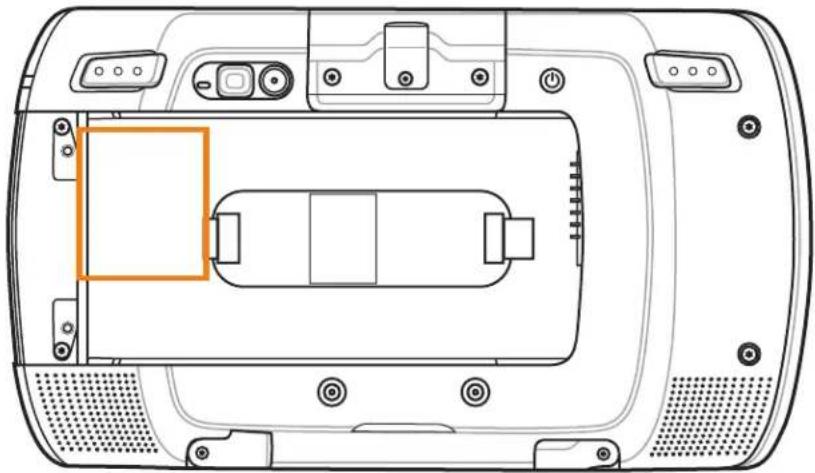
Top-down schematic of a device rear panel with labeled ports and an orange highlighted component (no text or symbols)Motorola responds to calls by email, telephone or fax within the time limits set forth in support agreements.
If your problem cannot be solved by Motorola Solutions Global Customer Support Center, you may need to return your equipment for servicing and will be given specific directions. Motorola is not responsible for any damages incurred during shipment if the approved shipping container is not used. Shipping the units improperly can possibly void the warranty.
If you purchased your product from a Motorola business partner, contact that business partner for support.
CHAPTER1GETTINGSTARTED
Features
This chapter provides the features of the ET1 and explains how to set it up for the first time.
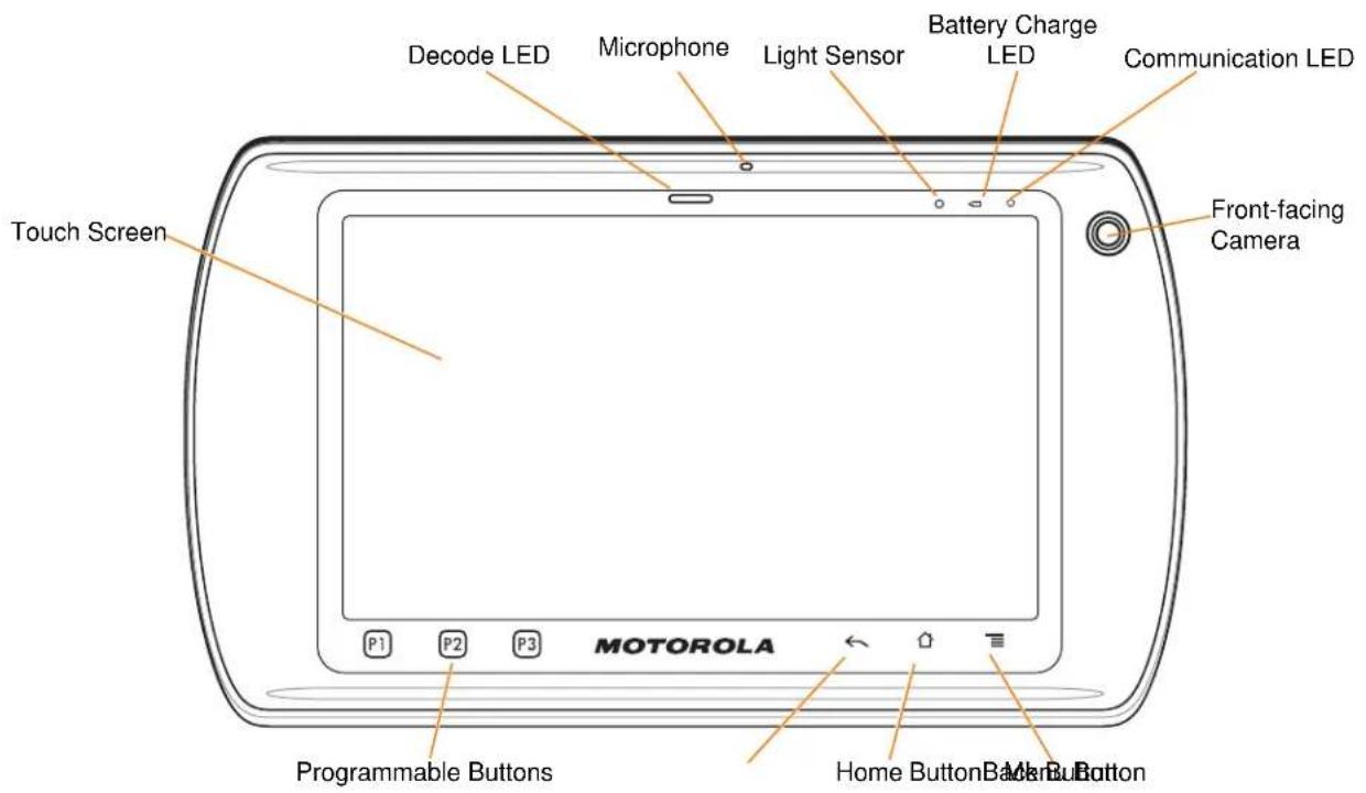
Figure1-1 ET1 Front View
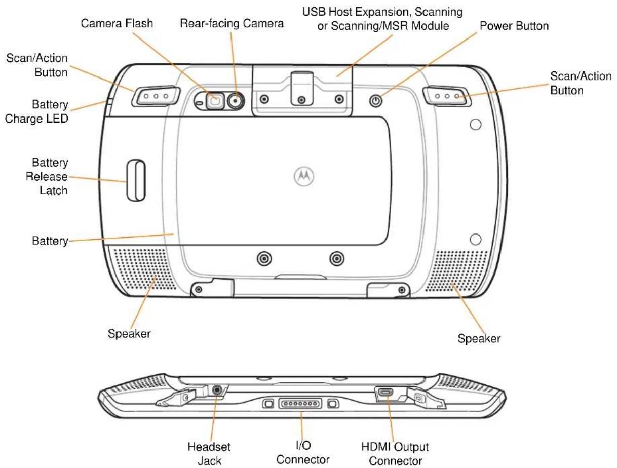
Figure1-2 ET1 Rear View
Table1-1 Features
| ItemFunction | |
| Decode LED Indicates decode | de functionality. Lights red when scanning in process. Lights green indicating a successful decode. |
| Microphone Use for making | voice recordings. |
| Light Sensor Determines ambient light for controlling display backlight intensity. | |
| Battery Charge LED Indicates battery charge state. | |
| Communication LED User programmable. | |
| Touch Screen Displays all information needed to operate the ET1. | |
| Front-facing Camera Use for capturing a front view picture.Use for making video calls with third-party video applications. | |
| P1 Decreases the volume (default). User configurable. | |
| P2 Increases the volume (default). User configurable. | |
| Item | Function |
| P3 Launches the Search application (default). User configurable. | |
Back Button  | Displays the previous screen.Closes the keyboard if the on-screen keyboard is open. |
Home Button  | Displays the Home screen with a single touch.Displays recently used applications when held for a short period of time. |
| Menu Button [BTAD] | Opens a menu with items that affect the current screen or application. |
| Right Scan/Action Button Opens the scan application (default). Programmable. | |
| Rear-facing Camera Takes photos, videos and captures bar code data. | |
| USB Host Expansion Module | Provides USB host connection to a peripheral. |
| Scanning Module Provides 1D and 2D bar code scanning. | |
| Scanning/MSR Module Provides 1D and 2D bar code scanning and magnetic stripe card reading. | |
| Power Button Press and hold to turn on the ET1.Press to turn the screen on or off.Press and hold to select one of these options:Silent mode - The device is set to vibrate mode; all sounds are disabled except for alarms.Airplane mode - Disable all wireless connections.Battery swap - Shutdown the device when replacing the battery.Reset - Reboot the ET1 if software stops responding.Power off - Turn off the ET1. | |
| Left Scan/Action Button Opens the scan application (default). Programmable. | |
| Speakers Provides audio output for video and music playback. | |
| Headset Jack Connects to mono headphones (3-wire, 2.5 mm plug). | |
| I/O Connector | Provides power to the device from cradles and cables and provides USB client and host communications. |
| HDMI Output Connector | Provides HDMI audio and video signals to an HDMI compatible monitor or television. |
Unpacking
Carefully remove all protective material from the ET1 and save the shipping container for later storage and shipping.
Verify the following items are in the box:
• ET1 Enterprise Tablet with 4 GB micro secure digital (SD) card installed
- Lithium-ion battery
- Quick Start Guide
• Regulatory Guide.
Inspect the equipment for damage. If any equipment is missing or damaged, contact the Motorola Solutions Global Customer Support Center immediately. See page xiii for contact information.
GettingStarted
To start using the ET1 for the first time:
- Install SIM card in an ET1N2 with GSM (optional)
- Install the battery
- Charge the ET1
- Power on the ET1
- Activate the ET1N2 on a mobile data network (optional).
InstallingtheSIMCard

NOTEET1N2 only.
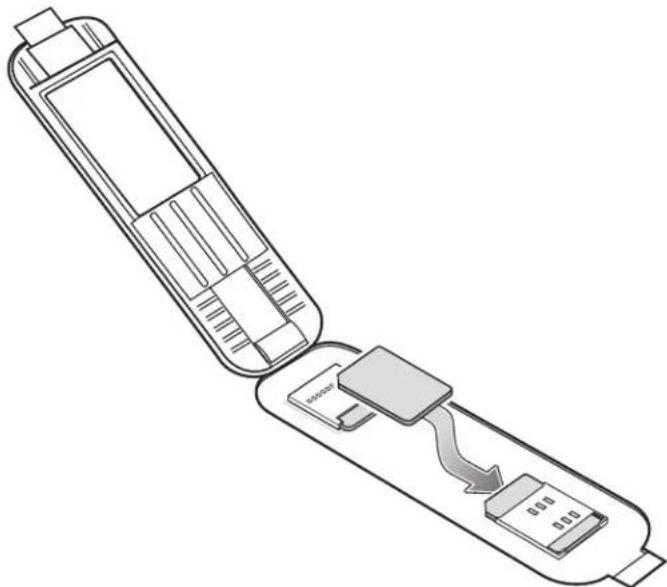
The ET1N2 requires an activated SIM card. Obtain the card from a service provider.
- Lift the access door.
natural_image
Diagram of a mobile phone casing showing internal components and signal flow (no text or symbols)Figure1-3 Installing SIM Card
-
Insert SIM card into the SIM holder with the contacts facing down and the cut edge facing away from the holder.
-
Close the access door.
InstallingtheBattery

CAUTION
Ensure that the correct battery is used with the ET1. On the ET1N0 use either the 4620 mAh battery, p82-149690-xx or the 5640 mAh battery, p/n 82-158261-xx. On the ET1N2 use only the 5640 mAh battery, p/n 82-158261-xx.
To install the battery:
- Align the tracks on the side of the battery with the rails in the battery compartment.
- Push the battery in until the battery release latch snaps into place.
- If the battery is charged, press and hold the Power button for two seconds until the splash screen appears.
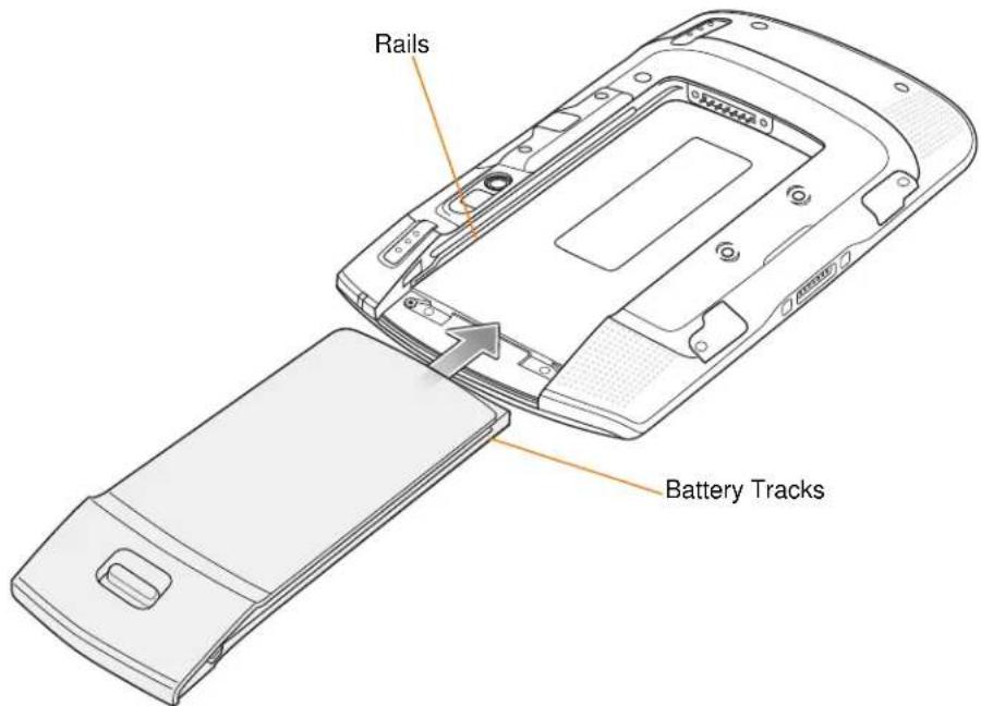
Figure1-4 Inserting the Battery
ChargingtheBattery

CAUTION Ensure that you follow the guidelines for battery safety described in Battery Safety Guidelines on page 8-1.
ChargingtheMainBattery
Before using the ET1 for the first time, charge the main battery until the Battery Charge light emitting diode (LED) turns solid green (see Table 1-2 on page 1-7 for charge status indications). To charge the ET1, use a cable or a cradle with the appropriate power supply. For information about the accessories available for the ET1, see Chapter 7, Accessories.
The ET1 is equipped with a memory backup battery that automatically charges from the fully-charged main battery. When using the ET1 for the first time, the backup battery requires approximately 40 hours to fully charge. This is also true any time the backup battery is discharged, which occurs when the main battery is removed for several hours. The backup battery retains random access memory (RAM) data in memory for at least 15 minutes (at room temperature) when the ET1's main battery is removed, when Battery Swap feature is used. When the ET1 reaches a very low battery state, the combination of main battery and backup battery retains RAM data in memory for at least 36 hours.
For cable and cradle setup and charging procedures refer to the ET1 Enterprise Tablet Integrator Guide.
USB/Charge Cable
• Single-slot USB Docking Cradle
• Four-slot Charge Only Docking Cradle.
To charge the main battery:
-
Connect the charging accessory to the appropriate power source. See Chapter 7, Accessories for more information.
-
Insert the ET1 into a cradle or attach to a cable. The ET1 begins charging. The Battery Charge LEDs blink yellow while charging, then turns solid green when fully charged. See Table 1-2 for charging indications.
The battery charges in less than six hours.
Table1-2 Battery Charge LED Status
| StatusIndication | |
| Off ET1 is not charging. | ET1 is not inserted correctly in the cradle.ET1 is not connected to a power source.Charger or cradle is not powered. |
| Slow Blinking Yellow(3 blinks every 2 seconds) | ET1 is charging. |
| Solid Green Charging complete. | |
| Fast Blinking Yellow(3 blinks/second) | Charging error, e.g.:Temperature is too low or too high.Charging has gone on too long without completion (typically eight hours). |
| Flashes Yellow three times when Power button pressed | Critical battery state. Battery too low to boot device. |
| Fast blinking Yellow (when Power button pressed) | Battery over-temperature condition. Device shuts down. Battery will not charge until temperature returns to normal operating value. |
ChargingTemperature
Charge batteries in temperatures from 0^ C to 40^ C ( 32^ F to 104^ F). Note that charging is intelligently controlled by the ET1. To accomplish this, for small periods of time, the ET1 or accessory alternately enables and disables battery charging to keep the battery at acceptable temperatures. The ET1 or accessory indicates when charging is disabled due to abnormal temperatures via its LED. See Table 1-2.
ChargingSpareBatteries
See Chapter 7, Accessories for information on using accessories to charge spare batteries.
PoweringOntheET1
Press the Power button until the Battery Charge LED flashes three times. The splash screen displays for about a minute as the ET1 initializes its flash file system. Note that these windows also appear upon reset.
WANActivation
In order to use the WAN radio for data communication, the ET1N2 must be activated on the service provider's network. By default, the ET1N2 is configured for a GSM network. To activate on a CDMA network, manual configuration is required.
Refer to the ET1 Enterprise Tablet Integrator Guide for detailed WAN configuration information.
GSMActivation
When the ET1N2 turns on it automatically configures for the network. If the SIM card requires a PIN, the PIN screen appears. Enter the PIN and touch OK.
CDMAActivation
Prior to using the ET1N2 on a CDMA network, the ET1 must be registered with the service provider. Contact the service provider to set up an account and provide the MEID number (located under the battery).
By default, the ET1N2 is configured for a GSM network. To activate on a CDMA network:
- Touch ≡ > Settings > Wireless & networks > Mobile networks > Technology preferences > Network mode.
- In the Network mode menu, select either Sprint or Verizon. The ET1 switches the modem firmware and the Activation Dialog box appears.
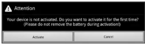
- Touch Activate. The ET1N2 begins the activation process. If the activation is unsuccessful, contact the service provider.
ReplacingtheBattery

CAUTIONDo not remove microSD card while in Battery Swap mode.
Ensure that the Battery Swap mode procedures are followed, otherwise the backup battery will deplete quickly and on the ET1N2, SIM card data corruption might occur.
To replace the battery:
- Press the Power button until the Device options menu displays.
- Touch Battery Swap. The Scan LED lights red.
- Wait until the Scan LED turns off.
- Press thumb against the side of the ET1 and battery. Using the index and middle fingers, move the battery release latch toward thumb.
- Pull the battery out of the battery compartment.
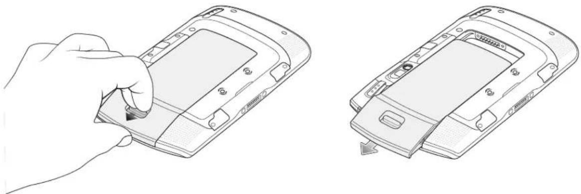
natural_image
Line drawing of a hand inserting a flip into a mobile phone case, showing the next step with a scroll wheel (no text or symbols present)Figure1-5 Removing the Battery
-
Align the tracks on the side of the replacement battery with the rails in the battery compartment.
-
Push the battery in until the battery release latch snaps into place.
-
Press the Power button to turn on the ET1.
ReplacingthemicroSDCard

CAUTION
Follow proper electrostatic discharge (ESD) precautions to avoid damaging the SD card. Proper ESD precautions include, but are not limited to, working on an ESD mat and ensuring that the operator is properly grounded.
Changing the microSD card can change the functionality of the ET1.
To replace the microSD card:
- Press the Power button until the Device options menu displays.
- Touch Power off.
- Touch OK.
1-10ET1 Enterprise TabletUserGuide
- Wait for the ET1 to power off completely.
- Press thumb against the side of the ET1 and battery. Using the index and middle fingers, move the battery release latch toward thumb.
- Pull the battery out of the battery compartment.
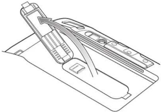
- Lift the access door.
natural_image
Technical line drawing of a mechanical assembly with no visible text or symbolsFigure1-6 Lift Access Door
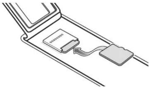
- Remove the microSD card from the card holder.
- Align the replacement microSD card with the card holder. Ensure that the contacts on the card are facing down and toward the card holder.
- Insert the microSD card into the card holder.
natural_image
Diagram of a device with a card and cable, no text or symbols presentFigure1-7 Insert microSD Card
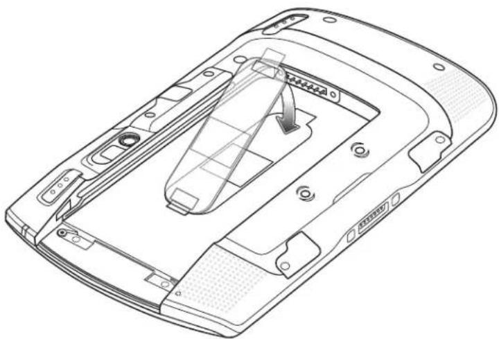
- Close the access door.
natural_image
Technical line drawing of a mechanical component with internal structure and mounting holes (no text or symbols)Figure1-8 Close Access Door
- Align the tracks on the side of the replacement battery with the rails in the battery compartment.
- Push the battery in until the battery release latch snaps into place.
- Press the Power button to turn on the ET1.
Handstrap
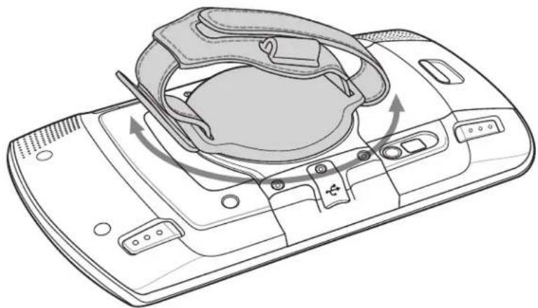
Use the optional 360-degree rotatable handstrap to securely hold the ET1 while working. Refer to the ET1 Enterprise Tablet Integrator Guide for information on installing the handstrap.
Rotate the handstrap for landscape or portrait viewing.
natural_image
Line drawing of a handheld device with a stylized head cover and scroll wheel (no text or symbols)Figure1-9 Rotate Handstrap 360 Degrees
Insert hand into the handstrap and tighten strap.
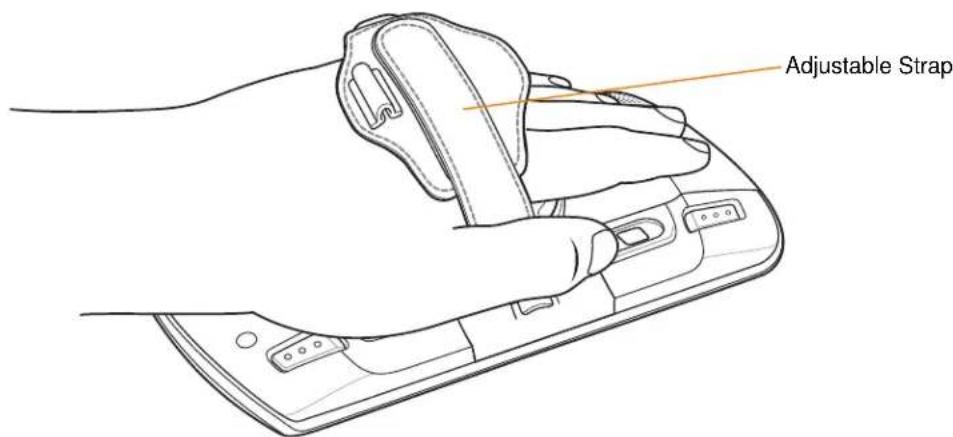
Figure1-10 Insert hand into Handstrap
BatteryManagement

NOTE Prior to checking the battery charge level, remove the ET1 from any AC power source (cradle or cable).
To check the charge status of the main battery, touch ≡ > Settings > About device > Status.
Battery status indicates that the battery is discharging and Battery level lists the battery charge (as a percentage of fully charged).
MonitorBatteryUsage
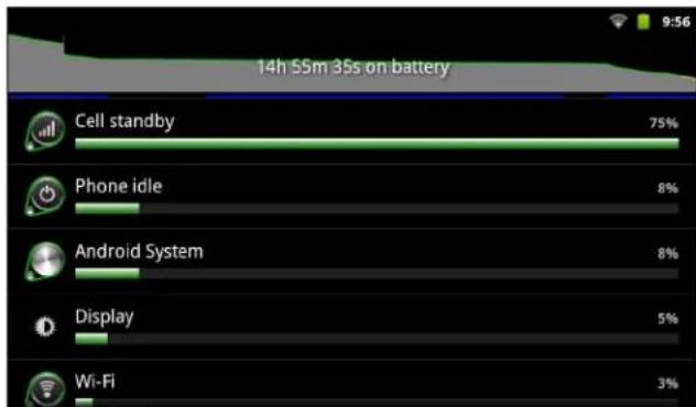
The Battery Use screen lists which applications consume the most battery power. Also use it to turn off applications that were downloaded if they are consuming too much power.
Touch > Settings > About device > Battery use.
bar
14h S5m 35s on battery | Device | Usage (%) | |---|---| | Cell standby | 75 | | Phone idle | 8 | | Android System | 8 | | Display | 5 | | Wi-Fi | 3 |Figure1-11 Battery Use Screen
The Battery Use screen lists the applications using the battery. The discharge graph at the top of the screen shows the rate of battery discharge since last charged (short periods of time when connected to a charger are shown as thin green lines at the bottom of the chart), and how long it has been running on battery power.
Touch an application in the Battery Use screen to display details about its power consumption. Different applications display different information. Some applications include buttons that open screens with settings to adjust power use.
LowBatteryNotification
When the battery charge drops below 20%, the ET1 displays a notice to connect the ET1 to power.
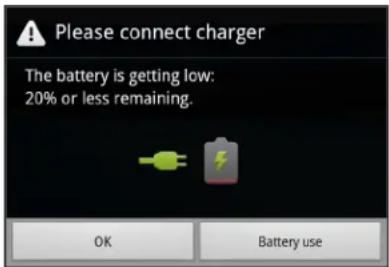
Figure1-12 Low Battery Notification
The user should replace the battery or charge the ET1 using one of the charging accessories.
When the battery charge drops below 10%, the ET1 goes into critical suspend mode to save data. The screen turns off. If the Power button is pressed, the Charge LED flashes yellow.
The user must replace the battery or charge the ET1 using one of the charging accessories to retain data.
BatteryOptimization
Observe the following battery saving tips:
- Leave the ET1 connected to AC power at all times when not in use.
- Set the screen to turn off after a short period of non-use.
- Reduce the screen brightness.
- Turn off all wireless radios when not in use. Note that the global positioning system (GPS) receiver is only turned on when a GPS application is using GPS.
• Turn off automatic syncing for Email, Calendar, Contacts, and other applications. - Use the Power Control widget to check and control the status of radios, the screen brightness, and syncing.
- Minimize use of applications that keep the ET1 from suspending, for example, music, GPS and video applications.
ChangingtheScreenTimeoutSetting
To set the ET1 to turn off after a short period of non-use:
- Touch > Settings > Display > Screen timeout.
- Select a value from the Screen timeout window. Options: 15 seconds, 30 seconds, 1 minute, 2 minutes, 10 minutes or 30 minutes.
- Touch .
ChangingtheBrightnessSetting
To change the brightness setting in order to conserve more battery power:
- Touch > Settings > Display > Brightness.
- If the Automatic Brightness checkbox is set, touch the checkbox to disable.
- Move the slider to the left to reduce the brightness.
-
Touch OK.
-
Touch .
TurningOfftheRadios
To turn off all radios:
- Touch > Settings > Wireless & networks.
-
Touch the Airplane Mode checkbox to disable all radios. The icon appears in the Status bar.
-
Touch .
SettingtheDateandTime
To set the date and time:
- Touch Settings > Date & time.
- Touch Set date.
- Use the + and - buttons to change the month, date and year.
- Touch Set.
- Touch Select time zone.
- Touch the time zone for the current location.
- Touch Set time.
- Use the + and - buttons to change the hour and minutes.
- Touch the AM/PM button to change.
-
Touch Set.
-
Touch .
DisplaySetting
ScreenBrightness
To set the screen brightness:
- Touch > Settings > Display > Brightness. The Brightness dialog box displays.
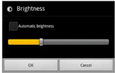
Figure1-13 Brightness Dialog Box
-
Check the Automatic brightness checkbox to set the ET1 to automatically adjust the brightness using the built-in light sensor.
Uncheck the checkbox to set the brightness manually. Use the slider to set a brightness level. -
Touch OK > .
ScreenRotation
To set the screen rotation:
- Touch ≡ > Settings > Display. The Display settings screen appears.
- Check Auto-rotate screen to set the ET1 to automatically switch orientation when the ET1 is rotated. Rotate the ET1 90 degrees to the left or to the right.
- Touch .
ScreenTimeout
To set the screen timeout:
- Touch > Settings > Display > Screen timeout. The Screen timeout menu appears.
- Select one of the timeout values. Options: 15 seconds, 30 seconds, 1 minute, 2 minutes, 10 minutes, or 30 minutes.
- Touch .
SoundSettings
Use Sound settings to configure media and alarm volumes. Touch ≡ > Settings > Sound.
GeneralSoundSettings
Silent Mode - Check to silence all sounds except the audio from music, videos and alarms. Note: to silence media and alarms, go to the settings for the specific application.
Vibration - Configure the ET1 when to vibrate when it receives a notification. Options: Always, Never, Only in Silent mode, or Only when not in Silent mode.
Volume - Controls the volume of media, alarms and notifications. Use the sliders to set a volume levels.
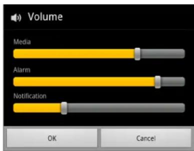
Figure1-14 Volume Dialog Box
NotificationsSettings
- Notification ringtone - Opens a dialog box to select the ringtone to sound when a notification is received.
FeedbackSettings
• Audible selection - Check to play a sound when making screen selections.
- Screen lock sounds - Check to play a sound when locking and unlocking the screen.
- Haptic feedback - Check to have the ET1 vibrate when touching soft keys and on certain screen interactions.
CHAPTER2USINGTHEET1
Introduction
This chapter describes the screens, status and notification icons, and controls on the ET1, and provides basic instructions for using the ET1.
HomeScreen
The Home screen displays when the ET1 turns on. Depending upon the configuration, the Home screen might appear different. Contact your system administrator for more information.
After a suspend or screen time-out, the Home screen displays with the lock sliders. Slide 🔒 up to un-lock the screen. For screen locking information see Un-Locking the Screen on page 2-14.
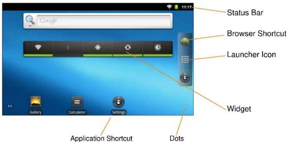
Figure2-1 Home Screen
The Home screen consists of the following:
- Status Bar - Displays the time, status icons (right side), and notification icons (left side). For more information see Status Icons on page 2-2 and Managing Notifications on page 2-5.
- Launcher Icon - Opens the application window. See Applications on page 2-12.
- Browser Icon - Opens the Browser application.
- Widgets - Launches stand-alone applications that run on the Home screen.
- Shortcut Icons - Opens applications installed on the ET1.
The Home screen provides four additional screens for placement of widgets and shortcuts. Swipe the screen left or right to view the additional screens. The dots in the lower left and right corners indicate which screen is being viewed.
Touch and hold the dots or touch and hold the (launcher icon) to view thumbnails of all the screens. Five thumbnails appear representing the five screens. Touch one of the thumbnails to view that screen.
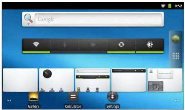
Figure2-2 Home Screen Thumbnails
StatusBar
The Status bar displays the time, notification icons (left side) and status icons (right side).
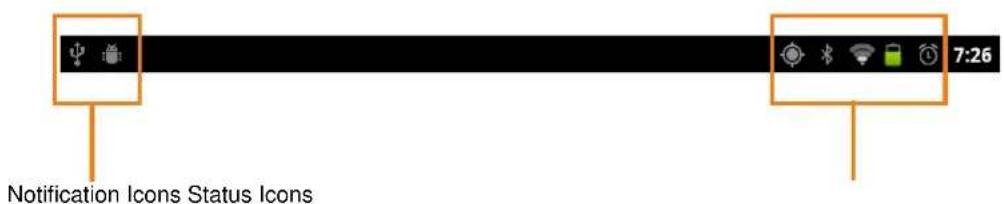
Figure2-3 Notification and Status Icons
If there are more notifications than can fit in the Status bar, + displays indicating that more notifications exist. Open the Notifications panel to view all notifications and status.
StatusIcons
Table 2-1 lists Status icons that may appear.
Table2-1 Status Icons
| IconDescriptionIconDescription | |||
 | Indicates that GPS is on. Indicates that the ET1 is receiving location data from GPS. | ||
| [CDXW] | Indicates that Bluetooth is on. Indicates that the FT1 is connected to a   | ||
| [W304] | Indicates that the Alarm is active. Indicates that all soundds except media and alarms are silenced and vibrate mode is active.[CS4H] | ||
| [S406] | Indicates that the ringer is silenced. Connected to Wi-Fi network[CS4H] | ||
 | Indicates that the battery charge is very low. indicates that the battery charge is low. | ||
 | Indicates that the battery is partially drained. | ||
 | Indicates that the battery is charging. Indicates that the Airplane Mode is active. All radios are turned off. All radios are turned off. | ||
| [8246] | Mobile network signal strength. No mobile network signal. | ||
 | Connected to an EDGE network. EDGE in use. | ||
 | Connected to a 3G network. 3G network in use. | ||
| [kZWC] | Connected to an HSPA network. HSPA network use.[BYDW] | ||
 | Connected to a 1X CDMA network. | ||
 | Connected to an EVD0 network. EVD0 network 'se.  | ||
 | Roaming from a GSM network. Roaming from a CDMA network.  | ||
 | No SIM card installed. | ||
NotificationIcons
Table 2-2 lists the possible notification icons. See Managing Notifications on page 2-5 for information about responding to these notifications. In addition these icons, installed applications may display their own notification icons.
Table2-2 Notification Icons
| IconDescriptionIconDescription | |||
 | Indicates that more notifications are available for viewing. |  | Indicates that data is syncing. |
 | Indicates an upcoming event. Indicates that an open Wi-Fi network is available. |  | |
 | Indicates that a song is playing. Indicates that a problem with sign-in or sync has occurred. |  | |
 | Indicates that the ET1 is uploading data. Indicates that the microSD card is almost full. |  | |
| [KW25] | Indicates that the ET1 is downloading data when animated and download is complete when static. |  | Indicates that the ET1 is connected via USB cable. |
 | Indicates that the ET1 is connected to or disconnected from virtual private network (VPN). | [ATSC] | Preparing SD card. |
 | Indicates that USB debugging is enabled on the ET1. | [STXX] | Indicates that the MultiUser feature is enabled. |
 | Indicates that a new user is logging in. Indicates that the ET1 has received a text message. |  | |
ManagingNotifications
Notification icons report the arrival of new messages, calendar events, and alarms, as well as ongoing events. When a notification occurs, an icon appears in the Status bar with a brief description. See Table 2-2 on page 2-4. Open the Notifications panel to view a list of all the notifications.
To open the Notification panel:
- drag the Status bar down from the top of the screen. or
- On the Home screen, touch ▷Notifications.
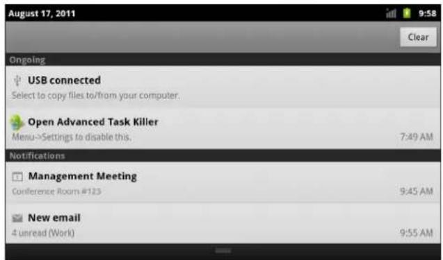
Figure2-4 Notification Panel
To respond to a notification, open the Notifications Panel and then touch a notification. The Notifications Panel closes and the subsequent activity is dependent on the notification.
To clear all notifications, open the Notifications Panel and then touch Clear. All event-based notifications are removed. Ongoing notifications remain in the list.
To close the Notification Panel, drag the bottom of the Notifications Panel to the top of the screen or touch ←.
Widgets
Widgets are self-contained applications placed on the Home screen to access frequently used features.
To add a Widget to the Home screen:
- Go to the desired Home screen.
- Touch and hold on the screen until the Add to Home screen menu appears.
- Touch Widgets. The Choose widget menu appears. Table 2-3 lists the default widgets available.
- Touch a widget to add it to the Home screen.
To remove a widget from the Home screen, touch and hold the widget icon until it enlarges and the ET1 vibrates. Drag the icon to find release.
Table2-3 Default Widgets
| IconDescriptionIconDescription | |||
 | Analog Clock - Displays an analog clock on the screen. |  | Calendar - Displays a calendar on the screen. |
 | Home screen tips - Displays Home screen tip information. |  | Music - Displays the music player control on the screen. |
 | Picture frame - Displays a photo from the Gallery on the screen. |  | Power Control - Displays the Power Control widget for controlling Wi-Fi, Bluetooth and global positioning system (GPS) connections and synchronization and brightness settings. |
 | Search - Displays the Search Widget for searching the web, applications and contacts. | ||
Shortcuts
Use Shortcuts for quick access to applications. To create a shortcut:
- Go to the desired Home screen.
- Touch and hold on the screen until the Add to Home screen menu appears.
- Touch Shortcuts. The Select shortcut menu appears.
- Touch a selection from the menu. Menu items vary depending upon applications installed on the ET1.
- Follow the instructions on the screen.
To remove a shortcut from the Home screen, touch and hold the shortcut icon until it enlarges and the ET1 vibrates. Drag the icon to find release.
Folders
Use Folders to organize items. To add a folder:
- Go to the desired Home screen.
- Touch and hold on the screen until the Add to Home screen menu appears.
- Touch Folders. The Select folder menu appears.
-
Touch an option:
-
New folder - Creates a new empty folder.
• All contacts - Creates a folder containing all contacts. - Bluetooth received - Creates a folder containing a list of items received from Bluetooth.
- Contacts with phone numbers - Creates a folder containing contacts with stored phone numbers.
• Starred contacts - Creates a folder containing Favorite contacts.
To remove a folder from the Home screen, touch and hold the folder icon until it enlarges and the ET1 vibrates. Drag the icon to 📋nd release.
HomeScreenWallpaper

NOTEUse of Live Wallpaper may reduce battery life.
To change the Home screen wallpaper:
- Touch >Wallpaper
or
touch and hold on the Home screen until the Add to Home screen menu appears then touch Wallpapers.
- Touch Gallery, Live wallpapers or Wallpapers.
• Gallery - Select to use an image stored on the ET1.
• Live wallpapers - Select to use an animated wallpaper image.
- Wallpapers - Select to use a wallpaper image.
- Touch Save or Set wallpaper.
MovingItemsontheHomeScreen
To move an item on the Home screen:
- Touch and hold the item until it enlarges.
- Drag the item to a new location.
Pause at the edge of the screen to drag the item onto an adjacent Home screen. - Lift finger to place item.
RemovinganItemfromtheHomeScreen
To remove an item from the Home screen:
- Touch and hold the item until it enlarges.
-
Drag the item over .
-
When the icon turns red, lift finger. The item is removed from the Home screen.
UsingtheTouchscreen
Use the multi-touch sensitive screen to operate the ET1.
- Touch - Touch to:
- select items on the screen
- type letters and symbols using the on-screen keyboard
-
press on-screen buttons.
-
Touch and Hold - Touch and hold:
- an item on the Home screen to move it to a new location or to the trash.
- the Launcher icon or dots on the Home screen to open the Home screen thumbnails.
- an item in the Launcher to create a shortcut on the Home screen.
- the Home screen to open a menu for customizing the Home screen.
- an empty area on the Home screen until the menu appears.
- Drag - Touch and hold an item for a moment and then move finger on the screen until reaching the new position.
-
Swipe - Move finger up and down or left and right on the screen to:
-
unlock the screen
• view additional Home screens
• view additional application icons in the Launcher window - view more information on an application's screen.
- Double-tap - Tap twice on a web page, map, or other screen to zoom in and out.
- Pinch - In some applications, zoom in and out by placing two fingers on the screen and pinching them together (to zoom out) or spreading them apart (to zoom in).
WorkingwithMenus
There are two kinds of menus: options menus and context menus.
OptionsMenus
The Options menu contain items that apply to the activities of the current screen or application. To open the Options menu touch ☐. Some screens have more items than can fit in the menu. Touch More to open a menu of additional items.
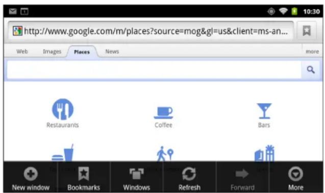
Figure2-5 Options Menu Example
ContextMenus
Context menus contain functions that apply to a specific item on the screen. To open a context menu, touch and hold an item on the screen.
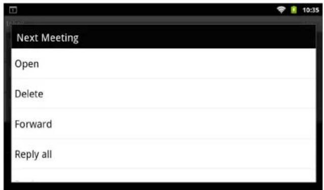
Figure2-6 Context Menu Example
UsingtheOn-screenKeyboard
Use the on-screen keyboard to enter text in a text field. To configure the keyboard settings, touch then select keyboard settings. Refer to the ET1 Enterprise Tablet Integrator Guide for more information.
EnterText
To enter text:
- Touch a text field. The on-screen keyboard appears.
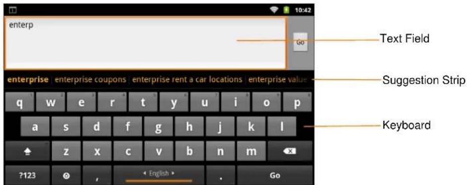
Figure2-7 On-screen Keyboard
- Touch keys on the keyboard to enter text.
The entered text appears in the text field and in the suggestion strip. When the keyboard has a suggestion, the word is underlined in the text field and the suggestions appear in orange. The boldfaced suggestion at the left of the strip is the keyboard's best suggestion. Drag the strip to the left to view additional suggestions.
- Press space or a punctuation mark to enter the boldfaced suggested word.
- Touch to erase characters to the left of the cursor.
- Touch to close the keyboard.
View, edit, or delete the words added to the dictionary. Refer to the ET1 Enterprise Tablet Integrator Guide for more information.
EnteringNumbers, Symbols, and SpecialCharacters
To enter numbers and symbols:
- Touch and hold one of the top-row keys until a menu appears then select a number. Keys with alternate character with the characteripsis (
- Touch and hold the Shift key with one finger, touch one or more capital letters or symbols to enter them, and then lift both fingers to return to the lowercase keyboard.
- Touch to switch to the numbers and symbols keyboard.
- Touch the ALT key on the numbers and symbols keyboard to view additional symbols.
To enter special characters, touch and hold a number or symbol key to open a menu of additional symbols.
• A larger version of the key displays briefly over the keyboard.
- Keys with alternate characters display an ellipsis ( ... ) below the character.
EditingText
Edit entered text and use menu commands to cut, copy, and paste text within or across applications. Some applications do not support editing some or all of the text they display; others may offer their own way to select text.
To edit text:
- Touch the text. The on-screen keyboard appears with the text in the text field.
- Touch the text to edit. A cursor appears with an orange tab.
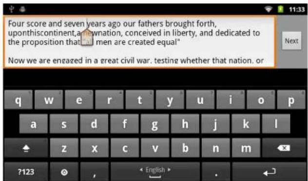
Figure2-8 Cursor
- Drag the orange tab to the location to edit text. The orange tab disappears after a few moments. To make it reappear, touch the text again.
- Type new text or delete existing text.
- Press when finished typing to close the keyboard.
SelectText
To select text to cut, copy, delete or replace:
-
Touch the text. The on-screen keyboard appears with the text in the text field.
-
Touch and hold the text to select. The Edit text menu appears.
-
Touch Select word or Select all.
The selected text is highlighted in orange, with tabs at each end of the selected text.
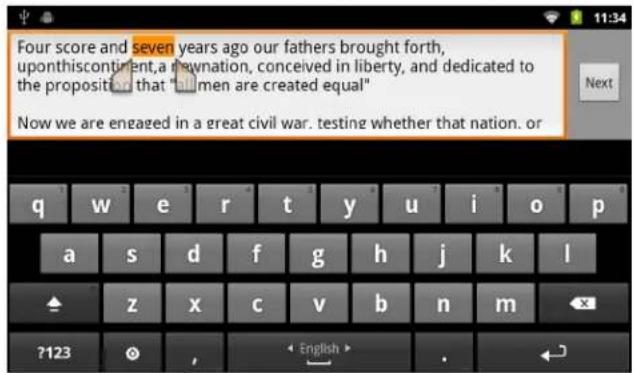
Figure2-9 Select Text
-
Drag either tab to expand or reduce the selected text.
-
To delete the selected text touch the Delete key.
-
To replace the selected text, type new text to overwrite the selected text or touch the text and touch Paste from the Edit text menu.
-
To cut or copy text, touch the selected text and then touch Cut or Copy from the Edit text menu.
ChangingtheKeyboardLanguage
The keyboard can be set to use different language layouts. Refer to the ET1 Enterprise Tablet Integrator Guide for more information. To change the current keyboard language:
-
Touch and hold the spacebar.
-
Slide finger to the left or right until the language name appears in the pop-up window.
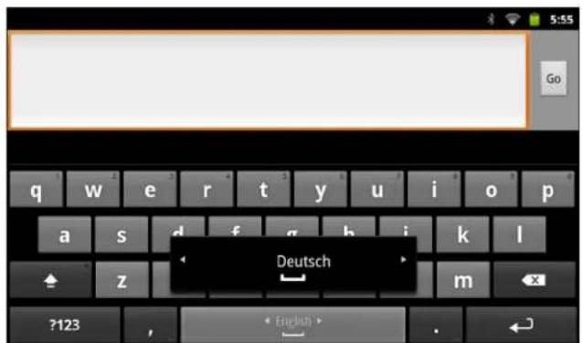
Figure2-10 Change Keyboard language
- Lift finger. The keyboard layout changes to the new language.
Applications
The Launcher displays icons for all installed applications. Table 2-4 list the default applications on the ET1. Refer to the ET1 Enterprise Tablet Integrator Guide for information on installing and uninstalling application.
Table2-4 ET1 Default Applications
| IconDescriptionIconDescription | |||
 | Browser - Use to access the Internet or intranet. |  | Calculator - Provides the basic and scientific arithmetic functions. |
 | Calendar - Use to manage events and appointments. |  | Camera - Take photos or record videos. For more information see Viewing Photos and Videos on page 6-6. |
 | Clock - Use to schedule alarms for appointments or as a wake-up. |  | Contacts - Use to manage contact information. |
 | DataWedge - Enables data capture using the camera or optional scanner. |  | Downloads - lists all downloads files. |
 | Email - Use to send and receive email. |  | File Browser - Organize and manage files on the ET1. See Using File Browser on page 2-18 for more information. |
 | Gallery - Use to view photos stored on the microSD card. For more information, see Viewing Photos and Videos on page 6-6. |  | MSP Agent - Enables management of the ET1 from an MSP server. Requires the purchase of an appropriate MSP client license per device to suit the level of management functionality required. |
 | Music - Play music stored on the microSD card. |  | Rapid Deployment - Allows the ET1 to stage a device for initial use by initiating the deployment of settings, firmware and software. Requires the purchase of an MSP client license per device. |
 | Search - Use the Google search engine to search the Internet and the ET1. |  | Settings - Use to configure the ET1. For more information, refer to the ET1 Enterprise Tablet Integrator Guide. |
 | AppLock Administrator - Use to configure the Application Lock feature. This icon appears after the optional applications is installed. |  | MultiUser Administrator - Use to configure the MultiUser feature. This icon appears after the optional applications is installed. |
 | Secure Storage Administrator - Use to configure the Secure Storage feature. This icon appears after the optional applications is installed. |  | DWDemo - Provides a way to demonstrate the data capture features using the Camera, Scanning Module or Magnetic Stripe Reader. |
To open the Launcher, on the Home screen touch . The Launcher window displays.
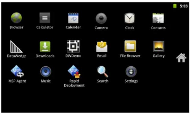
Figure2-11 Launcher Window
Slide the Launcher window up or down to view more application icons. Touch an icon to open the application.

NOTE See Shortcuts on page 2-6 for information on creating a shortcut on the Home screen.
To switch between recently used applications:
- Touch and hold ↑. A small window appears on the screen with icons of recently used applications.
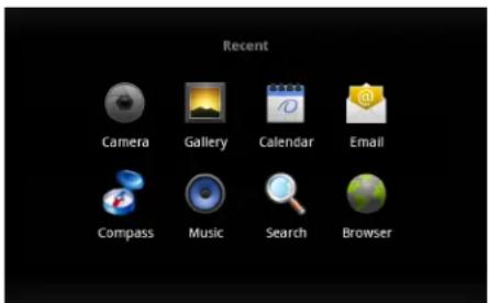
Figure2-12 Recently Used Applications
- Touch an icon to open it or press
to return to the current screen.
Un-LockingtheScreen
Use the Lock screen to protect access to data on the ET1. Some email account require locking the screen. Refer to the ET1 Enterprise Tablet Integrator Guide for information on setting up the locking feature. The Locking feature functions differently in Single User mode or Multiple User mode.
SingleUserMode
When locked, a pattern, PIN or password is required to unlock the ET1. Press the Power button to lock the screen. The ET1 also locks after a pre-defined time-out.
Press and release the Power button to wake the ET1.
The Lock screen displays. Slide up to unlock the screen. If the Pattern screen unlock feature is enabled, the Pattern screen appears instead of the Lock screen.
If the PIN or Password screen unlock feature is enabled, enter the PIN or password after unlocking the screen.
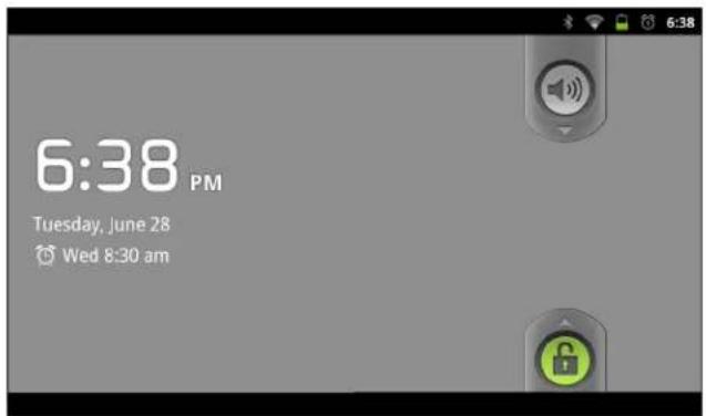
Figure2-13 Lock Screen
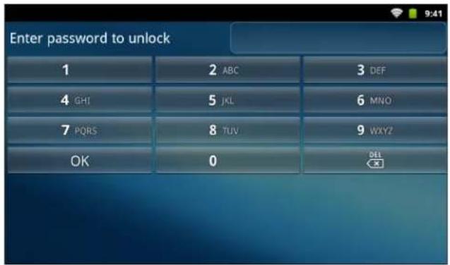
Figure2-14 PIN Screen
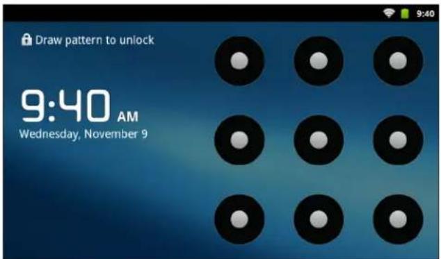
Figure2-15 Pattern Screen
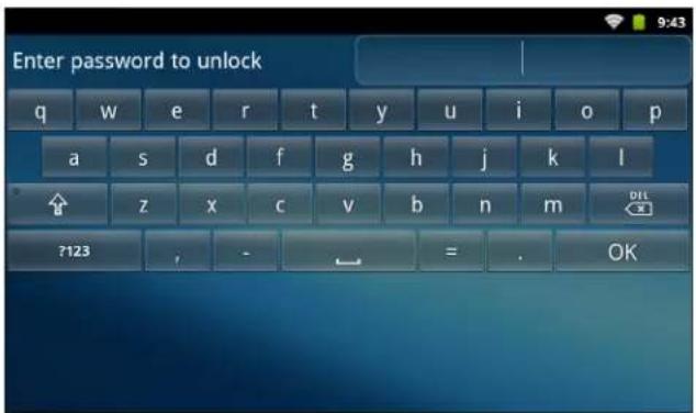
Figure2-16 Password Screen
MultiUserLogin
With MultiUser login, multiple users can log on to the ET1 with each user having access to various applications and features. When enabled, the Login screen appears after powering on, resetting or after the ET1 wakes from suspend mode.
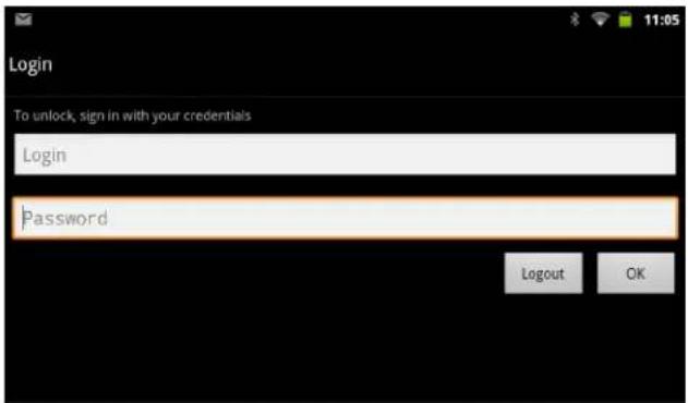
Figure2-17 Multiple User Log In Screen
- In the Login text field, enter the username.
- In the Password text field, enter the password.
- Touch OK.
After a resume from suspend, the user must enter the password.
To logout:
- Drag the Status Bar down from the top of the screen.
- Touch MultiUser is active.
- Touch Logout.
- The Login screen appears.
ResettingtheET1
There are two reset functions, Soft Reset and Hard Reset.
SoftReset
Perform a Soft Reset if applications on the ET1 stop responding. To perform a Soft Reset:
- Press and hold the Power button until the Device options menu appears.
- Touch Reset.
- The ET1 shuts down and then reboots.
HardReset

CAUTION Performing a Hard Reset with a SIM card installed in the ET1N2 may cause damage or data corruption to the SIM card.
Perform a Hard Reset if the ET1 stops responding. To perform a Hard Reset, simultaneously press the Power, Left Scan/Action and Right Scan/Action buttons. The ET1 shuts down and then reboots.
WakingtheET1
The wake-up conditions define what actions wake up the ET1 after it has gone into suspend mode. The ET1 can go into suspend mode by either pressing the Power button or automatically by a time-out settings. Table 2-5 list the default wake up conditions.
Table2-5 Wake-up Default Settings
| ConditionforWake-upPowerButtonAutomaticTime-out | ||
| AC power is applied. No Yes | ||
| ET1 is inserted into a cradle. | Yes | Yes |
| ET1 is removed from a cradle. | No No | |
| ET1 is connected to a USB device. | No Yes | |
| ET1 is disconnected from a USB device. | No Yes | |
Table2-5 Wake-up Default Settings (Continued)
| ConditionforWake-upPowerButton | AutomaticTime-out |
| Scan/Action button is pressed. Yes Yes | |
| The screen is touched. No No | |
| Bluetooth communication Yes Yes |
WakingUptheET1
If the ET1 is not used for a while, the screen dims and then darkens to conserve the battery.
To wake the ET1, press the Power button.
The Lock screen displays. Slide up to unlock the screen. If the Pattern screen unlock feature is enabled, the Pattern screen appears instead of the Lock screen. See Un-Locking the Screen on page 2-14.
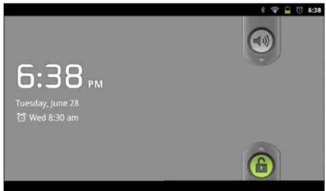
Figure2-18 Locked Screen
UsingFileBrowser
Use the File Browser application to view and mange files on the ET1.
To open File Browser, touch > File Browser.
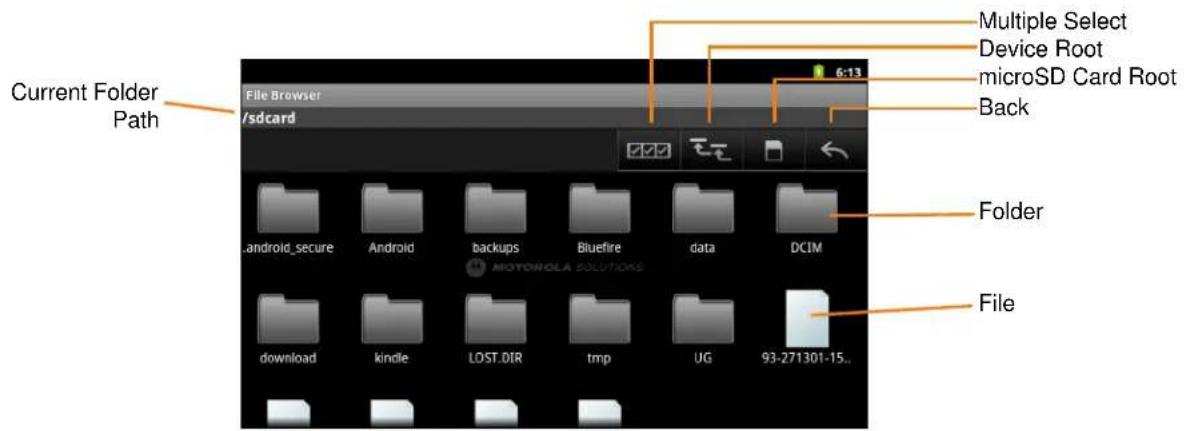
Figure2-19 File Browser Screen
- Touch select multiple files/folder.
- Touch the view to the ET1 internal storage root folder.
- Touch to view the microSD card root folder.
- Touch review the previous folder or to exit the application.
- Touch a folder icon to open the folder.
- Touch and hold an item to perform an operation on that item. Select one of the options from the menu:
• Information - View detailed information about the file or folder.
- Move - Move the file or folder to a new location.
- Copy - Copy the select file.
- Delete - Delete the selected file.
- Rename - Rename the select file.
- Open as - Open the selected file as a specific file type.
- Touch to view additional functions.
- Touch ≡ > New Folder to create a new folder in the current folder.
- Touch >Search to search for a file or folder.
- Touch ≡ > Sort to sort the list by name, by type, by size or by date.
- Touch ≡ > Refresh to re-display the contents of the current folder.
- Touch > Change View to change the folder view from tile to list format.
- Touch > More > Change Size to change the size of the icons: Large, Normal or Small.
Touch the Current Folder path to manually enter a path and folder name.
Messaging
Use Messaging to exchange text messages (SMS) with other ET1 devices and mobile phones.
OpeningMessaging
To open the Messaging application touch > Messaging. The Messaging window opens,
- Touch New message to start a new text message.
- Touch an existing message thread to open it.
SendaTextMessage
The user can send text (SMS) messages of up to 160 characters to another device. If the user keeps typing after the limit, the message is delivered as a series of messages (if supported by the carrier).
To send a text message:
- On the Messaging screen, touch New message.
- In the To field, enter a mobile phone number or contact name.
- Touch the Type to compose text box to start entering a message.
As the 160-character limit nears, a counter appears in the top right corner of the text box to indicate how many characters are left. If the user goes over that limit, a new message is created, which is joined with its predecessors when received.
If the user presses Back while composing a message, it's saved as a draft in the Messaging window. Touch the message to resume composing it.
- Touch Send.
The Message window opens, with the message after the user's name. Responses appear in the window. As the user views and sends additional messages, a message thread is created.
RespondingtoaMessage
A new message notification appears and a new message icon appears in the Status bar.
Touch the new message notification, the Message window appears.
Touch and hold a message until the Message options menu appears with number of options for working with the message and its sender's information.
ForwardaMessage
To forward a message:
- Touch and hold a message until the Message options menu appears.
- Touch Forward.
- Enter a recipient for the message and edit the content.
- Touch Send.
LockaMessage
Lock a message so it can not be deleted if the storage limits is reached. If the user tries to delete a thread that contains a locked message, the user is asked to confirm deleting it.
- Touch and hold a message in a Message window until the Message options menu appears.
- Touch Lock message. A lock icon appears to the right of the message.
To unlock a message, Touch and hold a message until the Message options menu appears. Touch Unlock message.
ViewMessageDetails
To view details about a specific message:
- Touch and hold a message until the Message options menu appears.
- Touch View message details. The Message details dialog box appears.
- Touch OK.
DeleteaMessageThreadfromtheMessagingWindow
To delete a message thread:
- Touch and hold the message thread. until the a menu appears.
- Touch Delete thread.
Also touch Menu > Delete threads to delete all message threads from the window.
ChangingMessagingSettings
To change Messaging settings:
- Touch > Messaging > Menu > Settings.
- Storage Settings
- Delete old messages - Check to delete older messages in a thread when the text message limit is reached. Uncheck to keep all messages.
- Text message limit - Touch to set the number of messages to save per thread of text messages. When the limit is reached, older messages are deleted if Delete old messages is checked.
• Text message (SMS) settings
• Delivery reports - Check to receive delivery reports for the sent messages.
- Manage SIM card messages - View text messages stored on a SIM card.
- Notification settings
- Notifications - Check to receive a notification whenever the ET1 receives a new message.
- Select ringtone - Opens a dialog box to select the ringtone to sound when the ET1 receives a new message notifications.
- Vibrate - Opens a dialog box to set the ET1 to vibrate whenever it receives a new message notification, only in Silent mode, or never.
CHAPTER3DATACAPTURE
Introduction
The ET1 offers the following data capture options:
- Scanning Module
- Scanning/MSR Module
- integrated digital camera
• optional CS3070 Bluetooth laser scanner.

NOTE DataWedge is installed and enabled on the ET1 by default.
ScanningModules
The ET1 with an integrated Scan Module has the following features:
- Omnidirectional reading of a variety of bar code symbologies, including the most popular linear, postal, PDF417, and 2D matrix code types.
- Advanced intuitive laser aiming cross-hair for easy point-and-shoot operation.
The modules uses digital camera technology to take a digital picture of a bar code, stores the resulting image in its memory, and executes state-of-the-art software decoding algorithms to extract the data from the image.
OperationalModes
The ET1 with an integrated imager supports two modes of operation, listed below. Activate each mode by pressing either Scan/Action buttons.
- Decode Mode: In this mode, the ET1 attempts to locate and decode enabled bar codes within its field of view. The imager remains in this mode as long as the user holds the Scan/Action button, or until it decodes a bar code.

NOTETO enable Pick List Mode, configure in DataWedge.
- Pick List Mode: This mode allows the user to selectively decode a bar code when more than one bar code is in the ET1's field of view. To accomplish this, move the aiming crosshair over the required bar code to decode only this bar code. This feature is ideal for pick lists containing multiple bar codes and manufacturing or transport labels containing more than one bar code type (either 1D or 2D).
DigitalCamera
ET1 with an integrated camera based bar code scanning solution with the following features:
- Omnidirectional reading of a variety of bar code symbologies, including the most popular linear, postal, QR, PDF417, and 2D matrix code types.
• Cross-hair reticle for easy point-and-shoot operation. - Picklist mode to decode a particular bar code from many in the field of view.
The solution uses the advanced camera technology to take a digital picture of a bar code, and executes state-of-the-art software decoding algorithms to extract the data from the image.
LaserScanning
The optional CS3070 scanner has the following features:
- Reading of a variety of bar code symbologies, including the most popular linear, postal, and 1-D code types.
- Intuitive aiming for easy point-and-shoot operation.
ScanningConsiderations
Typically, scanning is a simple matter of aim, scan, and decode and a few quick trial efforts master it. However, consider the following to optimize scanning performance:
- Range
Any scanning device decodes well over a particular working range — minimum and maximum distances from the bar code. This range varies according to bar code density and scanning device optics.
Scanning within range brings quick and constant decodes; scanning too close or too far away prevents decodes. Move the scanner closer and further away to find the right working range for the bar codes being scanned.
- Angle
Scan angle is important for promoting quick decodes. When laser beams reflect directly back into the scanner from the bar code, this specular reflection can "blind" the scanner.
To avoid this, scan the bar code so that the beam does not bounce directly back. But don't scan at too sharp an angle; the scanner needs to collect scattered reflections from the scan to make a successful decode. Practice quickly shows what tolerances to work within.
- Hold the ET1 farther away for larger symbols.
- Move the ET1 closer for symbols with bars that are close together.

NOTE Scanning procedures depend on the application and ET1 configuration. An application may use different scanning procedures from the one listed above.
BarCodeCapturewithScanningorScanning/MSRModule
To capture bar code data:
- Ensure that an application is open on the ET1 and a text field is in focus (text cursor in text field).
- Point the top of the ET1 at a bar code.
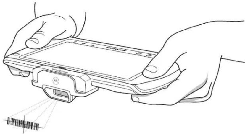
natural_image
Line drawing of two hands holding a device with a sensor and barcode symbol (no text or labels)Figure3-1 Bar Code Scanning
- Press and hold either Scan/Action button.
The red laser aiming pattern turns on to assist in aiming. Ensure the bar code is within the area formed by the cross-hairs in the aiming pattern. The aiming dot is used for increased visibility in bright lighting conditions.
The Scan/Decode LED lights red to indicate that scanning is in process, then lights green, a beep sounds and the ET1 vibrates, by default, to indicate the bar code was decoded successfully. Note that when the ET1 is in Pick List Mode, the ET1 does not decode the bar code until the center of the crosshair touches the bar code.
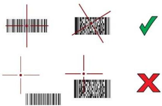
Figure3-2 Aiming Pattern
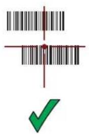
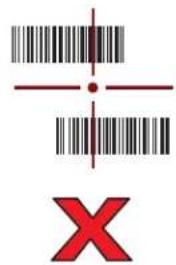
Figure3-3 Pick List Mode with Multiple Bar Codes in Aiming Pattern
- Release the scan button.
- The captured data appears in the text field.
BarCodeCapturewithIntegratedCamera
To capture bar code data:
- Ensure that an application is open on the ET1 and a text field is in focus (text cursor in text field).
- Aim the rear-facing camera at a bar code.
- Press and hold either Scan/Action button. By default, a preview window appears on the screen. The Decode light emitting diode (LED) lights red to indicate that data capture is in process.
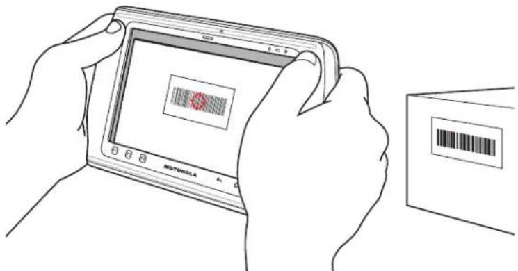
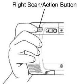
Figure3-4 Sample Scan Application with Preview Window
- Move the ET1 until the bar code is centered.
- The Decode LED lights green, a beep sounds and the ET1 vibrates, by default, to indicate the bar code was decoded successfully.
- The captured data appears in the text field.
BarCodeCapturewithCS3070BluetoothScanner
The CS3070 Bluetooth scanner captures bar code data, and transmits it to the ET1 via Bluetooth. The scanner supports Bluetooth human interface device (HID) connection to the ET1 where the scanner emulates a
keyboard, as well as Serial Port Profile (SPP) connection where the scanner behaves as if there is a serial connection. Refer to the ET1 Enterprise Tablet Integrator Guide for setup and configuration information.
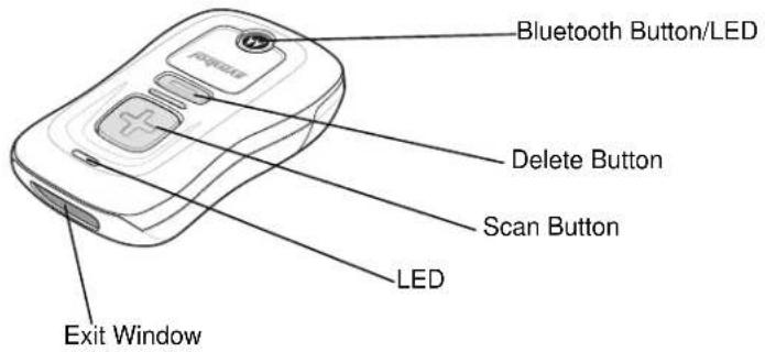
Figure3-5 CS3070 Bluetooth Scanner
To capture bar code data:
- Ensure that an application is open on the ET1 and a text field is in focus (text cursor in text field).
- Aim the scanner at the bar code.
- Press the scan (+) button.
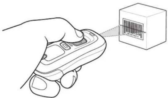
Figure3-6 CS3070 Scanning
- Ensure the scan line crosses every bar and space of the symbol.
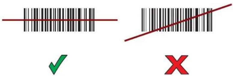
Figure3-7 Linear Scanner Aiming Pattern
- The scanner beeps and the LED turns green to indicate a successful decode.
- The captured data appears in the text field.
ReadingMagneticStripeCardswithScanning/MSRModule
Use the Scanning/MSR Module to read magnetic stripe cards.
- Ensure that MSR input is enabled in DataWedge and the cursor is in a text field.
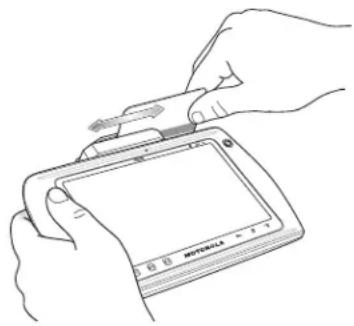
- Align the magnetic stripe on the card toward the display and swipe the card in either direction.
natural_image
Line drawing of hands inserting a device into a tablet (no text or symbols visible)Figure3-8 Swiping a Magnetic Stripe Card
- The captured data appears in the text field.
DataWedge
DataWedge is a utility that adds advanced bar code scanning capability to any application without writing code. It runs in the background and handles the interface to both built-in and attached bar code scanners. The captured bar code data is converted to keystrokes and sent to the target application as if it was typed on the keypad.
EnableDataWedge
To enable DataWedge:
- Touch > DataWedge. The DataWedge Profiles window appears.
- Touch > Settings.
- Touch the DataWedge enabled checkbox. A green checkmark appears in the checkbox indicating that DataWedge is enabled.
- Touch .
DisableDataWedge
To disable DataWedge:
- Touch > DataWedge. The DataWedge Profiles window appears.
- Touch > Settings.
- Touch the DataWedge enabled checkbox. The green checkmark disappears from the checkbox indicating that DataWedge is disabled.
- Touch .
Configuration
To configure DataWedge refer to the ET1 Enterprise Tablet Integrator Guide.
3-8ET1 Enterprise TabletUserGuide
CHAPTER4WLAN
Introduction
Wireless local area networks (WLANs) allow the ET1 to communicate wirelessly usually inside a building. Before using the ET1 on a WLAN, the facility must be set up with the required hardware to run the WLAN (sometimes known as infrastructure). The infrastructure and the ET1 must both be properly configured to enable this communication.
Refer to the documentation provided with the infrastructure (access points (APs), access ports, switches, Radius servers, etc.) for instructions on how to set up the infrastructure.
Once the infrastructure is set up to enforce the chosen WLAN security scheme, use the Wireless & networks settings configure the ET1 to match the security scheme.

NOTETurn off Wi-Fi when not using it, to extend the life of the battery.
The Status bar displays icons that indicate Wi-Fi network availability and Wi-Fi status. See Status Bar on page 2-2 for more information.
ScanandConnecttoaWi-FiNetwork
To set up WLAN on the ET1:
- Touch > Settings > Wireless & networks.
- Touch the Wi-Fi checkbox to turn Wi-Fi on.
- Touch Wi-Fi settings. The ET1 searches for WLANs in the area and lists them under Wi-Fi networks.
- Scroll through the list and select the desired WLAN network.
- For open networks, touch Connect or for secure networks enter the required password or other credentials then touch Connect. See the system administrator for more information.
The ET1 obtains a network address and other required information from the network using the dynamic host configuration protocol (DHCP) protocol. To configure the ET1 with a fixed internet protocol (IP) address, Refer to the ET1 Enterprise Tablet Integrator Guide.
- In the Wi-Fi setting field, Connected to network name appears indicating that the ET1 is connected to the WLAN.
CHAPTER5BLUETOOTH
Introduction
Bluetooth-equipped ET1 can communicate without wires, using frequency-hopping spread spectrum (FHSS) radio frequency (RF) to transmit and receive data in the 2.4 GHz Industry Scientific and Medical (ISM) band (802.15.1). Bluetooth wireless technology is specifically designed for short-range (10 meters (32.8 feet)) communication and low power consumption.
ET1s with Bluetooth capabilities can exchange information (e.g., files, appointments, and tasks) with other Bluetooth enabled devices such as printers, access points, and other mobile devices.
AdaptiveFrequencyHopping
Adaptive Frequency Hopping (AFH) is a method of avoiding fixed frequency interferers, and can be used with Bluetooth voice. All devices in the piconet (Bluetooth network) must be AFH-capable in order for AFH to work. There is no AFH when connecting and discovering devices. Avoid making Bluetooth connections and discoveries during critical 802.11b communications. AFH for Bluetooth consists of four main sections:
- Channel Classification - A method of detecting an interference on a channel-by-channel basis, or pre-defined channel mask.
- Link Management - Coordinates and distributes the AFH information to the rest of the Bluetooth network.
- Hop Sequence Modification - Avoids interference by selectively reducing the number of hopping channels.
• Channel Maintenance - A method for periodically re-evaluating the channels.
When AFH is enabled, the Bluetooth radio "hops around" (instead of through) the 802.11b high-rate channels. AFH coexistence allows Motorola Enterprise Tablets to operate in any infrastructure.
The Bluetooth radio in this ET1 operates as a Class 2 device power class. The maximum output power is 2.5 mW and the expected range is 10 meters (32.8 feet). A definition of ranges based on power class is difficult to obtain due to power and device differences, and whether one measures open space or closed office space.

NOTE It is not recommended to perform Bluetooth wireless technology inquiry when high rate 802.11b operation is required.
Security
The current Bluetooth specification defines security at the link level. Application-level security is not specified. This allows application developers to define security mechanisms tailored to their specific need. Link-level security occurs between devices, not users, while application-level security can be implemented on a per-user basis. The Bluetooth specification defines security algorithms and procedures needed to authenticate devices, and if needed, encrypt the data flowing on the link between the devices. Device authentication is a mandatory feature of Bluetooth while link encryption is optional.
Pairing of Bluetooth devices is accomplished by creating an initialization key that is used to authenticate the devices and create a link key for them. Entering a common personal identification number (PIN) in the devices being paired generates the initialization key. The PIN is never sent over the air. By default, the Bluetooth stack responds with no key when a key is requested (it is up to user to respond to the key request event).
Authentication of Bluetooth devices is based-upon a challenge-response transaction. Bluetooth allows for a PIN or passkey that is used to create other 128-bit keys used for security and encryption. The encryption key is derived from the link key used to authenticate the pairing devices. Also worthy of note is the limited range and fast frequency hopping of the Bluetooth radios that makes long-distance eavesdropping difficult.
Recommendations are:
• Perform pairing in a secure environment
- Keep PIN codes private and don't store the PIN codes in the ET1
• Implement application-level security.
The ET1 supports the following Bluetooth services:
- Generic Access Profile (GAP) - Must support both Initiator and Acceptor roles
• Service Discovery Protocol (SDP) - Supports both Local Device and Remote Device. - Serial Port Profile (SPP) - Supports both Device A and Device B roles.
• Human Interface Device Profile (HID) - Supports Host role.
BluetoothPowerStates
Suspend
When there is an active Bluetooth connection, the Bluetooth radio turns off.

NOTE If there is an active Bluetooth connection between the ET1 and another Bluetooth device and there is no data activity, the ET1 will time out. However, if the user presses the Power button on the ET1, the ET1 will suspend and upon receiving data from a remote Bluetooth device, the ET1 will wake from suspend mode. For example, Bluetooth scanner sending data to the ET1.
Resume
When the ET1 resumes, Bluetooth turns on if it was on prior to suspend.
AirplaneMode
When the ET1 is placed in Airplane Mode, the Bluetooth radio turns off. When Airplane mode is disabled, the Bluetooth radio returns to the prior state.
TurningBluetoothOnandOff
Turn off the Bluetooth radio to save power or if entering an area with radio restrictions (e.g., an airplane). When the radio is off, other Bluetooth devices cannot see or connect to the ET1. Turn on the Bluetooth radio to exchange information with other Bluetooth devices (within range). Communicate only with Bluetooth radios in close proximity.

NOTETo achieve the best battery life turn off radios not in use.
EnablingBluetooth
To enable Bluetooth:
- Touch > Settings > Wireless & networks.
- Touch the Bluetooth checkbox. A green check appears in the checkbox indicating that Bluetooth is enabled. The Bluetooth icon also appears in the Status bar.
- Touch .
DisablingBluetooth
To disable Bluetooth:
- Touch ≡ > Settings > Wireless & networks.
- Touch the Bluetooth checkbox. The green check disappears from the checkbox indicating that Bluetooth is disabled.
- Touch .
DiscoveringBluetoothDevice(s)
The ET1 can receive information from discovered devices without pairing. However, once paired, the ET1 and a paired device exchange information automatically when the Bluetooth radio is on.
To find Bluetooth devices in the area:
- Ensure that Bluetooth is enabled on both devices.
- Ensure that the Bluetooth device to discover is in discoverable mode.
- Ensure that the two devices are within 10 meters (32.8 feet) of one another.
-
Touch > Settings > Wireless & networks > Bluetooth settings.
-
Touch Scan for devices. The ET1 begins searching for discoverable Bluetooth devices in the area and displays them under Bluetooth devices.
- Scroll through the list and select a device. The Bluetooth pairing request dialog box appears.
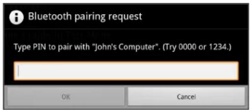
Figure5-1 Bluetooth Pairing - Enter PIN
- Enter a PIN in the text box and touch OK.
- Enter the same PIN on the other device.
- The Bluetooth device is added to the Bluetooth devices list and a trusted ("paired") connection is established.
ChangingtheBluetoothName
By default, the ET1 has a generic Bluetooth name that is visible to other devices when connected. To change the Bluetooth name:
- Touch ≡ > Settings > Wireless & networks > Bluetooth settings.
- If Bluetooth is not turned on, touch Bluetooth to turn it on.
- Touch Device name. The Device name dialog box appears.
- Enter a name and touch OK.
- Touch .
ConnecttoaBluetoothDevice
Once paired, connect to a Bluetooth device:
- Touch ≡ > Settings > Wireless & networks > Bluetooth settings.
- If Bluetooth is not turned on, touch Bluetooth to turn it on.
- In the Bluetooth devices list, touch and hold on a unconnected Bluetooth device until a menu appears.
- Touch Connect. When connected, the device is displayed as connected in the list.
SelectProfilesontheBluetoothDevice
Some Bluetooth devices have multiple profiles. To select a profile:
-
Touch ≡ > Settings > Wireless & networks > Bluetooth settings.
-
In the Bluetooth devices list, touch and hold on a Bluetooth device until a menu appears.
- Touch Options. The Connect to... screen appears.
-
Under Profiles, check or uncheck a profile to allow the ET1 to use that profile.
-
Touch .
DisconnectfromaBluetoothDevice
To disconnect from a Bluetooth device:
- Touch ≡ > Settings > Wireless & networks > Bluetooth settings.
- In the Bluetooth devices list, touch and hold on a device until a menu appears.
- Touch Disconnect.
- Touch .
UnpairaBluetoothDevice
To unpair a Bluetooth device and erase all pairing information:
- Touch ≡ > Settings > Wireless & networks > Bluetooth settings.
- In the Bluetooth devices list, touch and hold on a device until a menu appears.
-
Touch Unpair or Disconnect & unpair.
-
Touch .

5-6ET1 Enterprise TabletUserGuide
CHAPTER6PHOTOSANDVIDEOS
Introduction
This chapter provides information for taking photos and recording videos using the integrated digital cameras.

NOTEAn installed microSD card is required to store photos and videos.
Photos and videos are stored on the micro secure digital (SD) card. To copy photos and videos to a host computer, refer to the ET1 Enterprise Tablet Integrator Guide.
TakingPhotos

NOTE Camera settings are described in Camera Settings on page 6-2.
To take a photo:
- Touch
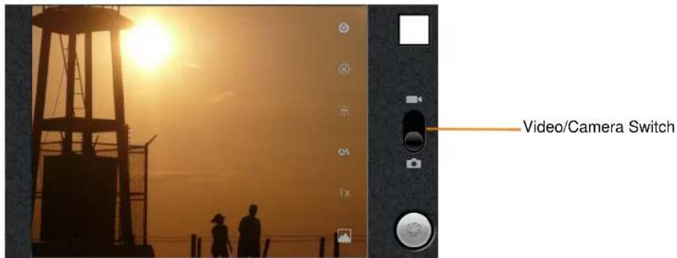
Figure6-1 Camera Mode
- If necessary, slide the Video/Camera Slider to the position.
- Adjust exposure, flash, and other settings using the camera settings. See Camera Settings on page 6-2 for more information.
- Select the front or back camera. Touch the Front 📁 or Back 📂 Select camera icon.
- Touch the Zoom icon 1x and then select a zoom level.
- Frame the subject on screen.
- Touch the on-screen Shutter button.
The camera brings the image into focus. When the image is in focus, the focus indicators in each corner turn green, the camera takes a photo and a shutter sound plays.

NOTE To disable the shutter sound, touch > Settings > Sounds and enable Silent mode.
Alternately, touch and hold the Shutter icon to focus first, before taking a photo; then release to take a focused photo.
The photo appears momentarily then displays as a thumbnail in the upper right corner.
- Touch the thumbnail to view the photo in Gallery. See Viewing Photos and Videos on page 6-6.
CameraSettings
Use the Camera application to control settings for photographs and videos.
- When in Camera mode, Camera settings are displayed on screen. Touch the icon for the settings to change. The settings open over the screen.
Rear-facingCamera
- Settings 📊ouch to open a scrolling list of settings:
- Focus mode - Touch to set autofocus features. Options: Auto (default), Infinity, Macro, Portrait, Hyperfocal or Continuous.
- Exposure - Touch to adjust the exposure settings. Options: +3, +2, +1, 0 (default), -1, -2 or -3.
- Scene mode - Touch to select a preset combination of camera settings designed for specific scenes. Options: Auto (default), Portrait, Landscape, Night, Night portrait, Theatre, Beach, Snow, Sunset, Steady photo, Sports or Party.
- Picture size - Touch to set the size (in pixels) of the photo. Options: 8M Pixels (default), 5M Pixels, 3M Pixels, 2M Pixels, VGA or QVGA.
• Picture quality - Touch to set the quality of the photo. Options: Super fine (default), Fine or Normal. - Color effect - Touch to select special effects. Options: None (default), Sepia, Negative, Solarize, Aqua, Red tint, Blue tint or Green tint.
- Camera settings - Touch Restore defaults to restore all camera settings to the default values.
- Store location - Include location information with each photo using the ET1 global positioning system (GPS).

Location not stored with photo (default).
- On Location stored with photo.
- White balance - Touch to select how Camera adjusts colors in different kinds of light, to achieve the most natural-looking colors.
• Auto - Adjust the white balance automatically (default).
• Incandescent - Adjust the white balance for incandescent lighting.
• Daylight - Adjust the white balance for daylight.
- Fluorescent - Adjust the white balance for fluorescent lighting.
- Cloudy - Adjust the white balance for a cloudy environment.
- Flash mode - Touch to set whether Rear-facing Camera relies on its light meter to decide whether a flash is necessary, or to turn it on or off for all shots.
• Auto - Camera adjusts flash automatically depending upon light meter.
- On Enable flash upon taking photo.
- Torch - Turn on flash.
- Off Disable flash (default).
- Zoom - Touch to zoom from 1x to 8x.
- Select camera - Touch to select the camera to use:
- Back - Rear facing camera (default).
- Front - Front facing camera.
Front-facingCamera
- Settings 📋ouch to open a scrolling list of settings:
- Scene mode - Touch to select a preset combination of camera settings designed for specific scenes. Options: Auto (default), Night and Night portrait.
• Photo size - Touch to set the size (in pixels) of the photo. Options: VGA (default) or QVGA.
• Picture quality - Touch to set the quality of the photo. Options: Super fine (default), Fine or Normal.
• Color effect - Touch to select special effects. Options: None (default), Mono, or Negative. - Camera settings - Touch Restore defaults to restore all camera settings to the default values.
- Store location - Include location information with each photo using the ET1 GPS.
- Location not stored with photo (default).
• One Location stored with photo.
• Zoom - Touch to zoom from 1x to 8x.
- Select camera - Touch to select the camera to use:
- Back - Rear-facing camera.
- Front - Front-facing camera.
RecordingVideos
To record a video:
- Touch > Camera.
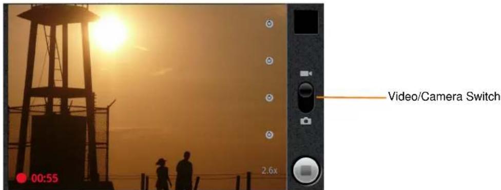
Figure6-2 Video Mode
- If necessary, slide the Video/Camera Slider to the Edition.
- Select the camera to use and adjust the quality, color effect, flash, and other settings.
- Point the lens and frame the scene.
- Touch to start recording.
The ET1 starts recording the video. The video time remaining appears in the bottom left of the screen. When less than a minute is left, the countdown turns red.
- Touch to end recording.

NOTEPreviously recorded video displays in the thumbnail at the top right.
- Touch the thumbnail to access the Gallery application.
VideoSettings
Rear-facingCamera
Video settings controls display on screen:
- Settings - Touch to open a scrolling list of settings:
• Color effect - Select a special effect. Options: None (default), Sepia, Negative, Solarize, Aqua, Red tint, Blue tint or Green tint.
- Camera settings -Touch Restore defaults to restore settings to the default values.
- White balance - Touch to select how the camera adjusts colors in different kinds of light, to achieve the most natural-looking colors for the video.
• Auto - Adjust the white balance automatically (default).
• Incandescent - Adjust the white balance for incandescent lighting.
• Daylight - Adjust the white balance for daylight.
- Fluorescent - Adjust the white balance for fluorescent lighting.
- Cloudy - Adjust the white balance for a cloudy environment.
- Flash mode - Select to illuminate the video by turning on the camera flash.
- On Enable flash.
- Off-Disable flash (default).
• Video quality - Touch to select video quality:
• High (30m) - High quality video 30 minutes maximum in length.
- Low (30m) - Low quality video 30 minutes maximum in length.
• MMS (Low, 30s) - Low quality video 30 seconds maximum in length for attaching to text messages.
- YouTube (High, 10m) - High quality video 10 minutes in length for posting to YouTube.
- Select camera - Touch to select the camera to use.
- Back - Rear-facing camera.
- Front - Front-facing camera.
Front-facingCamera
Video settings controls display on screen:
- Settings - Touch to open a scrolling list of settings:
• Color effect - Select a special effect. Options: None (default), Mono or Negative.
- Camera settings -Touch Restore defaults to restore settings to the default values.
- Color effect - Select a special effect. Options: None (default), Mono or Negative. - Camera settings -Touch Restore defaults to restore settings to the default values.
• Video quality - Touch to select video quality:
• High (30m) - High quality video 30 minutes maximum in length.
- Low (30m) - Low quality video 30 minutes maximum in length.
• MMS (Low, 30s) - Low quality video 30 seconds maximum in length for attaching to text messages.
- YouTube (High, 10m) - High quality video 10 minutes in length for posting to YouTube.
- High (30m) - High quality video 30 minutes maximum in length. - Low (30m) - Low quality video 30 minutes maximum in length. - MMS (Low, 30s) - Low quality video 30 seconds maximum in length for attaching to text messages. - YouTube (High, 10m) - High quality video 10 minutes in length for posting to YouTube.
- Select camera - Touch to select the camera to use.
- Back - Rear-facing camera.
- Front - Front-facing camera.
ViewingPhotosandVideos

NOTEThe ET1 supports the following image formats: jpeg, gif, png and bmp.
The ET1 supports the following video formats: H.263, H.264 and MPEG4 Simple Profile.
Use Gallery to:
• view photos
- play videos
• perform basic editing of photos
• set photos as wallpaper
• set photos as a contact photo
• share photos and videos.
To open the Gallery application:
- Touch > Gallery.
• In the Camera application, touch the thumbnail image at the top right.
• In the Camera application, touch ≡ > Gallery.
Gallery presents all photos and videos stored on the microSD card in albums.
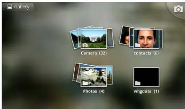
Figure6-3 Gallery - Albums
- Touch an album to open it and view its contents. The photos and videos in the album are displayed in chronological order. See Working with Albums on page 6-7.
- Peek into an album stack by touching it with two fingers and spreading them apart.
- Touch a photo or video in an album to view it.
- Touch the Gallery icon (top left corner) to return to the main Gallery screen.
WorkingwithAlbums
Albums are groups of images and videos in folders. Touch an album to open it. The photos and videos are listed in a chronologically ordered grid. The name of the album displays at the top of the screen.
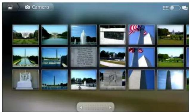
natural_image
Grid of 20 grayscale photos including U.S. Capitol Building, American flag sculpture, and memorial sites (no visible text or symbols)Figure6-4 Photos Inside an Album
Touch an arrow in the scroll tool at the bottom of the screen to scroll images across the screen or drag the scroll tool to the left or right to scroll more or less quickly. The date of the images in view appears to scroll by date.
Swipe left or right to view more images.
Changehowthecontentsofanalbumaredisplayed
View the photos and videos in an albums in a chronological grid or in stacks, sorted by the date and the location where they were taken. Switch album views using the Album View switch at the top right of the screen. Drag the Album View switch to the right to view the contents of the album in stacks.
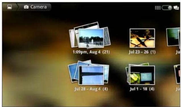
Figure6-5 Stack View
Drag the Album View switch to the left to view the album contents in a chronological grid.
In addition to working with whole albums and with individual photos, select one or more photos or videos in an album to work on them in batches.
- Open the album to view the photos and videos.
-
Touch twice.
-
Check or uncheck the items to work with. Uncheck all items checked by touching Deselect All at the top right of the window.
- Use the controls at the bottom of the screen to share, delete or get detail information.
ShareanAlbum
To share the entire contents of one or more albums:
- Touch > Gallery.
- Touch twice.
- Check or uncheck the albums to share.
- Touch Share. The Share menu opens. Touch the application to use to share the selected albums.
- Follow the instructions within the selected application.
GetAlbumInformation
To get information for an album:
- Touch > Gallery.
- Touch twice.
- Check an album.
- Touch More. The More menu displays. Touch Details.
DeleteanAlbum
To delete an album and its contents from the microSD card:
- Touch > Gallery.
- Touch twice.
- Check an albums to delete. Ensure that other albums are unchecked.
- Touch Delete. The Delete menu displays.
- Touch Confirm Delete to delete the album.
WorkingwithPhotos
Use Gallery to view photos on the microSD card and edit and share photos.
ViewandBrowsePhotos
To view a photo:
- Touch > Gallery.
- Touch an album to open it.
- Touch a photo.
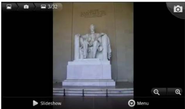
natural_image
Exterior view of a stone statue in a museum or memorial hall, with no visible text or symbols on the statue itself.Figure6-6 Photo Example
Drag left or right to view the next or previous photo in the album.
- Turn the ET1 to view the photo in upright (portrait) or sideways (landscape) orientation. The photo is displayed (but not saved) in the new orientation.
Touch the photo to view the controls.
Double-tap the screen to zoom in or pinch two fingers together or spread them apart to zoom in or out.
Drag the photo to view parts that are not in view.
Slideshow
To view a slideshow:
- Touch a photo to view the controls.
- Touch Slideshow. The photos in the album display.
- Touch a photo to end the slideshow.
RotateaPhoto
To rotate a photo:
- Touch a photo to view the controls.
- Touch Menu > More. The More menu appears.
- Touch Rotate Left or Rotate Right. The photo is automatically saved with the new orientation.
CropaPhoto
To crop a photo:
- Touch a photo to view the controls.
-
Touch Menu > More.
-
Touch Crop. The orange cropping tool appears.
-
Use the cropping tool to select the portion of the photo to crop.
-
Drag from the inside of the cropping tool to move it.
- Drag an edge of the cropping tool to resize it to any proportion.
- Drag a corner of the cropping tool to resize it with fixed proportions.
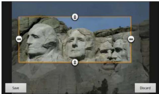
natural_image
Close-up of Mount Rushmore's carved stone face with visible portraits and inscriptions (no text extraction needed)Figure6-7 Cropping Tool
- Touch Save to save a copy of the cropped photo. The original version is retained.
UseaPhotoasaContactIcon
To use a photo as a contact icon:
- Touch the photo to view the controls.
- Touch Menu > More > Set as.
- Touch Contact icon. A list of contacts displays.
- Touch a contact.
- Touch the orange box and crop the photo accordingly.
- Touch Save.
SetaPhotoasWallpaper
To use a photo as wallpaper:
- Touch the photo to view the controls.
- Touch Menu > More > Set as.
- Touch Wallpaper. The orange cropping tool appears.
- Use the cropping tool to select the portion of the photo to crop.
• Drag from the inside of the cropping tool to move it.
- Drag an edge of the cropping tool to resize it to any proportion.
- Drag a corner of the cropping tool to resize it with fixed proportions.
- Touch Save.
GetPhotoInformation
To get information about a photo:
- Touch the photo to view the controls.
-
Touch Menu > More. The More menu appears.
-
Touch Details.
ShareaPhoto
To share a photo:
-
Touch a photo to view the controls.
-
Touch Menu > Share. The Share menu appears.
-
Touch the application to use to share the selected photo.
The application selected opens with the photo attached to a new message.
DeleteaPhoto
To delete a photo:
-
Touch a photo to view the controls.
-
Touch Menu > Delete. The Delete menu displays.
-
Touch Confirm Delete to delete the photo.
WorkingwithVideos
Use Gallery to play videos stored on the microSD card.
To play a video:
-
Touch > Gallery.
-
Open a Gallery album and touch a video.
-
The video plays.
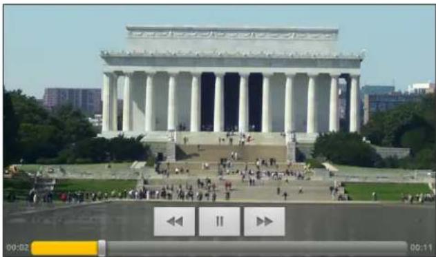
natural_image
Exterior view of a large neoclassical building with columns and steps, surrounded by greenery and people walking (no visible text or signage)Figure6-8 Playing Video
Touch the screen to view the playback controls.
SendVideoinanEmail
To send a video using Email:
-
While viewing an album, touch twice.
-
Check the videos to share.
-
Touch Share.
- In the Share menu, touch Email. Email opens with the video attached to a new message.
DeleteaVideo
To delete a video:
- While viewing an album, touch twice.
- Check the videos to delete.
- Touch Delete.
- Touch Confirm Delete.
CHAPTER7ACCESSORIES
Introduction
Table 7-1 lists the accessories available for the ET1.
Table7-1 ET1 Accessories
| AccessoryPartNumberDescription | ||
| Cradles | ||
| Single-slot USB Docking Cradle | DC1000-1000U Charges | the ET1 main battery and a spare battery. Synchronizes the ET1 with a host computer through a USB connection. |
| Four-slot Charge Only Docking Cradle | DC1000-4000C Charges | up to four ET1 devices. |
| Chargers | ||
| Four-slot Spare Battery Charger | SAC1000-4000C Charges | up to four ET1 battery packs. |
| Power Supply PWRS-1400 | 0-148C Provides power to | the Single-slot USB Docking cradle or the USB/Charge cable. 12 VDC, 4.16A. |
| Power Supply PWRS-1400 | 0-241R Provides power to | the Four-slot Charge Only Docking cradle or the Four-slot Battery Charger. 12 VDC, 9A. |
| Cables | ||
| USB Charge Cable 25-153 | 149-01R Provides power to | the ET1 and USB communication with a host computer. |
| DC Charge Cable 50-1600 | 2-029R Connects one power supply to the one Four-slot Charge Only Docking Cradle or the Four-slot Battery Charger. | |
| AccessoryPart Number | Description | |
| 2-way Charge Cable 25-15 | 3150-01R Connects one | power supply to:one Four-slot Charge Only Docking Cradle and one Four-slot Battery Chargertwo Four-slot Battery Chargers. |
| US AC Line Cord (3-wire) | 23844-00-00R Provides power to the power supplies. | |
| International AC line Cord | Provides power to the power supplies. Purchase separately. | |
| Miscellaneous | ||
| Spare 4620 mAh lithium-ion battery | BTRY-ET01EAB0EBTRY-ET01EAB0E-10 | Replacement 4620 mAh battery for ET1N0.Replacement 4620 mAh battery for ET1N0 (10-pack) |
| Spare 5640 mAh lithium-ion battery | BTRY-ET01EAB0HBTRY-ET01EAB0H-10 | Replacement 5640 mAh battery for ET1N0 and ET1N2.Replacement 5640 mAh battery for ET1N0 and ET1N2 (10-pack). |
| Handstrap SG-ET0123245 | 01R Adjustable and 360-degree rotatable handstrap that mounts on the back of the ET1 and provides secure option for holding the device. | |
| Scanning Module SCANMOD-ET1 Provides 2D bar code scanning. | ||
| Scanning/MSR Module MSRSCAN-ET1 Provides 2D bar code scanning and magnetic stripe card reading. | ||
| Protective Rubber Bezel | KT-161552-01R | Add additional protection for the ET1. |
Single-slotUSBDockingCradle
The Single-slot USB Docking cradle:
- Provides 12 VDC power for operating the ET1.
- Synchronizes information between the ET1 and a host computer. Refer to the ET1 Enterprise Tablet Integrator Guide for information on setting up a connection to a host computer.
- Charges the battery.
ChargingtheET1Battery
Connect the cradle to power. Insert the ET1 into the slot to begin charging.
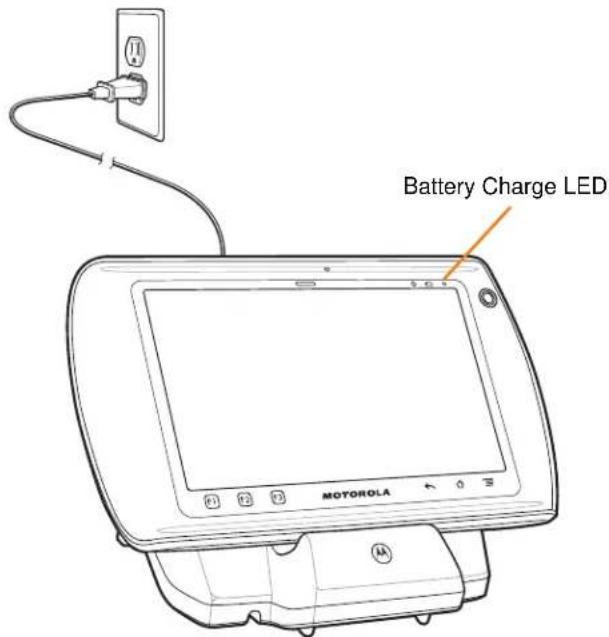
Figure7-1 ET1 Battery Charging
The ET1's charge Battery Charge light emitting diode (LED) indicates the status of the battery charging in the ET1. See Table 1-2 on page 1-7 for charging status indications. The battery fully charges in approximately six hours.
Charge batteries in temperatures from 0°C to 40°C (32°F to 104°F). Charging is intelligently controlled by the ET1. To accomplish this, for small periods of time, the ET1 or accessory alternately enables and disables battery charging to keep the battery at acceptable temperatures. The ET1 indicates when charging is disabled due to abnormal temperatures via Battery Charge LED. See Table 1-2 on page 1-7.
Communication
When the ET1 is connected to a host computer using the Single-slot USB Docking cradle, the ET1 appears as a Removable Disk on the host computer. Refer to the ET1 Enterprise Tablet Integrator Guide for more information.
Four-slotChargeOnlyDockingCradle
The Four-slot Charge Only Docking cradle:
• Provides 12 VDC power for operating the ET1.
• Simultaneously charges up to four ET1s.
Charging
Insert the ET1 into a slot to begin charging.
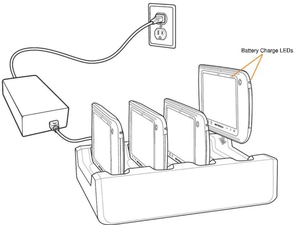
Figure7-2 ET1 Battery Charging
The ET1's Battery Charge LED shows the status of the battery charging in the ET1. See Table 1-2 on page 1-7 for charging status indications. The battery fully charges in approximately six hours.
ChargingTemperature
Charge batteries in temperatures from 0^ C to 40^ C ( 32^ F to 104^ F). Charging is intelligently controlled by the ET1. To accomplish this, for small periods of time, the ET1 or accessory alternately enables and disables battery charging to keep the battery at acceptable temperatures. The ET1 indicates when charging is disabled due to abnormal temperatures via the Battery Charge LED. See Table 1-2 on page 1-7.
Four-slotBatteryCharger
The Four-slot Battery Charger:
- Provides 12 VDC power for charging the batteries.
• Simultaneously charges up to four ET1 batteries.
To charge a spare battery:
- Connect the charger to a power source.
- Insert the battery into a battery charging well and gently press down on the battery to ensure proper contact.
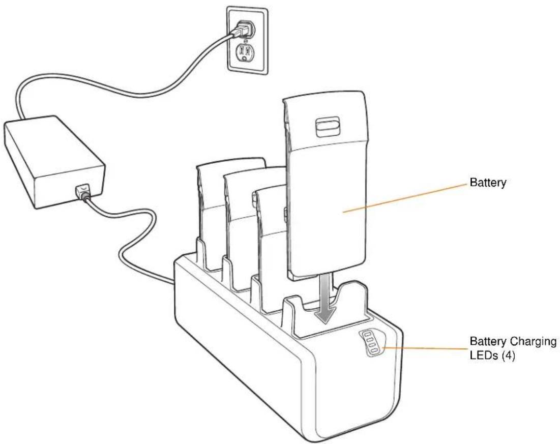
Figure7-3 Four Slot Battery Charger
The Four-slot Battery Charger has four amber Battery Charging LEDs, one for each battery charging well. See Table 7-2 for charging status indications. The battery fully charges in approximately six hours.
ChargingTemperature
Charge batteries in temperatures from 0^ C to 40^ C ( 32^ F to 104^ F). Charging is intelligently controlled by the ET1. To accomplish this, for small periods of time, the charger alternately enables and disables battery charging to keep the battery at acceptable temperatures. The charger indicates when charging is disabled due to abnormal temperatures via its LED. See Table 7-2.
Table7-2 Battery LED Charging Indicators
| LEDIndication | |
| Off No battery in slot. | Battery is not charging.Battery is not inserted correctly in the charger.Charger is not powered. |
| Slow Blinking Amber Battery is charging. | |
| Solid Green Charging complete. | |
| Fast Blinking Amber Charging error. | |
USB/ChargeCable
The USB/Charge cable:
- Provide the ET1 with operating and charging power.
- Synchronize information between the ET1 and a host computer.
Charging
To charge the ET1 battery:
- Connect the AC line cord to the power supply.
- Connect the power supply output connector to the input power port on the USB/Charge cable.
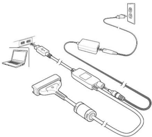
natural_image
Line drawing of a network device with cable, connectors, and power outlet (no text or symbols)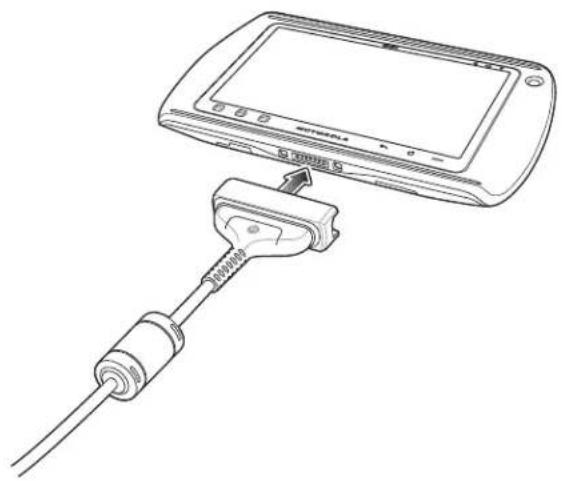
natural_image
Line drawing of a cable connector inserted into a device, showing cable type and cable end (no text or symbols)Figure7-4 USB/Charge Cable Setup
- Connect the USB/Charge Cable cup to the bottom of the ET1. Align the ends of the cup with the alignment marks on the ET1. The Battery Charge LED indicates the battery charging status. See Table 1-2 on page 1-7 for charging status indications. The battery charges in approximately six hours.
Charge batteries in temperatures from 0°C to 40°C (32°F to 104°F). Charging is intelligently controlled by the ET1. To accomplish this, for small periods of time, the ET1 alternately enables and disables battery charging to keep the battery at acceptable temperatures. The ET1 indicates when charging is disabled due to abnormal temperatures via the Battery Charge LED. See Table 1-2 on page 1-7.
Communication
When the ET1 is connected to a host computer using the USB/Charge cable, the ET1 appears as a Removable Disk on the host computer. Refer to the ET1 Enterprise Tablet Integrator Guide for more information.
HostUSBModule
The USB Host Module provides USB Host connection to a peripheral.
To connect to a peripheral:
- Lift the connector plug.
- Connect the microUSB connector to the USB Host Module.
- Connect the other end of the USB cable to the peripheral.
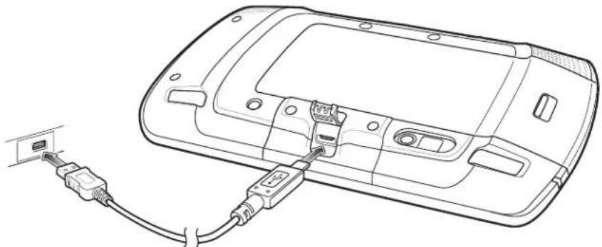
natural_image
Line drawing of a device with connectors and cable, no text or symbols presentFigure7-5 USB Host Module Connection
CHAPTER8MAINTENANCE& TROUBLESHOOTING
Introduction
This chapter includes instructions on cleaning and storing the ET1, and provides troubleshooting solutions for potential problems during ET1 operation.
MaintainingtheET1
For trouble-free service, observe the following tips when using the ET1:
- Do not scratch the screen of the ET1. When working with the ET1, use a finger or approved stylus or pen intended for use with a capacitive touch-sensitive screen. Never use an actual pen or pencil or other sharp object on the surface of the ET1 screen.
- The touch-sensitive screen of the ET1 is glass. Do not to drop the ET1 or subject it to strong impact.
- Protect the ET1 from temperature extremes. Do not leave it on the dashboard of a car on a hot day, and keep it away from heat sources.
- Do not store or use the ET1 in any location that is dusty, damp, or wet.
- Use a soft lens cloth to clean the ET1. If the surface of the ET1 screen becomes soiled, clean it with a soft cloth moistened with a diluted window-cleaning solution.
- Periodically replace the rechargeable battery to ensure maximum battery life and product performance. Battery life depends on individual usage patterns.
BatterySafetyGuidelines
- The area in which the units are charged should be clear of debris and combustible materials or chemicals. Particular care should be taken where the device is charged in a non commercial environment.
- Follow battery usage, storage, and charging guidelines found in this guide.
-
Improper battery use may result in a fire, explosion, or other hazard.
-
To charge the mobile device battery, the battery and charger temperatures must be between +32 °F and +104 °F (0 °C and +40 °C)
- Do not use incompatible batteries and chargers. Use of an incompatible battery or charger may present a risk of fire, explosion, leakage, or other hazard. If you have any questions about the compatibility of a battery or a charger, contact Motorola Solutions Global Customer Support Center.
- For devices that utilize a USB port as a charging source, the device shall only be connected to products that bear the USB-IF logo or have completed the USB-IF compliance program.
- To enable authentication of an approved battery, as required by IEEE1725 clause 10.2.1, all batteries will carry a Motorola hologram. Do not fit any battery without checking it has the Motorola authentication hologram.
- Do not disassemble or open, crush, bend or deform, puncture, or shred.
- Severe impact from dropping any battery-operated device on a hard surface could cause the battery to overheat.
- Do not short circuit a battery or allow metallic or conductive objects to contact the battery terminals.
- Do not modify or remanufacture, attempt to insert foreign objects into the battery, immerse or expose to water or other liquids, or expose to fire, explosion, or other hazard.
- Do not leave or store the equipment in or near areas that might get very hot, such as in a parked vehicle or near a radiator or other heat source. Do not place battery into a microwave oven or dryer.
- Battery usage by children should be supervised.
- Please follow local regulations to properly dispose of used re-chargeable batteries.
- Do not dispose of batteries in fire.
- In the event of a battery leak, do not allow the liquid to come in contact with the skin or eyes. If contact has been made, wash the affected area with large amounts of water and seek medical advice.
- If you suspect damage to your equipment or battery, contact Motorola Solutions Global Customer Support Center to arrange for inspection.
Cleaning

CAUTIONAlways wear eye protection.
Read warning label on compressed air and alcohol product before using.
If you have to use any other solution for medical reasons please contact Motorola for more information.

WARNING! Avoid exposing this product to contact with hot oil or other flammable liquids. If such exposure occurs, unplug the device and clean the product immediately in accordance with these guidelines.
ApprovedCleanserActiveIngredients
100% of the active ingredients in any cleaner must consist of one or some combination of the following: isopropyl alcohol, bleach/sodium hypochlorite, hydrogen peroxide or mild dish soap.
HarmfullIngredients
The following chemicals are known to damage the plastics on the ET1 and should not come in contact with the device: ammonia solutions, compounds of amines or ammonia; acetone; ketones; ethers; aromatic and chlorinated hydrocarbons; aqueous or alcoholic alkaline solutions; ethanolamine; toluene; trichloroethylene; benzene; carbolic acid and TB-lysoform.
CleaningInstructions
Do not apply liquid directly to the ET1. Dampen a soft cloth or use pre-moistened wipes. Do not wrap the device in the cloth or wipe, but gently wipe the unit. Be careful not to let liquid pool around the display window or other places. Allow the unit to air dry before use.
SpecialCleaningNotes
Many vinyl gloves contain phthalate additives, which are often not recommended for medical use and are known to be harmful to the housing of the ET1. The ET1 should not be handled while wearing vinyl gloves containing phthalates, or before hands are washed to remove contaminant residue after gloves are removed. If products containing any of the harmful ingredients listed above are used prior to handling the ET1, such as hand sanitizer that contain ethanolamine, hands must be completely dry before handling the ET1 to prevent damage to the plastics.
MaterialsRequired
- Alcohol wipes
- Lens tissue
• Cotton-tipped applicators - Isopropyl alcohol
- Can of compressed air with a tube.
CleaningtheET1
Housing
Using the alcohol wipes, wipe the housing including keys and in-between keys.
Display
The display can be wiped down with the alcohol wipes, but care should be taken not to allow any pooling of liquid around the edges of the display. Immediately dry the display with a soft, non-abrasive cloth to prevent streaking.
CameraWindow
Wipe the camera window periodically with a lens tissue or other material suitable for cleaning optical material such as eyeglasses.
Connector
- Remove the main battery from mobile computer. See Replacing the Battery on page 1-9.
-
Dip the cotton portion of the cotton-tipped applicator in isopropyl alcohol.
-
Rub the cotton portion of the cotton-tipped applicator back-and-forth across the connector on the bottom of the ET1. Do not leave any cotton residue on the connector.
- Repeat at least three times.
- Use the cotton-tipped applicator dipped in alcohol to remove any grease and dirt near the connector area.
- Use a dry cotton-tipped applicator and repeat steps 4 through 6.

CAUTION Do not point nozzle at yourself and others, ensure the nozzle or tube is away from your face.
- Spray compressed air on the connector area by pointing the tube/nozzle about 12 inch away from the surface.
- Inspect the area for any grease or dirt, repeat if required.
CleaningCradleConnectors
To clean the connectors on a cradle:
- Remove the DC power cable from the cradle.
- Dip the cotton portion of the cotton-tipped applicator in isopropyl alcohol.
- Rub the cotton portion of the cotton-tipped applicator along the pins of the connector. Slowly move the applicator back-and-forth from one side of the connector to the other. Do not leave any cotton residue on the connector.
- All sides of the connector should also be rubbed with the cotton-tipped applicator.

CAUTION Do not point nozzle at yourself and others, ensure the nozzle or tube is pointed away from your face.
- Spray compressed air in the connector area by pointing the tube/nozzle about 12 inch away from the surface.
-
Remove any lint left by the cotton-tipped applicator.
-
If grease and other dirt can be found on other areas of the cradle, use a lint-free cloth and alcohol to remove.
-
Allow at least 10 to 30 minutes (depending on ambient temperature and humidity) for the alcohol to air dry before applying power to cradle.
If the temperature is low and humidity is high, longer drying time is required. Warm temperature and dry humidity requires less drying time.
CleaningFrequency
The cleaning frequency is up to the customer's discretion due to the varied environments in which the mobile devices are used. They may be cleaned as frequently as required, but it is advisable to clean the camera window periodically when used in dirty environments to ensure optimum performance.
Troubleshooting
ET1EnterpriseTablet
Table8-1 Troubleshooting the ET1 Enterprise Tablet
| ProblemCauseSolution | ||
| When the user presses the Power button, the ET1 does not turn on. | Battery is completely discharged. | Re-charge or replace the battery. |
| Battery not installed properly. | Install the battery properly. SeeInstalling the Battery on page 1-5. | |
| Power button not held down long enough. | Press the Power button until the Battery Charge LED flashes three times. | |
| ET1 not responding. | Perform a hard reset. SeeResetting the ET1 on page 2-16. | |
| When the user presses the Power button the ET1 does not turn on but the Decode LED blinks yellow. | Battery charge level is very low. | Re-charge or replace the battery. |
| Battery did not charge. | Battery failed. Replace battery. If the ET1 still does not operate, perform a hardware reset. SeeResetting the ET1 on page 2-16. | |
| ET1 was removed from cradle while battery was charging. | Insert ET1 in cradle. The 4620 mAh battery fully charges in less than six hours. | |
| Extreme battery temperature. | Battery does not charge if ambient temperature is below 0°C (32°F) or above 40°C (104°F). | |
| During data communication, no data transmitted, or transmitted data was incomplete. | ET1 removed from cradle or disconnected from host computer during communication. | Replace the ET1 in the cradle, or reattach the communication cable and re-transmit. |
| Incorrect cable configuration. | See the system administrator. | |
| No sound. Volume setting is low or turned off. | Adjust the volume. | |
| ET1 turns off. | ET1 is inactive. | The display turns off after a period of inactivity. Set this period to 15 seconds, 30 seconds, 1, 2, 10, or 30 minutes. |
| Battery is depleted. | Recharge or replace the battery. | |
| A message appears stating not enough storage memory. | Too many applications installed on the ET1. | Remove user-installed applications on the ET1 to recover memory. Select >Settings >Applications >Manage Applications. Select the unused programs and touch Uninstall. |
| The ET1 does not decode when reading bar code. | DataWedge is not enable. | Ensure that DataWedge is enabled and configured properly. Refer to the ET1 Enterprise Tablet Integrator Guide for more information. |
| Unreadable bar code. | Ensure the symbol is not defaced. | |
| Distance between the ET1 and bar code is incorrect. | Place the ET1 within proper scanning range. | |
| ET1 is not programmed for the bar code type. | Program the ET1 to accept the type of bar code being scanned. Refer to the ET1 Enterprise Tablet Integrator Guide for DataWedge configuration. | |
| ET1 is not programmed to generate a beep. | If the ET1 does not beep on a good decode, set the application to generate a beep on good decode. | |
| ET1 does not read magnetic stripe card | Magnetic stripe on card is facing the wrong way. | Ensure that magnetic stripe card is oriented correctly. Magnetic stripe of card should be facing the display. |
| MSR reading is not enabled. | Program the ET1 to accept MSR input. Refer to the ET1 Enterprise Tablet Integrator Guide for DataWedge configuration. | |
| ET1 cannot find any Bluetooth devices nearby. | Too far from other Bluetooth devices. | Move closer to the other Bluetooth device(s), within a range of 10 meters (30 feet). |
| The Bluetooth device(s) nearby are not turned on. | Turn on the Bluetooth device(s) to find. | |
| The Bluetooth device(s) are not in discoverable mode. | Set the Bluetooth device(s) to discoverable mode. If needed, refer to the device's user documentation for help. | |
Single-slotUSBDockingCradle
Table8-2 Troubleshooting the Single-slot USB Docking Cradle
| SymptomPossibleCauseAction | ||
| ET1 battery is not charging. | ET1 was removed from cradle or cradle was unplugged from AC power too soon. | Ensure cradle is receiving power. Ensure ET1 is seated correctly. Confirm the battery is charging. The 4620 mAh battery fully charges in less than six hours. |
| Battery is faulty. Verify | that other batteries charge properly. If so, replace the faulty battery. | |
| The ET1 is not fully seated in the cradle. | Remove and re-insert the ET1 into the cradle, ensuring it is firmly seated. | |
| Extreme battery temperature. | Battery does not charge if ambient temperature is below 0°C (32°F) or above 40°C (104°F). | |
| During data communication, no data transmits, or transmitted data was incomplete. | ET1 removed from cradle during communications. | Replace ET1 in cradle and retransmit. |
| Communication software is not installed or configured properly. | Perform setup as described in the ET1 Enterprise Tablet Integrator Guide. | |
Four-slotChargeOnlyDockingCradle
Table8-3 Troubleshooting the Four-slot Charge only Docking Cradle
| SymptomCauseSolution | ||
| Battery is not charging. ET1 removed from the cradle too soon. | Replace the ET1 in the cradle. The 4620 mAh battery fully charges in less than six hours. Tap > Settings > About device > Status to view battery status. | |
| Battery is faulty. Verify that other batteries charge properly. If so, replace the faulty battery. | ||
| ET1 is not inserted correctly in the cradle. Remove the ET1 and reinsert it correctly. Verify charging is active. Tap > Settings > About device > Status to view battery status. | ||
| Ambient temperature of the cradle is too warm. Move the cradle to an area where the ambient temperature is between 0°C (32°F) and 35°C (95°F). | ||
Four-slotBatteryCharger
Table8-4 Troubleshooting The Four-slot Battery Charger
| SymptomPossibleCauseAction | |||
| Battery not charging. Battery was removed from the charger or charger was unplugged from AC power too soon. | Re-insert the battery in the charger or re-connect the charger's power supply. The 4620 mAh battery fully charges in less than six hours. | ||
| Battery is faulty. Verify that other batteries charge properly. If so, replace the faulty battery. | |||
| Battery contacts not connected to charger. | Verify that the battery is seated in the battery well correctly with the contacts facing down. | ||
USB/ChargeCable
Table8-5 Troubleshooting the USB/Charge Cable
| SymptomPossibleCauseAction | ||
| Battery is not charging. ET1 was disconnected from AC power too soon. | Connect the power cable correctly. Confirm main battery is charging under Settings > About device > Status. The 4620 mAh battery fully charges in less than six hours. | |
| Battery is faulty. Verify that other batteries charge properly. If so, replace the faulty battery. | ||
| The ET1 is not connected to power. Detach and re-attach the power cable to the ET1, ensuring it is firmly connected. | ||
| During data communication, no data transmits, or transmitted data was incomplete. | Cable was disconnected from ET1 during communications. | Re-attach the cable and retransmit. |
| Incorrect cable configuration. | See the system administrator. | |
| Communication software is not installed or configured properly. | Perform setup as described in the ET1 Enterprise Tablet Integrator Guide. | |
APPENDIXATECHNICAL SPECIFICATIONS
ET1TechnicalSpecifications
The following tables summarize the ET1's intended operating environment and technical hardware specifications.
TableA-1 ET1 Technical Specifications
| ItemDescription | |
| Physical Characteristics | |
| Dimensions(with USB Host Expansion Module) | Height: 130.5 mm (5.14 in.)Width: 224 mm (8.82 in.)Depth: 25 mm (0.98 in.) |
| Weight ET1N0: 630 g (22.4 oz.) | ET1N2: 706 g (24.9 oz.) |
| Display | 7 in. capacitive; 1024 x 600; 350 nit; Corning® Gorilla® Glass. |
| Touch Panel Capacitive multi-touch | |
| Backlight LED backlight | |
| Battery Pack Rechargeable Lithium | lon 3.7V, 4620 mAh or 5640 mAh Smart battery. |
| Backup Battery NiMH battery (rechargeable) | 15 mAh 3.6 V (not user accessible). |
| Expansion Slot User accessible microSD slot, up to 32 GB. | |
| Connectivity Two USB interfaces: | one USB 2.0 OTG connector (docking connector) and one USB 2.0 Host connector (expansion module port); HDMI output; communication via cradle and expansion ports; USB 2.0 host via expansion module. |
| Notification LED, audio and vibration. | |
| Keypad Options | On-screen keyboard. |
| Item | Description |
| Audio Stereo speakers, microphone and headset connector (mono, 2.5 mm jack with microphone.) | |
| Performance Characteristics | |
| CPU Texas Instruments OMAP 4430 @ 1 GHz. | |
| Operating System Android-based A | SOP 2.3. |
| Memory 1GB RAM, 4 GB Flash plus 4 GB microSD; user accessible microsD card slot (supports up to 32 GB). | |
| Output Power (USB) Docking Con | ector: 5 VDC @ 500 mA max.Expansion Module: 5 VDC @ 500 mA max. |
| User Environment | |
| Operating Temperature 0°C to 50°C (32°F to 122°F) | |
| Storage Temperature -40°C to 70°C (-40°F to 158°F) | |
| Charging Temperature 0°C to 40°C (32°F to 104°F) | |
| Humidity 10% to 95% RH non-condensing | |
| Drop Specification Multiple 1.2 m (4 ft.) drops per MIL-STD 810G specifications. | |
| Electrostatic Discharge (ESD) +/-15kVdc air discharge, +/-8kVdc direct discharge, +/-8kVdc indirect discharge | |
| Sealing IP54 | |
| Wireless LAN Data Communications | |
| Wireless Local Area Network (WLAN) radio | IEEE® 802.11a/b/g/n with internal antenna |
| Data Rates Supported | 1, 2, 5.5, 6, 9, 11, 12, 18, 24, 36, 48, and 54 Mbps.Note that 802.11n data rates may be higher. |
| Operating Channels | Chan 36-165 (5180 – 5825 MHz), Chan 1-13 (2412-2472 MHz); actual operating channels/frequencies depend on regulatory rules and certification agency |
| Security | Security Modes: Legacy, WPA and WPA2Encryption: WEP (40 and 128 bit), TKIP and AESAuthentication: TLS, TTLS (MS-CHAP), TTLS (MS-CHAP v2), TTLS (CHAP), TTLS (PAP), PEAP-TLS, PEAP (MS-CHAP v2), EAP -FAST-TLS, EAP-FAST (MS-CHAP v2). |
| Spreading Technique Direct Sequence | ance Spread Spectrum (DSSS) and Orthogonal Frequency Division Multiplexing (OFDM) |
| Wireless PAN Data and Voice Communications | |
| Bluetooth | Class II, v 2.1 with EDR; integrated antenna. |
| Wireless WAN Data | |
| Wireless Wide Area Network Data | only: 3.5G GSM HSDPA and 3.5G CDMA-EVDO Rev A. |
| Data Capture | |
| Rear-facing Camera For bar code | scanning and image capture: 8 MP auto-focus camera with user controllable LED flash, illumination and aiming; captures 1D and 2D bar codes, photographs, video, signatures and documents. |
| Front-facing Camera VGA camera | optimized for video collaboration and low lighting condition. |
| Scanning Module For bar code scanning. | |
| Scanning/MSR Module For bar code scanning and reading magnetic stripe cards. | |
| Sensors | |
| Gyroscope Maintains orientation based on principles of conservation of angular momentum. | |
| Motion Sensor 3-axis accelerometer that enables motion sensing applications for dynamic screen orientation and power management. | |
| Ambient Light Sensor Automatically adjusts display brightness. | |
| Electronic Compass Independent - does not depend on GPS. | |
| Scanning / Scanning/MSR Module (SE4500-DL) Specifications | |
| Field of View Horizontal - 39.2° | Vertical - 25.4° |
| Optical Resolution | WVGA 752 H x 480 V pixels (gray scale) |
| Roll | 360° |
| Pitch Angle | +/- 60° from normal |
| Skew Tolerance | +/- 60° from normal |
| Ambient Light | Outdoor: 9000 ft. candles (96,900 lux) |
| Focal Distance | From center of exit window: 18.5 cm (7.3 in.) |
| Aiming Element (VLD) | 655 nm +/- 10 nm |
| Illumination Element (LED) | 625 nm +/- 5 nm |
TableA-2 Data Capture Options
| ItemDescription | |||
| 1D Bar Codes Code 39 UPC | A UPCE | ||
| EAN-13 EAN-8 Code 128 | |||
| Code 93 Code 11 Web Code | |||
| MSI Discrete 2 of 5 Interleaved 2 of 5 | |||
| Codabar | UPCE1 | Trioptic Code 39 | |
| Chinese 2 of 5 | Korean 2 of 5 | GS1 DataBar | |
| GS1 DataBar Limited | GS1 DataBar Expanded | TLC 39 | |
| Matrix 2 of 5 | |||
| 2D Bar Codes PDF | Micro PDF | Composite C | |
| Composite AB | Data Matrix | QR Code | |
| Micro QR | Aztec | US Planet | |
| US Postnet | UK Postal | Japan Postal | |
| Australian Postal | Dutch Postal | Maxicode | |
| Canadian Postal | US4State | US4State FICS | |
ET1AccessorySpecifications
Single-slotUSBDockingCradle
TableA-3 Single-slot USB Docking Cradle Technical Specifications
| Feature | Description |
| Dimensions | Height: 61.62 mm (2.43 in.)Width:151.9 mm (5.98 in.)Depth: 138.39 mm (5.45 in.) |
| Weight | 620 g (21.87 oz) |
| Input Voltage | 12 VDC |
| Power Consumption (with ET1) | 24 watts |
| Interface | USB |
| Operating Temperature | 0°C to 50°C (32°F to 122°F) |
| Storage Temperature | -40°C to 70°C (-40°F to 158°F) |
| Charging Temperature | 0°C to 40°C (32°F to 104°F) |
| Humidity | 5% to 95% non-condensing |
| Drop | 76.2 cm (30.0 in.) drops to vinyl tiled concrete at room temperature |
| Electrostatic Discharge (ESD) | +/- 15 kV air+/- 8 kV contact |
Four-slotChargeOnlyDockingCradle
TableA-4 Four-slot Charge Only Docking Cradle Technical Specifications
| FeatureDescription | |
| Dimensions Height: 83.45 mm (3.29 in.) | Width: 243.28 mm (9.58 in.)Depth: 330.17 mm (13.00 in.) |
| Weight 1.678 kg (3.70 lbs.) | |
| Input Voltage 12 VDC | |
| Power Consumption (with four ET1s 50 watts | |
| Operating Temperature 0°C to 50°C (32°F to 122°F) | |
| Storage Temperature -40°C to 70°C (-40°F to 158°F) | |
| Charging Temperature 0°C to 40°C (32°F to 104°F) | |
| Humidity 5% to 95% non-condensing | |
| Drop | 76.2 cm (30.0 in.) drops to vinyl tiled concrete at room temperature |
| Electrostatic Discharge (ESD) | +/- 15 kV air+/- 8 kV contact |
Four-slotBatteryCharger
TableA-5 Four-slot Battery Charger Technical Specifications
| Feature | Description |
| Dimensions | Height:110.62 mm (4.36 in.)Width:100.88 mm (3.97 in.)Depth: 245.15 mm (9.65) |
| Weight | 580 g (20.46 in.) |
| Input Voltage | 12 VDC |
| Power Consumption (with four batteries) | 25 watts |
| Operating Temperature | 0°C to 40°C (32°F to 104°F) |
| Storage Temperature | -40°C to 70°C (-40°F to 158°F) |
| Charging Temperature | 0°C to 40°C (32°F to 104°F) |
| Humidity | 5% to 95% non-condensing |
| Drop | 76.2 cm (30.0 in.) drops to vinyl tiled concrete at room temperature |
| Electrostatic Discharge (ESD) | +/- 15 kV air+/- 8 kV contact |
USB/ChargeCable
TableA-6 USB/Charge Cable Technical Specifications
| FeatureDescription | |
| Length 160.0 cm (63.0 in.) | |
| Operating Temperature -10°C to 50°C (14°F to 122°F) | |
| Storage Temperature -40°C to 70°C (-40°F to 158°F) | |
| Humidity 10% to 95% non-condensing | |
| Electrostatic Discharge (ESD) +/- 15 kV air | +/- 8 kV contact |
GLOSSARY
A
API. (Application Programming Interface) An interface by means of which one software component communicates with or controls another. Usually used to refer to services provided by one software component to another, usually via software interrupts or function calls
AFH. Adaptive Frequency Hopping.
B
Bar Code. A pattern of variable-width bars and spaces which represents numeric or alphanumeric data in machine-readable form. The general format of a bar code symbol consists of a leading margin, start character, data or message character, check character (if any), stop character, and trailing margin. Within this framework, each recognizable symbology uses its own unique format. See Symbology.
Bit. Binary digit. One bit is the basic unit of binary information. Generally, eight consecutive bits compose one byte of data. The pattern of 0 and 1 values within the byte determines its meaning.
Bits per Second (bps). Bits transmitted or received.
Bluetooth. A wireless protocol utilizing short-range communications technology facilitating data transmission over short distances.
boot or boot-up. The process a computer goes through when it starts. During boot-up, the computer can run self-diagnostic tests and configure hardware and software.
Byte. On an addressable boundary, eight adjacent binary digits (0 and 1) combined in a pattern to represent a specific character or numeric value. Bits are numbered from the right, 0 through 7, with bit 0 the low-order bit. One byte in memory is used to store one ASCII character.
C
CDRH. Center for Devices and Radiological Health. A federal agency responsible for regulating laser product safety. This agency specifies various laser operation classes based on power output during operation.
CDRH Class 1. This is the lowest power CDRH laser classification. This class is considered intrinsically safe, even if all laser output were directed into the eye's pupil. There are no special operating procedures for this class.
CDRH Class 2. No additional software mechanisms are needed to conform to this limit. Laser operation in this class poses no danger for unintentional direct human exposure.
Character. A pattern of bars and spaces which either directly represents data or indicates a control function, such as a number, letter, punctuation mark, or communications control contained in a message.
Codabar. A discrete self-checking code with a character set consisting of digits 0 to 9 and six additional characters: (“-”, “\$”, “:”, “/”, “,” and “+”).
Code 128. A high density symbology which allows the controller to encode all 128 ASCII characters without adding extra symbol elements.
Code 3 of 9 (Code 39). A versatile and widely used alphanumeric bar code symbology with a set of 43 character types, including all uppercase letters, numerals from 0 to 9 and 7 special characters (“-”, “.”, “/”, “+”, “%”, “\$” and space). The code name is derived from the fact that 3 of 9 elements representing a character are wide, while the remaining 6 are narrow.
Code 93. An industrial symbology compatible with Code 39 but offering a full character ASCII set and a higher coding density than Code 39.
COM port. Communication port; ports are identified by number, e.g., COM1, COM2.
Cradle. A cradle is used for charging the terminal battery and for communicating with a host computer, and provides a storage place for the terminal when not in use.
D
Decode. To recognize a bar code symbology (e.g., UPC/EAN) and then analyze the content of the specific bar code scanned.
Decode Algorithm. A decoding scheme that converts pulse widths into data representation of the letters or numbers encoded within a bar code symbol.
Decryption. Decryption is the decoding and unscrambling of received encrypted data. Also see, Encryption and Key.
Depth of Field. The range between minimum and maximum distances at which a scanner can read a symbol with a certain minimum element width.
Discrete 2 of 5. A binary bar code symbology representing each character by a group of five bars, two of which are wide. The location of wide bars in the group determines which character is encoded; spaces are insignificant. Only numeric characters (0 to 9) and START/STOP characters may be encoded.
E
EAN. European Article Number. This European/International version of the UPC provides its own coding format and symbology standards. Element dimensions are specified metrically. EAN is used primarily in retail.
EMDK. Enterprise Mobility Developer's Kit.
Encryption. Encryption is the conversion of data into a form that cannot be easily understood by unauthorized people. Also see, Decryption and Key.
Enterprise Tablet. In this text, enterprise tablet refers to the ET1. It can be set up to run as a stand-alone device, or it can be set up to communicate with a network, using wireless radio technology.
ESD. Electro-Static Discharge
F
File Transfer Protocol (FTP). A TCP/IP application protocol governing file transfer via network or telephone lines. See TCP/IP.
Flash Memory. Flash memory is nonvolatile, semi-permanent storage that can be electronically erased in the circuit and reprogrammed.
FHSS (Frequency Hopping Spread Spectrum). A method of transmitting radio signals by rapidly switching a carrier among many frequency channels, using a pseudorandom sequence known to both transmitter and receiver.
H
Hz. Hertz; A unit of frequency equal to one cycle per second.
Host Computer. A computer that serves other terminals in a network, providing such services as computation, database access, supervisory programs and network control.
|
IEC. International Electrotechnical Commission. This international agency regulates laser safety by specifying various laser operation classes based on power output during operation.
IEC (825) Class 1. This is the lowest power IEC laser classification. Conformity is ensured through a software restriction of 120 seconds of laser operation within any 1000 second window and an automatic laser shutdown if the scanner's oscillating mirror fails.
IEEE Address. See MAC Address.
Input/Output Ports. I/O ports are primarily dedicated to passing information into or out of the terminal's memory. ET1 mobile computers include USB ports.
Interleaved 2 of 5. A binary bar code symbology representing character pairs in groups of five bars and five interleaved spaces. Interleaving provides for greater information density. The location of wide elements (bar/spaces) within each group determines which characters are encoded. This continuous code type uses no intercharacter spaces. Only numeric (0 to 9) and START/STOP characters may be encoded.
Internet Protocol Address. See IP.
I/O Ports. The connection between two devices, defined by common physical characteristics, signal characteristics, and signal meanings. Types of interfaces include RS-232 and USB.
IP. Internet Protocol. The IP part of the TCP/IP communications protocol. IP implements the network layer (layer 3) of the protocol, which contains a network address and is used to route a message to a different network or subnetwork. IP accepts "packets" from the layer 4 transport protocol (TCP or UDP), adds its own header to it and delivers a "datagram" to the layer 2 data link protocol. It may also break the packet into fragments to support the maximum transmission unit (MTU) of the network.
IP Address. (Internet Protocol address) The address of a computer attached to an IP network. Every client and server station must have a unique IP address. A 32-bit address used by a computer on a IP network. Client workstations have either a permanent address or one that is dynamically assigned to them each session. IP addresses are written as four sets of numbers separated by periods; for example, 204.171.64.2.
IPX/SPX. Internet Package Exchange/Sequential Packet Exchange. A communications protocol for Novell. IPX is Novell's Layer 3 protocol, similar to XNS and IP, and used in NetWare networks. SPX is Novell's version of the Xerox SPP protocol.
ISM. Industry Scientific and Medical
K
Key. A key is the specific code used by the algorithm to encrypt or decrypt the data. Also see, Encryption and Decryption.
L
LASER. Light Amplification by Stimulated Emission of Radiation. The laser is an intense light source. Light from a laser is all the same frequency, unlike the output of an incandescent bulb. Laser light is typically coherent and has a high energy density.
laser scanner. A type of bar code reader that uses a beam of laser light.
LED Indicator. A semiconductor diode (LED - Light Emitting Diode) used as an indicator, often in digital displays. The semiconductor uses applied voltage to produce light of a certain frequency determined by the semiconductor's particular chemical composition.
Light Emitting Diode. See LED.
Liquid Crystal Display (LCD). A display that uses liquid crystal sealed between two glass plates. The crystals are excited by precise electrical charges, causing them to reflect light outside according to their bias. They use little electricity and react relatively quickly. They require external light to reflect their information to the user.
M
MDN. Mobile Directory Number. The directory listing telephone number that is dialed (generally using POTS) to reach a mobile unit. The MDN is usually associated with a MIN in a cellular telephone -- in the US and Canada, the MDN and MIN are the same value for voice cellular users. International roaming considerations often result in the MDN being different from the MIN.
MIN. Mobile Identification Number. The unique account number associated with a cellular device. It is broadcast by the cellular device when accessing the cellular system.
N
Nominal. The exact (or ideal) intended value for a specified parameter. Tolerances are specified as positive and negative deviations from this value.
NVM. Non-Volatile Memory.
O
Open System Authentication. Open System authentication is a null authentication algorithm.
P
PAN. Personal Area Network. Using Bluetooth wireless technology, PANs enable devices to communicate wirelessly. Generally, a wireless PAN consists of a dynamic group of less than 255 devices that communicate within about a 33-foot range. Only devices within this limited area typically participate in the network.
PING. (Packet Internet Groper) An Internet utility used to determine whether a particular IP address is online. It is used to test and debug a network by sending out a packet and waiting for a response.
R
RAM. Random Access Memory. Data in RAM can be accessed in random order, and quickly written and read.
RF. Radio Frequency.
ROM. Read-Only Memory. Data stored in ROM cannot be changed or removed.
Router. A device that connects networks and supports the required protocols for packet filtering. Routers are typically used to extend the range of cabling and to organize the topology of a network into subnets. See Subnet.
s
Scanner. An electronic device used to scan bar code symbols and produce a digitized pattern that corresponds to the bars and spaces of the symbol. Its three main components are: 1) Light source (laser or photoelectric cell) - illuminates a bar code,; 2) Photodetector - registers the difference in reflected light (more light reflected from spaces); 3) Signal conditioning circuit - transforms optical detector output into a digitized bar pattern.
SDK. Software Development Kit
Shared Key. Shared Key authentication is an algorithm where both the AP and the MU share an authentication key.
SID. System Identification code. An identifier issued by the FCC for each market. It is also broadcast by the cellular carriers to allow cellular devices to distinguish between the home and roaming service.
Soft Reset. See Warm Boot.
Space. The lighter element of a bar code formed by the background between bars.
Specular Reflection. The mirror-like direct reflection of light from a surface, which can cause difficulty decoding a bar code.
Start/Stop Character. A pattern of bars and spaces that provides the scanner with start and stop reading instructions and scanning direction. The start and stop characters are normally to the left and right margins of a horizontal code.
Subnet. A subset of nodes on a network that are serviced by the same router. See Router.
Subnet Mask. A 32-bit number used to separate the network and host sections of an IP address. A custom subnet mask subdivides an IP network into smaller subsections. The mask is a binary pattern that is matched up with the IP address to turn part of the host ID address field into a field for subnets. Default is often 255.255.255.0.
Substrate. A foundation material on which a substance or image is placed.
Symbol. A scannable unit that encodes data within the conventions of a certain symbology, usually including start/stop characters, quiet zones, data characters and check characters.
Symbol Aspect Ratio. The ratio of symbol height to symbol width.
Symbol Height. The distance between the outside edges of the quiet zones of the first row and the last row.
Symbol Length. Length of symbol measured from the beginning of the quiet zone (margin) adjacent to the start character to the end of the quiet zone (margin) adjacent to a stop character.
Symbology. The structural rules and conventions for representing data within a particular bar code type (e.g. UPC/EAN, Code 39, PDF417, etc.).
T
TCP/IP. (Transmission Control Protocol/Internet Protocol) A communications protocol used to internetwork dissimilar systems. This standard is the protocol of the Internet and has become the global standard for communications. TCP provides transport functions, which ensures that the total amount of bytes sent is received correctly at the other end. UDP is an alternate transport that does not guarantee delivery. It is widely used for real-time voice and video transmissions where erroneous packets are not retransmitted. IP provides the routing mechanism. TCP/IP is a routable protocol, which means that all messages contain not only the address of the destination station, but the address of a destination network. This allows TCP/IP messages to be sent to multiple networks within an organization or around the world, hence its use in the worldwide Internet. Every client and server in a TCP/IP network requires an IP address, which is either permanently assigned or dynamically assigned at startup.
Telnet. A terminal emulation protocol commonly used on the Internet and TCP/IP-based networks. It allows a user at a terminal or computer to log onto a remote device and run a program.
TFTP. (Trivial File Transfer Protocol) A version of the TCP/IP FTP (File Transfer Protocol) protocol that has no directory or password capability. It is the protocol used for upgrading firmware, downloading software and remote booting of diskless devices.
Tolerance. Allowable deviation from the nominal bar or space width.
Transmission Control Protocol/Internet Protocol. See TCP/IP.
Trivial File Transfer Protocol. See TFTP.
U
UDP. User Datagram Protocol. A protocol within the IP protocol suite that is used in place of TCP when a reliable delivery is not required. For example, UDP is used for real-time audio and video traffic where lost packets are simply ignored, because there is no time to retransmit. If UDP is used and a reliable delivery is required, packet sequence checking and error notification must be written into the applications.
UPC. Universal Product Code. A relatively complex numeric symbology. Each character consists of two bars and two spaces, each of which is any of four widths. The standard symbology for retail food packages in the United States.
V
Visible Laser Diode (VLD). A solid state device which produces visible laser light.
Glossary-8ET1 Enterprise TabletUserGuide
INDEX
Numerics
1-D bar codes 3-2
2-D bar codes 3-1
2-way charge cable 7-2
A
AC line cord 7-2
accessories 2-way charge cable 7-2
four-slot charge only docking cradle .....7-1, 7-4
four-slot spare battery charger .....7-1, 7-5
single-slot USB docking cradle ..... 7-1, 7-3
spare battery 7-2
specifications A-4
USB/charge cable 7-1, 7-7
adaptive frequency hopping 5-1
AFH 5-1
airplane mode 1-3,5-3
applications 2-12
B
bar codes
one dimensional 3-2
two dimensional 3-1
battery
charging 1-6, 7-3, 7-4
check status 1-12
installing 1-5
removing 1-9
battery charge LED 1-2
battery chargers four-slot 7-5
battery charging 1-6
using four-slot charge only cradle 7-4
using single-slot USB docking cradle ..... 7-3
battery swap 1-3
battery usage 1-12
Bluetooth 5-1
adaptive frequency hopping 5-1
changing name 5-4
connecting to a device 5-4
CS3070 button 3-5
disable 5-3
discovering devices 5-3
enable 5-3
security 5-2
turning off 5-3
turning on 5-3
unpair 5-5
brightness 1-14
brightness setting 1-14
bullets....xiii
C
cables connecting 7-7
camera....xii
front-facing 1-2
rear-facing 1-3
charge only docking cradle 7-1
charging spare batteries 1-7
using four-slot charge only docking cradle ..... 7-4
using single-slot USB docking cradle ..... 7-3
charging temperature 1-7
cleaning 8-1
communication LED 1-2
configuration ..... xii
connecting to a Bluetooth device 5-4
connecting to a WLAN network 4-1
context menus 2-8
conventions notational ....xiii
cradles four-slot charge only docking .....7-1, 7-4 four-slot spare battery charger .....7-5 single-slot USB docking .....7-3
CS3070....xii, 3-2
CS3070 buttons Bluetooth 3-5 scan 3-5
CS3070 LED 3-5
D
data capture .....xii, 3-1
dot aiming 3-3
imager operational modes decode mode .... 3-1 pick list mode .... 3-2
imaging 3-1
linear scanning 3-2
one dimensional bar codes 3-2
scan angle 3-2
scan range 3-2
two dimensional bar codes 3-1
DataWedge 3-1, 3-6
DC charge cable 7-1
decode LED 1-2
decrease volume 1-2
disable Bluetooth 5-3
display .....xii
E
enable Bluetooth 5-3
ESD 1-9
expansion module 1-3
F
feedback settings 1-16
File Browser 2-18
file explorer 2-18
folders 2-6
four-slot charge only cradle charging 7-4
four-slot charge only docking cradle 7-4
four-slot spare battery charger ....7-1, 7-5 setup ....7-5
front-facing camera 1-2
H
handstrap 1-11
hard reset 2-16
HDMI output connector 1-3
headset jack 1-3
home screen....2-1
|
I/O connector 1-3
imager. See data capture, imaging imaging ....3-1
increase volume 1-2
information, service xiii
installing battery 1-5
K
keyboard .....2-9
L
laser scanning 3-2
LED battery charge ....1-2 communication ....1-2
LEDs scan and decode .... 3-3, 3-4
light sensor....1-2
lithium-ion battery 1-4
low battery notification .....1-13
M
main battery charging 1-4, 1-6
installing 1-4
maintenance 8-1
memory .....xii
menus....2-8 context....2-8 options....2-8
microphone 1-2
microSD card replacing 1-9
multi-user login 2-15
N
notational conventions ..... xiii
notification icons 2-4
notification settings....1-16
notifications
managing 2-5
numbers and symbols 2-10
0
operating environment A-1
operating system....xii
options menu 2-8
P
Password 2-14
PIN 2-14
power button 1-3
power off 1-3
power supply 7-1
R
radios xii
rear-facing camera 1-3
removing battery 1-9
replacing microSD card 1-9
reset 1-3
resetting the ET1 2-16
resume 5-2
s
scanning
CS3070 button 3-5
imaging 3-1
scanning for a WLAN network 4-1
screen brightness setting 1-15
screen rotation setting 1-15
screen timeout setting 1-13, 1-15
screen un-locking 2-14
security
Bluetooth 5-2
service information ..... xiii
setting 1-14
brightness 1-14
screen brightness 1-15
screen rotation 1-15
screen timeout 1-13, 1-15
setting date and time 1-14
shortcuts 2-6
silent mode 1-3
single-slot USB docking cradle 7-1, 7-3
charging 7-3
single-user login 2-14
soft reset 2-16
software versions ..... xii
sound 1-15
sound settings setting 1-15
spare battery 4620 mAh .... 7-2 charging .... 1-7
speakers 1-3
starting the ET1 1-4, 1-7
status bar 2-1, 2-2
status icons 2-2
suspend 5-2
T
technical specifications ....A-1 accessories ....A-4
temperature ....A-2 charging ....1-7
touch screen 1-2
touchscreen 2-7
troubleshooting 8-5
U
un-locking the screen 2-14
unpacking 1-4
unpair 5-5
USB host module 7-8
USB/charge cable 7-1, 7-7
V
volume down 1-2
volume up 1-2
W
wakeup conditions 2-16
waking the ET1 2-16
wallpaper 2-7
widgets 2-5
WLAN 802.11a/b/g/n ..... xii
WPAN Bluetooth ..... xii
WSVGA ..... xii
Index-4ET1EnterpriseTabletUserGuide

bar
| Category | Value | |---|---| | Category 1 | 100 | | Category 2 | 100 | | Category 3 | 100 | | Category 4 | 100 | | Category 5 | 100 | | Category 6 | 100 | | Category 7 | 100 | | Category 8 | 100 | | Category 9 | 100 | | Category 10 | 100 | | Category 11 | 100 | | Category 12 | 100 | | Category 13 | 100 | | Category 14 | 100 | | Category 15 | 100 | | Category 16 | 100 | | Category 17 | 100 | | Category 18 | 100 | | Category 19 | 100 | | Category 20 | 100 | | Category 21 | 100 | | Category 22 | 100 | | Category 23 | 100 | | Category 24 | 100 | | Category 25 | 100 | | Category 26 | 100 | | Category 27 | 100 | | Category 28 | 100 | | Category 29 | 100 | | Category 30 | 100 | | Category 31 | 100 | | Category 32 | 100 | | Category 33 | 100 | | Category 34 | 100 | | Category 35 | 100 | | Category 36 | 100 | | Category 37 | 100 | | Category 38 | 100 | | Category 39 | 100 | | Category 40 | 100 | | Category 41 | 100 | | Category 42 | 100 | | Category 43 | 100 | | Category 44 | 100 | | Category 45 | 100 | | Category 46 | 100 | | Category 47 | 100 | | Category 48 | 100 | | Category 49 | 100 | | Category 50 | 100 | | Category 51 | 100 | | Category 52 | 100 | | Category 53 | 100 | | Category 54 | 100 | | Category 55 | 100 | | Category 56 | 100 | | Category 57 | 100 | | Category 58 | 100 | | Category 59 | 100 | | Category 60 | 100 | | Category 61 | 100 | | Category 62 | 100 | | Category 63 | 100 | | Category 64 | 100 | | Category 65 | 100 | | Category 66 | 100 | | Category 67 | 100 | | Category 68 | 100 | | Category 69 | 100 | | Category 70 | 100 | | Category 71 | 100 | | Category 72 | 100 | | Category 73 | 100 | | Category 74 | 100 | | Category 75 | 100 | | Category 76 | 100 | | Category 77 | 100 | | Category 78 | 100 | | Category 79 | 100 | | Category 80 | 100 | | Category 81 | 100 | | Category 82 | 100 | | Category 83 | 100 | | Category 84 | 100 | | Category 85 | 100 | | Category 86 | 100 | | Category 87 | 100 | | Category 88 | 100 | | Category 89 | 100 | | Category 90 | 100 | | Category 91 | 100 | | Category 92 | 100 | | Category 93 | 100 | | Category 94 | 100 | | Category 95 | 100 | | Category 96 | 100 | | Category 97 | 100 | | Category 98 | 100 | | Category 99 | 100 | | Total (Total) = [sum of bars] / [values] * (sum of bars + bars) * (sum of bars + bars) * (sum of bars + bars). The values in the table represent the sum of the bars and the corresponding sum of the bars. There is no additional data series or categories specified.
MOTOROLA
MotorolaSolutions,Inc.
1301E.AlgonquinRd.
Schaumburg, IL60196-1078, U.S.A.
http://www.motorolasolutions.com
MOTOROLA,MOTO,MOTOROLASOLUTIONSandtheStylizedMLogoaretrademarksorregistered trademarksofMotorolaTrademarkHoldings,LLCandareusedunderlicense.Allothertrademarksare thepropertyoftheirrespectiveowners.
©2012MotorolaSolutions,Inc.AllRightsReserved.



- ET1ENTERPRISETABLET USERGUIDE
- RevisionHistory
- TABLEOFCONTENT
- About This Guide
- Chapter 1: Getting Started
- Chapter 2: Using the ET1
- Chapter 3: Data Capture
- Chapter 4: WLAN
- Chapter 5: Bluetooth
- Chapter 6: Photos and Videos
- Chapter 7: Accessories
- Chapter 8: Maintenance & Troubleshooting
- TableofContentsix
- Appendix A: Technical Specifications
- Glossary
- Index
- ABOUTTHISGUIDE
- Introduction
- DocumentationSet
- Configurations
- SoftwareVersions
- ChapterDescriptions
- NotationalConventions
- RelatedDocuments
- ServiceInformation
- CHAPTER1GETTINGSTARTED
- Features
- Unpacking
- GettingStarted
- InstallingtheSIMCard
- InstallingtheBattery
- CAUTION
- ChargingtheBattery
- ChargingtheMainBattery
- ChargingTemperature
- ChargingSpareBatteries
- PoweringOntheET1
- WANActivation
- GSMActivation
- CDMAActivation
- ReplacingtheBattery
- ReplacingthemicroSDCard
- 1-10ET1 Enterprise TabletUserGuide
- Handstrap
- BatteryManagement
- MonitorBatteryUsage
- LowBatteryNotification
- BatteryOptimization
- ChangingtheScreenTimeoutSetting
- ChangingtheBrightnessSetting
- TurningOfftheRadios
- SettingtheDateandTime
- DisplaySetting
- ScreenBrightness
- ScreenRotation
- ScreenTimeout
- SoundSettings
- GeneralSoundSettings
- NotificationsSettings
- FeedbackSettings
- CHAPTER2USINGTHEET1
- HomeScreen
- StatusBar
- StatusIcons
- NotificationIcons
- ManagingNotifications
- Widgets
- Shortcuts
- Folders
- HomeScreenWallpaper
- MovingItemsontheHomeScreen
- RemovinganItemfromtheHomeScreen
- UsingtheTouchscreen
- WorkingwithMenus
- OptionsMenus
- ContextMenus
- UsingtheOn-screenKeyboard
- EnterText
- EnteringNumbers, Symbols, and SpecialCharacters
- EditingText
- SelectText
- ChangingtheKeyboardLanguage
- Applications
- Un-LockingtheScreen
- SingleUserMode
- MultiUserLogin
- ResettingtheET1
- SoftReset
- HardReset
- WakingtheET1
- WakingUptheET1
- UsingFileBrowser
- Messaging
- OpeningMessaging
- SendaTextMessage
- RespondingtoaMessage
- ForwardaMessage
- LockaMessage
- ViewMessageDetails
- DeleteaMessageThreadfromtheMessagingWindow
- ChangingMessagingSettings
- CHAPTER3DATACAPTURE
- ScanningModules
- OperationalModes
- DigitalCamera
- LaserScanning
- ScanningConsiderations
- BarCodeCapturewithScanningorScanning/MSRModule
- BarCodeCapturewithIntegratedCamera
- BarCodeCapturewithCS3070BluetoothScanner
- ReadingMagneticStripeCardswithScanning/MSRModule
- DataWedge
- EnableDataWedge
- DisableDataWedge
- Configuration
- CHAPTER4WLAN
- ScanandConnecttoaWi-FiNetwork
- CHAPTER5BLUETOOTH
- AdaptiveFrequencyHopping
- Security
- Recommendations are:
- BluetoothPowerStates
- Suspend
- Resume
- AirplaneMode
- TurningBluetoothOnandOff
- EnablingBluetooth
- DisablingBluetooth
- DiscoveringBluetoothDevice(s)
- ChangingtheBluetoothName
- ConnecttoaBluetoothDevice
- SelectProfilesontheBluetoothDevice
- DisconnectfromaBluetoothDevice
- UnpairaBluetoothDevice
- CHAPTER6PHOTOSANDVIDEOS
- TakingPhotos
- CameraSettings
- Rear-facingCamera
- Front-facingCamera
- RecordingVideos
- VideoSettings
- ViewingPhotosandVideos
- Use Gallery to:
- To open the Gallery application:
- WorkingwithAlbums
- Changehowthecontentsofanalbumaredisplayed
- ShareanAlbum
- GetAlbumInformation
- DeleteanAlbum
- WorkingwithPhotos
- ViewandBrowsePhotos
- Slideshow
- RotateaPhoto
- CropaPhoto
- UseaPhotoasaContactIcon
- SetaPhotoasWallpaper
- GetPhotoInformation
- ShareaPhoto
- DeleteaPhoto
- WorkingwithVideos
- SendVideoinanEmail
- DeleteaVideo
- CHAPTER7ACCESSORIES
- Single-slotUSBDockingCradle
- ChargingtheET1Battery
- Communication
- Four-slotChargeOnlyDockingCradle
- Charging
- Four-slotBatteryCharger
- USB/ChargeCable
- HostUSBModule
- CHAPTER8MAINTENANCE& TROUBLESHOOTING
- MaintainingtheET1
- BatterySafetyGuidelines
- Cleaning
- ApprovedCleanserActiveIngredients
- HarmfullIngredients
- CleaningInstructions
- SpecialCleaningNotes
- MaterialsRequired
- CleaningtheET1
- Housing
- Display
- CameraWindow
- Connector
- CleaningCradleConnectors
- CleaningFrequency
- Troubleshooting
- ET1EnterpriseTablet
- APPENDIXATECHNICAL SPECIFICATIONS
- ET1TechnicalSpecifications
- ET1AccessorySpecifications
- A
- B
- C
- D
- E
- F
- H
- |
- Internet Protocol Address. See IP.
- K
- L
- M
- N
- O
- P
- R
- s
- T
- U
- V
- Numerics
- 0
- W
- MOTOROLA
Brand : ZEBRA
Model : ET1
Category : Graphic tablet