
460e - Video Capture Card Osprey - Free user manual and instructions
Find the device manual for free 460e Osprey in PDF.


| Product Type | Video Capture Card |
| Brand | Osprey |
| Model | 460e |
| Interface | PCI Express (x1 or x16 slot) |
| Number of Channels | 4 independent channels (A, B, C, D) |
| Video Inputs (per channel, with A/V option) | Up to 4 composite, 1 component (Y, Pb, Pr), 1 Y/C (S-Video) |
| Audio Inputs | 4 pairs unbalanced stereo (RCA on bracket) + 4 pairs balanced stereo via A/V option (DB25, TASCAM DTRS compatible) |
| Rear Panel Connectors | 4 composite BNC, 4 unbalanced stereo RCA |
| A/V Option Connectors | DB25 (balanced audio), DB15 (video: composite/component/Y/C) |
| Video Standards Supported | NTSC and PAL (via video decoder) |
| Compliance | FCC Class B, UL 60950-1, RoHS |
| Operating System Support | Windows 7, Windows Server 2003, and later (AVStream driver) |
| Power Source | PCI Express slot (no external power required) |
| Installation Requirements | PCI Express slot; use grounding strap for ESD protection |
| Accessories Included | A/V option board, 2 ribbon cables; optional panels: 95-00459, 95-00460, 95-00462, 95-00463 |
| Environmental Disposal | Comply with WEEE regulations; recycle electronic waste |
| Maintenance | Keep dry; clean with soft cloth; avoid liquid cleaners |
| Safety Precautions | Use shielded cables for FCC compliance; avoid modifications not approved by Osprey |
| Repairability | No user-serviceable parts; contact Osprey for repairs |
Frequently Asked Questions - 460e Osprey
User questions about 460e Osprey
0 question about this device. Answer the ones you know or ask your own.
Ask a new question about this device
Download the instructions for your Video Capture Card in PDF format for free! Find your manual 460e - Osprey and take your electronic device back in hand. On this page are published all the documents necessary for the use of your device. 460e by Osprey.
USER MANUAL 460e Osprey
© 2014 Osprey by Variosystems. All rights reserved.
Osprey ^ and SimulStream ^ are registered trademarks of Osprey Variosystems. Microso ^ , Windows ^7 , Windows Server ^ 2003, AVStream ^ , DirectShow ^ , Intel ^1 CoreDuo ^ , and Windows Media ^ Encoder are trademarks or registered trademarks of Microso Corporaon. Any other product names, trademarks, trade names, service marks, or service names owned or registered by any other company and menoned herein are the property of their respective companies.
No part of this specification may be reproduced, transcribed, transmied or stored in a retrieval system in any part or by any means without the express written consent of Osprey by Variosystems. Osprey by Variosystems reserves the right to change any products herein at any me and without noce. Osprey by Variosystems makes no representaons or warranes regarding the content of this document, and assumes no responsibility for any errors contained herein.
UL Statement
Underwriters Laboratories Inc. has not tested the performance or reliability of the security or signaling aspects of this product. UL has only tested for re, shock and casualty hazards as outlined in UL's Standard for Safety UL 60950-1. UL Certicaon does not cover the performance or reliability of the security or signaling aspects of this product. UL MAKES NO REPRESENTATIONS, WARRANTIES OR CERTIFICATIONS WHATSOEVER REGARDING THE PERFORMANCE OR RELIABILITY OF ANY SECURITY OR SIGNALING RELATED FUNCTIONS OF THIS PRODUCT.
To maintain UL compliance, this product is to be used only with UL Listed computers that include instrucons for user-installed accessories.

FCC Noce
WARNING: Connections between this device and peripherals must be made using shielded cables in order to maintain compliance with FCC radio emission limits.
WARNING: Modificaons to this device not approved by Osprey by Variosystems could void the authority granted to the user by the FCC to operate the device.
The Osprey 460e video capture device has been tested and found to comply with the limits for a Class B digital device, pursuant to Part 15 of the FCC Rules. These limits are designed to provide reasonable proteon against harmful interference in a residential installaon. This equipment generates, uses and can radiate radio frequency energy and, if not installed and used in accordance with the instrucons, may cause harmful interference to radio communicaons. However, there is no guarantee that interference will not occur in a parcular installaon. If this device does cause harmful interference to radio or television reception, the user is encouraged to try to correct the interference by one or more of the following measures:
- Reorient or relocate the receiving antenna.
- Increase the separaon between the equipment and receiver.
- Connect the computer into an outlet on a circuit dierent from that to which the receiver is connected.
- Consult the dealer or an experienced radio/TV technician for help.
If the above measures are unsuccessful, please consult the dealer or manufacturer of your radio or television receiver, or speak with an experienced radio/TV technician.
Note: This reminder is provided to call to the CATV installer's aenon Secon 820-40 of the NEC, which provides guidelines for proper grounding and, in particular, species that the cable ground shall be connected to the grounding system of the building, as close to the point of cable entry as practical.
Shielded Cables: Connecons between this device and peripherals must be made using shielded cables in order to maintain compliance with FCC radio emission limits.
Modicaons: Modicaons to this device not approved by Osprey by Variosystems could void the authority granted to the user by the FCC to operate the device.
Note to CATV Installer: This reminder is provided to call to the CATV installer's aention Secon 820-40 of the NEC, which provides guidelines for proper grounding and, in particular, species that the cable ground shall be connected to the grounding system of the building, as close to the point of cable entry as praccal.
Product Disposal Informaon

Dispose of this product in accordance with local and naonal disposal regulaons (if any), including those governing the recovery and recycling of waste electrical and electronic equipment (WEEE).
RoHS Compliant: Osprey by Variosystems is commied to compliance with the European direcve on the Restricon of the Use of Certain Hazardous Substances in Electrical and Electronic Equipment, Direcve 2002/95/EC, the RoHS direcve.

For current RoHS statement, visit www.ospreyvideo.com
Osprey by Variosystems 901 S. Kimball Ave., Southlake, TX 76092 USA
Osprey 460e A/V Option
The Osprey 460e video capture card is a PCI® Express card designed to simultaneously capture four independent channels of analog video and unbalanced stereo audio signals and process them independently, minimizing internal PC space requirements. The Osprey® 460e audio/video (A/V) opon includes additional internal video inputs and four additional balanced audio inputs that can be switched in as alternaves to the rear panel connectors. The internal video inputs include the selecon of component or Y/C (S-Video) for each of the 4 channels or 3 additional composite inputs for a total of 12 composite inputs per video capture card.
Osprey provides the following cable/panel opons for the A/V opon:
• 95-00459 Osprey 460e A/V Option
• 95-00460 Osprey 460e/440 Breakout Panel
• 95-00462 Osprey 460e Balanced Audio Panel
• 95-00463 Osprey 460e Component Video Panel
This guide lists the steps for installing an A/V opon board to the Osprey 460e video capture cards. This installaon requires the following acons:
- Connect the A/V option board.
- Configure the additional video and balanced audio inputs.
Note: A grounding strap should be used when performing these actions.
A/V Opon Kit Contents
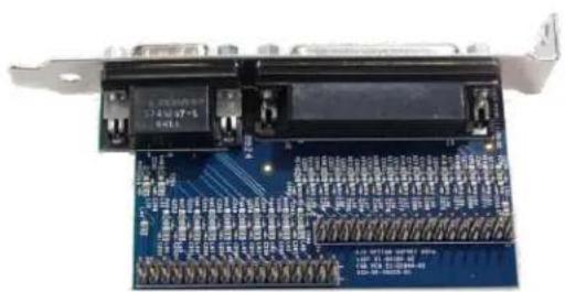
Figure 1. A/V Opon Figure 2. Ribbon Cables
natural_image
Close-up of a blue electronic circuit board with visible traces and connectors (no readable text or symbols)
natural_image
Two identical cable or wire mesh structures with rainbow-colored wires, no text or symbols visibleThe Osprey 460e A/V Opon kit contains the following:
• A/V Option Board
- 2 ribbon cables
A/V Opon Board
The Osprey 460e A/V Opon Board (Figure 3) has two connectors, an industry standard DB25 female connector and a DB15 male connector (see pinout tables). Balanced audio is provided on the DB25 connector and it is TASCAM DTRS compatible.
Figure 3. A/V Opon Board (Front View)

DB25

H = Hot
C = Cold
G = Ground
DB 25 Pinouts
| Pin | Descripon |
| 1 | D Right + |
| 2 | D Right Shield |
| 3 | D Le - |
| 4 | C Right + |
| 5 | C Right Shield |
| 6 | C Le - |
| 7 | B Right + |
| 8 | B Right Shield |
| 9 | B Le - |
| 10 | A Right + |
| 11 | A Right Shield |
| 12 | A Le - |
| 13 | Empty |
| Pin | Descripon |
| 14 | D Right - |
| 15 | D Le + |
| 16 | D Le Shield |
| 17 | C Right - |
| 18 | C Le + |
| 19 | C Le Shield |
| 20 | B Right - |
| 21 | B Le + |
| 22 | B Le Shield |
| 23 | A Right - |
| 24 | A Le + |
| 25 | A Le Shield |
DB15

DB 15 Pinouts
| Pin | Composite | Component | Y/C |
| 1 | A4 | A-Pr | A-S-Chroma |
| 2 | B3 | B-Pb | |
| 3 | C2 | C-Y | C-S-Luma |
| 4 | C4 | C-Pr | C-S-Chroma |
| 5 | D3 | D-Pb | |
| 6 | A3 | A-Pb | |
| 7 | B2 | B-Y | B-S-Luma |
| 8 | B4 | B-Pr | B-S-Chroma |
| 9 | C3 | C-Pb | |
| 10 | D2 | D-Y | D-S-Luma |
| 11 | A2 | A-Y | A-S-Luma |
| 12 | Shield/Gnd | Shield/Gnd | Shield/Gnd |
| 13 | Shield/Gnd | Shield/Gnd | Shield/Gnd |
| 14 | Shield/Gnd | Shield/Gnd | Shield/Gnd |
| 15 | D4 | D-Pr | D-S-Chroma |
Connecting the A/V Option to the Osprey card
Note: It is best to use a grounding strap when performing these steps.
To connect the A/V opon:
- Locate Audio pin 1 on the Osprey 460e card (Figure 4).
Figure 4. Osprey 450e Video Capture Card

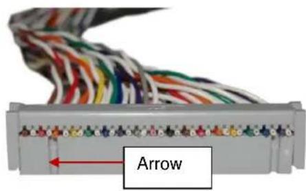
- An arrow is located at one end of the ribbon cable (Figure 5). Align the arrow to Audio pin 1.
Figure 5. Ribbon Cable End
-
Connect the ribbon cable by pressing down rmly.
-
Locate Audio pin 1 on the A/V opon board (Figure 6).
Figure 6. A/V Opon Board

- Locate the arrow at the other end of the ribbon cable. Align this arrow to Audio pin 1 on the A/V opon board.
- Connect the ribbon cable by pressing down rmly.
- Repeat steps 1 through 6 for video.
Make sure the ribbons do not cross.
Figure 7. Complete Assembly

natural_image
Close-up of a computer motherboard with colorful cable routing (no visible text or symbols)Note: The recommended procedure is to install the driver software prior to installing the Osprey video capture card in the computer. As soon as you install an Osprey card in the PC, the card and its drivers are detected automatically.
- Install the driver and follow the prompted instrucons.
- Turn o the computer and install the Osprey 460e or 450e and the A/V Opon Card.
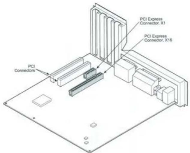
WARNING!: Be sure to install the card in the PCI Express slot. This slot is usually black. Refer to Figure 8 as a guide. Placing the card in the wrong slot can damage the card.
Figure 8. PCI Express Slot
-
Power up the computer. The OS will detect the newly present Osprey card, and begin to acvate the driver.
-
When the installaon is complete, reboot the system.
Configuring the additional A/V inputs
The Osprey 460e and 450e have four independent channels which are denoted by A, B, C, and D. Each channel can support up to four composite inputs, a component input, and a Y/C input. With the addition of the A/V opon and component panel, the Osprey AVStream Driver enables you to select any of these as physical inputs to each channel.
As an example, the driver lists Osprey 460 Device 1A, 1B, 1C and 1D. The number "1" indicates the first physical Osprey 460e card in a system. A second card is listed as Osprey 460 Device 2A, 2B, and so on.
Figure 9. Property Page

To congregate the A/V inputs:
- Select Video Filter on Device 1A (Figure 9). The Property page displays (Figure 10).
Figure 10. Video Input Drop-Down List

- Click on the Video Input drop-down list to display all of the available video inputs for channel A, Composite1, Composite2, Composite3, Composite4, Y/C (S-Video) and Component.
Note: The Osprey 460e can capture video from only one of the four composite video inputs at any given time.
See the Osprey driver manual for information on changing the inputs.
- Click OK.
Connecting to the optional panels
The oponal panels include the cables that connect to the A/V opon connectors or the Osprey 460e or 450e video capture card and a standard 19-inch rack panel. Cables are removable from the panels.
Figure 11. 95-00463 Osprey 460e Component Video Panel

On the Component panel, Composite 2, Composite3 and Composite4 are indicated by A2, A3, and A4 for the A channel. Composite1 (A1) would be the physical input on the bracket of the Osprey 460e video capture card. Y/C (S-Video) is indicated by S-Luma and S-Chroma. Component is indicated by Y, Pb and Pr.
Figure 12. 95-00462 Osprey 460e Balanced Audio Panel

The balanced audio panel brings out 4 stereo pairs of balanced audio from the A/V opon DB25 connector.
Figure 13. 95-00460 Osprey 460e/440 Breakout Panel

natural_image
Front panel of a network equipment unit with multiple ports and connectors (no visible text or symbols)The Osprey 460e/440 breakout panel extends the connector on the Osprey 460e, 450e, or 440 video capture card to the panel. This includes the 4 composite video connectors (BNC) and the 4 pairs of unbalanced stereo audio (RCA) from the breakout cable.
Osprey®
by VARIOSYSTEMS
ospreyvideo.com


Brand : Osprey
Model : 460e
Category : Video Capture Card