
ALF-IPCONTROLLER - Régulateur Alfatron - Free user manual and instructions
Find the device manual for free ALF-IPCONTROLLER Alfatron in PDF.


| Product Type | IP PTZ Camera Controller |
| Brand | Alfatron |
| Model | ALF-IPCONTROLLER |
| Dimensions | 320 x 180 x 100 mm |
| Power Supply | DC 12V 1A (±10%) |
| Power Consumption | 0.6 W Max |
| Operating Temperature | 0°C to 50°C |
| Storage Temperature | -20°C to 70°C |
| Ethernet Port | 1 x RJ45 |
| Joystick | 4-axis (up/down/left/right) with zoom control |
| Display | LCD |
| Control Modes | IP VISCA, ONVIF, VISCA, PELCO |
| Control Protocols | VISCA, ONVIF, PELCO |
| Button Sound Prompts | On/Off toggle |
| Auto Focus | Yes (AUTO FOCUS button) |
| Auto Aperture | Yes (AE AUTO button) |
| White Balance | Auto/Manual (WBC MODE button) |
| Preset Setting | Up to 4 camera presets (PRESET and CALL buttons) |
| Zoom Control | T-ZOOM-W rocker |
| Back Panel Interfaces | RS422, RS232, Ethernet, DC12V, Power Switch |
| Warranty | 7 years limited |
Frequently Asked Questions - ALF-IPCONTROLLER Alfatron
User questions about ALF-IPCONTROLLER Alfatron
0 question about this device. Answer the ones you know or ask your own.
Ask a new question about this device
Download the instructions for your Régulateur in PDF format for free! Find your manual ALF-IPCONTROLLER - Alfatron and take your electronic device back in hand. On this page are published all the documents necessary for the use of your device. ALF-IPCONTROLLER by Alfatron.
USER MANUAL ALF-IPCONTROLLER Alfatron
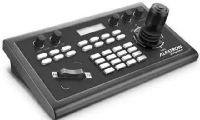
IP PTZ Camera Controller
natural_image
Black ALFATRON audio recording device with control buttons and playback controls (no visible text or symbols on main body)Content
PREFACE 2
PRECAUTIONS....3
1. Product Overview ....4
1.1 Product Features ....4
1.2 Wiring Diagram ....4
1.3 Technical Specifications....5
2. Function Description....5
2.1 Button Description ....5
2.2 Rocker Switch and Knob....6
2.3 Joystick Control....8
2.4 Terminal Description of Back Panel Interfaces 8
3. Local Settings (SETUP)....9
3.1 Basic Settings....9
3.2 VISCA & IP VISCA Mode shared Setting....9
3.3 IP VISCA Mode Setting 9
3.4 VISCA Mode Setting 10
3.5 PELCO Mode Setting....10
3.6 ONVIF Mode Setting....10
4. Connection and Control ....10
4.1 Connection and Control in ONVIF Mode 10
4.2 Connection and Control in IP VISCA Mode 11
4.3 Control in VISCA & PELCO Mode 11
5. Web Page Configuration....12
5.1 Home Page 12
5.2 LAN Settings 13
5.3 Upgrade....13
5.4 Restore Factory....13
5.5 Reboot....13
6. Warranty....14
Preface
Read this user manual carefully before using this product. Pictures shown in this manual are for reference only, different model and specifications are subject to
real product.
This manual is only for operation instruction only, not for any maintenance usage. Any changes of functions and parameters since then will be informed separately. Please refer to the dealers for the latest details.

FCC Statement
This equipment generates, uses and can radiate radio frequency energy and, if not installed and used in accordance with the instructions, may cause harmful interference to radio communications. It has been tested and found to comply with the limits for a Class A digital device, pursuant to part 15 of the FCC Rules. These limits are designed to provide reasonable protection against harmful interference in a commercial installation.
Operation of this equipment in a residential area is likely to cause interference, in which case the user at their own expense will be required to take whatever measures may be necessary to correct the interference
Any changes or modifications not expressly approved by the manufacture would void the user's authority to operate the equipment.

Do not dispose of this product with the normal household waste at the end of its life cycle. Return it to a collection point for the recycling of electrical and electronic devices. This is indicated by the symbol on the product, user manual or packaging. The materials are reusable according to their markings. By reusing, recycling or other forms of utilisation of old devices you make an important contribution to the protection of our environment. Please contact your local authorities for details about collection points.
Precaution
- What is the function of CAM NUM when add a network device?
CAM NUM will be associated and bound with the currently entered IP and port information.
It will quickly switch to the CAM NUM bound device when adding a device with CAM button.
- How to enter English when set the username, password and custom keys of F1/F2.
For example: to enter letter C, simply press the number key "2" three times continuously in the input interface.
- How to enter IP address?
The camera controller doesn't have "." button; So please enter the IP address with four segments.
Take IP address 192.168.0.1 for example, it will automatically jump to next segment when finished input 192 and 168; while after input 0, you have to move the joystick rightward to switch to next segment input.
- How to clear in input mode?
Move the joystick leftward to clear the input information.
- The home page of each mode refers to the displayed page when controller initialization complete.
In IP VISCA and ONVIF Mode, if you see the prompts of "Visca!" and "Onvif!", the IP address displayed on the screen is local IP address of the controller. While the prompts of "Visca:" and "Onvif:" shown on the page, the IP address displayed on the screen belongs to the connected device.
1. Product Overview
1.1 Product Features
Four control modes: Two IP control modes (IP VISCA & ONVIF); Two analog control modes (RS422 & RS232)
Three Control Protocols: VISCA, ONVIF and PELCO
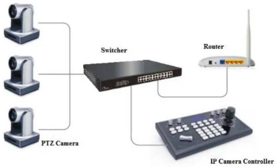
1.2 Wiring Diagram
The controller and PTZ camera must be connected to the same LAN, and IP addresses must at the same segment.
For example:
192.168.1.123 is at the same segment with 192.168.1.111
192.168.1.123 is not at the same segment with 192.168.0.125
The default setting for IP controller is obtaining IP address dynamically.
flowchart
graph TD
    A["PTZ Camera"] --> B["Switcher"]
    C["Router"] --> B
    D["IP Camera Controller"] --> B
    B --> E["Output"]
1.3 Technical Specifications
| Ethernet | One Ethernet port |
| Joystick | Four-dimensional (up, down, left, right) joystick control andclock, Zoom Tele/Wide |
| Connection Lead | |
| Display LCD | |
| Prompt Tone | Button Sound Prompts Open/Off |
| Power supply | DC 12V1A±10% |
| Power Consumption | 0.6 W Max |
| Operating Temperature | 0°C-50°C |
| Storage Temperature | -20-70°C |
| Dimensions(mm) 320*180*100 | |
2. Function Description
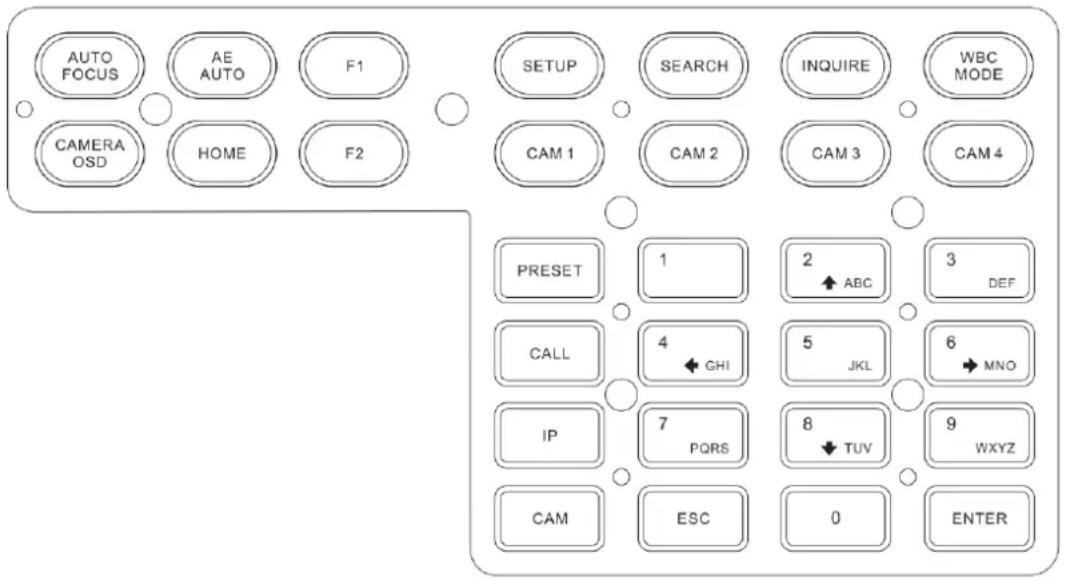
2.1 Button Description
【AUTO FOCUS】
Auto Focus button: Set the camera in auto focus mode with this button. It will light up when camera is in manual focus mode.
【AE AUTO】
Auto Aperture button: Set the camera in automatic aperture mode with this button. It will light up when camera is in manual aperture mode.
【CAMERA OSD】
Camera OSD button: call/Close the camera OSD
【HOME】
HOME button: The camera will back to home position if camera OSD is off. While when the camera OSD is called out, the home button is confirming function of camera OSD.
【F1】\~【F2】
Custom function buttons: Custom functions in VISCA and IP VISCA modes.
【SETUP】
Controller local Settings button: Modify and view local settings.
【SEARCH】
Search button: Search for all available devices with ONVIF protocol in the LAN (only in ONVIF Mode)
【INQUIRE】
Inquire button: Check added devices
【WBC MODE】
Auto white balance button: Set the camera in auto white balance mode. It will light up when camera is in manual white balance mode.
【CAM1】\~【CAM4】
Quickly switch device button: Quickly switch to CAM NUM 1-4 devices (ONVIF, IP VISCA), or to address code 1-4 devices (VISCA, PELCO)
【PRESET】
Short press to set presets; long press to delete presets setting.
It needs to work with the number keys and "enter" button, for setting or deleting presets.
【CALL】
Call preset button: It needs to work with the number keys and ENTER button.
【IP】
Manually add network device button:
Manually add network devices (only in ONVIF and IP VISCA modes)
【CAM】
In IP VISCA and ONVIF modes, it will quickly switch to the CAM NUM bound device when adding a device via CAM.
In VISCA and PELCO modes, it will switch to the address code when entering a certain address.
It needs to work with the number keys and "enter" button.
【1】\~【9】
Number keys of 0,1,2,3,4,5,6,7,8,9.
2,4,6,8 serve as direction keys as well, which could control pan and tilt rotation, and camera OSD.
【ESC】Return
【ENTER】Confirm Button
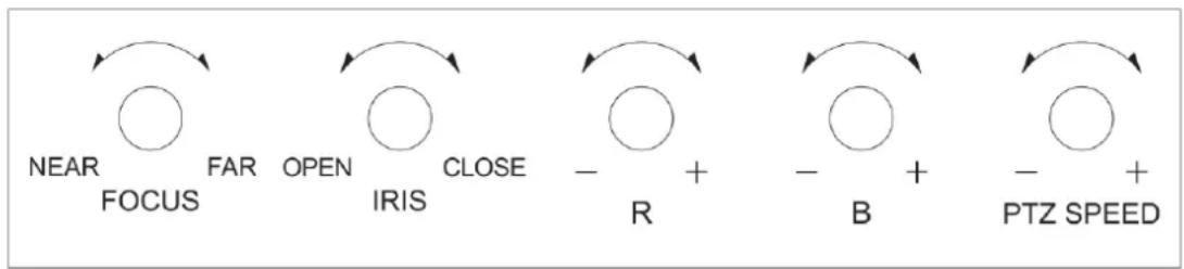
2.2 Rocker Switch and Knob
flowchart
graph LR
    A["NEAR"] --> B["FORCUUS"]
    C["FAR"] --> D["OPEN"]
    E["OPEN"] --> F["CLOSE"]
    G["OPEN"] --> H["IRIS"]
    I["OPEN"] --> J["R"]
    K["OPEN"] --> L["B"]
    M["OPEN"] --> N["PTZ SPEED"]
【NEAR】【FAR】Manually adjust the focal length.
【OPEN】【CLOSE】Manually adjust the aperture, OPEN(Aperture Plus)/CLOSE(Aperture minus)
【R-】【R+】Manually adjust the Red Gain
【B-】【B+】Manually adjust the Blue Gain
【PTZ SPEED-】【PTZ SPEED+】Adjust PTZ Speed, Gears 1 (Slow)-8(Fast)
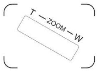
【T-ZOOM-W】Zoom Tele and Zoom Wide.
2.3 Joystick Control
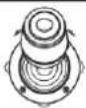 | Up | 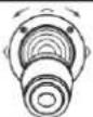 | Down |  | Left |
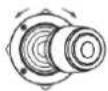 | Right | 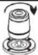 | Zoom In | 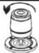 | Zoom Out |
2.4 Terminal Description of Back Panel Interfaces
Back Panel Details: RS422, RS232, DC-12V, Ethernet, Power Switch

| Number | Label | Physical interface | Description |
| 1 | RS422 | Control Output (TA, TB, RA, RB) | 1. Connect to RS422 bus of the camera: TA to camera RA; TB to camera RB; RA to camera TA; RB to camera TB. |
| 2 Ground Control line | ground (G ) | Control signal Line ground | |
| 3 | ETHERNET | Ethernet port | Network connection |
| 4 | DC-12V | Power input | DC 12V Power input |
| 5 | POWER | Power switch | Power on/ off |
3. Local Settings (SETUP)
3.1 Basic Settings
Move the joystick up and down to switch 1 to 2, and 2 to 3 settings; Move the joystick left and right to switch on and off the button sound prompts, confirm with ENTER button.
(1) Delete device
(2) Network Type: dynamic and static
(3) Button sound prompt: on and off
(4) Language setting: Chinese and English
(5) Mode: VISCA, IP VISCA, ONVIF, PELCO
(6) Local IP
(7) Version information
(8) Restore factory settings
3.2 VISCA & IP VISCA Mode shared Setting
(1) F1: Custom function for F1 button (VISCA command)
(2) F2: Custom function for F2 button (VISCA command)
Input custom name → ENTER → Input VISCA command
For example: the command is 8101040702FF, then input 01040702 (0 can't be omitted)
3.3 IP VISCA Mode Setting
Delete the saved device:
Move the joystick up and down to view devices; Move the joystick rightward to view the device's port information; Move the joystick leftward to view the IP, CAM NUM information; ENTER to delete the selected device.
3.4 VISCA Mode Setting
Control settings (set the baud rate for a certain address code):
Move the joystick up, down, left and right to switch addresses (1-7) → ENTER → Move the joystick left and right to switch baud rate → ENTER
EX: Select the address: 1 → ENTER → Select the baud rate: 9600 → ENTER
When the controller switch to address 1, the control baud rate is 9600
3.5 PELCO Mode Setting
Control settings (set the baud rate for a certain address code):
Move the joystick up, down, left and right to switch addresses (1-255) → ENTER → Move the joystick left and right to choose protocols → ENTER → Move the joystick left and right to switch baud rate → ENTER
EX: Select the address: 1 → ENTER → Select the protocol: PELCO-D → ENTER → Select the baud rate: 9600 → ENTER
When the controller switch to address 1, the control baud rate is 9600, protocol is PELCO-D
3.6 ONVIF Mode Setting
Delete saved device:
Move the joystick up and down to view devices; Move the joystick rightward to view the device's port information; Move the joystick leftward to view the IP, CAM NUM information; ENTER to delete the selected device.
4. Connection and Control
4.1 Connection and Control in ONVIF Mode
Search and Add
In ONVIF mode, follow the steps below to add a LAN device to the PTZ controller:
(1) After the controller obtained IP address, simply press the SEARCH button.
(2) All available devices with ONVIF protocol in the LAN will be displayed on the controller when search process is complete.
(3) Move the joystick up/down to select the device, press the ENTER button to confirm.
(4) It's required to enter the device's username, password and CAM NUM information when adding a device.
(5) Press the ENTER button to save.
(6) Alternatively, to add a device via【IP】 button manually.
(7) Press the INQUIRE button to view the added device; Move the joystick up/down to view the saved device (move the joystick rightward to view the port); Press the ENTER button to select a camera to control, or use the CAM button to connect and control.
4.2 Connection and Control in IP VISCA Mode
Searching function is not available in IP VISCA mode, but to manually add a device.
(1). Manually add device via the 【IP】 button.
(2) Press the INQUIRE button to view the added device; Move the joystick up/down to view
the saved device (move the joystick rightward to view the port); Press the ENTER button to select a camera to control or use the CAM button to connect and control.
4.3 Control in VISCA & PELCO Mode
Simply set the address code and baud rate to control.
In PELCO Mode, correctly set the PELCO-D or PELCO-P protocol is required.
5. Web Page Configuration
5.1 Home Page
(1) Connect the controller and computer to the same LAN and enter the controller's IP address into the browser.
(2) Default username: admin ; Password: empty
(3) Home page is as below:
![NET KEYBOARD [1] 192.168.5.163:2000 Add All Add Delete Del All Device IP 107.158.5.163 Onvif Port 2000 Cam Num 1 Username admin Password admin Search Update Handle Save](/content/2026/05/834163/images/6ab623f52eae05c981ee87ca9b2ab46b5c748b4601ac107314d78ca068e4c58d.jpg)
(4) Home page consists of three segments: Search Device List (green); Added Device List (blue) or Manually Add (yellow); Device Details (orange).
(5) Click "Search" button to find ONVIF devices in the LAN, which will be displayed in the green frame automatically.
(6) Select the device in the "Search Device List" and click "Add" to complete. Press "Ctrl" for multiple selections.
(7) Select the device in the "Added Device List" and click "Delete" to complete. Press "Ctrl" for multiple selections.
(8) After successfully add a device, click the IP address in the "Added Device List" to edit the account and port information of the device.
(9) After addition, deletion, and modification, click "Save" button to take effect.
PS. Any modification to the configuration on home page needs to be saved by click "Save" button; otherwise the modification is invalid.
5.2 LAN Settings
To modify the device IP access way and port parameters in LAN Settings, as shown below:
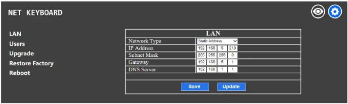
Dynamic address (default access way): The Controller will automatically acquire IP address from the router.
Static address: Change the network to static address when necessary; simply input the network segment information to modify.
5.3 Upgrade
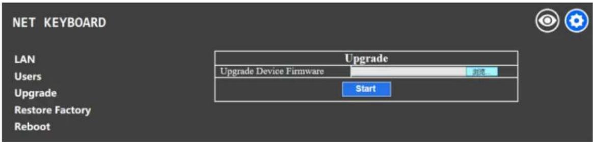
The upgrade function is applied for maintenance and update.
Choose the right upgrading file and click "start" to update the controller. It will auto reboot after updating.
PS: Do not operate the controller during the upgrade process. Do not power off or disconnect network
5.4 Restore Factory
Restore the controller to factory default settings when unexpected failure occurs due to incorrect modifications. Please use it with caution if the controller works well.
5.5 Reboot
Click Reboot for maintenance if the controller runs for a long time.
6.Warranty
1.1 This limited warranty covers defects in materials and workmanship in this product.
1.2 Should warranty service be required, proof of purchase must be presented to the Company. The serial number on the product must be clearly visible and not have been tampered with in any way whatsoever.
1.3 This limited warranty does not cover any damage, deterioration or malfunction resulting from any alteration, modification, improper or unreasonable use or maintenance, misuse, abuse, accident, neglect, exposure to excess moisture, fire, improper packing and shipping (such claims must be presented to the carrier), lightning, power surges, or other acts of nature. This limited warranty does not cover any damage, deterioration or malfunction resulting from the installation or removal of this product from any installation, any unauthorized tampering with this product, any repairs attempted by anyone unauthorized by the Company to make such repairs, or any other cause which does not relate directly to a defect in materials and/or workmanship of this product. This limited warranty does not cover equipment enclosures, cables or accessories used in conjunction with this product.
This limited warranty does not cover the cost of normal maintenance. Failure of the product due to insufficient or improper maintenance is not covered.
1.4 The Company does not warrant that the product covered hereby, including, without limitation, the technology and/or integrated circuit(s) included in the product, will not become obsolete or that such items are or will remain compatible with any other product or technology with which the product may be used.
1.5 Only the original purchaser of this product is covered under this limited warranty. This limited warranty is not transferable to subsequent purchasers or owners of this product.
1.6 Unless otherwise specified, the goods are warranted in accordance with the manufacturer's product specific warranties against any defect attributable to faulty workmanship or materials, fair wear and tear being excluded.
1.7 This limited warranty only covers the cost of faulty goods and does not include the cost of labor and travel to return the goods to the Company's premises.
1.8 In the event of any improper maintenance, repair or service being carried out by any third persons during the warranty period without the Company's written authorization, the limited warranty shall be void.
1.9 A 7 (seven) year limited warranty is given on the aforesaid product where used correctly according to the Company's instructions, and only with the use of the Company's components.
1.10 The Company will, at its sole option, provide one of the following three remedies to whatever extent it shall deem necessary to satisfy a proper claim under this limited warranty:
1.10.1 Elect to repair or facilitate the repair of any defective parts within a reasonable period of time, free of any charge for the necessary parts and labor to complete the repair and restore this product to its proper operating condition.; or
1.10.2 Replace this product with a direct replacement or with a similar product deemed by the Company to perform substantially the same function as the original product; or
1.10.3 Issue a refund of the original purchase price less depreciation to be determined based on the age of the product at the time remedy is sought under this limited warranty.
1.11 The Company is not obligated to provide the Customer with a substitute unit during the limited warranty period or at any time thereafter.
1.12 If this product is returned to the Company this product must be insured during shipment, with the insurance and shipping charges prepaid by the Customer. If this
product is returned uninsured, the Customer assumes all risks of loss or damage during shipment. The Company will not be responsible for any costs related to the removal or
re-installation of this product from or into any installation. The Company will not be responsible for any costs related to any setting up this product, any adjustment of user controls or any programming required for a specific installation of this product.
1.13 Please be aware that the Company's products and components have not been tested with competitor's products and therefore the Company cannot warrant products and/or components used in conjunction with competitor's products.
1.14 The appropriateness of the goods for the purpose intended is only warranted to the extent that the goods are used in accordance with the Company's installation, classification, and usage instructions.
1.15 Any claim by the Customer which is based on any defect in the quality or condition of the goods or their failure to correspond with specification shall be notified in writing to the Company within 7 days of delivery or (where the defect or failure was not apparent on reasonable inspection by the Customer) within a reasonable time after discovery of the defect or failure, but, in any event, within 6 months of delivery.
1.16 If delivery is not refused, and the Customer does not notify the Company accordingly, the Customer may not reject the goods and the Company shall have no liability and the Customer shall pay the price as if the goods had been delivered in accordance with the Agreement.
1.17 THE MAXIMUM LIABILITY OF THE COMPANY UNDER THIS LIMITED WARRANTY SHALL NOT EXCEED THE ACTUAL PURCHASE PRICE PAID FOR THE PRODUCT

- IP PTZ Camera Controller
- Content
- PREFACE 2
- PRECAUTIONS....3
- Product Overview ....4
- Function Description....5
- Local Settings (SETUP)....9
- Connection and Control ....10
- Web Page Configuration....12
- Warranty....14
- Preface
- FCC Statement
- Precaution
- Product Overview
- Product Features
- Wiring Diagram
- Technical Specifications
- Function Description
- Button Description
- 【AUTO FOCUS】
- 【AE AUTO】
- 【CAMERA OSD】
- 【HOME】
- 【F1】\~【F2】
- 【SETUP】
- 【SEARCH】
- 【INQUIRE】
- 【WBC MODE】
- 【CAM1】\~【CAM4】
- 【PRESET】
- 【CALL】
- 【IP】
- 【CAM】
- Rocker Switch and Knob
- Joystick Control
- Terminal Description of Back Panel Interfaces
- Local Settings (SETUP)
- Basic Settings
- VISCA & IP VISCA Mode shared Setting
- IP VISCA Mode Setting
- VISCA Mode Setting
- PELCO Mode Setting
- ONVIF Mode Setting
- Connection and Control
- Connection and Control in ONVIF Mode
- Search and Add
- Connection and Control in IP VISCA Mode
- Control in VISCA & PELCO Mode
- Web Page Configuration
- Home Page
- LAN Settings
- Upgrade
- Restore Factory
- Reboot
- 6.Warranty
Brand : Alfatron
Model : ALF-IPCONTROLLER
Category : Régulateur