
65WR6BE - Tableau blanc et accessoires HISENSE - Free user manual and instructions
Find the device manual for free 65WR6BE HISENSE in PDF.


| Product Type | Interactive Digital Board (Whiteboard) |
| Model | 65WR6BE |
| Dimensions (W x H x D) | 1497 x 915 x 100 mm |
| Weight (without base) | 36.9 kg |
| Power Supply | 100-240V ~ 50/60Hz, 2.7A |
| Display Resolution | 3840 x 2160 (4K UHD) |
| Audio Output | 15W + 15W built-in speakers |
| VESA Mounting | 600 x 400 mm, M8 x 25 screws |
| Input Ports | HDMI (x2), DP, USB 3.0 (x2), USB 2.0, RS232, LAN, OPS |
| Output Ports | HDMI OUT, Digital Audio OUT (coaxial), Headphone |
| Touch Technology | Infrared touch with stylus and gesture support |
| Included Accessories | 2 styluses, remote control, batteries, power cord, wall mount bracket, wireless cast dongle |
| Wireless Connectivity | Wi-Fi (2.4/5 GHz), Bluetooth, NFC |
| Operating System | Android-based (custom Hisense interface) |
| Whiteboard Software | Pre-installed Vision Board with handwriting, shapes, file insertion |
| Camera (Optional) | External camera compatible via dedicated port |
| OPS Module Support | Yes, OPS-C Plus slot for embedded PC |
| Environmental Temperature | Operating: 5°C to 35°C |
| Cleaning | Unplug device, use lightly dampened cloth (no liquid cleaners) |
| Safety Features | Overload protection, ventilation requirement (10cm gap), power surge protection |
Frequently Asked Questions - 65WR6BE HISENSE
User questions about 65WR6BE HISENSE
0 question about this device. Answer the ones you know or ask your own.
Ask a new question about this device
Download the instructions for your Tableau blanc et accessoires in PDF format for free! Find your manual 65WR6BE - HISENSE and take your electronic device back in hand. On this page are published all the documents necessary for the use of your device. 65WR6BE by HISENSE.
USER MANUAL 65WR6BE HISENSE
Read the manual carefully and ensure you have fully understood its contents before operating this device for the first time.
Contents
- Safety Precautions.... 1
- Introduction .... 5
2.1 Package Contents......5
2.2 Products View 6
2.3 Remote Control 9
- Installation Guide....11
3.1 Precautions for Installation....11
3.2 Wall Mount Kit Specifications (VESA) 12
3.3 Installing the OPS (Optional).... 13
3.4 Installing the Camera (optional).... 15
-
Making Connections ...... 18
-
Getting Started 23
- Using the Vision Board.... 24
6.1 Initial Launch Setup 24
6.2 Homepage and Taskbar.... 25
6.3 Using Gestures.... 27
6.4 Settings.... 28
6.5 White Board 31
6.6 Source 42
6.7 File Manager 42
6.8 App 49
6.9 Wireless Cast 51
6.10 Split Screen Collaboration.... 54
6.11 Apps Installation 55
6.12 Software Updates 56
6.13 IP Control 57
-
Serial Protocol.... 59
-
Appendix 62
8.1 Specification....62
8.2 Other Infomation.... 65
8.3 Certification and Compliance.... 66
8.4 EU Declaration of Conformity (DOC).... 67
- Troubleshooting 73
1. Safety Precautions
Declaration
Any content and service accessed through this device shall be the property of the applicable third party and subject to protection by regulations and laws on copyright, patent, trademark and other intellectual property rights. No part of such content and service may be modified, duplicated, published, uploaded, distributed, translated, marketed, or used to make and distribute products derived from it without the prior permission of the content owner or service provider.
The manufacturer hereby declares explicitly that the manufacturer shall not be held liable for any guarantee and conditions implied related to this device and any content and service, including but not limited to warranty on marketability, satisfactory quality, fitness for a particular purpose, accuracy, quiet use and non-violation of any third party's rights. To the maximum extent permitted by applicable law, the manufacturer gives no guarantee on the accuracy, validity, timeliness, legitimacy and completeness of any content or service provided through this device, or the fitness of such device, content or service for your particular requirement, or the protection from interruption and error during operation of such device, content or service. To the maximum extent permitted by applicable law, in any case, including fault or neglect, the manufacturer shall not be held liable for legal actions or indemnity obligation arising from any consequence as a result of or related to any information loaded in this device or use of such device, content or service by you or any third party.
Any content or service provided as it is together with this device shall be the property of the applicable third party, therefore Manufacturer gives no declaration or warranty on modification, suspension, cancellation, termination or abortion thereof, and shall not be held liable for legal actions or indemnity obligation arising thereof.
Manufacturer reserves the rights to restrict the use or access of certain content or service. As the contents and services are transmitted through third party's network and transmission facilities, Manufacturer undertakes no customer service thereof or the obligation for such customer service.
Statement
- The pictures and instructions in this user manual are for reference only, and may be different from the actual product. Please subject to the actual product. (This statement is valid throughout the entire user manual.)
• Quality upgrades, product design and specifications are subject to change without notice. - The software content service applicable to this product depends on the third party provider, and some software may not be used due to network, region, service cycle and other problems, which has nothing to do with the product quality. Please contact the third party provider for relevant details.

This symbol alerts user about the presence of a dangerous voltage not isolated inside the product which can be sufficiently powerful to constitute a risk of electrocution.

This symbol alerts user about the presence of important operating instructions and maintenance in the document enclosed in the package.

ATTENTION
RISK OF SHOCK ELECTRIC

Do not open the back cover.
In no case the user is allowed to operate inside the device. Only a qualified technician is entitled to operate.

AC voltage: This symbol indicates that the rated voltage marked with the symbol is AC voltage.

DC voltage: This symbol indicates that the rated voltage marked with the symbol is DC voltage.

Class I product: This symbol indicates that it requires a safety connection of protective earthing (ground).
Disposal of Used Electrical & Electronic Equipment

Packaging and electrical goods should be recycled appropriately, and not treated as household waste. Please dispose of this equipment at your applicable collection point for the recycling of electrical & electronic equipment waste. By ensuring the correct disposal of this product, you will help prevent potentially hazardous to the environment and to human health, which could otherwise be caused by unsuitable waste handling of this product. The recycling of materials will help conserve natural resources. Please do not therefore dispose of your old electrical and electronic equipment with your household waste. For more detailed information about recycling of this product, please contact your local city office, your household waste disposal service or the shop where you purchased the product.
Important Notice
Paragraphs beginning with the symbol ▲ indicate important instructions, tips or conditions for the following settings.

your own safety and the optimal performance of your screen, ensure to read the safety instructions before performing any installation.
Compatibility with 3rd party products, software and services are not guaranteed. We cannot be held liable for any damage or loss suffered whilst operating, using or connecting to incompatible devices or apps.
The recording and playback of content on this or any other device may require permission from the owner of the copyright or other such rights in that content. It is your responsibility to ensure that your use of this or any other device complies with applicable copyright legislation in your country. Please refer to that legislation for more information on the relevant laws and regulations involved or contact the owner of the rights of the content you wish to record or playback.
Read these instructions
Follow all instructions
Heed all warnings
Keep these instructions
All rights reserved.



Safeguards
Please read the following safeguards for your device and retain for future reference.
Always follow all warnings and instructions marked on the device.
-
A note about safety and operating instructions
Read and follow all safety and operating instructions, and retain them safely for future reference. -
Heed Warnings
Adhere to all warnings on the appliance and in the operating instructions.
- Cleaning
Unplug the device from the wall outlet before cleaning. Do not use liquid, abrasive, or aerosol cleaners. Cleaners can permanently damage the cabinet and screen. Use a lightly dampened cloth for cleaning.
- Water and Moisture
Avoid dripping or splashing of liquids onto the product. Objects filled with liquids, such as vases, should not be placed on the product.
- Ventilation
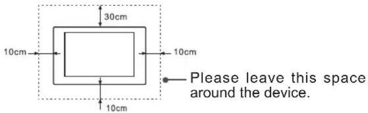
Slots and openings in the cabinet are provided for ventilation, to ensure reliable operation of the device and to protect it from overheating. Do not cover the ventilation openings in the cabinet and never place the set in a confined space such as built-in cabinet unless proper ventilation is provided. Leave a minimum 10cm gap all around the unit.
- Power Source
This device should be operated only from the type of power source indicated on the marking label. If you are not sure of the type of power supplied to your home, consult your appliance dealer or local power company.
- Power-Cord Protection
Power- supply cords should be routed so that they are not likely to be walked on or pinched by items placed upon or against them, paying particular attention to cords at plug, wall outlets, and the point where they exit from the device. Main plug is used as the disconnect device, the disconnect device shall remain readily operable.
- Lightning
For added protection for this device during a lightning storm, or when it is left unattended and unused for long periods of time, unplug it from the wall outlet and disconnect the cable system. This will prevent damage to the device due to lightning or power-line surge.
- Overloading
Do not overload wall outlets and extension cords as this can result in a risk of fire or electric shock.
- Object and Liquid Entry
Never push objects of any kind into this device through openings as they may touch dangerous voltage points or short-out parts that could result in fire or electric shock. Never spill liquid of any kind on or into the device.
Safety Precautions
11. Servicing
Do not attempt to service this device yourself as opening or removing covers may expose you to dangerous voltage or other hazards. Refer all servicing to qualified service personnel.
12. Damage Requiring Service
Unplug the device from the wall outlet and refer servicing to qualified service personnel under the following conditions:
(a) When the power - supply cord or plug is damaged.
(b) If liquid has been spilled, or objects have fallen into the device.
(c) If the device has been exposed to rain or water.
(d) If the device does not operate normally by following the operating instructions. Adjust only those controls that are covered by the operating instructions as an improper adjustment of other controls may result in damage and will often require extensive work by a qualified technician to restore the device to its normal operation.
(e) If the device has been dropped or the cabinet has been damaged.
(f) When the device exhibits a distinct change in performance - this indicates a need for service.
13. Replacement Parts
When replacement parts are required, be sure the service technician has used replacement parts specified by the manufacturer or have the same characteristics as the original part. Unauthorized substitutions may result in fire, electric shock or other hazards.
14. Safety Check
Upon completion of any service or repair to the device, ask the service technician to perform safety checks to determine that the device is in safe operating condition.
15. Heat
The product should be situated away from heat sources such as radiators, heat registers, stoves, or other products (including amplifiers) that produce heat.
16. Fire
The product should be situated away from naked flame sources such as lighted candle.
17. Off-gassing
The device smells of plastic is normal and will dissipate over time.

Incorrect replacement of the battery may lead to the risk, including the replacement of another similar or the same type. Do not expose batteries to heat such as sun or fire or something like that.

The device should not be exposed to dripping and spraying and it cannot be placed under objects filled with liquids.

Main plug is used as the disconnect device, the disconnect device shall remain ready for operating.

Apparatus with CLASS I construction shall be connected to a MAINS socket outlet with a protective earthing connection.
2. Introduction
2.1 Package Contents
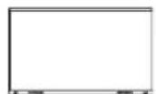
WR6BE × 1
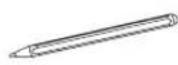
Stylus × 2
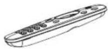
Remote Control
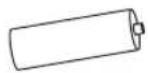
Battery × 2
User Manual of the Device Wall Mount Bracket
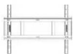
Wall Mount Bracket
Accessories bag
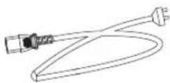
Power Cord (It depends on the models, regions, or countries.)
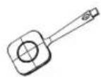
Wireless Cast
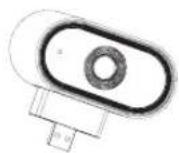
Camera × 1 (Optional)
User Manual of Wireless Cast × 1 (Optional)
NOTE
- The accessories may be different from the list above due to different models, countries/regions, please refer to the actual accessory bag.
2.2 Products View
2.2.1 Front Panel | Control Panel
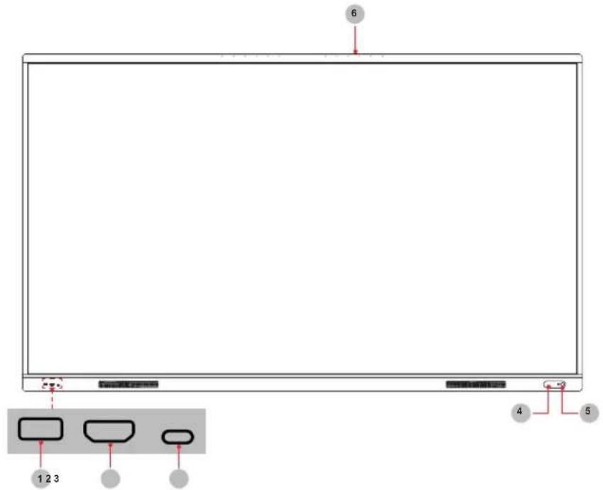
| Number Item Description | ||
| 1 USB | 3.0 | It is a USB interface, which can be used as the media playback interface of the device and the USB interface of embedded OPS module. It is also the USB used to synchronize the USB-A dongle |
| 2 HDMI | The front HDMI interface allows digital audio and video signals to be transmitted using a single cable without compression. HDMI supports multi-channel digital audio, and can be connected to external devices with HDMI port, such as computer host, set-top box, Blu-ray player, A/V device, etc. | |
| 3 Type-C | It is a full-featured Type-C interface, which supports audio, video, and file transmission. | |
| 4 NFC | When the mobile phone touches the device, it can achieve screen sharing through mobile phone NFC function. | |
| 5 | Standby button | When the device is on, short press the button to turn off the screen, long press the button to go into standby mode.When the screen is off, press the button to open the screen, and when the device is on standby, press the button to start.The indicator light displays the state of power on or standby:When the device is on, the light is blue.When standby, the light is red.When the device with OPS module is turned on, the light is green. |
| 6 | MIC hole | Microphone |
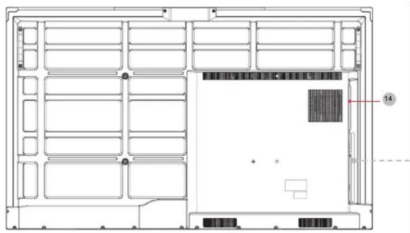
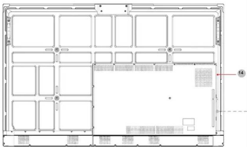
2.2.2 Rear Panel | I/O Panel
65" 75"
86"
natural_image
Technical line drawing of a server rack or chassis with labeled components (no text or symbols beyond basic labels)
natural_image
Technical line drawing of a server rack or chassis frame with grid layout and mounting points (no text or symbols)Introduction
| Number | Port Description | |
| 1 AC | Switch Turn on/off AC power supply“I”=Power on, “O”=Power off | |
| 2 AC | INPUT AC power input | |
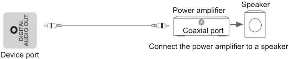
| 3 DIG | TAL AUDIO OUT | Connect to power amplifier via coaxial port, then connect power amplifier to speaker |
| 4 DP | DP signal input, connect to PC with DP output | |
| 5 SERVICE For factory commissioning, don't insert any cables | ||
| 6 HDMI IN HDMI signal input, connect to PC with HDMI output port, set-top box, or other video device | ||
| 7 TOUCH Touch signal output to external PC | ||
| 8 | HEADPHONE | Audio out to Headphones |
| 9 | HDMI OUT | HDMI signal output, connect to an external device with HDMI input port |
| 10 | USB 3.0 | Connect USB devices such as hard disks, keyboard, mouse, etc. [5V DC/1A] |
| 11 | RS232 | Serial interface, used for mutual transfer of data between devices |
| 12 | USB 2.0 | Connect USB devices such as hard disks, keyboard, mouse, etc. [5V DC/0.5A] |
| 13 | LAN | Standard RJ45 Internet connection interface |
| 14 | OPS PORT | Port for adding OPS module |
2.3 Remote Control
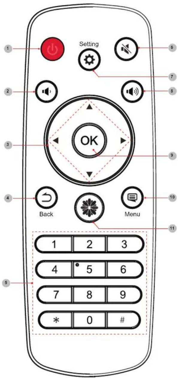
| Number | Description |
| 1 StandbyEnter /exit standby | |
| 2 Volume down (-) | |
| 3 ▲/ | Move focus up/down◄/►Move focus left/right |
| 4 Back | Back to previous menu |
| 5 Numbers | Input characters |
| 6 Mute | Activate/exit mute state |
| 7 Setting | Open the Settings menu |
| 8 Volume up (+) | |
| 9 OK | Confirm operation |
| 10 Menu | Call out function menu |
| 11 Home | Enter home page |
Battery replacement method
- Disconnect the battery cover from the remote control at the battery cover buckle and open the battery cover.
- Insert two AAA 1.5V alkaline batteries. Note that the positive (+) and negative (-) terminals of the batteries must match the positive (+) and negative (-) terminals in the battery case.
- Close the battery cover from top to bottom until it is fully aligned with the remote control.
Precautions
- If the remote control is not working properly, is unstable, or can't control the device, please replace the batteries.
- If the remote is not used for a longer period of time or the battery is exhausted, remove the battery. (Waste batteries pollute the environment and must be handled properly.)
- In order to achieve the best remote control effect, please point the black launch window on the back of the remote control at the indicator light of the device.
- Discard batteries in a designated disposal area. Do not throw them into a fire.
- Remove old batteries immediately to prevent them from leaking into the battery compartment.
- Battery chemicals can cause a rash. If the batteries leak, clean the battery compartment with a cloth. If chemicals touch your skin then wash it immediately.
- Do not mix old and new batteries.
- Do not mix alkaline, standard (carbon-zinc) or rechargeable (NiCd, NiMH, etc.) batteries.
- Do not continue using the remote if it gets warm or hot.
- If any of these issues occur, call our Support Center immediately on the support website.
Effective range
- Remote control distance: The distance from the front of the remote control is valid within 8m.
- Remote control angle: With the remote control receiving window of the device as the apex, the angle in horizontal direction at the distance of 6m is at least ±30^ , and the angle in vertical direction is at least ±15^ .
3. Installation Guide
3.1 Precautions for Installation
As shown in the figure below, leave a ventilation space around the device.
When mounted on the wall:
- Do not install the device as shown below.
Hinder air circulation
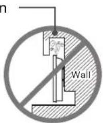
Insufficient ventilation will overheat the device and may cause damage to the device and even fire.
3.2 Wall Mount Kit Specifications (VESA)
NOTE: Please follow the instructions in the wall mount installation guide to install the wall mount or mobile mount bracket. If attaching to other building materials, please contact the nearest dealer.
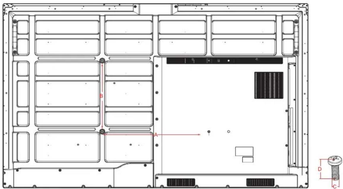
| Model VESA Spec. (A × B) Standard Screw (C × D) Quantity | |||
| 65WR6BE | 600 × 400mm M8 × 25 4 | ||
| 75WR6BE | 600 × 400mm M8 × 25 4 | ||
| 86WR6BE | 1000 × 400mm M8 × 25 4 | ||
NOTE: Do not use screws that are longer than the standard dimension, as they may cause damage to the inside of the display.
3.3 Installing the OPS (Optional)
Before installing and operating OPS, it is required to carefully read the instructions that come with the OPS computer and this instruction manual.
Installation Sequence
- The touch screen is set to the "off" state, and the indicator light is off.
- The operator wears anti-static gloves and takes out OPS computer.
- Assembly steps for OPS computer:
(1) This product is compatible with OPS-C Plus interface computer, and assembly instructions are as follows:
Note: Different models of touch screen and computer brackets have different shapes, but the assembly method is the same.
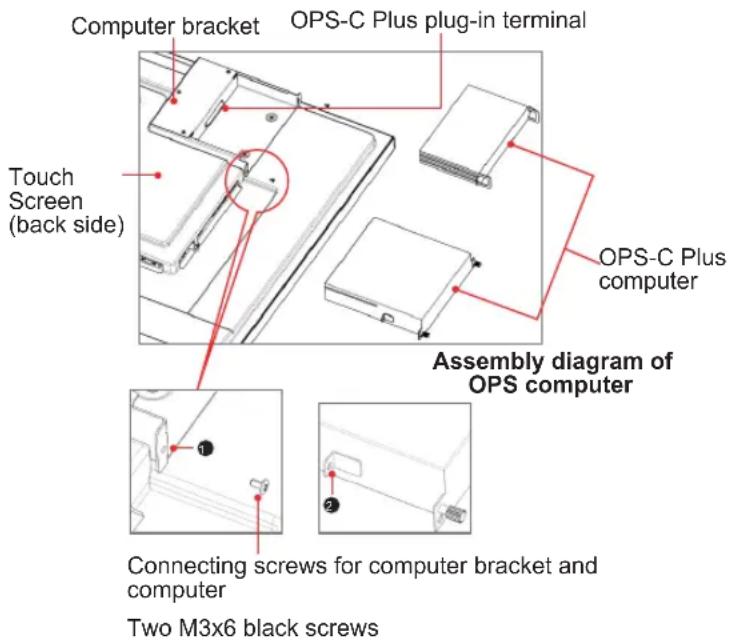
① is located at the computer bracket and the connecting screw of computer, which can be matched with ②.
② It is the hanging nose, where the OPS-C Plus computer is assembled with fastening screws. There are a total of two hanging noses, which are placed in the OPS-C Plus computer package as an accessory and there is need to assemble them on the OPS-C Plus computer in advance.
Before assembling the computer, please check the shape of OPS-C Plus plug-in terminal, which should meet the requirements in the following Figure:
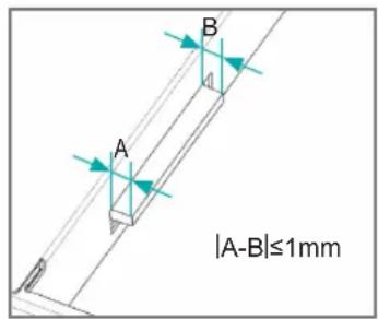
Instructions for OPS terminal assembly
tolerances
(2) Instructions for assembly routes:
a. Place the touch screen vertically or place the touch screen face-down stably. Make sure there is enough room for operation around the computer bracket on the back of screen.
b. Remove the M3x6 screw reserved at ① for standby application.
c. Insert the OPS-C Plus computer into the computer bracket along the route until ② and ① are in close contact.
d. Apply spare screws M3x6 to fasten the computer (some computer models come with screws that can be used directly), tightening torque: 0.5 N·m<M<0.8N·m.
(3) The pattern after assembly is as follows:
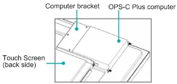
Schematic diagram after the assembly of the OPS-C Plus computer
(4) Precautions after assembly:
a. After the computer is installed, ② and ① should be closely fitted (same on the left and right sides).
b. Screws are firmly and securely fastened. The computer would not be able to move or shake.
- After the above steps are completed, the screen can be switched on. After startup, the OPS computer is started, and the operating system interface is performed to confirm that there is no abnormality. The installation is completed.
3.4 Installing the Camera (optional)
Camera:
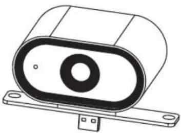
natural_image
Technical line drawing of a cylindrical electronic component with mounting base (no text or symbols)Installing the Camera
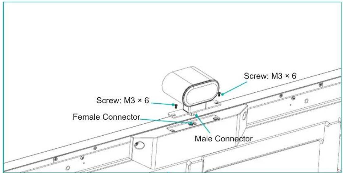
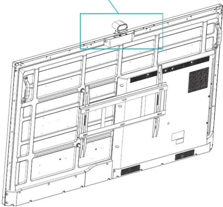
Step 1: Make sure the device is powered off. Press the power switch [ I O ] of the device to [ O ] (Some models have no power switch).
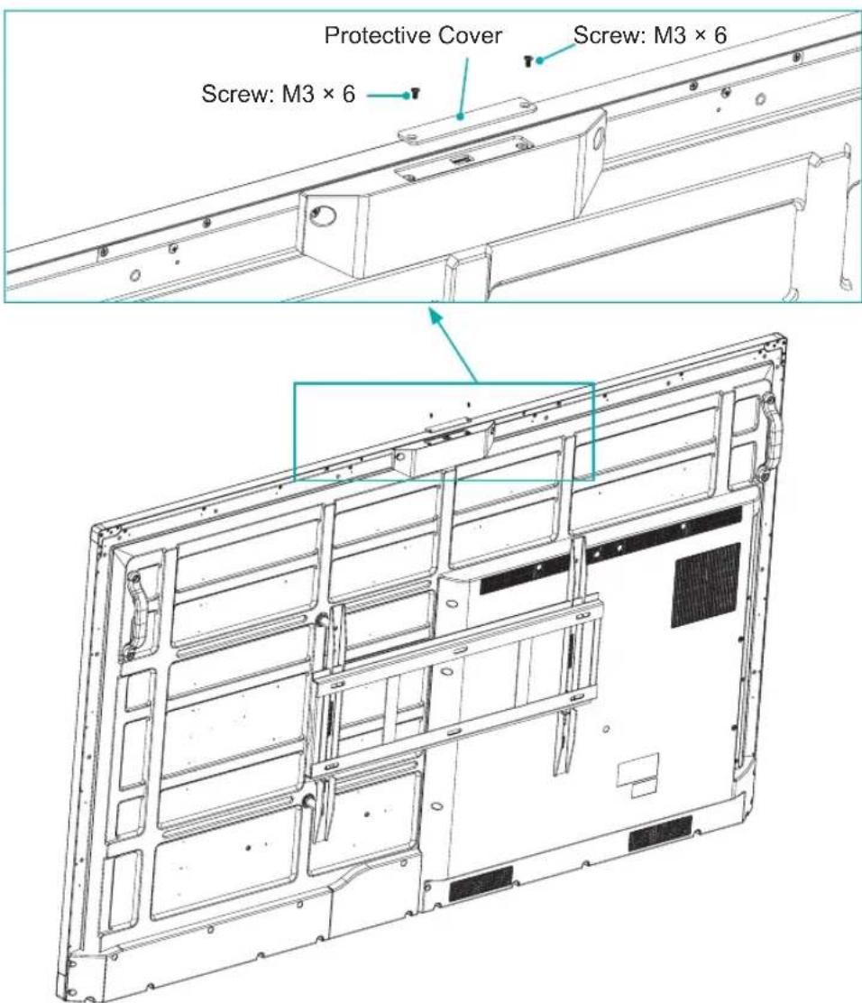
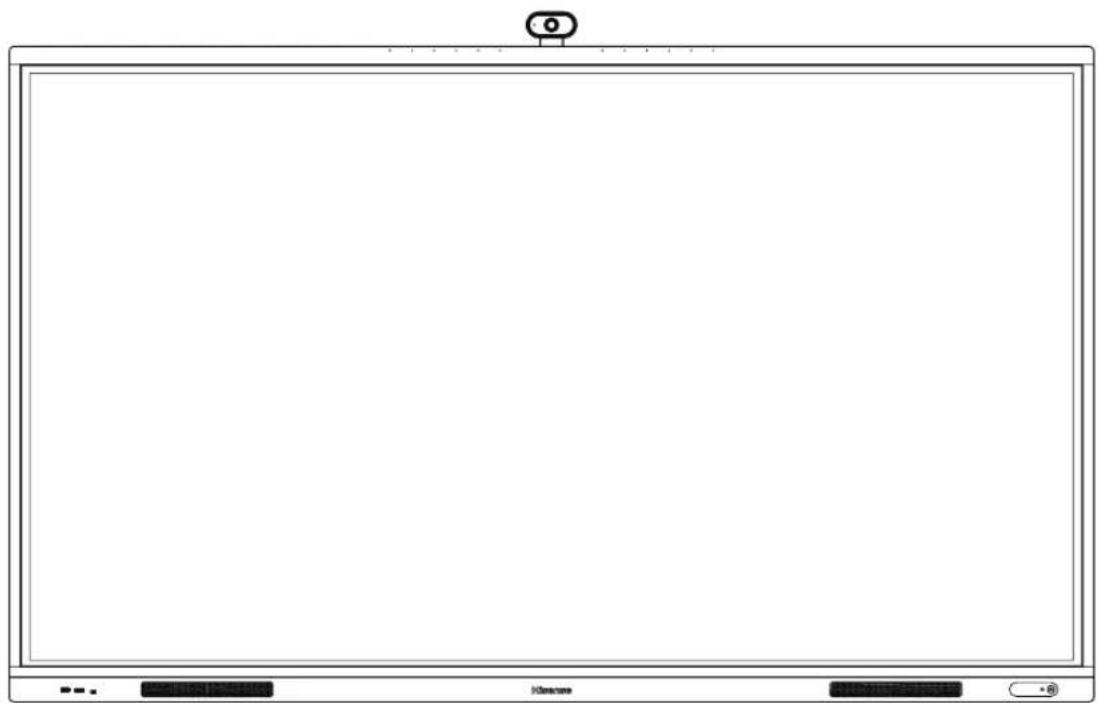
Step 2: Insert the male connector into the female connector of the camera, and fix it with two screws;
natural_image
Technical line drawing of a computer monitor chassis showing internal components and mounting brackets (no text or symbols)Installation Guide
natural_image
Blank whiteboard with a small circular icon at the top (no text or symbols)Making Connections
4. Making Connections

| Number | Port Description | |
| 1 AC | Switch Turn on/off AC power supply | “I”=Power on, “O”=Power off |
| 2 AC | INPUT AC power input | |
| 3 DIGITAL AUDIO OUT | Connect to power amplifier via coaxial port, then connect power amplifier to speaker | |
| 4 DP | DP signal input, connect to a PC with DP output | |
| 5 SERVICE For factory commissioning, no other functionality | ||
| 6 HDMI IN HDMI signal input | connect to a PC with HDMI output port, set-top box, or other video device | |
| 7 TOUCH Touch signal output to an external PC | ||
| 8 | HEADPHONE | Audio out to Headphones |
| 9 | HDMI OUT | HDMI signal output, connect to an external device with HDMI input port |
| 10 | USB 3.0 | Connect USB devices such as hard disks, keyboard, mouse, etc. [5V DC/1A] |
| 11 | RS232 | Serial interface, used for transfer of data between devices |
| 12 | USB 2.0 | Connect USB devices such as hard disks, keyboard, mouse, etc. [5V DC/0.5A] |
| 13 | LAN | Standard RJ45 Internet connection interface |
NOTES
- RS232 port: It is the serial control of the device and is needed to carry out secondary development according to user's protocol.
- Some external devices can't be connected to this device due to individual differences. In this event, please replace appropriate signal cable or add the patch cord that matches the port.
- Please do not turn on/off the device continuously and quickly since power failure and system processing take time. Otherwise, the device may work improperly.
Making Connections
Connecting to external audio device
Digital audio output: connect to a power amplifier via the coaxial port, then connect th power amplifier to a speaker.
flowchart
graph LR
    A["Device port"] --> B["Power amplifier"]
    B --> C["Speaker"]
    B --> D["Coaxial port"]
    D --> E["Connect the power amplifier to a speaker"]
Connecting to a DP interface device
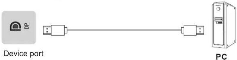
flowchart
graph LR
    A["Device port"] --> B["USB cable"]
    B --> C["USB cable"]
    C --> D["PC"]
NOTE
The supported signal formats of the DP port are outlined in Chapter 8 Appendix.
Lower version DP cables may cause screen flashing or no displaying, please try to use cables in latest version and high quality.
RGB signals may occur low quality situations in low or high brightness mode. To adapt the picture quality, you can press the ⚙ Settings button on the remote control, select Dynamic Range in the Picture menu, and then select All.
Connecting to an HDMI input
Connect the HDMI input connector of the device to the HDMI output port of an external device.


NOTE
The supported signal formats of the HDMI port are outlined in Chapter 8.1 Specifications.
Connecting to an HDMI output
Connect the HDMI output connector of the device to the HDMI input port of an external device.


NOTE
When using it as a screen monitor, carefully read the precautions.
Connecting to a Touch interface device
It is the touch screen interface used for an external PC. In both the HDMI and DP channels, the device is used as a touch unit by default
When connecting, USB cables no longer than 1 meter should be used to connect with the external PC.

Using an external interface with the touch screen and selection of the touch unit
This device has a Touch port. When using an external PC as the touch unit and signal source unit, connect USB ports of the device and PC with a USB cable (both ends are male connections), connect the PC to the device with a signal cable (HDMI and DP cable), and switch the signal source to that channel. At this time, the touch screen can be connected to the corresponding unit, and the touch screen can be used to perform touch operations on the unit.
On the home page, the device is used as the touch unit. In HDMI, OPS and DP channels, the device is used as the touch unit by default. When the external unit is connected and powered on, and the USB cable is connected to the external unit (OPS does not need a USB cable), the touch unit is changed to the external PC.
To operate the device, use the five-point touch method to call out the soft control menu and operate the device. Afterwards, tap any area outside the soft control menu of the device to hide the soft control menu. Then you can continue to operate the external PC, and the current channel is set as the touch input channel.
HEADPHONE Connect headphones for audio out of the screen.
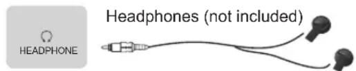
Device port
ATTENTION
Excessive sound pressure from earphones and headphones can cause hearing loss.
NOTE
Please make sure that the headphones are without microphone function, as it may not be supported.
Connecting to a USB interface device
The total current of all the USB output ports of the device when connected to external devices at the same time must not exceed 4800mA, or else the device failure caused by overcurrent is not covered by the warranty.
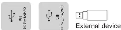
Device port
NOTE
This device is connected to wireless keyboard and mouse devices. If there is any insensitivity phenomenon during use, try changing the wireless receiver to another USB port, or using a USB extension cord to connect the wireless receiver to enhance the receiving range.
Connecting to a network
Enter the Settings menu and select the Network item.
WIFI
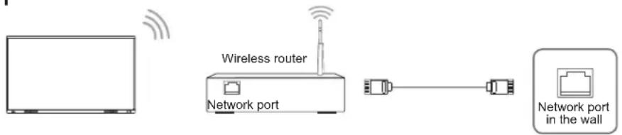
The device can receive network signals directly through a Wireless router
- The available wireless network list is automatically displayed when WIFI is selected.
- Select an available network, enter the password, and tap Connect. If the selected network is not encrypted, the device can connect directly.
- If the required network is not displayed in the list, tap Refresh to display more networks. If the network SSID is still not displayed after this operation, tap Add Network and enter the network name manually, select the corresponding encryption method according to router settings, enter the password, and tap Confirm.
Ethernet

flowchart
graph LR
    A["LAN"] --> B["Router"]
    B --> C["Network port output"]
    B --> D["Network port input"]
    C --> E["Network port in the wall"]
Device port
- Ethernet: auto
The device automatically obtains an IP address and connects to the network. If the IP address fails to generate or does not allow connection to the internet, repeat the operation again or choose Ethernet: manual.
- Ethernet: manual
Manually enter the IP Address, Subnet Mask, DNS Server and Gateway.
Connecting to the OPS interface device
OPS (Open Pluggable Specification) is the interface specification developed by INTEL which is applicable to embedded computer module products. With this interface, the screen can be connected to the device in compliance with OPS interface specification, which is short for OPS module. Recommended adaptable OPS modules are S02BDS58811E, S02BDS5A811E and S02BDS7AA21E, available separately as accessories.
This product can provide the OPS module with 19V ± 0.5V (3.4A MAX) power supply.
NOTE
After installing the OPS module, when the signal source is in the OPS source channel, the device touch screen regards OPS as the touch unit by default. After the TOUCH cable is connected with an external computer, the external computer is used as the touch unit. At this time, the signal source should be switched to the channel of the external computer for using the touch functionality.
It is recommended to choose and purchase OPS already certified by Hisense, with the i5/i7 latest generation processor, 4G memory, 128 GB solid state drive or above.
Only OPS modules compatible with the size of the device OPS should be installed. The size of OPS refers to the following figure:
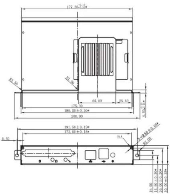
- Switching on/off the OPS
After inserting OPS to the device, turn on the device, change the signal source to enter the OPS and stay on the OPS system interface. When turning off the device, use the standby button to go into standby mode, the OPS module is switched off, and then shut off the device.
5. Getting Started
Power On/Off
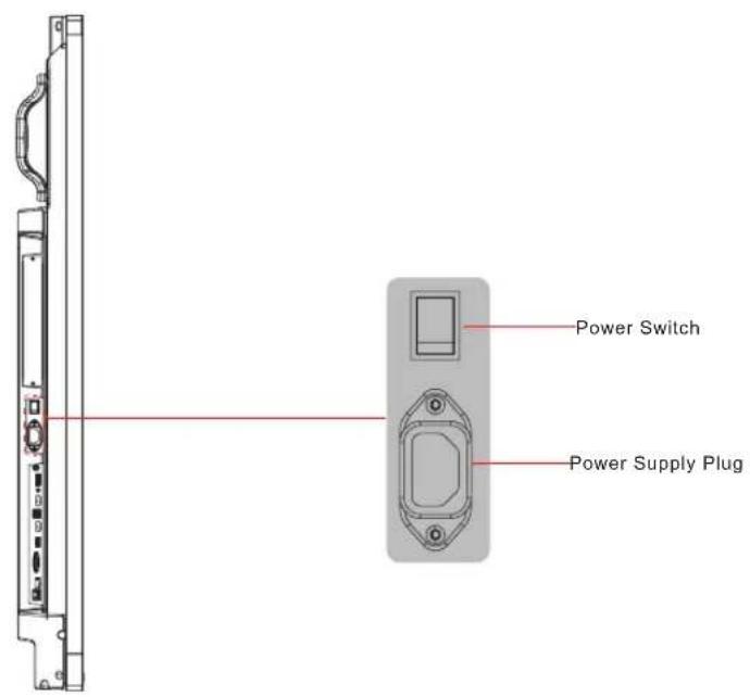
- Connect the power cord of the device to a 100V to 240V AC outlet.
- Press the power switch [IO] of the device to [I] (Some models have no power switch).
- Press the standby button [ ☑ on the remote control in the power on state to switch the device to standby; to resume the device, simply press the standby button [ ☑ on the remote control again.
- To turn off the device, press the power switch [I O] of the device to [O].
Note:
- When the AC power is turned off, wait at least 5 seconds before turning it on again in order to prevent problems of the device.
6. Using the Vision Board
6.1 Initial Launch Setup
When first turning on the Vision Board, an initial setup wizard will launch.
Select the language (default [English]), and then proceed to [Next Step]:
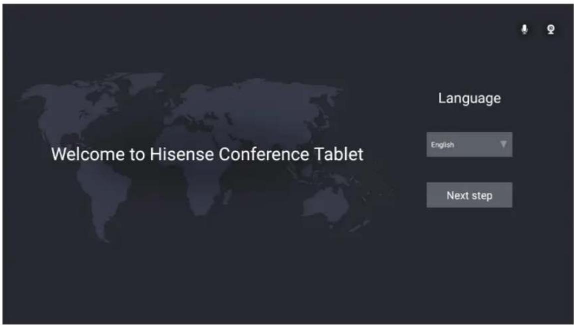
Read the user agreement and [Accept]. If you do not accept, you cannot proceed to the next step.
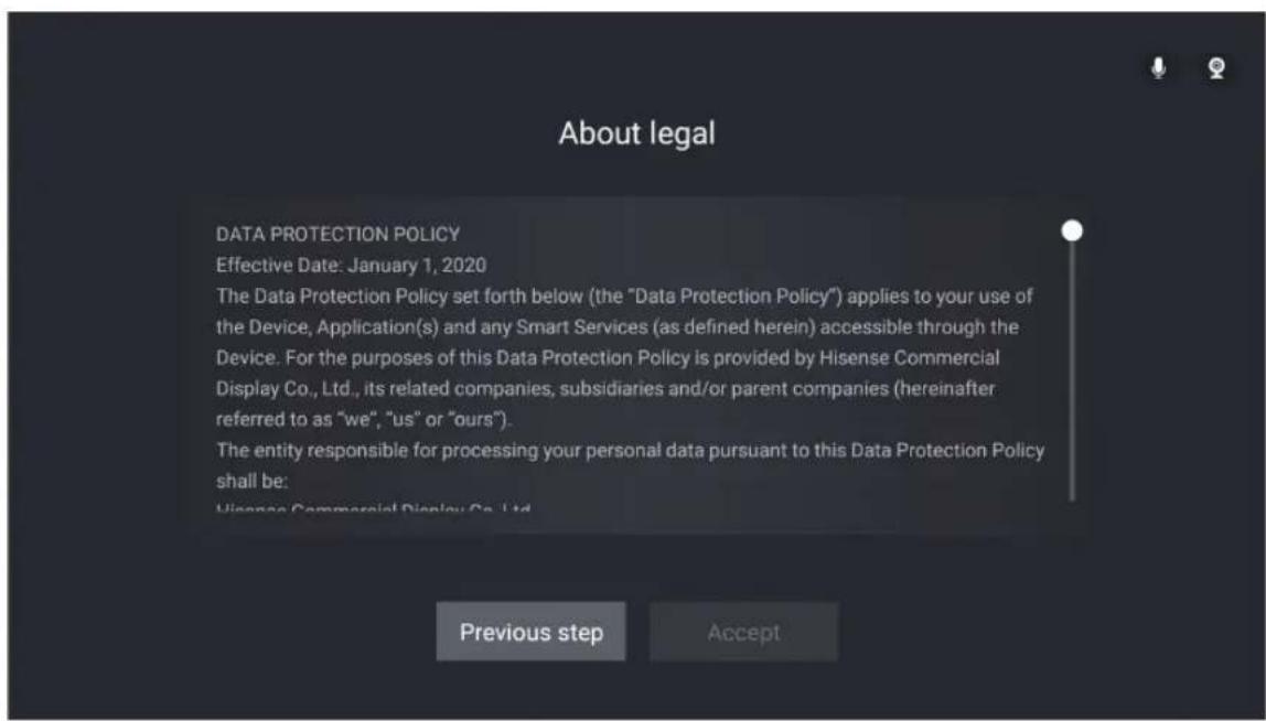
Using the Vision Board
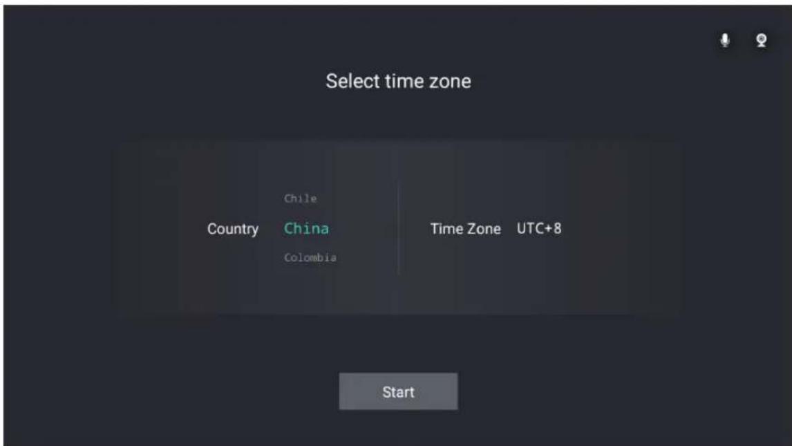
After accepting the user agreement, enter the Time Zone Selection page;
6.2 Homepage and Taskbar
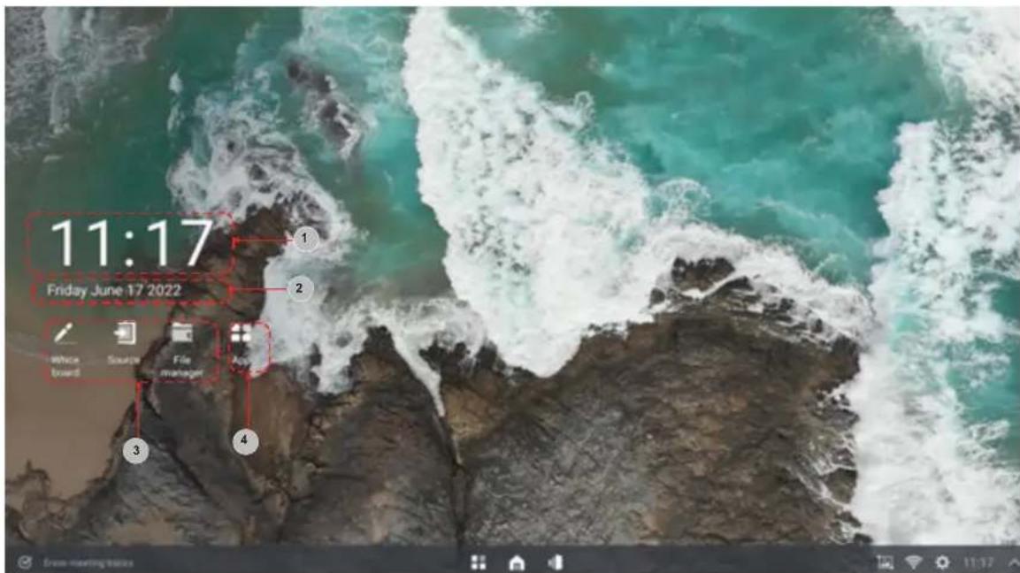
- Homepage
Contents displayed on the home page: 1. System time, 2. System date, 3. Core Apps, 4. Menu containing all installed apps
In the homepage state, tap the screen to call out the Task Bar.
In the case of non-homepage, swiping up from the bottom center of the screen to call out. When switching scenes/touching other parts of the screen/not touching the screen for more than 15 seconds, it will minimize downwards again.
Using the Vision Board
- Taskbar
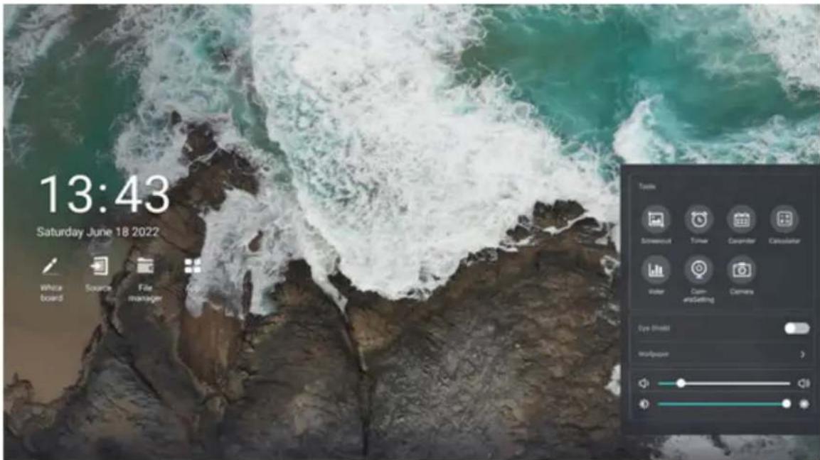
It is possible to choose whether to erase traces of use in the super task bar. This action can close all apps simultaneously, and clear any contents. A saved file can't be deleted, and if a file needs to be deleted, this must be deleted in the file manager.

Other options allow to open the application list, return to the home page, call up the task view and perform corresponding operations, like quick launching tools, checking the brightness, volume and network status..
6.3 Using Gestures
6.3.1 Five-finger Menu
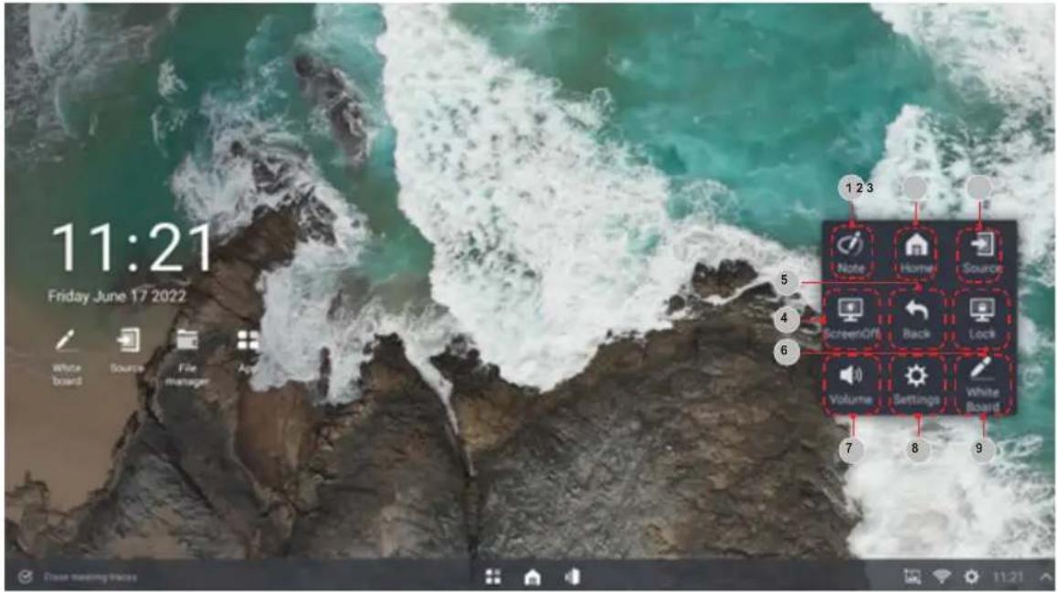
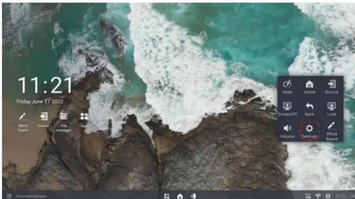
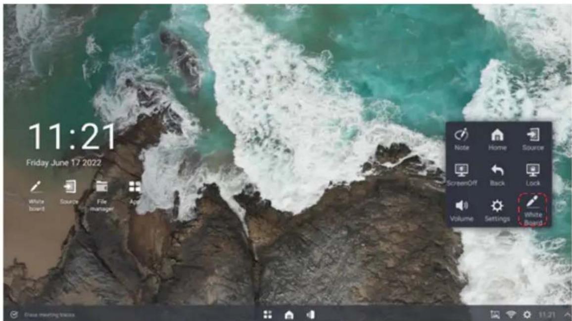
In any scene on the screen, touch the screen with five fingers to call up the shortcut menu.
| Number | Function Description | |
| 1 | Annotation Annotations (whiteboard) possible on any source | |
| 2 | Homepage One-click to return to the Android homepage | |
| 3 | Signal source Open the list of accessible sources | |
| 4 | Screen off Turn off the screen backlight. During this all programs continue to run. | |
| 5 | Return Return to the previous operation | |
| 6 | Lock screen The screen is locked and it can't be operated by touch or remote control | |
| 7 | Volume | Open the volume adjustment interface |
| 8 | Setting | Open the setting page of the whole machine |
| 9 | Whiteboard | Open the pre-installed whiteboard software |
Using the Vision Board
6.4 Settings
How to enter settings?
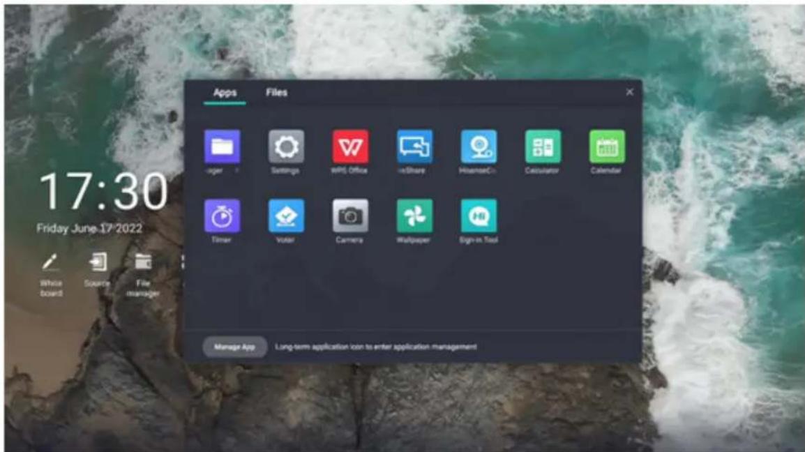
- Method 1: Open the settings in the list of all apps to enter the system settings menu of the whole machine.
- Method 2: Click settings in the five-finger touch menu to enter the settings menu of the whole machine.
Using the Vision Board
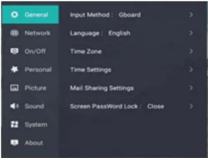
| General | Input method Switch input methods | |
| Language settings Switch languages | ||
| Time zone setting Switch time zone | ||
| Time and date settings Set time and date | ||
| Mail sharing settings Set default mailbox | ||
| Camera Camera settings | ||
| Microphone Microphone settings | ||
| Password lock Add password lock for the device | ||
| Network | Wireless network Set up the wireless network | |
| Wired network Set up the wired network | ||
| Wireless hotspot Turn on the wireless hotspot | ||
| Wireless display Turn on the wireless display function | ||
| Network details View current network details | ||
| Bluetooth Set up Bluetooth | ||
| Network diagnosis Detect network status | ||
| Power on/off | On channel | Select the signal source loaded automatically after startup |
| Fast on/off | Fast on/off settings | |
| Timed on/off | Set time for timed on/off | |
| No signal standby | Set time to automatically enter standby state after no signal | |
| On state | Set on state | |
Using the Vision Board
| Personal | Customize Launcher background | Change logo and background |
| Customize the boot screen | Change the boot screen | |
| Standby animation switch Turn | Turn on/off standby animation | |
| Screen saver switch Turn | on/off screen saver | |
| Customize screen saver Change screen saver | ||
| Timed screen saver Screen saver timing | ||
| USB file transfer permission | Turn on/off USB file transfer permissions | |
| Type-C sharing Type-C shared switch | ||
| Voice assistant Voice assistant switch | ||
| Picture | Picture mode Change picture mode | |
| Eye protection mode Eye protection mode switch | ||
| Intelligent backlight adjustment | Intelligent backlight adjustment switch | |
| Local light control Local light control switch | ||
| Advanced settings | Manually adjust backlight, brightness, etc. | |
| Ultra-low delay mechanism | Ultra-low delay mechanism switch | |
| Reset all picture settings Reset all pictures | ||
| Sound | Sound mode | Change sound output mode, conference mode/standard mode |
| Dolby Atmos Dolby sound switch | ||
| Output device | Change the sound output device | |
| Audio output format | Change the sound output format | |
| Reset all sound settings | Restore default sound settings | |
| System | Touch input channel | Change the touch input channel |
| USB settings | Change USB settings | |
| HDMI version Revise | HDMI version | |
| HDMI output settings | Revise HDMI output settings | |
| LAN sharing | LAN sharing switch | |
| About | Information of the machine | View the information of the machine |
| Machine name | Change the name of the machine | |
| Application management | Manage all applications | |
| System update | Update system version | |
| Restore factory defaults | Restore factory defaults | |
6.5 White Board
6.5.1 Open the White Board
- Click the whiteboard icon on the home page;
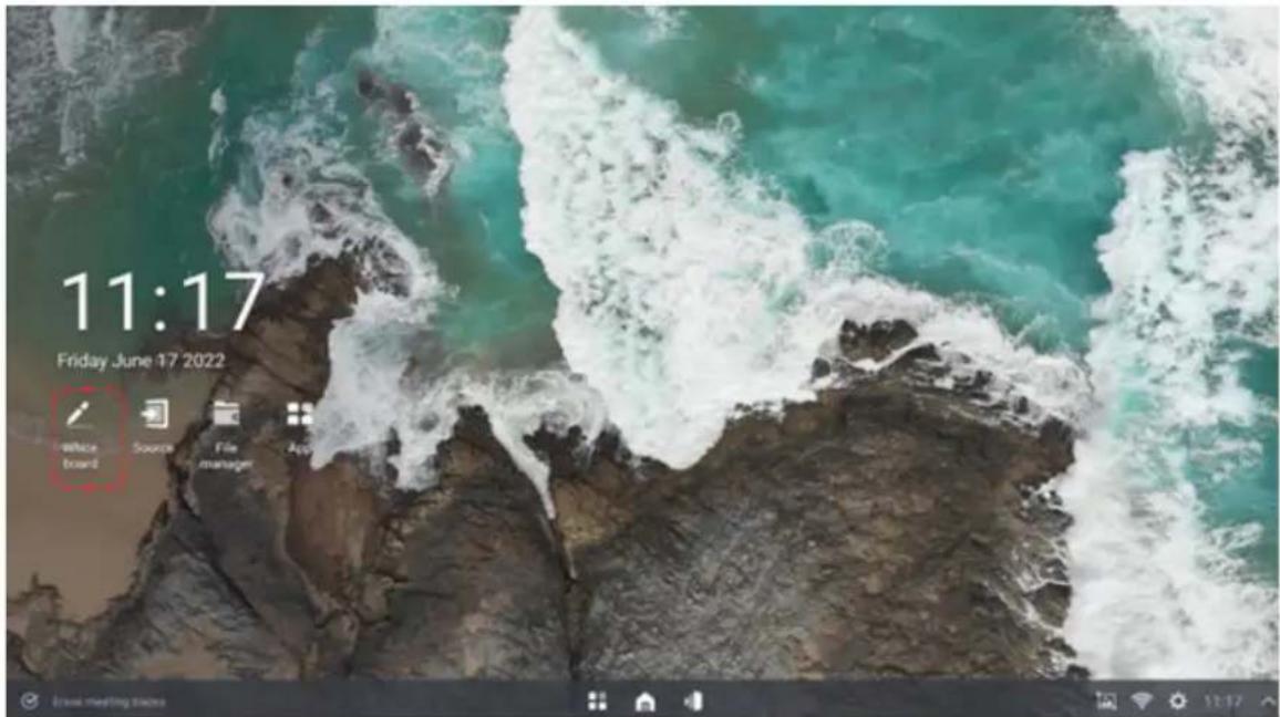
- Select whiteboard from the five-finger menu;
Using the Vision Board
- Click the whiteboard icon on the home page;
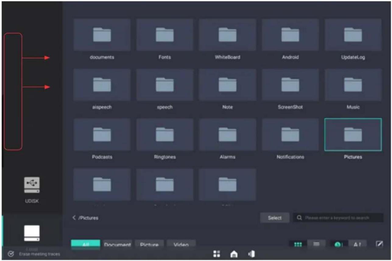
- In the application, after clicking on screen with your finger, a small black bar will appear in the middle of the left side of the screen and at this time, hold the small black bar and pull it to the right side till reaching 1/3 of the screen, then release it to easily call up the whiteboard for display.
- If the application supports split-view mode, the whiteboard and this application shall be displayed in split screen.
- If the application does not support split-view mode, the whiteboard will be displayed in full screen.
- Pick up the pen to wake up whiteboard function.
Pick up the touch pen from the machine to automatically wake up the whiteboard.
Note: It only functions in Android main interface, but not in OPS and application interface (except for widgets).
Using the Vision Board
6.5.2 Main Interface
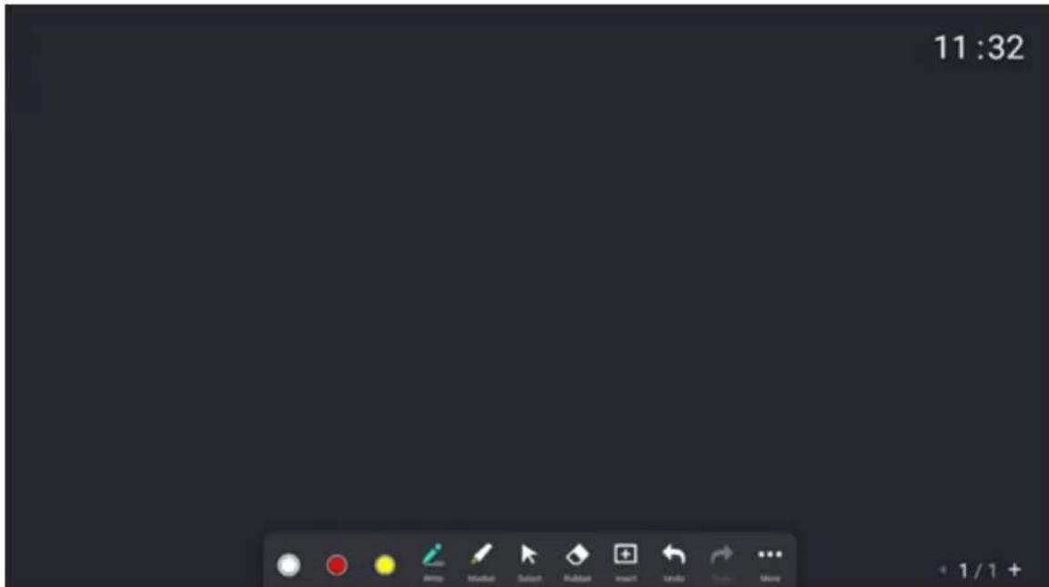
6.5.3 Handwriting
- Custom pen color
- Sizes of three pens
-
Pen written mode
-
Off - it supports writing with finger, pen tip and cap.
- On - it only supports writing with the pen tip. Fingers & pen caps have the eraser function.

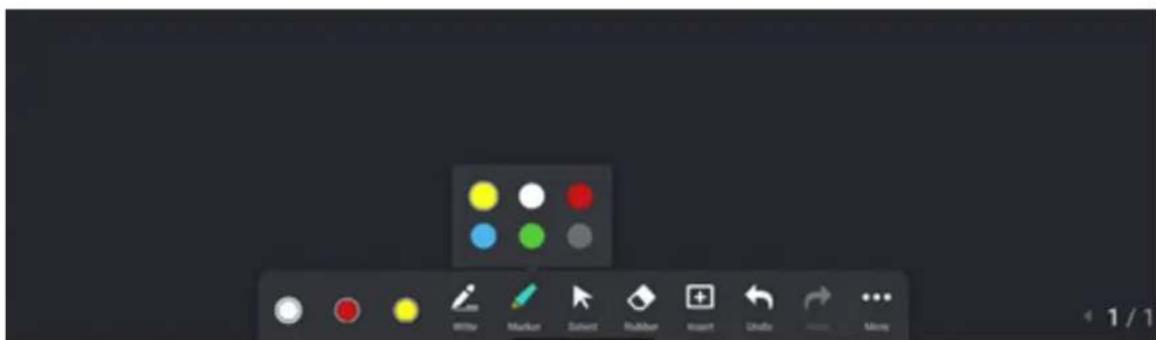
6.5.4 Highlighter Color Selection
Highlighter supports six colors. The default color is yellow.
6.5.5 Erase Options
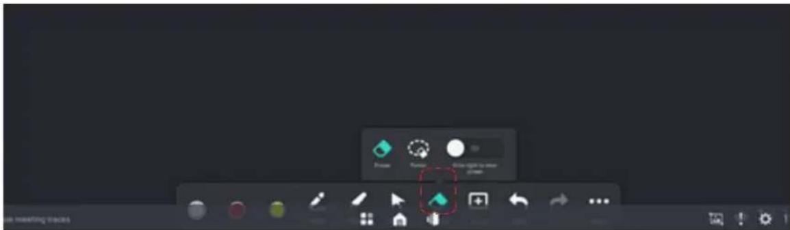
It is possible to select Eraser, erasing by selection or erasing the entire screen at once
- Eraser: This supports palm erasing. After the palm touches the large screen, it is recognized as an eraser. Users may use it to erase partial contents.
- Circle erase: You can select an area to erase contents in the area at one time.
- Clear screen: Slide this button to erase all contents on the screen at once.
6.5.6 Insert Files
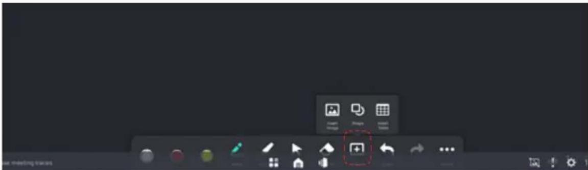
- Insert pictures
(1) Multiple pictures can be inserted in whiteboard writing
(2) The inserted picture can be deleted after being selected, and a dialog box will pop up to confirm the deletion.
(3) The inserted picture supports rotation and copying after selection
(4) A maximum of 10 pictures can be inserted into one page. The actual maximum number of pictures supported depends on the available memory of the all-in-one machine and the resolution of inserted pictures, but the maximum number is not more than 10. When there is insufficient memory and cannot be inserted, the message "Insertion failed, insufficient memory" will be displayed.
(5) The inserted pictures are stacked in the middle of the whiteboard. The inserted pictures can be selected by tier. By default, click to select the topmost image
- Insert graphics
Insert normal graphics
(1) Select Insert Graphics to display a list of insertable graphics. The graphics that can be inserted currently include a circle, arrow, rectangle, square, rhombus and parallelogram.
(2) After clicking Insert Graphics, insert the graphics of the default size, and the graphics will be displayed in the middle of the canvas. If continuously clicking the graphics, the graphics will be arranged from bottom to top, and sorted according to the insertion sequence.
(3) After inserting graphics, it supports copying, deleting, and rotating the selected graphics. At the time of rotation, the rotation angle should be displayed. When it is 0, 90, 180, and 360 degrees, there is an automatic correction effect within the range of plus or minus 5 degrees.
Insert smart graphics
(1) Enable the single-person writing mode and enable smart graphics.
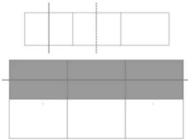
(2) Smart graphs can be recognized according to gestures. When it is recognized as a rectangle, table insertion can be performed according to gestures. Elaborate on the cutting of tables.
(3) In smart graphics mode, both smart graphics and standard graphics can be inserted at the same time. When smart graphics mode is turned off, only standard graphics can be inserted.
Using the Vision Board
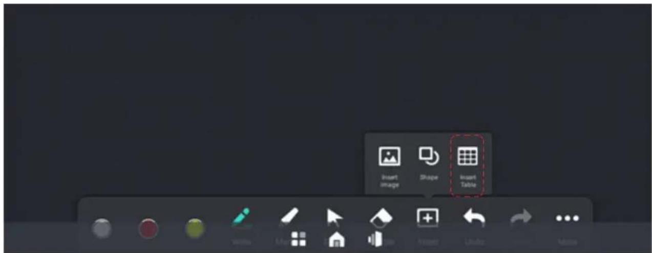
- Insert tables
Insert directly through smart graphs or tables.
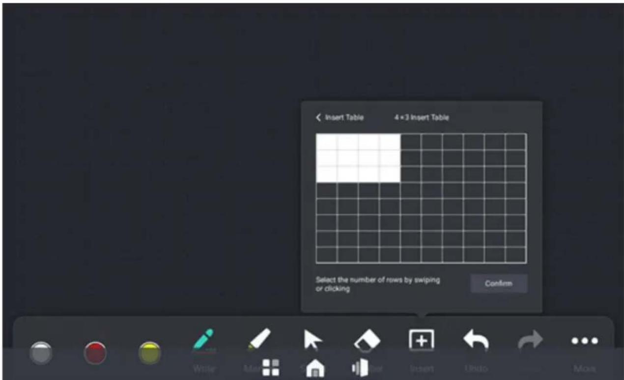
- By clicking Insert Table, the user will automatically enter the insert table mode, and be able to select the number of rows and columns to be inserted. The default number of rows and columns is 4 (columns) by 3 (rows), however, up to 10 (columns) by 8 (rows) can be selected at a time in the check box.
2.
Using the Vision Board
- After inserting the table, rows and columns can be added or deleted.
Use intelligent gestures or shortcuts for row and column addition and deletion to continue inserting tables. The final number of rows and columns of table is set to 20*20.
natural_image
Pure geometric diagram with rectangles and a central crosshline, no text or symbols present6.5.7 Gesture Description
Roaming: The display screen can be expanded infinitely through gesture operations, and the current page content moves in the direction of gesture.
Zooming: The display content can be zoomed in and out evenly from the center to the surrounding of screen by gesture operation, and zoomed in and out by gesture touch.
Erase: (1) The user's palm touches the screen, and the screen displays the board eraser icon.
(2) When the palm moves, the eraser icon moves with it, and the annotation intersecting the moving track of the eraser icon and the screen is deleted.
(3) The palm leaves the screen, and there is no contact for more than the specified time (confirmed according to the experience). The erasing process ends and switches to the writing state.
Select: Click to select the object. After selection, you can copy, delete, rotate and other operations on the object.
6.5.8 More Features
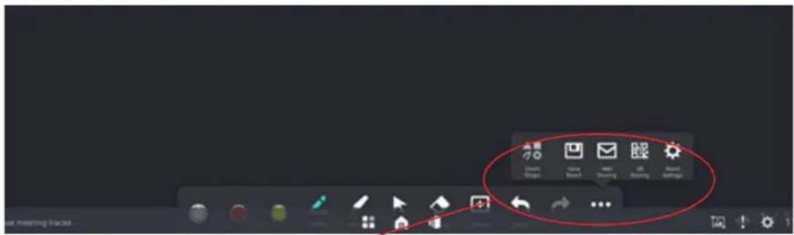
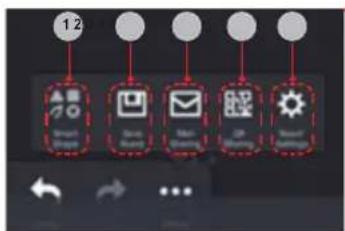
| 1. | $mart graphics |
| 2. | saving |
| 3. | email sharing |
| 4. | QR-code sharing |
| 5. | whiteboard setting |
- Whiteboard Sharing
In the whiteboard interface, it is possible to share by email or QR code through the share button.
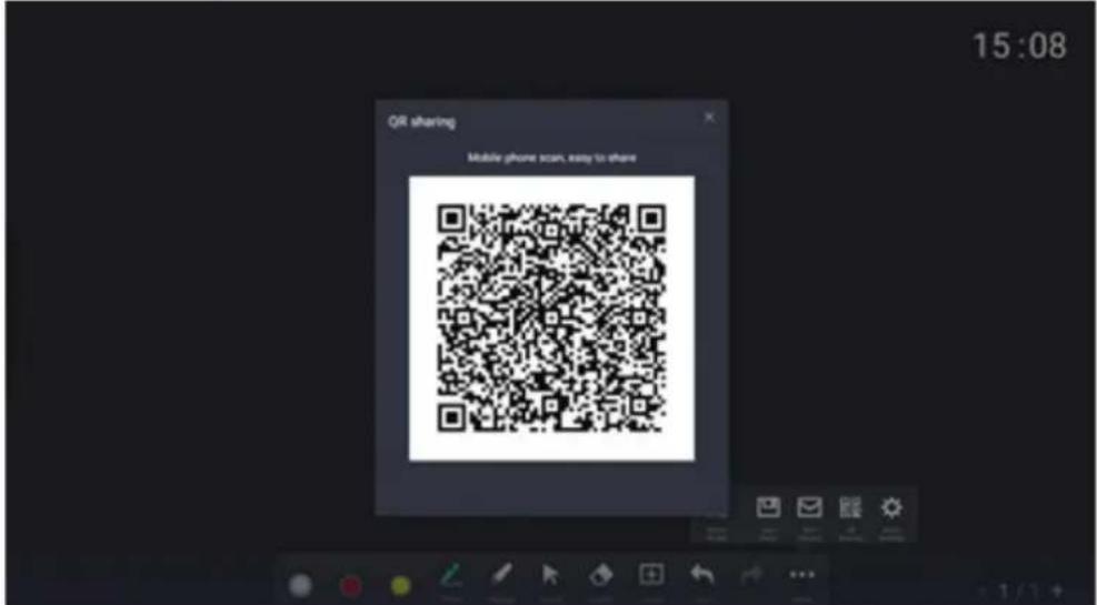
QR code
When sharing through QR code in the meeting whiteboard, only a PDF version of the file of the whiteboard saved can be shared. Users can enable sharing encryption when sharing with a QR code. After the QR code is enabled, the password needs to be entered and verified before the contents is able to be opened. The sharing encryption function can be turned off, and password modification is supported during the sharing process.
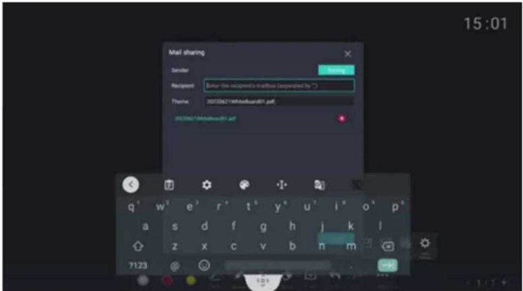
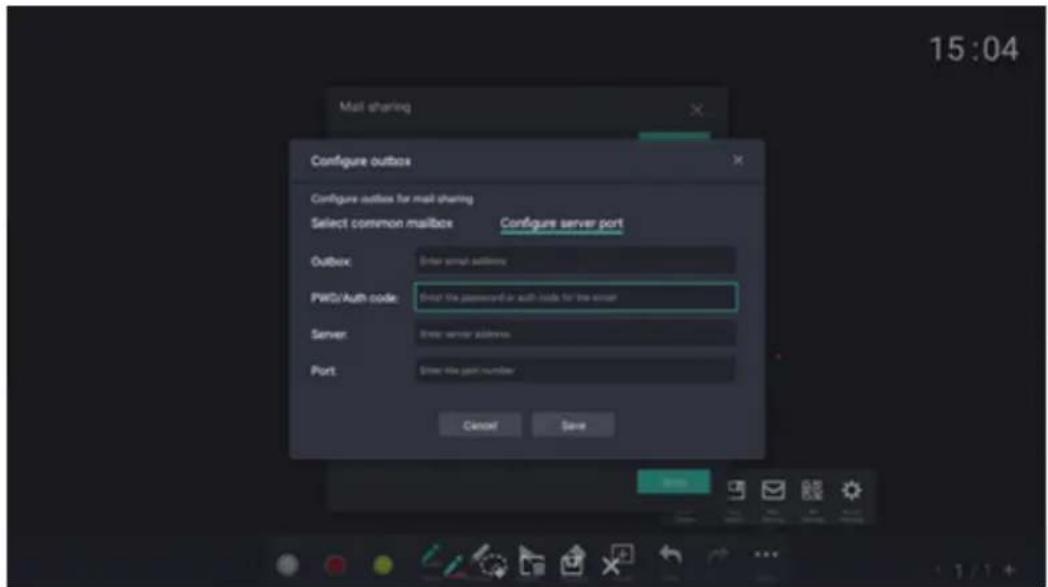
When sharing by email in the meeting whiteboard, only a PDF version of the saved whiteboard can be shared. The user needs to fill in the general email address and email password, and all of them are used to configure the outgoing email address for email sharing
Using the Vision Board
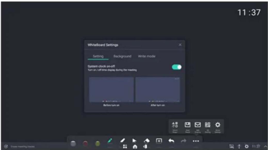
- Whiteboard Settings
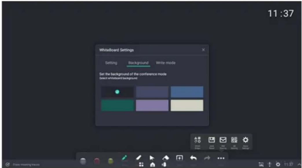
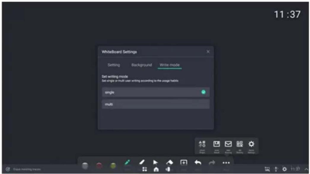
Personalized settings are available for whiteboards:
(1) Background settings, supports the background switching of 6 preset whiteboard backgrounds;
Using the Vision Board
(2) Switch settings for single or multiple writing touch points;
(3) System clock - active or deactive the clock on the whiteboard page.
6.5.9 Page Tool

- Page addition: Add a new page after the current page, and the whiteboard screen will automatically jump to the newly added page.
- Delete: Click the delete button in the page overview to delete the current page.
- Page turning: Click the arrows to move to the previous page or the next page..
- Page index: Click to display the index thumbnails of all pages, as well as displaying the total number of pages. Users can click any page to switch the whiteboard to the selected page, or click the delete button to delete the selected page.
• Page order adjustment: Click and drag the page to adjust the page order.
6.5.10 Side-pull Whiteboard
The whiteboard can be pulled out directly from the left;
Only works when an application is running. In the home menu, side swiping does nothing.
When an application is running on the main interface and such application supports split screen, the whiteboard will be directly split with such application. If the application on the main interface does not support split screen, the suspended state of side-pull whiteboard will be determined by default.
6.6 Source
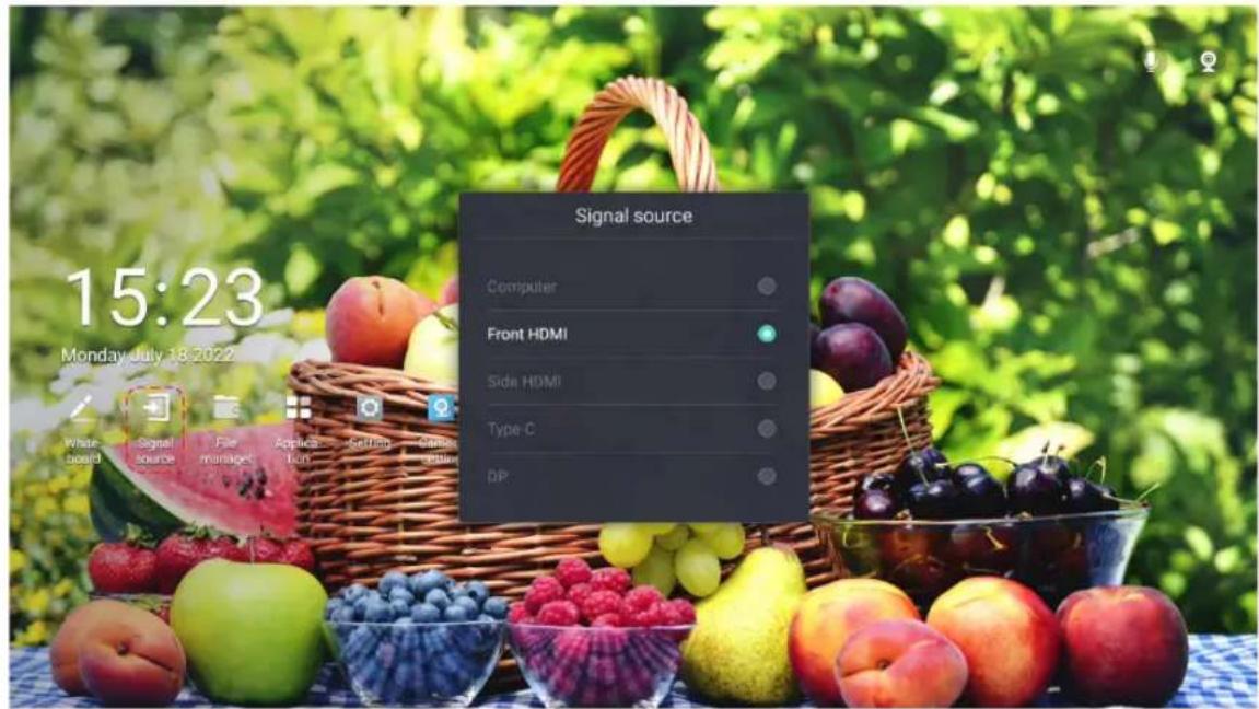
The list of signal sources can be opened through the "Source" icon found on the home menu and the five-finger menu. Select the signal source in the list to switch in real time. Physical signal sources that are not detected are displayed in gray font.
6.7 File Manager
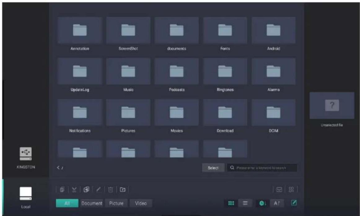
Click the "File Manager" icon found on the main menu and the apps list to enter the file manager interface to obtain the data stored in the local machine or external storage.
6.7.1 Document Management
Files are arranged according to certain sorting rules. Documents support forward and reverse sorting by name and date. If the sorting mode of reverse order is adopted, the folders shall be arranged after the files, as folders and files are sorted separately.
(1) Name sorting rule: Arrange in alphabetical order.
(2) Date sorting rule: The rule for sorting files by date: sorting according to the time of file modification, and sorting by the creation time of file when the file has not been modified.
(3) Sorting by time is the sorting mode by default of file manager. Time is reverse sorting by default, and name is sequential sorting.
6.7.2 File View
(1) Local storage is displayed by default when the file manager is opened. When a USB flash disk is inserted, click USB flash disk icon on the left to view the files on the flash disk storage.
(2) Text Display:
a. File icon: The file types that can be viewed by conference products need to be prompted by icons, and different types of files need to be distinguished by icons. For those files that do not support the format, there is need to adopt a uniform default icon.
b. Display file name: The displayed file name and the number of characters displayed in the file name are determined by the system. When the file name is too long and cannot be displayed completely, there is need for truncations and represented by ...
c. In the file manager, you can switch the display mode of files (folders), and support two display modes, i.e. thumbnail and list. Thumbnail mode is determined by default;
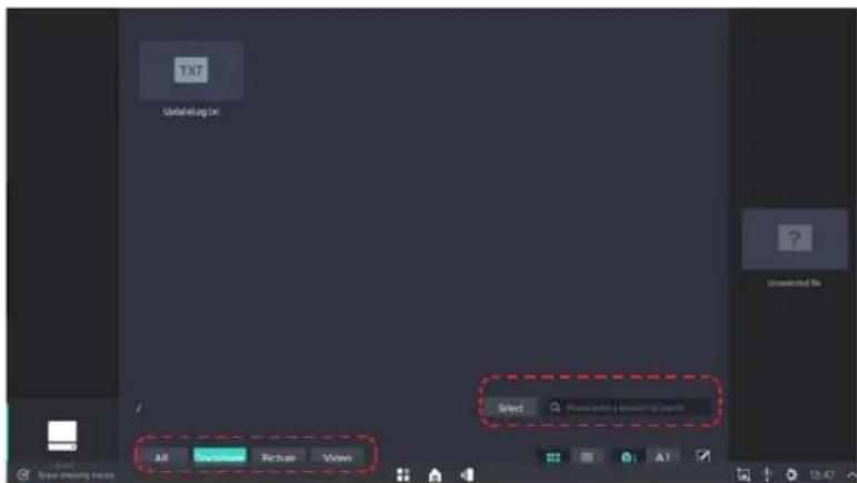
d. In the file manager, file classification view is supported, including all files, documents, videos, and pictures.
(3) Folder display
a. Displays the folder icon.
b. Display folder name: The displayed folder name and the number of characters displayed in the folder name are determined by the system. When the folder name is too long and cannot be displayed completely, there is need for truncations and represented by ...
(4) File viewing mode:
The mode of opening files by file manager is provided by the system. If the system contains multiple software programs that can open such file, users can select the mode of opening files.
6.7.3 File (folder) Copy
Users can copy files (folders) to other directories or USB flash drives, or copy files (folders) from USB flash drives to local storage directories
(1) After copying a file or folder, the user can select to paste into the directory as needed, and then the copying of file/folder is completed. If a file/folder with the same file name already exists in the directory to be pasted, there is need to create a copy file or a file with a different name.
Using the Vision Board
(2) Users can copy multiple files (folders) at the same time. If the replication fails, the copied files are retained and the replication process is aborted.
(3) When copying files in pictures, documents, audio and video, it cannot be pasted in the category. Instead, it is possible to select all the paths to paste.
6.7.4 Delete Files (Folders)
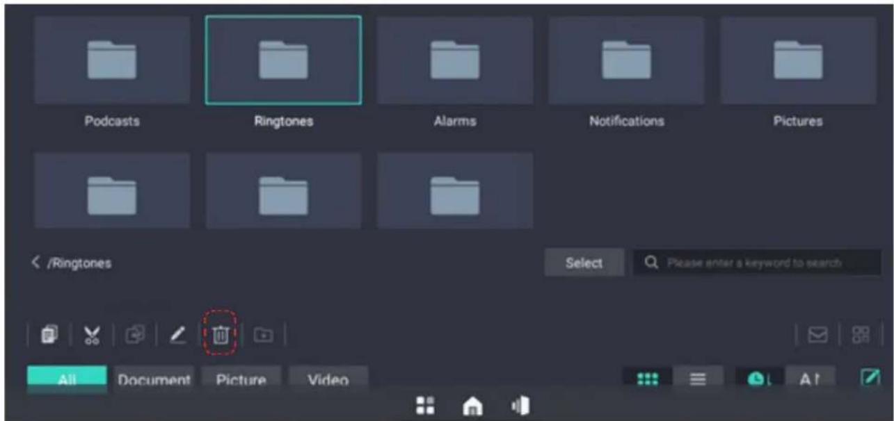
Users can delete files (folders) in the file manager through the file browser.
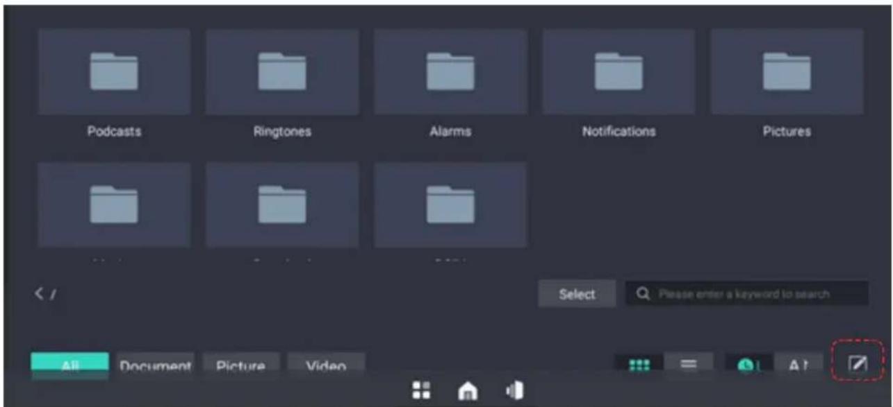
- Deletion of files one by one: After the file is selected, select the edit button, call up the operation bar, select delete. If you are sure to delete the selected file, select OK.
Using the Vision Board
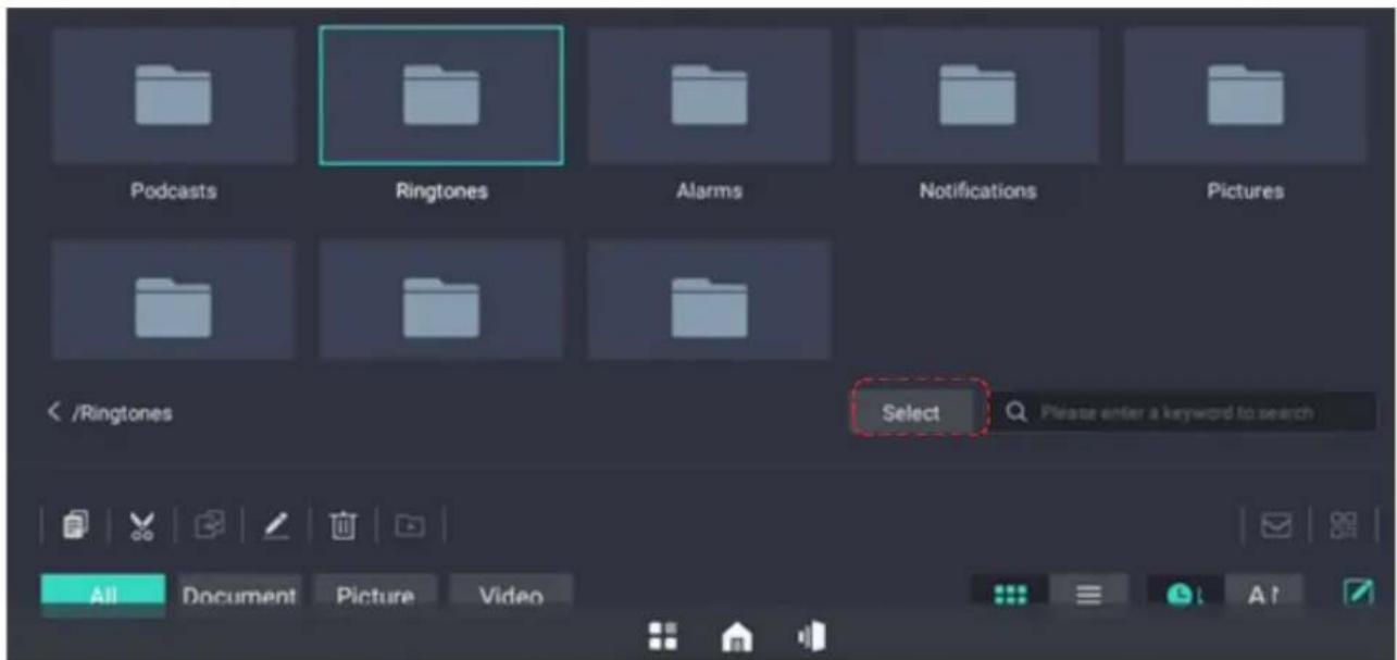
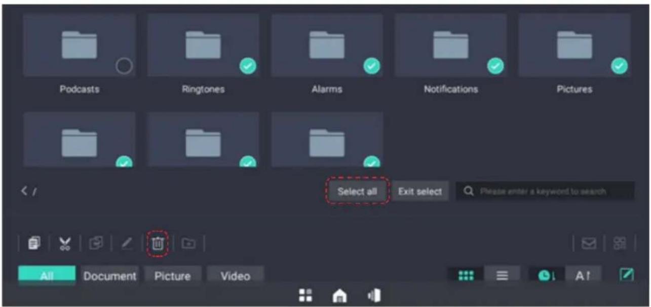
- Batch deletion of files: Click the select button to enter the batch selection state, select the files to be deleted in batch, then select the edit button, call up the operation bar, and select delete. If you are sure to delete the selected file, select OK.
Using the Vision Board
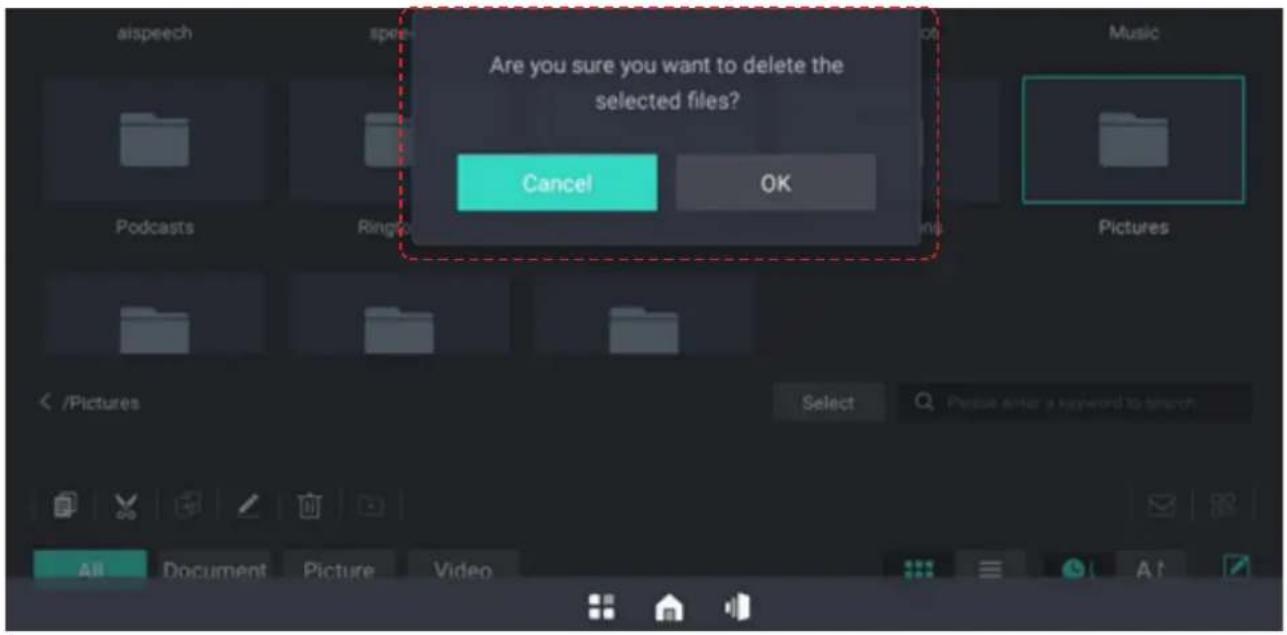
- The deletion operation needs the reconfirmation by the user. When the user performs the operation of deleting the folder, the folder and the files contained therein will be deleted at the same time.
6.7.5 Rename Files (Folders)
Users can modify file (folder) names.
(1) Select the file (folder) to be renamed, and change the file (folder) name.
(2) File (folder) renaming needs to comply with the file (folder) naming convention. The naming convention is as follows:
a. The file (folder) name cannot contain illegal characters (illegal characters include: / \ : * ? "<> | etc.)
b. The length of the file (folder) name can not exceed 255 characters. When the user exceeds 255 characters in the input process, it is not allowed to continue to input.
c. The user is allowed to enter a space at the first position of the file name. After the user enters a space to confirm the file name, the first consecutive space will be automatically filtered.
d. Users are not able to change the file type during renaming.
6.7.6 New Folders
Select New Folder, the new folder is successful, the name is New Folder (1), and then sort in order.
6.7.7 View File Properties
(1) Switch to the display mode of the list, you can often see the properties of the file (folder); or click a file (folder), edit and select some files (folder), you can preview the properties or number of the file (folder);
(2) View file attributes: the viewable contents include name, size, modification time, and the detailed rules are as follows:
i. When the file size is <1024kb, the display unit is KB;
ii. When 1024KB ≤ file size <1024mb, the display unit is MB;
iii. When1024MB≤ file size<1024GB, the display unit is GB;
c. Modification time: Display the time when the file/folder was last modified, and the display format is minute/hour/mm/dd/yyyy.
(3) When multiple files (folders) are selected, the quantity will be displayed. Other properties are not displayed.
Using the Vision Board
6.7.8 File Sharing
The ways to share files include QR code and email. Shared files are sent as attachments in email sharing.
6.7.9 File Search
Files are differentiated according to file types. Quick file lookup by file name is supported.
(1) File (folder) search is supported in the folder, and match according to search keywords.
(2) Full path searches for files (folders) is supported for all documents, pictures, and video categories.
6.8 App
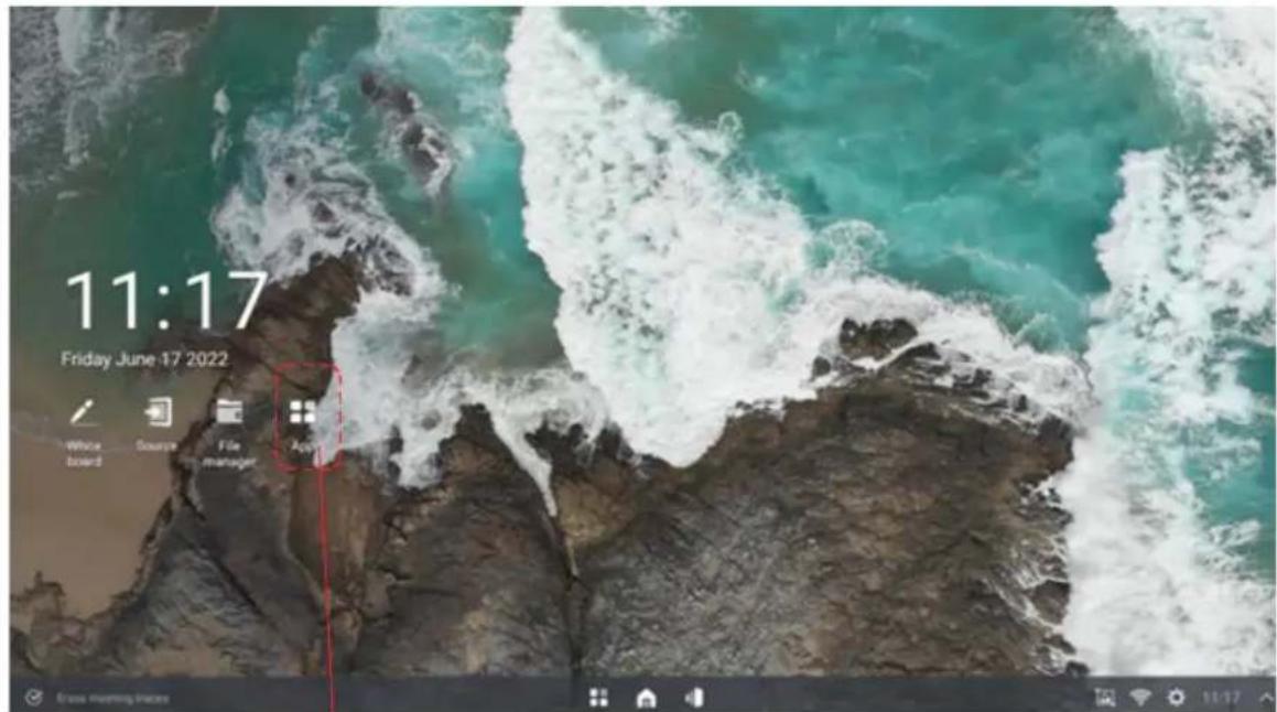
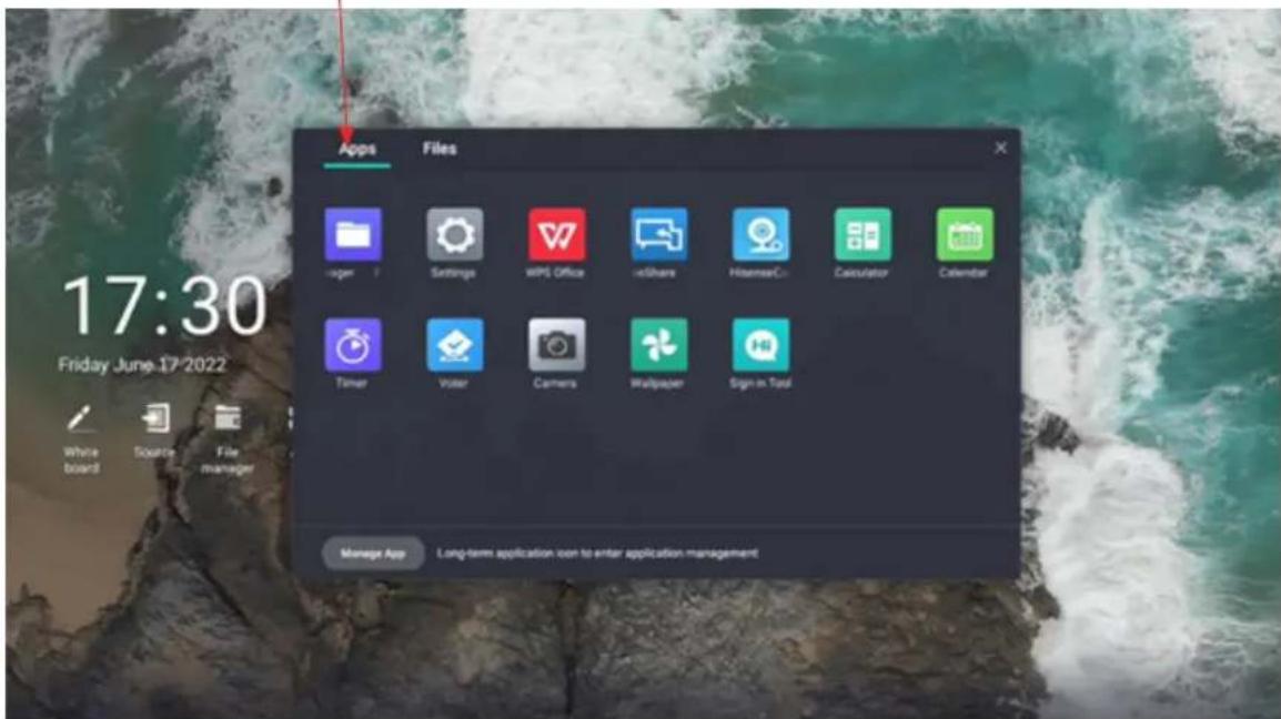
6.8.1 List of all Applications
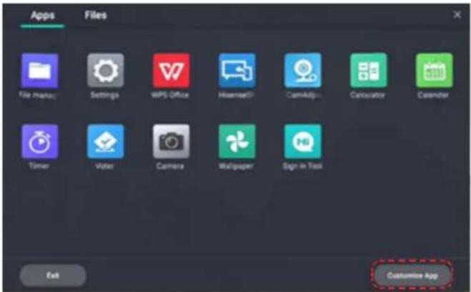
- Click the [APP] icon on the home page to open all applications.
6.8.2 Application Management
Click the [Manage App] icon to delete non-preset apps.
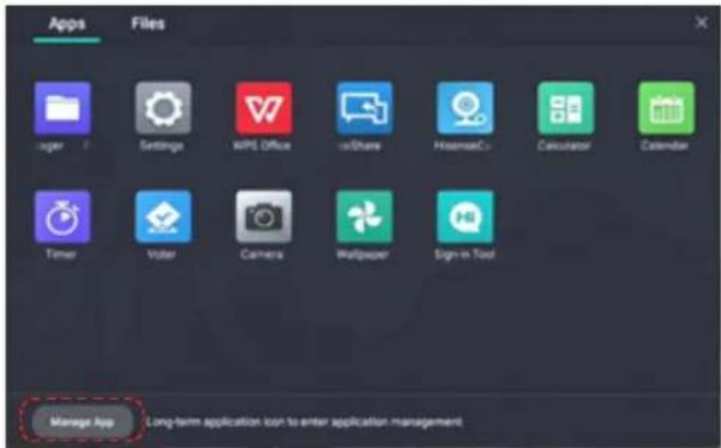
You can add apps to the homepage by clicking [Customize App].
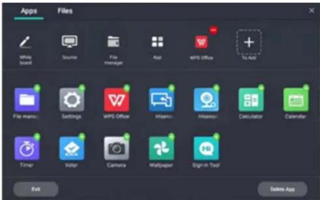
6.8.3 Add Apps to Home Page
Select the app with green plus icon to add it to the home page display.
Use [Delete Apps] to delete the apps preset on the homepage.
6 apps are supported at most on the home page.
6.9 Wireless Cast
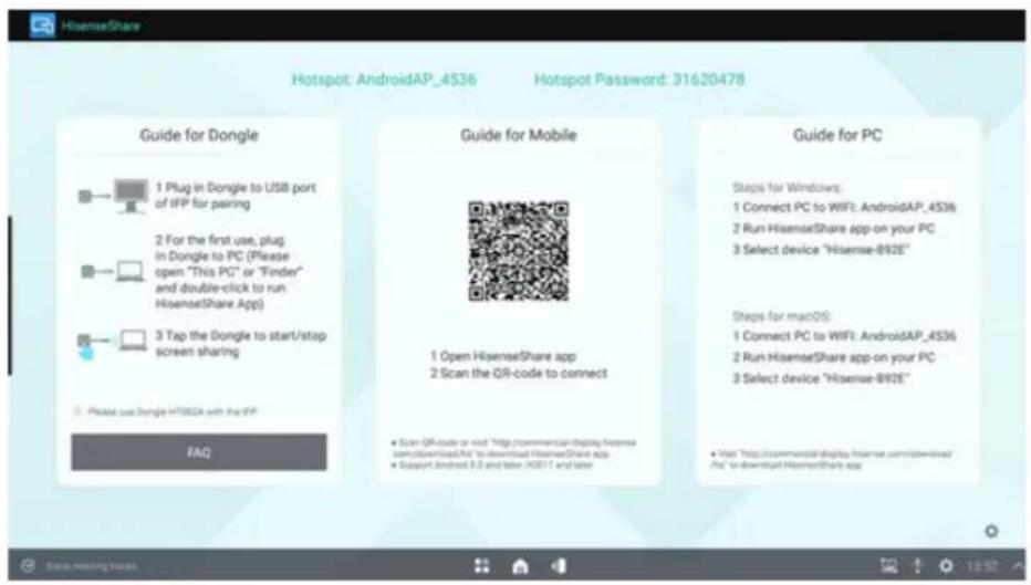
6.9.1 Guide for Dongle
(1) Pairing
Pairing method:
Insert the Wireless Cast into the USB port of the whole machine, and pair it. After successful, insert it into the USB port of computer, and automatically run Cast software. Click the Wireless Cast button according to the prompts.
Pairing and Miracast can be used with both Android and Windows, and there is no need to re-pair when switching to another system after pairing.
(2) Startup/termination of Miracast
Tap the Wireless Cast to start/terminate the the Cast.
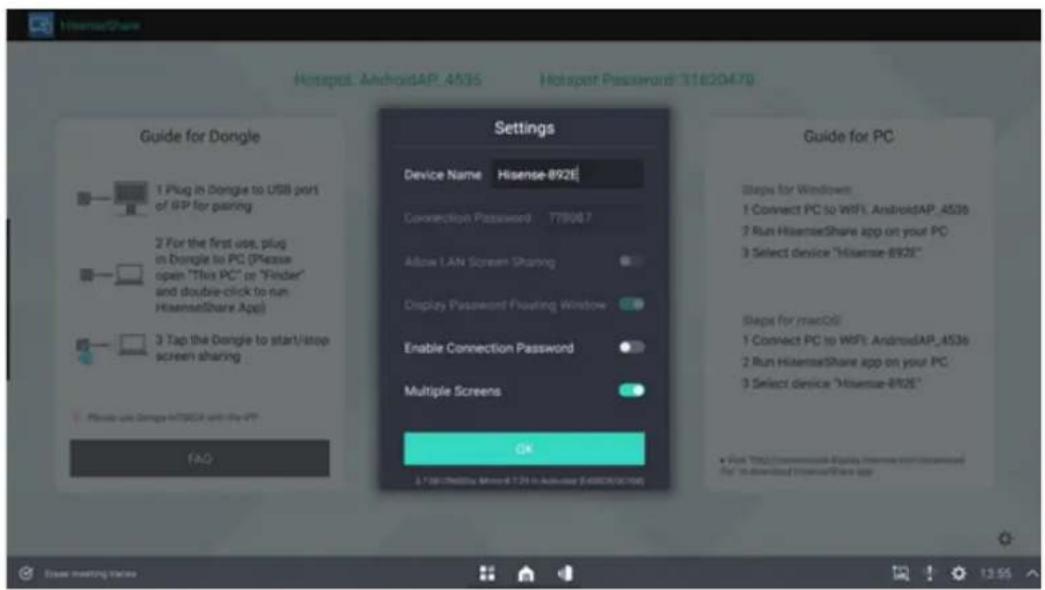
6.9.2 Guide for PC
Setting name, pairing password, LAN Miracast, whether to activate the connection code, screen group
6.9.3 Guide for Phone
1. Download mode:
Download from www.hisense-b2b.com or scan the QR code on the screen. Search the application of "HisenseShare" in Google App Store and Apple App Store.
2. Connect a mobile phone to the screen
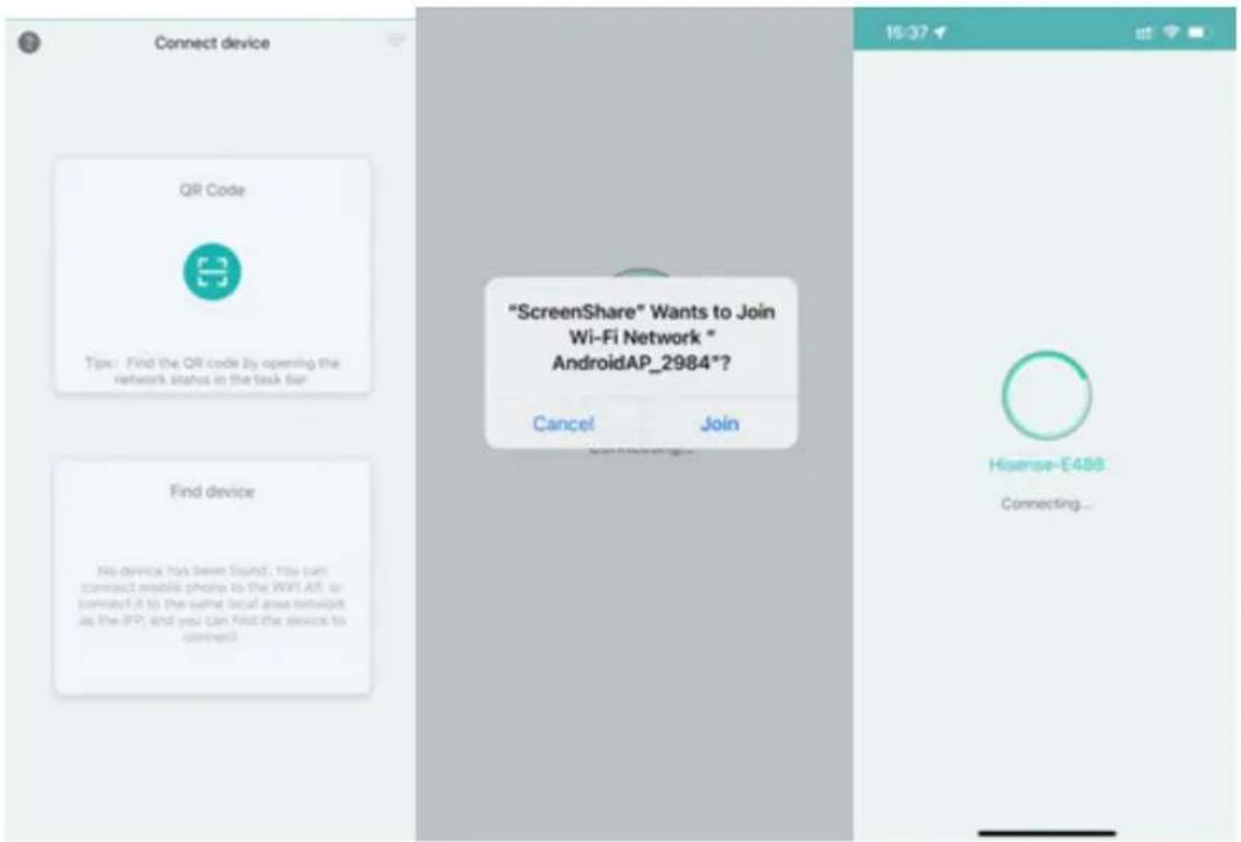
Open the HisenseShare APP and click QR Code. Scan the QR code on the screen to connect the mobile phone to the screen.
Using the Vision Board
- Click Mirroring to display the mobile phone contents on the screen; Click Anti Mirroring to display the screen contents on the mobile phone, and the mobile phone can be used as a touchpad to control the screen.
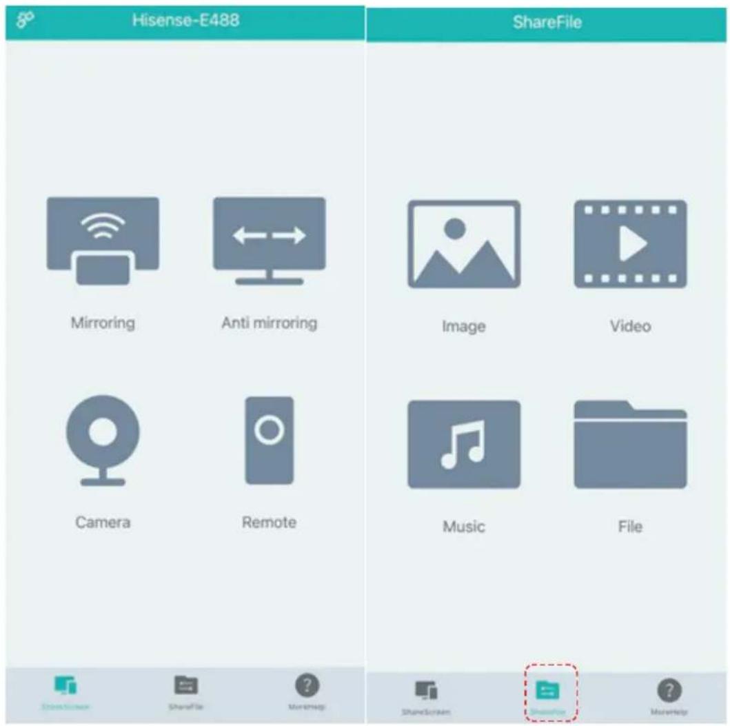
- Click ShareFile to display the images, videos, music and files saved in the mobile phone on the screen.
6.10 Split Screen Collaboration
6.10.1 Startup of Split Screen
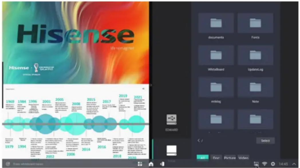
It is supported to open two apps simultaneously, side by side, and to adjust the screen proportion of the split screen.
- Open two or more apps that enable split screen
- If the user is already running the app in full screen, he/she may open all apps or task views on the global taskbar, and click to select another app and open it;
- When opening the second app, push the original full-screen application window to the left half-screen display, the second application is displayed on the right half-screen and the split-screen display ratio is 1:1;
- During the split screen display, it supports dragging the screen-dividing line in the middle of the screen, changing the proportion of split screen application window, and changing the application adaptive menu and content with the proportion of split screen;
- After the split screen, application windows on the left and right side support independent operations, such as clicking, scrolling, gesture operations, etc.;
- For the application windows on the left and right sides after the split screen, if one of the applications is minimized or closed, the split screen mode will be exited, and the remaining application will be displayed in full screen. If one application is maximized, the split-screen mode will be exited and the other application will be hidden to the background;
- Split screen supports file interaction between windows. When the split screen between file manager and whiteboard is supported, the picture file can be directly dragged to the whiteboard and inserted, and there are no functional requirements for the interaction between other split-screen windows.
- When the split screen is supported, the left and right windows are quickly switched, and the split screen ratio maintains the size of left and right windows;
- The specific proportion of small windows shall be determined according to the application menu and content to determine the minimum display of split screen window. When an application is dragged to 1/5th of the screen after the split screen transit, the window will be hidden automatically and the window on the other side will be displayed in full screen.
6.11 Apps Installation
- Copy the file to the USB disk;
- Insert the USB disk into the large-screen terminal, and open the folder of the USB in the file manager;
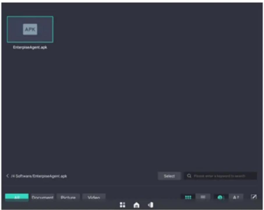
- Find the APK to be installed in the folder;
- Click APK or click Open to install;
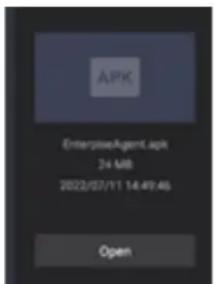
- After the installation is complete, the installed apps can be found in the applications menu;
6.12 Software Updates
6.12.1 Online Updates
- Whilst connected to the Internet, check the system version in [Settings] → [System Updates]. If it is already the latest version, there is no need to update it. If there is a new version, whether to update the new version will be prompted.
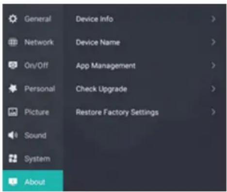
- Select the version to be updated and download the latest version;
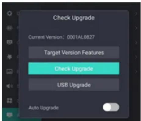
- After the download is complete, confirm to perform the upgrade. After confirmation, the system starts to refresh the version;
- After the version refresh is complete, the system automatically restarts.
6.12.2 Software Update vis USB
- Unzip the installation package and copy it to the root directory of the USB disk. The USB disk folder is named as: Target.
- Copy the version to the USB disk and directory;
- Insert the USB disk into the large-screen terminal;
- Restart the system, and the system prompts whether to update to a newer version.
- Select the update to enter the system update page;
- After the update is completed, the system will automatically restart;
6.13 IP Control
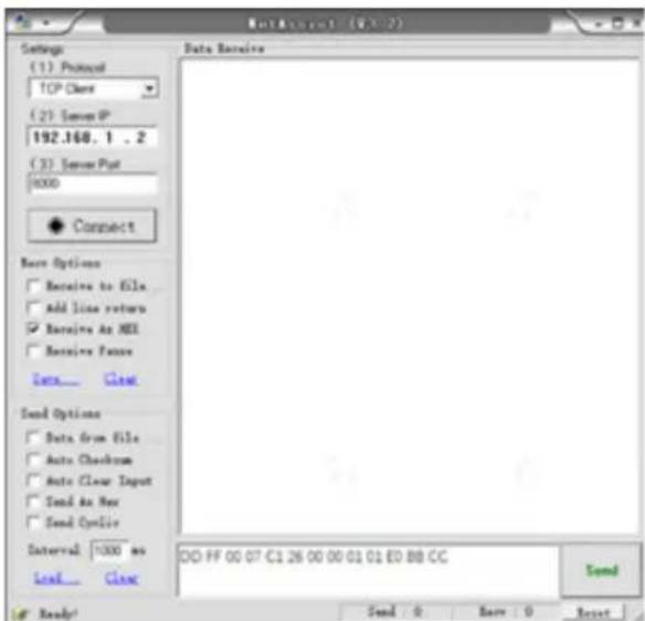
IP Control function is supported through Device Lan deployment. The Server and Client should be in the same LAN. The IP Control is a server. It Supports TCP\IP Network Protocol and Hex String Command format. The Software needs to input the port number and start. After the starting the software, the Client software connects to the IP Control software. The Client APP need to input Server IP and Server Port number.
- Start the "IP Control" software on the device
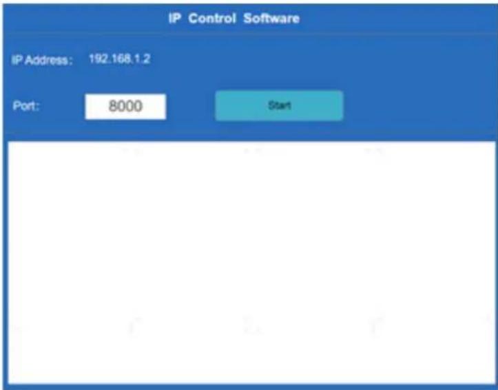
- IP Address(192.168.1.2) can't edit on the APP. It needs to edit on the set menu.
- Set port Number. The default port number is 8000. If the port 8000 is occupied, please change the port(0-12000)
- Click "Start" Button, it will show "Stop"; Click "Stop" Button, it will show "Start".
For Example: Mute Control Command-Mute ON
DD FF 00 07 C1 26 00 00 01 01 E0 BB CC
NOTE
- Verify is the exclusive OR of Length, Command code, ID and Data.
7. Serial Protocol
Serial port status
The device can receive the serial port command sent by the external controller or OPS of the device.
Refer to the following table for the specific command protocol:
-
Baud rate: 9600 → PC
-
Control section: PC → The device
-
Response section: Android
| Protocol header | Length | Command code ID | Data | Verify | Protocol tail | |||||||||
| Screen on/off | On PC to device | DD FF 00 | 07 C1 | 31 | 00 00 | 01 00 | F6 | BB CC | ||||||
| On Device to PC | AB AB 00 | 07 C1 | 31 | 00 00 | 01 00 | F6 | CD | CD | ||||||
| Off PC to device | DD FF 00 | 07 C1 | 31 | 00 00 | 01 01 | F7 | BB CC | |||||||
| Off Device to PC | AB AB 00 | 07 C1 | 31 | 00 00 | 01 01 | F7 | CD | CD | ||||||
| Current Signal Source Query | PC to device | DD FF 00 | 06 C1 | 1 | A 00 | 00 01 | DC BB CC | |||||||
| Device to PC | AB AB 00 | 09 C1 | 1 | A 00 | 00 01 | XX XXXX | XX CD | CD | ||||||
| Remark | Data: XX XX XX05 03 02: OPS05 03 00: Front HDMI05 03 01: Side HDMI05 03 03: Type-C05 03 04: DP | |||||||||||||
| Software Version Query | PC to device | DD FF 00 | 06 C1 | 1B | 00 00 | 01 | DD BB CC | |||||||
| Device to PC | AB AB 00 | 09 C1 | 1B | 00 00 | 01 | XX XXXX | XX CD | CD | ||||||
| Remark | The first XX is the Year.The second XX is the Month.The third XX is the Day. | |||||||||||||
| Set Time (Y/M/D) | PC to device | DD FF 00 | 09 C1 | 1C | 00 00 | 01 | XX XXXX | XX | BB CC | |||||
| Device to PC | AB AB 00 | 09 C1 | 1C | 00 00 | 01 | XX XXXX | XX CD | CD | ||||||
| Remark | The first XX is the Year.The second XX is the Month.The third XX is the Day.If set failures, these three XX return FF. | |||||||||||||
Serial Protocol
| Protocol header | Length C | Command code ID D | Data Verify | Protocol tail | ||||||||||
| Set Time (H/M/S) | PC to device | DD | FF 00 | 09 C | 1 1D | 00 00 | 01 | XX XXXX | XX BB CC | |||||
| Device to PC | AB | AB 00 | 09 C | 1 1D | 00 00 | 01 | XX XXXX | XX CD CD | ||||||
| Remark | The first XX is the Hour.The second XX is the Minute.The third XX is the Second.If set failures, these three XX return FF. | |||||||||||||
| Reboot Screen | PC to device | DD | FF 00 | 06 C | 1 1E | 00 00 | 01 D | 8 BB | CC | |||||
| Device to PC | AB | AB 00 | 06 C | 1 1E | 00 00 | 01 D | 8 CD | CD | ||||||
| Signal Source Selection | PC to device | DD | FF 00 | 07 C | 1 08 | 00 00 | 01 XX | XX BB CC | ||||||
| Device to PC | AB | AB 00 | 07 C | 1 08 | 00 00 | 01 XX | XX CD CD | |||||||
| Remark | Data: XX04: OPS05: Front HDMI06: Side HDMI0B: Type-C0C: DP | |||||||||||||
| Screen on/off Query | PC to device | DD | FF 00 | 06 C | 1 32 | 00 00 | 01 | F4 BB CC | ||||||
| Device to PC | AB | AB 00 | 07 C | 1 32 | 00 00 | 01 XX | XX CD CD | |||||||
| Remark | Data: XX00 is the screen off state.01 is the screen on state. | |||||||||||||
Serial Protocol
| Protocol header | ID Length Command code Protocol tail | ||||||||||
| Switch on/off | On PC to device | DD FF 01 04 | A1 00 00 00 BB CC | ||||||||
| On Device to PC | AB AB 01 04 | A1 00 00 00 CD CD | |||||||||
| Off PC to device | DD FF 01 04 | A1 01 00 00 BB CC | |||||||||
| Off Device to PC | AB AB 01 04 | A1 01 00 00 CD CD | |||||||||
| Volume Control | PC to device | DD FF 01 04 | A1 07 00 XX BB CC | ||||||||
| Device to PC | AB AB 01 04 | A1 07 00 XX CD CD | |||||||||
| Remark XX is the volume value. | |||||||||||
| Brightness Control | PC to device | DD FF 01 04 | A1 08 00 XX BB CC | ||||||||
| Device to PC | AB AB 01 04 | A1 08 00 XX CD CD | |||||||||
| Remark XX is the brightness value. | |||||||||||

NOTE
- Verify is the exclusive OR of Length, Command code, ID and Data.
- All data are hexadecimal values.
- For all commands received by the device, the protocol header needs to be changed to AB AB and the protocol tail needs to be changed to CD CD when returning to the PC.
- Precautions for control terminal programming: For the power-on command, AB AB 01 04 A1 00 00 00 CD CD are returned after the power-on action is executed; if the command is not received, the power-on command needs to be sent again. After Android is turned on, the PC will receive AB AB 01 04 A1 00 00 00 CD CD again, and then the PC can send a control command to the device. If the correct command is not returned after any command is sent, the command should be sent again at least after 500ms.
- In Android standby state, the device only supports startup commands.
8. Appendix
8.1 Specification
Features, appearance and specifications are subject to change without notice.
| Product name Hisense Interactive Digital Board | ||
| Model 65WR6BE | ||
| Size(mm) (W×H×D) excluding base 1497 × 915 × 100 | ||
| Weight(kg) excluding base 36.9 | ||
| Visual picture diagonal size (cm) 164 | ||
| Power supply 100-240V 50/60Hz 2.7A ~ | ||
| Wireless LAN Module specifications | Model ZDGFMT7612U WF-M668-UWP1 | |
| Frequency Range | 2.4~2.4835GHz5.15~5.85GHz | |
| Output Power (Max.) | 2.4~2.4835GHz 16dBm5.15~5.85GHz 14dBm | |
| Display resolution 3840 × 2160 | ||
| Sound power 15W + 15W | ||
| Executive standard Q/0202RSR 620 | ||
| Environmental conditions | Operating temperature 5°C ~ 35°COperating humidity 20% ~ 80%RHAtmospheric pressure 86kPa ~ 106kPa | |
| Product name Hisense Interactive Digital Board | ||
| Model 75WR6BE | ||
| Size(mm) (W×H×D) excluding base 1718 × 1040 × 102 | ||
| Weight(kg) excluding base 47.5 | ||
| Visual picture diagonal size (cm) 189 | ||
| Power supply 100-240V 50/60Hz 3.5A ~ | ||
| Wireless LAN Module specifications | Model ZDGFMT7612U WF-M668-UWP1 | |
| Frequency Range | 2.4~2.4835GHz5.15~5.85GHz | |
| Output Power (Max.) | 2.4~2.4835GHz 16dBm5.15~5.85GHz 14dBm | |
| Display resolution 3840 × 2160 | ||
| Sound power 15W + 15W | ||
| Executive standard Q/0202RSR 620 | ||
| Environmental conditions | Operating temperature 5°C ~ 35°COperating humidity 20% ~ 80%RHAtmospheric pressure 86kPa ~ 106kPa | |
Appendix
| Product name Hisense Interactive Digital Board | |||
| Model 86WR6BE | |||
| Size(mm) (W×H×D) excluding base 1957 × 1178 × 94 | |||
| Weight(kg) excluding base | 62 | ||
| Visual picture diagonal size (cm) | 217 | ||
| Power supply | 100-240V ~50/60Hz 4.6A | ||
| Wireless LAN Module specifications | Model | ZDGFMT7612U | WF-M668-UWP1 |
| Frequency Range | 2.4~2.4835GHz5.15~5.85GHz | ||
| Output Power (Max.) | 2.4~2.4835GHz 16dBm5.15~5.85GHz 14dBm | ||
| Display resolution | 3840 × 2160 | ||
| Sound power | 15W + 15W | ||
| Executive standard | Q/0202RSR 620 | ||
| Environmental conditions | Operating temperature 5°C ~ 35°COperating humidity 20% ~ 80%RHAtmospheric pressure 86kPa ~ 106kPa | ||
The supported video formats are as follows:
| Encapsulation | Video decoding | Audio decoding | |||
| Type Resolution(Max) | Bit rate(Max) | Frame rate(Max) | |||
| .avi Xvid 1 | 920 × 1080 | 50Mbps 30fps | Dolby Audio, MPEG1(Layer1,2,3) | ||
| .avi .mpg .ts | MPEG2 1920 | × 1080 80Mbps | 30fps | Dolby Audio, MPEG1(Layer1,2,3) | |
| .ts .mkv .avi .mp4 .flv | H.264 3840 | × 2160 160Mbps | 30fps | Dolby Audio, AAC, MPEG1(Layer1,2,3) | |
| .avi .mpg .mov | MPEG4 1920 | × 1080 50Mbps | 30fps | Dolby Audio, MPEG1(Layer1,2,3) | |
| .mkv .mp4 .ts | H.264 3840 | × 2160 160Mbps | 30fps | Dolby Audio, AAC, MPEG1(Layer1,2,3) | |
| .ts .mkv .mp4 | H.265 3840 | × 2160 160Mbps | 60fps | Dolby Audio, AAC, MPEG1(Layer1,2,3) | |
Dolby Audio: Support Dolby Digital, Dolby Digital Plus, Dolby AC4, and Dolby TrueHD.
NOTE
Formats listed above may not all supported by the device as video making tools are not unified.
Appendix
| Signal formats supported by HDMI port | |
| RGB/60Hz 640 × 480, | 800 × 600, 1024 × 768 |
| YUV/50Hz 576i, 576p, | 720p, 1080i, 1080p |
| YUV/60Hz 480i, 480p, | 720p, 1080i, 1080p |
| YUV/24Hz 25Hz 30Hz 3840 | × 2160, 4096 × 2160 |
| YUV420/50Hz 60Hz 3840 x | 2160, 4096 × 2160 |
| YUV444/50Hz 60Hz 3840 x | 2160, 4096 × 2160 |
| RGB444/50Hz 60Hz 3840 x | 2160, 4096 × 2160 |
NOTE
HDMI standard and HDMI enhance are supported by the device. HDMI standard is the default, which only supports part of formats listed above. HDMI enhance supports all formats listed above. If HDMI enhance is needed, you can tab menu under HDMI Version and select HDMI enhance.
| Signal formats supported by DP port | |
| RGB/60Hz 640 × 480, | 800 × 600, 1024 × 768 |
| YUV/50Hz 576p, 720p, | 1080i, 1080p |
| YUV/60Hz 480p, 720p, | 1080i, 1080p |
| YUV/24Hz 25Hz 30Hz 3840 | x 2160, 4096 x 2160 |
| YUV444/50Hz 60Hz 3840 x | 2160, 4096 × 2160 |
| RGB444/50Hz 60Hz 3840 x | 2160, 4096 × 2160 |
8.2 Other Infomation
Recycling/Licenses
WEEE (Waste Electronic Electric Equipment)
European Directive 2012/19/EU
This symbol on the product or on its packaging indicates that this product must not be disposed of with your household waste. Instead, it is your responsibility to dispose of your waste equipment by handing it over to a designated collection point for the recycling of waste electrical and electronic equipment. The separate collection and recycling of your waste equipment at the time of disposal will help to conserve natural resources and ensure that it is recycled in a manner that protects human health and the environment. For more information about where you can drop off your waste equipment for recycling, please contact your local city office, your household waste disposal service or the shop where you purchased the product.
Batteries
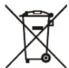
In accordance with the Battery Directive, used batteries should not be disposed of in the domestic waste. Dispose your batteries in the collection containers specific for this purpose in retail stores.
ROHS (Restriction of Hazardous Substance) European Directive 2011/65/EU

This European directive limits the use of dangerous and hazardous substances which are difficult to recycle.
This allows recycling easily the EEE and contributes to the safeguard of the environment.
Substances included in this product match to the RoHS directive.

HIGH-DEFINITION MULTIMEDIA INTERFACE
The terms HDMI and HDMI High-Definition Multimedia Interface, and the HDMI Logo are trademarks or registered trademarks of HDMI Licensing Administrator, Inc. in the United States and other countries.
8.3 Certification and Compliance
FCC Notice
This device has been tested and found to comply with the limits for a Class B digital device pursuant to Part 15 of the FCC Rules. These limits are designed to provide reasonable protection against harmful interference in a residential installation. This device generates, uses, and can radiate radio frequency energy and, if not installed and used in accordance with the instructions, may cause harmful interference to radio communications.
However, there is no guarantee that interference will not occur in a particular installation. If this device does cause harmful interference to radio or television reception, which can be determined by turning the device off and on, the user is encouraged to try to correct the interference by one or more of the following measures:
- Reorient or relocate the receiving antenna.
- Increase the separation between the device and receiver.
- Connect the device into an outlet on a circuit different from that to which the receiver is connected.
- Consult the dealer or an experienced radio/Screen technician for help.
NOTE: The manufacturer is not responsible for any radio or Screen interference caused by unauthorized modifications to this equipment. Such modifications could void the user's authority to operate the equipment.
The Wi-Fi Module complies with FCC radiation exposure limits set forth for an uncontrolled environment. This device should be installed and operated with a minimum distance of 20 centimeters between the radiator and your body.
This device complies with Industry Canada's license-exempt RSSs. Operation is subject to the following two conditions:
(1) This device may not cause interference; and
(2) This device must accept any interference, including interference that may cause undesired operation of the device.
Declaration of Conformity
Trade Name: Hisense
Model: 65WR6BE / 75WR6BE / 86WR6BE
Responsible Party: Hisense USA Corporation
Address: 7310 McGinnis Ferry Road, Suwanee, GA 30024
Telephone Number: 678-318-9060
This device complies with Part 15 of the FCC Rules. Operation is subject to the following two conditions: (1) this device may not cause harmful interference, and (2) this device must accept any interference received, including interference that may cause undesired operation.
8.4 EU Declaration of Conformity (DOC)
EU Declaration of conformity (DoC)
Unique identification of this DoC: hisense-03
We, Declare under our sole responsibility that the product:
Product Name: Hisense Interactive Digital Board
Trade Name: Hisense
Model: 65WR6BE
To which this declaration relates is in conformity with the essential requirements and other relevant requirements of the radio equipment directive(2014/53/EU), Ecodesign Directive(2009/125/EC)& Regulation (EU) 2019/2021, ROHS Directive (2011/65/EU). The product is in conformity with the following standards and/or other normative documents:
Health & Safety (Art. 3(1)(a)): EN IEC62311:2020
EN62368-1:2014+A11:2017
EMC (Art. 3(1)(b)): EN55032:2015+A11:2020
EN55035:2017+A11:2020
EN IEC 61000-3-2:2019
EN61000-3-3:2013+A1:2019
EN301489-1 V2.2.3:2019
EN301489-17 V3.2.4:2020
Spectrum (Art. 3(2)): EN300328 V2.2.2:2019
EN301893 V2.1.1:2017
ErP: Transitional Test Method for Ecodesign and Energy Labelling requirements for electronic displays
RoHS: IEC 63000:2018
Software * 65. V0000.WR6.BE.00.01A.L0625
*The company reserves the right to install updated Software versions to improve the performance of the appliance.
Place and date of issue (of this DoC): QingDao 2021/08/20
Signed by or for the manufacturer: Hisense Commercial Display Co., Ltd.
Address: No.218, Qianwangang Road, Economy& Technology Development Zone, Qingdao, China
Title: Product manager
Name (in print): Yanglin
YangLin
EU Declaration of conformity (DoC)
Unique identification of this DoC: hisense-03
We, Declare under our sole responsibility that the product:
Product Name: Hisense Interactive Digital Board
Trade Name: Hisense
Model: 75WR6BE
To which this declaration relates is in conformity with the essential requirements and other relevant requirements of the radio equipment directive(2014/53/EU), Ecodesign Directive(2009/125/EC)& Regulation (EU) 2019/2021, ROHS Directive (2011/65/EU). The product is in conformity with the following standards and/or other normative documents:
Health & Safety (Art. 3(1)(a)): EN IEC62311:2020
EN62368-1:2014+A11:2017
EMC (Art. 3(1)(b)): EN55032:2015+A11:2020
EN55035:2017+A11:2020
EN IEC 61000-3-2:2019
EN61000-3-3:2013+A1:2019
EN301489-1 V2.2.3:2019
EN301489-17 V3.2.4:2020
Spectrum (Art. 3(2)): EN300328 V2.2.2:2019
EN301893 V2.1.1:2017
ErP: Transitional Test Method for Ecodesign and Energy Labelling requirements for electronic displays
RoHS: IEC 63000:2018
Software * 75. V0000.WR6.BE.00.01A.L0625
*The company reserves the right to install updated Software versions to improve the performance of the appliance.
Place and date of issue (of this DoC): QingDao 2021/08/20
Signed by or for the manufacturer: Hisense Commercial Display Co., Ltd.
Address: No.218, Qianwangang Road, Economy& Technology Development Zone, Qingdao, China
Title: Product manager
Name (in print): Yanglin
YangLin
EU Declaration of conformity (DoC)
Unique identification of this DoC: hisense-03
We, Declare under our sole responsibility that the product:
Product Name: Hisense Interactive Digital Board
Trade Name: Hisense
Model: 86WR6BE
To which this declaration relates is in conformity with the essential requirements and other relevant requirements of the radio equipment directive(2014/53/EU), Ecodesign Directive(2009/125/EC)& Regulation (EU) 2019/2021, ROHS Directive (2011/65/EU). The product is in conformity with the following standards and/or other normative documents:
Health & Safety (Art. 3(1)(a)): EN IEC62311:2020
EN62368-1:2014+A11:2017
EMC (Art. 3(1)(b)): EN55032:2015+A11:2020
EN55035:2017+A11:2020
EN IEC 61000-3-2:2019
EN61000-3-3:2013+A1:2019
EN301489-1 V2.2.3:2019
EN301489-17 V3.2.4:2020
Spectrum (Art. 3(2)): EN300328 V2.2.2:2019
EN301893 V2.1.1:2017
ErP: Transitional Test Method for Ecodesign and Energy Labelling requirements for electronic displays
RoHS: IEC 63000:2018
Software * 86. V0000.WR6.BE.00.01A.L0625
*The company reserves the right to install updated Software versions to improve the performance of the appliance.
Place and date of issue (of this DoC): QingDao 2021/08/20
Signed by or for the manufacturer: Hisense Commercial Display Co., Ltd.
Address: No.218, Qianwangang Road, Economy& Technology Development Zone, Qingdao, China
Title: Product manager
Name (in print): Yanglin
YangLin
UK Declaration of conformity (DoC)
Unique identification of this DoC: ZGB-DOC-20210820-001
We, Declare under our sole responsibility that the product:
Product Name: Hisense Interactive Digital Board
Trade Name: Hisense
Model: 65WR6BE
To which this declaration relates is in conformity with the essential requirements and other relevant requirements of the Radio Equipment Regulations 2017, The Ecodesign for Energy-related Products Regulations 2010, Ecodesign for Energy-related Products and Energy Information Regulations 2021 (with respect to Ecodesign Requirements for Electronic Displays)& The Restriction of the Use of Certain Hazardous Substances in Electrical and Electronic Equipment Regulations 2012. The product is in conformity with the following standards and /or other normative documents:
Health & Safety (Art. 3(1)(a)): EN IEC62311:2020
EN62368-1:2014+A11:2017
EMC (Art. 3(1)(b)): EN55032:2015+A11:2020
EN55035:2017+A11:2020
EN IEC 61000-3-2:2019
EN61000-3-3:2013+A1:2019
EN301489-1 V2.2.3:2019
EN301489-17 V3.2.4:2020
Spectrum (Art. 3(2)): EN300328 V2.2.2:2019
EN301893 V2.1.1:2017
ErP: Transitional Test Method for Ecodesign and Energy Labelling requirements for electronic displays
RoHS: IEC 63000:2018
Software * 65. V0000.WR6.BE.00.01A.L0625
*The company reserves the right to install updated Software versions to improve the performance of the appliance.
Place and date of issue (of this DoC): QingDao 2021/08/20
Signed by or for the manufacturer: Hisense Commercial Display Co., Ltd.
Address: No.218, Qianwangang Road, Economy& Technology Development Zone, Qingdao, China
Title: Product manager
Name (in print): Yanglin
YangLin
UK Local Representative
Alltrade Ltd.
Sussex House Business Park,274 Old Shoreham Road,
BRIGHTON & HOVE, BN3 7EU
UK Declaration of conformity (DoC)
Unique identification of this DoC: ZGB-DOC-20210820-001
We, Declare under our sole responsibility that the product:
Product Name: Hisense Interactive Digital Board
Trade Name: Hisense
Model: 75WR6BE
To which this declaration relates is in conformity with the essential requirements and other relevant requirements of the Radio Equipment Regulations 2017, The Ecodesign for Energy-related Products Regulations 2010, Ecodesign for Energy-related Products and Energy Information Regulations 2021 (with respect to Ecodesign Requirements for Electronic Displays)& The Restriction of the Use of Certain Hazardous Substances in Electrical and Electronic Equipment Regulations 2012. The product is in conformity with the following standards and /or other normative documents:
Health & Safety (Art. 3(1)(a)): EN IEC62311:2020
EN62368-1:2014+A11:2017
EMC (Art. 3(1)(b)): EN55032:2015+A11:2020
EN55035:2017+A11:2020
EN IEC 61000-3-2:2019
EN61000-3-3:2013+A1:2019
EN301489-1 V2.2.3:2019
EN301489-17 V3.2.4:2020
Spectrum (Art. 3(2)): EN300328 V2.2.2:2019
EN301893 V2.1.1:2017
ErP: Transitional Test Method for Ecodesign and Energy Labelling requirements for electronic displays
RoHS: IEC 63000:2018
Software * 75. V0000.WR6.BE.00.01A.L0625
*The company reserves the right to install updated Software versions to improve the performance of the appliance.
Place and date of issue (of this DoC): QingDao 2021/08/20
Signed by or for the manufacturer: Hisense Commercial Display Co., Ltd.
Address: No.218, Qianwangang Road, Economy& Technology Development Zone, Qingdao, China
Title: Product manager
Name (in print): Yanglin
YangLin
UK Local Representative
Alltrade Ltd.
Sussex House Business Park,274 Old Shoreham Road,
BRIGHTON & HOVE, BN3 7EU
UK Declaration of conformity (DoC)
Unique identification of this DoC: ZGB-DOC-20210820-001
We, Declare under our sole responsibility that the product:
Product Name: Hisense Interactive Digital Board
Trade Name: Hisense
Model: 86WR6BE
To which this declaration relates is in conformity with the essential requirements and other relevant requirements of the Radio Equipment Regulations 2017, The Ecodesign for Energy-related Products Regulations 2010, Ecodesign for Energy-related Products and Energy Information Regulations 2021 (with respect to Ecodesign Requirements for Electronic Displays)& The Restriction of the Use of Certain Hazardous Substances in Electrical and Electronic Equipment Regulations 2012. The product is in conformity with the following standards and /or other normative documents:
Health & Safety (Art. 3(1)(a)): EN IEC62311:2020
EN62368-1:2014+A11:2017
EMC (Art. 3(1)(b)): EN55032:2015+A11:2020
EN55035:2017+A11:2020
EN IEC 61000-3-2:2019
EN61000-3-3:2013+A1:2019
EN301489-1 V2.2.3:2019
EN301489-17 V3.2.4:2020
Spectrum (Art. 3(2)): EN300328 V2.2.2:2019
EN301893 V2.1.1:2017
ErP: Transitional Test Method for Ecodesign and Energy Labelling requirements for electronic displays
RoHS: IEC 63000:2018
Software * 86. V0000.WR6.BE.00.01A.L0625
*The company reserves the right to install updated Software versions to improve the performance of the appliance.
Place and date of issue (of this DoC): QingDao 2021/08/20
Signed by or for the manufacturer: Hisense Commercial Display Co., Ltd.
Address: No.218, Qianwangang Road, Economy& Technology Development Zone, Qingdao, China
Title: Product manager
Name (in print): Yanglin
UK Local Representative
Alltrade Ltd.
Sussex House Business Park,274 Old Shoreham Road,
BRIGHTON & HOVE, BN3 7EU
Troubleshooting
9. Troubleshooting
Before preparing for repair, check the table below to see if you can find the cause of the problem.
If these steps do not resolve the problem, please contact the local service department.
| Problem Solution | |
| No sound or picture | Check if the power cord is connected to the wall outlet, and if the wall outlet has electricity.Check if you have pressed the Power button or Standby button.Check the volume. |
| Sound and picture are disturbed | Check whether this is caused by local electronic or magnetic devices and move these further away.Try plugging the LCD monitor's power plug into another outlet. |
| The screen cannot be powered on or the power indicator light is off. | Check whether the power supply is connected.Check whether the power supply plug is properly connected.Check whether the power outlet has electricity.Check whether the AC switch is enabled.Press the reset switch and start the system again. |
| The unit turns off unexpectedly. | Check whether standby mode is enabled.Check if there is a power outage in your area.Turn on the display and see if the problem is with the signal and control system. |
| Remote Control is not working. | Check whether something is obstructing the display's remote control receiver.Check whether the batteries in the remote control are installed correctly.Check whether the batteries need to be replaced. |
| There is no sound when the HDMI in channel is used. | Remove and insert the HDMI cable again. |
| The internal PC has no signal. | Check whether the internal PC is properly inserted in the slot.Check whether the internal PC is in shut down mode.Press the power button on the internal PC, and manually start up the internal PC. |
- Contents
- Safety Precautions
- Declaration
- Statement
- ATTENTION
- Disposal of Used Electrical & Electronic Equipment
- Important Notice
- Safeguards
- Safety Precautions
- Servicing
- Damage Requiring Service
- Replacement Parts
- Safety Check
- Heat
- Fire
- Off-gassing
- Introduction
- Package Contents
- NOTE
- Products View
- Front Panel | Control Panel
- Rear Panel | I/O Panel
- Introduction
- Remote Control
- Battery replacement method
- Precautions
- Effective range
- Installation Guide
- Precautions for Installation
- Wall Mount Kit Specifications (VESA)
- Installing the OPS (Optional)
- Installation Sequence
- Installing the Camera (optional)
- Installing the Camera
- Installation Guide
- Making Connections
- Making Connections
- NOTES
- Connecting to external audio device
- Connecting to a DP interface device
- Connecting to an HDMI input
- Connecting to an HDMI output
- Connecting to a Touch interface device
- Using an external interface with the touch screen and selection of the touch unit
- HEADPHONE Connect headphones for audio out of the screen.
- Connecting to a USB interface device
- Connecting to a network
- - Ethernet: auto
- Connecting to the OPS interface device
- - Switching on/off the OPS
- Getting Started
- Power On/Off
- Note:
- Using the Vision Board
- Initial Launch Setup
- Using the Vision Board
- Homepage and Taskbar
- - Homepage
- - Taskbar
- Using Gestures
- Five-finger Menu
- Settings
- How to enter settings?
- White Board
- Open the White Board
- Main Interface
- Handwriting
- Highlighter Color Selection
- Erase Options
- Insert Files
- - Insert pictures
- - Insert graphics
- Insert normal graphics
- Insert smart graphics
- - Insert tables
- Gesture Description
- More Features
- - Whiteboard Sharing
- QR code
- - Whiteboard Settings
- Page Tool
- Side-pull Whiteboard
- Source
- File Manager
- Document Management
- File View
- File (folder) Copy
- Delete Files (Folders)
- Rename Files (Folders)
- New Folders
- View File Properties
- File Sharing
- File Search
- App
- List of all Applications
- Application Management
- Add Apps to Home Page
- Wireless Cast
- Guide for Dongle
- Pairing
- Pairing method:
- Startup/termination of Miracast
- Guide for PC
- Guide for Phone
- Download mode:
- Connect a mobile phone to the screen
- Split Screen Collaboration
- Startup of Split Screen
- Apps Installation
- Software Updates
- Online Updates
- Software Update vis USB
- IP Control
- Serial Protocol
- Serial port status
- Serial Protocol
- Appendix
- Specification
- Appendix
- Other Infomation
- Batteries
- ROHS (Restriction of Hazardous Substance) European Directive 2011/65/EU
- Certification and Compliance
- FCC Notice
- Declaration of Conformity
- EU Declaration of Conformity (DOC)
- EU Declaration of conformity (DoC)
- UK Declaration of conformity (DoC)
- Troubleshooting
- Troubleshooting
Brand : HISENSE
Model : 65WR6BE
Category : Tableau blanc et accessoires