
Mach MS 3 - Audio Controller MARTIN - Free user manual and instructions
Find the device manual for free Mach MS 3 MARTIN in PDF.


| Product Type | Loudspeaker Controller |
| Brand | Martin |
| Model | Mach MS 3 |
| Input Type | Differential (electronically balanced) |
| Input Impedance | 47 kOhm |
| Maximum Input Level | +21 dBV (10.5 V) |
| Output Impedance | 50 Ohm |
| Maximum Output Level | +20 dBV |
| Frequency Response | 35 Hz – 120 kHz (3-way) |
| Total Harmonic Distortion (THD) | 0.0015% |
| Signal-to-Noise Ratio (S/N) | 112 dB |
| Controls | Output level per band (-∞ to +6 dB), Limiter DIP switches, Voltage selector |
| Indicators | 6 green LEDs (signal), 6 red LEDs (limiter), 1 blue LED (power) |
| Power Supply | 100-120 V / 220-240 V AC, 50/60 Hz (switchable) |
| Power Consumption | 9 W |
| Fuse Rating | 100 mA |
| Dimensions (H x W x D) | 1.75 x 19 x 5 in (44 x 482 x 128 mm) |
| Net Weight | 2.2 kg |
| Shipping Weight | 3.0 kg |
| Mounting | 19-inch rack, 1U height |
| Connectors | XLR (pin 1 shield, pin 2 +, pin 3 -); IEC mains |
| Protection Features | Subsonic filter (24 dB/oct Butterworth), limiter per band, sense feedback |
| Included Accessories | Speaker sense cable set, mains cable |
Frequently Asked Questions - Mach MS 3 MARTIN
User questions about Mach MS 3 MARTIN
0 question about this device. Answer the ones you know or ask your own.
Ask a new question about this device
Download the instructions for your Audio Controller in PDF format for free! Find your manual Mach MS 3 - MARTIN and take your electronic device back in hand. On this page are published all the documents necessary for the use of your device. Mach MS 3 by MARTIN.
USER MANUAL Mach MS 3 MARTIN
- Read this manual before operating the controller.
- To avoid the risk of electrical shock, do not remove any cover from the controller while it is connected to AC power.
- Do not expose the controller to rain or moisture.
General precautions
- Do not operate the controller near heat sources such as radiators, etcetera.
- Connect only to a power supply as marked on the controller.
- Do not drop the controller.
- Do not spill liquids onto or into the controller.
- Refer all service to a qualified technician.
Technical Background
When working with loudspeakers, there are 5 decisive factors for maximizing sound quality speaker lifetime:
- excursion control
- input power control
• frequency segmentation
• controller-generated distortion
• controller-generated noise
To avoid mechanical damage to the speaker units, the excursion of the speaker cones must be controlled. The M20.02, M20.03, and MS 3 accomplish this with a subsonic filter and limitation.
To avoid electrical damage to the speaker units, the power sent to the voice coils must be controlled. The M20.02, M20.03, and MS 3 use limiters for this purpose.
To get the best sound, the speaker units must be driven within the proper frequency range. This is accomplished by the cross-over in the M20.02, M20.03, and MS 3. In addition, the controller must not add distortion to the system.
To get the best signal to noise ratio, the noise floor of the controller must be below the general noise. This is achieved by surface mounted device (SMD) technology on double-sided printed circuit boards.
© 1998 - 2001 Martin Professional A/S, Denmark.
All rights reserved. No part of this manual may be reproduced, in any form or by any means, without permission in writing from Martin Professional A/S, Denmark.
Printed in Denmark.
P/N 35020000, Rev. H
M20.02, M20.03, AND MS 3 DESIGN CONCEPT
The subsonic filter is a 24dB Butterworth for maximum sound quality and security.
The crossover filter configuration is a 24dB Linkwitz-Riley to get the best electronic summation of the crossover points and to optimize amplifier power.
The feedback sense is electronically isolated from the controller signal to get the lowest noise and highest security for the amplifier.
The inputs and outputs are built as electronically servo-balanced transformers.
The components used in the controller are selected for audio quality, reliability, minimum distortion and noise.
In addition, the 20.03 includes an adjustable high-pass equalizer to pre-equalize the loudspeaker horns for correct frequency response.
M20.02 Block Diagram

flowchart
graph TD
    A["DIFF INPUT"] --> B["Diode"]
    B --> C["Amplifier"]
    C --> D["Square Waveform 1"]
    D --> E["Square Waveform 2"]
    E --> F["Square Waveform 3"]
    F --> G["Square Waveform 4"]
    G --> H["Square Waveform 5"]
    H --> I["Square Waveform 6"]
    I --> J["Square Waveform 7"]
    J --> K["Square Waveform 8"]
    K --> L["Square Waveform 9"]
    L --> M["Square Waveform 10"]
    M --> N["Square Waveform 11"]
    N --> O["Square Waveform 12"]
    O --> P["Square Waveform 13"]
    P --> Q["Square Waveform 14"]
    Q --> R["Square Waveform 15"]
    R --> S["Square Waveform 16"]
    S --> T["Square Waveform 17"]
    T --> U["Square Waveform 18"]
    U --> V["Square Waveform 19"]
    V --> W["Square Waveform 20"]
    W --> X["Square Waveform 21"]
    X --> Y["Square Waveform 22"]
    Y --> Z["Square Waveform 23"]
    Z --> AA["Square Waveform 24"]
    AA --> AB["Square Waveform 25"]
    AB --> AC["Square Waveform 26"]
    AC --> AD["Square Waveform 27"]
    AD --> AE["Square Waveform 28"]
    AE --> AF["Square Waveform 29"]
    AF --> AG["Square Waveform 30"]
    AG --> AH["Square Waveform 31"]
    AH --> AI["Square Waveform 32"]
    AI --> AJ["Square Waveform 33"]
    AJ --> AK["Square Waveform 34"]
    AK --> AL["Square Waveform 35"]
    AL --> AM["Square Waveform 36"]
    AM --> AN["Square Waveform 37"]
    AN --> AO["Square Waveform 38"]
    AO --> AP["Square Waveform 39"]
    AP --> AQ["Square Waveform 40"]
    AQ --> AR["Square Waveform 41"]
    AR --> AS["Square Waveform 42"]
    AS --> AT["Square Waveform 43"]
    AT --> AU["Square Waveform 44"]
    AU --> AV["Square Waveform 45"]
    AV --> AW["Square Waveform 46"]
    AW --> AX["Square Waveform 47"]
    AX --> AY["Square Waveform 48"]
    AY --> AZ["Square Waveform 49"]
    AZ --> BA["Square Waveform 50"]
    BA --> BB["Square Waveform 51"]
    BB --> BC["Square Waveform 52"]
    BC --> BD["Square Waveform 53"]
    BD --> BE["Square Waveform 54"]
    BE --> BF["Square Waveform 55"]
    BF --> BG["Square Waveform 56"]
    BG --> BH["Square Waveform 57"]
    BH --> BI["Square Waveform 58"]
    BI --> BJ["Square Waveform 59"]
    BJ --> BK["Square Waveform 60"]
    BK --> BL["Square Waveform 61"]
    BL --> BM["Square Waveform 62"]
    BM --> BN["Square Waveform 63"]
    BN --> BO["Square Waveform 64"]
    BO --> BP["Square Waveform 65"]
    BP --> BQ["Square Waveform 66"]
    BQ --> BR["Square Waveform 67"]
    BR --> BS["Square Waveform 68"]
    BS --> BT["Square Waveform 69"]
    BT --> BU["Square Waveform 70"]
    BU --> BV["Square Waveform 71"]
    BV --> BW["Square Waveform 72"]
    BW --> BX["Square Waveform 73"]
    BX --> BY["Square Waveform 74"]
    BY --> BZ["Square Waveform 75"]
    BZ --> CA["Square Waveform 76"]
    CA --> CB["Square Waveform 77"]
    CB --> CC["Square Waveform 78"]
    CC --> CD["Square Waveform 79"]
    CD --> CE["Square Waveform 80"]
    CE --> CF["Square Waveform 81"]
    CF --> CG["Square Waveform 82"]
    CG --> CH["Square Waveform 83"]
    CH --> CI["Square Waveform 84"]
    CI --> CJ["Square Waveform 85"]
    CJ --> CK["Square Waveform 86"]
    CK --> CL["Square Waveform 87"]
    CL --> CM["Square Waveform 88"]
    CM --> CN["Square Waveform 89"]
    CN --> CO["Square Waveform 90"]
Input stage: The input signal first passes through an electronically balanced input stage and is then simultaneously directed to the low pass (LP) and high pass (HP) section.
Low pass section: The signal is first subsonically filtered with a 24dB Butterworth high pass filter. Thereafter the signal is filtered to its crossover point with a 24dB Linkwitz-Riley low pass filter. The signal then passes through the limitation section to the electronically servo-balanced output stage.
High pass section: The signal is first filtered to its crossover point with a 24dB Linkwitz-Riley high pass filter. The signal then passes through the limitation section to the electronically servo-balanced output stage.
The sense input on the controller measures the amplifier output directly. If the signal is too high compared to the settings of the internal DIP-switches, the signal to the amplifier will be reduced.
M20.03 and MS 3 Block Diagram

flowchart
graph TD
    A["DIFF INPUT"] --> B["NOT"]
    B --> C["Amplifier"]
    C --> D["1/2/3/4/5/6/7/8/9/10/11/12/13/14/15/16/17/18/19/20/21/22/23/24/25/26/27/28/29/30/31/32/33/34/35/36/37/38/39/40/41/42/43/44/45/46/47/48/49/50/51/52/53/54/55/56/57/58/59/60/61/62/63/64/65/66/67/68/69/70/71/72/73/74/75/76/77/78/79/80/81/82/83/84/85/86/87/88/89/90/91/92/93/94/95/96/97/98/99<br>    C --> D<br>    D --> E[SENSE LOW"]
    D --> F["SENSE MED"]
    D --> G["SENSE HIGH"]
    E --> H["VO"]
    F --> I["VO"]
    G --> J["VO"]
    H --> K["Δ"]
    I --> L["Δ"]
    J --> M["Δ"]
    K --> N["Δ"]
    L --> O["Δ"]
    M --> P["Δ"]
    N --> Q["Δ"]
    O --> R["Δ"]
    P --> S["Δ"]
    Q --> T["Δ"]
    R --> U["Δ"]
    S --> V["Δ"]
    T --> W["Δ"]
    U --> X["Δ"]
    V --> Y["Δ"]
    W --> Z["Δ"]
    X --> AA["Δ"]
    Y --> AB["Δ"]
    Z --> AC["DIFF OUTPUT"]
    AA --> AD["DIFF OUTPUT"]
Input stage: The input signal first passes through an electronically balanced input stage and is then simultaneously directed to the low pass (LP), mid pass (MP) and high pass (HP) section.
Low pass section: The signal is first subsonically filtered with a 24dB Butterworth high pass filter. Thereafter the signal is filtered to its crossover point with a 24dB Linkwitz-Riley low pass filter. The signal then passes through the limitation section to the electronically servo-balanced output stage.
Mid pass section: The signal is subsonically filtered with a 24dB Linkwitz-Riley high pass filter at the right crossover point between the low and mid section. Thereafter, the signal is filtered to its crossover point between the mid and high section with a 24dB Linkwitz-Riley low pass filter. The signal then passes through the limitation section to the electronically servo-balanced output stage.
High pass section: The signal is first filtered to its crossover point with a 24dB Linkwitz-Riley high pass filter. The signal then passes through the limitation section to the electronically servo-balanced output stage.
The sense input on the controller measures the amplifier output directly. If the signal is too high compared to the settings of the internal DIP-switches, the signal to the amplifier will be reduced.
section 3 INSTALLATION
Mounting
The M20.02, M20.03, and MS 3 fit in a standard 19 by 1.75 inch rack unit.
Connectors
The input and output are fully balanced, but can be operated in unbalanced mode without problems. The plugs are standard 3-pin XLR connectors wired pin 1 = shield, pin 2 = (+), and pin 3 (-).
Voltage Switch
The voltage switch is found on the back of the controller. Be sure to select the voltage that matches your AC supply before connecting and operating the controller.
Mains Connection
By using a standard IEC receptacle and mains cable, all of the international safety requirements are met.
Speaker sense cable connection
Two types of wire sets are used. Type 1 wire sets single-color wires only. The colors are blue, green, black, white, brown, yellow, red, and orange. Type 2 wire sets have 4 single-color wires (brown, green, blue, and orange) and 4 two-color wires (white/brown, white/blue, white/orange, and white/green). Connect the left and right channel speaker sense input cables as described for your type of wire set. Note: The signal polarity each cable pair does not matter.
Type 1 wire sets
The RED and ORANGE wires are not used.
- Connect the BLUE and GREEN wires from the right channel sense input cable to the positive (+) and negative (-) terminals of the amplifier's right channel LOW FREQUENCY speaker output.
- Connect the BLACK and WHITE wires from the right channel sense input cable to the positive (+) and negative (-) terminals of the amplifier's right channel MID FREQUENCY speaker output. (M20.03 and MS 3 only)
- Connect the BROWN and YELLOW wires from the right channel sense input cable to the positive (+) and negative (-) terminals of the amplifier's right channel HIGH FREQUENCY speaker output.
- Similarly, connect the wires from the left channel speaker sense input cable to the amplifier's left channel outputs.
Type 2 wire sets
The BLUE and ORANGE wires are not used.
- Connect the WHITE/BROWN and WHITE/BLUE wires from the right channel sense input cable to the positive (+) and negative (-) terminals of the amplifier's right channel LOW FREQUENCY speaker output.
- Connect the WHITE/ORANGE and WHITE/GREEN wires from the right channel sense input cable to the positive (+) and negative (-) terminals of the amplifier's right channel MID FREQUENCY speaker output. (M20.03 and MS 3 only)
- Connect the BROWN and GREEN wires from the right channel sense input cable to the positive (+) and negative (-) terminals of the amplifier's right channel HIGH FREQUENCY speaker output.
- Similarly, connect the wires from the left channel speaker sense input cable to the amplifier's left channel outputs.
Fuse Replacement
If the fuse blows, something is wrong. Be sure to fix the problem before replacing the fuse. Also be sure that the replacement fuse is of the correct rating and type.
Limiter Settings
The limiter is set from DIP switches inside the cabinet. Before opening the cabinet, be sure that the main power cable is disconnected. The settings for Mach speakers are shown in section 5.
CONTROLS
M20.02 Controls
Front Panel

- Main power switch
- Low output - Left
- Low output - Right
- High output - Left
- High output - Right
Rear Panel

1 2
Mains voltage selector
- Mains voltage connector
- Right channel sense input
- Right low output
- Right high output
- Right input
- Left channel sense input
- Left low output
- Left high output
- Left input

M20.03 and MS 3 Controls
Front Panel

- Main power switch
- Low output - Left
- Low output - Right
- Mid output - Left
- Mid output - Right
- High output - Left
- High output - Right
Rear Panel

1 2
- Mains voltage selector
- Mains voltage connector
- Right channel sense input
- Right low output
- Right mid output
- Right high output
- Right input
- Left channel sense input
- Left low output
- Left mid output
- Left high output
- Left input

M20.02 Limiter Selection
To access the DIP-switches, remove the top plate. The DIP-switches are positioned as shown.

DIP-Switch Locations
| 0 = OFF1 = ON | DIPs 1 and 3123456 | DIPs 2 and 4123456 |
| M12T - 010010 | ||
| M15T - 001000 | ||
| M30T - 001000 | ||
| M72i - 111000 | ||
| M82i - 100000 | ||
| M125i 011000 | ||
| M127i 010100 | ||
| M129i 010000 | ||
| M154i - 001000 | ||
| M156i - 001000 | ||
| M151i 011000 - | ||
| M152i 011000 - | ||
| M181T 000010 - | ||
| M182i / M182T 000010 - |
DIP-switch settings, M20.02 Audio Controller
M20.03 Limiter & Equalization Selection
DIP-switches 1 - 6 set the limiter levels for each output channel. DIP-switches 7 and 8 set the equalization level.

M20.03 DIP-Switch Locations
| 0 = OFF1 = ON | DIPs 1 and 4123456 | DIPs 2 and 5123456 | DIPs 3 and 6123456 | DIPs 7 and 8123456 |
| M12T - 010000 111000 - | ||||
| M15T - 001000 111000 - | ||||
| M30T - 001000 111000 - | ||||
| M127i - 011000 111111 100010 | ||||
| M129i - 011000 111000 110010 | ||||
| M151i 011000 -- | - | |||
| M152i 011000 -- | - | |||
| M154i - | 001010 11100 | 111100 | ||
| M156i - 001010 111000 100110 | ||||
| M181T | 000010 -- | - | ||
| M182i / M182T | 000010 -- | - |
DIP-switch settings, M20.03 Audio Controller
MS 3 Limiter Selection
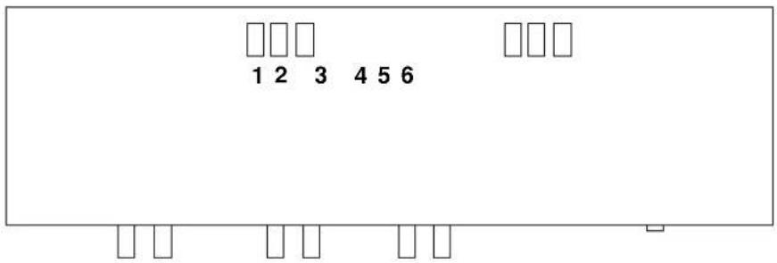
MS 3 DIP-Switch Locations
| 0 = OFF1 = ON | DIPs 1 and 4123456 | DIPs 2 and 5123456 | DIPs 3 and 6123456 |
| MS 1262 - 000010 000100 | |||
| MS 118 000010 -- | |||
DIP-switch settings, MS 3 Audio Controller
SPECIFICATIONS
M20.02 Specifications
INPUT
• TYPE: Electronically balanced
• IMPEDANCE: 47k Ohm
• OPERATING LEVEL 0 dB
• MAX. INPUT: ....+21 dB V (10.5V)
SENSE INPUT
• TYPE:.....Amp output sense
• MAX. INPUT: 110V
OUTPUT
• IMPEDANCE: 50 Ohm
• MAX. OUTPUT: +21dBV (10.5V)
• BANDWIDTH: 35 Hz - 110 Hz, 110 Hz - 160 kHz
• THD: 0.0015%
S/N: 112 dB
CONTROLS
• OUTPUT: -00--+6dB
DIP SWITCHES
• 1-3: Limiter settings low
• 2-4: Limiter settings high
INDICATORS
• 4 LED GREEN: ...... SIGNAL SEND TO OUTPUT
• 4 LED RED: .... LIMITERS IN FUNCTION
• 1 LED BLUE: .... MAIN POWER
POWER SUPPLY
• MAINS VOLTAGE: 100-120/220-240 VAC 50-60 Hz
• POWER CONSUMPTIONS: 9 WATT
• FUSE: 100 mA
- MAINS CONNECTION:....STANDARD IEC RECEPTACLE
PHYSICAL
• DIMENSIONS (HxWxD): 1.75 x 19 x 5 in (44 x 482 x 128 mm)
• NET WEIGHT: 2.2 kg
• SHIPPING WEIGHT: 3.0 kg
M20.03 and MS 3 Specifications
INPUT
• TYPE: ....Differential
• IMPEDANCE: 47k Ohm
• OPERATING LEVEL....0 dB
• MAX. INPUT: 21 dBV (10.5 V)
SENSE INPUT
TYPE: Amp voltage
• MAX. INPUT: 110V
OUTPUT
• IMPEDANCE: 50 Ohm
• MAX. OUTPUT: 20dBV
• BANDWIDTH: 35-110 Hz, 110-1200 Hz, 1.2-120KHz
• THD: 0.0015%
S/N: 112 dB
CONTROLS
• OUTPUT: -00 - +6dB
DIP SWITCHES
• 1-4: Limit sense LOW
• 2-5 ....Limit sense MID
• 3-6....Limit sense HIGH
7-8 (M20.03 only)Eq. HIGH
INDICATORS
- 6 LED GREEN: SIGNAL SEND TO OUTPUT
- 6 LED RED:____ LIMITERS IN FUNCTION
• 1 LED BLUE:.... MAIN POWER
POWER SUPPLY
• MAINS VOLTAGE: 100-120/220-240 VAC 50-60 Hz
• POWER CONSUMPTIONS: 9 WATT
• FUSE: 100 mA
• MAINS CONNECTION: Standard IEC receptacle
PHYSICAL
• DIMENSIONS (HxWxD): 1.75 x 19 x 5 in (44 x 482 x 128 mm)
• NET WEIGHT: 2.2 kg
• SHIPPING WEIGHT: 3.0 kg
- General precautions
- Technical Background
- M20.02, M20.03, AND MS 3 DESIGN CONCEPT
- M20.02 Block Diagram
- M20.03 and MS 3 Block Diagram
- section 3 INSTALLATION
- Mounting
- Connectors
- Voltage Switch
- Mains Connection
- Speaker sense cable connection
- Type 1 wire sets
- Type 2 wire sets
- Fuse Replacement
- Limiter Settings
- CONTROLS
- M20.02 Controls
- M20.03 and MS 3 Controls
- M20.02 Limiter Selection
- M20.03 Limiter & Equalization Selection
- SPECIFICATIONS
- M20.02 Specifications
- INPUT
- SENSE INPUT
- OUTPUT
- DIP SWITCHES
- INDICATORS
- POWER SUPPLY
- PHYSICAL
- M20.03 and MS 3 Specifications
Brand : MARTIN
Model : Mach MS 3
Category : Audio Controller