
01705 - Alarm Vimar - Free user manual and instructions
Find the device manual for free 01705 Vimar in PDF.


| Product Type | Wireless alarm system control panel with LED keypad |
| Brand | Vimar |
| Model | 01705 |
| Keypad Display | Backlit LCD with date, time, zone status, and alarm indicators |
| Keypad Buttons | Numeric keys (0-9), ON, INT, PAR, OFF, ESC, ENT, CLR, and arrow buttons |
| Power Supply | Mains voltage with backup battery (details in manual) |
| Battery Backup | Yes, maintains operation during mains failure |
| Arming Modes | Total, Internal, Partial, Fast Mode |
| Zone Support | Multiple zones (up to 16 or more, configurable) |
| User Codes | Multiple user codes (4-6 digits), admin and standard user |
| Event Memory | Stores up to 500 events with date/time stamp |
| Phone Communication | Voice/SMS alerts via PSTN or GSM module (art. 01706/01708) |
| Remote Access | Via phone call (DTMF) or By-Alarm app (SMS) |
| Output Relays | Relay 1 (general alarm) and Relay 2 (optional), programmable |
| Area Management | Supports multiple areas (up to 2 or more, configurable) |
| Tamper Protection | Control panel tamper detection alerts |
| Quick Functions | Panic, Fire, Doctor alarms (by pressing ON+4, ON+5, ON+6) |
| Walk Test | Integrated walk test mode to verify sensor coverage |
| Programmable Time Switch | Schedules automatic arming/disarming for each area |
| Macro Commands | Custom macros for multi-step operations |
| Dimensions (Keypad) | Approx. 130 x 90 x 30 mm (estimated) |
| Weight | Approx. 200 g (estimated) |
| Operating Temperature | 0°C to 40°C (typical for indoor use) |
| Cleaning | Wipe with a soft dry cloth; do not use liquids or abrasives |
Frequently Asked Questions - 01705 Vimar
User questions about 01705 Vimar
0 question about this device. Answer the ones you know or ask your own.
Ask a new question about this device
Download the instructions for your Alarm in PDF format for free! Find your manual 01705 - Vimar and take your electronic device back in hand. On this page are published all the documents necessary for the use of your device. 01705 by Vimar.
USER MANUAL 01705 Vimar
By-alarm
01705
LED backlit keypad with display
Contents
1. User activations 2
1.1 Buttons, controls and indicators on the keypad 2
1.2 Direct warnings on the display.... 3
1.3 Keypad locking 4
1.4 Keypad unlocking 4
1.5 Indicators on display with User Code. 4
1.6 Total switch-on with Code 5
1.7 Switching off from total switch-on with Code. 5
1.8 Internal or partial switch-on with Code 6
1.9 Switching off from internal or partial switch-on with Code 6
1.10 Switching on the control panel in "FAST MODE" 7
1.11 Switching off the control panel in "FAST MODE" 7
1.12 Switching on different systems with Code 8
1.13 Switching off different systems with Code. 9
1.14 Switching on multiple systems in "FAST MODE" (if programmed) 10
1.15 Switching off multiple systems in "FAST MODE" (if programmed) 11
1.16 How to activate direct alarm calls.... 12
2. Functions and settings 13
2.1 Primary Menu diagram 14
3. Function tree 15
3.1 Events Memory 16
3.1.1 Consulting the Events Memory.... 16
3.1.2 Resetting alerts 1
3.2 Zone management 17
3.2.1 Exclude zone 17
3.2.2 Reinclude zone 17
3.3 User management.... 18
3.3.1 Changing your own User Code 18
3.3.2 Changing other Codes 18
3.4 Phone numbers....19
3.4.1 Change phone numbers 19
3.5 Operations 19
3.5.1 Activate and deactivate outputs 19
3.5.2 Activate Macro instructions 20
3.5.3 Activate and deactivate Programmable Time Switch 21
3.5.4 Activate Overtime 21
3.6 Set Date and Time 2
3.7 System test 22
3.7.1 Phone calls 22
3.7.2 Walk test 23
3.7.3 Keypad buzzer management 23
3.7.4 Activate Relay 1 and Relay 2 23
3.7.5 Check Remaining Credit on GSM 24
3.7.6 SIM expiry 24
3.7.7 Deactivation of Remote Controls 24
4. RFA control panels art. 01700-01703 25
5. By-alarm system remote function access 27
1. USER ACTIVATIONS
1.1 Buttons, controls and indicators on the keypad
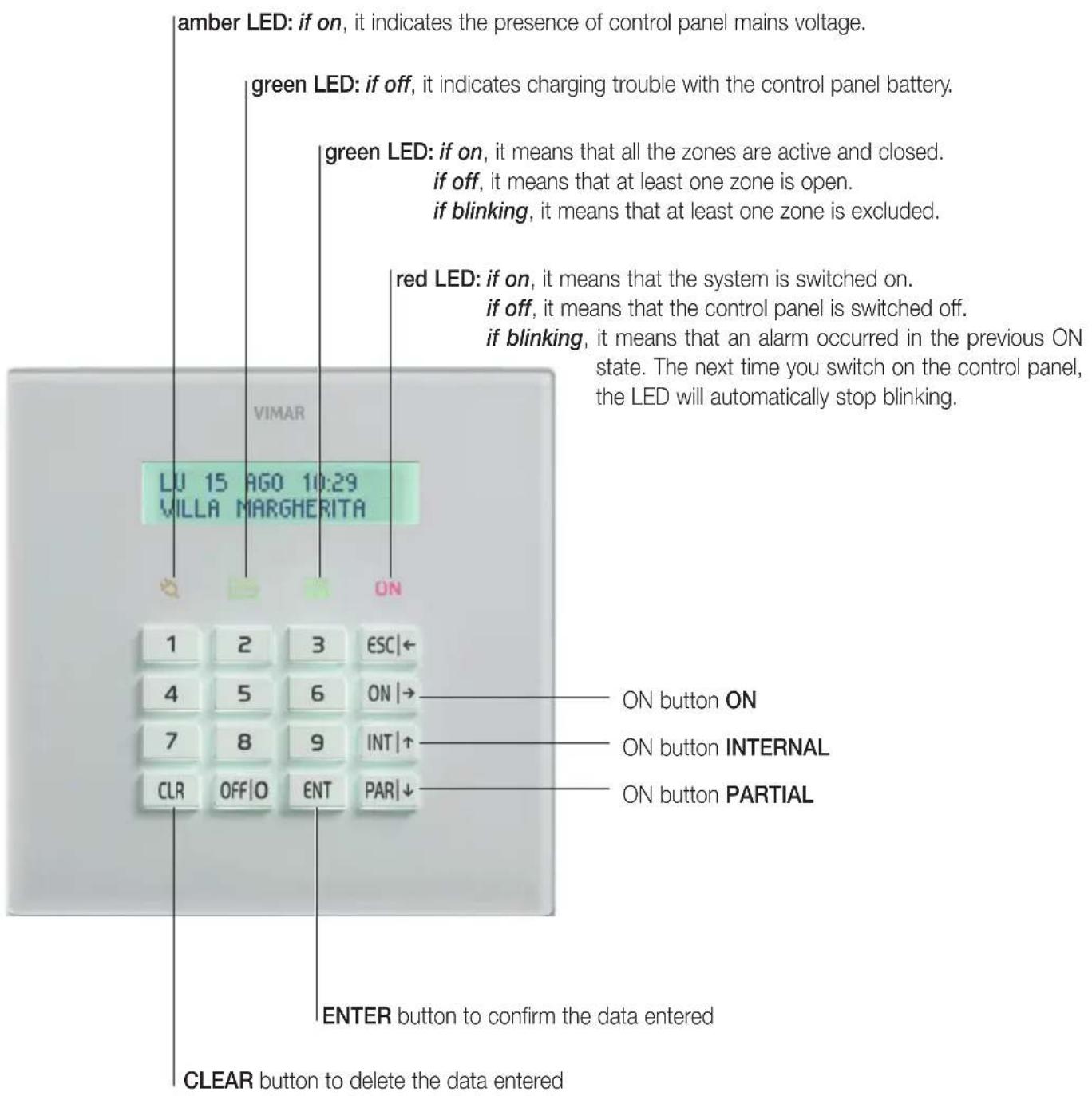
1.2 Direct warnings on the display
- Normally, the display shows the day of the week, the date and time and a second line of information.
TH 08 JUN 19:32 MARGARET'S HOME
Control panel fault statuses, when they occur, appear directly on the display:
- No mains voltage
TH 08 JUN 19:32 NO MAINS
- Battery level
FR 09 MAY 20:12 MALFUNCT. BATTERIES
• Control panel anti-tampering
58 10 MAY 23:37 TAMPER
Similarly, the states of the control panel appear directly on the display and on the keypad; for example:
- Control panel on
CONTROL PANEL ON
- Zone alarm
SA 10 MAY 21:28 ENTRANCE SENSOR
User activations
1.3 Keypad locking
You can lock each keypad with a simple operation to avoid inadvertently pressing buttons or activating the related functions.
a) Press the INT and 7 buttons simultaneously.

1.4 Keypad unlocking
To unlock the keypad you need to perform the same procedure as for locking the keypad.
a) Press the INT and 7 buttons simultaneously.

1.5 Indicators on display with User Code
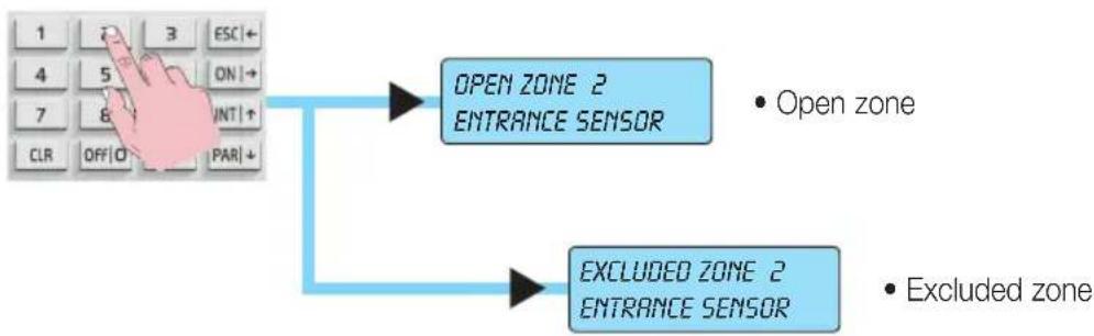
The indicators for any open or excluded zones are displayed, for security reasons, after entering an enabled User Code.
- On entering the User Code, the display will indicate whether some zones are open or have been excluded:
flowchart
graph TD
    A["Hand typing on keyboard"] --> B["OPEN ZONE 2 ENTRANCE SENSOR"]
    A --> C["EXCLUDED ZONE 2 ENTRANCE SENSOR"]
    B --> D["• Open zone"]
    C --> E["• Excluded zone"]
1.6 Total switch-on with Code
a) The display shows the current date and time.
b) Enter the User Code.
c) The display will show all the information relating to the open or excluded zones.
d) Press the button corresponding to total switch-on: ON.
e) The display must not indicate any open zones and the green circuit test LED must be ON. If it is off, it means that at least one zone is open. In this case, do not continue with switching on the control panel or you will trigger a control panel alarm status. The zones indicated as open must be checked and, then, closed or excluded (see "Zone management" on page 17).
f) Press the ENT button to confirm switching on the control panel in ON mode.
The red LED on the keypad will light up.
MARGARET'S HOME READY (MENU 9)
ON |→
SWITCHING ON ENT=YES ESC=NO
ENT
CONTROL PANEL ON
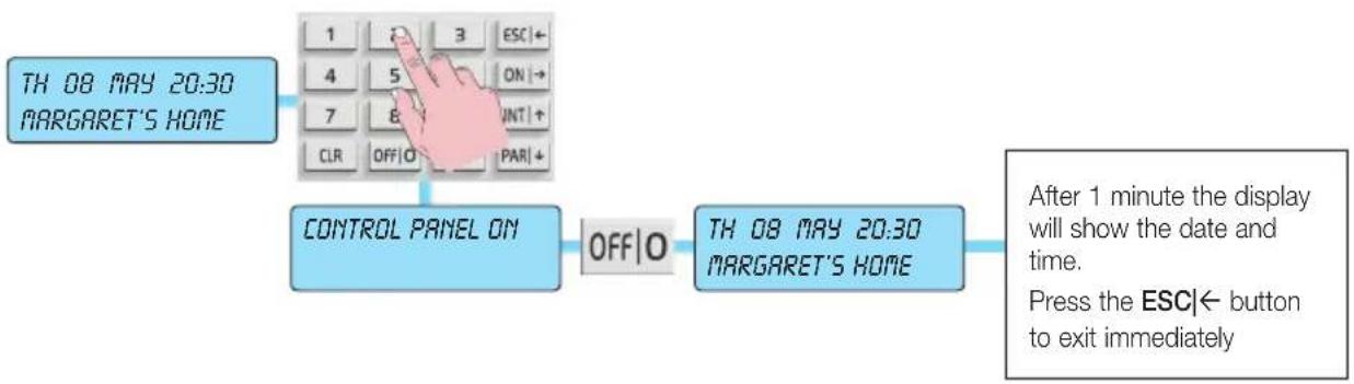
1.7 Switching off from total switch-on with Code
a) The display shows the current date and time.
b) Enter the User Code.
c) The display will confirm recognition of the User Code and show the status of control panel switch-on; then, press the OFF|0 button.
• The red LED will go out on the keypad.
If it blinks instead, it means there has been an alarm in the previous switch-on state; in this case the display will also indicate which zone caused it. This alarm memory will be automatically reset the next time you switch on.
flowchart
graph TD
    A["TH 08 MAY 20:30 MARGARET'S HOME"] --> B["1 2 3 ESC←"]
    B --> C["4 5 ON→"]
    C --> D["7 8 INT+"]
    D --> E["CLR OFF|O PAR+"]
    E --> F["CONTROL PANEL ON"]
    F --> G["OFF|O"]
    G --> H["TH 08 MAY 20:30 MARGARET'S HOME"]
    H --> I["After 1 minute the display will show the date and time. Press the ESC← button to exit immediately"]
User activations
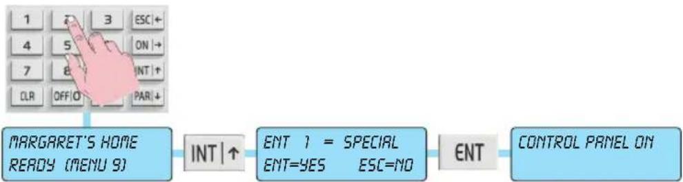
1.8 Internal or partial switch-on with Code
a) The display shows the current date and time.
b) Enter the User Code.
c) The display will give all the information relating to the open or excluded zones.
d) Press the button corresponding to INTernal or PARtial switch-on.
e) The display must not indicate any open zones and the green circuit test LED must be ON or blinking to signal the excluded zones.
If instead it is off, it means that at least one zone is open. In this case, do not continue with switching on the control panel or you will trigger a control panel alarm status. The zones indicated as open must be checked and, then, closed or excluded (see "Zone management" on page 17).
f) Press the ENT button to confirm switching on in INTernal or PARtial mode.
- N.B.: Press button 1 to activate special switch-on; this switch-on mode automatically clears all the output delays related to the timed lines.
The red LED on the keypad will light up.
flowchart
graph LR
    A["1 2 3 ESC +"] --> B["4 5 ON →"]
    B --> C["7 8 INT ↑"]
    C --> D["CLR OFFIO PAR ↓"]
    E["MARGARET'S HOME READY (MENU 9)"] --> F["INT ↑"]
    F --> G["ENT 1 = SPECIAL\nENT=YES ESC=NO"]
    G --> H["ENT"]
    H --> I["CONTROL PANEL ON"]
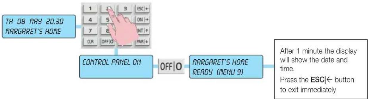
1.9 Switching off from internal or partial switch-on with Code
a) The display shows the current date and time.
b) Enter the User Code.
c) The display will confirm recognition of the User Code and show the status of control panel switch-on; then, press the OFF|0 button.
- The red UN LED will go out on the keypad. If it blinks instead, it means there has been an alarm in the previous switch-on state; in this case the display will also indicate which zone caused it; this alarm memory will be automatically reset the next time you switch on.
flowchart
graph TD
    A["TH 08 MAY 20:30 MARGARET'S HOME"] --> B["1 2 3 ESC+"]
    B --> C["4 5 ON+"]
    C --> D["7 8 INT+"]
    D --> E["CLR OFF|O PAR+"]
    E --> F["CONTROL PANEL ON"]
    F --> G["OFF|O"]
    G --> H["MARGARET'S HOME READY (MENU 9)"]
    H --> I["After 1 minute the display will show the date and time. Press the ESC← button to exit immediately"]
User activations
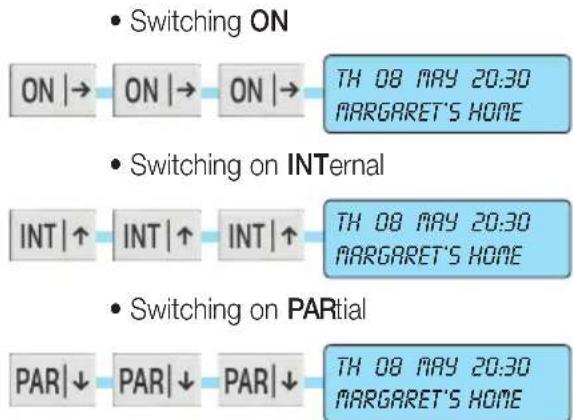
1.10 Switching on the control panel in "FAST MODE"
If you enabled fast switch-on, you can switch on the control panel without having to enter the User Code.
a) The display shows the current date and time.
b) Press the button corresponding to the desired switch-on 3 times:
flowchart
graph LR
    A["ON |→"] --> B["ON |→"] --> C["ON |→"] --> D["TH 08 MAY 20:30 MARGARET'S HOME"]
    E["INT |↑"] --> F["INT |↑"] --> G["INT |↑"] --> H["TH 08 MAY 20:30 MARGARET'S HOME"]
    I["PAR |↓"] --> J["PAR |↓"] --> K["PAR |↓"] --> L["TH 08 MAY 20:30 MARGARET'S HOME"]
With fast INTernal and PARtial switching on, the exit and re-entry times for the timed lines will always be available
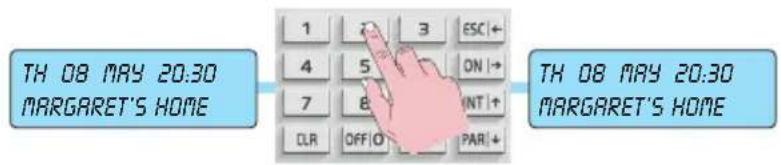
1.11 Switching off the control panel in "FAST MODE"
a) The display shows the current date and time.
b) Enter the User Code.
c) The control panel will switch off immediately, showing the current date and time.
The red ON LED will go out on the keypad. If it blinks instead, it means there has been an alarm in the previous switch-on state; in this case the display will also indicate which zone caused it; this alarm memory will be automatically reset the next time you switch on.
User activations
1.12 Switching on different systems with Code
a) The display shows the current date and time.
b) Enter the User Code.
c) Only on the keypad where you are working, the display will show only the Areas associated with the entered Code and faults will only be shown on the display if they occur, by means of graphic symbols.
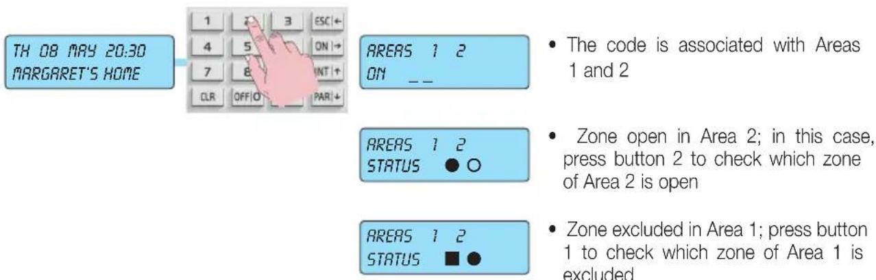
d) If you want to switch on Area 1, press button 1 to select the Area.
e) The display will show "System Name READY".
f) Press the ON, INTernal or PARtial button to switch on the selected Area.
g) Press the ENT button to confirm. Switch-on in the selected mode will be indicated on Area 1. [O] for ON, [I] for INTernal and [P] for PARtial.
h) Proceed in a similar fashion to switch on the other Areas.
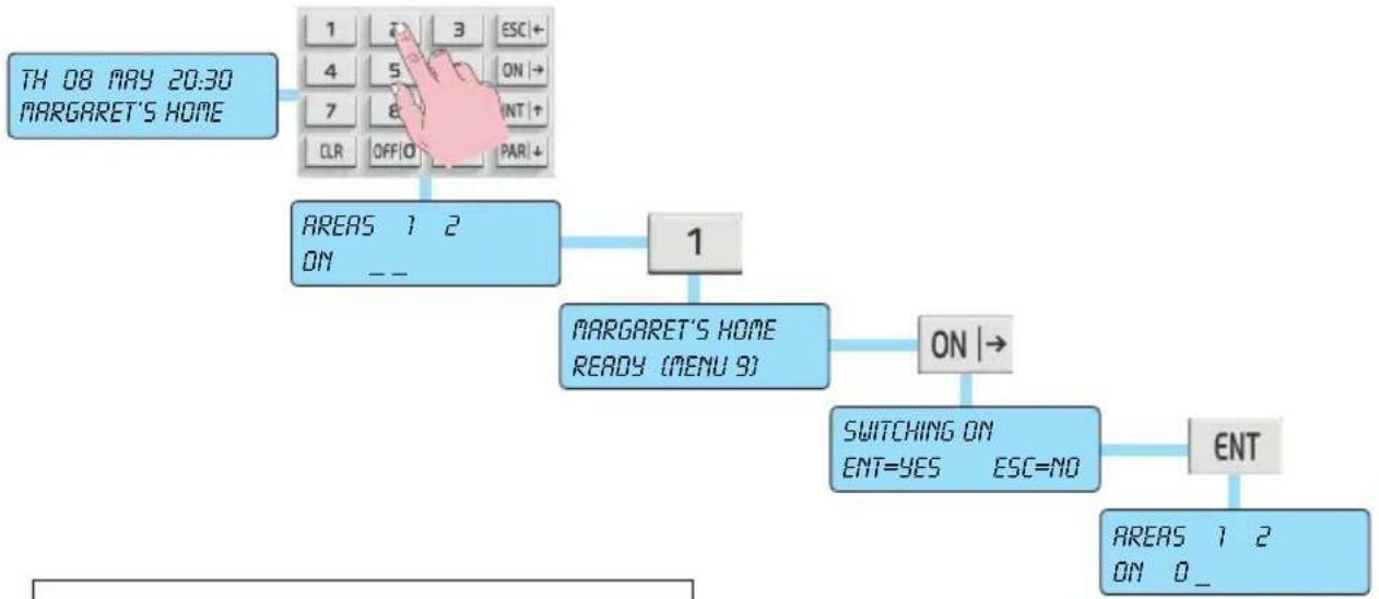
flowchart
graph TD
    A["TH 08 MAY 20:30 MARGARET'S HOME"] --> B["1 ON 3 ESC+"]
    B --> C["4 5 ON →"]
    C --> D["7 8 INT +"]
    D --> E["CLR OFF/O PAR ↓"]
    E --> F["AREAS 1 2 ON --"]
    F --> G["1 MARGARET'S HOME READY (MENU 9)"]
    G --> H["ON →"]
    H --> I["SWITCHING ON ENT=YES ESC=NO"]
    I --> J["ENT"]
    J --> K["AREAS 1 2 ON 0 _"]
Example of switching on Area 1 in ON mode
User activations
1.13 Switching off different systems with Code
a) The display shows the current date and time.
b) Enter the User Code.
c) Only on the keypad where you are working, the display will show only the Areas associated with the entered Code and the switch-on modes for each single Area. [O] for ON, [I] for INTernal and [P] for PARtial.
d) If you want to switch off Area 1, press button 1 to select the Area.
e) The display will show "CONTROL PANEL ON".
f) Press the OFF|0 button to switch off the Area. The display will return to showing the status of all the systems.
g) In a similar manner, you can switch off the other Areas.
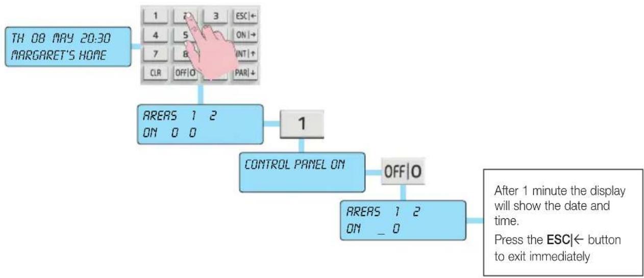
flowchart
graph TD
    A["TH 08 MAY 20:30 MARGARET'S HOME"] --> B["1 7 3 ESC←"]
    B --> C["4 5 ON→"]
    C --> D["7 8 INT+"]
    D --> E["CLR OFF|O | PAR|+"]
    E --> F["AREAS 1 2 ON 0 0"]
    F --> G["1"]
    G --> H["CONTROL PANEL ON"]
    H --> I["OFF|O"]
    I --> J["AREAS 1 2 ON _ 0"]
    J --> K["After 1 minute the display will show the date and time. Press the ESC← button to exit immediately"]
User activations
1.14 Switching on multiple systems in "FAST MODE" (if programmed)
a) The display shows the current date and time.
b) Enter the User Code.
c) The display will show only the Areas associated with the entered Code and faults will be displayed, by means of graphic symbols, only if they occur.
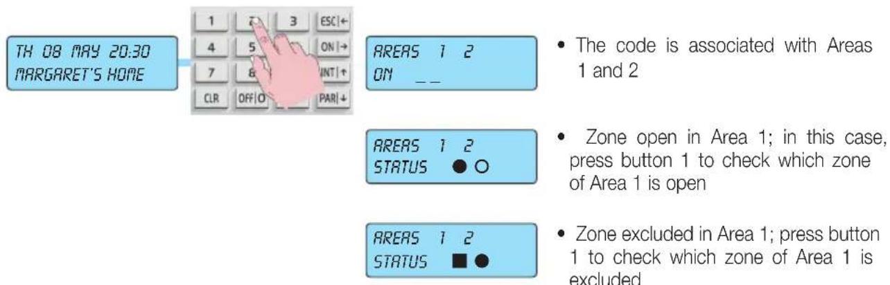
d) If you want to switch on all the Areas in a single mode (ON, INTernal or PARtial), you need to press the button corresponding to the chosen mode.
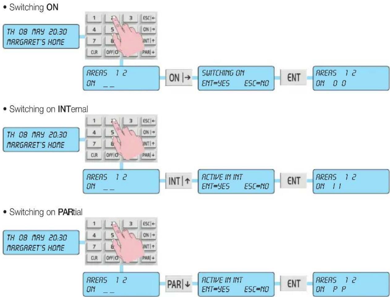
flowchart
graph TD
    A["TH 08 MAY 20:30 MARGARET'S HOME"] --> B["1 3 ESC←"]
    B --> C["4 5 ON→"]
    C --> D["7 8 INT+"]
    D --> E["CLR OFF|O PAR|+"]
    E --> F["AREAS 1 2 ON --"]
    F --> G["ON |→"]
    G --> H["SWITCHING ON ENT=YES ESC=NO"]
    H --> I["ENT"]
    I --> J["AREAS 1 2 ON 0 0"]

    K["TH 08 MAY 20:30 MARGARET'S HOME"] --> L["1 3 ESC←"]
    L --> M["4 5 ON→"]
    M --> N["7 8 INT+"]
    N --> O["CLR OFF|O PAR|+"]
    O --> P["AREAS 1 2 ON --"]
    P --> Q["INT |↑"]
    Q --> R["ACTIVE IN INT ENT=YES ESC=NO"]
    R --> S["ENT"]
    S --> T["AREAS 1 2 ON 1 1"]

    U["TH 08 MAY 20:30 MARGARET'S HOME"] --> V["1 3 ESC←"]
    V --> W["4 5 ON→"]
    W --> X["7 8 INT+"]
    X --> Y["CLR OFF|O PAR|+"]
    Y --> Z["AREAS 1 2 ON --"]
    Z --> AA["PAR|↓"]
    AA --> AB["ACTIVE IN INT ENT=YES ESC=NO"]
    AB --> AC["ENT"]
    AC --> AD["AREAS 1 2 ON PP"]
User activations
1.15 Switching off multiple systems in "FAST MODE" (if programmed)
a) The display shows the current date and time.
b) Enter the User Code.
c) The display will show only the Areas associated with the entered Code and the switch-on mode for each single Area; [O] for ON, [I] for INTernal and [P] for PARtial.
f) Press the OFF|0 button to switch off all the Areas simultaneously.
• Examples of general shutdown:
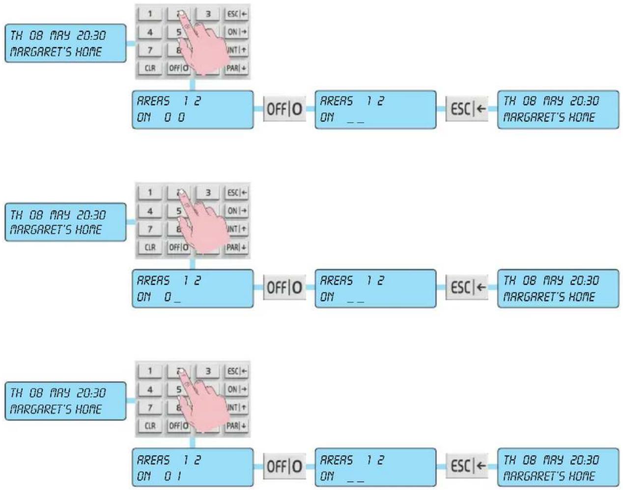
flowchart
graph TD
    A["TH 08 MAY 20:30 MARGARET'S HOME"] --> B["1 ON 0 0"]
    B --> C["AREAS 1 2 ON 0 0"]
    C --> D["OFF|O"]
    D --> E["AREAS 1 2 ON __"]
    E --> F["ESC|← TH 08 MAY 20:30 MARGARET'S HOME"]
    G["TH 08 MAY 20:30 MARGARET'S HOME"] --> H["1 ON 0_"]
    H --> I["AREAS 1 2 ON _"]
    I --> J["OFF|O"]
    J --> K["AREAS 1 2 ON __"]
    K --> L["ESC|← TH 08 MAY 20:30 MARGARET'S HOME"]
    M["TH 08 MAY 20:30 MARGARET'S HOME"] --> N["1 ON 0 1"]
    N --> O["AREAS 1 2 ON _"]
    O --> P["OFF|O"]
    P --> Q["AREAS 1 2 ON __"]
    Q --> R["ESC|← TH 08 MAY 20:30 MARGARET'S HOME"]
User activations
1.16 How to activate direct alarm calls
There are particular emergency situations that, at any time, should trigger the corresponding telephone communications extremely quickly; for this reason, simply by pressing certain buttons, you can invoke emergency functions:
PANIC:


Keeping the ON and 4 buttons pressed activates the outputs programmed as "panic message" and a phone call is made to the programmed numbers, communicating a PANIC ALARM, that can be associated with an emergency status for attempted robbery.
FIRE:


Keeping the ON and 5 buttons pressed activates the outputs programmed as "fire message" and a phone call is made to the programmed numbers, communicating a FIRE ALARM.
DOCTOR:


Keeping the ON and 6 buttons pressed activates the outputs programmed as "doctor message" and a phone call is made to the programmed numbers, communicating a DOCTOR CALL.
Functions and settings
2. FUNCTIONS AND SETTINGS
Directly from the keypad you can activate functions of control and customization.
To reach the User functions menus:
With Code associated with a system
a) The display shows the current date and time.
b) Enter the User Code.
c) Press button 9 to reach the first User menu.
- Using the arrow buttons INT|↑ and PAR|↓ you move forward or backward in viewing the various User Functions; with theENT button you enter the function's configuration mode.
- All the functions are illustrated on the next page.

flowchart
graph LR
    A["TH 08 MAY 20:30 MARGARET'S HOME"] --> B["1 2 3 ESC←"]
    B --> C["4 5 ON→"]
    C --> D["7 8 INT+"]
    D --> E["CLR OFF/O PAR+"]
    E --> F["MARGARET'S HOME READY {MENU=9}"]
    F --> G["9"]
    G --> H["EVENTS MEMORY ▲ ▼ ENT"]
With Code associated with multiple systems
a) The display shows the current date and time.
b) Enter the User Code.
c) Press the button that corresponds to an Area to "enter" the related system management.
d) Press button 9 to reach the first User menu.
- Using the arrow buttons INT|↑ and PAR|↓ you move forward or backward in viewing the various User Functions; with theENT button you enter the function's configuration mode.
- All the functions are illustrated on the next page.
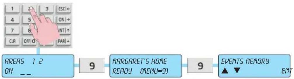
flowchart
graph LR
    A["1 2 3 ESC"] --> B["9"]
    C["4 5 ON"] --> B
    D["7 8 INT"] --> B
    E["CLR OFF"] --> B
    F["PAR"] --> B
    G["AREAS 1 2 ON --"] --> B
    H["MARGARET'S HOME READY (MENU=9)"] --> I["9"]
    J["EVENTS MEMORY ▲▼ ENT"] --> I
Functions and settings
2.1 Primary Menu diagram
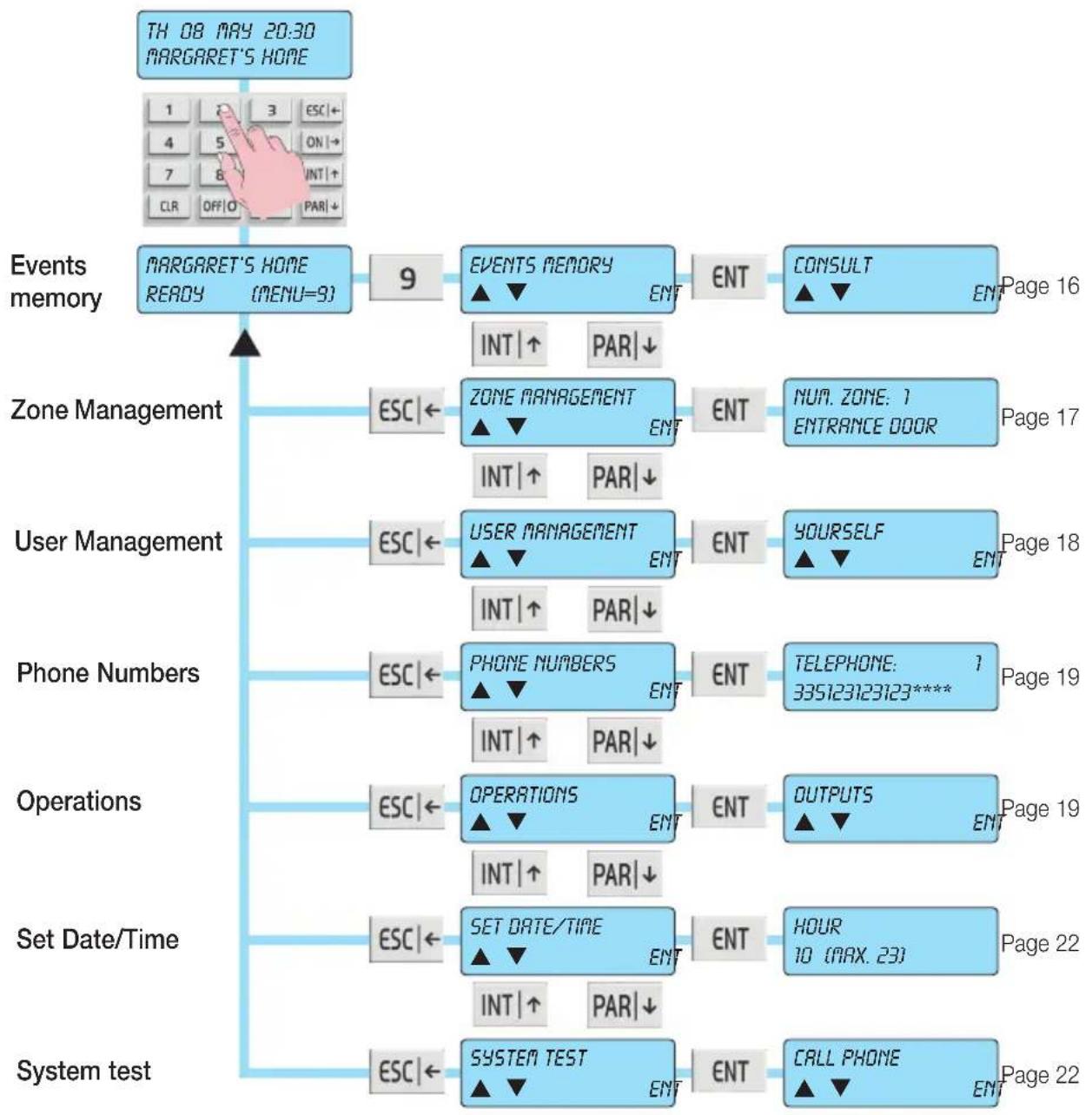
flowchart
graph TD
    A["TH 08 MAY 20:30 MARGARET'S HOME"] --> B["Events memory"]
    B --> C["MARGARET'S HOME READY (MENU=9)"]
    C --> D["9"]
    D --> E["EVENTS MEMORY ▲▼ ENT"]
    E --> F["ENT"]
    F --> G["CONSULT ▲▼ ENT"]
    G --> H["Page 16"]
    D --> I["INT|↑ PAR↓"]
    I --> J["Zone Management"]
    J --> K["ESC|←"]
    K --> L["ZONE MANAGEMENT ▲▼ ENT"]
    L --> M["ENT"]
    M --> N["NUM. ZONE: 1 ENTRANCE DOOR"]
    N --> O["Page 17"]
    J --> P["INT|↑ PAR↓"]
    P --> Q["User Management"]
    Q --> R["ESC|←"]
    R --> S["USER MANAGEMENT ▲▼ ENT"]
    S --> T["ENT"]
    T --> U["YOURSELF ▲▼ ENT"]
    U --> V["Page 18"]
    Q --> W["INT|↑ PAR↓"]
    W --> X["Phone Numbers"]
    X --> Y["ESC|←"]
    Y --> Z["PHONE NUMBERS ▲▼ ENT"]
    Z --> AA["ENT"]
    AA --> AB["TELEPHONE: 1 335123123123****"]
    AB --> AC["Page 19"]
    Z --> AD["INT|↑ PAR↓"]
    AD --> AE["Operations"]
    AE --> AF["ESC|←"]
    AF --> AG["OPERATIONS ▲▼ ENT"]
    AG --> AH["ENT"]
    AH --> AI["OUTPUTS ▲▼ ENT"]
    AI --> AJ["Page 19"]
    AF --> AK["INT|↑ PAR↓"]
    AK --> AL["Set Date/Time"]
    AL --> AM["ESC|←"]
    AM --> AN["SET DATE/TIME ▲▼ ENT"]
    AN --> AO["ENT"]
    AO --> AP["HOUR 10 (MAX. 23)"]
    AP --> AQ["Page 22"]
    AL --> AR["INT|↑ PAR↓"]
    AR --> AS["System test"]
    AS --> AT["ESC|←"]
    AT --> AU["SYSTEM TEST ▲▼ ENT"]
    AU --> AV["ENT"]
    AV --> AW["CALL PHONE ▲▼ ENT"]
    AW --> AX["Page 22"]
| Function of the buttons | ||
| ESC|← button | ENT button | INT|↑ and PAR| ↓ button |
| • takes you back a step.• repeated pressing takes you out of configuration mode | • takes you into the Menu displayed at that time• confirms the data entered | • take you respectively down or up in the diagram of the Menus |
3. FUNCTION TREE
3.1 Events Memory
3.1.1 Consult
3.1.2 Reset alerts
3.2 Zone management
3.2.1 Zone number
- Exclude
- Reinclude
3.3 User Management
3.3.1 Changing your own User Code
3.3.2 Other codes
3.4 Phone numbers
3.5 Operations
3.5.1 Outputs
3.5.2 Macro
3.5.3 Programmable time switch
3.5.4 Overtime
3.6 Set Date and Time
3.7 System test
3.7.1 Call phone
3.7.2 Walk test
3.7.3 Buzzer ON/OFF
3.7.4 Activate relay 1
3.7.5 Activate relay 2
3.7.6 Remaining credit
3.7.7 SIM expiry
Function tree
3.1 Events Memory
The control panel has a memory where everything that happens to the control panel is recorded with the date and time; saved events are automatically updated, always deleting the oldest one. The control panel art. 01700 saves up to 200 events, while the control panel art. 01703 saves up to 500.
- The arrow buttons INT|↑ and PAR|↓ are used for scrolling, viewing all the options in this menu.
- With the ESC|← button you exit the menu.
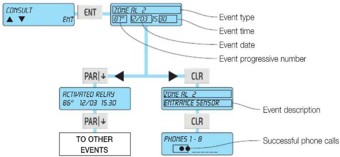
3.1.1 Consulting the Events Memory
a) The display shows the Menu for consulting the Events memory.
g) Press the ENT button to enter.
c) If the code that allowed access is enabled for this function, the display will show the Menu for consulting the internal memory of the control panel.
d) Press the ENT button to enter.
- The last of the saved events, the most recent one, is displayed; with the PAR|↓ arrow you go back in time in viewing the memory, whereas with the INT|↑ arrow you move forward to the most recent event.
- With the CLR button you can view other data on the event shown.
e) Press the ESC|← button to exit Consulting the Events Memory.
flowchart
graph TD
    A["CONSULT"] --> B["ENT"]
    B --> C["ZONE AL 2\n87° 12/03 15:30"]
    C --> D["CLR"]
    D --> E["TO OTHER EVENTS"]
    D --> F["PHONES 1 - 8"]
    C --> G["PAR↓"]
    G --> H["ACTIVATED RELAY\n86° 12/03 15:30"]
    H --> I["PAR↓"]
    I --> J["Event description"]
    C --> K["Event type"]
    C --> L["Event time"]
    C --> M["Event date"]
    C --> N["Event progressive number"]
    D --> O["CLR"]
    O --> P["Successful phone calls"]
Function tree
3.1.2 Resetting alerts
a) The display shows the Menu for resetting alerts
b) Press the ENT button to reset the alarm alerts on the keypads.
c) Confirm with the ENT button if you want to continue.
d) Press the ESC|← button to exit resetting the alerts.

flowchart
graph LR
    A["RESET ALERTS"] --> B["ENT"]
    B --> C["SURE P"]
    C --> D["ENT=YES"]
    C --> E["ESC=NO"]
3.2 Zone management
With this function you can exclude and reinclude the alarm management zones.
Caution: Excluded zones cannot generate any control panel alarm status.
3.2.1 Exclude zone
a) Scrolling with the navigation buttons INT|↑ and PAR|↓, select the zone you want to exclude from the alarm.
b) Confirm with the ENT button or press the ESC|← button to exit without excluding.

flowchart
graph LR
    A["ZONE MANAGEMENT ▲ ▼"] --> B["ENT"]
    B --> C["NUM. ZONE: 3 ROOM WINDOW"]
    C --> D["ENT"]
    D --> E["SYSTEM READY EXCLUDE P"]
    E --> F["ENT"]
    F --> G["NUM. ZONE: 3 (ESC) ROOM WINDOW"]
3.2.2 Reinclude zone
a) Scrolling with the navigation buttons INT|↑ and PAR|↓, select the zone you want to reinclude in the alarm.
b) Confirm with the ENT button or press the ESC|← button to exit without reincluding.

flowchart
graph TD
    A["ZONE MANAGEMENT ▲ ▼"] --> B["ENT"]
    B --> C["NUM. ZONE: 3 (ESC) ROOM WINDOW"]
    C --> D["ENT"]
    D --> E["EXCLUDED ZONE REINCLUDE ?"]
    E --> F["ENT"]
    F --> G["NUM. ZONE: 3 ROOM WINDOW"]
Function tree
3.3 User Management
The control panel can be managed by User Codes that can be changed by the User.
- The arrow buttons INT|↑ and PAR|↓ are used for scrolling, viewing all the options in this menu.
- With the ESC|← button you exit the menu.
3.3.1 Changing your own User Code
a) If the code that allowed access is enabled for this function, the display will show the ability for you to change your code.
g) Press the ENT button to enter.
c) Press the CLR button to delete the current code.
d) Enter the new Code.
e) Press the ENT button to confirm.
f) Press the ESC|← button to exit changing your own code.

flowchart
graph LR
    A["YOURSELF ▲▼"] --> B["ENT"]
    B --> C["YOURSELF: ----"]
    C --> D["CLR"]
    D --> E["YOURSELF ***** * * * * * *"]
    E --> F["1 3 ESC+"]
    E --> G["4 5 ON+"]
    E --> H["7 8 INT+"]
    E --> I["CLR OFF O PAR+"]
    E --> J["ENT"]
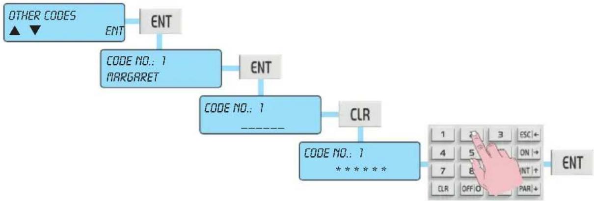
3.3.2 Changing other codes
a) If the code that allowed access is enabled for this function, the display will show the ability for you to change other Codes.
g) Press the ENT button to enter.
c) Select the Code that you want to change by scrolling with the INT|↑ and PAR|↓ buttons.
d) Press the ENT button to confirm.
e) Press the CLR button to delete the current code.
f) Enter your new Code.
g) Press the ENT button to confirm.
h) Press the ESC|← button to exit changing the code.
flowchart
graph TD
    A["OTHER CODES ▲ ▼"] --> B["ENT"]
    B --> C["CODE NO.: 1 MARGARET"]
    C --> D["ENT"]
    D --> E["CODE NO.: 1 ----"]
    E --> F["CLR"]
    F --> G["CODE NO.: 1 *****"]
    G --> H["1 2 3 ESC+4 5 ON+7 8 INT+CLR OFF+O PAR+"]
    H --> I["ENT"]
Function tree
3.4 Phone numbers
3.4.1 Change phone numbers
a) The display shows the Menu for Changing phone numbers.
g) Press the ENT button to enter.
a) If the code that allowed access is enabled for this function, the 16 phone numbers can be changed.
d) With the INT|↑ and PAR|↓ arrow buttons you can scroll through the various phone numbers with the relevant view.
e) To change the phone number, press the CLR button, write the new number and press the ENT button to confirm.
f) Press the ESC|← button to exit changing phone numbers

flowchart
graph LR
    A["TELEFONO 1\n33512121212*****"] --> B["ENT"]
    B --> C["CLR"]
    C --> D["TELEFONO 1\n**********"]
    D --> E["1\n4\n7\nCLR"]
    E --> F["3\n5\n8\nOFF/O"]
    F --> G["ESC\nON\nINT\nPAR\n+"]
    G --> H["ENT"]
3.5 Operations
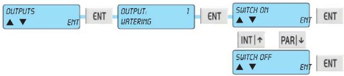
3.5.1 Activate and Deactivate Outputs
a) The display shows the Menu for Activating the Outputs.
g) Press the ENT button to enter.
c) The arrow buttons INT|↑ and PAR|↓ are used for scrolling, viewing each single output with its description.
d) Press the ENT button to enter the chosen output.
e) With the INT|↑ and PAR|↓ arrow buttons you select whether to activate or deactivate the output.
f) Press the ENT button to confirm.
g) Press the ESC|← button to exit the Outputs Menu.
flowchart
graph LR
    A["OUTPUTS ▲▼ ENT"] --> B["OUTPUT: 1 WATERING"]
    B --> C["ENT"]
    C --> D["SWITCH ON ▲▼ ENT"]
    D --> E["INT |↑ PAR|↓"]
    D --> F["SWITCH OFF ▲▼ ENT"]
    F --> G["ENT"]
Function tree
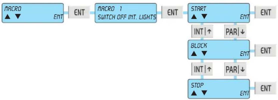
3.5.2 Activate Macro instructions
Macros are instructions formed by a set of commands; they are programmed in the control panel and can be activated in one easy step.
Each Macro-Instruction is identified by a character string that best explains the function of the macro.
a) The display shows the Menu for Activating the Macros.
g) Press the ENT button to enter.
c) The arrow buttons INT|↑ and PAR|↓ are used for scrolling, viewing each single macro with its description.
d) Press the ENT button to enter the chosen macro.
e) The INT|↑ and PAR|↓ arrow buttons are used for scrolling, viewing all the possible commands:
- Start: activates the macro.
- Stop: stops the execution of the macro, resets it and moves the pointer to the first command.
- Block: stops the execution of the macro and restarts it from where you left off.
f) Press the ESC|← button to exit the Macro activation menu.
flowchart
graph LR
    A["MACRO ▲▼ ENT"] --> B["ENT"]
    B --> C["MACRO 1 SWITCH OFF INT. LIGHTS"]
    C --> D["ENT"]
    D --> E["START ▲▼ ENT"]
    E --> F["ENT"]
    F --> G["INT |↑ PAR↓"]
    G --> H["BLOCK ▲▼ ENT"]
    H --> I["ENT"]
    I --> J["INT |↑ PAR↓"]
    J --> K["STOP ▲▼ ENT"]
    K --> L["ENT"]
3.5.3 Activate and deactivate Programmable Time Switch
a) The display shows the Menu for Activating and Deactivating the programmable time switch.
g) Press the ENT button to enter.
c) If the code that allowed access is enabled for this function, with the arrow buttons INT|↑ and PAR|↓ you scroll to view the programmable time switches associated with each single area.
d) Press the ENT button to confirm your choice.
e) With the INT|↑ and PAR|↓ arrow buttons you select whether to activate or deactivate the selected programmable time switch.
Caution: If the programmable time switch is not active, the control panel will not run the programmed on/off commands for that area.
f) Press the ESC|← button to exit the programmable time switch management menu.
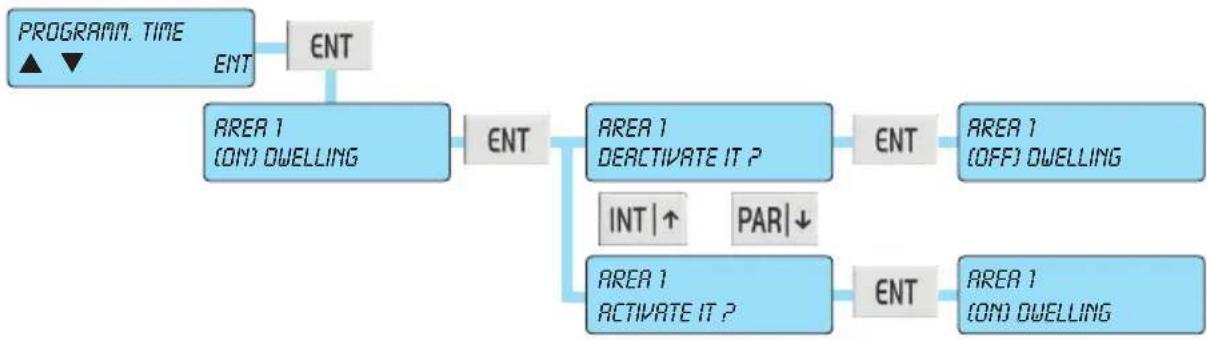
flowchart
graph TD
    A["PROGRAM. TIME"] --> B["ENT"]
    B --> C["AREA 1\n(ON) DWELLING"]
    C --> D["ENT"]
    D --> E["AREA 1\nDEACTIVATE IT P"]
    E --> F["ENT"]
    F --> G["AREA 1\n(OFF) DWELLING"]
    E --> H["INT |↑"]
    E --> I["PAR |↓"]
    H --> J["AREA 1\nACTIVATE IT P"]
    J --> K["ENT"]
    K --> L["AREA 1\n(ON) DWELLING"]
3.5.4 Activate Overtime
a) The display shows the Menu for Activating Overtime.
g) Press the ENT button to enter.
c) If the code that allowed access is enabled for this function, pressing the ENT button will activate overtime that will shift the time for automatic switch-on via the programmable time switch by one hour.
Caution: • This function is only active during the warning period.
- You can add overtime for 3 times in a row, after which shifting the switch-on time will no longer be accepted by the control panel.
d) Press the ESC|← button to exit the overtime enabling menu.

flowchart
graph LR
    A["OVERTIME ▲▼"] --> B["ENT"]
    B --> C["ART"]
    C --> D["AREA 1 DOWELLING"]
    D --> E["ENT"]
    E --> F["AREA 1 ACTIVATE IT P"]
    F --> G["ENT"]
    G --> H["AREA 1 (OVT) DWELLING"]
Function tree
3.6 Set Date and Time
a) The display shows the Menu for Changing the Date.
g) Press the ENT button to enter.
c) The control panel time will be shown; use the arrow buttons INT|↑ and PAR|↓ to scroll through the menus that will show the minutes, day, month and year.
d) To update the time you simply need to write the correct value. The day of the week (Monday, etc.) is automatically calculated by the control panel.
e) Press the ESC|← button to exit changing the date.
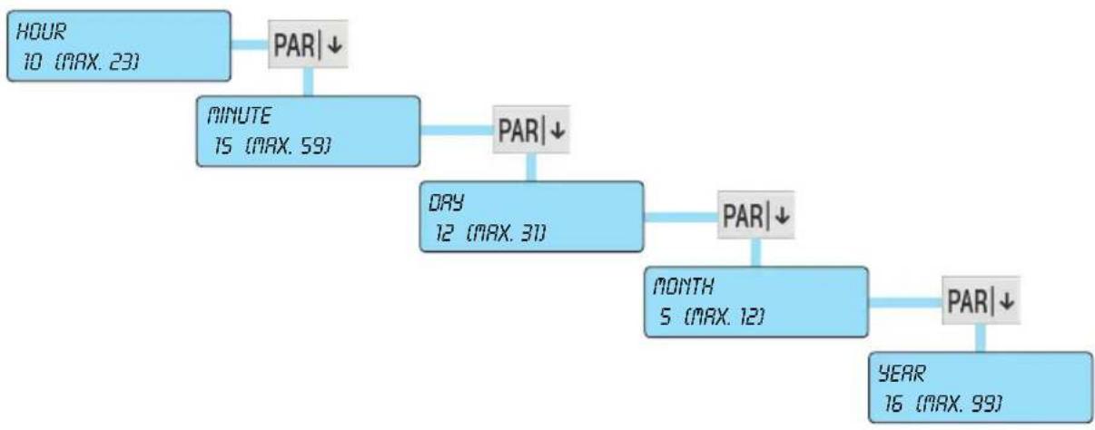
flowchart
graph TD
    A["HOUR 10 (MAX. 23)"] --> B["PAR↓"]
    B --> C["MINUTE 15 (MAX. 59)"]
    C --> D["PAR↓"]
    D --> E["DAY 12 (MAX. 31)"]
    E --> F["PAR↓"]
    F --> G["MONTH 5 (MAX. 12)"]
    G --> H["PAR↓"]
    H --> I["YEAR 16 (MAX. 99)"]
3.7 System test
3.7.1 Phone calls
a) The display shows the Menu for phone calls.
g) Press the ENT button to enter.
c) The arrow buttons INT|↑ and PAR|↓ are used for scrolling, viewing each single phone number.
d) With the ENT button you activate the selected phone number.
e) Press the ESC|← button to exit the phone call test menu.

flowchart
graph LR
    A["CALL PHONE ▲ ▼"] --> B["ENT"]
    B --> C["TELEPHONE 1 335123123123****"]
    C --> D["ENT"]
    D --> E["TELEPHONE 1 PHONE CALL 1"]
Function tree
3.7.2 Walk Test
a) The display shows the Menu for the entry test.
g) Press the ENT button to enter.
- Open the monitored doors and windows and walk in the area protected by the volumetric sensors.
- With each new detection, the keypad will sound and the symbol will remain saved corresponding to each zone activated by the test.
- The arrow buttons INT|↑ and PAR|↓ are used for scrolling through the zones in groups of 8.
- The zones not marked by the ● symbol cannot trigger an alarm condition.
c) Press the ESC|← button to exit the entry test menu.

flowchart
graph TD
    A["WALK TEST ▲▼"] --> B["ENT"]
    B --> C["ZONES 1-8 ----"]
    C --> D["ZONES 1-8 •_●●_●_"]
    D --> E["PAR↓"]
    E --> F["ZONES 9-16 •_●_"]
    F --> G["PAR↓"]
3.7.3 Keypad buzzer management
a) The display shows the Menu for silencing the buzzer for the keypad on which you are working.
g) Press the ENT button to enter.
- Press the CLR button once to cut off the sound; press CLR again to re-enable the sound.
c) Press the ESC|← button to exit the system test menu.

flowchart
graph LR
    A["BUZZER ON - OFF"] --> B["ENT"]
    B --> C["BUZZER ON - OFF"]
    C --> D["CLR=TOGGLE"]
    D --> E["CLR"]
3.7.4 Activate Relay 1 and Relay 2
a) The display shows the Menu for Output Relay 1, which is the one related to the general alarm output, and for Output Relay 2, which is the one related to optional alarms; in this way you can test the alarm warnings.
g) Press the ENT button to enter.
c) The ENT button activates, while the CLR button deactivates.
d) Press the ESC|← button to exit the Relay 1 test menu.
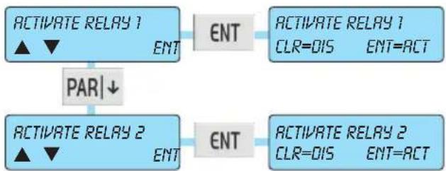
flowchart
graph TD
    A["ACTIVATE RELAY 1<br>▲▼"] --> B["ENT"]
    C["PAR↓"] --> D["ACTIVATE RELAY 2<br>▲▼"]
    B --> E["ACTIVATE RELAY 1<br>CLR=DIS ENT=ACT"]
    D --> F["ACTIVATE RELAY 2<br>CLR=DIS ENT=ACT"]
3.7.5 Check Remaining Credit on GSM
a) The display shows the Menu for the remaining credit on the SIM card.
g) Press the ENT button to enter.
c) The display will show the remaining credit in EURO.
d) Press the ESC|← button to exit the system test menu.

flowchart
graph LR
    A["REMAINING CREDIT"] --> B["ENT"]
    B --> C["REMAINING CREDIT\n12.35 EURO"]
3.7.6 SIM expiry
a) The display shows the Menu for the expiry of the SIM card.
g) Press the ENT button to enter.
c) The display shows the expiry day to be programmed.
• Write the day to be programmed.
d) With the down arrow downwards you move to the month and then to the year to be programmed.
• Write the day, month and year to be programmed.
f) Press the ESC|← button to exit the system test menu.

flowchart
graph TD
    A["SIN EXPIRY ▲ ▼"] --> B["ENT"]
    B --> C["DAY 20 (MAX. 31)"]
    C --> D["PAR|↓"]
    D --> E["MONTH 3 (MAX. 12)"]
    E --> F["PAR|↓"]
    F --> G["YEAR 16 (MAX. 99)"]
3.7.7 Deactivation of Remote Controls
a) Using the INT|↑ and PAR|↓ buttons, scroll through the list of remote controls and select the one you want to deactivate.
b) Press the ENT button to confirm or the ESC|← button to exit the menu without deactivating the selected remote control.
After deactivating a remote control you can reactivate it by following the procedure described in points a) and b) (basically you select the remote control to activate).
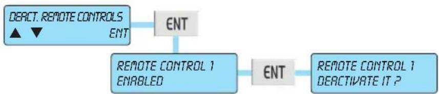
flowchart
graph TD
    A["DEACT. REMOTE CONTROLS ▲ ▼ ENT"] --> B["ENT"]
    B --> C["REMOTE CONTROL 1 ENABLED"]
    C --> D["ENT"]
    D --> E["REMOTE CONTROL 1 DEACTIVATE IT ?"]
4. RFA - CONTROL PANELS ART. 01700 - 01703
Notes for the phone numbers and for the codes enabled for the functions:
- With each alarm communication call, pressing button 4 on your phone deletes any calls to the subsequent phone numbers.
- Pressing button 3 takes you straight into User Telemanagement.
RFA Function - Remote Function Access
a) Call the system from a remote telephone.
b) Wait for the prompt to enter the Code.
c) Enter the digits of the User Code.
d) Once the Code has been recognized, you can access the functions that will be directly invoked by the voice guidance on line.
- Note: The code that allowed access must be enabled to access the functions.
Skipping voice mail or fax
1) Call the system's number: hang up on the first ring of the phone.
2) Call back after 10 s and no later than 30 s.
3) On the first ring, the control panel will respond with the prompt to enter the Code.
4) Continue the procedure following the previous point c).
Table of commands
The commands that can be managed from the access function to the remote functions are:
1. Area management:
- Area status
- Switching ON
- Switching on INT
- Switching on PAR
- Switching OFF
2. Input management:
- Input status
- Cutting off the input
- Cutting in the input
- Resetting the Memory
3. Output management:
- Output status
- Activate the Output
- Deactivate the Output
4. Advanced functions:
- Macro
- Phone Numbers
- Programmable Time Switch
- Date and time
5. Press \* to exit.
6. Press # to listen again.
By-alarm system remote function access
5. BY-ALARM SYSTEM REMOTE FUNCTION ACCESS
This section describes the remote function access features that can be implemented with the By-Alarm system by calling the telephone number paired with the control panel equipped with the voice synthesis module art. 01713 (the number is that of the landline if the PSTN communicator art. 01708 is installed, whereas it is that of the SIM if the GSM module art. 01706 is installed).
To perform remote function access via a phone call, you need to pair the desired USER CODES with the remote function access option type DTMF; when the control panel prompts for the code you can enter the INSTALLER code (which allows only certain types of remote function access) or the USER code previously enabled to access all the types of remote function access.
Following remote function access (by phone or SMS) the keypad will display "Remote Function Access" which can be reset by entering the User code and then resetting the memory.
OPTIONS THAT CAN BE SELECTED DURING REMOTE FUNCTION ACCESS
- AREA MANAGEMENT: enables switching on (ON/INT/PAR) or off (OFF) the desired Areas or requesting their status; this function is allowed only when performing remote function access with a USER code.
- INPUT MANAGEMENT: lets you exclude, include, reset the paired alarms or query the status of the desired input.
- OUTPUT MANAGEMENT: lets you switch on, switch off, or query the status of the desired output.
- ADVANCED FUNCTIONS: lets you control the Macros (start, stop, reset or query the status), check or edit the phone numbers, activate, deactivate, or query the status of the Time Programs and set the Date and Time.
Remote Function Access with INSTALLER Code
When phoning remotely you can enter remote function access by keying in the INSTALLER code.
However there are limited functions, for example it is not possible to apply the "OFF/ON/INT/PAR" command for the Areas, whereas you can edit the phone numbers in the "phone numbers" list and exclude or include the inputs in the event of their malfunctioning.
Remote Function Access with USER Code
- User code digits: you can set 4, 5 and 6-digit codes; for a 4 or 5-digit code, to enter remote function access, enter # after entering the code on your phone.
If the code has been entered correctly you can manage all the features of remote function access.
CALLS TO THE CONTROL PANEL
The wait time between a call to the control panel and the next one is 5 minutes; after making and ending a call, therefore, no more incoming calls will be accepted for the next 5 minutes. The user will hear the ring tone but the control panel will not answer.
The control panel will also not accept calls as long as it is making calls to the numbers in the "Phone numbers" list. Calls are accepted only in the wait time between one attempt and the next one, that is in the time set with the "Pause after second attempt" parameter.
The following example describes the operating logic of the control panel sending calls when there is an alarm event.
-
A call is made or an SMS message is sent to all the numbers in the "Phone numbers" list in the order in which they were programmed and regardless of the set "Retry count".
-
If the calls are not terminated, and the "Retry count" is other than 0, a call is quickly made to all the numbers in the "Phone numbers" list (with no wait times to set) in the order in which they were programmed. If you have selected the "Wait for voice answer" flag, calls are not sent to the numbers that answered on the first attempt.
By-alarm
By-alarm system remote function access
- If the calls are not terminated, and the "Retry Count" is greater than 1, once the first cycle of phone calls just described has ended and after the time set via the "Pause after second attempt" parameter, another call is made to all the numbers in the "Phone numbers" list in the order in which they were programmed; according to the value set for "Retry count" a number of cycles of calls will be made to that number. If you have selected the "Wait for voice answer" flag, calls are not sent to the numbers that answered a previous phone call.
SMS Remote Function Access
- SMS to the control panel: if SMS messages are sent to the control panel while it is carrying out the cycle of calls to the numbers in the "Phone numbers" list, only the first SMS is saved and the command is implemented at the end of the calls.
- User code digits: you can set only 6-digit user codes.
Caution: To use this type of remote function access you need to install the Vimar By-phone app on your smart-phone.
NOTE: If commands are sent remotely, the keypad will display "REMOTE FUNCTION ACCESS"; this will remain displayed until a valid user code is entered.
- Contents
- User activations 2
- Functions and settings 13
- Function tree 15
- RFA control panels art. 01700-01703 25
- By-alarm system remote function access 27
- USER ACTIVATIONS
- Buttons, controls and indicators on the keypad
- Direct warnings on the display
- User activations
- Keypad locking
- Keypad unlocking
- Indicators on display with User Code
- Total switch-on with Code
- Switching off from total switch-on with Code
- Internal or partial switch-on with Code
- Switching off from internal or partial switch-on with Code
- Switching on the control panel in "FAST MODE"
- Switching off the control panel in "FAST MODE"
- Switching on different systems with Code
- Switching off different systems with Code
- Switching on multiple systems in "FAST MODE" (if programmed)
- Switching off multiple systems in "FAST MODE" (if programmed)
- How to activate direct alarm calls
- PANIC:
- FIRE:
- DOCTOR:
- Functions and settings
- FUNCTIONS AND SETTINGS
- With Code associated with a system
- With Code associated with multiple systems
- Primary Menu diagram
- FUNCTION TREE
- Events Memory
- Zone management
- User Management
- Phone numbers
- Operations
- Set Date and Time
- System test
- Function tree
- Consulting the Events Memory
- Resetting alerts
- Exclude zone
- Reinclude zone
- Changing your own User Code
- Changing other codes
- Change phone numbers
- Activate and Deactivate Outputs
- Activate Macro instructions
- Activate and deactivate Programmable Time Switch
- Activate Overtime
- Phone calls
- Walk Test
- Keypad buzzer management
- Activate Relay 1 and Relay 2
- Check Remaining Credit on GSM
- SIM expiry
- Deactivation of Remote Controls
- RFA - CONTROL PANELS ART. 01700 - 01703
- RFA Function - Remote Function Access
- Skipping voice mail or fax
- Table of commands
- Area management:
- Input management:
- Output management:
- Advanced functions:
- Press \* to exit.
- Press # to listen again.
- By-alarm system remote function access
- BY-ALARM SYSTEM REMOTE FUNCTION ACCESS
- OPTIONS THAT CAN BE SELECTED DURING REMOTE FUNCTION ACCESS
- Remote Function Access with INSTALLER Code
- Remote Function Access with USER Code
- CALLS TO THE CONTROL PANEL
- By-alarm
- SMS Remote Function Access
Brand : Vimar
Model : 01705
Category : Alarm