PH6500Ri - Generator Powerhouse - Free user manual and instructions
Find the device manual for free PH6500Ri Powerhouse in PDF.


| Product Type | Digital Inverter Generator |
| Model | PH6500Ri |
| Brand | Powerhouse |
| Rated Power | 6000 W |
| Max Power | 6500 W |
| Rated Voltage | 120 V (selectable 120/240 V) |
| Rated Current | 50 A |
| Frequency | 60 Hz |
| Engine Type | 4-stroke, 1-cylinder, air-cooled, OHV |
| Engine Displacement | 420 cc |
| Engine Horsepower | 11.6 HP |
| Starting System | Electric key and remote |
| Fuel Type | Unleaded gasoline (max 10% ethanol) |
| Fuel Tank Capacity | 5.8 gal (22 L) |
| Oil Capacity | 37.2 fl oz (1.1 L) |
| Recommended Oil | SAE 15W-40 (above 32°F), SAE 0W-40 (below 32°F) |
| DC Output | 12 V, 8.3 A |
| Battery | 12 V, 20 A fuse |
| Run Time at Rated Load | 5.3 hours |
| Run Time at 1/2 Load | 8.4 hours |
| Run Time at 1/4 Load | 12.8 hours |
| Noise Level | 73-78 dB @ 23 ft (7 m) |
| Dimensions (H×W×D) | 29.5 × 28 × 32 in (749 × 711 × 813 mm) |
| Dry Weight (with battery) | 186 lb (84 kg) |
| Tire Pressure (Pneumatic) | 24 PSI |
| Warranty | 2 years or 1000 hours (residential), 1 year or 500 hours (commercial) |
Frequently Asked Questions - PH6500Ri Powerhouse
User questions about PH6500Ri Powerhouse
0 question about this device. Answer the ones you know or ask your own.
Ask a new question about this device
Download the instructions for your Generator in PDF format for free! Find your manual PH6500Ri - Powerhouse and take your electronic device back in hand. On this page are published all the documents necessary for the use of your device. PH6500Ri by Powerhouse.
USER MANUAL PH6500Ri Powerhouse
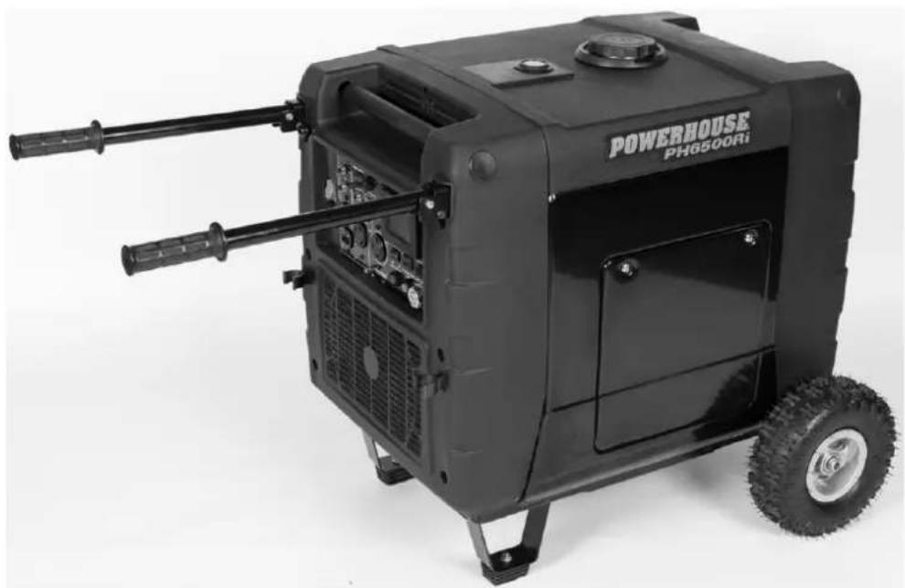
PH6500Ri Digital Inverter Generator
natural_image
Black powertrain device labeled 'POWERHOUSE PH6500Ri' with visible wheels and internal components (no text beyond label)OWNER'S MANUAL
PLEASE READ THIS MANUAL
CAREFULLY BEFORE USING
QUICK START
WARNING
- Use outdoors only. Generators produce carbon monoxide — a poisonous, colorless, odorless gas that can cause death or serious injury.
• Always operate on a level surface. - Keep away from rain, snow or other wet conditions.
- Keep away from smoking materials, sparks, and other sources of combustion when refueling.
Pre-Operation
- Use the embedded handles to move the generator on flat terrain. Use the folding handles to move the generator on rough or uneven terrain. Refer to the Using the Handles section for more information.
- Add oil by removing the maintenance door and inspecting the dipstick. Fill the oil reservoir with 37.2 fl oz (1.1 L) of oil, or to the full mark on the dipstick. Use appropriate grade, high-detergent, premium quality, 4-stroke engine oil (synthetic or conventional). Use SAE 15W-40 viscosity oil unless operating at ambient temperatures below 32^ (0°C). For temperatures below 32^ , use SAE 0W-40 viscosity oil. Synthetic oil is also recommended for temperatures below 32^ . Refer to the Operating at extreme temperatures section for more information.
- Remove the maintenance door and connect the quick connect cable to the battery wiring harness. Refer to the Connecting the battery section for more information.

- Replace the maintenance door.
- Connect an external battery charger (such as the TC2-P Plug-In Trickle Charger, part number 19674) to the DC receptacle in the "Battery Charger" section of the control panel.
NOTE
- The TC2-P Battery Charger also includes an alligator clip cable that plugs into the T-style male DC connector of the charger, allowing you to connect the clips to the terminals for batteries powering other equipment. For POWERHOUSE® generators, for ease of use, it is suggested that you connect the T-style male plug to the DC receptacle on the control panel, rather than attempting to charge the generator battery directly.

- Charge the battery for 3 hours or until it is fully charged. After the battery is fully charged, disconnect the battery charger.

NOTE
- If you are using the TC2-P Plug-In Trickle Charger, the status indicator will go from red to green when the battery is fully charged.
- Carefully add regular unleaded automotive gasoline up to the shoulder of the fuel strainer. To avoid spilling fuel, use care to not fill too quickly or over fill. Avoid getting dirt, dust, or water in the fuel tank. Do not use a blend that contains more than 10% ethanol. Do not use gasoline containing methanol. An octane rating of 87 or higher is recommended.

CAUTION
- Do not add 2-Stroke oil to your fuel. Doing so will void your warranty.

NOTE
- It is recommended that you use a fuel stabilizer, such as STA-BIL®, to help prevent fuel oxidation (breakdown) and the formation of gum and varnish, and to inhibit corrosion in the fuel system and carburetor.
Operation
- Ensure that no loads have been connected to the AC receptacles.
- Open the fuel valve.
- Start the engine in one of the following ways.
A. Electric Start:
- Insert the ignition key, and turn it all the way to the START position. Hold key at this position until the engine is running or for a maximum of 10 seconds. Release and repeat if necessary.
B. Remote Start:
- Turn the remote switch to the "ON" position.
- Push the start button on the remote twice and hold until the engine has started or for a maximum of 10 seconds. Release and repeat if necessary.
-
Always place the remote switch on the control panel in the "OFF" position when not in use to prevent running down the battery.
-
The digital display will illuminate and display data when the generator is ready for use. Before connecting any loads, ground the generator with a length of heavy cable, connecting the generator's grounding terminal to an external ground source.
- Use the voltage selector switch to select either 120V-only operation or 120V/240V operation. For the location of the voltage selector switch, refer to the PH6500Ri Control Panel section.

WARNING
- Do not use the switch while a load is connected. Switching the voltage while a load is connected may burn out the voltage selector switch.
- Make sure that all appliances to be connected have been switched off and are in good working order. Confirm that the electrical rating does not exceed that of the generator.
- Connect your appliances to the appropriate receptacle on the generator's panel.
- To minimize fuel consumption and noise, push the economy switch to the "ON" position. This setting regulates the engine's speed so that it matches the needs of the connected loads. Do not use the economy setting if you are connecting items with electric motors that have a high amperage draw during startup or with appliances that cycle on and off rapidly.
Shutdown

NOTE
- In an emergency, pushing the STOP button on the control panel will automatically stop the engine without the ignition key or remote, with or without a load. However, continually stopping the generator without disconnecting all loads can cause damage to the generator or appliances.
-
If you start your unit with the key in the ignition, shut it down with the key in the ignition. If you start your unit with the remote fob, shut it down with the remote fob. Regardless of the way you start the generator, the red STOP button will shut it down.
-
Turn off all connected appliances and disconnect from the generator.
- Use one of the following methods to turn off the generator.
A. If the remote switch is "OFF": Turn the ignition key to the "OFF" position.
B. If the remote switch is "ON": Push and hold the stop button on the remote or on the panel.

CAUTION
- Make sure the remote switch is off. If the remote switch remains on for extended periods of time, it will drain the battery. If the remote switch is on after the generator has been shut down, the remote indicator light will flash to remind you to turn it off.
- Turn the fuel valve off.
FCC INFORMATION

me: Coast Distribution Inc.
H6500PRi
This device complies with Part 15 of the FCC Rules. Operation is subject to the following two conditions: (1) this device may not cause harmful interference, and (2) this device must accept any interference received, including interference that may cause undesired operation.
Pursuant to FCC regulations, do not to make any changes or modifications to the remote control transmitter or receiver that are not expressly approved by Coast Distribution Inc. Doing so could void your authority to operate the equipment and will void the warranty.
Notice
This equipment has been tested and found to comply with the limits for a Class B digital device, pursuant to Part 15 of the FCC Rules. These limits are designed to provide reasonable protection against harmful interference in a residential installation. This equipment generates uses and can radiate radio frequency energy and, if not installed and used in accordance with the instructions, may cause harmful interference to radio communications. However, there is no guarantee that interference will not occur in a particular installation.
If this equipment does cause harmful interference to radio or television reception, which can be determined by turning the equipment off and on, the user is encouraged to try to correct the interference by one or more of the following measures:
- Reorient or relocate the receiving antenna.
- Increase the separation between the equipment and receiver.
- Connect the equipment into an outlet on a circuit different from that to which the receiver is connected.
- Consult the dealer or an experienced radio/TV technician for help.
PREFACE
Thank you for purchasing a POWERHOUSE® generator.
This manual covers the operation and maintenance of the POWERHOUSE® generator model PH6500Ri.
All information in this publication is based on the latest product information available at the time of approval for printing.
We reserve the right to make changes at any time without notice and without incurring any obligation.
No part of this publication may be reproduced without written permission.
This manual should be considered a permanent part of the generator and should remain with it if it is resold.
Pay special attention to statements preceded by the following words:



- Indicates a strong possibility of severe personal injury or death if instructions are not followed.
- Indicates a possibility of personal injury or equipment damage if instructions are not followed.
• Gives helpful information.
If you have a problem with this generator, do not return it to the store where you purchased it. For warranty support call 877-544-4449 from 8am to 6pm ET, email us at warranty@powerhouse-products.com or send a fax to 800-263-0280.

- Failure to properly follow these precautions can result in property damage, serious injury, or DEATH!
- Read all labels and the owner's manual before operating this generator.
- Generators produce carbon monoxide — a poisonous, colorless, odorless gas that can cause death or serious injury.
- Indoor use of a generator can kill quickly. Generators should be used outdoors only.
- Generators should only be used outdoors, away from garages and open windows, but protected from rain and snow.
- Check for spilled fuel or leaks. Clean and/or repair before use.
• Always stop engine before refueling. Wait 5 minutes before restarting. - Keep any source of ignition away from fuel tank, at all times.
- The portable generator is not meant to be used as a permanent back-up power system for the home. A permanently installed stationary generator is designed to be safely used for this specific purpose.
- Our generators are designed to give safe and dependable service if operated according to instructions. Read and understand the owner's manual before operating the generator. Failure to do so could result in personal injury or equipment damage.
TABLE OF CONTENTS
PH6500Ri Digital Inverter Generator....1
QUICK START 2
Pre-Operation 2
Operation 3
Shutdown 4
FCC INFORMATION......4
Notice 4
PREFACE 5
-
SAFETY INSTRUCTIONS....8
-
COMPONENT IDENTIFICATION....9
2.1 PH6500Ri Generator 9
2.2 PH6500Ri Control Panel....10
2.3 Serial number and bar code identification and location.... 11
-
USING THE HANDLES 12
-
PRE-OPERATION CHECK....13
4.1 Check the Engine Oil Level 13
4.2 Check the fuel level....14
4.3 Check the air cleaner....15
4.4 Connecting the battery....16
4.5 Battery removal and replacement....17
- OPERATING INSTRUCTIONS....18
5.1 Starting the engine....18
5.2 Starting procedure using the Ignition Key....18
5.3 Starting procedure using the remote function....19
5.4 High Altitudes....19
5.5 Operating at extreme temperatures....19
5.6 Generator use....20
5.7 120V/240V Operation ......21
5.8 Digital display....22
5.9 AC application....23
5.10 Overload conditions 25
5.11 Low voltage protection 26
5.12 DC application....27
5.13 Low oil alarm system 29
5.14 Economy switch....30
5.15 Stopping the engine....31
5.16 Air conditioner operation 32
- MAINTENANCE....33
6.1 Emission Control System....33
6.2 Maintenance Schedule 35
6.3 Changing oil....36
6.4 Air cleaner service....37
6.5 Spark plug service 38
6.6 Spark arrester maintenance ....39
- TRANSPORTING & STORAGE 40
7.1 Transporting the Generator....40
7.2 Short term storage of the Generator....40
7.3 Infrequent use....41
7.4 Exercising the Generator 41
- TROUBLESHOOTING....42
8.1 Engine will not start....42
8.2 Engine will not crank with the key or remote start 43
8.3 Appliance does not operate 43
8.4 No output at the DC receptacle 44
8.5 Digital display is illuminated but there is no data....44
-
SPECIFICATIONS 45
-
WARRANTY AND CONSUMER INFORMATION......47
CALIFORNIA EMISSIONS CONTROL WARRANTY STATEMENT 48
EMISSION CONTROL SYSTEM WARRANTY 49
- APPENDIX A - EMISSION CONTROL SYSTEM....50
- APPENDIX B - SAFETY AND CHARGING INSTRUCTIONS ....51
1. SAFETY INSTRUCTIONS


- This generator is designed to give safe and dependable service if operated according to instructions.
- Read and understand this owner's manual before operating the generator. Failure to do so could result in personal injury or equipment damage.


- Exhaust gas contains poisonous carbon monoxide. Never run the generator in an enclosed area.
- Be sure to provide adequate ventilation.

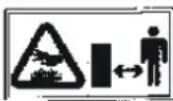
- The muffler becomes very hot during operation and remains hot for several minutes after stopping the engine.
- Be careful not to touch the muffler while it is hot.
- Let the engine cool before storing the generator indoors.
To ensure safe operation

- Gasoline is extremely flammable and explosive under certain conditions. Refuel in a well ventilated area with the engine stopped.
- Keep away from cigarette smoke and sparks when refueling the generator.
- Wipe up spilled gasoline at once.


- This generator can be used as a standby power supply, but it is very important to get a qualified electrician to set it up. If the unit is not properly set up, severe property damage and/or severe personal injury or death may result.
- Never connect this generator to an automatic transfer switch (ATS). Severe damage to the generator will occur.

- To avoid accidents or equipment damage, always make a pre-operation inspection before you start the engine.
- Place the generator at least 3 ft (1 m) away from buildings or other equipment during operation.
- Operate the generator on a level surface. If the generator is tilted, fuel spillage may result.
- Know how to stop the generator quickly and understand operation of all controls. Never permit anyone to operate the generator without proper instructions.
- Keep children and pets away from the generator when it is in operation.
- Keep away from moving parts while the generator is running.
- Generators are a potential source of electrical shocks when misused; do not operate with wet hands.
- Do not operate the generator in rain or snow and do not let it get wet.
- Do not install this generator inside a compartment. Doing so may lead to overheating and consequently, fire. It may also lead to death by asphyxiation.
- Do not modify the enclosure of this generator.
2. COMPONENT IDENTIFICATION
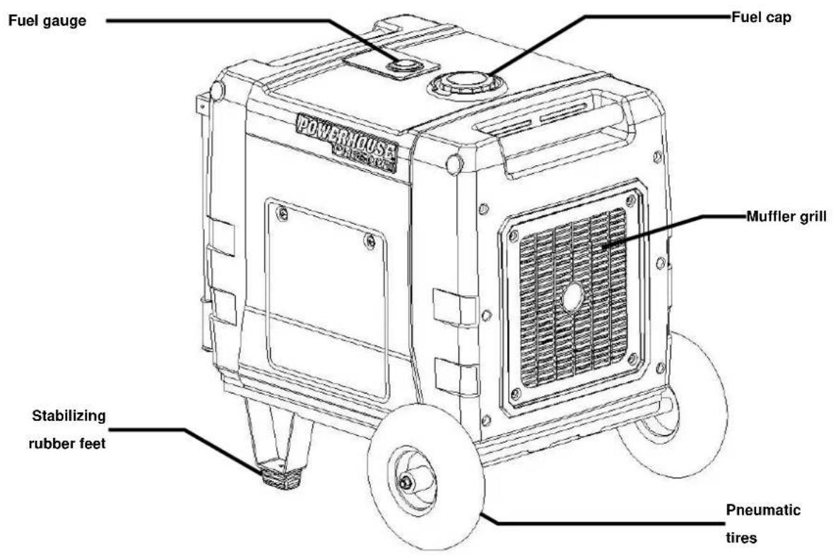
2.1 PH6500Ri Generator

2.2 PH6500Ri Control Panel

| A | Remote indicator |
| B | 120V 30 A circuit breaker for L5-30R lock twist receptacle |
| C | Remote switch |
| D | L1 25 A circuit breaker for L14-30R lock twist receptacle |
| E | Voltage selector switch |
| F | L2 25 A circuit breaker for L14-30R lock twist receptacle |
| G | Low oil indicator |
| H | Overload L1 indicator |
| I | Overload L2 indicator |
| J | Digital display |
| K | 12 V DC – 8.3 A battery charge receptacle (internal and external) |
| L | DC circuit breaker |
| M | Ignition switch |
| N | Stop button (Red) |
| O | Overload reset button (Green) |
| P | Economy switch |
| Q | Grounding terminal |
| R | L14-30R lock twist receptacle (240VAC – 50 A, 120V/L1 and 120V/L2) |
| S | L5-30R lock twist receptacle (120VAC – 30 A) |
| T | 5-20R split duplex receptacle (120VAC – 20 A) |
| U | 120VAC – 20 A circuit breakers for 5-20R split duplex receptacle |
2.3 Serial number and bar code identification and location
The generator bar code number and the engine serial number identify your particular unit and are necessary when ordering parts and accessories. These two numbers are used by your dealer and The Coast Distribution System, Inc. for warranty administration and must be supplied before any work can be done.

The engine serial number can be found stamped on the engine block near the oil dipstick. It is visible when the maintenance door is removed.
BCN # 100122377055322
The BCN number label is found in two locations:
- On the side of the generator toward the muffler grill, close to the bottom.
- On the back of this owner's manual.
You can also find the BCN number on the foil label on the shipping carton.
Please record this information below and keep this manual in a safe place along with the bill of sale.
Engine Serial Number
Bar Code Number (BCN) ____
Date of Purchase
Name of Selling Dealership ____
Please go to www.powerhouse-products.com/register and register your unit today. Online registration will be accepted as proof of purchase. Online registration will make sure you are protected in the event you have lost your receipt, and will significantly speed the process in the event warranty service is necessary.
For warranty assistance:
Phone: 877-544-4449
Fax: 800-263-0280
E-mail: warranty@powerhouse-products.com
3. USING THE HANDLES
WARNING
- Using the handles without locking them properly in place can damage the handle brackets.
This generator includes a total of four (4) handles. Two of the handles are fixed into the top of the cabinet on the ends (one handle over the control panel and one handle over the muffler grill). These handles are good for rolling the generator along even, smooth terrain or for tie-down during transportation. There are also two folding handles for ease in moving the generator along rough or uneven terrain. The handles fold down when not in use, locked in place on either side of the control panel by retaining clips. The handles extend upward parallel with the top of the unit and lock in place so that the generator may be moved wheelbarrow-style with stability.
Each folding handle has a locking mechanism at the handle bracket consisting of a spring-secured locking rod with a round, black lock knob on the end of it. To lock or unlock the folding handle in its extended position, push the lock knob in to unlock the handle so that the handle can slide forward or backward freely within the handle bracket.
CAUTION
- For safety reasons, it is better to shut the generator down before moving it. You should also unplug all cords connected to the generator to prevent a tripping hazard and/or damage to the cords or receptacles.
To extend and lock the folding handles:
- Pull each handle free from its retaining clip and rotate it upward until it is fully extended.
- Push the lock knob in and push the handle inward (toward the generator) so that the handle can slide to a fully seated position.
- Release the lock knob, securing the handle in the handle bracket.
- Repeat to extend and lock the other handle.
To unlock the extended handles and stow them properly:
- Push the lock knob in and pull the handle outward (away from the generator).
- Release the plastic lock knob.
- Rotate each handle downward and snap it into its retaining clip.


4. PRE-OPERATION CHECK

- Be sure to check the generator on a level surface with the engine stopped.
4.1 Check the Engine Oil Level

- Do not use non-detergent oil or 2-stroke engine oil. It will void the warranty and will shorten the engine's service life.
- Use a high-detergent, premium quality 4-stroke engine oil, certified to meet or exceed U.S. automobile manufacturer's requirements for API Service Classification SG/SF. Synthetic oil is approved for use in POWERHOUSE® generators, and is recommended for operating the generator in temperatures below 32°F.
- Change the oil in a new engine within the first 4 to 6 hours of operation to clean manufacturing debris and contamination.
-
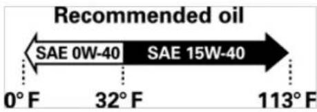
Use SAE 15W-40 viscosity oil unless operating at ambient temperatures below 32°F (0°C). For temperatures below 32°F, use SAE 0W-40 viscosity oil. Refer to the Operating at extreme temperatures section for more information.
-
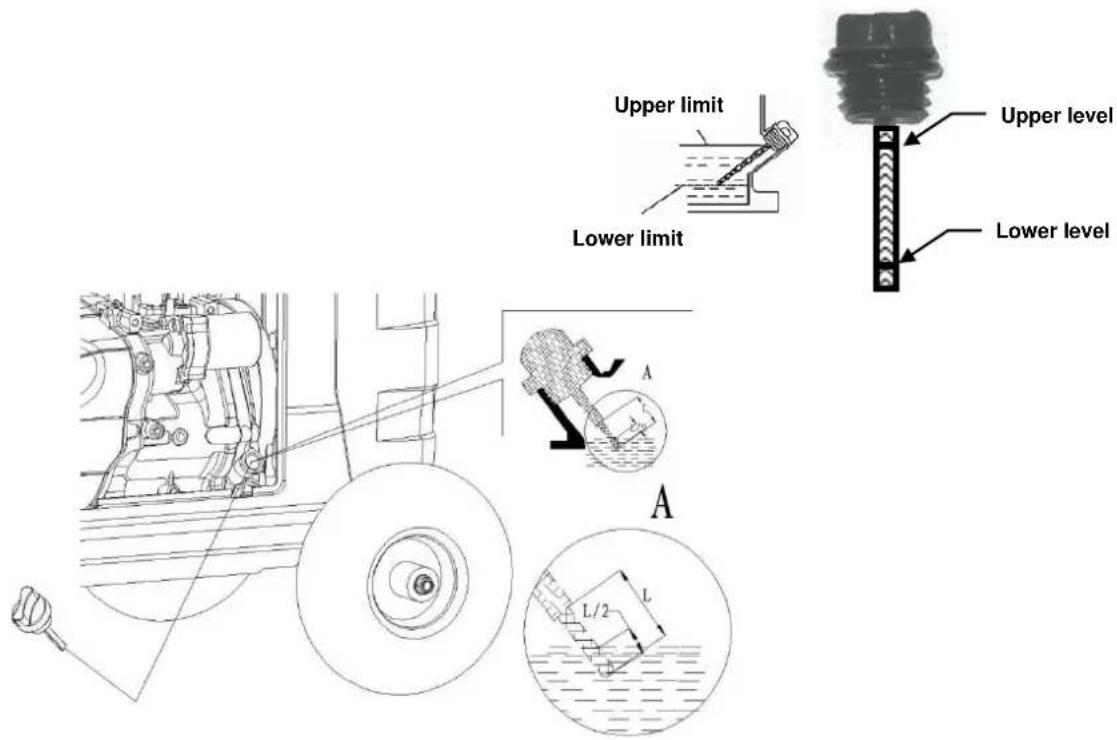
Loosen the maintenance door screws and remove the cover.
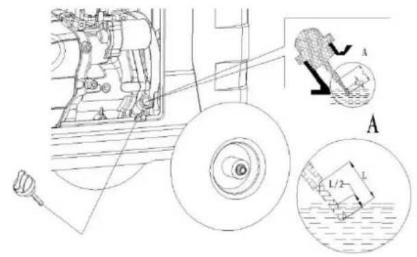
- Remove the dipstick, wipe it with a clean rag and reinsert it into the filler neck. You do not have to screw the dipstick down completely.
- Remove the dipstick again and check the oil level.
- If the oil level is at or below the lower level on the dipstick, refill with the recommended oil up to the top of the upper level marking. Do not overfill.
- Reinsert the dipstick and be sure to screw it down until it is tight.
- Reinstall the maintenance door and tighten the screws securely.

- Running the engine with insufficient oil can cause serious engine damage.
- The Low oil alarm system will automatically stop the engine before the oil level falls below a safe limit. However, to avoid the inconvenience of an unexpected shutdown, it is still advisable to visually inspect the oil level regularly.
Engine oil capacity: 37.2 fl oz. (2.33 pt) / 1.1 L
4.2 Check the fuel level
You can check the fuel level two ways:
- Check the mechanical fuel gauge located on top of the generator
- Check the fuel reading on the digital display, which provides a series of bars indicating fuel level
For more information on the digital display, including the fuel reading, refer to the Digital display section.
Use automotive unleaded regular gasoline only.
- If the fuel level is low, refill to the shoulder of the fuel strainer.
- Never use an oil/gasoline mixture or dirty gasoline.
- Avoid getting dirt, dust or water in the fuel tank.
- After refueling, tighten the fuel filler cap securely.

NOTE
- It is recommended that you use a fuel stabilizer, such as STA-BIL®, to help prevent fuel oxidation (breakdown) and the formation of gum and varnish, and to inhibit corrosion in the fuel system and carburetor.

WARNING
• Gasoline is extremely flammable and is explosive under certain conditions.
- Refuel in a well-ventilated area with the engine stopped. Keep all smoking materials, sparks, and any other source of combustion away from the generator during refueling.
- Do not overfill the fuel tank (there should be no fuel above the upper limit mark). After refueling, make sure the tank cap is closed properly and securely.
- Be careful not to spill fuel when refueling. Spilled fuel or fuel vapor may ignite. If any fuel is spilled, make sure the area is dry before starting the engine.
- Avoid repeated or prolonged contact of fuel with skin or breathing of fuel vapor. KEEP OUT OF REACH OF CHILDREN.
Fuel tank capacity: 5.8 gal (22 L)

Gasoline containing alternate fuels
Do not use a blend that contains more than 10% ethanol. Do not use gasoline containing methanol. Octane rating of 87 or higher is recommended.

NOTE
- Fuel system damage or engine performance problems resulting from the use of fuels that contain an improper alcohol blend, or by adding oil to the fuel, are not covered under warranty.
- Before buying fuel from an unfamiliar station, determine if the fuel contains ethanol and if it does, confirm the type and percentage of ethanol used. If you notice any undesirable operating symptoms while using a gasoline that contains ethanol, or one that you think contains ethanol, replace it with a gasoline that you know has the proper blend.
4.3 Check the air cleaner
-
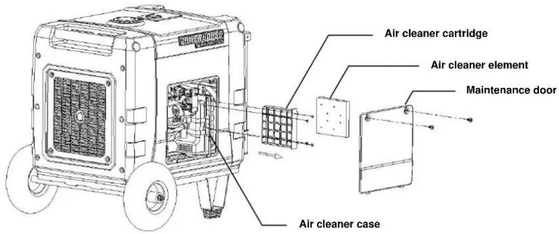
Loosen the cover screws and remove the maintenance door.
-
Remove the air cleaner cartridge retaining screws. Remove the air cleaner cartridge and check the element. Clean or replace the element if necessary.
-
Replace the air cleaner element and cover. Tighten the screw securely.
-
Replace the maintenance door and tighten the screw securely.
CAUTION
- Never run the engine without the air cleaner element. Rapid engine wear will result from contaminants, such as dust and dirt, being drawn through the carburetor, into the engine.
4.4 Connecting the battery
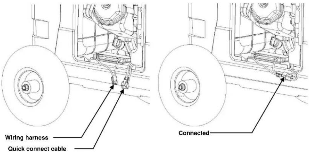
This generator ships with the internal battery disconnected, meaning you will have to connect the battery before you begin using the generator.
- Loosen the cover screws and remove the maintenance door.
- Connect the quick connect cable to the battery wiring harness.
- Replace the maintenance door and tighten the cover screws.

- Due to the nature of lead acid batteries, it may be necessary to charge the battery before using the generator the first time, or after long term storage. It is recommended to connect a battery charger (for example, the TC2-P Plug-In Trickle Charger) to the DC receptacle in the "Battery Charger" section of the control panel to charge the battery, as described in the Pre-Operation section of this manual.
4.5 Battery removal and replacement
Removal
- To remove the battery for maintenance or replacement, loosen the cover screws and remove the side maintenance door.
- Unplug the quick connect cable from the wiring harness, remove the battery clamp and lift the battery out.
- Replace the maintenance door and tighten the door screws.
Replacement
- To replace the battery, loosen the cover screws and remove the side maintenance door.
- Connect the quick connect cable to the wiring harness, seat the battery and the battery clamp, then tighten the screw for the battery clamp.
- Replace the maintenance door and tighten the door screws.
5. OPERATING INSTRUCTIONS
5.1 Starting the engine

- The unit can be started by either the ignition key or remote. When the unit is started with the ignition key, it can be shut down by the ignition key or the STOP button on the control panel; but NOT by the remote. When the unit is started by the remote, it can be shut down by the remote. If you want to shut down the unit with the ignition key when the unit has been started by remote, you will need to turn the remote control switch on the control panel to the "OFF" position before you can shut off the unit with the ignition key. The unit can always be shut down by the STOP button on the control panel regardless of how you start the unit.
- When starting the generator after adding fuel for the first time or after long term storage, or after running out of fuel, turn the fuel valve to the "ON" position, then wait for 10 to 20 seconds before starting the engine.
- Before starting the engine, disconnect any load from the AC receptacles.
5.2 Starting procedure using the Ignition Key
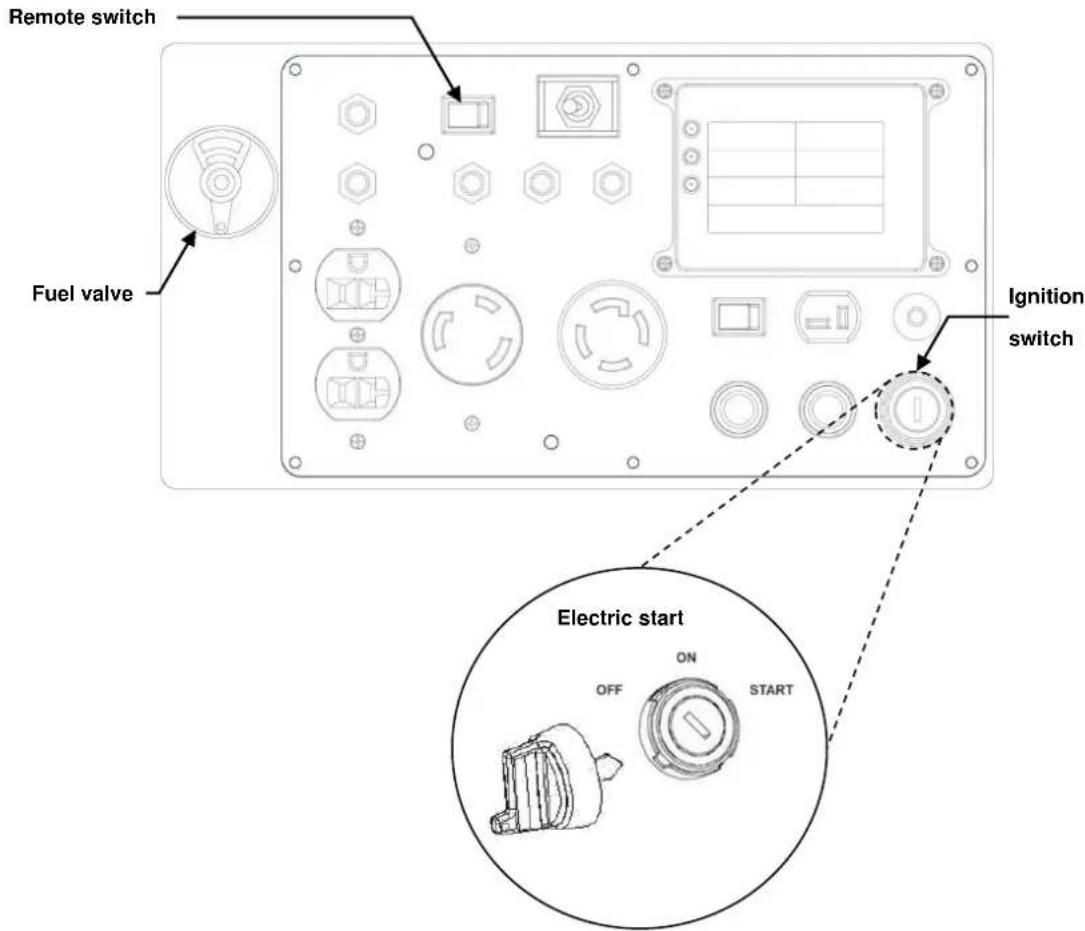
- Turn the fuel valve to the "ON" position.
- Move the remote selector switch on the control panel to the "OFF" position.
- Turn the ignition switch to the "START" position until the engine has started. Do not operate the starter for more than 10 seconds. Repeat if necessary.
5.3 Starting procedure using the remote function
- Turn the fuel valve lever to the "ON" position.
- Move the remote selector switch on the control panel to the "ON" position.
- Push the start button on the remote twice and hold until the engine has started. Do not operate the starter for more than 10 seconds. Repeat if necessary.


NOTE
• The maximum operating range is 75' based on a clear line of site.
- Always place the remote switch on the control panel in the "OFF" position when not in use for an extended period of time, to prevent running down the battery. The remote indicator light will illuminate and flash if the remote switch is on while the generator is not running.
5.4 High Altitudes
At high altitude, the standard carburetor air-fuel mixture will be excessively rich, performance will decrease, and fuel consumption will increase. Horsepower will decrease approximately 3.5% for each 1000 foot (305 meters) increase in altitude.
5.5 Operating at extreme temperatures
High temperature adversely affects generator operation. Generator performance will decrease 1% for each 10^ F ( 5.5^ C) increase in temperature above 85^ F ( 29^ C). The normal operating range of this generator is 0^ to 113^ F (- 18^ to 45^ C). Although the generator can operate at 0^ F (- 18^ C) it will be necessary to use a lower viscosity engine oil such as SAE 0W-40. Synthetic oil is recommended for temperatures below 32^ F. Even with cold weather oils, the engine will be more difficult to start.

NOTE
- In very cold weather the engine will actually take longer than normal to warm up because the oil is thinner and there is less internal friction throughout the warm up period. Once the engine reaches operating temperature 0W-40 oil is no thinner than straight 40W.

CAUTION
- Do not operate the generator when the ambient temperature is below 0^ (-18°C). - Do not operate the generator when the ambient temperature is above 113^ (45°C).
(-18°C)
(0°C)
(45°C)
5.6 Generator use
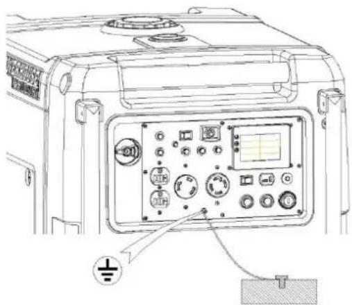
Be sure to ground the generator when loads are connected.
NOTE
WARNING
- BREAK-IN PERIOD: For maximum performance, run your new generator at no more than 50% of the rated load of the generator for 4 hours before you apply a full load for the first time.
- To prevent electrical shock from faulty appliances, the generator should be grounded. Connect a length of heavy cable between the generator's grounding terminal and an external ground source.
- Connections for standby power to a building's electrical system must be made by a qualified electrician and must comply with all applicable laws and electrical codes. Improper connections can allow electrical current from the generator to back feed into the utility lines. Such back feed may electrocute utility company workers or others who contact the lines during a power outage. When utility power is restored the generator may explode, burn, or cause fires in the building's electrical system.
- Do not connect the generator to an automatic transfer device. Severe damage to the inverter module may result.
- Do not attempt to connect generators in parallel.
- Indoor use of a generator can kill quickly. Generators should be used outdoors only.
CAUTION
• The total wattage of all appliances connected must be considered.
- Do not exceed the current limit specified for any one receptacle.
- Do not connect the generator to a household circuit. This could cause damage to the generator or to electrical appliances in the house.
- Do not modify or use the generator for purposes other than its intended use.
- Do not connect an extension to the exhaust pipe.
- When an extension cord is required, be sure to use a rubber sheathed flexible cord. Also be sure to use the proper size and length cord.
- 16 Gauge Cords - a 16 gauge cord between 0 and 100 feet long will safely handle tool and appliance loads up to 10 amps.
- 14 Gauge Cords - a 14 gauge cord between 0 and 50 feet long will safely handle tool and appliance loads between 10 and 15 amps.
- 12 Gauge Cords - a 12 gauge cord between 50 and 100 feet will safely handle tool and appliance loads between 10 and 15 amps.
- Keep the generator away from other electric cables or wires such as commercial power supply lines.
NOTE
- The DC receptacle (in the "Battery Charge" section of the control panel) can be used while the AC power is in use. If you use both at the same time, be sure not to exceed the total power for AC and DC.
- Most appliance motors require more than their rated wattage for start-up.
5.7 120V/240V Operation
This generator provides output at 120V or 240V through the use of the voltage selector switch. When the voltage selector switch is set for 120V-only mode (toggle switch is set to the left), you can plug appliances into the 5-20R split duplex receptacle or the L5-30R twist lock receptacle. In this mode, the 240V L14-30R lock twist receptacle will not supply voltage from either the L1 or L2 circuits. When the voltage selector switch is set for 120V/240V operation (toggle switch is set to the right), the L14-30R twist lock receptacle supplies 240V through two 120V circuits (L1 and L2). You cannot use the L14-30R lock twist receptacle in 120V-only mode. Conversely, you cannot use the 5-20R split duplex receptacle or the L5-30R lock twist receptacle in 120V/240V mode.
The generator can be running when you change the setting on the voltage selector switch.
WARNING
- Do not use the switch while a load is connected. Switching the voltage while a load is connected may burn out the voltage selector switch.
To change the voltage selector switch:
- Disconnect all loads from the generator.
- Set the voltage selector switch to the left for 120V-only operation or to the right for 120V/240V operation.
- Allow a minute for the voltage to normalize.
- Connect the loads one by one, powering up each and allowing a moment for the generator to adjust to each load.
NOTE
- You will need adapters to connect RV power cords to the receptacles on the control panel of this generator. To use the 30A L5-30R receptacle on the generator, you will need an adapter that connects the standard TT-30 30A RV plug to the L5-30R receptacle. To use the L14-30R receptacle on the generator, you will need an adapter that connects the standard 14-50P 50A RV plug to the L14-30R receptacle. You may need a splitter to use only one 120V line from the 240V receptacle, or to use the L1 and L2 lines separately.

5.8 Digital display
This generator is equipped with an LCD digital display that provides continuously-updated status information for the following parameters:
• Voltage – Current voltage supplied (120V/240V)
- Amperage for the L1 and L2 supply lines (for more information on the L1 and L2 supply lines, refer to the 120V/240V Operation section)
- Wattage (power output) for the L1 and L2 supply lines
- Fuel level (bar reading)
- Run time – Total generator run time since first start (in hours)

• The digital display will not illuminate unless the generator is started.
- It is normal for the run time indicator to have 1-2 hours on the meter from the factory for testing and quality assurance inspections.

The digital display will illuminate within a few seconds of the generator starting, and will initially display data from the last run of the generator. Within a few seconds of illumination, the display will begin to show new data, and at that point the generator is ready to supply power.
5.9 AC application
AC power is supplied through two 120V circuits in this generator. The first circuit is called L1 (for "Line 1") and it provides current to the 20A 5-20R split duplex receptacle, the 30A L5-30R receptacle, and the "L1" line of the 50A V L14-30R receptacle. The second circuit is called L2 (for "Line 2"), and it only supplies current to the "L2" line of the 50A L14-30R receptacle. The use of these two circuits is determined by the voltage selector switch. When the voltage selector switch is set for 120V-only operation (to the left), only the L1 circuit is active. When the voltage selector switch is set for 120V/240V operation (to the right), the L2 circuit is activated and the L1 circuit only powers the L1 line of the 50A L14-30R receptacle.
If the generator is running, an appliance is plugged into a receptacle on the generator and turned on, and there is no power being supplied to that appliance through the receptacle, check the breaker for that receptacle. If a breaker has tripped, reset it by pressing the appropriate breaker button. The control panel shown below has lines printed on it indicating which breaker goes with which receptacle. For example, in the following image the 20A breaker in the top left corner has a line leading to the top 5-20R receptacle, which is the receptacle that breaker protects. The 30A breaker is used with the L5-30R receptacle directly beneath it. The 25A breakers protect each 120V line of the L14-30R receptacle, with the breaker on the left protecting L1 and the breaker on the right protecting L2. Each breaker has a button next to it to reset the breaker if it trips.

The digital display panel also has three LEDs on the digital display panel. These are the Low oil, L1 overload, and L2 overload indicators. The low oil indicator will illuminate if the generator is running low on oil and needs oil added. The L1 overload indicator will blink if the inverter is pushed into an overload condition for the L1 120v circuit. The L2 overload indicator will blink if the inverter is pushed into an overload condition for the L2 120v circuit. For more information on overload conditions, including how to resolve them, refer to the Overload conditions section. If an overload occurs, power will be automatically cut by the inverter for that circuit.

natural_image
Technical diagram of an electronic device panel with various components and a zoomed-in inset showing internal structure (no text or labels)Low oil indicator
L1 overload indicator
L2 overload indicator
Digital display: The illuminated digital display returning data indicates normal operating conditions.
When connecting appliances, be aware of the electrical requirements of each appliance, and how much current will be available through each generator receptacle. For example, the L5-30R connector will conduct up to 30 amps. Connecting a combination of appliances that draw more than 30 amps total will overload the circuit. In that case you would connect those appliances to a combination of receptacles, based on the amperage required for each appliance.
You should also consider the overall output of the generator. The rated wattage (power) for this generator is 6000W, and the maximum wattage peaks at 6500W. When the voltage selector switch is set to 120V/240V operation (to the right), you can only use the L14-30R receptacle, which provides two (2) 120V lines, each capable of conducting up to 25 amps. This is ideal for running two air conditioners (refer to the Air conditioner operation section for more information) in an RV, and certain other appliances within the RV that will not push the cumulative current draw over 50 amps. If the voltage selector switch is set for 120V-only operation (to the left), you may use a combination of the 5-20R split duplex receptacle and the L5-30R receptacle, but not the L14-30R receptacle. On the three available circuits you can connect a variety of appliances at the same time, but the cumulative power consumption should not exceed 6000W (or 50 amps) across all three receptacles.
To use the AC generator receptacles:
- Start the engine and make sure the digital display begins returning data.
- Select a voltage to use by setting the voltage selector switch to the left (120V-only) or right (120V/240V) operation.
- Confirm that the appliance to be used is switched off before plugging into the control panel.
- Begin to plug in appliances, or connect the generator to your RV through an adapter.
- Power on your appliances, allowing time for each voltage load to normalize before powering on the next.
- Monitor the overload indicators and breakers while powering on your appliances.

- Be sure that all appliances are in good working order before connecting them to the generator. If an appliance begins to operate abnormally, becomes sluggish, or stops suddenly, turn off the generator engine switch immediately. Disconnect the appliance and examine it for signs of malfunction.
5.10 Overload conditions
If the generator is overloaded (in excess of 6.5KW), or if there is a short in the connected appliance, the digital display will remain illuminated, but will display zeroes for some values, such as wattage and amperage. Either the L1 or L2 overload indicators (red) will blink and the inverter will shut off current to the connected appliance.
When the voltage selector switch is set for 120V only mode, the L1 overload indicator blinks when there is an overload condition on the 5-20R split duplex receptacle or the L5-30R lock twist receptacle. When the voltage selector switch is set to 120V/240V mode, the L1 overload indicator will only blink if there is an overload condition on the L1 120V line on the L14-30R connector. The L2 overload indicator will only blink if there is an overload condition on the L2 120V supply on the L14-30R connector.

CAUTION
- Substantial overloading that continuously illuminates an overload light (red) may damage the generator. Marginal overloading that temporarily illuminates an overload light (red) may shorten the service life of the generator.
If one or both of the overload indicators blink:
- Remove all electrical loads from the generator and investigate and correct the cause of the overload.
- To reset the overload condition (red light blinking), press the (green) overload reset button or stop and restart the generator. The digital display should be illuminated and displaying new data within 10 seconds.

NOTE
- Before connecting or reconnecting an appliance to the generator, check that it is in good order, and that its electrical rating does not exceed that of the generator.
- When an electric motor is started, an overload indicator light (red) may go on momentarily while the digital display continues to return non-zero data. This is not a problem as long as the overload light only flickers on briefly.

Digital display: The digital display illuminated and returning data indicates normal operating conditions.
Overload L1: The red L1 overload light illuminates when the L1 120 V supply is overloaded or has a short circuit.
Overload L2: The red L2 overload light illuminates when the L2 120V supply is overloaded or has a short circuit.
Overload reset button (green)
5.11 Low voltage protection
This generator is equipped with a shutdown feature to help protect your appliances from low voltages caused by excessive inductive loads. An example of an excessive inductive load would be an air conditioner that is connected to the generator with a start-up current that, when added to other existing loads, is beyond the capacity of the generator. This can also occur if an oversized air conditioner is connected. Air conditioners and other products with motors draw a lot of current during start-up. If the startup period is long enough, the voltage can drop to levels that are unsafe for your appliances before the excessive current draw will trigger an overload condition. To avoid this, the low voltage protection feature activates.
• The engine will shut down
- The digital display will show Err1 in the voltage field
If the generator shuts down due to low voltage protection, complete the following steps to restore power:
- Disconnect all loads from the generator.
- Ensure that the total power requirements for all of your appliances can be met by the generator, with special attention to surge power ratings. The total surge power requirements cannot exceed 6500 W. The continuous use power requirements should not exceed 6000 W.
- Restart the engine.
- Reconnect the loads one by one, starting with the loads that have the greatest current requirements.

- Allow time for the generator to stabilize the voltage for each load before applying the next load.
- It is possible for the overload lights to be illuminated while the low voltage protection feature activates.

5.12 DC application
You may use the DC receptacle to charge external batteries, to power DC devices, or to back-charge the internal generator battery with a battery charger. The DC receptacle provides a polarized, system floating 12V, 8.3A DC supply. The DC receptacle can be used to back-charge the generator whether the generator is running or not. The generator must be running to charge an external battery through the DC receptacle.
5.12.1 Charging external batteries
WARNING
- The DC receptacle may be used for charging 12 volt lead acid batteries only. Other types of batteries may burst causing personal injury or damage.
- To prevent the possibility of creating a spark near the battery, connect the charging cable first to the battery being charged, and then to the generator. When charging is complete, disconnect the cable first at the generator.
- Before connecting charging cables to a battery that is installed in a vehicle, disconnect the vehicle's ground battery cable. Reconnect the vehicle's ground battery cable after the charging cables are removed. This procedure will prevent the possibility of a short circuit and sparks if you make accidental contact between a battery terminal and the vehicle's frame or body.
- Connect the positive charging cord to the positive battery terminal. Do not reverse the charging cables, or serious damage to the generator and/or battery may occur. Physical injury may also occur.
-
Do not attempt to start an automobile engine with the generator still connected to the battery. The generator may be damaged.
-
For DC operation, with the engine running, turn the Economy switch to the "OFF" position.
- Connect the charging cables to the battery terminals first.
- Connect the charging cable to the DC receptacle of the generator last.

WARNING
- Batteries give off explosive gases; keep sparks, flames and cigarettes away. Provide adequate ventilation when charging.
-
Batteries contain sulfuric acid (electrolyte). Contact with skin or eyes may cause severe burns. Wear protective clothing and a face shield.
-
If electrolyte gets on your skin, flush with water.
- If electrolyte gets in your eyes, flush with water for at least 15 minutes and call a physician immediately.
• Electrolyte is poisonous.
- If swallowed, drink large quantities of water or milk and follow with milk of magnesia or vegetable oil and call a physician immediately.
- KEEP OUT OF REACH OF CHILDREN.
- The DC receptacle may be used while the AC power is in use.
- An overloaded DC circuit will trip the DC circuit breaker. If this happens, reset the circuit breaker to resume operation.
5.12.2 Powering 12V DC devices
This generator can be used to power 12V DC devices through the DC receptacle on the control panel while the generator is running. The DC output comes directly from the battery, so powering a DC device places a load on the battery. The DC device should require no more than 12V or draw more than 10A (which is the size of the DC breaker). The voltage regulator recharging the internal battery is designed for a maximum charge amperage of 12-13A, so as long as the generator is running the internal battery should not be drained.
NOTE
- The generator does not have to be running to power a DC device, but if the generator is not running the battery will be drained, and you may have to recharge the battery before you can start the generator again.
To power a DC device:
- Start the generator and let it run for a few minutes to reach its normal operating temperature.
- Turn off the Economy switch.
- Plug in the DC device.
5.12.3 Back-charging the generator battery
This generator battery can be back-charged through the DC receptacle by a battery charger with a T-style connector (such as the TC2-P Plug-In Trickle Charger, part number 19674). The generator does not have to be running to back-charge the battery, and there are no special considerations for switches to be on or off for the battery to charge, though if the generator is not running, the remote switch should be in the "OFF" position.
- Connect the polarized connector of the battery charger to the DC receptacle.
- Charge the battery for 3 hours. If you are using the TC2-P Plug-In Trickle Charger, charge the battery until the status indicator goes from red to green.
- Disconnect the battery charger from the DC receptacle.
The generator is ready for normal use.

5.12.4 Jump-starting the generator
This generator was not designed to be jump-started through the DC receptacle and it is not recommended to do so. If you connect an external battery to the DC receptacle before the generator is started and attempt to start the generator with the key fob or the ignition switch, a jump-start may occur, but it will likely trip the DC breaker. It is recommended to connect external batteries to the DC receptacle using the procedure given in the Charging external batteries section. If however, you do trip the DC breaker, press the breaker reset button located next to the DC receptacle on the control panel.
5.13 Low oil alarm system
The low oil alarm system is designed to prevent engine damage caused by an insufficient amount of oil in the crankcase. Before the oil level in the crankcase falls below a safe limit, the low oil alarm system will automatically shut down the engine (the engine switch will remain in the "ON" position).
If the low oil sensor shuts down the engine, the low oil light (red) will come on when you operate the starter, and the engine will not run. If this occurs, add enough of the approved engine oil to raise the level to the top line on the dipstick.

5.14 Economy switch
Economy switch "ON": This position is recommended to minimize fuel consumption and noise while in operation. Engine speed is kept at idle automatically when the electrical load is disconnected and returns to the proper speed to match the power of the electrical load when the load is reconnected.
NOTE
- The economy system does not operate effectively if the electrical appliance requires rapid on-off cycling of power.
- When high electrical loads are connected simultaneously, turn the Economy switch to the "OFF" position to reduce voltage fluctuation or shutdown.
- In DC operation, turn the Economy switch to the "OFF" position.
Economy switch "OFF": The system does not operate. Engine runs at the rated load (RPM).

5.15 Stopping the engine
To stop the engine in an emergency
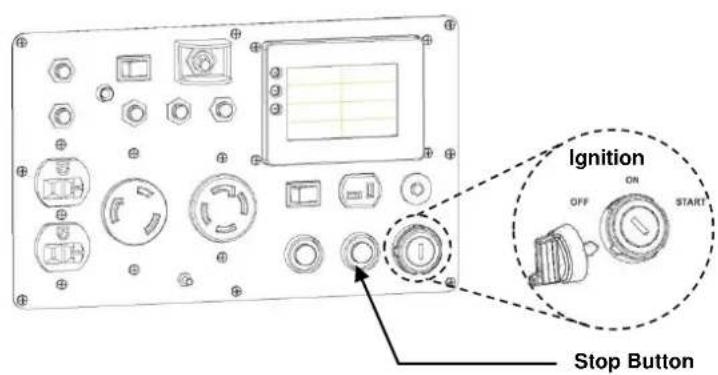
- Push the STOP button on the control panel. This will stop the unit with or without the ignition key or remote.
Normal shutdown
- Turn off the connected equipment and disconnect from the generator.
- If the remote control switch is "OFF", turn the ignition switch to the "OFF" position.
- If the remote control switch is "ON", push and hold the stop button on the remote or the stop button on the panel until the engine stops.


- Continually stopping the generator with a load applied can lead to damage of the control module.
- Always place the remote switch on the control panel in the "OFF" position when not in use for an extended period of time, to prevent running down the battery. The remote indicator light will illuminate and flash if the remote switch is on while the generator is not running.

5.16 Air conditioner operation
This generator can power up to two (2) 15,000 BTU air conditioners at the same time, but there are a few factors to keep in mind:
- Ensure that the generator has reach a normal operating temperature before applying the air conditioning load.
- Always allow a 2 minute wait period when manually cycling an air conditioner off and on. A longer wait period may be required under unusually hot weather conditions.
- All other loads should be turned off until the air conditioner has started and is performing normally.
- Follow the air conditioner manufacturer's instructions for starting and restarting your air conditioner(s) for proper operation.
- In some conditions it may be necessary to turn off the economy switch to achieve proper operation. These conditions include operating the generator at a high altitude, or operating in extreme temperatures, or using the generator to power two air conditioners at the same time. Since air conditioners can draw a lot of current when starting up, keeping the economy switch on can cause voltage fluctuation or shutdown.

NOTE
- An air conditioner can overload the generator by pulling too high a starting current if there is no start capacitor on the air conditioner. Some air conditioner manufacturers offer a start capacitor as an extra cost option. Contact your air conditioner dealer if you consistently have problems starting your air conditioner with the generator.
To power a single RV air conditioner with this generator, complete the following steps.
- Turn the voltage selector switch to 120V-only mode (to the left).
- Start the generator and let it run for 5-10 minutes to bring it up to normal operating temperature.
- Turn off the economy switch.
- Connect a shore power cable from the L5-30R AC receptacle on the control panel of the generator to the 30 A power connector of the RV. An adapter may be necessary.
- Turn on the air conditioner through the thermostat in your RV.

NOTE
- To provide enough current to run two air conditioners, you will need the two (2) isolated 120V AC circuits provided through the 240V L14-30R receptacle, which has an output of 50 amps.
To power two air conditioners from this generator, complete the following steps.
- Turn the voltage selector switch to 120V/240V mode (to the right).
- Start the generator and let it run for 5-10 minutes to bring it up to normal operating temperature.
- Turn off the Economy switch.
- Connect a shore power cable from the L14-30R AC receptacle on the control panel of the generator to the power connector of the RV. An adapter may be necessary.
- Turn on the air conditioner through the thermostat in your RV.
- Allow the unit to run for 20 seconds (for the air conditioner load to normalize) before turning the Economy switch back on.
6. MAINTENANCE
The purpose of the maintenance and adjustment schedule is to keep the generator in the best operating condition.
Inspect or service as scheduled in the table below.
For maximum performance, run your new generator at no more than 50% of the rated load of the generator for 4 hours before you apply a full load for the first time. The oil should be changed after the first 4 to 6 hours of operation to remove any manufacturing debris or contamination.

- Shut off the engine before performing any maintenance. If the engine must be run, make sure the area is well ventilated. The exhaust contains poisonous carbon monoxide gas.

- Use genuine POWERHOUSE® parts or the equivalent. The use of replacement parts which are not of equivalent quality may damage the generator. - When repairing or replacing the components of the emission control system, make sure to use the EPA standard components.
6.1 Emission Control System
Emission source
Exhaust gas contains carbon monoxide, nitrogen oxides ( NO_x ), and hydrocarbons. It is very important to control the emissions of NO_x and hydrocarbons as they are a major contributor to air pollution. Carbon monoxide is a poisonous gas. The emission of fuel vapors is a source of pollution as well. The POWERHOUSE® generator engine utilizes a precise air-fuel ratio and emission control system to reduce the emissions of carbon monoxide, NO_x , hydrocarbons, and evaporative fuel emissions.
Regulation
Your engine has been designed to meet current Environmental Protection Agency (EPA) and the California Air Resources Board (CARB) clean air standards. The regulations dictate that the manufacturer provides operation and maintenance standards regarding the emission control system. Tune up specifications are provided in the Specifications section and a description of the emission control system may be found in the appendix to this manual. Adherence to the following instructions will ensure your engine meets the emission control standards.
Modification
Modification of the emission control system may lead to increased emissions. Modification is defined as the following:
- Disassembling or modifying the function or parts of the intake, fuel or exhaust system.
- Modifying or destroying the speed governing function of the generator.
Engine faults that may affect emission
Any of the following faults must be repaired immediately. Consult with your authorized POWERHOUSE® service center for diagnosis and repair:
- Hard starting or shut down after starting.
- Unstable idle speed.
- Shut down or backfire after applying an electrical load.
- Backfire or after fire.
- Black smoke and/or excessive fuel consumption.
Replacement parts and accessories
The parts making up the emission control system applied to POWERHOUSE® engine have been specifically approved and certified by the regulatory agencies. You can trust that the replacement parts supplied by POWERHOUSE® have been manufactured to the same production standard as the original parts. The use of replacement parts or accessories which are not designed by POWERHOUSE® may affect the engine emission performance. The manufacturers of replacement parts and accessories have the responsibility to guarantee that their replacement products will not adversely affect emission performance.
Maintenance
Maintain the generator according to the maintenance schedule in this section. Service items more frequently when used in dusty areas, or under conditions of high load, temperature, and humidity.
Air Quality Index (only for California certified models)
CARB requires that an air quality index label be attached to every certified engine showing the engine emission information for the emission duration period. The label is provided for the user to compare the emission performance of different engines. The lower the air index, the better the engine emission performance. The description of durability is helpful for the user to learn the engine emission duration period and the service life of emission control system. Refer to the Warranty section of this owner's manual for more information.
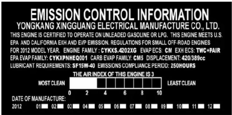
(Example label)
6.2 Maintenance Schedule
| Item | Maintenance Procedure | Regular Service period (1). Perform at every indicated month or operating hour interval, whichever occurs first. | ||||
| Each Use | 1^st Month or 4 to 6 Hours | Every 3 Months or 50 Hours | Every 6 Months or 100 Hours | 1x per Year Or 300 Hours | ||
| Engine Oil | Check | ○ | ||||
| Change | ○ | ○ | ||||
| Air cleaner | Check | ○ | ||||
| Clean | ○(2) | |||||
| Spark Plug | Clean / Adjust | ○ | ||||
| Spark Arrester | Clean | ○ | ||||
| Fuel Filter | Check | ○ | ||||
| Replace | ○(2) | |||||
| Valve clearance | Check / Adjust | ○(3) | ||||
| Fuel tank & strainer | Clean | ○(2) | ||||
| Fuel line | Check | Every 2-years (Replace as necessary) (3) | ||||
| Battery | Clean / Charge | Charge monthly during long term storage.Check terminals for corrosion monthly, clean as needed.Expected battery life is 2 years, but can be affected by operating environment. | ||||

NOTE
(1) Log hours of operation to determine proper maintenance.
(2) Service more frequently when used in dusty areas.
(3) These items should be serviced by an authorized dealer unless the owner has the proper tools and is mechanically proficient. See the Service Manual.
| Service Period for Oil Changes | Normal Operating Temperature |
| Normal –100 hr | 77°F (25°C) |
| 95 hr | 86°F (30°C) |
| 85 hr | 95°F (35°C) |
| 70 hr | 104°F (40°C) |
6.3 Changing oil
Drain the oil while the engine is still warm to assure rapid and complete draining.
CAUTION
• Make sure to turn the ignition switch "OFF" before draining the oil.
- Loosen the maintenance door screws and remove the maintenance door.
- Remove the oil drain screw. The oil will drain through a vent in the bottom of the generator case.
- Drain dirty oil into a container. Be sure to allow time for the oil to drain completely.
- Replace the oil drain screw.
- Refill with the recommended oil, and check to be sure the oil level is at the upper line on the dipstick. You do not have to screw in the dipstick all the way to check the level.
- Replace the oil dip stick.
- Reinstall the maintenance door and tighten the screws securely.

(-18°C)
(0°C)
(45°C)
Recommended oil is SAE 15W-40 when ambient temperature is above 32°F (0°C).
SAE 0W-40 is recommended if operating temperatures are below 32°F (0°C).
Synthetic oil is approved for use in POWERHOUSE® generators, and is recommended for operating the generator in temperatures below 32^ F.
Engine oil capacity: 37.2 fl oz (1.1 L)
NOTE
- Please dispose of used motor oil in a manner that is compatible with the environment and local disposal regulations. Do not throw it in the trash or pour it on the ground.


6.4 Air cleaner service
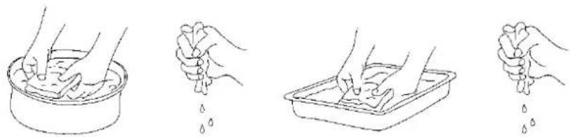
A dirty air cleaner will restrict air flow to the carburetor. To prevent carburetor malfunction, service the air cleaner regularly. Service more frequently when operating the generator in extremely dirty areas.

- Do not use gasoline or low flash point solvents for cleaning. They are flammable and explosive under certain conditions.
- Never run the generator without the air cleaner; rapid engine wear may result.

- Loosen the cover screws and remove the maintenance door.
- Remove the cartridge retaining screws. Remove the cartridge and check the element. Clean or replace the element if necessary.
- Wash the element in a non-flammable or low flash point solvent and dry it thoroughly.
- Soak the element in clean engine oil and squeeze out the excess oil.
- Reinstall the air filter element and the air cleaner cartridge. Tighten the cartridge screws securely.
- Reinstall the maintenance door and tighten the screws securely.

natural_image
Four-step illustration showing hands washing a cup, holding drops, cleaning a tray, and splashing water (no text or symbols)6.5 Spark plug service
Recommended spark plug: F7RTC
To ensure proper engine operation, the spark plug must be properly gapped and free of deposits.
- Loosen the cover screws and remove the maintenance door.
- Remove the spark plug cap.
- Clean any dirt from around the spark plug base.
- Use the supplied wrench to remove the spark plug.
- Visually inspect the spark plug. Discard it if the insulator is cracked or chipped.
- Clean the spark plug with a wire brush if it is to be reused.
- Measure the plug gap with a feeler gauge. The gap should be 0.028-0.031 in (0.7-0.8mm).
- Correct as necessary by carefully bending the side electrode.


- Install the spark plug carefully, by hand, to avoid cross-threading.
- After a new spark plug has been seated by hand, it should be tightened 1/2 turn with a wrench to compress the gasket. If a used plug is being reinstalled, it should only require 1/8 to 1/4 turn after being seated.
- Reinstall the spark plug cap securely on the spark plug.
- Replace the maintenance door.

- The spark plug must be securely tightened. An improperly tightened plug can become very hot and possibly damage the generator.
- Never use a spark plug with an improper heat range.
- Always use an F7RTC resistor-type spark plug. Using a non-resistor spark plug will interfere with AC output and the electronics, and may prevent the engine from starting.
6.6 Spark arrester maintenance


- If the generator has been running, the muffler will be very hot. Allow it to cool before proceeding.
- The spark arrester must be serviced every 100 hours to maintain its efficiency, or a decrease in horsepower may occur.
- Because of the size of the spark arrester opening in the exhaust grill you may decide that you do not want to take off the grill. This will not cause an issue unless you drop the arrester or the clamp or screws behind the grill. Taking the grill off or leaving it on is a matter of your convenience, but the procedure below will include removing the grill.

- Remove the exhaust grill to access the spark arrestor.
- Remove the screws holding the clamp and the spark arrester to the muffler.
- Clean the spark arrestor with a stiff wire brush.
- Replace if the wire mesh is perforated or torn.
- Reinstall the spark arrester and the clamp.
- Reinstall the exhaust grill.
7. TRANSPORTING & STORAGE
7.1 Transporting the Generator
To prevent fuel spillage when transporting or during temporary storage, the generator should be secured upright in its normal operating position with the fuel valve, ignition switch and remote switch turned "OFF".
When transporting the generator:

- Do not operate the generator while it is on or in a vehicle.
- If you must transport the generator in an enclosed vehicle, drain all fuel from the generator.
7.2 Short term storage of the Generator
During short term storage, the generator should be secured upright in its normal operating position with the fuel valve and engine switch turned "OFF".
Avoid placing the generator in direct sunlight when storing.
If the generator is left in an enclosed area or vehicle, high temperatures inside could cause residual fuel to vaporize resulting in possible explosion.
7.3 Infrequent use

• Gasoline is extremely flammable and explosive under certain conditions.
- Do not smoke or allow flames or sparks in the area.
- During long-term storage, or infrequent use of your equipment, it is important to add a fuel stabilizer, such as STA-BIL® Fuel Stabilizer, to help prevent fuel oxidation (breakdown) and the formation of gum and varnish, and to inhibit corrosion in the fuel system and carburetor.

- Be sure the storage area is free of excessive humidity and dust, and out of direct sunlight.
- It is best to keep the tank at least 95% full, as condensation will be less likely to occur in the fuel tank during storage if the tank is full. Do not overfill the tank, as the fuel will need room to expand on hot days. Add an appropriate amount of fuel stabilizer (per the instructions on the bottle) and run the generator for 5 minutes to ensure that any fuel trapped in the system has the stabilizer in it. You may also opt to add the fuel stabilizer and run the unit until it is out of fuel.
If you opt to drain the fuel, then continue on with the instructions below.
- To drain the gasoline from the fuel tank, turn the engine switch to the "OFF" position.
- Attach a hose to the drain fitting on the carburetor and place the other end of the hose into an approved gasoline container.
- Turn the fuel valve to the "ON" position, and loosen the carburetor drain screw and drain the gasoline into the approved gasoline container.
- After the fuel tank has been drained, with the drain screw loosened, disconnect the spark plug wire and turn the ignition key to the START position for a few cycles to drain the gasoline from the fuel pump.
- Turn the fuel valve to the "OFF" position, and tighten the drain screw securely.
- Change the engine oil.
- Remove the spark plug and pour about a tablespoon of clean engine oil into the cylinder.
- Turn the ignition key to the START position for a few cycles to distribute the oil.
- For safety, and if you have one available, use a compression gauge to bring the piston to the start of its compression stroke by inserting the rubber nipple of the gauge into the spark plug hole and turning the ignition key to the START position until you read the rated compression (51 psi). At this point, both the intake and exhaust valves will be closed. It may take a few attempts to reach the correct point in the cycle. Storing the engine in this position will help to protect it from internal corrosion.
- Remove the compression gauge and then reinstall the spark plug.
- Turn the remote switch to the "OFF" position to prevent unwanted, unintentional cranking and excessive battery drain.
- Once a month, recharge the battery. If a battery is allowed to drop below approximately 10.5 volts, it may not be recoverable by recharging, and you might have to replace the battery.
7.4 Exercising the Generator
It is essential that the generator be exercised on a regular basis. This will prevent the accumulation of varnish or sludge in the fuel system; remove moisture from the generator windings and help keep the battery properly charged. Additionally the engine seals and moving components will be lubricated. Exercise the generator by running it with at least a 1/2 load (3000W) for 15 minutes per month. Gasoline fuel treatments (such as STA-BIL®) to prevent contamination of your fuel supply are available from your dealer. Fuel varnishing necessitating replacement of the carburetor is not a warrantable failure.
8. TROUBLESHOOTING
8.1 Engine will not start

flowchart
graph TD
    A["Is there fuel in the tank?"] -->|YES| B["Is the fuel valve open and the ignition switch on?"]
    A -->|NO| C["Refuel the fuel tank."]
    B -->|YES| D["Is there enough oil in the engine?"]
    B -->|NO| E["Open the fuel valve and turn the ignition switch to the "START" position."]
    D -->|YES| F["Is there a spark from the spark plug?"]
    D -->|NO| G["Add the recommended oil."]
    F --> H["Warning: Be sure there is no spilled fuel around the spark plug.<br>Spilled fuel may ignite."]
    H -->|YES| I["If the engine still does not start, take it to an authorized POWERHOUSE® dealer."]
    H -->|NO| J["Replace the spark plug."]
    J --> K["Still no Spark"]
    K --> L["Take the generator to an authorized POWERHOUSE® dealer."]
    L --> M["To check spark: 1. Remove the spark plug cap and clean any dirt from around the spark plug.<br>2. Remove the spark plug and install the spark plug in the plug cap.<br>3. Attach the plug side electrode to your ground wire.<br>4. Quickly turn the key in the ignition to START position for a few cycles -- sparks should jump across the gap."]
    M --> N["Ground Wire"]
    M --> O["Spark Plug"]
    N --> P["Spark Plug boot"]
8.2 Engine will not crank with the key or remote start

flowchart
graph TD
    A["Are you out of range to use the key fob?"] -->|NO| B["Is the key fob battery drained?"]
    B -->|YES| C["Move to within 75' of the generator and retry."]
    B -->|NO| D["Is the remote switch turned off?"]
    D -->|YES| E["Replace the key fob battery."]
    D -->|NO| F["Is the battery fuse missing or burned out?"]
    F -->|YES| G["Replace the fuse."]
    F -->|NO| H["Is the battery dead?"]
    H -->|YES| I["Charge or replace the battery."]
    H -->|NO| J["Check all electrical connections between battery, control panel and electric starter."]
    J -->|NO| K["Take the generator to an authorized POWERHOUSE® service center."]
8.3 Appliance does not operate

flowchart
graph TD
    A["Is the circuit breaker "ON"?"] -->|YES| B["Is the digital display on and returning data?"]
    A -->|NO| C["Reset the circuit"]
    B -->|YES| D["Is a red overload indicator light on?"]
    B -->|NO| E["Are there any defects in the electrical appliance or equipment? Check for power using a meter, or a known good appliance."]
    D -->|YES| F["Take the generator to an authorized POWERHOUSE® service center."]
    D -->|NO| G["Did pressing the overload reset button cause the appliance to operate?"]
    F -->|YES| H["Replace the electrical appliance or equipment. Take the electrical appliance or equipment to an electrical shop for repair."]
    F -->|NO| I["Press the overload reset button."]
8.4 No output at the DC receptacle

flowchart
graph TD
    A["Is the DC circuit breaker tripped?"] -->|YES| B["Reset the circuit breaker."]
    A -->|NO| C["Is the internal voltage regulator fuse blown?"]
    C -->|YES| D["Replace the fuse."]
    C -->|NO| E["Take the generator to an authorized POWERHOUSE® service center."]
8.5 Digital display is illuminated but there is no data
Take the generator to an authorized POWERHOUSE® service center.
9. SPECIFICATIONS
Generator
| Model | PH6500Ri |
| Rated frequency (Hz) | 60 |
| Rated voltage (V) | 120 |
| Rated current (A) | 50.0 |
| Max current (A) | 54.0 |
| Rated output (W) | 6000 |
| Max output (W) | 6500 |
| DC Output | 12 V, 8.3 A |
| Phase | Single |
| Battery | 12 V |
| Battery fuse | 20 Amp, ATC style |
| Air pressure for pneumatic tires | 24 PSI |
Engine
| Model | 190F |
| Type | 4 stroke, 1-cylinder, air-cooled, OHV, gasoline engine |
| Horsepower/Displacement | 11.6/420cc |
| Compression ratio | 8.5:1 |
| Engine speed | 3700 RPM +/- 100 RPM with economy switch off2700 RPM +/- 100 RPM with economy switch on |
| Ignition system | Electronic (T.C.I.) |
| Spark plug | F7RTC |
| Starting system | Remote & Electric |
| Fuel | Automotive unleaded gasoline |
| Lube oil (synthetic or conventional) | SAE 15W-40 (0W-40 below 32°F) |
| Oil Capacity | 37.2 fl oz (1.1 L) |
| Fuel tank capacity | 5.8 gal (22 L) |
| Continuous running time at (rated output) | 5.3 hours |
| Continuous running time at ( 14 load ) | 12.8 hours |
| Continuous running time at ( 12 load ) | 8.4 hours |
| Noise level (no load - full load) dB@ 23' (7m) | 73 – 78 dB |
Tune Up Specifications
| Spark Plug Gap | 0.028 - 0.031 in (0.7 - 0.8 mm) |
| Valve Clearance (Intake) | 0.0047 - 0.0059 in (0.12 - 0.15 mm) |
| Valve Clearance (Exhaust) | 0.0059-0.0071 in (0.15 - 0.18 mm) |
Dimensions
| Overall dimension H×W×D in (mm) | 29.5" x 28" x 32" (749 x 711 x 813mm) |
| Dry weight, with battery | 186 lbs (84kg) |
10. WARRANTY AND CONSUMER INFORMATION
POWERHOUSE® GENERATOR WARRANTY
Generators are covered by this warranty from the date of original retail purchase for a period of 2 years or 1000 hours (whichever expires first) for residential use and 1 year or 500 hours (whichever expires first) for commercial applications. Units used in rental fleets, reconditioned or as demonstration models will be considered commercial usage. Starting batteries that are supplied with applicable products as standard, original equipment will be covered for a period of 6 months. The warranty coverage is continual from the original date of purchase, and does not restart upon the replacement of any part or complete unit. Individual parts replaced at any point during the warranty period are only eligible for warranty coverage for the balance of the original warranty period.
Eligibility
To be eligible for warranty replacement, the product must be purchased in the United States or Canada from an authorized POWERHOUSE® dealer. This warranty applies to the original retail purchaser only, and is not transferable. Proof of purchase and the serial number is required.
Coverage
Pre-approved parts and labor costs will be covered by POWERHOUSE® for any failure that is proven to be a failure in material or workmanship under normal use during the applicable warranty time period. This coverage is limited to parts, labor and ground shipping of repair parts. It is the responsibility of the end user to return the product to the nearest authorized repair center as directed by the warranty administration center. If in the event that the generator is deemed to be not repairable or the necessary repair would be economically unfeasible, the warranty department will authorize it's prepaid return to the nearest location and Coast will prepay the returned shipping to the dealer, repair center or consumer. Coast Distribution reserves the right to repair or replace any part or unit at its option. Coast Distribution may request defective parts to be returned. Anything replaced under warranty becomes the property of Coast Distribution.
To Obtain Warranty Service
Do not return this generator to the store where you purchased it. Contact any authorized dealer or contact our national customer service center at:
Phone: 1-877-544-4449 (8am to 6pm ET)
Fax: 1-800-263-0280
E-mail: www.powerhouse-products.com
If contacting us by fax or e-mail, be sure to include a description of the problem as well as all return contact info such as address, phone number, fax number, e-mail, etc. Engine serial number and proof of purchase is required.
Exclusions
THIS WARRANTY DOES NOT EXTEND TO PARTS AFFECTED OR DAMAGED BY ACCIDENT AND/OR COLLISION, NORMAL WEAR, FUEL CONTAMINATION OR DEGRADATION, USE IN AN APPLICATION FOR WHICH THE PRODUCT WAS NOT DESIGNED OR ANY OTHER MISUSE, NEGLECT, INCORPORATION OR USE OF UNSUITABLE ATTACHMENTS OR PARTS, UNAUTHORIZED ALTERATION, OR ANY CAUSES OTHER THAN DEFECTS IN MATERIAL OR WORKMANSHIP OF THE PRODUCT. THIS WARRANTY DOES NOT EXTEND TO NORMAL MAINTENANCE ITEMS SUCH AS BELTS, HOSES, SPARK PLUGS, REMOTE BATTERIES, WHEELS AND FILTERS PAST THE FIRST SCHEDULED REPLACEMENT OR SERVICE INTERVAL FOR THESE ITEMS WHICHEVER COMES FIRST.
Disclaimer of consequential Damage and Limitation of Implied Warranties
COAST DISTRIBUTION DENIES ANY RESPONSIBILITY FOR LOSS OF TIME OR USE OF THE PRODUCT, TRANSPORTATION, COMMERCIAL LOSS, OR ANY OTHER INCIDENTAL OR CONSEQUENTIAL DAMAGE. ANY IMPLIED WARRANTIES ARE LIMITED TO THE DURATION OF THIS WRITTEN LIMITED WARRANTY.
Some states do not allow limitations on how long an implied warranty lasts and/or do not allow the exclusion or limitation of incidental or consequential damages. Therefore, the above exclusions and limitations may not apply to you. This warranty gives you specific legal rights, and you may also have other rights, which vary from state to state.
Replacement Parts Availability
To purchase replacement parts please refer to the www.powerhouse-products.com website.
CALIFORNIA EMISSIONS CONTROL WARRANTY STATEMENT
Your Warranty Rights and Obligations
The California Air Resources Board and Coast Distribution System Inc. (POWERHOUSE®). are pleased to explain the emissions control system warranty on your 2008 and later small off-road engine (SORE). In California, new SOREs must be designed, built and equipped to meet the State's stringent anti-smog standards. Coast Distribution System Inc. (POWERHOUSE®) must warrant the emissions control system on your SOREs for the periods of time listed below provided there has been no abuse, neglect or improper maintenance of your SOREs.
Your emission control system may include parts such as the carburetor, fuel tanks, fuel caps, fuel lines, the ignition system, and catalytic converter. Also included may be hoses, belts, clamps, connectors and other emission-related assemblies.
Where a warrantable condition exists, Coast Distribution System Inc. will repair your small off-road engine at no cost to you including diagnosis, parts and labor.
Manufacturer's Warranty Coverage
The emissions control system is warranted for two years. If any emissions-related part on your engine is defective, the part will be repaired or replaced by Coast Distribution System Inc.
Owner's Warranty Responsibilities
- As the SORE owner, you are responsible for the performance of the required maintenance listed in your owner's manual. Coast Distribution System Inc. recommends that you retain all receipts covering maintenance on your SORE, but Coast Distribution System Inc. (POWERHOUSE®) can not deny warranty solely for the lack of receipts or for your failure to ensure the performance of all scheduled maintenance.
- As the SORE owner, you should however be aware that Coast Distribution System Inc. may deny your warranty coverage if your SORE or a part has failed due to abuse, neglect, improper maintenance or unapproved modifications.
- You are responsible for presenting your SORE to a distribution center or service center authorized by Coast Distribution System Inc. (POWERHOUSE®) as soon as the problem exists. The warranty repairs should be completed in a reasonable amount of time, not to exceed 30 days.
If you have any questions regarding your warranty coverage, you should contact the North America service center for POWERHOUSE® products:
Phone: 1-877-544-4449
Fax: 1-800-263-0280
Email: www.powerhouse-products.com
EMISSION CONTROL SYSTEM WARRANTY
Your POWERHOUSE® generator engine complies with U.S. Environmental Protection Agency, Environment of Canada, and the state of California (if the model is certified by CARB). The following systems and/or parts are covered by this warranty. Failures or improper operation of the following systems and components will be diagnosed and repaired with no charge for labor or parts.
Fuel System
• Carburetor including the choke system
• Engine speed control system (Economy Throttle)
- Intake manifold
• Engine control module
Evaporative Control System
- Fuel tank
- Fuel cap
- Fuel strainer
- Fuel valve
- Fuel pump
- Fuel lines
• Carbon canister (including brackets and connectors)
Air Induction System
- Air filter element*
- Air filter housing
Ignition system
- Ignition module
- Ignition coil
- Ignition winding
- Spark plug*
- Spark plug cap and wire
Exhaust system
- Catalyst
- Exhaust manifold
• Secondary air injection assembly
Miscellaneous
- Pipes, tubes, hoses and clamps, o-rings, seals, and gaskets associated with the above systems.
* Covered up to the first scheduled replacement only. See the maintenance schedule.
11. APPENDIX A - EMISSION CONTROL SYSTEM
Your generator has an engine that has been approved by the California Air Resources Board. Other than the tune up procedures specified in the Maintenance section, no additional maintenance is required.
The emission control system has the following components:
- Fuel System: The fuel tank, cap, indicator and hoses are specially designed and constructed to not allow fuel vapors to permeate and be released to the atmosphere.
- A carbon activated canister collects gasoline vapors from the fuel tank and returns them to the combustion chamber for burning.
- A catalyst is built into the muffler to further treat the engine exhaust.
- A secondary air injection valve adds combustion air to ignite unburned fuel in the exhaust.
Contact your authorized POWERHOUSE® service center to obtain the correct replacement parts and service on this system.
12. APPENDIX B - SAFETY AND CHARGING INSTRUCTIONS
(a) SAVE THESE INSTRUCTIONS. THIS MANUAL CONTAINS IMPORTANT SAFETY AND OPERATING INSTRUCTIONS.
(b) WORKING IN THE VICINITY OF A LEAD-ACID BATTERY IS DANGEROUS. BATTERIES GENERATE EXPLOSIVE GASES DURING NORMAL BATTERY OPERATION. FOR THIS REASON IT IS OF THE UTMOST IMPORTANCE THAT EACH TIME BEFORE USING YOUR CHARGER, YOU READ AND FOLLOW THE INSTRUCTIONS PROVIDED EXACTLY.
(c) TO REDUCE RISK OF BATTERY EXPLOSION, FOLLOW THESE INSTRUCTIONS AND THOSE MARKED ON THE BATTERY.
(d) NEVER SMOKE OR ALLOW AN OPEN SPARK OR FLAME IN THE VICINITY OF THE BATTERY OR ENGINE.
(e) USE CHARGER FOR CHARGING A LEAD-ACID BATTERY ONLY. IT IS NOT INTENDED TO SUPPLY POWER TO AN EXTRA-LOW-VOLTAGE ELECTRICAL SYSTEM OR TO CHARGE DRY-CELL BATTERIES. CHARGING DRY-CELL BATTERIES MAY CAUSE THEM TO BURST AND CAUSE INJURY TO PERSONS AND DAMAGE TO PROPERTY.
(f) NEVER CHARGE A FROZEN BATTERY.
(g) IF IT IS NECESSARY TO REMOVE BATTERY FROM VEHICLE TO CHARGE IT, ALWAYS REMOVE GROUNDED TERMINAL FROM BATTERY FIRST. MAKE SURE ALL ACCESSORIES IN THE VEHICLE ARE OFF IN ORDER TO PREVENT AN ARC.
(h) STUDY ALL BATTERY MANUFACTURER'S SPECIFIC PRECAUTIONS SUCH AS REMOVING OR NOT REMOVING CELL CAPS WHILE CHARGING AND RECOMMENDED RATES OF CHARGE.
(i) FOR A CHARGER HAVING AN OUTPUT VOLTAGE SELECTOR SWITCH, REFER TO THE CAR OWNER'S MANUAL IN ORDER TO DETERMINE THE VOLTAGE OF THE BATTERY AND TO MAKE SURE THE OUTPUT VOLTAGE IS SET AT THE CORRECT VOLTAGE. IF AN OUTPUT VOLTAGE SELECTOR SWITCH IS NOT PROVIDED, DO NOT USE THE BATTERY CHARGER UNLESS THE BATTERY VOLTAGE MATCHES THE OUTPUT VOLTAGE RATING OF THE CHARGER.
(j) NEVER PLACE THE CHARGER DIRECTLY ABOVE OR BELOW THE BATTERY BEING CHARGED; GASES OR FLUIDS FROM THE BATTERY WILL CORRODE AND DAMAGE THE CHARGER. LOCATE THE CHARGER AS FAR AWAY FROM THE BATTERY AS DC CABLES PERMIT.
(k) DO NOT OPERATE CHARGER IN A CLOSED-IN AREA OR RESTRICT VENTILATION IN ANY WAY.
(I) CONNECT AND DISCONNECT DC OUTPUT CLIPS ONLY AFTER SETTING ANY CHARGER SWITCHES TO THE OFF POSITION AND REMOVING AC CORD FROM THE ELECTRIC OUTLET. NEVER ALLOW CLIPS TO TOUCH EACH OTHER.
(m) FOLLOW THESE STEPS WHEN BATTERY IS INSTALLED IN VEHICLE. A SPARK NEAR BATTERY MAY CAUSE A BATTERY EXPLOSION. TO REDUCE RISK OF A SPARK NEAR BATTERY:
i. POSITION AC AND DC CORDS TO REDUCE RISK OF DAMAGE BY HOOD, DOOR, OR MOVING ENGINE PARTS;
ii. STAY CLEAR OF FAN BLADES, BELTS, PULLEYS, AND OTHER PARTS THAT CAN CAUSE INJURY TO PERSONS;
iii. CHECK POLARITY OF BATTERY POSTS. A POSITIVE (POS, P, +) BATTERY POST USUALLY HAS A LARGER DIAMETER THAN A NEGATIVE (NEG, N, −) POST;
iv. DETERMINE WHICH POST OF BATTERY IS GROUNDED (CONNECTED) TO THE CHASSIS. IF NEGATIVE POST IS GROUNDED TO CHASSIS (AS IN MOST VEHICLES), SEE ITEM (v). IF POSITIVE POST IS GROUNDED TO THE CHASSIS, SEE ITEM (vi);
v. FOR A NEGATIVE-GROUNDED VEHICLE, CONNECT THE POSITIVE (RED) CLIP FROM BATTERY CHARGER TO POSITIVE (POS, P, +) UNGROUNDED POST OF BATTERY. CONNECT THE NEGATIVE (BLACK) CLIP TO VEHICLE CHASSIS OR ENGINE BLOCK AWAY FROM BATTERY. DO NOT CONNECT CLIP TO CARBURETOR, FUEL LINES, OR SHEET-METAL BODY PARTS. CONNECT TO A HEAVY GAUGE METAL PART OF THE FRAME OR ENGINE BLOCK;
vi. FOR A POSITIVE-GROUNDED VEHICLE, CONNECT THE NEGATIVE (BLACK) CLIP FROM BATTERY CHARGER TO NEGATIVE (NEG, N, -) UNGROUNDED POST OF BATTERY. CONNECT THE POSITIVE (RED) CLIP TO VEHICLE CHASSIS OR ENGINE BLOCK AWAY FROM BATTERY. DO NOT CONNECT CLIP TO CARBURETOR, FUEL LINES, OR SHEET-METAL BODY PARTS. CONNECT TO A HEAVY GAUGE METAL PART OF THE FRAME OR ENGINE BLOCK;
vii. CONNECT CHARGER AC SUPPLY CORD TO ELECTRIC OUTLET; AND
viii. WHEN DISCONNECTING CHARGER, TURN SWITCHES TO OFF, DISCONNECT AC CORD, REMOVE CLIP FROM VEHICLE CHASSIS, AND THEN REMOVE CLIP FROM BATTERY TERMINAL.
(n) FOLLOW THESE STEPS WHEN BATTERY IS OUTSIDE VEHICLE. A SPARK NEAR THE BATTERY MAY CAUSE A BATTERY EXPLOSION. TO REDUCE RISK OF A SPARK NEAR BATTERY:
i. CHECK POLARITY OF BATTERY POSTS. A POSITIVE (POS, P, +) BATTERY POST USUALLY HAS A LARGER DIAMETER THAN A NEGATIVE (NEG, N, -) POST;
ii. ATTACH AT LEAST A 60 CM 6-GAUGE (AWG) INSULATED BATTERY CABLE TO A NEGATIVE (NEG, N, -) BATTERY POST;
iii. CONNECT THE POSITIVE (RED) CHARGER CLIP TO THE POSITIVE (POS, P, +) POST OF BATTERY;
iv. POSITION YOURSELF AND THE FREE END OF CABLE AS FAR AWAY FROM BATTERY AS POSSIBLE, THEN CONNECT THE NEGATIVE (BLACK) CHARGER CLIP TO FREE END OF CABLE;
v. DO NOT FACE BATTERY WHEN MAKING FINAL CONNECTION;
vi. CONNECT CHARGER AC SUPPLY CORD TO ELECTRICAL OUTLET; AND
vii. WHEN DISCONNECTING CHARGER, ALWAYS DO SO IN REVERSE SEQUENCE OF CONNECTING PROCEDURE AND BREAK FIRST CONNECTION WHILE STANDING AS FAR AWAY FROM BATTERY AS PRACTICAL.
(o) USE OF AN ADAPTER IS NOT ALLOWED IN CANADA. IF A GROUNDING TYPE RECEPTACLE IS NOT AVAILABLE, DO NOT USE THIS APPLIANCE UNTIL THE PROPER OUTLET IS INSTALLED BY A QUALIFIED ELECTRICIAN.
(p) THE GENERATOR (STATOR WINDING) IS ISOLATED FROM THE FRAME AND FROM THE AC RECEPTACLE GROUND PIN.
(q) ELECTRICAL DEVICES THAT REQUIRE A GROUNDED RECEPTACLE PIN CONNECTION WILL NOT FUNCTION IF THE RECEPTACLE GROUND PIN IS NOT FUNCTIONAL.

natural_image
Black powerbox with attached cylindrical device and wheels, no visible text or symbols on bodyPOWERHOUSE® Products
DTS Manufacturing
7930 S.W. Burns Way, Unit C
Wilsonville, OR 97070
www.powerhouse-products.com
BCN # Label For This Unit
Remote Serial Number Label
This manual version applies to BCNs equal to or greater than:
- PH6500Ri Digital Inverter Generator
- QUICK START
- WARNING
- Pre-Operation
- NOTE
- CAUTION
- Operation
- Electric Start:
- Remote Start:
- Shutdown
- FCC INFORMATION
- Notice
- PREFACE
- Pay special attention to statements preceded by the following words:
- TABLE OF CONTENTS
- SAFETY INSTRUCTIONS
- To ensure safe operation
- COMPONENT IDENTIFICATION
- PH6500Ri Generator
- PH6500Ri Control Panel
- Serial number and bar code identification and location
- USING THE HANDLES
- PRE-OPERATION CHECK
- Check the Engine Oil Level
- Check the fuel level
- Gasoline containing alternate fuels
- Check the air cleaner
- Connecting the battery
- Battery removal and replacement
- Removal
- Replacement
- OPERATING INSTRUCTIONS
- Starting the engine
- Starting procedure using the Ignition Key
- Starting procedure using the remote function
- High Altitudes
- Operating at extreme temperatures
- Generator use
- 120V/240V Operation
- Digital display
- AC application
- Overload conditions
- Low voltage protection
- DC application
- Charging external batteries
- Powering 12V DC devices
- Back-charging the generator battery
- Jump-starting the generator
- Low oil alarm system
- Economy switch
- Stopping the engine
- To stop the engine in an emergency
- Normal shutdown
- Air conditioner operation
- MAINTENANCE
- Emission Control System
- Emission source
- Regulation
- Modification
- Engine faults that may affect emission
- Replacement parts and accessories
- Maintenance
- Air Quality Index (only for California certified models)
- Maintenance Schedule
- Changing oil
- Air cleaner service
- Spark plug service
- Spark arrester maintenance
- TRANSPORTING & STORAGE
- Transporting the Generator
- Short term storage of the Generator
- Infrequent use
- Exercising the Generator
- TROUBLESHOOTING
- Engine will not start
- Engine will not crank with the key or remote start
- Appliance does not operate
- No output at the DC receptacle
- Digital display is illuminated but there is no data
- SPECIFICATIONS
- WARRANTY AND CONSUMER INFORMATION
- POWERHOUSE® GENERATOR WARRANTY
- Eligibility
- Coverage
- To Obtain Warranty Service
- Exclusions
- Disclaimer of consequential Damage and Limitation of Implied Warranties
- Replacement Parts Availability
- CALIFORNIA EMISSIONS CONTROL WARRANTY STATEMENT
- Your Warranty Rights and Obligations
- Manufacturer's Warranty Coverage
- Owner's Warranty Responsibilities
- EMISSION CONTROL SYSTEM WARRANTY
- Fuel System
- Evaporative Control System
- Air Induction System
- Ignition system
- Exhaust system
- Miscellaneous
- APPENDIX A - EMISSION CONTROL SYSTEM
- APPENDIX B - SAFETY AND CHARGING INSTRUCTIONS
Brand : Powerhouse
Model : PH6500Ri
Category : Generator