
M30T - Subwoofer MARTIN - Free user manual and instructions
Find the device manual for free M30T MARTIN in PDF.


| Product Type | Full-range top-box (dedicated top-box with roll-off at 70 Hz) |
| Woofer | 15" (500W RMS, 8 ohms) |
| Compression Driver | 2" throat (125W RMS, 16 ohms) |
| Power Handling (Passive) | 500 W (woofer) + 125 W (tweeter), total 625 W |
| Impedance (Passive) | 8 ohms (woofer), 16 ohms (tweeter) |
| Crossover Frequency | 1.3 kHz, 24 dB/octave Linkwitz-Riley |
| High-pass Filter Requirement | Must use a 90 Hz high-pass filter |
| Operating Modes | Passive (internal crossover) and Active (bi-amp via external crossover) |
| Protection System | Double thermal protection for compression driver (active in both modes) |
| Flying System | Integrated 3-point flying system; compatible with Double Stud & Ring (P/N 93944003) |
| Speaker Connectors | Speakon (NL4) – passive: 1+/1-; active: 1+/1- (woofer), 2+/2- (tweeter) |
| Recommended Cable | 2x4, 4x4, or 8x4 mm² Mach speaker cable; lengths per table (e.g., 30 m for 2.5 mm² at 8 ohms) |
| Break-in Period | Approximately 20 hours at 70% output |
| Tools Required for Service | Woofer: 4 mm hex Allen key; Horn: 3 mm hex Allen key; Grill & crossover: Phillips PZ2 screwdriver |
| Certified Load (Flying Stud) | 274 kg at 45° angle with safety factor 7 |
Frequently Asked Questions - M30T MARTIN
User questions about M30T MARTIN
0 question about this device. Answer the ones you know or ask your own.
Ask a new question about this device
Download the instructions for your Subwoofer in PDF format for free! Find your manual M30T - MARTIN and take your electronic device back in hand. On this page are published all the documents necessary for the use of your device. M30T by MARTIN.
USER MANUAL M30T MARTIN
© 2000 - 2005 Martin Professional A/S, Denmark.
All rights reserved. No part of this manual may be reproduced, in any form or by any means, without permission in writing from Martin Professional A/S, Denmark.
Revision D
Printed in Denmark.
The Touring Series consists of two product types: the SlingShot series with 55^ x 35^ dispersion for long throw applications, and the T series with 55^ x 45^ dispersion for medium throw applications. Both types have the same horizontal dispersion, but the T series has greater dispersion in the vertical plane, making them ideal for down-fill applications in combination with SlingShots or as stand-alone boxes in applications where a wider vertical dispersion is desirable to address sloping audience areas. This manual applies to the T series.
The T series is designed to be used with any quality amplification equipment. There is no need for special processors. The design philosophy is that acoustic problems are best solved with acoustic solutions. As the most powerful processor cannot correct even basic acoustic problems, there is no substitute for the quality of an acoustically well designed speaker.
For this reason, all drive units have been developed with emphasis on ultra flat frequency response, highly controlled dispersion patterns and very low distortion. In addition, power compression has been kept to an absolute minimum.
- The M12T and M15T are full range boxes that work well without support from subwoofers.
- The M14T and M30T are dedicated top-boxes with a roll-off at around 70 Hz, but with extremely high output above this frequency.
- The M118T, M181T, M182T and M218T are sub-woofers.
- The M1201T and M1502T are full-range boxes designed for monitor applications.
PASSIVE MODE (INTERNAL CROSSOVER)
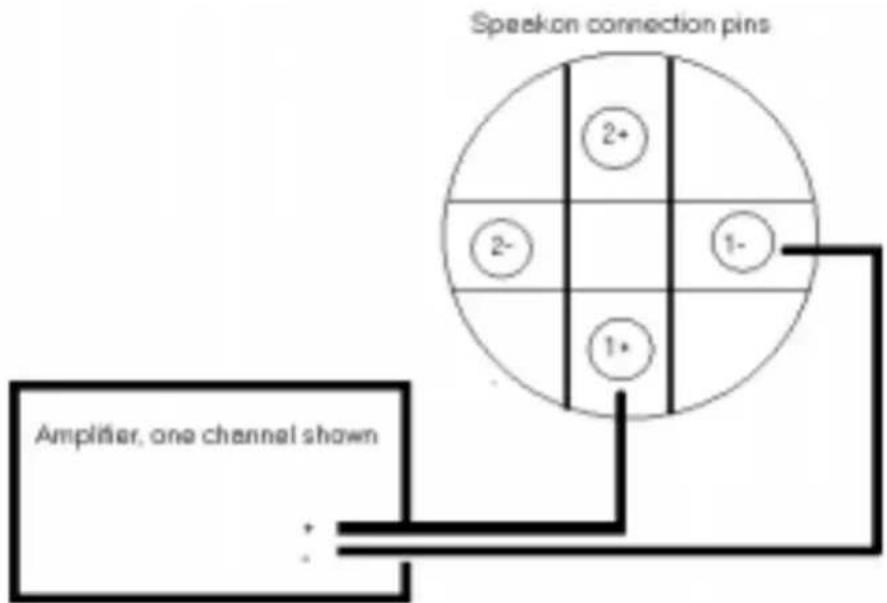
All models in the T-series are supplied in passive mode. In this mode, they are connected through the 1+/1- pins on the Speakon® plug, and the signal from the amplifier is fed to the passive internal crossover.
flowchart
graph TD
    A["Speaker connection pins"] --> B["Amplifier, one channel shown"]
    B --> C["Grid with nodes 1+, 2-, 1-"]
    C --> D["Grid with node 2+"]
    C --> E["Grid with node 2-"]
Figure 1: Default pin configuration (Passive Mode)
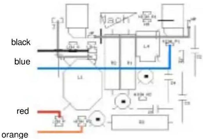
The internal crossover is located directly behind the Speakon® terminal. In passive mode operation, the crossover for all full-range models except the M14T is wired as shown below (crossover wiring for the M14T is shown on the next page):
M12T, M15T, M30T, M1201T, M1502T IN PASSIVE MODE:
- Red (Woofer +) to LOW P
- Black (Woofer -) to LOW -
• Orange (Tweeter +) to HIGH P1
• Blue (Tweeter -) to HIGH P2
• Jumper between HP and HP - Jumper between J and J

M14T IN PASSIVE MODE:
The M14T crossover is wired as shown below:
• Red (Woofer +) to LOW P
- Black (Woofer -) to LOW -
• Orange (Tweeter +) to HIGH P2
• Blue (Tweeter -) to HIGH P1
• Jumper between HP and HP
• Jumper between J and J
ACTIVE MODE (EXTERNAL CROSSOVER)
In active mode, low and high frequency signals from an external crossover are connected directly to woofers via the 1+/1- pins and compression drivers via the 2+/2- pins on the Speakon plug.

flowchart
graph TD
    A["Speaker connection pins"] --> B["Amplifier, high, one channel shown"]
    A --> C["Amplifier, low, one channel shown"]
    B --> D["+ (red)"]
    B --> E-["(black)"]
    C --> F["+ (red)"]
    C --> G-["(black)"]
    D --> H["2+"]
    E --> I["2-"]
    F --> J["1+"]
    G --> K["1-"]
Figure 2: Active mode pin configuration
ACTIVE MODE WIRING (ALL FULL-RANGE MODELS)
To run speakers in active mode, the internal crossover on all speakers must be rewired as shown below:
- Red (Woofer +) to LOW A
- Black (Woofer -) to LOW -
• Orange (Tweeter +) to HIGH A2 - Blue (Tweeter -) to HIGH A1
• Jumper between HA and HA - Remove jumper between J and J.

Table 1: Active mode specifications
| Model | Driver throat | Power handling IEC 268 | Impedance | Crossover point | Polarity |
| M12T | 2" 125 watt 16 ohm | 1.3kHz^a | Inverted | ||
| 12" 400 watt 8 ohm Normal | |||||
| M14T | 2" 150 watt 16 ohm | 1.4kHz^b | Normal | ||
| 15" 400 watt 8 ohm Normal | |||||
| M15T | 2" 125 watt 16 ohm | 1.3 kHz | Normal | ||
| 15" 500 watt 8 ohm Normal | |||||
| M30T | 2" 125 watt 16 ohm | 1.3kHz^c | Normal | ||
| 15" 500 watt 8 ohm Normal | |||||
| M1201T | 7/8" 50 watt 16 ohm | 1.6 kHz | Normal | ||
| 12" 315 watt 8 ohm Normal | |||||
| M1502T | 2" 80 watt 16 ohm | 1.5 kHz | Normal | ||
| 15" 490 watt 8 ohm Normal | |||||
a. All crossover slopes should be 24 dB Linkvitz Riley
b. The M14T must be used with a 90 Hz high-pass filter
c. The M30T must be used with a 90 Hz high-pass filter
All top-boxes in the Touring Series feature an integrated 3-point flying system. We recommend the Double Stud & Ring for flying track (P/N 93944003), manufactured by ATM, for use with all models. The certified load of the stud mounted into the flying track is 274 kg in 45^ with a security factor 7. A comprehensive flying manual is available.
PROTECTION SYSTEM
The crossover features a double thermal protection system that is active in both passive and active modes. When power to the compression driver exceeds a safe level, the protection system increases impedance and reduces power. The audible result is lower output from the horn. When this happens, do not increase the high frequency level on the EQ or tone control, as this may damage the protection circuit and eventually the compression driver.
When power returns to a safe level, the protection circuit restores full signal to the horn and the audio output returns to normal.
The thermal protection circuit combines efficient protection with excellent sound quality. It is, however, not a limiter; it is designed to catch momentary surges such as microphone feedback. If the protection system is continuously engaged it will develop a “memory” and come in at increasingly low levels. If this happens, either the system is under-specified or the amplifier is clipping.
CABLES
Always use high quality speaker cables. We recommend the 2x4, 4x4 or 8x4 mm ^2 Mach speaker cable. These are professional speaker cables featuring watertight rubber insulation with low sulphur content that ensures that the cable will not oxidize. The cables have low impedance, low capacitance, and are soft and easy to wind. For recommended cable lengths, refer to Table 2.
Table 2: Recommended cable lengths (dampening factor = 50)
| Cable size/load 8 ohms 4 ohms 2 ohms | |||
| 1.5 mm^2 (15 AWG) | 15 m (50 ft.) | 7.5 m (25 ft.) | 4 m (13 ft.) |
| 2.5 mm^2 (13 AWG) | 30 m (100 ft.) | 15 m (50 ft.) | 7.5 m (25 ft.) |
| 4.0 mm^2 (11 AWG) | 60 m (200 ft.) | 30 m (100 ft.) | 15 m (50 ft.) |
BREAK-IN PERIOD
As with all quality drivers, the drivers in the Mach T series need approximately 20 hours of operation at 70% output before they will perform fully to specifications.
The following tools are required for servicing the speakers.
TOP-BOXES & STAGE MONITORS
- Woofers: 4 mm hex Allen key
- Horns: 3 mm hex Allen key
SUBS
- Woofers: 6 mm hex Allen key
ALL MODELS
- Grill & crossover: ...... Phillips PZ2 screwdriver



Brand : MARTIN
Model : M30T
Category : Subwoofer