
1510 - Charger BatteryMINDer - Free user manual and instructions
Find the device manual for free 1510 BatteryMINDer in PDF.


| Product Type | Automatic Battery Charger and Maintainer |
| Brand | BatteryMINDer |
| Model | 1510 |
| Input Voltage | 120 VAC, 60 Hz |
| Output Voltage | 12V and 24V (selectable) |
| Charge Current | 1.5 Amps (max) |
| Battery Types | Flooded, AGM, Gel, and Lead-Acid |
| Features | Automatic desulfation, temperature compensation, float mode, reverse polarity protection |
| Dimensions (L x W x H) | 7.5 x 3.5 x 5.5 inches |
| Weight | 2.0 lbs (0.9 kg) |
| Cable Length | 6 feet AC cord, 4 feet DC cord with clamps |
| Safety Certifications | UL, CSA listed |
| Operating Temperature | -40°F to 140°F (-40°C to 60°C) |
| Warranty | 3 years limited |
| Maintenance | Wipe with dry cloth; keep vents clear; store in dry place |
| Repairability | No user-serviceable parts; contact authorized service for repairs |
Frequently Asked Questions - 1510 BatteryMINDer
User questions about 1510 BatteryMINDer
0 question about this device. Answer the ones you know or ask your own.
Ask a new question about this device
Download the instructions for your Charger in PDF format for free! Find your manual 1510 - BatteryMINDer and take your electronic device back in hand. On this page are published all the documents necessary for the use of your device. 1510 by BatteryMINDer.
USER MANUAL 1510 BatteryMINDer
both with SmarTECHnology®
12 Volt 1500 mA
Charger - Maintainer - Desulfator
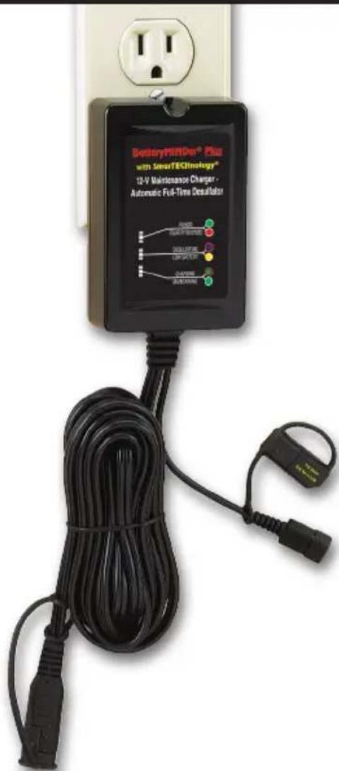
INCLUDES:
• Auto-Temp Compensation Sensor, installed (1500 & 1510)
- Optional Permanent Mounting Tab (1500 & 1510)
- Battery Clips (1500 Standard, Non-fused; 1510 Fully-Insulated Aircraft Grade, 15A replaceable fuse)
- Ring Terminal Assembly with 15A replaceable fuse (1510 only)
\*CAUTION:
• NOT FOR USE WITH AVIATION BATTERIES
• NOT FOR USE WITH LITHIUM TYPE BATTERIES; POTENTIAL FOR EXPLOSION MAY EXIST IF USED
READ AND SAVE THESE INSTRUCTIONS
VDC Electronics, Inc. • 155 W. Carver St., Ste. 2 • Huntington, NY 11743
www.BatteryMINDers.com • techsupport@vdcelectronics.com
TABLE of CONTENTS
REQUIRED SAFETY INSTRUCTIONS .... 3
WIRE GAUGE TABLE.... 3
PREPARING TO CHARGE.... 5
CHARGER LOCATION....5
DC CONNECTION PRECAUTIONS....6
LED INDICATION TABLE 8
START-UP OPERATING INSTRUCTIONS 9
SPECIFICATIONS 9
CHARGING STATUS....9
SPECIFICATIONS 9
CHARGING STAGES....10
ADDITIONAL FEATURES.... 10
VOLTAGE TABLE 10
12-V PARALLEL CONNECTION DIAGRAM 10
12-V SERIES-PARALLEL USING 6-V BATTERIES....10
6-V SERIES CONNECTION DIAGRAM 10
TROUBLESHOOTING....11
MAINTAINING MULTIPLE BATTERIES 11
MODEL CALL-OUTS.... 12
CHARGING CURVE 13
SAFETY & PROTECTION 14
ELECTRICAL CABLE & PHYSICAL PARAMETERS .... 14
FOR REPAIR OR REPLACEMENT....15
YOUR NOTES....15
GUARANTEE....16
WARRANTY....16
WARRANTY REGISTRATION .... 16
REQUIRED IMPORTANT SAFETY INSTRUCTIONS WARNING
TO REDUCE THE RISK OF FIRE, ELECTRIC SHOCK, OR INJURY TO PERSON, OBSERVE THE FOLLOWING:
1. SAVE THESE INSTRUCTIONS
This manual contains important safety and operating instructions for BatteryMINDer1500 and BatteryMINDer Plus 1510.
- Do not expose charger to rain or snow.
-
Use of an attachment not recommended or sold by VDC Electronics may result in a risk of fire, electric shock, or injury to persons.
-
To reduce risk of damage to electric plug and cord, pull by plug rather than cord when disconnecting charger.
-
An extension cord should not be used unless absolutely necessary. Use of improper extension cord could result in a risk of fire and electric shock. If an extension cord must be used, make sure:
a) That pins on plug of extension cord are the same number, size, and shape as those of plug on charger;
b) That extension cord is properly wired and in good electrical condition; and
c) That wire size is large enough for ac ampere rating of charger as specified in Table below.
TABLE 1
| Recommended minimum AWG size for extension cords for battery chargers | |||||
| AC input rating, amperesa | AWG size of cord | ||||
| Equal to or greater than | But less than | Length of cord, feet (m) | |||
| 25(7.6) | 50(15.2) | 100(30.5) | 150(45.6) | ||
| 0 | 2 | 18 | 18 | 18 | 16 |
| aIf the input rating of a charger is given in watts rather than in amperes, the corresponding ampere rating is to be determined by dividing the wattage rating by the voltage rating - for example: 1250 watts/125 volts = 10 amperes | |||||
- Do not operate charger with damaged cord or plug – replace the cord or plug immediately.
- Do not operate charger if it has received a sharp blow, been dropped, or otherwise damaged in any way; call VDC Electronics Tech Support Dept. 800.379.5579 x6 (ET) for advice.
- Do not disassemble charger; call VDC Electronics Tech Support Dept. 800.379.5579 x6 (ET) for advice when service or repair is required. Incorrect reassembly may result in a risk of electric shock or fire.
- To reduce risk of electric shock, unplug charger from outlet before attempting any maintenance or cleaning.
10. WARNING – RISK OF EXPLOSIVE GASES
a) WORKING IN VICINITY OF A LEAD-ACID BATTERY IS DANGEROUS. BATTERIES GENERATE EXPLOSIVE GASES DURING NORMAL BATTERY OPERATION. FOR THIS REASON, IT IS OF UTMOST IMPORTANCE THAT YOU FOLLOW THE INSTRUCTIONS EACH TIME YOU USE THE CHARGER.
b) To reduce risk of battery explosion, follow these instructions and those published by manufacturer of any equipment you intend to use in vicinity of battery. Review cautionary marking on these products and on engine.
11. PERSONAL PRECAUTIONS
a) Consider having someone close enough by to come to your aid when you work near a lead-acid battery.
b) Have plenty of fresh water and soap nearby in case battery acid contacts skin, clothing, or eyes.
c) Wear complete eye protection and clothing protection. Avoid touching eyes while working near battery.
d) If battery acid contacts skin or clothing, wash immediately with soap and water. If acid enters eye, immediately flood eye with running cold water for at least 10 minutes and get medical attention immediately.
e) NEVER smoke or allow a spark or flame in vicinity of battery or engine.
f) Be extra cautious to reduce risk of dropping a metal tool onto battery.
It might spark or short-circuit battery or other electrical part that may cause explosion.
g) Remove personal metal items such as rings, bracelets, necklaces, and watches when working with a lead-acid battery. A lead-acid battery can produce a short-circuit current high enough to weld a ring or the like to metal, causing a severe burn.
h) Use charger for charging a LEAD-ACID battery only. It is not intended to supply power to a low voltage electrical system. Do not use battery charger for charging dry-cell batteries that are commonly used with home appliances. These batteries may burst and cause injury to persons and damage to property.
i) NEVER charge a frozen battery or a battery at a temperature above 123^ F.
12. PREPARING TO CHARGE
a) If necessary to remove battery from vehicle to charge, always remove grounded terminal from battery first. Make sure all accessories in the vehicle are off, so as not to cause an arc.
b) Be sure area around battery is well ventilated while battery is being charged.
c) Clean battery terminals. Be careful to keep corrosion from coming in contact with eyes.
d) Add distilled water in each cell until battery acid reaches level specified by battery manufacturer. Do not overfill. For a battery without removable cell caps, such as valve regulated lead acid batteries, carefully follow manufacturer's recharging instructions.
e) Study all battery manufacturer's specific precautions while charging and recommended rates of charge.
f) Determine voltage of battery by referring to car owner's manual and make sure it matches output rating of battery charger.
13. CHARGER LOCATION
a) Locate charger as far away from battery as D.C. cables permit.
b) Never place charger directly above battery being charged; gases from battery will corrode and damage charger.
c) Never allow battery acid to drip on charger when reading electrolyte
specific gravity or filling battery.
d) Do not operate charger in a closed-in area or restrict ventilation in any way.
e) Do not set a battery on top of charger.
14. DC CONNECTION PRECAUTIONS
a) Connect and disconnect D.C. output clips only after removing A.C. cord from electric outlet. Never allow clips to touch each other.
b) Attach clips to battery and chassis as indicated in 15(e), 15(f), and 16(b) through 16(d).
15. FOLLOW THESE STEPS WHEN BATTERY IS INSTALLED IN VEHICLE. A SPARK NEAR BATTERY MAY CAUSE BATTERY EXPLOSION.
TO REDUCE RISK OF A SPARK NEAR BATTERY:
a) Position ac and D.C. cords to reduce risk of damage by hood, door, or moving engine part.
b) Stay clear of fan blades, belts, pulleys, and other parts that can cause injury to persons.
c) Check polarity of battery posts. POSITIVE (POS, P, +) battery post usually has larger diameter than NEGATIVE (NEG, N,−) post.
d) Determine which post of battery is grounded (connected) to the chassis. If negative post is grounded to chassis (as in most vehicles), see (e). If positive post is grounded to the chassis, see (f).
e) For negative-grounded vehicle, connect POSITIVE (RED) clip from battery charger to POSITIVE (POS, P, +) ungrounded post of battery. Connect NEGATIVE (BLACK) clip to vehicle chassis or engine block away from battery. Do not connect clip to carburetor, fuel lines, or sheet-metal body parts. Connect to a heavy gage metal part of the frame or engine block.
f) For positive-grounded vehicle, connect NEGATIVE (BLACK) clip from battery charger to NEGATIVE (NEG, N, –) ungrounded post of battery. Connect POSITIVE (RED) clip to vehicle chassis or engine block away from battery. Do not connect clip to carburetor, fuel lines, or sheet-metal body parts. Connect to a heavy gage metal part of the frame or engine block.
g) When disconnecting charger, turn switches to off, disconnect AC cord, remove clip from vehicle chassis, and then remove clip from battery terminal.
h) See operating instructions for length of charge information.
- FOLLOW THESE STEPS WHEN BATTERY IS OUTSIDE VEHICLE. A SPARK NEAR THE BATTERY MAY CAUSE BATTERY EXPLOSION.
TO REDUCE RISK OF A SPARK NEAR BATTERY:
a) Check polarity of battery posts. POSITIVE (POS, P, +) battery post usually has a larger diameter than NEGATIVE (NEG, N, −) post.
b) Attach at least a 24-inch-long 18-gauge (AWG) insulated battery cable to NEGATIVE (NEG, N, –) battery post.
c) Connect POSITIVE (RED) charger clip to POSITIVE (POS, P, +) post of battery.
d) Position yourself and free end of cable as far away from battery as possible – then connect NEGATIVE (BLACK) charger clip to free end of cable.
e) Do not face battery when making final connection.
f) When disconnecting charger, always do so in reverse sequence of connecting procedure and break first connection while as far away from battery as practical.
g) A marine (boat) battery must be removed and charged on shore. To charge it on board requires equipment specially designed for marine use.

flowchart
graph TD
    A["BatteryMINDer® Plus with SmarTECHnology®"] --> B["POWER"]
    B --> C["Polarity Reversed"]
    C --> D["DESULFATING"]
    D --> E["LOW BATTERY"]
    E --> F["CHARGING"]
    F --> G["MAINTAINING"]
    H["TABLE 2 Applies to 1500 & 1510 models"] --> I["Red Path"]
    J["Green Path"] --> K["Blue Path"]
    L["Green Path"] --> M["Blue Path"]
| LED INDICATIONS | POWER DESULFATION CHARGING | |||
| FAULT LOW BATTERY MAINTAINING | ||||
| LED Color | GREEN / RED | BLUE / YELLOW | GREEN | |
| 1 | AC Power connected, Battery disconnected | ON OFF | OFF | |
| 2 | AC Power connected, battery disconnected >10 sec., charger in sleep mode | FLASH OFF | OFF | |
| 3 | AC Power connected, battery initial condition detected for 3 sec., initial battery < 10.5V | ON ON | OFF | |
| 4 | AC Power connected, battery initial condition detected for 3 sec., initial battery >10.5V | ON OFF | OFF | |
| 5 | AC Power connected, soft start charging, bulk charging and absorption charging | ON | FLASH | FLASH |
| 6 | Sulfation check mode | ON OFF | FLASH | |
| 7 | Maintenance charging if battery voltage < 12.5V at sulfation check mode | ON ON | ON | |
| 8 | Maintenance charging if battery voltage >12.5V at sulfation check mode | ON | FLASH | ON |
| 9 | Charger output clips shorted, battery polarity reversed, battery voltage < 3V | ON OFF | OFF | |
| 10 | Battery timed-out during soft start charging, bulk charging | FLASH OFF | OFF | |
| Remarks: Blue LED flash rate: ON 100 msec., OFF 2 sec.; Green LED Flash rate: ON 0.5 sec., OFF 0.5 sec. | ||||
START-UP OPERATING INSTRUCTIONS
- Place the positive (RED) connection on the positive battery terminal.
- Place the negative (BLACK) connection on the negative battery terminal.
- Plug in the BatteryMINDer.
- Charging will be GREEN (flashing) (see item #5 in Table 2.) Reverse leads if you do not see this.
TABLE 3 BatteryMINDER 1500 & BatteryMINDER Plus 1510 CHARGING STATUS
| Power 100 - 240 VAC Power Connected | |
| Battery Condition | Flashing: Battery Connected CorrectlySolid: In Maintenance (Charge Complete) |
SPECIFICATIONS
| BatteryMINDer 1500 & Plus 1510 | 1.5A @ 12VDC |
| INPUT | 100-240 VAC • 50/60 Hz • 0.4A |
| MAINTENANCE CURRENT | 0 - 1.5A |
| SIZE (mm) | 100 L x 65 W x 30 H |
| WEIGHT | 1.0 lbs. |
| TEMPERATURE COMPENSATION | -20°C/-4°F to 50°C/122°F |
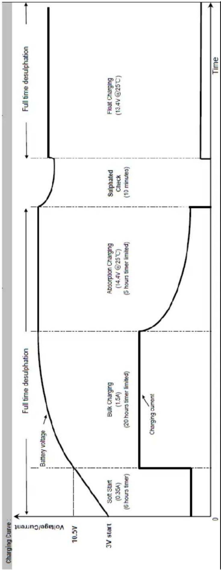
CHARGING STAGES
- SoftStart Mode: when battery voltage is below 10.5 volts due to deep discharge UNIT WILL ATTEMPT TO RECOVER IT. If successful unit will automatically switch to full power Constant Current mode. If if cannot, due to faulty shorted cell(s) it will shut down and indicate such. Battery MUST be REPLACED for both SAFETY as well as performance reasons.
- Constant Current: This stage recharges battery to 85% of its present capacity before automatically switching to Absorption stage.
- Absorption: completes the full charge before unit switches to Maintenance (aka Float) mode
- Maintenance (aka Float): keeps battery at full charge while continually desulfating it, ensuring full capacity for the longest possible life.
ADDITIONAL FEATURES
- Desulfation is the removal of sulfate build-up from your battery's plates. It occurs at all times the unit is connected.
- Short Circuit, Spark and Reverse Polarity Protection prevent the unit from having any output unless it is properly connected to your battery.
- Ambient Temperature Sensor (ATS-1), comes already installed on the Temperature Sensor input connector. Do not detach.
- Temperature Protection shuts down the unit if operating temperature is exceeded.
TABLE 4
VOLTAGE TABLE
MV: Minimum Voltage of a battery the unit will accept.
CV: Charge Voltage to move from Constant Current stage into Maintenance stage.
M: Voltage during the Maintenance stage.
| Model Battery Types MV CV | M | |||
| 1500 & 1510 | 12V Lead-Acid | 3.0V | 14.4V | 13.4V |
All readings must be taken at 77^ F ( 25^ C)
TROUBLESHOOTING
VDC Electronics Technical Support: (800) 379-5579 x6
- Unit does not have an output unless connected to a battery. In order to test the output using a meter, connect the meter to your battery. When you connect the unit, you will see the voltage rise.
- If the unit is not in maintenance after 72 hours (solid GREEN), check to make sure your battery meets the minimum voltage of 3.0 volts. Unit will not operate if battery is below the minimum voltage of 3.0 volts. If there is a load on your battery, disconnect it and charge again. If the problem persists, your battery may be shorted or too badly sulfated.
Visit our learning center at BatteryMINDers.com for additional battery information.
MAINTAINING MULTIPLE BATTERIES
Batteries should be charged individually. To properly maintain multiple batteries they should all be the same type (gel, flooded or AGM) and condition. It is OK to mix deep cycle and starter. Charge each battery individually before connecting together. Never connect batteries at different states of charge. The charged battery will rapidly transfer energy to the discharged battery possibly causing catastrophic failure. Once the batteries are charged, use 18 gauge or greater wire to connect the batteries or for greatest safety protection and ease of use, consider investing in the BatteryMINDer Y-Connector Model 210AY with SmarTECHnology*.
See diagram on the Page 13 for the most common multiple battery configuration.
You must connect multiple batteries of the same voltage, wire them in parallel (BatteryMINDer positive to positive A to positive B, BatteryMINDer negative to negative A to negative B).
If connecting 2 batteries of half your unit's voltage (example: 6V batteries on a 12V unit), wire them in series (BatteryMINDer positive to positive A, negative A to positive B, negative B to BatteryMINDer negative). When wired in series they act as one large system at the combined voltage (example: 6V+ 6V = 12V). You can connect these systems in a series parallel configuration in order to charge or maintain 4 or batteries in groups of 2.
*BatteryMINDer® has developed a simple, safe and inexpensive method of connecting multiple batteries they call SmarTECHnology®-Y. Using their single SmarTECHnology-Y connector, two batteries can be maintained simultaneously using just a single output charger designed to maintain batteries. Adding additional Y-connectors allows from four (4) to eight (8) batteries to be connected depending on the maintenance charger capability.

| FEATURES | |
| 1 | LED Indicators |
| 2 | A.C. Input plug |
| 3 | ATS-1 Ambient Temperature Sensor |
| 4 | Temperature Sensor input connector |
| 5 | Output cord with quick connect plug |
| 6A | Standard Battery Clip cord set with quick connector(Shown connected to output cord) (Model 1500) |
| 6B | Fully Insulated Battery Clip cord set (Aircraft-Grade) with 15A replaceable fuse assembly (Model 1510) |
| 7 | Permanent mounting tab + screw (optional) |
| 8 | Ring terminal assembly with 15A replaceable fuse (Model 1510) |
line
| Phase | Value | | ------------------------- | ----------- | | Soft Start | 0.35A | | Bulk Charging | 1.5A | | Bulk Charging | 20 hours timer limited || Safety & Protection | |
| Safety standards: | Complies with the requirements of the Standard(s) for Battery Chargers (UL-1236) and is identified with the ETL Listed Mark |
| EMC standard: FCC part15 | |
| Input-Output insulation test: | 1240Vac 60Hz5mAac, no breakdown |
| Cooling: By natural cooling | |
| Electrical Cable & Physical Parameters | ||
| Input socket UL 2 PIN wall mount | ||
| Output 1 | 10 feet 18AWG X2 105°C with quick connector + 2 feet 18AWG X2 with battery clamp; 2 feet 18AWG X2 with ring terminal (for 1510) | |
| Plastic enclosure dimension | 100 (L) x 65 (W) x 30 (H) mm | |
| 3.34 (L) x 2.56 (W) x 1.18 (H) in. | ||
| Operating temperature -10 to 40°C 14 to 104°F | ||
| Storage temperature | -25 to 85°C | -13 to 185°F |
| Operating humidity range | 0 to 90% RH | |
| Weight <1 lb. | ||
COMMON MULTIPLE BATTERY CONFIGURATIONS

12 VOLT PARALLEL

12 VOLT SERIES Using 6 Volt Batteries

12 VOLT (SERIES-PARALLEL) Using 6 Volt Batteries
FOR REPAIR OR REPLACEMENT
All returns must be authorized by VDC Electronics.
In the event that you believe your product may be defective, you MUST speak to a VDC Electronics technician at 1-800-379-5579 x6 (ET) before proceeding further.
NOTES
MODEL BatteryMINDer
□1500 or □Plus 1510
SERIAL NUMBER
PLACE OF PURCHASE
DATE OF PURCHASE
ALL returns must be authorized by VDC Electronics after speaking to a VDC Electronics technician at 800-379-5579 x6 (ET). Please see our “Repair or Replacement” section of this manual for additional information.
BatteryMINDER One-Year 100% Unconditional Money-Back GUARANTEE
This BatteryMINDer product is guaranteed to perform as claimed or WE will refund your full purchase price, including all taxes, shipping or handling cost applicable to the purchase.
Unit must be returned freight prepaid together with Proof of Purchase directly to VDC Electronics, Inc., NOT TO THE DEALER FROM WHICH IT WAS PURCHASED.
BatteryMINDer 1500 Five-Year Limited WARRANTY
VDC Electronics warrants this product for FIVE years from date of purchase at retail against defective material or workmanship and will be repaired or replaced at no charge. We make no warranty other than this limited warranty and expressly exclude any implied warranty including any warranty for consequential damages. This limited warranty is not transferable.
BatteryMINDer Plus 1510 TEN-Year Limited WARRANTY
VDC Electronics, Inc. warrants this product for TEN years from date of purchase at retail against defective material or workmanship and will be replaced with a new product equivalent or the Option to Upgrade at a discounted price. We make no warranty other than this limited warranty and expressly exclude any implied warranty including any warranty for consequential damages. This limited warranty is not transferable.
Unit must be returned freight prepaid together with Proof of Purchase directly to VDC Electronics, Inc., NOT TO THE DEALER FROM WHICH IT WAS PURCHASED.
IMPORTANT NOTICE
BatteryMINDer® Warranty Registration Reminder
Online Registration:
http://batteryminders.com/warranty_reg.php
Please register your unit online within 10 days of purchase. Due to the ever-changing technology associated with this BatteryMINDer® unit, we may be unable to keep you apprised of significant upgrades, changes, etc. without your registration. The information you provide upon registration will be used to keep a record of your purchase and will assist in providing support should you ever need to contact our Technical Service department:
techsupport@vdcelectronics.com; 800-379-5579 x6 (ET).


- both with SmarTECHnology®
- Volt 1500 mA
- Charger - Maintainer - Desulfator
- INCLUDES:
- \*CAUTION:
- READ AND SAVE THESE INSTRUCTIONS
- TABLE of CONTENTS
- REQUIRED IMPORTANT SAFETY INSTRUCTIONS WARNING
- TO REDUCE THE RISK OF FIRE, ELECTRIC SHOCK, OR INJURY TO PERSON, OBSERVE THE FOLLOWING:
- SAVE THESE INSTRUCTIONS
- WARNING – RISK OF EXPLOSIVE GASES
- PERSONAL PRECAUTIONS
- PREPARING TO CHARGE
- CHARGER LOCATION
- DC CONNECTION PRECAUTIONS
- FOLLOW THESE STEPS WHEN BATTERY IS INSTALLED IN VEHICLE. A SPARK NEAR BATTERY MAY CAUSE BATTERY EXPLOSION.
- TO REDUCE RISK OF A SPARK NEAR BATTERY:
- START-UP OPERATING INSTRUCTIONS
- CHARGING STAGES
- ADDITIONAL FEATURES
- VOLTAGE TABLE
- TROUBLESHOOTING
- VDC Electronics Technical Support: (800) 379-5579 x6
- MAINTAINING MULTIPLE BATTERIES
- FOR REPAIR OR REPLACEMENT
- BatteryMINDER One-Year 100% Unconditional Money-Back GUARANTEE
- BatteryMINDer 1500 Five-Year Limited WARRANTY
- BatteryMINDer Plus 1510 TEN-Year Limited WARRANTY
- IMPORTANT NOTICE
- BatteryMINDer® Warranty Registration Reminder
Brand : BatteryMINDer
Model : 1510
Category : Charger