Palladium - Weight bench True - Free user manual and instructions
Find the device manual for free Palladium True in PDF.


| Product Type | Weight Bench |
| Brand | True |
| Model | Palladium |
| Weight Capacity | 300 kg (661 lbs) |
| Dimensions (L x W x H) | 140 x 70 x 120 cm (55 x 27.5 x 47 in) |
| Product Weight | 35 kg (77 lbs) |
| Material | Steel frame, foam padding, vinyl upholstery |
| Adjustable Backrest | Yes, 7 positions from flat to 90° |
| Adjustable Seat | Yes, 3 positions |
| Leg Holders | Foam rollers for leg exercises |
| Transport Wheels | Yes, for easy movement |
| Power Source | None (manual exercise equipment) |
| Assembly Required | Yes, tools included |
| Cleaning | Wipe with damp cloth, mild soap; no abrasive cleaners |
| Safety Warnings | Maximum user weight 150 kg (330 lbs); use on level surface |
| Warranty | 2 years on frame, 1 year on upholstery |
| Spare Parts Availability | Contact True customer service for replacement parts |
Frequently Asked Questions - Palladium True
User questions about Palladium True
0 question about this device. Answer the ones you know or ask your own.
Ask a new question about this device
Download the instructions for your Weight bench in PDF format for free! Find your manual Palladium - True and take your electronic device back in hand. On this page are published all the documents necessary for the use of your device. Palladium by True.
USER MANUAL Palladium True
Palladium Strength Line
natural_image
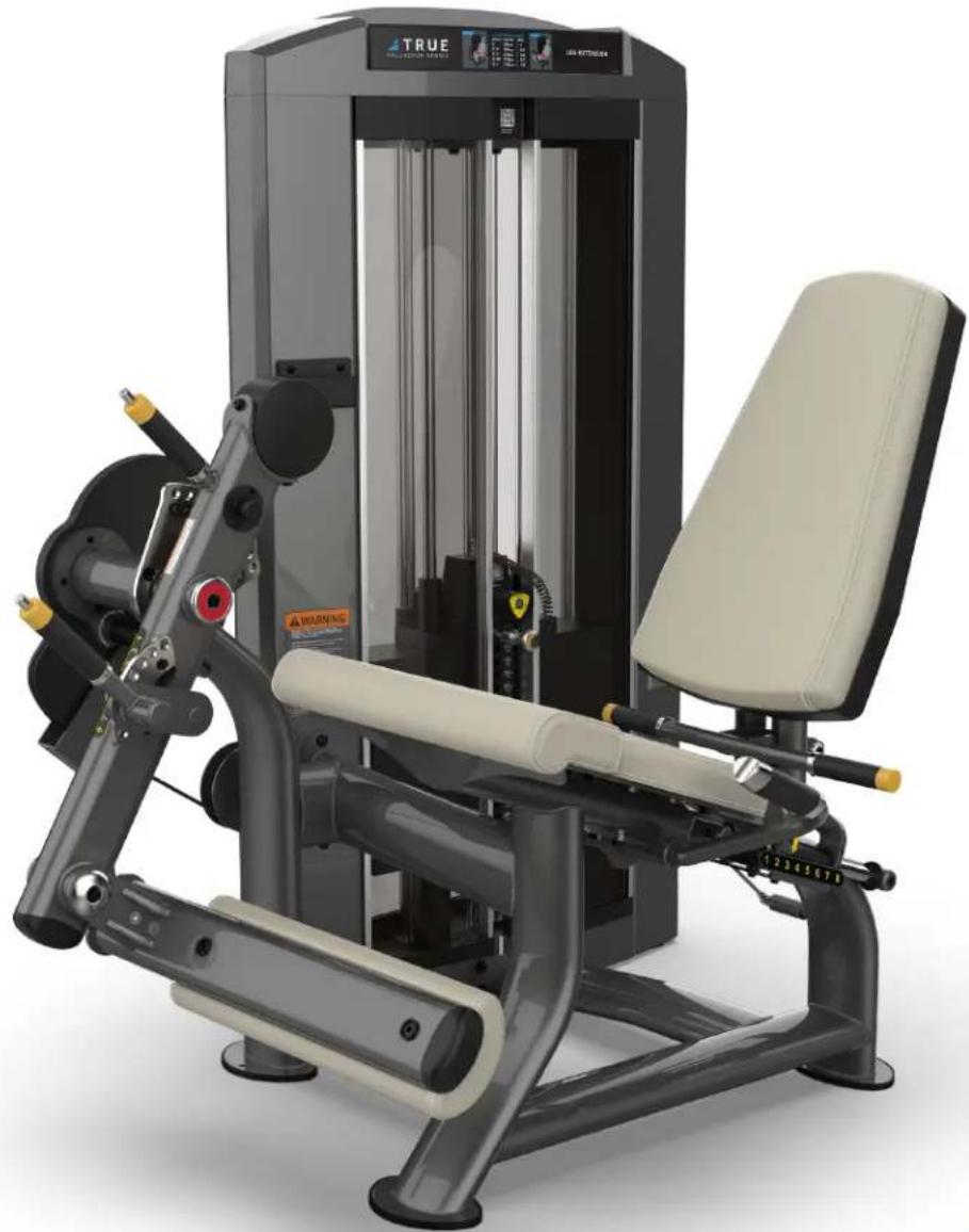
Modern fitness equipment with adjustable arm and seat, no visible text or symbols on the device itself.Note: SPL-0100 shown above, but this is the manual for all of the Palladium Strength line as the required assembly steps are the same for each machine.
Model # SPL-XXXX
Revision 072021
OWNER'S
MANUAL
IMPORTANT:
All products shown are prototype. Actual product delivered may vary.
Product specifications, features & software are subject to change without notice.
For the most up-to-date owner's manual please visit www.truefitness.com.
For documents in additional languages please visit www.truefitness.com/resources/document-library/
IMPORTANTE:
A MESSAGE TO OUR CUSTOMERS
Frank Trulaske began TRUE Fitness® over thirty-five year ago with the simple philosophy of delivering superior fitness products, service, and support. Today, TRUE is the global leader in premium fitness equipment for the commercial and residential markets. Our goal is to be the leader in technology, innovation, performance, safety and style. TRUE has received many awards for its product over the years and remains the benchmark for the industry. Fitness facilities and consumers invest in TRUE products for their durable commercial platforms used in all its products, both commercial and residential alike.
The proud manufacturing tradition of quality and the culture of innovation at TRUE have given rise to a full line of extraordinary cardio and strength equipment. As a result, people all over the world are benefiting from the TRUE experience. Innovation across the full product line has made TRUE successful and is a trademark of the TRUE heritage. TRUE's patented Heart Rate Control technology is just one of the remarkable ways we deliver simple and superior performance every user can enjoy, and most importantly, use to achieve personal health and fitness goals.
At the heart of our success is the relentless and systematic life testing of both our products and their components. We have dedicated employees who understand our philosophy is to deliver the best products in the world.
Our goal is to deliver the world's best premium equipment for our customers' health and fitness solutions.
Table of Contents
CHAPTER 1: SAFETY INSTRUCTIONS ....5
• COMMERICAL MAINTENANCE SCHEDULE 9
• COMPLIANCES....9
CHAPTER 2: ASSEMBLY GUIDE ....10
• MACHINE DIMENSIONS & WEIGHTS TABLE....10
WEIGHT STACK CONFIGURATION TABLE....11
• REQUIRED TOOLS....12
LABELS....12
WEIGHT AND SHROUD ASSEMBLY STEPS....15
CHAPTER 3: CARE & MAINTENANCE....28
CARE & MAINTENANCE....28
• DAILY INSPECTION & MAINTENANCE....28
• WEEKLY INSPECTION & MAINTENANCE....28
• OTHER SCHEDULED PREVENTIVE MAINTENANCE 29
• CLEANING THE EQUIPMENT ....29
CABLE INSPECTION & MAINTENANCE....30
CHAPTER 4: CUSTOMER SERVICE....32
- CONTACTING SERVICE....32
• CONTACTING SALES....32
• REPORTING FREIGHT OR PARTS DAMAGE....33
CHAPTER 5: WARRANTY INFORMATION ....34
CHAPTER 1: SAFETY INSTRUCTIONS

FACILITY AND USER SAFETY PRECAUTIONS
-
Review and understand all of the warning labels affixed to this machine and on the facility safety sign.
-
Be certain that the machine operation is understood before it is used. Refer to the instructional procedure label affixed to the machine.
-
Make sure all users are properly trained on how to use this equipment. If this machine is being used in a commercial setting, end users may not have access to this owners manual. It is the responsibility of the facility to instruct users as to the proper usage of the equipment as well as making them aware of potential hazards. Maximum user weight is 300 lbs (136 kg) unless otherwise stated in the manual.
-
Use each machine only for the intended exercise. Do not allow anyone to invent exercises not included on the instructional procedure label or the intended use Label.
-
Do not modify the machine.
-
This equipment meets industry safety standards for stability when used for the intended exercise. Do not allow straps, resistance bands or other means to be attached to the framework of this machine to perform stretching or body weight exercises. This can result in machine instability and lead to serious crushing injuries.
-
Keep children away from this equipment. Adults should closely supervise use by teenagers.
-
It is recommended that users receive a thorough medical exam before commencing an exercise program. All medical issues should be reviewed to ensure that weight training will not aggravate pre-existing medical conditions.
-
If the machine appears damaged or inoperable, contact a facility staff member to place an "OUT OF ORDER, DO NOT USE" sign on the machine until it is repaired. Only use TRUE supplied replacement components to service this machine.
-
Instruct users not to wear loose or dangling clothes or have headphone wires hanging when using this equipment.
-
Do not attempt to free any jammed assemblies by yourself as this may cause injury.
-
On Plate Loaded and Free Weight machines:
12a. Use of spotter(s). Instruct users to seek the advice of the facility staff as to the appropriate use of spotters when lifting. More than one spotter may be required depending upon the amount of weight being lifted.
12b. Instruct users to load weight plates evenly and carefully to avoid tipping equipment and crushing injuries.
12c. If the machine is equipped with safety stops or catches, inspect them and verify their proper operation before use and make sure they are securely in place before using or exiting the machine. Be certain members are instructed on how to operate and adjust
CHAPTER 1: SAFETY INSTRUCTIONS
12d. This equipment is designed for standard olympic size weight plates with a 50mm bore (1.9").
12e. Do not exceed the maximum weight capacity of the machine. Maximum plate size is 45 lbs. (25 kg.).
- On Selectorized and Cable equipped machines:
13a. Do not allow users to perform any exercise by holding the end of the cable and/or the cable end fitting. Use only appropriate handles or attachments properly connected to the cable end.
13b. Do not high-pin or double-pin the weight stack. Do not allow the machine to be used if the top plate or weight stack is pinned in a raised position. Use an assistant and carefully return the machine to the proper position with the cap plate resting on the top weight. Inspect the entire length of the cable to ensure that it is properly seated in all of the pulley grooves.
13c. Do not allow the use of weight plates or dumbbells to be used as a means to add additional weight to the weight stacks. Use only the TRUE adder weight system specifically designed for the machine.

INSTALLATION SAFETY PRECAUTIONS
- Read this installation manual entirely before assembling this equipment.
- Verify that there is adequate space surrounding this piece of equipment for safe access and operation. Installation must meet ADA requirements for accessibility.
- Install this piece of equipment on a solid level surface that does not deviate more than 1/8" over a 10' distance (or as defined and required by local building and architectural codes.)
-
TRUE strongly recommends that all equipment be anchored to the floor to prevent movement and increase stability.
-
Due to the wide variation of flooring on which the unit can be installed, contact a qualified contractor to determine an appropriate fastening system for your floor.
- Use 3/8" diameter hardware (10 mm) to anchor the machine. Anchors should have a minimum pull out force of 220 lb (110 kg) for each position.
- When attaching the machine to the floor, if there is a gap between the machine foot and the floor, do not use the anchor to remove the gap as this can cause the machine frame to deform. Instead, place a shim between the bottom of the foot and the floor, then tighten the anchor.
-
Anchoring holes are provided on the feet of the frame. All anchoring locations must be used when anchoring the equipment to the floor.
-
DO NOT install any fitness equipment near a pool, hot tub or other damp locations. Corrosion caused by installation in these locations can lead to premature failure of components.
- Be sure all hardware is tight before using this machine.
- Some assembly materials may come preassembled in the carton. Refer to Chapter 2: Assembly Guide for instructions on disassembling assembly materials where appropriate before beginning assembly.
CHAPTER 1: SAFETY INSTRUCTIONS

MAINTENANCE SAFETY PRECAUTIONS
- Refer to the maintenance schedule table in this manual for when to perform maintenance.
-
Check the function of your machine DAILY by verifying the following:
-
If equipped with cables, inspect cables and end fittings for any signs of wear. Replace if worn, frayed, or damaged with TRUE replacement components.
- Verify that all adjustments are possible and carried out with ease. Make sure that each adjustment pin inserts completely into each position without binding.
- Verify that safety catches and stops are in proper working order and engaged.
- Verify that the exercise is performed smoothly, free of noise, and/or binding.
-
If equipped with a weight stack, verify that the proper weight selector pin is in place.
-
Check the function of your machine WEEKLY by verifying the following:
-
Nuts, Bolts, and Fasteners: check tightness weekly. If any hardware has become loose, retighten it, use Loctite™ Threadlocker 242, or both.
-
Frames and Lifting Arms: Inspect weekly for integrity and function. Replace any component at first signs of wear. Use only TRUE supplied components.
-
Replace any warning label at the first sign of wear. Labels and the facility safety sign may be obtained from TRUE.
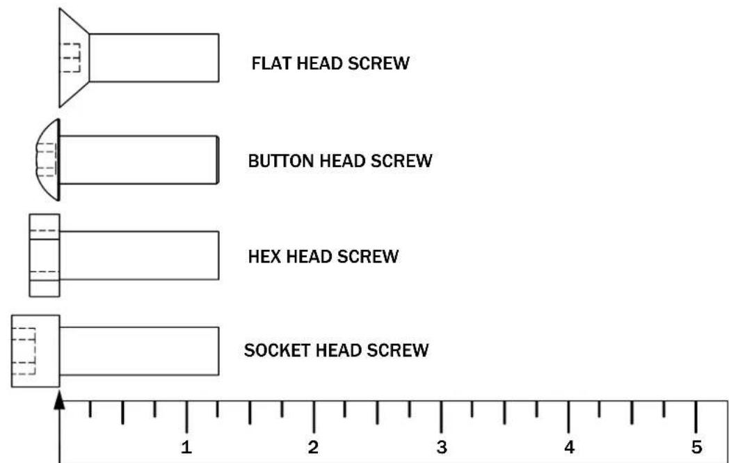
BOLT LENGTH MEASURING GUIDE
Page # 7 of 36
CHAPTER 1: SAFETY INSTRUCTIONS

IMPORTANT
Preventative maintenance is crucial to maintaining the function and safety of this equipment. Your facility must establish written guidelines for preventative maintenance and keep written or online records of the maintenance performed on these products. As a minimum, the items presented in the SAFETY section of this document and the items that follow here, should be included in your maintenance program.
- Cables (If equipped): inspect end fittings daily for wear. Inspect the entire length of the cable weekly. Replace cables at the first sign of wear and on an annual basis. If the cable tension has been adjusted, be certain that the cable nut is tight.
- Nuts, Bolts, and Fasteners: check tightness weekly. If any hardware has become loose, retighten and/or use Loctite™ brand Threadlocker 242. Be sure all hardware is tight before using the machine.
- Safety Catches: inspect catches, stop rods and their associated fasteners weekly. Tighten any loose hardware and replace any components at first signs of wear.
- Frames: sweat, disinfecting sprays and spills can lead to corrosion which may lead to premature failure of components. Wipe all machines down with a damp cloth and dry completely each day. This includes painted parts, chrome parts and upholstered pads.
- Painted and chrome plated parts: use Simple Green with a dilusion of 32:1 or similar cleaner for light dirt and grime. Use Turtle Wax Polishing Compound or a good car polish to remove heavier dirt and grease as well as for polishing. DO NOT use solvents, lacquer thinner, acetone or finger nail polish remover. For scuffs and marks that are not removed by the above methods use a soft scrub cleanser. Make sure all parts are dry upon completion.
- Weight stack enclosures (shrouds)(If Equipped): wipe down with a damp cloth as needed.
- Exercise instruction labels: clean with soap and water as needed.
- Guide rods (If equipped): wipe all dirt and dust from the guide rods before applying a light application of Tri-Flow ^TM or other teflon spray lubricant. Spray the Tri-Flow ^TM on a rag and then wipe the guide rods with the rag. DO NOT use oil lubricants such as WD-40. Caution: Tri-Flow ^TM will stain carpet and clothing.
- Bronze bushings: check monthly for signs of wear and replace as needed.
- Linear Bearing Shafts: wipe any accumulation of dust or other contaminants from the shafts on a weekly basis. Apply a thin layer of a Teflon® (PTFE) grease on a weekly basis. TRUE recommends Magnalube® brand.
- When replacing any component, use only TRUE supplied parts.
- Be sure all hardware is tight before using the machine.
Retain these instructions for future reference.
If you have any questions, do not hesitate to contact your TRUE dealer or TRUE Fitness Technology at (800)883-8783 or service@truefitness.com.
CHAPTER 1: SAFETY INSTRUCTIONS
| COMMERCIAL MAINTENANCE SCHEDULE | |||||
| DAILY | WEEKLY M | MONTHLY 6 M | MONTHS ANNUALLY | ||
| INSPECT: Cables for wear, tension, and proper connection if equipped. | X | ||||
| INSPECT: All nuts and bolts and tighten if needed. | X | ||||
| INSPECT: All anti-slip surfaces and replace as needed. | X | ||||
| INSPECT: All adjustment pins, weight stack pins, set screws, gas shocks, snap links, and pulleys if equipped. | X | ||||
| INSPECT: All accessory bars and handles. X | |||||
| INSPECT: All safety and instructional decals. | X | ||||
| INSPECT: All weight stack shields if equipped. | X | ||||
| CLEAN: Guide rods and lubricate with a teflon lubricant if equipped. | X | ||||
| CLEAN: Upholstery X | |||||
| LUBRICATE: Pivot bearings and linear bearings. | X | ||||
| REPLACE: Cables if equipped. X | |||||
COMPLIANCES:
This equipment complies with all fitness product standards. For a complete list of compliances, please visit www.TrueFitness.com.
CHAPTER 2: ASSEMBLY GUIDE
MACHINE DIMENSIONS & WEIGHTS:
| Dimensions (mm) Dimensions (in) | |||||||
| SKU # | Machine Description | Height | Width | Depth | Height | Width | Depth |
| SPL-0100 Leg | Extension 1478 | 1076.5 1363 | 58.2 42.4 53.7 | ||||
| SPL-0200 | Seated Leg Curl | 1478 | 1198 | 1496.98 | 58.2 | 47.2 | 58.9 |
| SPL-0300 | Leg Press | 1707.75 | 1168.82 | 2227.7 | 67.2 | 46.0 | 87.7 |
| SPL-0400 | Inner/Outer Thigh | 1478 | 1793 | 1016 58.2 | 70.6 40.0 | ||
| SPL-0500 | Triceps Extension | 1478 | 1206 | 1341 58.2 | 47.5 52.8 | ||
| SPL-0600 | Biceps Curl | 1478 | 1466 | 867 | 58.2 | 57.7 | 34.1 |
| SPL-0700 | Converging Shoulder Press | 1478 | 1524 | 1520 58.2 | 60.0 59.8 | ||
| SPL-0800 | Deltoid Raise | 1478 | 1243 | 994 | 58.2 | 48.9 | 39.1 |
| SPL-0900 | Converging Chest Press | 1874 | 1404 | 1000 73.8 | 55.3 39.4 | ||
| SPL-1000 | Pec Fly/Rear Delt | 1972 | 1360 | 1487 77.6 | 53.5 58.5 | ||
| SPL-1100 | Diverging Lat Pulldown | 1906 | 1315 | 1221 75.0 | 51.8 48.1 | ||
| SPL-1200 | Diverging Seated Row | 1478 | 1130 | 1606 58.2 | 44.5 63.2 | ||
| SPL-1300 | Low Back | 1478 | 1081 | 1405 | 58.2 | 42.6 | 55.3 |
| SPL-1400 | Abdominal | 1567 | 1530 | 1206 | 61.7 | 60.2 | 47.5 |
| SPL-1500 | Rotary Torso | 1478 | 1104 | 1320 | 58.2 | 43.5 | 52.0 |
| SPL-1600 | Calf Press | 1478 | 1157 | 1809 | 58.2 | 45.6 | 71.2 |
| SPL-1700 | Glute Press | 1478 | 1049 | 1137 | 58.2 | 41.3 | 44.8 |
| SPL-1800 | Horizontal Leg Curl | 1478 | 1037 | 1621 58.2 | 40.8 63.8 | ||
| SPL-2000 | Hip Thrust | 1534 | 1256 | 1573 | 60.4 | 49.4 | 61.9 |
CHAPTER 2: ASSEMBLY GUIDE
WEIGHT STACK CONFIGURATION:
| Number of Weight Plates N | Number of Bumpers | Top Cap | Shroud SKU #s | Rep Counter | |||||||
| SKU # | Machine Description | Light (L) | Standard | Heavy (H) | Light (L) | Standard | Heavy (H) | Acrylic Steel | |||
| SPL-0100 | Leg Extension 12 | 16 20 | 6 4 2 | SPL-00-TPL100X | SPLSRDPS | SPLSRDMS | SPLCTR | ||||
| SPL-0200 | Seated Leg Curl | 12 16 | 20 6 4 2 | SPL-00-TPL100X | SPLSRDPS | SPLSRDMS | |||||
| SPL-0300 | Leg Press | N/A | N/A | 24 | N/A | N/A | 2 | SPL-03-TPL100X | SPLSRDPT | SPLSRDMT | |
| SPL-0400 | Inner/Outer Thigh | 12 16 | 20 6 4 2 | SPL-00-TPL100X | SPLSRDPS | SPLSRDMS | |||||
| SPL-0500 | Triceps Extension | 12 16 | 20 6 4 2 | SPL-05-TPL100X | SPLSRDPS | SPLSRDMS | |||||
| SPL-0600 | Biceps Curl | 12 16 | 20 6 4 2 | SPL-00-TPL100X | SPLSRDPS | SPLSRDMS | |||||
| SPL-0700 | Converging Shoulder Press | 12 16 | 20 6 4 2 | SPL-00-TPL100X | SPLSRDPS | SPLSRDMS | |||||
| SPL-0800 | Deltoid Raise | 12 16 | 20 6 4 2 | SPL-00-TPL100X | SPLSRDPT | SPLSRDMT | |||||
| SPL-0900 | Converging Chest Press | 12 16 | 20 6 4 2 | SPL-00-TPL100X | SPLSRDPS | SPLSRDMS | |||||
| SPL-1000 | Pec Fly/Rear Delt | 12 16 | 20 6 4 2 | SPL-00-TPL100X | SPLSRDPS | SPLSRDMS | |||||
| SPL-1100 | Diverging Lat Pulldown | 12 16 | 20 6 4 2 | SPL-00-TPL100X | SPLSRDPT | SPLSRDMT | |||||
| SPL-1200 | Diverging Seated Row | 12 16 | 20 6 4 2 | SPL-00-TPL100X | SPLSRDPS | SPLSRDMS | |||||
| SPL-1300 | Low Back 12 | 16 20 6 4 | 2 | SPL-00-TPL100X | SPLSRDPT | SPLSRDMT | |||||
| SPL-1400 | Abdominal | 12 16 | 20 6 4 2 | SPL-00-TPL100X | SPLSRDPT | SPLSRDMT | |||||
| SPL-1500 | Rotary Torso | 12 16 20 | 20 6 4 2 | SPL-00-TPL100X | SPLSRDPT | SPLSRDMT | |||||
| SPL-1600 | Calf Press | 12 16 | 20 6 4 2 | SPL-00-TPL100X | SPLSRDPT | SPLSRDMT | |||||
| SPL-1700 | Glute Press | 12 16 | 20 6 4 2 | SPL-00-TPL100X | SPLSRDPT | SPLSRDMT | |||||
| SPL-1800 | Horizontal Leg Curl | 12 16 | 20 6 4 2 | SPL-00-TPL100X | SPLSRDPT | SPLSRDMT | |||||
| SPL-1900 | Weight Assisted Chin Dip | 12 16 | 20 6 4 2 | SPL-00-TPL100X | SPLSRDPT | SPLSRDMT | |||||
| SPL-2000 | Hip Thrust | 12 16 | 20 6 4 2 | SPL-00-TPL100X | SPLSRDPS | SPLSRDMS | |||||
CHAPTER 2: ASSEMBLY GUIDE
REQUIRED TOOLS:
 | Flat Head Screwdriver |
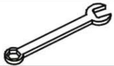 | Open Ended wrench |
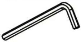 | Allen wrench:• 3/32”• 5/32”• 3/16” |
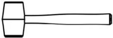 | Rubber Mallet |
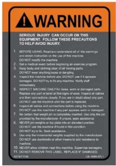
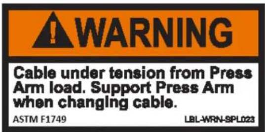
LABELS:
| TRUE |
| TRUE FITNESS TECHNOLOGY, INC865 HOFF RD, ST LOUIS MISSOURI 63366 USA |
| MODEL NO: SPL0100 |
| SERIAL NO: 19-SPL010001A |
| WARNING | |
| SUPPORT WEIGHT OF SEAT BY GRASPING HANDLE BEFORE ADJUSTING SEAT POSITION. | |
| ASTM F1748 | PIN B2003 |
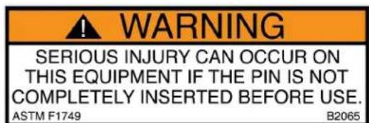
| WARNING | |
| DAMAGE TO MACHINE WILL OCCUR IF KNOB IS ADJUSTED WHILE USING MACHINE. | |
| ASTM F1749 | URL:MRN-SPL082 |

CHAPTER 2: ASSEMBLY GUIDE
LABELS:
Weight Stack Label
Part Number:
LBL-WS-SPL190
| 10 LBS. | 4.5 KG. |
| 25 LBS. | 11.3 KG. |
| 40 LBS. | 18.1 KG. |
| 55 LBS. | 24.9 KG. |
| 70 LBS. | 31.8 KG. |
| 85 LBS. | 38.6 KG. |
| 100 LBS. | 45.4 KG. |
| 115 LBS. | 52.2 KG. |
| 130 LBS. | 59.0 KG. |
| 145 LBS. | 65.8 KG. |
| 160 LBS. | 72.6 KG. |
| 175 LBS. | 79.4 KG. |
| 190 LBS. | 86.2 KG. |
Weight Stack Label Part Number: LBL-WS-SPL250
| 10 LBS. | 4.5 KG. |
| 25 LBS. | 11.3 KG. |
| 40 LBS. | 18.1 KG. |
| 55 LBS. | 24.9 KG. |
| 70 LBS. | 31.8 KG. |
| 85 LBS. | 38.6 KG. |
| 100 LBS. | 45.4 KG. |
| 115 LBS. | 52.2 KG. |
| 130 LBS. | 59.0 KG. |
| 145 LBS. | 65.8 KG. |
| 160 LBS. | 72.6 KG. |
| 175 LBS. | 79.4 KG. |
| 190 LBS. | 86.2 KG. |
| 205 LBS. | 93.0 KG. |
| 220 LBS. | 99.8 KG. |
| 235 LBS. | 106.6 KG. |
| 250 LBS. | 113.4 KG. |
Weight Stack Label Part Number: LBL-WS-SPL310
| 10 LBS. | 4.5 KG. |
| 25 LBS. | 11.3 KG. |
| 40 LBS. | 18.1 KG. |
| 55 LBS. | 24.9 KG. |
| 70 LBS. | 31.8 KG. |
| 85 LBS. | 38.6 KG. |
| 100 LBS. | 45.4 KG. |
| 115 LBS. | 52.2 KG. |
| 130 LBS. | 59.0 KG. |
| 145 LBS. | 65.8 KG. |
| 160 LBS. | 72.6 KG. |
| 175 LBS. | 79.4 KG. |
| 190 LBS. | 86.2 KG. |
| 205 LBS. | 93.0 KG. |
| 220 LBS. | 99.8 KG. |
| 235 LBS. | 106.6 KG. |
| 250 LBS. | 113.4 KG. |
| 265 LBS. | 120.2 KG. |
| 280 LBS. | 127.0 KG. |
| 295 LBS. | 133.8 KG. |
| 310 LBS. | 140.6 KG. |
Weight Stack Label Part Number: LBL-WS-SPL419
| 11 LBS. | 5.0 KG. |
| 28 LBS. | 12.7 KG. |
| 45 LBS. | 20.4 KG. |
| 62 LBS. | 28.1 KG. |
| 79 LBS. | 35.8 KG. |
| 96 LBS. | 43.5 KG. |
| 113 LBS. | 51.3 KG. |
| 130 LBS. | 59.0 KG. |
| 147 LBS. | 66.7 KG. |
| 164 LBS. | 74.4 KG. |
| 181 LBS. | 82.1 KG. |
| 198 LBS. | 89.8 KG. |
| 215 LBS. | 97.5 KG. |
| 232 LBS. | 105.2 KG. |
| 249 LBS. | 112.9 KG. |
| 266 LBS. | 120.7 KG. |
| 283 LBS. | 128.4 KG. |
| 300 LBS. | 136.1 KG. |
| 317 LBS. | 143.8 KG. |
| 334 LBS. | 151.5 KG. |
| 351 LBS. | 159.2 KG. |
| 368 LBS. | 166.9 KG. |
| 385 LBS. | 174.6 KG. |
| 402 LBS. | 182.3 KG. |
| 419 LBS. | 190.1 KG. |
CHAPTER 2: ASSEMBLY GUIDE
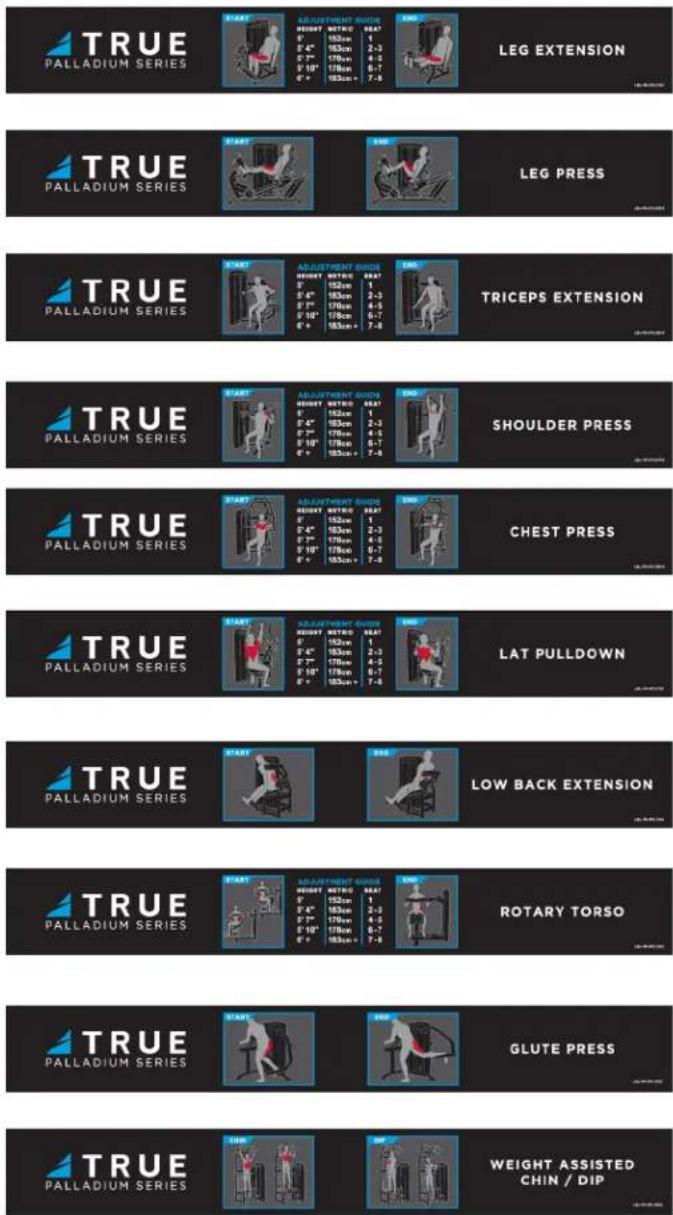
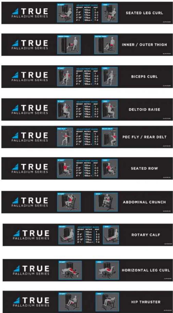
WORKOUT PLACARDS:
CHAPTER 2: ASSEMBLY GUIDE
ASSEMBLY STEPS:
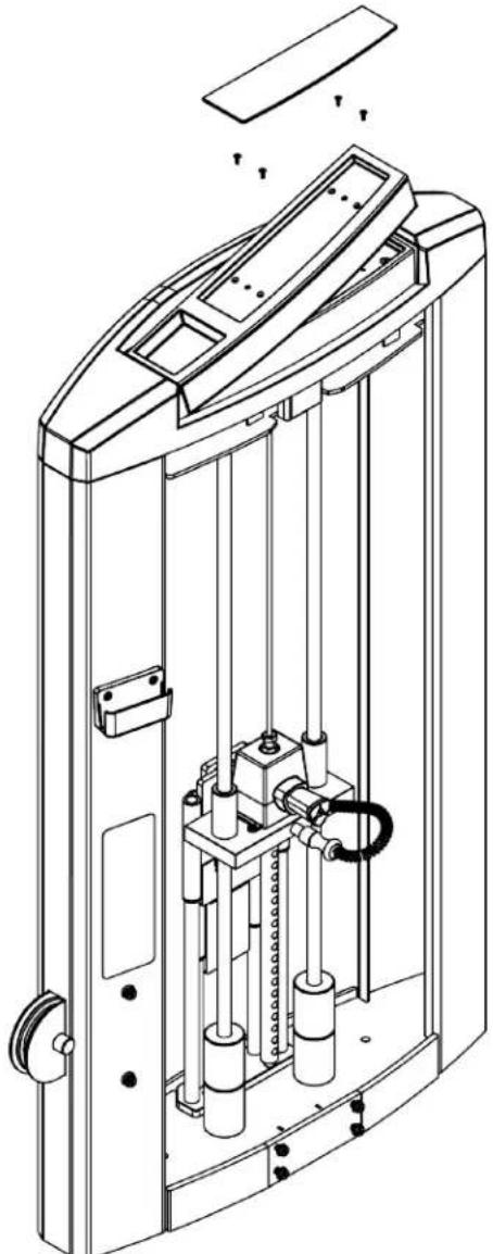
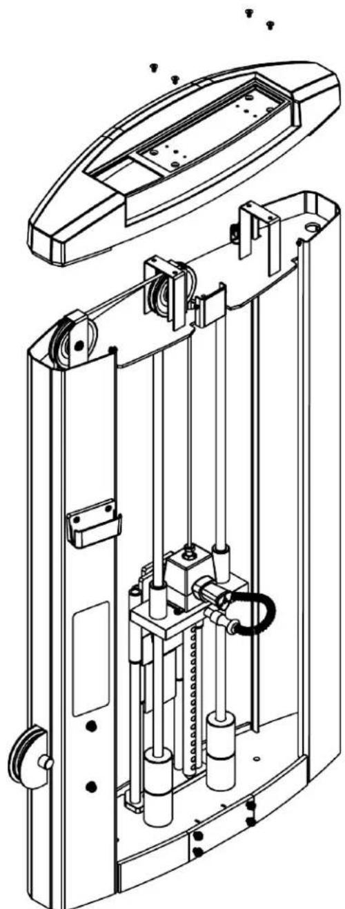
Step 1 (Top Cap Tray):
Remove the fully assembled machine from the pallet and place in the final resting location.
Remove the Top Cap Tray from the Top Cap by removing the Top Cap Pad and Top Cap Tray Screws.
Note: Angle the Top Cap Tray as shown for proper removal.

CAUTION: All images are shown without the Mainframe attached to the Upright Assembly for illustration ty. Do not attempt to assemble the Front or Rear Shrouds without the Upright Assembly secured to the nframe.
natural_image
Technical line drawing of a mechanical device with internal components and mounting holes (no text or symbols)CHAPTER 2: ASSEMBLY GUIDE
ASSEMBLY STEPS:
Step 2 (Top Cap):
Remove the Top Cap Screws from the Top Cap.
Carefully remove the Top Cap from the Upright Assembly so as not to damage the Top Cap that is tightly fitted to the Upright Assembly.
natural_image
Technical line drawing of a mechanical device with internal components and mounting holes (no text or symbols)CHAPTER 2: ASSEMBLY GUIDE
ASSEMBLY STEPS:
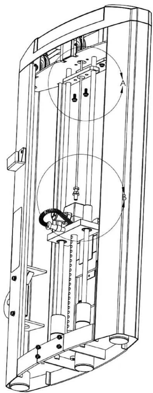
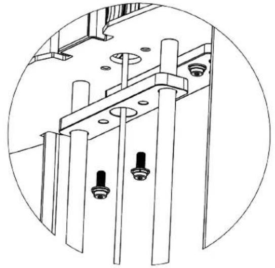
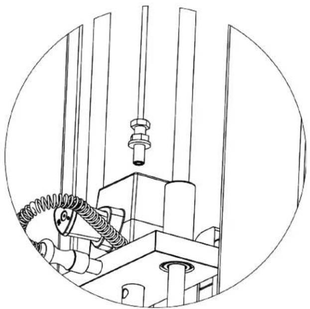
Step 3 (Guide Rods and Weight Stack Cable):
Remove the Guide Rod Bracket from the Upright Assembly by removing the Guide Rod Bracket screws.
Remove the Cable Bolt attached to the Weight Stack Cable from the Weight Stack Top Plate.
natural_image
Technical line drawing of a mechanical lifting device with internal components and motion arrows (no text or symbols)DETAIL A
natural_image
Technical line drawing of a mechanical assembly with bolts and rods (no text or symbols)DETAIL B
natural_image
Technical line drawing of a mechanical assembly with pipes and a bolt, enclosed in a circular frame (no text or symbols)CHAPTER 2: ASSEMBLY GUIDE
ASSEMBLY STEPS:
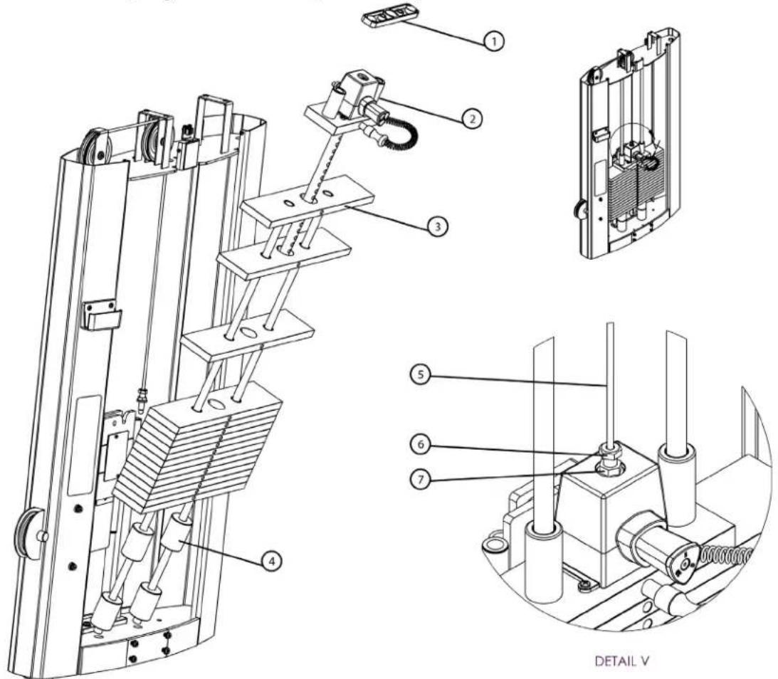
Step 4A (Weight Stack Configuration):
Angle the Guide Rods outward and then remove the Guide Rod Bracket and Weight Stack Top Plate.
Referring to the Weight Stack Configuration table on pg. 11, place the selected combination of Weight Stack Plates and Bumpers onto the Guide Rods. Discard extra Bumpers.
Place the Weight Stack Top Plate and Guide Rod Bracket onto the Guide Rods. Route the Weight Stack Cable through the Guide Rod Bracket and secure the Cable Bolt to the Weight Stack Top Plate referring to Cable Tension on pg. 31. Tighten the Cable Nut on the Weight Stack Top Plate. Using the hardware from Step 3, secure the Guide Rod Bracket to the Upright Assembly.
| Item Description |
| 1 Guide Rod Bracket |
| 2 Weight Stack Top Plate |
| 3 Weight Stack Plate |
| 4 Weight Stack Bumper |
| 5 Weight Stack Cable |
| 6 Cable Bolt |
| 7 Cable Nut |
Lubricate the Guide Rods per guidelines in Chapter 1: Safety Instructions.
CHAPTER 2: ASSEMBLY GUIDE
ASSEMBLY STEPS:
Step 4B (Weight Stack Label):
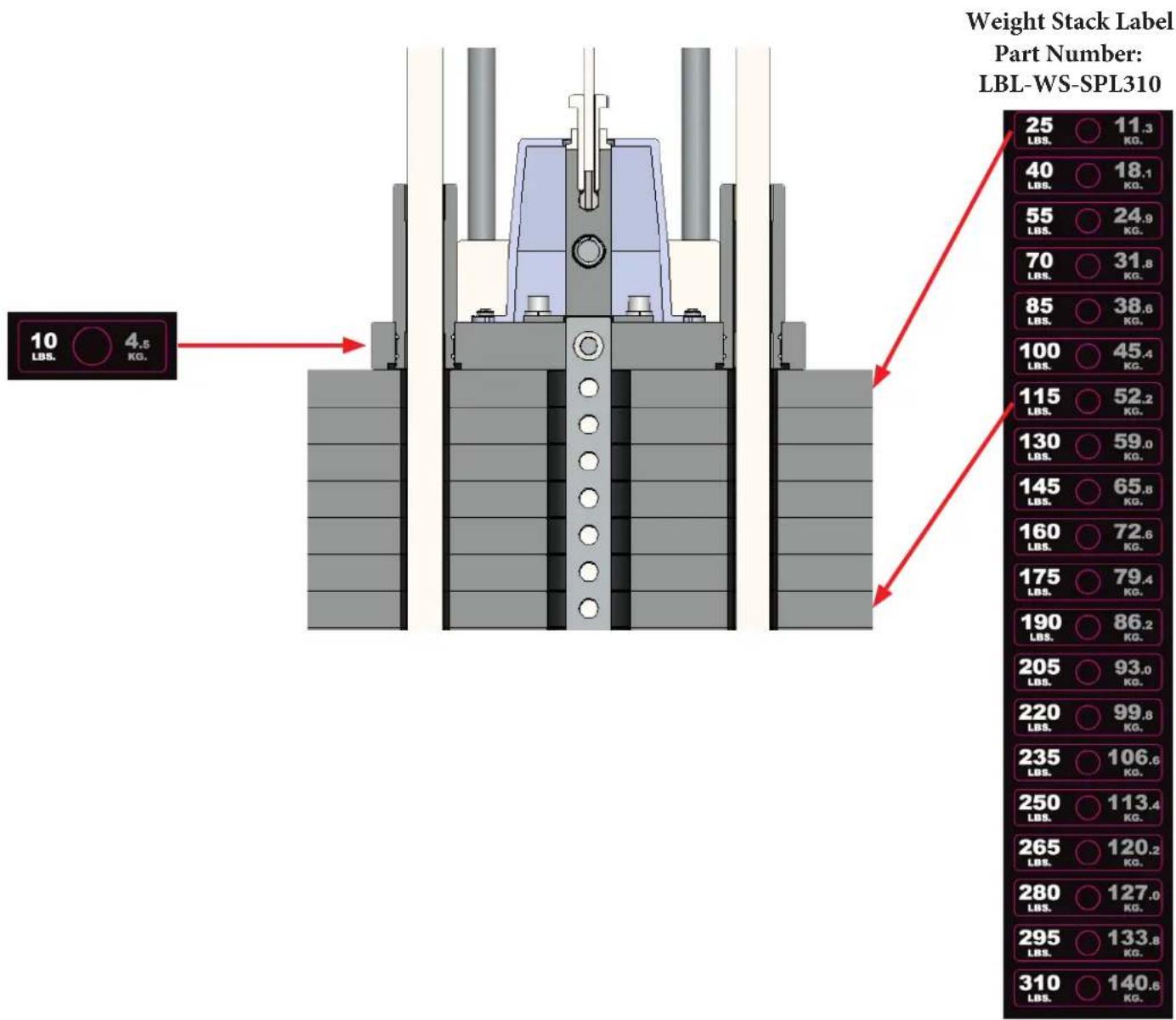
To ensure a proper fit to the weight plates, the weight stack label must be secured in two steps.
First, cut the top portion (10 lbs/4.5 kg.) from the weight stack label and secure that to the weight stack top plate.
Lastly, secure the remaining portion of the weight stack label to the weight stack starting with the top weight plate located under the weight stack top plate.
other
| Weight Stack Label | Part Number | | ----------------- | ----------- | | 25 LBS. | 11.3 KG | | 40 LBS. | 18.1 KG | | 55 LBS. | 24.9 KG | | 70 LBS. | 31.8 KG | | 85 LBS. | 38.6 KG | | 100 LBS. | 45.4 KG | | 115 LBS. | 52.2 KG | | 130 LBS. | 59.0 KG | | 145 LBS. | 65.8 KG | | 160 LBS. | 72.6 KG | | 175 LBS. | 79.4 KG | | 190 LBS. | 86.2 KG | | 205 LBS. | 93.0 KG | | 220 LBS. | 99.8 KG | | 235 LBS. | 106.6 KG | | 250 LBS. | 113.4 KG | | 265 LBS. | 120.2 KG | | 280 LBS. | 127.0 KG | | 295 LBS. | 133.8 KG | | 310 LBS. | 140.6 KG |CHAPTER 2: ASSEMBLY GUIDE
ASSEMBLY STEPS:
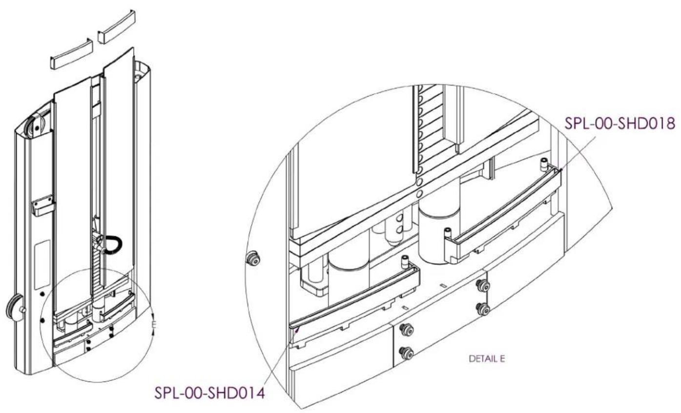
Step 5 (Front Acrylic Shrouds):
Insert the Front Shroud Bottom Retaining Caps into the designated slots on the Upright Assembly.
Note: The Front Shroud Bottom Retaining Caps are left (Part Number SPL-00-SHD014) and right (SPL-00-SHD018) dependent.
CHAPTER 2: ASSEMBLY GUIDE
ASSEMBLY STEPS:
Step 6 (Front Acrylic Shrouds):
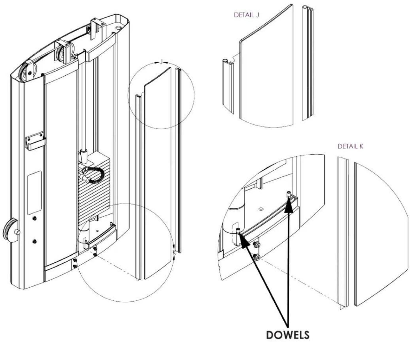
Remove the protective wrapping from the Front Shrouds.
Slide the channels onto the Front Shroud as shown below in Detail J.
Slide the Front Shrouds onto the Front Shroud Bottom Retaining Caps. Note: Confirm the two dowels on the Front Shroud Bottom Retaining Cap are inserted into the channels to secure the channels and shrouds in place.
CHAPTER 2: ASSEMBLY GUIDE
ASSEMBLY STEPS:
Step 7 (Front Acrylic Shrouds):
Slide the Front Shroud Top Retaining Caps onto the Front Shrouds. Confirm the two dowles on each of the Front Shroud Top Retaining Caps are inserted into the extrusions on the Upright Assembly as shown below.
Secure both Front Shroud Top Retaining Caps using the identified hardware already attached to the Upright Assembly.
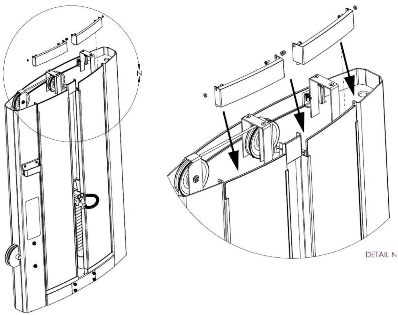
DETAIL N
CHAPTER 2: ASSEMBLY GUIDE
ASSEMBLY STEPS:
Step 8 (Rear Acrylic Shrouds):
Insert the Rear Shroud Bottom Retaining Cap into the designated slots on the Upright Assembly.
Remove the protective wrapping from the Rear Shroud.
Slide the channels onto the Rear Shroud.
Slide the Rear Shroud onto the Rear Shroud Bottom Retaining Cap.
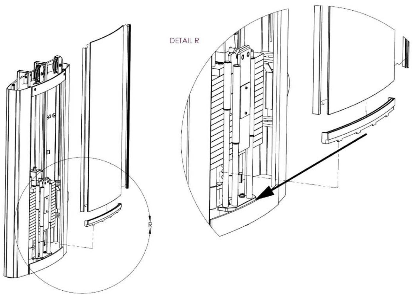
CHAPTER 2: ASSEMBLY GUIDE
ASSEMBLY STEPS:
Step 9 (Rear Acrylic Shrouds):
Position the Rear Shroud Top Retaining Cap onto the Rear Shroud as shown below.
Secure the Rear Shroud Top Retaining Cap using the identified hardware already attached to the Upright Assembly.
Starting with Step 3 (Guide Rods and Weight Stack Cable) and ending with Step 1 (Top Cap Tray), secure the Top Cap Assembly to the Upright Assembly.
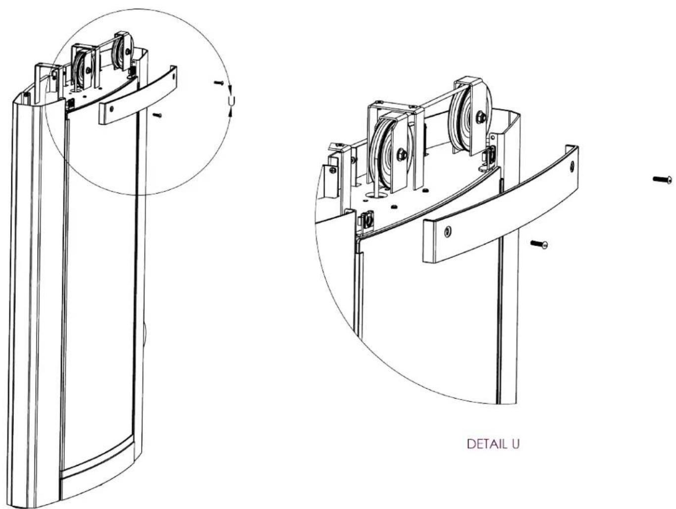
natural_image
Technical line drawing of a mechanical device with two views: top shows a cylindrical component, bottom shows a curved mechanical assembly with pulleys and bolts (no text or symbols)CHAPTER 2: ASSEMBLY GUIDE
ASSEMBLY STEPS:
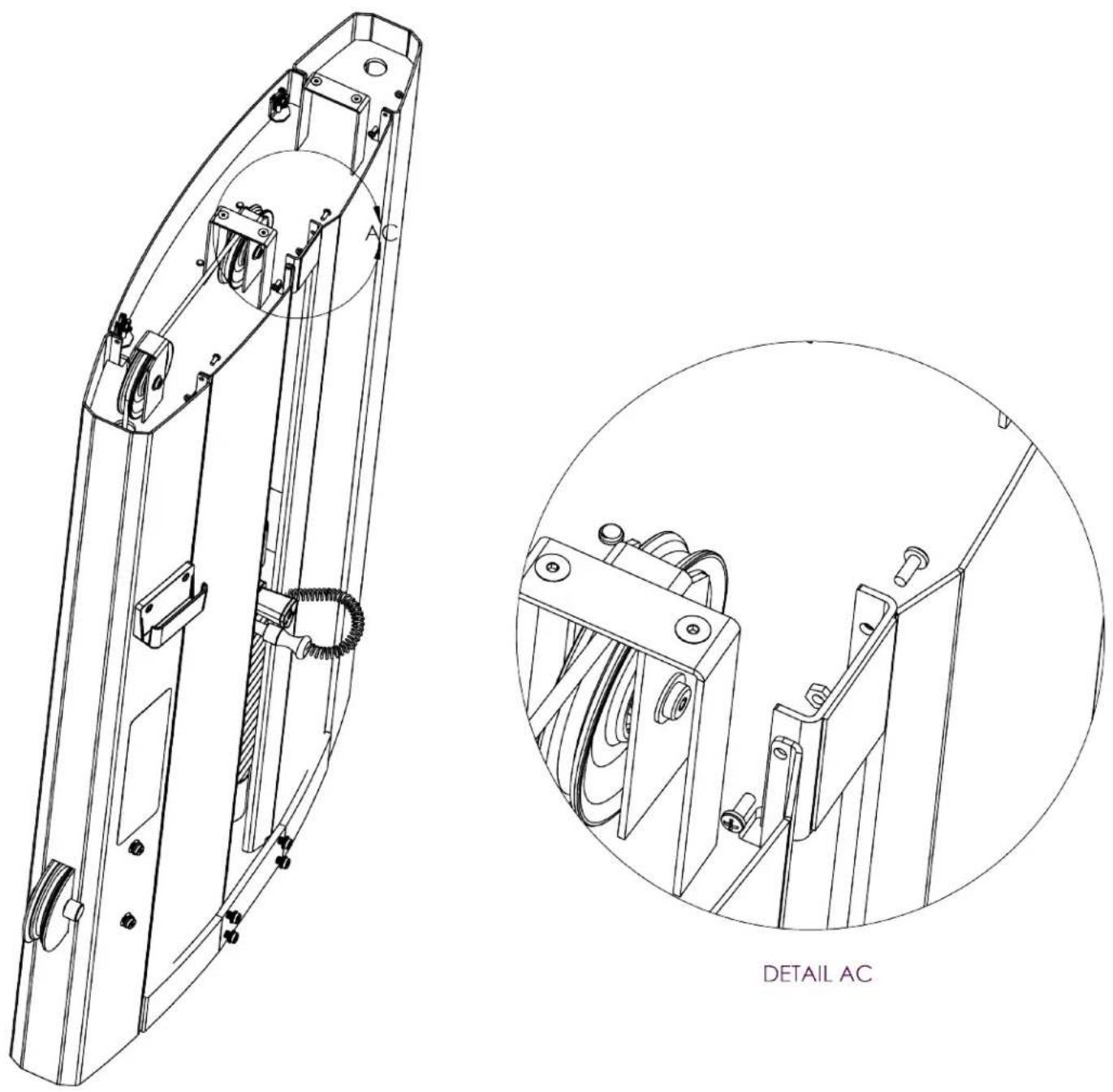
Step 10 (Front Metal Shrouds):
Slide the Front Shrouds onto the Upright Assembly.
Note: Confirm the three metal tabs on each Front Shroud are inserted into the Upright Assembly as shown to secure the shrouds in place.
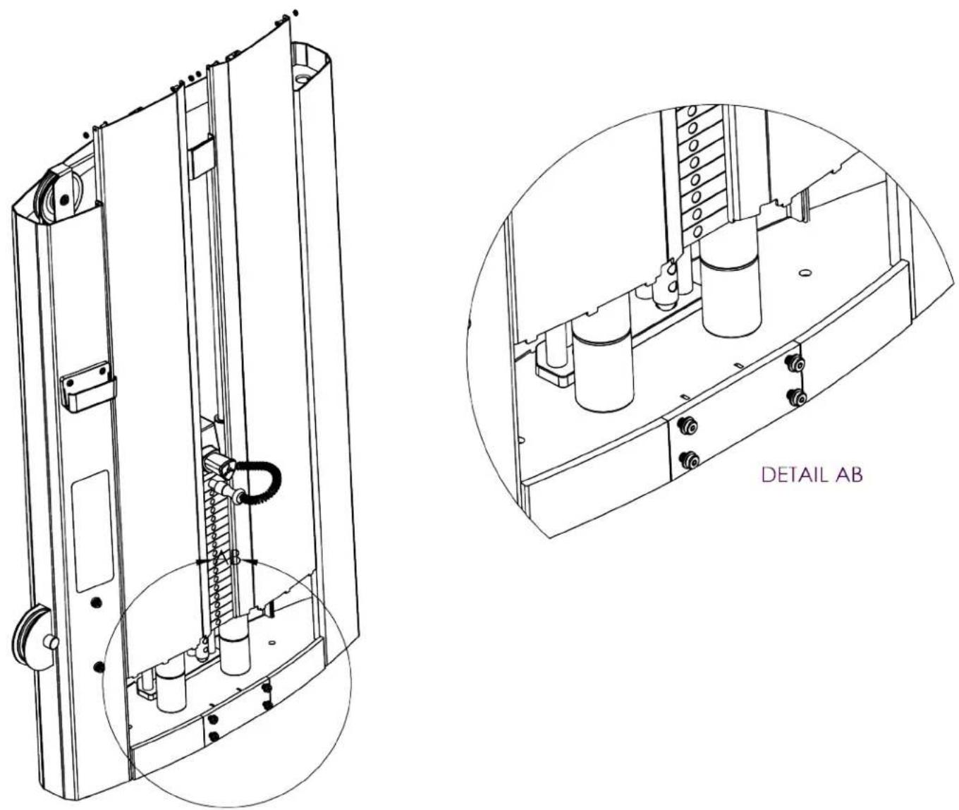
CHAPTER 2: ASSEMBLY GUIDE
ASSEMBLY STEPS:
Step 11 (Front Metal Shrouds):
Secure both Front Shrouds using the identified hardware already attached to the Upright Assembly.
CHAPTER 2: ASSEMBLY GUIDE
ASSEMBLY STEPS:
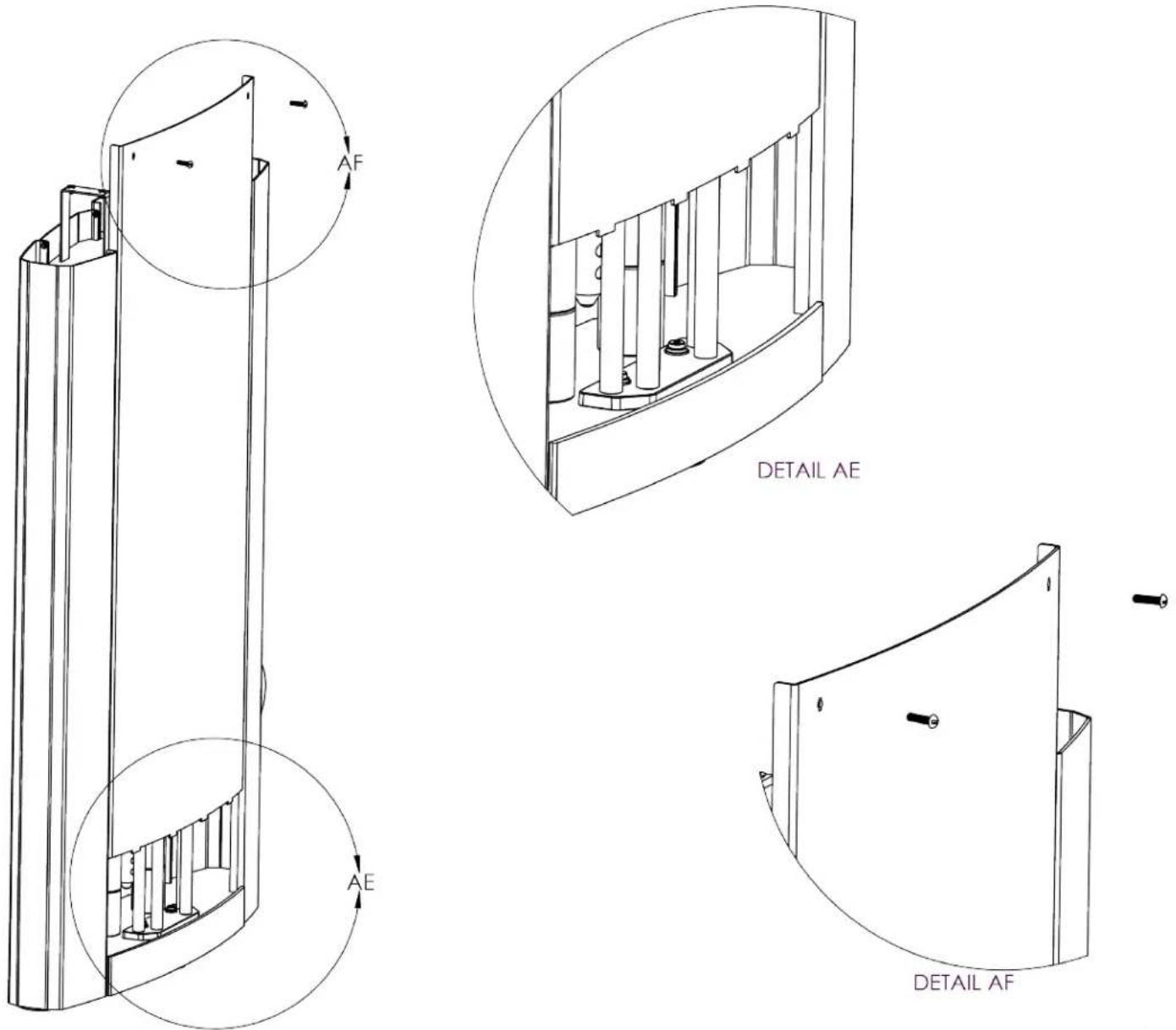
Step 12 (Rear Metal Shroud):
Slide the Rear Shroud onto the Upright Assembly as shown below. Note: Confirm the four metal tabs on the Rear Shroud are inserted into the Upright Assembly as shown to secure the shroud in place.
Secure the Rear Shroud using the identified hardware already attached to the Upright Assembly.
Starting with Step 3 (Guide Rods and Weight Stack Cable) and ending with Step 1 (Top Cap Tray), secure the Top Cap Assembly to the Upright Assembly.
CHAPTER 3: CARE & MAINTENANCE
CARE & MAINTENANCE:
Preventative maintenance is crucial to maintaining the function and safety of this equipment. Your facility must establish written guidelines for preventative maintenance and keep written or online records of the maintenance performed on these products. As a minimum, the items presented in the Safety Instructions section of this document and the items that follow here, should be included in your maintenance program.
IMPORTANT: Always purchase replacement parts from TRUE Fitness. Many parts are tested and manufactured specifically for TRUE Fitness equipment. Use of unapproved parts may cause serious injury and/or void the limited warranty.
DAILY INSPECTION&MAINT'EMANCE:
The following items are critical to the safety of users and maintenance staff as well as ensuring the optimum performance of the machines. These inspections should be performed each day before the equipment is subject to use. TRUE Fitness is not responsible for performing or scheduling regular maintenance or inspections.
- Inspect cables for wear, tension, and proper connection (as described in the cable inspection section below) if equipped.
- Inspect all adjustment pins, weight stack pins, set screws, gas shocks, snap links, and pulleys if equipped.
- Inspect all safety and instructional decals.
- Inspect all weight stack shields if equipped.
- Verify that rubber hand grips are intact and secure.
- Verify that anti-skid foot grips are intact and secure
- Verify that the weight stack selector pin is attached with the coiled lanyard to the top plate if equipped.
WEEKLY INSPECTION&MAINTENANCE:
The following items are critical to the safety of users and maintenance staff as well as ensuring the optimum performance of the machines. These inspections should be performed each week. TRUE Fitness is not responsible for performing or scheduling regular maintenance or inspections.
- Check entire length of cable & end fittings for any signs of wear if equipped. Replace immediately as required. (Refer to Daily Maintenance Section).
- Verify that a minimum of 1/2 inch (12.7mm) of the threaded portion of the cable bolt is threaded into the top plate and that the nut is tight if equipped with a cable. (See Cable Inspection & Maintenance Section).
- Perform a function test by placing the selector pin in the top plate and cycling the machine through the intended motion if equipped with a cable. Verify that the machine operates smoothly without binding. Select a moderate weight and repeat.
- Verify that each pulley rotates freely when performing the exercise if equipped with pulleys. A pulley that does not rotate will cause extreme cable wear and could lead to cable failure. Determine cause and remedy immediately.
- Verify that the adjustment pop pins retract easily and fully engage (when released) into each adjustment disc hole/slot. The pop pins are spring loaded so they should return to the engaged position when you release the knob.
- Verify that the adjustment pin disengages and engages freely when actuating the adjustment mechanism. Be sure that the adjustment pin inserts fully into the adjustment disc.
- Verify that all hardware is tight and that associated frame members are secure. Apply a few small drops of a thread locking compound such as Loctite on any loose bolts.
- Inspect frame for integrity and function. Replace any components at the first sign of wear with only TRUE supplied parts.
CHAPTER 3: CARE & MAINTENANCE
OTHER SCHEDULED PREVENTIVE MAINTENANCE:
TRUE recommends that scheduled maintenance be performed by a qualified service technician. Please contact your dealer or visit www.truefitness.com to contact a local TRUE authorized service technician.
Monthly:
Clean guide rods and lubricate with a Teflon grease if equipped with guide rods.
Every 6 months:
Lubricate pivot bearing and linear bearings with lithium grease.
CLEANING THE EQUIPMENT:
Daily Cleaning:
Wipe all machines with a water dampened cloth and dry completely. This includes painted parts, chrome plated parts (except guide rods), plastic parts, and upholstered pads. It is important not to leave parts damp. This will increase the potential for corrosion to occur.
CAUTION:
Certain anti-bacterial cleaners and other harsh cleaning agents can induce corrosion on the machine components. These solutions can also dry out and cause cracking and splitting on the upholstery.
Heavy Duty Cleaning:
Guide Rods (If Equipped): Clean and lubricate with a Teflon Spray. Be sure to coat the entire guide rod. Spraying lubricant into the cap plate bushings is also recommended.
Chromed Adjustment Tubes: Wipe away dust and dirt before applying a Teflon spray lubricant. TRUE Fitness recommends using TriFlow or a similar brand.
Linear Bearings: Clean the linear shaft and lubricate (as required) with Teflon based grease. Keeping linear bearings clean and lubricated is critical to long life and good performance.
Painted Frames: If you have scuff marks, grease or a heavy dirt buildup on frame components, start with a mild soap solution or a diluted solution of a product such as Simple Green with a dilusion of 32:1. If you cannot remove the marks using those methods, use a car polish/cleaner. DO NOT use solvents such as lacquer thinner, mineral spirits or acetone. For deeper scuff marks, use an automobile finish rubbing compound.
Upholstery: For heavy duty cleaning, use a mild soap solution. This method should be sufficient in the majority of instances. In severe stain cases, you can use a solution of 5-10% household bleach diluted with water. Be sure to test an inconspicuous area first. DO NOT use chemical cleaners on the vinyl upholstery. You can also use a lanolin based hand cleaner to clean your upholstery. Wipe off after cleaning with a damp cloth and thoroughly dry. Plastic Parts: use a mild soap solution to clean dirt and grease marks. Labels: use a mild soap solution to clean dirt and grease marks. Shrouds: use a mild soap solution to clean dirt and grease marks.
CAUTION:
Do not use any acidic cleaners. Doing so will weaken the paint or powder coatings and may void the TRUE Fitness Warranty. Never pour or spray liquids on any part of the equipment. Allow the equipment to dry completely before using.
CHAPTER 3: CARE & MAINTENANCE
CAUTION:
If you determine that the equipment needs service, make sure that the equipment cannot be used inadvertently and ensure other users know that the machine needs service.
*To order parts or to contact a TRUE Authorized Service representative, please visit www.truefitness.com
CABLE INSPECTION & MAINTENANCE:
One of the most critical areas that require frequent inspection on any weight machine is the cable or belt system that lifts the weight stack if the machine is equipped with those items. Sudden failure of a worn cable can, in some instances, result in injury to the user. It is the responsibility of the facility to inspect the cables frequently.
Cables are components that wear over time. This means that the more often a piece of equipment is used, the greater the likelihood that cable wear will occur. This holds true for equipment made by any manufacturer and applies to urethane belts as well as wire rope cables. Listed below are the areas of the cable that require inspection.
*TRUE Fitness recommends that all cables be replaced on an annual basis to maintain the safety of all users.
Cable Wear:
Inspect all cables for any signs of wear. Pay close attention to the cable in the area of the end fittings and attachment points. Inspect the areas around the pulleys and/or cams. Shown below are examples of cables that exhibit signs of potential failure. If any of these conditions are apparent, the machine should immediately be taken out of service and repaired. Be sure to use only cables supplied by TRUE Fitness. DO NOT use cables that have fittings attached with hand-crimp tools.
Twisted Cable (Zig-Zag pattern): | Break in the Cable Cover: |
Break/Bend in Cable: | Tear in the Cable Cover: |
Stretched Cable Covering: | 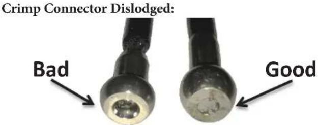 |
CHAPTER 3: CARE & MAINTENANCE
Cable Tension:
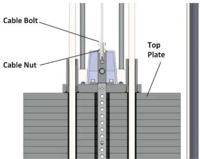
Ensure that the cables are adjusted to remove any slack using the threaded end fittings. These are normally located at the weight stack connection. Depending upon the machine, there may be multiple threaded fitting on multiple cables. You can determine if there is too much slack by performing the exercise. As you start to move a load arm or handle, the weight stack should lift immediately. If not, the cable tension needs to be adjusted.
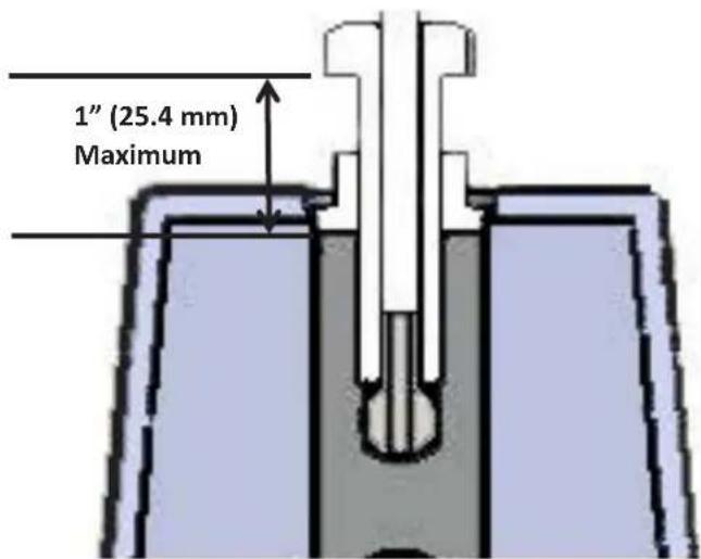
To adjust the cable tension, loosen the cable nut that is located on the cable bolt connected to the top plate. Tighten the cable bolt until the top plate is barely lifted off of the first weight plate and then re-tighten the cable nut.
CAUTION:
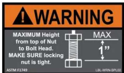
A minimum of 1/2 inch (12.7mm) of the threaded portion of the cable bolt must be threaded into the top plate.
*No more than 1 inch (25.4 mm) of the threaded portion of the cable bolt should be visible.
natural_image
Metal chain carabiner with rounded ends and a looped end (no text or symbols)Handle Fittings (if applicable):
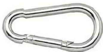
Inspect the cable fittings where any handles are attached to the end of the cable. The fittings supplied with this machine are load rated snap-links. Ensure that the snap-link opens and closes easily and is fully engaged when closed. Replace the snap-link as needed.
CHAPTER 4: CUSTOMER SERVICE
CONTACTING SERVICE:
TRUE Fitness recommends that you gather the serial number, model number, and a brief description of the reason for the request. After information has been gathered you may choose to contact your selling dealer or local service company to set an appointment. (If you are not familiar with who is in your area, you may visit our website at www.truefitness.com and use our dealer locator to obtain the contact information for the closest dealer).
You may also contact TRUE Fitness' customer support team by calling 800-883-8783 or emailing us at service@truefitness.com Monday — Friday during normal hours of operation.
TRUE FITNESS SERVICE DEPARTMENT
865 HOFF ROAD
ST. LOUIS, MO 63366
1.800.883.8783
HOURS OF OPERATION: 8:30 A.M. - 5:00 P.M. CST
E-MAIL: service@truefitness.com
CONTACTING SALES:
Interested in TRUE products? Please contact us with any sales or product inquires so that we may direct you to the appropriate sales representative to answer your questions.
E-MAIL: sales@truefitness.com
CHAPTER 4: CUSTOMER SERVICE
REPORTING FREIGHT OR PARTS DAMAGE:
Unfortunately, sometimes materials can be damaged during shipment. If materials are damaged during shipment, please follow the guidelines below to determine the appropriate process for you to follow in case of damages.
Severe Damage:
Obvious damage to external packaging / internal product. Please refuse the shipment and it will be returned to TRUE Fitness by the carrier. Contact the TRUE Fitness customer support team by calling 800.883.8783 or sales support team by calling 800.426.6570 Monday-Friday during normal hours of operation to notify us that the shipment has been refused. Once we have received the damaged shipment, a replacement shipment will be sent to you. Only refuse the damaged piece if the shipment is multiple boxes.
Slight Damage:
The box may have minimal damages and you are not sure if the actual product is damaged or not. You must sign the bill of lading as damaged when accepting the shipment. Once you have opened the box and you have determined something is indeed damaged please gather the serial number, model number, description and photos of damages. Please make sure the photos include the damaged product as well as the damaged box the product arrived in. Contact the TRUE Fitness customer support team by calling 800.883.8783 or sales support team by calling 800.426.6570 Monday-Friday during normal hours of operation.
Concealed Damage:
You may receive a shipment that looks intact and discover once the box has been opened that there are hidden damages. Please notify the carrier immediately. We will not be able to file a claim if the carrier is not notified in a timely manner. Once you have called the carrier you will need to gather the serial number, model number, description and photos of damages. Contact the TRUE Fitness customer support team by calling 800.883.8783 or sales support team by calling 800.426.6570 Monday-Friday during normal hours of operation.
CHAPTER 5: WARRANTY INFORMATION
Save Time and Register Online!
Activate Multiple Warranties at truefitness.com
All TRUE® Fitness products are distributed by TRUE and are warranted to the original registered product purchaser and the parts of the TRUE product (the "Product") listed below, under normal use and service, shall be free of manufacturing defects in workmanship and materials only for the period of time beginning from the original date of purchase set forth below:
| Frame* 10 Years | |
| Parts | |
| • Bearings (Excluding Linear Bearings), Bushings, and Weight Plates | 5 Years |
| • Guide Rods and Pulleys | 5 Years |
| • Cables, Belts, Linear Bearings, Linear Shafts, and all other components not mentioned elsewhere in this warranty | 1 Year |
| • Cosmetics, Coatings, Grips, and Upholstery | 3 Months |
| Labor | |
| • Frame | 1 Year |
| • Bearings (Excluding Linear Bearings), Bushings, Weight Plates | 1 Year |
| • Guide Rods and Pulleys | 1 Year |
| • Cables, Belts, Linear Bearings, Linear Shafts, and all other components not mentioned elsewhere in this warranty | 1 Year |
| • Cosmetics, Coatings, Grips, and Upholstery | 3 Months |
NOTE: Warranty valid for USA and Canada only.
NOTE: Failure to register this product will result in no servicing or authorization of parts to be shipped.
NOTE: Buying after-market products from a 3rd party will result in voided warranty.
NOTE: This product is intended for Commercial use. If this product will not be used in this particular setting, please contact TRUE as warranty is void.
Frame: The frame is warranted for defects in material and workmanship for a 10 years. The frame is warranted for labor and freight (for parts shipped from TRUE) for one year from date of purchase. * This limited warranty on structural frame does not include paint or coatings.
Parts: The Palladium Strength Line's mechanical parts including sealed rotating bearings, bushings, weight plates, guide rods and pulley wheels are warranted for defects in material and workmanship for five years with one year labor
warranty. Cables, belts, linear bearings, linear shafts, and all other mechanical parts not mentioned elsewhere are warranted for defects in material and workmanship for one year with one year labor warranty. This limited warranty does not cover damage or equipment failure resulting from or caused by improper assembly/installation, failure to follow instructions and warnings in owner's manual, accident, misuse, abuse, unauthorized modification, or failure to provide reasonable and necessary maintenance.
Cosmetics: The Palladium Strength Line's cosmetic parts, coatings, grips and upholstery are warranted for defects in material and workmanship for three months with labor warranty to match the parts warranty period. This limited warranty does not cover damage or equipment failure resulting from or caused by improper assembly/installation, failure to follow instructions and warnings in owner's manual, accident, misuse, abuse, unauthorized modification, or failure to provide reasonable and necessary maintenance. This limited warranty will apply to, but may not be limited to, plastic covers, shrouds, caps, badges, overlays, paint, coatings, soft step inserts, and grips.
Labor: Labor is covered for a period of one year from the date of purchase unless otherwise expressed within this limited warranty as long as a TRUE authorized service provider performs the service. Service that requires over 50 miles of travel may be subject to additional charges. Reasonable and necessary maintenance guidelines can be found in the owner's manual.
Claims Procedure: TRUE Limited Warranty service may be obtained by contacting the authorized TRUE dealer from whom the Product was purchased. If the dealer from whom the Product was purchased is no longer an authorized TRUE dealer, then TRUE Limited Warranty service may be obtained by contacting TRUE directly using the following contact information:
TRUE Fitness, Service Department
865 Hoff Road, St. Louis, MO 63366
1.800.883.8783
Hours of operation 8:30am - 5:00 pm CST
CHAPTER 5: WARRANTY INFORMATION
Save Time and Register Online!
Activate Multiple Warranties at truefitness.com
The above Limited Warranty is subject to and will be in accordance with the conditions set forth below:
-
THIS LIMITED WARRANTY GIVES YOU SPECIAL LEGAL RIGHTS AND YOU MAY ALSO HAVE OTHER RIGHTS, WHICH VARY FROM STATE TO STATE.
-
This Limited Warranty can be processed only if the Warranty Registration Form is completed online, or if the attached form is filled in, signed by the original purchaser, and mailed to TRUE within 30 days of purchaser's receipt of this Product. The serial number must be intact on the Product for this Limited Warranty to be valid.
-
This Limited Warranty applies to the product only while the Product remains in the possession of the original purchaser and is not transferable
-
This Limited Warranty becomes VALID ONLY if the Product is initially assembled/installed by a TRUE authorized dealer/ technician (if anyone other than a TRUE authorized dealer/ technician initially assembles and installs the Product, this Limited Warranty will be void unless the written authorization of TRUE is first obtained).
-
This Limited Warranty does not cover damage or equipment failure resulting from or caused by improper assembly/installation, failure to follow instructions and warnings in owner's manual, accident, misuse, abuse, unauthorized modification, or failure to provide reasonable and necessary maintenance (as referenced in thw owner's manual.)
-
This Limited Warranty applies only to the cost of repair or replacement of parts and does not include labor (beyond the above warranty period), transportation, service, return and freight charges associated therewith except as expressly specified herein.
-
This Limited Warranty shall not apply to: Service calls to correct installation of the equipment or instruction to owners on how to use the equipment; or any labor costs incurred beyond the applicable labor warranty period.
-
This Limited Warranty, which is given expressly and in lieu of all other express warranties, constitutes the only warranty made by TRUE.
-
ANY IMPLIED WARRANTY, INCLUDING WITHOUT LIMITATION THE WARRANTIES OF MERCHANTABILITY AND FITNESS FOR A PARTICULAR PURPOSE, IS LIMITED IN DURATION AND REMEDY TO THE TIME PERIOD COVERED BY THE LIMITED WARRANTY. SOME STATES DO NOT ALLOW LIMITATIONS ON HOW LONG AN IMPLIED WARRANTY LASTS, SO THE ABOVE LIMITATION MAY NOT APPLY TO YOU.
-
THE REMEDIES DESCRIBED ABOVE ARE YOUR SOLE AND EXCLUSIVE REMEDIES AND TRUE'S ENTIRE LIABILITY
FOR ANY BREACH OF THIS LIMITED WARRANTY. TRUE'S LIABILITY SHALL UNDER NO CIRCUMSTANCES EXCEED THE ACTUAL AMOUNT PAID BY YOU FOR THE PRODUCT, NOR SHALL TRUE UNDER ANY CIRC UMSTANCES BE LIABLE FOR ANY CONSEQUENTIAL, INCIDENTAL, SPECIAL, OR PUNITIVE DAMAGES OR LOSSES, WHETHER DIRECT OR INDIRECT. SOME STATES DO NOT ALLOW THE EXCLUSION OR LIMITATION OF INCIDNETIAL OR CONSEQUENTIAL DAMAGES, SO THE ABOVE LIMITATION OR EXCLUSION MAY NOT APPLY TO YOU.
NOTE TO AUTHORIZED WARRANTY LABOR PROVIDERS:
Warranty labor reimbursement or warranty parts rights may not be transferred to, reassigned to, a third party without the express written consent of TRUE. Even jobbing out warranty labor requires TRUE's written approval.
PALLADIUM STRENGTH LINE SERIAL NUMBER:
The Palladium Strength Line comes with one serial number on the base of the machine. Please write down your serial number below and keep for your records.
SERIAL NUMBER:
SAMPLE SERIAL NUMBER STICKER:
TRUE
TRUE FITNESS TECHNOLOGY, INC
865 HOFF RD, ST LOUIS MISSOURI 63366 USA
MODEL NO: SPL0100
SERIAL NO: 19-SPL010001A
Keep this page for your records
Page # 35 of 36
CHAPTER 5: WARRANTY INFORMATION
Thank you for purchasing a TRUE product. To validate the TRUE product warranty the fast and easy way, please go on-line now to truefitness.com/support and register your product. The information you provide will never be distributed to any other individuals or agencies for any purpose. If you prefer to mail your warranty card, have the owner of the product complete the information below and return it to TRUE Fitness within 30 days from the date of equipment installation.
To mail your warranty information, please fill in the information below and mail to: Service Dept., TRUE Fitness, 865 Hoff Road, St. Louis, MO 63366 (or save postage and register online at truefitness.com)
Commercial Warranty Registration
PLEASE PROVIDE YOUR SERIAL NUMBER BELOW. REQUIRED FOR WARRANTY REGISTRATION:
SERIAL NUMBER:
Model Type ____
Date of Purchase
Your Company Name
Contact First Name
Contact Last Name
Address
City State ZIP
Email Address Website
Phone Fax
- Where did you first learn about TRUE?
a. Dealer b. Website
____ c. Advertisement ____ d. Referral
____ e. Current Customer ____ f. Other ____
- Why did you purchase a TRUE product?
a. Design/Appearance b. Dealer Suggestion
____ c. Price/Value ____ d. Quality Construction
e. Performance f. TRUE Reputation
g. Other
- Please indicate your type of facility:
a. Apartment/Condo b. Corporate Fitness Center
____ c. Municipality ____ d. Health Club/Gym/Spa
____ e. Hotel/Resort ____ f. Military Base
____ g. Student Rec Center ____ h. Other
- What other types of equipment does your company ly own?
a. Treadmill Brand
b. Bike Brand
c. Elliptical Brand
d. Free Weights/Gym Brand
- How many people use your facility on a daily basis?
a. <25 b. 25-75
____ c. 76-150 ____ d. 150+
- Do you plan to purchase more fitness equipment in the next 6-12 months?
____ Yes ____ No
- If you answered "yes" to question 6, what type do you plan to purchase?
a. Treadmill b. Elliptical
____ c. Stationary Bike ____ d. Free Weights
____ e. Gym ____ f. Other ____
- Would you recommend TRUE to other club owners?
____ Yes ____ No
- You are a valued TRUE customer and your suggestions allow us to continually improve your experience. Is there anything else you would like us to know? Please explain:
- Palladium Strength Line
- IMPORTANT:
- IMPORTANTE:
- A MESSAGE TO OUR CUSTOMERS
- Table of Contents
- CHAPTER 1: SAFETY INSTRUCTIONS ....5
- CHAPTER 2: ASSEMBLY GUIDE ....10
- CHAPTER 3: CARE & MAINTENANCE....28
- CHAPTER 4: CUSTOMER SERVICE....32
- CHAPTER 5: WARRANTY INFORMATION ....34
- CHAPTER 1: SAFETY INSTRUCTIONS
- FACILITY AND USER SAFETY PRECAUTIONS
- INSTALLATION SAFETY PRECAUTIONS
- MAINTENANCE SAFETY PRECAUTIONS
- BOLT LENGTH MEASURING GUIDE
- IMPORTANT
- COMPLIANCES:
- CHAPTER 2: ASSEMBLY GUIDE
- WORKOUT PLACARDS:
- ASSEMBLY STEPS:
- Step 1 (Top Cap Tray):
- Step 3 (Guide Rods and Weight Stack Cable):
- Step 4A (Weight Stack Configuration):
- Step 5 (Front Acrylic Shrouds):
- Step 7 (Front Acrylic Shrouds):
- Step 8 (Rear Acrylic Shrouds):
- Step 9 (Rear Acrylic Shrouds):
- Step 12 (Rear Metal Shroud):
- CHAPTER 3: CARE & MAINTENANCE
- CARE & MAINTENANCE:
- DAILY INSPECTION&MAINT'EMANCE:
- WEEKLY INSPECTION&MAINTENANCE:
- OTHER SCHEDULED PREVENTIVE MAINTENANCE:
- Monthly:
- Every 6 months:
- CLEANING THE EQUIPMENT:
- Daily Cleaning:
- CAUTION:
- Heavy Duty Cleaning:
- CABLE INSPECTION & MAINTENANCE:
- Cable Wear:
- Cable Tension:
- Handle Fittings (if applicable):
- CHAPTER 4: CUSTOMER SERVICE
- CONTACTING SERVICE:
- CONTACTING SALES:
- REPORTING FREIGHT OR PARTS DAMAGE:
- Severe Damage:
- Slight Damage:
- Concealed Damage:
- CHAPTER 5: WARRANTY INFORMATION
- Save Time and Register Online!
- Activate Multiple Warranties at truefitness.com
- Commercial Warranty Registration
- PLEASE PROVIDE YOUR SERIAL NUMBER BELOW. REQUIRED FOR WARRANTY REGISTRATION:
- SERIAL NUMBER:
Brand : True
Model : Palladium
Category : Weight bench