
RE140eP - Instant water heater and boiler Rinnai - Free user manual and instructions
Find the device manual for free RE140eP Rinnai in PDF.


| Product Type | Tankless Water Heater (Outdoor) |
| Brand | Rinnai |
| Model | RE140eP |
| Weight | 38.3 lbs (17.4 kg) |
| Power Supply | 120 V AC, 60 Hz, 4 Amps max, 10 Amp fuse |
| Power Consumption (Normal) | 52 W |
| Maximum Gas Consumption | 140,000 Btu/h |
| Minimum Gas Consumption | 10,400 Btu/h |
| Flow Rate (Min-Max) | 0.26-5.3 GPM (1.0-20 L/min) |
| Temperature Range | 120°F – 140°F (49°C – 60°C) |
| Gas Type | Natural Gas or Propane (LPG) |
| Gas Supply Pressure (Natural Gas) | 4.0 – 10.5 in. wc |
| Gas Supply Pressure (Propane) | 8.0 – 13.0 in. wc |
| Water Supply Pressure | 20 – 150 PSI (recommended 30-80 PSI) |
| Sound Level | 54 dB |
| Type of Appliance | High-Efficiency (Non-condensing), Tankless, Continuous Flow Gas Hot Water System |
| Ignition System | Direct Electronic Ignition |
| Mounting | Wall mount (brackets included) |
| Venting | Direct vent (outdoor model, no venting required) |
| Freeze Protection | Integrated electric freeze protection (down to -4°F/-20°C with power) |
| Control Type | Digital temperature controller with LCD display |
| Warranty (Heat Exchanger) | 15 years residential / 8 years commercial |
| Warranty (Parts) | 5 years |
| Warranty (Labor) | 1 year |
Frequently Asked Questions - RE140eP Rinnai
User questions about RE140eP Rinnai
0 question about this device. Answer the ones you know or ask your own.
Ask a new question about this device
Download the instructions for your Instant water heater and boiler in PDF format for free! Find your manual RE140eP - Rinnai and take your electronic device back in hand. On this page are published all the documents necessary for the use of your device. RE140eP by Rinnai.
USER MANUAL RE140eP Rinnai
RE199i (REU-VE2737FFD-US)
RE180i (REU-VE2432FFD-US)
RE160i (REU-VE2125FFD-US)
RE140i(REU-VE1720FFD-US)
OUTDOOR MODELS:
RE199e (REU-VE2737WD-US)
RE180e (REU-VE2432WD-US)
RE160e (REU-VE2125WD-US)
RE140e(REU-VE1720WD-US)
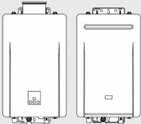
natural_image
Technical line drawings of two identical electrical enclosure units with mounting brackets and control panel (no text or symbols)



ANSIZ21.10.3 CSA 4.3
Tankless Water Heater
Installation and Operation Manual
Rinnai®

WARNING
If the information in these instructions is not followed exactly, a fire or explosion may result causing property damage, personal injury, or death.
- Do not store or use gasoline or other flammable vapors and liquids in the vicinity of this or any other appliance.
• WHAT TO DO IF YOU SMELL GAS - Do not try to light any appliance.
- Do not touch any electrical switch; do not use any phone in your building.
- Immediately call your gas supplier from a neighbor's phone. Follow the gas supplier's instructions.
– If you cannot reach your gas supplier, call the fire department. - Installation and service must be performed by a trained and qualified professional, service agency or the gas supplier.

Full-length Spanish version available online at rinnai.us
Copyright 2021 Rinnai America Corporation. Rinnai® is a registered trademark of Rinnai Corporation used under license by Rinnai America Corporation. Rinnai America Corporation continually updates materials, and as such, content is subject to change without notice.
Contents
- Welcome .... 5
- Safety 6
2.1 Safety Symbols 6
2.2 Safety Precautions....6
- About the Water Heater....8
3.1 Front and Bottom View 8
3.2 Main Components....9
3.3 Specifications....10
3.4 Dimensions....11
3.5 Accessories 13
- Install the Water Heater....15
4.1 Installation Guidelines .... 15
4.2 What You Will Need 16
4.3 Choose an Installation Location....17
4.4 Mount the Water Heater to the Wall....22
4.5 Vent the Water Heater 24
4.6 Connect Water Supply 32
4.7 Install Pressure Relief Valve 33
4.8 Connect the Gas Supply 34
4.9 Connect the Power Supply 37
4.10 Configure Parameter Settings 38
4.11 Recirculation 40
4.12 Post-Water Heater Installation Checklist 41
- Operation....43
5.1 Safety Precautions....43
5.2 Operating Instructions....44
5.3 Control Panel....45
5.4 Setting the Temperature 46
5.5 Performance Data....47
5.6 Diagnostic Codes....49
6. Maintenance 53
6.1 Maintenance 53
6.2 Flushing the Heat Exchanger 56
6.3 Draining the Water Heater 57
7. Appendices 58
7.1 Massachusetts State Gas Regulations....58
7.2 Wiring Diagram....60
7.3 Ladder Diagram....61
7.4 Pressure Drop and Water Flow Curves 62
7.5 Guidelines for Additional Temperature Controllers 63
8. Warranty 64
1. Welcome
Thank you for purchasing a Rinnai Tankless Water Heater. Before installing and operating this water heater, be sure to read these instructions completely and carefully to familiarize yourself with the water heater's features and functionality.
To The Installer
- It is recommended that a trained and qualified professional who has attended a Rinnai training class complete the installation. The warranty may be voided due to any improper installation.
-
A trained and qualified professional should have skills such as:
-
Gas sizing
- Connecting gas lines, water lines, valves, and electricity
– Knowledge of applicable national, state, and local codes -
Installing venting through a wall or roof
– Training in installation of tankless water heaters. Training on Rinnai Tankless Water Heaters is accessible at www.rinnai-lms.com -
Read all instructions in this manual before installing the water heater. The water heater must be installed according to the exact instructions in this manual.
- Proper installation is the responsibility of the trained and qualified professional.
- When installation is complete, leave this manual with the water heater (for indoor units) or give the manual directly to the consumer.
To The Consumer
- You must read the entire manual to properly operate the water heater.
- Refer to section "6 Maintenance" to stay up to date on regular maintenance for your water heater.
- Keep this manual for future reference.
- As when using any appliance generating heat, there are certain safety precautions you should follow. See section "2 Safety" for detailed safety precautions.
- Be sure your water heater is installed by a trained and qualified professional.
- If installing in the state of Massachusetts, you must read section "7.1 Massachusetts State Gas Regulations" in this manual.
Acronyms and Abbreviations
Table 1 provides a list of common acronyms and abbreviations used in this manual:
Table 1
| ANSI | American National Standards Institute |
| BTU | British Thermal Unit |
| GPM | Gallons per minute |
| LPG | Liquefied Petroleum Gas |
| NG | Natural Gas |
| PRV | Pressure Relief Valve |
| PSI | Pounds per square inch |
| wc | Inches of water column |
| NPT | National Pipe Thread |
| MNPT | Male National Pipe Thread Taper |
| V AC | Volts, alternating current |
2.2. SafetySafety

WARNING
- If the information in these instructions is not followed exactly, a fire or explosion may result causing property damage, personal injury, or death.
- Do not store or use gasoline or other flammable vapors and liquids in the vicinity of this or any other appliance.
• WHAT TO DO IF YOU SMELL GAS:
- Do not try to light any appliance.
- Do not touch any electrical switch; do not use any phone in your building.
- Immediately call your gas supplier from a neighbor's phone. Follow the gas supplier's instructions.
- If you cannot reach your gas supplier, call the fire department.
• Installation and service must be performed by a trained and qualified professional, service agency or the gas supplier.
- The warning signs in this manual are here to prevent injury to you and others. Please follow them explicitly.
21 Safety Symbols

Safety alert symbol alerts you to potential hazards that can kill or hurt you and others.
DANGER
Indicates an imminently hazardous situation which, if not avoided, will result in personal injury or death.
WARNING
Indicates a potentially hazardous situation which, if not avoided, will result in personal injury or death.
CAUTION
Indicates a potentially hazardous situation which, if not avoided, could result in minor or moderate injury. It may also be used to alert against unsafe practices.
2.2 Safety Precautions
The following precautions apply to the trained and qualified professional and consumer. Read and follow all instructions in this section.
- Before operating, smell all around the appliance area for gas. Be sure to smell next to the floor because some gas is heavier than air and will settle on the floor.
- Keep the area around the appliance clear and free from combustible materials, gasoline, and other flammable vapors and liquids.
-
Combustible construction refers to adjacent walls and ceiling and should not be confused with combustible or flammable products and materials. Combustible and/or flammable products and materials should never be stored in the vicinity of this or any gas appliance.
• Always check the water temperature before entering a shower or bath.
• To protect yourself from harm, before performing maintenance: -
Turn off the electrical power supply by unplugging the power cord or by turning off the electricity at the circuit breaker. (The temperature controller does not control the electrical power.)
- Turn off the gas at the manual gas control valve, usually located immediately below the water heater.
- Turn off the incoming water supply. This can be done at the isolation valve immediately below the water heater or by turning off the water supply to the building.
- Use only your hand to turn the manual gas control valve. Never use tools. If
the manual gas control valve will not turn by hand, do not try to repair it; call a trained and qualified professional. Force or attempted repair may result in a fire or explosion.
- DO NOT use this appliance if any part has been under water. Immediately call a trained and qualified professional to inspect the appliance and to replace any part of the control system and any manual gas control valve which has been under water.
- DO NOT use substitute materials. Use only parts certified for the appliance.
- Should overheating occur or the gas supply fail to shut off, turn off the manual gas control valve to the appliance.
- DO NOT adjust the parameter settings unless specifically instructed to do so. Only trained and qualified professionals are permitted to adjust parameter settings.
- DO NOT use an extension cord or adapter plug with this appliance.
- Any alteration to the appliance or its controls can be dangerous and will void the warranty.
- Proper venting is required for the safe operation of this appliance.
- Flammable liquids such as cleaning solvents, aerosols, paint thinners, adhesives, gasoline and propane must be handled and stored with extreme care. These flammable liquids emit flammable vapors and when exposed to an ignition source can result in a fire hazard or explosion. Flammable liquids should not be used or stored in the vicinity of this or any other gas appliance.
- DO NOT operate the water heater without the front panel installed. The front panel should only be removed when servicing/maintaining or replacing internal components.
- BURN HAZARD. Hot exhaust and vent may cause serious burns. Keep away from the water heater. Keep small children and animals away from the water heater.
- Hot water outlet pipes leaving the water heater can be hot to touch.
• Install the vent system per local and national codes.
• DO NOT install this water heater above 10,200 ft (3,109 m).
- DO NOT obstruct combustion air to the appliance. Combustion air shall not come from occupied spaces.
- Failure to properly vent this appliance can result in death, personal injury and/or property damage.
- Rinnai recommends that every home have a carbon monoxide (CO) alarm in the hallway near bedrooms in each sleeping area. Check batteries monthly and replace them annually.
- DO NOT use this appliance in an application such as a pool or spa heater that uses chemically treated water. (This appliance is suitable for filling large or whirlpool spa tubs with potable water.)
3. About the Water Heater
Topics in this section
- Front and Bottom View
- Main Components
- Specifications
- Dimensions
- Accessories
3.1 Front and Bottom View
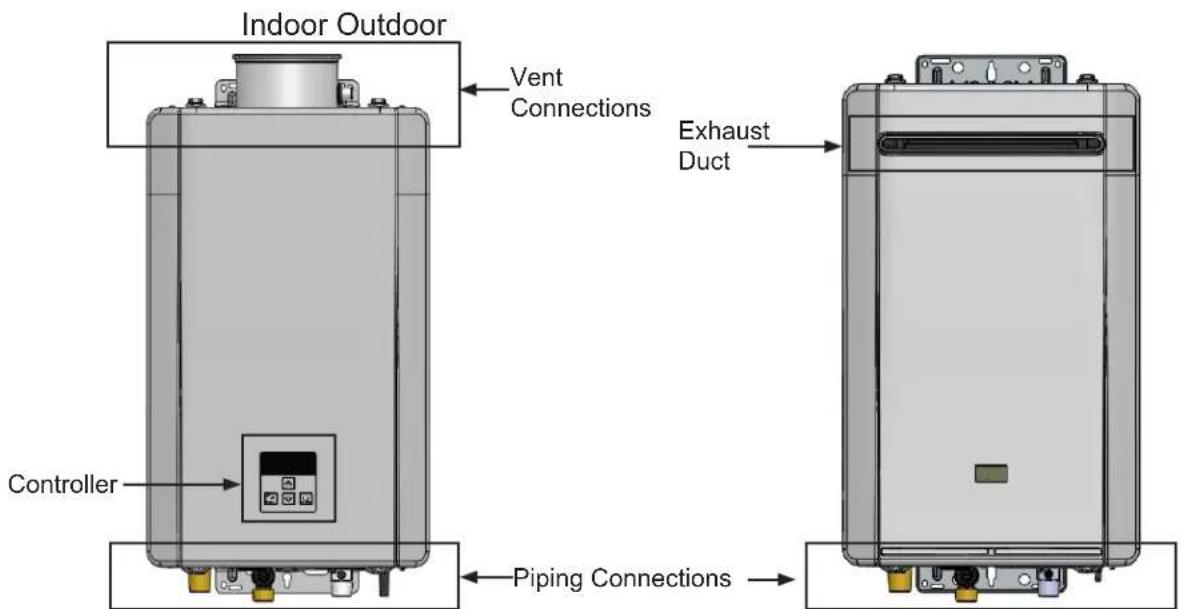
Figure 1: Front view
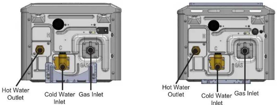
Figure 2: Bottom view
3.2 Main Components
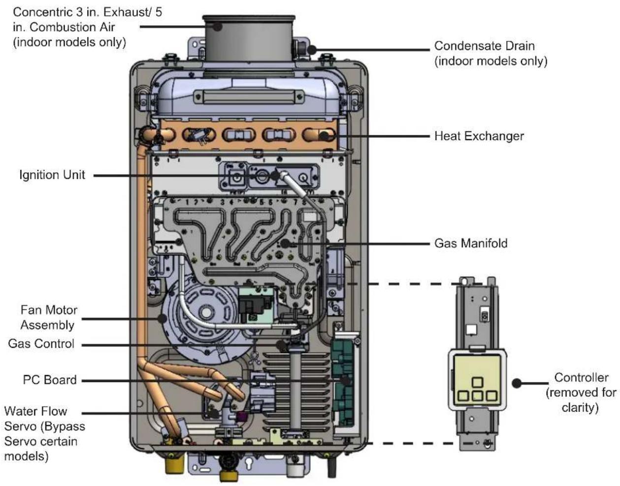
Figure 3: Main Components
3.3 Specifications
Table 2: Specifications
| Indoor Units Outdoor Units | |||||||||
| RE199I RE1 | 80I RE160I RE1 | 40I RE199e RE1 | 30e RE160e RE1 | 40e | |||||
| Minimum Gas Consumption Btu/h | 10,400 | ||||||||
| Maximum Gas Consumption Btu/h | 199,000 180 | 000 160,000 140 | 000 199,000 180 | 000 160,000 140 | 000 | ||||
| Flow Rate ^1 (Min-Max) | 0.13-9.8 GPM(0.5-37 L/min) | 0.13-8.5 GPM(0.5-32 L/min) | 0.26-6.6 GPM(1.0-25 L/min) | 0.26-5.3 GPM(1.0-20 L/min) | 0.13-9.8 GPM(0.5-37 L/min) | 0.13-8.5 GPM(0.5-32 L/min) | 0.26-6.6 GPM(1.0-25 L/min) | 0.26-5.3 GPM(1.0-20 L/min) | |
| Weight | 42.1 lbs (19.1 kg) | 38.5 lbs (17.5 kg) | 42.1 lbs (19.1 kg) | 38.3 lbs (17.4 kg) | |||||
| Sound Level | 54 dB | 54 dB | |||||||
| Electrical Data | Normal | 96 | 87 | 91 | 71 | 74 | 61 | 60 | 52 |
| Standby | 1 | ||||||||
| Freeze Protection | 86 | 100 | |||||||
| Max Current | 4 Amps | ||||||||
| Fuse | 10 Amps | ||||||||
| Temperature Setting | 98°F-140°F (37°C-60°C) | 120°F-140°F (49°C-60°C) | 98°F-140°F (37°C-60°C) | 120°F-140°F (49°C-60°C) | |||||
| Bypass Flow Control | Bypass Servo Control | Fixed Bypass | Bypass Servo Control | Fixed Bypass | |||||
| Gas Supply Pressure ^2 | Natural Gas | 4.0 in. wc - 10.5 in. wc | |||||||
| Propane | 8.0 in. wc - 13.0 in. wc | ||||||||
| Type of Appliance | High-Efficiency (Non-condensing), Tankless, Temperature Controller, Continuous Flow Gas Hot Water System | ||||||||
| Ignition System | Direct Electronic Ignition | ||||||||
| Electric Connections | Appliance: AC 120 Volts, 60Hz | ||||||||
| Water Supply Pressure | Minimum water pressure: 20 PSI (Recommended 30-80 PSI for maximum performance)Maximum water pressure: 150 PSI | ||||||||
| Remote Control Cable | Non-Polarized Two Core Cable (Minimum 22 AWG) | ||||||||
| ENERGY STAR® Qualified | No | ||||||||
| Complies with South Coast Air Quality Management District 14 ng/J or 20 ppm NOx emission levels | Yes | ||||||||
^1 Minimum flow may vary slightly depending on the temperature setting and the inlet water temperature. Minimum activation flow is 0.4 GPM (1.5 L/min) (0.26 GPM (1.0 L/min) for RE199 and RE180).
^2 The maximum gas supply pressure must not exceed the value specified by the manufacturer.
Rinnai products are continually being updated and improved; therefore, specifications are subject to change without prior notice.
3.4 Dimensions
Measurements: in. (mm)
Indoor Models
(RE199i, RE180i, RE160i, and RE140i)
Front View Side View
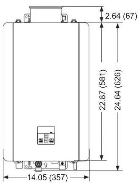
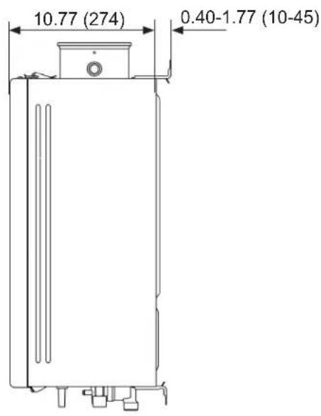
Figure 4: Indoor Dimensions
Outdoor Models
(RE199e, RE180e, RE160e, and RE140e)
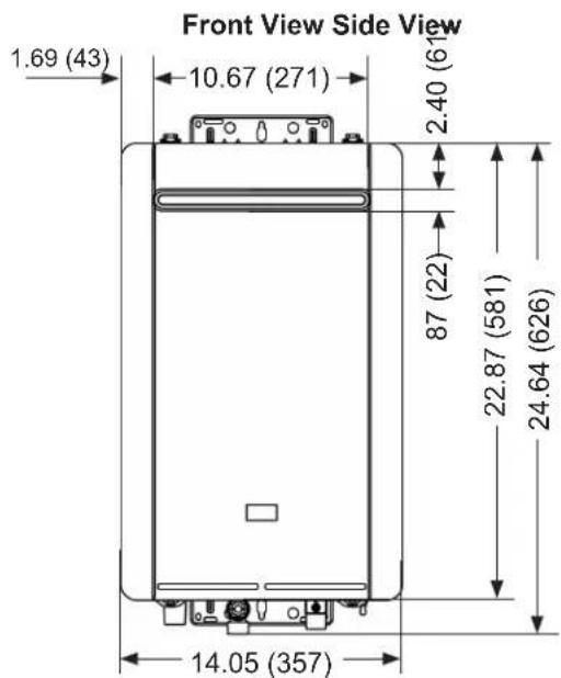
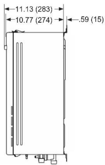
Figure 5: Outdoor Dimensions
3.4.1 Supply Connections
Measurements: in. (mm)
Indoor Models
(RE199i, RE180i, RE160i, and RE140i)
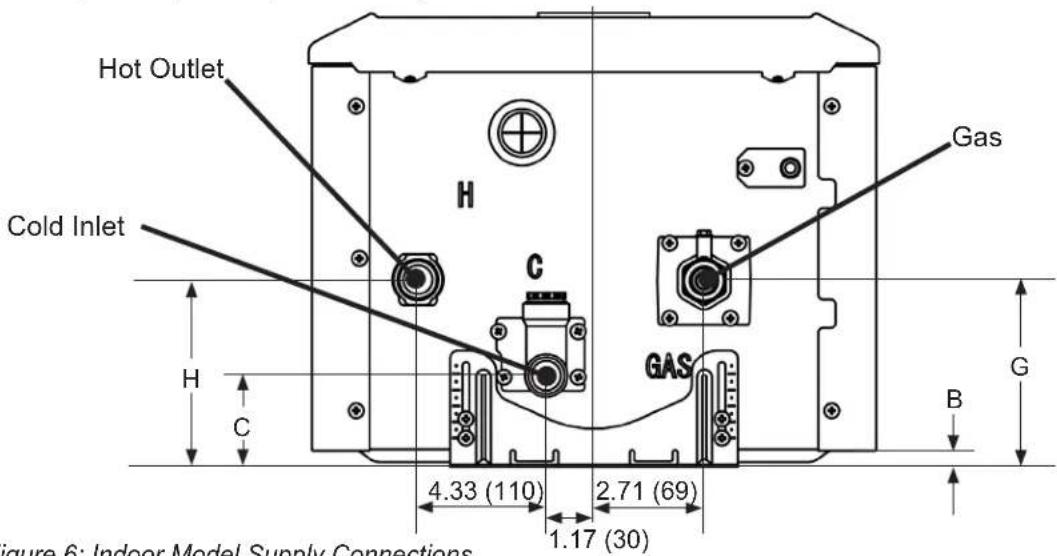
Figure 6: Indoor Model Supply Connections
Outdoor Models
(RE199e, RE180e, RE160e, and RE140e)
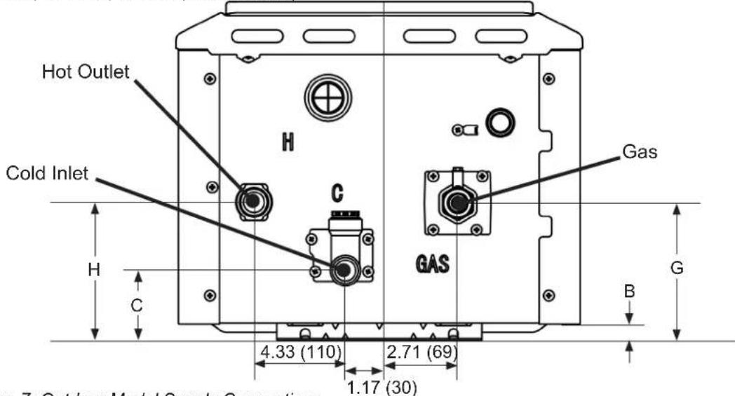
Figure 7: Outdoor Model Supply Connections
Table 3: Supply Connections
| Indoor (wall bracket retracted) | Indoor (wall bracket extended) | Outdoor | |||
| G | Gas 4.57 (116) | 5.79 (147) 4.74 (121) | 3/4 MNPT | ||
| C | Cold Inlet 2.24 | (57) 3.46 (88) 2.41 | (61) 3/4 MNPT | ||
| H | Hot Outlet | 4.6 (117) | 5.82 (148) | 4.76 (120) | 3/4 MNPT |
| B | Bracket | .40 (10) | 1.6 (41) | 0.59 (15) | N/A |
3.5 Accessories
Numerous optional accessories are available for purchase for your Rinnai Tankless Water Heater. Listed below are some commonly purchased accessories. For a complete list of accessories, visit www.rinnai.us.
For questions, or to purchase an accessory, contact your local Rinnai dealer/distributor or Rinnai Customer Care at 1-800-621-9419.
Table 4: Accessories
| Product Product Description Image | ||
| ScaleCutterPart #: 103000038 | Filters and reduces the amount of scale entering the water heater allowing for greater water heater longevity. | 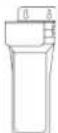 |
| ScaleCutter Refill CartridgePart #: 103000039 | Refill cartridge for the ScaleCutter filter assembly. |  |
| Drain Down KitPart #: 104000059 | Provides freeze protection by immediately draining the water heater upon loss of power. | 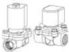 |
| Additional ControllerPart #: MC-601-BKMC-601-WMC-195T-USMCC-601 | Additional controllers are available for user convenience. | 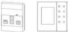 |
| Recess BoxPart #: RGB-CTWH-5 | Allows an outdoor water heater to be recessed into a wall. |  |
| Pipe CoverPart #: PCD09-SHS | Encloses the piping below the water heater for aesthetic purposes. | 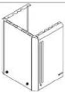 |
| control•rTM Wi-Fi Module (And Accessories)Part #: RWM101 | Controls On-Demand recirculation, remotely adjust temperatures, and communicates with the Pro Portal. The control•rTM Wi-Fi Module and MC-195T-US controller are not compatible accessories and must not be installed together. | 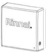 |
| External Pump CablePart #: 105000250 | Provides electrical connections for external recirculation pump control. | 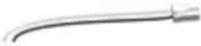 |
| EZConnectTM CablePart #: REU-EZC-2 | Electronically connects two water heaters and allows them to function as one hot water source. |  |
| Product Product Description Image | ||
| DPS/MIS Switch Part #: REU-OPU3 | The Domestic Priority Switch (DPS) function provides domestic hot water priority for combined tankless water heater and air handler use.The Maintenance Indication Switch (MIS) function enables tankless water heater monitoring via programs such as Building Management System (BMS). | 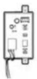 |
| Isolation Valve Part #: MIVK-T-LW | Isolation valves provide the ability to isolate the water heater from the structure's plumbing system and allow quick and easy access to flush the heat exchanger. | 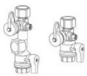 |
| Dedicated Return Valve Part #: 107000450 | Valve kit including tee, drain valve, check valve and isolation valve to simplify set-up of a dedicated recirculation line. | 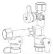 |
| Wall Mounting Bracket Part #: 109000628 | Optional accessory for mounting the water heater to the wall. | 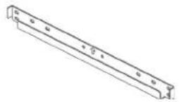 |
| Cold Weather Kit Part #: REColdKit | Electric heater, bottom pipe cover, and insulation panels for use with Pipe Cover (Part #: PCD09-SHS) | 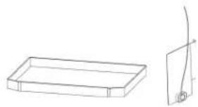 |
| Leak Detection Kit Part #: RELeakKit | Pipe cover drain pan and float switch for use with Pipe Cover (Part #: PCD09-SHS) | 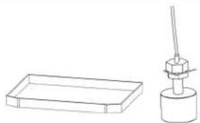 |
| Battery Backup Part #: R-UPS350A | Tankless battery backup system, 500VA/350W uninterrupted power supply (UPS), Hot water usage of 1 hour per day with sufficient power for 5-7 days. | 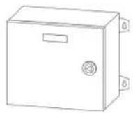 |
| Recirculation Pump Part #: GTK03U | A pump system can be incorporated with Rinnai Circ-Logic recirculation technology in a dedicated recirculation system. | 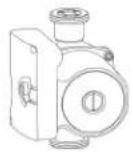 |
4. Install the Water Heater
Topics in this section
• Installation Guidelines
• What you will need
- Choose Installation Location
- Mount Water Heater to the Wall
- Vent Water Heater
- Connect Water Supply
• Install Pressure Relief Valve
- Connect Gas Supply
- Connect Power Supply
- Configure Parameter Settings
- Recirculation
• Post-Water Heater Installation Checklist
THIS SECTION IS INTENDED FOR THE INSTALLER
Installer qualifications: A trained and qualified professional must install the appliance, inspect it, and leak test the water heater before use. The warranty may be voided due to any improper installation. The trained and qualified professional should have skills such as: Gas sizing; Connecting gas lines, water lines, valves, and electricity; Knowledge of applicable national, state, and local codes; Installing venting through a wall or roof; and training in installation of tankless water heaters. Training for Rinnai Tankless Water Heaters is accessible online at www.trainingevents.rinnai.us.
4.1 Installation Guidelines
When installing the water heater, follow these guidelines:
- This water heater is certified for installation in residential applications and manufactured (mobile) homes.
- The installation must conform with local codes or, in the absence of local codes, with the National Fuel Gas Code, ANSI
Z223.1/NFPA 54, or the Natural Gas and Propane Installation Code, CSA B149.1. If installed in a manufactured home, the installation must conform with the Manufactured Home Construction and Safety Standard, Title 24 CFR, Part 3280 and/or CAN/SCA Z240 MH Series, Mobile Homes.
- The appliance, when installed, must be electrically grounded in accordance with local codes or, in the absence of local codes, with the National Electrical Code, ANSI/NFPA 70, or the Canadian Electrical Code, CSA C22.1.
- The appliance and its manual gas shutoff (control) valve must be disconnected from the gas supply piping system during any pressure testing of that system at test pressures in excess of 1/2 psi (3.5 kPa) (13.84 in wc).
- The appliance must be isolated from the gas supply piping system by closing its individual manual gas shutoff (control) valve during any pressure testing of the gas supply piping system at test pressures equal to or less than 1/2 psi (3.5 kPa) (13.84 in. wc).
- You must follow the installation instructions and those in section "4.5 Vent the Water Heater" for adequate combustion air and exhaust.
- If a water heater is installed in a closed water supply system, such as one having a backflow preventer in the cold water supply line, means shall be provided to control thermal expansion. Contact the water supplier or local plumbing inspector on how to control thermal expansion.
- Should overheating occur or the gas supply fail to shut off, turn off the manual gas shutoff (control) valve to the appliance.
- Combustion air must be free of chemicals, such as chlorine or bleach, that produce fumes. These fumes can damage components and reduce the life of your appliance.
DO NOT
- DO NOT install the following internal (indoor) water heaters outdoor: RE199i, RE180i, RE160i or RE140i.
- DO NOT install the following external (outdoor) water heaters indoor: RE199e, RE180e, RE160e or RE140e.
- DO NOT install the water heater in an area where water leakage of the unit or connections will result in damage to the area adjacent to the appliance or to lower floors of the structure. When such locations cannot be avoided, it is recommended that a suitable drain pan, adequately drained, be installed under the water heater. The pan must not restrict combustion air flow.
- DO NOT obstruct the flow of combustion and ventilation air. Combustion air shall not be supplied from occupied spaces.
- DO NOT use this appliance in an application such as a pool or spa heater that uses chemically treated water. (This appliance is suitable for filling large or whirlpool spa tubs with potable water.)
• DO NOT use substitute parts that are not authorized for this appliance. - DO NOT run the unit with the front cover removed during normal operation.
4.2 What You Will Need
4.2.1 Items Included
Unpack the Rinnai Tankless Water Heater package and verify the following contents are included. If any items are damaged or missing, contact your local dealer/distributor or call Rinnai Customer Care at 1-800-621-9419.
• Rinnai Tankless Water Heater
• Rinnai Tankless Water Heater Installation and Operation Manual
• Self-Tapping Screw (Indoor models only)
4.2.2 Items Needed (Field-Supplied)
• Manual Gas Control Valve
• Pressure Relief Valve
- Isolation Valves
- Pipe wrenches (x2)
- Adjustable pliers
• Phillips Head screwdriver
- Wire Cutters
- Gloves
- Safety glasses
- Level
- Soap or gas leak detector solution
- Approved venting
- Teflon tape (recommended) or pipe compound
- Pipe insulation
• Hammer drill with concrete bits
- Saw
• Threading machine with heads and oiler
- Core drill with diamond head
- Torch set
• Copper tubing cutter
- Steel pipe cutter
- Heat tape
- Electrical wire
• Concrete wall anchors
- Optional pipe cover
- Wire nuts
• Single gang electrical box
• Unions and drain valves
• 2 conductor 22 AWG wire for controller
4.3 Choose an Installation Location
When selecting an installation location, you must ensure that all water heater and venting clearances will be met and that the vent length will be within required limits. Consider the installation environment, water quality, and the need for freeze protection. Requirements for the gas line, water lines, and electrical connection can be found in their respective installation sections in this manual.
4.3.1 Water Quality Guidelines
This section provides information on the importance of water quality to the Rinnai Tankless Water Heater. The information is intended to serve as a general guide only and is not a complete list of water quality guidelines.
Consideration of care for your water heater should include evaluation of water quality. The water must be potable, free of corrosive chemicals, sand, dirt, or other contaminants. It is up to the trained and qualified professional to ensure the water does not contain corrosive chemicals or elements that can affect or damage the Rinnai Tankless Water Heater. Water that contains chemicals exceeding the levels listed in Table 6 can damage the Rinnai Tankless Water Heater. Replacement of components due to water quality damage is not covered by the warranty.
If you install this water heater in an area that is known to have hard water or that causes scale build-up, the water must be treated and may require a more frequent flushing schedule. When scale build-up in the heat exchanger begins to affect the performance of the water heater, a diagnostic code "LC" will display on the controller. Flush the heat exchanger to prevent damage to it. This water heater also includes a service indicator (Service Soon, 55). When selected in the parameter settings, an 55 code will display on the controller indicating that it is time to flush and service the water heater. Scale build-up is caused by hard water and can be accelerated if the water heater is set at a high temperature.
Rinnai offers Southeastern Filtration's "ScaleCutter Water Conditioning System" that offers superior lime scale prevention and corrosion control by feeding a blend of control compounds into the cold water supply.
Table 5
| Part Number | Description |
| 103000038 | Southeastern FiltrationScaleCutter System 3/4 in. Feed |
| 103000039 | ScaleCutter Refill |
Table 6: Water Quality Guidelines
| Contaminant Maximum Level | |
| Total Hardness Up to 200 mg/L | |
| Aluminum * Up to 0.2 mg/L | |
| Chlorides * Up to 250 mg/L | |
| Copper * Up to 1.0 mg/L | |
| Dissolved Carbon Dioxide (CO2) | Up to 15.0 mg/L |
| Iron * Up to 0.3 mg/L | |
| Manganese * | Up to 0.05 mg/L |
| pH * | 6.5 to 8.5 |
| TDS (Total Dissolved Solids) * | Up to 500 mg/L |
| Zinc * | Up to 5 mg/L |
*Source: 40 CFR Part 143 National Secondary Drinking Water Regulation
4.3.2 Environment
Air surrounding the water heater, venting, and vent termination(s) is used for combustion and must be free of any compounds that cause corrosion of internal components.
These include corrosive compounds that are found in aerosol sprays, detergents, bleaches, cleaning solvents, oil-based paints/varnishes, and refrigerants. The air in beauty shops, dry cleaning stores, photo processing labs, and storage areas for pool supplies often contains these compounds. Therefore, it is recommended that external (outdoor) models be used for these locations where possible. The water heater, venting, and vent termination(s) should not be installed in any areas where the air may contain these corrosive compounds.
In coastal regions, the water heater installation should be sheltered to minimize exposure to corrosive sea breeze.
4.3.3 Indoor Water Heaters
- DO NOT install the water heater in areas where combustion air might be contaminated with chemicals.
• Install the water heater as far away as possible from any air inlet vents. Corrosive fumes, sometimes found in hair/ nail salons, spas, or other industries exposed to toxic fumes, may be released through these vents when not in operation. Chemicals that are corrosive in nature should not be stored or used near the water heater or vent termination. This requirement applies to internal (indoor) and external (outdoor) water heaters. - Where possible, install internal (indoor) water heaters in a sealed closet so that it is protected from the potential of contaminated indoor air.
4.3.4 Outdoor Water Heaters and Vent Terminations
• Install the water heater as far away as possible from exhaust vent hoods and dryer vents.
- Damage and repair due to corrosive compounds in the air are not covered by warranty.
• Install the water heater as far away as possible from any air inlet vents. Corrosive fumes, sometimes found in hair/ nail salons, spas, or other industries exposed to toxic fumes, may be released through these vents when not in operation. Chemicals that are corrosive in nature should not be stored or used near the water heater or vent termination. This requirement applies to internal (indoor) and external (outdoor) water heaters.
4.3.5 Freeze Protection
The water heater and its water lines must be protected to prevent freezing. Damage due to freezing is not covered by the warranty.
When connected to a 120-volt power supply and gas is on, the water heater will not freeze when the outside air temperature is as cold as -22^ (-30°C) for internal (indoor) models or -4^ (-20°C) for external (outdoor) models, when protected from direct wind exposure. Because of the "wind-chill" effect, any wind or circulation of air on the water heater will reduce its ability to protect itself from freezing.
In the event of a power failure and/or gas interruption at temperatures below freezing, the water heater should manually be drained of all water to prevent freezing damage. In addition, drain the water line and pressure relief valve.
Loss of freeze protection may result in water damage from a burst heat exchanger or water lines that freeze and break.
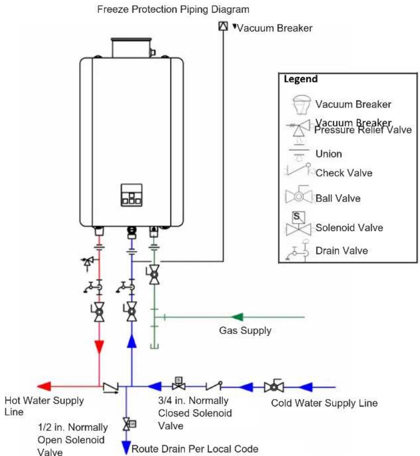
The water heater may be drained manually. However, it is highly recommended to install the optional Drain Down Kit accessory that will enable the water heater to immediately drain upon loss of power (the pressure relief valve is not affected by the Drain Down Kit and must be manually drained).
The freeze protection features will not prevent the external piping and valves from freezing. The hot and cold water pipes should be insulated. To provide additional freeze protection, the pipe cover enclosure can be filled with insulation materials.
flowchart
graph TD
    A["Freeze Protection Piping Diagram"] --> B["Vacuum Breaker"]
    B --> C["Gas Supply"]
    C --> D["Hot Water Supply Line"]
    C --> E["Cold Water Supply Line"]
    D --> F["1/2 in. Normally Open Solenoid Valve"]
    E --> G["3/4 in. Normally Closed Solenoid Valve"]
    F --> H["Route Drain Per Local Code"]
    G --> I["Solenoid Valve"]
    G --> J["Ball Valve"]
    G --> K["Check Valve"]
    G --> L["Union"]
    G --> M["Vacuum Breaker Pressure Relief Valve"]
    G --> N["Vacuum Breaker"]
Figure 8: Freeze Protection Piping Diagram
4.3.6 Clearances
Indoor (internal) units
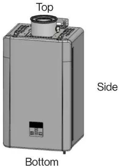
Outdoor (external) units
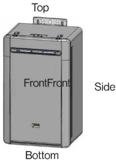
Figure 9: Clearances
Table 7: Clearances
Indoor units
| Location | Clearances To Combustibles and Non-Combustibles |
| Top 2 in. (51 mm) | 0 in. from vent components |
| Bottom/Ground 12 | in. (305 mm) |
| Front (Panel) 0 in. | The clearance for servicing is 24 inches (610 mm) in front of the water heater.For closet installation, clearance is 6 inches (152 mm) from the front of the water heater. |
| Back 0 in. | |
| Sides(Left and Right) | 2 in. (51 mm) |
| Vent | 0 in. |
Outdoor units
| Location | Clearances To Combustibles and Non-Combustibles |
| Top 2 in. (51 mm) | |
| Bottom/Ground 12 | in. (305 mm) |
| Front (Panel) 0 in. | The clearance for servicing is 24 inches in front of the water heater.Do not block the combustion air openings. |
| Back 0 in. | |
| Sides(Left and Right) | 2 in. (51 mm)0.125 in. (3.18 mm) for recess box. |
| Front (Exhaust) 24 | in. (610 mm) |
Do not install this water heater under an overhang less than 3 ft. (91.4 cm) from its top. The area under the overhang must be open on three sides.
CAUTION
If clearances are not met, damage to the property and water heater may occur.
4.3.7 Installation Location Checklist
Use this checklist to ensure you have selected the correct location for the water heater.
| ☐ | The water heater is not exposed to corrosive compounds in the air. |
| ☐ | The water heater location complies with the required clearances. |
| ☐ | For indoor models, the planned venting will not exceed the maximum length for the number of elbows used. |
| ☐ | The planned venting termination/air intake location meets the clearances. |
| ☐ | Indoor air is not being used for combustion. |
| ☐ | The water supply does not contain chemicals or exceed total hardness that will damage the heat exchanger. |
| ☐ | A standard 3 prong 120 V AC, 60 Hz properly grounded wall outlet for indoor models or other 120 V AC, 60 Hz source is available. |
| ☐ | The installation must conform with local codes or, in the absence of local codes, with the National Fuel Gas Code, ANSI Z223.1/NFPA 54, or the Natural Gas and Propane Installation Code, CSA B149.1. If installed in a manufactured home, the installation must conform with the Manufactured Home Construction and Safety Standard, Title 24 CFR, Part 3280 and/or CAN/SCA Z240 MH Series, Mobile Homes. |
| ☐ | Leave the entire manual taped to the water heater or give the entire manual directly to the consumer. |
4.4 Mount the Water Heater to the Wall
4.4.1 Instructions for Indoor Models
You Will Need:
• Rinnai Tankless Water Heater
Supplied by Installer:
- Level
- Screws for top and bottom bracket installation
Use appropriate screws for type of wall construction.
Instructions:
- Identify the installation location and confirm that the installation will meet all required clearances.
- Securely screw the top and bottom brackets into the wall, making sure the screws are flush with the wall.
- Use any of the holes in the top and bottom brackets.
- Use a level (placed horizontally or vertically) to make sure the water heater is straight. Proper operation requires the water heater to be level.
- Make sure the securing method is sufficient to support the weight of the water heater. Refer to the water heater weight in section "3.3 Specifications."
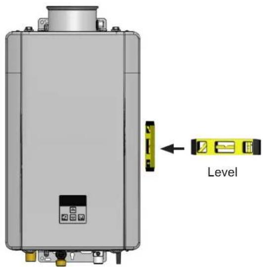
Figure 10: Indoor Models
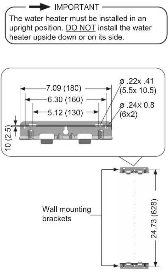
Figure 11: Indoor Mounting Brackets
For installation flexibility, the top and bottom brackets can be adjusted to set the water heater distance from the wall.
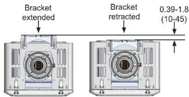
Figure 12: Top View Bracket
4.4.2 Instructions for Outdoor Models
You Will Need:
• Rinnai Tankless Water Heater
Supplied by Installer:
- Level
- Screws for top and bottom bracket installation
Use appropriate screws for type of wall construction.
Instructions:
- Identify the installation location and confirm that the installation will meet all required clearances.
- Securely screw the top and bottom brackets into the wall, making sure the screws are flush with the wall.
- Use any of the holes in the top and bottom brackets.
- Use a level (placed horizontally or vertically) to make sure the water heater is straight. Proper operation requires the water heater to be level.
- Make sure the securing method is sufficient to support the weight of the water heater. Refer to the water heater weight in section "3.3 Specifications."
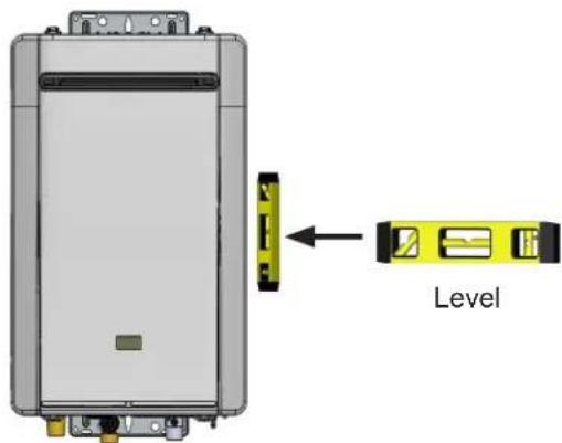
Figure 13: Outdoor Models
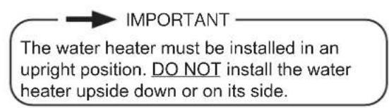
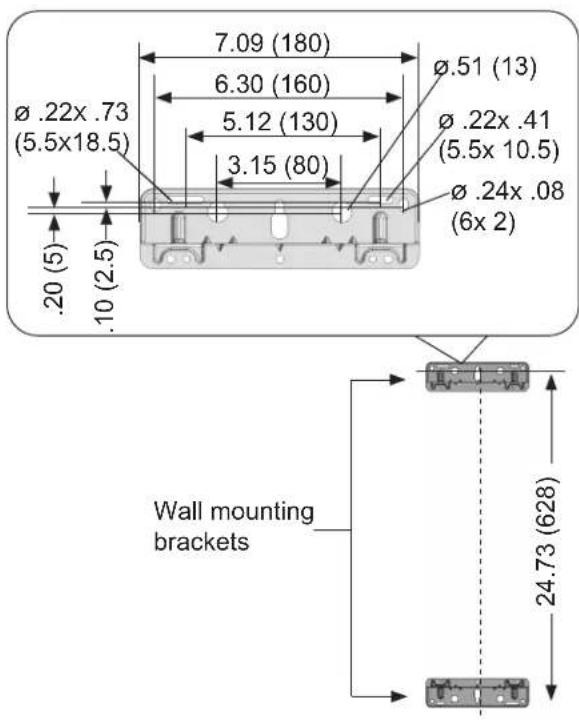
Figure 14: Outdoor Mounting Brackets
4.5 Vent the Water Heater
4.5.1 Guidelines
- This water heater is a direct vent water heater and therefore is certified and listed with the vent system. You must use vent components that are certified and listed with this water heater model.
- The vent system must vent directly to the outside of the building and use outside air for combustion.
• Refer to Table 9: Approved Vent Products for the certified and listed vent components. - Avoid dips or sags in horizontal vent runs by installing supports per the vent manufacturer's instructions.
- Support horizontal vent runs every 4 ft (1.2 m) and all vertical vent runs every 6 ft (1.83 m) or as per vent manufacturer's instructions or local code requirements.
- Venting should be as direct as possible with a minimum number of pipe fittings.
- For manufactured vent systems, vent connections must be firmly pressed together so that the connections form an air tight seal. Follow the venting manufacturer's instructions.
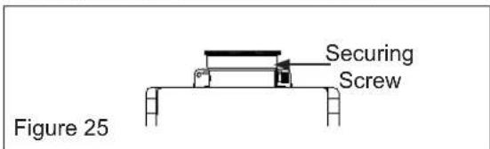
- The vent piece connected to the water heater must be secured with 1 self-tapping screw.
- Refer to the instructions of the vent system manufacturer for component assembly instructions.
- If the vent system is to be enclosed, it is suggested that the design of the enclosure shall permit inspection of the vent system. The design of such enclosure shall be deemed acceptable by the trained and qualified professional or the local inspector.
- Any issues resulting from improper vent installation will not be covered by warranty.

WARNING
- DO NOT use PVC, CPVC, ABS or galvanized material to vent this appliance.
- DO NOT combine vent components from different manufacturers.
• DO NOT reduce the vent diameter. - DO NOT connect the venting system with an existing vent or chimney.
- DO NOT common vent with the vent pipe of any other manufacturer's water heater or appliance.

IMPORTANT
If reusing existing venting it should be inspected for damage and to ensure it is appropriate (approved) for this water heater. To ensure safe and proper operation, damaged vent components MUST be replaced before operating the water heater.
4.5.2 Termination Considerations
Check to determine whether local codes supersede the following clearances:
- Avoid termination locations near a dryer vent.
- Avoid termination locations near commercial cooking exhaust.
- You must install a vent termination at least 12 inches above the ground.
Important considerations for locating vent termination under a soffit (ventilated or unventilated or eave vent; or to a deck or porch)
- DO NOT install vent termination under a vented soffit that may result in exhaust gases entering the soffit vent.
• Install vent termination such that exhaust and rising moisture will not collect under eaves. Discoloration to the exterior of the building could occur if installed too close.
• DO NOT install the vent termination too close under the soffit where it could present recirculation of exhaust gases back into the combustion air intake part of the termination.
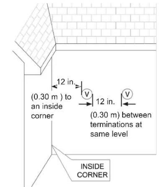
Figure 15
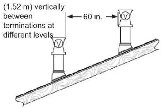
Figure 16
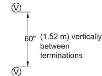
Figure 17
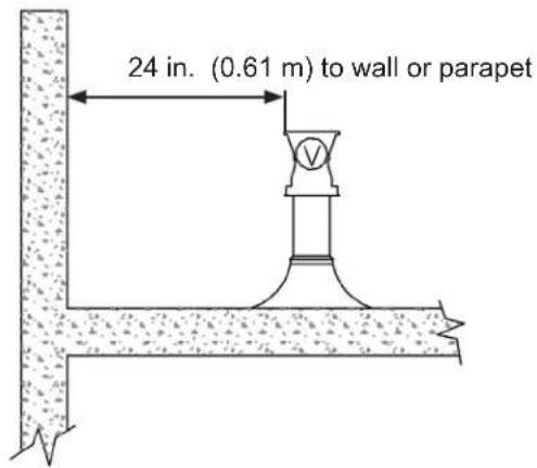
Figure 18
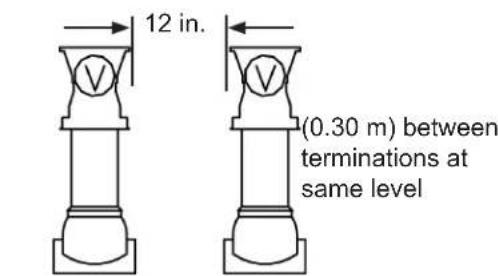
Figure 19
4.5.3 Direct Vent (Indoor): Concentric Pipe
Approved Vent Manufacturers and Products
Following is a list of vent components and terminations for Direct Vent installations. Install the correct venting for your model according to the venting manufacturer's instructions and the guidelines below. The information below is correct at time of publication and is subject to change without notice. Contact the vent manufacturer for questions related to the vent system, products, part numbers and instructions.
Table 8: Approved Vent Manufacturers
| Manufacturer Phone Web Site | ||
| Ubbink 800-621-9419 | www.rinnai.us | |
| Heat-Fab 800-772-0739 | www.heatfab.com | |
| Metal Fab 800-835-2830 | www.metal-fabinc.com | |
Table 9: Approved Vent Products
| Manufacturer | Manufacturer Part number | Product Description | Diagram | Horizontal | Vertical | Equivalent Length (ft) |
| 3 in. /5 in. CONCENTRIC VENT TERMINATIONS | ||||||
| UBBINK | 223181223182 | Termination Kit 11.5 in.Termination Kit 21 in. | 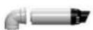 | √ | 10 | |
| 223184 Wall Terminal 21 in. | 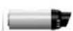 | √ | 5 | |||
| 223187 | 21 in. Non-Condensing Horizontal Termination Diverter Kit |  | √ | 16 | ||
| 224046 Raised Horizontal Termination Kit (Snorkel) | 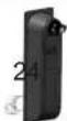 | √ | ||||
| 184118-S184119 | Roof Discharge Termination 18 in.Roof Discharge Termination 38 in. | [ZWZ] | √ | 5 | ||
| HEAT-FAB | SC03HT | Horizontal Termination Adapter | 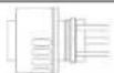 | √ | 20 | |
| SC03VT | Vertical Termination Adapter |  | √ | 20 | ||
| METAL-FAB | 3CGRLSV | Vertical Adapter |  | √ | 1 | |
| 3CGRLSH | Horizontal Adapter |  | √ | 6 | ||
| 3CGRVT | Vertical Termination | [A3SG] | √ | 5 | ||
| 3CGRHT | 3 in. x 5 in. Vertical Termination Cap Kit-Concentric | [ZGKG] | √ | 16 | ||
4.5.4 Direct Vent (Indoor): Termination Clearances
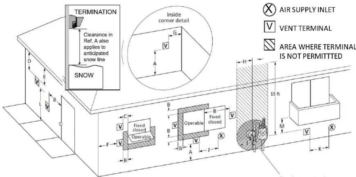
Figure 20: Direct Vent Termination Clearances
Table 10
| U.S. Installations ^1 (ANSI Z223.1/NFPA 54) | ||
| Ref | Description Direct Vent (Indoor Unit) | |
| A | Clearance above grade, veranda, porch, deck, or balcony 12 in. (30 cm) | |
| B | Clearance to window or door that may be opened 12 in. (30 cm) | |
| C | Clearance to permanently closed window * | |
| D | Vertical clearance to ventilated soffit, located above the terminal within a horizontal distance of 2 ft (61 cm) from the center line of the terminal | * |
| E | Clearance to unventilated soffit * | |
| F | Clearance to outside corner * | |
| G | Clearance to inside corner | 12 in. |
| H | Clearance to each side of center line extended above meter/regulator assembly | *. |
| I | Clearance to service regulator vent outlet | * |
| J | Clearance to non-mechanical air supply inlet to building or the combustion air inlet to any other appliance | 12 in. (30 cm) |
| K | Clearance to a mechanical air supply inlet | 3 ft (91 cm) above if within 10 ft (3 m) horizontally |
| L | Clearance above paved sidewalk or paved driveway located on public property | Vents for Category II and IV appliances cannot be located above public walkways or other areas where condensate or vapor can cause a nuisance or hazard. |
| M | Clearance under veranda, porch, deck, or balcony | * |
Notes: ^1 In accordance with the current ANSI Z223.1/NFPA 54, National Fuel Gas Code.
| Clearance to opposite wall is 24 in. (60 cm). | |
| [1] A vent shall not terminate directly above a sidewalk or paved driveway that is located between two single family dwellings and serves both dwellings.[2] Permitted only if veranda, porch, deck, or balcony is fully open on a minimum of two sides beneath the floor. | *Clearances are in accordance with local installation codes and the requirements of the gas supplier. |
If locally adopted installation codes specify clearances different than those illustrated, then the most stringent clearance shall prevail.
4.5.5 Maximum Vent Length
(indoor models only)
- Determine the number of 90 degree elbows in the vent system. (Two 45 degree elbows count as one 90 degree elbow.)
- Refer to the table to find the maximum vent length based on the number of elbows.
Table 11
| Number of 90° elbows | Long (99-R) Short (99- b) | |
| 0 | 21-41 ft(6.4-12.5 m) | 0-20 ft(0-6 m) |
| 1 | 16-35 ft(4.9-10.7 m) | 0-15 ft(0-4.6 m) |
| 2 | 9-29 ft(2.7-8.8 m) | 0-9 ft(0-2.8 m) |
| 3 23 ft (7.0 m) | ||
| 4 17 ft (5.2 m) | ||
| 5 11 ft (3.4 m) | ||
| 6 5 ft (1.5 m) | ||
See "Parameter Settings Table" in section 4.10 for more information.
4.5.6 Venting Installation
(indoor models only)
Install the venting termination according to the diagrams and instructions below.
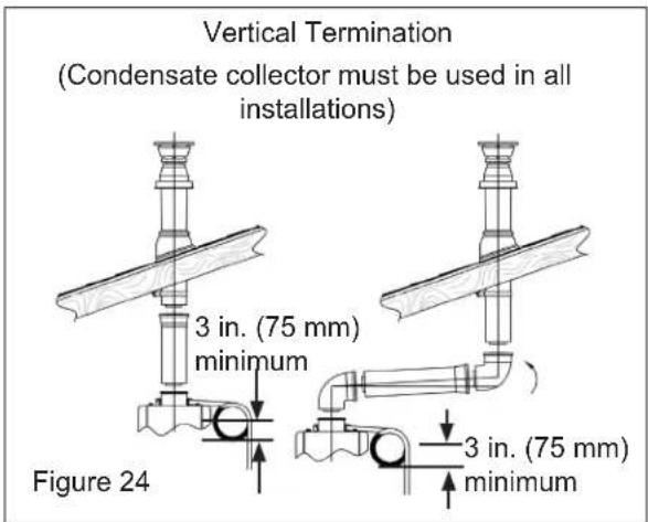
Horizontal Termination using the Condensate Collector
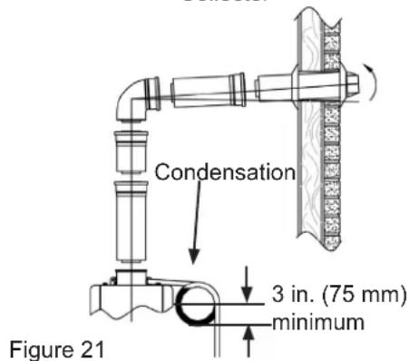
Slope the venting 1/4 in. per foot toward the appliance according to the vent manufacturers installation instructions. Dispose of condensate per local codes.
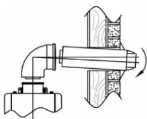
Horizontal Termination without using the Condensate Collector
WARNING
If the condensate collector is not used, the supplied cap must remain installed to prevent exhaust gases and condensate from entering the building. The cap is supplied on the appliance. In such an instance slope the venting 1/4 in. per foot away from appliance according to vent manufacturer's installation instructions.
natural_image
Technical diagram of a mechanical assembly with pipe connection and cross-section showing internal components (no text or labels)Figure 22
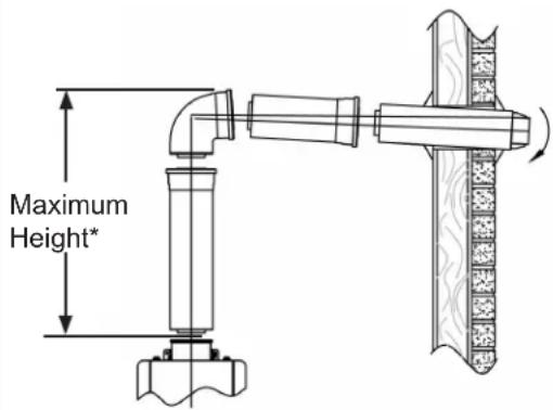
Figure 23
* The condensate collector must be used in horizontal terminations if a vertical rise in the vent system exceeds 5ft.
Regions of cold climate will create more condensate in the vent system. The condensate collector should be used in cold climates.
If more than one elbow is used in the vertical section the condensate collector must be used.
To adjust the condensate collector position: Loosen the 4 screws at the rear bracket
- Slide the bracket away from the female vent top.
- Remove the 4 screws attaching the female vent top to the water heater.
- Lift up the female vent top and reposition as desired.
- Install the 4 screws at the vent top and tighten the 4 screws at the bracket.
- Secure the first vent component to the water heater with one self-tapping screw at the hole located above the condensate collector.
4.5.7 Condensate
(Indoor models only)
Condensate can form in the vent of high efficiency direct vent appliances. Without proper drainage, condensate will damage the heat exchanger.
To prevent condensate damage, follow these instructions.
DO NOT
- DO NOT allow condensate to enter the water heater.
- DO NOT connect the condensate drain pipe directly to the rain sewer.
- DO NOT connect the condensate drain line with an air conditioning evaporator coil drain or.
- DO NOT connect the condensate drain line to the pressure relief valve/line of the appliance.
Must Do
- Use only venting that is approved and identified as acceptable for your particular model.
- For vertical terminations, use the integrated condensate collector and install a condensate trap.
- Slope the venting toward the appliance according to the vent manufacturer's installation instructions.
- All condensate must drain and be disposed of according to local codes.
- Use only corrosion resistant materials for the condensate drain lines such as PVC pipe or plastic hose.
- The condensate drain pipe (along its entire length) must be at least the same diameter as the drain line, (5/8 inch).
- The end of the condensate drain pipe should be open to the atmosphere. The end should not be under water or other substances.
- To minimize freezing of the condensate, run the condensate drain line through an interior wall or between insulation and an interior wall.
- The condensate collector should be used for all combination domestic/hydronic heating applications.
Information
- A condensate trap is available (part number 222053).
- Regions of cold climate will create more condensate in the vent system. The condensate collector should be used in cold climates.
- The condensate drain pipe should be as short as possible and have a downward pitch.
4.5.8 Other than Direct Vent (Outdoor): Termination Clearances
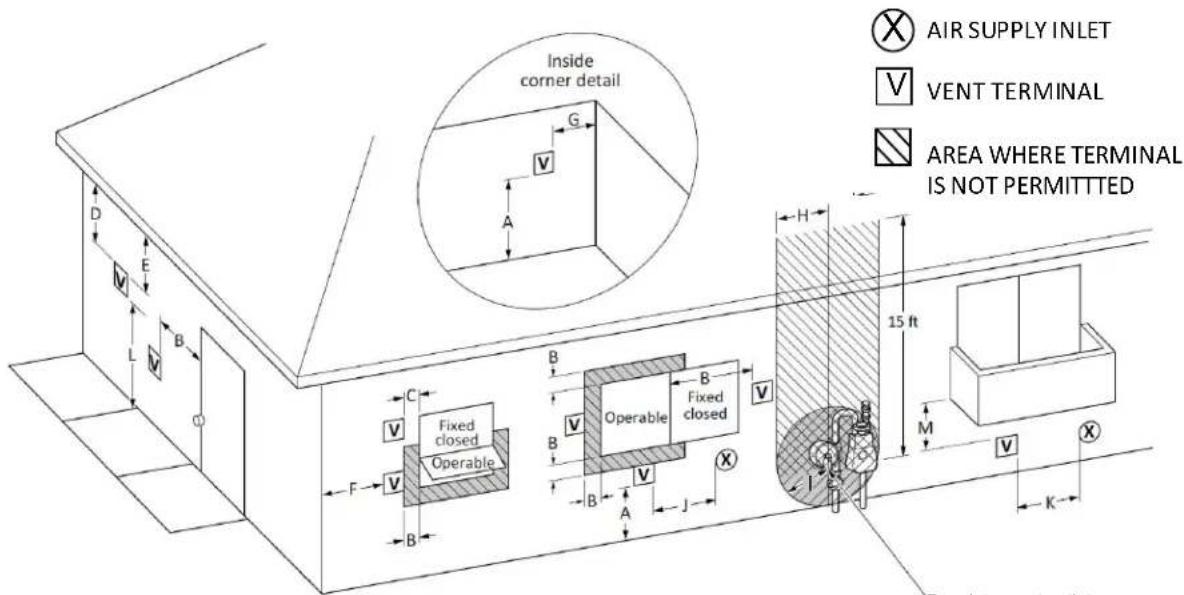
Figure 26: Outdoor Termination Clearances
Table 12
| U.S. Installations ^1 (ANSI Z223.1/NFPA 54) | ||
| Ref | Description Other than direct vent | (Outdoor unit) |
| A C | Clearance above grade, veranda, porch, deck, or balcony 12 in. (30 cm) | |
| B C | Clearance to window or door that may be opened | 4 ft (1.2 m) below or to side of opening; 1 ft (300 mm) above opening |
| C C | Clearance to permanently closed window * | |
| D V | Vertical clearance to ventilated soffit, located above the terminal within a horizontal distance of 2 ft (61 cm) from the center line of the terminal | * |
| E C | Clearance to unventilated soffit * | |
| F C | Clearance to outside corner * | |
| G C | Clearance to inside corner 12 in. | |
| H C | Clearance to each side of center line extended above meter/regulator assembly | * |
| I | Clearance to service regulator vent outlet * | |
| J | Clearance to non-mechanical air supply inlet to building or the combustion air inlet to any other appliance | 4 ft (1.2 m) below or to side of opening; 1 ft (300 mm) above opening |
| K C | Clearance to a mechanical air supply inlet | 3 ft (91 cm) above if within 10 ft (3 m) horizontally |
| L C | Clearance above paved sidewalk or paved driveway located on public property | Vents for Category II and IV appliances cannot be located above public walkways or other areas where condensate or vapor can cause a nuisance or hazard. |
| M | Clearance under veranda, porch, deck, or balcony | * |
Notes: ^1 In accordance with the current ANSI Z223.1/NFPA 54, National Fuel Gas Code.
| Clearance to opposite wall is 24 in. (60 cm). | |
| [1] A vent shall not terminate directly above a sidewalk or paved driveway that is located between two single family dwellings and serves both dwellings.[2] Permitted only if veranda, porch, deck, or balcony is fully open on a minimum of two sides beneath the floor. | *Clearances are in accordance with local installation codes and the requirements of the gas supplier. |
If locally adopted installation codes specify clearances different than those illustrated, then the most stringent clearance shall prevail.
36 inches minimum from the top of the water heater to the overhang. The area under the overhang must be open on 3 sides
4.5.9 Termination Clearances for External (Outdoor) Water Heaters
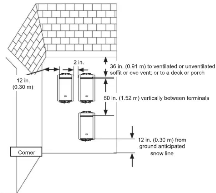
Figure 27
4.5.10 Adjustment for High Altitude Installations
Use parameter settings to select the appropriate altitude for your installation. The default setting for the appliance is 0-2,000 ft. (0-610 m), Parameter Setting 2A. Refer to section "4.10.1 Configure Parameter Settings" for specific details on setting parameters..
| Altitude Parameter Setting | |
| 0-2,000 ft (0-610 m) 02A | |
| 2,001-5,400 ft (610-1,646 m) 02b | |
| 5,401-7,700 ft (1,646-2,347 m) 02C | |
| 7,701-10,200 ft (2,347-3,109 m) 02d | |
Checklist for Venting Requirements
| ☐ | DO NOT use room air for combustion. |
| ☐ | Installation complies with National Fuel Gas Code, ANSI Z223.1/NFPA 54 as well as local and state regulations therein. |
| ☐ | For indoor models verify that the parameters have been adjusted for vent length if necessary. Refer to the section on Maximum Vent Length. |
| ☐ | Confirm high altitude settings are correct for installation location requirements. See Parameter Settings Table for more information. |
4.6 Connect Water Supply
4.6.1 Guidelines
- The piping (including soldering materials) and components connected to this appliance must be approved for use in potable water systems.
- Purge the water line to remove all debris and air. Debris will damage the water heater.
- The appliance must not be connected to a system that was previously used with a non-potable water heating appliance.
- Ensure that the water filter on the water heater is clean and installed.
- Verify water pressure meets requirements.
- DO NOT introduce toxic chemicals such as those used for boiler water treatment to the potable water used for space heating.
4.6.2 Instructions
To connect the water supply, follow the instructions below.

IMPORTANT
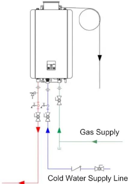
Water connections to the water heater should follow all state and local plumbing codes. If this is a standard installation, refer to the “Piping Diagram for Basic Installation” below.
- Plumb the cold water supply line to the water heater on the 3/4 in. MNPT connection at the bottom of the water heater marked "C."
- Plumb the hot water supply line to the 3/4 in. MNPT connection marked "H."
- If a pipe cover will be installed, make sure water lines to the water heater fit within the confinements of the pipe cover.
PIPING DIAGRAM FOR BASIC INSTALLATION
The condensate drain pipe (along its entire length) must be at least the same diameter as the drain line (1/2 in. NPT).
KEY

3/4" Ball Valve

Pressure Regulator

3/4" Union

Circulating Pump

Check Valve

Boiler Drain Valve

Pressure Relief Valve

Solenoid Valve
This is not an engineered drawing. It is intended only as a guide and not as a replacement for professionally engineered project drawings. This drawing is not intended to describe a complete system. It is up to the contractor/engineer to determine the necessary components and configuration of the particular system being installed. This drawing does not imply compliance with local building code requirements. It is the responsibility of the contractor/engineer to ensure installation is in accordance with all local building codes. Confer with local building officials before installation.
flowchart
graph TD
    A["Cold Water Supply Line"] --> B["Gas Supply"]
    B --> C["Control Valve 1"]
    B --> D["Control Valve 2"]
    B --> E["Control Valve 3"]
    B --> F["Control Valve 4"]
    B --> G["Control Valve 5"]
    B --> H["Control Valve 6"]
    B --> I["Control Valve 7"]
    B --> J["Control Valve 8"]
    B --> K["Control Valve 9"]
    B --> L["Control Valve 10"]
    style A fill:#f9f,stroke:#333
    style B fill:#ccf,stroke:#333
    style C fill:#cfc,stroke:#333
    style D fill:#fcc,stroke:#333
    style E fill:#cff,stroke:#333
    style F fill:#ffc,stroke:#333
    style G fill:#cfc,stroke:#333
    style H fill:#fcc,stroke:#333
    style I fill:#cfc,stroke:#333
    style J fill:#fcc,stroke:#333
    style K fill:#cfc,stroke:#333
    style L fill:#fcc,stroke:#333
Hot Water Supply Line
Figure 28
4.7 Install Pressure Relief Valve
WARNING
Water discharged from the pressure relief valve could cause severe burns instantly or death from scalds.
4.7.1 Guidelines
An approved pressure relief valve is required by the American National Standard (ANSI Z21.10.3) for all water heating systems and shall be accessible for servicing. When connecting a pressure relief valve, follow the guidelines below:
- The pressure relief valve must comply with the standard for Relief Valves and Automatic Gas Shutoff Devices for Hot Water Supply Systems ANSI Z21.22 and /or the standard Temperature, Pressure, Temperature and Pressure Relief Valves and Vacuum Relief Valves, CAN1-4.4.
- The pressure relief valve must be rated up to 150 psi and to at least the maximum Btu/hr of the appliance.
- The discharge from the pressure relief valve should be piped to the ground or into a drain system per local codes.
- The pressure relief valve must be manually operated once a year to check for correct operation.
- The discharge line from the pressure relief valve should pitch downward and terminate 6 in. (152 mm) above drains where discharge will be clearly visible.
- The discharge end of the line shall be plain (unthreaded) and a minimum of 3/4 in. nominal pipe diameter. The discharge line material must be suitable for water at least 180^ .
- The pressure relief valve is connected below the appliance. DO NOT place any other valve or shut off device between the pressure relief valve and the water heater.
- If a pressure relief valve discharges periodically, this may be due to thermal expansion in a closed water supply system. Contact the water supplier or local plumbing inspector on how to correct
this situation. DO NOT plug the pressure relief valve.
- The American National Standard (ANSI Z21.10.3) does not require a combination temperature and pressure relief valve for this appliance. However, local codes may require a combination temperature and pressure relief valve.
- Protect pressure relief valve and pressure relief valve discharge line from freezing. Do not plug or restrict flow of the pressure relief valve.
- DO NOT plumb the pressure relief valve with the condensate drain; both must be plumbed independently to drain.
- DO NOT plug the pressure relief valve and do not install any reducing fittings or other restrictions in the relief line. The pressure relief line should allow for complete drainage of the valve and the line.
- DO NOT place any other valve or shutoff device between the pressure relief valve and the water heater.
Pressure Relief Valve Maintenance:
For proper care of this approved pressure relief valve, it is recommended that the valve is manually operated once a year. In doing so, it will be necessary to take precautions with regard to the discharge of potentially scalding hot water under pressure. Ensure discharge water has a safe place to flow. Contact with your body or other property may cause damage or harm.
4.8 Connect the Gas Supply

WARNING
- A trained and qualified professional must install the gas supply.
- Confirm the gas type before connecting. Failure to install correct gas type may result in injury or damage to the unit.
- Turn off 120V power supply.
- Turn off the gas.
- Gas is flammable. DO NOT smoke or provide other ignition sources while working with gas.
- DO NOT turn on the water heater or gas until all fumes are gone.
4.8.1 Instructions
To connect the gas supply, follow the instructions below:
- Install a manual shutoff (control) valve in the gas supply line to the water heater. A union can be used on the connection above the shut off valve for the future servicing or disconnection of the water heater.
- Check the type of gas and gas supply pressure before connecting the water heater. If the water heater is not of the gas type that the building is supplied with, DO NOT connect the water heater. Contact the dealer for the proper water heater to match the gas type.
- Check the gas supply pressure immediately upstream at a location provided by the gas company. Supplied gas pressure must be within the limits shown in section "3.3 Specifications" with all gas appliances operating. Install a proper gas regulator upstream of a water heater if a supply gas pressure is too high.
- Before placing the appliance in operation, all joints including the heater must be checked for gas tightness by means of soap, gas leak detector solution, or an equivalent
nonflammable solution, as applicable. (Since some leak test solutions, including soap and water, may cause corrosion or stress cracking, the piping shall be rinsed with water after testing, unless it has been determined that the leak test solution is non-corrosive.)
-
Use approved connectors to connect the water heater to the gas line. Purge the gas line of any debris before connection to the water heater.
-
Any compound used on the threaded joint of the gas piping shall be a type that resists the action of liquefied petroleum gas (propane/LPG).
-
The gas supply line shall be gas tight, sized, and so installed as to provide a supply of gas sufficient to meet the maximum demand of the heater and all other gas consuming appliances at the location without loss of pressure. If in doubt about the size of the gas line, refer to the "Gas Pipe Sizing Reference Tables" section on the next page.
-
Perform a leak and pressure test prior to operating the water heater. If a leak is detected, do not operate the water heater until the leak is repaired.
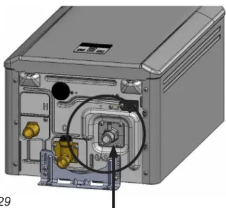
natural_image
3D diagram of an internal device showing ports, cables, and a connector (no text or labels visible)Figure 29
Gas connection 3/4 in.
MNPT connection
4.8.2 Gas Pipe Sizing Reference Tables
The gas supply must be capable of handling the entire gas load required at the location. Gas line sizing is based on gas type, the pressure drop in the system, the gas pressure supplied, and gas line type. For gas pipe sizing, refer to the National Fuel Gas Code, ANSI Z223.1/NFPA 54.
For some tables, you will need to determine the cubic feet per hour of gas required by dividing the gas input by the heating value of the gas (available from the local gas company). The gas input needs to include all gas products at the location and the maximum Btu usage at full load when all gas products are in use.
Use the table for your gas type and pipe type to find the pipe size required. The pipe size must be able to provide the required cubic feet per hour of gas or the required Btu/hour.
The information below is provided as an example. The appropriate table from the applicable code must be used.
Table 13: Gas Pipe Sizing Calculation Worksheet
Instructions: Enter values in empty boxes.
Rinnai Model Gas Input:

Additional Appliance Total Gas Input:

Heating Value of Gas:

Cubic Feet Per Hour (CFH):
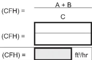
Answer:
Natural Gas
| Table 14: Pressure Drop 0.3 in. wc | ||||
| Information in table obtained from NFPA 54, ANSI Z223.1 | Schedule 40 Metallic Pipe | |||
| Inlet Pressure: | Less than 2 psi | |||
| Specific Gravity: | 0.60 | |||
| Nominal Pipe Size (in.) | ||||
| 3/4 1 1 | 1/4 1 1/2 | |||
| Length in ft (meters) | Capacity in Cubic Feet of Gas per Hour | |||
| 10 (3) 273 | 514 | 1,060 | 1,580 | |
| 20 (6) | 188 | 353 | 726 | 1,090 |
| 30 (9) 151 | 284 | 583 | 873 | |
| 40 (12) 129 | 243 | 499 | 747 | |
| 50 (15) | 114 | 215 | 442 | 662 |
| 60 (18) 104 | 195 | 400 | 600 | |
| 70 (21) | 95 | 179 | 368 | 552 |
| 80 (24) | 89 | 167 | 343 | 514 |
| 90 (27) | 83 | 157 | 322 | 482 |
| 100 (30) | 79 | 148 | 304 | 455 |
| Table 15: Example | ||
| Rinnai Model Gas Input: | ||
| A | 199,000 | Btu/hr |
| Additional Appliance Total Gas Input: | ||
| B | 65,000 | Btu/hr |
| Heating Value of Gas: | ||
| C | 1,000 | Btu/ft3 |
| Cubic Feet Per Hour (CFH): | ||
| (CFH) = | A + B | C |
| (CFH) = | 199,000+65,000 | 1,000 |
| Answer: | ||
| (CFH) = | 264 | ft3/hr |
| For this example, the pipe diameter must be at least 3/4 in. pipe size and 10 ft (3 m) in length. | ||
Propane (Undiluted)
| Table 16: Pressure Drop 0.5 in. wc | ||||
| Information in tableobtained from NFPA 54,ANSI Z223.1 | 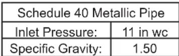 | |||
| Nominal Pipe Size (in.) | ||||
| 1/2 3/4 | 1 1 1/4 | |||
| Length in ft(meters) | Capacity in Thousands of Btu per Hour | |||
| 10 (3) 291 608 | 1,150 | 2,350 | ||
| 20 (6) 200 418 | 787 | 1,620 | ||
| 30 (9) 160 336 | 632 | 1,300 | ||
| 40 (12) 137 | 287 | 541 | 1,110 | |
| 50 (15) 122 | 255 | 480 | 985 | |
| 60 (18) | 110 | 231 | 434 | 892 |
| 80 (24) 101 | 212 | 400 | 821 | |
| 100 (30) 94 | 197 | 372 | 763 | |
Table 17: Example
Rinnai Model Gas Input:
| A | 199,000 | Btu/hr |
Additional Appliance Total Gas Input:
| B | 65,000 | Btu/hr |
Total Gas Input:
| Total Gas Input | = | A + B |
| Total Gas Input | = | 199,000 + 65,000 |
Answer:
| Total Gas Input = 264,000 Btu/hr |
For this example, the pipe diameter must be at least 1/2 in. nominal pipe size and 10 ft (3 m) in length.
4.9 Connect the Power Supply

WARNING
- DO NOT use an extension cord or adapter plug with this appliance.
- The water heater must be electrically grounded in accordance with local codes and ordinances or, in the absence of local codes, in accordance with the National Electrical Code, ANSI/NFPA No.70.
- Indoor water heaters are equipped with a three-prong (grounding) plug for your protection against shock hazard and should be plugged directly into a properly grounded three-prong receptacle. DO NOT cut or remove the grounding terminal from this plug.
4.9.1 Guidelines
When connecting the power supply, follow these guidelines:
- DO NOT rely on the gas or water piping to ground the water heater. Ground locations are provided inside the water heater.
- The water heater requires 120 V AC, 60 Hz power from a properly grounded circuit.
- If using the 5 ft (1.5 m) power cord (supplied with internal/indoor water heaters), plug it into a standard 3 prong 120 V AC, 60 Hz properly grounded wall outlet.
- On external (outdoor) models, a proper disconnect (i.e. on/off switch, power cord, etc.) must be provided and installed for the incoming 120 V AC power. The switch should be a type that is suitable for outdoor use. Check the National Electrical Code, ANSI/NFPA 70 and your local codes for a proper switch type to use in your area. Power connections must be protected from the weather and flexible cords must use an appropriate strain relief.
- The wiring diagram is located on the inside of the water heater front cover.
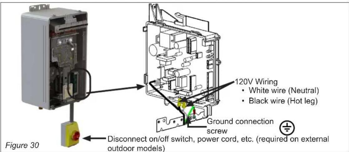
Checklist for Gas and Power Supply
| ☐ | A manual gas shutoff (control) valve is located in the gas line to the water heater. |
| ☐ | Check the gas lines and connections for leaks. |
| ☐ | Confirm that the gas inlet pressure is within limits. |
| ☐ | Confirm that the water heater is rated for the gas type supplied. |
| ☐ | Confirm that the electricity is supplied from 120 V AC, 60 Hz power source and is in a properly grounded circuit. |
| ☐ | Confirm an extension cord or an adapter plug has not been used with the water heater. |
4.10 Configure Parameter Settings
4.10.1 Instructions
WARNING
DO NOT adjust parameter settings unless specifically instructed to do so.
To adjust the parameters:
- Locate the PC Board (lower right side of unit).
- Locate the two push buttons (A and B) on the PC Board.
-
Press the "A" button for 1 second.
-
Use the ▲ (Up) and ▼ (Down) buttons on the controller to select a setting number (see Parameter Settings Table below).
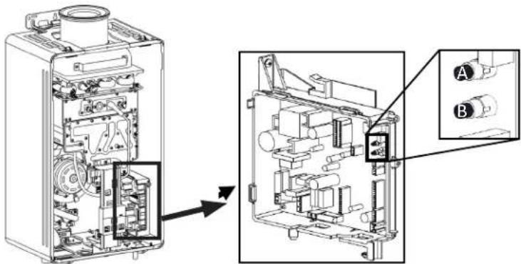
Figure 31
- Once the desired setting number is selected, use the "On/Off" button on the controller to change the selection for the setting number.
Example: Display will change from 01A to 01b for Maximum Temperature setting (as shown below).
- To exit the parameters, press the "A" button for 1 second.
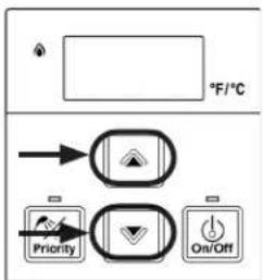
Figure 32

Figure 33
Table 18: Parameter Settings Table
| SETTING # | SETTING DESCRIPTION | SELECTION | |||
| R | b | C | d | ||
| 01 | Maximum Set Temperature | 120°F 140°F | |||
| 02 | High Altitude Installation | 0 - 2,000 ft(0 - 610 m) | 2,001 - 5,400 ft(610 - 1,646 m) | 5,401 - 7,700 ft(1,646 - 2,347 m) | 7,701 - 10,200 ft(2,347 - 3,109 m) |
| 03 | Service Soon Disapled 0.5 Year 1 Year 2 Years | ||||
| 04 | Recirculation Settings | No Recirculation | Recirculation (Dedicated) | ||
| 05 | Recirculation Mode Economy Comfort | ||||
| 06 | Control Switch | BMS | Air Handler (AH) | ||
| 07 | Units in Standby | 2 | 1 | ||
| 10 | Gas Type | LPG | NG | ||
| 12 | Water Heater Model (Factory set values and not adjustable) | Without Pump | With Pump | ||
| 13 | 199/160 | 180/140 | |||
| 14 | Indoor | Outdoor | |||
| 15 | Low Activation Mode | On | Off | ||
| 18 | Setting Temperature Table | Default | Alternate | ||
| 19 | Adjust DHW Temperature Setting | 0°F (0°C) | 1.8°F (1°C) | 3.6°F (2°C) | 5.4°F (3°C) |
| 99 | Vent Length | Long | Short | ||
RE140 does not have recirculation mode.
4.10.2 Service Indicator (Service Soon, 55)
This water heater includes a service indicator (Service Soon, 55). When selected in the parameter settings, an 55 code will display on the controller indicating that it is time to flush and service the water heater.
- Selection is installers preference based on water conditions or other factors that may influence the suggested interval of service.
- See the "Configure Parameter Settings" section of this manual for selectable service intervals.
- If Service Soon (55) appears on the controller display, contact your local service provider to flush and service the water heater (see 6.3 Flushing the Heat Exchanger)
- Service Soon will appear again based on the selected service interval.
To reset Service Soon (55)
Press the ON/OFF button 5 times
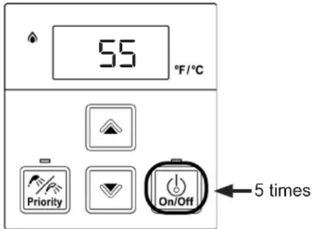
Figure 34
NOTE: Service Soon (55) will display on the controller again when the water heater reaches the interval selected in the parameter settings.
4.11 Recirculation
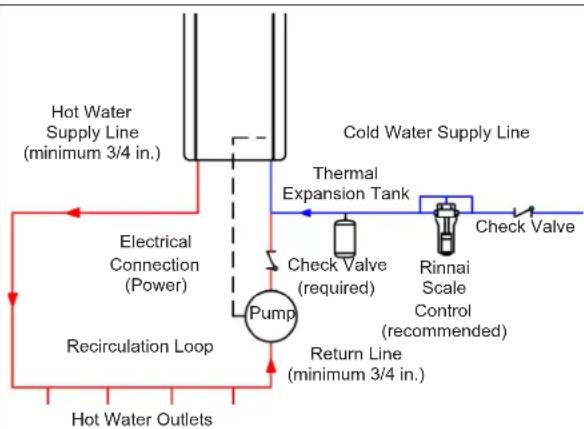
Including recirculation can reduce the amount of time it takes hot water to get to your fixture. This model water heater includes the ability to control a recirculation pump. Two modes are available, Economy and Comfort.
- Economy Mode—Cycles the pump less often, using less energy to maintain the circulation loop temperature.
- Comfort Mode—Cycles the pump more frequently, ensuring the loop temperature remains higher (but also uses more energy).
Recirculation mode is for residential installations only. Recirculation mode cannot be used with an air handler or with multiple Rinnai water heaters.
The maximum Rinnai temperature setting while in recirculation mode is 140^ F ( 60^ C).
Table 19
| Pump Requirements | |
| Voltage 120V, 60 | Hz |
| Max Current Less than 2 Amps | |
| Check valve An in integral flow check (IFC) valve is required. See plumbing diagram. | |
Pump Size
The pump should be sized for 2 - 4 GPM (7.6 - 15.1 LPM) at the pressure loss through the tankless water heater and the supply and return plumbing in the recirculation loop. (Refer to the pressure drop curve in Section 7.4 for more information.)
Installation
- Turn off the electrical power supply by unplugging the power cord or by turning off the electricity at the circuit breaker.
-
Install the recirculation pump on the return line according to the pump manufacturer installation instructions. Install a check valve in the return line as shown in the Plumbing Diagram if one is not integrated into the pump.
-
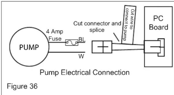
The wire harness for the recirculation pump is bundled with the wire harness from the PC board. The connector has a black and white wire with the label "Cut wire to connect to pump". To connect to the pump, cut the connector, splice the wires, and add 4 Amp fuse to the hot wire (black) of the pump. Connect the ground wire from the pump to a screw at the base of the water cabinet. Refer to the Pump Electrical Connection Diagram. Follow Electrical Code and pump manufacturers recommendations.
-
Connect power to the water heater. Press the Power button on the controller. The pump and water heater will turn on to raise the recirculation loop temperature.
flowchart
graph TD
    A["Hot Water Supply Line (minimum 3/4 in.)"] --> B["Electrical Connection (Power)"]
    B --> C["Pump"]
    C --> D["Return Line (minimum 3/4 in.)"]
    D --> E["Check Valve (required)"]
    D --> F["Rinnai Scale Control (recommended)"]
    D --> G["Check Valve"]
    G --> H["Cold Water Supply Line"]
    H --> I["Thermal Expansion Tank"]
    I --> J["Recirculation Loop"]
    J --> K["Hot Water Outlets"]
NOTE: DO NOT install the Rinnai Scale Control system within the recirculation loop.
Figure 35 Plumbing Diagram
4.12 Post-Water Heater Installation Checklist
Complete the following checklist when water heater installation is complete. You should be able to answer YES to each question. If you answer NO to any question, installation is not complete. Refer to the applicable section in the Rinnai Tankless Water Heater Installation and Operation Manual for additional information.
For assistance, contact your local dealer or distributor, or call Rinnai Customer Care at 1-800-621-9419.
| 1 INSTALLATION LOCATION YES NO | ||
| Have you verified the unit and vent termination meet the clearance requirements? | □ | □ |
| 2 COMBUSTION AIR & VENTING YES NO | ||
| Have all corrosive compounds been removed from around the combustion air inlet of the tankless water heater? | □ | □ |
| Are the correct venting products for the installed model being utilized? | □ | □ |
| Have you verified the vent system does not exceed maximum length? | □ | □ |
| If reusing existing venting, have you inspected the vent components or damages to ensure it is safe for installation? | □ | □ |
| 3 PLUMBING YES NO | ||
| Have the water lines been purged of all debris and the filter cleaned? | □ | □ |
| Have you verified the hot and cold water lines to the tankless water heater are not interchanged? | □ | □ |
| Does the water supply to the heater have adequate pressure? Is it free of chemicals? Did you verify it does not exceed total hardness that will damage the heat exchanger? | □ | □ |
| Have you verified that no toxic chemicals were introduced to the potable water? | □ | □ |
| Have water quality issues (if any) been addressed? | □ | □ |
| Did you drain the tankless water heater if not intended to be used immediately? | □ | □ |
| Have you performed the leak and pressure test for the tankless water heater and plumbing system? | □ | □ |
| 4 ISOLATION VALVES YES NO | ||
| Are isolation valves (accessories) installed? | □ | □ |
| 5 PRESSURE RELIEF VALVE (PRV) YES NO | ||
| Does the PRV comply with the standard for Relief Valves and Automatic Gas Shutoff Devices for Hot Water Supply Systems ANSI Z21.22, and/or the standard Temperature, Pressure, Temperature and Pressure Relief Valves and Vacuum Relief Valves, CAN1-4.4? | □ | □ |
| Did you verify the PRV is rated for no more than 150 psi and (at least) the maximum Btu/hr of the tankless water heater? | □ | □ |
| Is the discharge from the PRV piped to the ground or into a drain system as per local codes? | □ | □ |
| Is the discharge line from the PRV pitched downward and does it terminate 6 in. (152 mm) above the drain? | □ | □ |
| Is the discharge end of the line plain (unthreaded) and a minimum of 3/4 in. diameter? | □ | □ |
| Is the discharge line material suitable for at least 180°F (82°C) water? | □ | □ |
| Did you take measures to protect the PRV and PRV discharge line from freezing? | □ | □ |
| Have you verified the PRV is not plugged and that reducing fittings, valves, or other restrictions are not installed in the relief line? | □ | □ |

GAS SUPPLY YES NO
| Did you verify the gas system is appropriately sized? | □ | □ |
| Did you verify the water heater is rated for the gas type supplied? | □ | □ |
| Have you performed a gas line and connection leak test? | □ | □ |
| Did you install a manual gas control valve in the gas line to the water heater? | □ | □ |
| Is the inlet gas pressure within limits? | □ | □ |
| Did you purge the gas line of air or any debris before connecting the water heater? | □ | □ |
5.5. OperationOperation
Topics in this section
- Safety Precautions
- Operating Instructions
- Control Panel
- Setting the Temperature
• Performance Data - Diagnostic Codes
5.1 Safety Precautions

WARNING
If the information in these instructions is not followed exactly, a fire or explosion may result causing property damage, personal injury, or death.
- DO NOT store or use gasoline or other flammable vapors and liquids in the vicinity of this or any other appliance.
- Before operating, smell all around the appliance area for gas. Be sure to smell next to the floor because some gas is heavier than air and will settle on the floor.
• WHAT TO DO IF YOU SMELL GAS
- DO NOT try to light any appliance.
- DO NOT touch any electrical switch; DO NOT use any phone in your building.
- Immediately call your gas supplier from a neighbor's phone. Follow the gas supplier's instructions.
- If you cannot reach your gas supplier, call the fire department.
• Installation and service must be performed by a trained and qualified professional, service agency or the gas supplier.
- Keep the area around the appliance clear and free from combustible materials, gasoline, and other flammable vapors and liquids.
- DO NOT use this appliance if any part has been under water. Immediately call a trained and qualified professional to inspect the appliance and to replace any part of the control system and any gas control which has been under water.
- Should overheating occur or the gas supply fail to shut off, turn off the manual gas shut-off (control) valve to the appliance.
- Use only your hand to push in or turn the gas control knob. Never use tools. If the knob will not push in or turn by hand, DO NOT try to repair it, call a trained and qualified professional. Force or attempted repair may result in a fire or explosion.
- This appliance does not have a pilot. It is equipped with an ignition device which automatically lights the burner. DO NOT try to light the burner by hand.
- DO NOT use an extension cord or an adapter plug with this appliance.
- Any alteration to the appliance or its controls can be dangerous and will void the warranty.
- If you install this water heater in an area that is known to have hard water or that causes scale build-up the water must be treated and/or the heat exchanger flushed regularly. Rinnai provides a “Scale Control System” that offers superior lime scale prevention and corrosion control by feeding a blend of control compounds into the water supply. Damage and repair due to corrosive compounds in the air is not covered by warranty.
- Keep the combustion air vent pipe location free of chemicals, such as chlorine or bleach, that produce fumes. These fumes can damage components and reduce the life of your appliance. Damage and repair due to scale in the heat exchanger is not covered by warranty.
• Always check the water temperature before entering a shower or bath. - DO NOT adjust the parameters unless specifically instructed to do so.
5.2 Operating Instructions
If you do not follow these instructions exactly, a fire or explosion may result causing property damage, personal injury or loss of life.
A. This appliance does not have a pilot. It is equipped with an ignition device which automatically lights the burner. Do not try to light the burner by hand.
B. BEFORE OPERATING, smell all around the appliance area for gas. Be sure to smell next to the floor because some gas is heavier than air and will settle on the floor.
WHAT TO DO IF YOU SMELL GAS
- Do not try to light any appliance.
- Do not touch any electric switch; do not use any phone in your building.
- Immediately call your gas supplier from a neighbor's phone. Follow the gas
supplier's instructions.
- If you cannot reach your gas supplier, call the fire department.
C. Use only your hand to push in or turn the gas control valve. Never use tools. If the gas control valve will not turn by hand, do not try to repair it, call a qualified service technician. Force or attempted repair may result in a fire or explosion.
D. Do not use this appliance if any part has been under water. Immediately call a qualified service technician to inspect the appliance and to replace any part of the control system and any gas control which has been under water.
OPERATING INSTRUCTIONS
- STOP! Read the safety information above.
- Set the temperature controller to lowest setting.
- Turn off all electric power to the appliance.
- This appliance does not have a pilot. It is equipped with an ignition device which automatically lights the burner. Do not try to light the burner by hand.
- Turn the manual gas control valve located at gas inlet of appliance clockwise to the OFF position.
- Wait five (5) minutes to clear out any gas. Then smell for gas, including near the floor. If
you smell gas, STOP! Follow "B" in the safety information above. If you don't smell gas, go to the next step.
- Turn the manual gas valve located at gas inlet of appliance counterclockwise to the full ON position.
- Turn on all electric power to the appliance.
- Set the temperature controller to desired setting.
- If the appliance will not operate, follow the instructions "To Turn Off Gas To Appliance" and call your service technician or gas supplier.
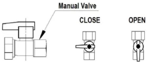
TURN OFF GAS TO APPLIANCE
- Set the temperature controller to lowest setting.
-
Turn off all electric power to the appliance if service is to be performed.
-
Turn the manual gas control valve located at gas inlet of appliance clockwise to the OFF position.
5.3 Control Panel
The water heater includes a controller. For indoor models the controller is integrated into the front cover. For outdoor models, the controller is located inside the front cover.
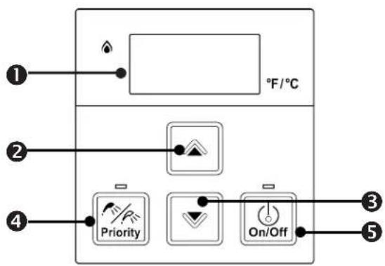
Figure 37
Table 20
| 1 | Display |
| 2 | Increases hot water temperature |
| 3 | Decreases hot water temperature |
| 4 | Enables controller when multiple controllers are used |
| 5 | Turns the water heater on or off |
5.3.1 Setting the Controller to Mute
To eliminate the beeps when keys are pressed, press and hold both the ▲ (Up) and ▼ (Down) buttons at the same time until a beep is heard (approximately 5 seconds). Then, release both buttons.
To turn on the beeps, repeat the above steps.
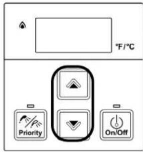
Figure 38
5.3.2 Locking the Controller
- To lock the internal controller, press and hold down the "Priority" button.
- While holding down the "Priority" button, press the ▲ (Up) button until a beep is heard (approximately 5 seconds). Then, release both buttons at the same time.
- LOC appears in the display indicating the controller is locked.
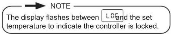
To unlock the controller, follow the above steps.
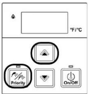
Figure 39
5.4 Setting the Temperature

DANGER
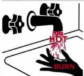
Water temperatures over 125^ F ( 52^ C) can cause severe burns or scalding resulting in death.
Hot water can cause first degree burns with exposure for as little as:
• 3 seconds at 140^ F ( 60^ C)
• 20 seconds at 130°F (54°C)
- 8 minutes at 120^ (49°C)
Children, disabled, or elderly are at highest risk of being scalded.
Feel water before bathing or showering.

IMPORTANT
- Check local codes for the maximum water temperature setting allowed when used in nursing homes, schools, day care centers, and all other public applications.
- If a newly installed water heater with a controller has not been powered for at least 6 hours then the temperature will return to the default setting of if power is interrupted.
- There may be a variation between the temperature displayed on the temperature controller and the temperature at the tap due to weather conditions or the length of pipe to the water heater.
The controller buttons shown below are located on the outside front panel for internal (indoor) water heaters.
For external (outdoor) water heaters, open the front panel to access the controller buttons.
- If the water heater is off, press the "On/Off" button to turn on.
- If multiple controllers are installed the "Priority" button, when selected, will enable that controller to function. Note: Priority can only be changed when hot water is not in use.
- Press the ▲ (Up) or ▼ (Down) buttons to obtain the desired temperature setting.
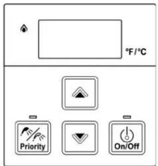
Figure 40
5.4.1 Available Temperatures with an Internal Controller
The water heater can deliver water at only one temperature setting at a time. The available temperatures are provided below. A temperature lower than 98^ F ( 37^ C) can be obtained at the tap by mixing with cold water. To change the temperature scale from Celsius to Fahrenheit or vice versa, press and hold the “On/Off” button on the controller for 5 seconds while the water heater is OFF.
Table 21
| Temperature Settings | |||||||||||||||||
| RE199i/e | °F | 98 | 100 | 102 | 104 | 106 | 108 | 110 | 115 | 120 | 125* | 130* | 135* | 140* | 150** | 160** | 185** |
| RE180i/e | °C | 37 | 38 | 39 | 40 | 41 | 42 | 43 | 46 | 49 | 52 | 54 | 57 | 60 | 66 | 71 | 85 |
| RE160i/e | °F | 120 | 125* | 130* | 135* | 140* | |||||||||||
| RE140i/e | °C | 49 | 52 | 54 | 57 | 60 | |||||||||||
Temperature range depends on model type. Refer to section "3.3 Specifications" for more information.
* These models have a default maximum temperature of 120°F (49°C) and an option to increase the maximum temperature to 140°F (60°C). Refer to section "4.10.1 Parameter settings" for further details.
** These settings require the installation of the MCC-601 controller. When the MCC-601 controller is connected, these higher temperatures are available on all controller models in the system. Use of an MCC-601 controller in a residential dwelling will reduce the warranty coverage to that of a commercial warranty application.
If setting temperature is 185^ F, water pressure should be between 45 and 150 PSI.
Alternate Temperatures Settings
A different range of temperature settings is available by setting parameter settings. The table below shows the settings available with the MC-601 and MCC-601 controller.
WARNING MC-91-1, MCC-91-1, MC-100V-1, and BC-100V-1 controllers are not compatible with Alternate Temperature Settings. Alternate Temperature Settings are for commercial applications. DO NOT use the MC-91-1, MCC-91-1, MC-100V-1, BC-100V-1 controllers when parameter settings are set.
Table 22
| Temperature Settings | |||||||||||||||||
| RE199i/e | °F | 110 | 115 | 120 | 125 | 130 | 135 | 140 | 145 | 150 | 155 | 160 | 165* | 170* | 175* | 180* | 185* |
| RE180i/e | °C | 43 | 46 | 49 | 52 | 54 | 57 | 60 | 63 | 66 | 68 | 71 | 74 | 77 | 79 | 82 | 85 |
| MC-601 | MCC-601 | ||||||||||||||||
* If setting temperature is greater than 165, water pressure should be between 45 and 150 PSI.
5.5 Performance Data
To obtain performance data:
- Press and hold the ▼ (Down) button.
- While holding the ▼ (Down) button for 2 seconds, press and hold the "On/Off" button (hold both buttons simultaneously). (Figure 41)
- Use the ▲ (Up) and ▼ (Down) buttons to scroll to the desired information described in Table 23: Performance Data Table. (Figure 42)
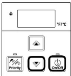
Figure 41 Figure 42
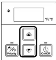
- To exit performance data, repeat step 2 above. (Figure 43)
- When complete, the set temperature appears in the display.
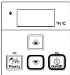
Figure 43
Table 23: Performance Data Table
| # Data Unit | ||
| 01 | Water Flow Rate x0.1 gal/min | |
| 02 | Outgoing Temperature °F | |
| 03 | Combustion Hours x100 Hours | |
| 04 | Combustion Cycles * | |
| 05 | Fan Frequency Hz | |
| 06 | Additional Controllers Connected * | |
| 07 | Water Flow Control Position | 0=Mid 1=Open2=Closed |
| 08 | Inlet Temperature °F | |
| 09 | Fan Current x10 mA | |
| 10 | Total Bath Fill Amount Gallons | |
| 11 | HEX Outlet Temp. | °F |
| 12 | By-Pass Flow Control Position | Degrees of opening |
| 14 | Intake Thermistor Temperature(Indoor Units Only) | °F |
| 17 | Freeze Protection Temperature(Outdoor Units Only) | °F |
| 19 | Pump Hours | x100 Hours |
| 20 | Pump Cycles | * |
* Refer to the Technical Data Sheet located on the inside front cover of the water heater for additional information.
5.6 Diagnostic Codes
To display diagnostic codes:
Turn off the water heater by pressing the "On/Off" button.
Press and hold the "On/Off" for 2 seconds and then the ▲ (Up) button simultaneously.
The last nine maintenance codes display and flash one after the other.
To exit diagnostic codes and return the water heater to normal operation, press and hold the "On/Off" button for 2 seconds and then the ▲ (Up) button simultaneously.
Turn on the water heater by pressing the "On/Off" button.
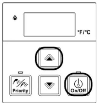
Figure 44

WARNING
Some of the checks below should be performed by a trained and qualified professional. Consumers should never attempt any action that they are not qualified to perform.
10
Air Supply or Exhaust Blockage
- Ensure approved venting materials are being used.
- Check that nothing is blocking the flue inlet or exhaust.
- Check all vent components for proper connections.
- Ensure vent length matches with the vent lengths set in the parameter settings.
- Verify High Altitude setting are set properly.(See Parameter Setting)
- Check fan for blockage.
* See “Electrical Diagnostics” on Technical Data Sheet located on inside front cover of water heater.
11
No Ignition (Heater Not Turning On)
- Check that the gas is turned on at the water heater, meter, or propane cylinder.
- If the system is propane, make sure that gas is in the tank.
- Bleed all air from the gas line
- Ensure appliance is properly grounded.
- Ensure gas type and pressure is correct.
- Ensure gas line, meter, and/or regulator is sized properly.
- Verify parameter setting are set properly.
- Ensure igniter is operational.
- Check igniter wiring harness for damage.
- Check gas solenoid valves for open circuits.
- Ensure flame rod wire is connected.
- Check flame rod for carbon build-up.
- Remove burner cover and ensure burners are properly seated.
- Remove burner plate; inspect burner surface for condensation/debris.
- Check the ground wire for the PC board.
| 12 | No Flame |
| Check that the gas is turned on at the water heater, meter, or cylinder.Check for obstructions in the flue outlet.If the system is propane, make sure that gas is in the tank.Ensure gas line, meter, and/or regulator is sized properly.Ensure gas type and pressure is correct.Bleed all air from gas lines.Ensure proper venting material was installed.Ensure condensation collar was installed properly.Ensure vent length is within limits.Verify parameter setting are set properly.Check power supply for loose connections.Check power supply for proper voltage and voltage drops.Ensure flame rod wire is connected.Check flame rod for carbon build-up.Disconnect and reconnect all wiring harnesses on unit and PC board.Check gas solenoid valves for open circuits.Remove burner plate; inspect burner surface for condensation/debris. |
* See “Electrical Diagnostics” on Technical Data Sheet located on inside front cover of water heater.
| 14 | Thermal Fuse |
| Check for restrictions in air flow around unit and vent terminal.Check gas type of unit and ensure it matches gas type being used.Check for low water flow in a circulating system causing short-cycling.Check for foreign materials in combustion chamber and exhaust piping.Check heat exchanger for cracks or separations.Check heat exchanger surface for hot spots which may be caused by scale build-up. Refer to instructions in manual for flushing heat exchanger. Hard water must be treated to prevent scale build up or damage to the heat exchanger.Measure resistance of safety circuit.Ensure high fire and low fire manifold pressure is correct.Check for improper gas conversion of product. |
| 16 | High Outgoing Temperature |
| Check for restrictions in air flow around unit and vent terminal.Check for low water flow in a circulating system causing short-cycling.Check for foreign materials in combustion chamber and exhaust piping.Check for blockage in the heat exchanger.Check the thermistor sensor and clean sensor of scale build-up. | |
| 19 | Electrical Grounding |
| Check all components for electrical short. | |
| 32 | Outgoing Water Temperature Thermistor |
| Check sensor wiring for damage.Measure the resistance of the sensor.(See Electrical Diagnostics)Clean sensor of scale build-up.Replace sensor if necessary. | |
| 33 | Heat Exchanger Thermistor |
| Check sensor wiring for damage.Measure resistance of sensor. (See Electrical Diagnostics)Replace sensor if necessary. | |
| 34 | Combustion Air Temperature Thermistor Fault |
| Check for restrictions in air flow around unit and vent terminal.Check sensor wiring for damage.Measure resistance of sensor.Ensure fan blade is tight on motor shaft and is in good condition.Replace sensor if necessary. | |
| 41 | Freeze Protection Thermistor |
| Check sensor wiring for damage.Measure resistance of sensor. (See Electrical Diagnostics)Replace sensor if necessary. | |
| 51 | Inlet Water Temperature Thermistor |
| Check sensor wiring for damage.Measure resistance of sensor. (See Electrical Diagnostics)Replace sensor if necessary. | |
| 52 | Modulating Solenoid Valve Signal |
| Check modulating gas solenoid valve wiring harness for loose or damaged terminals.Measure resistance of valve coil. | |
| 61 | Combustion Fan |
| Ensure fan will turn freely.Check wiring harness to motor for damaged and/or loose connections.Measure resistance of motor winding. | |
| 63 | Recirculation Low Flow |
| Ensure the inlet water filter is clean and free of debris.Ensure parameter setting are correctly set for recirculation mode.Ensure pump supply voltage.Check the wiring harness to the pump and PCB for damaged and/or loose connections.Ensure air is removed from the recirculation line. | |
| 65 | Water Flow Servo |
| Measure the resistance values and voltage of the water flow control.*Ensure the harness and connector are not wet.If the voltage from the PC Board is abnormal, replace the PC Board; otherwise, replace the water flow servo valve. |
| 65 | Bypass Flow Servo |
| Measure the resistance values and voltage of the bypass servo valve.*Ensure the harness and connector are not wet.If the voltage from the PC Board is abnormal, replace the PC Board; otherwise, replace the bypass servo valve. | |
| 70 | PC Board |
| Check the connection harness at the connection on the PC board.Replace PC board. | |
| 71 | Solenoid Valve Circuit |
| Ensure dip switch on PC board is in the OFF position.Check gas solenoid valves for short circuits or grounding.Ensure heater circuit is not grounded.Replace PC Board. | |
| 72 | Flame Sensing Device |
| Verify flame rod is touching flame when unit fires.Check the flame rod and wire for damage.Remove flame rod;check for carbon build-up; clean with sand paper.Check inside burner chamber for any foreign material blocking flame at flame rod.Check the resistance to the cabinet.If there is no issue with the flame rod or wiring, replace the PC Board | |
| 79 | Water Leak Detected |
| Turn off water supply and contact licensed professional. |
* See “Electrical Diagnostics” on Technical Data Sheet located on inside front cover of water heater.
| LC | Scale Build-up in Heat Exchanger (when checking maintenance code history, "00" is substituted for "LC") |
| LC indicates that there is scale build up in the heat exchanger and that the heat exchanger needs to be flushed to prevent damage. Refer to the flushing instructions in the manual. Hard water must be treated to prevent scale build up or damage to the heat exchanger.After flushing, reset LC code as instructed.Please call Rinnai technical department. | |
| FF | Maintenance Indicator |
Placeholder in Diagnostic code history indicating that a service provider performed maintenance or service.Enter this code after performing service by pressing ▲ (Up),▼ (Down) and On/Off simultaneously.FF is visible on the monitor.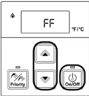 | |
| SS | (SS) Service Soon (Flush Heat Exchanger) |
| SS is a time-based service indicator set during installation. See section "4.10 Configure Parameter Settings" for additional details on setting and changing the SS indicator.SS indicates that it is time for service. The heat exchanger should be flushed to prevent damage (refer to section "6.2 Flushing the Heat Exchanger" for more information).Hard water must be treated to prevent scale build-up or damage to the heat exchanger.To reset the SS code, push the On/Off button on the temperature controller 5 times in 5 seconds. |
| NO CODE - Nothing happens when water flow is activated | |
| Clean inlet water supply filter.On new installations ensure hot and cold water lines are not reversed.Verify you have at least the minimum flow rate required to fire unit.Check for cold to hot cross over. Isolate circulating system if present. Turn off cold water to the unit, open pressure relief valve; if water continues to flow, there is bleed over in your plumbing.Verify turbine spins freely.Measure the resistance of the water flow control sensor.If the display is blank and clicking is coming from the unit, disconnect the water flow servo motor (GY, BR, O, W, P, BL, R). If the display comes on then replace the water flow servo motor. |
* See "Electrical Diagnostics" on Technical Data Sheet located on inside front cover of water heater.
6. Maintenance
Topics in this section
- Maintenance
- Flushing the Heat Exchanger
- Draining the Water Heater
6.1 Maintenance
This water heater must be inspected annually by a trained and qualified professional. Repairs and maintenance shall be performed by a trained and qualified professional. The trained and qualified professional must verify proper operation after servicing.

WARNING
To protect yourself from harm, before performing maintenance:
- Turn off the electrical power supply by unplugging the power cord or by turning off the electricity at the circuit breaker. (The temperature controller does not control the electrical power.)
- Turn off the gas at the manual shutoff (control) valve, usually located immediately below the water heater.
- Turn off the incoming water supply. This can be done at the isolation valve immediately below the water heater or by turning off the water supply to the building.

WARNING
Keep the appliance area clear and free from combustible materials, gasoline, and other flammable vapors and liquids.
The following maintenance items are required for the proper operation of your water heater.
CLEANING
It is imperative that control compartments inside the cabinet, burners, and circulating air passageways of the appliance be kept clean.
BURNER
Check burner flame for proper color. The flame must burn with a clear, blue, stable flame. Once ignited, the flame must cover the surface of the burner. If the flame does not have this appearance, complete the following steps:
- Turn off and disconnect electrical power. Allow to cool.
- Remove the front panel by removing two latch style clips at the top and two screws at the bottom of the water heater.
- Use a vacuum to remove dust and debris from the main burner and fan blades on the burner or distribution plate (bottom). DO NOT use a wet cloth or spray cleaners on the burner. DO NOT use volatile substances such as benzene and thinners; they may ignite or fade the paint.
- Use soft dry cloth to wipe the cabinet.
VENT SYSTEM
Periodic cleaning and inspection of the vent system is needed, and includes the screens in the vent termination.
The vent system should be inspected for blockages including snow or other debris or damage. If the vent is blocked and cannot be easily cleared, contact a trained and qualified professional.
MOTORS
Motors are permanently lubricated and DO NOT need periodic lubrication. However you must keep fan and motor free of dust and dirt by cleaning annually.
Use a soft damp cloth to clean the temperature controller. DO NOT use solvents.
LIME/SCALE BUILD-UP
Scale build-up is caused by hard water and can be accelerated if the water heater is set at a high temperature. Refer to section "6.2 Flushing the Heat Exchanger" for more information. Refer to section "Water Quality Guidelines" to determine if your water needs to be treated or conditioned. The water must be potable, free of corrosive chemicals, sand, dirt, or other contaminates. It is up to the installer to ensure the water does not contain corrosive chemicals, or elements that can affect or damage the heat exchanger. Water that contains chemicals exceeding required levels, affect and damage the heat exchanger. Replacement of the heat exchanger due to water quality damage is not covered by the warranty.
SNOW ACCUMULATION
Keep the area around flue terminal free of snow and ice. The water heater will not function properly if the combustion air or exhaust vent pipes are blocked or partially blocked by obstructions.
Keep the condensate drain line free of snow and ice. Ensure the line is not blocked or clogged and that condensate is flowing freely.
COASTAL INSTALLATIONS
Installations in or near coastal areas may require additional maintenance due to corrosive airborne ocean salt. If corrosion is observed on the body of the water heater, the water heater shall be inspected to ensure proper operation and if necessary, repaired or replaced.
WATER FILTERS
Clean the inlet water filter by closing the cold and hot water inlet isolation (shut-off) valves. Put a bucket under the filter at the bottom of the water heater to catch any water that is contained inside the unit. Unscrew the water filter. Rinse the filter to remove any debris. Install the filter and open the isolation valves.
PRESSURE RELIEF VALVE
Operate the pressure relief valve manually once a year. In doing so, it will be necessary to take precautions with regard to the discharge of potentially scalding hot water under pressure. Ensure discharge has a safe place to flow. Contact with your body or other property may cause damage or harm.

WARNING
Testing the pressure relief valve should only be performed by a trained and qualified professional. Water discharged from the pressure relief valve could cause severe burns instantly or death from scalds.
VISUAL INSPECTION OF FLAME
Verify proper operation after servicing. The burner must flame evenly over the entire surface when operating correctly. The flame must burn with a clear, blue, stable flame. See the parts breakdown of the burner for the location of the view ports.
The flame pattern should be as shown in the images below:

SATISFACTORY
FRONT VIEW
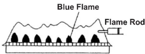
Figure 45

UNSATISFACTORY
FRONT VIEW
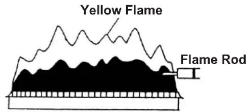
Figure 46
FREEZE PROTECTION
Make sure in case of freezing weather that the water heater and its water lines are adequately protected to prevent freezing. Damage due to freezing is not covered by the warranty. Refer to the "Freeze Protection" section (Section 4.3 Choose an Installation Location > Freeze Protection). The water heater may be drained manually. However, it is highly recommended that drain down solenoid valves be purchased and installed, which will automatically drain the water heater if power is lost. (The Pressure Relief Valve is not affected by the auto drain down solenoid valves and will have to be manually opened.)
WINTERIZATION
The following recommendations are intended to suggest practices that are effective for winterizing the water heater. They should be used as a guide only. No liability is assumed for any issues resulting from the use of this information.
Note: See section "6.3 Draining the Water Heater" for detailed instructions on:
- Draining the water heater
- Running a low volume of water through the water heater to prevent freezing
• Steps to take when the water heater or external pipes have frozen
Gas
Shut off the gas to the water heater. It is generally preferable to shut off the gas service to the entire location if gas is not going to be used.
Water
- Shut off the cold water supply to the water heater. It is generally preferable to shut off the water to the entire location if water is not going to be used.
- Drain the water heater by opening the drain valves on the cold water line and hot water line.
- Open several hot water taps and remove the filter assembly at the water inlet in order to allow room for expansion in case there is water in the lines that freeze.
Electric
Disconnect the power supply by either unplugging the electrical cord or by turning off the circuit breaker to the water heater to prevent potential damage from irregular power surges or interruptions.
6.2 Flushing the Heat Exchanger
This water heater includes a service indicated/reminder (Service Soon, 55). When selected in the parameter settings, an 55 code will display on the controller indicating that it is time to flush and service the water heater. An LC diagnostic code also indicates the unit is beginning to lime up and must be flushed. Failure to flush the appliance will cause damage to the heat exchanger. Damage caused by lime build-up is not covered by the water heater's warranty. Rinnai strongly recommends installation of isolation valves to allow for flushing of the heat exchanger.
- Turn power on at the controller.
- Disconnect electrical power from the source.
- Close the shutoff valves on both the hot water and cold water lines (V3 and V4).
-
Connect pump outlet hose (H1) to the cold water line at isolation valve (V2).
-
Connect drain hose (H3) to the hot water line at isolation valve (V1).
-
Pour four gallons of undiluted virgin, food grade, white vinegar into pail.
-
Place the drain hose (H3) and the hose (H2) to the pump inlet into the cleaning solution.
-
Open both isolation valves (V1 and V2) on the hot water and cold water lines.
-
Restore power to the water heater for 20-30 sec. (this will open the water flow servo).
-
Disconnect electric power from the source.
-
Operate the pump and allow the vinegar to circulate through the water heater for at least 1 hour at a rate of four gallons per minute (15.1 liters per minute).
-
Turn off the pump.
-
Rinse the vinegar from the water heater as follows:
A. Remove the free end of the drain hose (H3) from the pail. Place in sink or outside to drain.
B. Close isolation valve (V2) and open shutoff valve (V4). DO NOT open shutoff valve (V3).
C. Allow water to flow through the water heater for five minutes.
D. Close shutoff valve (V4). When unit has finished draining remove the in-line filter at the cold water inlet and clean out any residue. Place filter back into unit and open valve (V4).
E. Close isolation valve (V1) and open shutoff valve (V3).
-
Disconnect all hoses.
-
Restore electrical power to the water heater.

NOTE
Scale build-up will affect the performance of the water heater. Water should be treated. Rinnai offers water conditioning solutions that provide superior lime scale prevention and corrosion control by feeding a blend of scale control compounds into the cold water supply. Refer to section "3.5 Accessories" for more information.
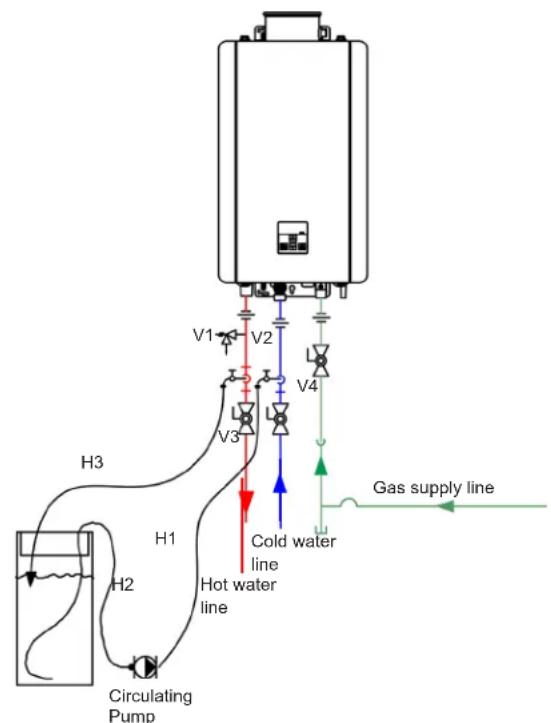
flowchart
graph TD
    A["Circulating Pump"] --> B["Hot water line"]
    B --> C["H1"]
    C --> D["V3"]
    D --> E["V2"]
    E --> F["V1"]
    F --> G["V4"]
    G --> H["Gas supply line"]
    style A fill:#f9f,stroke:#333
    style B fill:#ccf,stroke:#333
    style C fill:#cfc,stroke:#333
    style D fill:#fcc,stroke:#333
    style E fill:#cff,stroke:#333
    style F fill:#ffc,stroke:#333
    style G fill:#fcf,stroke:#333
    style H fill:#cff,stroke:#333
Figure 47
6.3 Draining the Water Heater

WARNING
To avoid burns, wait until the equipment cools down before draining the water. The water in the appliance will remain hot after it is turned off.
If the water heater is not going to be used during a period of possible freezing weather, it is recommended that the water inside the water heater be drained.
To manually drain the water:
- Shut off cold water supply and gas supply.
- Turn off the temperature controller.
- Disconnect the power to the water heater.
- Close the hot and cold isolation valves.
- Open the pressure relief valve (PRV) lever.
- Open the hot and cold drain valves and loosen the inlet water filter.
To resume normal operation:
- Confirm that the gas supply is turned off, all taps are closed and PRV lever is closed.
- Close the hot and cold drain valves.
- Open the cold and hot water isolation valves.
- Connect power to the water heater and tighten the inlet water filter.
- Open a tap and confirm that water flows, and then close.
- After confirming that the temperature controller is off, turn on the gas supply.
- Turn on the temperature controller.
Running a low volume of water through the water heater to prevent freezing:
If the temperature exceeds the ability of the water heater to freeze protect itself, or if power is lost, the following steps may prevent the water heater and external piping from freezing. Units connected with EZConnect™ (2-unit link) should be drained to prevent freezing if not in use.
- Turn the water heater off and close the gas supply valve.
- Turn on a hot water tap to flow water about 0.1 gal/min (0.4 L/min) or where the stream is about 0.2 in. (5 mm) thick.
When the water heater or external piping has frozen:
- DO NOT operate the water heater if the unit or the external piping is frozen.
- Close the gas and water valves and turn off the power.
- Wait until the water thaws. Check by opening the water supply valve.
- Check the water heater and the piping for leaks.
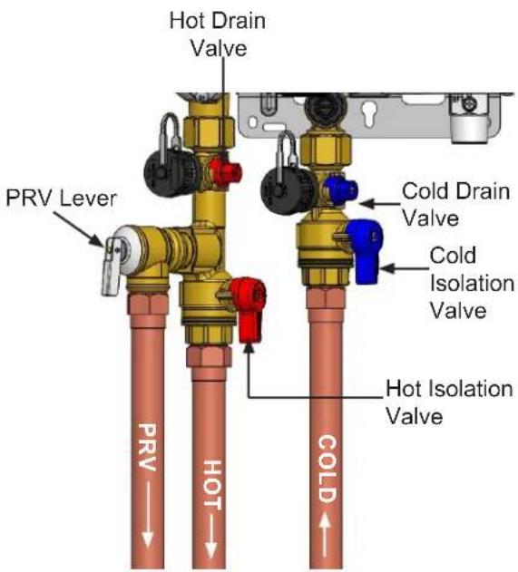
Figure 48: Piping Diagram
7. Appendices
Topics in this section
• Massachusetts State Gas Regulations
- Wiring Diagram
- Ladder Diagram
• Pressure Drop and Water Flow Curves
• Guidelines for Additional Temperature Controllers
7.1 Massachusetts State Gas Regulations
For Gas Models Sold in Massachusetts
NOTICE BEFORE INSTALLATION:
This direct-vent appliance must be installed by a properly trained licensed professional. If you are not properly trained, you must not install this unit.
IMPORTANT: In the State of Massachusetts (248 CMR 4.00 & 5.00):
For all side wall horizontally vented gas fueled equipment installed in every dwelling, building or structure used in whole or in part for residential purposes, including those owned or operated by the Commonwealth and where the side wall exhaust vent termination is less than 7 ft above finished grade in the area of the venting, including but not limited to decks and porches, the following requirements shall be satisfied:
- INSTALLATION OF CARBON MONOXIDE DETECTORS. At the time of installation of the side wall horizontal vented gas fueled equipment, the installing plumber or gas fitter shall observe that a hard-wired carbon monoxide detector with an alarm and battery back-up is installed on the floor level where the gas equipment is to be installed. In addition, the installing plumber or gas fitter shall observe that a battery operated or hard wired carbon monoxide detector with an
alarm is installed on each additional level of the dwelling, building or structure served by the side wall horizontal vented gas fueled equipment. It shall be the responsibility of the property owner to secure the services of a trained and qualified professional for the installation of hard-wired carbon monoxide detectors.
F. In the event that the side wall, horizontally vented gas fueled equipment is installed in a crawl space or an attic, the hard-wired carbon monoxide detector with alarm and battery back-up may be installed on the next adjacent floor level.
G. In the event that the requirements of this subdivision cannot be met at the time of completion of installation, the owner shall have a period of thirty (30) days to comply with the above requirements; provided, however, that during said thirty (30) day period, a battery operated carbon monoxide detector with an alarm shall be installed.
-
APPROVED CARBON MONOXIDE DETECTORS. Each carbon monoxide detector as required in accordance with the above provisions shall comply with NFPA 720 and be ANSI/UL 2034 listed and IAS certified.
-
SIGNAGE. A metal or plastic identification plate shall be permanently mounted to the exterior of the building at a minimum height of 8 ft above grade directly in line with the exhaust vent terminal for the horizontally vented gas fueled heating appliance or equipment. The sign shall read, in print size no less than one-half (1/2) inch in size, "GAS VENT DIRECTLY BELOW. KEEP CLEAR OF ALL OBSTRUCTIONS."
-
INSPECTION. The state or local gas inspector of the side wall horizontally vented gas fueled equipment shall not approve the installation unless, upon inspection, the inspector observes carbon monoxide detectors and signage installed in accordance with the provisions of 248 CMR 5.08(2)(a)1 through 4.
COMBINATION SPACE HEATING/POTABLE WATER SYSTEM
(For Use In Commonwealth of Massachusetts)
Use Only in Commonwealth of Massachusetts
Figure 49
Water Heater
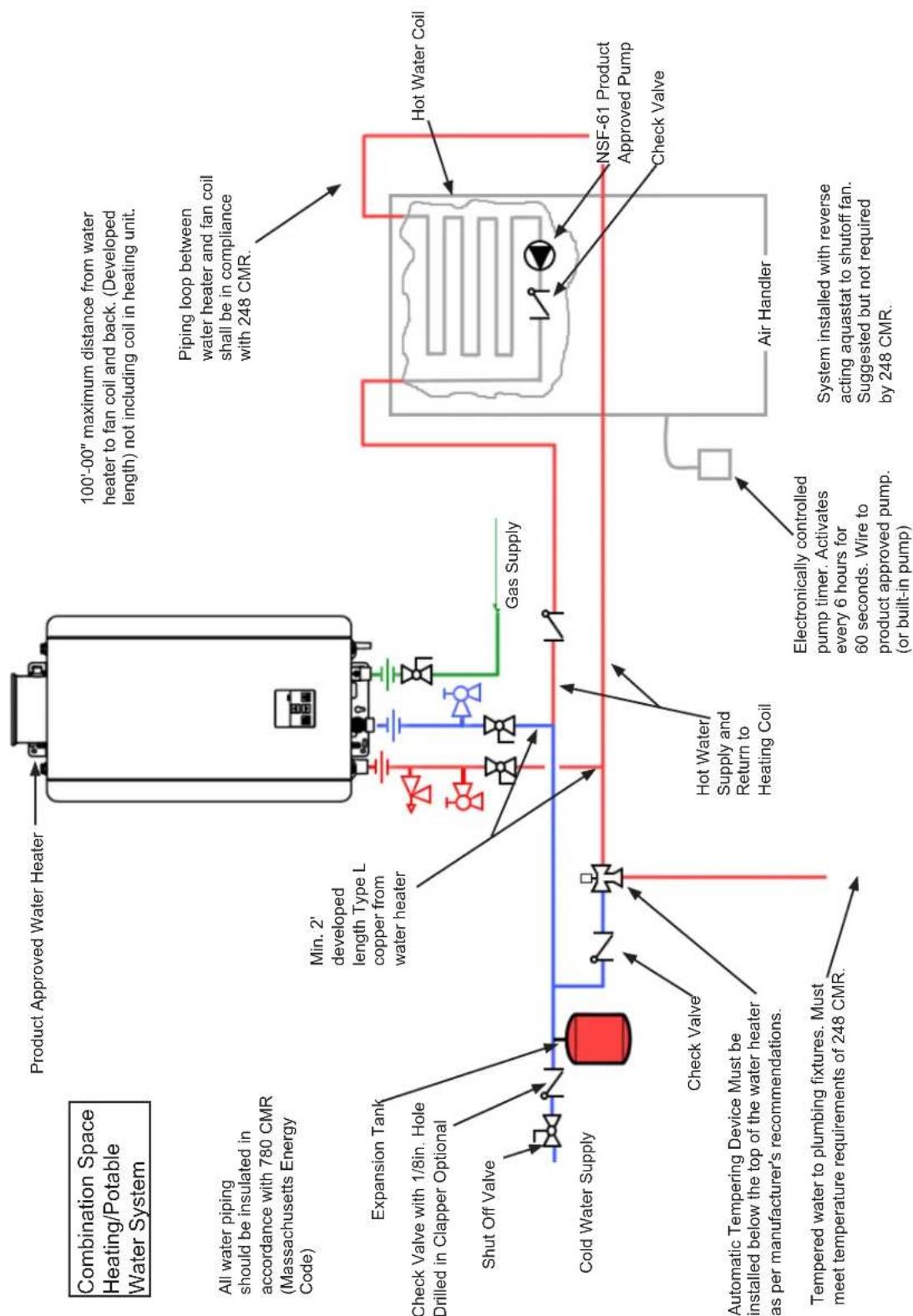
flowchart
graph TD
    A["Combination Space Heating/Potable Water System"] --> B["Product Approved Water Heater"]
    B --> C["Maximulus"]
    C --> D["Min. 2' developed length Type L copper from water heater"]
    D --> E["Gas Supply"]
    E --> F["Hot Water Coil"]
    F --> G["NSF-61 Product Approved Pump Check Valve"]
    G --> H["Air Handler"]
    H --> I["System installed with reverse acting aquastat to shutoff fan. Suggested but not required by 248 CMR."]
    B --> J["Expansion Tank"]
    J --> K["Check Valve with 1/8in. Hole Drilled in Clapper Optional"]
    K --> L["Cold Water Supply"]
    L --> M["Check Valve"]
    M --> N["Tempered water to plumbing fixtures. Must meet temperature requirements of 248 CMR."]
    N --> O["Automatic Tempering Device Must be installed below the top of the water heater as per manufacturer's recommendations."]
    O --> P["Shut Off Valve"]
    P --> Q["All water piping should be insulated in accordance with 780 CMR (Massachusetts Energy Code)."]
72 Wiring Diagram
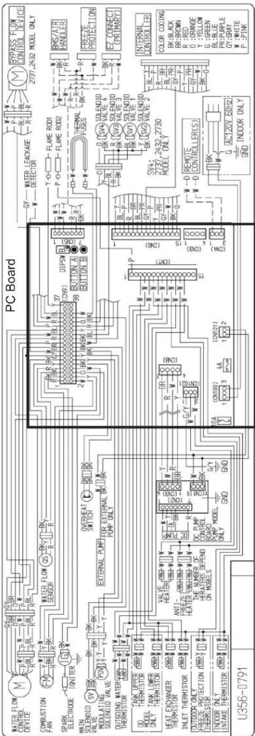
Figure 50
7.3 Ladder Diagram
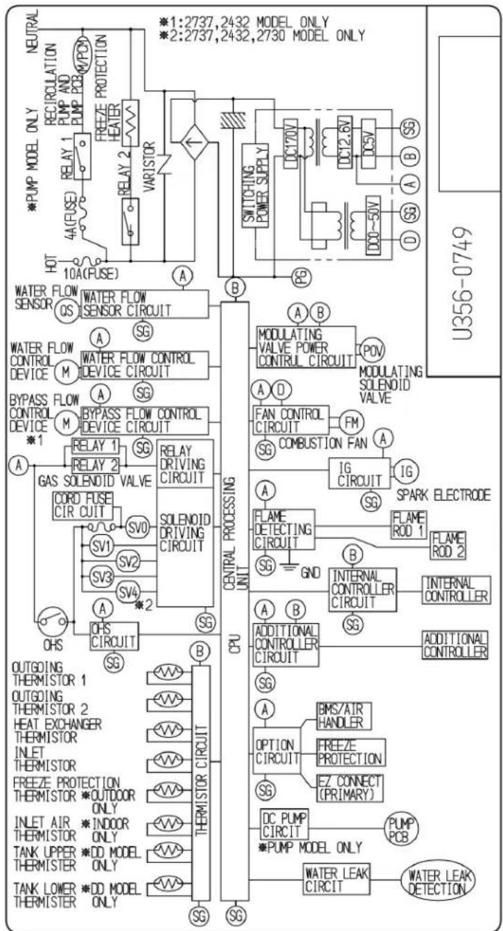
flowchart
graph TD
    A["NEUTRAL"] --> B["RECIRCULATION"]
    B --> C["PUMP AND PUMP PCB"]
    C --> D["RELAY 1"]
    D --> E["RELAY 2"]
    E --> F["HEATER"]
    F --> G["REFZE PROTECTION"]
    G --> H["VARISTOR"]
    H --> I["Switching POWER SUPPLY"]
    I --> J["DC170V"]
    J --> K["DC12.6V"]
    K --> L["DC5V"]
    L --> M["SG"]
    M --> N["A"]
    N --> O["DD~50V"]
    O --> P["S"]
    P --> Q["D"]
    Q --> R["SG"]
    R --> S["SB"]
    S --> T["SWITCHING POWER SUPPLY"]
    T --> U["DC170V"]
    U --> V["DC12.6V"]
    V --> W["DC5V"]
    W --> X["SG"]
    X --> Y["A"]
    Y --> Z["DD~50V"]
    Z --> AA["S"]
    AA --> AB["D"]
    AB --> AC["SG"]
    AC --> AD["SB"]
    AD --> AE["SWITCHING POWER SUPPLY"]
    AE --> AF["DC170V"]
    AF --> AG["DC12.6V"]
    AG --> AH["DC5V"]
    AH --> AI["S"]
    AI --> AJ["A"]
    AJ --> AK["DD~50V"]
    AK --> AL["S"]
    AL --> AM["D"]
    AM --> AN["S"]
    AN --> AO["SG"]
    AO --> AP["SWITCHING POWER SUPPLY"]
    AP --> AQ["DC170V"]
    AQ --> AR["DC12.6V"]
    AR --> AS["DC5V"]
    AS --> AT["S"]
    AT --> AU["A"]
    AU --> AV["DD~50V"]
    AV --> AW["S"]
    AW --> AX["S"]
    AX --> AY["D"]
    AY --> AZ["SG"]
    AZ --> BA["SWITCHING POWER SUPPLY"]
    BA --> BB["DC170V"]
    BB --> BC["DC12.6V"]
    BC --> BD["DC5V"]
    BD --> BE["S"]
    BE --> BF["A"]
    BF --> BG["DD~50V"]
    BG --> BH["S"]
    BH --> BI["D"]
    BI --> BJ["S"]
    BJ --> BK["SG"]
    BK --> BL["SWITCHING POWER SUPPLY"]
    BL --> BM["DC170V"]
    BM --> BN["DC12.6V"]
    BN --> BO["DC5V"]
    BO --> BP["S"]
    BP --> BQ["A"]
    BQ --> BR["DD~50V"]
    BR --> BS["S"]
    BS --> BT["S"]
    BT --> BU["D"]
    BU --> BV["S"]
    BV --> BW["S"]
    BW --> BX["S"]
    BX --> BY["S"]
    BY --> BZ["S"]
    BZ --> CA["S"]
    CA --> CB["S"]
    CB --> CC["S"]
    CC --> CD["S"]
    CD --> CE["S"]
    CE --> CF["S"]
    CF --> CG["S"]
    CG --> CH["S"]
    CH --> CI["S"]
    CI --> CJ["S"]
    CJ --> CK["S"]
    CK --> CL["S"]
    CL --> CM["S"]
    CM --> CN["S"]
    CN --> CO["S"]
    CO --> CP["S"]
    CP --> CQ["S"]
    CQ --> CR["S"]
    CR --> CS["S"]
Figure 51
7.4 Pressure Drop and Water Flow Curves
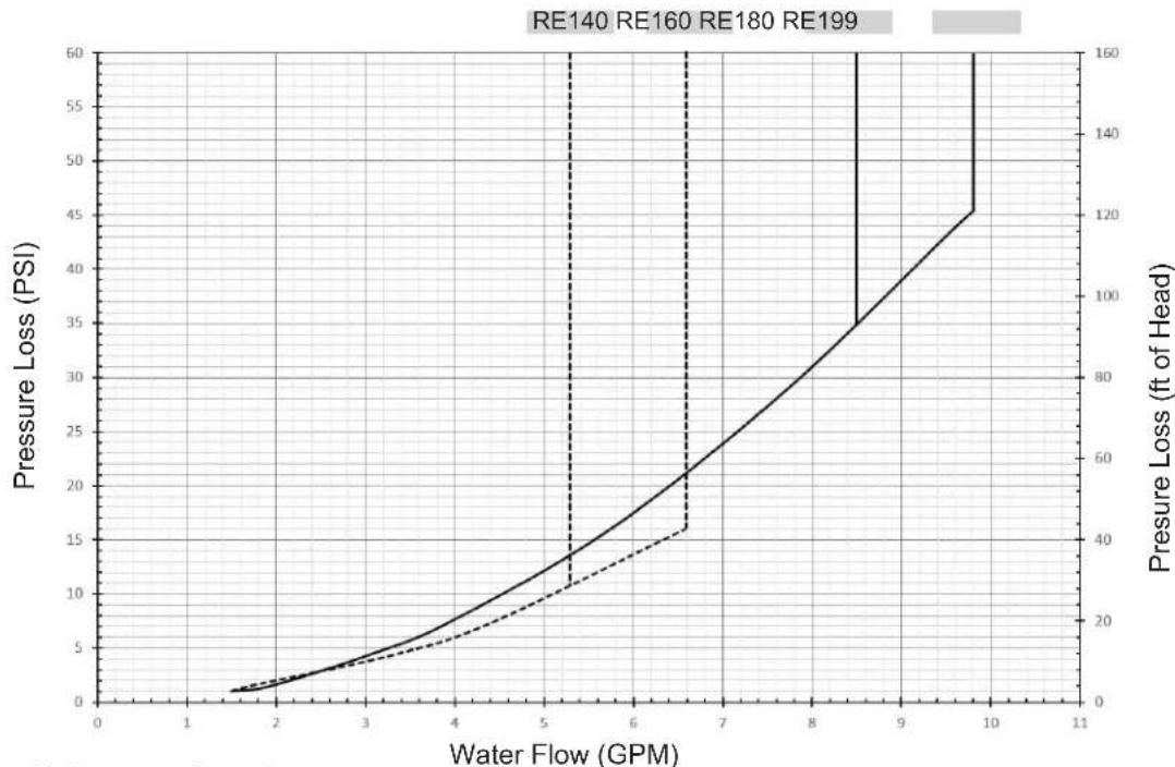
line
| Water Flow (GPM) | Pressure Loss (PSI) | Pressure Loss (ft of Head) | | ---------------- | ------------------- | -------------------------- | | 1 | 0 | 0 | | 2 | 2 | 5 | | 3 | 4 | 15 | | 4 | 7 | 25 | | 5 | 11 | 35 | | 6 | 16 | 45 | | 7 | 22 | 60 | | 8 | 30 | 80 | | 9 | 40 | 100 | | 10 | 50 | 120 | | 11 | 60 | 160 |Figure 52: Pressure Drop Curve
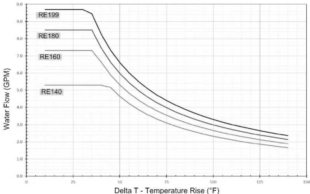
line
| Delta T - Temperature Rise (°F) | RE140 | RE160 | RE180 | RE199 | | -------------------------------- | ----- | ----- | ----- | ----- | | 0 | 5.3 | 7.3 | 8.5 | 9.7 | | 25 | 5.3 | 7.3 | 8.5 | 9.7 | | 50 | 5.3 | 7.3 | 8.5 | 9.7 | | 75 | 4.0 | 5.5 | 6.5 | 7.5 | | 100 | 3.0 | 4.5 | 5.5 | 6.5 | | 125 | 2.5 | 3.5 | 4.5 | 5.5 | | 150 | 2.0 | 3.0 | 4.0 | 5.0 |Figure 53: Water Flow Curve
7.5 Guidelines for Additional Temperature Controllers
All Rinnai Tankless Water Heaters are equipped with an integrated digital temperature controller that allows for a precise water temperature set-point. Additional digital temperature controllers are available as accessories and must be purchased separately (detailed installation steps included with purchase).
Wiring
A maximum of four temperature controllers can be installed for a water heater or bank of water heaters; this includes the controller built into a Rinnai Tankless Water Heater. Controllers can only be wired in parallel; they cannot be wired in series.
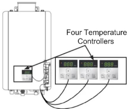
Figure 54
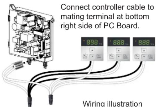
Figure 55
(Detailed wiring instructions included with temperature controller package)
Cable Lengths and Sizes
The temperature controller cable should be a non-polarized two-core cable with a minimum gauge of 22 AWG. The maximum cable length from each temperature controller to the water heater depends on the total number of wired controllers connected to the water heater. Table 24
| Number of Wired Controllers | Maximum Cable Length for Each Controller to Water Heater |
| 1 328 ft (100 m) | |
| 2 164 ft (50 m) | |
| 3 or 4 * 65 ft (20 m) |
* Only three additional controllers can be wired to the water heater.
Location
- The temperature controller should be out of reach of small children.
- Avoid locations where the temperature controller may become hot (near an oven or radiant heater).
- Avoid locations in direct sunlight. The digital display may be difficult to read in direct sunlight.
- Avoid locations where the temperature controller could be splashed with liquids.
- DO NOT install in locations where the temperature controller can be adjusted by the public.
8.8. Warranty Warranty
What is Covered?
The Rinnai Standard Limited Warranty covers any defects in materials or workmanship when the product is installed and operated according to Rinnai written installation instructions, subject to the terms within this Limited Warranty document. This Limited Warranty applies only to products that are installed correctly in the United States. Improper installation may void this Limited Warranty. It is recommended that a trained and qualified professional who has attended a Rinnai installation training class complete your installation. This Limited Warranty coverage, as set out in the table below, extends to the original purchaser and subsequent owners, but only while the product remains at the site of the original installation, and terminates if the product is moved or reinstalled at a new location.
| Item | Period of Coverage (From Date of Purchase) | |
| Residential Applications Commercial Applications | ||
| Heat Exchanger 15 Years | [1] | 8 Years[2] |
| All Other Parts and Components 5 Years | 5 Years | |
| Reasonable Labor 1 Year 1 Year | ||
[1] For residential applications, the heat exchanger warranty is 15 years or 12,000 combustion hours, whichever occurs first.
[2] For commercial applications, the heat exchanger warranty is 8 years or 12,000 combustion hours, whichever occurs first. Notes:
From date of purchase, period of coverage is reduced to 8 years or 12,000 combustion hours, whichever occurs first, if the Rinnai Tankless Water Heater temperature settings exceed 160^ F ( 71^ C).
The integrated controller has a 1 year warranty on parts.
What Will Rinnai Do?
Rinnai will repair or replace the covered product or any part or component that is defective in materials or workmanship as set forth in the above table. Rinnai will pay reasonable labor charges associated with the repair or replacement of any such part or component during the term of the labor warranty period. All repair parts must be genuine Rinnai parts. All repairs or replacements must be performed by a qualified professional who is properly trained to do the type of repair.
Replacement of the product may only be authorized by Rinnai at its sole discretion. Rinnai does not authorize any person or company to assume for it any obligation or liability in connection with the replacement of the product. If Rinnai determines that repair of a product is not possible, Rinnai may replace the product with a comparable product at Rinnai's sole discretion. The warranty claim for product parts and labor may be denied if a component or product returned to Rinnai is found to be free of defects in material or workmanship; damaged by improper installation, use or operation; or damaged during return shipping.
How To Obtain Service
For the name of a trained and qualified professional, please contact your place of purchase, visit the Rinnai website (www.rinnai.us), call Rinnai at 1-800-621-9419 or write to Rinnai at 103 International Drive, Peachtree City, Georgia 30269.
Proof of purchase is required to obtain warranty service. You may show proof of purchase with a dated sales receipt, or by registering within 30 days of purchasing the product. To register your Rinnai Tankless Water Heater, please visit www.rinnai.us. For those without internet access, please call 1-800-621-9419. Receipt of registration by Rinnai will constitute proof-of-purchase for this product. Registration of product installed in new home construction may be verified with a copy of the closing papers provided by the initial home buyer. However, registration is not necessary in order to validate this Limited Warranty.
What Is Not Covered?
This Limited Warranty does not cover any failures or operating difficulties due to the following:
- Accident, abuse, or misuse
- Alteration of the product or any component part
• Misapplication of this product - Improper installation (such as but not limited to)
- Product being installed in a corrosive environment
- Condensate damage
- Improper venting
- Incorrect gas type
- Incorrect gas or water pressure
• Absence of a drain pan under the appliance - Improper maintenance (such as but not limited to scale build-up, freeze damage, or vent blockage)
- Incorrect sizing
- Any other cause not due to defects in materials or workmanship
- Problems or damage due to fires, flooding, electrical surges, freezing or any acts of God
- Any damage caused by poor water quality
- Operating the water heater with anything other than potable water at all times
- Force majeure
There is no warranty coverage on product installed in a closed loop application, commonly associated with space heating only applications.
Use of an MCC-601 controller in a residential dwelling will reduce the warranty coverage to that of a commercial warranty application except when an MCC-601 is used with a hydronic air handler for temperatures no higher than 160^ F ( 71^ C).
This Limited Warranty does not apply to any product whose serial number or manufacture date has been defaced.
This Limited Warranty does not cover any product used in an application that uses chemically treated water such as a pool or spa heater.
Limitation on Warranties
No one is authorized to make any other warranties on behalf of Rinnai America Corporation. Except as expressly provided herein, there are no other warranties, expressed or implied, including, but not limited to warranties of merchantability or fitness for a particular purpose, which extend beyond the description of the warranty herein.
Any implied warranties of merchantability and fitness arising under state law are limited in duration to the period of coverage provided by this Limited Warranty, unless the period provided by state law is less. Some states do not allow limitations on how long an implied Limited Warranty lasts, so the above limitation may not apply to you.
Rinnai shall not be liable for indirect, incidental, special, consequential or other similar damages that may arise, including lost profits, damage to person or property, loss of use, inconvenience, or liability arising from improper installation, service or use. Some states do not allow the exclusion or limitation of incidental or consequential damages, so the above limitation may not apply to you.
This Limited Warranty gives you specific legal rights, and you may also have other rights which vary from state to state.
www.rinnai.us/warranty
Rinnai America Corporation
103 International Drive
Peachtree City, GA 30269
Tel: 1-800-621-9419
Web: rinnai.us
rinnai.ca
100000722(02)
12/2021


- Tankless Water Heater
- Installation and Operation Manual
- WARNING
- Full-length Spanish version available online at rinnai.us
- Contents
- Maintenance 53
- Appendices 58
- Warranty 64
- Welcome
- To The Installer
- To The Consumer
- Acronyms and Abbreviations
- SafetySafety
- Safety Symbols
- DANGER
- CAUTION
- Safety Precautions
- About the Water Heater
- Topics in this section
- Front and Bottom View
- Main Components
- Specifications
- Dimensions
- Supply Connections
- Indoor Models
- Outdoor Models
- Accessories
- Install the Water Heater
- THIS SECTION IS INTENDED FOR THE INSTALLER
- Installation Guidelines
- DO NOT
- What You Will Need
- Items Included
- Items Needed (Field-Supplied)
- Choose an Installation Location
- Water Quality Guidelines
- Environment
- Indoor Water Heaters
- Outdoor Water Heaters and Vent Terminations
- Freeze Protection
- Clearances
- Installation Location Checklist
- Mount the Water Heater to the Wall
- Instructions for Indoor Models
- You Will Need:
- Supplied by Installer:
- Instructions:
- Instructions for Outdoor Models
- Vent the Water Heater
- Guidelines
- IMPORTANT
- Termination Considerations
- Direct Vent (Indoor): Concentric Pipe
- Approved Vent Manufacturers and Products
- Direct Vent (Indoor): Termination Clearances
- Maximum Vent Length
- Venting Installation
- Condensate
- Must Do
- Information
- Other than Direct Vent (Outdoor): Termination Clearances
- Termination Clearances for External (Outdoor) Water Heaters
- Adjustment for High Altitude Installations
- Connect Water Supply
- Guidelines
- Instructions
- PIPING DIAGRAM FOR BASIC INSTALLATION
- KEY
- Install Pressure Relief Valve
- Guidelines
- Pressure Relief Valve Maintenance:
- Connect the Gas Supply
- Instructions
- Gas Pipe Sizing Reference Tables
- Natural Gas
- Propane (Undiluted)
- Connect the Power Supply
- Guidelines
- Configure Parameter Settings
- Instructions
- Service Indicator (Service Soon, 55)
- Recirculation
- Pump Size
- Installation
- Post-Water Heater Installation Checklist
- OperationOperation
- Safety Precautions
- Operating Instructions
- OPERATING INSTRUCTIONS
- TURN OFF GAS TO APPLIANCE
- Control Panel
- Setting the Controller to Mute
- Locking the Controller
- Setting the Temperature
- Available Temperatures with an Internal Controller
- Alternate Temperatures Settings
- Performance Data
- To obtain performance data:
- Diagnostic Codes
- To display diagnostic codes:
- 10
- Air Supply or Exhaust Blockage
- 11
- No Ignition (Heater Not Turning On)
- Maintenance
- Maintenance
- CLEANING
- BURNER
- VENT SYSTEM
- MOTORS
- LIME/SCALE BUILD-UP
- SNOW ACCUMULATION
- COASTAL INSTALLATIONS
- WATER FILTERS
- PRESSURE RELIEF VALVE
- VISUAL INSPECTION OF FLAME
- FREEZE PROTECTION
- WINTERIZATION
- Gas
- Water
- Electric
- Flushing the Heat Exchanger
- NOTE
- Draining the Water Heater
- To manually drain the water:
- To resume normal operation:
- When the water heater or external piping has frozen:
- Appendices
- Massachusetts State Gas Regulations
- NOTICE BEFORE INSTALLATION:
- COMBINATION SPACE HEATING/POTABLE WATER SYSTEM
- (For Use In Commonwealth of Massachusetts)
- Wiring Diagram
- Ladder Diagram
- Pressure Drop and Water Flow Curves
- Guidelines for Additional Temperature Controllers
- Wiring
- Cable Lengths and Sizes
- Location
- Warranty Warranty
- What is Covered?
- What Will Rinnai Do?
- How To Obtain Service
- What Is Not Covered?
- Limitation on Warranties
- Rinnai America Corporation
Brand : Rinnai
Model : RE140eP
Category : Instant water heater and boiler