
Secutor Pro TS50-384 - Thermal camera AGM - Free user manual and instructions
Find the device manual for free Secutor Pro TS50-384 AGM in PDF.


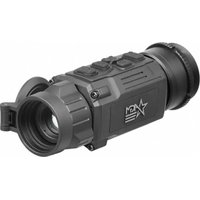
| Product Type | Thermal Imaging Weapon Sight |
| Model | Secutor Pro TS50-384 |
| Magnification | 2.4x |
| Objective Lens | 50 mm F/1.0 Germanium |
| Detector Type | 17 μm Uncooled Microbolometer |
| Detector Resolution | 384 x 288 |
| Frame Rate | 50 Hz |
| Display Resolution | HD 1024 x 768 |
| Digital Zoom | 1x, 2x, 4x, PIP (Picture-in-Picture) |
| Image Palettes | White Hot, Black Hot, and multiple color palettes |
| Reticle Patterns | 5 patterns; Colors: Black, White, Red, Cyan |
| Boresight Adjustment | Digitally controlled |
| Windage Adjustment Increment | 0.8 MOA |
| Elevation Adjustment Increment | 0.4 MOA |
| Field of View | 7.5° x 5.6° |
| Eye Relief | 40 mm |
| Focusing Range | 10 m to infinity |
| Diopter Adjustment | Manual; ±5 diopters |
| Battery Type | Two CR123A 3V Lithium batteries |
| Battery Life (at 20°C / 68°F) | Up to 5 hours |
| External Power Options | 5V power bank via Micro-USB; 6V/600mA via S620 connector; Extended Battery Pack (up to 8 additional hours) |
| Weapon Mount Compatibility | Picatinny MIL-STD-1913 and Weaver rails |
| Overall Dimensions | 250 x 70 x 85 mm (9.8 x 2.8 x 3.3 in) |
| Weight (without batteries) | 0.7 kg (1.54 lb) |
| Operating Temperature | -40°C to +50°C (-40°F to +122°F) |
| Storage Temperature | -50°C to +70°C (-58°F to +158°F) |
| Recoil Resistance | 700g |
| Environmental Rating | IP67 (waterproof) |
| Warranty | Limited 3-year warranty |
Frequently Asked Questions - Secutor Pro TS50-384 AGM
User questions about Secutor Pro TS50-384 AGM
0 question about this device. Answer the ones you know or ask your own.
Ask a new question about this device
Download the instructions for your Thermal camera in PDF format for free! Find your manual Secutor Pro TS50-384 - AGM and take your electronic device back in hand. On this page are published all the documents necessary for the use of your device. Secutor Pro TS50-384 by AGM.
USER MANUAL Secutor Pro TS50-384 AGM
SECUTOR
THERMAL IMAGING WEAPON SIGHT
© 2021 AGM Global Vision, LLC. All rights reserved.
This documentation is subject to change without notice.
No parts of this manual, in whole or in part, may be copied, photocopied, translated, or transmitted by any electronic medium or in machine-readable form without the prior written permission of AGM Global Vision, LLC.
Approved for public release, distribution unlimited.
If you have questions that are not covered in this manual, or need service, contact AGM Global Vision customer support for additional information prior to returning a product.
AGM Global Vision, LLC
173 West Main Street
PO Box 962
Springerville, AZ 85938
Tel. 928.333.4300
support@agmglobalvision.com
www.agmglobalvision.com
EXPORT INFORMATION
Buyer acknowledges that all products supplied by AGM Global Vision, LLC are subject to U.S. export control laws, including, but not limited to, the Export Administration Regulations, the International Economic Emergency Powers Act, and various U.S. embargoes and sanctions. AGM Global Vision products may not be exported, re-exported, or transferred contrary to U.S. export control laws. In particular, AGM Global Vision products may not be exported, re-exported, or transferred to prohibited countries, individuals, organizations, or entities, including but not limited to those individuals and entities listed on the List of Specially Designated Nationals and Blocked Persons administered or maintained by the U.S. Office of Foreign Assets Control ("OFAC"), the various lists maintained by the Bureau of Industry and Security of the Department of Commerce, and the U.S. State Department and Buyer represents and warrants that neither Buyer nor any of its officers, directors, or employees are on such lists. Distribution or resale by Buyer to such countries, individuals, organizations, or entities is expressly prohibited. Buyer has and will maintain a positive process to ensure compliance with this Section.
LIST OF CONTENTS
TITLE
PAGE
Safety Summary 4
1. GENERAL INFORMATION 6
1.1 System Description 6
1.2 Standard Components 8
1.3 Optional Equipment 9
1.4 Key Features 10
2. OPERATING INSTRUCTIONS 11
2.1 Installation and Mounting 11
2.2 Controls and Display Indicators 15
2.3 Operating Procedures 24
3. MAINTENANCE INSTRUCTIONS 27
3.1 Troubleshooting 27
3.2 Maintenance 28
4. WARRANTY INFORMATION 29
4.1 Warranty Information and Registration 29
5. SPECIFICATIONS 31
5.1 Specifications 31
APPENDIX 33
A. Spare Parts List 33
SAFETY SUMMARY
- Read and follow all instructions
- Read all warnings
- Only use the attachments/accessories specified by the manufacturer
- All service must be provided by the manufacturer
WARNING:
This product contains natural rubber latex, which may cause allergic reactions! The FDA has reported an increase in the number of deaths associated with sensitivity to natural latex proteins. If you are allergic to latex, learn which products contain it and strictly avoid exposure to those products.
WARNING:
Always make sure your firearm is unloaded before you place the scope on the firearm. Reconfirm that the chamber is empty if you stop the procedure then resume later. Safe handling rules should be followed at all times.
WARNING:
If a scope is mounted too far to the rear, the eyepiece can injure the shooter's brow. Shooting at an uphill angle also increases this hazard because it shortens the distance between the brow and the rear of the scope. For this reason, AGM scopes are engineered to provide generous eye relief. Therefore, when mounting your scope, we recommend positioning it as far forward in the mounts as possible to take full advantage of this generous eye relief. With hard-recoiling rifles, serious injury or even death can result from eyepiece impact with the shooter during the recoil process when discharging the firearm. Be certain that your installation provides sufficient eye relief for the recoil generated by your rifle before shooting the firearm.
NOTE: Give special attention to this warning when shooting uphill and/or from a prone position. These shooting conditions can dramatically reduce eye relief. PLEASE maintain maximum eye relief when shooting heavy recoiling and/or magnum firearms. THE USER ASSUMES ALL RESPONSIBILITY AND LIABILITY FOR HAVING THE AGM RIFLESCOPE PROPERLY MOUNTED TO A FIREARM AND USING THE AGM RIFLESCOPE PROPERLY. ALWAYS CHECK THE CONDITION OF YOUR MOUNTING SYSTEM PRIOR TO USING YOUR FIREARM.
CAUTION:
- Do not dismantle the equipment.
- Keep the equipment clean. Protect it from moisture, dramatic temperature drops, and electrical shocks.
- DO NOT force the equipment controls past their stopping points.
- DO NOT leave the equipment activated during breaks in operation.
- DO NOT store the equipment with the batteries installed.
- Thoroughly clean and dry each item before placing them into the storage case.
CAUTION:
To prevent thermal damage to the equipment, never point it, either on or off, directly at the sun or any other source of high intensity light that the unprotected human eye cannot tolerate (such as a welding arc). To prevent inadvertent exposure to these types of sources, never leave the equipment with the objective lens cap off.
NOTES:
• Secutor must be zeroed each time it is mounted to a new weapon.
- To avoid losing unsaved data, DO NOT remove the batteries or disconnect the external power source while the Secutor is on.
- Inadvertent sun damage is not considered a defect in material or workmanship, and is therefore not covered in the product warranty.
1 GENERAL INFORMATION
1.1 SYSTEM DESCRIPTION
The Secutor is a thermosensitive device equipped with an aiming reticle. The Secutor senses the differences in heat emitted by objects in its field of view and converts the received temperature pattern into a viewable image that represents the scene in contrasting black and white or color patterns, depending on the user's selected image palette.
NOTE:
It is important that the Secutor sensor receive sufficient thermal contrast between the target and background area, or between the different parts of a target. For example, there would be a vast temperature contrast between the snow and any heat target (such as an animal), making it exceptionally easy to distinguish the target.
The Secutor consists of two primary parts: a thermal imaging aiming device and a mount. The equipment comes as shown in Figure 1-1, with the mount secured to the body of the device. The figure represents three versions of the device equipped with objective lenses with 25mm, 50mm, and 75mm focal length.

FIGURE 1-1. SECUTOR SERIES THERMAL IMAGING WEAPON SIGHTS
All Secutor series scopes are based on 17um uncooled cameras that allow for improvements in overall image quality in a wide range of dynamic thermal environments.
To accommodate individual user needs, the Secutor has a variety of digitally controlled options such as:
• Display brightness, contrast, and sharpness
- Digital zoom
• Reticle type and color selection
- Palette selection (color scheme)
- Boresight adjustments
- Custom profile settings
Information on the current operating state (battery status, active profile, palette setting, the reticle running coordinate in the display etc.) is continuously displayed, making field operation of the Secutor simple and convenient.
Manufactured for exceptional durability, the Secutor has a lightweight and robust aluminum body.
The riflescope is equipped with manual eyepiece and objective lens focusing.
Two side Picatinny/Weaver rails allow for the installation of an optional HD Video Recorder, WiFi Attachment, Extended Battery Pack, or other equipment.
An universal input/output connector enables an external video display (monitor, TV) or video recorder to be connected to the Secutor.
The Secutor is powered by two CR123A (2×3V) batteries that gives up to 5 hours of continues work. An external 6VDC/600mA power source can be connected to the Secutor. An external 5V power bank (battery pack) also can be easily connected via an micro-USB connector for a significant increase of operating time.
The quick-release mount of the Secutor fits any Picatinny, MIL-STD-1913, or Weaver weapon rail. The mount's lever-cam clamping device ensures quick, easy and reliable mounting and removal.
The Secutor with 50mm lens is shown in Figure 1-2. The ITEM column of Table 1-1 indicates the number used to identify items in Figure 1-2.
NOTE:
Here and below, the model Secutor with 50mm Lens is used for the example.
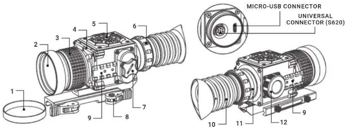
FIGURE 1-2. SECUTOR MAIN PARTS
TABLE 1-1. SECUTOR MAIN PARTS
| ITEM DESCRIPTION ITEM DESCRIPTION | |||
| 1 Objective Lens Cap 7 Battery Cap | |||
| 2 Objective Lens 8 Mount | |||
| 3 Objective Focus Ring 9 Side Picatinny/Weaver | Rail | ||
| 4 Body 10 Eyecup | |||
| 5 | Button Control Panel | 11 | Eyepiece Assembly |
| 6 | Eyepiece Focus Ring | 12 | Connectors Cap |
1.2 STANDARD COMPONENTS
The Secutor standard components are shown in Figure 1-3 and listed in Table 1-2. The ITEM column indicates the number used to identify items in Figure 1-3.

FIGURE 1-3. STANDARD COMPONENTS
TABLE 1-2. STANDARD COMPONENTS
| ITEM DESCRIPTION QUANTITY | |
| 1 Secutor Thermal Imaging Weapon Sight 1 | |
| 2 Objective Lens Cap 1 | |
| 3 Eyecup 1 | |
| 4 CR123A Lithium Battery 2 | |
| 5 Remote Control 1 | |
| 6 Video Cable 1 | |
| 7 Operation Manual 1 | |
| 8 Carrying Case 1 | |
1.3 OPTIONAL EQUIPMENT
Optional items are shown in Figure 1-4 and listed in Table 1-3.
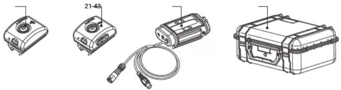
FIGURE 1-4. OPTIONAL EQUIPMENT
The ITEM column indicates the number used to identify items in Figure 1-4.
The PART NO. column indicates the primary number used by the manufacturer, to identify an item.
TABLE 1-3. OPTIONAL EQUIPMENT
| ITEM DESCRIPTION PART NO. | |
| 1 AGM WiFi Attachment 6305WIF1 | |
| 2 AGM HD Recorder 6305HDR1 | |
| 3 AGM Extended Battery Pack 6308EXB1 | |
| 4 Hard Case for Storage/Transportation 6610HCS1 | |
1.4 KEY FEATURES
- Multiple versions with optical magnifications ranging from 1.2x to 3.6x
• High-performance thermal imaging camera
• Lightweight and robust design - Easy to operate
-
Manually adjustable eyepiece and objective lens
• Real-time display
• Digitally controlled features: -
Image palette
- Display brightness, contrast, and sharpness
- Electronic magnification
- Reticle type and color
- Boresight
- Manual and Automatic Non-Uniformity Calibration (NUC)
- Stadiametric rangefinder
- Defective pixels repair
- Current operational state information display (battery status, active profile, palette setting)
- Analog video input and output
- Remote control
- Powered by two standard CR123A batteries
• Power input capability
• Digital HD Video Recorder (optional)
- External Wi-Fi module (optional)
- Fits any Picatinny, MIL-STD-1913, and Weaver rail with an adjustable quick-release mount
• Serviceability under severe conditions
- Filled with dry nitrogen to prevent internal fogging
- Waterproof
- Limited 3-year warranty
2 OPERATING INSTRUCTIONS
2.1 INSTALLATION AND MOUNTING
2.1.1 BAT SERIES INSTALL ATION
CAUTION:
Verify that the equipment is OFF before remove the batteries.
To install the batteries (refer to Figure 2-1):
- Turn the battery cover knob (A) counterclockwise and then open the battery cover (B).
- Install two CR123A batteries (C) into the battery compartment. Align the polarity symbols on the batteries with the polarity symbols on the device body (D).
- Close the battery cover. Turn the battery cover knob clockwise until stop.


FIGURE 2-1. BATTERY INSTALLATION
When the device is on a battery charge level is displayed on the status bar (Figure 2-2).

FIGURE 2-2. BATTERY STATUS BAR
WARNING:
Do not use rechargeable batteries since their use causes inaccurate battery level indication and possible disconnection during operation.
NOTE:
Please do not use batteries of different types or batteries with various charge levels.
2.1.2 INSTALLING THE SECUTOR ON A PICATINNY/WEAVER RAIL
WARNING:
Always make sure your firearm is unloaded before you place the scope on the firearm. Reconfirm that the chamber is empty if you stop the procedure then resume later. Safe firearms handling rules should be followed at all times.
The Secutor comes fully-assembled with a Picatinny/Weaver mount (Figure 2-3).
The mount (A) is attached to the scope seating rail (B) with two M5×8 flathead socket cap screws (C).
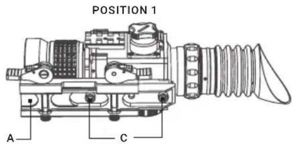
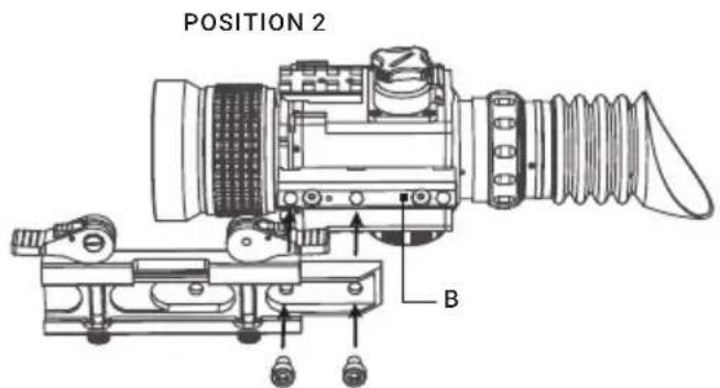
FIGURE 2-3. MOUNT ASSEMBLING
To install the Secutor on a Picatinny/ Weaver rail, perform the following:
- Unlock the clamping device of the scope mount by pushing down on the lever holders (A, see Figure 2-4) and unlocking the levers (B).
- Install the scope on the Picatinny/ Weaver rail so that the stops (C, see Figure 2-4) slides into the transverse slots on the rail.
- Affix the scope to the rail by locking the levers (B, Figure 2-4).
- Verify that the clamping device is firmly holding the Secutor. If necessary, adjust the clamping device's lever-cam locks as detailed in Part 2.1.3 (Clamping Device Adjustment).

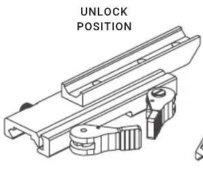
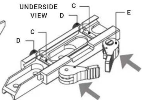
FIGURE 2-4. MOUNT
To provide you with greater flexibility in mounting Secutor weapon sight on the weapon, the dual lever mount can be installed in two different positions. On the bottom of the scope body there are two pairs of threaded mounting holes in the seating rail. You can shift the mounting position of your Secutor by an extra 1.5 inches backwards.
To change the position of Secutor mount, please follow the instructions below:
- Remove the two screws (C, Figure 2-3) that attach the mount (A, Figure 2-3) to the seating rail (B, Figure 2-3).
- Remove the mount.
- Change the position of the mount.
- Install the two screws into the mount and tight up the screws.
2.1.3 CLAMPING DEVICE ADJUSTMENT
To adjust the mount's clamping device, do the following:
- Remove the Secutor from the weapon.
- With the clamping device unlocked (as shown in Figure 2-4), push the cam (E) towards the arrow, which will cause the nut (D) to slide out of its hole.
- To tighten/ loosen the clamping device, push down on the cam (E) and turn the nut (D) CW/ CCW respectively, in one-two increments (see note below). Much like when the cam (E) is released, backward-moving springs will cause the nut (D) to slide back into its hole.
NOTE:
The eight-sided nuts of the mount lever-cam locks will only fit into their holes if turned in one of the discrete positions, using increments equal to 360°/8 .
- Verify that the adjusted lever-cam lock securely holds the weapon mounting rail.
- Repeat the procedure to adjust the clamping device's second lever-cam lock.
2.1.4 INSTALLING AN ADDITIONAL EQUIPMENT
Use the side Picatinny/Weaver rails to install any additional equipment, such as the HD Video Recorder, WiFi Attachment, or the Extended Battery Pack.
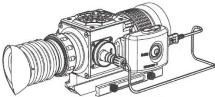
FIGURE 2-5. HD RECORDER INSTALLATION
2.1.5 CONNECTING AN ADDITIONAL EQUIPMENT
CAUTION:
Turn off the Secutor before you begin connecting/disconnecting any external equipment and before removing the batteries.
Remove the connectors protective cap (see Figure 1-2).
Connect a cable of the external 5V battery bank to the Secutor Micro-USB connector.
Connect a cable of HD Video Recorder, WiFi Attachment, or the Extended Battery Pack to the Secutor S620 universal connector.
Use the plug A (Figure 2-6) of a video cable to connect an external video recorder/monitor/TV to the Secutor. Connect the plug C of a video cable to the Secutor S620 universal connector.
Use the plug B of a video cable to connect an external power source (6 VDC / 600 mA) to the Secutor. Connect the plug C of a video cable to the Secutor S620 universal connector.

The external power supply must have a standard OD double-pole socket with a positive center contact.
CAUTION:
After removing the cable, replace the protective cap over the connector.
2.1.6 FASTENING THE REMOTE CONTROL TO WEAPON
Using Velcro tape, fasten the remote control to your weapon in an easily accessible place (e.g., on the front of the rifle stock).
Remove the connectors protective cap (see Figure 1-2).
Connect the cable of remote control to the connector of Securor.
2.2 CONTROLS AND DISPLAY INDICATIONS
2.2.1 CONTROLS
CAUTION:
DO NOT force the equipment controls past their stopping points.
The Secutor controls are shown in Figure 2-7 and are defined in Table 2-1. The ITEM column of the table indicate the numbers used to identify items in the figures.
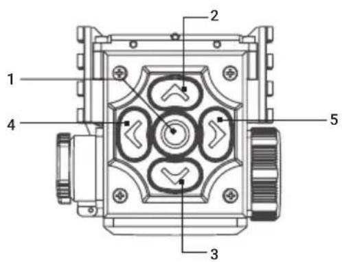
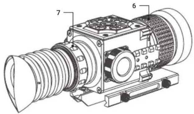
FIGURE 2-7. CONTROLS
TABLE 2-1. CONTROLS
| ITEMS | CONTROLS | OPERATING MODE | FIRST SHORT PRESS | LONG PRESS |
| 1 | ↓ Central Button | Real Time Image NUC | ON / OFFQuick Menu Exit | |
| Main Menu Confirm selection | ||||
| 2 | ↑ Up Button | Real Time Image NA | Enter Main MenuQuick Menu | |
| Main Menu | Change parameters | |||
| 3 | ↓ Down Button | Real Time Image | Bring out Quick Menu | NA |
| Quick Menu Change parameters | ||||
| Main Menu | Change parameters | |||
| 4 | ← Left Button | Real Time Image | Bring out Quick Menu | NA |
| Quick Menu | Switch function | |||
| Main Menu | Select setting options | |||
| 5 | → Right Button | Real Time Image | Bring out Quick Menu | NA |
| Quick Menu | Switch function | |||
| Main Menu | Select setting options | |||
| 6 | Focus Ring | Focuses the objective lens for the sharpest image | ||
| 7 | Eyepiece Focus Ring | Adjusts the diopter correction | ||
A five-button remote switch is included to operate and modify settings, in order to optimize the image without having to remove your hands from the weapon. Duplicates the functions of the control panel buttons.
NOTE:
Various display symbols indicating the current operating state of the Secutor can be displayed permanently, may appear momentarily, or can be set to appear only when a certain function is activated.
NOTE:
Each button is responsible for some functions selected by short press or long press the button. Pushing a button for 3+ second is considered "long press."
2.2.2 STATUS BAR
The status bar is located in the lower part of the display (Figure 2-8) and shows information about an actual operating status of the sight, including:
- Color palette: C1/C2/C3/...
- Zeroing profile A/B/C/D/E.
- Distance to the object.
- Current digital zoom magnification.
- Battery charge with current level in percent.
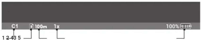
FIGURE 2-8. STATUS BAR
2.2.3 QUICK MENU
The Quick Menu allows change of basic settings. Enter the Quick menu with a short press of any of the buttons Down/Left/Right. To toggle between the functions below, press Left or Right button when Quick menu is in display. Use Up and Down buttons to change the selected item. Press the central button to exit Quick Menu. If select of Zoom, Palette, Brightness, Contrast, Sharpness functions do not take place in 5 second, the information disappear from display.

MANUAL (SILENT) CALIBRATION
Close the lens cover before calibration.
There is a mechanical shutter between the camera sensor and the lens. This shutter is used to perform a non-uniformity calibration (NUC). During NUC, the shutter presents a uniform temperature source to each detector element in the array. While imaging the flat-field source, the camera updates the offset correction coefficients, resulting in a more uniform image after the process is complete. All Secutor models allow for user to manually trigger or interrupt scheduled NUC function.

BRIGHTNESS
Press the Up/Down buttons to change image brightness from 0 to 9.

PALETTE
Basic image mode is "White Hot" (C1). Press the Up/Down buttons to select other palettes.

ZOOM
Press the Up/Down buttons to change digital zoom 1X/2X/4X/PIP.
Picture in inset window under PIP mode is 2X digital zoom.

CONTRAST
Press the Up/Down buttons to change display contrast from 0 to 9.

SHARPNESS
Select one of the sharpness aside (Normal/Smooth/Sharp) with a short press of Up / Down.

ADIAMETRIC RANGEFINDER
Secutor riflescopes are equipped with a stadiametric rangefinder which allows the user to estimate approximate distance to an object of known size.

FIGURE 2-9. STADIAMETRIC RANGEFINDER
You will see on the display: measurement bars, icons of three reference objects and respective distances for the three objects.
There are three pre-set reference objects:
Object 1 - height 0.3 m
Object 2 - height 0.7 m
Object 3 - height 1.7 m
The lower fixed bar under the object automatically appear on display, press the Up/Down buttons to move the upper horizontal bar until the object fits entirely between the two lines. The distance to the object is automatically recalculated as you move the upper line.
Press Left/Right buttons to choose reference object, press Middle button to exit rangefinder mode, range information will not disappear from display automatically.
Distance to the object displays in status bar and a “> < ” on reticle suggests the aiming point accordingly.
To select the unit of measurement (meters or yards), go to the respective menu option.
2.2.4 MAIN MENU
Enter the main menu with a long press of the Up button. Press the Left/Right buttons to select between the main menu options.
All menu is displayed in the central area of the image. The reason is the reduced field of view of the day sight by higher magnifications. Reaching a low battery state the device gives a warning in the top left corner of the central area.

Press the Up/Down button to Exit, the Main Menu will not disappear automatically.


TO NUC
Press the Up/Down button to turn Automatic Non-Uniformity Calibration On / Off. In the automatic mode the need for calibration is based on software algorithm, calibration starts automatically. When choose Off, user will do calibration manually by either lens cover(silent without shutter) or press middle button(with shutter). Manual calibration function is in Quick Menu.
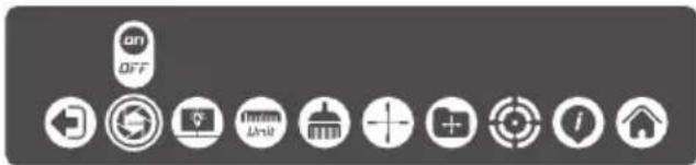

D BRIGHTNESS
Press the Up/Down buttons to change OLED brightness from 0, 1, 2.


Press Up/Down to select units of measurement from Yards and Meters.
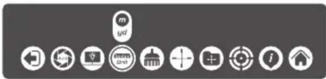

ECTIVE PIXEL REPAIR
Press Up/Down buttons then close lens cover to repair defective pixel. Defective pixels are found by software algorithm.


RETICLE
This main menu option allows you to select reticle shape and color. Enter submenu of "Reticle Setup" with a short press of Up/Down and you will see:
Select the desired reticle shape out of the list of 5 reticles with Up/Down. Press Right to move the Reticle Color selection.
Select the desired reticle color Black, White, Red, or Green with Up/Down. Press Right to move to back.
Press Up/Down to return to real time image with the reticle type and color you just chose.
M1 (25mm) M1 (50mm, 75mm)
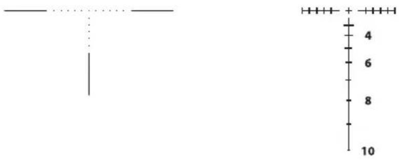
M2 (25mm) M2 (50mm, 75mm)

M3 (25mm) M3 (50mm, 75mm)

M4 (25mm, 50mm, 75mm) M5 (25mm, 50mm, 75mm)


OING PROFILE

Various profiles can be used when employing the sight on different rifles and when shooting different cartridges. Select one of the zeroing profiles (shown with letters A, B, C, D, E) with short press Up/Down. The name of selected profiles is displayed in the status bar.

OING

To zero your weapon, you need to set a zeroing distance first. You can zero your weapon at any distance range from 1 to 999m.
Enter submenu of "zeroing" with a short press of Up/Down and you will see:

Select profile icon Ⓐ and press Up/Down. You will see:

Set the distance value for each digit with press the Up/Down. Switch between the digits with a short press of Left/Right.
To clean the distance press Left/Right to move to 📋, then short press Up/Down.
To confirm distance press Left/Right to move to √, then short press Up/Down.
The distance you set shown above the status bar:

To add another distance, press Left/Right to move to profile icon ⏻. Select profile icon and repeat the operations described above.
NOTE:
Max number of zeroing distances is 5 for each profile.
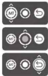
Press Up/Down on distance icon, you will see:

Take a shoot, move Up/Down/Left/Right to make cross center of reticle at point of impact. X, Y will show the distance value you move.
Press middle button to Freeze and you will see:

Save
Press Up/Down to Save, you will see indication:


Back
Press Left, then short press Up/Down to return.

Delete
Press Left/Right, then short press Up/Down to Delete, you will see indication:
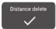
NOTE:
In order to get precise ballistic trajectory, zeroing in 3 distances and 3 shots in each distance is recommended, and your shortest distance should be no more than 100 meters.
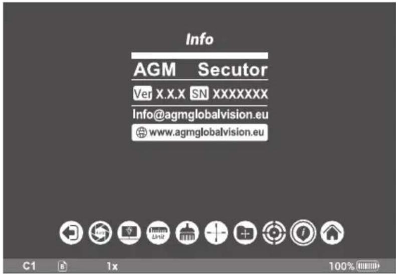
This option allows the user to view the following information about the imager.

SET (RESTORE DEFAULT SETTING)
Press Up/Down buttons to Restore Default Setting, there will be no further indication. The following settings will be restored to their original values before changes made by user:
- Electronic Zoom
- Image Brightness
- Image Contrast
- Image Sharpness
- OLED Brightness
2.3 OPERATING PROCEDURES
2.3.1 OPERATING
WARNING:
Always make sure your firearm is unloaded before you place the scope on the firearm. Reconfirm that the chamber is empty if you stop the procedure then resume later. Safe handling rules should be followed at all times.
CAUTION:
DO NOT force the equipment controls past their stopping points.
CAUTION:
To prevent thermal damage to the equipment, never point it, either powered or not, directly at the sun or any other source of high intensity light that the unprotected human eye cannot tolerate (such as a welding arc). To prevent inadvertent exposure to these sources, never leave the equipment without the objective lens cap secured.
Operating procedures are as follows:
- Remove the Secutor from the carrying case.
- Install the Secutor on the weapon's Picatinny/Weaver rail.
- Verify that the Secutor is securely mounted to the weapon.
- Remove the objective lens cap.
-
Point the equipment at an object.
-
Activate the Secutor by long press the central button. After approximately 4 sec, video of the thermal scene should appear.
-
Adjust the Secutor for your eyesight by turning the eyepiece focus ring CW up to the stop, and then CCW until the display and symbols (such as the reticle) are as clear as possible. Bring the object into focus by turning the objective focus ring (CW for far focus, CCW for near focus).
-
Using the QUICK MENU, configure the Secutor to adapt it to your situation.
For more information on operational setting procedures, see Part 2.2 (Controls and Display Indications).
A. Select the Image Palette.
B. Adjust the image brightness, contrast, and sharpness for your comfort.
C. Use digital zoom to magnify the central area of the displayed scene.
NOTE:
Digital zoom allows distant objects to appear larger; however, the resolution will be compromised.
NOTE:
Zooming does not affect the boresight.
D. Use Manual Calibration (Non-Uniformity Calibration - NUC) function to improve image quality. As the camera including the detector heats up during the use, the detector pixels will drift. The pixels do not drift uniformly. The camera software compensates for the drift up to an accurate position point, but when the limit is reached the NUC function is triggered. A uniform mechanical shutter is placed between the lens and the detector for a moment and the signal is processed.
Push the central button to manually trigger a NUC.
E. Adjust the necessary adjustment using the MAIN MENU. See Part 2.2.2 (Using the MAIN MENU).
F. Select a reticle pattern.
G. Select the color of the reticle.
NOTE:
Digital zoom and reticle color control help target detection and discrimination.
NOTE:
The reticles appear in the most recently saved position on the display.
- To align the barrel of the weapon, place the reticle on the desired target. To allow for the bullet's travel (i.e. bullet drop, windage, and the target mobility), use the boresight adjusting function.
CAUTION:
DO NOT leave the equipment activated when not in use.
2.3.2 BORE SIGHTING THE SECUTOR
WARNING:
Always make sure your firearm is unloaded before you place the scope on the firearm. Reconfirm that the chamber is empty if you stop the procedure then resume later. Safe handling rules should be followed at all times.
NOTE:
The Secutor must be zeroed each time it is mounted to a new weapon.
NOTE:
When reticle at (0-0) coordinates there is an incline of 15 arc minutes for the scope's optical axis.
Boresight the Secutor as follows:
- Locate a target at the fire adjustment range (100yd or 100m for example).
- Turn on the Secutor.
- Adjust the eyepiece and focus the objective lens to sharpen the image of the target.
- Adjust the brightness of the display.
- Select a reticle pattern.
-
Take aim by centering the reticle on the target and fire a series of shots (3-4).
-
Find the point of impact and measure its vertical and horizontal deviations from the center of the target.
- Work out the values of boresight correction required to compensate for the measured deviation of the point of impact from the center of the target. Table 2-2 contains the boresight correction values.
TABLE 2-2. BORESIGHT CORRECTIONS
| SECUTOR TS25 SECUTOR TS50 SECUTOR TS75 | ||
| Windage Adjustment Increment 1.7 | MOA 0.8 MOA 0.5 MOA | |
| Elevation Adjustment Increment 0.8 | MOA 0.4 MOA 0.2 MOA | |
- Use the ZEROING in Main Menu to apply corrections required to bring the point of impact as close as possible to the center of the target. See Part 2.2.4 (MAIN MENU).
- Fire a series of shots to check the boresight.
2.3.3 SECUTOR SHUT-DOWN
NOTE:
Shut down the Secutor properly to avoid losing unsaved settings and data.
Shut-down the Secutor as follows:
- Turn off the Secutor.
- Replace the cap on the objective lens.
- Disconnect the cable (if applicable).
- Place the cap on the connector.
- Dismount the Secutor from the weapon.
- Remove the batteries.
CAUTION:
Do not store the Secutor with the batteries still in it.
- Store the Secutor and all accessories in the carrying case.
3 MAINTENANCE INSTRUCTIONS
3.1 TROUBLESHOOTING
The purpose of troubleshooting is to identify the most frequent equipment malfunctions, probable causes, and corrective actions required.
Table 3-1 lists the common malfunctions that may be found during the operation or maintenance of the Secutor. Perform the tests/inspections and corrective actions in the order listed.
This table does not list all of the malfunctions that may occur with your device, or all of the tests and corrective actions that may be necessary. If you experience an equipment malfunction that is not listed, or is not fixed by the corrective actions listed in the table, please contact Customer Service center.
TABLE 3-1. TROUBLESHOOTING
| MALFUNCTION | PROBABLE CAUSE/ TEST/ INSPECTION | CORRECTIVE ACTION |
| The scope fails to activate. | Batteries are missing or improperly installed. | Insert batteries or install correctly. |
| Batteries are dead. Replace the batteries. | ||
| Batteries, surfaces or contacts are dirty or corroded. | Clean the contact surfaces with a pencil eraser and/or alcohol and cotton swabs. | |
| The equipment is damaged. Please contact Customer Support. | ||
| The scope is not responsive to control buttons. | The equipment is damaged. Please contact Customer Support. | |
| Poor image quality. | Check objective lens and eyepiece focus. | Refocus. |
| Check for fogging or dirt on objective lens and eyepiece. | Clean the lenses as detailed in Part 3.2.2. | |
| The equipment is damaged. Please contact Customer Support. | ||
| No image on an external monitor. | Video cable is damaged. Replace the video cable with a new one. Please contact Customer Support. | |
| The equipment is damaged. Please contact Customer Support. | ||
| Light is visible around eyecup. | Check eyecup resilience. If the eyecup is defective, please contact Customer Support. | |
3.2 MAINTENANCE
3.2.1 GENERAL
The Secutor operator maintenance consists of operational tests, inspections for unit serviceability, cleaning and mounting procedures, corrective actions (troubleshooting and replacement of a limited number of parts). Maintenance instructions covered elsewhere in this manual (Troubleshooting, etc.) are not repeated in this section.
CAUTION:
The Secutor is a precision electro-optical instrument and must be handled carefully at all times to prevent damage.
CAUTION:
DO NOT dismantle the equipment.
3.2.2 CLEANING PROCEDURES
Clean the Secutor and optional items as follows:
- Gently brush off any dirt from the equipment using only a clean, soft cloth.
- Moisten the cloth with fresh water and gently wipe the external surfaces (except for optical surfaces).
- Dry any wet surfaces (except for optical surfaces) with another clean, dry soft cloth.
- Using a lens brush, carefully remove all loose dirt from optical surfaces (objective lens and eyepiece).
- Slightly dampen a cotton swab with ethanol and lightly and slowly wipe optical surface. Clean the optical surface by circular movements from the center to the edge, not touching the lens holder and changing cotton swab after each circular stroke. Repeat until the optical surface is clean.
- Clean the battery contact surfaces and contact springs with a pencil eraser and/or alcohol and cotton swabs.
CAUTION:
Thoroughly dry each item before replacing into the storage/carrying case.
3.2.3 BORE SIGHTING
Perform the Secutor bore sighting:
— When the Secutor is mounted to a new weapon for the first time;
— After repair of the Secutor/weapon;
— As the need arises (in case of systematic inaccuracy and missing the target).
Refer to Part 2.3.2 for boresight procedure.
4 WARRANTY INFORMATION
4.1 WARRANTY INFORMATION AND REGISTRATION
4.1.1 WARRANTY INFORMATION
This product is guaranteed to be free from manufacturing defects in material and workmanship under normal use for a period of three (3) years from the date of purchase. In the event that a defect covered by the warranty below occurs during the applicable period stated above, AGM Global Vision, at its discretion, will either repair or replace the product; such action on the part of AGM Global Vision shall be the full extent of AGM Global Vision's liability, and the Customer's sole and exclusive reparation. This warranty does not cover a product if it has been (a) used in ways other than its normal and customary manner; (b) subjected to misuse; (c) subjected to alterations, modifications or repairs by the Customer or by any party other than AGM Global Vision without prior written consent of AGM Global Vision; (d) is the result of a special order or categorized as "close-out" merchandise or merchandise sold "as-is" by either AGM Global Vision or the AGM Global Vision dealer; or (e) merchandise that has been discontinued by the manufacturer and either parts or replacement units are not available due to reasons beyond the control of AGM Global Vision. AGM Global Vision shall not be responsible for any defects or damage that in AGM Global Vision's view are a result from the mishandling, abuse, misuse, improper storage or improper operation of the device, including use in conjunction with equipment that is electrically or mechanically incompatible with, or of inferior quality to, the product, as well as failure to maintain the environmental conditions specified by the manufacturer. This warranty is extended only to the original purchaser. Any breach of this warranty shall be enforced unless the customer notifies AGM Global Vision at the address noted below within the applicable warranty period.
The customer understands and agrees that except for the foregoing warranty, no other warranties written or oral, statutory, expressed or implied, including any implied warranty of merchantability or fitness for a particular purpose, shall apply to the product. All such implied warranties are hereby and expressly disclaimed.
4.1.2 LIMITATION OF LIABILITY
AGM Global Vision will not be liable for any claims, actions, suits, proceedings, costs, expenses, damages, or liabilities arising out of the use of this product. Operation and use of the product are the sole responsibility of the Customer. AGM Global Vision's sole undertaking is limited to providing the products and services outlined herein in accordance with the terms and conditions of this Agreement. The provision of products sold and services performed by AGM Global Vision to the Customer shall not be interpreted, construed, or regarded, either expressly or implied, as being for the benefit of or creating any obligation toward any third party of legal entity outside AGM Global Vision and the Customer; AGM Global Vision's obligations under this Agreement extend solely to the Customer. AGM Global Vision's liability hereunder for damages, regardless of the form or action, shall not exceed the fees or other charges paid to AGM Global Vision by the customer or customer's dealer. AGM Global Vision shall not, in any event, be liable for special, indirect, incidental, or consequential damages, including, but not limited to, lost income, lost revenue, or lost profit, whether such damages were foreseeable or not at the time of purchase, and whether or not such damages arise out of a breach of warranty, a breach of agreement, negligence, strict liability, or any other theory of liability.
4.1.3 PRODUCT REGISTRATION
In order to validate the warranty on your product, the customer must complete and submit AGM Global Vision PRODUCT REGISTRATION FORM on our website (www.agmglobalvision.com/customer-support).
4.1.4 OBTAINING WARRANTY SERVICE
To obtain warranty service on your unit, the End-user (Customer) must notify the AGM Global Vision service department via e-mail. Send any requests to support@agmglobalvision.com to receive a Return Merchandise Authorization number (RMA). When returning any device, please take the product to your retailer, or send the product, postage paid and with a copy of your sales receipt, to AGM Global Vision's service center at the address listed above. All merchandise must be fully insured with the correct postage; AGM Global Vision will not be responsible for improper postage or merchandise that becomes lost or damaged during shipment. When sending product back, please clearly write the RMA# on the outside of the shipping box. Please include a letter that indicates your RMA#, the Customer's Name, a Return Address, reason for the return, contact information (valid telephone numbers and/or an e-mail address), and proof of purchase that will help us to establish the valid start date of the warranty. Product merchandise returns that do not have an RMA# listed may be refused, or a significant delay in processing may occur. Estimated Warranty service time is 10-20 business days. The End-user/Customer is responsible for postage to AGM Global Vision for warranty service. AGM Global Vision will cover return postage/shipping after warranty repair to the End-user/Customer only if the product is covered by the aforementioned warranty. AGM Global Vision will return the product after warranty service by domestic UPS Ground service and/or domestic mail. Should any other requested, required, or international shipping methods be necessary, the postage/shipping fee will be the responsibility of the End-user/Customer.
For service, repair or replacement, please contact:
AGM Global Vision, LLC
173 West Main Street
PO Box 962
Springerville, AZ 85938
Tel. 928.333.4300
support@agmglobalvision.com
www.agmglobalvision.com
5 SPECIFICATIONS
5.1 SPECIFICATIONS
TABLE 5-1. SPECIFICATIONS
| SECUTOR TS25 SECUTOR TS50 SECUTOR TS75 | |||
| Magnification 1.2× 2.4× 3.6× | |||
| Objective Lens Type Germanium | |||
| Detector Type 17μm Uncooled | Microbolometer | ||
| Frame Rate 50 Hz | |||
| Resolution 384×288 | |||
| Display HD Display 1024x768 | |||
| Turn-on Time, max 4 sec | |||
| Digital Zoom | 1×, 2×, 4×, PIP | ||
| Temperature Imaging Modes (Image Palettes) | "White Hot", "Black Hot", and other color Image palettes | ||
| Reticle Type | 5-Pattern digitally controlled | ||
| Reticle Color | Black, White, Red, Cyan | ||
| Boresight Adjustment Type | Digitally controlled | ||
| Interfacing | • Micro-USB (Power bank 5V)• Universal S620 connector (Power In, Analog Video In/Out, Wi-Fi Attachment, HD Recorder, Extended Battery Pack) | ||
| Windage Adjustment Increment | 1.7 MOA | 0.8 MOA | 0.5 MOA |
| Elevation Adjustment Increment | 0.8 MOA | 0.4 MOA | 0.2 MOA |
| Optical Data | |||
| Objective Lens System | 25 mm; F/1.0 | 50 mm; F/1.0 | 75 mm; F/1.0 |
| Field of View (X × Y) | 15.0° × 11.2° | 7.5° × 5.6° | 5.0° × 3.7° |
| Eye Relief | 40 mm | ||
| Focusing Range | 10 m to inf. | ||
| Diopter Adjustment | Manual; ±5 diopter | ||
| Electrical Data | |||
| Battery | Two CR123A 3V Lithium batteries | ||
| Battery Life at 20°C (68°F) | Up to 5 hr. | ||
| External Power Supply | Power bank (5V) via Micro-USB port;Extended battery pack (additional operating time up to 8 hr.)or 6V/600 mA power supply via S620 universal connector | ||
| Mechanical Data | |||
| Weapon Mount Type Picatinny MIL-STD-1913 and Weaver rails | |||
| Overall Dimensions 250 × 70 × 82 mm(9.8 × 2.8 × 3.2 in) | 250 × 70 × 85 mm(9.8 × 2.8 × 3.3 in) | 270 × 93 × 102 mm(10.6 × 37 × 4.0 in) | |
| Dimensions w/o Eyecup | 166 × 70 × 82 mm(6.5 × 2.8 × 3.2 in) | 170 × 70 × 82 mm(6.7 × 2.8 × 3.2 in) | 192 × 89 × 100 mm(7.6 × 3.5 × 3.9 in) |
| Height of the Scope Axis above Rail | 42 mm (1.65 in) | ||
| Weight (w/o Batteries) 0.65 kg (1.43 lb) 0.7 kg (1.54 lb) 0.76 kg (1.67 lb) | |||
| Environmental Data | |||
| Operating Temperature -40°C to +50°C (-40°F to +122°F) | |||
| Storage Temperature -50°C to +70°C (-58°F to +158°F) | |||
| Recoil Resistance 700g | |||
| Environmental Rating | IP67 | ||
Specifications are subject to change without notice.
APPENDIX
A. SPARE PARTS LIST
The parts authorized by this list of spare parts are required for operator maintenance. The list includes parts that must be removed before replacing authorized parts.
The PART NO. column indicates the primary number used by the manufacturer, which controls the design and characteristics of the item in terms of its engineering drawings, specifications, standards, and inspection requirement, to identify an item.

FIGURE A-1. SECUTOR SPARE PARTS LIST
TABLE A-1. SECUTOR SPARE PARTS LIST
| ITEM DESCRIPTION PART NO. | ||
| 1 25mm Objective Lens Cap GOL25OBLCP | ||
| - 50mm Objective Lens Cap GOL50OBLCP | ||
| - 75mm Objective Lens Cap GOL75OBLCP | ||
| 2 25mm Objective Lens Assembly GOL25OBLAS | ||
| - 50mm Objective Lens Assembly GOL50OBLAS | ||
| - 75mm Objective Lens Assembly GOL75OBLAS | ||
| 3 Mount AGMTIDQRM2 | ||
| 4 Battery Cap AGMTIDBCP | ||
| 5 Connector Cap AGMTIDCNCP | ||
| 6 Eyepiece Assembly | AGMTIRIPAS | |
| 7 Eyecup AGMTIRECP | ||
| 8 Remote Control | AGMSCTRC | |
| 9 Side Picatinny/Weaver Rail | AGMTIDSPR | |
| 10 | Video Cable | AGMTIDVCB |
| 11 | Operation Manual | AGMSCTOM |
| 12 | Carrying Case | AGMRSCC |
NOTES
AGM Global Vision, LLC
MAIN OFFICE
173 West Main Street
PO Box 962
Springerville, AZ 85938
USA
Tel. +1.928.333.4300
info@agmglobalvision.com
www.agmglobalvision.com
EUROPEAN OFFICE
Andrey Lyapchev #7
Sofia, P.C. 1756
Bulgaria
Tel. +35.988.412.5573
info@agmglobalvision.eu
www.agmglobalvision.eu


- SECUTOR
- EXPORT INFORMATION
- LIST OF CONTENTS
- TITLE
- PAGE
- GENERAL INFORMATION 6
- OPERATING INSTRUCTIONS 11
- MAINTENANCE INSTRUCTIONS 27
- WARRANTY INFORMATION 29
- SPECIFICATIONS 31
- APPENDIX 33
- SAFETY SUMMARY
- WARNING
- CAUTION
- NOTES
- 1 GENERAL INFORMATION
- 1.1 SYSTEM DESCRIPTION
- NOTE
- 1.2 STANDARD COMPONENTS
- 1.3 OPTIONAL EQUIPMENT
- 1.4 KEY FEATURES
- 2 OPERATING INSTRUCTIONS
- 2.1 INSTALLATION AND MOUNTING
- 2.1.1 BAT SERIES INSTALL ATION
- 2.1.2 INSTALLING THE SECUTOR ON A PICATINNY/WEAVER RAIL
- 2.1.3 CLAMPING DEVICE ADJUSTMENT
- 2.1.4 INSTALLING AN ADDITIONAL EQUIPMENT
- 2.1.5 CONNECTING AN ADDITIONAL EQUIPMENT
- 2.1.6 FASTENING THE REMOTE CONTROL TO WEAPON
- 2.2 CONTROLS AND DISPLAY INDICATIONS
- 2.2.1 CONTROLS
- 2.2.2 STATUS BAR
- 2.2.3 QUICK MENU
- MANUAL (SILENT) CALIBRATION
- BRIGHTNESS
- PALETTE
- ZOOM
- CONTRAST
- SHARPNESS
- ADIAMETRIC RANGEFINDER
- 2.2.4 MAIN MENU
- TO NUC
- D BRIGHTNESS
- ECTIVE PIXEL REPAIR
- RETICLE
- OING PROFILE
- OING
- SAVE
- BACK
- DELETE
- SET (RESTORE DEFAULT SETTING)
- 2.3 OPERATING PROCEDURES
- 2.3.1 OPERATING
- 2.3.2 BORE SIGHTING THE SECUTOR
- 2.3.3 SECUTOR SHUT-DOWN
- 3 MAINTENANCE INSTRUCTIONS
- 3.1 TROUBLESHOOTING
- 3.2 MAINTENANCE
- 3.2.1 GENERAL
- 3.2.2 CLEANING PROCEDURES
- 3.2.3 BORE SIGHTING
- 4 WARRANTY INFORMATION
- 4.1 WARRANTY INFORMATION AND REGISTRATION
- 4.1.1 WARRANTY INFORMATION
- 4.1.2 LIMITATION OF LIABILITY
- 4.1.3 PRODUCT REGISTRATION
- 4.1.4 OBTAINING WARRANTY SERVICE
- 5 SPECIFICATIONS
- 5.1 SPECIFICATIONS
- APPENDIX
- SPARE PARTS LIST
- AGM GLOBAL VISION, LLC
- MAIN OFFICE
- EUROPEAN OFFICE
Brand : AGM
Model : Secutor Pro TS50-384
Category : Thermal camera