
Dual EnvVCA - Keyboard 4ms - Free user manual and instructions
Find the device manual for free Dual EnvVCA 4ms in PDF.


| Product Type | Dual Envelope Generator, Waveshaper, Slew Limiter, and VCA |
| Brand | 4ms |
| Model | Shaped Dual EnvVCA |
| Format | Eurorack 20HP |
| Depth | 0.95" (24mm) including power cable |
| Power Consumption | +12V: 255mA, -12V: 230mA |
| Audio Input Impedance | 100kΩ |
| Audio Output Impedance | 1kΩ |
| Frequency Response | DC to 20kHz, ±0.1dB |
| VCA Gain Range | -75dB to +1.0dB |
| Envelope Time Range | ~400μs to over 30 minutes per segment |
| Envelope Shapes | Exponential, Linear, Logarithmic |
| Trigger Threshold | Rising edge 1.25V |
| Follow Jack Range | 0V to +5V |
| Envelope Output Max | ±10V |
| Level Knob | Attenuverter, amplitude up to ±10V |
| Offset Knob | DC offset, ±10V range |
| CV Inputs | Time CV, Shape CV, VCA CV |
| Gate Outputs | EOR (End of Rise), EOF (End of Fall) |
| Protection | Reverse polarity protected |
| Power Connection | 10-pin Eurorack header (16-pin to bus board) |
Frequently Asked Questions - Dual EnvVCA 4ms
User questions about Dual EnvVCA 4ms
0 question about this device. Answer the ones you know or ask your own.
Ask a new question about this device
Download the instructions for your Keyboard in PDF format for free! Find your manual Dual EnvVCA - 4ms and take your electronic device back in hand. On this page are published all the documents necessary for the use of your device. Dual EnvVCA by 4ms.
USER MANUAL Dual EnvVCA 4ms
User Manual 1.0 - November 15, 2022

The Shaped Dual EnvVCA is a dual analog envelope generator, waveshaper, slew limiter, and VCA. Each of the two channels is identical and they can be used separately or together.
Shaped Dual EnvVCA features:
- Versatile linear, exponential, and logarithmic envelope generator/LFO
- Low-noise, low-distortion, DC-coupled linear VCAs
- Shape slider, CV jack and attenuverters for fading between Exponential, Linear, and Logarithmic envelope shapes without changing envelope timing
- 100% analog
- Sliders and range switches control Rise and Fall times from \~2ms (500Hz) to \~2 min.
• Time CV jack extends time range: \~400μs (2.5kHz) to \~1 hour.
• Independent attenuverters for Rise and Fall time
• Blue/Red lights indicate strength and polarity
• Cycle buttons for looping envelopes (LFO)
- Trigger input jack and switch for toggling between AR, ASR, and Cycle modes of triggering - EOR/F (End of Rise/Fall) gate outputs can be used to chain and sequence events
• Env Level and Offset knobs scale and shift ENV output without changing VCA volume
• Audio In and Out jacks for passing audio or CV through the VCA
• VCA CV inputs to use VCAs independently from the envelopes
• VCA gain internally connected to envelope output when VCA CV jack is left unpatched
- Follow input jacks allow for slew limiting, envelope following/sidechaining, ADSR, and exotic filtering effects
- Re-trig jumpers allow for re-triggering during rise phase
Table of Contents
Setting up your Shaped Dual EnvVCA....3
Controls and Jacks....3
Rise and Fall Time Ranges 6
Patch: Making Notes 7
Making Notes (basic) 7
Making Notes in Stereo 7
Synchronizing channels: Making Notes Using Triggers......8
Creating Stereo Motion....8
Using a Keyboard or Sequencer....9
Patch: Waveshaping 10
Modulating Waveshape 10
Different Waveshapes for Rise and Fall....11
Log Rise with Expo Fall 11
Any Combination of Shapes....11
Patch: Modulating Time....12
Rapid Bursts 12
Ratcheting....12
Patch: Making an Oscillator and Synth Drums....13
Making an Oscillator 13
Making a Kick Drum....13
Making other Synth Drum sounds....14
Self-patching ideas....15
Frequency Modulation (FM)....15
Chaotic FM 15
Utility Patches....15
Attenuator 15
Trigger Delay with Pulse Width control 15
Inverted Trigger Delay (With Pulse Width Control)....15
DC generator (Manual CV)....15
Creating Envelopes with Trig Jack and Switch, Cycle Button, and Follow Jack.16
Triggering with switch set to AR 16
Triggering with switch set to ASR 16
Triggering with RETRIG Jumper Off (Factory Default) 16
Triggering with RETRIG Jumper On....16
Cycle Button and Triggering with switch set to Cycle 16
Follow Jack with Gates....17
Fundamentals of the Follow Jack....17
Audio filter....18
Portamento/glide 18
Sidechaining (Envelope Following) 18
Using non-linear Shapes with Follow 19
Creating ADSR Envelopes 20
ADSR envelope....20
Table of Envelope Shapes 22
Using Offset and Level Knobs....23
RETRIG Jumper 23
Electrical and Mechanical Specifications 24
Setting up your Shaped Dual EnvVCA
- Power off your Eurorack system.
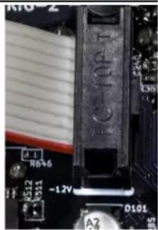
- On the back of the Shaped Dual EnvVCA you will see a 10-pin header. The 10-pin header connects to a Eurorack power header using the included power cable. Connect the 16-pin end of the power cable to a 16-pin Eurorack power header on your power supply distribution board and the 10-pin end to the Shaped Dual EnvVCA with the red stripe on the power cable oriented towards the bottom of the module.
- Using the included screws, securely attach the Shaped Dual EnvVCA to the rails of your case.
- Power on your Eurorack system.
Note: The Shaped Dual EnvVCA is reverse-polarity protected, but incorrectly connecting any module in any system can damage other modules on the power bus.
natural_image
Close-up of a computer motherboard with visible traces and components (no readable text or symbols)Controls and Jacks

Cycle
Cycle Buttons
The Cycle buttons toggle the cycling state for each channel. When cycling, the Shaped Dual EnvVCA behaves like an LFO, with an output waveform that continuously rises and falls. Each button illuminates orange to indicate the module is cycling. Note that pressing this button does not reset or alter an envelope that's already rising or falling.
Cycling can also be toggled with a gate signal using the Trig jack and switch (see below).
Rise/Fall Sliders and Switches
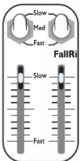
The Rise and Fall sliders control the rise and fall times of the envelope. Moving a slider up makes the rise or fall portion slower, moving it down makes it faster.
Each slider has a white light that indicates the current stage and output level of the envelope. When the envelope is in the rise stage, the Rise slider light will increase in brightness until the envelope hits its maximum. Once the peak is reached, the Rise light will turn off and the Fall light will turn on, decreasing in brightness as the envelope falls.
The Rise/Fall switches select the overall range of the sliders. Each slider has its own switch with three positions: Fast, Med, Slow.
When the switch is flipped to Fast, the envelopes go well into the audio range, allowing for classic AM, FM, and other fast modulation effects.
The middle position (Med) is designed for typical musical tempos, and can be useful when using the VCA to make notes at common BPMs.
The Slow position is geared for gradual fades and other slow LFO-style modulations.
See the Rise and Fall Time Ranges chart on page 6 for more information.

Time CV Jack and Rise/Fall CV Knobs
The Time CV jack modulates the Rise and Fall times of the envelope. The jack feeds two knobs: Rise CV, and Fall CV. Each of these knobs is an attenuverter (short for “attenuating inverter”) and controls how much the control voltage on the Time CV jack will affect the rise or the fall time.
Turning an attenuverter knob to the right of center means that a positive voltage on the Time CV jack will lengthen the rise/fall time and a negative voltage will shorten the rise/fall time.
Turning a knob to the left of center gives the opposite effect, meaning that a positive voltage on the Time CV jack will shorten the rise/fall time, while a
negative voltage will lengthen these durations.
The farther you turn the knob from center in either direction, the more effect incoming CV will have. When the knob is centered, the signal on the Time CV jack will have no effect on the rise or fall time.
Next to each knob is a light which indicates the strength and polarity of the modulation. The light will turn blue when the rise or fall time is being lengthened by CV, and red when the time is being shortened. The brighter the light, the more of an effect the CV is having. When the light is off, the Time CV jack has no effect on the envelope time.
When nothing is plugged into the Time CV jack, the knobs act as fine-tuning controls for the Rise and Fall times.

Shape Sliders and Lights
The Shape sliders smoothly crossfade between three different envelope shapes: exponential, linear and logarithmic, as indicated by the graphic above each slider. Changing the waveshape does not affect the rise or fall times. The color of the light above the slider indicates the current wave shape: green for exponential, red for linear, blue for logarithmic. Intermediate wave shapes are represented by a blend of these colors. The white light on the slider indicates the amplitude of the envelope, independent of the envelope Level and Offset settings.

Shape Jack and Shape Knob
Patching a CV signal into the Shape jack will control the waveshape of the envelope. The Shape knob is an attenuverter and controls how much the voltage on the Shape jack will change the envelope shape. When the Shape knob is to the right of center, positive voltage on the jack will cause the shape to become more logarithmic, while negative voltage will cause the shape to become more exponential. If the knob is to the left of center, the relationship is inverse. The farther from center the knob is positioned, the more effect incoming CV will have. When the knob is centered, CV on the jack will have no effect. When using the Shape knob or jack in combination with the Shape slider, the slider acts as a voltage offset. The Shape jack, knob, and slider can be used together to create waveforms with different shapes for the rise and fall segments. See Different Waveshapes for Rise and Fall on page 11 for more details.
ENV, Lin 5v, and OR Jacks
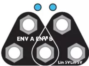
The ENV jacks output the waveshaped envelope for each channel. DC offset and vertical scale are determined by the positions of the Level and Offset knobs. Envelope shape is determined by the positions of the Shape slider and knob as well as CV applied to the Shape CV jack. The OR jack compares each side's ENV output signals and outputs the highest voltage value between the two at any given moment. The lights indicate the amplitude and polarity of each envelope. When the envelope is a positive voltage, its respective light will shine blue. When the envelope is a negative voltage, the light will shine red. The brightness of each light indicates the amplitude and offset of the outgoing signal, so when the light is off, this means the signal is outputting at or around 0V. The Lin 5V jacks output a linear waveshape from 0V to +5V, independent of Level, Offset, or Shape settings.

Level

Offset


Trig

ASR
Env. Level and Offset Knobs
The Level knob attenuates and inverts (attenuverts) the envelope output on each Env Out jack. When Offset is centered, turning Level fully clockwise will output a positive envelope, with a maximum peak of about 10V. Turning the knob counter-clockwise inverts the envelope; when fully counterclockwise, the output will peak at about -10V.
Turning the Offset knob clockwise will add a positive DC offset between 0V and 10V to the envelope, while turning the knob counter-clockwise will add a negative offset between 0V and -10V. See Using Level and Offset on page 23 for more details.
Note that neither the Level nor the Offset knobs affect the envelope going to the internal VCAs. For example, if the ENV output jack is patched to a modulation input on an external module while audio is running through the VCA, Level and Offset can be used to control the amount of modulation without changing the audio level or Lin 5V envelope signal.
Audio In, Audio Out, and VCA CV Jacks
The Audio In and Out jacks are the input and output of the VCA. The waveshaped envelope output (pre-Level and Offset knobs) is internally routed to the VCA CV input. When the envelope is stopped or at 0V, the Out jack will output silence. As the envelope rises, the signal will get louder until it becomes as loud as the input signal at the peak of the envelope. As the envelope falls, the signal will fade back to silence. Audio In B is normalized to Audio In A, as indicated by the graphics on the faceplate. So when Audio In B is unpatched, the Audio In A signal will be sent to both channels.
Patching into Audio In B will break this connection so that both channels are operating independently. The VCA is normalized to the waveshaped envelope, so adjusting the Shape slider and CV will affect the VCA.
When patched, the VCA CV jacks break the internal connection between envelope and VCA, allowing for independent use of the VCA. The VCA CV input has a range of 0 to 5V, which translates to nearly silent to unity gain.
The VCA has a linear response to the VCA CV, meaning that the voltage on the VCA CV jack directly sets the attenuation amount (e.g. 2.5V is about 50% attenuation).
Trig Jacks and Switches (Cycle, AR, ASR)
The Trig input jack and switch can be used with both gates and triggers in order to generate envelopes. The trigger switch selects the function of the jack: Cycle, AR or ASR.
When the switch is centered at AR (Attack Release), a trigger will initiate a single complete envelope if there is no envelope in progress. If the envelope is rising when a trigger is received, then the trigger is ignored (unless the RETRIG jumper is installed, see below). If the envelope is falling while a trigger is received, it will begin rising from its current voltage.
When the switch is flipped down to ASR (Attack Sustain Release), the envelope will behave similarly to AR mode, but will remain high for as long as the gate on the Trig jack remains high. Once the gate goes low, the envelope will switch to its release stage and begin falling. The envelope will always complete a full rise and fall stage, even if the gate goes low before the rise stage is done.
When the switch is flipped up to Cycle, a gate toggles the cycle state. If the Cycle button is off, a gate signal will turn the button on and make the channel cycle for as long as the gate is held high. If the Cycle button is on, then a gate signal will turn the button off and cease any cycling for as long as the gate is held high. See Cycle Button on page 16 for more information.
On the back of the module is a RETRIG jumper for each channel. When this jumper is installed, the envelope will immediately jump to 0V and start rising any time a trigger is received (regardless of the switch position). This can cause a click on the VCA output, so the jumper is not installed at the factory.

Follow Jack
The Follow jack is the input of a slew limiter, and can also be used for complex envelope generation, exotic audio filtering, envelope following and sidechaining.
Whenever the internal envelope is not triggered or cycling, the envelope output will rise or fall in order to match the voltage level present on the Follow jack. However, the rate of rise and fall times is limited by the positions of the Rise/Fall sliders and the CV amounts. That is, the envelope output will try to “follow” the signal present on the Follow jack, but it can only rise and fall as fast as the envelope would rise/fall if it were to be triggered. Since “slew” is the rate of change, we call this “slew limiting”.
The Follow jack can be used for envelope following, sidechaining, waveshaping, audio filtering, portamento and more. See Fundamentals of the Follow Jack on page 17 for more information.

EOR and EOF Output Jacks
The EOR (End of Rise) jack is specific to Channel A. It outputs a gate that goes high when the rise stage ends and the fall stage begins. It remains high as long as the envelope is falling, and goes low when the envelope completes. When the envelope is not running, the EOR jack will stay low. The EOR light will shine orange whenever the output is high.
The EOF (End of Fall) jack is specific to Channel B. It outputs a gate that goes high when the fall stage ends, and remains high until the envelope begins rising. Said another way, the gate at the EOF jack only goes low during the rise stage. The EOF light will shine orange when the EOF output is high.
Rise and Fall Time Ranges
| Switch Position | Slider Range (total env. time) | Max Range with CV (total env. time) | Use Cases | |
 | Slow | 2 min. to ~2Hz | ~30-60 min. to 2.5kHz | Gradual, slow fades or modulation changes occurring over the course of a long time. |
 | Med | ~10 sec. to ~30Hz | Generally suited for typical musical tempos. Useful for making notes, from snappy percussive sounds to long decays. The slower slider settings approach LFO ranges. | |
 | Fast | ~2Hz to ~500Hz | Good for using as an audio oscillator, or for FM, AM or other audio-rate modulation. Snappy attacks and sharp decays. | |
Note that the switch positions have little effect on the range obtained by using CV. This is intentional, to allow external modules control over the full range.
Because of its analog nature, the maximum and minimum rise and fall times vary from unit to unit. The table above shows typical values.
The rise and fall times will not necessarily be equal when the sliders are in the same position. For precisely equal rise and fall times, manual adjustment is usually needed.
Patch: Making Notes

Making Notes (Basic)
Patch a sound source into the Audio In A jack, and patch the Audio Out A jack to your mixer or amp so you can hear it on speakers or headphones. When choosing the sound source, try to find something that makes a continuous tone or drone, such as a VCO like the Ensemble Oscillator.
When the left Cycle button is on (button is shining orange), you should hear notes being played at a steady tempo. The notes should have a sharp attack (quick fade-in) and longer decay (slower fade-out).
Try moving the Rise slider up and listen to how the sound fades in more slowly. Then move the Fall slider down and hear how the fade-out gets faster. Continue to experiment with the slider positions, listening to how the sound and tempo change. Try flipping the switches to Fast and hear how much faster the envelope gets.
Adjusting the Shape slider to exponential will cause the rise and fall to sound more snappy while setting the slider to logarithmic will cause the envelope to sound more like a gate, with very quick rises and falls. Notice how adjusting the Shape slider does not affect the cycle tempo.
Next, patch the ENV output jack to a modulation input on the sound source. For example, if you're using the Ensemble Oscillator, try patching it to the Warp jack. For other VCOs, try a PWM or wave-shaper input. Adjust the Level and Offset knobs to control the amount of modulation. When both knobs are centered, you should hear no modulation.
Tip: If you want to use the Shape slider to control the waveshape of the modulation without changing the VCA, patch Lin 5V to VCA CV in order to bypass the internal connection between the shaped envelope and the VCA.
Making Notes in Stereo
So far we've just used Channel A, but this patch can be duplicated on Channel B to process two sound sources or a single stereo sound source. Try doing this now, by patching the second output of the Ensemble Oscillator or some other sound source into the Audio In B jack. If you don't have another
sound source, you could leave Audio In B unpatched and the signal from In A will be routed there automatically, but using a stereo sound source (or two mono sound sources) has a nicer effect. Patch the Audio Out B jack to the mixer (adjust the panning if your mixer supports that). Turn Channel B Cycle on. Adjust the Rise and Fall sliders and set the switches to center. You should hear both sound sources playing at different tempos.

Synchronizing Channels: Making Notes Using Triggers
With the previous patch, the tempo of each channel is linked to the rise and fall times of the envelopes. It's not possible, for example, to have quick, short notes at a slow tempo. It's also nearly impossible to adjust the sliders so both channels are going at the exact same tempo.
By turning Channel A's Cycle off and patching the EOF trigger from Channel B to Channel A's Trig jack, we can synchronize the channels and separate Channel A's envelope length from its tempo. Try doing this now. Flip Channel A's Trig switch to AR.
Every time Channel B ends an envelope and begins a new one, an EOF pulse fires, causing Channel A to start an envelope. Channel A's Rise/Fall sliders control the envelope length without changing the tempo. Channel B's sliders control the tempo for both channels as well as the envelope for Channel B.
Creating Stereo Motion
Since the channels are now synchronized, we can create motion in the stereo field. The effect is best if you use your mixer to pan the two Audio Outs to the left and right. You might also want to unpatch the Audio In B jack so that the same mono signal is used on both channels. Now play with the Rise/Fall and Shape sliders. Try increasing Channel A's Rise time by setting the slider just a little bit higher than Channel B. This gives Channel A a slight delay since it will take longer to rise than Channel B. The delay will be perceived as a right-to-left motion (assuming Channel A is in the left ear, and Channel B is in the right ear). Adjusting the Shape slider for either channel will also allow for some different stereo qualities. The key in this patch is to keep the channel envelopes similar, but different enough to create the illusion of motion.
Using a Keyboard or Sequencer
Instead of using Channel B to set the tempo, you could use an external CV/Gate keyboard or sequencer. Turn off Cycle and patch the gate output of the keyboard or sequencer into Channel B's Trig jack. Whenever you fire a gate by pressing a key, Channel B will fire an envelope, and also trigger Channel A. The tempo at which you play the keyboard or sequencer now determines the tempo of each channel's notes.
Keeping Channel A's Trig switch at AR, try Channel B's Trig switch in all three positions as you play notes on the keyboard or sequencer. Play with the duration of key-presses (or pulse width of sequencer step outputs), and see the effect this has on the sound in each Trig position. When Trig is set to Cycle, engage and dis-engage the Cycle button and note the effect this has when holding a key down.
If you're using a VCO as a sound source and you also want to control the pitch of the notes with the keyboard, patch the keyboard CV output to the pitch CV (1V/oct) input on the VCO.
Notice that when you fire a gate, Channel B will play first, and then Channel A. If you want them both to start at the same time, you could unpatch the cable from EOF to Channel A's Trig jack, and instead use a splitter or mult to patch the keyboard's gate output into both Channel's Trig jack.
Adding Chaos
You can create some inter-related pattens by patching Channel A's EOR jack into Channel B's Trigger jack. Re-patch EOF to Channel A's Trigger jack if you had removed it to use a keyboard. Turn off both Cycle buttons. Now both channels trigger each other. For some extra chaos, patch the OR jack to one of the Time CV jacks. Press one of the Cycle buttons to start the chain of events, and play with the sliders, the Rise/Fall CV knobs, and the Level and Offset knobs until you find sweet spots where random patterns emerge. You can also try adjusting the shape of either channel or flipping the Trig switch to different settings for more randomness.

Modulating Waveshape
A unique feature of the Shaped Dual EnvVCA is its ability to modulate the envelope waveshape without changing the timing. To demonstrate this, we'll create a simple patch that makes notes with Channel A and uses Channel B to modulate the waveshape of Channel A. Patch a sound source, such as the Ensemble Oscillator, into Audio In A. Patch Audio Out A to your mixer. Set Channel A's Rise/Fall sliders to taste. You should be hearing notes. If you have an oscilloscope, view the waveform on ENV A (adjust Level and Offset as needed). Move Channel A's Shape slider all the way to the left and listen to the exponential waveshape. Slowly move the slider to the right and listen how the sound changes. When you're done experimenting, set the slider all the way to the left. Set Channel B's switches to Slow and Rise/Fall sliders to center. Turn on Channel B's Cycle button. Make sure Channel B is going at least 10 times as slow as Channel A. Now patch Channel B's Lin 5V jack to Channel A's Shape jack. Turn Channel A's Shape attenuator knob all the way up. You should now be hearing the waveshape slowly change from exponential, to linear, to logarithmic, and back. Optionally, you can patch one of the Env outputs to modulate Twist or Warp on the Ensemble Oscillator. Using the OR output jack is particularly interesting in this case since different channels will be responsible for the modulation at different times. If you want to use a stereo signal, you can patch Channel A's ENV A jack to Channel B's VCA CV jack and adjust Channel A's Level and Offset knobs until the two channels sound balanced.

Log Rise With Expo Fall
In this patch we'll take advantage of the EOR jack to create separate waveshapes during the rise and fall portions of an envelope. It's common to use logarithmic rises with exponential falls in order to create snappy envelopes.
On Channel A, patch the EOR jack to the Shape CV Jack. Turn the Shape CV knob fully counterclockwise and set the Shape slider all the way to the right. Patch ENV A to a modulation input on another module. You also could patch a sound source into Audio In A and patch Audio Out A to a mixer.
During the rise phase, the EOR jack is low, so there is no Shape CV. The shape is set by the slider position, which is logarithmic. During the fall phase, the EOR jack sends a high voltage into the Shape CV jack. The Shape CV knob inverts this voltage, causing the shape to be exponential.
Any Combination of Shapes
Any combination of waveshapes can be set for rise and fall by first using Channel A's Shape slider to set the rise shape, and then using Channel A's Shape knob to set the fall shape. For instance, to create an exponential rise and logarithmic fall, simply reverse the settings by turning the Shape CV knob fully clockwise and moving the slider all the way left.
Channel B can also generate different waveshapes on the rise and fall by patching the EOF jack into Channel B's Shape CV jack. In this case, Channel B's Shape slider sets the fall shape, and Channel B's Shape knob sets the rise shape.
See the Table of Envelope Shapes on page 22 for an illustration of various waveshapes.
Patch: Modulating Time

Rapid Bursts
In this patch we'll make a rapid burst effect where the notes play at a steady tempo for a while, and then periodically play in a rapid burst. Start with Cycle on and the Audio In/Out jacks patched to a sound source and mixer. Set the Rise and Fall switches to Med, and set the sliders to taste. You should be hearing notes at a steady tempo. If you like, patch ENV A output to a modulation input on the sound source and adjust Level to set the amount of modulation.
Turn on Cycle for Channel B and adjust the Rise/Fall sliders and switches so that it's cycling at least four times as slowly as Channel A. Patch the EOF output of Channel B to the Time CV input of Channel A. Turn Channel A's Rise CV and Fall CV attenuverters slightly to the left, so that when the the EOF jack fires a pulse, the notes play at a faster rate.
Adjusting the Rise time of Channel B will change the pulse width of the EOF pulse, thus controlling the duration of the rapid bursts. The sum of the Rise and Fall times on Channel B controls how often the rapid bursts occur. Channel A's Rise and Fall CV knobs control how rapid the bursts are. Try adjusting these parameters slightly to hear the effect.
Ratcheting
The previous patch alternates between two speeds (normal and rapid). A ratcheting effect is when the speed gradually increases. To create this effect, unpatch the cable from EOF to Time CV, and instead patch Time CV to ENV B. Turn off Channel B's Cycle button and patch a slow trigger source (LFO, clock divider) to Channel B's Trig jack. Set Channel B's Trig switch to AR. Start with Channel B's Rise slider in the middle, Fall slider at Fast, and switches set to Med. Adjust Channel B's Level knob to set how much the speed increases.

Making an Oscillator
In this patch we'll use Channel A of the Shaped Dual EnvVCA as an oscillator. Flip the Rise and Fall switches of Channel A to Fast. Patch the ENV A output jack to a mixer. Engage the Cycle button to begin oscillation. Channel A's Level sets the volume. You can change the pitch by adjusting the Rise/Fall sliders. If both sliders are approximately at the same position and Shape is in the center, you'll get a triangle wave output. If one slider is substantially higher or lower than the other, the output will resemble a ramp or saw wave. For pulse wave shapes, you can take the signal from the EOR jack instead of ENV A, and then adjusting the sliders separately will change the pulse width. Adjusting the Shape slider on Channel A will change the timbre.
Making a Kick Drum
To make a kick drum sound, first use the sliders to set the pitch of Channel A low enough so that you can't hear sound. If there's some clicking, that's OK. Now we will modulate the pitch by patching ENV B to Channel A's Time CV jack. Set Channel A's Rise and Fall CV attenuverters to be fully CCW. Turn on Channel B's Cycle button or fire triggers into Channel B's Trigger jack to hear the pitch of Channel A modulate. Adjusting the Level knob on Channel B will change the amount the pitch rises; typically for a classic analog kick sound, the knob should be around 1 or 2 o'clock. The Rise and Fall sliders of Channel B will adjust the attack and decay. A typical drum will have a sharp attack and slower decay, so start with the Rise slider and switch at Fast, and the Fall slider and switch in the middle positions. The base pitch of the drum can be fine-tuned with Channel B's Offset knob.
An exponential modulation curve makes a more extreme kick drum sound. Try adjusting Channel B's Shape slider to the left and notice how the drum has more "punch".
Making Other Synth Drum Sounds

In the Making an Oscillator patch, we created a kick drum which decays to an inaudible frequency below the range of human hearing. To create a higher-pitched drum, such as a tom-tom, we will need a VCA to cut off the audio after the drum decays. Using a VCA also gets rid of the clicking between drum hits which happens when not using a triangle wave.
Raise the pitch of Channel A using the sliders or Channel B's Offset knob. You should hear a steady tone between Channel B firing (this is especially noticeable if you're using external triggers). Now we'll route this sound through Channel B's VCA. Unpatch the cable going to the mixer and patch it into Audio Out B instead. Patch a cable from ENV A to Audio In B. Now you should hear a similar synth drum sound, but it will be silent between hits.
Try setting Channel B's Shape slider to various positions left of center and listen how the "punch" of the drum changes. As you do this, you may need to adjust Channel B's Offset knob to keep the pitch in the desired range. You may also want to patch Channel B's Lin 5V to its VCA CV so that the VCA's response doesn't change as you adjust the Shape slider.
To get more complex waveshapes, patch EOR to Channel A's Shape CV jack and adjust the Shape knob (see Different Waveshapes for Rise and Fall patch on page 11)
To add some noise to the drum sound, you can patch an external oscillator into Audio In A. Then move the patch cable going from ENV A to Audio In B so that it goes from Audio Out A to Audio In B. The external oscillator will be amplitude modulated (AM) with the synth drum sound, and this resulting sound will be VCA'ed with Channel B's envelope. Play with Channel A's sliders and Rise/Fall CV knobs to hear the range of possible sounds. Next, use the OR output jack to modulate the external oscillator in time with the synth sound.
Try adding slight modulation to the Time CV or Shape CV of Channel B to create organic, naturally changing drum sounds. A slow LFO or a CV sequencer will work nicely.
Self-patching ideas
Frequency Modulation (FM)
Turn both Cycle buttons on, and set all switches to Fast. Start with all sliders in the center position. Use Channel B to modulate the frequency of Channel A by patching ENV B into Channel A's Time CV jack. Adjust both Rise and Fall CV knobs to around 9:00. Turn both Level knobs fully clockwise and center Offset knobs. Listen to the output on ENV A, or for a mix of both oscillators, use OR jack. Slowly adjust Channel B's sliders and listen to how the sound changes. Then slowly adjust Channel A's sliders and Rise/Fall CV knobs to hear the effect.
The Rise and Fall sliders of Channel B control the modulation frequency, and Channel A's Rise/Fall CV knobs control the modulation amount. Channel A's sliders control the base frequency, also known as the carrier frequency.
Chaotic FM
For chaos, start with the FM patch above, and then use Channel A to modulate Channel B by patching ENV A into Channel B's Time CV. Start with Channel B's Rise and Fall CV knobs set to about 10:00. Take the output from the OR jack. To find interesting chaotic sounds, you probably will need to move the sliders to a slower position and the Rise/Fall CV knobs more towards center than in the FM patch.
Utility Patches
Attenuator
Patch a signal that you want to attenuate into Audio In (either channel), and take the output from Audio Out. Patch the channel's ENV output to VCA CV. Use Offset to adjust the attenuation amount. Keep in mind that the VCA only responds to positive CV, so if Offset is anywhere left of center, the output will be silent. If you are using the envelope portion of the channel (Cycle is on or you are triggering the channel), set Level to center or else the envelope will bleed into the attenuator output.
Trigger Delay With Pulse Width Control
Turn Channel A's Cycle off. Send a trigger into Channel A's Trig jack and flip the Trig switch to AR. Take the output from EOR. Adjust the Rise slider and switch to set the trigger delay time (rising edge of incoming trigger to rising edge of outgoing trigger). Set the Fall slider and switch to control the width of the outgoing trigger. If you flip the Trig switch to ASR, the trigger output will be delayed from the falling edge of the incoming trigger, and rise times shorter than the incoming trigger's pulse width will not have an effect.
Inverted Trigger Delay (With Pulse Width Control)
Same as the previous patch, but use Channel B's Trig jack and EOF. Rise controls the amount of delay (rising edge of incoming trigger to falling edge of outgoing inverted trigger) and Fall controls the width of the inverted trigger.
DC generator (Manual CV)
When a channel is not running, the Offset knob will produce a steady DC voltage on the ENV output jack. If the channel is running, set Level to center or else the envelope will bleed into the output.
Ducking (Sidechaining)
A ducking effect reduces the volume of a sound at the same time a secondary sound plays. If the secondary sound is generated by triggers in your patch, you can easily create this on the Shaped Dual EnvVCA by generating an inverted envelope and patching it into the VCA. To achieve this effect, split the trigger that's triggering the secondary sound and patch it into the Trig jack of one channel. Turn Cycle off. Adjust Rise and Fall to create the envelope you want (typically the rise will be shorter than the fall). Patch an audio signal into Audio In and take the output from Audio Out. You should hear your sound play every time the trigger fires. In order to create the inverse behavior (get more quiet when the trigger fires), patch the ENV output to VCA CV, turn Level to about 9:00 and Offset to about 3:00.
If the secondary sound source is not generated by triggers in your patch (perhaps because it's an audio track), you can, see Sidechaining (Envelope Following) on page 18.
There are several ways to generate an envelope with the Shaped Dual EnvVCA: using the Trig jack and switch, pressing the Cycle button or using the Follow jack.
Triggering With Switch Set To AR
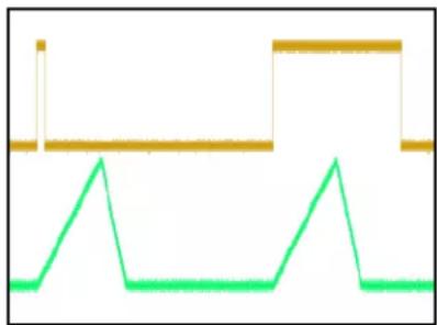
When the switch is set to AR, the Trig jack starts an envelope when it receives a trigger or gate. It only responds to rising edges. Figure 1 shows how a long or short pulse will cause identical envelopes since the pulse width and falling edge of the signal are ignored.
Triggering With Switch Set to ASR
An ASR (attack-sustain-release) envelope is trapezoidal, with a rising slope (attack), a flat plateau (sustain), and a falling slope (release). See Figure 2. The width of the sustain stage is controlled by the width of the gate input, the longer a gate is held high, the longer the sustain stage. If the gate input goes low before the rise stage completes, there will be no sustain, as the first pulse in Figure 2 illustrates.
Triggering With RETRIG Jumper Off (Factory Default)
If the envelope is already rising when a trigger is received, then the trigger is ignored (unless the RETRIG jumper is installed). If the envelope is falling when a trigger is received, it will begin rising from its current voltage. Figure 3 demonstrates this: the fifth and seventh triggers occur while the envelope is falling and cause it to begin rising mid-fall. The rest of the triggers either occur while the envelope is rising and are ignored, or while the envelope is not running, causing it to start.
Triggering With RETRIG Jumper On
Figure 4 shows how the RETRIG jumper changes the behavior. With the jumper installed, a trigger will always reset the envelope to zero and begin rising, regardless the stage of the envelope. This sharp transition to 0V can cause a click when used with audio, so the jumper is not installed by default.
Cycle Button and Triggering With Switch Set To Cycle
The Cycle button is a simple way to initiate an envelope. When the button is on, envelopes will cycle continuously. The button is latching, so pressing it once will make the module output envelopes until you press the button again. Once an envelope begins, pressing the Cycle button again will not immediately stop the envelope. Instead, the envelope will stop after finishing its fall stage.
When the Trig switch is set to Cycle, a high gate on the Trig jack toggles the cycling state. This works in tandem with the Cycle button. If a channel's button is initially off, a gate signal at the Trig jack will toggle it on. If the button is initially on, a gate at the jack will toggle it off. The Cycle button will shine orange whenever the combination of Trig jack and Cycle button causes the envelopes to cycle. Note that envelopes generated when the Trig switch is set to Cycle do not have a sustain portion.
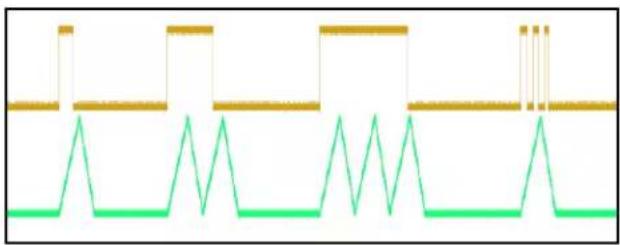
In Figure 5, the Cycle button is initially off, and the incoming gate signal on the Trig jack causes the envelope to cycle for as long as the gate is high. In this case, as the pulse width of the gate signal gets wider, the channel outputs more cycles.
natural_image
Pure electrical circuit lines without any symbolsFigure 1: AR – Trigger width does not change Env output.

natural_image
Pure electrical circuit lines without any symbolsFigure 2: ASR – Trigger width controls sustain length

Figure 3: RETRIG jumper off. Triggers on rise stage have no effect. Triggers on fall stage switch to rising.

natural_image
Pure electrical circuit lines without any symbolsFigure 4: RETRIG jumper installed. Triggers always restart the envelope.
natural_image
Pure electrical circuit lines without any symbolsFigure 5: When Cycle button is off, high gate on Trig jack makes envelope run (switch set to Cycle).

natural_image
Pure electrical circuit lines without any symbolsFigure 6: When Cycle button is on, high gate on Trig jack makes envelope stop (switch set to Cycle).
Figure 6 shows the opposite state; the Cycle button is initially on, so the incoming gate signal stops cycling for as long as the gate is high. In this case, as the pulse width of the gate signal gets wider, there are longer pauses between groups of envelopes.
Note that the first pulse in Figure 6 does not stop the envelopes, and the three rapid pulses in Figure 5 only cause one envelope. This illustrates an important aspect of the Shaped Dual EnvVCA: the state of the Cycle button and Trig jack when the switch is set to Cycle only matter when the envelope is stopped (at 0V). Any combination of gates and button presses while the envelope is running have no effect; it's only when the envelope finishes running that the Cycle jack or button can make it cycle again.
Follow Jack With Gates
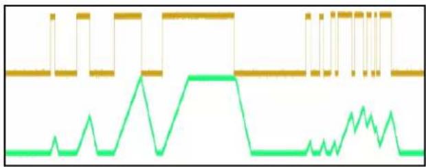
Figure 7 illustrates the use of gates on the Follow jack. A gate signal will cause the envelope to rise as long as the gate is high. When the gate goes low, the envelope will fall.
The fourth gate in Figure 7 shows that if the gate is held high while the envelope reaches its maximum, the envelope will hold (sustain) until the gate is released. This is an alternative way to create an ASR envelope (Attack Sustain Release) independent of the Trig switch position.
The short burst of pulses at the end illustrates how the Follow jack can be utilized to create complex envelope shapes using only a sequence of gates.
line
| Time | Green Line Value | Yellow Line Value | |------|------------------|-------------------| | 0 | 0 | 1 | | 1 | 0 | 1 | | 2 | 0 | 1 | | 3 | 0 | 1 | | 4 | 0 | 1 | | 5 | 0 | 1 | | 6 | 0 | 1 | | 7 | 0 | 1 | | 8 | 0 | 1 | | 9 | 0 | 1 | | 10 | 0 | 1 | | 11 | 0 | 1 | | 12 | 0 | 1 | | 13 | 0 | 1 | | 14 | 0 | 1 | | 15 | 0 | 1 | | 16 | 0 | 1 | | 17 | 0 | 1 | | 18 | 0 | 1 | | 19 | 0 | 1 | | 20 | 0 | 1 | | 21 | 0 | 1 | | 22 | 0 | 1 | | 23 | 0 | 1 | | 24 | 0 | 1 | | 25 | 0 | 1 | | 26 | 0 | 1 | | 27 | 0 | 1 | | 28 | 0 | 1 | | 29 | 0 | 1 | | 30 | 0 | 1 | | 31 | 0 | 1 | | 32 | 0 | 1 | | 33 | 0 | 1 | | 34 | 0 | 1 | | 35 | 0 | 1 | | 36 | 0 | 1 | | 37 | 0 | 1 | | 38 | 0 | 1 | | 39 | 0 | 1 | | 40 | 0 | 1 | | 41 | 0 | 1 | | 42 | 0 | 1 | | 43 | 0 | 1 | | 44 | 0 | 1 | | 45 | 0 | 1 | | 46 | 0 | 1 | | 47 | 0 | 1 | | 48 | 0 | 1 | | 49 | 0 | 1 | | 50 | 0 | 1 | | ... (Repeated) | ... (Repeated) | ... (Repeated) | The repeated 'Repeated' marks at each data point on the x-axis. The 'Unrepeated' marks at each data point.Figure 7: Sending gates into the Follow jack. When the input gate goes high, the envelope rises; when the input goes low, the envelope falls.
The Follow jack can be used with more than gates, see the next section for a detailed discussion.
Fundamentals of the Follow Jack
The Follow jack causes an envelope to rise or fall in order to "follow" the signal on the jack. Sending a high voltage (5V) into the Follow jack will cause the envelope to rise. Sending a low voltage (0V) will cause it to fall. This can be seen in Figure 7 of the previous section.
Sending voltages up to 5V, such as a waveform from an LFO or an audio signal, will have more complex effects.
There are two basic rules that govern this jack:
Rule 1: If the voltage on the Follow jack is greater than the envelope voltage, the envelope will rise; if the voltage on the Follow jack is less than the envelope voltage, the envelope will fall.
That is, the envelope will always “seek” the Follow signal: it will go up if the Follow signal is higher, and it will go down if the Follow signal is lower. This is where the term “follow” originates.
Rule 2: The envelope can only rise and fall at the speed set by the Rise/Fall controls and CV.
This means that if the Follow jack suddenly jumps up (for example, when a gate is applied), the envelope will try to follow that jump by rising, but it can only rise as fast as the controls allow it. The rate of change, or slew, is limited, thus we call the Follow circuit a “slew limiter”.
Note that the term “envelope voltage” in Rule 1 refers to the internal envelope voltage, which is the signal on the Lin 5V jack. The is the envelope before the Shape controls, Level and Offset knobs, and ENV jack output driver. This envelope has a maximum of 5V and minimum of 0V, which is why the Follow jack only responds to voltages from 0V to 5V. The ENV jack’s output driver doubles the internal voltage, so a 5V internal envelope corresponds to approximately 10V envelope on the ENV output jack when Level is set to maximum and Offset is centered.
Armed with these two basic rules, we can now showcase some advanced uses for the Follow jack in the following sections.
Audio Filter
The Follow jack can be used as an exotic audio low-pass filter by taking advantage of its slew-limiting properties. First, the audio signal must be shifted up such that it's within the range of 0V to 5V. Typically a level shifter can be used to add the required DC offset. You may also need to attenuate the audio so that it's no more than 5V. Any signal outside this range will be clipped, resulting in harsh distortion.
Patch this adjusted audio into the Follow jack. Patch the ENV output jack to your mixer/amp. Turn Level all the way up and turn Offset to center. To start, set the Rise/Fall sliders and switches to the fastest positions. Send a steady positive voltage into the Time CV jack and turn the Rise/Fall CV knobs all the way down.
At this point you should be hearing an audio signal that is similar to the original signal. Now make the rise and fall times slower by adjusting the Rise/Fall CV knobs and sliders, or by adjusting the CV patched into the Time CV jack. As you do this, you should hear the audio get more muffled, as the slew becomes limited and higher frequencies can no longer pass. To make more exotic sounds, try only adjusting the rise or the fall time. This will let the rising portions and falling portions of higher frequencies pass differently, creating some unique harmonics.
Waveshaper
By limiting the slew, wave shapes with sharper transitions can be altered to have smoother transitions. For instance, feeding a square wave into the Follow jack will produce a trapezoidal or triangular wave on the ENV output jack. Adjust the Rise/Fall sliders and switches to get a maximum amplitude output waveform while still performing the desired amount of waveshaping. These controls will need to be re-adjusted if the frequency of the waveform changes. You may be able to use the Time CV jack and Rise/Fall CV knobs to track the frequency and create a somewhat consistent variable-frequency wave shaper. You can also change the curve of a wave using the Shape slider.
Portamento/Glide
The output of a CV/Gate keyboard or a sequencer is often a step-wave, meaning that the voltage jumps (or “steps”) from one voltage to the next as the notes are played. When this is patched into a VCO, the result is a sequence of notes that jump from one pitch to the next. Adding in some slew causes the notes to “glide” from one pitch to the next. This effect is known as portamento or glissando. The Shaped Dual EnvVCA can perform this effect by patching the step-wave into the Follow jack and taking the output from the ENV output jack. The amount of glide effect is controlled by the rise and fall times. If you’re patched into the pitch input of a VCO, you can adjust the tuning with the Level and Offset knobs. Keep in mind that the Shaped Dual EnvVCA is not designed to be a precision portamento effect, so tuning will not be accurate over a wide range.
Sidechaining (Envelope Following)
The Follow jack can be used to create an envelope that follows an audio signal's envelope. This envelope can be inverted and used to control a VCA, creating a “ducking” effect on another sound. This technique is called sidechaining.
A common application is to use a kick drum to duck another sound source, for example, a background drone. Patch an audio source that's making a kick drum sound into the Follow jack of Channel B. Make sure Cycle is off. Start with the switches at Med, the Rise slider all the way down, and the Fall slider in the center. If you turn Level up, the ENV B jack will be outputting an envelope that roughly follows the kick drum's envelope. Adjusting Rise and Fall will control the attack and release of the envelope, that is, how quickly the envelope responds to the attack and release of the kick drum.
For this example we want to invert the envelope, so turn Level all the way counter-clockwise, and turn Offset to around 2:00. ENV B will now be outputting an inverted envelope that rests at about 5V and then ducks down when the kick drum plays. Patch this inverted envelope into Channel A's VCA CV jack. Run the audio that you want to be ducked (e.g. a drone sound) into Channel A's Audio In, and listen to the output on Audio Out. You should hear the drone play at normal volume, and then briefly get more quiet whenever the kick drum fires. Try listening to the drone and the kick drum simultaneously to get the full effect.
Adjust Channel B's Rise and Fall sliders to control how quickly the envelope responds. If the sliders are set too fast, the envelope will trace the individual peaks of the sound wave, not the overall envelope, and the result will be like a subtle AM effect. If the sliders are set too slow, the volume won't change much when the kick drum fires.
You can also adjust Channel B's Offset and Level knobs to control the dynamic range of the ducking. If you want less ducking, turn Level towards center to reduce the amplitude of the envelope. On the other hand, if the kick drum is quiet you may need to turn Level towards the extreme counter-clockwise position to generate an envelope with enough amplitude to get the amount of ducking you want. Offset almost always needs to be between 1:00 and 3:00. If it's too low, the output will be too quiet, and if it's too high, the output will be at maximum volume with very little ducking.
Using Non-Linear Shapes With Follow
When you feed a signal into the Follow jack, the ENV output jack produces different waveforms depending on the Shape settings. Figure 8 illustrates variation between the outputs with the Shape slider in different positions. The blue trace is an audio recording of three drum hits, which is fed into the Follow jack. The magenta trace shows the output when Shape is set to linear: the peaks of this output are roughly proportional to the peak levels of the input signal.
Since exponential curves change a small amount to small signals, and a large amount to large signals, when Shape is exponential, low voltages (near 0V) will be diminished, and higher voltages (near 5V) will be amplified. This can be seen by the orange curve in Figure 8: only the loudest peaks of the blue trace cause any noticeable output.
On the other hand, logarithmic curves change a large amount to small signals, and a small amount to large signals. Setting Shape to this curve produces the green trace: tiny signals cause relatively large peaks in the output, while large differences in the input peaks cause little differences in the output peaks.
These differences between Shape settings when using the Follow jack can be used to select the types of signals you want a channel to respond to. For example, if you want to only output an envelope when a loud kick drum occurs, then using an exponential shape would be the best choice. On the other hand, if you wanted a signal that responds to loud and quite signals with relative equality, a logarithmic shape would be the better option.

line
| Time | Signal 1 | Signal 2 | Signal 3 | Signal 4 | |------|----------|----------|----------|----------| | 0 | 0.0 | 0.0 | 0.0 | 0.0 | | 1 | 0.5 | 0.3 | 0.1 | 0.05 | | 2 | 0.8 | 0.6 | 0.2 | 0.1 | | 3 | 0.6 | 0.7 | 0.3 | 0.15 | | 4 | 0.9 | 0.8 | 0.4 | 0.2 | | 5 | 0.7 | 0.9 | 0.5 | 0.25 | | 6 | 0.8 | 0.8 | 0.6 | 0.3 | | 7 | 0.6 | 0.7 | 0.7 | 0.35 | | 8 | 0.9 | 0.8 | 0.8 | 0.4 | | 9 | 0.7 | 0.6 | 0.9 | 0.45 | | 10 | 0.8 | 0.7 | 0.8 | 0.5 | | 11 | 0.6 | 0.5 | 0.7 | 0.55 | | 12 | 0.9 | 0.8 | 0.9 | 0.6 | | 13 | 0.7 | 0.6 | 0.8 | 0.65 | | 14 | 0.8 | 0.7 | 0.9 | 0.7 | | 15 | 0.6 | 0.5 | 0.8 | 0.75 | | 16 | 0.9 | 0.8 | 0.9 | 0.8 | | 17 | 0.7 | 0.6 | 0.8 | 0.85 | | 18 | 0.8 | 0.7 | 0.9 | 0.9 | | 19 | 0.6 | 0.5 | 0.8 | 0.95 | | 20 | 0.9 | 0.8 | 0.9 | 1.0 | | 21 | 0.7 | 0.6 | 0.8 | 1.05 | | 22 | 0.8 | 0.7 | 0.9 | 1.1 | | 23 | 0.6 | 0.5 | 0.8 | 1.15 | | 24 | 0.9 | 0.8 | 0.9 | 1.2 | | 25 | 0.7 | 0.6 | 0.8 | 1.25 | | 26 | 0.8 | 0.7 | 0.9 | 1.3 | | 27 | 0.6 | 0.5 | 0.8 | 1.35 | | 28 | 0.9 | 0.8 | 0.9 | 1.4 | | 29 | 0.7 | 0.6 | 0.8 | 1.45 | | 30 | 0.8 | 0.7 | 0.9 | 1.5 | | ... (repeated) | ... | ... | ... | ... | | Final Value (approx.)Figure 8: Blue is audio fed into Follow jack. Magenta is ENV output with linear shape; orange is expo shape; green is log shape.
Creating ADSR Envelopes

ADSR Envelope
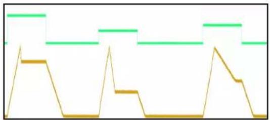
An ADSR (attack-decay-sustain-release) envelope is like an ASR envelope, except that it adds a fourth stage known as “decay” after the attack stage. After hitting the peak, an ADSR envelope “decays” to a sustain level less than the peak level. See Figure 9. This sustain level and the speed at which the envelope decays are controllable.
We can generate an ADSR envelope with the Shaped Dual EnvVCA by feeding a gate into both Trig jacks. The gate should be generated by an external module such as a keyboard or sequencer that lets you control the pulse width. The pulse width determines the length of the sustain, that is, the ADSR envelope will do the attack and decay segments and then hold at the sustain level until the gate goes low. At that point it'll do the release segment.
natural_image
Abstract line pattern with green and gold step-like shapes (no text or symbols)Figure 9: ADSR. Ch B Level knob turned down in 2nd envelope to lower sustain level. Ch A Fall slider moved up in third envelope to make decay slower.
Use a mult or stackable cable to patch the gate signal into both Trig jacks. Flip Channel A's Trig switch to AR, and Channel B to ASR. Both Cycle buttons should be off.
Set all Rise/Fall switches to Med. Channel A's Rise will control the attack time, set it to Fast to start. Set Channel B's Rise to match Channel A's: in order to produce a true ADSR envelope both Rise sliders must always be set the same. Channel A's Fall will control the release time, start with it a few marks above Fast. Channel B's Fall will control the decay time, start with it around the center position.
Set both Offset knobs to center so that the envelope will start and end at 0V. Set Channel A's Level knob to 2:30, which should produce an envelope with a 5V amplitude on the ENV jack. Channel B's Level knob controls the sustain level, it must stay between 12:00 and 2:30. Try 1:00 to start.
To keep things simple, start with the Shape sliders both centered. Once you dial in a sound, feel free to adjust them in order to make more complex ADSR shapes.
When a gate is fired into the Trig jacks, an ADSR envelope will be output from the OR output jack. Patch the OR jack to Channel A's VCA CV jack. Patch an audio signal into Audio In A, and patch Audio Out A to a mixer.
If you want to use the ADSR envelope elsewhere in you can split or mult the OR output.
Play with sending gates of different pulse widths. Play with the sliders to adjust the segment times. Remember to keep both Rise sliders at the same position or else you'll get an envelope with extra segments. Play with Channel B's Level knob to change the sustain level. Remember to keep it between 12:00 and 2:30 or else you'll get a simple AR or ASR envelope.
natural_image
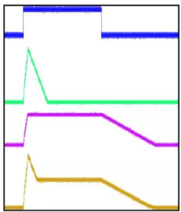
Abstract line chart with four colored lines (green, magenta, yellow, blue) showing step-like changes without any text or symbolsFigure 10: ADSR (orange) formed from components: AR (green) and ASR (magenta). Blue is gate input.
The way this patch works is illustrated in Figure 10. The blue trace is the input gate which triggers Channel A (green) to make an AR envelope, and Channel B (magenta) to make an ASR envelope. The ASR envelope is attenuated more than the AR envelope (due to Channel B's Level knob being lower than Channel A's). When these two envelopes are mixed together via an analog OR operation, the result is an ADSR envelope. The rise and fall of the AR envelope set the A and D segments; the sustain and fall of the ASR envelope set the S and R segments.
Table of Envelope Shapes
Figure 11 shows the output on the ENV jack and the color of the Shape light as the Shape slider is moved from left to right.
Figure 12 shows the output of the ENV jack when EOR is patched into Shape CV on Channel A. The Shape slider sets the rise curve, and the Shape knob sets the fall curve.

Figure 11: Waveshapes and colors produced at various Shape slider positions.

Figure 12: Waveshapes with different rise and fall shapes produced by patching EOR into Shape CV (Channel A).
Using Offset and Level Knobs
The Level and Offset knobs control the amplitude and DC level of the signal on the ENV output jacks. They do not affect the VCA or the audio signal (unless you patch ENV to VCA CV). Being independent of the VCA allows you to modulate something using an ENV output and control the modulation using Level and Offset, without disrupting the VCA.
The Level knob controls the amplitude of the envelope. When the knob is centered, no envelope will be output. Turning it to the right of center makes the envelope rise upward in voltage and fall downward (this is the most common setting for an envelope). If you turn Level left of center, the envelope will be inverted: it will rise downward and fall upward. The farther from center (in either direction) that you turn Level, the greater the amplitude. At fully clockwise or counter-clockwise, the amplitude will be about 10V.
The Offset knob shifts the envelope output up and down. With the Offset knob in the center, the envelope will rest at 0V and then rise to the voltage set by the Level knob (at most +10V if Level is fully clockwise, or -10V if Level is fully counter-clockwise). If Offset is turned left of center, the envelope will rest at a negative voltage. When Offset is fully counter-clockwise, it will rest at -10V. Going the other way, if Offset is turned to the right of center, the envelope will rest at a positive voltage, with +10V being the maximum.
The ENV output jacks clip at about -10V and +10V. Using Level and Offset at their extremes, you can easily cause clipping which results in a steady -10V or +10V output (and is not typically very interesting in a patch). If you're ever unsure where to set Level and Offset, a good starting place is to set Offset to the center, and Level to around 3:00 or higher.
RETRIG Jumper
The RETRIG jumper on the back of the module changes the Shaped Dual EnvVCA's behavior when it receives a trigger while an envelope is already running. When the jumper is not installed (factory default), triggers received as the envelope is rising will be ignored, and triggers received while the envelope is falling will make it begin rising again from its current voltage.
When the jumper is installed, the Shaped Dual EnvVCA will immediately restart the envelope when it receives a trigger, regardless of whether the envelope is rising or falling. When this happens, the envelope will immediately fall to 0V and begin to rise again. This sharp transition to 0V can cause clicking when used with the audio VCA section.
See the Creating Envelopes section on page 16 for more details.


- Shaped Dual EnvVCA
• 20HP Eurorack format module
- 0.95" (24mm) maximum depth (includes power cable)
• 10-pin Eurorack power header
• Power consumption
• +12V: 255mA max
-12V: 230mA max
- Audio/VCA
• 100k input impedance, 1k output impedance, DC-coupled
• VCA gain range: -75dB to +1.0dB, linear response to CV
• VCA unity gain @ 4.4V CV
• Frequency Response: DC to 20kHz, +/-0.1dB
- Envelope Times
• Minimum rise or fall time: \~200 s per segment
• Maximum rise or fall time: > 15 minutes (typically > 30 minutes) per segment
- Jacks:
• Env jack: Min = -10.2V, Max = 10.1V
• Envelope: Max amplitude = 9.3Vpp
- Trigger jack: rising edge threshold = 1.25V
• Follow jack: active range = 0V to +5V
- EO* jacks
• EOR (channel A): <80mV low to >4.50V high gate output
• EOF (channel B): <80mV low to >4.95V high gate output
• Audio In/Out jacks: <-10.2V to >+10.8V maximum range without clipping
- Shaped Dual EnvVCA features:
- Table of Contents
- Setting up your Shaped Dual EnvVCA
- Controls and Jacks
- Cycle Buttons
- Rise/Fall Sliders and Switches
- Time CV Jack and Rise/Fall CV Knobs
- Shape Sliders and Lights
- Shape Jack and Shape Knob
- ENV, Lin 5v, and OR Jacks
- Env. Level and Offset Knobs
- Audio In, Audio Out, and VCA CV Jacks
- Trig Jacks and Switches (Cycle, AR, ASR)
- Follow Jack
- EOR and EOF Output Jacks
- Making Notes (Basic)
- Making Notes in Stereo
- Synchronizing Channels: Making Notes Using Triggers
- Creating Stereo Motion
- Using a Keyboard or Sequencer
- Adding Chaos
- Modulating Waveshape
- Log Rise With Expo Fall
- Any Combination of Shapes
- Rapid Bursts
- Ratcheting
- Making an Oscillator
- Making a Kick Drum
- Self-patching ideas
- Frequency Modulation (FM)
- Chaotic FM
- Utility Patches
- Attenuator
- Trigger Delay With Pulse Width Control
- Inverted Trigger Delay (With Pulse Width Control)
- DC generator (Manual CV)
- Ducking (Sidechaining)
- Triggering With Switch Set To AR
- Triggering With Switch Set to ASR
- Triggering With RETRIG Jumper Off (Factory Default)
- Triggering With RETRIG Jumper On
- Cycle Button and Triggering With Switch Set To Cycle
- Follow Jack With Gates
- Fundamentals of the Follow Jack
- Audio Filter
- Waveshaper
- Portamento/Glide
- Sidechaining (Envelope Following)
- Using Non-Linear Shapes With Follow
- Creating ADSR Envelopes
- ADSR Envelope
- Table of Envelope Shapes
- Using Offset and Level Knobs
- RETRIG Jumper
- - Shaped Dual EnvVCA
- • Power consumption
- - Audio/VCA
- - Envelope Times
- - Jacks:
Brand : 4ms
Model : Dual EnvVCA
Category : Keyboard