
RBW-1500 - Uncategorized Royal Sovereign - Free user manual and instructions
Find the device manual for free RBW-1500 Royal Sovereign in PDF.


| Product Type | Banner Welder (RBW-1500) |
| Brand | Royal Sovereign |
| Welding Width | 0.6" (13-15 mm) |
| Stock Thickness Range | 0.2-0.8 mm (0.03") |
| Max. Pocket Width | 6" (150 mm) |
| Welding Speed | 0-5 m/min (16 ft/min) |
| Max. Heating Temperature | 662°F (350°C) |
| Power Consumption | 800 W |
| Input Voltage Options | 100-120V, 220V, 220-240V, 100V (50/60 Hz) |
| Cooling Method | Fan |
| Digital Display | LED |
| Unit Dimensions (L x W x H) | 24" x 15" x 9" (600 x 366 x 216 mm) |
| Unit Dimensions with Stand | 24" x 15" x 42" (600 x 366 x 1133 mm) |
| Net Weight | 106 lbs (48 kg) |
| Adjustable Stand Height | 29"-42" (735-1055 mm) |
| Safety Features | Emergency switch, automatic power-off after 5 min standby |
| Maintenance | Clean belts with scrap material; replace welding belts when worn |
| Warranty | 1 year parts and labor (original purchaser) |
| Included Accessories | Banner guide, feed tables (2), guide plate, adjustable stand, support bar, base, casters (4), leveling legs, tool box with bolts, welding belts, fuses |
| Repairability | Replaceable welding belts, fuses, and sensors; authorized service only |
Frequently Asked Questions - RBW-1500 Royal Sovereign
User questions about RBW-1500 Royal Sovereign
0 question about this device. Answer the ones you know or ask your own.
Ask a new question about this device
Download the instructions for your Uncategorized in PDF format for free! Find your manual RBW-1500 - Royal Sovereign and take your electronic device back in hand. On this page are published all the documents necessary for the use of your device. RBW-1500 by Royal Sovereign.
USER MANUAL RBW-1500 Royal Sovereign
natural_image
Exterior view of a RS dual scanning instrument with a white panel and black base (no visible text or symbols)Please read and retain these instructions.
To register your product, please go to www.royalsovereign.com USA.
Click the Customer Support Tab then Registration Tab.
www.royalsovereign.com
Royal Sovereign International, Inc.
CONTENTS
- INTRODUCTION 3
- SAFETY PRECAUTIONS 3
- PRODUCT IDENTIFICATION 5
- INSTALLATION 6
4.1 Electrical requirements 6
4.2 Box contents 6
4.3 Assembly 8
- Control Panel 9
- OPERATION 10
- MAINTENANCE 11
- TROUBLESHOOTING 14
- SPECIFICATION 15
- RECOMMENDED SETTING 15
- WARRANTY 16
1. INTRODUCTION
Thank you for choosing a Royal Sovereign RBW -1500. It has been designed and manufactured to provide years of continuous service. For complete operating and maintenance information please read this manual thoroughly. Upon receipt of your Banner Welder, please inspect the box, the machine and all other contents for shipping damage. Damage should be brought to the immediate attention of the delivering carrier (See page 6 for list of shipment elements).
2. SAFETY PRECAUTIONS
Failure to comply with any of the following safety procedures could result in serious injury. Please read all instructions carefully and keep for future reference. Royal Sovereign International Inc. cannot be held responsible for any damages to people, animals or objects due to noncompliance with the safety norms and recommendations of these documents.
- Only a licensed electrician should install wiring and outlet for the Banner Welder.
- Ensure the unit is plugged into a properly grounded outlet with the correct voltage.
- During operation, keep hands away from heating blocks and avoid inserting foreign objects into the machine.
- Keep flammable and wet objects away from the machine.
- Place machine on a level surface.
- Avoid excessive sunlight, humidity and extreme temperatures.
- Ensure the unit is turned off and unplugged from the outlet prior to moving and/or repairing.
- Keep out of reach of children.
- Only Royal Sovereign authorized maintenance and service technicians should make repairs.
- Do not attempt to weld items that exceed total recommended material thickness for the unit.
- Tampering with the protections and safety devices is dangerous for the people using the machine and for those exposed to it. Royal Sovereign International Inc. cannot be held responsible for any damages to people, animals or objects due to tampering with the protections.
- Pay attention to the danger notices on the Banner Welder.
Dangerous areas and residual risks
To avoid the risk of injury or health problems avoid all moving parts.
Pay attention to hands when operating the Banner Welder.
During certain intervention procedures on the machine, which are pointed out each time in this manual, residual risks for the operator may arise. Residual risks can be avoided by carefully complying with the procedures of this manual and using the personal protection devices indicated. such as:
- Carefully positioning the power cord so that it cannot be stepped on or damaged.
- Maintenance and service operations must be carried out only by the engineers authorized by the manufacturer.
- Pay attention to the danger notices on the Banner Welder.
Banner Welder should only be operated by trained personnel
DO NOT PLACE HANDS NEAR THE HOT ZONE!
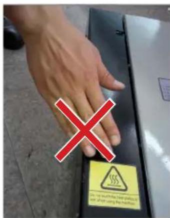
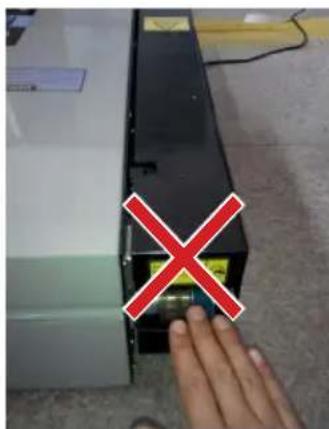
3. PRODUCT IDENTIFICATION
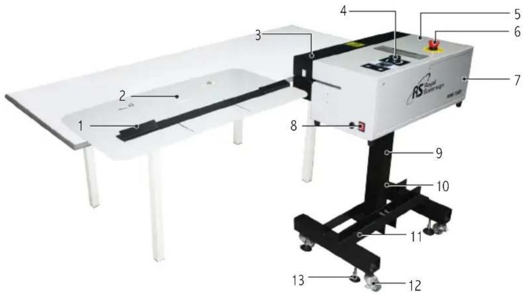
| NO PART NAME NO PART NAME | ||
| 1 Guide Plate 8 Main Switch | ||
| 2 Feed Table 9 Adjustable Stand | ||
| 3 Top Cover 10 Support Bar | ||
| 4 Speed Knob 11 Base | ||
| 5 Body 12 Caster | ||
| 6 Emergency Switch 13 Leveling Legs | ||
| 7 Rear Cover |
4. INSTALLATION
Note: The Banner Welder should be installed and assembled by a trained service technician
The Banner Welder should only be used in an area with the following characteristics:
• Protection from atmospheric agents.
• Proper illumination.
• Normal ambient operating conditions.
4.1 Electrical requirements
Royal Sovereign recommends that licensed electrician ensures proper power installation to your Banner Welder in accordance with electrical codes in your area.
4.2 Box contents
Thoroughly inspect the parts and the unit. It is imperative that any missing parts are reported and a claim is filed with the reseller immediately upon receipt of shipment.
| Part name Quantity Picture | |||
| Main box | Banner Welder Body 1 |  | |
| Banner Guide 1 | 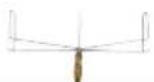 | ||
| Feed Table 1 1 | 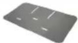 | ||
| Feed Table 2 1 | 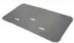 | ||
| Guide Plate 1 |  | ||
| Adjustable Stand 1 |  | ||
| Support Bar 1 | 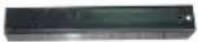 | ||
| Base 1 | 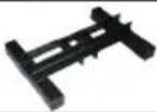 | ||
| Caster 4 |  | ||
| Foot 4 |  | ||
| Tube stopper inside 4 |  | ||
| Tool box | 5/16 Hexa Head Bolt Screw (M8*80)Star Washer (∅8.2) | 33 | 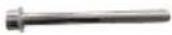 |
| Knob-Bolt Guide 2 |  | ||
| 5/16 Hexa Head Bolt Screw (M8*30)Spring Washer (∅8.2) | 44 | 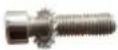 | |
| Welding Belt 4 |  | ||
| Wood ScrewWasher Plain | 66 | 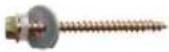 | |
| Fuse (AC250V 10A Lanbao)(100-120V) | 1 | 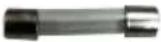 | |
| Fuse (AC250V 6.3A Lanbao)(220-240V) | 1 | 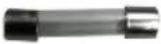 | |
| Fuse (AC250V 4A 5*20) 2 | 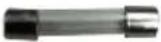 |
4.3 Assembly
- Open the box carton and remove all parts.
- Open the tool-box.
- Attach the caster to the base.(Fig. 4-1)
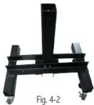
- Attach the support bar to the base using the supplied screws (M8x80).(Fig. 4-2)
natural_image
Mechanical support structure labeled Fig. 4-2, showing a black frame with vertical supports and two wheels (no text or symbols on the structure itself)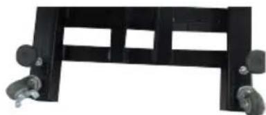
natural_image
Black metal frame with wheels and rectangular cutouts (no text or symbols visible)Fig. 4-1
natural_image
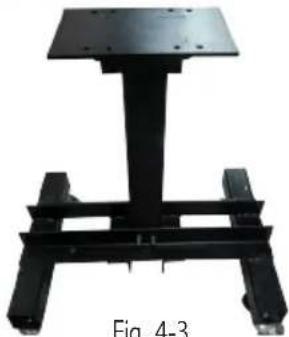
Mechanical support structure with a black frame and two vertical supports (no text or symbols visible)Fig. 4-3
- Attach the adjustable stand to the support bar with a suitable height using the supplied screws (M8x80).(Fig. 4-3)
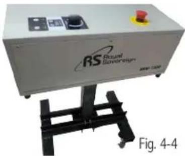
- Place the Banner Welder body on the adjustable stand and secure it with the supplied screws(M8x30).
Adjusting the leveling legs to keep it level and solid.(Fig. 4-4)
natural_image
Exterior view of a RS Roquel Saveraging industrial machine (no signage or text on the device itself)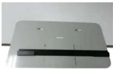
natural_image
Exterior view of a modern office building (no signage)Fig. 4-5
-
Attach the guide plate to the feed table using the KNOB-BOLT GUIDE. And then fasten the feed table to the work table (Note: work table is not supplied by manufacturer) using the supplied screws.(Fig. 4-5) Attach the second feed table as needed.
-
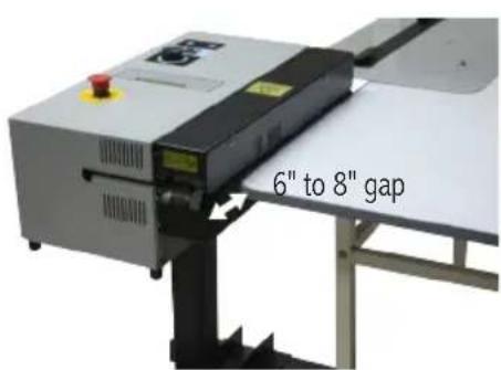
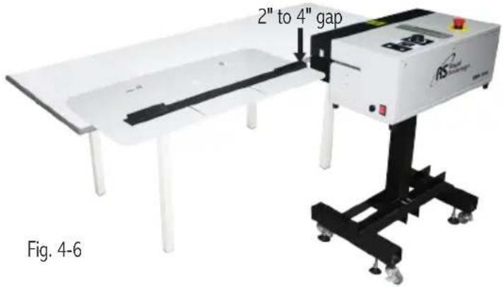
The machine is now ready for Operation(Fig. 4-6). Note the recommended component spacing.
5. CONTROL PANEL
- Speed: To adjust the speed of the welding belt, turn the speed knob clockwise to increase speed or counter-clockwise to decrease the speed.
- Temperature: To change the temperature use the up arrow to increase temperature or the down arrow to decrease temperature.
- ST/BY: To switch to stand-by mode (temperature will be automatically set to 176°F) press the ST/BY button.
If the machine is in Stand by Mode and no activity is made for 5 minutes the machine will automatically power off.
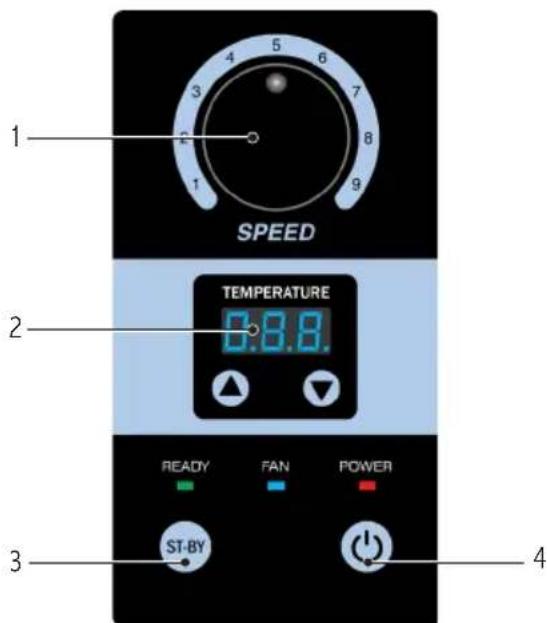
- Power: Power button will power the belts and heater on/off.
(Note: To completely power the unit on/off, toggle the main switch located near the power cord)
6. OPERATION
The Banner Welder must only be used by trained and qualified personnel.
The Banner Welder must be used only for welding material for which it has been designed.
For recommended maximum welding thickness see page 15.
Welding:
NOTE: When you feed the banner into the machine, you should guide the banner by the hand or by Banner Guide to keep it move in a straight line.
- The Banner Welder should be positioned on a level surface in an area with adequate lighting and enough work space for feeding materials. Connect the power cord to the AC outlet and turn the Power Switch to the on position. Depress
the power button on the control panel. The machine should only be operated from the front (control side) of the machine.
-
Before welding, first determine the folded area to be welded, adjust the guide plate and set it to the proper position. Set the temperature and speed referencing the Recommended Temperature and Speed section. (Note: Due to varying manufacturing processes of banner material fine tuning may be required).
-
Fold over material to allow for a minimum of 1/2" weld.
-
The point of the arrow is the middle of the weld. Align the outer edge of the fold over to the inner edge of the arrow.(Fig. 6-1)
-
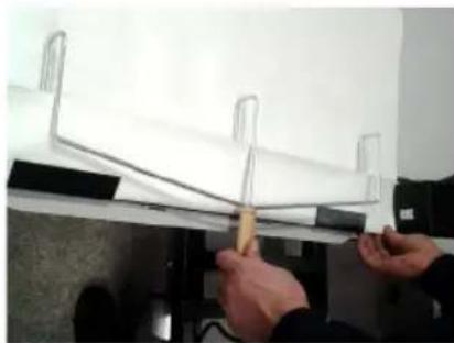
Guide the banner into machine. The drive belts will grab banner and pull the banner through machine.(Fig. 6-2)
-
Welded banner will exit machine.
-
Test the weld for tight seal.
-
For best results rotate the banner 90^ in a clock wise direction. Fold over the short side and guide the banner into the machine with the 4 layer fold entering last. (Note: Turn the speed down 1 to 2 positions to compensate for the extra layers of material).
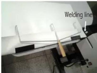
Fig. 6-1
natural_image
Close-up of hands holding a tool over a white sheet with metal clips, no visible text or symbolsFig. 6-2
- Turn the speed back up and rotate the banner again and fold the longer side of the banner and guide the banner into the machine with the 4 layer fold entering last.
(Note: Turn the speed back down 1 to 2 positions to compensate for the extra layers of material). - Turn and weld last end of banner. (Turning the speed down accounting for the extra layers of material).
Pole Pockets:
- Weld all unpocketed sides first. (If you weld pockets before regular sides, your pockets will be sealed closed).
- Loosen the Knob-Bolt Guide on the guide plate on the bottom of the table. Slide guide out to desired depth of pocket. Tighten the knobs on the guide plate
- Weld pocket at slower speed than regular weld side.
Rope Pockets:
- Weld banner the same as with pole pockets only making a smaller rope pocket.
- Insert an electrician's fish tape through pocket and hook on end of rope using a large paper clip. Pull rope through pocket.
Joining Two Pieces Togeather:
- Cut two pieces to size.
- Weld one outside edge on each piece.
- Lay the two pieces together FACE to FACE.
- Run through machine welding center seam.
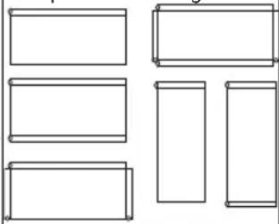
Sample Pocket Configurations
natural_image
Pure geometric shapes with no text, numbers, or symbols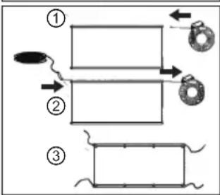
flowchart
graph TD
    A["Step ①"] --> B["Step ②"]
    B --> C["Step ③"]
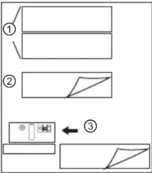
flowchart
graph TD
    A["Step ①"] --> B["Step ②"]
    B --> C["Step ③"]
    C --> D["Step ③"]
7. MAINTENANCE
The banner welding machine has all sealed bearings which do not need any additional lubrication. The only maintenance you may need to perform is replacing the worn out or ripped welding belts, or if you run a printed banner at too high heat, you may need to clean your welding belts.
This is a simple procedure you do while the machine is running.
- Run a piece of scrap material 2-3 times through the unit. This should clean belts sufficiently. If you need a more in depth cleaning go to step 2.
- Power the unit off and unplug the unit from the outlet. Once the unit has sufficiently cooled remove the top and bottom cover (as needed) and use a rubber sand belt cleaner to remove residual adhesive from the belts.
DON'T TRY TO REPLACE BELTS WHEN MACHINE IS HOT
Unplug the unit and allow it to sufficiently cool.
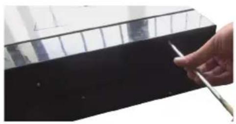
- Remove the top/board covers. Unscrew the Philips head screws on the top cover and bottom cover.(Fig. 7-1)
natural_image
Close-up of a hand holding a pen near a black rectangular object (no visible text or symbols)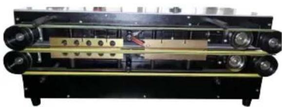
natural_image
Mechanical device with rollers and a central component, no visible text or symbolsFig. 7-1
- Remove the drive belt and the three wheels. Push the adjustable base and take off the worn out welding belts.(Fig. 7-2)
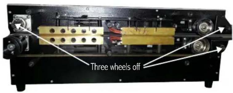
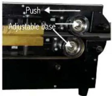
Fig. 7-2
- To increase or decrease tension on the heating blocks use the adjustment screw, one for the heating block and one for the cooling block.(Fig. 7-3)
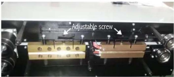
Fig. 7-3
- Replace the worn out belts with new belts.
- Loosen the adjustment screw. If the banner is too thick, please tight the adjustment screw.
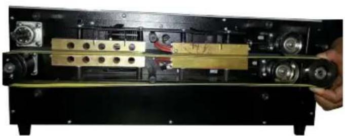
- Replace the drive belt and three wheels.(Fig. 7-4)
natural_image
Interior view of a device showing internal components and a hand holding the lid (no visible text or symbols)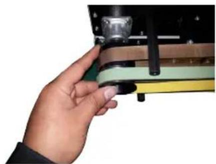
natural_image
Hand holding a mechanical component with a metallic cylindrical part inserted (no visible text or symbols)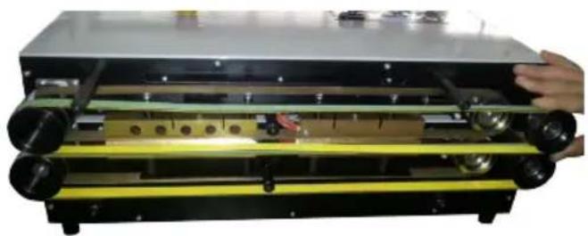
natural_image
Interior view of a mechanical device with yellow and black components, no visible text or symbolsFig. 7-4
- Adjust the upper and lower screws to ensure the belts run in the proper position.(Fig. 7-5)
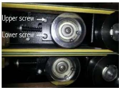
Fig. 7-5
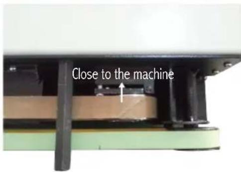
To move the belts closer to the machine loosen the upper screw and tighten the lower screw.
(To move the belts away from the machine tighten the upper screws and loosen the lower screw).
- Replace covers.
8. TROUBLE SHOOTING
| Symtom Cause Possible solution | ||
| Machine will not turn on | a. Power switch is in “off” position.b. Blown main power fuse. | a. Put the power switch to the “on “positionb. Replace the fuse |
| The display show “E0” The emergency switch is in “on” position Put the switch in “off” position | ||
| The display show “E1” | a. The wire of the upper sensor is abnormalb. The upper sensor is broken | a. Check the wireb. Replace the upper sensor |
| The display show “E2” | a. The wire of the lower sensor is abnormalb. The lower sensor is broken | a. Check the wireb. Replace the lower sensor |
| The display show “E3” The upper sensor is overheated Check the wire and pcb | ||
| The display show “E4” The lower sensor is overheated Check the wire and pcb | ||
9. SPECIFICATION
| Model Name RBW-1500 | |
| Input Voltage 220V(60Hz),220~240V(50Hz),100V(50/60Hz),110~120V(60Hz) | |
| Power Consumption 800W | |
| Welding Width 0.6" (13~15mm) | |
| Stock Thickness 0.03" (0.2mm-0.8mm) | |
| Max. Pocket Width 6" (150mm) | |
| Welding Speed 16 ft./min. (0-5m/min) | |
| Max. Heating Temperature 662°F(350°C) | |
| Adjustable stand 29"-42" (735 ~ 1055mm) | |
| Cooling Method Fan | |
| Digital Display LED | |
| Unit Dimensions 24" x 15" x 9" (600 x 366 x 216 mm) | |
| Unit Dimensions with Stand | 24" x 15" x 42" (600 x 366x 1133 mm) |
| Net Weight | 106 lbs. (48Kg) |
10. RECOMMENDED SETTING
| No | Media Thickness | Temperature | Speed |
| 1 | 10~13 OZ | 464~518°F (240~270°C) | 6~7 |
| 2 | 15 OZ | 482~536°F (250~280°C) | 5~6 |
| 3 | 18 OZ | 536~572°F (280~300°C) | 4~5 |
11. WARRANTY
Royal Sovereign International warrants the equipment sold is free from defects in material and workmanship for a period of One (1) year for Parts and Labor from the date of installation. This warranty is valid only to the original purchaser. This warranty is the only warranty made by Royal Sovereign International and cannot be modified or amended. Royal Sovereign's sole and exclusive liability and the customer's sole and exclusive remedy under this warranty shall be, at Royal Sovereign's option, to repair or replace any such defective part or product. These remedies are only available if Royal Sovereign's examination of the product discloses to Royal Sovereign's satisfaction that such defects actually exist and were not caused by misuse, neglect, attempt to repair, unauthorized alternation or modification, incorrect line voltage, fire, accident, flood or other hazard. All warranty claims must be filed through Royal Sovereign or the authorized Royal Sovereign dealer or reseller through which the equipment was originally purchased. Model, serial number and date of delivery are required for all claims.
The obligation to this warranty shall not extend to the following. The adjustment or replacement which are the normal responsibility of the owner. Example Welding Belts, loosened fasteners (bolts, screws etc.) Chipped paint or other items such as fuses that show wear under normal use. Normal operating adjustments to heat, speed or tension. Parts that are not manufactured by Royal Sovereign International Inc.
The warranty made herein is in lieu of all other warranties, expressed or implied, including any warranty or merchantability or fitness for a particular purpose. Royal Sovereign will not be liable for personal damage or personal injury (unless primarily caused by its negligence), loss of profit, or other incidental or consequential damages arising out of the use or inability to use this equipment.
ROYAL SOVEREIGN INTERNATIONAL, INC.
2 Volvo Drive Rockleigh, NJ 07647 USA
www.royalsovereign.com
RS INTERNATIONAL CANADA INC.
5610 Timberlea Blvd, Mississauga Ontario L4W 4M6 CANADA
TEL: +1) 905-461-1095 FAX: +1) 905-461-1096
TF: +1) 866 961-6673
www.royalsovereign.ca
- CONTENTS
- INTRODUCTION
- SAFETY PRECAUTIONS
- Dangerous areas and residual risks
- Banner Welder should only be operated by trained personnel
- PRODUCT IDENTIFICATION
- INSTALLATION
- Electrical requirements
- Box contents
- Assembly
- CONTROL PANEL
- OPERATION
- Welding:
- Pole Pockets:
- Rope Pockets:
- Joining Two Pieces Togeather:
- MAINTENANCE
- DON'T TRY TO REPLACE BELTS WHEN MACHINE IS HOT
- TROUBLE SHOOTING
- SPECIFICATION
- RECOMMENDED SETTING
- WARRANTY
Brand : Royal Sovereign
Model : RBW-1500
Category : Uncategorized