
Dual RP - Receiver ART - Free user manual and instructions
Find the device manual for free Dual RP ART in PDF.


| Product Type | Audio/Video Receiver |
| Brand | ART |
| Model | Dual RP |
| Dimensions (W x H x D) | 17.3 x 5.5 x 13.4 inches (440 x 140 x 340 mm) |
| Weight | 24.3 lbs (11 kg) |
| Power Supply | AC 120V, 60Hz |
| Power Consumption | 500W (standby: 0.5W) |
| Frequency Response | 20 Hz - 20 kHz (±0.5 dB) |
| Signal-to-Noise Ratio | 105 dB |
| Total Harmonic Distortion | 0.05% |
| Audio Inputs | 5x RCA, 2x Optical, 1x Coaxial |
| Audio Outputs | 2x RCA (Zone 2), 1x Subwoofer |
| Speaker Impedance | 4 - 16 ohms |
| Remote Control | Infrared (included) |
| Warranty | 1 year limited |
| Maintenance | Clean with dry cloth; avoid liquids |
| Safety | Class II, CE marked |
| Spare Parts Availability | Contact ART support for parts |
Frequently Asked Questions - Dual RP ART
User questions about Dual RP ART
0 question about this device. Answer the ones you know or ask your own.
Ask a new question about this device
Download the instructions for your Receiver in PDF format for free! Find your manual Dual RP - ART and take your electronic device back in hand. On this page are published all the documents necessary for the use of your device. Dual RP by ART.
USER MANUAL Dual RP ART
Phantom Powered Dual Remote Mic Preamp
ARTcessories

Service Manual

APPLIED RESEARCH AND TECHNOLOGY
IMPORTANT SAFETY INSTRUCTION – READ FIRST

This symbol, whenever it appears alerts you to the presence of uninsulated dangerous voltage inside the enclosure-voltage that may be sufficient to constitute a risk of shock.
This symbol, whenever it appears, alerts you to important operating and maintenance instructions in the accompanying literature. Please read the manual.
Read Instructions: Retain safety and operating instructions for future reference. Heed all warnings printed here and on the equipment. Follow the operating instructions printed in this user manual.
Do not open: There are no user serviceable parts inside. Refer any service work to qualified technical personnel only.
Environment: Protect from excessive dirt, dust, heat, and vibration when operating and storing. Avoid tobacco ash, drink spillage and smoke, especially that associated with smoke machines.
Handling: Protect the controls from damage during transit. Use adequate padding if you need to ship the unit. To avoid injury to yourself or damage to the equipment, take care when lifting, moving or carrying the unit.
Servicing: Refer servicing to qualified technical personnel.
Installation: Install the unit in accordance with the instructions printed in the user manual.
INTRODUCTION
Thank you for purchasing Applied Research and Technology's DUAL RP. The Dual RP is the ideal solution to increasing the performance of your ribbon and Dynamic microphones. This remotely powered preamp brings out all of the nuances of your mic before running into your recording interface or Mixer through long cable runs. With the Dual RP you can tailor the loading on the mic through the variable impedance controls.
The balanced output drives long cable runs with ease allowing you to place the preamp as close as possible to the mic before picking up any noise.
The Dual RP is packaged in a rugged extrusion with rubber feet for long, reliable operation.
Get the very best out of your mics with the Dual RP!
FEATURES
- Two very low noise mic preamps
• Variable Impedance controls - Low Cut filter single pole, 150Hz
- Adds at least 20dB of gain to your mic
- Runs off a Phantom power supply
- Able to drive long balanced cables
• Heavy duty extruded chassis - Designed and developed in the USA
INSTALLATION and OPERATION
Connect the outputs of the Dual RP to a Phantom powered source such as a mixer or preamplifier.
Connect the Dual RP inputs to your Ribbon or dynamic mics.
Make sure you start with the gain pots set to their minimum settings. Once connected engage the Phantom power and adjust the gain on the Dual RP for the desired level. The phantom power will not pass through to the inputs thus avoiding any potential damage to any dynamic or ribbon mics. As an added feature you have the ability to remove any unwanted wind noise or rumble by enabling the Low Cut filter per input.

flowchart
graph TD
    A["Audio Head"] -->|Connect Dynamic or Ribbon Mic's to the DUAL RP XLR inputs| B["DUAL RP XLR"]
    C["Microphone"] -->|Adjust the Impedance Controls For Mic1 and Mic2 to adjust the Tonal conture| B
    B -->|Connect to a mixer or preamp and then engage Phantom power| D["TUBE MIX"]
    D -->|Engage the Low Cut Filter Switches for Mic1 and Mic2| B
    B --> E["Output: 100 MHz"]
APPLICATIONS
Perfect for: getting the most out of your ribbon and dynamic mic!
The Dual RP may be used in a wide variety of applications and environments. Self-contained in an extruded enclosure, the remote mic Preamp is designed for continuous professional use. Because the unit is compact and lightweight, mounting location is not critical.
LOW CUT FILTER control
The Low Cut Filter is a single tuned High Pass Filter. The input signal can be filtered to remove low frequency information. The roll off frequency is set at 100Hz. Since it is single tuned, it preserves some low frequency content so its use is less obtrusive. It is especially useful in close mic'd applications cutting out pops and wind noise.
Variable Impedance Function
Using this variable impedance function allows the user to adjust the input impedance seen by the microphone, in turn getting a better tonal response from your microphone used.
Dynamic Mic
Dynamic (coil) microphones are sensitive to loading. If these mics are not coupled correctly, the result may be a loss in frequency response and could result in added distortion.
As an example a common mic like the SM57 prefers a 600 Ohm load. When the load is varied above or below the 600 Ohms, then the mid range resonance could sound harsh and distorted. The low-end response will also sound more controlled with a 600 Ohm load. There are many dynamic mics that may have similar issues but not be as sensitive to loading as the SM57.
Ribbon Mic
Ribbon type (transformer coupled) microphones are sensitive to the input impedance of the preamps or mixers used to achieve the optimum frequency response. A Ribbon mic would like to see an input impedance several times larger than its output impedance. Ribbon mics, being transformer coupled, have increased impedance at high and low frequencies. On the low end the mic is power bound, as you load it there becomes a low frequency cut off at higher levels, so it may sound distorted. At the high end, the output impedance of the transformer increases (independent of level), so the greater the load the less high end.
As an example, a typical ribbon mic with a characteristic impedance of 300 Ohms may have an inherent 600 Ohm impedance at 20kHz and a 2k impedance at its low frequency resonance (about 50Hz). If you set the input impedance to 10k Ohms your result would be a 0.25dB drop at 20kHz. This would also drop the low frequency resonance by 1.3dB. Compare this to a typical mixer input (3k input impedance) where you would get a 0.75dB drop at 20kHz and 3.6dB at resonance.
So increasing the input impedance seen by the mic using the impedance pots on the Dual RP will result in an optimum performance from the ribbon mic used. If the preamp or mixer input impedance is too low then you will start to limit the frequency response of the ribbon mic. When this occurs, the low-end of the microphone's sound quality will be limited and the transient response will sound flat degrading the overall performance of the microphone. So by adjusting the impedance pot on the Dual RP, you can achieve a clean full frequency response from your microphones using the Dual RP.
The beauty of the DRP and the RP-1 may be the ability to operate at higher impedance or control the impedance vs. the mixer ^1 you are currently using.
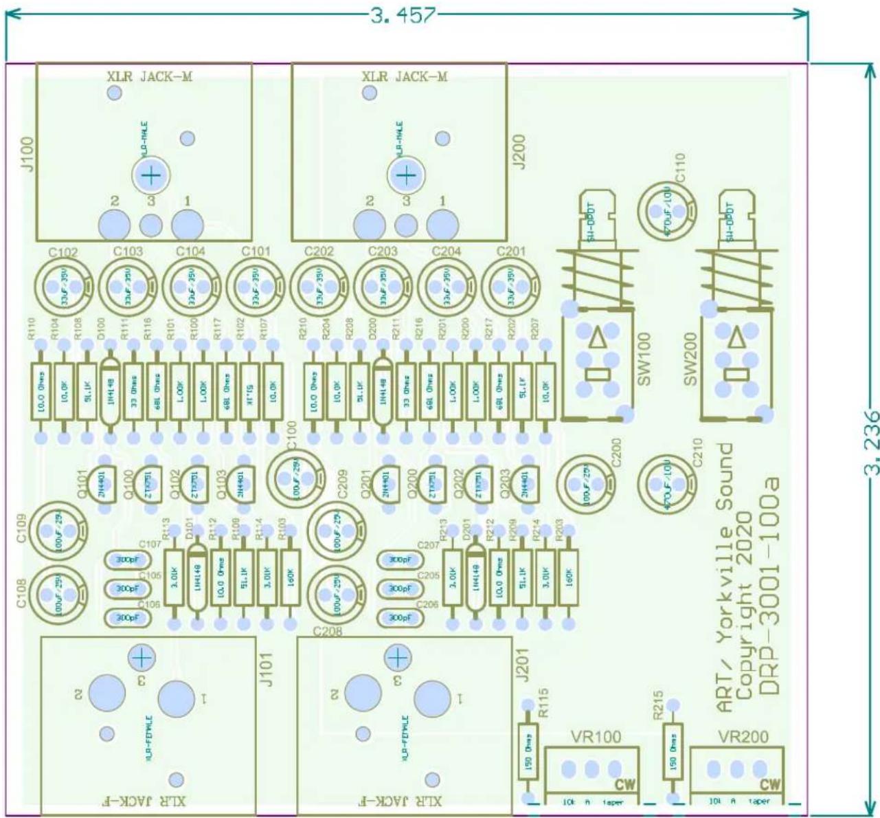
FULL BILL OF MATERIALS
| PART # | VALUE DES | CRIPTION PATTERN | QTY | LOCATION | |
| RESISTOR SECTION | |||||
| 1.00K Resistor, Metal Film, 0.1% AXIAL0.4 4 R100, R101, R200, R201 | |||||
| 10.0K Resistor, Metal Film, 0.1% AXIAL0.4 4 R104, R107, R204, R207 | |||||
| 3.01K Resistor, Metal Film, 0.1% AXIAL0.4 4 R113, R114, R213, R214 | |||||
| 681 Ohms Resistor, Metal Film, 0.1% AXIAL0.4 4 R116, R117, R216 | |||||
| 150 Ohms Resistor, Carbon Film, 5% AXIAL0.4 2 R115, R215 | |||||
| 160K Resistor, Carbon Film, 5% AXIAL0.4 2 R103, R203 | |||||
| 33 Ohms Resistor, Carbon Film, 5% AXIAL0.4 2 R111, R211 | |||||
| 10.0 Ohms Resistor, Carbon Film, 1% AXIAL0.4 4 R110, R112, R210, R212 | |||||
| 51.1K Resistor, Carbon Film, 1% AXIAL0.4 6 | R102, R108, R109, R202, R208, R209 | ||||
| POT/ SWITCH SECTION | |||||
| 1001025104 | 10k "A" taper | POT - Single Control / Trimmer | VR-16 | 2 | VR100, VR200 |
| 1005021101 | SW-DPDT | Switch, DPDT, PCB Mount | LC2255 | 2 | SW100, SW200 |
| CAPACITOR SECTION | |||||
| 300pF | Capacitor, Film / Ceramic | RADIAL0.1 | 6 | C105, C106, C107, C205, C206, C207 | |
| 100uF/25V | Capacitor, Electrolytic (polarized), Rubycon 25YXJ100MTA5X11 | LYTIC.1 | 6 | C100, C108, C109, C200, C208, C209 | |
| 33uF/35V | Capacitor, Electrolytic (polarized), Rubycon 25PK220MEFCTA6.3X11, | LYTIC.1 | 8 | C101, C102, C103, C104, C201, C202, C203, C204 | |
| 470uF/10V | Capacitor, Electrolytic (polarized), Rubycon 10YXG470MEFC6.3X11 | LYTIC.1 | 2 | C110, C210 | |
| JACKS AND CONNECTORS SECTION | |||||
| ARTC107 | XLR-FEMALE | XLR-Female Ref# Lih Sheng LX-1604H-3 | XLR-FEMALE | 2 | J101, J201 |
| ARTC108 | XLR-MALE | Jack, Canon XLR Male, 3-pin PCB Mount | XLR JACK-M | 2 | J100, J200 |
| DIODE AND TRANSISTOR SECTION | |||||
| ZTX751 | PNP Transistor - Single | TO92-EBC | 4 | Q100, Q102, Q200, Q202 | |
| 2N4401 | NPN Transistor - Single | TO92-EBC | 4 | Q101, Q103, Q201, Q203 | |
| 1N4148 | Diode - Signal or Power Rectifier | DIODE0.4 | 4 | D100, D101, D200, D201 | |
| PART # VALUE DESCRIPTION PATTERN QTY | LOCATION | ||||
| MECHANICAL SECTION | |||||
| DRP3001100a | PCB 1 | ||||
| 1662001100 | Extrusion Chassis 1 | ||||
| DRP2002100 | Front Panel 1 | ||||
| DRP2003100 | Rear Panel 1 | ||||
| 1662005100 | Rubber side caps 2 | ||||
| 2572004101 | Round Plastic KNOB, .54" dia. | Knobs for front panel pots | 2 | VR100, VR200 | |
| Gray switch cap | For front panel switches | 2 | SW100, SW200 | ||
| 1005032126 | FAS SCR #4 x3/8 PH FL HD ST BLK | Chassis screws | 4 | ||
| 1005032125 | PH,RD screw self tap for plastic | Screws for XLR jacks and tube bracket | 8 | JK1-JK4 | |
SERVICE PARTS
| ART PART # | VALUE | DESCRIPTION | PATTERN | QTY | LOCATION |
| 1001025104 | 10k "A" taper | POT - Single Control / Trimmer | VR-16 | 2 | VR100, VR200 |
| 1005021101 | SW-DPDT | Swt, PCB Mount Pushbutton Switch DPDT Standard Through Hole, Right Angle | LC2255 | 2 | SW100, SW200 |
| ARTC107 | XLR-FEMALE | XLR-Female Ref# Lih Sheng LX-1604H-3 | XLR-FEMALE | 2 | J101, J201 |
| ARTC108 | XLR-MALE | Jack, Canon XLR Male, 3-pin PCB Mount | XLR JACK-M | 2 | J100, J200 |
| DRP2002100 | Front Panel | 1 | |||
| DRP2003100 | Rear Panel | 1 | |||
| 1662005100 | Rubber side caps | 2 | |||
| 2572004101 | Round Plastic KNOB, .54" dia. | Knobs for front panel pots | 2 | VR100, VR200 | |
| 1005121102 | Black switch cap | Black switch cap rounded tip | For front panel switches | 2 | SW100, SW200 |
| Date: 4/16/2020 Sheet of | DRP-4001-100 a | 1 | 1 | |
| Fleet: C:\Products\..DRP-4001-100a.SchDoc | Drawn BY: m.m. | |||


- Material .062 Fiberglass Epoxy FR-4 or G-10
- 2 oz. Cu, 2 sides (.003 after plating, .001 min. in holes)
- Process = SMOBC, Hot Air Level Solder Plating (.0003 to .0015)
- Soldermask 2 sides, (Enthonne DSR-3241 or equ.)
- Silkscreen White, component side
- Warp and twist not to exceed .010 per inch

WARRANTY INFORMATION
Limited Warranty
Applied Research and Technology will provide warranty and service for this unit in accordance with the following warrants:
Applied Research and Technology, (A R T) warrants to the original purchaser that this product and the components thereof will be free from defects in workmanship and materials for a period of three years from the date of purchase. Applied Research and Technology will, without charge, repair or replace, at its option, defective product or component parts upon prepaid delivery to the factory service department or authorized service center, accompanied by proof of purchase date in the form of a valid sales receipt.
Online Registration
We recommend that you register your product online to insure prompt warranty repair servicing on any repair issues. Please go to www.artproaudio.com. Select "Support", then "Product Registration". Then input your information here.
Exclusions
This warranty does not apply in the event of misuse or abuse of the product or as a result of unauthorized alterations or repairs. This warranty is void if the serial number is altered, defaced, or removed.
A R T reserves the right to make changes in design or make additions to or improvements upon this product without any obligation to install the same on products previously manufactured.
A R T shall not be liable for any consequential damages, including without limitation damages resulting from loss of use. Some states do not allow limitations of incidental or consequential damages, so the above limitation or exclusion may not apply to you. This warranty gives you specific rights and you may have other rights, which vary from state to state.
For units purchased outside the United States, an authorized distributor of Applied Research and Technology will provide service
Fill in the following information for your reference:
Date of purchase ____
Purchased from ____
SERVICE
The following information is provided in the unlikely event that your unit requires service.
Be sure that the unit is the cause of the problem. Check to make sure the unit has power, all cables are connected correctly, and the cables themselves are in working condition. You may want to consult with your dealer for assistance in troubleshooting or testing your particular configuration.
If you believe that the ART unit is at fault, go to www.artproaudio.com.
Select "Support", then "Return Authorization Request" to request a return authorization number.
If you are returning the unit for service, pack the unit in its original carton or a reasonable substitute. The original packaging may not be suitable as a shipping carton, so consider putting the packaged unit in another box for shipping. Print the RA number clearly on the outside of the shipping box. Print your return shipping address on the outside of the box.
Include, with your unit, a note with the RA number and your contact information, including a return shipping address (we cannot ship to a P.O. box) and a daytime phone number, and a description of the problem, preferably attached to the top of the unit. Also include a copy of your purchase receipt.
SPECIFICATIONS
Input Connections 2 - XLR
Input Impedance 150 Ohms to 10k Ohms, variable
Max Input level -18dBu
Output Connections 2-XLR
Low Cut Filter Single pole, 100Hz
Max. Output Level +1dBm (600 Ohm Load)/+9dBu (10k load)
Gain 20dB @600 Ohms load, +27dB @ 10k load
THD < .002% @1kHz typ.
E.I.N. -129dBu "C" wtd.
C.M.R.R. >60dB 20-20kHz
Power Requirements External Power requirements
Standard 48V Phantom power supply.
Dimensions (HxWxD)
1.85-inch x 4.6-inch x 3.9-inch
(47mm x 117mm x 99mm)
Weight 0.71 lbs / 0.32 kg

APPLIED RESEARCH AND TECHNOLOGY
www.artproaudio.com
E-mail: support@artproaudio.com
© 2020 Applied Research & Technology / Yorkville Sound
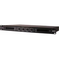

Brand : ART
Model : Dual RP
Category : Receiver