
DP-L2 - Processor TOA - Free user manual and instructions
Find the device manual for free DP-L2 TOA in PDF.


| Product Type | Digital Ambient Noise Controller (Audio Processor) |
| Dimensions (W x H x D) | 482 x 44 x 303 mm |
| Weight | 3.7 kg |
| Power Supply (CU Version) | 110–120 V AC, 50/60 Hz |
| Power Supply (CE Version) | 220–240 V AC, 50/60 Hz |
| Power Consumption (CU Version) | 20 W, 300 mA |
| Power Consumption (CE Version) | 20 W, 220 mA |
| Sampling Frequency | 48 kHz |
| Dynamic Range | Over 108 dB (IHF-A weighted) |
| Distortion | Under 0.006% at 1 kHz, +4 dB input/output (20–20,000 Hz BPF) |
| Frequency Response | 20–20,000 Hz (±1 dB) |
| A/D Converter | 24-bit |
| D/A Converter | 24-bit |
| Inputs | Sensor (ambient noise mic): +4/-48 dB, 10 kΩ, balanced; Input 1 & 2: +4/-8/-20 dB, 15 kΩ, balanced |
| Outputs | Monitor: +4 dB, 600 Ω, balanced; Output 1 & 2: +4 dB, 600 Ω, balanced |
| Key Functions | Automatic Level Control (ALC), Ambient Noise Control (ANC), Maximum Output Level control |
| Other Features | Phantom power (15 V DC) for sensor mic, ground lift switches, key lock, bypass at power off |
| Rack Mounting | 1U size (44.5 mm standard) |
| Operating Temperature | 0°C to 40°C |
| Operating Humidity | Under 90% RH (no condensation) |
| Cleaning Instructions | Use dry cloth; for heavy dirt, use cloth dampened with neutral cleanser; avoid benzene or thinner |
| Accessories Included | Power cord (2 m), 5x 3-pin removable terminal plugs, 1x 4-pin removable terminal plug |
Frequently Asked Questions - DP-L2 TOA
User questions about DP-L2 TOA
0 question about this device. Answer the ones you know or ask your own.
Ask a new question about this device
Download the instructions for your Processor in PDF format for free! Find your manual DP-L2 - TOA and take your electronic device back in hand. On this page are published all the documents necessary for the use of your device. DP-L2 by TOA.
USER MANUAL DP-L2 TOA
natural_image
Line drawing of a server rack unit with ports and connectors (no text or symbols)Thank you for purchasing TOA's Digital Ambient Noise Controller. Please carefully follow the instructions in this manual to ensure long, trouble-free use of your equipment.
TABLE OF CONTENTS
- SAFETY PRECAUTIONS .... 3
- GENERAL DESCRIPTION .... 5
- FEATURES .... 5
- HANDLING PRECAUTIONS .... 5
- NOMENCLATURE AND FUNCTIONS
Front 6
Rear 7
- SETTINGS
6.1. Setting Operations and Setting Screens
6.1.1. Keys and knobs used in settings 8
6.1.2. On-screen indications 9
6.2. Setting Flow Charts
6.2.1. System setting flow chart 10
6.2.2.ALC function setting flow chart 11
6.2.3. ANC function setting flow chart 12
6.2.4. ALC and ANC functions ON/OFF settings 13
6.2.5. INPUT LEVEL, OUTPUT LEVEL, and ALC LEVEL indication selection .... 14
6.3. Setting Procedures 15
6.4. Key Lock Function Settings
6.4.1. Locking the keys 21
6.4.2. Releasing the locked state 21
6.5. Restoring Default Settings 22
- CONNECTIONS
7.1. Removable Terminal Plug Connection 23
7.2. Example 1: Input and Output Connections
(When Connecting to a Stereo Mixer's Outputs) ...... 24
7.3. Example 2: Input and Output Connections
(When Connecting to a BGM Player's Outputs)....24
- RACK MOUNTING 25
- BLOCK DIAGRAM 26
- RECORDING TABLE OF FUNCTION SETTINGS 27
- SPECIFICATIONS ...... 28
Accessories 28
1. SAFETY PRECAUTIONS
- Before installation or use, be sure to carefully read all the instructions in this section for correct and safe operation.
- Be sure to follow all the precautionary instructions in this section, which contain important warnings and/or cautions regarding safety.
• After reading, keep this manual handy for future reference.
Safety Symbol and Message Conventions
Safety symbols and messages described below are used in this manual to prevent bodily injury and property damage which could result from mishandling. Before operating your product, read this manual first and understand the safety symbols and messages so you are thoroughly aware of the potential safety hazards.

WARNING
Indicates a potentially hazardous situation which, if mishandled, could result in death or serious personal injury.
When Installing the Unit
- Do not expose the unit to rain or an environment where it may be splashed by water or other liquids, as doing so may result in fire or electric shock.
- Use the unit only with the voltage specified on the unit. Using a voltage higher than that which is specified may result in fire or electric shock.
- Do not cut, kink, otherwise damage nor modify the power supply cord. In addition, avoid using the power cord in close proximity to heaters, and never place heavy objects -- including the unit itself -- on the power cord, as doing so may result in fire or electric shock.
- Since the unit is designed for in-door use, do not install it outdoors. When it gets wet with rain, there is a danger of electric shock.
- Do not touch a plug during thunder and lightning, as this may result in electric shock.
When the Unit is in Use
- To prevent a fire or electric shock, never open nor remove the unit case as there are high voltage components inside the unit. Refer all servicing to your nearest TOA dealer.
- Should the following irregularity be found during use, immediately switch off the power, disconnect the power supply plug from the AC outlet and contact your nearest TOA dealer. Make no further attempt to operate the unit in this condition as this may cause fire or electric shock.
- If you detect smoke or a strange smell coming from the unit.
- If water or any metallic object gets into the unit
- If the unit falls, or the unit case breaks
- If the power supply cord is damaged (exposure of the core, disconnection, etc.)
-
If it is malfunctioning (no tone sounds.)
-
Do not place cups, bowls, or other containers of liquid or metallic objects on top of the unit. If they accidentally spill into the unit, this may cause a fire or electric shock.
- Do not insert nor drop metallic objects or flammable materials in the ventilation slots on the unit's sides and rear, as this may result in fire or electric shock.

CAUTION
Indicates a potentially hazardous situation which, if mishandled, could result in moderate or minor personal injury, and/or property damage.
When Installing the Unit
- Never plug in nor remove the power supply plug with wet hands, as doing so may cause electric shock.
- When unplugging the power supply cord, be sure to grasp the power supply plug; never pull on the cord itself. Operating the unit with a damaged power supply cord may cause a fire or electric shock.
- When moving the unit, be sure to remove its power supply cord from the wall outlet. Moving the unit with the power cord connected to the outlet may cause damage to the power cord, resulting in fire or electric shock. When removing the power cord, be sure to hold its plug to pull.
- Do not block the ventilation slots on the unit's sides and rear. Doing so may cause heat to build up inside the unit and result in fire.
- Avoid installing the unit in humid or dusty locations, in locations exposed to the direct sunlight, near the heaters, or in locations generating sooty smoke or steam as doing otherwise may result in fire or electric shock.
- Be sure to follow the instructions below when rack-mounting the unit. Failure to do so may cause a fire or personal injury.
- Install the equipment rack on a stable, hard floor. Fix it with anchor bolts or take other arrangements to prevent it from falling down.
- When connecting the unit's power cord to an AC outlet, use the AC outlet with current capacity allowable to the unit.
- The socket-outlet shall be installed near the equipment and the plug shall be easily accessible.
When the Unit is in Use
- If dust accumulates on the power supply plug or in the wall AC outlet, a fire may result. Clean it periodically. In addition, insert the plug in the wall outlet securely.
- Switch off the power, and unplug the power supply plug from the AC outlet for safety purposes when cleaning or leaving the unit unused for 10 days or more. Doing otherwise may cause a fire or electric shock.
2. GENERAL DESCRIPTION
TOA's DP-L2 is a 1U size* rack-mountable digital audio processor having an ambient noise control (ANC) function which automatically adjusts output sounds in response to changes in ambient noise level. It also features an automatic level control (ALC) function that automatically adjusts the input signal level to an appropriate level.
*1U size: 44.5 mm (standard size)
3. FEATURES
- ANC function distinguishes between the unit's output sound and the ambient noise. (The unit's output sound is not detected as noise.)
- Various types of microphones, including ceiling flush mounted, dynamic and condenser types, usable for detecting ambient noise.
- Monitoring of sound collected via the ambient noise sensor microphone.
- Front-mounted LED meters for the input and output signal levels, and ALC and ANC levels.
- Easy setting of each function with the front-mounted LCD (liquid crystal display), keys and knobs.
4. HANDLING PRECAUTIONS
- The supplied power supply cord is designed for exclusive use with this unit. Never use it with other equipment.
- Install the unit in locations where the temperature is between 0 and +40^ and the moisture is less than 90% (no dew condensation must be formed).
- The DP-L2 is a precision audio component. To prevent failure, avoid locations where the unit may be exposed to strong shocks or vibrations.
- To clean, be sure to first switch off the unit's power, then wipe with a dry cloth. When the unit gets very dirty, use a cloth damped in a neutral cleanser. Never use benzene, thinner or chemically-treated cleaning cloth because such volatile liquids could deform or discolor the unit.
- FCC Rules (CU version) and Class A ITE (CE version) The CU version complies with Part 15 of the FCC Rules.
Note
This equipment has been tested and found to comply with the limits for a Class A digital device, pursuant to Part 15 of the FCC Rules. These limits are designed to provide reasonable protection against harmful interference when the equipment is operated in a commercial environment. This equipment generates, uses, and can radiate radio frequency energy and, if not installed and used in accordance with the instruction manual, may cause harmful interference to radio communications.
Operation of this equipment in a residential area is likely to cause harmful interference in which case the user will be required to correct the interference at his own expense.
Modifications
Any modifications made to this device that are not approved by TOA Corporation may void the authority granted to the user by the FCC to operate this equipment.
The CE version complies with Class A ITE.
Warning
This is a class A product. In a domestic environment this product may cause radio interference in which case the user may be required to take adequate measures.
5. NOMENCLATURE AND FUNCTIONS
[Front]
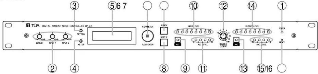
1. Power indicator
Lights when the power is switched on.
Tip: The power switch (17) is located on the rear panel.
2. Sensitivity controls
Adjust the input sensitivity for SENSOR input, INPUT 1, and INPUT 2.
Factory-setting: 0dB (center position).
3. SETTING key
Used to set each function. If this key is pressed, the setting screen is displayed on the LCD screen.
4. METER indication selector key
Indications of channels for which the signal level is displayed cycle through S (SENSOR level), 1 (Channel 1), and 2 (Channel 2) with each depression of this key. (See p. 14.)
5. Liquid crystal display
Pressing each function key displays the corresponding setting screen on this display.
If any key is not used for a specified period of time while the setting screen is displayed, the ALC and ANC levels are displayed.
6. PARAMETER/PUSH-ENTER knob
Rotate this knob to change parameters or select the setting contents on the setting screen.
(Such parameters and setting contents changed with this knob begin to work in real time.)
To save the current parameters, press this knob while the setting screen is displayed.
Note
If not saved, newly set parameters are cancelled when the power is switched off or the RESET key is pressed. Pressing this knob when the PUSH ENTER indication is displayed validates the on-screen setting item and saves the current parameters.
7. BACK key
Returns the setting item display to a previous screen.
8. NEXT key
Advances the setting item display to a next screen.
9. ALC key
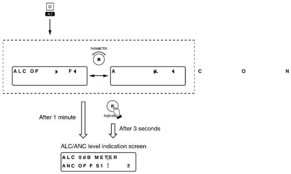
Permits the ALC function to be set to ON or OFF by means of the PARAMETER knob (6). If both this key and the SETTING key (3) are simultaneously pressed, settings for the ALC function can be performed.
10. INPUT LEVEL indicator
Indicates the input signal level of the channel selected with the METER indication selector key (4). (See p. 14.)
11. ALC LEVEL indicator
Indicates the amount of gain controlled by the ALC function.
12. MAXIMUM OUTPUT level control
Sets the maximum output level if rotated.
13. ANC key
Permits the ANC function to be set to ON or OFF by means of the PARAMETER knob (6). If both this key and the SETTING key (3) are simultaneously pressed, settings for the ANC function can be performed.
14. OUTPUT LEVEL indicator
Indicates the output signal level of the channel selected with the METER indication selector key (4). (See p. 14.)
15. ANC LEVEL indicator
Indicates the amount of gain controlled by the ANC function.
16. RESET key
Reactivates the unit.
Tip: Each set data stays stored, and is not erased.
[Rear]
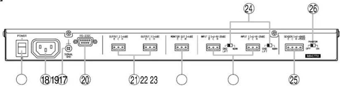
17. Power switch
Turns on and off the power.
Tip: The Power indicator (1) is located on the front panel.
18. AC inlet
Connect this inlet to the AC wall outlet using the supplied power cord.
19. Functional earth terminal
Hum noise may be generated when external equipment is connected to the unit. Connecting this terminal to the functional earth terminal of the external equipment may reduce the hum noise.
Note: This terminal is not for protective earth.
20. RS-232C Communication port (Non LPS)
Used for maintenance purposes, and not normally used.
21. OUTPUT 1 and 2 terminals (+4 dB\*, 600Ω)
Electronically-balanced outputs of removable terminal blocks. Polarity: E=Ground, C=Cold, H=Hot
Note: Be sure to use the supplied 3P removable terminal plugs for connection. (See p. 23.)
22. MONITOR OUT terminal (+4 dB\*, 600Ω)
Electronically-balanced output of removable terminal block. Polarity: E=Ground, C=Cold, H=Hot
Note: Be sure to use the supplied 3P removable terminal plug for connection. (See p. 23.)
23. INPUT 1 and 2 terminals
(+4/-8/-20 dB* changeable, 15 kΩ)
Electronically-balanced inputs of removable terminal blocks. Polarity: E=Ground, C=Cold, H=Hot
Note: Be sure to use the supplied 3P removable terminal plugs for connection. (See p. 23.)
24. Ground lift switches
When the unit is connected to external equipment, a ground may create a loop, potentially generating a hum noise. In such cases, the ground loop can be cut off by setting the corresponding switch to the LIFT position. Normally, set both switches to the NORM position.
25. SENSOR input terminal
(+4/-48 dB* changeable, 10 kΩ)
Electronically-balanced input of removable terminal block. Polarity: E=Ground, C=Cold, H=Hot
Power of 15 V DC/10 mA can be supplied from the rightmost "+15 V DC" pin terminal.
Note: Be sure to use the supplied 4P removable terminal plug for connection. (See p. 23.)
26. PHANTOM power switch
Turn on the switch when using a phantom-powered sensor microphone, and the phantom power of 15 V DC is supplied. Otherwise, when using other type of sensor microphone or other equipment, be sure to turn off the switch.
$$ ^ {*} 0 \mathrm{dB} = 0. 7 7 5 \mathrm{V} $$
6. SETTINGS
6.1. Setting Operations and Setting Screens
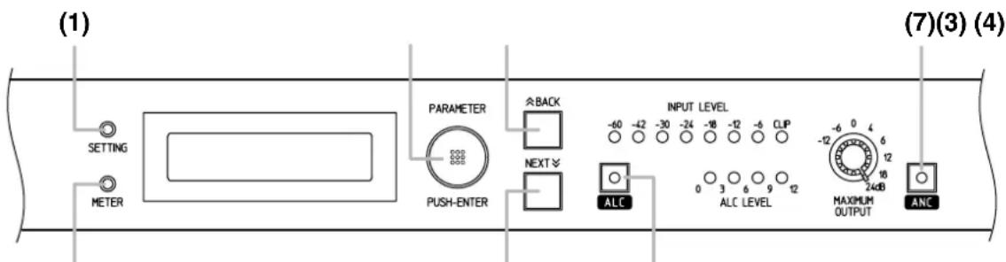
6.1.1. Keys and knobs used in settings
(2) (5) (6)
(1) SETTING Key
Permits the system setting screen to display. If this key is pressed simultaneously with the ALC key, the ALC setting screen is displayed. If pressed simultaneously with the ANC key, the ANC setting screen is displayed.
(2) METER Indication Selector Key
Selects the channel for which the signal level is indicated by the INPUT LEVEL, OUTPUT LEVEL and ALC LEVEL indicators. The on-screen indication cycles through S (SENSOR level), 1 (Channel 1), and 2 (Channel 2) as the key is pressed.
(3) PARAMETER/PUSH-ENTER Knob
Rotating this knob while [ ] is flashing in the setting screen permits either the setting content or parameter to be selected. (Such parameters and setting contents changed begin to work in real time.) Pressing this knob afterward permits [ ] display to disappear, saving the current parameters.
Pressing this knob when the PUSH ENTER indication is displayed validates the on-screen setting item and saves the current parameters.
(4) BACK Key
Returns the display to a previous screen.
(5) NEXT Key
Advances the display to a next screen.
(6) ALC Key
Permits the ALC function to be set to ON or OFF by rotating the PARAMETER knob. If this key is pressed simultaneously with the SETTING key, the ALC setting screen is displayed.
(7) ANC Key
Permits the ANC function to be set to ON or OFF by rotating the PARAMETER knob. If this key is pressed simultaneously with the SETTING key, the ANC setting screen is displayed.
6.1.2. On-screen indications
[ALC/ANC level indication screen]
Displayed when in normal operation state.
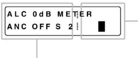
The signal level of the highlighted channel is displayed by the INPUT LEVEL, OUTPUT LEVEL, and ALC LEVEL indicators. The selected channel moves cyclically among S (SENSOR level), 1 (Channel 1), and 2 (Channel 2) as the Meter indication selector key is pressed.
Indicates ALC and ANC levels or their OFF states.
[Setting screen]
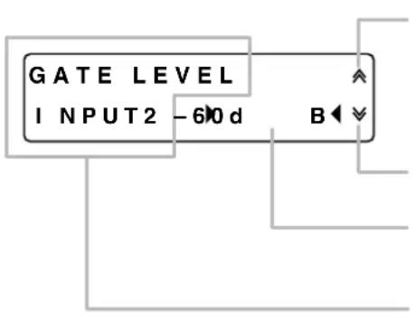
Appears when there is a previous screen.
Appears when there is a next screen.
Displays the setting content or value.
Varies as the PARAMETER knob is rotated.
Displays the setting items.
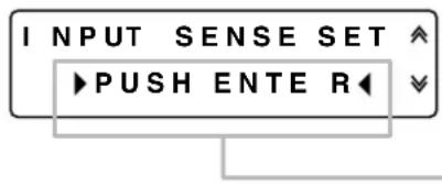
Press the PUSH-ENTER knob when this indication is displayed.
6.2. Setting Flow Charts
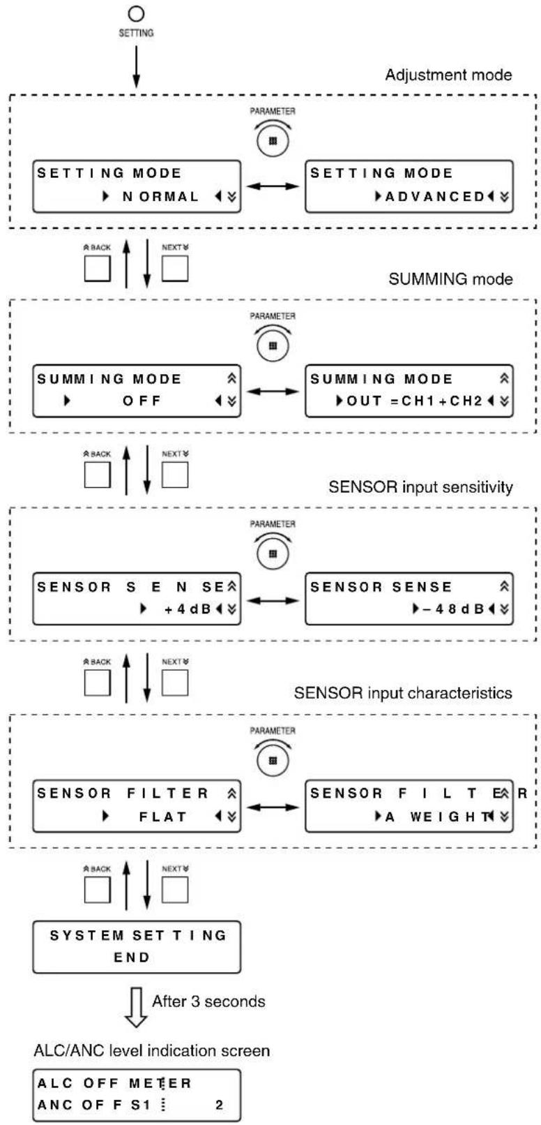
6.2.1. System setting flow chart
flowchart
graph TD
    A["SETTING"] --> B["adjustment mode"]
    B --> C["SETTING MODE ▶ NORMAL ◀"]
    C --> D["SETTING MODE ▶ ADVANCED ◀"]
    D --> E["SUMMING MODE"]
    E --> F["SUMMING MODE ▶ OFF ◀"]
    F --> G["SUMMING MODE ▶ OUT = CH1 + CH2 ◀"]
    G --> H["SENSOR input sensitivity"]
    H --> I["SENSOR S E N SE ▶ +4 dB ◀"]
    I --> J["SENSOR SENSE ▶ -48 dB ◀"]
    J --> K["SENSOR input characteristics"]
    K --> L["SENSOR FILTER ▶ FLAT ◀"]
    L --> M["SENSOR FILTER ▶ FLAT ◀"]
    M --> N["System SETTING END"]
    N --> O["After 3 seconds"]
    O --> P["ALC/ANC level indication screen"]
    P --> Q["ALC OFF METER ANC OF FS1 : : 2"]
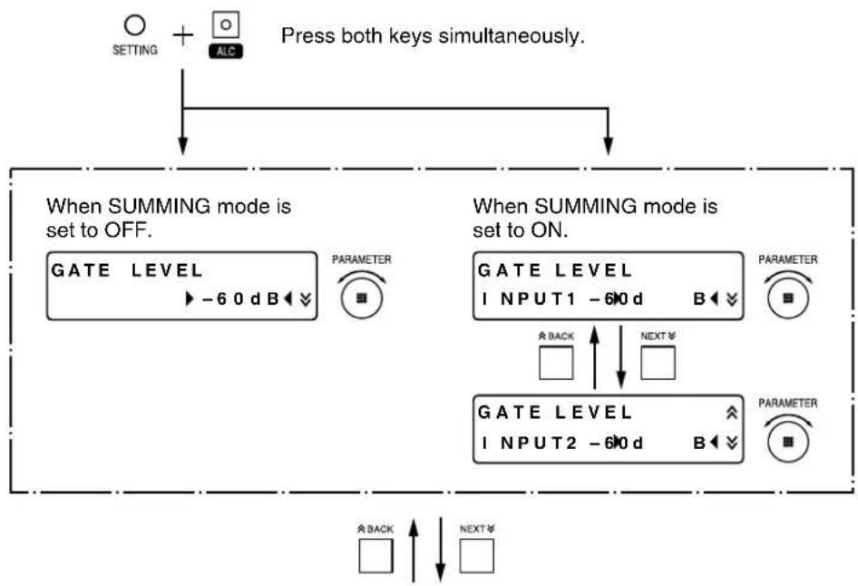
6.2.2. ALC function setting flow chart
flowchart
graph TD
    A["Setting + ALC"] --> B["Press both keys simultaneously."]
    B --> C{When SUMMING mode is set to OFF.}
    C --> D["GATE LEVEL -60 dB"]
    D --> E["PARAMETER"]
    E --> F["When SUMMING mode is set to ON."]
    F --> G["GATE LEVEL INPUT1 -60 d"]
    G --> H["PARAMETER"]
    H --> I["When SUMMING mode is set to ON."]
    I --> J["GATE LEVEL INPUT2 -60 d"]
    J --> K["PARAMETER"]
    K --> L["When SUMMING mode is set to ON."]
    L --> M["When SUMMING mode is set to OFF."]
    M --> N["PARAMETER"]
    N --> O["When SUMMING mode is set to ON."]
flowchart
graph TD
    A["When set to NORMAL mode."] --> B["INPUT SENSE SET ↑ PUSH ENTER ↓"]
    B --> C["↓"]
    C --> D["INPUT SENSE SET IN PROGRESS .."]
    D --> E["↓"]
    E --> F["INPUT SENSE SET COMPLETE"]
    G["When set to ADVANCED mode."] --> H["When SUMMING mode is set to OFF."]
    H --> I["PARAMETER"]
    I --> J["INPUT SENSE SET ↑ + 4 dB ↓"]
    J --> K["PARAMETER"]
    K --> L["↓"]
    L --> M["INPUT SENSE SET ↑ INPUT2 ↑ + 4 ↓"]
    M --> N["PARAMETER"]
    N --> O["↓"]
    O --> P["BACK ↑"]
    P --> Q["NEXT ↓"]
flowchart
graph TD
    A["After 3 seconds"] --> B["BGM LEVEL"]
    B --> C["PARAMETER"]
    C --> D["ALC SETTING END"]
    D --> E["After 3 seconds"]
    E --> F["ALC/ANC level indication screen"]
    F --> G["ALC 0 dB METER, ANC OFF S1 ... 2"]
    style A fill:#f9f,stroke:#333
    style B fill:#ccf,stroke:#333
    style C fill:#cfc,stroke:#333
    style D fill:#fcc,stroke:#333
    style E fill:#cff,stroke:#333
    style F fill:#ffc,stroke:#333
6.2.3. ANC function setting flow chart
flowchart
graph TD
    A["SETTING + ANC"] --> B["MIN NOISE SET<br>► PUSH ENTER"]
    B --> C["MIN NOISE SET<br>IN PROGRESS. ."]
    C --> D["MIN NOISE SET<br>COMPLETE"]
    D --> E["MAX LEVEL 0<br>MIN LEVEL -6"]
    E --> F["SAMPLE TIME<br>► 20 sec"]
    F --> G["GAIN RATIO<br>► N : S = 3 : 3"]
    G --> H["When set to ADVANCED mode."]
    H --> I["ANC SETTING<br>END"]
    I --> J["After 3 seconds"]
    J --> K["ALC/ANC level indication screen"]
    L["ADJ. ZERO S : +1<br>► 0 dB L: -1 8"] --> M["PARAMETER"]
    M --> N["SENSING POINT<br>f1 210.0Hz"]
    N --> O["PARAMETER"]
    O --> P["SENSING POINT<br>f2 550.0Hz"]
    P --> Q["PARAMETER"]
    Q --> R["SENSING POINT<br>f3 1.08 kHz"]
    R --> S["PARAMETER"]
6.2.4. ALC and ANC functions ON/OFF settings
[ALC function setting]
flowchart
graph TD
    A["ALC"] --> B["PARAMETER"]
    B --> C["ALC OF F"]
    C --> D["A"]
    D --> E["L"]
    E --> F["After 1 minute"]
    F --> G["ALC/ANC level indication screen"]
    G --> H["ALC 0 dB METER"]
    G --> I["ANC OFF S1 2"]
    H --> J["PUSH-EN"]
    I --> J
    J --> K["After 3 seconds"]
[ANC function setting]
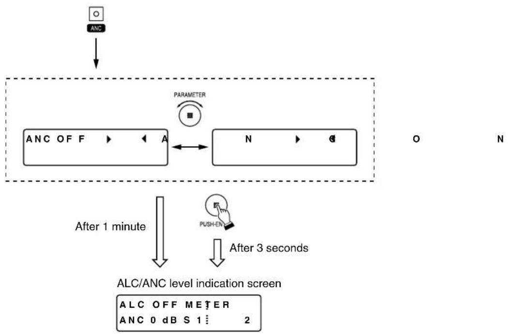
flowchart
graph TD
    A["ARC"] --> B["PARAMETER"]
    B --> C["ANCOFF"]
    C --> D["ALC/ANC level indication screen"]
    D --> E["PUSH-EN"]
    E --> F["After 1 minute"]
    F --> G["After 3 seconds"]
    G --> H["O"]
    G --> I["N"]
6.2.5. INPUT LEVEL, OUTPUT LEVEL, and ALC LEVEL indication selection
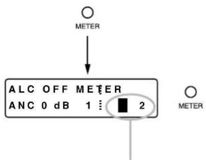
The cursor moves to the channels S, 1, 2, S, and so on for selection with each depression of the METER indication selector key.
[Level indicators and indicated channel table]
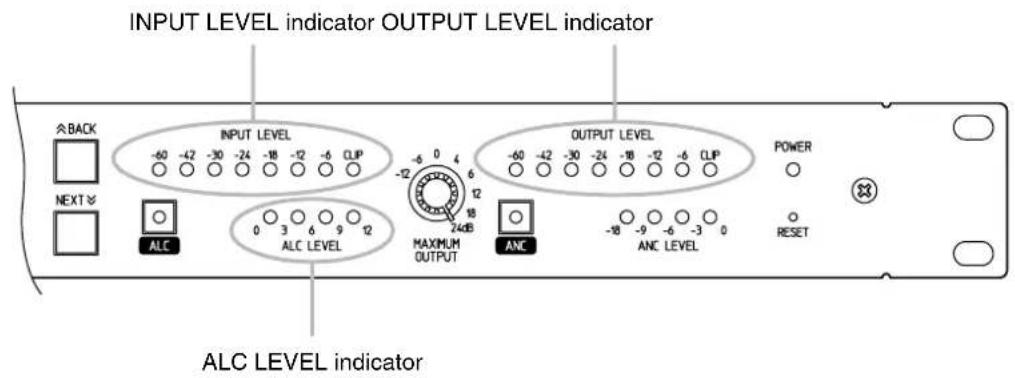
| Selected channel | Indicators | ||
| INPUT LEVEL indicator | ALC LEVEL indicator | OUTPUT LEVEL indicator | |
| S | SENSOR level | Channel 1 | MONITOR OUT level |
| 1 | Channel 1 level | Channel 1 | Channel 1 level |
| 2 | Channel 2 level | Channel 2 | Channel 2 level |
Note: The ANC performs the same operation on both Channels 1 and 2.
6.3. Setting Procedures
The general outlines of setting procedures are as shown at right. If there is a function that is not used, advance to the next procedure without setting such a function. Ensure that equipment connections are completed before performing each setting.
Note
Pressing the PUSH-ENTER knob during the setting saves the current parameters. (Even if the unit's power is switched off and on again, the set parameters are maintained.)
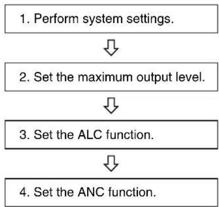
flowchart
graph TD
    A["Perform system settings."] --> B["Set the maximum output level."]
    B --> C["Set the ALC function."]
    C --> D["Set the ANC function."]
Step 1. Perform system settings.
Press the SETTING key to enter the system setting screen (adjustment mode), then select the setting item with the PARAMETER knob. (See p. 10; System setting flow chart.)
1-1. Set the adjustment mode.
Setting parameter: NORMAL or ADVANCED
The ADVANCED mode has more manually-operated setting items than the NORMAL mode, enabling fine settings.
1-2. Set the SUMMING mode.
Setting parameter: OFF or OUT = CH1+CH2
The diagrams below show the relationship between the input/output and the ALC/ANC functions when the SUMMING mode is ON (OUT = CH1+CH2) and that when the SUMMING mode is OFF.
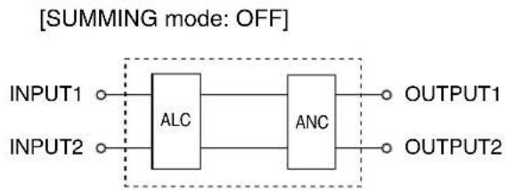
flowchart
graph LR
    INPUT1["INPUT1"] --> ALC["ALC"]
    INPUT2["INPUT2"] --> ALC
    ALC --> ANC["ANC"]
    ANC --> OUTPUT1["OUTPUT1"]
    ANC --> OUTPUT2["OUTPUT2"]
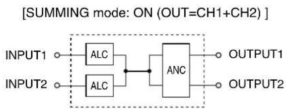
flowchart
graph LR
    INPUT1["INPUT1"] --> ALC1["ALC"]
    INPUT2["INPUT2"] --> ALC2["ALC"]
    ALC1 --> ANC["ANC"]
    ALC2 --> ANC
    ANC --> OUTPUT1["OUTPUT1"]
    ANC --> OUTPUT2["OUTPUT2"]
    style ALC1 fill:#f9f,stroke:#333
    style ALC2 fill:#f9f,stroke:#333
    style ANC fill:#ccf,stroke:#333
1-3. Set the SENSOR input sensitivity.
Setting parameter: +4 dB or -48 dB
1-4. Set the SENSOR input characteristics.
Setting parameter: FLAT or A WEIGHT (A-weighted filter)
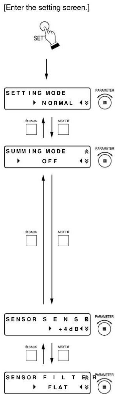
flowchart
graph TD
    A["SET"] --> B["SETTING MODE\n▶ NORMAL"]
    B --> C["BACK"]
    B --> D["NEXT"]
    C --> E["SUMMING MODE\n▶ OFF"]
    D --> E
    E --> F["BACK"]
    E --> G["NEXT"]
    F --> H["SENSOR S E N S\n▶ + 4 dB"]
    G --> H
    H --> I["BACK"]
    H --> J["NEXT"]
    I --> K["SENSOR FIL T E\n▶ FLAT"]
    J --> K
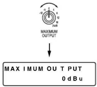
Step 2. Set the maximum output level.
Check the maximum input level of the equipment connected to the unit's OUTPUT 1 and OUTPUT 2, then adjust it to the appropriate level with the MAXIMUM OUTPUT level control.
Tip
Both the OUTPUT 1 and OUTPUT 2 are set to the same level.
Step 3. Set the ALC function.
The setting item differs depending on the adjustment mode (NORMAL or ADVANCED) and SUMMING mode (OFF or OUT=CH1+CH2).
To set, press both the SETTING key and the ALC key simultaneously to enter the setting screen, then select the setting value with the PARAMETER knob.
(See p. 11; ALC function setting flow chart.)
[Enter the setting screen.]
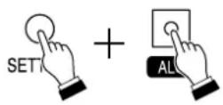
Press both keys simultaneously.
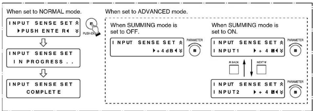
When the adjustment mode is set to NORMAL, and SUMMING mode to OFF:
Connect a sound source to INPUT 1.
When INPUT 2 is used in the setting step below, also connect a sound source to INPUT 2.
3-1. Set the GATE LEVEL while monitoring the INPUT LEVEL indicator.
Both the INPUT 1 and INPUT 2 are set to the same level.
When the input level is below the GATE LEVEL, the ALC level is kept unchanged.
When it is above the GATE LEVEL, the ALC function works to change the controlled variable.
3-2. Press the PUSH-ENTER knob.
Input sensitivity is automatically adjusted to +4, -8, or -20 dB depending on the input level.
Both the INPUT 1 and INPUT 2 are set to the same level.
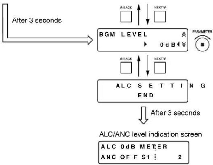
3-3. Adjust the BGM broadcast level.
Perform this step when the INPUT 1 is used for announcement and the INPUT 2 is for BGM, and when BGM is desired to be broadcast in smaller volume than announcement.
The BGM LEVEL to be set here is the attenuation level to the announcement level.
For example, when BGM is broadcast 6 dB smaller than announcement in volume, set the BGM LEVEL to -6 dB.
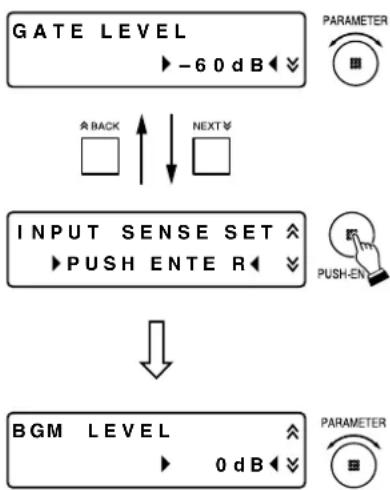
flowchart
graph TD
    A["GATE LEVEL"] --> B["PARAMETER"]
    B --> C["INPUT SENSE SET ↑ PUSH ENTER ↓"]
    C --> D["BGM LEVEL"]
    D --> E["PARAMETER"]
When the adjustment mode is set to NORMAL, and SUMMING mode to OUT = CH1+CH2:
Connect a sound source to INPUT 1.
When INPUT 2 is used in the setting step below, also connect a sound source to INPUT 2.
3-1. Set the GATE LEVEL of INPUT 1 while monitoring the INPUT LEVEL indicator.
When the input level is below the GATE LEVEL, the ALC level is kept unchanged.
When it is above the GATE LEVEL, the ALC function works to change the controlled variable.
3-2. Set the GATE LEVEL of INPUT 2 while monitoring the INPUT LEVEL indicator.
When the input level is below the GATE LEVEL, the ALC level is kept unchanged.
When it is above the GATE LEVEL, the ALC function works to change the controlled variable.
3-3. Press the PUSH-ENTER knob.
The sensitivity of INPUT 1 and INPUT 2 is automatically adjusted to +4, -8, or -20 dB depending on the input level.
3-4. Adjust the BGM broadcast level.
Perform this step when the INPUT 1 is used for announcement and the INPUT 2 is for BGM, and when BGM is desired to be broadcast in smaller volume than announcement.
The BGM LEVEL to be set here is the attenuation level to the announcement level.
For example, when BGM is broadcast 6 dB smaller than announcement in volume, set the BGM LEVEL to -6 dB.
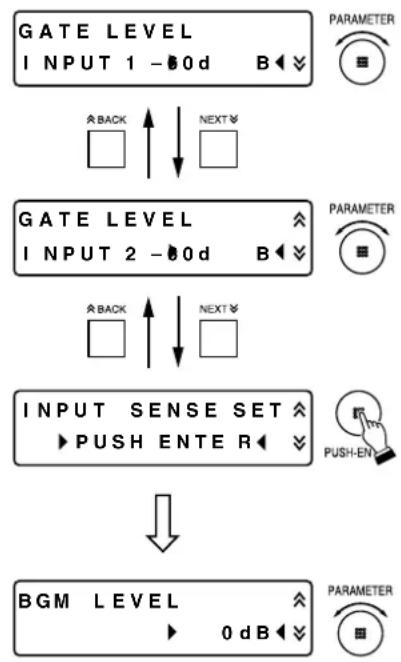
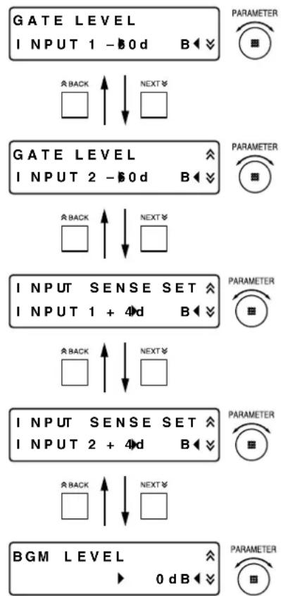
flowchart
graph TD
    A["GATE LEVEL INPUT 1 - 0d"] --> B["PARAMETER"]
    A --> C["BACK"]
    A --> D["NEXT"]
    E["GATE LEVEL INPUT 2 - 0d"] --> F["PARAMETER"]
    E --> G["BACK"]
    E --> H["NEXT"]
    I["INPUT SENSE SET PUSH ENTER"] --> J["PUSH-EN"]
    K["BGM LEVEL 0 dB"] --> L["PARAMETER"]
When the adjustment mode is set to ADVANCED, and SUMMING mode to OFF:
Connect a sound source to INPUT 1.
When INPUT 2 is used in the setting step below, also connect a sound source to INPUT 2.
3-1. Set the GATE LEVEL while monitoring the INPUT LEVEL indicator.
Both the INPUT 1 and INPUT 2 are set to the same level.
When the input level is below the GATE LEVEL, the ALC level is kept unchanged.
When it is above the GATE LEVEL, the ALC function works to change the controlled variable.
3-2. Set the input sensitivity to +4, -8, or -20 dB depending on the input level.
Both the INPUT 1 and INPUT 2 are set to the same level.
The input sensitivity is automatically set to
3-3. Adjust the BGM broadcast level.
Perform this step when the INPUT 1 is used for announcement and the INPUT 2 is for BGM, and when BGM is desired to be broadcast in smaller volume than announcement.
The BGM LEVEL to be set here is the attenuation level to the announcement level.
For example, when BGM is broadcast 6 dB smaller than announcement in volume, set the BGM LEVEL to -6 dB.
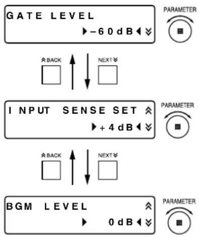
When the adjustment mode is set to ADVANCED, and SUMMING mode to OUT=CH1+CH2:
Connect a sound source to INPUT 1.
When INPUT 2 is used in the setting step below, also connect a sound source to INPUT 2.
3-1. Set the GATE LEVEL of INPUT 1 while monitoring the INPUT LEVEL indicator.
When the input level is below the GATE LEVEL, the ALC level is kept unchanged.
When it is above the GATE LEVEL, the ALC function works to change the controlled variable.
3-2. Set the GATE LEVEL of INPUT 2 while monitoring the INPUT LEVEL indicator.
When the input level is below the GATE LEVEL, the ALC level is kept unchanged.
When it is above the GATE LEVEL, the ALC function works to change the controlled variable.
3-3. Set the input sensitivity of INPUT 1 to +4, -8, or -20 dB depending on the input level.
3-4. Set the input sensitivity of INPUT 2 to +4, -8, or -20 dB depending on the input level.
3-5. Adjust the BGM broadcast level.
Perform this step when the INPUT 1 is used for announcement and the INPUT 2 is for BGM, and when BGM is desired to be broadcast in smaller volume than announcement.
The BGM LEVEL to be set here is the attenuation level to the announcement level.
For example, when BGM is broadcast 6 dB smaller than announcement in volume, set the BGM LEVEL to -6 dB.
Step 4. Set the ANC function.
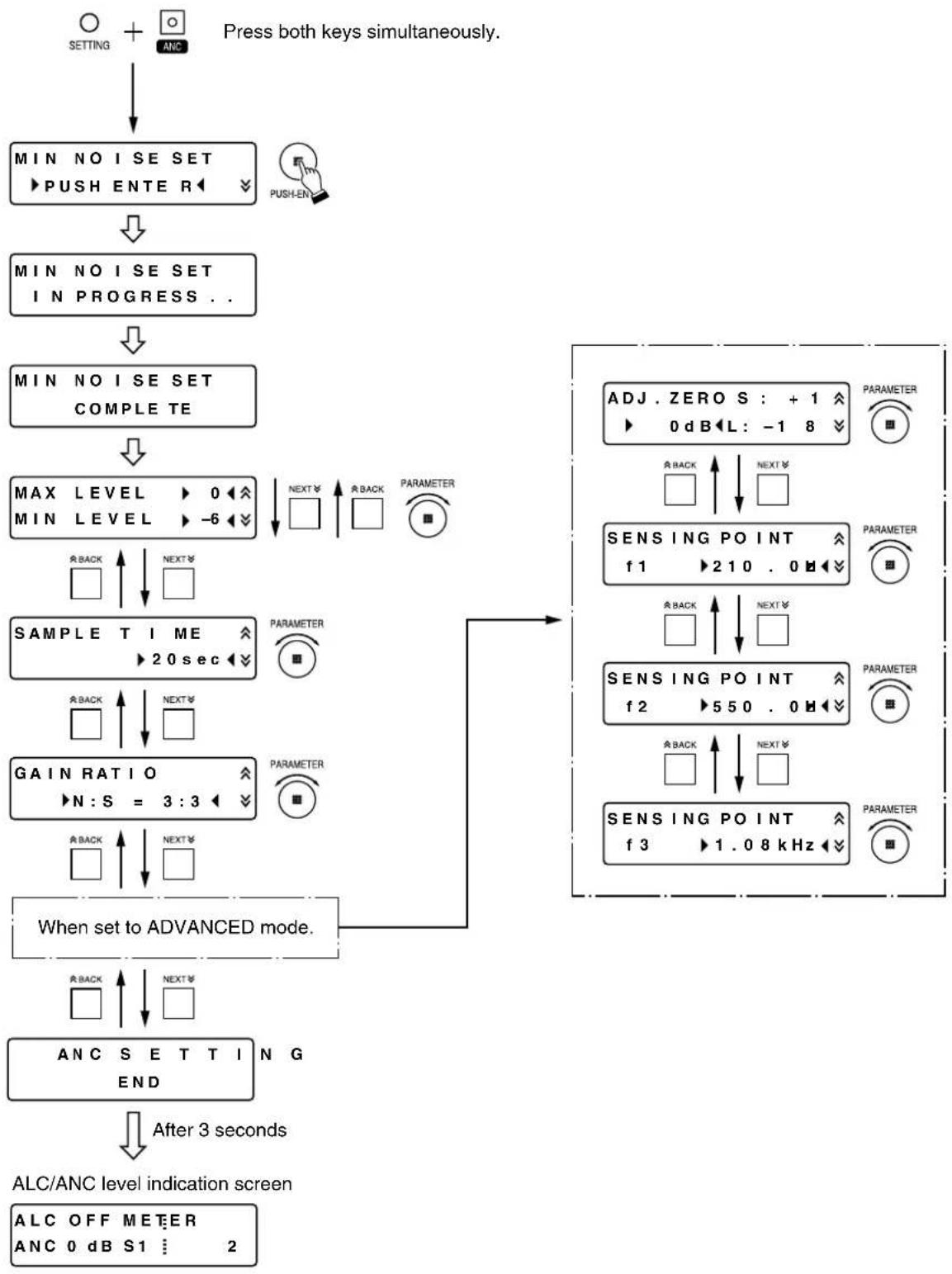
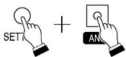
To set, press both the SETTING key and the ANC key simultaneously to enter the setting screen, then select the setting value with the PARAMETER knob.
(See p. 12; ANC function setting flow chart.)
[Enter the setting screen.]
Push both keys simultaneously.
4-1. Set the reference value of SENSOR level.
Perform this setting in the quietest circumstance.
If the PUSH-ENTER knob is pressed while the screen at right is displayed, the ambient noise level is automatically measured for 15 seconds.
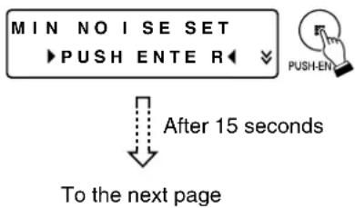
flowchart
graph TD
    A["MIN NO I SE SET"] --> B["PUSH ENTER"]
    B --> C["After 15 seconds"]
    C --> D["To the next page"]
Note
Do not input the sound source in this procedure.
4-2. Adjust the maximum output level.
Connect a sound source to INPUT 1 and adjust the level while monitoring the output sound.
Adjustable range: (MIN LEVEL +3) to 0 dB
4-3. Adjust the minimum output level.
Connect a sound source to INPUT 1 and adjust the level while monitoring the output sound.
Adjustable range: -18 to (MAX LEVEL -3) dB
4-4. Set the average time required to detect the ambient noise levels with the sensor microphone.
4-5. Adjust the ratio of ambient noise level variation to output level variation.
For example, if the ratio between N and S is set to be 3:3, the output volume level goes up by 3 dB when the ambient noise level increases by 3dB.
When the adjustment mode is set to ADVANCED:
4-6. Finely adjust the reference value (ZERO level) of the set SENSOR level.
If the reference value* differs from the actual minimum noise level, there may be a situation that the output sound is extremely loud though the ambient noise is quiet.
In such cases, correct the reference value of SENSOR level.
* The minimum noise level that has been measured in Step 4-1 is defined as reference value "ZERO level."
From the previous page
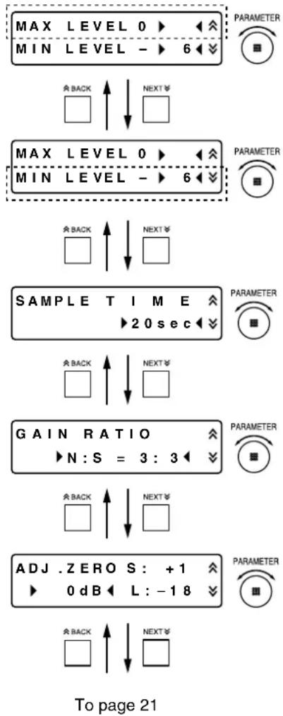
flowchart
graph TD
    A["MAX LEVEL 0"] --> B["PARAMETER"]
    C["MIN LEVEL -"] --> D["NEXT"]
    E["MAX LEVEL 0"] --> F["PARAMETER"]
    G["MIN LEVEL -"] --> H["NEXT"]
    I["SAMPLE TIME"] --> J["PARAMETER"]
    K["GAIN RATIO"] --> L["PARAMETER"]
    M["ADJ.ZEROS: +1"] --> N["PARAMETER"]
    O["0 dB L: -18"] --> P["PARAMETER"]
The explanations below are based on the assumption that the maximum output level (MAX LEVEL), minimum output level (MIN LEVEL), and gain ratio (GAIN RATIO) are as follows: MAX LEVEL = 0 dB, MIN LEVEL = -12 dB, and GAIN RATIO = 3:3.
[When the preset minimum ambient noise level is the same as the actual level]
No correction is needed.
The diagram below shows the relationship among the ambient noise level, SENSOR level, and output level.
![TOA DP-L2 - [When the preset minimum ambient noise level is the same as the actual level] - 1](/content/2026/05/831091/images/7e342d307a412b33f32fbe99c42ca112a9cb0992ee7bc46f0b8464db46bb6f64.jpg)
bar_stacked
| Level | Value | |-------|-------| | 0 | -12 | | 1 | -9 | | 2 | -6 | | 3 | -3 | | 4 | 0 | | 5 | 1 | | 6 | 2 | | 7 | 3 | | 8 | 4 | | 9 | 5 | | 10 | 6 | | 11 | 7 | | 80 dB | 80 dB |[When the preset minimum ambient noise level is extremely lower than the actual level]
In this case, the unit recognizes that the ambient noise is high even in low ambient noise condition (A) where the unit is actually used, providing sound output at high level (-3 dB in this example).
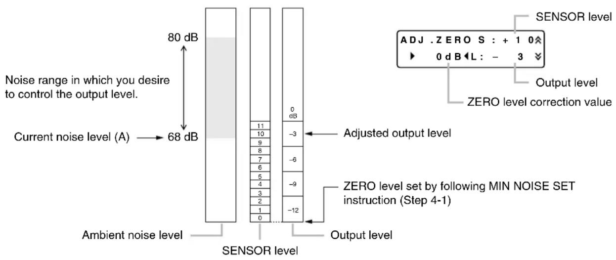
Correct the ZERO level to a higher level to obtain the optimum operation according to the cases (1) and (2) below.
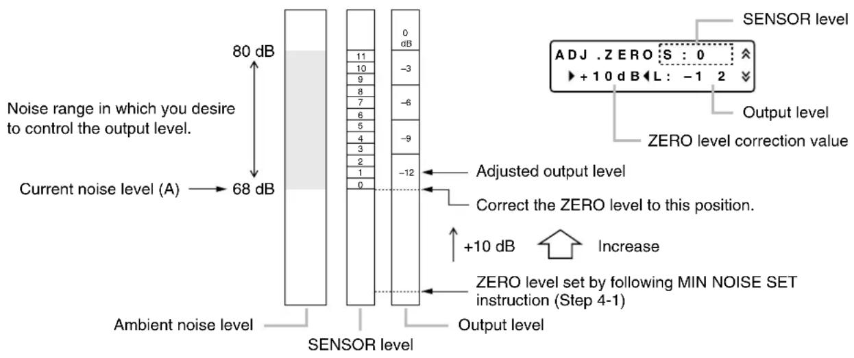
(1) If the current noise level (A) is the minimum ambient noise level when the unit is actually used, increase the ZERO level so that the SENSOR level (S) becomes "0."
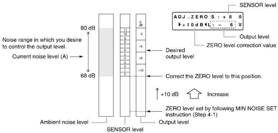
(2) If the current noise level (A) is not the minimum ambient noise level when the unit is actually used, correct the ZERO level so that the output level becomes the desired level.
[When the preset minimum ambient noise level is extremely higher than the actual level]
Correct the ZERO level to a lower level to obtain the optimum operation.
4-7. Set the ambient noise frequency to be measured.
If the frequency to be measured is known, set the SENSING POINT displayed on the screen to that frequency. If not known, leave the default frequencies unchanged.
---- Reference ----
[Default frequency] [Settable frequency range: 20 Hz to 20 kHz]
Frequencies f2 and f3 can be set in the similar manner.
6.4. Key Lock Function Settings
All front panel-mounted keys and knobs can be locked.
When the key lock operation is performed, the set parameters are stored in the unit.
6.4.1. Locking the keys
Hold down the SETTING key for 5 seconds.

flowchart
graph LR
    A["SET"] --> B["KEY LOCKED"]
    B --> C["KEY LOCKING"]
When locked keys are operated:
6.4.2. Releasing the locked state
Hold down the SETTING key for 5 seconds.

6.5. Restoring Default Settings
![[Front] Liquid crystal display BACK key TOA DIGITAL AMBIENT NOISE CONTROLLER DP-L2 PARAMETER BACK INPUT LEVEL OUTPUT LEVEL NEXT KEY RESET KEY SENSOR INPUT 1 INPUT 2 METER PUSH-ENTER NEXT V ALC MAXIMUM OUTPUT ANL ANC LEVEL POWER RESET](/content/2026/05/831091/images/ca430de562ba77f29b8a1d73265a7e0b35fd1a1b393558b87ae624012d0d7dda.jpg)
[Rear]
![POWER ON AC/DCV 50/60Hz 20W RS-232C OUTPUT 2 [4-68] OUTPUT 1 [4-68] MONITOR OUT [4-68] INPUT 2 [42-50-208] INPUT 1 [42-50-208] SENSOR [47-49X] PANITOR ON 0.5~0.75W Power switch](/content/2026/05/831091/images/b32111b7b36d7ba11e2275de5ca0a81140e2742f9565bd92e811f99162b289d1.jpg)
Following 2 methods are available to revert the unit's current settings to the factory-preset parameters.
(1) Method by using the power switch
Step 1. Turn the power switch off.
Step 2. Turn the power switch on while holding down both the BACK key and NEXT key at the same time.
Note
Keep pressing both the BACK key and NEXT key till the indication "RELEASE KEYS" appears on the LCD screen.
(2) Method by using the RESET key
Press the RESET key while holding down both the BACK key and NEXT key at the same time.
Note
Keep pressing both the BACK key and NEXT key till the indication "RELEASE KEYS" appears on the LCD screen.
7. CONNECTIONS
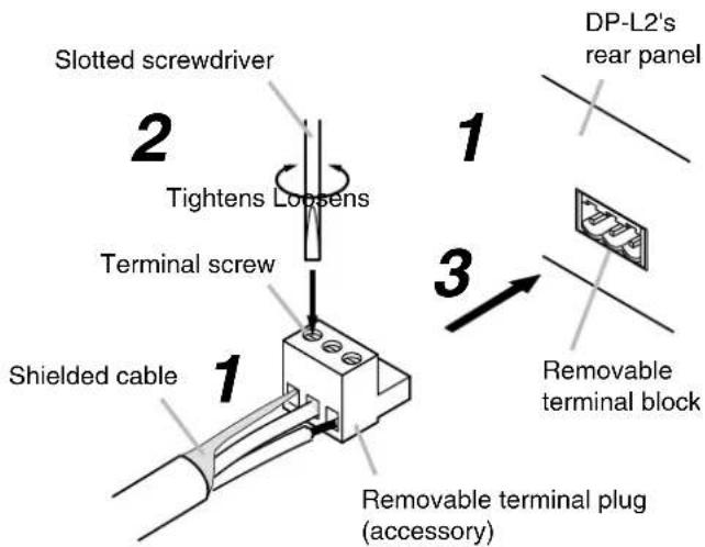
Be sure to use the supplied removable terminal plugs (3P, 4P) for connections to the removable terminal blocks.
7.1. Removable Terminal Plug Connection
Cautions
- Be sure to use shielded cables for audio signal lines.
- Avoid soldering stranded or shielded cable, as contact resistance may increase when the cable is tightened and the solder is crushed, possibly resulting in an excessive rise in joint temperatures.
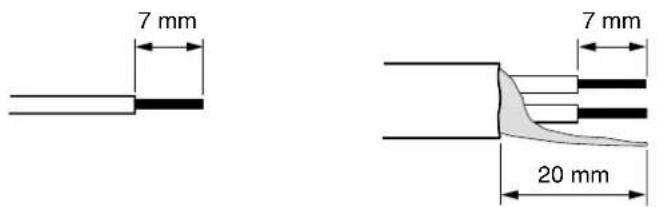
Cable end treatment
Solid or stranded cable Shielded cable
Connector connections
Step 1. Loosen the terminal screw, then insert the cable.
Step 2. Retighten the terminal screw. (Pull on the cable to ensure it is securely connected.)
Step 3. Mount the removable terminal plug to the unit.
Tip
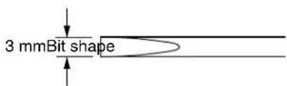
Recommended slotted screwdriver type: Screwdriver with 3 mm blade width
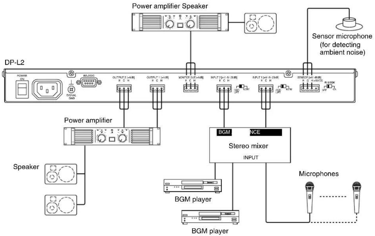
7.2. Example 1: Input and Output Connections (When Connecting to a Stereo Mixer's Outputs)
flowchart
graph TD
    A["DP-L2"] --> B["Power amplifier Speaker"]
    A --> C["Sensor microphone (for detecting ambient noise)"]
    A --> D["Power amplifier"]
    A --> E["BGM player"]
    A --> F["BGM player"]
    A --> G["Microphones"]
    H["Speaker"] --> I["RS-232C"]
    H --> J["SIGNAL 3ND"]
    H --> K["OUTPUT 2 [+40R"] E C H]
    H --> L["OUTPUT 1 [+40R"] E C H]
    H --> M["MOVITOR OUT+40R"] E C H]
    H --> N["INPUT 2 [+40-50-20R"] E C H]
    H --> O["INPUT 1 [+40-50-20R"] E C H]
    H --> P["SENSOR [+40-80R"] E D H+80/CC]
    H --> Q["PRO/ION OFF"]
    R["BGM NCE INPUT"] --> S["Output"]
    T["BGM player"] --> U["BGM player"]
7.3. Example 2: Input and Output Connections (When Connecting to a BGM Player's Outputs)
![Power amplifier Speaker Sensor microphone (for detecting ambient noise) DP-L2 POWER ON RS-320C SIGNAL 3ND OUTPUT 2 [+4dB] E.C.H OUTPUT 1 [+4dB] E.C.H MONITOR OUT[+4dB] E.C.H INPUT 2 [+4-8-20dB] CE H INPUT 1 [+4-8-20dB] CE H 3SENSOR [+4-8dB] CE +10VCD PH-2/ROM OUT ON Power amplifier BGM player Speaker](/content/2026/05/831091/images/efbcfccd317db38db1ae87c52b27848c4f313ea89343199fec3cfafe42525dee.jpg)
8. RACK MOUNTING
Notes
- Install the unit in locations where the temperature is between 0 and +40^ and the moisture is less than 90% (no dew condensation must be formed).
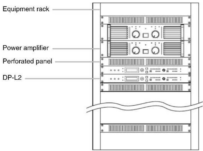
- When mounting the DP-L2 in an equipment rack, ensure good ventilation by removing all of the panels located on the rear of the rack. Also, be sure to mount a perforated panel larger than 1U size at the top and bottom of the rack.
- When mounting two DP-L2 units in an equipment rack, be sure also to mount a perforated panel larger than 1U size above and below the two units, as shown in the figure.
- When rack-mounting the DP-L2 close to a power amplifier or other heat-generating equipment, be sure to mount the unit below the equipment so that it is not affected by the rising heat.

CAUTION
When installing the unit in an equipment rack, do not to block the ventilation slots on the unit's sides and rear.
Doing so may cause heat to build up inside the unit and result in fire.
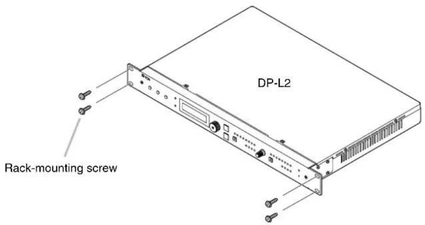
Note
As no rack-mounting screws are supplied, prepare locally the screws appropriate for the rack.
9. BLOCK DIAGRAM
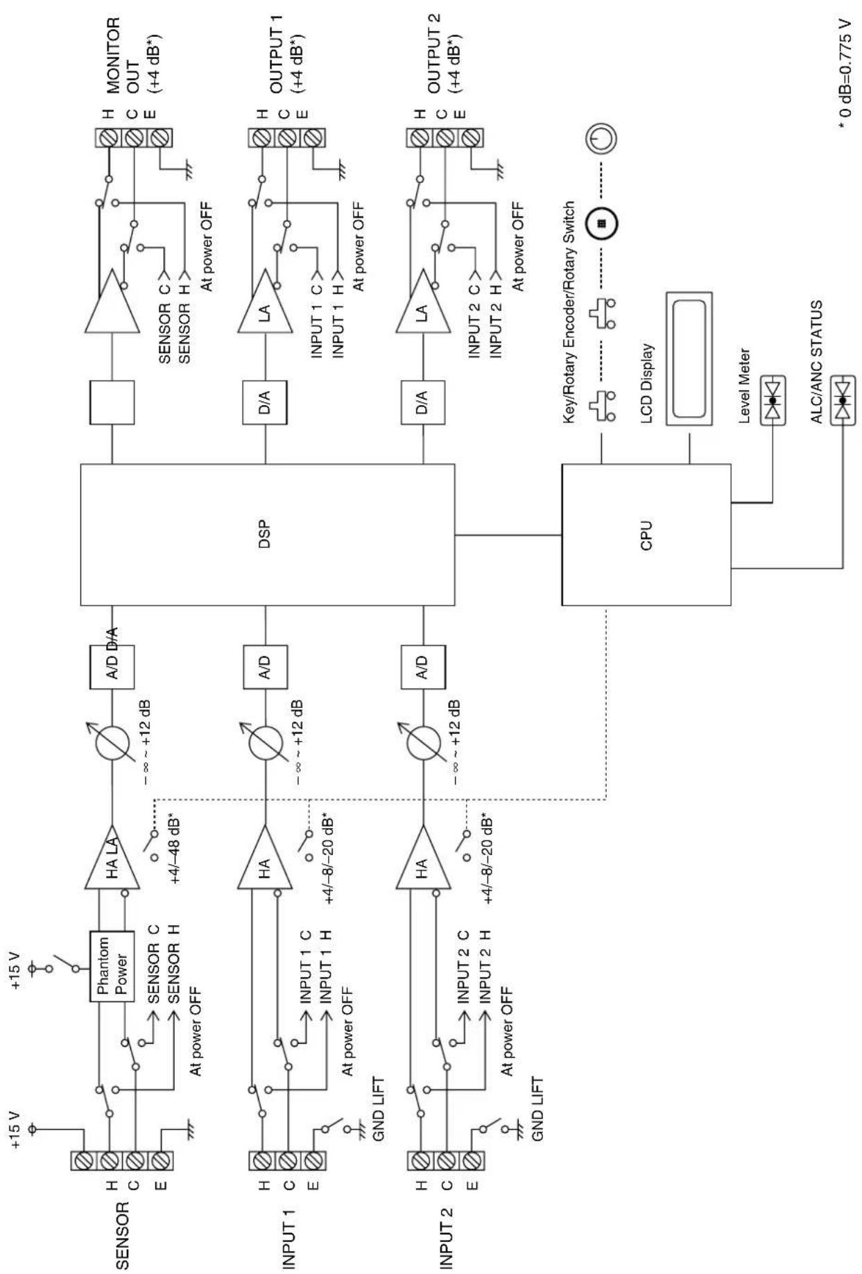
flowchart
graph TD
    subgraph_Sensor_1["SENSOR"]
        H["H"] --> PhantomPower["Phantom Power"]
        C["E"] --> PhantomPower
        H --> SensorC["SENSOR C"]
        H --> SensorH["SENSOR H"]
        H --> AtPowerOff["At power OFF"]
    end

    subgraph_Sensor_2["INPUT 1"]
        H["H"] --> HA1["HA"]
        E["E"] --> HA1
        H --> Input1C["INPUT 1 C"]
        H --> Input1H["INPUT 1 H"]
        H --> AtPowerOff["At power OFF"]
        H --> GNDLIFT["GND LIFT"]
    end

    subgraph_Sensor_3["INPUT 2"]
        H["H"] --> HA2["HA"]
        E["E"] --> HA2
        H --> Input2C["INPUT 2 C"]
        H --> Input2H["INPUT 2 H"]
        H --> AtPowerOff["At power OFF"]
        H --> GNDLIFT["GND LIFT"]
    end

    subgraph_CPU["CPU"]
        CPU --> DDA["D/A"]
        CPU --> LA["LA"]
        CPU --> DVA["D/A"]
        CPU --> KeyRotaryEncoder["Key/Rotary Encoder/Rotary Switch"]
        CPU --> LCDDisplay["LCD Display"]
        CPU --> LevelMeter["Level Meter"]
        CPU --> ALC/ANC["ALC/ANC STATUS"]
    end

    subgraph MONITOR_HA
        H --> MONITOROUT["H MONITOR OUT (+4 dB*)"]
        C --> MONITOROUT
        H --> MONITOROUT
        E --> MONITOROUT
        H --> MONITOROUT
        H --> MONITOROUT
        H --> MONITOROUT
        H --> MONITOROUT
        H --> MONITOROUT
        H --> MONITOROUT
        H --> MONITOROUT
    end

    subgraph OUTPUT_HA
        H --> OUTPUT1["H OUTPUT 1 (+4 dB*)"]
        C --> OUTPUT1
        H --> OUTPUT1
        H --> OUTPUT1
        H --> OUTPUT1
        H --> OUTPUT1
        H --> OUTPUT1
        H --> OUTPUT1
        H --> OUTPUT1
        H --> OUTPUT1
        H --> OUTPUT1
        H --> OUTPUT1
        H --> OUTPUT1
        H --> OUTPUT1
        H --> OUTPUT1
        H --> OUTPUT1
        H --> OUTPUT1
        H --> OUTPUT1
        H --> OUTPUT1

    subgraph_OUTPUT_2["H OUTPUT 2 (+4 dB*)"]
        H --> OUTPUT2["H OUTPUT 2 (+4 dB*)"]
        C --> OUTPUT2
        H --> OUTPUT2
        H --> OUTPUT2
        H --> OUTPUT2
        H --> OUTPUT2
        H --> OUTPUT2
        H --> OUTPUT2
    end

    note right of CPU: *0 dB=0.775 V
10. RECORDING TABLE OF FUNCTION SETTINGS
It is recommended that you note the current setting contents in this recording table for future reference.
| Function | Mode* | Setting item | Default (presetting) | Setting content |
| SETTING | SETTING MODE | NORMAL | □ NORMAL ADVANCED | |
| SUMMING MODE | OFF | □ OFF OUT=CH1+CH2 | ||
| SENSOR SENSE | +4 dB | □ +4 dB □ -48 dB | ||
| SENSOR FILTER | A WEIGHT | □ FLAT A WEIGHT | ||
| ALC | GATE LEVEL | -60 dB | dB | |
| S | INPUT 1 | -60 dB | dB | |
| S | INPUT 2 | -60 dB | dB | |
| INPUT SENSE SET | AUTO | dB | ||
| A + S | INPUT 1 | +4 dB | □ -20 □ -8 +4 dB | |
| A + S | INPUT 2 | +4 dB | □ -20 □ -8 +4 dB | |
| BGM LEVEL | 0 dB | dB | ||
| ANC | MIN NOISE SET | AUTO | — | |
| MAX LEVEL | 0 | |||
| MIN LEVEL | -6 | |||
| SAMPLE TIME | 0 : 20 | : | ||
| GAIN RATIO | 3 : 3 | : | ||
| A | ADJ. ZERO | 0 dB | dB | |
| A | SENSING POINT f1 | 210.0 Hz | Hz | |
| A | SENSING POINT f2 | 550.0 Hz | Hz | |
| A | SENSING POINT f3 | 1.08 kHz | Hz |
* Blank: NORMAL mode
A: ADVANCED mode
S: SUMMING mode
11. SPECIFICATIONS
| Power Source | CU version: 110 – 120 V AC, 50/60 HzCE version: 220 – 240 V AC, 50/60 Hz |
| Power Consumption | CU version: 20 W, 300 mACE version: 20 W, 220 mA |
| Frequency Response | 20 – 20,000 Hz (±1 dB) |
| Sampling Frequency | 48 kHz |
| Dynamic Range | Over 108 dB (IHF-A weighted) |
| Distortion | Under 0.006%, 1 kHz, +4 dB* input/output (20 – 20,000 Hz BPF) |
| Input | Sensor input (Ambient noise sensor microphone input):+4/-48 dB* changeable, 10 kΩ, electronically-balanced, removable terminal block (4 pins), phantom power (+15 V DC, can be turned on or off with Phantom switch) with +15 V DC terminalInput 1, 2: +4/-8/-20 dB* changeable, 15 kΩ, electronically-balanced, removable terminal block (3 pins) |
| Output | Monitor output: +4 dB*, 600 Ω, electronically-balanced, removable terminal block (3 pins)Output 1,2: +4 dB*, 600 Ω, electronically-balanced, removable terminal block (3 pins) |
| A/D Converter | 24 bit |
| D/A Converter | 24 bit |
| Signal Processing | Automatic level control function:Level meter (4 LED meters), Automatic input signal level control function,Automatic input sensitivity setting function (+4/-8/-20 dB*), Noise gate level setting (-99 to -3 dB) |
| Ambient noise control function:Level meter (4 LED meters), BGM/Announce level control function, Automatic sensor input reference level measuring function, Sensor input reference level fine adjustment function, Maximum output signal level control (-15 to 0 dB), Minimum output signal level control (-18 to -3 dB), Sample time setting (10 s, 20 s, 30 s, 1 min, 5 min), Gain ratio setting (6:3, 5:3, 4:3, 3:3, 3:4, 3:5, 3:6), Ambient noise measuring frequency setting (20 – 20,000 Hz, 3 points) | |
| Maximum output signal level control function: -12, -6, 0, +4, +6, +12, +18, +24 dB* | |
| Input level indicator: 8 LEDs indicator | |
| Output level indicator: 8 LEDs indicator | |
| Other Feature | Phantom power switch (sensor input), Ground lift switch (INPUT 1, INPUT 2), Key lock function, Input/Output bypass function in power off |
| Operating Temperature | 0°C to 40°C |
| Operating Humidity | Under 90% RH (no condensation) |
| Finish | Pre-coated steel plate, black, 30% gloss |
| Dimensions | 482 (w) x 44 (h) x 303 (d) mm |
| Weight | 3.7 kg |
* 0 dB = 0.775 V
Note
- The design and specifications are subject to change without notice for improvement.
- Prepare locally the sensor microphone for detecting ambient noise.
- Accessories
Power cord (2 m) 1
Removable terminal block (3 pins) 5
Removable terminal block (4 pins) 1
- TABLE OF CONTENTS
- SAFETY PRECAUTIONS
- Safety Symbol and Message Conventions
- WARNING
- When Installing the Unit
- When the Unit is in Use
- CAUTION
- GENERAL DESCRIPTION
- FEATURES
- HANDLING PRECAUTIONS
- Note
- Modifications
- NOMENCLATURE AND FUNCTIONS
- Power indicator
- Sensitivity controls
- SETTING key
- METER indication selector key
- Liquid crystal display
- PARAMETER/PUSH-ENTER knob
- BACK key
- NEXT key
- ALC key
- INPUT LEVEL indicator
- ALC LEVEL indicator
- MAXIMUM OUTPUT level control
- ANC key
- OUTPUT LEVEL indicator
- ANC LEVEL indicator
- RESET key
- [Rear]
- Power switch
- AC inlet
- Functional earth terminal
- RS-232C Communication port (Non LPS)
- OUTPUT 1 and 2 terminals (+4 dB\*, 600Ω)
- MONITOR OUT terminal (+4 dB\*, 600Ω)
- INPUT 1 and 2 terminals
- Ground lift switches
- SENSOR input terminal
- PHANTOM power switch
- SETTINGS
- Setting Operations and Setting Screens
- Keys and knobs used in settings
- SETTING Key
- METER Indication Selector Key
- PARAMETER/PUSH-ENTER Knob
- BACK Key
- NEXT Key
- ALC Key
- ANC Key
- On-screen indications
- Setting Flow Charts
- System setting flow chart
- ALC function setting flow chart
- ANC function setting flow chart
- ALC and ANC functions ON/OFF settings
- INPUT LEVEL, OUTPUT LEVEL, and ALC LEVEL indication selection
- [Level indicators and indicated channel table]
- Setting Procedures
- Step 1. Perform system settings.
- 1-1. Set the adjustment mode.
- 1-2. Set the SUMMING mode.
- 1-3. Set the SENSOR input sensitivity.
- 1-4. Set the SENSOR input characteristics.
- Tip
- When the adjustment mode is set to NORMAL, and SUMMING mode to OFF:
- When the adjustment mode is set to NORMAL, and SUMMING mode to OUT = CH1+CH2:
- When the adjustment mode is set to ADVANCED, and SUMMING mode to OFF:
- When the adjustment mode is set to ADVANCED, and SUMMING mode to OUT=CH1+CH2:
- Step 4. Set the ANC function.
- When the adjustment mode is set to ADVANCED:
- [When the preset minimum ambient noise level is the same as the actual level]
- [When the preset minimum ambient noise level is extremely lower than the actual level]
- [When the preset minimum ambient noise level is extremely higher than the actual level]
- Key Lock Function Settings
- Locking the keys
- Releasing the locked state
- Restoring Default Settings
- Method by using the power switch
- Method by using the RESET key
- CONNECTIONS
- Removable Terminal Plug Connection
- Cautions
- Cable end treatment
- Connector connections
- Example 1: Input and Output Connections (When Connecting to a Stereo Mixer's Outputs)
- Example 2: Input and Output Connections (When Connecting to a BGM Player's Outputs)
- RACK MOUNTING
- Notes
- BLOCK DIAGRAM
- RECORDING TABLE OF FUNCTION SETTINGS
- SPECIFICATIONS
- - Accessories
Brand : TOA
Model : DP-L2
Category : Processor