
EACEPE4 - Air conditioner Furrion - Free user manual and instructions
Find the device manual for free EACEPE4 Furrion in PDF.


| Product Type | Rooftop Air Conditioner |
| Model | EACEPE4 |
| Cooling Capacity | 15,500 BTU/h |
| Dehumidification | Up to 3.2 pints/h |
| Electrical Rating | 115V~60Hz, 1 Phase |
| Power Consumption (Cooling) | 1720 W |
| Current (Cooling) | 15.4 A |
| Dimensions (L x W x H) | 34 7/8" x 27 5/8" x 13 5/8" |
| Weight | Approx. 100 lbs (45 kg) |
| Refrigerant | R410A |
| Recommended Roof Opening | 14 1/4" x 14 1/4" (+½") |
| Roof Thickness Compatibility | 3" to 6" |
| Filter Type | Washable, replaceable |
| Control Options | Wall thermostat (sold separately), single or multi-zone |
| Fan Speeds | Low, Medium, High, Auto |
| Special Features | Sleep mode, mood light, compressor time delay, auto fan |
| Error Display | LCD error codes (E1-E5, L0) |
| Installation | Must be installed by qualified personnel |
| Safety | Disconnect power before service, proper grounding required |
| Warranty | 1 year limited |
Frequently Asked Questions - EACEPE4 Furrion
User questions about EACEPE4 Furrion
0 question about this device. Answer the ones you know or ask your own.
Ask a new question about this device
Download the instructions for your Air conditioner in PDF format for free! Find your manual EACEPE4 - Furrion and take your electronic device back in hand. On this page are published all the documents necessary for the use of your device. EACEPE4 by Furrion.
USER MANUAL EACEPE4 Furrion
FACR15SA-PS/FACR15SA-BL

natural_image
Black Furrion device with red LED display and ventilation grille (no visible text or symbols on body)
natural_image
3D rendered object with a dark, reflective surface and a triangular indentation (no text or symbols)FACT12LA-PS/FACT12LA-BL
FACT12SA-PS/FACT12SA-BL
(Sold Separately)
Thank you for purchasing this Furrion® Chill™ Rooftop Air Conditioner. Before operating your new product, please read these instructions carefully. This will ensure safe use and reduce the risk of injury. This instruction manual contains information for installation, operation, maintenance of the product and safe use.
Please keep this instruction manual in a safe place for future reference. Be sure to pass on this manual to any new owners of this product.
The manufacturer does not accept responsibility for any damages due to not observing these instructions.
Contents
Contents....1
Important Safety Instructions....2
Handling the Device 2
Handling Electrical Cables....3
Before Installing 4
What's in the Box....4
Choosing Proper Location for the Air Conditioner....4
Roof Preparation 6
Air Distribution Duct Sizing and Design....7
Air Distribution System Installation....8
Laying the Connecting Cables 9
Installation 10
Installing the Rooftop Unit....10
Installing the Wall Thermostat (model: FACW12SA-BL/FACW12PA-BL/FACW12ZA-
BL, sold separately)....10
Installing the Air Distribution Box (for FACT12LA-PS/FACT12LA-BL/FACT12SA-
PS/FACT12SA-BL models only, same for both ducted and non-ducted models,
sold separately)....11
Cleaning and Maintenance ....16
Troubleshooting....17
Specifications....18
Wiring Diagram....19
Multi Zone Wiring Diagram 20
Important Safety Instructions
This manual has safety information and instructions to help users eliminate or reduce the risk of accidents and injuries. Please read this instruction manual carefully before installation and start-up, and store it in a safe place for future reference. If you pass on the device to another person, hand over this instruction manual along with it.
- The manufacturer accepts no liability for damage in the following cases:
– Faulty assembly or connection
– Damage to the product resulting from mechanical influences and excess voltage - Alterations to the product without express permission from the manufacturer
- Use for purposes other than those described in the operating manual
- The following basic safety information should be heeded when using electrical devices to protect against:
- Electric shock
- Fire hazards
- Injury
- All Furrion product referenced in this manual is to be installed in accordance with local and national codes, including the latest editions of the following standards:
USA:
- NFPA 1192
- NFPA 70
Canada:
-C22.1
- CSA Z240
Handling the Device
WARNING
- Installation and repair of the rooftop air conditioner must only be carried out by qualified personnel who are familiar with the risks involved and the relevant regulations. Inadequate repairs may cause serious hazards.
- Electrical devices are not toys. Keep electrical devices out of reach of children or elderly persons. Do not allow them to use electrical devices without supervision.
- Prevent inexperienced people from using the device without supervision.
- Do not undo the upper cover of the rooftop air conditioner in the event of a fire. Use approved extinguishing agents instead. Do not use water to extinguish fires.
CAUTION
- The rooftop air conditioner must be installed securely so that it cannot fall down.
- Only operate the rooftop air conditioner if you are certain that the housing and the cables are not damaged.
- Do not use the rooftop air conditioner near flammable fluids or in closed rooms.
- Make sure no combustible objects are stored or installed near the air outlet. A distance of at least 20" must be kept.
- Do not reach into air outlets or insert any foreign objects into the device.
- Only use the device as intended.
- Do not make any alterations or conversions to the device.
- If faults occur in the refrigerant circuit, the system must be checked by a certified service technician and repaired properly. The refrigerant must never be released into the air.
Handling Electrical Cables
WARNING
The electrical power supply must only be connected by a qualified electrician.
CAUTION
- Refer to NEC (National Electric Code) for proper sizing of wire gauge (awg) based on cable length and overcurrent protection rating that is suppling power to the air conditioner.
- See rooftop unit nameplate for proper overcurrent protection sizing.
-
Attach and lay the cables so that they cannot be tripped over or damaged.
-
Only a qualified electrician should connect the rooftop air conditioner to electrical power.
- Do not lay loose or bent cables next to electrically conductive materials.
- Do not pull on the cables.
- Use cable ducts to lay cables through walls with sharp edges.
- Refer to rooftop unit nameplate and NEC for proper power supply rating.
Before Installing
Read this installation manual completely before installing the rooftop air conditioner.
The following tips and instructions must be observed while installing the rooftop air conditioner.
What's in the Box
Open the box and remove the components from carton. Make sure you have all the following items included in the packaging, if any item is missing, contact your dealer.
Rooftop Air Conditioner:
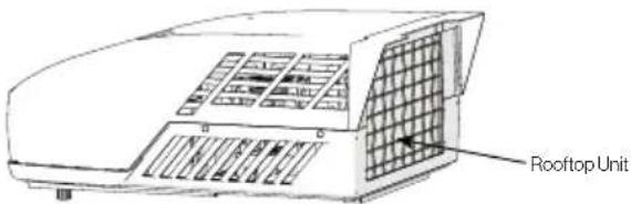
- Rooftop unit x 1
- Warranty Leaflet x 1
Air Distributor Box (sold separately):
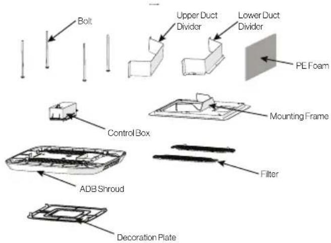
• Upper Duct Divider x 1
- Lower Duct Divider x 1
- Bolt x 4
- Mounting Frame x 1
• Control Box (sold separately) x 1
• Air Distribution Box (ADB) Shroud x 1
- Filter x 2
- Decoration Plate x 1
• Self-tapping Screws x 6 - PE foam x 1
• Instruction Manual x 1
Choosing Proper Location for the Air Conditioner
IMPORTANT: The roof must be designed to support the weight of the rooftop unit and the weight of 2 installers standing on the roof.
There are two ways of installing the rooftop air conditioner:
- Using the existing roof vent opening in the vehicle roof.
- Making a new opening. In this case the opening should be reinforced by an appropriate frame as required.
Existing Roof Vent Opening
The air conditioner is designed to fit over an existing 14" roof vent opening.
New Opening
When no roof vent is available or another location is desired, the following is recommended:
- For one unit installation - the air conditioner should be mounted slightly forward of center (front to back) and centered from side to side.
- For two unit installations, install one air conditioner one third from the front of the RV and the other air conditioner two thirds from the front of the RV, aligned in the center.
It is preferred that the air conditioner be installed on a relatively flat and horizontal roof section measured when the RV is parked on a level surface.
NOTE: A 15° slant to either side or front to back is acceptable for all units. If the roof exceeds 15° please use an exterior leveling shim to make air conditioner level.
After the Location Has Been Selected:
- Check for obstructions in the area where the air conditioner will be installed.

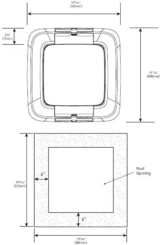
- Check the inside of the RV for return air kit obstructions. (i.e. door openings, room dividers, curtains, ceiling fixtures, etc.) Allow 6" (152mm) space from the opening to account for any potential return air kit obstructions.
Roof Preparation
Opening Requirements - Before preparing the ceiling opening, decide on the type of system options. Read all of the following instructions before beginning the installation.
WARNING
Fire/Electric Shock Hazard
- Make sure there are no obstacles inside the RV roof, floor and walls, such as wires and pipes.
- Shut off the gas supply and disconnect the 115VAC power from the RV before drilling or cutting into the RV. Failure to obey these warnings could result in death or serious injury.
Roof Thickness
The installation of air conditioner suits for roof thickness from 3" (75mm) to 6" (152mm). For other thickness, please contact Furrion or Furrion authorized service agent.
Installing in an Existing
Opening
- Unscrew and remove the roof vent.
- Remove all caulking compound around the opening.
- If the opening exceeds 1414 x 1414 (+ 12 ), it will be necessary to resize the opening to 1414 x 1414 (+ 12 ). If the opening is less than 1414 x 1414 (+ 12 ), it must be enlarged.

Making a New Opening
If a roof vent opening will not be used, a 1414 " x 1414 " (+½") (362mm x 362mm) opening must be cut through the roof and ceiling of the RV. This opening must be located between the roof reinforcing members.
The 14 ^1/4 " x 14 ^1/4 " (+ ^1/2 ") opening is part of the return air system of the air conditioner and must be finished in accordance with NFPA Standard 501C Section 2.7.2.
- Mark a 1414 " x 1414 " (+½") square on the roof and carefully cut an opening.

- Using the roof opening as a guide, cut a matching hole in the ceiling.
NOTE: Maintain structural integrity. Otherwise damage to product and/or RV could occur. Always observe the following guidelines while structuring the opening.
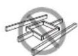
Do not cut roof structure or rafters
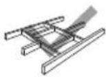
Good: rafters supported by cross beams

Good: location between roof rafters
- The opening created must be framed to provide adequate support and prevent air from being drawn from the roof cavity.
- Lumber 34 " or more in thickness must be used. Remember to provide an entrance hole for power supplies, wall thermostat and furnace wiring for connections. Leave 15" (381mm) minimum at the front of the opening.

Air Distribution Duct Sizing and Design
The installer of this system must design the air distribution system for their particular application.
NOTE: Make sure ductwork will NOT bend or collapse during and after installation, and that it is correctly insulated and sealed. Otherwise, damage to roof structure and ceiling could occur. The following requirements must be met for properly operate the unit:
| Roof Cavity Depth | 3"-6" (75mm-152mm) | |
| Duct Cross Sectional Area | 21 Sq. In. Min. | |
| Duct Size | Depth | 112" Min. - 212" Max. (38mm Min. - 63.5mm Max.) |
| Width | 7" Min. - 10" Max. (178mm Min. - 254mm Max.) | |
| Total Duct Length | 15Ft. Min. - 40Ft. Max. (4.5m - 13m) | |
| Duct Length (short run) | 13 Total Duct Length | |
| Register Requirements per A/C Unit | Number Required | 4 Min. - 8 Max. |
| Supply Register Free Air Area | 14 Sq. In. (90 sq. cm) | |
| Return Register Free Air Area | 40 Sq. In. (258 sq. cm) | |
| Distance From Duct End | 5" Min. - 8" Max. (127mm Min. - 203mm Max.) | |
| Distance From Elbow | 15" (381mm) | |
| Total System Static Air Pressure | Blower at High Speed, Filter & Grille In Place | 0.55 - 1.10 In. W.C. |
- Properly insulate and seal all discharge air ducts to prevent condensation from forming on their surfaces or adjacent surfaces during operation of the unit. This insulation must be R-7 minimum.
TOP VIEW (BACK OF RV)

SIDE VIEW (TOWARD BACK OF RV)

- Return air openings must have 80 square inches (516 square centimeters) minimum free area including the filter.
- Return air to the unit must be filtered to prevent dirt accumulation on the unit cooling surface.
Air Distribution System Installation
It is the responsibility of the installer to review each RV floor plan to determine the following items in conjunction with "Air Distribution Duct Sizing and Design" section on Page 8.
NOTE: Alternate configurations and methods may be used which will allow the unit to operate properly, however, these alternate configurations and methods MUST be approved by Furrion in writing.
- Duct size
- Duct layout
- Register size
- Register location
• Thermostat location - Indoor temperature sensor location (if applicable)

Laying the Connecting Cables
The rooftop air conditioner must be connected to an electric circuit which is able to supply the required power supply (see chapter "Specification").
NOTE: The supply wire must be located in the front portion of the roof opening. The power supply must be equipped with a time delay fuse or circuit breaker. See rooftop unit nameplate for rating.
! DANGER
Electrical Shock Hazard
- Disconnect power before servicing.
Failure to obey this warning could result in death or serious injury. -
Provide grounding in compliance with all applicable electrical codes.
Failure to obey this warning could result in death or serious injury. -
Refer to the applicable electric code guidelines for sizing the appropriate wire gauge, length and type.
- Route a 115VAC supply wire with ground wire from the time delay fuse or circuit breaker box to the roof opening.
NOTE: Refer to rooftop unit nameplate and applicable code for proper installation.
-
Use approved method to protect the wire where it passes through the opening.
-
Feed the 115VAC cable through the opening into the vehicle interior. Make sure at least 15" (381mm) of supply wire extends into the roof opening. This ensures an easy connection at the control box.
Installation
Installing the Rooftop Unit
CAUTION
- The rooftop unit weighs approximately 100 pounds (45 kg). To prevent back injury, use a mechanical hoist when lifting or moving the unit. Failure to obey this warning could result in injury.
- Do not slide unit. It may damage the gasket at the bottom of the rooftop unit and cause leakage.
-
Do not grasp the ventilation slots to lift the rooftop unit up.
-
Grasp the bottom of two sides of the unit, lift and position the rooftop unit into the prepared opening using the gasket at the bottom of the rooftop unit as a guide. (Fig. 1)

This completes the outside installation of the rooftop unit. Minor adjustments can be done from inside of the RV if required.
Installing the Wall Thermostat (model: FACW12SA-BL/FACW12PA-BL/FACW12ZA-BL, sold separately)
There are 3 types of wall thermostat for you to select.
- FACW12SA-BL: Single zone basic wall thermostat
- FACW12PA-BL: Single zone premium wall thermostat
- FACW12ZA-BL: Multi zone wall thermostat
Based on the wall thermostat version you selected. Please refer to the separate instruction manual on how to install the wall thermostat to the RV.
Installing the Air Distribution Box (for FACT12LA-PS/FACT12LA- BL/FACT12SA-PS/ FACT12SA-BL models only, same for both ducted and non-ducted models, sold separately)
The rooftop unit is fixed on the RV roof using 4 long bolts through the mounting frame from the interior of the RV ceiling.
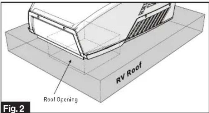
- Check the gasket alignment of the rooftop unit inside the RV over the roof opening and adjust as necessary by lifting and moving slightly. (Fig. 2)
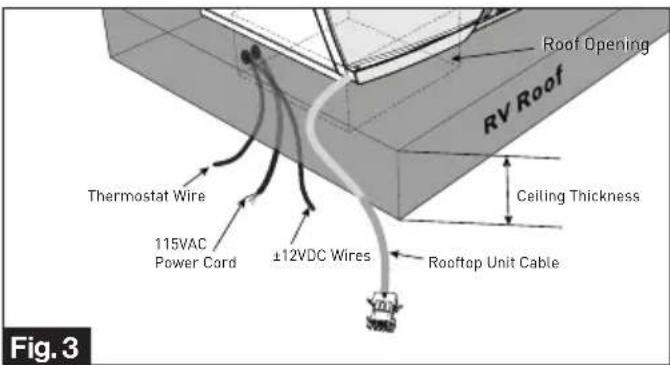
- Reach up into the return air opening and pull the rooftop unit electric cord, 115VAC power cord, ±12VDC and thermostat wires. (Fig. 3)
- Install the assembled mounting frame and the lower duct divider into the rooftop opening. Make sure the "THIS WAY FRONT" mark is facing front (the direction of the vehicle) while installing. (Fig. 4)

- Fix the assembled mounting frame and lower duct divider into the rooftop unit using 4 bolts provided. (Fig. 5)

NOTE: If bolts are left loose there may not be an adequate roof seal or if over tightened, damage may occur to the rooftop base or mounting frame. Evenly tighten the four bolts to a torque of 40 to 50 inch pounds. This will compress the roof gasket to approximately 9/16" .
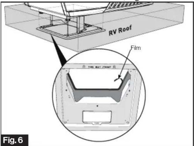
- Pull to remove the film off the double sided sticky tape on the inner side of the lower duct divider. (Fig. 6)
- Stick the upper duct divider into the assembled mounting frame. NOTE: Make sure the upper duct divider is compressing the top foam on the base of the unit, and compress to doubled sided tape on the lower duct divider to ensure a positive retention. (Fig. 7)

- Peel to remove the release paper from the PE foam, overlap the sticky side over all gaps and compress to seal and insulate the entire section. (Fig. 8)

- Use self adhesive foil tape to seal all remaining gaps around the duct divider, PE foam and roof opening, completely sealing duct edges as required.
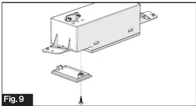
- Remove the cable compartment cover using a Phillips screw driver. (Fig. 9)
natural_image
Technical line drawing of an electronic device housing with a base plate and mounting bracket (no text or symbols)! DANGER
Electrical Shock Hazard
- Disconnect power before servicing. Failure to obey this warning could result in death or serious injury. - Provide grounding in compliance with all applicable electrical codes. Failure to obey this warning could result in death or serious injury.
- Loosen the strain relief on top of the control box and let the 115VAC power cord pass through. (Fig. 10)
NOTE: Always follow the color code while connecting the cables.
Black - Hot
White - Neutral
Green/yellow - Ground

natural_image
Technical line drawing of a mechanical device with an inset close-up showing internal components (no text or symbols)- Tighten the cable clip until the cable is properly restrained.
NOTE: Do not over tighten.
- Fit all cables into the cable compartment and tuck any excess wires up out of the way. Tighten the cover with screw. (Fig. 11)

natural_image
Technical line drawing of a mechanical assembly with mounting base and internal components (no text or symbols)- Lock the freeze sensor onto the pipe of the evaporator. Connect the freeze sensor cable of the control box to the freeze sensor of the rooftop. (Fig. 12)

- Connect the other wires of the rooftop unit cable to the control box. (Fig. 13)
- Furnace + / Furnace - Cable:
Connect to Furnace.
- Analog Cable (if applicable):
Connect to external analog input.
- LED Cable: Connect to LED stripe.
- Wall Thermostat Cable: Connect to wall thermostat and another zone's control box if applicable. (See multi zone wiring diagram in page 21).
- Rooftop Cable: Connect to rooftop unit.
- 115VAC Power Cord: Connect to 115VAC power source.

- Set up the control box dip switches as indicated in the illustration and table below (Fig. 14):

| ZoneSelection* | DIP 1:DIP2 | DIP 1 DIP 2 ZONE | |
| OFF OFF ZONE1 | |||
| OFF ON ZONE2 | |||
| ON OFF ZONE3 | |||
| ON ON ZONE4 | |||
| Heat Pump(selectedmodels) | DIP 3 Reserved | ||
| Furnace DIP 4 | OFF | FurnaceOff | |
| ON | FurnaceOn | ||
| Electric Heat(selectedmodels) | DIP 5 | OFF | Heat StripeOff |
| ON | Heat StripeOn | ||
| Analog /Digital | DIP 6 | OFF Digital | |
| ON Analog | |||
*NOTE: DIP1 and DIP2 are for Multi Zone only.
- Connect the wall thermostat cable and 12VDC power cable to the control box.(Fig. 15)

- Install the control box into the mounting frame and fix with 2 self-tapping screws (one piece each side). (Fig. 16)

- Connect the LED cable (if applicable) from the ADB shroud to the control box. (Fig. 17)

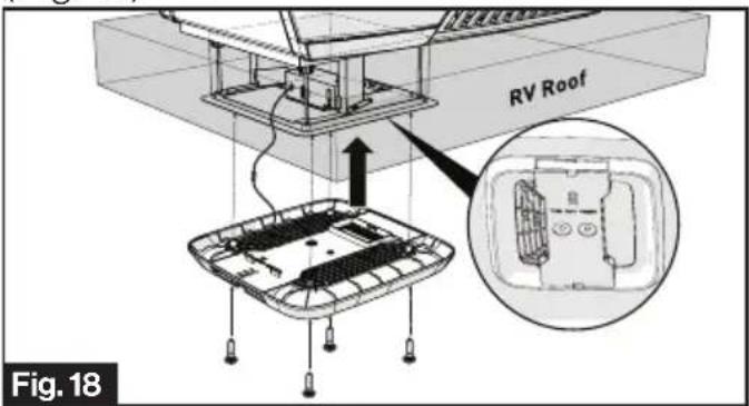
- Install the Air Distribution Box (ADB) shroud over the mounting frame and fix with 4 self-tapping screws.
NOTE: Make sure the "THIS WAY FRONT" mark is facing front (the direction of the vehicle) while installing. (Fig. 18)
- Align the filter tabs with mating notches and push to snap the filters into the ADB shroud. (Fig. 19)

- Align the decoration plate tabs with the mating notches on the ADB shroud and push to snap the decoration plate into place. (Fig. 20)

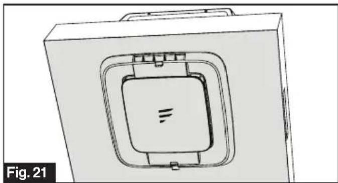
- Your new rooftop air conditioner has now been fully installed in the RV roof. (Fig. 21)
natural_image
Technical line drawing of a mechanical component with a square recess and internal slot (no text or symbols)Based on the wall thermostat version you selected. Please refer to the separate instruction manual on how to operate your RV air conditioning system.
Cleaning and Maintenance
A blocked filter will impair the cooling and heating performance of the unit significantly.
The filter must be cleaned periodically to ensure that it does not become clogged with dust and other particles. The state of the filter can be ascertained from its appearance. If it appears dirty or clogged then it should be cleaned.
WARNING
Airborne particles can pose a health risk, particularly to young children and the elderly. Ensure that filters are cleaned in a safe and well ventilated area.
To Clean the Filter
The filter should be cleaned every four weeks or more when in use. Prolonged use, higher concentrations of airborne particles and various other factors may result in the filters needing to be cleaned more often.
- Remove the decoration plate from the air conditioning system by pushing the side tabs to release. (Fig. 22)

natural_image
Technical diagram of a vehicle interior showing internal compartments and a rear view (no text or symbols)- Remove the filters by pushing the tabs to release. (Fig. 23)

-
The filter can be washed with warm soapy water. Care must be taken to avoid ripping the fabric.
-
Replace the filters and decoration plate, by reversing the above process.
NOTE: The filter must be completely dry before re-installation.
To Replace the Filter
Filter changes should be carried out depending on the amount of use, it is recommended to change at least every 12 months. Never operate the air conditioning system without a filter, since this can decrease performance and indoor air quality.
Replacement return air filters can be ordered directly from Furrion.
Troubleshooting
| Problem Cause Remedy | ||
| Rooftop air conditioner Abnormal shutdown | Freeze sensor has tripped. Outer | temperature is too low or all air nozzles are closed. |
| Not cool enough | Refrigerant leakage | Contact an authorized service agent or Furrion (see the detail contact info at the back page of this manual). |
| The rooftop air conditioner is not set to cooling. | Set the rooftop air conditioner to cooling. | |
| The set temperature is too high. | Select a lower temperature. | |
| The evaporator fan is damaged. | Contact an authorized service agent or Furrion (see the detail contact info at the back page of this manual). | |
| The condenser fan is damaged. | Contact an authorized service agent or Furrion (see the detail contact info at the back page of this manual). | |
| The air intake grilles are blocked or obstructed. | Remove any leaves and other dirt from the ventilation grilles of the rooftop air conditioner. | |
| The blower is defective. | Contact an authorized service agent or Furrion (see the detail contact info at the back page of this manual). | |
| Water enters the vehicle | The condensation water drainage openings are clogged up. | Clean the drainage openings for condensation water. |
| The seals are damaged. | Contact an authorized service agent or Furrion (see the detail contact info at the back page of this manual). | |
| Rooftop air conditioner does not switch on | No supply voltage connected. | Check the power supply. |
| The voltage is too low. | Contact an authorized service agent or Furrion (see the detail contact info at the back page of this manual). | |
| Fuse blown or circuit protector tripped. | Check the electrical fuse of the power supply. | |
Specifications
Specification
| PERFORMANCE | |||
| Model Number | FACR13SA-PSFACR13SA-BL | FACR14SA-PSFACR14SA-BL | FACR15SA-PSFACR15SA-BL |
| Cooling Capacity (Btu/h) 13,500 14,500 | 15,500 | ||
| Dehumidification (pint/h) 2.5 2.7 3.2 | |||
| Applicable vehicle length (feet) 23 26 31 | |||
| Refrigerant R410A R410A R410A | |||
| Charge (Oz) 15.9 19.8 23.1 | |||
| Roof top Unit Dimensions (L x W x H) (inch) | 3478 × 2758 × 1358 | 3478 × 2758 × 1358 | 3478 × 2758 × 1358 |
| ELECTRICAL | |||
| Volts/Frequency | 115V~/60Hz/1Ph | 115V~/60Hz/1Ph | 115V~/60Hz/1Ph |
| Power Watts (Cooling) | 1450 | 1620 | 1720 |
| Amps (Cooling) | 13.1 | 14.6 | 15.4 |
| Power Cord Gauge Min. ( mm^2 ) | AWG12 | AWG12 AWG12 | |
Wiring Diagram
! DANGER
Electrical Shock Hazard
- Disconnect power before servicing. Failure to obey this warning could result in death or serious injury.
- Provide grounding in compliance with all applicable electrical codes. Failure to obey this warning could result in death or serious injury.
![GRN/YEL INDOOR MOTOR GRN/YEL COMPRESSOR R C S O.L BLK OUTDOOR MOTOR GRN/YEL PASSED DIELECTRIC BRN WHT WHT RED BLU RED BLU WHT RED IF COM CP OF CAPACITOR GRN/YEL 6PIN CONN 1 2 3 4 5 6 [LIMMITED SWITCH] HEAT ELEMENT BLK BLK 3PIN CONN 3 2 1 (OPTIONAL) FUSE REDRED RED RED HEAT ELEMENT BLK BLK RED THE PATTLENTS OF THE COLDENANCE USE COPPER CONDUCTORS ONLY. [CONN TO AIR DISTRIBUTION BOX]](/content/2026/05/830984/images/52256886679b04975bdee74602111a655131502e4747615b801635397a43cc46.jpg)

flowchart
graph TD
    A["115VAC 60Hz 1"] --> B["BK"]
    B --> C["GRN/YEL"]
    C --> D["LOW"]
    D --> E["MED"]
    E --> F["HIGH"]
    F --> G["RED YEL"]
    G --> H["BLK"]
    H --> I["TO UPPER UNIT"]
    I --> J["BLU BLKYEL RED WHT"]
    J --> K["BRN/ER"]
    K --> L["CON ON"]
    L --> M["RY2"]
    M --> N["RY7"]
    N --> O["GAY"]
    O --> P["FREEZE SENSOR ROOM SENSOR"]
    P --> Q["CN3"]
    Q --> R["WALL THERMOSTAT"]
    R --> S["CN2"]
    S --> T["RGB LED"]
    T --> U["CN5"]
    U --> V["CN8"]
    V --> W["CN1"]
    W --> X["REDBLK"]
    X --> Y["TO FURNACE ANALOG CONTROL +12V GND"]
    Y --> Z["PASSED DIELECTIC"]
    style A fill:#f9f,stroke:#333
    style I fill:#ccf,stroke:#333
    style J fill:#cfc,stroke:#333
    style K fill:#fcc,stroke:#333
    style L fill:#cff,stroke:#333
    style M fill:#ffc,stroke:#333
    style N fill:#cfc,stroke:#333
    style O fill:#fcc,stroke:#333
    style P fill:#ffc,stroke:#333
    style Q fill:#fcc,stroke:#333
    style R fill:#ffc,stroke:#333
    style S fill:#fcc,stroke:#333
    style T fill:#ffc,stroke:#333
    style U fill:#fcc,stroke:#333
    style V fill:#fcc,stroke:#333
    style W fill:#fcc,stroke:#333
    style X fill:#fcc,stroke:#333
    style Y fill:#fcc,stroke:#333
    style Z fill:#fcc,stroke:#333
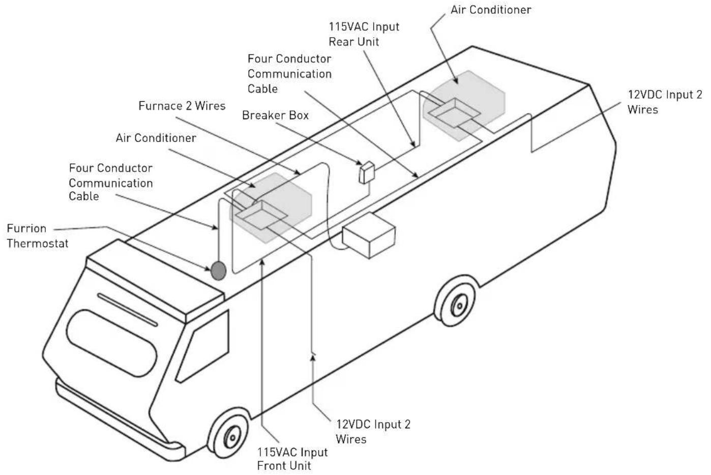
Multi Zone Wiring Diagram

natural_image
Abstract black geometric shapes on white background (no text or symbols)Furrion Innovation Center & Institute of Technology
- 52567 Independence Ct., Elkhart, IN 46514, USA - Toll free:1-800-789-3341
- Email: support@furrion.com
©2007-2020 Furrion Ltd. Furrion® and the Furrion logo are trademarks licensed for use by Furrion Ltd. and registered in the U.S. and other countries.
CN ZL201830175933.3 and other patents pending (FACR13SA-PS, FACR13SA-BL, FACR14SA-PS, FACR14SA-BL, FACR15SA-PS, FACR15SA-BL, FACT12LA-PS, FACT12SA-PS)
www.furrion.com
Single Zone Premium Wall Thermostat
Instruction Manual
Model: FACW12PA-BL

Welcome
Thank you for purchasing this Furrion® Single Zone Premium Wall Thermostat. Before operating your new product, please read these instructions carefully. This instruction manual contains information for safe use, installation and maintenance of the product.
Please keep this instruction manual in a safe place for future reference. This will ensure safe use and reduce the risk of injury. Be sure to pass on this manual to new owners of this product.
The manufacturer does not accept responsibility for any damages due to not observing these instructions.
If you have any further questions regarding our products, please contact us at support@furrion.com
Contents
Welcome....1
Contents 2
About your Thermostat....3
Product Features....3
Control Buttons....3
LCD Icons 4
Installation 5
What's in the Box 5
Thermostat Installation 5
Operation....7
Turn On/Off the Thermostat....7
Temperature Format....7
Operation Mode....7
Set the Temperature 9
Set the Fan Speed 10
Mood Light....10
Sleep Mode....10
Special Features....11
Auto Fan 11
Compressor Time Delay....11
LCD Error Code 11
Wiring Diagram 12
Specifications 13
Warranty....14
About your Thermostat
Product Features
Your Single Zone LCD thermostat is equipped with a liquid crystal display (LCD) to indicate the temperature set-point in Fahrenheit(°F)/Centigrade(°C) and fan speed. It is also equipped with LCD to indicate the system available operation modes.
NOTE: The available operation modes will be different depending on the system installed in your RV.
• Liquid Crystal Display and Mode Indicators
- Auto Fan
• Room Temperature Display
• Fahrenheit(°F)/Centigrade(°C) Display
- Sleep Mode
- LED Mood Light
Control Buttons
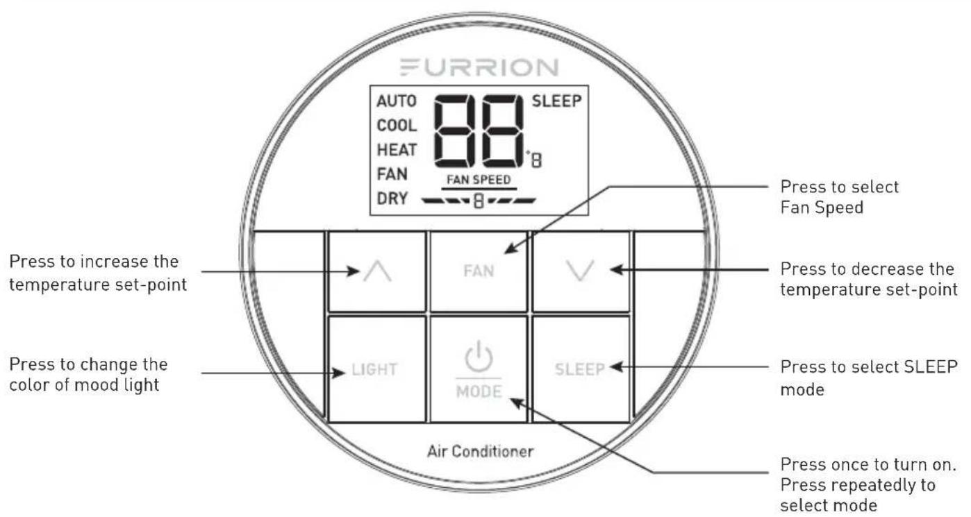
About your Thermostat
LCD Icons

Installation
What's in the Box
Make sure you have all the following items included in the packaging. If any item is damaged or missing, contact your dealer.
-Thermostat x 1
-Instruction Manual x 1
-Warranty Card x 1
-Self-tapping Screw x 2
Thermostat Installation
- Select a suitable location that is not under direct influence from light, sun or other heat sources.
- Rotate the thermostat cover counterclockwise and pull out the base plate. (Fig. 1)
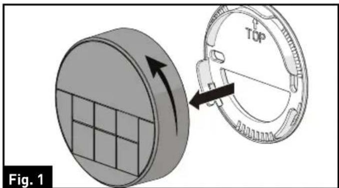
- Use the base plate as a template and drill a hole on the vehicle wall. Extend the four wire cables from the cutout area. Refer to the cable tag label for each cable definition. (Fig. 2)

- Fix the base plate on the wall using 2 screws. (Fig. 3)
NOTE: Make sure the base plate is not covering the hole and squeezing the thermostat cables.

Installation
- Connect the cables to thermostat. Rotate the thermostat clockwise until it clips into place. (Fig. 4 and Fig. 5)
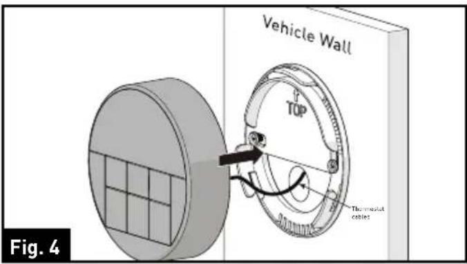

Operation
Your Furrion wall thermostat has been preprogrammed with factory default settings. Review the settings below and adjust to your comfort level.
| FACTORY DEFAULT SETTINGS | |
| HEATING 68°F / 20°C | |
| COOLING 72°F / 22°C | |
| FAN SPEED AUTO | |
| MODE AUTO | |
| FURNACE DIFFERENTIAL 2°F | |
Turn On/Off the Thermostat
To turn On
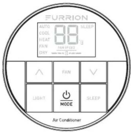
Press and hold the button for 3 seconds to turn on the thermostat. The thermostat LCD will be illuminated and the factory settings will be displayed on the LCD for first time use.
NOTE: The LCD will display the last setting if you have changed the parameters.
To turn Off
Press and hold button for 3 seconds to turn off the thermostat.
Only the current room temperature will be displayed on the LCD.
Temperature Format

Simultaneously press both and ∨ buttons for 3 seconds to toggle the temperature format between Centigrade and Fahrenheit.
NOTE: °F indicates Fahrenheit and °C indicates Centigrade.
Operation Mode
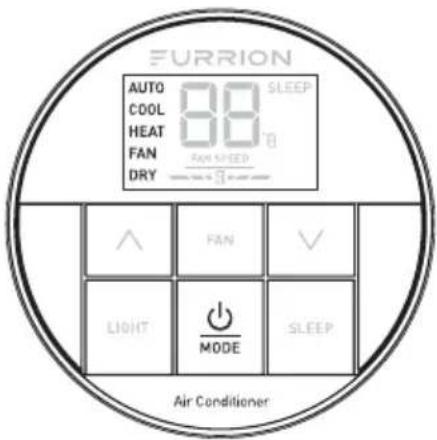
After the thermostat is turned on, press the button repeatedly to toggle through the available modes. The activated mode icon and temperature set-point will be displayed on the LCD. The thermostat will transmit the last selected operation mode command to the control box after 2 seconds without any operation.
Depending on the system installed, there
Operation
are 5 available modes (AUTO, COOL, HEAT, FAN and DRY) for you to select. See the following tables for detailed information of each mode.
NOTE: The HEAT mode is only available after the furnace is enabled.
AUTO MODE
- The system will changeover between COOL and HEAT mode according to the room temperature. For example, when the room temperature is below 68°F (20°C), the system will operate in HEAT mode. In contrast, when the room temperature is above 77°F (25°C), the system will operate in COOL mode. It operates the Dry Mode in comfort temperature between 68°F (20°C) to 77°F (25°C).
- The AUTO icon and the current temperature set-point displays on the LCD.
COOL MODE
- The system will cycle the compressor on and off based on the room temperature and the temperature set-point.
- The fan will be turned on after the compressor is running.
- There are 4 fan speed selections in this mode.
| Low | The fan operates continuously at low speed and theFAN SPEEDicon displays on the LCD. |
| Med | The fan operates continuously at medium speed and theFAN SPEEDicon displays on the LCD. |
| High | The fan operates continuously at high speed and theFAN SPEEDicon displays on the LCD. |
| Auto | The fan speed varies depending on the difference between the temperature set-point and room temperature. TheFAN SPEEDicon displays on the LCD. |
Operation
HEAT MODE
NOTE: The HEAT mode is only available when the furnace is enabled.
- The system will cycle the furnace on and off based on the room temperature and temperature set-point.
- There are 4 fan speed selections in this mode.
- The fan speed selections only apply to the rooftop fan that is part of the Air Conditioner. The fan speed selection does not change the fan speed of the furnace.
| Low | The fan operates continuously at low speed and theFAN SPEEDicon displays on the LCD. |
| Med | The fan operates continuously at medium speed and theFAN SPEEDicon displays on the LCD. |
| High | The fan operates continuously at high speed and theFAN SPEEDicon displays on the LCD. |
| Auto | The fan speed varies depending on the difference between the temperature set-point and room temperature. TheFAN SPEEDicon displays on the LCD. |
| OFF | The fan is off. TheFAN SPEEDicon displays on the LCD. |
FAN MODE
- The temperature set-point is not available.
- There are 3 fan speed selections in this mode.
| Low | The fan operates continuously at low speed and theFAN SPEEDicon displays on the LCD. |
| Med | The fan operates continuously at medium speed and theFAN SPEEDicon displays on the LCD. |
| High | The fan operates continuously at high speed and theFAN SPEEDicon displays on the LCD. |
DRY MODE
- Compressor runs continuously when room temperature is higher than set-point.
- Compressor cycles ON for 10 minutes and OFF for 6 minutes when room temperature is lower than set-point.
- The fan speed runs continuously at low speed.
Set the Temperature

The temperature set-point ranges from
Operation
60^ 86^ (16°C\~30°C).
- Press ⏻ button to toggle to your desired mode.
- Press or button to increase or decrease the temperature set-point to your comfort level.
NOTE: The temperature set-point is not available in FAN mode.
Set the Fan Speed
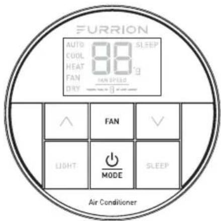
- Press ⬆ button repeatedly to toggle to your desired mode.
- Press FAN button to select AUTO, HIGH, MEDIUM or LOW fan speed.
NOTE: The fan speed selection is not available in DRY mode.
Mood Light

The thermostat is designed with 7
predefined colors of LED light in the air distribution box.
- Press LIGHT button on the thermostat to turn on the mood light.
- Press LIGHT button to toggle to your desired mood light.
- To turn off the mood light, press LIGHT button repeatedly until the mood light turns off.
Sleep Mode

- Press SLEEP button on the thermostat to turn on SLEEP mode. The SLEEP icon and the current temperature set-point will be displayed on the LCD.
- After meeting desired temperature. In Cool Mode:
The temperature set-point will increase 2^ F after running for 1 hour and increase 2^ F after running for 2 hours, then the fan speed will be fixed to LOW speed.
In Heat mode:
The temperature set-point will decrease 2^ F after running for 1 hour and decrease 2^ F after running for 2 hours, then the fan speed will be fixed to LOW speed.
Special Features
Auto Fan
When the auto fan mode is selected, the fan speed will vary depending on the temperature difference between the temperature set-point and the room temperature.
| Temperature Difference | Fan Speed |
| >3°F | The fan operates on High level |
| >1°F | The fan operates on Med level |
| <-1°F | The fan operates on Low level |
Compressor Time Delay
A time delay of approximately three minutes occurs any time the compressor is required to begin the cooling cycle.
NOTE: The time delay occurs automatically after a mode is selected or a power event occurs to ensure pressure in the compressor is equalized appropriately, to prevent damage.
Power Interruption
In the event the power to the air conditioner or controller is interrupted, the system will restart automatically with the last status and operational parameter set-points once the power is restored.
LCD Error Code
The following error code will be displayed on the LCD when the system detects one of the following faults has occurred.
| LCD Error Code | |
| E1 | Indoor temperature sensor out of order. System will shut down. |
| E2 | Evaporator temperature sensor out of order. System will shut down. |
| E3 | Loss of communication between the thermostat and control box. System will shut down. |
| E4 | Condenser temperature sensor out of order. System will shut down. |
| E5 | Outdoor temperature sensor out of order. System will shut down. |
| L0 | Insufficient low level of +12V power supply. System will shut down. |
Wiring Diagram

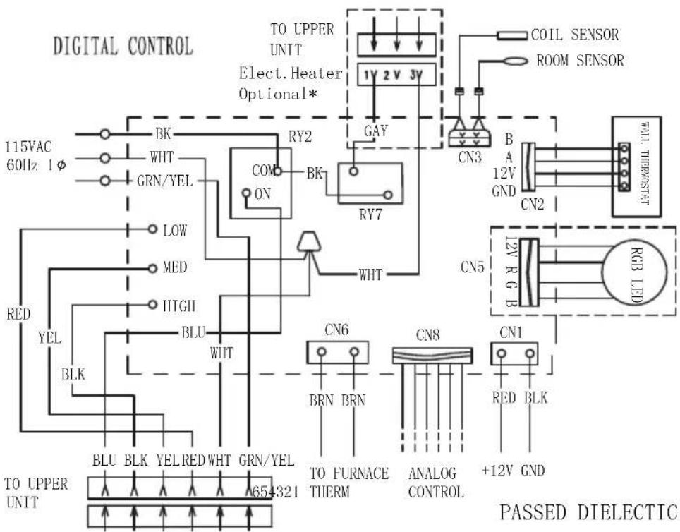
flowchart
graph TD
    A["TO UPPER UNIT 654321"] --> B["BLU BLK YEL RED WHT GRN/YEL"]
    A --> C["BLK BLK"]
    A --> D["YEL BLU"]
    A --> E["RED YEL"]
    A --> F["LOW MED"]
    A --> G["GRN/YEL"]
    H["COIL SENSOR ROOM SENSOR"] --> I["1V 2V 3V"]
    J["COIL SENSOR"] --> K["CN3"]
    L["FALL THERMOST"] --> M["B A 12V GND"]
    N["RGB LED"] --> O["CN5"]
    P["ANALOG CONTROL"] --> Q["CN8"]
    R["RED BLK"] --> S["CN1"]
    T["TO FURNACE THERM"] --> U["CN6"]
    V["GAY"] --> W["RY7"]
    X["WHT"] --> Y["BY2"]
    Z["COM ON"] --> AA["BY7"]
    AB["BRN"] --> AC["CN6"]
    AD["BRN"] --> AE["CN8"]
    AF["+12V GND"] --> AG["CN1"]
Specifications
| DC Input Power DC 12V | |
| Power Consumption <0.5W | |
| Baud Rate 9600bps | |
| Dimension 3 x 3 x ^15/16 " (75 x 75 x 22.5mm) | |
| Weight 0.06kg | |
| LCD Viewing angle 12 o'clock | |
Warranty
FURRION WARRANTS FOR A PERIOD OF 1 YEAR FROM DATE OF RETAIL PURCHASE BY THE ORIGINAL END-USE PURCHASER, THAT THIS PRODUCT, WHEN DELIVERED TO YOU IN NEW CONDITION, IN ORIGINAL PACKAGING, FROM A FURRION AUTHORIZED RESELLER AND USED IN NORMAL CONDITIONS, IS FREE FROM ANY DEFECTS IN MANUFACTURING, MATERIALS, AND WORKMANSHIP. IN CASE OF SUCH DEFECT, FURRION SHALL REPLACE OR REPAIR THE PRODUCT AT NO CHARGE TO YOU. THIS WARRANTY DOES NOT COVER: PRODUCTS WHERE THE ORIGINAL SERIAL NUMBERS HAVE BEEN REMOVED, ALTERED OR CANNOT READILY BE DETERMINED; DAMAGE OR LOSS CAUSED BY ACCIDENT, MISUSE, ABUSE, NEGLECT, PRODUCT MODIFICATION, FAILURE TO FOLLOW INSTRUCTIONS IN INSTRUCTION MANUAL, COMMERCIAL OR INDUSTRIAL USE; DAMAGE OR LOSS CAUSED TO THE DECORATIVE SURFACE OF PRODUCT; TO ANY DATA, SOFTWARE OR INFORMATION; AND NORMAL WEAR AND TEAR. THIS WARRANTY ONLY PROTECTS THE ORIGINAL END-USER ("YOU") AND IS NOT TRANSFERABLE; ANY ATTEMPT TO TRANSFER THIS WARRANTY SHALL MAKE IT IMMEDIATELY VOID. THIS WARRANTY IS ONLY VALID IN THE COUNTRY OF PURCHASE.
THIS WARRANTY AND REMEDIES SET FORTH ABOVE ARE EXCLUSIVE AND IN LIEU OF ALL OTHER WARRANTIES, REMEDIES AND CONDITIONS, WHETHER ORAL OR WRITTEN, EXPRESS OR IMPLIED. FURRION SPECIFICALLY DISCLAIMS ANY AND ALL IMPLIED WARRANTIES, INCLUDING, WITHOUT LIMITATION, WARRANTIES OF MERCHANTABILITY AND FITNESS FOR A PARTICULAR PURPOSE. IF FURRION CANNOT LAWFULLY DISCLAIM IMPLIED WARRANTIES UNDER THIS LIMITED WARRANTY, ALL SUCH WARRANTIES, INCLUDING WARRANTIES OF MERCHANTABILITY AND FITNESS FOR A PARTICULAR PURPOSE ARE LIMITED TO THE DURATION OF THIS WARRANTY.
No Furrion reseller, agent, or employee is authorized to make any modification, extension, or addition to this warranty.
Warranty
FURRION IS NOT RESPONSIBLE FOR DIRECT, INDIRECT, SPECIAL, INCIDENTAL OR CONSEQUENTIAL DAMAGES RESULTING FROM ANY BREACH OF WARRANTY OR CONDITION, OR UNDER ANY OTHER LEGAL THEORY, INCLUDING BUT NOT LIMITED TO LOST PROFITS, DOWNTIME, GOODWILL, DAMAGE TO OR REPLACEMENT OF ANY EQUIPMENT OR PROPERTY, ANY COSTS OF RECOVERING, REPROGRAMMING, OR REPRODUCING ANY PROGRAM OR DATA STORED IN OR USED WITH FURRION PRODUCTS. FURRION'S TOTAL LIABILITY IS LIMITED TO THE REPAIR OR REPLACEMENT OF THIS PRODUCT PURSUANT TO THE TERMS OF THIS WARRANTY. SOME STATES DO NOT ALLOW THE EXCLUSION OR LIMITATION OF INCIDENTAL OR CONSEQUENTIAL DAMAGES OR EXCLUSIONS OR LIMITATIONS ON THE DURATION OF IMPLIED WARRANTIES OR CONDITIONS, SO THE ABOVE LIMITATIONS OR EXCLUSIONS MAY NOT APPLY TO YOU. THIS WARRANTY GIVES YOU SPECIFIC LEGAL RIGHTS, AND YOU MAY ALSO HAVE OTHER RIGHTS THAT VARY BY STATE OR (WHERE APPLICABLE IN THE COUNTRIES WHERE FURRION HAS NON-US/CANADIAN AUTHORIZED DEALERS) COUNTRY. NO ACTION OR CLAIM TO ENFORCE THIS WARRANTY SHALL BE COMMENCED AFTER THE EXPIRATION OF THE WARRANTY PERIOD.
Keep your receipt, delivery slip, or other appropriate payment record to establish the warranty period. Service under this warranty must be obtained by contacting Furrion at warranty@furrion.com
Product features or specifications as described or illustrated are subject to change without notice.
FURRION
Furrion Innovation Center & Institute of Technology
● 52567 Independence Ct., Elkhart, IN 46514, USA ● Toll free:1-888-354-5792
- Email: support@furrion.com
©2007-2018 Furrion Ltd. Furrion® and the Furrion logo are trademarks licensed for use by Furrion Ltd. and registered in the U.S. and other countries.
FURRION.COM
- Contents
- Contents....1
- Important Safety Instructions....2
- Before Installing 4
- Installation 10
- Cleaning and Maintenance ....16
- Troubleshooting....17
- Specifications....18
- Wiring Diagram....19
- Important Safety Instructions
- USA:
- Canada:
- Handling the Device
- WARNING
- CAUTION
- Handling Electrical Cables
- Before Installing
- What's in the Box
- Choosing Proper Location for the Air Conditioner
- Existing Roof Vent Opening
- New Opening
- After the Location Has Been Selected:
- Roof Preparation
- Fire/Electric Shock Hazard
- Roof Thickness
- Installing in an Existing
- Opening
- Making a New Opening
- Air Distribution Duct Sizing and Design
- TOP VIEW (BACK OF RV)
- Air Distribution System Installation
- Laying the Connecting Cables
- ! DANGER
- Electrical Shock Hazard
- Installation
- Installing the Rooftop Unit
- Installing the Wall Thermostat (model: FACW12SA-BL/FACW12PA-BL/FACW12ZA-BL, sold separately)
- Installing the Air Distribution Box (for FACT12LA-PS/FACT12LA- BL/FACT12SA-PS/ FACT12SA-BL models only, same for both ducted and non-ducted models, sold separately)
- Cleaning and Maintenance
- To Clean the Filter
- To Replace the Filter
- Troubleshooting
- Specifications
- Wiring Diagram
- Multi Zone Wiring Diagram
- Furrion Innovation Center & Institute of Technology
- Single Zone Premium Wall Thermostat
- Welcome
- Welcome....1
- Contents 2
- About your Thermostat....3
- Installation 5
- Operation....7
- Special Features....11
- Wiring Diagram 12
- Specifications 13
- Warranty....14
- About your Thermostat
- Product Features
- Control Buttons
- LCD Icons
- Thermostat Installation
- Operation
- Turn On/Off the Thermostat
- To turn On
- To turn Off
- Temperature Format
- Operation Mode
- AUTO MODE
- COOL MODE
- HEAT MODE
- FAN MODE
- DRY MODE
- Set the Temperature
- Set the Fan Speed
- Mood Light
- Sleep Mode
- In Heat mode:
- Special Features
- Auto Fan
- Compressor Time Delay
- Power Interruption
- LCD Error Code
- Warranty
- FURRION
Brand : Furrion
Model : EACEPE4
Category : Air conditioner