
TVS-3000 - VCR DataVideo - Free user manual and instructions
Find the device manual for free TVS-3000 DataVideo in PDF.


| Product Type | 4K AR 3D Tracking Virtual Studio System (VCR/Production Switcher) |
| Dimensions (TVS-3000) | 480 x 470 x 178 mm |
| Weight (TVS-3000) | 13.6 kg |
| Power Supply (TVS-3000) | AC 100-240V, 750W |
| Remote Control Panel (RMC-285) Weight | 2 kg |
| Remote Control Panel Dimensions | 44 x 24.5 x 9.5 cm |
| Remote Control Panel Power | DC 12V, 3.6W |
| Video Inputs | 4K Mode: 6G-SDI x2 or 12G-SDI x1; HD Mode: 3G-SDI x3 |
| Video Outputs | 4K Mode: HDMI 2.0 x1; HD Mode: 3G-SDI x1 + HDMI x1; IP: NDI, RTMP(S), TS, SRT |
| Audio Inputs | Mini Phone Jack x1, Line-in x1, SDI embedded audio x3 |
| Recording Formats | Lossless 4:2:2 (.avi), H.265 (.mov), H.264 (.mp4/.wmv), MPEG-2 (.ts/.mxf) |
| Live Streaming Protocols | TS over UDP/TCP, RTMP/RTMPS, SRT (Input/Output), NDI |
| PTZ Control Protocols | CGI, VISCA, ONVIF, Pelco D/P, PSIA, VISCA over IP; RS-232/422/485 via USB |
| Hard Disk Capacity | 4TB HDD + 500GB SSD |
| Operating Temperature | 0 to 40 °C |
| Downstream Keys | 3 Global overlays + 2 per channel (8 channels) = 16 keyers |
| Chroma Keyer | Built-in with 4 color selection, eraser, alpha adjustment, edge softening |
| Virtual Studio | 3D virtual scenes with 360° tracking (HTC Tracker), up to 6 virtual cameras |
| Macro Recording/Playback | Up to 16 steps per macro, with snapshot, loop, sequential play |
| Cleaning & Maintenance | Use a damp cloth; do not use liquid or aerosol cleaners; unplug before cleaning. |
| Safety Warnings | Do not use near water, do not block ventilation, use only specified power source, refer servicing to qualified personnel. |
| Warranty | Standard 1 year; extended to 3 years if registered within 30 days of purchase. |
Frequently Asked Questions - TVS-3000 DataVideo
User questions about TVS-3000 DataVideo
0 question about this device. Answer the ones you know or ask your own.
Ask a new question about this device
Download the instructions for your VCR in PDF format for free! Find your manual TVS-3000 - DataVideo and take your electronic device back in hand. On this page are published all the documents necessary for the use of your device. TVS-3000 by DataVideo.
USER MANUAL TVS-3000 DataVideo
WARNINGS AND PRECAUTIONS .... 4
WARRANTY....5
STANDARD WARRANTY 5
THREE YEAR WARRANTY 5
DISPOSAL....5
CHAPTER 1 INTRODUCTION....7
1.1 FEATURES....7
1.2 SYSTEM REQUIREMENTS....7
CHAPTER 2 SYSTEM DIAGRAM....8
CHAPTER 3. LAYOUT OF THE MAIN INTERFACE ...... 9
3.1 CONTROL AND STATUS BAR 9
3.2 FUNCTION BAR 9
3.3 PREVIEW WINDOWS FOR SWITCHING CHANNEL....10
3.4 PREVIEW & PROGRAM WINDOWS.... 11
3.5 SWITCHING BUTTONS.... 11
4.4.1 Main Interface of the Graphic & Text Combination Editor....27
4.4.2 Editing for Multiple Layers Graphic and Text Combinations.... 31
4.4.3 Apply the CG Package Content from Channel to the BCD Windows.... 35
4.4.4 Create a PIP with more than 4 Live-Scenes by the the Category Layer 38
4.4.5 How to Create and Use a Captions' Subtitle Template.... 38
4.5 DSK LAYER AND KEY LAYER 40
4.5.1 Add material to the DSK Layer/KEY Layer 41
4.5.2 Showing/Hiding of the Contents for the DSK Layer/KEY Layer 42
4.5.3 Location and Size Adjustment for DSK Layer/KEY Layer 42
4.5.4 Use DSK Layer/KEY Layer to add the PREVIEW/PROGRAM Keyer Signals 43
4.6 CHROMAKEY, BEAUTY AND VERTICAL SCENES 44
4.6.1 Chromakey Settings 44
4.6.2 Beauty 48
4.6.3 Load Content into the Virtual Scenes 49
4.6.4 The Adjustment for Virtual Objects and Position of Virtual Camera Lens 50
4.7 AUDIO MIXER....52
4.8 STREAMING/RECORDING....54
4.8.1 Streaming....54
4.8.2 Video Recording to Local Hard Disk....54
4.9 CAPTURE CARD SETTINGS AND FILE RELATED SETTINGS 56
4.9.1 Safe Frame....56
4.9.2 Capture Card Settings 56
4.9.3 Project Files for the TVS-3000....56
4.10 MULTIVIEW 57
4.11 PTZ CONTROL 58
4.12 AMF FORMAT 60
4.13 RECORDING AND PLAYING OF MACROS 61
4.13.1 Recording for Macros....61
4.14 TRACKING, VIRTUAL STUDIO AND AR FUNCTIONS 63
4.14.1 Installation of the HTC Tracker and the Camera 63
4.14.2 Data Test of the Camera Lens 65
4.14.3 TVS-3000 HTC Tracker Test and Adjustment Reminders....67
4.14.4 Camera Tracking and Binding 70
4.14.5 Position Adjustment....71
4.14.6 Binding of the AR Object 72
CHAPTER 5 HOW TO SET THE BLACKMAGIC DESKTOP VIDEO SETUP....74
5.1 VIDEO OUTPUT 75
5.2 CONNECTORS MAPPING OF THE DECKLINK 8K PRO....76
5.3 DECKLINK 8K PRO CONNECTORS AND CORRESPONDING SDI NUMBERS ON THE REAR PANEL OF THE TVS-3000....77
CHAPTER 6 GRAPHIC CARD DE-INTERLACE AND GRAPHIC CARD MEMORY USAGE ISSUES....78
6.1 HOW TO SET THE GRAPHIC CARD DE-INTERLANCE SETTINGS 78
6.2 HOW TO SOLVE THE GRAPHIC CARD MEMORY USAGE ISSUE 79
6.3 IMPORTANT NOTICE WHEN CONNECTING THE TVS-3000 TO AN EXTERNAL CONNECTED MONITOR 80
CHAPTER 7 HOTKEYS LIST 81
CHAPTER 8 RMC-285 TVS-3000 REMOTE CONTROL PANEL 82
8.1 INTRODUCTION OF THE RMC-285 REMOTE CONTROL PANEL 82
8.2 FEATURES....82
8.3 CONTROL PANEL....82
8.4 REAR PANEL 83
8.5 LED COLOR AND SITUATION FOR THE CONTROL PANEL BUTTONS....83
CHAPTER 9 FREQUENTLY-ASKED QUESTIONS....87
CHAPTER 10 PRODUCT SPECIFICATIONS....91
SERVICE AND SUPPORT....96
Disclaimer of Product and Services
The information offered in this instruction manual is intended as a guide only. At all times, Datavideo Technologies will try to give correct, complete and suitable information. However, Datavideo Technologies cannot exclude that some information in this manual, from time to time, may not be correct or may be incomplete. This manual may contain typing errors, omissions or incorrect information. Datavideo Technologies always recommend that you double check the information in this document for accuracy before making any purchase decision or using the product. Datavideo Technologies is not responsible for any omissions or errors, or for any subsequent loss or damage caused by using the information contained within this manual. Further advice on the content of this manual or on the product can be obtained by contacting your local Datavideo Office or dealer.
FCC Compliance Statement
This device complies with part 15 of the FCC rules. Operation is subject to the following two conditions:
1) This device may not cause harmful interference, and
2) This device must accept any interference received, including interference that may cause undesired operation.
Warnings and Precautions
- Read all of these warnings and save them for later reference.
- Follow all warnings and instructions marked on this unit.
- Unplug this unit from the wall outlet before cleaning. Do not use liquid or aerosol cleaners. Use a damp cloth for cleaning.
- Do not use this unit in or near water.
- Do not place this unit on an unstable cart, stand, or table. The unit may fall, causing serious damage.
- Slots and openings on the cabinet top, back, and bottom are provided for ventilation. To ensure safe and reliable operation of this unit, and to protect it from overheating, do not block or cover these openings. Do not place this unit on a bed, sofa, rug, or similar surface, as the ventilation openings on the bottom of the cabinet will be blocked. This unit should never be placed near or over a heat register or radiator. This unit should not be placed in a built-in installation unless proper ventilation is provided.
- This product should only be operated from the type of power source indicated on the marking label of the AC adapter. If you are not sure of the type of power available, consult your Datavideo dealer or your local power company.
- Do not allow anything to rest on the power cord. Do not locate this unit where the power cord will be walked on, rolled over, or otherwise stressed.
- If an extension cord must be used with this unit, make sure that the total of the ampere ratings on the products plugged into the extension cord do not exceed the extension cord rating.
- Make sure that the total amperes of all the units that are plugged into a single wall outlet do not exceed 15 amperes.
- Never push objects of any kind into this unit through the cabinet ventilation slots, as they may touch dangerous voltage points or short out parts that could result in risk of fire or electric shock. Never spill liquid of any kind onto or into this unit.
- Except as specifically explained elsewhere in this manual, do not attempt to service this product yourself. Opening or removing covers may expose you to dangerous voltage points or other risks, and will void your warranty. Refer all service issues to qualified service personnel.
- Unplug this product from the wall outlet and refer to qualified service personnel under the following conditions:
a. When the power cord is damaged or frayed;
b. When liquid has spilled into the unit;
c. When the product has been exposed to rain or water;
d. When the product does not operate normally under normal operating conditions. Adjust only those controls that are covered by the operating instructions in this manual; improper adjustment of other controls may result in damage to the unit and may often require extensive work by a qualified technician to restore the unit to normal operation;
e. When the product has been dropped or the cabinet has been damaged;
f. When the product exhibits a distinct change in performance, indicating a need for service.

Warranty
Standard Warranty
- Datavideo equipment is guaranteed against any manufacturing defects for one year from the date of purchase.
- The original purchase invoice or other documentary evidence should be supplied at the time of any request for repair under warranty.
- The product warranty period beings on the purchase date. If the purchase date is unknown, the product warranty period begins on the thirtieth day after shipment from a Datavideo office.
- All non-Datavideo manufactured products (product without Datavideo logo) have only one year warranty from the date of purchase.
- Damage caused by accident, misuse, unauthorized repairs, sand, grit or water is not covered under warranty.
• Viruses and malware infections on the computer systems are not covered under warranty. - Any errors that are caused by unauthorized third-party software installations, which are not required by our computer systems, are not covered under warranty.
- All mail or transportation costs including insurance are at the expense of the owner.
- All other claims of any nature are not covered.
- All accessories including headphones, cables, batteries, metal parts, housing, cable reel and consumable parts are not covered under warranty.
- Warranty only valid in the country or region of purchase.
- Your statutory rights are not affected.
Three Year Warranty
- All Datavideo products purchased after July 1st, 2017 qualify for a free two years extension to the standard warranty, providing the product is registered with Datavideo within 30 days of purchase.

- Certain parts with limited lifetime expectancy such as LCD panels, DVD drives, Hard Drive, Solid State Drive, SD Card, USB Thumb Drive, Lighting, Non-PCIe Card and third party provided PC components are covered for 1 year.
- The three-year warranty must be registered on Datavideo's official website or with your local Datavideo office or one of its authorized distributors within 30 days of purchase.
Disposal

natural_image
Symbol of a trash bin crossed out by two crossed lines, no text or labels presentFor EU Customers only - WEEE Marking
This symbol on the product or on its packaging indicates that this product must not be disposed of with your other household waste. Instead, it is your responsibility to dispose of your waste equipment by handing it over to a designated collection point for the recycling of waste electrical and electronic equipment. The separate collection and recycling of your waste equipment at the time of disposal will help to conserve natural resources
and ensure that it is recycled in a manner that protects human health and the environment. For more information about where you can drop off your waste equipment for recycling, please contact your local city office, your household waste disposal service or the shop where you purchased the product.
CE
CE Marking is the symbol as shown on the left of this page. The letters "CE" are the abbreviation of French phrase "Conformité Européenne" which literally means "European Conformity". The term initially used was "EC Mark" and it was officially replaced by "CE Marking" in the Directive 93/68/EEC in 1993. "CE Marking" is now used in all EU official documents.
Chapter 1 Introduction
The TVS-3000 is a real-time production solution which is based on switcher functions. TVS-3000 provides users the powerful computing power for achieving real-time transition effects, image & text combination, professional live character generator system, virtual scenes, fast motion and slow motion replay, streaming and recording simultaneously for production needs in different environments.
1.1 Features
● Supports up to 2 4K25/30P Video Signal Inputs
● Supports 3D Rocker Arm Tracking
● 3D Virtual Studio
● Supports 4 high resolution switching signals for standard setting and can be expanded for supporting up to 8 switching signals for optional.
● Supports up to 8 signals for high resolution ISO recording
● Supports H.264 Encoding for Live-Streaming
● Supports Broadcasting Grade Image & Text Editing
● Supports Built-in software-based Audio Mixer with fast motion and slow motion replay
● Supports NDI Format
1.2 System Requirements
If you purchase Datavideo's TVS-3000 3D Tracking VR/AR 4K Virtual Studio System, its hardware settings can assure the normal operation of the TVS-3000 software. For other situations, please purchase the system with the settings that are equal or above following table for normal operation of the TVS-3000 software.
| CPU | Intel Core i7 3.5GHz |
| GPU | Nvidia RTX2070 8GB |
| Memory | 16GB DDR4 2133MHz |
| SSD for system | 500 GB SSD |
| HDD for material | 3.5”HDD, 4TB/7200RPM |
| OS | Windows 10 64bit |
Chapter 2 System Diagram
1. 4K Mode
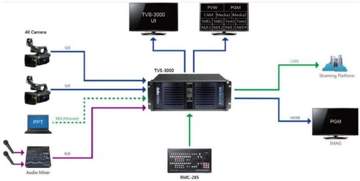
flowchart
graph TD
    A["TVS-3000 UI"] -->|SDI| B["TVS-3000"]
    C["4K Camera"] -->|SDI| B
    D["PPT"] -->|NDI (Ethernet)| B
    E["Audio Mixer"] -->|XLR| B
    F["PGM"] -->|HDMI| G["PGM"]
    H["Straming Platform"] -->|CAT6| B
    I["IMAG"] -->|HDMI| G
    J["TVS-3000"] --> K["ECOLED System"]
    K --> B
2. HD Mode
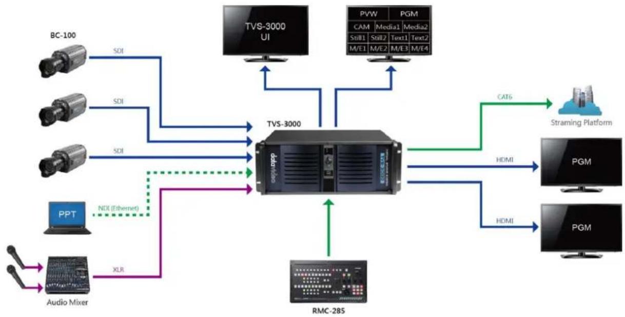
flowchart
graph TD
    A["BC-100"] -->|SDI| B["TVS-3000"]
    C["PPT"] -->|NDI (Ethernet)| B
    D["Audio Mixer"] -->|XLR| B
    E["TVS-3000 UI"] --> B
    F["PGM"] -->|CAT6| G["Straming Platform"]
    H["PGM"] -->|HDMI| G
    I["RMC-285"] -->|HDMI| G
    B -->|HDMI| G
    B -->|HDMI| G
    B -->|HDMI| G
    B -->|HDMI| G
    B -->|HDMI| G
    B -->|HDMI| G
    B -->|HDMI| G
    B -->|HDMI| G
    B -->|HDMI| G
    B -->|HDMI| G
    B -->|HDMI| G
    B <-->|SDI| B
Chapter 3. Layout of the Main Interface
The main interface of the Datavideo TVS-3000 software is shown as following diagram. The main interface provides users many functions including “Control and Status Bar”, “Function Bar”, “Preview Windows for Switching Channel”, “PREVIEW/PROGRAM Windows”, “Switching Buttons”, “Transition Effect”, “Overlay Sources for PGM Channel/Overlay Sources for Specific Channel”, “Virtual Camera Center”, “Location Changing Adjustment Panel”, “Lists of Different Types of Materials” and “Audio Mixer” for users. Please see following paragraphs for detailed introduction of the main interface of the TVS-3000.
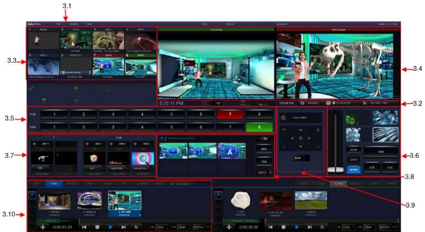
3.1 Control and Status Bar
Control and Status bar provides users the basic setting option. Users can save or open the engineering document from the “File” option. Moreover, users can set the basic PGM channel of the software, modify the streaming parameters, set the Multiview output format, set the PTZ control parameters and open the Image & Text Editor from the “Options” drop-down menu. The options in the drop-down menu will be updated according to the software version update. The “Control and Status Bar” is shown as following diagram.
3.2 Function Bar
The System Clock is located at the left side of the Function Bar and the Output Switch is located at the right side of the System Clock. When the Output Switch is pulled to the right side, the PGM channel will be activated and the PGM output will be started. The three bars which are located at the right side of the Output Switch are used for monitoring the hard disk
space, CPU/GPU workload and the status of the Internal RAM respectively. The three buttons which are located at the rightmost of the Function Bar are used to control screenshoot, video recording and video streaming. After those buttons are clicked, the corresponding operations will be activated and those buttons will be shown in blue, red and green respectively to show their operation status. The Function Bar is shown as following diagram.

3.3 Preview Windows for Switching Channel
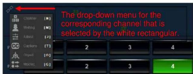
This area provides 8 preview windows for switching channels for users. Each switching channel can select a material/source list for the corresponding source of the channel. Each channel has its own "Channel", "Matting" and "Adjust" menu. After clicking the thumbnail of the desired channel that users want to adjust, the thumbnail of the selected channel will be surrounded
by a white rectangular. After that, users can click the link icon which is located at the bottom left side of the switching channel area to open the drop-down menu to adjust the conetent of the selected channel. The preview window of the switching channel is shown as following diagram.
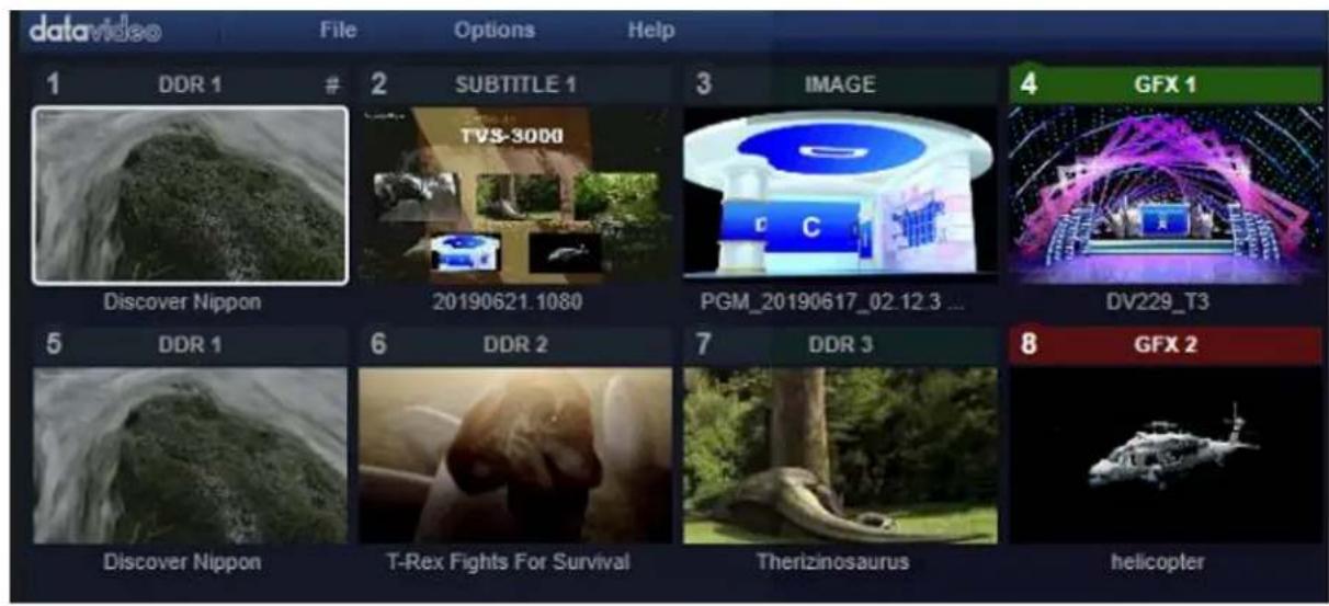
3.4 PREVIEW & PROGRAM WINDOWS
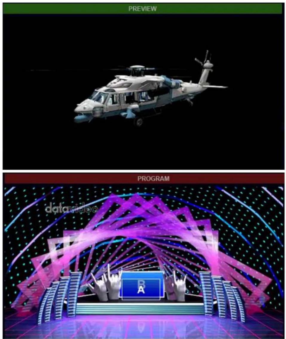
The content which is shown in the PREVIEW window is the content which is prepared to output to the PROGRAM window. The PROGRAM window will show the final content of the program that is capturing by the capture card or is streaming to stream platforms. The PREVIEW/PROGRAM windows are shown as following diagrams.
3.5 Switching Buttons
There are tow rows of the buttons including PGM and PWM. Please press the activated PGM channel button which is shown in red and then users can select any switching channel to transfer it to the PGM channel for output. If users click the PVM channel button which is shown in green, users can select any switching channel to transfer to the PVM channel for preview. The switching buttons are shown as following diagram.

3.6 Special Effects for Transition
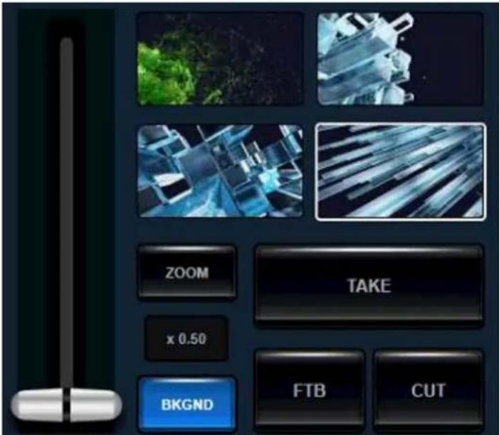
The area which is below the PROGRAM window is the special effects area for switching. There are four special effects switching buttons for loading up to 4 different special effects for switching. “Take”, “CUT” and “FTB” buttons and the virtual T-bar are also in this area. The virtual T-barr can control the moving of the virtual camera lens. The special effects switching area is shown as following diagram.
3.7 The DSK Overlay layer for PGM/Key Overlay Layer for a Specific Channel DSK Overlay Layer for PGM
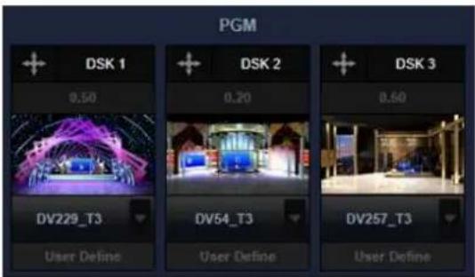
The Datavideo TVS-3000 provides three DSK Overlay layer for overlaying the characters or other layers on the surface of the output of the PGM channel. The contents which are added in these three DSK layers will be overlaid on the surface of the PGM signal. After loading the special effects for transition, the DSK layer will be shown and disappeared with the special effect. There is a red bar that will be shown to remind users that the content of this channel is activated and shown. The DSK Overlay layer is shown as following diagram.
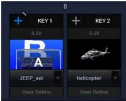
Key Overlay Layer for a Specific Channel
For each switching channel, users can assign two overlay layers for this specific channel only. This layer is different from the DSK Overlay layer for PGM, the content of the Key Overlay Layer will not be overlaid on the surface of the PGM permanently. When the content of this specific channel is switched out or is used to other Multiview picutres or virtual scenes, the key overlay layer will be kept on the content of this specific channel. The window for key overlay layer for a specific channel is shown as following diagram.
3.8 Virtual Camera Lens Area
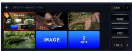
Users can set up to 6 different 3D or 2D Zoom In/Zoom Out scenes for each virtual scene or signal channel. Part of the thumbnail of each camera position or virtual scene will be kept in this virtual camera lens area. Users can double-click the camera position or click the “Take” button for smooth transiton. Users can also right-click the camera position or click the CUT button for direct transition. The virtual camera lens area is shown as following diagram.
3.9 Offset Adjustment Board
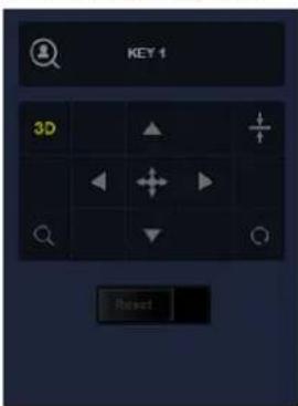
The Offset Adjustment Board is used for virtual camera lens adjustment, object adjustment of the virtual scene, location adjustment of the DSK/KEY layers. The characters which are shown above the arrow of the offset adjustment board will show the current selected item for adjustment. There is a “Reset” button which is located below the adjustment board. After the offset is adjusted, the button will be shown in white. Pull the “Reset” button to the right side will restore the adjusted item to its initial location. Users can not only click the up, down, left and right arrows but also can click the corresponding button and then drag the cursor of the mouse to adjust the location of the slected item. The Offset Adjustment Board is shown as following diagram.
3.10 List of Different Materials and Audio Mixer
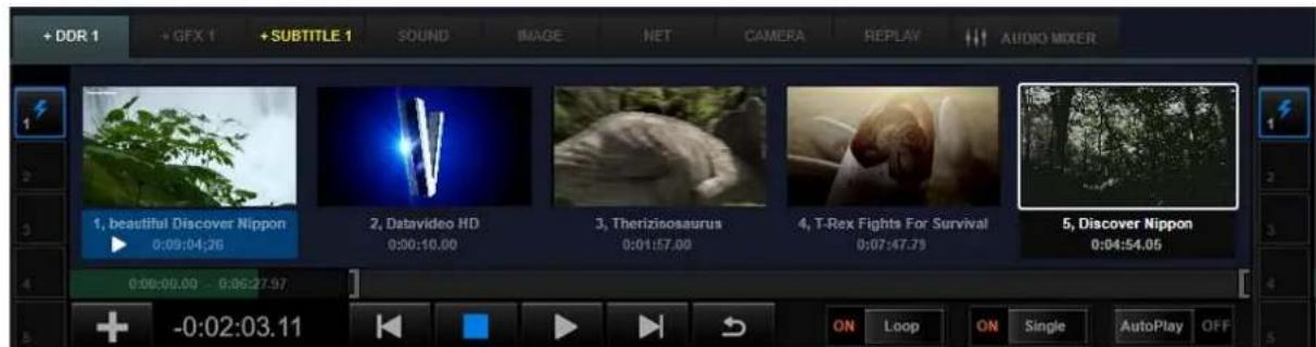
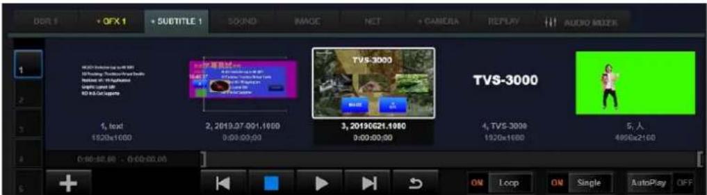
The Datavideo TVS-3000 can divide many local materials and signal sources into several categories. The tags for the lists of different materials are located on the top of the material lists for different material categories. Click the tag allows users to enter the list for each category. There are five material lists from No.1 to No.5 for the DDR/IMAGE/SUBTITLE categories. For other categories, they have one material list only. The way to add content into the material list is to click the Plus button on the bottom left side. The material list can be browsed by using the mouse wheel. For some material lists for saving the playable materials, there are playback progress bar and mark-in/mark-out progress bar which are located on the bottom left side of the material list window for users to jump to specific point for playing by a slider or to set the mark-in and mark-out points. There are some buttons including “Loop”, “Single” and “AutoPlay” which are located on the bottom right side for users to set the regulation for the playback. For the material lists which can be played in a specific order, there are five sub-playlists which are located on the left side of the material lists for users to edit five sub-playlists within one material category. The example for the material list for the “SUBTITLE” category is shown as following diagram.
Users can open the audio mixer interface by pressing the AUDIO MIXER tag, the audio situation for each corresponding switching channel will be shown on its corresponded audio mixer channel. Users can adjust the volume for each channel by the slider or can press the "MUTE", "SOLO" and "FOLLOW" buttons to turn on/turn off the playback regulation of the audio source for each corresponding channel. The slider which is located below the headphone icon on the left side of the first audio channel is used to control the volume of the monitoring output. The "AUX INPUT VOLUME" knob which is locatec on the right side is used to control the audio volume of the independent audio input source. The "OUTPUT VOLUME" knob is used to control the audio volume of the final program output. Users can press the "AUX" tag which is next to the "OUT" tag to open the audio mixer of independent audio input source. All of the activated independent audio input facilities which are connected to the TVS-3000 will be shown in this section. Users can adjust the volume of the audio input source and the regulation for the audio output in this section. The audio mixer is shown as following diagram.

Chapter 4 Operating Procedures
4.1 General Configuration
After entering the software interface, users can click the "General Configuration" from the "Option" drop-down menu for basic setting of the program production.
![Options Help General Configure User Language Activity Data Safe Frames Show Blackmagic Desktop Video Utility Streaming Settings PTZ Control Settings IP Video Settings Subtitle Editor SD 720 1080 4K Macros [R]](/content/2026/05/830674/images/905137f57eb0e04439e6e7dbea0a125e9a2d7cba00cd3b930738265b1757dffe.jpg)
Please open the "General Configuration" menu and then the window for the General Configuration settings will be show as following diagram.
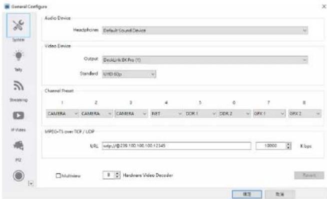
For the “Audio Device” and “Video Device”, users can click the “Headphones” and “Output” drop-down menus to show all of the audio and video output facilities that are connected to the TVS-3000. If users select the “Default Sound Device” option from the drop-down menu, the device which is set by the system control panel will be selected to be the audio output device.
The “Standard” drop-down menu allows users to determine the video output format of the program through the output card or the NDI output. If the setting of this option is changed, the TVS-3000 system will remind users to reboot the TVS-3000 to apply the new setting. The “Channel Preset” option allows users to preset the corresponding material/source categories for 8 channels in advance for creating the TVS-3000 file for the first time. Those presets can be changed directly from the software interface for future program production. The URL, port number and bit rate of the TS over TCP/UDP streaming can be set in MPEG-TS over TCP/UDP section. The URL for general RTMP streaming can be set from the “Streaming” option.
When there is a second display which is connected to the graphic card, users can open the multi-view signal from the second display by checking the “Multiview” checkbox.
The number of the “Hardware Video Decoder” determines the maximum number allowed of the videos for using the hardware encoding function of the graphic card simultaneously. If there are too many 4K videos are loaded for playing simultaneously, it will cause heavy loading for the video engine of the graphic card. Users can enter a lower number to solve this issue.
4.2 Add Signals
4.2.1 Material Categories
For the TVS-3000 software, users need to put different local materials and input signals that are needed for the program production into different material categories for management and allocation. Before production, users can add those materials into the lists of corresponding material categories. The material list is located on the bottom side of the whole TVS-3000 user interface. Users can show the corresponding material list by clicking the tag of each material list for further operation.

CAMERA: Users can add different camera signals, Input signals for NDI agreement and capturing signal for the second display panel into the material list of the "CAMERA" option. Please press the "CAMERA" tag and then click the "Plus" button which is located on the bottom left side of the material list window to open the drop-up menu. The drop-up menu will list all of the camera signals, input signals for NDI agreement and capturing signal for the second display panel automatically.
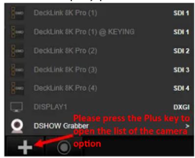
Each time when the plus button is pressed by users, the latest signal sources that can be used by users will be updated immediately. So, for the NDI signal and the signals for the newly-installed capturing card, users can press the "Plus" button to update the latest signals that can be used. The signals which are already added into the "CAMERA" category will not be shown again.
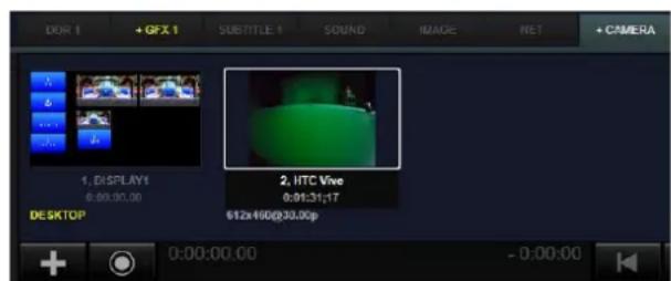
Users can press the needed item in the signal list and then the corresponding signals will be added into the list of the “CAMERA” category. The video format and the resolution of the input signal will be recognized automatically by the system and the input signal will be shown in thumbnail in a small window. The sequence number and the model name of the device for the input source will be shown below the window of the corresponding signal source.
Moreover, the time code of the input source device, resolution and the video format will be shown below the model name of the device.
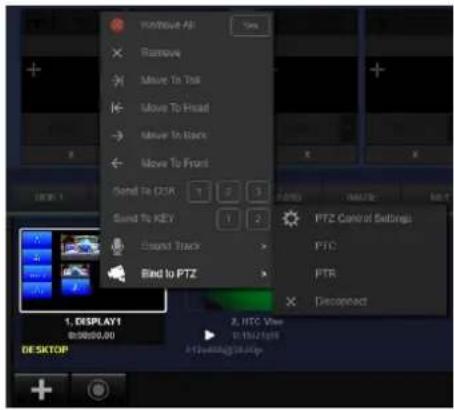
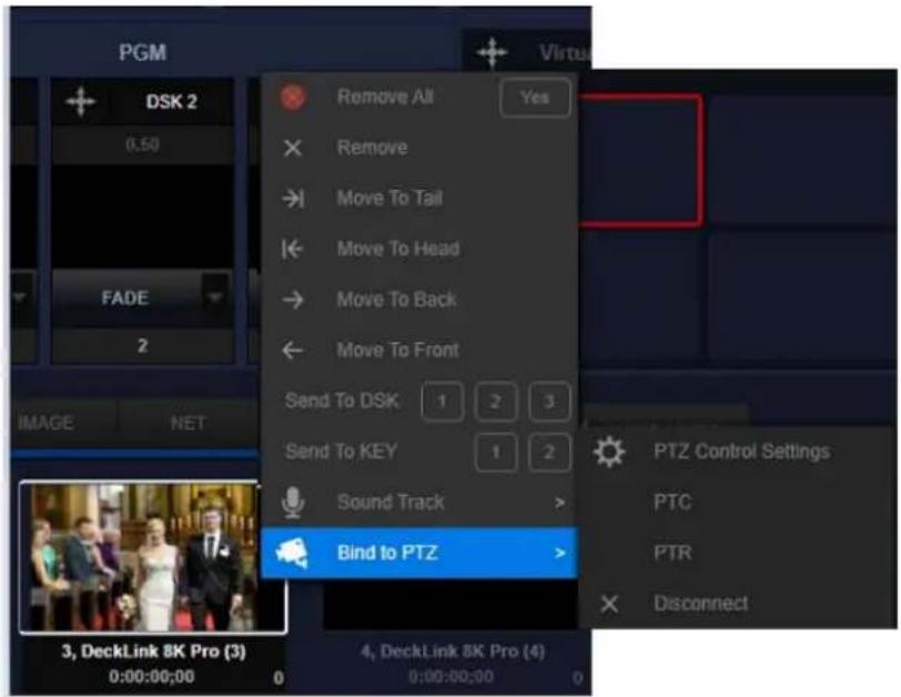
Users can right-click on the content of the thumbnail to show the menu for the single item operation in the category. For the items which are placed into the list of the “CAMERA” category, users can change their sequence, remove a specific signal source, send the signal to “DSK”, send the signal to “KEY” and bind this signal to the operating interface of a specific PTZ camera. For the source signal which is captured by the BMD capture card, users can click the “Recording” button to record the source signal to a local file for further application.
DDR 1/2/3: The local video files which need to be played can be added into the lists of the DDR 1/2/3 categories. Please press the "Plus" button on the bottom left side of the window of the list to select multiple video files and to load them into the list of one DDR category for one time.
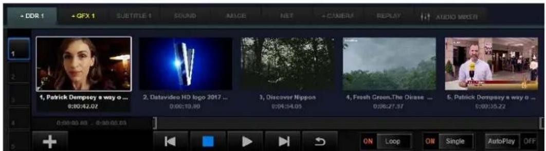
Users can scroll the wheel of the mouse to browse all of the items in the lists of the DDR1/2/3 categories. Users can start the video playback by double-clicking a specific video which is added into the list or clicking the video once and then pressing the play button. The selected video will be activated to be the current playback item of the DDR category and this video will be shown on the preview window of the switching channel which is assigned to be DDR1/2/3. Moreover, this selected DDR file will also be shown on the channel which that switching channel is quoted.
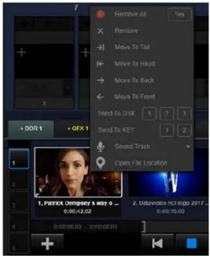
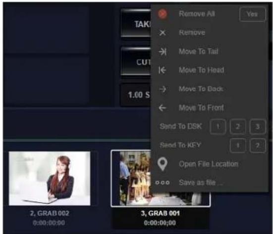
Users can right-click a specific added material to open the drop-up menu for many operations including "Remove All", "Remove", "Move to Tail", "Move to Head", "Move to Back" "Move to Front", "Send to DSK" and "Send to KEY".
For the section which is below the preview window of the list, the green bar which is located on the left side is the playback progress bar. For the right side, it is the mark-in and mark-out progress bar. Users can pull the green part of the progress bar or click a specific point for moving the video to your desired point for playing. Users can pull the parentheses on both sides of the mark-in/mark-out progress bar to set the start point and end point for the video playback. After the start point and the end point of the video playback are set, only the section between the start point and the end point will be played when the video playback is activated.

The buttons which are located on the bottom side are "Plus" button + playback control button ▶ sliders for playback regulations. Us ON Loop ON Single AutoPlay Off
"plus" button to add the capture card signal or the NDI signal. Moreover, users can press the "Play" button which is located at the center to control the start/stop of the video playback. The Previous/Next buttons are loaded to play previous or next video.
The "Loop" slider allows users to return back to the start point of the video for playing. The "Loop" slider allows users to control whether they want to loop video or not. The "Single" slider allows users to control whether they want to loop videos in the whole list or just to loop the current video.
When the “AutoPlay” function is turned on, the video playback will be resumed from the paused situation when the video is switched to the PROGRAM window. Moreover, the video playback will be paused automatically when the video is switched out from the PROGRAM window. This function is useful when the news broadcasting is finished and the news film must be appeared and played automatically.

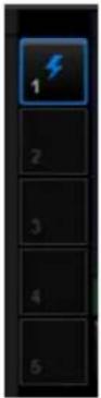
There are five numbers for the lists on the right side of the category window. Users can prepare five different lists for rapidly switching between different lists within the same category. Users can press the tag to switch to different list directly.
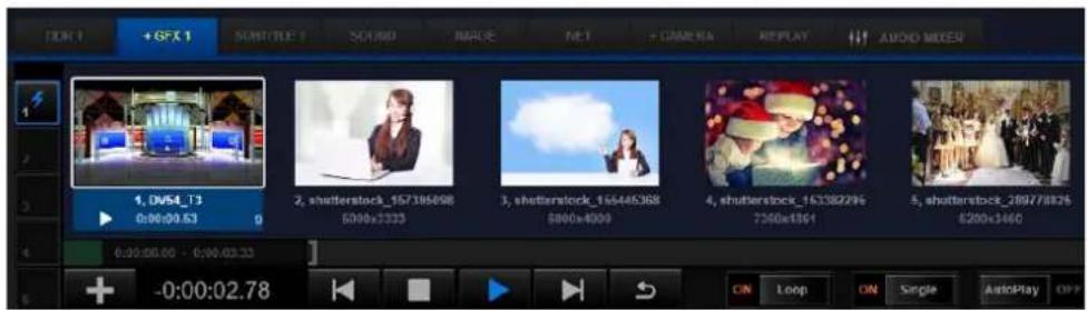
GFX 1/2: The virtual scene of the virtual studio and the graphic and text combination effect can be placed in this category.
The operation for adding the graphic and text combination into the GFX category is the same as the DDR category. Users can click the "Plus" button directly to add the needed materials into the GFX1/2 categories. After that, users can double-click the material for using it. Users can also right-click a specific item for material management. The details of the operation for the graphic and text combination and the virtual studio will be introduced in chapter 4.4 Graphic and Text Editor and chapter 4.6 Virtual Stuido.
SUBTITLE 1/2: The subtitle files that must be used frequently can be placed in this category. The operation for adding subtitles is the same as the GFX and video categories. The subtitle can be assigned to the switching channel which is assigned as the "SUBTITLE" category. For most of the time, the materials for the "SUBTITLE" category will be used as DSK or KEY overlay layers. For the details of the "SUBTITLE 1/2" operation, please see chapter 4.5, DSK and Key overlay layers.
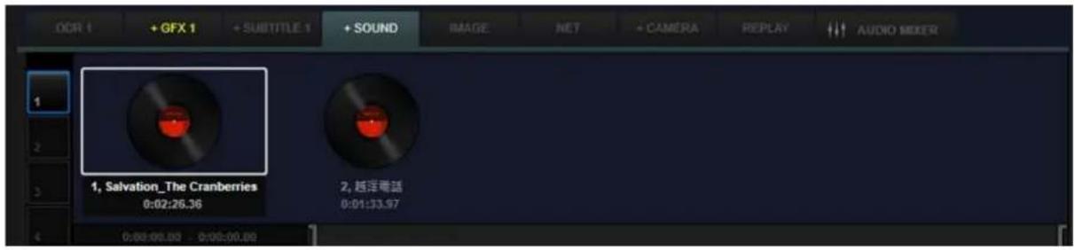
SOUND and IMAGE: The audio and image files which will be used frequently can be placed in these two categories.
The operation for adding and managing materials in this two categories is the same as the DDR category. The sound of the audio file can be heard and adjusted only when those audio files are quoted to switching channels.
GRAB: The GRAB button is located on the top-right side of the whole interface. When the"GRAB" button is pressed, the PROGRAM picture will be captured and added into this category automatically.
The operation for this option is the same as the DDR. The screenshots will be saved in the route which is shown as follows.
This PC-→Pictures→TVS
Users can right-click a specific screenshot item and then press the "Open File Location" option from the drop-up menu to open the default folder for saving the screenshot.
BUFFER: This is a material list for saving all kinds of materials. Users can save videos, images, 3D virtual scenes and graphic and text combination materials into this category. Moreover, users can assign many switching channels to show the materials of the “BUFFER” category.
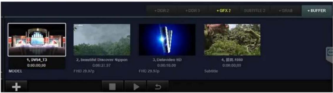
Because the number of the list for the DDR, GFX and IMAGE categories is limited, users can use the “BUFFER” category to save more video and image materials simultaneously in the switching channels for channel switching at any time.

For the “BUFFER” category, the operation procedure for applying a specific material to the switching channel is the same as the “CAMERA” category. At first, users need to click a specific switching channel which is assigned to be “BUFFER”. After that, please double-click your desired material which is saved in the “BUFFER” category and then this material will be activated to be used or played in the corresponding switching channel.
NET: The RTMP, RTSP and m3u8 signals that are input by the pull-stream can be added into this category.
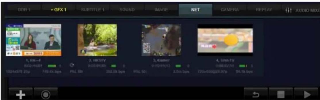
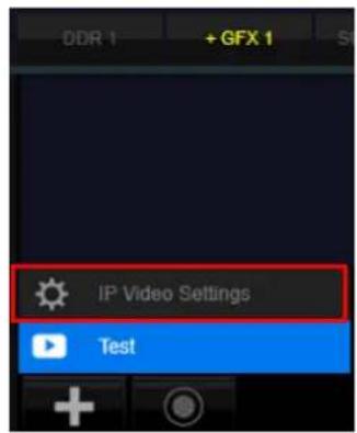
Before adding the pull-stream signals into the NET category, users need to add the URL of the signal source that is needed to be pull-streamed into the "IP Video" section in the "General Configure" option. If users want to open the IP Video settings page, users can press the "plus" button which is located on the bottom left side of the "NET" category. After that, users can press the "IP Video Settings" button from the drop-up menu. Moreover, users can also press the "IP Video Settings" option from the "Options" drop-down menu from the main interface.
![Options Help General Configure Moor Language Activity Data Safe Frames Show Blackmagic Desktop Video Utility Multirevel Layout Streaming Settings PTZ Control Settings IP Video Settings Subtitle Editor 3D 720 1600 4K Macros [ ]](/content/2026/05/830674/images/53d4ab538f4669fd2338d077e28b99122c5d8702d6d76e91f2c8de12dbace7d3.jpg)
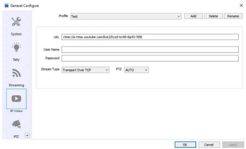
After opening the “IP Video Settings” window, users can add an RTMP/RTSP pull-stream URL and then enter the corresponding User Name/Password. Moreover, users can select the corresponding PTZ control protocol for the streaming URL which is transferred together with the PTZ control protocol. Moreover, it supports Web RTC.
After the needed pull-stream URL is added into the IP Video Settings, users can see the added pull stream URL from the pop-up drop-up menu after clicking the plus button on the bottom left side of the list for the “NET” category. Users can add this source signal into the list of the “NET” category for future application after clicking the corresponding pull-stream URL. The pull-stream source which is not added into the list will be shown in gray. The pull-stream source which is added into the list will be shown in dark black.
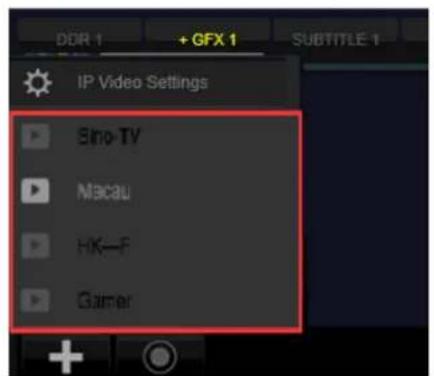
The “NET” category’s operation procedure for applying a specific material to the switching channel is the same as the “CAMERA” category. After adding the pull-stream signal into this list, users need to click the switching channel which is assigned to “NET” and then double-click a specific material in the “NET” category to active the material for using in the switching channel.
4.2.2 Switching Channels
After assigning the materials to the list of each category, users can assign 8 channels to be the switching channels for a specific category/signal for switching to the PROGRAM channel at any time or for quoting to other switching channels for signal combination.
After creating a new engineering file, the TVS-3000 system will assign default corresponding lists and categories for the 8 switching channels. If users need to change the corresponding lists and categories, users can click the tag from the top of the switching channels to select corresponding material list from the drop-down menu.
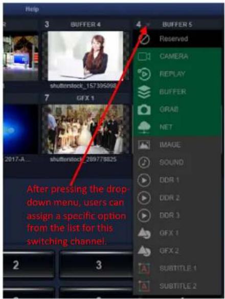
For the lists in the CAMERA/REPLAY/BUFFER/GRAB/NET categories, after a specific switching channel is assigned to a corresponding category, users need to double-click a specific material in that category to confirm that the material in the specific category is used by the switching channel.
For the lists in the IMAGE/SOUND/DDR/GFX/SUBTITLE categories, after the switching channel is assigned to a corresponding category, this switching channel will be paired to the list of this specific category. Once one of the material in the list is clicked for playing or all of the materials in the whole list are clicked for playing in sequence, they will be shown in the paired switching channels.
If users want to assign the camera signal to a specific switching channel, users need to confirm that this switching channel is assigned as “CAMERA”. After that, users need to click the preview window of this switching channel (The selected preview window will be surrounded by a white rectangular). After that, please double-click your desired camera signal in the “CAMERA” category for assigning this signal to the switching channel which is surrounded by the white rectangular. After the signal is successfully assigned, the numbering of this camera signal in the “CAMERA” category will be shown after the text “CAMERA” on the tag of the switching channel for users to confirm which the camera signal is.
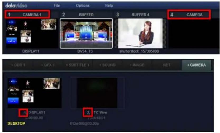
When preparing your program, users can do similar operations for other switching channels to make sure that all of the materials in all categories are loading to switching channels for your rapid switching at any time.
Note 1. If users need to use many “CAMERA”/“Pull-Stream” signals which the number is more than 8 channels, users can keep the white rectangular at a specific channel which is assigned to “CAMERA” or “NET” and then double-click the signals in the CAMERA/NET categories to apply those signals to this flexible channel to achieve “CUT” operation.
Note 2. After the preview window of the switching channel is clicked, the white rectangular will be moved to this switching channel and the drop-down menu and the switching channel layer will be corresponded to this switching channel. The above-mentioned operation rule can also be used in the following sections of this user manual.
Note 3. The content which is added in the switching channel can be switched to the PROGRAM rapidly. So, in most of the cases, the content in the “SUBTITLE” category will not be assigned to the switching channel.
4.3 Special Effect Transition and Normal Transition
Users can apply a variety of special effects for switching between PROGRAM and PREVIEW windows. The special effect transition control area which is located on the middle of the right side of the main interface. There are many buttons for selecting and applying the special effect transition.
4.3.1 Special Effects Transition
There are four preview windows for special effects transition on the top right section of the switching operation area. Users can load the special effect file for transition in these four preview window. When the cursor of the mose is moved to the top left corner of the special effect preview window, the icon of the file folder will be shown for users to select their desired files.
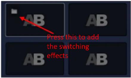
Users can press the file folder icon to add the special effects for transition into corresponding window for special effect transition. The preview of the special effect will be shown. After the window for the special effect for transition is clicked, it will be surrounded by a white rectangular. Users can click the "Take" button which is located below the preview window for switching between the PROGRAM channel and PREVIEW channel with special effects.
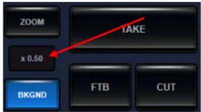
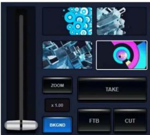
The default operation speed of the special effect for transition is determined by the total Frame Rate setting for making this special effect and the current setting for the standard frame rate. If the transiton speed is needed to be adjusted, users can use the button which is located on the bottom left side of the preview window and is on the middle of the ZOOM and BKGND buttons for adjusting. The larger the figures, the faster the transition speed is. Users
can press the left arrow and the right arrow on the button for 0.5 times step adjustment. Users can also press the figure on the middle of the button and then pull up and pull down for adjusting the figure slightly.
The following material types can be used for special effect transition.
3D Animation: The 3D animation that is created by the 3ds max software can be used to be the special effect for transition. There are some templates that are provided by the TVS-3000 system for users to create their own special effect for transition in the 3ds max. Moreover, there are more upgrading packages for template that will be provided in the future.
Image Sequence: Users can use the Image Sequence with Alpha or the video to be the special effect for transition. The files with the .amf file extension in our material package can be loaded directly to be the special effect for transition. Users can use the built-in animation generator “Animation Maker” to repackage some large files with the .mov file extension which are output from the AE/AR softwares to be the .amf files for saving the system resources. The details for making the .amf file will be described in the chapter 4.12 “AFM Animation Coverting Tool”.
4.3.2 Normal Transition
Please see following diagram for some buttons and T-bar which are located at the transition control area.
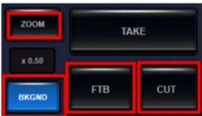
ZOOM and BKGND Buttons: This two buttons determine different functions of the T-bar which is located at the control area. Those two buttons are the only way for activating the T-bar for different functions. If the “BKGND” button is pressed, users can pull the T-bar which is located at the control area for controlling the switching between the PROGRAM and PREVIEW. When the “ZOOM” button is pressed, users can use the T-bar to control the pan and tilt of the current virtual camera lens and the target virtual camera lens.
TAKE: Press the "TAKE" button and then transition can be done between the "PREVIEW" and "PROGRAM" channels. The transition function of this button is the same as the T-bar.
CUT: Users can click the "CUT" button for switching the content of the PREVIEW channel to the PROGRAM channel for PROGRAM output immediately.
FTB: Users can click this button for replacing the PROGRAM channel by the black field gradually. This FTB button can be used in PROGRAM Fade-Out application.
4.4 Graphic & Text Editor for making Graphic & Text Combination
The TVS-3000 provides a built-in full-function graphic and text editor for users for creating subtitle template and graphic & text combination such as the multi-window animation for a variety of purposes. Each graphic & text combination can include up to 12 layers of the graphic and text combinations for users to combine with different materials for creating complicated subtitle and graphic & Text combination effects.
Users can open the graphic & Text editor by clicking the "Subtitle" Editor" from the "Options" drop-down menu.
![Options General Configure User Language Activity Data Safe Frames Blackmagic Desktop Video Utility Multiviews Layout Streaming Settings PTZ Control Settings IP Video Settings Subtitle Editor 50 720 1080 4K Macros [R]](/content/2026/05/830674/images/039f556730ac145ac612933bf0c5f188e7bd2a4d5f19b0f46b92a2e6070401a4.jpg)
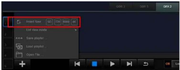
Users can also click the "Plus" button from the bottom-right side of the lists for the "GFX" and "SUBTITLE" categories. After that, users can click the "Insert New" option from the drop-up menu to select your desired resolution for the graphic & text combination layer.
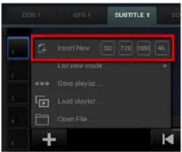
4.4.1 Main Interface of the Graphic & Text Combination Editor
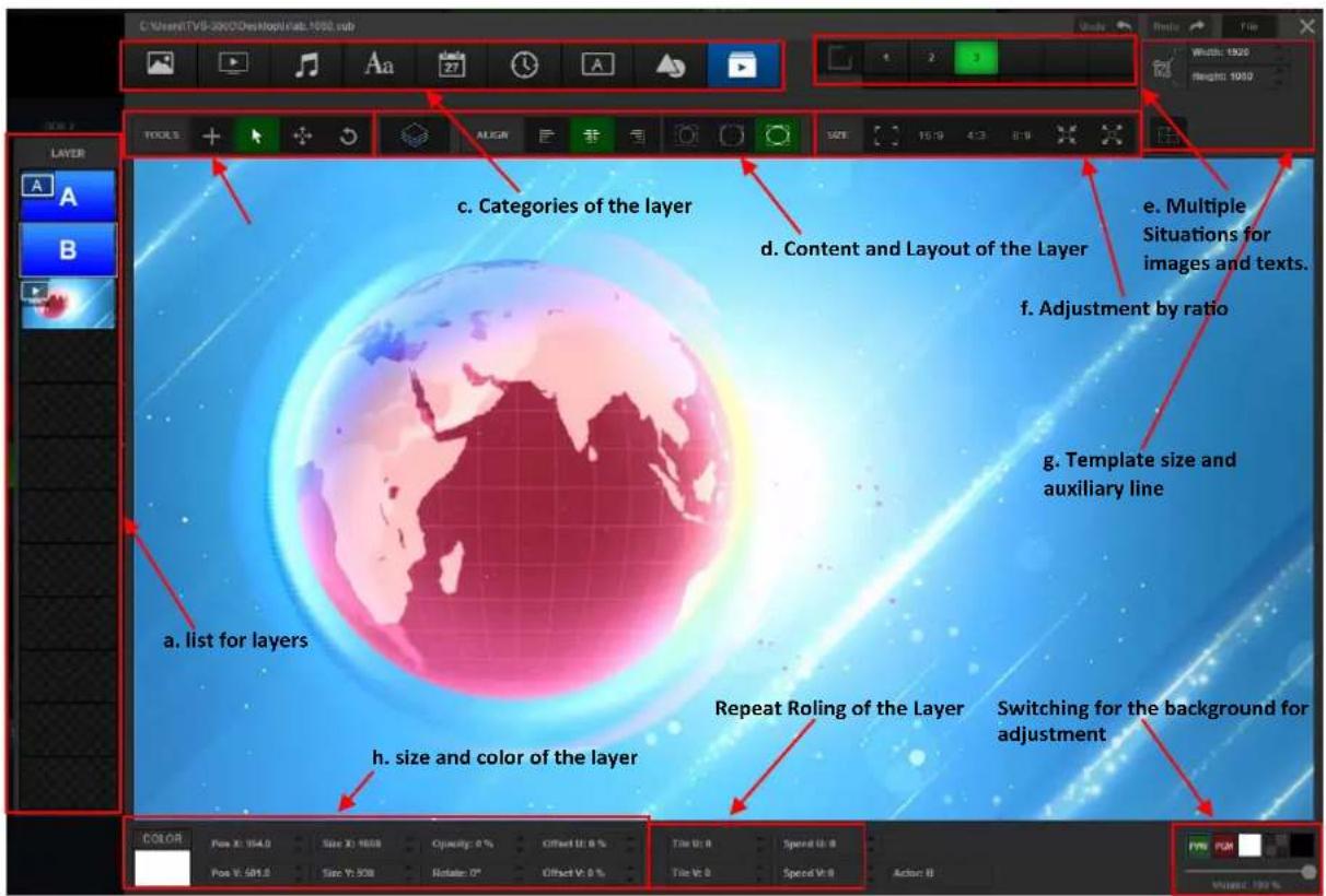
a. List for Layers: Users can add up to 12 layers into the list, the thumbnail of those layers will be shown in the list for layers. The layers which are located on the upper side of the list will overlay the layers which are located on the lower side of the list when they are shown as graphic.
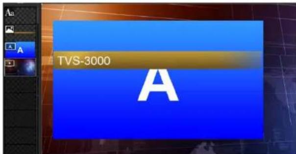
Users can assign current layer for control by clicking the thumbnail of a specific layer. Moreover, users can control the overlay sequence, showing and hiding of the layers by the pop-up menu after right-clicking a specific layer. Users can also press and hold the shift button to click multiple layers to select many layers at the same time for adjusting the location and angle simultaneously.
b. Mouse Cursor Mode: Users can active different buttons in this area by clicking. Moreover, users can change the operation mode for the layers by the mouse cursor. There are four modes which are shown as following for users to select.

Create.

Move.

e.

c. Categories for Layers: When the mouse cursor mode is active to be "Create", users can click the buttons in this area for selecting their desired layer category for creating. After the desired layer category is selected, users can drag a rectangular for creating a graphic and text combination for the corresponding layer. The icons for different corresponding layers are shown as following diagrams.
Image
Clock
Video
Channel
Audio
Shape
Text
Layers for Different Categories
Date
d. Content of the Layer:
After the Image/Video/Audio layers are created, users can click the content add
button on the layer content area to select the file with corresponding file format to be the content of the layer.

After the Text layer is created, users can click the "Select" button and then the editing window for Text will be pop-up for users to set the text font, to enter text directly or to import the txt/rtf text file. If the graphic and text combination template with text will not be redefined after the template is imported, the content of the entered text will be displayed as the default text.
After the Date/Clock layers are created, the real-time date and time will be shown in that specific graphic and text combination layer. If that graphic and text combination layer is
selected, users can adjust the format for displaying the date/time at the bottom right corner. The Channel/Different Categories layers are special. Users can quote contents of other switching channels or signal sources to this kind of layer to achieve the graphic and text combination which is made by multiple signal sources.
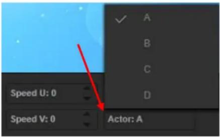
After the Channel layer is created, it will use the channel layer of A as its default layer for selecting the content of the switching channel in the switching channel menu. If users need other channel layers including B/C/D, users can click the "Actor:A" to show the drop-up menu from the bottom right corner to select their desired channel layer.
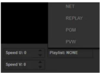
After the Category layer is created, the characters “Playlist” will be displayed as default on the layer. At this time, users can click the “Playlist:NONE” which is located on the bottom right corner to select the desired source/material categories for this layer from the drop-up menu. If there is a content for the corresponding category which is played, this corresponding content will be shown in this layer.
There are two set of buttons for Character Define and Image Alignment which are located on the right side of the Image Content and Layout areas.
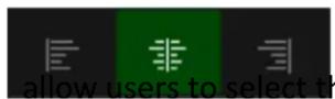
The Character Alignment buttons allow users to select the settings for
Left Alignment/Center Alignment/Right Alignment for the characters in the character layer.
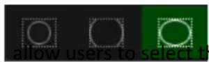
The Image Alignment buttons allow users to select the layer with
image-only content for setting the corresponding alignment/cropping ways. The buttons which is shown in the sequence of left to right is Maintain proportionality to height, Maintain proportion to fit width, The scaled layer area is completely filled.
e. Multi-Situation Graphic and Text Combination
Users can save up to 6 situations into one graphic and text combination. This allows users to record different situations including location of the layer in the combination, size, transparency and hiding. Moreover, it allows for animation transition in different situations.

After pressing the short horizontal line which is below the corresponding number allows users to duplicate one set of situation for each layer from other numbers for further editing.
f. Adjusting the layer according to the aspect ratio
When adjusting a specific layer, users can use buttons which are located at the Proportional adjustment zone to adjust the aspect ratio of the layer rapidly.
Those three buttons are shown in left to right sequence for "Keep the
Width ratio of the layer", "Change to height of the layer", "Change the layer to the corresponding raito directly".
This button allows users to keep the width ratio and to change the height for
changing the layer to the self-defined ratio which is the same as the content which is loaded to the layer.
This button allows users to change the width and height of the layer to be the same as the original size of the content which is added to the layer.
This button allows users to change the width and height of the layer to be the full size which is the same as the whole range of the graphic and text combination template.
g. Template Size Adjustment and Auxiliary Line
Users can change the size of the graphic and text combination template at any time during the editing process except the selected standard size when creating the graphic and text combination. This can fit the special demand for placing the template to the non-standard surface or non-standard overlay location.
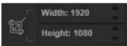
Users can click the figure and then pull it up and pull it down to change the figure. Moreover, users can click the up triangle/down triangle buttons for adjusting the template size of the graphic and text combination directly.

In order for convenient setting and adjustment, users can click the auxiliary line button which is located below the template size to turn on/turn off the auxiliary line.
h. Adjustment for Layer Size and Colors
For the contents in the Text/Date/Clock Layers, users can click the color button from this area directly for adjusting the colors for the content of the layer.
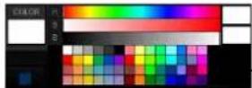
The two color blocks which are located at the right side of the palette represent current selected color and the selected color for previous time.
For all contents in the category layer, users can adjust the coordinate, size and direction of the layer by adjusting the figures which are located on the right side of the palette area.
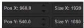
The figures in the Size/Location adjustment area list the locations of the X/Y coordinates and pixel size of the horizontal/vertical directions. The corresponding figures can be adjusted by clicking the up and down arrows on the right side of the figures. Moreover, users can click the figures and then pull-up/pull-down the mouse cursor for adjustment.
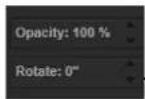
The parameters which are located on the right side of the location area include transparency of the layer and the figures for rotation angles. The clicking for adding/reducing and pulling up and down adjustment are also supported.
i. Offset/Scrolling of the Layer Contents
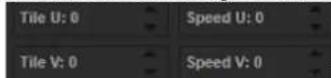
This area allows users to adjust the location offset in the layer for the material or signal which is loaded to the layer for showing the needed sections within the layer range. Users can adjust the offset of the horizontal and vertical contents by pulling/adding or reducing the values of Tile U and Tile V. Moreover, users can also achieve the scrolling effect of loading material or signal along the horizontal and vertical directions by pulling/adding or reducing the values of Speed U and Speed V.
j. Switching and Adjusting of the Background
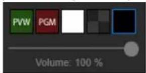
This allows users for previewing the effects which the graphic and text effects are applying for the pictures.
4.4.2 Editing for Multiple Layers Graphic and Text Combinations
Take the way for making a multi-window and multiple dynamic graphic and text combinations for example, users can show a typical operation for adding various factors including GFX, DDR, Text and the contents from other switching channels in the CG editor. The CG packages which are edited and saved in the GFX and SUBTITLE categories will be added into the content list. Users can open the CG editor by clicking the “plus” button and then pressing the “Insert New” option.
Add video to be the background of the CG: Users can click the "+" icon from the tool bar and then to select the Video icon to be the element of the layer for creating a new layer by dragging a rectangular.
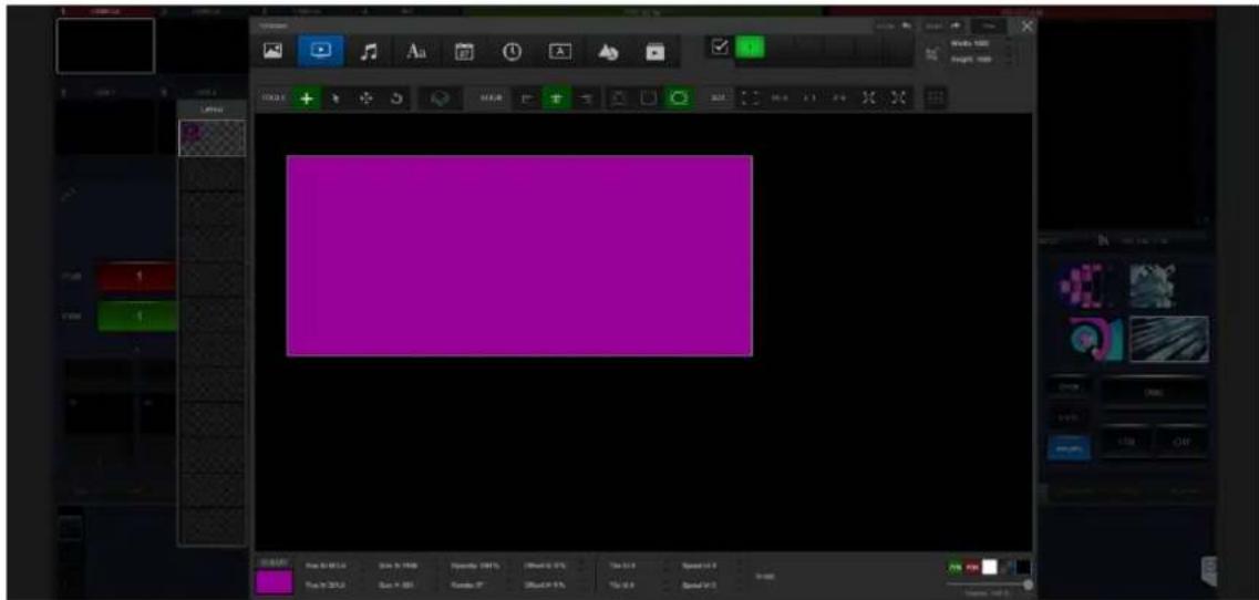
If users want to select Video to be the background of this CG, please choose the layer for loading a video file at first. After that, please click the "Full Screen" button for adjusting the layer to be full-screen size.
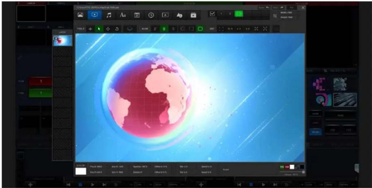
If users want to set a window which provides the main system signal in the virtual studio and to set another window for showing the news broadcasting, users can click “A” at first and then try to drag another window for quoting the signal of other channel. After that, please do the same operations for creating a “B” window.
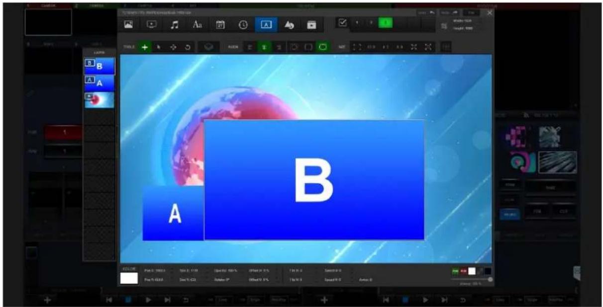
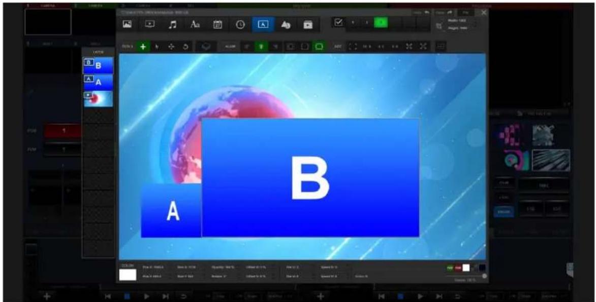
Uses can use the same operation for creating a shape and then change its name to be "B". After that, we can use the "RESET" button to set its width and height ratio to be standard size and then use the mouse cursor or the arrow on the keyboard to move the shape to another side.
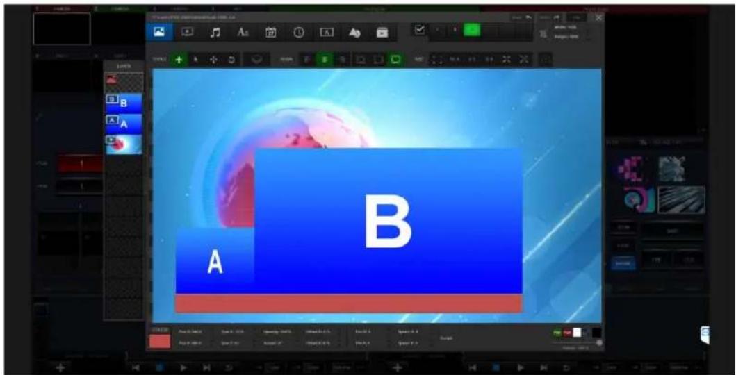
There is a subtitle template which is added for a banner for introducing the content which is playing. Please click the "Image" button and then please load the tag file for the template. After that, please drag it to adjust the size for suiting the buttons for A window and B window.
After that, users can add text into the subtitle board. Please click the "Text" button for adding text. After that, please drag another layer on the subtitle board. After the creating of the text layer is finished, please click the "Select" button and then please double-click on the text layer for entering your desired texts.
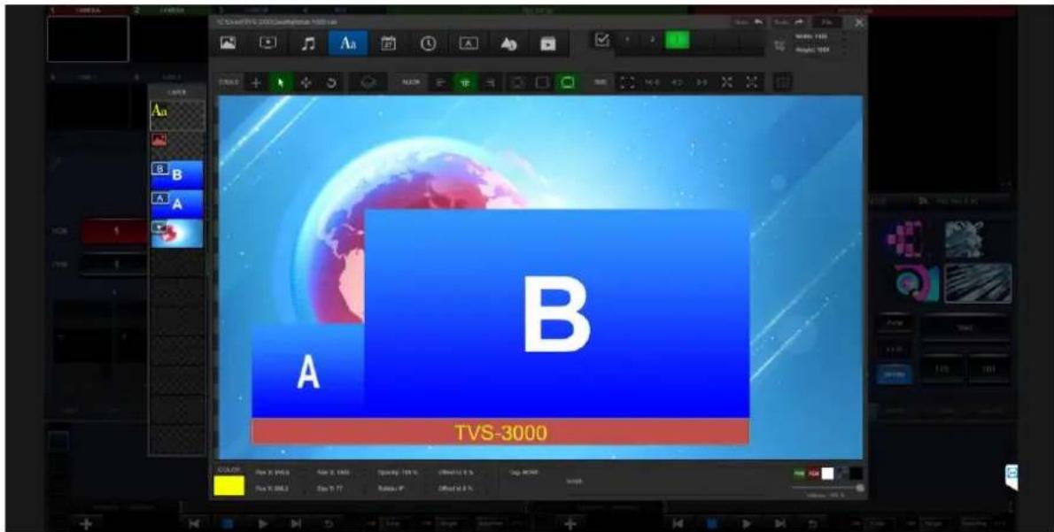
Please click the "File" button which is located on the top-right side for saving the CG and then please select the file name and folder for saving it. The saved CG file will be kept in SUBTITLE format file and then will be added into the list of the GFX2.
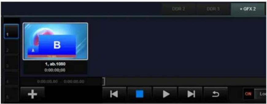
4.4.3 Apply the CG Package Content from Channel to the BCD Windows
The CG package that is added to the A, B, C and D windows can be used for the loading contents for other switching channels for creating fascinating CG effect. We will use the CG package which is created in advance and the B window to show how to apply those contents. Please assign one switching channel to GFX2 and then double-click the CG package for loading.
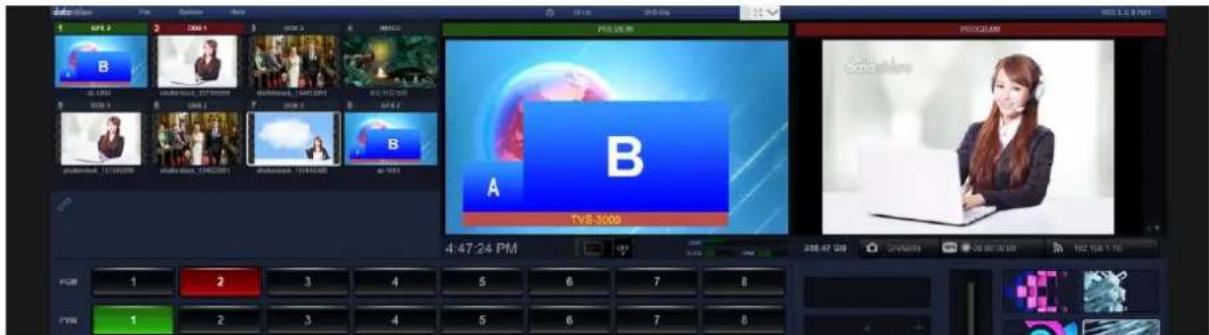
Please select the 8^th switching channel(If the channel is surrounded by the white rectangular, it means that this channel is selected). After that, please click the “Link” icon which is located on the left side of the switching channel and then please select “Channel” from the dropdown menu. The channel setting row is located below the switching channels. All of the channels will be shown in the channel setting row.
![5 DDR 1 6 DDR 2 7 DDR 3 8 GFX 2 shutterstock_157395098 shutterstock_134923091 shutterstock_155445368 ab.1080 Channel [N] Matting [M] Adjust [J] Captions [T] Object [O] Macros [G] P 2 3 4 P 2 3 4](/content/2026/05/830674/images/cdac14be924c7bbbb77fc812811e81f21f681b4c10917b56eb1a1aaa413d5257.jpg)
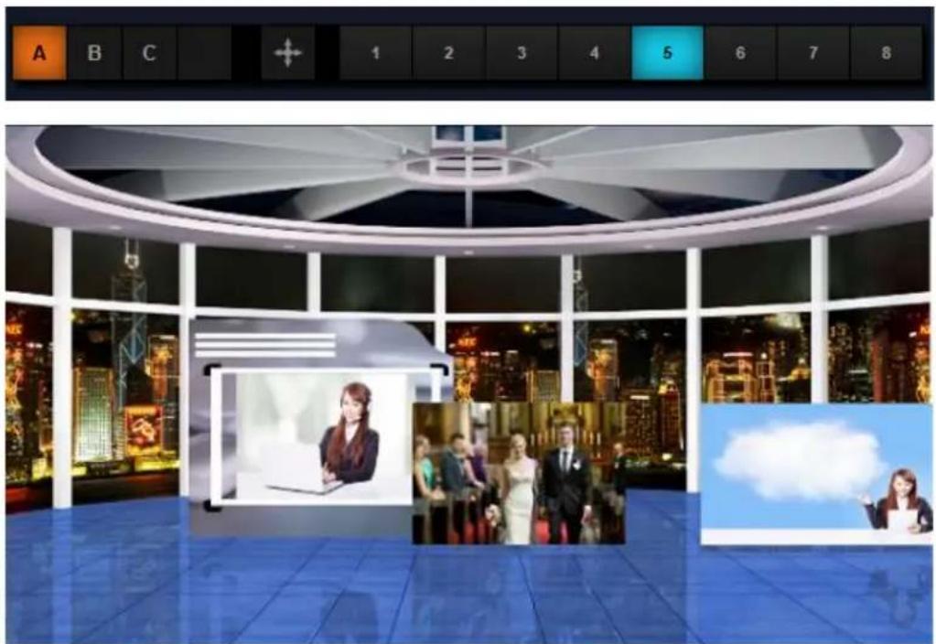
Users can load signals for A and B windows. Because the A and B windows are created by users, there are A and B buttons in the row for users to select. Moreover, there is a channel selecting line which is located after each corresponding icon (A/B). Users can select any switching channel from channel 1 to channel 8 to add signal to a corresponding channel. In this example, we will transmit the signal in the 5^th channel to the Window A and then transmit the signal in the 3th channel to the Window B.
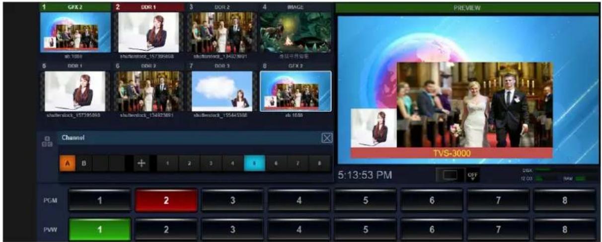
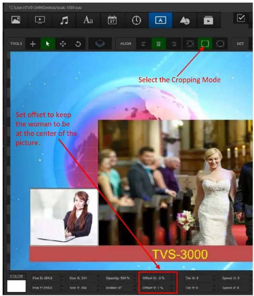
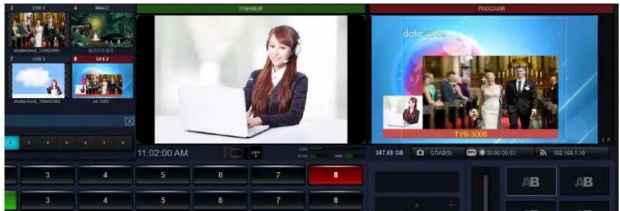
Users can see that the signals for the 5^th channel and the 3th channel are shown in the A window and B window respectively. However, we can see that the signal for the 5^th channel is shown to be out of shape. Because the original picture is shown in the ratio of 16:9. So, users can right click the list in the GFX2 to modify this issue.
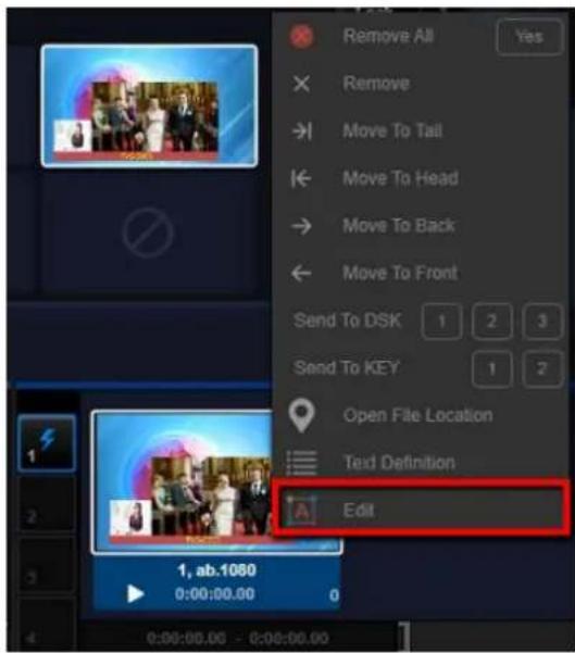
Please select the "A Channel" button for using the adjustment tool for adjusting the signal of the 5^th channel.
After that, a CG package is completed and it can be used as a new virtual camera scene. Moreover, users can create up to 12 layers of the graphic and text combinations for giving many messages within a CG package for your audience.
4.4.4 Create a PIP with more than 4 Live-Scenes by the the Category Layer
The category layer allows users to select a category or source from the CMAERA/NET categories to be its content. So, users can add up to 4 real-time picture channel layers. Please select the last icon from the layer category tool bar and then drag it to become a rectangular. Finally, the category layer will be shown as following diagram.
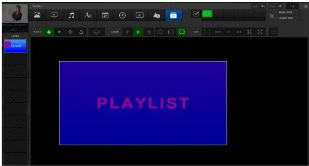
Please select this category layer and then users can find the playlist options in the adjustment area.

After that, users can select a category or select CAMERA/NET. After that, users can select the ID code from the bottom side to select the CAMERA/NET playing source which the ID code is in this layer.
Users can also duplicate or create more category layers for assigning other real-time contents for those layers.
4.4.5 How to Create and Use a Captions' Subtitle Template
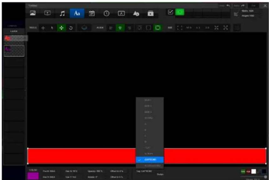
Please select or create a Text layer in the Graphic and Text Editor. After that, please select "CAPTIONS" from the "Tag" drop-down menu and then please save this engineering file.
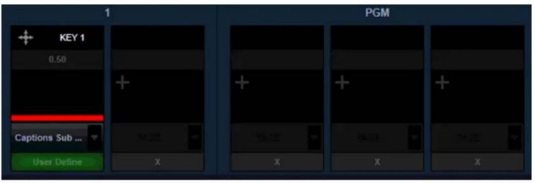
Please load the currently saved Captions subtitle template into the DSK layer of current channel or the KEY layer. After that, please show it to PREVIEW or PROGRAM.
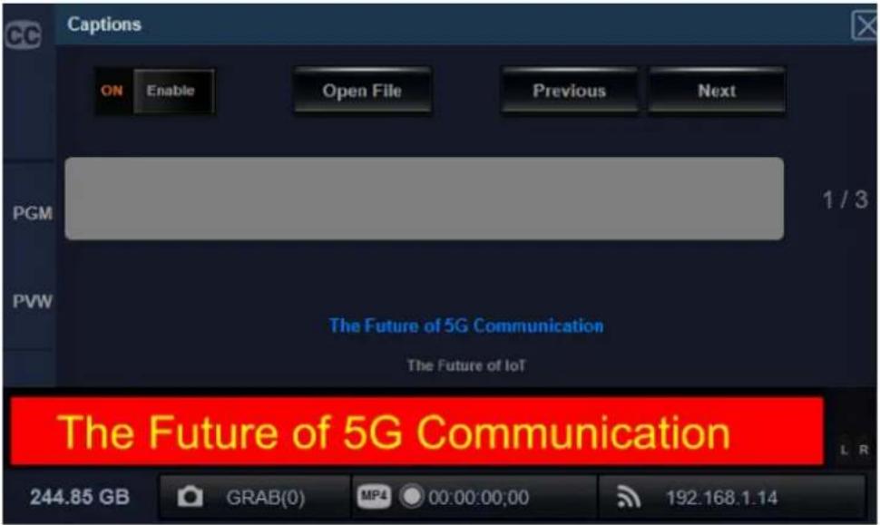
Please click the icon which is located on the left side of the switching channel to open the channel function drop-down menu. After that, please click the "Captions" option to load the pre-saved text file.
![Captions Channel [N] Matting [M] Adjust [J] Captions [T] 2:3 Scoreboard [S] Beauty [E] Object [O] Macros [G] Open File Previous Next 1 / 0](/content/2026/05/830674/images/55623e1e5a90630786d36ab55956baae2aea0773e718e6eeee2e46aec07a0332.jpg)
After the Captions "Enable" slider is switched to "ON", users can switch the content of the Captions which are shown on the screen by pressing the "Previous" or "Next" button.
Important Notice for creating, saving and the file format of the .txt file.
Before saving the .txt file, please remember to break the texts in advance.

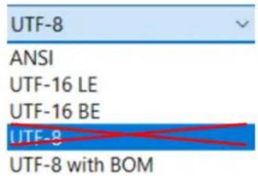
The UTF-8 text format is not supported by the TVS-3000, so, please remember not to save the .txt file in UTF-8 file format or it will be shown in garbled .txt file.
4.5 DSK Layer and KEY Layer
There are two kinds of overlay layer locations for placing coner mark, subtitle and text for applying them rapidly for the TVS-3000. The names for those layers are "DSK Layer" and "KEY Layer" respectively. Those layers are located at different areas in the main interface.
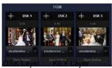
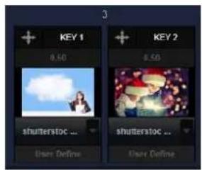
The content in the "DSK Layer" window will be used for PGM output signal. The "KEY Layer" window will be used for current selected channel. This means for the selected channel which is surrounded by the white rectangular, the content in the layer window will be changed to the corresponding layer when switching channels. However, for the "DSK Layer", there is no affect.
4.5.1 Add material to the DSK Layer/KEY Layer
Please right click the material in the list of the category. When users right-click one of the content in the category, users will find the options for transmitting the content to the DSK Layer and KEY Layer.
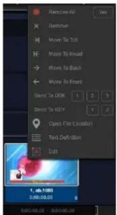
This is the simplist and direct way for transmitting some materials to the DSK Layer/KEY Layer. It is easy for adding but it is hard for switching because the operation is based on single content. So, we can use other way to achieve this operation.
How to choose the categories for Overlay Layer for DSK Layer/ KEY Layer.
If users move the mouse cursor to the top-left corner of the DSK Layer/KEY Layer, there is a "plus" icon for users to click to selected the category of this window from the drop-down menu.
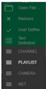
For the DSK Layer, the way for operation is easier. If users need to use KEY Layer, users need to select the corresponding channel. The corresponding channel number will also be shown on the top of the layer window. After that, users can add corresponding content into the layer window.
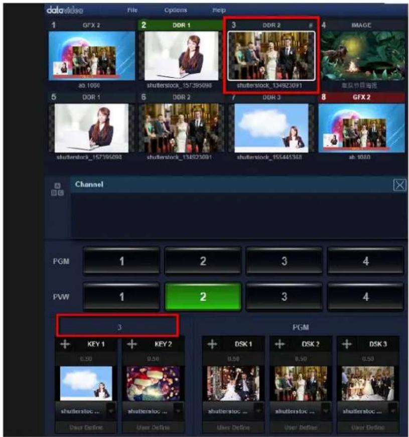
4.5.2 Showing/Hiding of the Contents for the DSK Layer/KEY Layer
The content for the DSK Layer and KEY Layer can be shown by fading-out simply to achieve transition effect. There is a button which is located below the content window shows the transition effect which is applied for this DSK Layer/KEY Layer. The default setting for all of the five windows is “Fade”. Moreover, there is a drop-down menu for users. If users click the down arrow, users can create their own transition effects for the DSK Layer/ KEY Layer.
4.5.3 Location and Size Adjustment for DSK Layer/KEY Layer
The TVS-3000 allows users to adjust the location and size of the DSK Layer/KEY Layer from their windows on the screen. Please click the direction arrow which is located on the top-left side of the DSK Layer/KEY Layer windows. After that, this icon will become a blue icon for reminder. The name of the window will be shown on the top of the location panel for pointing out the current adjustment window.
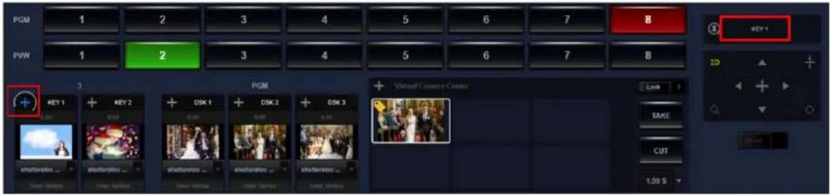
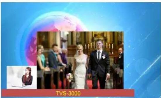
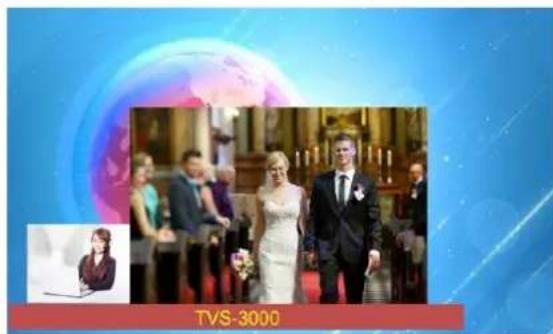
Please click "Fade" to show the "DSK Layer" on the PGM channel and then users can see the adjustment clearly. The basic way for the operation for that area is that users can click the
center for dragging it freely or to click the four direction buttons, or adjusting slightly. Please click the magnifier icon, dragging, zooming in and zooming out the content. Users can also drag the rotation icon, rotating the content. Moreover, users can click the pad icon for adjusting the aspect ratio.
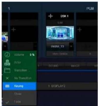
4.5.4 Use DSK Layer/KEY Layer to add the PREVIEW/PROGRAM Keyer Signals
For the TVS-3000, users can add the material into the “CAMERA” category and then use the CG with alpha channel for the Keyer signal for the PREVIEW channel. For the Keyer signal of the PROGRAM channel, users can select one DSK/KEY layer and then select the desired Keyer signal from the drop-down menu.
4.6 Chromakey, Beauty and Virtual Scenes
The Datavideo TVS-3000 provides powerful built-in Chromakey and real 3D virtual Studio 360 degree virtual tracking shooting functions. The TVS-3000 allows you to create your own story in a colorful virtual space by simply using a blue/green plastic mat.
4.6.1 Chromakey Settings
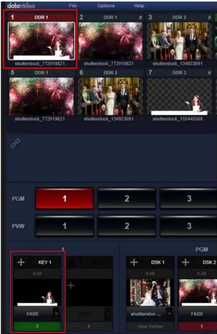
At first, users need to select the switching channel for applying the Chromakey. Please click the "Link" icon which is located below the switching channel and then please select the "Matting" option which is shown as following diagram.
![5 DDR 1 shutterstock_155445368 A Channel [N] B G Matting [M] P Adjust [J] C C Captions [T] O bject [O] P Macros [G]](/content/2026/05/830674/images/f9f540d6aad06d89b0f56946a2dcbbb848e9f11f91b39c60b9cc82ed1729cf83.jpg)
This area will list related parameters for Chromakey, please set the Chromakey function by following steps.
Select Color:
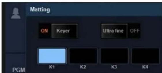
When the background color is selected by users, the Chromakey function will be turned on automatically. What users need to do is to click the K1 mark for one time and then the mouse cursor will become the eyedropper tool for users to select the color that is needed for removing(Blue or Green). Click the color again to set that color as the K1 mark.
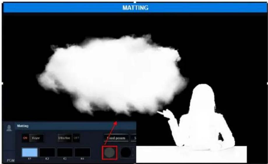
After that, the blue background will become black. If the alpha channel is shown, users can click the gray eraser for one time. If the gray eraser is clicked again, the picture will be shown in normal mode for displaying. If there is some white spots which is shown on the black background, users can repeat the above-mentioned steps by using the K2, K3 and K4 marks.
Erasing:
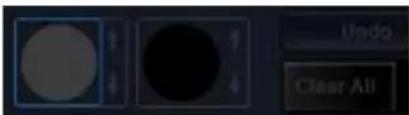
Users can use a virtual eraser for adjusting the alpha channel on some trivial sopts. Please click the white eraser and then the chromakey signal will become white and black for showing the situation of the alpha channel. Users can use the white eraser for cancelling the chromakeyer on the area which is erased previously. Moreover, users can use the black eraser for adding the forced chromakeyer on the previously erased area.
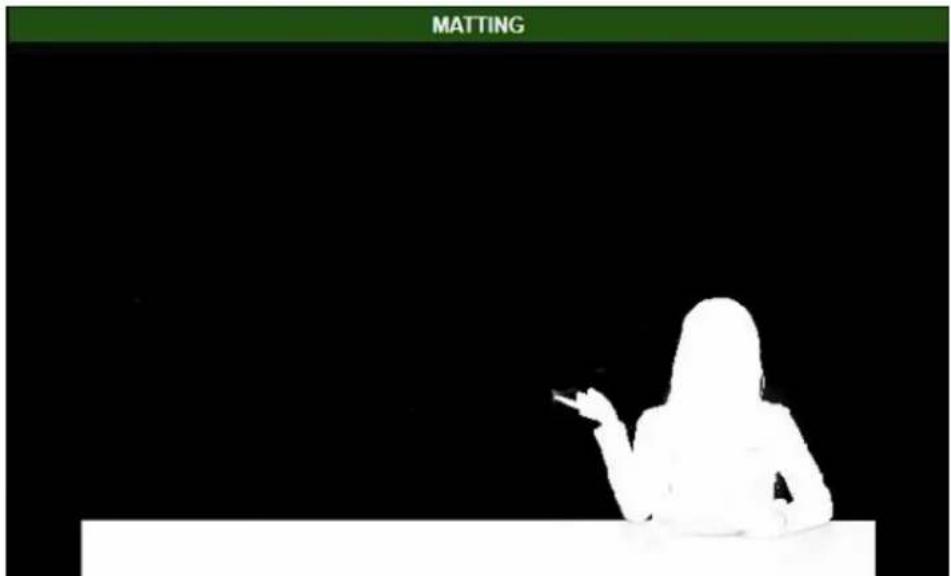
Users can select
the size of the eraser. If users delete something mistakenly, users can go back to the last step by the undo button.
Adjust the Alpha Channel Slightly
Users can add the chromakeyed picture to another channel or use the white and black picture to check the picure after it is chromakeyed for further adjustment of the Alpha channel.
The “opaqueness” can be adjusted by users. Please slide the slider to the right side for slight adjustment until the Alpha channel becomes white totally.

bar
| Category | Value | | ------------------ | ----- | | Tone Compensation | 0.000 | | Opaqueness | 0.000 | | Strengthening | 0.000 | | Soft Edge | 0.000 |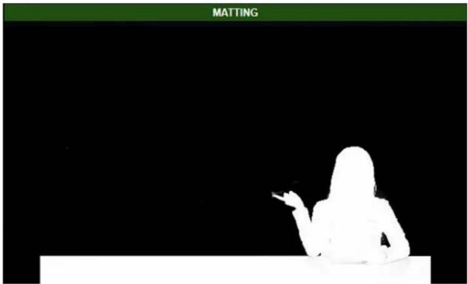
After that, please adjust the "Tone Compensation" setting, please slide the slider to the right side until the color picture that is seen by users has similar color with its original signal.
natural_image
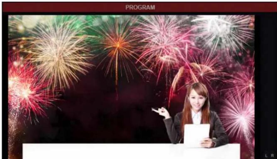
Woman presenting at a podium with fireworks in the background (no text or symbols visible)Finally, if there are some extra colors that are found on the edge of the person, users can slide the "Soft Edge" slider to the right side for adjusting the softness of the edge.
4.6.2 Beauty
Please select the switching channel which needs the Beauty function. Please click the chain
icon which is located below the switching channel. After that, please press the "Beauty" option.
![Channel [N] Matting [M] Adjust [J] Captions [T] Scoreboard [S] Beauty [E] Object [O] Macros [G]](/content/2026/05/830674/images/c17a4e9b38e32eaf02ca3840cbbaa9a00b01a9ce97df24d401dd1b9dd63b1321.jpg)
Users can whiten the skin tones or fine-tune the skin tones by using sliders or presets.
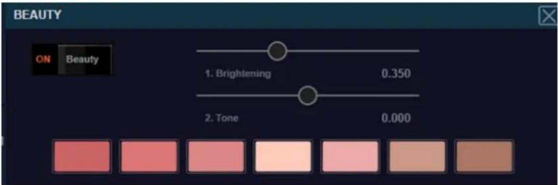
4.6.3 Load Content into the Virtual Scenes
Load Virtual Scenes: Please package the virtual scenes as a .zip file for loading to the GFX category and then users can double click the file in the GRAB category list for loading a virtual scene for the switching channel.
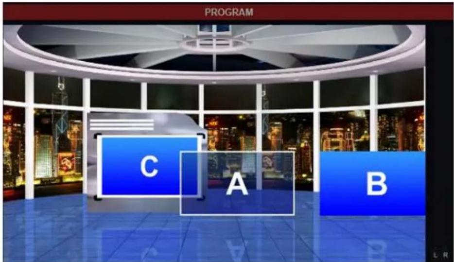
Load Content into the Virtual Scene: Users can open the Channel function bar from the "Link" icon which is located on the left side. Users can distribute the content for displaying in the A, B, and C channels by using the "Channel Setting".
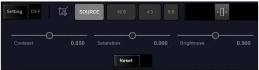
The Adjustment of the Input Signal: There is a different lighting status which is existed between the Chromakey signal and the virtual studio. So, users need to adjust the signal of the person frequently for incorporating it into the virtual scene. Please select the channel which is needed to be chromakeyed. After that, please open the “Adjust” tool from the “Link” icon.
![datavideo File Options Help 1 DDR 3 2 DDR 1 # 3 DDR 2 4 DDR 2 News 31 shutterstock_157395098 shutterstock_155445368 shutterstock_155445368 5 DDR 1 6 DDR 2 7 GFX 1 # 8 GFX 2 # shutterstock_157395098 shutterstock_155445368 shutterstock_134923091 ab.1080 Channel [N] Matting [M] Adjust [J] Captions [T] Object [O] Macros [G] 2 3 4 2 3 4](/content/2026/05/830674/images/d12149bb626fdec59f4ae590632d8f517d35e1b00472dfbd3fd505043ec5d284.jpg)
In this “Adjust” tool, users can adjust the aspect ratio, contrast, brightness and saturation of the picture for current signal source. After the adjustment is finished, it will achieve better incorporation with the virtual scene. The way for moving the object in the virtual scene will be mentioned in following paragraphs.
4.6.4 The Adjustment for Virtual Objects and Position of Virtual Camera Lens
Moving and Adjusting the Virtual Object: Please click the direction icon which is located before each virtual object for adjusting it. When the direction icon becomes blue, the name of the object will be shown on the top of the location panel.

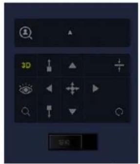
The way for operation is almost the same as the adjustment of the DSK Layer/KEY Layer. Please click and drag for adjusting the size, direction and the aspect ratio of the virtual object. What is different is that it allows users to adjust the location of the virtual object within the real 3D space. When the center is clicked and dragged, the object will be moved forward, backward, to the left side and to the right side. When the four direction arrow buttons are clicked and pressed, the virtual object will be moved to the up side/down side/left side/right side respectively.
Creating and Moving of the Virtual Camera: Users can create 6 virtual camera positions by the TVS-3000 software. Moreover, users can also achieve 360 degree virtual tracking shooting.
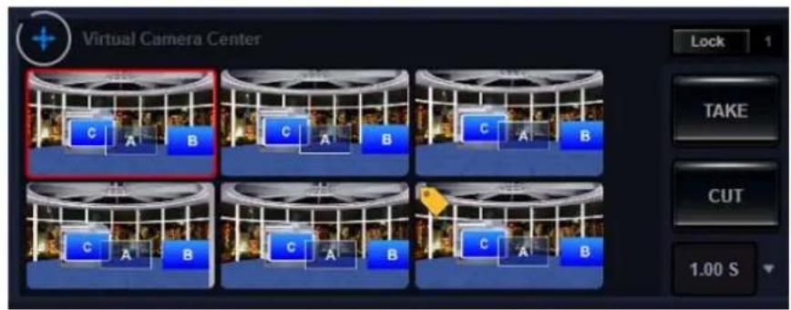
Users can click one of the six virtual camera and then the position adjustment function will be activated. After that, the virtual camera which is surrounded by the white rectangular can be controlled by users. Please try to adjust the virtual camera position by clicking and dragging and then users can see that the virtual camera is moved in the 3D virtual space. Once another camera is selected for adjustment, the current status for the virtual camera will be saved. Because the virtual camera is adjusted in 3D ways, the rotation icon can be clicked and dragged for panning and tilting of the virtual camera. Users can control the virtual camera to achieve the virtual rocker arm and close-up shooting effects
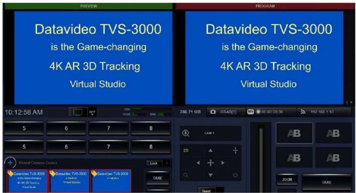
Use the Virtual Camera for 2D Focusing: For the 2D object such as .ppt file or some videos which the details must be shown for audiences, users can use the virtual camera for achieving a Close-up shooting effect.
4.7 Audio Mixer
The TVS-3000 provides a built-in audio mixer for users to manage the regulation for the audio mixer for each channel. Moreover, it allows users to adjust the output volume, monitoring volume and balanced analog audio input volume.

Please click the “Audio Mixer” tag on the top the material list for switching to audio control panel. The audio channels are designed to be one on one for the 8 swching channels. Users can monitor the audio volume for each channel and then set the regulation for it.
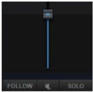
Users can adjust the volume level of a specific channel by dragging the slider. Press the "FOLLOW" button will keep transmitting the audio of the audio for a specific channel to the PROGRAM channel. If the "MUTE" button is pressed, the audio of this channel will not be output to the PROGRAM channel. If the "SOLO" button is pressed, only the audio for the specific channel will be output and the audio output for all other channels will be turned off.
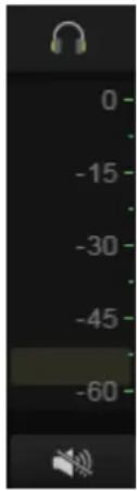
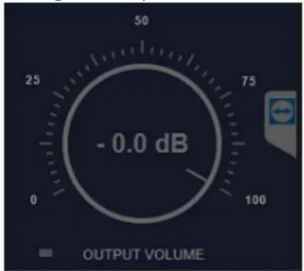
The volume control slider which is located on the left side of the control panel can control the audio volume of the audio card in the TVS-3000 system. Generally speaking, this audio source is used for monitoring for the output audio. The “output volume” is the main volume control of the audio output signal.
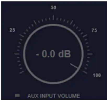
The AUX Input Volume is the balanced/unbalanced audio card input volume control for the analog audio input.
4.8 Streaming/Recording
4.8.1 Streaming
The TVS-3000 is a IP-based product with built-in streaming function and local RTMP server. It allows users to open the streaming settings from the drop-down menu from the control bar. Users can select the existed server from the drop-down menu or click the "Add" button for entering the URL of the new server.
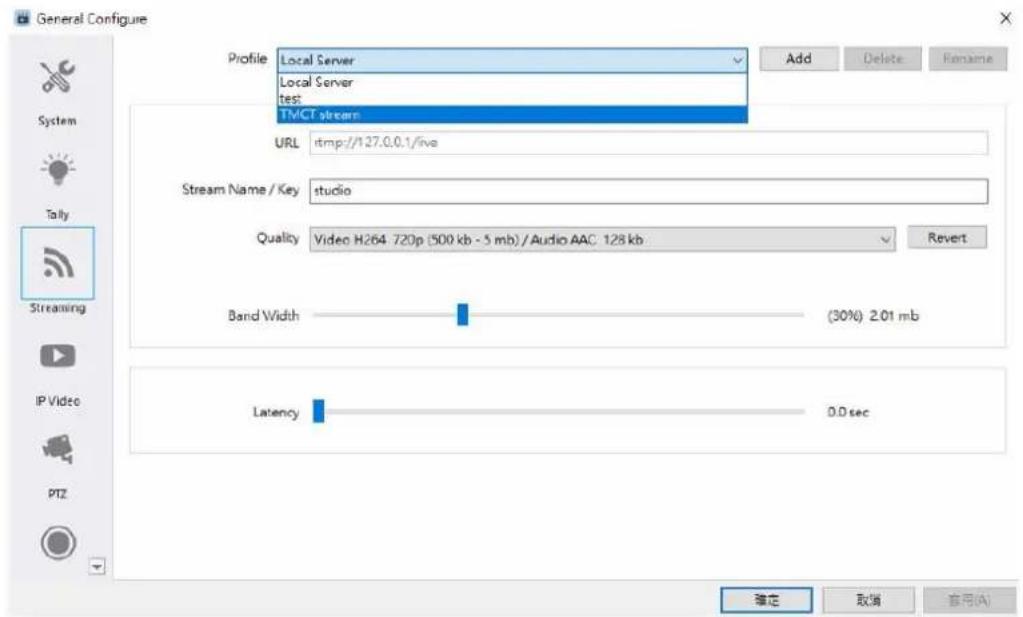
After the adding is finished, users can click the streaming icon and then the bitrates for all of the streaming servers will be listed.
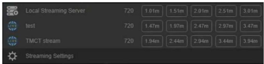
Please select the streaming server according to your uploading speed, it is recommended that the bandwidth must be at least two times of the bitrate of the streaming media.
4.8.2 Video Recording to Local Hard Disk
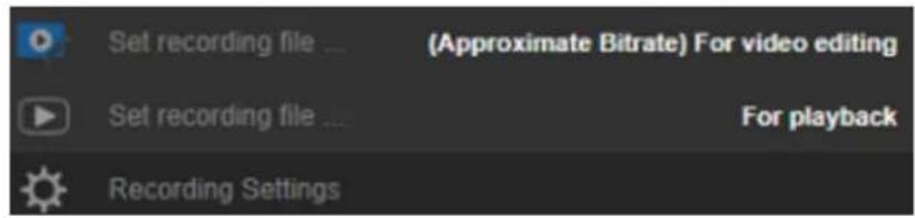
Please click the Record button for recording the pictures from the PGM channel to the local hard disk. The current supported file format includes .mov, .mp4, .ts and .MXF. When the recording is in process, the record icon will be shown in red. The recording can be stopped at any time by users.

Users can select two recording video modes including "For video editing" and "For playback".
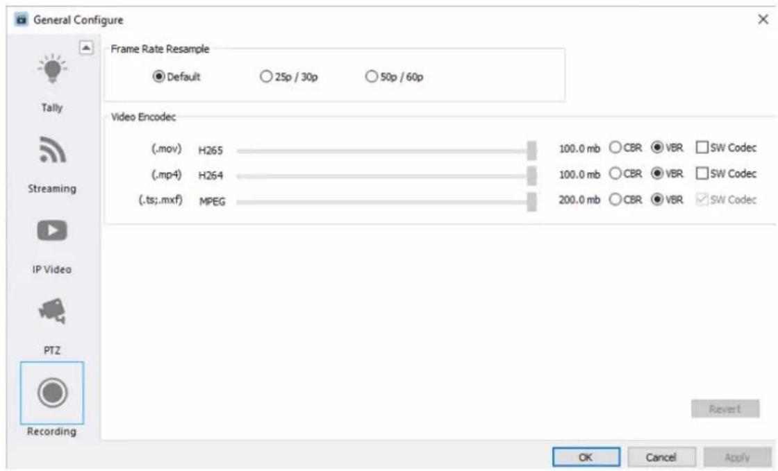
Users can modify the recorded video encoding and Frame Rate from the "General Configure" option. After the Frame Rate is modified, the Fram Rate for the output signal will also be modified.
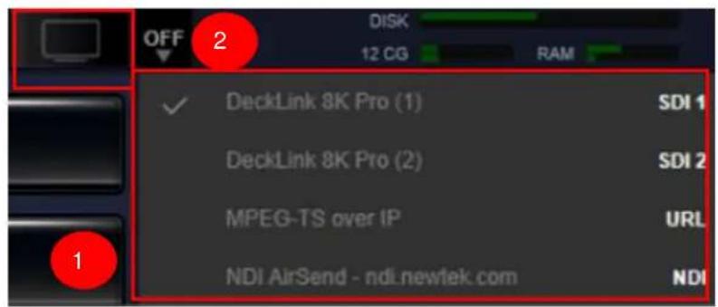
4.8.3 Video Output
Please select your desired output channel and then turn the output switch to "ON" for further video output.
4.9 Capture Card Settings and File Related Settings
4.9.1 Safe Frame
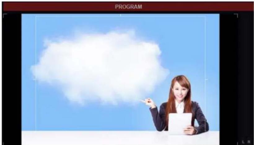
The TVS-3000 system allows users to open the Safe Frame from the “Options” drop-down menu. Once the Safe Frame function is turned on, the HD and SD Safe Frames will be shown on the PGM and PVW channels for users to confirm the HD and SD outputs on the PGM and PVW windows.
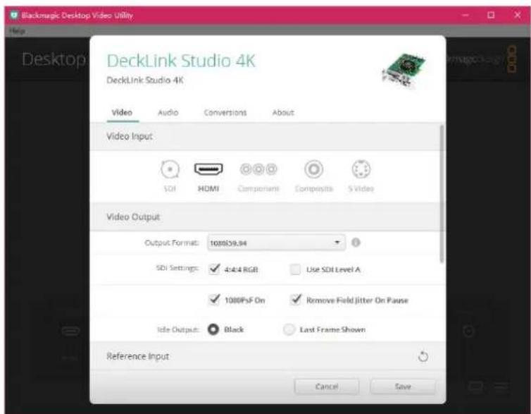
4.9.2 Capture Card Settings
In the TVS-3000 system, users can use the Blackmagic Desktop Video Utility for changing the interface settings.
4.9.3 Project Files for the TVS-3000
The TVS-3000 uses "File" button for creating, opening, saving and saving as functions for all of your engineering settings.
4.10 Multiview
Users can check the checkbox in the General Configure settings window and the default Multiview picture will be output to the second monitor which is set to be the extended monitor for the system.
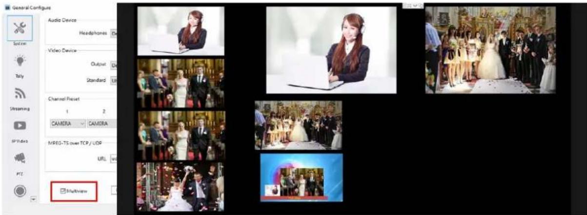
Users can select the "User" from the "Multiview Layout" option from the "Options" dropdown menu.
![Options Help General Configure User Language Activity Data Safe Frames Blackmagic Desktop Video Utility Multiviews Layout Streaming Settings PTZ Control Settings IP Video Settings Subtitle Editor SD 720 1050 4K Macros [R] TITLE 2 93629215 MONO SPORT PGM ✓ USER](/content/2026/05/830674/images/30fdaed2555b65d09114782b39eff339618a352ea60a508ef918ca13ec5a86be.jpg)
The TVS-3000 system will open a subtitle editor for users to set a multi-window combination to show the channels which users want to monitor in the Multiview monitor. Users can set the size of each window as their desires.
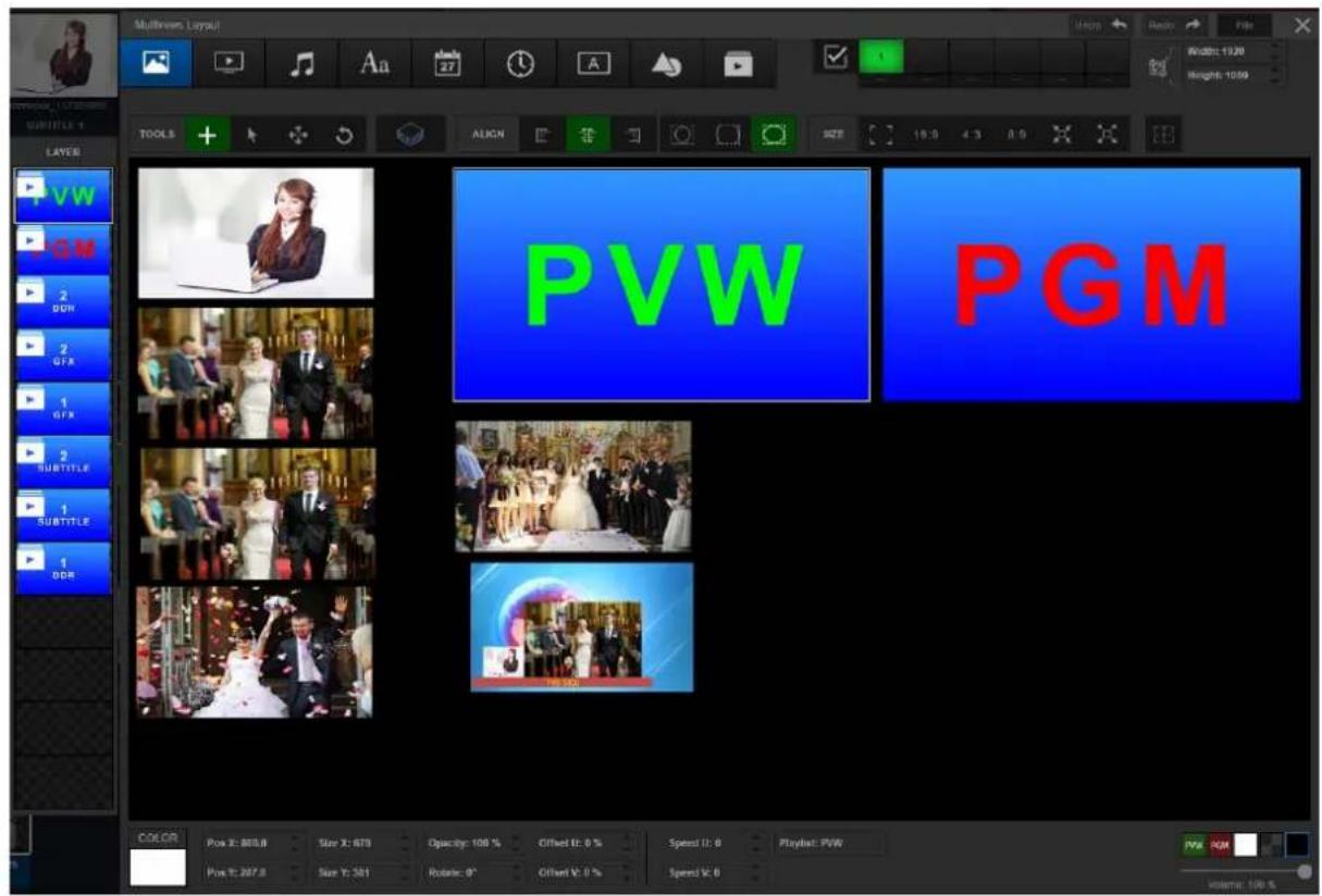
4.11 PTZ Control
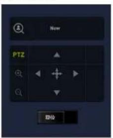
For the TVS-3000 system, if there is a PTZ camera which is connected to the same network as the TVS-3000 system or is connected to the TVS-3000 system by the RS interface, users can use the touch pad which is in the TVS-3000 GUI for controlling the PTZ camera.
Please click the "General Configure" from the "Options" drop-down menu to open the "General Configure" window. After that, please click the PTZ button to show the PTZ camera settings window which is shown as following diagram.
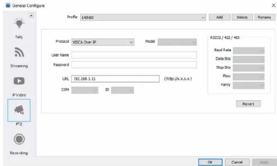
The TVS-3000 supports network connected PTZ camera operation through CGI, VISCA, ONVIF, Pelco D and Pelco P control protocols. Moreover, it also supports PTZ camera operation through RS-232, RS-422 and RS-485 interfaces. Please add a new setting and then please enter the information of your PTZ camera into the list.
The video/audio signals from the PTZ camera can be input from the SDI/NDI interfaces or from the RTMP/RTSP channels. Please make sure that those signals are added to the "CAMERA" or "NET" categories and then please right-click the meida tag of the "CAMERA" or "NET" category.
When this camera signal is selected, users can find the word "PTZ" from the touch pad for controlling. This shows that it is ready for users to use the touch pad to control this PTZ camera.
4.12 AMF Format
The transition effect or the image sequence of the CG template can be used by the TVS-3000 system. However, it will occupy too much graphic memory for the graphic card. For those materials, TVS-3000 provides a built-in converter for shrinking their size and the resource consumed.
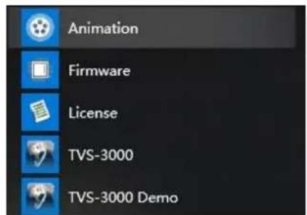
Please open the Animation tool from the software folder which is shown as following diagram.
Please click the "Video" button which is located on the top left side of the window of the converter to select the file which is needed to be converted.
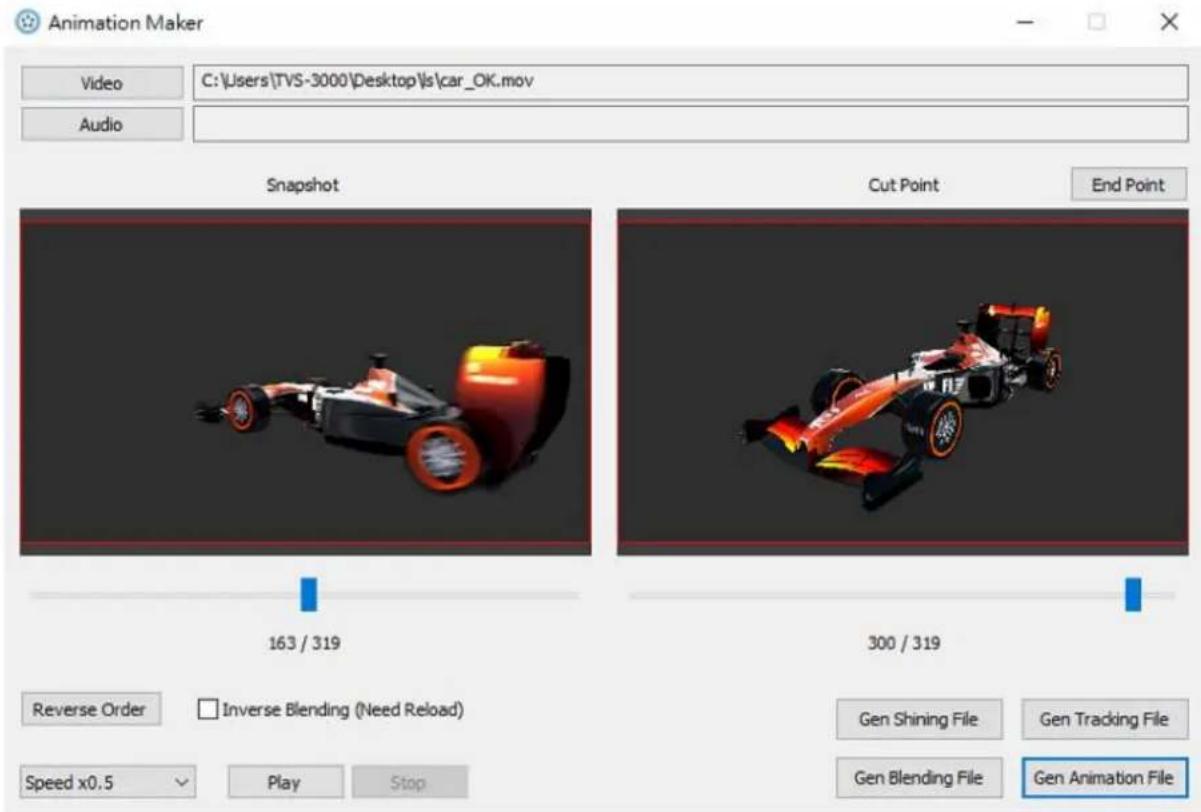
Please adjust the slider which is located below the left window (snapshot) to set the thumbnail of the animation. Please adjust the slider which is located below the right window (point for switching) to set the end point for applying the transition. After that, please click the "End Point" button. After the adjustment is finished, please click the "Generate" button for saving the outcome to your desired location. After that, users can loading this .amf file in the CG editor for the special effect for transition.
4.13 Recording and Playing of Macros
The TVS-3000 provides built-in Macros for recording a series of operating actions into one macro for achieving one-click execution. This helps users to save time for operating and adjusting in daily recording operation. Moreover, it can assure the accurate program flow timing mainly by two steps including macros recording and playing.
4.13.1 Recording for Macros
Please select the last option “Macros” from the “Options” drop-down menu for opening the MACROS recording window. The window which is located on the left side is the default location of Macros. The window which is located on the right side includes specific steps for each Macro, the window can record for maximum 16 steps.

Please click the blank area from the left side window for entering the default name of the Macro. After confirmation, the recording of the Macro will be started automatically by the system.
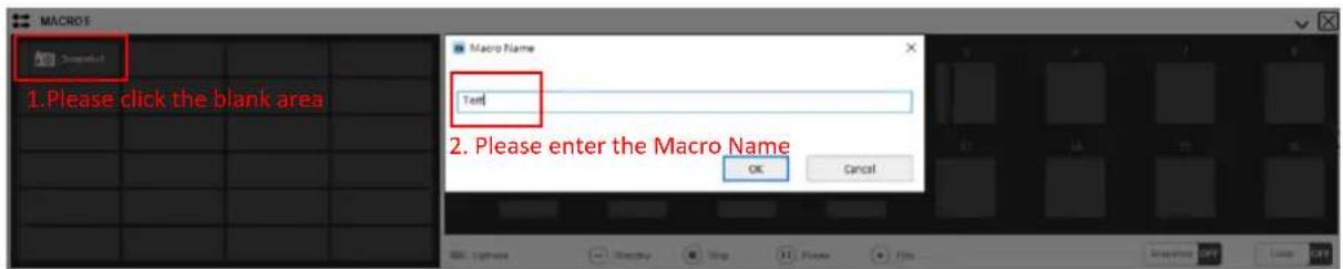
The Macros function supports content recording including channel switching, virtual camera position switching, displaying and hiding of the package. Before recording the Macro, it is necessary for users to prepare the needed materials, packages and signal sources etc., in advance.
![Macro Recording [0:01:00.83] Total Elapsed Time "Test" 1 Current Step Stop Recording Button](/content/2026/05/830674/images/4102e3af76ceb0a26b81b9356789d18a0d2d3b9a00f8622ec0fb3847423bc940.jpg)
After the Macro recording procedures are finished, users can see each recorded step from the right-side window. Users can point the figure in the round icon and then click the up-arrow and down-arrow to adjust the time interval length between each step.
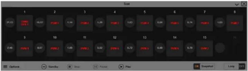
Users can do the modifying, removing, loading and saving as operations for current macro from the quick menu.
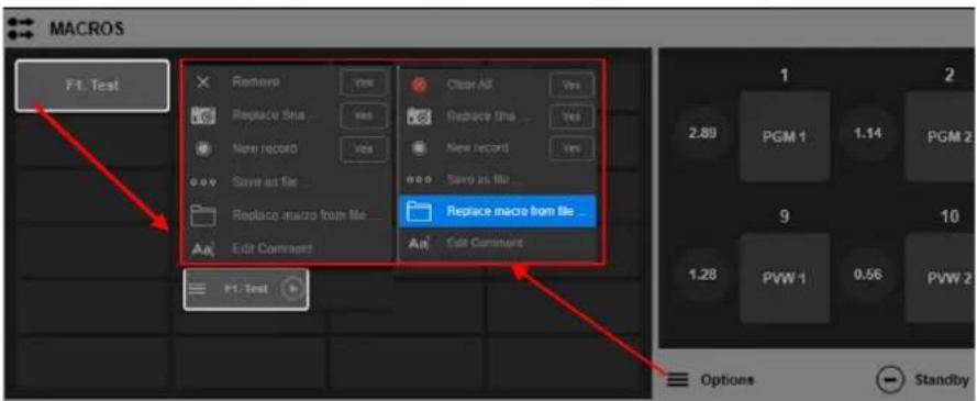
For macro testing and modifying, please click the “Standby” button which is located below the macro records for restoring the interface back to the snapshot situation, which is the initial situation. After that, please click the “Play” button for launching a series of operations for last modified and adjusted macros. During the process of playing, users can press the “Stop” or “Pause” button for stopping or pausing the playing.

When the “Snapshot” Mode is OFF and the macro is executed, it will not be forced to be started from the “Snapshot” situation. The recorded operation steps will be executed according to the material state at the time of execution.
The “Loop” mode allows users to go back to the initial state of the snapshot once the current macro is executed to the last step and finished. It will be started again until it is stopped manually.

4.13.2 How to Run a Macro
Please click the chain icon which is located on the lower left side of the switching channel preview area to open the switching channel menu. After that, please select “Macros” to open the “Macros” playing menu.
![Macros Channel [M]: Mating [M] Object [J] Capland [T] Scoreboard [S] Beauty [E] Object [O] Macros [G] PI Test 1 Please click "Macros" or press the hockey "G"](/content/2026/05/830674/images/a429e3b384da42ee3bf5bf94558aceea32755cdea00ed72cd8ae3ffbaefcbd53.jpg)
From the pop-up window, users can see the pre-edited and saved macros list. Please move the mouse cursor to the macro tag which is the one to be executed. After that, please click the playing button which is located on the right side of the tag. At this time, the software will resume the snapshot of the macro to its initial state and it will start to run the recorded operations in a step by step way. The progress bar in the window will show current progress and current step of the macro and also it will show the left time for reaching the next step operation.
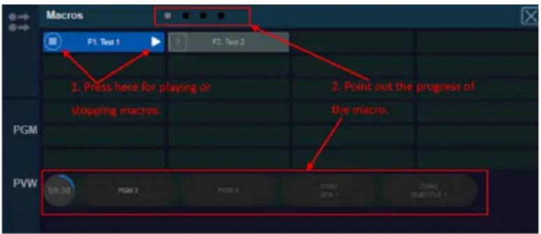
The sequential playing of the macros allow users to excute many macros to finish a series of operations. At first, please click the square frames which are located on the left side of the tags for many macros. System will number those macros according to the order of clicking. The initial number is 1 and if users click again, the numbering will be cancelled. After the numbering is finished, please press the playing button of the macro No. 1 and then the system will play all macros in sequential. After the last macro with number is executed, it will go back to macro No. 1 for continuing execution.
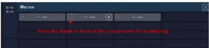
4.14 Tracking, Virtual Studio and AR Functions
The TVS-3000 integrates a built-in docking function with the HTC Tracker tracking system. When users install the HTC Tracker on the camera, the TVS-3000 can obtain the movement of the camera within the 3D space for bundling with the virtual camera lens for realizing the tracking effect of the virtual studio. When the HTC Tracker is bundled with the AR object, it can realize the real-time control of the interaction effect between AR objects and the host.
4.14.1 Installation of the HTC Tracker and the Camera
a. Installation of the HTC Base Station: The HTC Tracker must be used with the Base Station for realizing the update and tracking of the position of the HTC Tracker itself. What HTC Tracker needs to do is to connect to power source and it is no need for the HTC Tracker to connect to the main unit of the TVS-3000. The communication between the Base Station and the Tracker is by infrared. So, please make sure that there is no covering between the Base Station and the Tracker. At the same time, the effective range of the HTC base station on the Tracker is a cone-shaped area with a frontal angle of 120^ and a side length of 5m. The Tracker must move within this range. In order to increase the effective moving space of the Tracker users can use more Base Stations for forming a coverage. Users can use up to 4 Base Stations for assisting the positioning of the Tracker at the same time.
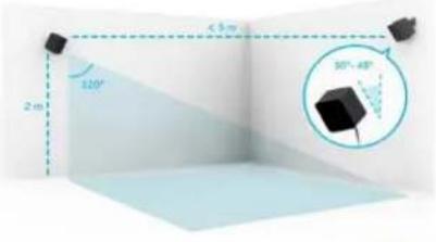
b. The Connection between the HTC Tracker and Your PC: In order to track the movement of the camera, to measure the height of the ground and to bind with the AR object, it is necessary to use at least 2 HTC Tracker for realizing the function of the Tracking/AR Virtual Studio. One of the HTC Tracker is used for binding the camera and the other HTC Tracker is used to be the ground plane reference and the AR object. The HTC Tracker can connect to PC through cable or wireless connection.
When the HTC Tracker is connected by cable, if the battery of the Tracker is charged to the power required for operation, the indicator of the Tracker will change to white, please press and hold the blue button which is located at the center of the Tracker for about 3 seconds and then wait until the indicator is shown in green, the HTC Tracker is connected to the Base Station successfully.
When the wireless connection is used for the first time, users need to pair the Tracker with the corresponding USB dongle in the packing box. For connecting the USB data cable and the wireless receiver, please press the blue button which is located at the center of the Tracker for about 3 seconds for turning on the Tracker. After that, please long-press the Logo button for about 3 seconds. The status light will be shown in blinking blue during the pairing progress of the HTC Tracker. After the HTC Tracker is paired successfully, the status light will be shown in solid green. After the pairing is finished, The Tracker can operate normally within the TVS-3000 software.
If the connection is successful, the reminder for the Tracker quantity will be shown within the small triangle which is located at the top-center of the interface. No matter the Trackers are connected in cable or in wireless, if the number which is shown is less than the Tracker which are used, please confirm that whether those Trackers are within the coverage of the Base Station. If the answer is Yes please move those Trackers to make sure that each Tracker can be recognized by the software.

c. How to install the HTC Tracker to the Tracking Camera: Due to the fact that the HTC Tracker is used to locate the camera movement, it is necessary for the HTC Tracker to has fixed mutual position/direction relationships with the camera, it is necessary for users to follow following two rules for installing the HTC Tracker and the camera which is needed for tracking.
- Please make sure that the bottom surface of the HTC Tracker must be paralleled to the horizontal plane of the camera.
● Please make sure that the USB port of the HTC Tracker must be faced to the direction which is the same as the rear of the camera (which is shown as following diagram)
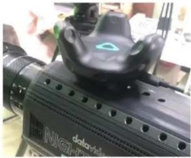
natural_image
Close-up of a black H1NIGHT vehicle with a circular sensor on top, displayed indoors (no visible text or symbols)4.14.2 Data Test of the Camera Lens
In order to make sure that the real camera lens situation with the HTC Tracker is consistent to the situation of the virtual camera lens, it is needed to calibrate the currently used camera, its corresponding camera lens and camera parameters. For the camera lens and camera combination which is not used for shooting, it is needed for it to pass some sets of the data test for generating new parameters for loading into the software.
a. Measure the Relative Position of the Tracker and the Camera: The center of the bottom surface of the Tracker is the location point of the Tracker. The center of the front lens of the camera lens is the location point of the camera. It is needed for users to measure the offset distance between the two points in the left and right, up and down and front and rear directions. Those three offset distances must be recorded as X, Y and Z respectively. Please see following paragraph for the positive and negative rules of the values.
When a person stands behind the camera and faces to the same direction as the camera lens. At this time, if the HTC Tracker is located at the left side of the camera lens, the X will be a negative value. If the HTC Tracker is located at the right side of the camera lens, the X will be a positive value. If the HTC Tracker is located under the camera, the Y will be a negative value. If the HTC Tracker is located on the camera lens, the Y will be a positive value. If the Tracker is located in front of the center point of the camera lens, the Z will be a positive value. If the Tracker is located behind the center point of the camera lens, the Z will be a negative value.
b. Measure the Distortions of the Camera Lens and the Camera: To measure lens distortion, a standard checkerboard calibration board with a size of 25mm X 25mm is required. Or users can paste the 25mm checkerboard pictures on a hard plate. After that, please change angle and distance in front of the camera and then capture at least 20 or more pictures. Before capturing pictures, please make sure that the camera lens is set to minimum focal length.
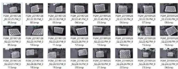
Please guide those pictures into the Camera Calibration Tool of the Matlab software.
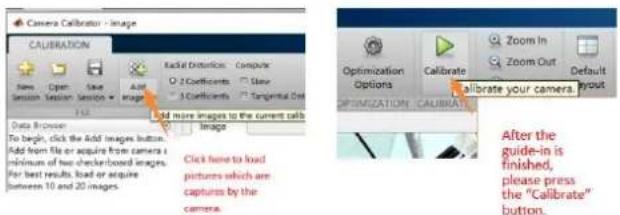
After the calculation is finished, please click the tick button to export the outcome of the calculation and then please go back to the main interface of the Matlab to copy the outcome of the calculation to a .txt file for saving it.
![Click here to export the outcome of the calculation. cameraParameters Camera Intrinsic IntrinsicMatrix: [3x3 double] PocallLength: [1.8246e+07 1.8239e+03] PrincipalPoint: [879.0574 819.2360] Show: 0 Lens Distortion RadialDistortion: [-0.1945 0.0000] LongantialDistortion: [0 0] Camera Retrains RotationMetrics: [3x3x25 double] TranslationVectors: [35x3 double] Accuracy of Estimation MeanReprojectionError: 0.8304 ReprojectionErrors: [94x2x25 double] ReprojectedPoints: [94x2x25 double] Calibration Settings NumPatterns: 25 WorldPoints: [54x2 double] WorldUnits: mm EstimateView: 0 NumRadialDistortionCoefficients: 2 EstimateFangentialDistortion: 0 Please copy this and then paste it to a blank .txt file for saving it.](/content/2026/05/830674/images/9326c7835a6f61b256a18004739638cf740a80b9e936a8c68cee1d6a59243e7a.jpg)
c. Use the calibration tool to generate the combined parameter file of the camera and camera lens combination: Please open the "LensSpline.exe" tool from the software file folder. After that, please click the "Load Calibration Files" button which is located on the bottom left side to load the .txt file which is saved in the previous step.
After that, please enter the minimum and maximum focal lengths in the “Lens Mount(mm)” blanks which are located at the left side. And then please enter the measured X, Y and Z values which are measured from the step a. into the X,Y and Z blanks which are located at the right side.
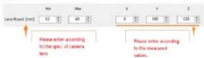
After those values are filled, please click the "Save as" button which is located at the top-right side of the window and then please save the parameter file into the "Calibration" file folder which is located in the file folder of currently used software version.
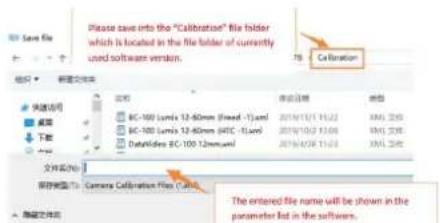
4.14.3 TVS-3000 HTC Tracker Test and Adjustment Reminders
After the TVS-3000 9231 version upgrading, the installation and the operation of the ground calibration for the HTC Tracker are greatly optimized. The positive and negative numbers rule for the parameter setting tool Lenspline is also updated. Please see following paragraphs for the explanations for the issues which are encountered by users when measuring the HTC Tracker and ground calibration.
Installing the HTC Tracker on the Camera
For the ground confirming algorithm after TVS-3000 new version upgrading, it is no need for users to place the USB interface of the HTC Tracker on the same direction as the rear side of the camera. This improvement avoids the difficulty in installation and use caused by the difficulty in determining the direction of the usb interface when the fixing fixture is tightened. Users can tighten it as much as possible. However, since the camera attitude must be confirmed by the attitude of the HTC Tracker, it is a must that the bottom surface of the HTC Tracker on the camera must be paralleled to the horizontal plane of the camera. When installing the HTC Tracker, please make sure that there is no pitch and skew for the left, right, front and rear directions of the HTC Tracker when comparing to the camera for assuring the tracking accuracy.
The Measuring and Entering of the X and Y Values
Generally speaking, the position which the HTC Tracker is installed is mainly on the left and right axis of the camera. So, in the new version of the Lenspline tool, it deletes the distance data of the X-axis offset. What users need to do is to measure the up and down distance (Y value) and the front and rear distance (Z value). The positive and negative determining rule for the entered number is that if the HTC Tracker is on the camera, the Y value will be a negative number. If the HTC Tracker is among the camera lens and the rear side of the camera, the Z value will be a positive number. Generally speaking, users will install the HTC Tracker according to the above-mentioned way. So, basically, the Y value will be a negative number and the Z value will be a positive number. Please pay attention that the number here is written in the unit of mm. For measuring, please pay attention that the camera lens must be rotated to its widest angle focal length when measuring the front and rear distances between the HTC Tracker and the camera lens. Please measure the tracker installation fixed point, which is the tracker center axis, to the left and right position of the first lens closest to the front end of the lens.
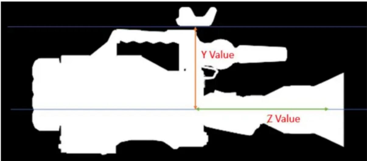
Important Reminder for Measuring Checkerboard
The checkerboard measurement is to measure actual picture distortion when the camera is combined with the camera lens for synchronizing the edge distortion when the camera lens is operated at the widest angle focal length. So, it is important for the measuring accuracy for this step. If a finished calibration board is used, please make sure that the calibration board model No. is GP340-12*9. If the calibration board is printed by the A4 paper, please make sure that the calibration board is printed according to original size. On the printed result, the size of each grid is exactly 25mm. Moreover, please pay attention that the printed calibration board must be laid on a flat surface that will not deform. (foam board, acrylic board, etc.),
Please do not have undulation or crumple on the paper. When measuring screenshots, try to choose as many as possible the state where the oblique direction of the calibration board is more obvious. Moreover, please pay attention for taking screenshots of the calibration board close to the four sides of the screen.
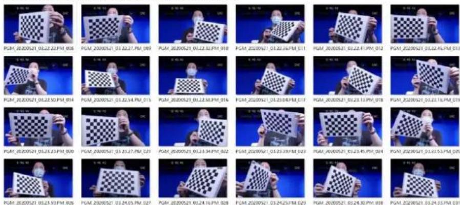
Wake-up of the HTC Tracker and the Confirmation of the Operating Status
When the HTC Tracker is operated in wireless status, generally, the LED indicator will be shown in blue. After entering the operating status, the LED indicator will be shown in green. If the color of the LED indicator is wrong, users can long-press the blue button which is located at the center for turning off the HTC Tracker. After the LED indicator is turned off, please press the blue button for turning on the HTC Tracker and then please shake the HTC Tracker a little bit within the coverage of the Base Station until the LED indicator is changed to green for normal operation. When the HTC Tracker is connected by cable, the default priority is to search the PC which is connected to the HTC Tracker. So, if you just want to charge the HTC Tracker, please do not connect the USB cable to your PC. What you can do is to connect a charge-only USB cable after the HTC Tracker is operated in wireless mode and the LED indicator is shown in green. The only difference is that the other side of the USB cable is not connected to your PC. The LED indicator should be kept in green and can operate normally.
When the HTC Tracker is operated by connecting to a cable, if users connect a USB cable to the HTC Tracker when it is turned off and the LED indicator is not shown in any color, the LED indicator will be shown in orange(means the HTC Tracker is in charging) or shown in white (mans the HTC Tracker is fully charged). If users press the blue button at this time, the LED indicator will be shown in blue. If the TVS-3000 software is launched at this time, please shake the HTC Tracker a little bit at this time and then the LED indicator will change to green.
The Confirmation for the Direction of the Virtual Scene
When the virtual scene is loaded for the first time and the HTC Tracker is connected for positioning, the direction of the virtual scene is synchronized with the direction of the real environment. Subject to the base station. The direction of the base station numbered b is the direction that the front view looks when the scene is built in 3Dmax. The ground plane point of the Base Station numbered B is the original point for the X coordinate and Z coordinate when the virtual scene is built in 3Dmax. So, if the Base Station is placed on the left side of the
camera when it is installed, the initial virtual camera lens position will face to the right side of the virtual scene. In order to confirm the size and the situation of the virtual scene, users can turn the direction of the camera to the position which the number B Base Station is located. And then users can see the default front view camera position of the virtual scene in normal non-tracking situation from the virtual scene channel screen of the TVS-3000.
The Adjustment for the Direction and Size of the Virtual Scene
In order to adjust the virtual scene to face forward, users can press the rotation button which is located on the bottom-right corner of the offset adjustment board when adjusting current tracking virtual scene. Please pull the rotation button to adjust the orientation and please press and hold and then pull the cross-shaped button which is located at the center of the offset adjustment board to each direction for adjusting the virtual camera position in the virtual scene. Please pay attention that the front side, rear side, left side, right side and direction must be adjusted according to the virtual scene space. So, when you pull the cross-shaped button to the front, rear, left and right sides, please do not determine the direction according to the front, rear, left and right sides of the virtual scene channel on the screen. Users should adjust the direction based on the virtual orthogonal view on the left side of the Offset Adjustment Board.
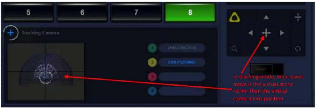
4.14.4 Camera Tracking and Binding
a. Preliminary Step: After opening the TVS-3000 software, the system will test the quantity of available Tracker and then the quantity will be shown at the center of the triangle icon which is located on the top-left side of the GUI. Please make sure that whether there is a difference between the quantity of needed Tracker and the detected Tracker. If there is a difference, please check according to the settings in the 4.14.1 section. In order to ensure the precision of the tracking, please confirm that the anti-shake function of the camera is turned off. After that, please load the camera signal into the switching channel for further chromakeying. Please load the needed virtual scenes by using the GFX or BUFFER switching channel. It is no need for users to bind the camera signal to the A, B, C, D objects which are located in the virtual scene. b. Virtul Scene Binding: Please select the loaded virtual scene and then please click the cross-shaped icon on the top-left corner of the virtual camera lens area. After that, the top-left corner of the Offset Adjustment Board will show “VR”. Please click “VR” to open the menu for selecting the Tracker which is mounted on the camera for binding.
Note: When the new device is selected for the first time, it is possible that the corresponding Tracker No. may not be confirmed. Users can select a Tracker randomly for binding. After the binding is finished, users can shake the camera after binding to see whether the virtual camera lens can follow or not. If the answer is No, try to bind another Tracker for confirming whether the correct Tracker is selected or not. Users can write down the corresponding No. for the convenience of future application.
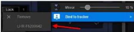
After the Tracker is binding successfully, the VR button will be shown as a yellow triangle. Please click the yellow triangle to open the menu for entering into the camera synchronization option to select the loaded camera signal.

Click the yellow triangle again for opening the menu. In the camera calibration menu, please select the pre-tested and saved camera parameters (c section in 4.14.2) or you can select the existing corresponding parameters for the camera or camera lens which is used in real application.
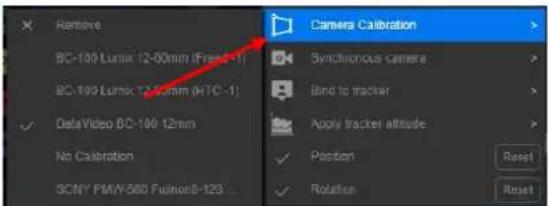
C. Ground Positioning: After the above-mentioned adjustment, the binding between the virtual camera lens of the virtual studio and the HTC Tracker which is located on the real camera is done. Users can move or rotate the real camera for moving or rotaing the virtual camera lens. In order to adjust the height of the virtual camera to be the same as the real camera, users can place the other HTC Tracker on the ground. After that, please press the yellow triangle button and then press the reset button on the right side of the Tracker from
"Positioning to Ground Plane" from the menu. Please operate according to the reminder of the system to adjust the cursor of the camera to be aligned to the HTC Tracker Logo which is placed on the ground. After that, please click "confirm" and then the ground height of the virtual scene will be synchronized to the ground height of the real scene.
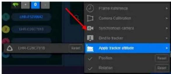
Tip 1: If there is no change for the height of the real ground plane, users can click the “Apply tracker attitude” for one time. However, please pay attention that during the process of tracker attitude synchronization, please make sure that there is no shield between the Tracker and the Base Station and the Tracker can be recognized correctly.
Tip2: The Tracker which is placed on the ground can be placed in any direction. However, please make sure that the bottom of the Tracker is close to the ground.
d: Synchronization Adjustment: Due to the fact that some cameras may need longer time for processing signals for pictures, it will cause the unsynchronization issue between the screen which is shot by the real camera and the movement of the virtual camera lens in the TVS-3000 software. Users can try to adjust the “Frame Reference” parameter and then turn the real camera direction to the left side and the right side to observe the situation of the virtual camera movement and the situation of the real camera until the movement of the virtual camera lens is synchronized to the screen which is shot by the real camera. If the movement of the virtual camera lens is faster and the movement of the real camera lens is slower, user can select the positive number, if the virtual camera lens is slower and the real camera lens is faster, users can select positive number for synchronization.

4.14.5 Position Adjustment
a. The confirmation rule for the relative position of the tracking camera lens: In order to obtain the basic relative coordinates, after the TVS-3000 binds the virtual camera to the Tracker, it will synchronize the virtual scene space with the real space where the base station and the Tracker are located according to the basic spatial location rules. Moreover, this relative position will determine the direction of the virtual camera lens which is bound by the Tracker and the distance which is relative to the virtual scene. When making the virtual scene, the center of the coordinate axis(0 point of the X axis and Z axis) where the virtual scene is located will be determined by the position of the Base Station on the ground plane. The direction of the Base Station determines the direction of the virtual scene. From the angle of the Base Station, the front side of the Base Station is the front side of the virtual scene(please refer to following diagram). Users can refer the following diagram to determine the position of the camera and the Base Station. After the virtual camera lens is binding to the Tracker, users can see from the default view angle which the virtual camera is faced to the subject of the virtual scene. Otherwise, users need to adjust the orientation of the virtual scene manually. The unit size which is selected when using the virtual studio will correspond to the size of the real space.
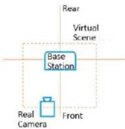
b. Adjust and Modify the Tracking Position: If there is a difference between the virtual scene size/direction of the camera and users' real need, users can use the moving, rotating and scaling tools in this area for adjusting the scale between the real subject which is shot by the camera and the virtual scene. Users can switch it to the PVW/PGM windows for monitoring and can also use the floor plan which is located on the virtual camera lens area for further confirmation.
![Tracking Camera - DeckLink JK Pro [1] Show the floor plane of the virtual scene. 2516 : X -1153.3 Y 2317.1 Z 0:00 : F 76.85 : H 2.55 : P 0.52 : B 0.0 : G Show the direction where the virtual camera is faced.](/content/2026/05/830674/images/70b726813d6243f8e6d83b66234b2f915f67bc64c434e6e5eefddd455e5429f7.jpg)
4.14.6 Binding of the AR Object
We can use the Tracker which is used for positioning the ground plane to bind a virtual object for realizing the real-time control of the effect for the AR 3D object interaction.
a. Loading the virtual object: please select and open the switching channel which is used for tracking the virtual scene. Please load the AR object from the by TVS-3000's DSK Overlay Layer Window. Please click the "plus" icon which is located on the top-left corner of the layer window and then please click "Open File" for loading the needed AR object.
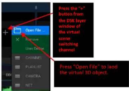
b. Binding the AR virtual object with the Tracker: After the AR object is loaded, please click the object name which is located below the corresponding DSK overlay window for showing the object. After that, please click the cross-shaped icon which is located at the title column. And then the controlled object of the “Offset Adjustment Board” area will change to the AR object of current DSK overlay layer.
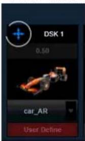
Please click the “3D” icon which is located at the top-left corner of the “Offset Adjustment Board”, and then please select the Tracker which is bound. The operation is the same as the procedures for binding the virtual camera. The disorder parameters and Frame synchronization for binding the virtual camera will be applied automatically and it is no need for users to do more selection. After the virtual object is bound, if the Tracker which is bound with the AR object is shown within the shooting range of the real camera, the TVS-3000 system will show the AR object in the virtual scene according to its position in the real space. However, please pay attention that the AR object can be shown in front of the host only and the front-rear relative relationship of the host and the AR object can not be changed through changing the position of the Tracker.
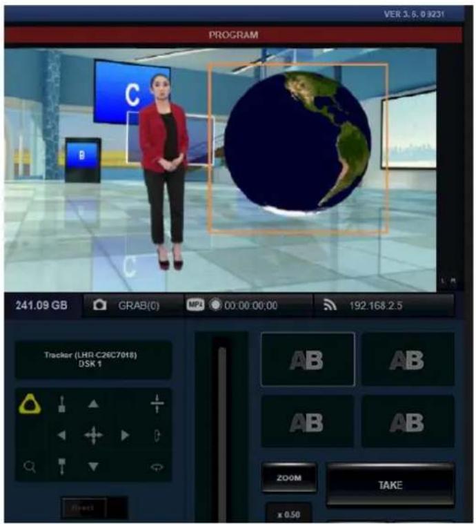
c. Use the controller to control the virtual object: If the object which is used to bind the AR object is the HTC VIVE Controller, users can use the buttons on the handle to control the enlarging, shrinking, positioning and hiding of the AR object except the Tracker function. The corresponding button of the HTC VIVE Controller is shown as following diagram.
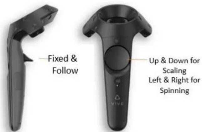
Chapter 5 How to Set the Blackmagic Desktop Video Setup
When you open the Blackmagic Desktop Video Setup for the first time, the main interface will show the hardwares which are connected. Moreover, this interface will show the operations of all videos for all of the input and output interfaces for all of your hardwares. If the video signal is sent to the input interface, the system will detect that signal automatically and then the format of that signal will be shown below the Video Input icon. If there are many Blackmagic capture and playback devices which are connected, press the arrow buttons which are located on both sides of the main interface will show all devices sequentially.
If you want to set those devices, what you should do is to click the hardware icon or click the settings icon which is located under the hardware name. The Desktop Video Setup software shows devices which are related to the selected hardware only. The main interface and the setting interface for the Blackmagic Desktop Video Setup are shown as following diagram.
Main Interface:
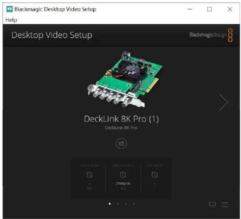
Setting Interface:
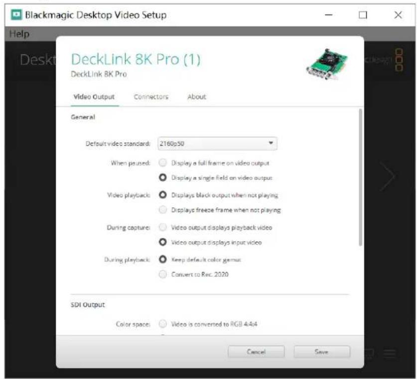
5.1 Video Output
The frame rate and the frame of the output video are determined by the engineering settings of the TVS-3000 software, it is OK to keep the default settings here.
Note: If you want to output the 4K output signal through the SDI interface, it is necessary to use Nvidia Quadro P5000 or the same grade graphic card. The color space for the TVS-3000 HD/UHD SDI output is 4:2:2 and the color space for the HDMI output is 4:4:4.
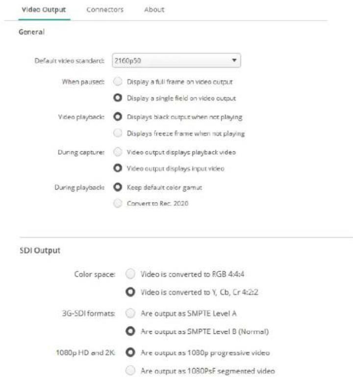

5.2 Connectors Mapping of the DeckLink 8K Pro
Blackmagic DeckLink 8K Pro allows users to set the connector mapping of each SDI interface. The interface for the connectors mapping is shown as following diagram.
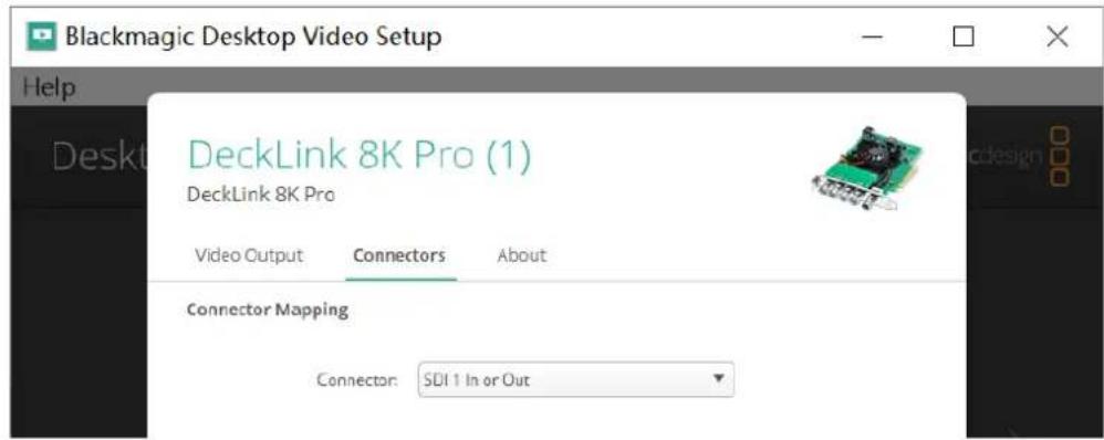
- Users can modify the setting of the 8K Pro to 4 inputs or 4 outputs which is shown as following diagram.
Connector Mapping

- Users can also set the function of each connector respectively which is shown as following diagram.
Connector Mapping

Mapping Options for the DeckLink 8K Pro
| DeckLink 8K Pro Devices | Dedicated SDI Interface |
| DeckLink 8K Pro (1) | SDI 1 |
| DeckLink 8K Pro (2) | SDI 3 |
| DeckLink 8K Pro (3) | SDI 2 |
| DeckLink 8K Pro (4) | SDI 4 |
There are some ways in the software for defining the connectors, users can set related parameters according to their needs.
| Options in the Software | Explanations |
| SDI 1 & 2 In, SDI 3 & 4 OutSDI 1 to 4 In or OutSDI 1 In, SDI 2 OutSDI 1 In or Out | Overall Setting, 4 connectors, 1 & 2 are Input connectors and 3 & 4 are Output connectors. |
| Overall Setting, all of the 4 connectors can be input or output connectors. | |
| Set SDI 1 to be the input connector and SDI 2 to the output connector only. | |
| Set the SDI 1 to be input connector or output connector only. |
5.3 DeckLink 8K Pro Connectors and Corresponding SDI Numbers on the Rear Panel of the TVS-3000
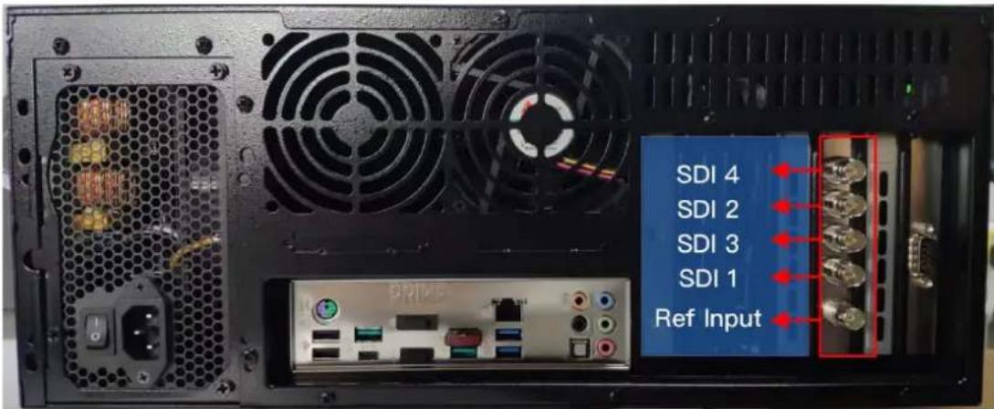
Chapter 6 Graphic Card De-interlace and Graphic Card Memory Usage Issues
6.1 How to set the Graphic Card De-interlance Settings
Please follow following settings for setting the de-interlace setup of the graphic card.
Step 1: At first, please right-click the mouse from the desktop of your PC to select the "Nvidia Control Panel".
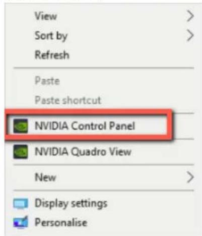
Step 2: Please select "Adjust video image settings" from the menu and then please uncheck "Use inverse telecine". Finally, please click the "Apply" button to finish the setting.
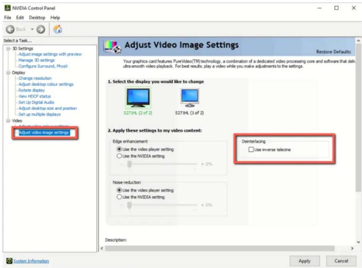
6.2 How to Solve the Graphic Card Memory Usage Issue
For current situation, if the TVS-3000 software settings are modified and after the software is relaunched automatically, the occupied GPU memory when loading the virtual scene for the last time will not be released automatically. When the engineering file is loaded again, users will find out that the RAM situation will be shown in red which is shown as following diagram.
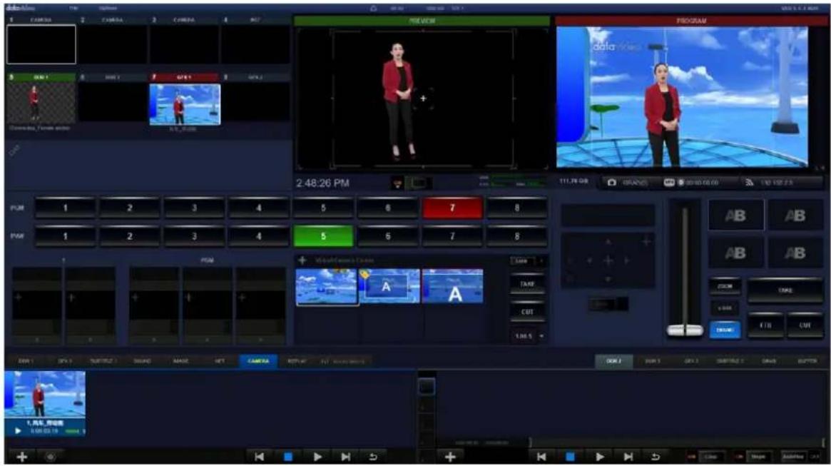
How to solve this issue: Please close the software manually. At this time, the software will release all occupied memory cache. After the software is launched again, users can load the virtual scene directly which is shown as following diagram.
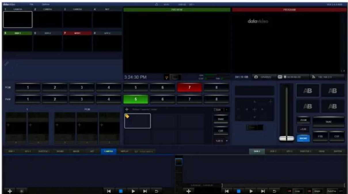
6.3 Important Notice When Connecting the TVS-3000 to an External Connected Monitor
Please remember that when connecting the TVS-3000 to an external connected monitor, it is a must to connect to the output interface of the TVS-3000 graphic card.
Chapter 7 Hotkeys List
| Button | Function |
| Number Key 1-8 | Select the Channel 1 to Channel 8 to the PWM monitoring window |
| Ctrl + F1 - F8 | Select the Channel 1 to Channel 8 to the PGM output window. |
| Ctrl + 1-8 | Select the Channel 1 to Channel 8 to enter into the adjusting mode, the white frame will move to the corresponding preview window. |
| Left Shift + 1-6 | Transition to the virtual camera lens 1-6 with panning and tilting. |
| Right Shift + 1-6 | Switch to the virtual camera lens 1-6 directly without any transition. |
| Left Shift + 9,0,-,L,O,P | Switch to the virtual camera lens 1-6 with panning and tilting transition. |
| Right Shift + 9,0,-,L,O,P | Switch to the virtual camera lens 1-6 directly without any transition |
| Enter | Switch the PVW signal from the PVW monitoring window to the PGM window with transition effect. |
| Space | Switch the PVW signal from the PVW monitoring window directly to the PGM window without transition effect. |
| Ctrl + F10 - F12 | Cut in/cut out the contents of the DSK overlay 1-3 |
| N | Open the channel setting menu for the switching channel where the white box is located(corresponding objects for A, B, C and D). |
| M | Open the Matting menu for the switching channel where the white box is located. |
| J | Open the “Adjust” menu for the switching channel where the white box is located. |
| O | Open the “Object” menu for the switching channel where the white box is located. |
| G | Open the playing menu for the “Macros”. |
| R | Open the Macros command editing menu. |
| X | Switch the material management menu which is located on the lower side of the monitor to the audio mixer interface. |
| F | Open/Close the Safe Frame. |
| V | Switch the material management menu to large thumbnail display mode/playing list mode |
| TAB | Switch to next switching channel which is next to the channel where the white box is located. |
| A, B, C, D | Select the object A, B, C and D (will be effective when the contents of the switching channel where the white box is located are graphic & text combination or virtual scene). |
| Ctrl+I | Start/Stop Streaming |
| Ctrl+R | Start/Stop Recording |
| When in the Graphic and Text Editor | |
| Ctrl + U, Y | Resume/Cancel the last change |
| Up, Down, Let and Right. Direcion Keys for up, down, left and right. | Adjust the location of the X coordinate and Y coordinate for the selected graphic layer. |
Chapter 8 RMC-285 TVS-3000 Remote Control Panel
8.1 Introduction of the RMC-285 Remote Control Panel
The RMC-285 is a remote control panel which is designed for the TVS-3000 virtual studio system. The RMC-285 is connected to the TVS-3000 virtual studio system by the RS-232 cable. Users can feel the experience just like they are using a physical switcher when they are using the RMC-285 to control the TVS-3000 virtual system. The RMC-285 provides many control functions including DSK buttons, transition effects, streaming and recording functions. Moreover, the T-Bar gives users great convenient in switching PVW and PROGRAM screens. Furthermore, the RMC-285 provides 10 self-defined function keys for users to define their own operating regulations according to their own procedure.
8.2 Features
- Allows for Easy and Fast Control
● 100% Compatible with the TVS-3000 System
● Up to 10 Default Macros - Independent "REC", "STM" and "GRAB" Buttons for recording, streaming and still-grabbing.
● Brand New Designed Rolling Wheel Type T-Bar
● The Joystick and zoom wheel lock function can prevent the accidental touch from happening.
● Built-in PTZ camera control - Upgrades the firmware easily by the RS-232 Connection.
8.3 Control Panel
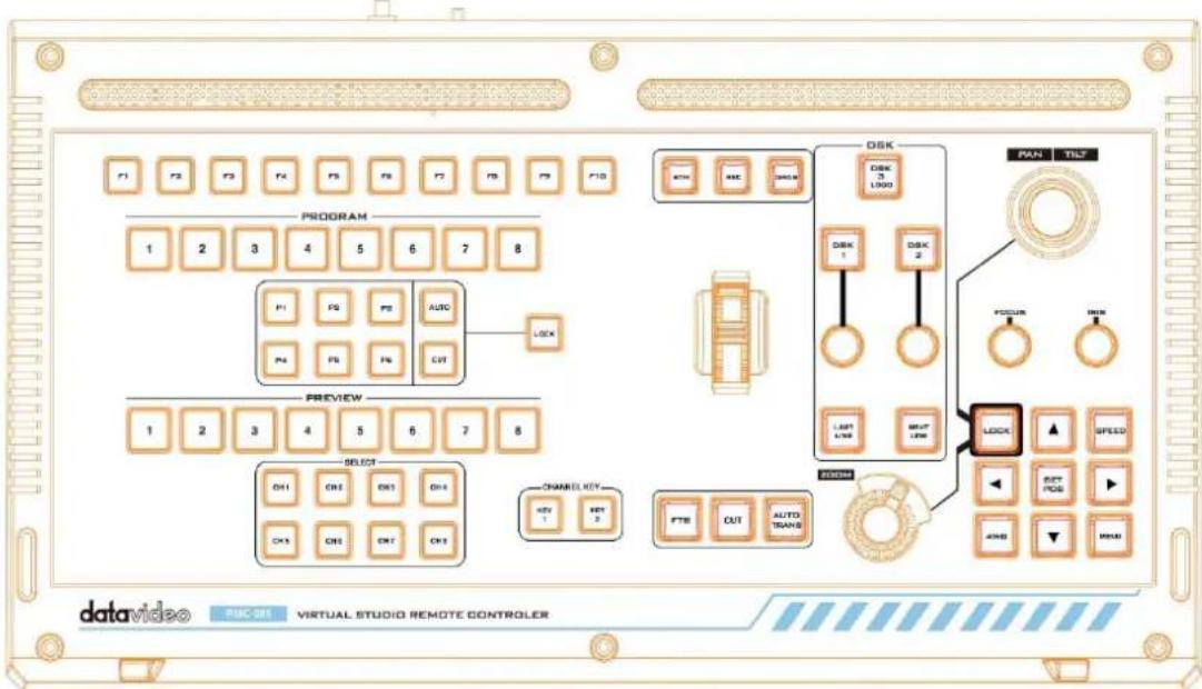
8.4 Rear Panel
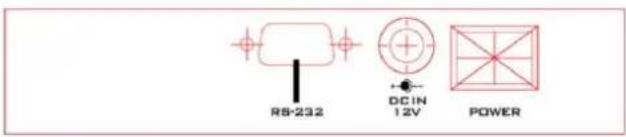
8.5 LED Color and Situation for the Control Panel Buttons
The LED color for the control panel buttons are shown in white when they are in normal operation, please see following diagram for the situations and the LED colors when those buttons are pressed.
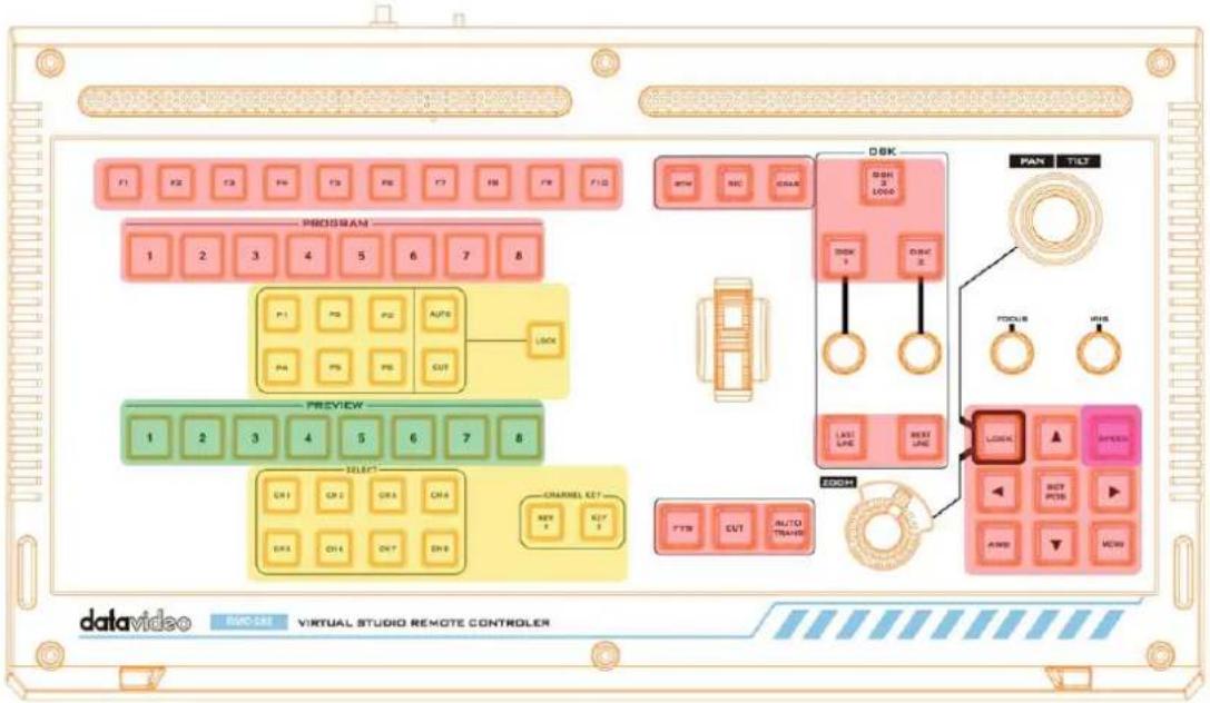
● F1-F10 Users can define those buttons by themselves according to their needs. In normal operation, those buttons will light up in white. If those buttons are selected, they will light up in red.

● PROGRAM 1-8 Those buttons allow users to control the PGM output channel in a real-time basis. If those buttons are selected, they will light up in red.

P1-P6 : Those buttons are virtual camera selection keys for users to switch between different virtual camera lens position. AUTO/CUT: Buttons for switching channels. If "AUTO" is selected, the channel will be switched automatically. If "CUT" is selected, the channel will be switched directly. "Lock" is the lock button. If the "Lock" button is used, the virtual camera lens position buttons and channel buttons can not be used. If those buttons are selected, they will light up in yellow.
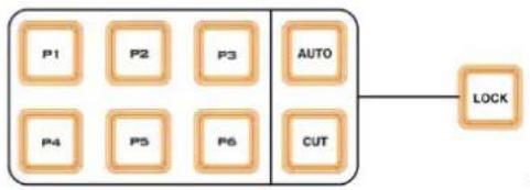
flowchart
graph TD
    P1[" P1 "] --> AUTO[" AUTO "]
    P2[" P2 "] --> AUTO
    P3[" P3 "] --> AUTO
    P4[" P4 "] --> AUTO
    P5[" P5 "] --> AUTO
    P6[" P6 "] --> AUTO
    AUTO --> LOCK[" LOCK "]
- PREVIEW 1-8 allow users to control the PVW channel in a real-time basis. If those buttons are selected, they will light up in green.

- CH 1-8 allow users to select different channel in a real-time basis. The KEY1-2 CHANNEL Key buttons can show or hide the loaded contents in a real-time basis. If those buttons are selected, they will light up in yellow.
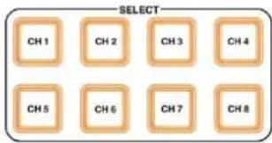
- FTB\CUT\AUTOTRANS Buttons:
The FTB button allows users to fade the screen to a black screen. If this button is pressed, it will flash in red.
The CUT button allow users to switch to next screen directly without any transition effect. AUTO TRANS is the automatic transition button and the default transition effect is "Dissolve". If there is any transition effect which is loaded, it will use that transition effect when this "AUTO TRANS" button is activated.
● STM\REC\GRAB Buttons:
The STM button is used for streaming. After the setting is finished, users can start or stop the streaming function rapidly.
The REC button is used for recording. After the setting is finished, users can start or stop the recording rapidly.
GRAB button is used for screenshoting, it allows users to capture the PGM screen rapidly.
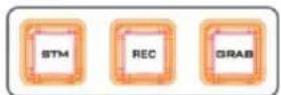
● T-Bar allows users to achieve the real-time switching for the virtual studio.
- DSK 1-3 PGM allow users to control the displaying and hiding of the contents for three DSK overlay layers.
- DSK1-2 Buttons allow users to switch the material contents in the material list rapidly.
- LAST LINE\NEXT LINE can be used with the DSK caption function for users to switch the captions rapidly.
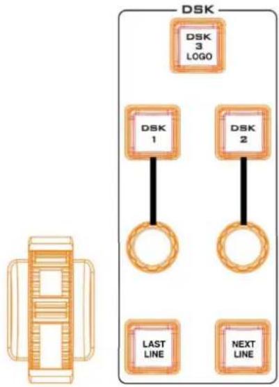
flowchart
graph TD
    A["DSK 1"] --> B["DSK 2"]
    C["DSK 3 LOGO"] --> D["DSK 1"]
    C --> E["DSK 2"]
    F["LAST LINE"] --> G["NEXT LINE"]
● PTZ Camera Control
Lock:
When the LOCK button is used, the button will be shown in red for locking 启 the Joystick and Zoom functions.
SPEED: (Three-Stage Cycle)
This button allows users to control the speed of the camera adjustment. When in low speed, this button will be shown in white, for the middle speed, this button will be shown in pink and for the high speed, this button will be shown in red.
AWB: This allows users to adjust the camera to AWB mode.
MENU: This allows users to show the camera OSD menu.
←↑→↓:
Those buttons will light up in red when they are pressed, and then output the up/down/left/right actions for one time.
When those buttons are long-pressed, it will output up/down/left/right actions continuously after half a second delay.
In OSD Menu Mode:
Press the ↑↓ buttons for browsing within the same layer.
Press the → button to go to next layer.
Press the ← button to go back to the previous layer
SET POS:
When operating the real PTZ camera, please use it with the "SET POS" button which is located on the right side.
When the "SET POS" button is pressed, the "SET POS" button will light up in red and the P1 to P6 buttons will be blinking in yellow.
When one of the P1 to P6 buttons is pressed, the camera position will be saved for Preset and after it is saved, the button will be resumed to white.
PAN/TILT:
When the Lock button is shown in white, users can adjust the rotation when it is in the scene editing mode.
When the Lock button is shown in red, please shake the joystick for the Panning/Tilting operations.
FOCUS:
When the FOCUS button is rotated in clock-wise direction, it will focus on far view
If the FOCUS button is rotated in anticlock-wise direction, it will focus on near view.
IRIS:
When this button is rotated in clockwise direction, the IRIS will become larger.
When this button is rotated in anticlockwise direction, the IRIS will become smaller.
ZOOM:
When the Lock button is shown in white, users can adjust the scaling of the virtual scene within the virtual scene editing mode.
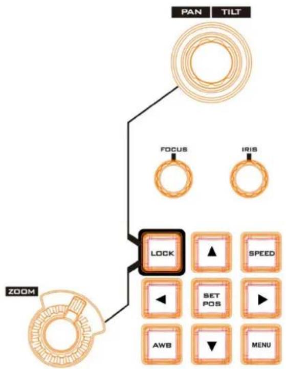
flowchart
graph TD
    A["PAN"] --> B["FOCUS"]
    C["TILT"] --> D["IRIS"]
    E["ZOOM"] --> F["LOCK"]
    F --> G["▲"]
    F --> H["SPEED"]
    F --> I["◄"]
    F --> J["SET POS"]
    F --> K["►"]
    F --> L["AWB"]
    F --> M["▼"]
    F --> N["MENU"]
When the Lock button is shown in red, it allows users to adjust the scaling of the screen which is shot by the camera.
When the ZOOM wheel is rotated in clockwise direction, the screen will be enlarged.
When the ZOOM wheel is rotated in anticlockwise direction, the screen will be shrinked.
Chapter 9 Frequently-Asked Questions
This section describes problems that you may encounter while using the TVS-3000. If you have questions, please refer to related sections and follow all the suggested solutions. If problem still exists, please contact your distributor or the service center.
| No. | Problems | Solutions |
| 1. | How to check whether the firmwares of the HTC Vive Base Station and HTC Vive Tracker are needed to be upgraded? | Users need to install the Stream VR software for checking the firmware version in recognizable devices. After that, users can know whether it is needed for upgrading the firmware or not. |
| 2 | What type of the graphic card is supported by the TVS-3000 and what version of the graphic card driver should be used? | ● Users can use the NVIDIA graphic card. However, the AMD graphic card is not supported. It is recommended to use the graphic card with 6 GB or more graphic memory. ● The NVIDIA related coding is used in the TVS-3000 software. So, it is recommended to use the graphic card driver with the version number of “430.64” or later for smooth operation. |
| 3 | What file format can be output for the virtual scenes and virtual objects which are made by the 3D software? | ● Those files can be output to be the FBX format files for packaging and guiding in to the virtual software. ● The Autodesk FBX file format is supported by the TVS-3000 system. In real testing, the FBX file which is made and output by MAYA can not be recognized by the TVS-3000 system. However, the file which is made and output by the 3D MAX can be recognized correctly. |
4 How to package the object or virtual scene?
Directory Structure: FBX file、 texture file folder、snapshot.png
• FBX: Object or virtual scene files.
- Texture File Folder: File folder for saving the texture file of the object or virtual scene. (If there is no texture, users can ignore this file folder).
- snapshot.png: Rendering diagram for virtual scenes or objects.
➢ Please package the above-mentioned files in one ZIP file manually.
5 If the “Encoder Error” message is shown when the software is opened, how to solve this issue?
The main reason for this issue is that the driver version for the graphic card is too old. Please upgrade the graphic card driver version to “430.64” or later.
6 Where is the location of the HTC Vive Base Station in the virtual scenes.
The default direction of the HTC Vive Base Station is located at the forefront of the camera. In real application, please follow this rule for installing the HTC Vive Base Station.
| 7 | How many Base Station can be supported by the TVS-3000 system? How to set the operating mode for the Base Station? | ● The TVS-3000 can support up to 2 Base Station.● When using 1 Base Station only, please set the operating mode of the Base Station to “B”.● When using 2 Base Stations, please set those 2 Base Stations to “B” and “C” operating modes respectively. |
| 8 | What is the allowed receiving range and receiving distance of the Base Station? How to install the Base Station? | ● The receiving range is a 120 degree cone shape which is centered on the Base Station.● The maximum receiving range is up to 5m.● The Base Station should be installed at the place which the distance is 2m or more from the floor. Tilt the Base Station down to form an angle of 30-45 degrees with the wall. |
| 9 | What settings must be modified after the graphic card driver is installed successfully. | ● In order to prevent the repeat calculation of the graphic card, it is needed to turn off the “De-interlacing” function in the video picture setting from the control panel of the NVIDIA. |
| 10. | If the following dialogue box is shown when using the TVS-3000, what is the reason for this and how to solve it?TVS× Please insert the product authorization dongle確定 Please insert the product authorization dongle確定 | ● The reason for showing this dialogue box is that the USB interface still provides weak power supply after the power of the TVS-3000 is turned off, so, after the TVS-3000 is rebooting, the USB dongle is not recognized by the TVS-3000. To solve this issue, please turn off the PC and then unplug the power cable for about 1 minute. After that, please replug the power cable and power on the TVS-3000 for using it.Note: Please do not set the automatic hibernation time of the Windows 10 system. (Screen and Sleep options must be set to “Never”). If the Windows 10 system enters the hibernation mode during normal operation, it will trigger the Auto lockout mechanism of the dongle definitely. |
| 11. | Important Notice When Connecting the TVS-3000 to an External Connected Monitor | Please remember that when connecting the TVS-3000 to an external connected monitor, it is a must to connect to the output interface of the TVS-3000 graphic card. |
Chapter 10 Product Specifications
| Model Name | TVS-3000 |
| Product Name | 4K AR 3D Tracking Virtual Studio System |
| Tracking/Trackless | Tracking and Trackless(It can support up to 4 tracking cameras by using the HTC Vive Tracker to do the pan, tilt and movement tracking)For AR tracking(by using 2 base station and 4 HTC Vive Trackers). |
| Video Input | 4K Mode:6G-SDI x 2 or 12G-SDI x 1HD Mode:3G-SDI x 3 |
| Video Output | 4K Mode:HDMI 2.0 x 1HD Mode:3G-SDI x 1 + HDMI x 1IP Streams: NDI, RTMP(S)(up to 8), TS over TCP/UDP and SRT |
| Video Input Format | SDI:2160p 60/50/30/251080p 60/50/30/251080i 60/50720p 60/50/30/25 |
| Video Output Format | SDI:1080p 60/50/30/251080i 60/50720p 60/50/30/25HDMI:2160p 60/50/30/251080p 60/50/30/25720p 60/50/30/25 |
| Audio Input | Mini Phone Jack x 1, Line-in x 1(on motherboard)SDI audio embedded x 3 |
| Operation Monitor | DP x3, HDMI x1 (on GPU, choose 3 out of 4) |
| Tally | Tally signal over ip using BMD protocol |
| Downstream Key | 3 (Global overlays)2 x 8 (Channel overlays) |
| Media | 3 (DDR) |
| Virtual Studio | 20 & FREE download from datavideovirtualset.com |
| Still Picture | 1 |
| Still Text | 2 |
| Keyer | 2 for each of the 8 Switching Channel (total 16 keyers at a time) |
| Recording | Lossless 4:2:2 (.avi)H.265 (.mov)H.264 (.mp4;.wmv)MPEG-2 (.ts;.mxf) |
| Live Streaming Protocols | TS over UDPTS over TCPRTMP/RTMPSRTSP (Input Only)SRT(Input and Output)NDI |
| PTZ Control Protocols | CGI, VISCA, ONVIF, Pelco D and Pelco P, PSIA, VISCA over IPPort: RS-232/422/485 via usb port |
| Hard Disk Capacity | 4TB HDD + 500G SSD |
| Dimension (LxWxH) | 480 x 470 x 178mm |
| Weight | 13.6 kg |
| Operating Temp.Range | 0~40 °C |
| Power | AC 100-240V 750W |
| Model Name | RMC-285 |
| Product Name | TVS-3000 Control Panel |
| Control Interface | RS-232 (D-sub 9 pin) |
| Transmission Rate | 57,600 bps |
| Firmware Update | By RS-232 |
| Power | DC IN 12 V |
| Power Consumption | 3.6W |
| Operating Temperature Range | 0~40 C° |
| Operating Humidity | 10~80%(Non-condensing) |
| Storage Temperature Range | -10~60 C° |
| Storage Humidity | 5~80%(Non-condensing) |
| Weight | 2 KG |
| Dimensions (LxWxH) | 44 x 24.5 x 9.5 (cm) |
Note
Note
Note
Service & Support
It is our goal to make owning and using Datavideo products a satisfying experience. Our support staff is available to assist you to set up and operate your system. Contact your local office for specific support requests. Plus, please visit www.datavideo.com to access our FAQ section.
Please visit our website for latest manual update.
https://www.datavideo.com/product/TVS-3000
datavideo
www.datavideo.com

@DatavideoUSA @DatavideoIndia2016
@DatavideoEMEA @Datavideojapan
@DatavideoTaiwan @DatavideoLatam
@DatavideoAsia @DatavideoBrasil

@Datavideo
@Datavideo_EMEA
@Datavideo Taiwan

@DatavideoUSA
@DVTWDVCN

@DatavideoUSA
@DatavideoEurope
- WARNINGS AND PRECAUTIONS .... 4
- WARRANTY....5
- DISPOSAL....5
- CHAPTER 1 INTRODUCTION....7
- CHAPTER 2 SYSTEM DIAGRAM....8
- CHAPTER 3. LAYOUT OF THE MAIN INTERFACE ...... 9
- Disclaimer of Product and Services
- FCC Compliance Statement
- Warnings and Precautions
- Warranty
- Standard Warranty
- Three Year Warranty
- Disposal
- For EU Customers only - WEEE Marking
- CE
- Chapter 1 Introduction
- Features
- System Requirements
- Chapter 2 System Diagram
- 4K Mode
- HD Mode
- Chapter 3. Layout of the Main Interface
- Control and Status Bar
- Function Bar
- Preview Windows for Switching Channel
- PREVIEW & PROGRAM WINDOWS
- Switching Buttons
- Special Effects for Transition
- The DSK Overlay layer for PGM/Key Overlay Layer for a Specific Channel DSK Overlay Layer for PGM
- Key Overlay Layer for a Specific Channel
- Virtual Camera Lens Area
- Offset Adjustment Board
- List of Different Materials and Audio Mixer
- Chapter 4 Operating Procedures
- General Configuration
- Add Signals
- Material Categories
- Switching Channels
- Special Effect Transition and Normal Transition
- Special Effects Transition
- Normal Transition
- Graphic & Text Editor for making Graphic & Text Combination
- Main Interface of the Graphic & Text Combination Editor
- d. Content of the Layer:
- e. Multi-Situation Graphic and Text Combination
- f. Adjusting the layer according to the aspect ratio
- g. Template Size Adjustment and Auxiliary Line
- h. Adjustment for Layer Size and Colors
- i. Offset/Scrolling of the Layer Contents
- j. Switching and Adjusting of the Background
- Editing for Multiple Layers Graphic and Text Combinations
- Apply the CG Package Content from Channel to the BCD Windows
- Create a PIP with more than 4 Live-Scenes by the the Category Layer
- How to Create and Use a Captions' Subtitle Template
- DSK Layer and KEY Layer
- Add material to the DSK Layer/KEY Layer
- Showing/Hiding of the Contents for the DSK Layer/KEY Layer
- Location and Size Adjustment for DSK Layer/KEY Layer
- Use DSK Layer/KEY Layer to add the PREVIEW/PROGRAM Keyer Signals
- Chromakey, Beauty and Virtual Scenes
- Chromakey Settings
- Select Color:
- Erasing:
- Adjust the Alpha Channel Slightly
- Beauty
- Load Content into the Virtual Scenes
- The Adjustment for Virtual Objects and Position of Virtual Camera Lens
- Audio Mixer
- Streaming/Recording
- Streaming
- Video Recording to Local Hard Disk
- Video Output
- Capture Card Settings and File Related Settings
- Safe Frame
- Capture Card Settings
- Project Files for the TVS-3000
- Multiview
- PTZ Control
- AMF Format
- Recording and Playing of Macros
- Recording for Macros
- How to Run a Macro
- Tracking, Virtual Studio and AR Functions
- Installation of the HTC Tracker and the Camera
- Data Test of the Camera Lens
- TVS-3000 HTC Tracker Test and Adjustment Reminders
- Installing the HTC Tracker on the Camera
- The Measuring and Entering of the X and Y Values
- Important Reminder for Measuring Checkerboard
- Wake-up of the HTC Tracker and the Confirmation of the Operating Status
- The Confirmation for the Direction of the Virtual Scene
- The Adjustment for the Direction and Size of the Virtual Scene
- Camera Tracking and Binding
- Position Adjustment
- Binding of the AR Object
- Chapter 5 How to Set the Blackmagic Desktop Video Setup
- Main Interface:
- Setting Interface:
- Video Output
- Connectors Mapping of the DeckLink 8K Pro
- DeckLink 8K Pro Connectors and Corresponding SDI Numbers on the Rear Panel of the TVS-3000
- Chapter 6 Graphic Card De-interlace and Graphic Card Memory Usage Issues
- How to set the Graphic Card De-interlance Settings
- How to Solve the Graphic Card Memory Usage Issue
- Important Notice When Connecting the TVS-3000 to an External Connected Monitor
- Chapter 8 RMC-285 TVS-3000 Remote Control Panel
- Introduction of the RMC-285 Remote Control Panel
- Features
- Control Panel
- Rear Panel
- LED Color and Situation for the Control Panel Buttons
- - FTB\CUT\AUTOTRANS Buttons:
- ● STM\REC\GRAB Buttons:
- ● PTZ Camera Control
- Lock:
- SPEED: (Three-Stage Cycle)
- In OSD Menu Mode:
- SET POS:
- PAN/TILT:
- FOCUS:
- IRIS:
- ZOOM:
- Chapter 9 Frequently-Asked Questions
- Note
- Service & Support
- datavideo
Brand : DataVideo
Model : TVS-3000
Category : VCR