DVK-400 - Audiovisual Equipment DataVideo - Free user manual and instructions
Find the device manual for free DVK-400 DataVideo in PDF.


| Product Type | 4K Chromakey Processor |
| Model | DVK-400 |
| Brand | Datavideo |
| Video Standard | 4K/3G/HD |
| Video Processing | 4:4:4 10-bit |
| Video Formats | 3840x2160p 60/59.94/50/30/29.97/25; 1080p 60/59.94/50/30/29.97/25; 1080i 60/59.94/50 |
| Foreground Inputs | 1 x 12G/6G/3G-SDI, 1 x HDMI 2.0 |
| Background Input | 1 x HDMI 2.0 |
| Loop Through | 1 x 12G/6G/3G-SDI Camera Loop Out |
| AUX Input | 1 x HDMI 1.4 (for Lumakey overlay, external matte or camera) |
| Program Output | 1 x 12G/6G/3G-SDI, 1 x HDMI 2.0 |
| Preview Output | 1 x 12G/6G/3G-SDI, 1 x HDMI 2.0 |
| Color Space (SDI) | YUV 4:2:2, 10-bit, limited range |
| Color Space (HDMI) | RGB 4:4:4 / YUV 4:4:4 / YUV 4:2:2, 10-bit, full/limited range |
| Keying Options | Chromakey (Green/Blue), Lumakey |
| Key Mask / Spill Correction | Yes |
| Color Processor | Yes (FG PostAmp, FG Corrector) |
| Noise Reduction | Yes |
| User Presets | 8 |
| Sync Reference | Input & Loop Output (Tri-Level Sync or Black Burst) |
| Control Interface | Ethernet (DVIP), RS-232 |
| Chassis | 1RU 19” Rackmount |
| Dimensions (LxWxH) | 484 x 243 x 44 mm |
| Weight | 2.7 kg |
| Operating Temperature | 0 – 40°C |
| Power | DC 12V, 34.7W (12V/5A adapter included) |
| Accessories Included | Power adapter, RS-232 to USB cable (not specified, but typical) |
Frequently Asked Questions - DVK-400 DataVideo
User questions about DVK-400 DataVideo
0 question about this device. Answer the ones you know or ask your own.
Ask a new question about this device
Download the instructions for your Audiovisual Equipment in PDF format for free! Find your manual DVK-400 - DataVideo and take your electronic device back in hand. On this page are published all the documents necessary for the use of your device. DVK-400 by DataVideo.
USER MANUAL DVK-400 DataVideo
natural_image
Line drawing of a 4K CHROMAXY server chassis with ports and control buttons (no text or symbols on body)4K CHROMAKEY
DVK-400
Instruction Manual
Table of Contents
TABLE OF CONTENTS......2
FCC COMPLIANCE STATEMENT....4
WARNINGS AND PRECAUTIONS ....4
WARRANTY ....5
STANDARD WARRANTY....5
THREE YEAR WARRANTY....5
DISPOSAL 6
CHAPTER 1 PRODUCT OVERVIEW ....7
1.1 FEATURES 7
1.2 SYSTEM DIAGRAM 8
CHAPTER 2 CONNECTIONS AND CONTROLS....9
2.1 FRONT VIEW 9
2.2 REAR VIEW 9
CHAPTER 3 BASIC SETUP ....11
3.1 DVIP CONNECTION 11
3.2 RS-232 INTERFACE 14
CHAPTER 4 USER INTERFACE ....17
4.1 OUTPUT SOURCE....17
PGM (SDI)....17
PGM (HDMI)....18
PVW (SDI/HDMI) 18
User Memory....19
4.2 INPUT 19
4.3 CHROMAKEY 21
Matte Generation 22
4.4 POST PROCESSOR....27
FG PostAmp....27
FG Corrector 27
BG Blur 28
4.5 GARBAGE MASK 28
4.6 HOLDOUT MASK 30
4.7 AUX LUMAKEY 31
4.8 SETUP 32
Reset to Factory Defaults....33
CHAPTER 5 ADVANCED APPLICATIONS....35
APPENDIX 3 DIMENSIONS....57
APPENDIX 4 SPECIFICATIONS....58
SERVICE AND SUPPORT....60
Disclaimer of Product & Services
The information offered in this instruction manual is intended as a guide only. At all times, Datavideo Technologies will try to give correct, complete and suitable information. However, Datavideo Technologies cannot exclude that some information in this manual, from time to time, may not be correct or may be incomplete. This manual may contain typing errors, omissions or incorrect information. Datavideo Technologies always recommend that you double check the information in this document for accuracy before making any purchase decision or using the product. Datavideo Technologies is not responsible for any omissions or errors, or for any subsequent loss or damage caused by using the information contained within this manual. Further advice on the content of this manual or on the product can be obtained by contacting your local Datavideo Office or dealer.
FCC Compliance Statement
This device complies with part 15 of the FCC rules. Operation is subject to the following two conditions:
(1) This device may not cause harmful interference, and
(2) This device must accept any interference received, including interference that may cause undesired operation.
Warnings and Precautions

- Read all of these warnings and save them for later reference.
- Follow all warnings and instructions marked on this unit.
- Unplug this unit from the wall outlet before cleaning. Do not use liquid or aerosol cleaners. Use a damp cloth for cleaning.
- Do not use this unit in or near water.
- Do not place this unit on an unstable cart, stand, or table. The unit may fall, causing serious damage.
- Slots and openings on the cabinet top, back, and bottom are provided for ventilation. To ensure safe and reliable operation of this unit, and to protect it from overheating, do not block or cover these openings. Do not place this unit on a bed, sofa, rug, or similar surface, as the ventilation openings on the bottom of the cabinet will be blocked. This unit should never be placed near or over a heat register or radiator. This unit should not be placed in a built-in installation unless proper ventilation is provided.
- This product should only be operated from the type of power source indicated on the marking label of the AC adapter. If you are not sure of the type of power available, consult your Datavideo dealer or your local power company.
- Do not allow anything to rest on the power cord. Do not locate this unit where the power cord will be walked on, rolled over, or otherwise stressed.
- If an extension cord must be used with this unit, make sure that the total of the ampere ratings on the products plugged into the extension cord do not exceed the extension cord rating.
- Make sure that the total amperes of all the units that are plugged into a single wall outlet do not exceed 15 amperes.
- Never push objects of any kind into this unit through the cabinet ventilation slots, as they may touch dangerous voltage points or short out parts that could result in risk of fire or electric shock. Never spill liquid of any kind onto or into this unit.
- Except as specifically explained elsewhere in this manual, do not attempt to service this product yourself. Opening or removing covers may expose you to dangerous voltage points or other risks, and will void your warranty. Refer all service issues to qualified service personnel.
- Unplug this product from the wall outlet and refer to qualified service personnel under the following conditions:
a. When the power cord is damaged or frayed;
b. When liquid has spilled into the unit;
c. When the product has been exposed to rain or water;
d. When the product does not operate normally under normal operating conditions. Adjust only those controls that are covered by the operating instructions in this manual; improper adjustment of other controls may result in damage to the unit and may often require extensive work by a qualified technician to restore the unit to normal operation;
e. When the product has been dropped or the cabinet has been damaged;
f. When the product exhibits a distinct change in performance, indicating a need for service.
Warranty
Standard Warranty
- Datavideo equipment is guaranteed against any manufacturing defects for one year from the date of purchase.
- The original purchase invoice or other documentary evidence should be supplied at the time of any request for repair under warranty.
- The product warranty period beings on the purchase date. If the purchase date is unknown, the product warranty period begins on the thirtieth day after shipment from a Datavideo office.
- All non-Datavideo manufactured products (product without Datavideo logo) have only one year warranty from the date of purchase.
- Damage caused by accident, misuse, unauthorized repairs, sand, grit or water is not covered under warranty.
• Viruses and malware infections on the computer systems are not covered under warranty. - Any errors that are caused by unauthorized third-party software installations, which are not required by our computer systems, are not covered under warranty.
- All mail or transportation costs including insurance are at the expense of the owner.
- All other claims of any nature are not covered.
- All accessories including headphones, cables, batteries, metal parts, housing, cable reel and consumable parts are not covered under warranty.
- Warranty only valid in the country or region of purchase.
- Your statutory rights are not affected.
Three Year Warranty
- All Datavideo products purchased after July 1st, 2017 qualify for a free two years extension to the standard warranty, providing the product is registered with Datavideo within 30 days of purchase.

- Certain parts with limited lifetime expectancy such as LCD panels, DVD drives, Hard Drive, Solid State Drive, SD Card, USB Thumb Drive, Lighting, Non-PCIe Card and third party provided PC components are covered for 1 year.
- The three-year warranty must be registered on Datavideo's official website or with your local Datavideo office or one of its authorized distributors within 30 days of purchase.
Disposal

natural_image
Symbol of a trash bin crossed with no text or labels, representing waste sorting or disposal (no text present)For EU Customers only - WEEE Marking
This symbol on the product or on its packaging indicates that this product must not be disposed of with your other household waste. Instead, it is your responsibility to dispose of your waste equipment by handing it over to a designated collection point for the recycling of waste electrical and electronic equipment. The separate collection and recycling of your waste equipment at the time of disposal will help to conserve natural resources and ensure that it is recycled in a manner that protects human health and the environment. For more information about where you can drop off your waste equipment for recycling, please contact your local city office, your household waste disposal service or the shop where you purchased the product.

CE Marking is the symbol as shown on the left of this page. The letters "CE" are the abbreviation of French phrase "Conformité Européenne" which literally means "European Conformity". The term initially used was "EC Mark" and it was officially replaced by "CE Marking" in the Directive 93/68/EEC in 1993. "CE
Marking" is now used in all EU official documents.
Chapter 1 Product Overview
The Datavideo DVK-400 is an advanced 4K Chromakeyer designed for providing a perfect chromakey effect with its easy-to-use user interface.
The Datavideo DVK-400 4K Chromakey can be connected to the Notebook PC locally or any IP networks remotely.
The Datavideo DVK-400 4K Chromakey can be used in various live events where primary video sources are either HDMI or SDI. The DVK-400 supports up to 4K videos and is equipped with easy-to-use Spill Suppression and Color Enhancement features.
1.1 Features
• 4K real-time chromakey with 4:4:4 color sampling and 10-bit color depth
- Easy operation and control via LAN connection to a Notebook PC
• Advanced algorithm for presenting transparency, smoke, reflection and shadow in detail
- Easy-to-use Spill Suppression function
- Flawless integration of the foreground to the background
- Multiple HDMI and SDI outputs for Program and Preview
- Mirrored Program view
- User Memory Presets
• Chromakey Noise Reduction
- Matte Control for adjusting Black and White Levels in order to achieve precise chromakey by eliminating reflective colors from the foreground.
• Dark/Brightness and Shadow Enhancements
• Calibration of brightness, contrast and saturation of the foreground to facilitate post-editing
- Garbage and Holdout Masks with soft edge.
• Lumakey with Layer Swap
• Supports Background Blur
• Supports Auto Chromakey
1.2 System Diagram
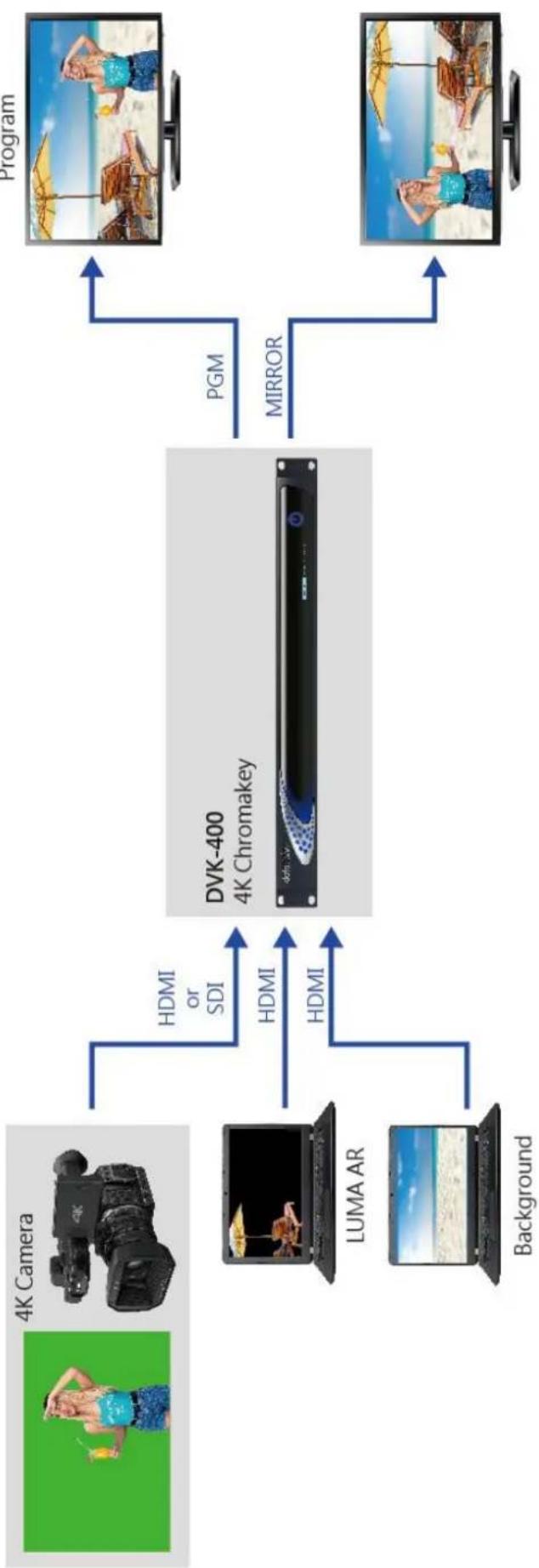
flowchart
graph LR
    A["4K Camera"] -->|HDMI or SDI| B["DVK-400 4K Chromakey"]
    C["LUMA AR"] -->|HDMI| B
    D["Background"] -->|HDMI| B
    B -->|PGM| E["Program"]
    B -->|MIRROR| F["Program"]
Chapter 2 Connections and Controls
Various control buttons and connection ports will be introduced in this chapter.
2.1 Front View

| Buttons | Descriptions | |
 | The power button can be found on the front panel. Before pressing the power button to turn on your DVK-400, make sure the power switch at the rear of the device has already been turned on. | |
2.2 Rear View

| Connections | Descriptions | |
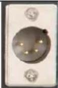 | DC INDC in socket connects the supplied 12V PSU. | |
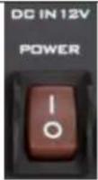 | DC IN 12V POWER SwitchMake sure this power switch is turned ON before pressing the power button on the front panel. | |
 | Grounding TerminalWhen connecting this unit to any other component, make sure that it is properly grounded by connecting this terminal to an appropriate point. When connecting, use the socket and be sure to use wire with a cross-sectional area of at least 1.0 mm^2 . | |
 | FOREGROUND CAMERAComnect a foreground camera to this HDMI port. | |
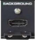 | BACKGROUNDConnect a background video source on which the chromakeyed foreground will be overlaid to this HDMI port. | |
 | AUXThe AUX port allows the user to connect a notebook PC for importing a logo.Note: This port supports HDMI 1.4 ONLY. | ||
 | B.B/EXT.SYNCThese two ports allow you to input or to loop out the synchronous signal. | ||
 | SDI IN/OUTFOREGROUND CAMERA INConnect a foreground camera to this SDI port.LOOP THRUThe Loop Thru port loops the FOREGROUND CAMERA IN video to an externally connected monitor. | ||
 | SDI/HDMI OUTConnect an external monitor for display of a combined view of the chromakeyed foreground and the background video.PGM is the program view and PVW is preview. | ||
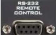 | RS-232 REMOTE CONTROLUse an RS-232 to USB adapter cable to connect your laptop to the device directly for remote control. | ||
 | DVIPThe DVIP port allows the user to control DVK-400 on a laptop or PC computer from a remote location. Use any Ethernet cables to connect directly to the device or via a router.IP Address Reset HoleTo the right of the DVIP port, there is an IP address reset hole. To reset the device's IP address to its factory default (192.168.100.120), use a thin needle to push the button then hold for at least 5 seconds until the reset starts. Use the default IP address to connect afterwards. | ||
 | F/W UPGRADEConnect a USB thumb drive containing the latest firmware file to this USB port for firmware upgrade. |
Chapter 3 Basic Setup
Basic setup of the device is illustrated in the diagram below.

The DVIP and RS-232 ports allow the user to control DVK-400 on a laptop or PC computer from a remote location. Before establishing connection, the user should first download the User Interface Software from Datavideo's official website (www.datavideo.com). Unzip the downloaded file, then in the unzipped folder, locate
the UI icon shown on the left.
Double click the icon to open the UI then follow the steps outlined in the subsequent sections to establish direct connection to your DVK-400.
3.1 DVIP Connection
DVIP is a network control protocol developed by Datavideo to facilitate connection to our devices. Follow the steps outlined below to establish direct connection to your DVK-400 from a laptop or PC via DVIP.
- Use any Ethernet cables to connect a laptop or PC directly to the device's DVIP port.
- The default static IP address is 192.168.100.120 so set your PC's IP address to 192.168.100.XXX as shown below.

- Open the DVK-400 User Interface then at the top right corner of the interface, click the "Globe" icon.

- On the "CONNECT" window that opens, you will be able to view the device's network settings.
![CONNECT Interface DVIP EtherNetCard [192.168.100.5] Ethernet Scan IP Select 192.168.100.120 Host Name DVK-400 Mac Address 00:07:36:04:06:00 Address Mode Static IP IP Address 192.168.100.120 Network Mask 255.255.255.0 Gateway 192.168.100.1 Primary DNS 8.8.8.8 Secondary DNS 8.8.4.4 Connect DisConnect Reset Save](/content/2026/05/830672/images/0644009579d09fd32107e35a87fe91bac3d543ea57189b4f596c4d59605b7760.jpg)
- Select DVIP from the "Interface" drop-down menu.

- Select your laptop's Ethernet card from the "EtherNetCard" drop-down menu, which is 192.168.100.5 in this example. If this is your first time using the device, click the "Scan" button on the right of the "EtherNetCard" drop-down menu to search for the device on the network. While searching, you should see the message "Scanning" at the bottom left corner of the "CONNECT" window.
![EtherNetCard [192.168.100.5] Ethernet IP Select [192.168.100.5] Ethernet [192.168.1.72] Wi-Fi](/content/2026/05/830672/images/d388ce45a8057396df4178f1ab83b9f8426723e49271b19a2402c7ac6a8d8fac.jpg)
- From the "IP Select" drop-down menu, select the IP address of the DVK-400 that you would like to connect. Once selected, the Host Name (DVK-400), Mac Address, Address Mode, IP Address and other network settings will be shown.

- Click the "Connect" button to start connecting to the device. As soon as the connection to the device has been established successfully, you will see the message "Connected" shown in yellow, after which the "Connect" window will shut down automatically.
![CONNECT Interface DVIP EtherNetCard [192.168.100.5] Ethernet Scan IP Select 192.168.100.120 Host Name DVK-400 Mac Address 00:07:36:04:06:00 Address Mode Static IP IP Address 192.168.100.120 Network Mask 255.255.255.0 Gateway 192.168.100.1 Primary DNS 8.8.8.8 Secondary DNS 8.8.4.4 Connect DisConnect Connected Save](/content/2026/05/830672/images/60de6cab23453e3be3d7905984d8c4cb868e578232504e32578813fbdfa8770f.jpg)
Note: After you've modified the network settings such as switching to DHCP mode, please restart the UI for the new settings to take effect. Remember to click the "Save" button after change.
3.2 RS-232 Interface
In addition to DVIP, you can also connect to the DVK-400 via RS-232. Follow the steps outlined below to establish direct connection to the device from a laptop or PC via RS-232.
- Use an RS-232 to USB adapter cable to directly connect your laptop to the DVK-400.
- Open the DVK-400 User Interface then at the top right corner of the interface, click the "Globe" icon.

- On the "CONNECT" window that opens, select RS-232.

-
From the "Comport" drop-down menu, select the device's corresponding COM port which is COM7 in this example
-
Click the "Connect" button to establish connection.
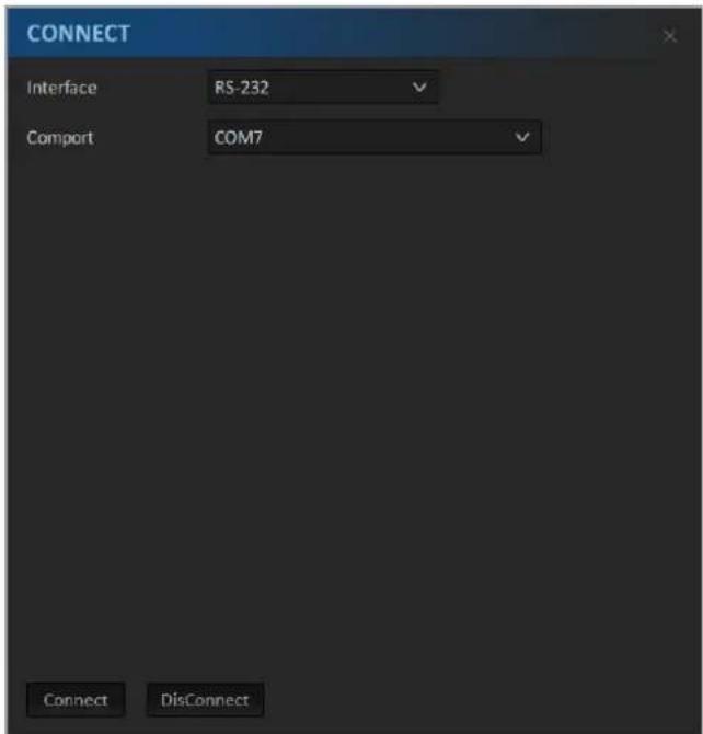
Note: In case of connection failure, check that the cable is properly connected and the laptop's COM port is not occupied by other software.
Chapter 4 User Interface
In this chapter, various functions of the user interface will be described.
Note: You can also use TPC-700 Touch Panel Controller to control DVK-400. See the TPC-700 user manual for setup instructions.
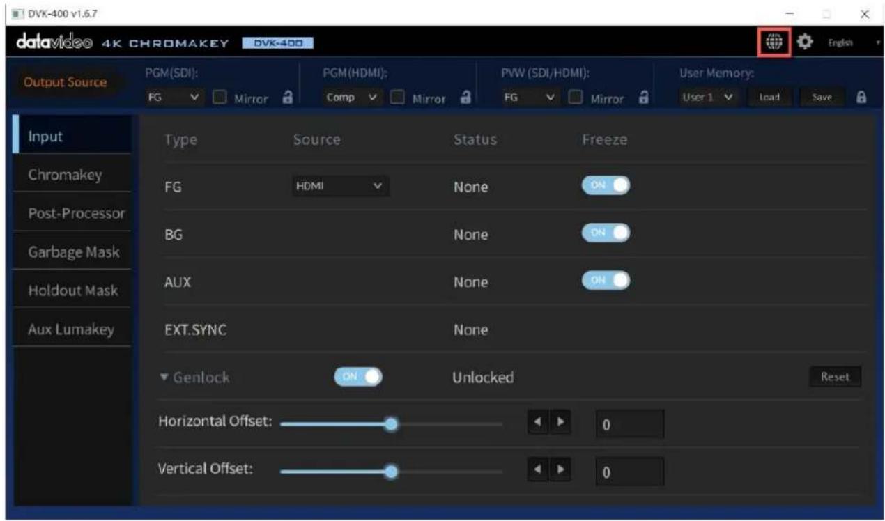
4.1 Output Source
The Output Source row located at the very top of the UI allows you to configure the video source for your output ports.

PGM (SDI)
The PGM (SDI) drop-down menu allows you to select one of the following video sources for the PGM SDI OUT port.

FG: FOREGROUND CAMERA video source.
BG: BACKGROUND video source.
AUX: Video source connected to the AUX port.
Matte: The Foreground's Luma MATTE (Black = Transparent, White = Solid, Gray = translucent)
PFG: Processed Foreground, i.e. the background color of the
foreground image will be gray or color reproduced.
Comp: A combined view of FOREGROUND and BACKGROUND.
Notes
- Checking the Mirror checkbox flips the output image along the vertical axis.
- Click the lock icon locks the output port, thus disabling video source selection.
PGM (HDMI)
The PGM (HDMI) drop-down menu allows you to select one of the following video sources for the PGM HDMI OUT port.
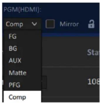
FG: FOREGROUND CAMERA video source.
BG: BACKGROUND video source.
AUX: Video source connected to the AUX port.
Matte: The Foreground's Luma MATTE (Black = Transparent, White = Solid, Gray = translucent)
PFG: Processed Foreground, i.e. the background color of the foreground image will be gray or color reproduced.
Comp: A combined view of FOREGROUND and BACKGROUND.
Notes
- Checking the Mirror checkbox flips the output image along the vertical axis.
- Click the lock icon locks the output port, thus disabling video source selection.
PVW (SDI/HDMI)
The PVW (SDI/HDMI) drop-down menu allows you to select one of the following video sources for the PVW SDI and HDMI OUT port.

FG: FOREGROUND CAMERA video source.
BG: BACKGROUND video source.
AUX: Video source connected to the AUX port.
Matte: The Foreground's Luma MATTE (Black = Transparent, White = Solid, Gray = translucent)
PFG: Processed Foreground, i.e. the background color of the foreground image will be gray or color reproduced.
Comp: A combined view of FOREGROUND and BACKGROUND.
Notes
- Checking the Mirror checkbox flips the output image along the vertical axis.
- Click the lock icon locks the output port, thus disabling video source selection.
User Memory

The User Memory function allows the user to store the current UI settings and recall previously saved settings.
To save the UI settings, select a user preset then click the "Save" button.
To recall previously saved settings, select a user preset then click the "Load" button.
Note: When the Save or Load is complete, you will be prompted the message "Setting Completed".
4.2 Input
Input page shows the input information.

Type: A list of available input interfaces on the DVK-400.
- FG: Foreground
- BG: Background
- AUX: AUX port
- EXT SYNC: It allows you to connect an external synchronous signal which acts as the source of the reference signal. It accepts various synchronous signals such as the Tri-level sync or NTSC/PAL black burst signal.
Source: After successfully connecting to the DVK-400 via DVIP or RS-232 port, a drop-down menu will appear, displaying the interface (SDI/HDMI) to which the foreground camera is connected.
Status: Resolutions of the foreground camera or background video will be shown. The Genlock will be shown as Locked or Unlocked.
Freeze: The “Freeze” function allows you to freeze the input videos connected to the foreground camera, background camera, and AUX ports. Slide the “Freeze” slider right to freeze the input video of its corresponding source port. Once the video is frozen, you can remove the physical input source connection while keeping the frozen image on the output screen.
Note: The DVK-400 does not save a copy of the frozen image on the device so the frozen image will be lost as soon as the DVK-400 is turned off.
Genlock
When the output frame rate is the same as or exactly twice the frame rate of the EXT. SYNC, the Genlock can be locked. The Genlock function also offers "Horizontal Offset" and "Vertical Offset" which are shown in the diagram below.
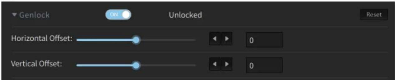
• The Horizontal Offset range is ±5500 Pixels
• The Vertical Offset range is ±500 Lines
When the Genlock is locked, you will see its status field showing "Locked".
Note: The Genlock will only be locked if the Genlock slider shows "ON" and the output resolution is the same as or exactly twice the frame rate of the EXT. SYNC, or else, you will see the status showing "Unlocked".
For example, given that the input signal of the EXT. SYNC is PAL (frame rate is 25), the Genlock can be locked if the output resolution is 2160p50 or 2160p25. The Genlock cannot be locked if the output resolution is 2160p60, 2160p30 or 2160p24.
4.3 Chromakey

In this section, we will show you how you can adjust the chromakey settings which involve the following:
- Matte Generation
-
Dark Enhancement
-
Bright Enhancement
• Shadow Enhancement - Spill Suppression
- Edge Fix (HD only)
Matte Generation
To continue, the Matte Generation option at the top of the page needs to be enabled first. To reset Matte settings to default values, simply click the "Reset" button.

Note: If this option is disabled, Chomakey will be turned off and the AUX Lumakey will be overlaid on the background instead, which can be displayed on the output monitor by selecting COMP as the output.
Backing Color
In "Backing Color", you can select the foreground's screen color manually or enable the auto mode to allow automatic screen color selection. In most cases, auto mode will be adequate.


Click the "Auto" button to enable automatic screen color selection. Once clicked, the foreground will be shown on PVW OUT along with a crosshair (+) scanning across the entire monitor to collect the screen color data. The DVK-400 then calculates the optimal screen color, adjusts the chromakey parameters accordingly and finally applies the key to the foreground. This entire process should take approximately 2 seconds.
Note: If saturation or brightness of the green/blue screen is lower than 20%, the "Auto" mode may fail. To fix this problem, please improve the studio's lighting and adjust the camera settings.

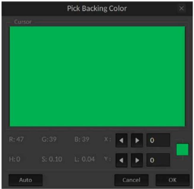
Click the dropper icon to manually select the screen color. When clicked, the "Pick Back Color" window will appear on the notebook/PC and the foreground will be shown on
PVW OUT along with a crosshair (+). Use the mouse to move the crosshair to the desired screen color then click the mouse and the "Pick Back Color" window should display the selected color.
Once you've selected the desired screen color, you can either click "Auto" or "OK" on the "Pick
Back Color" window to confirm the selected color and allow the DVK-400 to adjust the chromakey parameters accordingly then apply the key to the foreground image.
Open Angle
The “Open Angle” allows you to set the chromakey color range. In most cases, ±77 will be appropriate. For example, when yellow/green objects become translucent, decrease the chromakey color range until they become opaque. You can use the slider or left and right arrow keys to adjust the “Open Angle”.

Black Level
Increase the black level to eliminate uneven distribution in the background of the composite output. Switch PVW OUT to Matte (see Section 4.1 Output Source) for a clearer view of the process. You can use the slider or left and right arrow keys to adjust the "Black Level".

White Level
Adjust the white level to obtain a uniform distribution of white on objects which should remain fully non-transparent. Uneven distribution may arise from the fact that the foreground subject may have color components close to the screen color. In this case an adjustment can be made using the function known as White Level.
Switch PVW OUT to Matte for a clearer view of the process. You can use the slider or left and right arrow keys to adjust the "White Level".

Dark Enhancement
Turning ON this option enables Dark Enhancement.

Dark Level
The Dark level is 200 by default. If it is increased, the black object or hair will become more apparent. You can use the slider or left and right arrow keys to adjust the "Dark Level". Click "Reset" to return to the default value.
Bright Enhancement
Turning ON this option enables Bright Enhancement.

Bright Level
The Bright level is 200 by default. If it is increased, the transparent object, glass or smoke will become more apparent. You can use the slider or left and right arrow keys to adjust the "Bright Level". Click "Reset" to return to the default value.
Shadow Enhancement
Turning ON this option enables Shadow Enhancement.

Shadow Enhancement
Under certain circumstances, shadow enhancement is used to show shadows on the ground or enhance very fine black hair. You can use the slider or left and right arrow keys to adjust the "Shadow".
Note: Disable it if you do not need to use this feature.
Spill Suppression
When you key an image that was shot against a blue screen or green screen, some color will have reflected from the screen to illuminate the edges, or even the interior, of the foreground subject. This unwanted coloration of the subject is called spill. Spill suppression helps you eliminate the spill.

Default
Depending on the amount of the spill, click Spill Low, Spill Mid or Spill High to select one spill suppression mode, thereby allowing the DVK-400 to automatically remove the spill.

Spill Suppression
Spill suppression removes the green or blue color reflected onto the foreground subject from the screen. Setting the spill suppression to zero removes the green or blue color component and setting the spill suppression to 500 adds the green or blue color component. A good spill suppression range is 400 – 700. The default value is 500. You can use the slider or left and right arrow keys to adjust the Spill Suppression.

Spill Balance
If the Spill Balance value is increased, the skin tone will be biased towards warm colors. If the Spill Balance value is decreased, the skin tone will be biased towards cool colors. A good Spill Balance value is 500. You can use the slider or left and right arrow keys to adjust the Spill Balance.

Edge Brightness
Adjust the edge brightness until the edge of the foreground subject is close to the screen color. Setting a low edge brightness value darkens the subject edge. You can use the slider or left and right arrow keys to adjust the Edge Brightness.

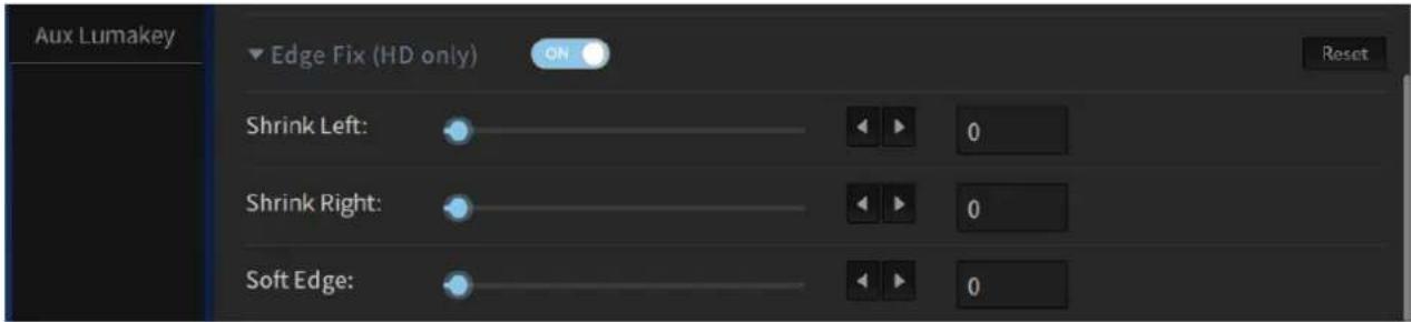
Edge Fix (HD)
The Edge Fix (HD) function allows you to adjust the left and right edges of the chromakeyed foreground object using the “Shrink Left” and “Shrink Right” functions respectively. The “Soft Edge” function softens edges of the chromakeyed foreground object.
Shrink Left
The range of the “Shrink Left” is from 0 to 50, which is approximately equivalent to 0 – 5.0 pixels of horizontal shrinking (step size: 0.1 pixel). You can use the slider or left and right arrow keys to adjust the Shrink Left.
Shrink Right
The range of the “Shrink Right” is from 0 to 50, which is approximately equivalent to 0 – 5.0 pixels of horizontal shrinking (step size: 0.1 pixel). You can use the slider or left and right arrow keys to adjust the Shrink Right.
Soft Edge
The range of the “Soft Edge” is from 0 to 100, which is approximately equivalent to applying 0 – 7 pixels of soft edge effect to both left and right edges simultaneously. You can use the slider or left and right arrow keys to adjust the Soft Edge.
4.4 Post Processor

FG PostAmp
Enable FG PostAmp to adjust Hue, Saturation, Contrast and Brightness for the foreground subject.
Use the slider or left and right arrow keys to change the respective values. To reset, simply click the Reset button.
FG Corrector
Enable FG Corrector to perform RGB color calibration for the foreground subject.
Use the slider or left and right arrow keys to adjust the RGB levels. To reset, simply click the Reset button.
BG Blur
Enable BG Blur to create a fuzzy background for BG and PFG video sources. Use the slider or left and right arrow keys to adjust the blur level. 0 means no blur and 100 is maximum blur.
Blur time sets the fuzzification time, ranging from 0 to 20. For example, if the blur time is set to 20, multiply this number by 0.1 to derive the fuzzification time of 2 seconds. Hence, as you switch the BG Blur ON/OFF, you will see the background transitioning to the fuzzy or original background within the set blur time.
To reset, simply click the Reset button. The default blur value is 50 and the default blur time is 5.
4.5 Garbage Mask
After you apply a key, you may need to crop unwanted background elements that cannot be keyed, such as the screen edge or lighting rigs that appear in the background. Using the Garbage Mask tool, you can create a garbage mask that removes unwanted elements.

First enable the Garbage Mask (ON by default), then set the border width by adjusting the mask's left, right, top and bottom edges using the respective sliders or the left and right arrow keys. Increasing these values reduces the size of the foreground screen.
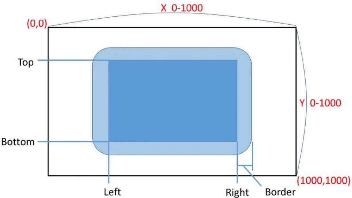
"Border" allows you to "soften" the mask edges. Increasing the border value creates round soft gradient edges as shown below.

flowchart
graph LR
    A[" "] --> B[" "]
The Border value ranges from 0 to 100. Use the slider or left and right arrow keys to change the value.
Invert, when turned ON, reverses the default garbage mask (swapping its opaque and transparent areas). This means that by enabling Invert, the transparent area is the border and the central area is blocked.
4.6 Holdout Mask
The holdout mask allows you to define the area of the image that would remain unkeyed, for example a green area on the TV screen.

First enable the Holdout Mask (OFF by default), then set the area where it is blocked from chromakey by adjusting its left, right, top and bottom edges using the respective sliders or the left and right arrow keys.
"Border" allows you to "soften" the mask edges. Increasing the border value creates round soft gradient edges as shown below.

natural_image
Two blue rectangular shapes with a rightward arrow, no text or symbols presentThe Border value ranges from 0 to 100. Use the slider or left and right arrow keys to change the value.
Invert, when turned ON, reverses the default holdout mask (swapping its opaque and transparent areas). This means that by enabling Invert, the central area is transparent and the border is blocked.
4.7 AUX Lumakey
The “AUX Lumakey” performs lumakey on the input source from the AUX interface. Various parameters of the AUX lumakey will be described in this section.

First enable the AUX Lumakey then adjust the following parameters. To reset the parameters, simply click the Reset button.
Key Mode
Select "Black" if the foreground is shot against a black background and "White" if the foreground is shot against a white background.
Cut Off
The default “Cut Off” value is 0. Increase this value gradually until either of the black and white backgrounds of the AUX source is 100% removed. For a black background, set Cut Off to 10-20% of its maximum value. For a white background, set Cut Off to 80-90% of its maximum value.
Softness
It allows users to determine the softness of the edge of the foreground subject. Increase this value if you would like a gradient edge effect for the foreground subject. Please note that setting softness to a high value may cause the foreground subject to become semi-transparent.
Opacity
Opacity sets the transparency of the foreground subject. Setting it to 1000 will make the foreground subject transparent and a zero value means fully opaque.
Layer Swap
Enable "Layer Swap" to place the chromakey layer on top of the AUX Lumakey layer and vice versa.
Swap Time
Swap time sets the transition time during layer swap. For example, if the swap time is set to 20, multiply this number by 0.1 to derive the transition time of 2 seconds.
4.8 Setup
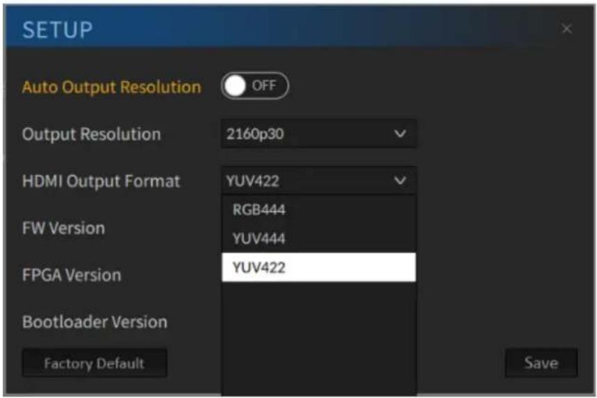
Click the gear icon at the top right corner of the interface to open the Setup window as shown below.
Auto Output Resolution
Auto Output Resolution, when enabled, allows the output resolution to automatically follow the foreground resolution. The Auto Output Resolution is OFF by default.
Note: You will not be able to manually set the output resolution when auto output resolution is enabled. Clicking the "Factory Default" button does not reset the auto output resolution option.

Output Resolution
Use the Output Resolution drop-down menu to manually set the output resolution.
Note: You will not be able to manually set the output resolution when auto output resolution is enabled. You will be prompted that the output resolution follows the foreground resolution and cannot be changed manually.

HDMI Output Format
Select the HDMI output format from this drop-down menu. The available options are RGB444, YUV444 and YUV442.
FW Version
Firmware version is shown in this field.
FPGA Version
FPGA Version is shown in this field.
Bootloader Version
Bootloader version is shown in this field.
Note: Click the "Save" button to save new changes.
Reset to Factory Defaults
Follow the steps below to reset the DVK-400 to Factory Default Settings.
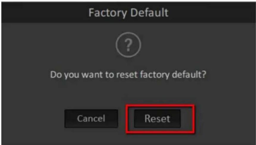
- Click the "Factory Default" button.

- Click the "Reset" button to reset the DVK-400 to Factory Default Settings.
Chapter 5 Advanced Applications
In this chapter, we will show you various examples of video chromakeying, garbage and holdout masks and AUX lumakey.
5.1 Video Chromakeying
First set up your device according to hardware setup instructions described in Chapter 3. Then follow the steps outlined below to perform video chromakeying.
1. Open DVK-400 User Interface.

2. Open the "Chromakey" page.

- Connect your foreground camera to DVK-400.

natural_image
Mannequin head with curly brown hair against a green background, with Coca-Cola bottles and cans on a white table (no text or symbols visible)- In "Backing Color" on Chromakey page of the UI, you either click "Auto" to generate the key automatically or the dropper icon to manually select the key color. See Section 4.3 Chromakey for more information about key generation.
- After the foreground is chromakeyed, switch your output to the MATTE view shown below.

natural_image
Silhouette of a person with curly hair against a black background (no text or symbols)-
Fine tune the parameters (black level, white level, dark level, bright level, shadow, spill suppression and edge brightness) to achieve an optimal key. See Section 4.3 Chromakey for more information about these parameters.
-
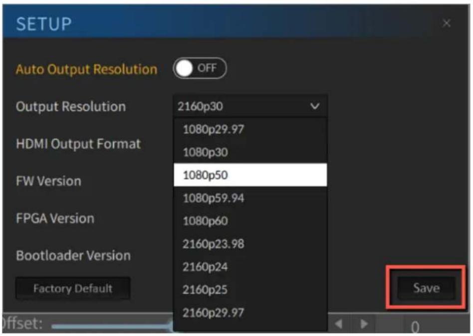
Open the Setup window by clicking the gear icon at the top right corner of the UI then set the output resolution to the resolution of the foreground camera. Click the Save button after that.
- Run the background video.
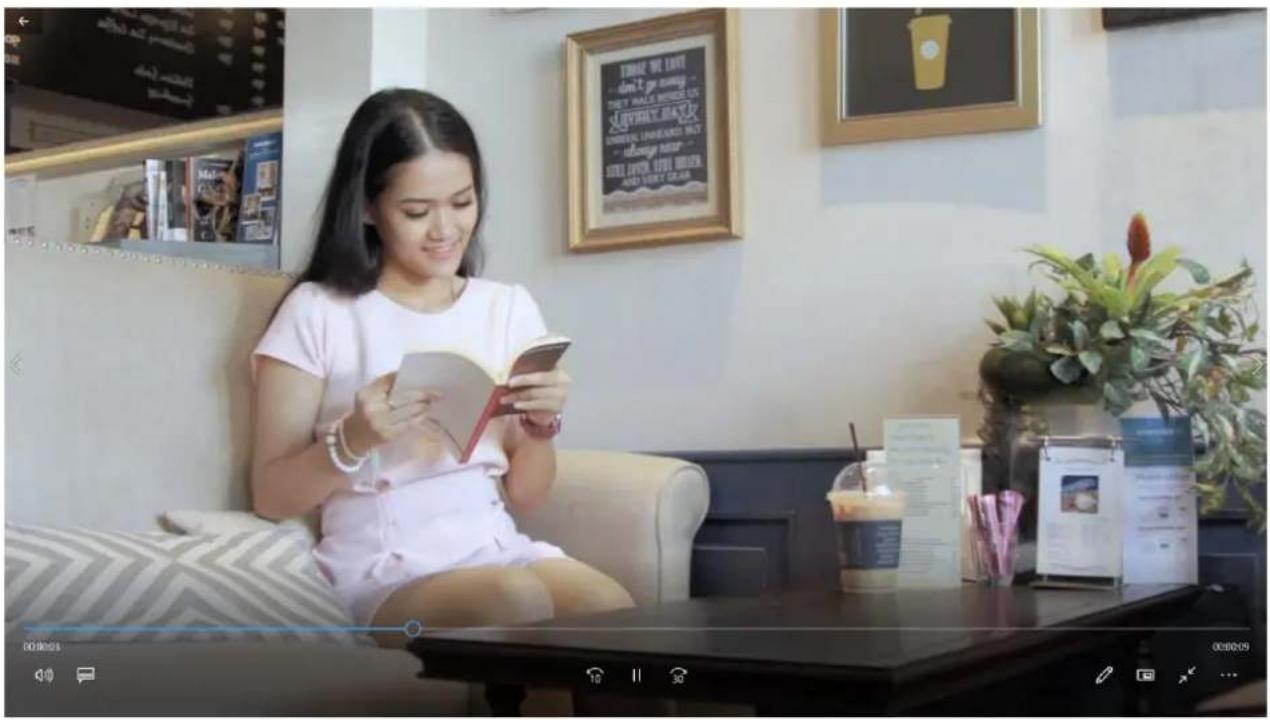
- Set one of your outputs to "COMP" to show a combined view of the chromakeyed foreground and the background video as shown in the diagram below.

natural_image
Two women sitting on a sofa reading a book, with mannequins and beverage cans in the foreground (no visible text or symbols)5.2 Crop using Garbage Mask
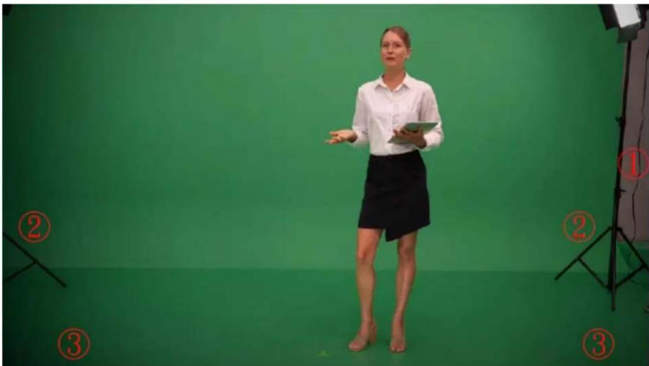
After you apply a key, you may need to crop unwanted background elements that cannot be keyed, such as (1) the screen edge, (2) lighting stands that appear in the background and (3) uneven distribution of light. Using the Garbage Mask tool, you can create a garbage mask that removes unwanted elements. See Section 4.5 for instructions.
natural_image
Woman in business attire standing in front of a green studio with numbered callouts (no text or symbols on the main subject)Open the composite view on one of the output monitors and you should be able to see a combined view of the talent and the background as shown in the diagram below. Then activate
the garbage mask, and adjust the mask until the unwanted elements are completely removed. The yellow rectangle specifies the mask edges and is drawn for illustration purpose.

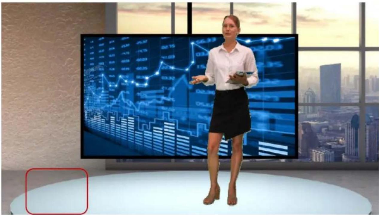
In the red rectangle at the bottom left corner of the diagram below, because of uneven distribution of light, the mask edge is vaguely seen.

To remove mask edges entirely from the composite view, increase the "Border" value to soften the edges. As shown in the diagram below, mask edges disappear and the image areas around them are smoothened.
5.3 Restore Foreground with a Holdout Mask
The holdout mask allows you to define the area of the image that would remain unkeyed, for example a green area on the TV screen. In this section, we will show you how you can cover the green area of the image that should be kept.
To understand how the holdout mask works, you need to first understand the layer order on the DVK-400 shown in the diagram below. The holdout mask sits between the AUX Lumakey layer and the foreground image, therefore, by enabling the holdout mask, you are preventing the masked area of the foreground image from being chromakeyed thus preserving the image layers overall.

Now, follow the steps outlined below to restore the foreground with a holdout mask.
- The diagram below is a foreground camera view consisting of a teacher presenting the slides using a TV.

- As shown in the diagram below, the green components in the pictures and the title of the slide shown against a green rectangle at the bottom left corner of the TV are incorrectly removed after chromakey is applied. If left uncorrected, the background image will show through the TV in these areas.

- In these cases, you can mask the part of the subject that is incorrectly keyed with a holdout mask to restore the original image. On the UI, open the Holdout Mask page, and adjust the mask edges to cover the TV area.
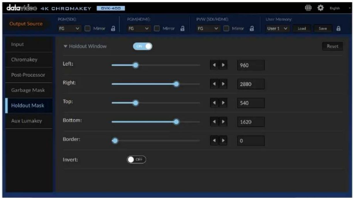
- In the following image, green components of the TV are kept after chromakey is applied.

5.4 More Applications of Garbage and Holdout Masks
In this section, we will show you more examples of using garbage and holdout masks in a chromakey.
Example 1
Please note that in this example, the Invert option should be turned OFF for both Garbage and Holdout masks.
As shown in the following diagram, there are issues in the foreground image such as (1) the screen edges, (2) a lighting stand and (3) green components in the TV image.

natural_image
Studio scene with a man in a suit standing beside a large screen showing a soccer match, under a green backdrop (no visible text or symbols)To solve these issues, we will need a garbage mask to remove the screen edges and the light stand and cover the TV with a holdout mask to ensure that the TV area is not keyed. As shown in the diagram below, rectangle 1 is the transparent area defined by the garbage mask and rectangle 2 is the holdout mask covering the TV. See Sections 5.2 and 5.3 for instructions on how you can activate the two masks on the foreground.

After you've defined the garbage and holdout masks, you will see the chromakeyed foreground overlapped on the background with the desired effects shown in the diagram below.

natural_image
Studio scene with a man in a suit standing beside a large screen displaying a soccer match, city skyline in background (no visible text or symbols)Example 2
There are times when we want to remove the area inside the garbage mask and keep the area outside the holdout mask from being keyed. In these cases, the Invert option must be enabled to reverse the order for both masks.
In the foreground shown below, the ceiling lamp (1) can be removed by a reversed garbage mask and the green screen (2) can be chromakeyed with a reversed holdout mask. After a chromakey is applied to the foreground, the background should show through the green screen only.

First enable garbage and holdout masks and turn ON Invert for both masks. Then adjust edges of the two masks accordingly. As shown in the diagram below, the garbage mask is depicted by rectangle 1 and the holdout mask is depicted by rectangle 2. See Sections 5.1 and 5.2 for instructions on how you can activate the two masks on the foreground.
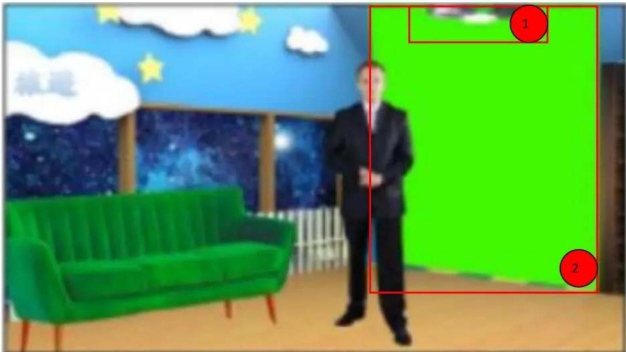
The background image is shown below.

natural_image
Panoramic cityscape featuring the Taipei Tower under a clear blue sky, with dense urban buildings and green hills in the foreground (no visible text or signage)Apply the chromakey to the foreground image then set the output source to COMP on one of the output monitors, you should see a combined view of the chromakeyed foreground and the background image as shown below.

natural_image
Interior scene with a man in a suit standing beside a green sofa, a cityscape mural featuring the Taipei Tower and starry sky (no text or symbols visible)5.5 Animate your Program
The DVK-400 has a layer swap function that can be found on the AUX Lumakey page of the UI. This function swaps the Chromakey and AUX Lumakey Layers with a fade transition. Please note that the fade transition time can be predetermined by setting the Swap Time.
Example 1
The diagram below illustrates a teaching scene. The Earth is the AUX Lumakey layer and the teacher is the chromakeyed foreground. With the Layer Swap disabled, the AUX Lumakey layer is above the Chromakey layer, therefore it looks as if the teacher's hand moves behind the 3D Earth.

natural_image
Woman presenting in front of a large globe displayed on a wall, with bookshelves and a blue world map in the background (no visible text or symbols)After the teacher moves the hand away from the simulated 3D Earth, turn ON the Layer Swap to move the Chromakey layer on top of the AUX Lumakey.

natural_image
Woman standing in front of a large globe displayed on a wall with bookshelves and a world map background (no text or symbols visible)When the teacher walks to the Earth, it would look as if the teacher walks to the front of the Earth.

natural_image
Woman standing in front of a world map display with bookshelves and a large globe (no text or symbols visible)Example 2
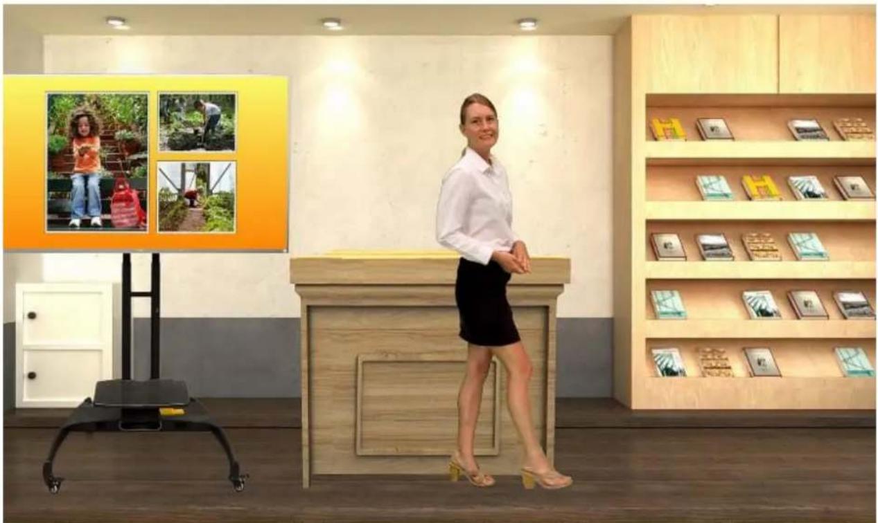
The diagram below illustrates a second teaching scene. The lectern is the AUX Lumakey layer and the teacher is the chromakeyed foreground. With the Layer Swap enabled, the Chromakey layer is above the AUX Lumakey layer, therefore it looks as if the teacher is moving in front of the lectern.
natural_image
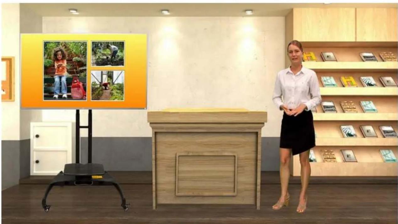
Interior of a modern retail store with a woman standing beside a reception desk, shelves displaying photos and text, and a small cart nearby (no visible signage or text)Turn OFF the Layer Swap as soon as the teacher moves to either sides of the lectern.
natural_image
Interior of a modern retail store with a woman standing beside a display table, framed photos on shelves and a large wooden counter (no visible text or signage)Now, when the teacher walks to the lectern, it would then seem as if she walks to the back of the lectern as shown in the diagram below.

natural_image
Interior scene of a modern retail store with a customer at a counter, shelves displaying photo frames, and a display panel with a woman in the background (no visible text or symbols on main objects)Chapter 6 Appendices
Appendix 1 Firmware Update
Datavideo usually releases new firmware containing new features or reported bug fixes from time to time. Customers can either download the firmware as they wish or contact their local dealer or reseller for assistance.
This section outlines the firmware upgrade process which should take approximately few minutes to complete.
The existing settings should persist through the firmware upgrade process, which should not be interrupted once started as this could result in a non-responsive unit.
Requirements
- Latest firmware file
- A USB thumb drive
- A monitor for viewing the upgrade progress
Update Procedure
- Download the latest DVK-400 firmware from the Datavideo official website (www.datavideo.com)
- Unzip the downloaded firmware files (DVK400FW.bin/DVK400FP.bin) to the root directory of a USB thumb drive.
Note: Make sure the USB thumb drive is formatted to FAT16 or FAT32.
- Connect an SDI or HDMI monitor to the DVK-400 for viewing the upgrade progress.
- Insert the thumb drive with the latest firmware files to the USB FW Upgrade port located at the rear of the device then turn ON the power of the DVK-400 to start the firmware upgrade automatically.

Note: Nothing will be shown on the monitor while the firmware is being updated.
- Upon seeing the monitor displaying 1080p59.94 color bars shown below, the firmware update is complete and you may remove the USB thumb drive from DVK-400.

natural_image
Color test pattern with vertical bars in various hues including gray, cyan, yellow, green, magenta, red, blue, and black (no text or symbols)- On the UI, open the Setup window (see Section 4.8) check versions of the firmware files installed.
Appendix 2 Frequently-Asked Questions
This section describes problems that you may encounter while using the DVK-400. If you have any questions, please refer to related sections and follow the suggested solutions. If the problem still exists, please contact your distributor or the service center.
| NO. | Problems | Solutions |
| 1 | How to reset to the device's default IP address? | See IP address reset hole description inSection2.2 Rear View. |
| 2 | On the UI's input page, theForeground's status shows "None". | Make sure that you have properly connected and turned on the foreground camera. |
| 3 | The monitor not displaying theforeground and the crosshair after clicking the dropper icon [IMAGE] | Make sure the monitor is connected to SDI or HDMI PVW OUT. |
| 4 | What are the 3G-SDI standards supported on the DVK-400? | Level A, Level B-DL and Level B-DS are supported on the DVK-400. |
| 5 | Why is BG status on the Input page of the UI always showing 2160p29 even though the MAC/PC connected to the BACKGROUND port has a resolution set differently, which is 1080p in this case?This is because the computer will output with the resolution matching the maximum resolution supported by the graphics card or the connected device, which is 2160p29 in this case. The purpose is to provide the best visual effect. Solutions to this issue are provided as follows:If you are using a MAC computer, download theDisplay Menuapp from http://displaymenu.milchimgemuesefach.de/index.htmlto manually set the output resolution to 1080p.If you are using a PC, follow the steps below to force the output resolution to 1920x1080.1. ClickStart Menu → Settings, then on theSettings windowthat opens, selectSystem, thenDisplay. Set the display resolution to 1920 x 1080 then click “Advanced display settings” right below. | |
- On the “Advanced display settings” window, select “Display 2: DVK-400” and you should see that the active signal resolution being 3840 x 2160 with a refresh rate of 29 Hz. To modify the resolution, click “Display adapter properties for Display 2”.

- On the Display Adapter Properties window that opens, click "List All Modes".

- Select "1920 by 1080, True Color (32 bit), 59 Hertz" then click OK.

- On the Display Adapter Properties window, click "Apply".
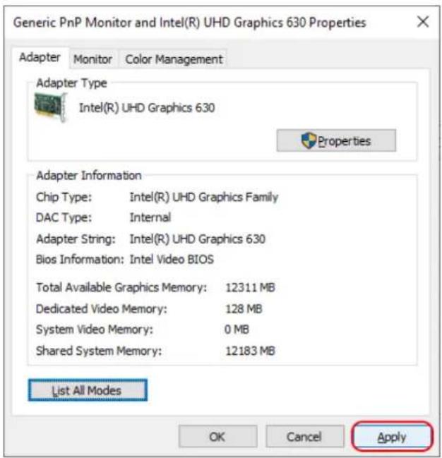
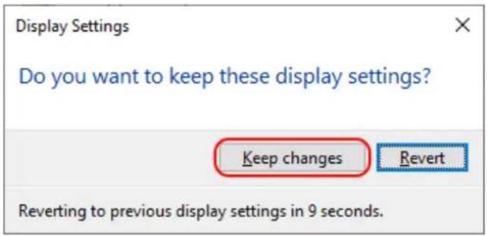
- Click "Keep Changes" to save the change.
- You should now see the "Active signal resolution" and the "Refresh rate (Hz)" changed to 1920 x 1080 and 59 Hz respectively and DVK-400's BG Input Status showing the expected "1080p59".

6
In the diagram below, white smokes in the chromakeyed foreground show black edges on the rims.

To solve this issue, set the background brightness to a value lower than the foreground brightness, yielding a more natural look of the smoke as shown below.

7.
What is the delay for the SDI IN/SDI OUT on the DVK-400?
DVK-400's SDI IN to SDI OUT delay is about 40ms, which will be determined by the frame rate and whether the Genlock function of the DVK-400 is enabled or not. If the frame rates of the SDI IN and SDI OUT are the same, there are two scenarios.
- If Genlock is enabled and the SDI IN is genlocked, then SDI OUT is fixed 1 frame delayed (about 16 to 40ms) to SDI IN, which can be +/-500 lines(within +/-20ms)
| fine-tuned by the Genlock offset control.2. If Genlock is disabled, and then the delay may vary over time, the delay will be within 40ms compared to the SDI IN. |
Appendix 3 Dimensions

Unit: mm
Appendix 4 Specifications
| Model | DVK-400 |
| Product Name | 4K Chromakey |
| Video Standard | 4K/3G/HD |
| Video Process | 4:4:4 10 bit |
| Video Format | 3840 x 2160p 60/59.94/50/30/29.97/251080p 60/59.94/50/30/29.97/251080i 60/59.94/50 |
| Foreground Inputs | 1 x 12G/6G/3G-SDI1 x HDMI 2.0 |
| Background Inputs | 1 x HDMI 2.0 |
| Loop Through | 1 x 12G/6G/3G-SDI Camera Loop Out |
| AUX Input | 1 x HDMI 1.4(Lumakey Overlay, External Matte or Camera) |
| Video Output | 1 x 12G/6G/3G-SDI1 x HDMI 2.0 |
| Video PVW Output | 1 x 12G/6G/3G-SDI1 x HDMI 2.0 |
| Color Space | SDI : YUV 4:2:2, 10-bit, limited rangeHDMI: RGB 4:4:4/YUV 4:4:4/YUV 4:2:2, 10-bit, full/limited range |
| Keying Options | Chromakey Green/Blue |
| Key Mask/Spill Correction | Yes |
| Color Processor | Yes |
| Noise Reduction | Yes |
| User Preset | 8 |
| Sync Reference | Input & Loop Output (Tri-Level Sync or Black Burst) |
| Controlled via | Ethernet/RS-232 |
| Chassis | 1RU 19” Rackmount Design |
| Dimensions (LxWxH) | 484 x 243 x 44 mm |
| Weight | 2.7 Kg |
| Operating Temperature | 0 – 40°C |
| Power | DC 12V/34.7W (12V/5A) |
Notes
Service & Support
It is our goal to make owning and using Datavideo products a satisfying experience. Our support staff is available to assist you to set up and operate your system. Contact your local office for specific support requests. Plus, please visit www.datavideo.com to access our FAQ section.
Please visit our website for latest manual update.
https://www.datavideo.com/product/DVK-400
datavideo
www.datavideo.com

@DatavideoUSA
@DatavideoEMEA
@DatavideoTaiwan
@DatavideoAsia
@DatavideoIndia2016
@Datavideojapan
@DatavideoLatam
@DatavideoBrasil

@Datavideo
@Datavideo EMEA
@Datavideo Taiwan

@DatavideoUSA
@DVTWDVCN

@DatavideoUSA
@DatavideoEurope
All the trademarks are the properties of their respective owners.

- DVK-400
- Instruction Manual
- Table of Contents
- TABLE OF CONTENTS......2
- FCC COMPLIANCE STATEMENT....4
- WARNINGS AND PRECAUTIONS ....4
- WARRANTY ....5
- DISPOSAL 6
- CHAPTER 1 PRODUCT OVERVIEW ....7
- CHAPTER 2 CONNECTIONS AND CONTROLS....9
- CHAPTER 3 BASIC SETUP ....11
- CHAPTER 4 USER INTERFACE ....17
- CHAPTER 5 ADVANCED APPLICATIONS....35
- SERVICE AND SUPPORT....60
- Disclaimer of Product & Services
- FCC Compliance Statement
- Warnings and Precautions
- Warranty
- Standard Warranty
- Three Year Warranty
- Disposal
- For EU Customers only - WEEE Marking
- Chapter 1 Product Overview
- Features
- Chapter 2 Connections and Controls
- Front View
- Rear View
- Chapter 3 Basic Setup
- DVIP Connection
- RS-232 Interface
- Chapter 4 User Interface
- Output Source
- PGM (SDI)
- Notes
- PGM (HDMI)
- PVW (SDI/HDMI)
- User Memory
- Input
- Genlock
- Chromakey
- Matte Generation
- Backing Color
- Open Angle
- Black Level
- White Level
- Dark Enhancement
- Dark Level
- Bright Enhancement
- Bright Level
- Shadow Enhancement
- Spill Suppression
- Default
- Spill Balance
- Edge Brightness
- Edge Fix (HD)
- Shrink Left
- Shrink Right
- Soft Edge
- Post Processor
- FG PostAmp
- FG Corrector
- BG Blur
- Garbage Mask
- Holdout Mask
- AUX Lumakey
- Key Mode
- Cut Off
- Softness
- Opacity
- Layer Swap
- Swap Time
- Setup
- Auto Output Resolution
- Output Resolution
- HDMI Output Format
- FW Version
- FPGA Version
- Bootloader Version
- Reset to Factory Defaults
- Chapter 5 Advanced Applications
- Video Chromakeying
- Open DVK-400 User Interface.
- Open the "Chromakey" page.
- Crop using Garbage Mask
- Restore Foreground with a Holdout Mask
- More Applications of Garbage and Holdout Masks
- Example 1
- Example 2
- Animate your Program
- Chapter 6 Appendices
- Appendix 1 Firmware Update
- Requirements
- Update Procedure
- Appendix 2 Frequently-Asked Questions
- Service & Support
- datavideo
Brand : DataVideo
Model : DVK-400
Category : Audiovisual Equipment