
RA21S - Access Point Edimax - Free user manual and instructions
Find the device manual for free RA21S Edimax in PDF.


| Product Type | Wireless Access Point |
| Brand | Edimax |
| Model | RA21S |
| Wireless Standards | IEEE 802.11ac/n/g/b |
| Frequency Band | 2.4 GHz / 5 GHz |
| Maximum Data Rate | 1200 Mbps (2.4GHz: 300 Mbps, 5GHz: 867 Mbps) |
| Ethernet Ports | 1 x 10/100/1000 Mbps Gigabit LAN |
| Dimensions (W x D x H) | 150 x 100 x 30 mm |
| Weight | 200 g |
| Power Supply | 5V DC, 1A via Micro USB or PoE (802.3af) |
| Power Consumption | 5W max |
| Antenna Type | Internal, dual-band |
| Operation Modes | Access Point, Range Extender, WDS Bridge |
| Security | WPA/WPA2-PSK, WPA/WPA2-Enterprise, WEP, MAC Filter |
| Management | Web-based GUI, Edimax Pro App, SNMP, QoS |
| Mounting | Ceiling/Wall mount (bracket included) |
| Operating Temperature | 0°C to 40°C |
| Humidity | 10% to 90% non-condensing |
| Certifications | CE, FCC |
| Maintenance | Clean with a soft, dry cloth; keep vents unobstructed |
| Spare Parts & Repairability | No user-replaceable parts; contact support for repairs |
Frequently Asked Questions - RA21S Edimax
User questions about RA21S Edimax
0 question about this device. Answer the ones you know or ask your own.
Ask a new question about this device
Download the instructions for your Access Point in PDF format for free! Find your manual RA21S - Edimax and take your electronic device back in hand. On this page are published all the documents necessary for the use of your device. RA21S by Edimax.
USER MANUAL RA21S Edimax
No.3, Wu-Chuan 3rd Road, Wu-Gu, New Taipei City 24891, Taiwan
Email: support@edimax.com.tw
Edimax Technology Europe B.V.
Fijenhof 2, 5652 AE Eindhoven, The Netherlands
Email: support@edimax.nl
Edimax Computer Company
3350 Scott Blvd., Bldg.15 Santa Clara, CA 95054, USA
Live Tech Support: 1(800) 652-6776
Email: support@edimax.com
CONTENTS
I. Product Information .... 1
I-1. %package Contents ....1
I-2. +ED Status 2
I-3. Back %anel....3
I-4. Safety Information....4
I-5. Reset to Factory Default Settings 5
II. Installation 6
II-1. Wi-Fi Router Mode ....8
II-2. Access %oint Mode ....13
II-3. Wi= i Roaming .... 17
Browser Based Configuration Interface ....18
III-1. +ogin....18
III-2. Save Settings....20
III-3. Main Menu 21
III-3-1. Status 22
III-3-1-1. Device 23
III-3-1-2. 1%v4....24
III-3-1-3. 1%v6....25
III-3-2. Setup Wizard....26
III-3-3. Internet....27
III-3-3-1. I%v4 27
III-3-3-1-1. Static I% 27
III-3-3-1-2. Dynamic I% 29
III-3-3-1-3.%%oE....30
III-3-3-1-4.%%T% 32
III-3-3-1-5. +2T%....34
III-3-3-1-6. Russia +2T% (Dual-Access)....36
III-3-3-1-7. DS-+ite 38
III-3-3-2. 1%v6....39
III-3-3-2-1. Static I% 40
III-3-3-2-2.%%oE....42
III-3-3-2-3. Auto-configuration 44
III-3-3-2-4. 6rd....46
III-3-3-2-5. +ink-local 48
III-3-3-3. DDNS 49
III-3-3-4. V%N Server 50
III-3-4. +AN....52
III-3-5. 2.4GHz Wireless & 5GHz Wireless....55
III-3-5-1. Basic 56
III-3-5-2. Security 59
III-3-5-2-1. Disable 61
III-3-5-2-2. WE%62
III-3-5-2-3. W%A %re-Shared Key....63
III-3-5-2-4. W%A Radius....64
III-3-5-3. W%S....65
III-3-6. Schedule....67
III-3-7. Firewall....69
III-3-7-1. Access....69
III-3-7-2. DMZ....74
III-3-7-3. DoS....75
III-3-8. QoS....77
III-3-8-1. QoS....77
III-3-9. Advanced 80
III-3-9-1. Static Routing....80
III-3-9-2. %ort Forwarding....82
III-3-9-3. Virtual Server 83
III-3-9-4. 2.4GHz Wireless....84
III-3-9-5. 5GHz Wireless....86
III-3-9-6. IGM% 88
III-3-9-7. U%n%....89
III-3-9-8. NAT 89
III-3-10. Toolbox 90
III-3-10-1. Time Zone 90
III-3-10-2. %assword....91
III-3-10-3. Remote....92
III-3-10-4. Backup/Restore 93
III-3-10-5. Firmware....93
III-3-10-6. Restart....94
III-3-10-7. +og....94
III-3-10-8. Active DHC% Client....95
III-3-10-9. Statistics....96
III. Appendix ......97
IV-1. Configuring your 1% address....97
IV-1-1. How to check that your computer uses a dynamic I% address ....98
IV-1-1-1. Windows X%....98
IV-1-1-2. Windows Vista 100
IV-1-1-3. Windows 7....102
IV-1-1-4. Windows 8....105
IV-1-1-5. Mac OS....109
IV-1-2. How to modify the I% address of your computer ....111
IV-1-2-1. Windows X%....111
IV-1-2-2. Windows Vista 113
IV-1-2-3. Windows 7....114
IV-1-2-4. Windows 8....117
IV-1-2-5. Mac 121
IV-1-3. How to Find Your Network Security Key 124
IV-1-3-1. Windows 7 & Vista....124
IV-1-3-2. Mac 126
IV-1-4. How to Find Your Router's I% Address....129
IV-1-4-1. Windows X%, Vista & 7....129
IV-1-4-2. Windows 8....131
IV-1-4-3. Mac 134
IV-2. Connecting to a Wi-Fi network....136
IV. =AQs 138
-
How do I setup a V%N server?(router mode only)....138
-
I can't access the Internet....138
-
I can't open the web based configuration interface. 138
-
How do I reset my device to factory default settings? 138
-
I forgot my password. 140
-
Do the blue WAN port and yellow +AN ports work the same when the device is in different modes?....140
V. Glossary 141
VI. =ederal Communication Commission Interference Statement ...... 146
VII. R&TTE Compliance Statement 146
I. Product Information
I-14 Package Contents
Before you start using this product, please check if there is anything missing in the package, and contact your dealer to claim the missing item(s):

RA31S

98-ROM

Ethernet 9able

Quick Installation Guide
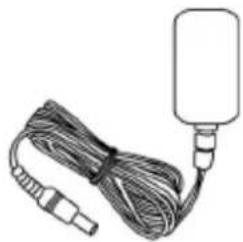
Power Adapter

Access Key 9ard
I-24 LED Status
| LED | Color | Status | Description |
| %ower Red | On | Internet is connected. | |
| Off | The device is off. | ||
| Quick flashing | W%S is active | ||
| Slow flashing | No Internet connection |
I-34 Back Panel
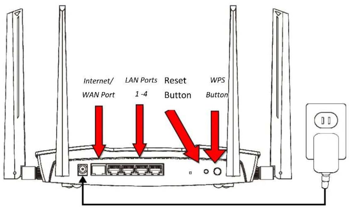
I-5. Safety Information
In order to ensure the safe operation of the device and its users, please read and act in accordance with the following safety instructions.
- The device is designed for indoor use only; do not place it outdoors.
- Do not place the device in or near hot/humid places, such as a kitchen or bathroom.
- Do not pull any connected cable with force; carefully disconnect it from the RA21S.
- Handle the device with care. Accidental damage will void the warranty of the device.
- The device contains small parts which are a danger to small children under 3 years old. %lease keep the device out of reach of children.
- Do not place the device on paper, cloth, or other flammable materials. The device may become hot during use.
- There are no user-serviceable parts inside the device. If you experience problems with the device, please contact your dealer of purchase and ask for help.
- The device is an electrical device and as such, if it becomes wet for any reason, do not attempt to touch it without switching the power supply off. Contact an experienced electrical technician for further help.
I-5. Reset to =actory Default Settings
If you experience problems with your RA21S, you can reset the device back to its factory settings. This resets all settings back to default.
- %ress and hold the WPS/Reset button found on the rear base of the product for at least 19 seconds.
- Release the button when the +ED is flashing blue.
- Wait for the RA21S to restart.
II. Installation
- %lug the included power adapter into the device's 12V DC power port and the other end into an electrical socket.

- Check that the power +ED displays on.

-
Connect the network port of your RA21S to the +AN port of your existing router using an Ethernet cable.
-
Use a Wi-Fi device (e.g. computer, tablet, smartphone) to search for a Wi-Fi network with the SSID “edimax.setup” or “edimax.setup5G” and connect to it.
-
%lease refer to thedefault Wi-Fi SSID and password printed on the Access Key Card to connect Wi-Fi.


iOS 4 or Android 4 and above are required for setup on a smartphone or tablet.
- You can enjoy your Wi-=i now. If you want to change the operating mode and configuration, continue to Browser Based Configuration Interface.
| Wi-=i Router >ode | The device connects to your modem and provides 2.4GHz and/or 5GHz Internet (wireless and Ethernet) access for your network devices. |
| Access Point >ode | The device connects to an existing router via Ethernet cable and provides 2.4GHz and/or 5GHz Internet (wireless and Ethernet) access for your network devices. |
II-14 Wi-=i Router >ode
14 Select whether to use the iQ Setup wizard (recommended) to detect your Internet connection type, or enter the settings manually.

Manual configuration is only recommended for advanced users.
EDIMAX
Wi-Fi Router
The iQ Setup wizard can help detect your Internet connection type, and walk you through setup step-by-step, or you can setup your device manually.
- iQ Setup wizard
- Configure manually
Back
Next
24Connect the blue Internet port of your device to the +AN port of your modem using an Ethernet cable, and then click "Next".
EDIMAX
Wi-Fi Router

Please connect one end of an Ethernet cable to your modem and connect the other end to the Internet port on the router.
Back
Next
- %lease wait a moment while the device tests the connection.

- Click "Next" to continue and configure the device's wireless network.

- Enter a name and password for your 2.4GHz & 5GHz wireless networks, then click "Next" to continue.
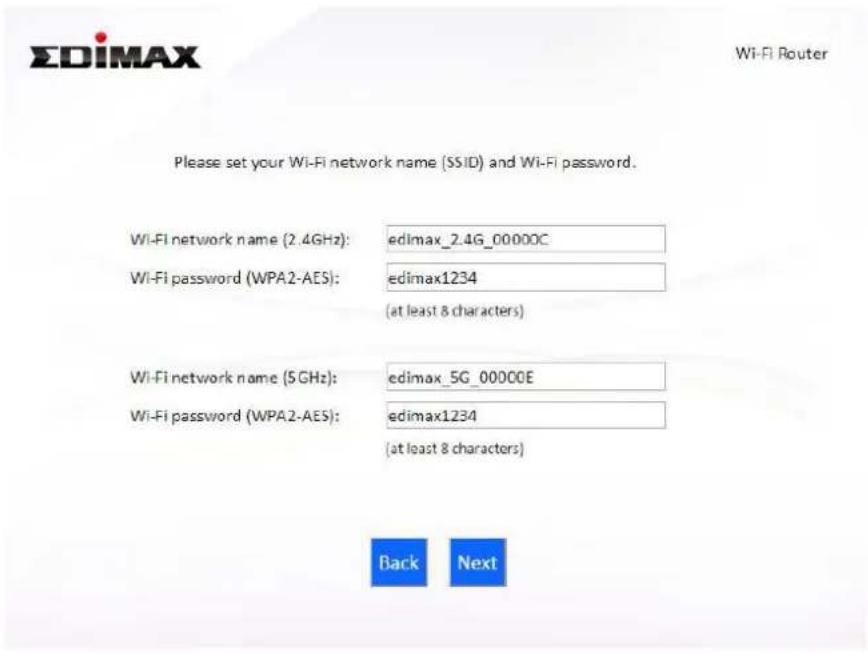
- A summary of your configuration will be displayed, as shown below. Check that all of the details are correct and then click "Next" to proceed.

If you wish to backup the device's settings, click "Backup this configuration" to open a new window and save your current configuration to a .txt file.

- %lease wait while the device applies your settings.

- A final congratulations screen will indicate that setup is complete. You can now connect to the device's new SSID(s) which are shown on the screen then close the browser window.
Congratulations!
You have successfully completed setup. Please connect to the device's new Wi-Fi network name (SSID) listed below. For advanced settings, please access http://edimax.setup from your computer's web browser.
(2.4 GHz) Wi-Fi network name :
Wi-Fi password :
edimax_2.4G_00000C
edimax1234
(5 GHz) Wi-Fi network name :
Wi-Fi password :
edimax_5G_00000E
edimax1234
- The RA21S is working and ready for use. Refer to IV-2. Connecting to a Wi-=i network if you require more guidance.
II-24 Access Point >ode
14 Select "Access %oint" from the top menu and click "Next".
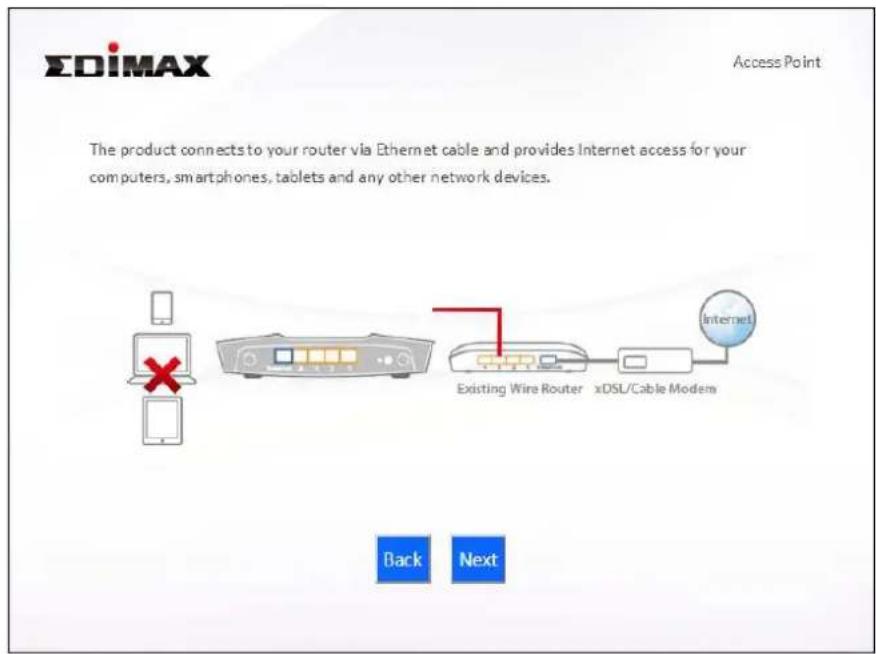
24 Connect the network port of your RA21S to the +AN port of your existing router using an Ethernet cable, then click "Next".

- Select "Obtain an 1% address automatically" or "Use the following 1% address" for your RA21S. If you are using a static 1%, enter the 1% address subnet mask and default gateway. Click "Next" to proceed to the next step.


"Obtain an IP address automatically" is the recommended setting for most users. –or more guidance on static IP addresses, please refer to IV-1. Configuring your IP address.
- Enter a name and password for your 2.4GHz & 5GHz wireless networks, then click "Next" to continue.

- A summary of your configuration will be displayed, as shown below. Check that all of the details are correct and then click "Next" to proceed.


If you wish to backup the device's settings, click "Backup this configuration" to open a new window and save your current configuration to a .txt file.

- %lease wait a moment until the RA21S is ready.

- A final congratulations screen will indicate that setup is complete. You can now connect to the device's new SSID(s) which are shown on the screen then close the browser window.

- The RA21S is working and ready for use. Refer to IV-2. Connecting to a Wi-=i network if you require more guidance.
II-3. Wi-Fi Roaming
Your RA21S supports Wi-Fi roaming. This means if you have other EDIMAX Wi-Fi products which support roaming (e.g. access point, extender) then your Wi-Fi devices (smartphones, tablets etc.) will automatically connect to the best available Wi-Fi signal as you move around or “roam” between them in your home.
To setup other EDI>AX Wi-=i roaming range extender, refer to their included documentation for instructions 4
To setup EDIMAX Wi-Fi roaming extenders with your router/A%, you can simply press the W%Sbutton, as explained below. Ensure both products are within range of each other.
14%ress the W%S buttonon your router/A% for 3 seconds.
24Within two minutes, press and hold the W%S button for 3 seconds on the new extender you would like to add. The extender's green W%S+ED should flash to indicate that W%S is in progress.
34The devices will establish a connection. extender's green W%S+ED should display on for 39 seconds to indicate a successful connection. Your extender is now active with automatic roaming.

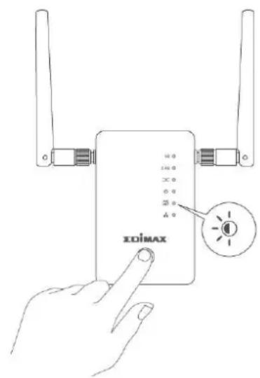
Refer to your EDI>AX roaming Wi-=i extenders documentation for more information4
Browser Based Configuration Interface
After you have setup the RA21S as detailed in II4 Installation or the included Quick Installation Guide, you can use the browser based configuration interface to configure advanced settings.

Please ensure that your computer is set to use a dynamic IP address. Refer to IV-1. Configuring your IP address for more information.
III-14 Login
14 To access the browser based configuration interface enter http://edimax.setup into the UR+ bar of a browser on a network device connected to the same Wi-Fi network as the RA21S.


If you can not access http://edimax.setup, connect the device to a computer using an Ethernet cable and try again.
24 You will be prompted for a username and password. The default username is “admin” and the default password is “1234”.

34 You will arrive at the "Status" screen. Use the menu down the left side to navigate.

III-24 Save Settings
14 After you configure any settings, click the "Apply" button at the bottom of the screen to save your changes.


The device needs to restart in order to bring any changes into effect.
24 Wait a few moments for the device to save the changes and restart with the changes in effect.
Module is reloading Please wait 66 seconds
III-34 >ain >enu
The main menu displays different options depending on your device's operating mode.
Wi-i Router
| Status |
| Setup Wizard |
| Internet |
| LAN |
| 2.4GHz WiFi |
| 5GHz WiFi |
| Schedule |
| Firewall |
| QoS |
| Advanced |
| Toolbox |
Access Point
| Status |
| Setup Wizard |
| LAN |
| 2.4GHz WiFi |
| 5GHz WiFi |
| Schedule |
| Advanced |
| Toolbox |
III-3-14 Status

The "Status" menu displays basic system information about the device, arranged into categories.

Screenshots displayed are examples. The information shown on your screen will vary depending on your configuration.
Status
| System | |
| Model | RG21S |
| Uptime | 1 day 03:37:09 |
| Current Time | 2016/8/4 4:01:00 |
| Hardware Version | Rev. A |
| Boot Code Version | 1.0.0 |
| Runtime Code Version | 0.0.7 |
| >odel | Displays the model number. |
| Uptime | Displays the total time since the device was turned on. |
| Current Time | Displays the current device system time. |
| Hardware Version | Displays the hardware version for reference and support purposes. |
| Boot Code Version | Displays the firmware boot code version. |
| Runtime Code Version | Displays the firmware runtime code version. |
III-3-1-14 Device
2.4G and 5G wireless and +AN status information is summarized in the device page.
2.4G Wireless Configuration
Mode AP
Channel 11
SSID_1
ESS ID matt
Security WPA Pre-shared Key
BSS ID 00:AA:BB:CC:DD:10
5G Wireless Configuration
Mode AP
Channel 36
SSID_1
ESS ID matt5g
Security WPA Pre-shared Key
BSS ID 00:AA:BB:CC:DD:11
LAN Configuration
IP Address 192.168.2.1
Subnet Mask 255.255.255.0
DHCP Server Enabled
MAC Address 00:AA:BB:CC:DD:10
| >ode | Displays the mode. |
| Channel | Displays the channel number the specified wireless frequency is using for broadcast. |
| ESSID | Displays the ESSID (also known as SSID) orwireless network name. |
| Security | Displays the encryption type for the specified SSID. |
| BSSID | Displays the BSSID which is a unique identifier for the device in the network, usually the MAC address. |
| IP Address | Displays the +AN I% address of this device. |
| Subnet >ask | Displays the subnet mask of this device. The default value is 255.255.255.9 |
| DHCP Server | DHC% server is enabled or disabled. |
| >AC Address | Displays the MAC Address of this device. |
III-3-1-2. IPv5
Displays basic 1%v4 related status information.
IPv4
IPv4 Connection Information
| Attain IP Protocol | PPPoE |
| IP Address | 118.165.191.4 |
| Subnet Mask | 255.255.255.255 |
| Default Gateway | 168.95.98.254 |
| MAC Address | 00:AA:BB:CC:DD:20 |
| Primary DNS | 168.95.192.1,168.95.1.1 |
| Attain IP Protocol | Displays the 1% %rotocol used for the WAN 1%v4 connection. |
| IP Address | Displays the WAN 1% address of this device. |
| Subnet >ask | Displays the subnet mask of this device. |
| Default Gateway | Displays the 1% address of the 1%v4 default gateway. |
| >AC Address | 1%v4 MAC address of this device. |
| Primary DNS | %primary DNS servers used by this device. |
III-3-1-3. IPv6
I%v6 standard is not yet widely available. Contact your IS% to check if your Internet supports I%v6.
-IPv6
IPv6 Connection Information
IPv6 Connection Type Link-local only
LAN IPv6 Link-Local Address FE80::2AA:BBFF:FECC:DD10/64
| IPv6 Connection Type | Displays the WAN I%v6 connection type |
| LAN IPv6 Link-Local Address | Displays the +AN I%v6 linl-local I% address |
III-3-24 Setup Wizard

You can run the setup wizard again to reconfigure the basic settings of the device or switch the device to a
different operating mode. Click "Run Wizard" to begin.
Setup Wizard
Switch to Router/Access Point mode
This setup wizard will guide you to switch the device to another mode.
Run Wizard
14 Follow the on-screen instructions to back up your current settings and then reset the device back to its factory default settings.
24 After the device has reset you will see the screen below. Close your browser and open it again.
Reset to Default
You have successfully reset the device to factory defaults. Please close the browser and open it again. This device will start running the setup wizard for you to switch the mode.
34 Follow the on-screen wizard to setup your device in a different mode. Refer to 114 Installation Step: onwards for help if needed.

If you don't see the "Get Started" screen, try reconnecting to the edimax.setup SSI8 and go to http://edimax.setup in a web browser.
III-3-3. Internet

The “Internet” menu provides access to WAN I%v4, WAN I%v6, DDNS and V%N server settings. Click on an item from the submenu to view and/or configure the settings.
III-3-3-1. IPv5
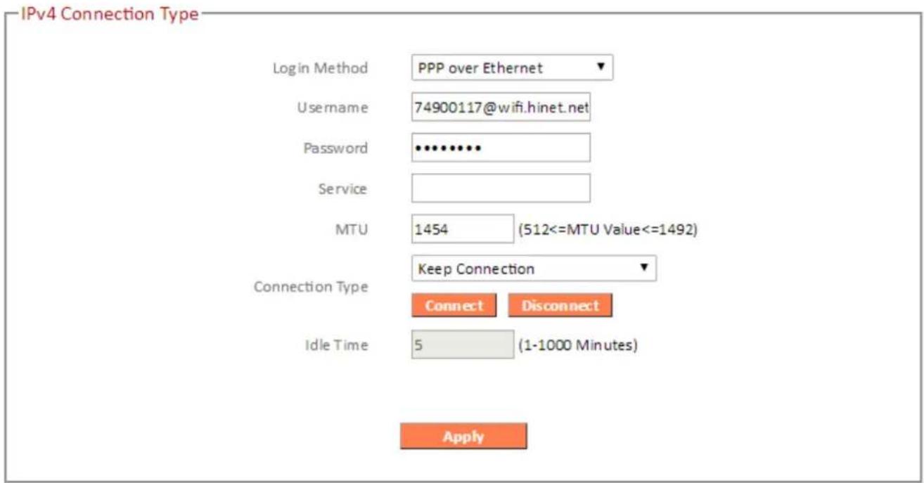
Select a +ogin Method (WAN connection type) and configure the settings. If you are unsure about your login method/connection type, contact your IS%.
III-3-3-1-1. Static IP
Select "Static I%" if your IS% provides Internet access via a fixed I% address. Your IS% will provide you with such information as I% address, subnet mask, gateway address, and DNS address.
IPv4 Connection Type
Login Method
Static IP Address
IP Address
172.1.1.1
Subnet Mask
255.255.255.0
Default Gateway
Primary DNS
Secondary DNS (optional)
Apply
| =fixed IP Address | Input the 1% address assigned by your IS% here. |
| Subnet >ask | Input the subnet mask assigned by your IS% here. |
| 0default Gateway | Input the default gateway assigned by your IS% here. Some IS%s may call this “Default Route”. |
| Primary ONS | Enter the primary DNS address assigned by your IS% here |
| Secondary ONS 9optional) | Enter the secondary DNS address assigned by your IS% here |
III-3-3-1-24 Dynamic IP
Select “Dynamic I%”. If your Internet service provider assigns I% address automatically using DHC% (Dynamic Host Configuration %rotocol).
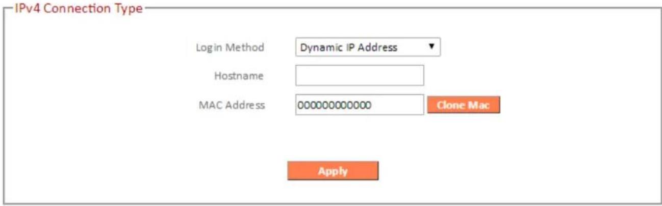
| Host Name | Enter the host name of your computer. |
| >AC Address | For some applications, you may need to designate a specific MAC address for the router. %lease enter the MAC address here. If you are connecting the router to a computer, press “Clone Mac” to automatically enter your computer’s MAC address. |
III-3-3-1-34 PPPoE
Select “%%oE” if your IS% is providing you Internet access via %%oE (%oint-to-%oint %rotocol over Ethernet).

| Username | Enter the user name assigned by your IS% here. |
| Password | Enter the password assigned by your IS%here. |
| >AC Address | For some applications, you may need to designate a specific MAC address for the router. %lease enter the MAC address here. If you are connecting the router to a computer, press “Clone Mac” to automatically enter your computer’s MAC address. |
| Service Name | Give this Internet service a name (optional). |
| >TU | Enter the maximum transmission unit (MTU) value of your network connection. The default value is 1392. |
| Connection Type | Specify a connection type:1. “Keep Connection”: Connected all the time.2. “Automatic Connect/Disconnect”:Connect when you initiate an Internet connection.3. “Manual Connect7Disconnect”: Connect7disconnect manually using the “Connect” and “Disconnect” buttons. |
| ’dle-Pime- | Specify the amount of time the router waits before shutting down an idle connection. Only available when “Connect on Demand” (above) is selected. |
III-3-3-1-5. PPTP
Select “%%T%” if your IS% is providing you Internet access via %%T% (%oint-to-%oint Tunneling %rotocol). Then select “Obtain an I% address automatically” or “Use the following I% address” depending on your IS%p
IPv4 Connection Type
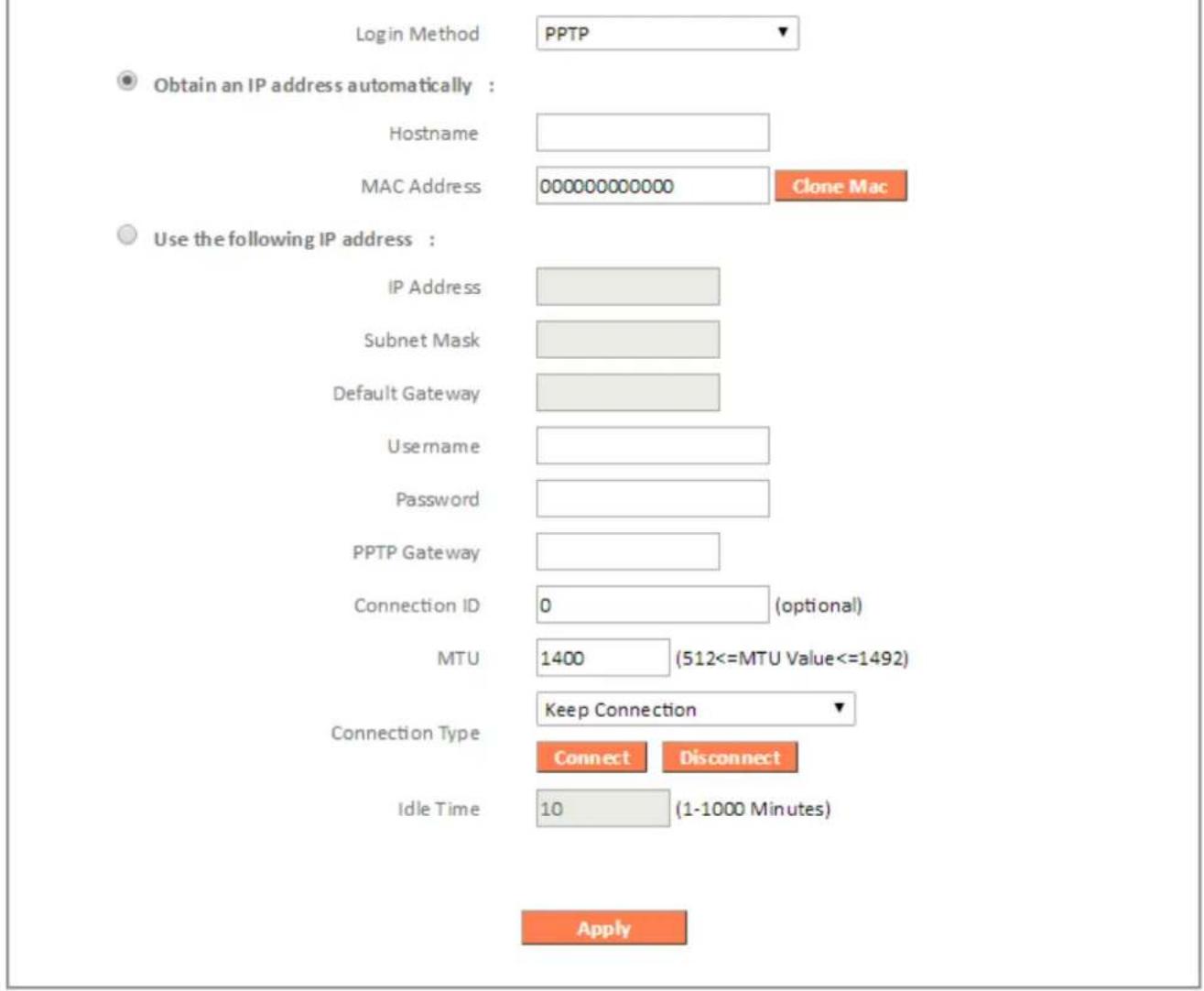
| :ost -Name- | Enter the host name of your computer here If required. |
| >)C-)ddress - | For some applications, you may need to designate a specific MAC address for the router. %lease enter the MAC address here. If you are connecting the router to a computer, press “Clone Mac” to automatically enter your computer’s MAC address. |
| ’P-)ddress - | Input the 1% address assigned by your IS% here. |
| Subnet->ask - | Input the subnet mask assigned by your IS% here. |
| Default--ateway - )ddress - | Input the default gateway assigned by your IS% here. Some IS%s may call this “Default Route”. |
| ysername - | Input the user name assigned by your IS% here. |
| Password- | Input the password assigned by your IS% here |
| PPPP--ateway- | Input the %%T% gateway assigned by your IS% her |
| Connection-'0- | Specify a reference name/ID for the connection. |
| >Py - | Enter the maximum transmission unit (MTU) value of your network connection. The default value is 1392. |
| Connection-Pype- | Specify a connection type:“Keep Connection”: Connected all the time.“Automatic Connect/Disconnect”: Connect when you initiate an Internet connection.“Manual Connect/Disconnect”:Connect/disconnect manually using the “Connect” and “Disconnect” buttons. |
| ’dle-Pime- | Specify the amount of time the router waits before shutting down an idle connection. Only available when “Connect on Demand” (above) is selected. |
III-3-3-1-5. L2TP
Select “+2T%” if your IS% is providing you Internet access via +2T% (+ayer 2 Tunneling %rotocol).p
- IPv4 Connection Type

| Host Name | Enter the host name of your computer here If required. |
| >AC Address | For some applications, you may need to designate a specific MAC address for the router. %lease enter the MAC address here. If you are connecting the router to a computer, press “Clone Mac” to automatically enter your computer’s MAC address. |
| IP Address | Input the 1% address assigned by your IS% here. |
| Subnet >ask | Input the subnet mask assigned by your IS% here. |
| Default Gateway | Input the default gateway assigned by your IS%here. Some IS%s may call this “Default Route”. |
| Username | Input the user name assigned by your IS% here. |
| Password | Input the password assigned by your IS% here. |
| L2TP Gateway | Input the +2T% gateway assigned by your IS% here |
| >TU | Enter the maximum transmission unit (MTU) value of your network connection. The default value is 1392. |
| Connection Type | Specify a connection type:“Keep Connection”: Connected all the time.“Automatic Connect/Disconnect”: Connect when you initiate an Internet connection.“Manual Connect/Disconnect”:Connect/disconnect manually using the “Connect” and “Disconnect” buttons. |
| Idle Time | Specify the amount of time the router waits before shutting down an idle connection. Only available when “Connect on Demand” (above) is selected. |
III-3-3-1-6. Russia L2TP 9Dual-Access)
Select “+2T%” if your IS% is providing you Internet access via +2T% (+ayer 2 Tunneling %rotocol).p
- IPv4 Connection Type

| >ulti WAN Bridge Port | Check which +AN port to bridge for multi-WAN. |
| Host Name | Enter the host name of your computer here If required. |
| >AC Address | For some applications, you may need to designate a specific MAC address for the router. %lease enter the MAC address here. If you are connecting the router to a computer, press “Clone Mac” toautomatically enter your computer's MAC address. |
| IP Address | Input the 1% address assigned by your IS% here. |
| Subnet >ask | Input the subnet mask assigned by your IS% here. |
| Default Gateway | Input the default gateway assigned by your IS% here. Some IS%s may call this “Default Route”. |
| Username | Input the user name assigned by your IS% here. |
| Password | Input the password assigned by your IS% here. |
| L2TP Gateway | Input the +2T% gateway assigned by your IS% here |
| >TU | Enter the maximum transmission unit (MTU) value of your network connection. The default value is 1392. |
| Connection Type | Specify a connection type:4. “Keep Connection”: Connected all the time.5. “Automatic Connect/Disconnect”: Connect when you initiate an Internet connection.6. “Manual Connect/Disconnect”:Connect/disconnect manually using the “Connect” and “Disconnect” buttons. |
| Idle Time | Specify the amount of time the router waits before shutting down an idle connection. Only available when “Connect on Demand” (above) is selected. |
III-3-3-1-7. DS-Lite
Dual-stack lite (DS-+ite) is a technology that enables Internet service providers to move to an 1%v6 network while simultaneously handling 1%v4 address depletion. The DS-+ite architecture uses 1%v6-only links between the provider and the user while maintaining the 1%v4 (or dual-stack) hosts in the user network.

Refer to your IS% or network administrator for help configuring DS-+ite.
III-3-3-2. IPv6
Select a +ogin Method (WAN connection type) and configure the settings. If you are unsure about your login method/connection type, contact your IS%

9check with your ISP for correct IPv6 configuration.
IPv6 Connection Type

III-3-3-2-1. Static IP
Select "Static I%" if your IS% provides Internet access via a fixed I% address. Your IS% will provide you with such information as I% address, subnet mask, gateway address, and DNS address.

9heck with your ISP for correct IPv6 configuration.

| Use Link-Local Address | Check the box to use a link-local address. |
| IPv6 Address | Input the 1%v6 address assigned by your IS% here. |
| Subnet Prefix Length | Specify the prefix length for the subnet. |
| Default Gateway | Input the default gateway assigned by your IS% here. Some IS%s may call this “Default Route”. |
| Primary IPv6 DNS Address | Enter the primary DNS address assigned by your IS% here |
| Secondary IPv6 DNS | Enter the secondary DNS address assigned by |
| Address | your IS% here |
| LAN IPv6 Address | Enter the +AN I%v6 address |
| LAN IPv6 Link-Local Address | If using link-local I%v6 address, it's displayed here. |
| IPv6 Auto Address Allocation | Enable or disable auto address allocation for I%v6. Select your autc-configuration type |
| Auto-configuration Type | Select your auto-configuration type.Stateless: DNS server information is received from DHC%v6 server but address is generated separately.Stateful: DNS server information and address are received from DHC%v6 server |
| Router Advertisement Lifetime | Time in seconds this router should be used as the default router. 9 tells the host this router should not be used as the default. |
III-3-3-2-24 PPPoE
Select “%%oE” if your IS% is providing you Internet access via %%oE (%oint-to-%oint %rotocol over Ethernet).
IPv6 Connection Type
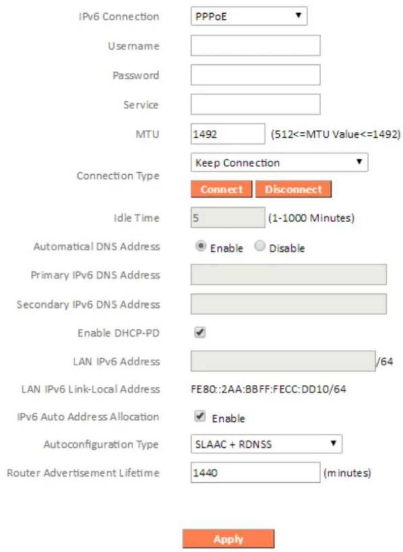
| Username | Enter the user name assigned by your IS% here. |
| Password | Enter the password assigned by your IS%here. |
| >AC Address | For some applications, you may need to designate a specific MAC address for the router. %lease enter the MAC address here. If you are connecting the router to a computer, press “Clone Mac” to automatically enteryour computer's MAC address. |
| Service Name | Give this Internet service a name (optional). |
| >TU | Enter the maximum transmission unit (MTU) value of your network connection. The default value is 1392. |
| Connection Type | Specify a connection type:4. “Keep Connection”: Connected all the time.5. “Automatic Connect/Disconnect”: Connect when you initiate an Internet connection.6. “Manual Connect/Disconnect”: Connect/disconnect manually using the “Connect” and “Disconnect” buttons. |
| Idle Time | Specify the amount of time the router waits before shutting down an idle connection. Only available when “Connect on Demand” (above) is selected. |
| Automatic DNS Address | Enable or disable automatic DNS address. |
| Primary IPv6 DNS Address | Enter the primary DNS address assigned by your IS% here |
| Secondary IPv6 DNS Address | Enter the secondary DNS address assigned by your IS% here |
| Enable DHCP-PD | Enable or disable DHC% prefix delegation for the DHC%v6 server |
| LAN IPv6 Address | Enter the +AN I%v6 address |
| LAN IPv6 Link-Local Address | If using link-local I%v6 address, it’s displayed here. |
| IPv6 Auto Address Allocation | Enable or disable auto address allocation for I%v6. Select your autc-configuration type |
| Auto-configuration Type | Select your auto-configuration type.Stateless: DNS server information is received from DHC%v6 server but address is generated separately.Stateful: DNS server information and address are received from DHC%v6 server |
| Router | Time in seconds this router should be used as |
| AdvertisementLifetime | the default router. 9 tells the host this router should not be used as the default. |
III-3-3-2-3. Auto-configuration
Auto-configuration allow various devices attached to an 1%v6 network to connect to the Internet using Stateless Auto-configuration without requiring intermediate 1% support in the form of a DHC% server.

| Automatic DNS Address | Enable or disable automatic DNS address. |
| Primary IPv6 DNS Address | Enter the primary DNS address assigned by your IS% here |
| Secondary IPv6 DNS Address | Enter the secondary DNS address assigned by your IS% here |
| Enable DHCP-PD | Enable or disable DHC% prefix delegation for the DHC%v6 server |
| LAN IPv6 Address | Enter the +AN I%v6 address |
| LAN IPv6 Link-Local Address | If using link-local I%v6 address, it's displayed here. |
| IPv6 Auto Address Allocation | Enable or disable auto address allocation for I%v6. Select your auto-configuration type |
| )uto -configuration Type | Select your auto-configuration type.Stateless: DNS server information is received from DHC%v6 server but address is generated separately.Stateful: DNS server information and address are received from DHC%v6 server |
| Router )dvertisement Lifetime | Time in seconds this router should be used as the default router. 9 tells the host this router should not be used as the default. |
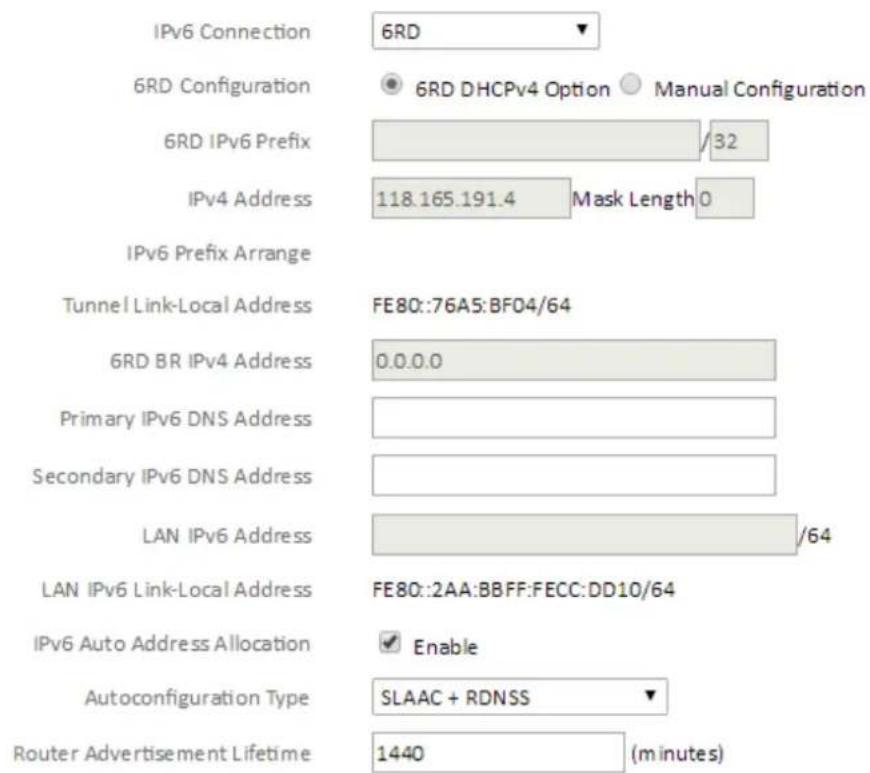
III-3-3-2-4. 6rd
6rd facilitates rapid deployment of 1%v6 across IS%'s 1%v4 infrastructures.
IPv6 Connection Type
Apply
| 6rd Configuration | Select to configure 6rd with DHC%v4 server or manually. When manual is selected, enter the information in the fields below. |
| 6rd IPv6 Prefix | Enter the I%v6 prefix. |
| IPv4 Address | Specify the I%v4 address and mask length. |
| IPv6 Prefix Arrange | Displays the prefix arrangement. |
| Tunnel Link-Local Address | Displays link-local tunnel address. |
| 6rd BR IPv4 Address | Input the 6rd BR I%v4 address. |
| Primary IPv6 DNS Address | Enter the primary DNS address assigned by your IS% here |
| Secondary IPv6 DNS | Enter the secondary DNS address assigned by |
| Address | your IS% here |
| LAN IPv6 Address | Enter the +AN I%v6 address |
| LAN IPv6 Link-Local Address | If using link-local I%v6 address, it's displayed here. |
| IPv6 Auto Address Allocation | Enable or disable auto address allocation for I%v6. Select your autc-configuration type |
| Auto-configuration Type | Select your auto-configuration type.Stateless: DNS server information is received from DHC%v6 server but address is generated separately.Stateful: DNS server information and address are received from DHC%v6 server |
| Router Advertisement Lifetime | Time in seconds this router should be used as the default router. 9 tells the host this router should not be used as the default. |
III-3-3-2-5. Link-local
A link-local address is a network address for communications only within the broadcast domain or network segment that the host is connected to.

| LAN IPv6 Link-Local Address | If using link-local 1%v6 address, it’s displayed here. |
III-3-3-34 DDNS
Dynamic DNS (DDNS) is a service which provides a hostname-to-I% service for dynamic I% users. The changing nature of dynamic I%s means that it can be difficult to access a service provided by a dynamic I% user; a DDNS service though can map such dynamic I% addresses to a fixed hostname, for easier access. The router supports several DDNS service providers, for more details and to register for a DDNS account please visit the DDNS providers website(s), examples of which are listed below.
DDNS
Enable / Disable
Provider
Domain Name
Account / E-mail
Password / Key
○ Enable ● Disable
DynDNS



Save Settings
| Enable/Disable | Enable or disable DDNS |
| Provider | Select DDNS service provider. |
| Domain Name | Enter the domain name provided by the DDNS provider. |
| Account/Email | %lease enter the DDNS registration account/email. |
| Password/Key | Enter the DDNS service password/key. |
The following DDNS services are supported:
A V%N is a virtual private network which you can connect to remotely. V%Ns are secure and encrypted. Your router has a built-in V%N server which you can configure and access on your network devices, including smartphones, tablets and computers.


- Enable V%N server.
- Export your V%N server configuration file. You can oper this file on your network device (smartphone, tablet, computer) using V%N software7app to automatically connect to your V%N on your device.

You can choose which kind of configuration file to export, depending on your requirement. "Send All Traffic Over VPN
Server" will configure your network device to use the VPN for all Internet traffic. "Send Only Home Network Traffic over VPN Server" will configure your network device to access the Internet as usual but use the VPN to access your home (router) network. The 3nd option is ideal if you only wish to use the VPN for remote access to your home network. The 1st option will encrypt all Internet traffic through the VPN.
- Setup a login account for your V%N. This is required to access your V%N or your network device.
- Send the exported configuration file to your network device (e.g. via email, cloud or USB). Open the file using V%N software or apps which are widely available online, and enter your login details to connect to your V%N.

You can access further help to connect your network device to your VPN by selecting your operating system under "OpenVPN 9client Settings".
III-3-4. LAN

You can configure your +ocal Area Network (+AN) on this page. You can enable the router to dynamically allocate 1% addresses to your +AN clients, and you can
modify the 1% address of the device. The device's default 1% address is 192.168.2.1.

You can access the browser based configuration interface using the device's IP address instead of using the URL http://edimax.setup.
LAN IP
IP Address
192.168.2.1
Subnet Mask
255.255.255.0
802.1d Spanning Tree
Disable ▼
| IP Address | Specify the 1%address here. This 1% address will be assigned to the RA21S and will replace the default 1% address |
| Subnet >ask | Specify a subnet mask. The default value is 255.255.255.0 |
| 802.1d Spanning Tree | Select “Enable” or “Disable” to enable/disable 802.1d Spanning Tree. This creates a tree of connected layer-2 bridges (typically Ethernet switches) within a mesh network, and disables those links that are not part of the tree, leaving a single active path between any two network nodes. |
Your device's DHC% server automatically assigns 1% addresses to computers on its network, between a defined range of numbers.

| 0:CP -Server-?ease-Pime- | Enable or disable the DHC% server. |
| Select a lease time for the DHC% leases here.The DHC% client will obtain a new 1% address after the period expires. | |
| Start-'P- | Enter the start 1% address for the DHC% server's 1% address leases |
| #nd-'P- | Enter the end 1% address for the DHC% server's 1% address leases |
| ONS- | Select whether to get DNS addresses dynamically from IS% or manually enter DNS addresses. |
| Primary-ONS-)ddress - | When Static 1% is selected above, enter the primary DNS address here. |
| Secondary-ONS-)ddress - | When Static 1% is selected above, enter the secondary DNS address here. |

The LAN IP page will be displayed as below when your device is set to access point mode. You can set the RA31S to obtain an IP address automatically or you can specify an IP address.
LAN IP
Bridge Type
Dynamic IP ▼
IP Address
192.168.2.1
IP Subnet Mask
255.255.255.0
Default Gateway
0.0.0.0
DNS
Dynamic IP ▼
802.1d Spanning Tree
Disabled ▼
III-3-5. 2.4GHz Wireless & 5GHz Wireless

The “2.4GHz WiFi” & “5GHz WiFi” menu allows you to configure SSID and security settings for your Wi-Fi network along with a guest Wi-Fi network or (access point mode only) multiple SSIDs. W%S, access control and scheduling functions can also be managed from here. You can quickly enable7disable the 2.4GHz or
5GHz Wi-Fi from this screen.

In Access Point mode you can configure Multiple SSI85. Refer to
Basic: Access Point Mode below.

III-3-5-1. Basic
The "Basic" screen displays settings for your 2.4GHz or 5GHz Wi-Fi networks.
Basic
Mode
AP ▼
Band
2.4 GHz (802.11b/g/n) ▼
Guest Network
Enabled
Disabled
Guest IP Address
192.168.170.1
Guest Subnet Mask
255.255.255.0
Guest Lease time
One week ▼
Guest Start IP
192.168.170.100
Guest End IP
192.168.170.200
SSID
m att
Guest SSID
∴ m = 3/11
Channel
Auto ▼
Apply
| >ode | Keep the default “AP” value for the device to act as a standard wireless access point. |
| Band | Displays the wireless standard used for the RA21S’s “2.4GHz (B+G+N)” means that 802.11b, 802.11g, and 802.11n wireless clients can connect to the RA21S. |
| Guest Network | You can setup an additional “Guest” Wi-Fi network so guest users can enjoy Wi-Fi connectivity without accessing your primary network. Enable or disable here. |
| Guest IP Address | Set the guest network IP address. |
| Guest Subnet >ask | Set the guest network subnet address. |
| Guest Lease Time | Set the lease time for the DHCP server for IP addresses on the guest network. |
| Guest Start IP | Set the start IP address for the DHCP server range for guest IP addresses. |
| Guest End IP | Set the end IP address for the DHCP serverrange for guest IP addresses. |
| SS'0- | This is the name of your Wi-Fi network for identification, also sometimes referred to as “SSID”. The SSID can consist of any combination of up to 32 alphanumerical characters. |
| -uest-SS'0- | This is the name of yourguestWi-Fi network for identification, also sometimes referred to as “SSID”. The SSID can consist of any combination of up to 32 alphanumerical characters. |
| Channel-Number- | Select a wireless radio channel or use the default “Auto” setting from the drop-down menu. |
)ccess-Point->ode-
The “Basic” screen displays settings for your 2.4GHz or 5GHz Wi-Fi networks and you can configure multiple SSIDs by clicking the >ultiple SS'0 button.
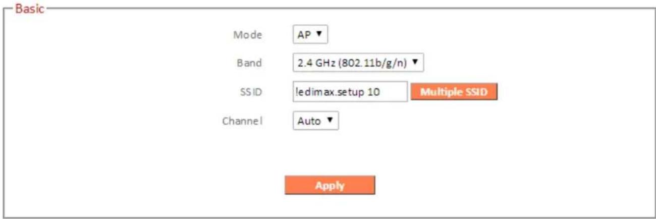
| >ode - | Keep the default “AP” value for the device to act as a standard wireless access point. |
| Band- | Select the wireless standard used for the RA21S’s “2.4GHz (B+G+N)” means that 802.11b, 802.11g, and 802.11n wireless clients can connect to the RA21S. |
| SS’0- | Set the SSID name for your access point’s Wi-Fi network. Click the >ultiple SS’0 button to setup multiple SSIDs (below). |
| Channel- | Select a wireless radio channel or use the default “Auto” setting from the drop-down |
menu.
Basic

Apply
Cancel
| > multiple SSIO # | Enable or disable up to four additional SSIDs. Security for each SSID can be configured in the Security menu. |
| SSIO # | Set the SSID (wireless network) name for the specified SSID number. |
III-3-5-2. Security
Configure the security settings for Wi-Fi and guest Wi-Fi networks. Select SSID and then setup the encryption type.

| SSID Selection | Select which SSID to configure the security settings for. |
| Broadcast ESSID | Broadcast or hide SSID. When broadcast, the SSID will be visible to clients as an available Wi-Fi network. When not broadcast, the SSID will not be visible as an available Wi-Fi network to clients – clients must manually enter the SSID in order to connect. A hidden SSID is typically more secure than a visible SSID. |
| W>> | WMM (Wi-Fi Multimedia) technology can improve the performance of certain network applications, such as audio/video streaming, network telephony (Vol%) and others. When WMM is enabled, the device will prioritize different kinds of data and give higher priority to applications which require instant responses for better performance. |
| Encryption | Select an encryption type from the drop-down menu:p |

"WPA Pre-shared Key" is the recommended and most secure encryption type.

In WISP mode, WPA RA8IUS is unavailable for the wireless band that is used to connect to WISP's AP.
Encryption is disabled and no password/key is required to connect to the RA21S.

8isabling wireless encryption is not recommended. When disabled, anybody within range can connect to your device's SSI8.
| Enable 802.1x Authentication | Check the box to enable the 892.1x authentication. A RADIUS server is required to perform 892.1x authentication: enter the RADIUS server's information in the relevant fields (below). |

Enable 802.1x Authentication
RADIUS Server IP address
RADIUS Server Port
RADIUS Server Password
1812
III-3-5-2-2. WEP
WE% (Wired Equivalent %rivacy) is a basic encryption type. For a higher level of security consider using W%A encryption.
| Authentication Type | Open System, Shared Key, Auto authentication types are available. |
| Key Length | Select 64-bit or 128-bit. 128-bit is more secure than 64-bit. |
| Key Type | Choose from “ASCII” (any alphanumeric character 0-9, a-z and A-Z) or “Hex” (any characters from 0-9, a-f and A-F). |
| Default Key | Select which encryption key (1 – 4 below) is the default key. For security purposes, you can set up to four keys (below) and change which is the default key. |
| Encryption Key 1 - 4 | Enter your encryption key/password according to the format you selected above. |
| Enable 802.1x Authentication | Check the box to enable the 802.1x authentication. A RADIUS server is required to perform 802.1x authentication: enter the RADIUS server's information in the relevant fields. |
III-3-5-2-3. WPA Pre-Shared Key
W%A pre-shared key is the recommended and most secure encryption type.
| WPA Type | Select from W%A (TKI%), W%A2 (AES) or W%A Mixed. W%A2 (AES) is safer than W%A (TKI%), but not supported by all wireless clients. %lease make sure your wireless client supports your selection. W%A2 (AES) is recommended followed by W%A2 Mixed if your client does not support W%A2 (AES). |
| Pre-shared Key Type | Choose from “%assphrase” (8-63 alphanumeric characters) or “Hex” (up to 64 characters from 0-9, a-f and A-F). |
| Pre-shared Key | %leaseenter a key according to the format you selected above. A complex, hard-to-guess key is recommended. Check the “Hide” box to hide your password from being displayed on-screen. |
III-3-5-2-4. WPA Radius
W%A RADIUS is a combination of W%A encryption and RADIUS user authentication. If you have a RADIUS authentication server, you can authenticate the identity of every wireless client against a user database.
| WPA Type | Select from W%A (TKI%), W%A2 (AES) or W%A Mixed. W%A2 (AES) is safer than W%A (TKI%), but not supported by all wireless clients. %lease make sure your wireless client supports your selection. W%A2 (AES) is recommended followed by W%A2 Mixed if your client does not support W%A2 (AES). |
| RADIUS Server IP address | Input the I% address of the RADIUS authentication server here. |
| RADIUS Server Port | Input the port number of the RADIUS authentication server here. The default value is 1812. |
| RADIUS Server Password | Input the password of the RADIUS authentication server here. |
III-3-5-3. WPS
Wi-Fi %protected Setup is a simple way to establish connections between W%S compatible devices. W%S can be activated on compatible devices by pushing a W%S button on the device or from within the device's firmware7configuration interface. When W%S is activated in the correct manner and at the correct time for two compatible devices, they will automatically connect. %IN code W%S includes the use of a %IN code between the two devices for verification.
WPS

| WPS | Check7uncheck this box to enable7disable W%S |
| PIN =unction | Check7uncheck this box to enable7disable %IN code W%S. |
| WPS Current Status | Displays “Configured” or “unConfigured” depending on whether W%S and SSID7security settings for the device have been configured or not, either manually or using the W%S button. |
| Self PIN Code | Displays the W%S %IN code of the device. |
| SSID | Displays the SSID of the device. |
| Authentication >ode | Displays the wireless security authentication mode of the device. |
| Passphrase Key | Displays the wireless security authentication key. |
| WPS via PushButton- | Click “Start to %rocess” to activate W%S on theaccess point. W%S will be active for 2 minutes. |
| kPS -via-P’N- | Enter the wireless client’s %IN code here and click “Start to %rocess” to activate %IN code W%S. Refer to your wireless client’s documentation if you are unsure of its %IN code. |
III-3-6. Schedule
The schedule feature allows you to automate the wireless network for specified times. Check/uncheck the box “Enable Schedule” to enable/disable the wireless scheduling function.

The RA31S must have time & date settings initially set to use scheduling.
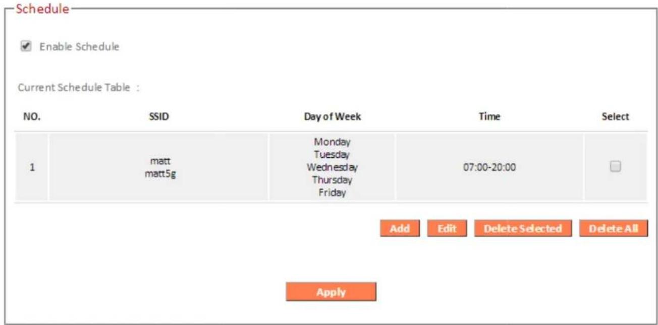

Wireless scheduling can save energy and increase the security of your network.
- Check Enable and use the Select, Add, Edit or Delete checkboxes to select and modify schedule(s).
- When you click Add, specify day(s), start time and end time for the schedule using the drop-down menus and click Apply.
| 2.4GHz SSID | 5GHz SSID | ||||||
| ✓ | matt | ✓ | matt5g | ||||
| Sunday | Monday | Tuesday | Wednesday | Thursday | Friday | Saturday | |
| ☐ | ✓ | ✓ | ✓ | ✓ | ✓ | ☐ | |
| Start Time | End Time | ||||||
| 07 ▼ : 00 ▼ | 20 ▼ : 00 ▼ | ||||||

34 Remember to Apply your changes and make sure Enable is checked.

III-3-7. =irewall
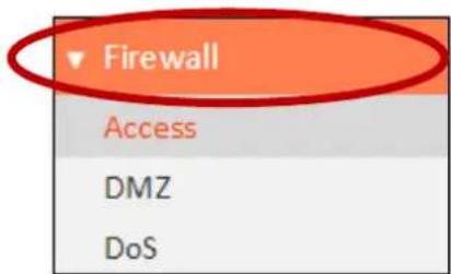
The “Firewall” menu provides access to access control, DMZ and DoS functions to improve the security of your wireless network.

| Enable or Disable=irewall >odule=unction | Enable or disable the Stateful %acketInspection (S%I) firewall. |
III-3-7-1. Access
p
Access Control is a security feature that can help to prevent unauthorized users from connecting to your wireless router.
This function allows you to define a list of network devices permitted or denied to connect to the RA21S. Devices are each identified by their unique MAC address or 1% address. Specific services can also be allowed/denied for 1% addresses.
Check/uncheck the “Enable MAC Filtering” and/or “Enable I% Filtering” box to enable/disable MAC filtering and/or I% filtering.
Access

Enable MAC Filtering : ☑ Deny ☐ Allow
Client PC MAC Address

Comment

Add
Reset
MAC Filtering table :
NO.
Client PC MAC Address
Comment
Select
1
80:1F:02:9C:8F:FF
filter_comment

Delete Selected
Delete All
Reset

Enable IP Filtering Table : ☑ Deny ☑ Allow
NO.
PC Description

Deny Allow
PC IP Address
Client Service
Protocol
Port Range
Select
1
Home
192.168.2.115
WWW E-mail Sending
TCP
TCP Port: 80,3128,8000,8080,8081, 25

Add
Delete Selected
Delete All
Reset
Apply
p
MA9 -iltering:
| #nable->)C-=iltering- | Check the box to enable MAC filtering and select whether to “Deny” or “Allow” access for specified MAC address. |
| Client-PC->)C-)ddress- | Enter a MAC address of computer or network device manually without dashes or colons e.g. for MAC address ‘aa-bb-cc-dd-ee-ff’ enter ‘aabbccddeeff’. |
| Comment- | Enter a comment for reference/identification consisting of up to 16 alphanumerical characters. |
| )dd - | Click “Add” to add the MAC address to the MAC address filtering table. |
MAC address entries will be listed in the table. Select an entry using the "Select" checkbox.
| 0elete-Selected-&-0elete-)II - | Delete selected or all entries from the table. |
IP -iltering:
| #nable-IP-=ilterinξ- | Check the box to enable 1% filtering and select whether to “Deny” or “Allow” access for specified 1% address |
| )dd-PC - | Opens a new window to add a new 1% to the list, to deny or allow access/services according to above. |
This page allows users to define service limitation of client PC, including IP address and service type.

Client Service :
| Service Name | Detail Description | Select |
| WWW | HTTP, TCP Port 80, 3128, 8000, 8080, 8081 | |
| E-mail Sending | SMTP, TCP Port 25 | |
| News Forums | NNTP, TCP Port 119 | |
| E-mail Receiving | POP3, TCP Port 110 | |
| Secure HTTP | HTTPS, TCP Port 443 | |
| File Transfer | FTP, TCP Port 21 | |
| MSN Messenger | TCP Port 1863 | |
| Telnet Service | TCP Port 23 | |
| AIM | AOL Instant Messenger, TCP Port 5190 | |
| NetMeeting | H.323, TCP Port 389,522,1503,1720,1731 | |
| DNS | UDP Port 53 | |
| SNMP | UDP Port 161, 162 | |
| VPN-PPTP | TCP Port 1723 | |
| VPN-L2TP | UDP Port 1701 | |
| TCP | All TCP Port | |
| UDP | All UDP Port |
User Define Service :


| Client-PC-Oescription - | Enter a description for reference/identification of up to 16 alphanumeric characters. |
| Client-PC-'P-address- | Enter a starting 1% address in the left field and the end 1% address in the right field to define arange of I% addresses;or enter an I% address in the left field only to define a single I% address |
| Service-Name- | Various services are listed here with a short description. Check/uncheck the box for each service you wish to select. |
| Protocol- | Select protocol “TC%” or “UD%” or “Both” for a service not included in the “Client %C Service” list. |
| Port-Range- | Enter the port range for the service not included in the “Client %C Service” list.Enter a single port number e.g. 119, a range of port numbers e.g. 119-129, or multiple port numbers separated by a comma e.g. 119,115,129. |
| )dd - | Click “Add” to add selected services or a user defined service to the I%filtering table. |
III-3-7-2. D>Z
A Demilitarized Zone (DMZ) is an isolated area in your local network where private 1% addresses are mapped to specified Internet 1% addresses, allowing unrestricted access to the private 1% addresses but not to the wider local network.
You can define a virtual DMZ host here. This is useful for example, if a network client %C cannot run an application properly from behind an NAT firewall, since it opens the client up to unrestricted two-way access.

| Enable D>Z | Check/uncheck the box to enable/disable the device's DMZ function. |
| Public | Select “Dynamic I%” or “Static I%” hereFor “Dynamic I%” select an Internet connection session from dropdown menu.For “Static I%” enter the I% address that you want to map to a specific private I% address |
| Client PC | Enter the private I% address that the internet I% address will be mapped to. |
| Add | Click “Add” to add the client to the “Current |
DMZ Table".
DMZ entries will be displayed in the table shown below:

| Delete Selected/Delete All | Delete selected or all entries from the table. |
III-3-7-3. DoS
Denial-of-Service (DoS) is a common form of malicious attack against a network. The router's firewall can protect against such attacks.
If you are not familiar with these functions, it is recommended you keep the default settings.

| Ping-of-0eath- | Specify the frequency of ping of death packets which will trigger the router's DoS protection function. |
| Oiscard-Ping-from-κ)N - | Check this box and the router will not answer ping requests from the Internet. |
| Port-Scan- | Intruders use “port scanners” to detect open Internet 1% address ports. Check each type of port scan to prevent. |
| Sync-=lood- | Specify the frequency of sync flood packets which will trigger the DoS protection function. |
III-3-8. QoS

Quality of Service (QoS) is a feature to manage Internet bandwidth efficiently. Some applications
require more bandwidth than others to function properly, and QoS allows you to ensure that sufficient bandwidth is available. Minimum or maximum bandwidth can be guaranteed for a specified application.

QoS can improve the RA31S's performance. QoS is recommended to optimize performance for online gaming.
III-3-8-1. QoS
Check/uncheck the box "Enable QoS" to enable/disable the QoS function. Click "Add" to open a new window and setup a QoS rule. The "Current QoS Table" displays all QoS rules.
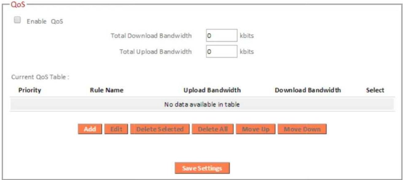
| Total Download Bandwidth | Enter your total download bandwidth limit from your Internet service provider (IS%) in kbits. |
| Total Upload Bandwidth | Enter your total upload bandwidth limit from your Internet service provider (IS%) in kbits |
| Add | Opens a new window to add a new QoS rule to the current QoS table. |


| Rule-Name- | Enter a name for the QoS rule for reference/identification. |
| Bandwidth- | Set the bandwidth limits for the QoS rule: Bandwidth: Download Kbps guarantee (1) (2) (3) 1. Select “Download” or “Upload” for the QoS rule. 2. Enter the bandwidth limit. 3. Select whether the bandwidth is a “Guarantee” (minimum) or “Max” (maximum). |
| ?ocal-'P-)address- | Enter the I% address range to which the QoS rule will be applied. Enter a starting I% address in the left field and the end I% address in the right field to define a range of I% addresses; or enter an I% address in the left field only to define a single I% address |
| ?ocal-Port-Range-Remote-IP-)ddress - | Enter the port range to activate the QoS rule. Enter a single port number e.g. 119 or a range of port numbers e.g. 119-129Enter the remote I% address rangewhich will activate the QoS rule.Enter a starting I% address in the left field and the end I% address in the right field to define a range of I% addresses;or enter an I% address in the left field only to define a single I% address |
| Remote-Port-Range- | Enter the remote port range to activate the QoS rule.Enter a single port number e.g. 110 or a range of port numbers e.g. 110-120 |
| Traffic-Type- | Select traffic type as an alternative to specifying a port range above. |
| Protocol- | Select a “TC%” or “UD%” protocol type. |
| Save- | Click ‘add’ button to add a new QoS rule (detailed instructions will be given below). |
QoS rule entries will be listed in the “Current QoS Table” as shown below. Select a rule using the “Select” checkbox.

When using the "Edit" button only one rule can be selected each time.

QoS rules will be processed in the order that they are listed i.e. the rule at the top of the list will be applied first, and then the second rule etc. The order can be adjusted using the “Move Up/8own” buttons.
Current QoS Table :
| Priority | Rule Name | Upload Bandwidth | Download Bandwidth | Select | ||||
| Add | Edit | Delete Selected | Delete All | Move Up | Move Down | |||
| #dit- | Edit a selected rule. |
| 0delete-Selected&0delete-)ll - | Delete selected or all entries from the table. |
| >ove-Up&0own- | Move selected rule up or down the list. |
III-3-9. Advanced

Advanced features of the RA21S can be configured from the “Advanced” menu.
III-3-9-1. Static Routing
Static routing is a method of configuring path selection of routers, characterized by the absence of communication between routers regarding the current topology of the network. The opposite of static routing is dynamic routing, sometimes also referred to as adaptive routing.
You can configure static routing and manually add routes to the routing table shown below.
Static Routing

Enable Static Routing
Destination LAN IP
Subnet Mask
Gateway
Metric
Interface



LAN ▼
Add
Reset
Current Static Routing Table :
| NO. | Destination LAN IP | Subnet Mask | Gateway | Metric | Interface | Select |
| 1 | 8.8.8.8 | 255.255.255.255 | 192.168.2.1 | 2 | LAN | |
| 2 | 8.8.4.4 | 255.255.255.255 | 192.168.2.1 | 2 | LAN |
Delete Selected
Delete All
Reset
Apply
| #nable-Static-Routing- | Check/unchecked the box to enable/disable static routing. |
| Odestination-?)N-'P - | Enter the destination network's 1% address. |
| Subnet->ask - | Enter the subnet mask of the destination network. |
| Odefault--ateway - | Enter the default gateway of the destination network. |
| >etric - | Enter the hop count (the distance between destination network and this broadband router) here. |
| 'nterface- | Enter the interface which leads to destination network. |
| )dd - | Add the route to the current static routing table. |
III-3-9-2. Port = forwarding
This function allows you to redirect a single port or consecutive ports of an Internet 1% address to the same port of a local 1% address. The port number(s) of the Internet 1% address and local 1% address must be the same.
If the port number of the Internet 1% address and local 1% address is different, please use the “Virtual Server” function instead.

| Local IP | Enter the 1% address of the computer on the local network. |
| Type | Select the type of connection, “TC%”, “UD%” or “Both”. |
| Port Range | Input the starting port number in the left field, and input the ending port number in the right field. If you only want to redirect a single port number, only enter a port number in the left field. |
| Comment | Enter a comment for reference or identification. |
This function allows you to set up an internet service on a local computer, without exposing the local computer to the internet. You can also build various sets of port redirection, to provide various internet services on different local computers via a single internet 1% address.

| Local IP | Specify the 1% address of the computer on your local network. |
| Local Port | Specify the private port you wish to use on the computer in your local network. |
| Type | Select the type of Internet %rotocol. |
| Public Port | Specify a public port to access the computer on your local network. |
| Comment | Enter a comment for reference or identification. |
| Delete Selected/ Delete All | Delete selected or all entries from the table. |
III-3-9-4. 2.4GHz Wireless
These settings are for experienced users only. %lease do not change any of the values on this page unless you are already familiar with these functions.
2.4GHz WiFi

Apply
| =fragment Threshold | Set the Fragment threshold of the wireless radio. The default value is 2346. |
| RTS Threshold | Set the RTS threshold of the wireless radio. The default value is 2347. |
| Beacon Interval | Set the beacon interval of the wireless radio. The default value is 199. |
| DTI> Period | Set the DTIM period of wireless radio. The default value is 3. |
| Data Rate | Set the wireless data transfer rate. The default is set to Auto. |
| N Data Rate | Set the data rate of 892.11n. The default is set to Auto. |
| Channel Bandwidth | Select wireless channel width (bandwidth used by wireless signals from the device) – the recommended value is Auto 29/49MHz. |
| Preamble-Pype- | Set the wireless radio preamble type. The default value is “Short Preamble”. |
| CPS-Protection- | Enabling this setting will reduce the chance of radio signal collisions between 802.11b and 802.11g wireless access points. It’s recommended to set this option to “Auto”. |
| Px-Power- | Set the power output of the wireless radio. You may not require 100% output power.-Setting a lower power output can enhance security since potentially malicious/unknown users in distant areas will not be able to access your signal. |
III-3-9-5. 5GHz Wireless
These settings are for experienced users only. %lease do not change any of the values on this page unless you are already familiar with these functions.
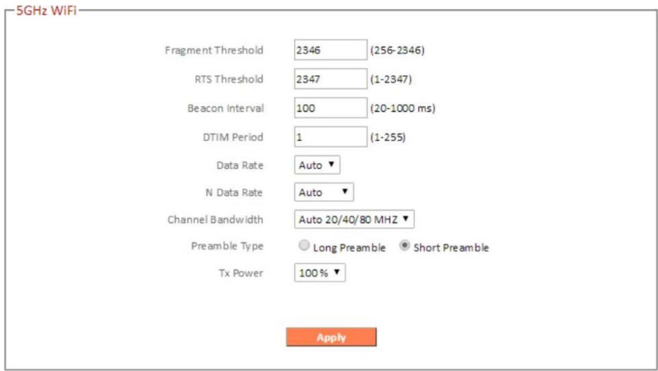
| =fragment Threshold | Set the Fragment threshold of the wireless radio. The default value is 2346. |
| RTS Threshold | Set the RTS threshold of the wireless radio. The default value is 2347. |
| Beacon Interval | Set the beacon interval of the wireless radio. The default value is 199. |
| DTI> Period | Set the DTIM period of wireless radio. The default value is 3. |
| Data Rate | Set the wireless data transfer rate. The default is set to Auto. |
| N Data Rate | Set the data rate of 892.11n. The default is set to Auto. |
| Channel Bandwidth | Select wireless channel width (bandwidth used by wireless signals from the device) – the recommended value is 29/49/89MHz. |
| Preamble Type | Set the wireless radio preamble type. The default value is “Short %reamble”. |
| Px-Power- | Set the power output of the wireless radio. You may not require 100% output power.-Setting a lower power output can enhance security since potentially malicious/unknown users in distant areas will not be able to access your signal. |
III-3-9-6. IG>P
IGM% is a communications protocol used to establish multicast group memberships. It allows for a more efficient use of resources and better performance for applications such as I%TV video streaming.

| IG>P Proxy | IGM% proxy erables intelligent multicast forwarding based on IGM% sncoping information. Select enable or disable. |

It is recommended to set "IGMP Proxy" to "Enable".
III-3-9-7. UPnP
Universal plug-and-play (U%n%) is a set of networking protocols which enables network devices to communicate and automatically establish working configurations with each other. Select “Enable” or “Disable”.

III-3-9-8. NAT
Enable or disable NAT (Network Address Translation) hardware acceleration for better network performance on fast connections.

III-3-104 Toolbox

Various administrative functions can be accessed from the “Administration” menu.
III-3-10-14 Time Zone
Setup time zone for your RA21S.

| Set Time Zone | Select the time zone of your country or region. |
| Time Server Address | The travel router supports NT% (Network Time %rotocol) for automatic time and date setup. Input the host name of the 1% server manually. |
| Daylight Saving | If your country/region uses daylight saving time, please check the “Enable” box, and select the start and end date. |
III-3-10-24 Password
You can change the password used to login to the browser-based configuration interface here. It is advised to do so for security purposes.

Please make a note of the new password. In the event that you forget the password and are unable to login to the browser based configuration interface, see I-5. Reset to factory default settings for how to reset the device.
Password
Current Password
New Password
Confirmed Password

Apply
| Current Password | Enter your current password. |
| New Password | Enter your new password. |
| Confirmed Password | Confirm your new password. |
III-3-10-34 Remote
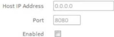
Check "Enable" to enable the remote access feature and then enter the appropriate values.
Remote Access
Save Settings
| Host IP Address | Specify the 1% address which is allowed remote access. |
| Port | Specify a port number (0–65535) used for remote access. |
III-3-10-4. Backup/Restore
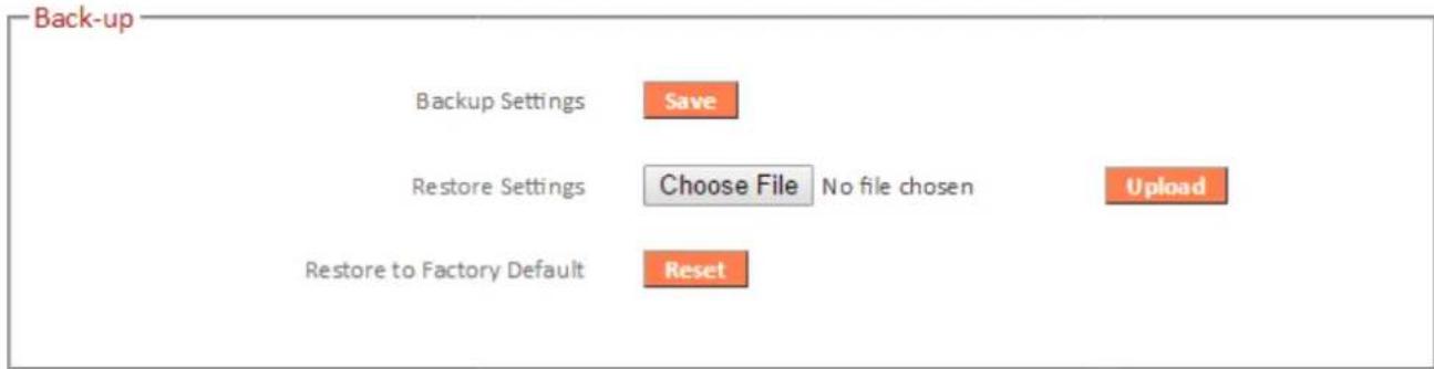
| Backup Settings | Click “Save” to save the current settings on your computer as config.bin file. |
| Restore Settings | Click “Browse” to find a previously saved config.bin file and then click “Upload” to replace your current settings. |
| Restore to=actory Default | Click “Reset” to restore settings to the factory default. A pop-up window will appear and ask you to confirm and enter your log in details.Enter your username and password and click “Ok”. See below for more information. |
III-3-10-5. =irmware
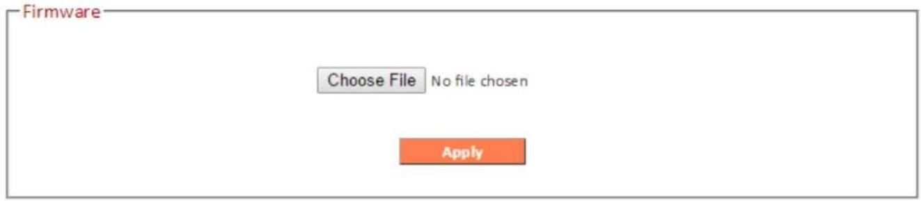
The firmware page allows you to upgrade the system firmware to a more recent version. You can download the latest firmware from the Edimax website and upgrade manually using the Choose =ile button. After the upgrade, the system will restart.

80 not switch off or disconnect the device during a firmware upgrade, as this could damage the device. It is recommended that you use a wired Ethernet connection for a firmware upgrade and that you backup your existing firmware before upgrading.
III-3-10-6. Restart
In the event that the router malfunctions or is not responding, then it is recommended that you restart the device.
Restart
In the event that the system stops responding correctly or stops functioning, you can perform a system restart. Your settings will not be changed. To restart, click on the APPLY button below. You will be asked to confirm your decision. The restart will be complete when the Internet LED light stops blinking.
Apply
III-3-10-7. Log
You can view the system log here.
Log
![2016/08/04 16:06:20 [SYSTEM]: [S3]: [admin]: WLAN[5G], Best channel selection st; 2016/08/04 16:06:07 [SYSTEM]: [S3]: [admin]: WLAN[2.4G], Skip Best channel selec 2016/08/04 15:36:42 [SYSTEM]: [S3]: [admin]: DHCP Server, Sending ACK of 192.16& 2016/08/04 15:36:42 [SYSTEM]: [S3]: [admin]: DHCP Server…](/content/2026/05/830652/images/273d27daf5179c2c3946c06f5f360fdf6b586c470ab48321784b0c5e48cefc42.jpg)
Save
clear
Refresh
| Save | Click “Save” to save the log on your computer as .txt file. |
| Clear | Click “Clear” to clear/erase the existing log. |
| Refresh | Click “Refresh” to refresh the log and update any activity. |
III-3-10-8. Active DHCP Client
Information about active DHC% clients is shown in the table, which displays the DHC% server assigned 1% address, MAC address and time expired for each computer or device on the local network.
Your device's DHC% server can be configured to assign static (fixed) 1% addresses to specified network devices, identified by their unique MAC address.

| Enable Static DHCP IP | Enable/disable static DHC% leases. This must be enabled in order to assign any network device a static 1% address. |
| IP Address | Assign a fixed 1% address for the specified network device here. |
| >AC Address | Enter the specified network device's MAC address here. |
| Add | Add the information to the “Static DHC% +eases Table”. |
| Clear | Clear the MAC address and 1% address fields. |
Delete Selected / Delete All Delete selected or all entries from the table.
| IP Address | Hostname | MAC Address | Expiration Time |
| 192.168.2.100 | Chromecast | A4:77:33:1E:0C:47 | Forever |
| 192.168.2.101 | 74:DA:38:8F:F5:02 | Forever | |
| 192.168.2.103 | android-f2a31148b00 | F8:A9:D0:0B:7D:A8 | Forever |
| 192.168.2.104 | android-3f038872981 | BC:EE:7B:4B:FA:3A | Forever |
| 192.168.2.105 | YotaPhone-fbe147d3d | 28:C6:71:02:AB:85 | Forever |
| 192.168.2.106 | E4:CE:8F:2 F:06:B8 | 89 days 13:39:52 |
Displays sent and received packet network statistics.
| 2.4GHz Wireless | Sent Packets | 36553 |
| Received Packets | 27058 | |
| 5GHz Wireless | Sent Packets | 2924 |
| Received Packets | 756 | |
| Ethernet LAN | Sent Packets | 3225 |
| Received Packets | 0 | |
| Ethernet WAN | Sent Packets | 25951 |
| Received Packets | 34267 |
IV-1. Configuring your IP address
For first time access to the UR+ http://edimax.setup?please ensure your computer is set to use a dynamic I% address. This means your computer can obtain an I% address automatically from a DHC% server. You can check if your computer is set to use a dynamic I% address by followingIV-1-1. How to check that your computer uses a dynamic IP address.
Static IP users can also temporarily modify your computer's I% address to be in the same I% address suk net e.g.192.168.2.x (x = 3 - 254) as the RA21S in order to access http://edimax.setup.

The RA21S's default IP address is 192.168.2.1.
The procedure for modifying your 1% address varies across different operating systems; please follow the guide appropriate for your operating system in IV-1-2. How to modify the IP address of your computer.

Static IP users please make a note of your static IP before you change it.
You can assign a new 1% address to the device which is within the subnet of your network during setup or using the browser based configuration interface (refer to III-3-4. LAN). Then you can access the UR+ http://edimax.setupzin future without modifying your 1% address

Please remember to change your IP address back to its original value after the device is properly configured.
IV-1-14 How to check that your computer uses a dynamic IP address %lease follow the instructions appropriate for your operating system.
IV-1-1-14 Windows XP
14 Click the "Start" button (it should be located in the lower-left corner of your computer), then click "Control %anel". Double-click the "Network and Internet Connections" icon, click "Network Connections", and then double-click "+ocal Area Connection". The "+ocal Area Connection Status" window will then appear, click "%properties".

24 "Obtain an 1% address automatically" and "Obtain DNS server address automatically" should be selected.

IV-1-1-24 Windows Vista
14 Click the “Start” button (it should be located in the lower-left corner of your computer), then click “Control Panel”. Click “View Network Status and Tasks”, then click “Manage Network Connections”. Right-click “Local Area Network”, then select “Properties”. The “Local Area Connection Properties” window will then appear, select “Internet Protocol Version 4 (TCP / IPv4)”, and then click “Properties”.

24 Select “Obtain an IP address automatically” and “Obtain DNS server address automatically” should be selected.

IV-1-1-3. Windows 7
- Click the "Start" button (it should be located in the lower-left corner of your computer), then click "Control %anel".
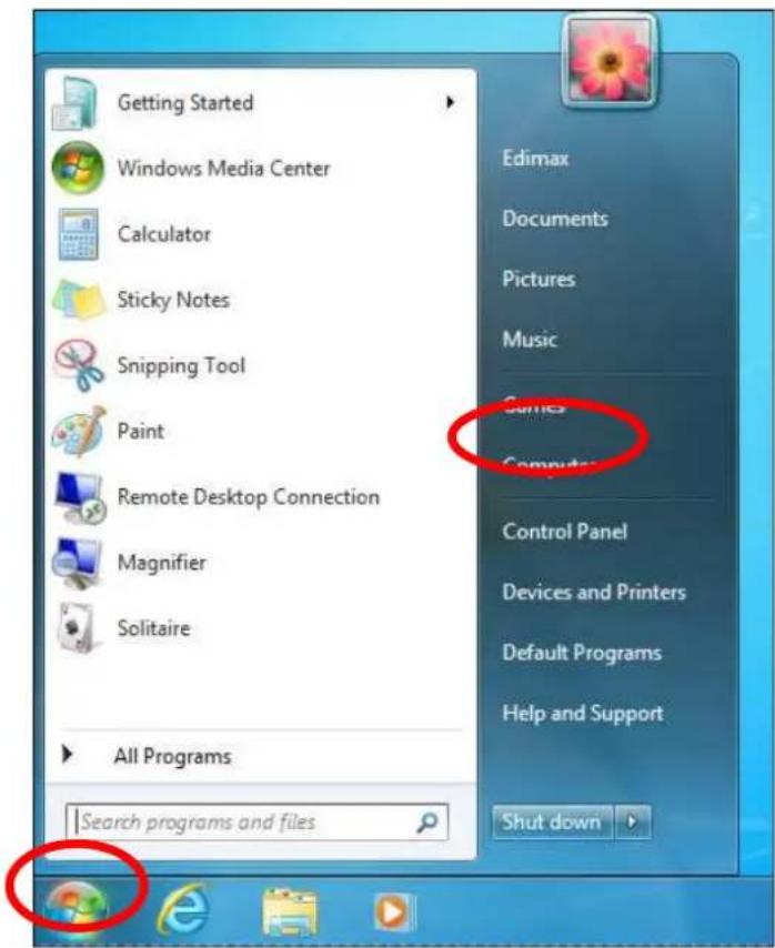
- Under "Network and Internet" click "View network status and tasks".

- Click "+ocal Area Connection".

4. Click "%properties".

5. Select "Internet %rotocol Version 4 (TC%7I%v4) and then click "%roperties".

- Select "Obtain an 1% address automatically" and "Obtain DNS server address automatically" should be selected.
IV-1-1-4. Windows 8
- From the Windows 8 Start screen, you need to switch to desktop mode. Move your cursor to the bottom left of the screen and click.

- In desktop mode, click the File Explorer icon in the bottom left of the screen, as shown below.

3. Right click "Network" and then select "%properties".

5. In the window that opens, select "Change adapter settings" from the left side.

- Choose your connection and right click, then select "%properties".
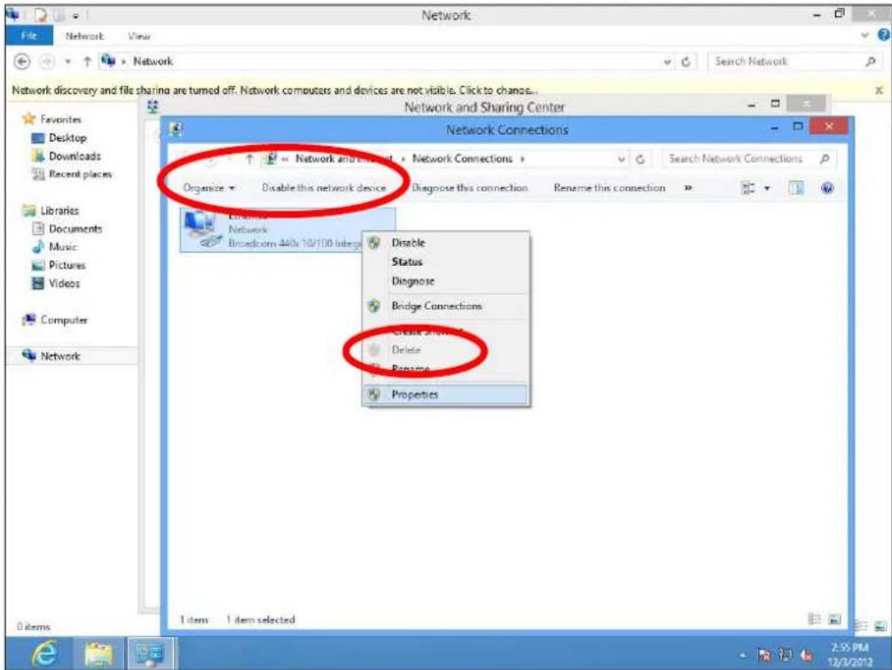
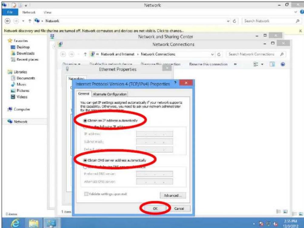
- Select "Internet %rotocol Version 4 (TC%/I%v4) and then click "%properties".

- Select "Obtain an 1% address automatically" and "Obtain DNS server address automatically" should be selected.
IV-1-1-5. >ac OS
- Have your Macintosh computer operate as usual, and click on "System %references".

- In System %references, click on "Network".

- Click on "Wi-Fi" in the left panel and then click "Advanced" in the lower right corner.
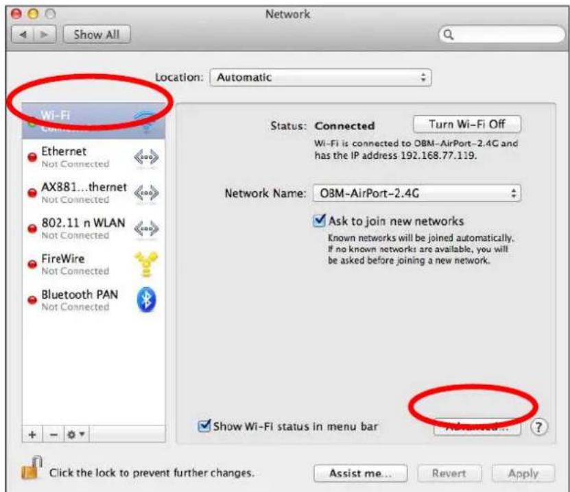
- Select "TC%/I%" from the top menu and "Using DHC%" in the drop down menu labeled "Configure I%v4" should be selected.

IV-1-2. How to modify the IP address of your computer
%lease follow the instructions appropriate for your operating system. In the following examples we use the I% address192.168.2.10 though you can use any I% address in the range192.168.2.x (x = 3 - 254) in order to access iQ Setup7browser based configuration interface.

Please make a note of your static IP before you change it.
IV-1-2-1. Windows XP
- Click the “Start” button (it should be located in the lower-left corner of your computer), then click “Control %anel”. Double-click the “Network and Internet Connections” icon, click “Network Connections”, and then double-click “+ocal Area Connection”. The “+ocal Area Connection Status” window will then appear, click “%properties”
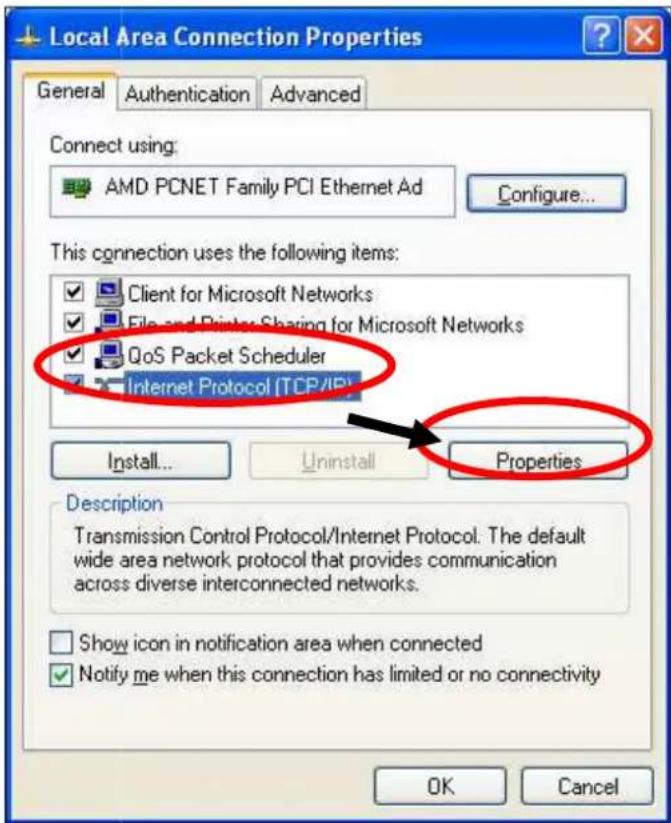
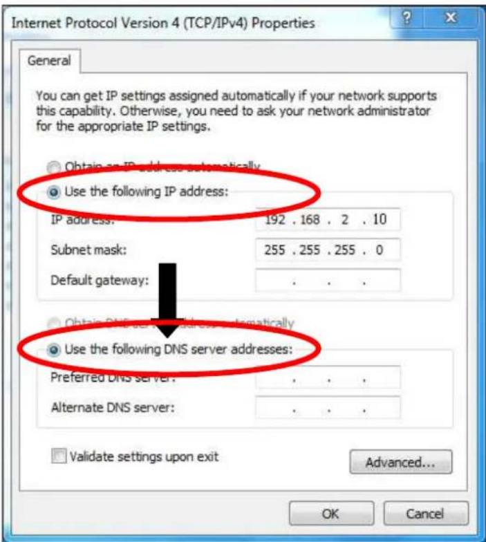
- Select "Use the following 1% address" and "Use the following DNS server addresses", then input the following values:

Your existing static IP address will be displayed in the "IP address" field before you replace it. Please make a note of this IP address, subnet mask, default gateway and 8NS server addresses.
'P-address: 192.168.2.10
Subnet->ask : 255.255.255.0
Preferred-ONS-Server: 192.168.2.1
Click 'OK' when finished.
IV-1-2-24 Windows Vista
14 Click the "Start" button (it should be located in the lower-left corner of your computer), then click "Control %anel". Click "View Network Status and Tasks", then click "Manage Network Connections". Right-click "+ocal Area Network", then select "%properties". The "+ocal Area Connection %properties" window will then appear, select "Internet %rotocol Version 4 (TC% / I%v4)" and then click "%properties"

24 Select "Use the following 1% address" and "Use the following DNS server addresses", then input the following values:
Your existing static IP address will be displayed in the "IP address" field before you replace it. Please make a note of this IP address, subnet mask, default gateway and 8NS server addresses.
IP address: 192.168.2.10 Subnet >ask : 255.255.255.0 Preferred DNS Server: 192.168.2.1
Click 'OK' when finished.
IV-1-2-3. Windows 7
- Click the "Start" button (it should be located in the lower-left corner of your computer), then click "Control %anel".

- Under "Network and Internet" click "View network status and tasks".

3. Click "+ocal Area Connection".

5. Click "%properties".
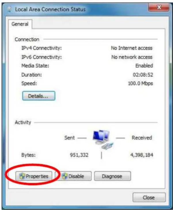
- Select "Internet %rotocol Version 4 (TC%/I%v) and then click "%properties"

- Select "Use the following 1% address" and "Use the following DNS server addresses", then input the following values:

Your existing static IP address will be displayed in the "IP address" field before you replace it. Please make a note of this IP address, subnet mask, default gateway and 8 NS server addresses.
IP address: 192.168.2.10
Subnet >ask : 255.255.255.0
Preferred DNS Server: 192.168.2.1
Click 'OK' when finished.
IV-1-2-4. Windows 8
- From the Windows 8 Start screen, you need to switch to desktop mode. Move your cursor to the bottom left of the screen and click.
![Start FAE-PC Mail Calendar Internet Explorer Stone 15 People Photos Maps SkyDrive Rio de Janeiro, Brazil Messaging NASDAQ 2386.99 ⬆ 0.08% [ 9.50] 02/4/2012 5:15 PM EST ESPN - Ilet Esterma takes Arkansas job Desktop Weather 34° London Mostly Cloudy 39°/28" Mars send: NASA to launch another river Game…](/content/2026/05/830652/images/614913aec341c3a4a49dcc6258aa1480592b3f0895d87e29332e521fc68975c6.jpg)
- In desktop mode, click the File Explorer icon in the bottom left of the screen, as shown below.
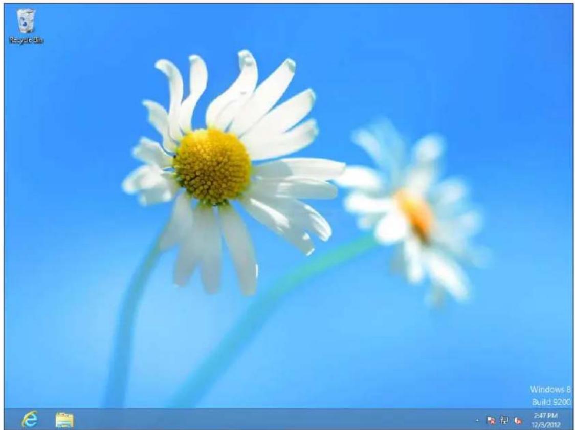
3. Right click "Network" and then select "%properties".

5. In the window that opens, select "Change adapter settings" from the left side.

- Choose your connection and right click, then select "%properties".

6. Select "Internet %rotocol Version 4 (TC%/I%v) and then click "%properties"

7. Select "Use the following 1% address" and "Use the following DNS server addresses", then input the following values:

Your existing static IP address will be displayed in the "IP address" field before you replace it. Please make a note of this IP address, subnet mask, default gateway and 8NS server addresses.
IP address: 192.168.2.10
Subnet >ask : 255.255.255.0
Preferred DNS Server: 192.168.2.1
Click 'OK' when finished.
IV-1-2-5. >ac
- Have your Macintosh computer operate as usual, and click on "System %references"
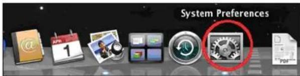
- In System %references, click on "Network".

- Click on "Wi-Fi" in the left panel and then click "Advanced" in the lower right corner.

- Select "TC%71%" from the top menu and select "Manually" from the drop down menu labeled "Configure I%v4", then click "OK".


Your existing static IP address will be displayed in the "IP address" field before you replace it. Please make a note of this IP address, subnet mask, default gateway and 8NS server addresses.
- In the "I%v4 Address" and "Subnet Mask" fielcenter I% address 192.168.2.10 and subnet mask 255.255.255.0. Click on "OK".

6. Click "Apply" to save the changes.

IV-1-3. How to =ind Your Network Security Key
To find your network security key, please follow the instructions appropriate for your operating system.

If you are using Windows XP or earlier, please contact your ISP or router manufacturer to find your network security key.
IV-1-3-1. Windows 7 & Vista
- Open "Control %anel" and click on "Network and Internet" in the top menu.

- Click on "View network status and tasks" which is under the heading "Network and Sharing Center".

- Click on "Manage wireless networks" in the left menu.

- You should see the profile of your Wi-Fi network in the list. Right click on your Wi-Fi network and then click on “%properties”.

- Click on the "Security" tab, and then check the box labeled "Show characters". This will show your network security key. Click the "Cancel" button to close the window.

IV-1-3-24 >ac
14 Open a new Finder window, and select "Applications" from the menu on the left side. Open the folder labeled "Utilities" and then open the application "Keychain Access".

24 Select "% passwords" from the sub-menu labeled "Category" on the left side, as shown below. Then search the list in the main panel for the SSID of your network. In this example, the SSID is "EdimaxWireless" – though your SSID will be unique to your network.

34 Double click the SSID of your network and you will see the following window.

- Check the box labeled "Show password" and you will be asked to enter your administrative password, which you use to log into your Mac. Enter your password and click "Allow".

Your network security password will now be displayed in the field next to the box labeled “Show password”. In the example below, the network security password is “edimax1234”. %lease make a note of your network security password.

IV-1-4. How to =ind Your Router's IP Address
To find your router's 1% address, please follow the instructions appropriate for your operating system.
IV-1-4-1. Windows XP, Vista & 7
- Go to "Start", select "Run" and type "cmd", then press Enter or click "OK".

24 A new window will open, type "ipconfig" and press Enter.
![Microsoft Windows [Version 6.0.6002] Copyright (c) 2006 Microsoft Corporation. All rights reserved. C:\Users\AlanChiu>ipconfig](/content/2026/05/830652/images/c2d103b7ee6b73784bf97b29781cd3d4fd93df2602722e8f75bbf5e11f0d443b.jpg)
34 Your router's 1% address will be displayed next to "Default Gateway".

IV-1-4-2. Windows 8
- From the Windows 8 Start screen, move your cursor to the top right corner of the screen to display the Charms bar.
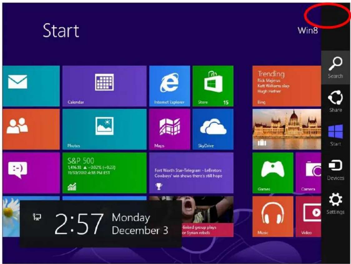
- Click "Search" and enter "cmd" into the search bar. Click the "Command %rompt" app which be displayed on the left side.

34 A new window will open, type "ipconfig" and press Enter.
![Microsoft Windows [Version 6.2.92001] (c) 2012 Microsoft Corporation. All rights reserved. C:\Users\Win8\ipconfig](/content/2026/05/830652/images/00f3dd0e8d54a7170d57a7f4842c2a5d4666bc81bcf258df35ac8c5bcb324acb.jpg)
- Your router's 1% address will be displayed next to "Default Gateway".

IV-1-5-3. >ac
- +aunch "System %references" and click on "Network".
- If you are using an Ethernet cable to connect to your network, your router's 1% address will be displayed next to "Router".

- If you are using Wi-Fi, click "Wi-Fi" in the left panel, and then "Advanced" in the bottom right corner.
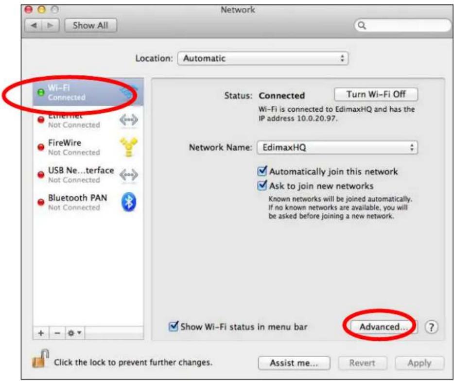
- Click the "TC%71%" tab and your router's 1% address will be displayed next to "Router".

IV-24 Connecting to a Wi-=i network
For help connecting to your device's Edimax.Setup SSID for initial setup, or to connect to your device's new Wi-Fi network (SSID) after setup is complete, follow the guide below:

Below is an example of how to connect using Windows Vista – the process may vary slightly for other versions of Windows.
14 Click the network icon (☐, or) in the system tray and select "Connect to a network".

24 Search for the SSID of your RA21S and then click "Connect". If you set a password for your network, you will then be prompted to enter it.

34 After correctly entering your password, you will be successfully connected to the RA21S's wireless network.

IV. -AQs
1. How do I setup a VPN server?(router mode only)
a. A V%N server can be used for remote access to your network as well as for additional security & privacy. +ogin to http://edimax.setup and go to Internet → VPN Server to setup the server. A V%N client such as OpenV%N is required on your network device to access the V%N remotely.

2. I can't access the Internet.
a. Ensure that all cables are connected properly. Try a different Ethernet cable.
b. Check if you can access the web based configuration interface. If not, please ensure your computer is set to use a dynamic 1% address.
c. +ogin to the web based configuration interface and go to Internet > IPv4 Settings and check that the login method/connection type is correct. If you are unsure which internet connection type you have, please contact your Internet Service %rovider (IS%).
d. Connect your computer directly to your modem and check if you can access the internet. If you can't, please contact your Internet service provider for assistance.
3. I can't open the web based configuration interface.
a. %lease ensure your computer is set to use a static I% address. (for example: 192.168.2.10) Now types in the A%’s I% address 192.168.2.1 into your browser to enter the configuration Interface.
4. How do I reset my device to factory default settings?
a. To reset the device back to its factory default settings, press and hold the W%S/Reset button for over 10 seconds, until the Internet +ED begins to flash. %lease wait a few minutes for the product to restart. When the device restarts, all settings will be reset. Default settings are displayed on the product label on the back of the device.
| Router Login Enter this UR+ in a web browser to run iQ Setup or configure advanced settings. You must be connected to the device by Wi-Fi or Ethernet cable. | |
| Username&Password | This is the default username and password to access the browser based configuration interface when you go to the “Router +ogin” UR+ (above). |
| Wi-=i Network Name | This is the default Wi-Fi network name for the device. Search for this name (SSID) and connect to it in order to access the “Router +ogin” UR+ (above). |
| >)C A MAC address is unique to every device and is used for identification within a network. Your device’s unique MAC addresses are displayed here. | |
| PIN CO0# This is your device’s %IN code for Wi-Fi %protected Setup (W%S,’ for each wireless frequency. | |
5. I forgot my password.
a. Reset the router to its factory default settings and use the default username admin and default password 1234. Default settings are displayed on the product label on the back of the device, as shown above.
6. Do the blue WAN port and yellow LAN ports work the same when the device is in different modes?
No, the WAN and +AN ports have slightly different functions depending on the operating mode of the device.
a. In Wi--i router mode, the WAN port is for a direct connection to your xDS+ modem. The LAN ports are for wired network clients.
b. In access point mode, the WAN port is not functional. Connect your existing router to the device's LAN port, and the other LAN ports can connect wired network clients.
V. Glossary
Default Gateway 9Wireless bridge): Every non-access point 1% device needs to configure a default gateway's 1% address. When the device sends out an 1% packet, if the destination is not on the same network, the device has to send the packet to its default gateway, which will then send it out towards the destination.
OHCP: Dynamic Host Configuration %rotocol. This protocol automatically gives every computer on your home network an 1% address.
ONS Server IP Address: DNS stands for Domain Name System, which allows Internet servers to have a domain name (such as www.Broadbandaccess point.com) and one or more I% addresses (such as 74.125.128.104). A DNS server keeps a database of Internet servers and their respective domain names and I% addresses, so that when a domain name is requested (as in typing "Broadbandaccess point.com" into your Internet browser), the user is sent to the proper I% address. The DNS server I% address used by the computers on your home network is the location of the DNS server your IS% has assigned to you.
0SL >odem: DS+ stands for Digital Subscriber +ine. A DS+ modem uses your existing phone lines to transmit data at high speeds.
thernet: A standard for computer networks. Ethernet networks are connected by special cables and hubs, and move data around at up to 10/100 million bits per second (Mbps).
IP Address and Network 9Subnet) >ask: I% stands for Internet %rotocol. An I% address consists of a series of four numbers separated by periods, that identifies a single, unique Internet computer host in an I% network. Example: 192.168.2.1. It consists of 2 portions: the I% network address, and the host identifier.
The 1% address is a 32-bit binary pattern, which can be represented as four cascaded decimal numbers separated by “.”: aaa.aaa.aaa.aaa, where each “aaa” can be anything from 000 to 255, or as four cascaded binary numbers separated by “.”: bbbbbbbb.bbbbbbbb.bbbbbbbb.bbbbbbbb, where each “b” can either be 0 or 1.
A network mask is also a 32-bit binary pattern, and consists of consecutive leading 1's followed by consecutive trailing 9's, such as 11111111.11111111.11111111.99999999. Therefore sometimes a network mask can also be described simply as "x" number of leading 1's. When both are represented side by side in their binary forms, all bits in the I% address that correspond to 1's in the network mask become part of the I% network address, and the remaining bits correspond to the host ID.
For example, if the I% address for a device is, in its binary form, 11911991.19119999.19919999.99999111, and if its network mask is, 11111111.11111111.11119999.99999999 It means the device's network address is 11911991.19119999.19919999.99999999, and its host ID is, 99999999.99999999.99999999.99999111. This is a convenient and efficient method for access points to route I% packets to their destination.
'SP--ateway-)ddress:-(see IS% for definition). The IS% Gateway Address is an 1% address for the Internet access point located at the IS%'s office.
'SP:-Internet Service %rovider. An IS% is a business that provides connectivity to the Internet for individuals and other businesses or organizations.
L)N:-+ocal Area Network. A +AN is a group of computers and devices connected together in a relatively small area (such as a house or an office). Your home network is considered a +AN.
)C-)ddress:-MAC stands for Media Access Control. A MAC address is the hardware address of a device connected to a network. The MAC address is a unique identifier for a device with an Ethernet interface. It is comprised of two parts: 3 bytes of data that corresponds to the Manufacturer ID (unique for each manufacturer), plus 3 bytes that are often used as the product's serial number.
N)T:-Network Address Translation. This process allows all of the computers on your home network to use one 1% address. Using the broadband access point's NAT capability, you can access the Internet from any computer on your home network without having to purchase more 1% addresses from your IS%.
Port:-Network Clients (+AN %C) uses port numbers to distinguish one network application/protocol over another. Below is a list of common applications and protocol/port numbers:
| Application | %rotoco | %ort Number |
| Telnet | TC% | 23 |
| FT% | TC% | 21 |
| SMT% | TC% | 25 |
| %O% | TC% | 119 |
| H.323 | TC% | 1729 |
| SNM% | UC% | 161 |
| SNM% Tra# | UD% | 162 |
| HTT% | TC% | 89 |
| %%T' | TC% | 1723 |
| %C Anywhere | TC% | 5631 |
| %C Anywhere | UD% | 5632 |
)ccess-point:-A access point is an intelligent network device that forwards packets between different networks based on network layer address information such as 1% addresses.
Subnet->ask:-A subnet mask, which may be a part of the TC%/I% information provided by your IS%, is a set of four numbers (e.g. 255.255.255.9) configured like an I% address. It is used to create I% address numbers used only within a particular network (as opposed to valid I% address numbers recognized by the Internet, which must be assigned by InterNIC).
TCP&IP,-UOP:-Transmission Control %rotocol/Internet %rotocol (TC%/I%) and User Datagram %rotocol (UD%). TC%/I% is the standard protocol for data transmission over the Internet. Both TC% and UD% are transport layer protocol. TC% performs proper error detection and error recovery, and thus is reliable. UD% on the other hand is not reliable. They both run on top of the I% (Internet %rotocol), a network layer protocol.
W)N:-Wide Area Network. A network that connects computers located in geographically separate areas (e.g. different buildings, cities, countries). The Internet is a wide area network.
Web-based management Graphical User Interface 9GUI): Many devices support a graphical user interface that is based on the web browser. This means the user can use the familiar Netscape or Microsoft Internet Explorer to Control7configure or monitor the device being managed.
СçРйâ'—:P-
Copyright © Edimax Technology Co., +td. all rights reserved. No part of this publication may be reproduced, transmitted, transcribed, stored in a retrieval system, or translated into any language or computer language, in any form or by any means, electronic, mechanical, magnetic, optical, chemical, manual or otherwise, without the prior written permission from Edimax Technology Co., +td.
Edimax Technology Co., +td. makes no representations or warranties, either expressed or implied, with respect to the contents hereof and specifically disclaims any warranties, merchantability, or fitness for any particular purpose. Any software described in this manual is sold or licensed as is. Should the programs prove defective following their purchase, the buyer (and not this company, its distributor, or its dealer) assumes the entire cost of all necessary servicing, repair, and any incidental or consequential damages resulting from any defect in the software. Edimax Technology Co., +td. reserves the right to revise this publication and to make changes from time to time in the contents hereof without the obligation to notify any person of such revision or changes.
The product you have purchased and the setup screen may appear slightly different from those shown in this QIG. The software and specifications are subject to change without notice. %lease visit our website www.edimax.com for updates. All brand and product names mentioned in this manual are trademarks and7or registered trademarks of their respective holders.
VI. Federal 90mmunication 90mission Interference Statement
This equipment has been tested and found to comply with the limits for a Class B digital device, pursuant to %art 15 of FCC Rules. These limits are designed to provide reasonable protection against harmful interference in a residential installation. This equipment generates, uses, and can radiate radio frequency energy and, if not installed and used in accordance with the instructions, may cause harmful interference to radio communications. However, there is no guarantee that interference will not occur in a particular installation. If this equipment does cause harmful interference to radio or television reception, which can be determined by turning the equipment off and on, the user is encouraged to try to correct the interference by one or more of the following measures:
- Reorient or relocate the receiving antenna.
- Increase the separation between the equipment and receiver.
- Connect the equipment into an outlet on a circuit different from that to which the receiver is connected.
- Consult the dealer or an experienced radio technician for help.
=CC Caution
This device and its antenna must not be co-located or operating in conjunction with any other antenna or transmitter. This device complies with %art 15 of the FCC Rules. Operation is subject to the following two conditions: (1) this device may not cause harmful interference, and (2) this device must accept any interference received, including interference that may cause undesired operation. Any changes or modifications not expressly approved by the party responsible for compliance could void the authority to operate equipment.
=ederal Communications Commission 9=CC) Radiation #xposure Statement
This equipment complies with FCC radiation exposure set forth for an uncontrolled environment. In order to avoid the possibility of exceeding the FCC radio frequency exposure limits, human proximity to the antenna shall not be less than 2.5cm (1 inch) during normal operation.
=ederal Communications Commission 9=CC) R= #xposure Requirements
This EUT is compliance with SAR for general population/uncontrolled exposure limits in ANSI/IEEE C95.1-1999 and had been tested in accordance with the measurement methods and procedures specified in OET Bulletin 65 Supplement C. The equipment version marketed in US is restricted to usage of the channels 1-11 only. This equipment is restricted to indoor use when operated in the 5.15 to 5.25 GHz frequency range.
VII. R&TTE 9ompliance Statement
This equipment complies with all the requirements of DIRECTIVE 1999/5/EC OF THE EURO%EAN %AR+IAMENT AND THE COUNCI+ of March 9, 1999 on radio equipment and telecommunication terminal equipment and the mutual recognition of their conformity (R&TTE). The R&TTE Directive repeals and replaces in the directive 98/13/EEC (Telecommunications Terminal Equipment and Satellite Earth Station Equipment) As of April 8, 2000.
Safety
This equipment is designed with the utmost care for the safety of those who install and use it. However, special attention must be paid to the dangers of electric shock and static electricity when working with electrical equipment. All guidelines of this and of the computer manufacture must therefore be allowed at all times to ensure the safe use of the equipment.
#U Countries Intended for Use
The ETSI version of this device is intended for home and office use in Austria, Belgium, Bulgaria, Cyprus, Czech, Denmark, Estonia, Finland, France, Germany, Greece, Hungary, Ireland, Italy, +atvia, +ithuania, +uxembourg, Malta, Netherlands, %oland, %ortugal, Romania, Slovakia, Slovenia, Spain, Sweden, Turkey, and United Kingdom. The ETSI
version of this device is also authorized for use in EFTA member states: Iceland, +iechtenstein, Norway, and Switzerland.
y-Countries-Not-'ntended-for-yse-
None
#U Declaration of Conformity
nglish: This equipment is in compliance with the essential requirements and other relevant provisions of Directive 1999/5/EC, 2009/125/EC.
=rançais: Cet équipement est conforme aux exigences essentielles et autres dispositions de la directive 1999/5/CE, 2009/125/CE.
Čeština: Toto zařízení je v souladu se základními požadavky a ostatními příslušnými ustanoveními směrnic 1999/5/ES, 2009/125/ES.
Polski: Urządzenie jest zgodne z ogólnymi wymaganiami oraz szczególnymi warunkami określonymi Dyrektywą UE 1999/5/EC, 2009/125/EC.
Română: Acest echipament este în conformitate cu cerințele esențiale și alte prevederi relevante ale Directivei 1999/5/CE, 2009/125/CE.
Русский: Это оборудование соответствует основным требованиям и положениям Директивы 1999/5/EC, 2009/125/EC.
agyar: Ez a berendezés megfelel az alapvető követelményeknek és más vonatkozó irányelveknek (1999/5/EK, 2009/125/EC).
Türkçe: Bu cihaz 1999/5/EC, 2009/125/EC direktifleri zorunlu istekler ve diğer hükümlerle ile uyumludur.
Українська: Обладнання відповідає вимогам і умовам директиви 1999/5/EC, 2009/125/EC.
Slovenčina: Toto zariadenie splňa základné požiadavky a d’alšie príslušné ustanovenia smerníc 1999/5/ES, 2009/125/ES.
Deutsch: Dieses Gerät erfüllt die Voraussetzungen gemäß den Richtlinien 1999/5/EC, 2009/125/EC.
At the end of its serviceable life, this product should not be treated as household or general waste. It should be handed over to the applicable collection point for the recycling of electrical and electronic equipment, or returned to the supplier for disposal.
Declaration of Conformity
We, Edimax Technology Co., +td., declare under our sole responsibility, that the equipment described below complies with the requirements of the European R&TTE directives 1999/5/EC, directive 2011/65/EC (RoHS) and directive 2009/125/EC (Er%).
Equipment: Home Wi-=i Roaming Router/Access Point
odel No4: RA21S
The following European standards for essential requirements have been followed:
Directives 1999/5/EC
Spectrum : ETSI EN 300 328 V1.9.1 (2015-06); ETSI EN 301 893 V1.8.1 (2015-06)
EMC : EN 301 489-1 V1.9.2 (2011-09); EN 301 489-17 V2.2.1 (2012-09)
Safety (LVD) : IEC 60950-1:2005 ( 2nd Edition)+A1:2009+A2:2013 EN 60950-1:2006+A11:2009+A1:2010+A12:2011+A2:2013
Recommendation 99/519/EC
EMF : EN 62311: 2008
Directives 2006/95/EC
Safety (LVD) : IEC 60950-1:2005 ( 2nd Edition)+A1:2009+A2:2013 EN 60950-1:2006+A11:2009+A1:2010+A12:2011+A2:2013
Edimax Technology Co., +td. No. 3, Wu Chuan 3 rd Road, Wu-Ku Industrial %ark, New Taipei City, Taiwan

Date of Signature: Nov., 2016
Signature:

%rinted Name: Albert Chang
Title: Director Edimax Technology Co., +td.
ΣDIMAX
NETWORKING PEOPLE TOGETHER


- EDIMAX TECHNOLOGY EUROPE B.V
- EDIMAX COMPUTER COMPANY
- CONTENTS
- PRODUCT INFORMATION .... 1
- INSTALLATION 6
- II-3. WI= I ROAMING .... 17
- APPENDIX ......97
- AQS 138
- GLOSSARY 141
- EDERAL COMMUNICATION COMMISSION INTERFERENCE STATEMENT ...... 146
- R&TTE COMPLIANCE STATEMENT 146
- PRODUCT INFORMATION
- I-14 PACKAGE CONTENTS
- I-24 LED STATUS
- I-34 BACK PANEL
- I-5. SAFETY INFORMATION
- I-5. RESET TO =ACTORY DEFAULT SETTINGS
- INSTALLATION
- II-14 WI-=I ROUTER >ODE
- MANUAL CONFIGURATION IS ONLY RECOMMENDED FOR ADVANCED USERS
- EDIMAX
- CONGRATULATIONS
- II-24 ACCESS POINT >ODE
- II-3. WI-FI ROAMING
- TO SETUP OTHER EDI>AX WI-=I ROAMING RANGE EXTENDER, REFER TO THEIR INCLUDED DOCUMENTATION FOR INSTRUCTIONS 4
- BROWSER BASED CONFIGURATION INTERFACE
- III-14 LOGIN
- III-24 SAVE SETTINGS
- III-34 >AIN >ENU
- III-3-14 STATUS
- III-3-1-14 DEVICE
- III-3-1-2. IPV5
- III-3-1-3. IPV6
- IPV6 CONNECTION INFORMATION
- III-3-24 SETUP WIZARD
- SETUP WIZARD
- RESET TO DEFAULT
- III-3-3. INTERNET
- III-3-3-1. IPV5
- III-3-3-1-1. STATIC IP
- III-3-3-1-24 DYNAMIC IP
- III-3-3-1-34 PPPOE
- III-3-3-1-5. PPTP
- III-3-3-1-5. L2TP
- III-3-3-1-6. RUSSIA L2TP 9DUAL-ACCESS)
- III-3-3-1-7. DS-LITE
- III-3-3-2. IPV6
- 9CHECK WITH YOUR ISP FOR CORRECT IPV6 CONFIGURATION
- IPV6 CONNECTION TYPE
- III-3-3-2-1. STATIC IP
- 9HECK WITH YOUR ISP FOR CORRECT IPV6 CONFIGURATION
- III-3-3-2-24 PPPOE
- III-3-3-2-3. AUTO-CONFIGURATION
- III-3-3-2-4. 6RD
- III-3-3-2-5. LINK-LOCAL
- III-3-3-34 DDNS
- DDNS
- III-3-4. LAN
- LAN IP
- III-3-5. 2.4GHZ WIRELESS & 5GHZ WIRELESS
- III-3-5-1. BASIC
- )CCESS-POINT->ODE
- BASIC
- III-3-5-2. SECURITY
- III-3-5-2-2. WEP
- III-3-5-2-3. WPA PRE-SHARED KEY
- III-3-5-2-4. WPA RADIUS
- III-3-5-3. WPS
- WPS
- III-3-6. SCHEDULE
- 34 REMEMBER TO APPLY YOUR CHANGES AND MAKE SURE ENABLE IS CHECKED
- III-3-7. =IREWALL
- III-3-7-1. ACCESS
- ACCESS
- III-3-7-2. D>Z
- III-3-7-3. DOS
- III-3-8. QOS
- III-3-8-1. QOS
- III-3-9. ADVANCED
- III-3-9-1. STATIC ROUTING
- STATIC ROUTING
- III-3-9-2. PORT = FORWARDING
- III-3-9-4. 2.4GHZ WIRELESS
- 2.4GHZ WIFI
- III-3-9-5. 5GHZ WIRELESS
- III-3-9-6. IG>P
- III-3-9-7. UPNP
- III-3-9-8. NAT
- III-3-104 TOOLBOX
- III-3-10-14 TIME ZONE
- III-3-10-24 PASSWORD
- PASSWORD
- III-3-10-34 REMOTE
- III-3-10-4. BACKUP/RESTORE
- III-3-10-5. =IRMWARE
- III-3-10-6. RESTART
- RESTART
- III-3-10-7. LOG
- LOG
- III-3-10-8. ACTIVE DHCP CLIENT
- IV-1. CONFIGURING YOUR IP ADDRESS
- IV-1-1-14 WINDOWS XP
- IV-1-1-24 WINDOWS VISTA
- IV-1-1-3. WINDOWS 7
- CLICK "%PROPERTIES
- SELECT "INTERNET %ROTOCOL VERSION 4 (TC%7I%V4) AND THEN CLICK "%ROPERTIES
- IV-1-1-4. WINDOWS 8
- RIGHT CLICK "NETWORK" AND THEN SELECT "%PROPERTIES
- IN THE WINDOW THAT OPENS, SELECT "CHANGE ADAPTER SETTINGS" FROM THE LEFT SIDE
- IV-1-1-5. >AC OS
- IV-1-2. HOW TO MODIFY THE IP ADDRESS OF YOUR COMPUTER
- IV-1-2-1. WINDOWS XP
- IV-1-2-24 WINDOWS VISTA
- IV-1-2-3. WINDOWS 7
- CLICK "+OCAL AREA CONNECTION
- IV-1-2-4. WINDOWS 8
- SELECT "INTERNET %ROTOCOL VERSION 4 (TC%/I%V) AND THEN CLICK "%PROPERTIES
- SELECT "USE THE FOLLOWING 1% ADDRESS" AND "USE THE FOLLOWING DNS SERVER ADDRESSES", THEN INPUT THE FOLLOWING VALUES
- IV-1-2-5. >AC
- CLICK "APPLY" TO SAVE THE CHANGES
- IV-1-3. HOW TO =IND YOUR NETWORK SECURITY KEY
- IV-1-3-1. WINDOWS 7 & VISTA
- IV-1-3-24 >AC
- IV-1-4. HOW TO =IND YOUR ROUTER'S IP ADDRESS
- IV-1-4-1. WINDOWS XP, VISTA & 7
- IV-1-4-2. WINDOWS 8
- IV-1-5-3. >AC
- IV-24 CONNECTING TO A WI-=I NETWORK
- AQS
- HOW DO I SETUP A VPN SERVER?(ROUTER MODE ONLY)
- I CAN'T ACCESS THE INTERNET
- I CAN'T OPEN THE WEB BASED CONFIGURATION INTERFACE
- HOW DO I RESET MY DEVICE TO FACTORY DEFAULT SETTINGS
- I FORGOT MY PASSWORD
- DO THE BLUE WAN PORT AND YELLOW LAN PORTS WORK THE SAME WHEN THE DEVICE IS IN DIFFERENT MODES
- GLOSSARY
- THERNET: A STANDARD FOR COMPUTER NETWORKS. ETHERNET NETWORKS ARE CONNECTED BY SPECIAL CABLES AND HUBS, AND MOVE DATA AROUND AT UP TO 10/100 MILLION BITS PER SECOND (MBPS)
- СÇРЙÂ'—:P
- FEDERAL 90MMUNICATION 90MISSION INTERFERENCE STATEMENT
- CC CAUTION
- EDERAL COMMUNICATIONS COMMISSION 9=CC) RADIATION #XPOSURE STATEMENT
- EDERAL COMMUNICATIONS COMMISSION 9=CC) R= #XPOSURE REQUIREMENTS
- R&TTE 9OMPLIANCE STATEMENT
- SAFETY
- U COUNTRIES INTENDED FOR USE
- Y-COUNTRIES-NOT-'NTENDED-FOR-YSE
- U DECLARATION OF CONFORMITY
- NGLISH: THIS EQUIPMENT IS IN COMPLIANCE WITH THE ESSENTIAL REQUIREMENTS AND OTHER RELEVANT PROVISIONS OF DIRECTIVE 1999/5/EC, 2009/125/EC
- DECLARATION OF CONFORMITY
- DIRECTIVES 1999/5/EC
- RECOMMENDATION 99/519/EC
- DIRECTIVES 2006/95/EC
- ΣDIMAX
- NETWORKING PEOPLE TOGETHER
Brand : Edimax
Model : RA21S
Category : Access Point