
102P3 - Automatic watering Irritrol - Free user manual and instructions
Find the device manual for free 102P3 Irritrol in PDF.


| Product Type | Automatic irrigation valve (electric) |
| Brand | Irritrol |
| Model | 102P3 (100/100S Series) |
| Dimensions (1" model) | 6 3/4" H x 3 5/8" W |
| Dimensions (1 1/2" model) | 7 1/4" H x 3" W |
| Dimensions (2" model) | 9 1/2" H x 6 1/8" W |
| Dimensions (3" model) | 10 3/4" H x 6 1/8" W |
| Flow Range | 5 - 300 GPM |
| Operating Pressure | 20 - 220 PSI |
| Burst Pressure Rating | 450 - 500 PSI |
| Power Supply | 24 VAC solenoid (inrush 0.40-0.50 A, holding 0.20-0.30 A) |
| Flow Control | Manual flow control with adjustable zero flow |
| Manual Bleed | Internal (downstream) and external (atmosphere) bleed screws |
| Special Feature (100S) | Continuous scrubbing turbine for dirty water applications |
| Body Material | Glass-reinforced nylon, stainless steel, brass, EPDM rubber |
| Installation | Can be installed at any angle; use PTFE tape or sealant |
| Maintenance | Self-cleaning metering system; external bleed allows cleaning of metering rod |
| Safety | High pressure rating; use waterproof splice connectors |
| Spare Parts Availability | Solenoid, diaphragm, o-rings, metering rod (user serviceable) |
| Repairability | Top access for internal components; valve body plug and o-ring replaceable |
Frequently Asked Questions - 102P3 Irritrol
User questions about 102P3 Irritrol
0 question about this device. Answer the ones you know or ask your own.
Ask a new question about this device
Download the instructions for your Automatic watering in PDF format for free! Find your manual 102P3 - Irritrol and take your electronic device back in hand. On this page are published all the documents necessary for the use of your device. 102P3 by Irritrol.
USER MANUAL 102P3 Irritrol
100 / 100-S Series Valves
Installation Instruction
Introduction
100 Series Valve
Built on proven technologies and components, the Irritrol 100 Series valves are tough, have excellent performance, and are extremely reliable. A self-cleaning metering system and 220 PSI rating assures years of trouble-free performance.
100S Series "Scrubber" Valve
Constructed of heavy-duty, glass-reinforced nylon, high grade stainless steel, brass and EPDM rubber materials, the 100 Series scrubber valves resist clogging. The patent-pending continuous scrubbing mechanism actively fights dirt, algae and other particles from disrupting the functionality of the valve. The 100 Series scrubber valves are true dirty water irrigation valves, able to handle the harsh chemicals found in dirty water systems, such as chlorines, chloramines and water treated with ozones.
Installation Recommendations
- In commercial installations, it is advantageous to install the valves in a valve box. This enables the valve to be easily located, accessed, and maintained.
- Partially fill the bottom of the valve box with clean aggregate to facilitate drainage.
- Locate the valve box away from structures, hardscape features (such as sidewalks), and large planting locations.
- Locate the valve box in shrub beds and at right angles to structure locations.
- If valves are installed below grade without a valve box, access to the top of the valve should be provided by using a section of 4" PVC pipe and a valve cover installed directly over each valve.

natural_image
3D technical illustration of a mechanical valve component (no text or symbols visible)
natural_image
3D rendered mechanical valve component with no visible text or symbols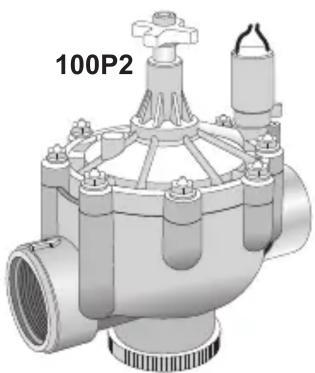
natural_image
3D rendering of a mechanical valve component with no visible text or symbols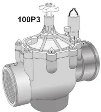
natural_image
3D rendering of a mechanical valve component with no visible text or symbolsFeatures
100 Series Valve
• 220 PSI maximum pressure rating
- Removable, self-cleaning metering system
- Precise pressure control with optional Omni-Reg® pressure regulator (field installed)
- Manual flow control: adjustable to zero flow
- Internal manual bleed screw: bleeds internally downstream
- External manual bleed screw: bleeds to atmosphere, allows cleaning of metering rod and provides maximum flushing
100S Series "Scrubber" Valve
- All the great features of the 100 Series valve.
- Continuous scrubbing turbine actively cleans the metering device for consistent valve operation in dirty water applications.
Installation Guidelines

Using pipe dope on valve connections can cause thread damage and failure of the valve body.
Use only PTFE tape or pipe thread sealant.
- Note the flow direction arrows on the bonnet or body and install accordingly.
- The valve can be installed at any angle without affecting operation.
-
The valve body plug and o-ring must be properly installed in the unused inlet.
-
Use direct-burial wire, utilizing different color codes for each station control wire and one color for the common wire to all valves.
- Waterproof wire splice connectors are absolutely essential for proper electric control system operation. Follow the installation instructions provided with the connectors for optimum waterproof splice protection.
- Leaving a wire expansion loop at each valve location on long-run wire lengths is recommended.
Specifications
Models:
100/100S Series electric
1", 1 ^1/2 ", 2", and 3"
Body Style:
Globe/Angle with female threads (all models)
BSP threads available
Dimensions:
1": 6 ^3/4 " H x 3 ^5/8 " W
1^1/2": 7^1/4" H × 3" W
2": 9 ^1/2 " H x 6 ^1/8 " W
3": 10 ^3/4 " H x 6 ^1/8 " W
Flow range: 5 - 300 GPM
Burst pressure safety rating:
450-500 PSI
Operating Pressure:
20-220 PSI maximum
Minimum pressure differential:
20 PSI
(between inlet and outlet)
Solenoid (standard): 24 VAC
Inrush: 0.40 amps, 11.50 VA; Max.
Inrush: 0.50 amps
Holding: 0.20 amps, 5.75 VA; Max.
Holding: 0.30 amps
Voltage Requirement (based on inlet
pressure):
22.5 V a.c. @ 220 PSI
21.1 V a.c. @ 200 PSI
20.2 V a.c. @ 175 PSI
19.1 V a.c. @ 150 PSI
18.2 V a.c. @ 125 PSI
16.1 V a.c. @ 75 PSI
16.0 V a.c. @ 50 PSI
Valve Operation
Flow Control
Flow control reduces the flow and pressure to valve outlet. By turning the control handle clockwise, the flow will be gradually reduced to zero.
Internal Manual Bleed Knob
The internal manual bleed system is used to manually operate the valve. Turning the internal bleed knob (located beneath the solenoid) counterclockwise allows water to bleed downstream from the diaphragm chamber. Internal

pressure is relieved from the top of the diaphragm, allowing the valve to open. Turning the bleed knob clockwise until tight shuts off the discharge enabling pressure to build within the diaphragm chamber, causing the valve to close.
External Manual Bleed Knob (flush mode)
The external manual bleed knob, located on top of the flow control handle, is used for system flushing. Turning this knob counterclockwise allows water in the diaphragm chamber to vent to atmosphere, creating maximum opening power and debris flushing action. This operation bypasses the regulator (if installed) and opens the valve fully, regardless of regulator setting. In addition, the metering rod (attached to the external bleed knob) can be easily removed for cleaning as necessary.
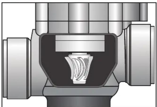
100S Scrubber Operation
Continuous scrubbing turbine actively cleans the metering device for consistent valve operation in dirty water applications.
natural_image
Cross-sectional diagram of a mechanical component with internal channels and housing (no text or symbols)Patented scrubber impeller
Lirritrol®
| Size | Conting. | 5 | 10 | 20 | 30 | 40 | 50 | 60 | 70 | 80 | 90 | 100 | 110 | 120 | 130 | 140 | 150 | 180 | 200 | 225 | 250 | 275 | 300 |
| 1"globe angle | 4.5globe angle | 2.6globe 4.3 | 5.1globe 2.5 | 9.0globe 2.5 | 14.0globe 9.1 | 13.5 | 5.8globe 0.9 | 1.0globe 0.9 | 1.4globe 1.3 | 2.7globe 2.3 | 4.0globe 3.5 | 5.8globe 4.9 | 7.9globe 6.6 | 10.2globe 9.0 | 11.2globe 11.2 | 13.5globe 13.5 | 16.6g | 19.8g | 16.1g | 19.8g | 16.6 | ||
| 2"globe angle | 3.5globe 2.8 | 4.5globe 3.8 | 5.4globe 4.5 | 6.7globe 5.5 | 8.0globe 6.3 | 9.3globe 7.6 | 11.0globe 10.3 | 13.7globe 13.1 | |||||||||||||||
| 3"globe angle |
GPM Flow by Size
100S „Scrubber „Series
| Size | Configy. | 5 | 10 | 20 | 30 | 40 | 50 | 60 | 70 | 80 | 90 | 100 | 110 | 120 | 130 | 140 | 150 | 180 | 200 | 225 | 250 | 275 | 300 |
| 1"globe angle | 6.3 | 4.2 | 3.2 | 4.1 | 7.2 | 10.9 | |||||||||||||||||
| 1.5" globe angle | 1.6 | 2.3 | 3.6 | 5.2 | 7.0 | 9.2 | 11.7 | 14.4 | 17.5 | 13.3 | |||||||||||||
| 2"globe angle | 2.1 | 1.2 | 2.7 | 3.3 | 4.0 | 4.8 | 5.6 | 6.5 | 7.5 | 8.05 | 5.1 | ||||||||||||
| 3"globe angle | 2.5 | 1.9 | 2.4 | 3.0 | 3.3 | 3.9 | 4.4 | 5.5 | 6.7 | 8.3 | 5.5 | 6.9 | 10.1 | 8.5 |
GPM Flow by Size
100 Series
For optimum performance when designing a system, be sure to calculate total friction loss to ensure sufficient downstream pressure. For optimum regulation performance, size regulating values toward the higher flow ranges.
Friction Loss Chart (US PSI)


- / 100-S Series Valves
- Installation Instruction
- Introduction
- Series Valve
- 100S Series "Scrubber" Valve
- Installation Recommendations
- Features
- Installation Guidelines
- Specifications
- Models:
- Body Style:
- Dimensions:
- Burst pressure safety rating:
- Operating Pressure:
- Minimum pressure differential:
- PSI
- (between inlet and outlet)
- Voltage Requirement (based on inlet
- pressure):
- Valve Operation
- Flow Control
- Internal Manual Bleed Knob
- External Manual Bleed Knob (flush mode)
- 100S Scrubber Operation
Brand : Irritrol
Model : 102P3
Category : Automatic watering