
HG3 - Uncategorized Tenda - Free user manual and instructions
Find the device manual for free HG3 Tenda in PDF.


| Product Type | N300 Wi-Fi xPON ONT (Optical Network Terminal) |
| Dimensions (approx.) | 150 x 100 x 30 mm (5.9 x 3.9 x 1.2 in) |
| Weight (approx.) | 200 g (7.0 oz) |
| Power Supply | 12V DC, 1A via included power adapter |
| Wi-Fi Standard | IEEE 802.11b/g/n, 2.4 GHz, up to 300 Mbps |
| Ports | 1x PON (SC/APC fiber), 1x Gigabit LAN (LAN1-GE), 1x 100M LAN (LAN2), 1x Power jack, 1x WPS/RST button |
| LED Indicators | PWR (green), PON (green), LOS (red), LAN (green), WLAN (green) |
| WAN Modes | Bridge mode, Router mode (PPPoE, DHCP, Static IP, 6rd) |
| Security | WPA/WPA2-PSK encryption, MAC/URL/IP/Port filtering, Access Control List (ACL) |
| Additional Features | Multiple SSID (up to 4), WPS, UPnP, DMZ, Port Forwarding, DDNS, IGMP/MLD Proxy, VLAN |
| Management | Web UI (192.168.1.1), TR-069 remote management, backup/restore configuration |
| Firmware Upgrade | Via web UI, download from tendacn.com |
| Environmental | Operating temperature: 0°C to 40°C (32°F to 104°F) |
| Maintenance | Keep clean, avoid dust; reset via web or button; firmware updates recommended |
| Safety | Use only supplied power adapter; keep away from water; avoid overheating |
| Spare Parts / Repairability | No user-serviceable parts; contact ISP or Tenda support for issues |
| General Info | FTTH device for fiber internet; default login admin/admin; label on bottom includes SSID, key, MAC, PON SN |
Frequently Asked Questions - HG3 Tenda
User questions about HG3 Tenda
0 question about this device. Answer the ones you know or ask your own.
Ask a new question about this device
Download the instructions for your Uncategorized in PDF format for free! Find your manual HG3 - Tenda and take your electronic device back in hand. On this page are published all the documents necessary for the use of your device. HG3 by Tenda.
USER MANUAL HG3 Tenda
natural_image
Orange background with white globe and laptop icon (no text or symbols)
natural_image
Two girls playing on a white wall with green shutters, one lying down and the other lying up (no text or symbols visible)N300 Wi-Fi xPON ONT User Guide
V1.0
Copyright Statement
© 2022 Shenzhen Tenda Technology Co., Ltd. All rights reserved.
Tenda is a registered trademark legally held by Shenzhen Tenda Technology Co., Ltd. Other brand and product names mentioned herein are trademarks or registered trademarks of their respective holders. Copyright of the whole product as integration, including its accessories and software, belongs to Shenzhen Tenda Technology Co., Ltd. No part of this publication can be reproduced, transmitted, transcribed, stored in a retrieval system, or translated into any language in any form or by any means without the prior written permission of Shenzhen Tenda Technology Co., Ltd.
Disclaimer
Pictures, images and product specifications herein are for references only. To improve internal design, operational function, and/or reliability, Tenda reserves the right to make changes to the products without obligation to notify any person or organization of such revisions or changes. Tenda does not assume any liability that may occur due to the use or application of the product described herein. Every effort has been made in the preparation of this document to ensure accuracy of the contents, but all statements, information and recommendations in this document do not constitute a warranty of any kind, express or implied.
Preface
Thank you for choosing Tenda!
This user guide walks you through all functions of the N300 Wi-Fi xPON ONT (HG3 used for illustration). All the screenshots herein, unless otherwise specified, are taken from HG3.

Web UI of different models may differ. The Web UI displayed shall prevail.
Conventions
The typographical elements that may be found in this document are defined as follows.
| Item | Presentation | Example |
| Cascading menus | > | System > Live Users |
| Parameter and value | Bold | Set User Name to Tom. |
| Variable | Italic | Format: XX:XX:XX:XX:XX:XX |
| UI control | Bold | On the Policy page, click the OK button. |
| Message | “” | The “Success” message appears. |
The symbols that may be found in this document are defined as follows.
| Symbol | Meaning |
 | This format is used to highlight information of importance or special interest. Ignoring this type of note may result in ineffective configuration, loss of data or damage to devices. |
 | This format is used to highlight a procedure that will save time or resources. |
For more documents
If you want to get more documents of the device, visit www.tendacn.com and search for the corresponding product model.
The related documents are listed as below.
| Document | Description |
| Data Sheet | It introduces the basic information of the device, including product overview, selling points, and specifications. |
| Quick Installation Guide | It introduces how to set up the device quickly for internet access, the descriptions of LED indicators, ports, and buttons, FAQ, statement information, and so on. |
| User Guide | It introduces how to set up more functions of the device for more requirements, including all functions on the web UI of the device. |
Technical Support
If you need more help, contact us by any of the following means. We will be glad to assist you as soon as possible.

Hotline
Global: (86) 755-27657180
(China Time Zone)
United States: 1-800-570-5892
(Toll Free: 7 x 24 hours)
Canada: 1-888-998-8966
(Toll Free: Mon - Fri 9 am - 6 pm PST)
Hong Kong: 00852-81931998

support@tenda.com.cn

Website
www.tendacn.com
Revision History
Tenda is constantly searching for ways to improve its products and documentation. The following table indicates any changes that might have been made since this guide was first published.
| Version | Date | Description |
| V1.0 | 2022-04-20 | Original publication. |
Contents
1 Get to know your device .... 1
1.1 Overview .... 1
1.2 Appearance .... 1
1.2.1 Indicators, ports, and buttons .... 1
1.2.2 Label 3
2 Web UI 4
2.1 Login 4
2.2 Logout....5
2.3 Web UI layout 6
2.4 Common buttons....7
3 Status 8
3.1 Device status 8
3.2 IPv6 status .... 10
3.3 PON status....11
4 LAN....12
5 WLAN....13
5.1 Basic settings.... 13
5.1.1 Overview 13
5.1.2 Customize the main Wi-Fi name 15
5.1.3 Enable multiple wireless networks .... 15
5.2 Advanced settings....17
5.2.1 Overview 17
5.2.2 Hide the main Wi-Fi name....18
5.3 Security....19
5.3.1 Overview 19
Contents
5.3.2 Customize the Wi-Fi password 19
5.4 Access control 21
5.4.1 Overview 21
5.4.2 Allow certain clients to access the Wi-Fi network 21
5.5 WPS....23
5.5.1 Overview 23
5.5.2 Connect to the Wi-Fi network using the WPS button 23
5.5.3 Connect to the Wi-Fi network using PBC on the web UI....25
5.5.4 Connect to the Wi-Fi network by entering PIN code of clients on the ONT ..... 27
5.5.5 Connect to the Wi-Fi network by entering PIN code of the ONT on clients ..... 29
5.6 Status....30
6 WAN 31
6.1 Overview ...... 31
6.2 Bridge mode....38
6.2.1 Configure internet access on a computer 38
6.2.2 Configure internet access on a router 40
6.3 Router mode 41
6.3.1 Set up a fixed IP connection ....41
6.3.2 Set up a dynamic IP connection 42
6.3.3 Set up a PPPoE connection 44
6.3.4 Set up a 6rd connection....46
7 Services....48
7.1 Service 48
7.1.1 DHCP 48
7.1.2 Dynamic DNS 50
7.1.3 IGMP Proxy ....54
7.1.4 UPnP 54
7.2 Firewall....55
Contents
7.2.1 ALG 55
7.2.2 IP/Port filtering 56
7.2.3 MAC filtering....58
7.2.4 Port forwarding 61
7.2.5 URL Blocking 65
7.2.6 DMZ....66
8 Advance....70
8.1 Advanced settings....70
8.1.1 ARP table....70
8.1.2 Routing....70
8.1.3 SNMP....74
8.2 IPv6 settings 76
8.2.1 IPv6 status....76
8.2.2 RADVD 76
8.2.3 DHCPv6 78
9 Diagnostics 81
9.1 Overview 81
9.2 Execute Ping to test connectivity....83
9.3 Execute Traceroute to test routing 84
9.4 Manual inform report....84
10 Admin 85
10.1 GPON/EPON settings....85
10.2 OMCI information....86
10.3 Commit/Reboot 86
10.4 Backup/Restore....86
10.4.1 Back up the configuration of the ONT 87
10.4.2 Restore previous configuration of the ONT 87
10.4.3 Reset the ONT 87
Contents
10.5 Password 88
10.6 Firmware upgrade 89
10.7 ACL....90
10.8 Time Zone....92
10.9 TR-069 93
10.10 Logout 94
11 Statistics....95
Appendixes 96
A.1 Configure the computer to obtain an IPv4/IPv6 address automatically ....96
A.1.1 Windows 10....96
A.1.2 Windows 8....99
A.1.3 Windows 7....101
A.2 Acronyms and abbreviations .... 103
1 Get to know your device
1.1 Overview
The N300 Wi-Fi xPON ONT is a Fiber to the Home (FTTH) device that provides internet access and other services with a fiber cord connected. You can enjoy internet access and make phone calls simultaneously by connecting your devices and landline phones to the ONT.
1.2 Appearance
1.2.1 Indicators, ports, and buttons
LED indicators

| LED indicator | Color | Status | Description |
| PWR | Green | Solid on | The ONT is powered on properly. |
| Off | The ONT is powered off or not powered on properly. | ||
| PON | Green | Solid on | The ONT is registered successfully. |
| Blinking | The registration is not completed (unregistered or registering). | ||
| Off | The received optical power is lower than the optical receiver sensitivity, or no fiber cord is connected. | ||
| LOS | Red | Blinking | The received optical power is lower than the optical receiver sensitivity. |
| Off | The received optical power is within the optical receiver sensitivity. | ||
| LAN | Green | Solid on | There is at least one LAN port connected properly, but no data is being transmitted over the corresponding port. |
| Blinking | There is at least one LAN port connected properly, and data is being transmitted over the corresponding port. | ||
| Off | No Ethernet device is connected or the Ethernet device is not connected to any LAN port properly. | ||
| WLAN | Green | Solid on | The Wi-Fi network is enabled, but no data is being transmitted wirelessly. |
| Blinking slowly (0.5s) | The Wi-Fi network is enabled, and data is being transmitted wirelessly. | ||
| Blinking quickly (0.25s) | The ONT is performing or pending for WPS negotiation. | ||
| Off | The Wi-Fi network is disabled. |
Ports & buttons
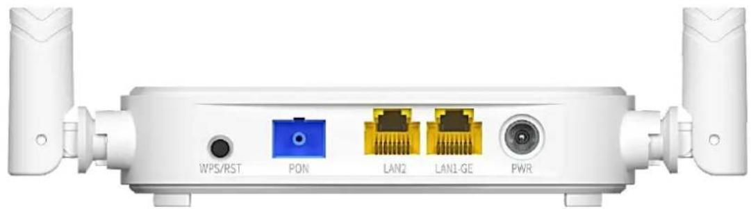
natural_image
Front view of a white wireless router with labeled ports (WPS/RST, PON, LAN2, LAN1-GE, PWR) and two antennas (no additional text or symbols visible)| Port/Button | Description |
| WPS/RST | WPS/Reset button.WPS:Wi-Fi-enabled devices can connect to the Wi-Fi networks of the ONT without entering the password through WPS negotiation.Press the button for 1 to 3 seconds to start the WPS negotiation process of the ONT. TheWLANLED indicator blink quickly. Within 2 minutes, enable the WPS function on a WPS-supported device to establish a WPS connection.Reset:Restore the ONT to the configurations preset by the ISP.After the ONT completes startup, press the button for more than 10 seconds and release it. All LED indicators will light off in a few seconds. When thePWRLED indicator lights solid on again, the ONT is restored to the configurations preset by the ISP. |
| PON | Optical fiber port.Used to connect to a fiber cord. |
| LAN1-GE/LAN2 | LAN1-GE: 1000 Mbps LAN portLAN2: 100 Mbps LAN portUsed to connect to a router, switch, computer or IPTV set-top box. |
| PWR | Power jack.Please use the included power adapter to connect the ONT to a power source. |
1.2.2 Label
The label is located on the bottom panel of the ONT. See the following figure for details.
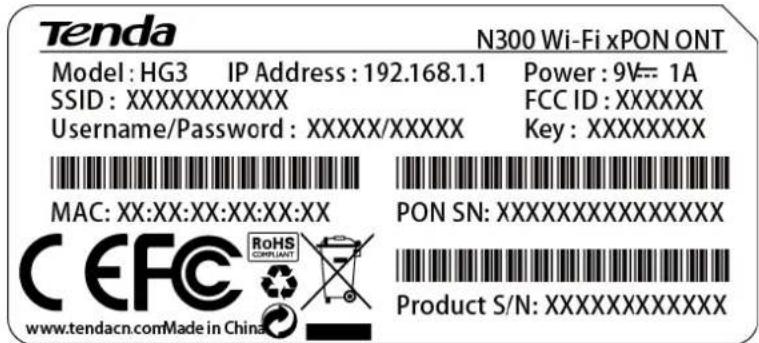
Model: Model of the ONT
IP Address: Default IP address used to log in to the web UI of the ONT
Power: Power supply for the ONT
SSID & Key: Default Wi-Fi name and password of the ONT
Username/Password: Default user name and password used to log in to the web UI of the ONT
MAC Address: MAC address of the ONT
PON SN: PON serial number of the ONT
Product S/N: Product serial number
2 Web UI
2.1 Login
Step 1 Connect the ONT to a power source using the provided power adapter.
Step 2 Connect a computer to a LAN port of the ONT using an Ethernet cable, or connect your smartphone to the Wi-Fi network of the ONT.
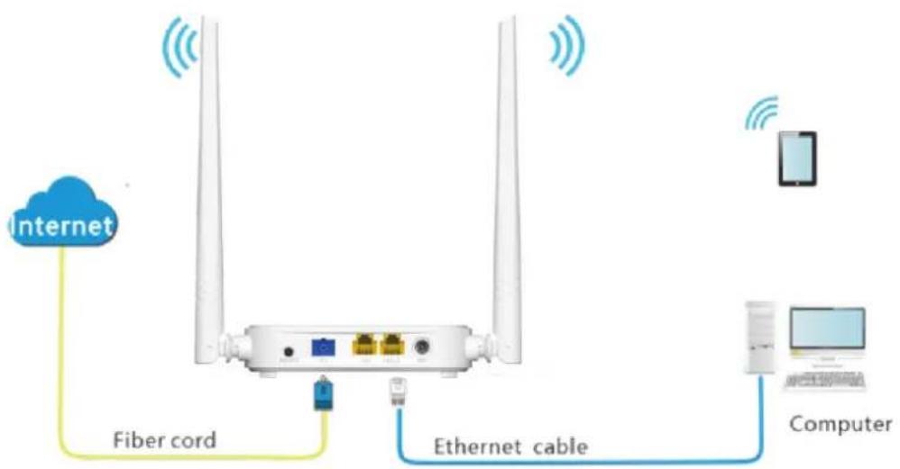
Step 3 Start a web browser on a connected device and visit the IP address of the ONT (192.168.1.1 by default). Enter your User Name and Password (both are admin by default), and click Login.
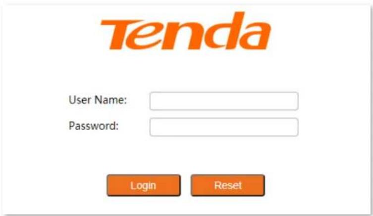
---End

If the above page does not appear, try the following solutions:
• Ensure that the ONT is powered on properly.
If a wired device, such as a computer, is used for configuration, ensure that the wired device is connected to a LAN port of the router properly, and is set to obtain an IP address automatically.
- If a wireless device, such as a smartphone, is used for configuration, ensure that the wireless device is connected to the Wi-Fi network of the ONT and the cellular network (mobile data) of the client is disabled.
- Restore the ONT to factory settings and try again.
The following page appears.
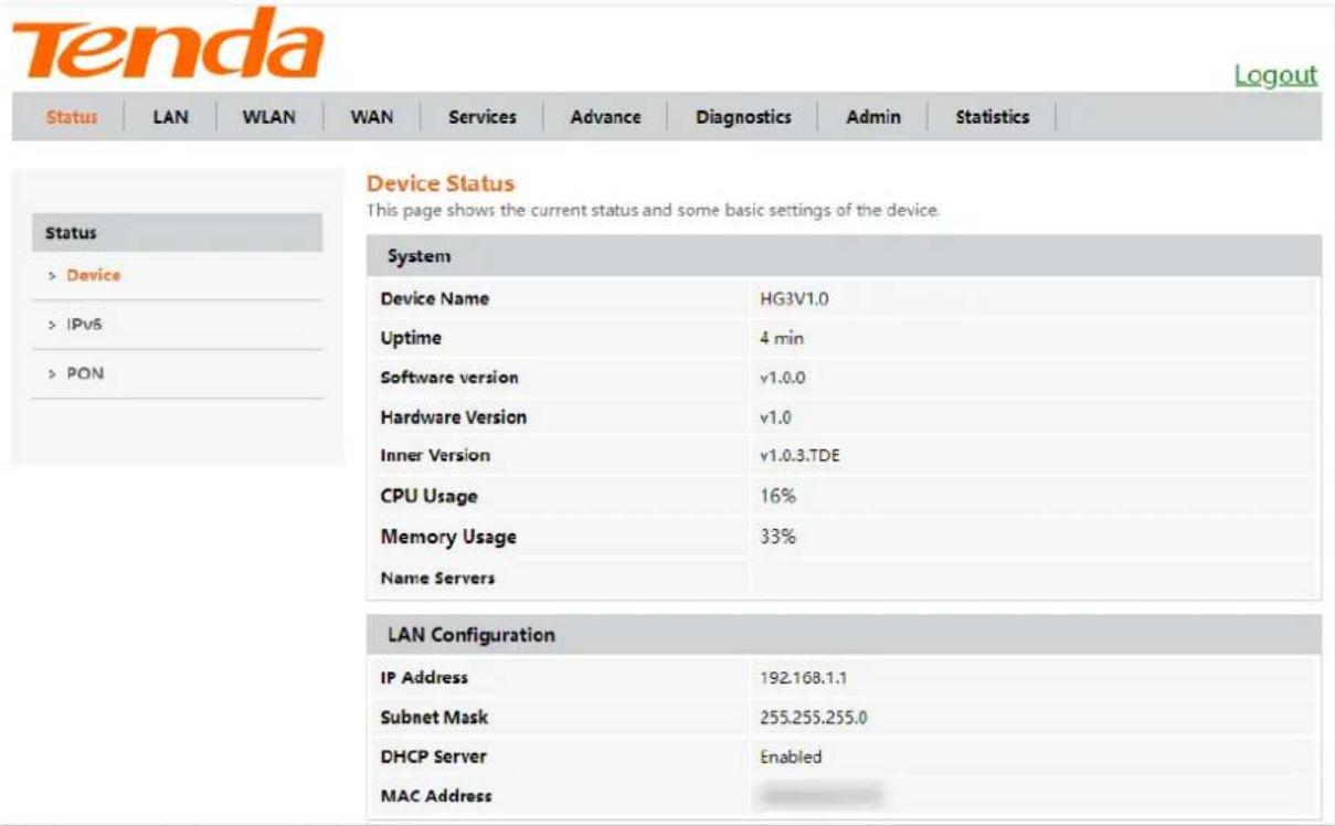
2.2 Logout
The ONT logs you out when you:
- Click the Logout button on the upper-right corner of the web UI, or click Logout in Admin > Logout.
- Perform no operation within 20 minutes.
2.3 Web UI layout
The web UI of the ONT is composed of 4 parts, including the level-1 navigation tree, level-2 navigation tree, tab page area, and configuration area. See the following figure.
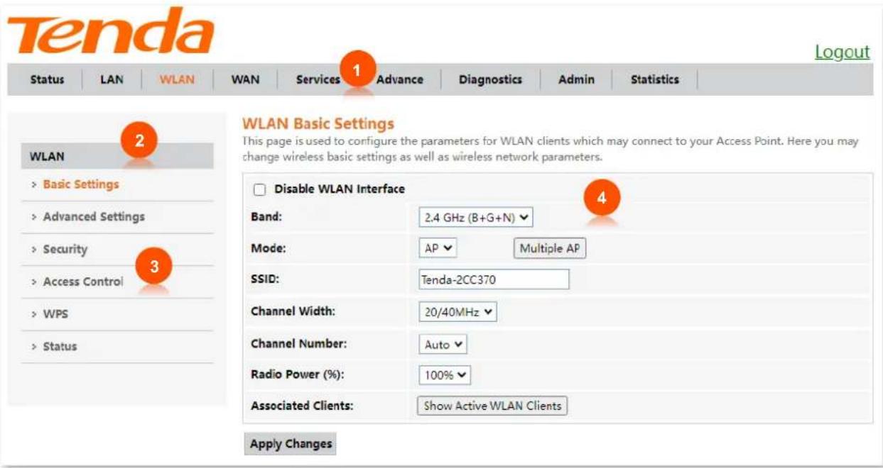
| No. | Name | Description |
| 1 | Level-1 navigation tree | The navigation bars and tab pages display the function menu of the ONT. When you select a function in the navigation bar, the configuration of the function appears in the configuration area. |
| 2 | Level-2 navigation tree | |
| 3 | Tab page area | |
| 4 | Configuration area | It enables you to view and modify the configuration. |
2.4 Common buttons
Some buttons are commonly used in the web UI of the ONT, and their functions are listed as follows.
| Button | Description |
| Refresh | It is used to refresh the statistics shown on the page. |
| Add | It is used to add the information that you entered. |
| Reset | It is used to restore the information that you entered on the page. |
| Delete | |
| Delete Selected | They are used to delete the information that you selected. |
| Delete All | |
| Modify | It is used to modify the information that you selected. |
| Remove | It is used to remove the information that you selected. |
| Apply | |
| Apply Changes | They are used to apply the settings configured on the page. |
3 Status
In this module, you can:
- View device status of the ONT.
- View IPv6 status of the ONT.
- View PON status of the ONT.
3.1 Device status
On this page, you can view the basic system information, LAN configuration and WAN configuration of the ONT.
To access the page, log in to the web UI of the ONT and choose Status > Device.
| System | |
| Device Name | HG3V1.0 |
| Uptime | 2 min |
| Software version | v1.0.0 |
| Hardware Version | v1.0 |
| Inner Version | v1.0.3.TDE |
| CPU Usage | 8% |
| Memory Usage | 33% |
| Name Servers | |
| LAN Configuration | |
| IP Address | 192.168.1.1 |
| Subnet Mask | 255.255.255.0 |
| DHCP Server | Enabled |
| MAC Address | C83A352CC370 |
| WAN Configuration | ||||||
| Interface | VLAN ID | Connection Type | Protocol | IP Address | Gateway | Status |
| nas0_0 | 20 | INTERNET | Bridged | down | ||
Parameter description
| Parameter | Description | |
| System | It displays the basic system information of the ONT, including the device name, uptime, software version, hardware version, CPU usage, memory usage and DNS address information. | |
| LAN Configuration | IP Address | It specifies the LAN IP address of the ONT, which is also the IP address used to log in to the web UI of the ONT. |
| Subnet Mask | It specifies the LAN subnet mask of the ONT. | |
| DHCP Server | It specifies whether the DHCP server of the ONT is enabled. | |
| MAC Address | It specifies the MAC address of the ONT's LAN port. | |
| WAN Configuration | Interface | It specifies the name of the interface/WAN connection when IPv4 is enabled. |
| VLAN ID | It specifies the VLAN ID of the WAN connection. | |
| Connection Type | It specifies the WAN connection type. | |
| Protocol | It specifies the channel mode used by the WAN port. | |
| IP Address | They specify the IP address and gateway address that the ONT obtains after you set up a WAN connection successfully. | |
| Gateway | ||
| Status | It specifies the connection status of the WAN connection.up: The WAN connection is successful and currently available.down: The WAN connection failed and is currently unavailable. | |
3.2 IPv6 status
On this page, you can view the IPv6 connection status of the ONT.
To access the page, log in to the web UI of the ONT and choose Status > IPv6.
| LAN Configuration | |||||
| IPv6 Address | 240e:fa:c662:ce3b:ca3a:35ff:fe80:3e68/64 | ||||
| IPv6 Link-Local Address | fe80::1/64 | ||||
| Prefix Delegation | |||||
| Prefix | 240e:fa:c662:ce3b::/64 | ||||
| WAN Configuration | |||||
| Interface | VLAN ID | Connection Type | Protocol | IP Address | Status |
| ppp0_nas0_0 | 47 | INTERNET | PPPoE | 240e:fa:c662:ce3a:ca3a:35ff:fe80:3e6f/64 | up |
Parameter description
| Parameter | Description | |
| LANConfiguration | IPv6 Address | It specifies the LAN IPv6 address of the ONT. |
| IPv6 Link-Local Address | It specifies the IPv6 link-local address of the ONT.A link-local address is an IPv6 unicast address that is automatically configured on any interface and is valid only for communications within the network segment. | |
| Prefix Delegation | Prefix | It specifies the IPv6 prefix of the LAN port of ONT. |
| WANConfiguration | Interface | It specifies the name of the interface/WAN when IPv6 is enabled. |
| VLAN ID | It specifies the VLAN ID of the WAN connection. | |
| Connection Type | It specifies the WAN connection type. | |
| Protocol | It specifies the channel mode used by the WAN port. | |
| IP Address | They specify the IP address and gateway address that the ONT obtains after you set up a WAN connection successfully. | |
| Gateway | ||
| Status | It specifies the connection status of the WAN connection.up: The WAN connection is successful and currently available.down: The WAN connection failed and is currently unavailable. | |
3.3 PON status
On this page, you can view the PON status and GPON/EPON connection status of the ONT.
To access the page, log in to the web UI of the ONT and choose Status > PON.
| PON Status | |
| Vendor Name | |
| Temperature | 43.105469 C |
| Voltage | 3.329700 V |
| Tx Power | -inf dBm |
| Rx Power | -inf dBm |
| Bias Current | 6,250000 mA |
| GPON Status | |
| ONU State | O1 |
Parameter description
| Parameter | Description | |
| PON Status | Vendor Name | It specifies the vendor name of the ONT. |
| Temperature | It specifies the current chip temperature of the ONT. | |
| Voltage | It specifies the current voltage of the optical module of the ONT. | |
| Tx Power | It specifies the transmitted and received optical power of the ONT over the PON port. | |
| Rx Power | ||
| Bias Current | It specifies the current bias current of the optical module of the ONT. | |
| GPON Status | ONU State | It specifies the state of the ONT, ranging from O1 to O7.•O1 to O4: The ONT is registering.•O5: The ONT registered successfully and is under normal operation.•O6/O7: The ONT is in abnormal state and stops transmitting signals. |
| EPON Status | Auth state | It specifies the state of the ONT. |
4 LAN
In this module, you can configure the LAN IPv4 and IGMP/MLD Snooping settings of the ONT.
To access the page, log in to the web UI and choose LAN.
| InterfaceName: | br0 |
| IP Address: | 192.168.1.1 |
| Subnet Mask: | 255.255.255.0 |
| IGMP/MLD Snooping: | ○ Disabled ○ Enabled |
Parameter description
| Parameter | Description |
| InterfaceName | It specifies the LAN interface name of the ONT. |
| IP Address | It specifies the IPv4 LAN address of the ONT, which is also the IPv4 address for logging in to the web UI of the ONT. |
| Subnet Mask | It specifies the IPv4 LAN subnet mask of the ONT. |
| IGMP/MLD Snooping | When Internet Group Management Protocol (IGMP) snooping is enabled, multicast data from known IPv4 multicast groups are multicast to the specified LAN ports only, instead of all LAN ports, thus saving link bandwidth.Standard mode: If no member joins a multicast group, the data of that multicast group is broadcast. If a member joins a multicast group, the data of that multicast group is only forwarded to the LAN port of the member.Blocking mode: If no member joins a multicast group, the data of that multicast group is discarded. If a member joins a multicast group, the data of that multicast group is only forwarded to the LAN port of the member.MLD is used by IPv6 routers for discovering multicast listeners on a directly attached link. If disabled on layer2 devices, IPv6 multicast data packets will be broadcast on the entire layer2; if enabled, these packets will be multicast to only specified recipient instead of being broadcast on the entire layer2. |
5 WLAN
In this module, you can customize your Wi-Fi network, including:
- Customize Wi-Fi name and other basic settings
– Hide Wi-Fi name and set other advanced functions - Customize Wi-Fi password
- Allow certain clients to access the Wi-Fi network
5.1 Basic settings
5.1.1 Overview
On this page, you can set basic parameters of the Wi-Fi network of the ONT, such as enabling/disabling the Wi-Fi network and setting band and SSID (Wi-Fi name).
To access the page, log in to the web UI of the ONT and choose WLAN > Basic Settings.
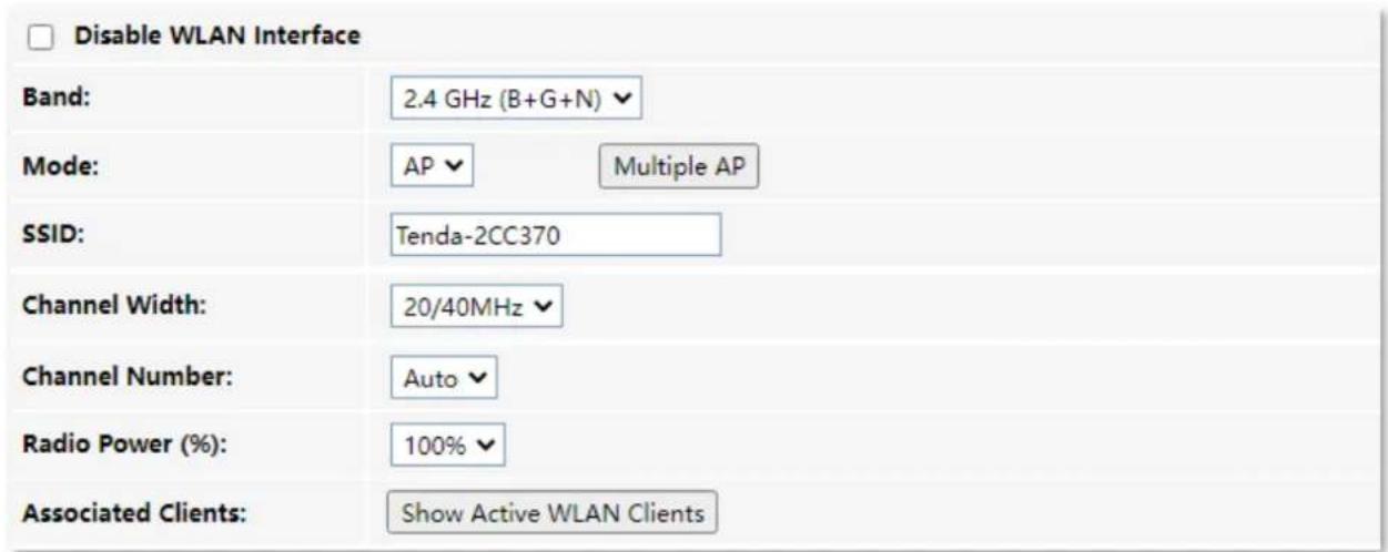
Parameter description
| Parameter | Description |
| Disable WLAN Interface | It specifies whether to enable the Wi-Fi network. |
| Band | It specifies the wireless band and protocol of the Wi-Fi network.2.4 GHz (B): In this mode, the 2.4 GHz wireless devices compliant with IEEE 802.11b protocol can connect to the 2.4 GHz wireless network of the ONT. The maximum wireless rate is 11 Mbps.2.4 GHz (G): In this mode, the 2.4 GHz wireless devices compliant with IEEE 802.11g protocol can connect to the 2.4 GHz wireless network of the ONT. The maximum wireless rate is 54 Mbps.2.4 GHz (B+G): In this mode, the 2.4 GHz wireless devices compliant with IEEE 802.11b or IEEE 802.11g protocol can connect to the 2.4 GHz wireless network of the ONT.2.4 GHz (N): In this mode, the 2.4 GHz wireless devices compliant with IEEE 802.11n protocol can connect to the 2.4 GHz wireless network of the ONT. The maximum wireless rate is 300 Mbps.2.4 GHz (G+N): In this mode, the 2.4 GHz wireless devices compliant with IEEE 802.11g or IEEE 802.11n protocol can connect to the 2.4 GHz wireless network of the ONT.2.4 GHz (B+G+N): In this mode, the 2.4 GHz wireless devices compliant with IEEE 802.11b, IEEE 802.11g or IEEE 802.11n protocol can connect to the 2.4 GHz wireless network of the ONT. |
| Mode | It specifies the wireless operation mode of the ONT.AP: The ONT serving as a wireless access point provides a wireless network for wireless clients. |
| Multiple AP | You can click Multiple AP to create more wireless networks of the same band.No.: It specifies the No. of the AP Wi-Fi network.Enable: It specifies whether to enable the AP Wi-Fi network.Band: It specifies the wireless band and protocol of the AP Wi-Fi network.SSID: It specifies the Wi-Fi name of the AP Wi-Fi network.Broadcast SSID: It specifies whether to hide the SSID of the AP Wi-Fi network. Enabled means that the SSID is displayed. Disabled means that the SSID is hidden, and you need to enter the SSID of the Wi-Fi network manually to connect to it.Active Client List: You can click it to view the information of clients connected to the Wi-Fi network.Reset: You can click it to discard the unsaved modifications on this page. |
| SSID | It specifies the Wi-Fi name of the main Wi-Fi network. |
| Channel Width | It specifies the bandwidth of the wireless channel of the Wi-Fi network.20MHz: It indicates that the channel bandwidth used by the ONT is 20 MHz.40MHz: It indicates that the channel bandwidth used by the ONT is 40 MHz.20/40MHz: It specifies that the ONT can switch its channel bandwidth between 20 MHz and 40 MHz based on the ambient environment. |
| Channel Number | It specifies the channel in which the Wi-Fi network works.You are recommended to choose a channel with less interference for better wireless transmission efficiency. You can use a third-party tool to scan the Wi-Fi signals nearby to understand the channel usage situations.Auto: It indicates that the ONT automatically adjusts its operating channel according to the ambient environment. |
| Radio Power (%) | You can set the intensity of the radio power of the ONT. A higher radio power brings a wider coverage of Wi-Fi coverage. |
| Associated Clients | You can view the clients that connect to the Wi-Fi network by clicking Show Active WLAN Clients.MAC Address: It specifies the MAC address of the client connected to the Wi-Fi network.Tx Packets: It specifies the number of transmitted packets of the client through the Wi-Fi network.Rx Packets: It specifies the number of received packets of the client through the Wi-Fi network.Tx Rate (Mbps): It specifies the transmitting rate of the Wi-Fi network.RSSI: It specifies the signal strength of the client received by the AP. |
5.1.2 Customize the main Wi-Fi name
Step 1 Choose WLAN > Basic Settings on the web UI.
Step 2 Set SSID.
Step 3 Click Apply Changes.
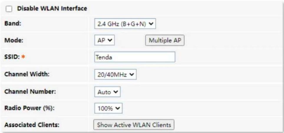
---End
After completing the configuration, you can search the SSID(s) on your Wi-Fi-enabled devices and connect to it to access the internet.
5.1.3 Enable multiple wireless networks
Step 1 Choose WLAN > Basic Settings on the web UI.
Step 2 Click Multiple AP. Select Enable to enable any Wi-Fi network as required, set SSID (Wi-Fi name), and click Apply Changes.
| No. | Enable | Band | SSID | Broadcast SSID | Active Client List |
| AP1 | 2.4 GHz (B+G+N) | AP-1 | Enabled | Show | |
| AP2 | 2.4 GHz (B+G+N) | AP-2 | Enabled | Show | |
| AP3 | 2.4 GHz (B+G+N) | AP-3 | Enabled | Show | |
| AP4 | 2.4 GHz (B+G+N) | AP-4 | Enabled | Show |
---End
After completing the configuration, you can search the SSID(s) on your Wi-Fi-enabled devices and connect to it to access the internet.
5.2 Advanced settings
5.2.1 Overview
On this page, you can configure more advanced settings of your Wi-Fi network.
To access the page, log in to the web UI of the ONT and choose WLAN > Advanced Settings.

You are recommended to retain the default settings if without professional guidance.
| RTS Threshold: | 2347 (0-2347) |
| Beacon Interval: | 100 (100-1024 ms) |
| DTIM Period: | 1 (1-255) |
| Broadcast SSID: | ● Enabled ○ Disabled |
Parameter description
| Parameter | Description |
| RTS Threshold | It specifies the frame length threshold for triggering the RTS/CTS mechanism in the unit of byte. If a frame exceeds this threshold, the RTS/CTS mechanism is triggered to reduce conflicts.Set the RTS threshold based on the actual situation. An excessively small value increases the RTS frame transmission frequency and bandwidth requirement. A higher RTS frame transmission frequency enables a wireless network to recover from conflicts quicker. For a wireless network with high user density, you can lower this threshold to reduce conflicts.The RTS mechanism requires some network bandwidth. Therefore, it is triggered only when frames exceed this threshold. |
| Beacon Interval | It specifies the interval at which this device sends Beacon frames.Beacon frames are sent at the interval to announce the existence of a wireless network. Generally, a smaller interval allows wireless clients to connect to this device sooner, while a larger interval allows the wireless network to transmit data quicker. |
| DTIM Period | It specifies the countdown before this device transmits broadcast and multicast frames in its cache. The unit is Beacon interval.For example, if DTIM Interval is set to 1, this device transmits all cached frames at one Beacon interval.It is used when the client is in power-saving mode, and the ONT informs the client about the presence of buffered multicast/broadcast data on the ONT at the specified interval. A proper value helps improve the power efficiency of clients. |
| Broadcast SSID | It specifies whether to broadcast or hide the SSID (Wi-Fi name) of the main Wi-Fi network.If the SSID is hidden, it cannot be found on clients and you need to enter the information of the Wi-Fi network on your clients manually to connect to it. |
5.2.2 Hide the main Wi-Fi name
Step 1 Choose WLAN > Advanced Settings on the web UI.
Step 2 Select Disabled for Broadcast SSID.
| RTS Threshold: | 2347 (0-2347) |
| Beacon Interval: | 100 (100-1024 ms) |
| DTIM Period: | 1 (1-255) |
| Broadcast SSID: | ○ Enabled ● Disabled |
Step 3 Click Apply Changes.
---End
After the configuration is completed, the SSID (Wi-Fi name) of the Wi-Fi network is hidden, but you can connect to the Wi-Fi network by entering its SSID and other required parameters.
5.3 Security
5.3.1 Overview
On this page, you can perform password settings to secure your Wi-Fi network.
To access the page, log in to the web UI of the ONT and choose WLAN > Security.
| SSID Type: | Root AP - Tenda-2CC370 |
| Encryption: | WPA2 Mixed |
| Pre-Shared Key: | ...... |
Parameter description
| Parameter | Description |
| SSID Type | It specifies the Wi-Fi network to be configured. |
| Encryption | It specifies the encryption mode of the Wi-Fi network.NONE: It indicates that the Wi-Fi network is not encrypted and clients can connect to it without password.WPA: It indicates that the Wi-Fi network is encrypted using WPA-PSK, which has better compatibility than WPA2-PSK.WPA2: It indicates that the Wi-Fi network is encrypted using WPA2-PSK, which has a higher security level than WPA-PSK.WPA2 Mixed: It indicates that the Wi-Fi network is encrypted using both WPA-PSK and WPA2-PSK, providing both security and compatibility. |
| Pre-Shared Key | It specifies the password for connecting to the Wi-Fi network. |
5.3.2 Customize the Wi-Fi password
Step 1 Choose WLAN > Security on the web UI.
Step 2 Select the SSID (Wi-Fi name) for which you want to customize the password in SSID Type.
Step 3 Set Encryption as required.
Step 4 Enter the Wi-Fi password in Pre-Shared Key.
| SSID Type: | Root AP - Tenda-2CC370 |
| Encryption: | WPA2 Mixed |
| Pre-Shared Key: | ...... |
Step 5 (Optional) Repeat Step 2 to Step 4 to set the Wi-Fi password for other SSIDs.
WLAN
Step 6 Click Apply Changes.
---End
After completing the configuration, you can connect the Wi-Fi networks using the Wi-Fi passwords you set.
5.4 Access control
5.4.1 Overview
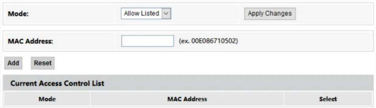
On this page, you can add and delete access control rules to decide which clients can or cannot connect to all the Wi-Fi networks in the frequency band.
To access the page, log in to the web UI of the ONT and choose WLAN > Access Control. Rules added are shown in Current Access Control List.
Parameter description
| Parameter | Description |
| Mode | It specifies the control mode.·Disabled: It indicates that the access control function is disabled.·Allow Listed: It indicates that only clients with the MAC addresses added to the list can connect to the Wi-Fi network.·Deny Listed: It indicates that clients with the MAC addresses added to the list cannot connect to the Wi-Fi network. |
| MAC Address | It specifies the MAC address of the client to be controlled. |
5.4.2 Allow certain clients to access the Wi-Fi network
Assume that you only want to enable a smartphone and a tablet to access your Wi-Fi network and prevent misuse of others. The MAC addresses of smartphone and tablet are:
- Smartphone: 8E:5B:54:F6:E1:00
- Tablet: 8C:EC:4B:B3:04:92
Configuring procedure:
Step 1 Choose WLAN > Access Control on the web UI.
Step 2 Select Allow Listed for Mode, and click Apply Changes.

Step 3 Enter 8E5B54F6E100 in MAC Address, and click Add.

Step 4 Enter 8CEC4BB30492 in MAC Address, and click Add.
---End
After the configuration is completed, the added devices are listed in Current Access Control List, and only the smartphone and tablet can connect to the Wi-Fi network.
| Current Access Control List | ||
| Mode | MAC Address | Select |
| Allow | 8e:5b:54:f6:e1:00 | |
| Allow | 8c:ec:4b:b3:04:92 | |

If the MAC address of a device is added in the Deny Listed mode, the device will fail to access the Wi-Fi network and a message indicating incorrect password will be displayed on the device.
5.5 WPS
5.5.1 Overview
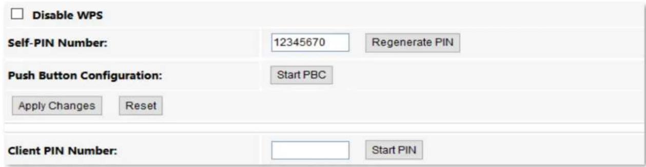
The Wi-Fi Protected Setup (WPS) function enables wireless clients that support WPS, such as smartphones, to connect to the Wi-Fi network of the ONT quickly and easily.
There are four methods to connect to the Wi-Fi network of the ONT through WPS.
- Connect to the Wi-Fi network using the WPS button
- Connect to the Wi-Fi network using PBC on the web UI
- Connect to the Wi-Fi network by entering PIN code of clients on the ONT
- Connect to the Wi-Fi network by entering PIN code of the ONT on clients
To access the page, log in to the web UI of the ONT and choose WLAN > WPS.
5.5.2 Connect to the Wi-Fi network using the WPS button
Step 1 Find the WPS/RST button on the ONT. Press it once and you can see the WLAN LED indicator blinks.
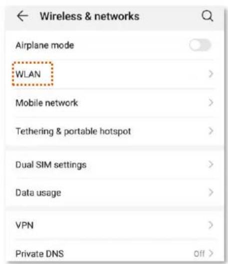
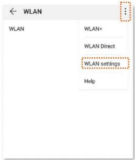
Step 2 Configure the WPS function on your wireless devices within 2 minutes. Configuration on various devices may differ (Example: HUAWEI P10 smartphone).
- Find Settings on the phone.
- Choose WLAN.
- Tap, and choose WLAN settings.
4. Choose WPS connection.
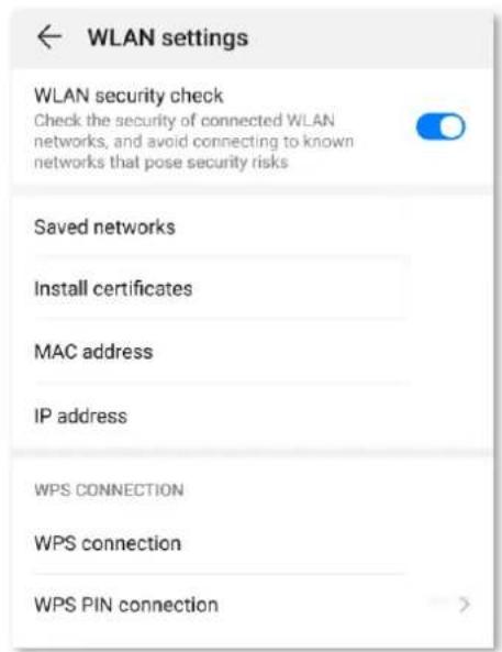
---End
Wait a moment until the WPS negotiation is completed, and the smartphone is connected to the Wi-Fi network.

- If multiple wireless networks are enabled in a frequency band, the main network is connected by default.
• To use the WPS function, the encryption mode of the wireless network must be WAP2 or not encrypted.
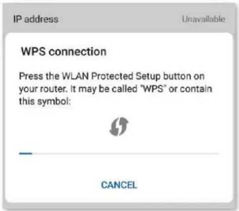
5.5.3 Connect to the Wi-Fi network using PBC on the web UI
Step 1 Get the ONT ready for WPS negotiation.
- Log in to the web UI of the ONT.
- Choose WLAN > WPS.
- Click Start PBC.
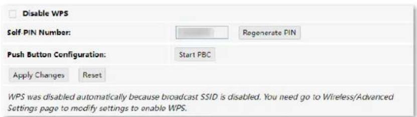
If the following message is displayed, the PBC is started successfully.
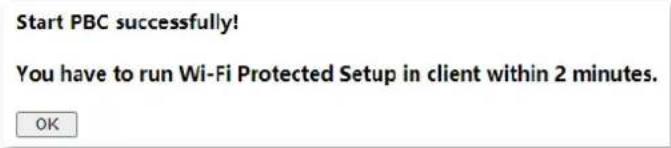
Step 2 Configure the WPS function on your wireless devices within 2 minutes. Configuration on various devices may differ (Example: HUAWEI P10 smartphone).
- Find Settings on the phone.
- Choose WLAN.
- Tap, and choose WLAN settings.
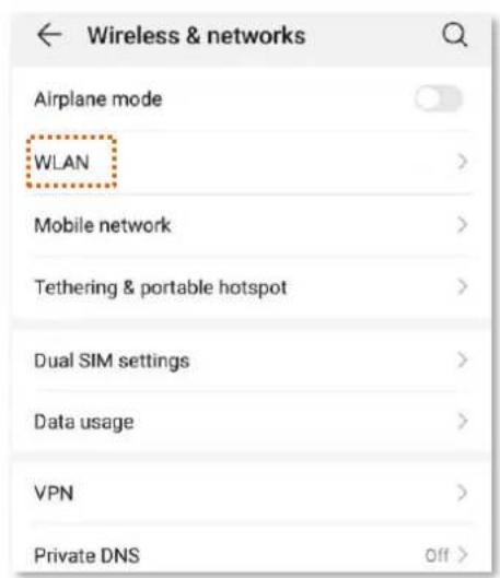
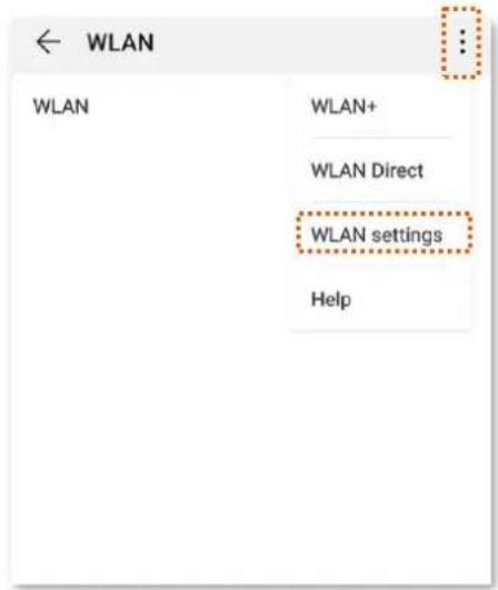
4. Choose WPS connection.
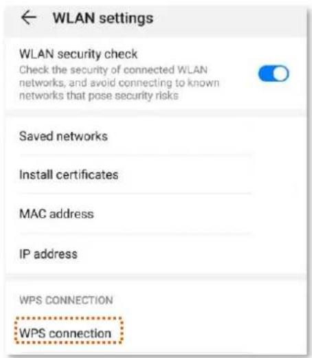
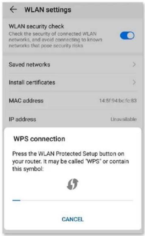
---End
Wait a moment until the WPS negotiation is completed, and the phone is connected to the Wi-Fi network.
TIP
• If multiple wireless networks are enabled in a frequency band, the main network is connected by default.
• To use the WPS function, the encryption mode of the wireless network must be WAP2 or not encrypted.
5.5.4 Connect to the Wi-Fi network by entering PIN code of clients on the ONT
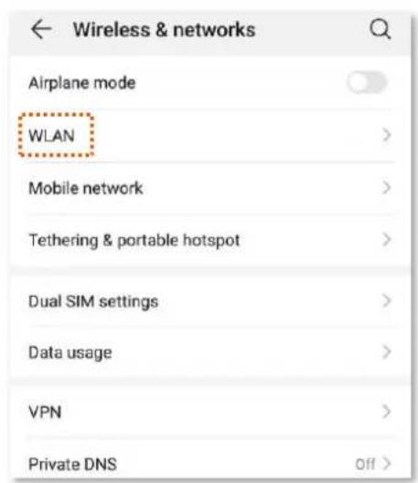
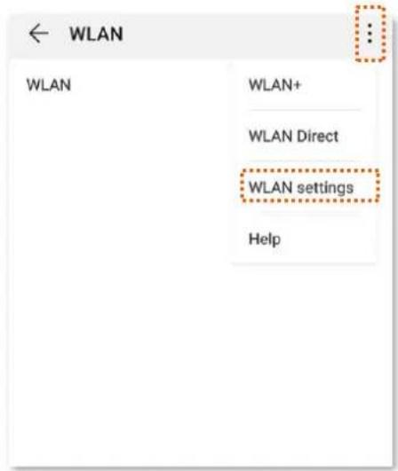
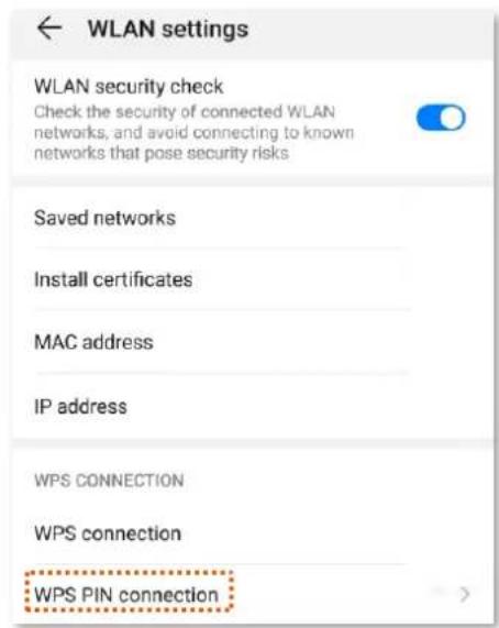
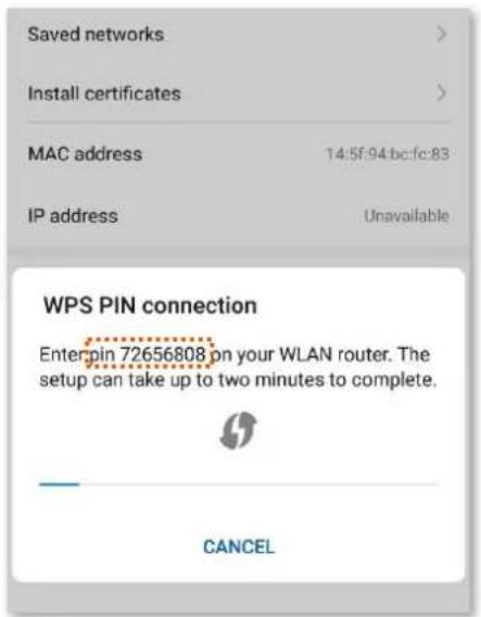
Step 1 Find the PIN code of the client. (The method differs with devices. HUAWEI P10 smartphone is used for illustration here.)
- Find Settings on the phone.
- Choose WLAN.
- Tap, and choose WLAN settings.
- Choose WPS PIN connection, and record the PIN code of the client.
Step 2 Start WPS connection on the ONT.
- Log in to the web UI of the ONT.
- Choose WLAN > WPS.
- Enter the PIN code in Client PIN Number and click Start PIN.
---End
After the ONT and the client finish WPS negotiation, the client connects to the Wi-Fi network of the ONT successfully.
TIP
• If multiple wireless networks are enabled in a frequency band, the main network is connected by default.
• To use the WPS function, the encryption mode of the wireless network must be WAP2 or not encrypted.
5.5.5 Connect to the Wi-Fi network by entering PIN code of the ONT on clients
TIP
This method is usually used on Wi-Fi network adapters. Please refer to the user guide of the Wi-Fi network adapter for configuration details.
Configuring procedure:
Step 1 Choose WLAN > WPS on the web UI. Find and record the Self-PIN Number of the ONT.

Step 2 Enter the PIN code on the wireless device that supports WPS connection using PIN code.
---End
Wait a moment until the WPS negotiation is completed, and the wireless device is connected to the WiFi network.
TIP
- If multiple wireless networks are enabled in a frequency band, the main network is connected by default.
• To use the WPS function, the encryption mode of the wireless network must be WAP2 or not encrypted.
5.6 Status
On this page, you can check the information and status of the Wi-Fi network you set up.
To access the page, log in to the web UI of the ONT and choose WLAN > Status.
| WLAN Configuration | |
| Mode | AP |
| Band | 2.4 GHz (B+G+N) |
| SSID | Tenda- |
| Channel Number | 3 |
| Encryption | WPA2 Mixed |
| BSSID | |
| Associated Clients | 0 |
Parameter description
| Parameter | Description |
| Mode | It specifies the mode of the Wi-Fi network. |
| Band | It specifies the wireless band and protocol of the Wi-Fi network. |
| SSID | It specifies the Wi-Fi name of the Wi-Fi network. |
| Channel Number | It specifies the channel in which the Wi-Fi network works. |
| Encryption | It specifies the encryption mode of the Wi-Fi network. |
| BSSID | Basic Service Set Identifier (BSSID) is used to describe sections of a wireless local area network. This service set is the MAC address of the AP's radio for clients to identify and connect to. |
| Associated Clients | It specifies the number of connected clients. |
6 WAN
6.1 Overview
After you have registered the ONT successfully, you can set up the WAN connection.

You can set up WAN connections to access different types of services or a combination of them, including internet, TR069, and others. Internet is used for illustration in this chapter unless specified.
The ONT can work under the following two modes:
- Bridge mode: The channel mode is set to Bridged. To access the internet, you can set up an internet connection (PPPoE, DHCP, or static IP) on a computer or router connected to the ONT.
- Router mode: The channel mode is set to IPoE, PPPoE or 6rd. To access the internet, you can set up WAN connections on the ONT.

Under the bridge mode, you can only access the internet through the LAN ports of the ONT. Under the router mode, you can access the internet through both the LAN ports and Wi-Fi networks of the ONT.
To access the configuration page, log in to the web UI of the ONT and choose WAN > PON WAN. Required settings for WAN connections differ with the channel modes, connection types and IP protocols that you choose.
Common WAN settings
This part shows the common settings in all types of WAN connections.
![nas0_0 Enable VLAN: VLAN ID: 20 802.1p_Mark 0 Multicast Vlan ID: [1-4094] Channel Mode: Bridged Admin Status: Enable Disable Connection Type: INTERNET Enable IGMP-Proxy: Enable MLD-Proxy:](/content/2026/05/828621/images/9a56d0a4da2a24a906db74d2daa06cfde65efcfba16e97944879a4b01aff720b.jpg)
Parameter description
| Parameter | Description |
| nas0_0 | It specifies the WAN connection name which you set up.You can add multiple WAN connections by clicking the drop-down list and choose new link. After configuring required parameters, you can clickApply Changeto save the connections.This parameter is generated automatically after you create a new link and cannot be customized. A maximum of eight links can be created here. |
| Enable VLAN | If the WAN connection you want to set up includes VLAN information, you can select |
| VLAN ID | Enable VLANand set the VLAN IDas required. |
| 802.1p_Mark | This parameter is available only when theEnable VLANfunction is enabled. It specifies the 802.1P priority. Data with a larger priority value takes a higher priority to be processed. |
| Multicast Vlan ID: [1-4094] | This VLAN ID must already exist in 802.1Q VLAN and only ports in this VLAN can forward multicast packets. |
| Channel Mode | It specifies the mode that you used to set up the WAN connection, includingBridged, IPoE, PPPoE and6rd.Bridged: Select this type when this device only serves as a modem, and you want to set up a dial-up connection or enter other internet parameters directly on your computer for internet access.IPoE: Select DHCP if your ISP does not provide any parameters to you for internet access, and selectFixed IP if your ISP provides a static IP address and other related information to you for internet access.PPPoE: Select this type if your ISP provides a user name and password to you for internet access.6rd: Select this type when you want to deploy the IPv6 network rapidly based on IPv4 infrastructures. |
| Enable Bridge | It specifies whether to enable the bridge function. |
| Admin Status | It specifies whether to enable this WAN connection. |
| Connection Type | It specifies the WAN connection type. Choose the proper connection type as required by your ISP.OtherTR069INTERNETINTERNET_TR069 |
| MTU | Maximum Transmission Unit (MTU) is the largest data packet transmitted by a network device. When the channel mode is PPPoE, the default MTU value is 1492. When the channel mode is IPoE, the default MTU value is 1500. Do not change the value unless necessary. |
| Enable IGMP-Proxy | It specifies whether to enable the Internet Group Management Protocol (IGMP) Proxy. If you are not sure, keep the default setting or consult your ISP.IGMP Proxy is used to manage multicast data and reduce traffic replication. IGMP proxy enables a device to issue IGMP host messages on behalf of its users, reducing IGMP messages and the load for the uplink device. |
| Enable MLD-Proxy | It specifies whether to enable the Multicast Listener Discovery (MLD) Proxy. If you are not sure, keep the default setting or consult your ISP.MLD is the IPv6 equivalent of IGMP. |
| IP Protocol | It specifies the adopted IP protocol version.IPv4: Select this option if IPv4 is used for communication.IPv6: Select this option if IPv6 is used for communication.IPv4/IPv6: Select this option if both IPv4 and IPv6 are used for communication. |
WAN IP settings
You can configure the WAN IPv4 address information in this part.
This part needs to be configured only when Channel Mode is set to IPoE and IP Protocol is set to IPv4 or IPv4/IPv6 or when Channel Mode is set to 6rd.
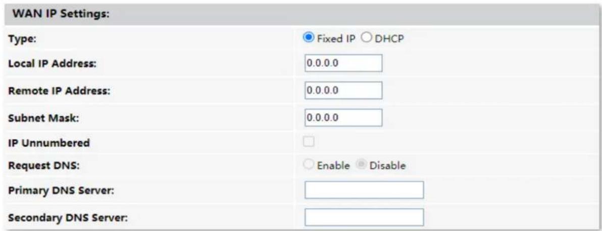
Parameter description
| Parameter | Description |
| Type | It specifies the method used by the ONT to obtain WAN IP address information.Fixed IP: You need to configure the local IP address, remote IP address (gateway address) and other related information manually.DHCP: The ONT obtains WAN IP address information automatically. Choose this type if your ISP does not provide related parameters. |
| Local IP Address | |
| Remote IP Address | If you select Fixed IP for Type, you should manually enter the IP address and related information provided by your ISP. |
| Subnet mask | |
| IP Unnumbered | It specifies whether to enable the IP unnumbered function.With it enabled, you can enable IP processing on a serial interface without assigning it a unique IP address. The IP unnumbered interface can "borrow" the IP address of another interface already configured on the router, which conserves network and address space.If it cannot be enabled on the web UI, this function is not supported. |
| Request DNS | If the IP address is obtained through DHCP, you can select Request DNS to obtain the DNS server address automatically. |
| Primary DNS Server | If the IP address obtaining type is Fixed IP or Request DNS function is disabled when the IP address obtaining type is DHCP, you should enter the DNS server address provided by your ISP. |
| Secondary DNS Server | If the ISP only provides one DNS server address, you can leave the secondary DNS blank. |
IPv6 WAN settings
You can configure the WAN IPv6 address information in this part.
When IP Protocol is set to IPv6 or IPv4/IPv6, and Channel Mode is set to IPoE or PPPoE, these parameters are required.
| IPv6 WAN Setting: | |
| Address Mode: | Stateless DHCPv6(SLAAC) |
| Request Options: | Request Prefix |
| Request DNS : | Enable Disable |
| Primary IPv6 DNS: | |
| Secondary IPv6 DNS: | |
Parameter description
| Parameter | Description |
| Address Mode | It specifies how the WAN IPv6 address of the ONT is obtained, including:Stateless DHCPv6 (SLAAC): Stateless Address Autoconfiguration (SLAAC) is a dynamic allocation method of IPv6 address, which enables the ONT to auto-generate IPv6 addresses with local information and those from the router advertisement.Static: You need to enter parameters related to IPv6 address manually.Stateful DHCPv6: DHCPv6 status settings are provided. The client obtains complete IPv6 address information (including DNS server address) from the DHCPv6 server. The gateway address is obtained through route advertisement (RA).Auto Detect Mode: The ONT automatically generates the IPv6 addresses based on the mode detected. |
| Request Options | You can enable the ONT to obtain the IPv6 address and prefix as a DHCPv6 client. |
| IPv6 Address | It specifies the IPv6 address and prefix length provided by your ISP when you select Static for Address Mode. |
| IPv6 Gateway | It specifies the IPv6 gateway address of the ONT when you select Static for Address Mode. |
| Request DNS | When Request DNS is set to Enable, the ONT obtains the IPv6 DNS server address from the DHCPv6 server. |
| Primary IPv6 DNS | When Request DNS is set to Disable, you need to set the primary and secondary DNS server addresses manually. |
PPP settings
You can configure the PPPoE parameters to access the internet in this part.
When Channel Mode is set to PPPoE, these parameters are required.
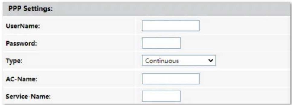
Parameter description
| Parameter | Description |
| UserName | They specify the PPPoE user name and password for settings up the WAN connection. |
| Password | |
| Type | It specifies the PPPoE connection type.Continuous: The ONT keeps connected to the internet.Connect on Demand: The ONT disconnects from the internet after a certain period and establishes the connection as soon as you attempt to access the internet.Manual: Users should manually connect and disconnect the network connection. |
| AC-Name | It specifies the PPPoE server name, for the ONT to verify the legitimacy of the PPPoE server.TIPIf your ISP did not provide a service name, leave this field blank. Otherwise, a dial failure may occur. |
| Service-Name | It specifies the PPPoE service name used by the PPPoE server to verify the legitimacy of the ONT.TIPIf your ISP did not provide a service name, leave this field blank. Otherwise, a dial failure may occur. |
6rd configuration
When you want to access a certain IPv6 network or service of your service provider through an IPv4 network and you are provided with related parameters, you can set up a 6rd connection.
When Channel Mode is set to 6rd, these parameters are required.
| 6rd Config: | |
| Board Router v4 Address: | |
| 6rd IPv4 Mask Len: | |
| 6rd Prefix (EX:"2001:db8::"): | |
| 6rd Prefix length: | |
Parameter description
| Parameter | Description |
| Board Router v4 Address | It specifies the IPv4 address of the remote border relay router. |
| 6rd IPv4 Mask Len | It specifies the length of the IPv4 subnet mask used for 6rd connection. The WAN IPv4 addresses of both ends must be in the same segment. |
| 6rd Prefix (EX:"2001:db8::") | It specifies the IPv6 prefix of the current network.If the 6rd channel is used for communication between IPv6 islands, you can customize the IPv6 prefix here.If the 6rd channel is used for accessing the ISP's IPv6 network, the IPv6 prefix must be provided by the ISP. |
| 6rd Prefix length | It specifies the 6rd prefix length. |
Port mapping
You can configure the port mapping options in this part. When certain interfaces are selected for the WAN connection, devices connected to these interfaces use the WAN connection to access the internet preferentially.
| Port Mapping: | |
| □ LAN_1 | □ LAN_2 |
| □ WLAN0 | |
| □ WLAN0-AP1 | □ WLAN0-AP2 |
| □ WLAN0-AP3 | □ WLAN0-AP4 |
6.2 Bridge mode
If you have a router and want to set up internet access on it, or you only want to access the internet on a certain computer, you can use the ONT under bridge mode.

When the ONT is under bridge mode, you can only access the internet through the downstream device used for setting up internet access.
Under bridge mode, the ONT acts as a bridging device between your LAN and your ISP. The ONT works under bridge mode by default.
The network topology of the scenario is shown as follows.
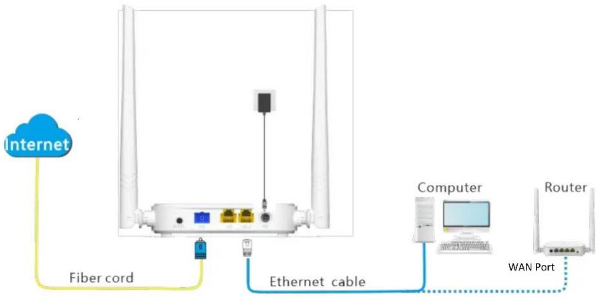
flowchart
graph TD
    A["Internet"] -->|Fiber cord| B["Fiber"]
    B --> C["Ethernet cable"]
    C --> D["Computer"]
    D --> E["WAN Port"]
    E --> F["Router"]
6.2.1 Configure internet access on a computer

Configure your computer to access the internet according to the parameters provided by your ISP. PPPoE is used for illustration here.
Configuring procedure:
Step 1 Connect your computer to a LAN port of the ONT.
Step 2 Right-click 📋 on the desktop and choose Network Connections.
Step 3 Choose Dial-up and click Set up a new connection.
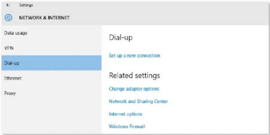
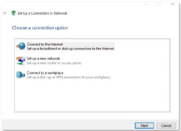
Step 4 Click Connect to the Internet and click Next.
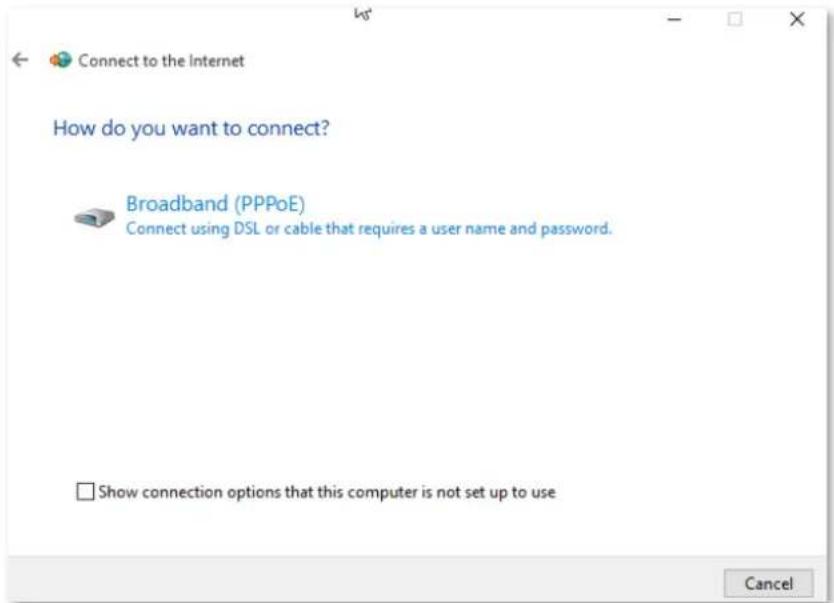
Step 5 Click Broadband (PPPoE).
Step 6 Enter the PPPoE User name and Password provided by your ISP and click Connect.
![Connect to the Internet Type the information from your Internet service provider (ISP) User name: [Name your ISP gave you] Password: [Password your ISP gave you] Show characters Remember this password Connection name: Broadband Connection Allow other people to use this connection This option allows anyone with access to this computer to use this connection. I don't have an ISP Connect Cancel](/content/2026/05/828621/images/8cb1ca134660ea230dc255e83dabcab592991d7534e59d9c15d255b04ea5b4de.jpg)
---End
After the configuration, you can access the internet on the computer.
6.2.2 Configure internet access on a router
Assume that your ISP provides you with the PPPoE user name and password.
Configuring procedure:
Step 1 Connect the WAN port of router to a LAN port of the ONT using an Ethernet cable.
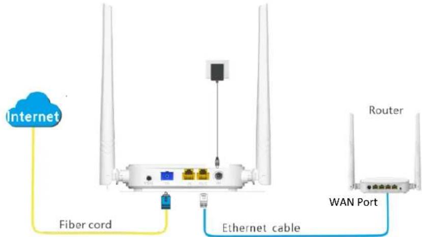
Step 2 Refer to the quick installation guide or user guide of your router to configure the internet access.
---End
After the configuration, you can access the internet through the router.
6.3 Router mode
If you want to set up WAN connections for one or multiple services on the ONT, and access the WAN connection through both the Wi-Fi networks of the ONT and LAN ports, you can set the ONT to router mode. Based on the information provided by your ISP, you need to complete different configurations on the web UI.
6.3.1 Set up a fixed IP connection
When your ISP provides fixed IP address (IPv4 or IPv6, or both) information, which may include the IP address, subnet mask and DNS server, you can set up a fixed IP connection.
Configuring procedure:
Step 1 Log in to the web UI of the ONT.
Step 2 Choose WAN > PON WAN.
Step 3 Set Channel Mode to IPoE.
Step 4 Set other common WAN parameters as required by your ISP.
![nas0_0 Enable VLAN: VLAN ID: 20 802.1p_Mark 0 Multicast Vlan ID: [1-4094] Channel Mode: IPoE Enable Bridge: Bridge Mode: Bridged Ethernet (Transparent Bridging) Admin Status: Enable Disable Connection Type: INTERNET MTU: 1500 Enable IGMP-Proxy: Enable MLD-Proxy: IP Protocol: IPv4/IPv6](/content/2026/05/828621/images/a705753dc42d5adc2f510aff875f9543b91b539a157d710f9a5ca93c18e537d0.jpg)
Step 5 Configure WAN IP Settings or/and IPv6 WAN Setting based on the IP protocol you choose.
- In the WAN IP Settings part, set Type to Fixed IP and configure other parameters as required.
In the IPv6 WAN Setting part, set Address Mode to Static and configure other parameters as required.
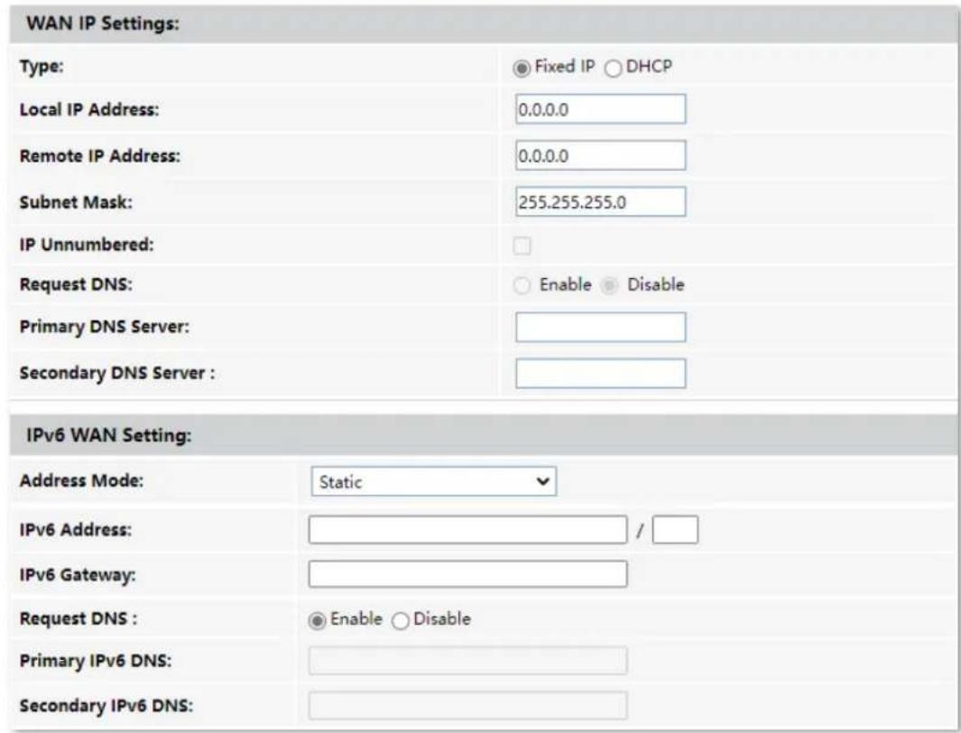
Step 6 (Optional) Configure Port Mapping as required.
| Port Mapping: | |
| □ LAN_1 | □ LAN_2 |
| □ WLAN0 | |
| □ WLAN0-AP1 | □ WLAN0-AP2 |
| □ WLAN0-AP3 | □ WLAN0-AP4 |
Step 7 Click Apply Changes.
---End
After the configuration, you can access the internet through the LAN ports or Wi-Fi networks of the ONT, or by connecting a router (connection type: DHCP/dynamic IP) to a LAN port of the ONT.
6.3.2 Set up a dynamic IP connection
If your ISP does not provide any parameters, you can try to set up a DHCP connection.
Configuring procedure:
Step 1 Log in to the web UI of the ONT.
Step 2 Choose WAN > PON WAN.
Step 3 Set Channel Mode to IPoE.
Step 4 Set other common WAN parameters as required by your ISP.
![nas0_0 Enable VLAN: VLAN ID: 20 802.1p_Mark 0 Multicast Vlan ID: [1-4094] Channel Mode: IPoE Enable Bridge: Bridge Mode: Bridged Ethernet (Transparent Bridging) Admin Status: Enable Disable Connection Type: INTERNET MTU: 1500 Enable IGMP-Proxy: Enable MLD-Proxy: IP Protocol: IPv4/IPv6](/content/2026/05/828621/images/9e2e3d5d540bc0c6a1c5aaf3ea6f0d41eb672e523b82c87c9a7df8931b60ff84.jpg)
Step 5 Configure WAN IP Settings or/and IPv6 WAN Setting based on the IP protocol you choose.
- In the WAN IP Settings part, set Type to DHCP and configure other parameters as required.
- In the IPv6 WAN Setting part, set Address Mode to Stateless DHCPv6(SLAAC) and configure other parameters as required.
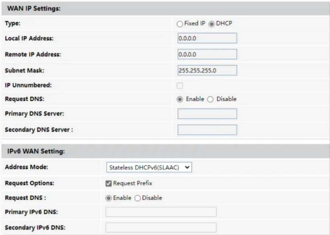
Step 6 (Optional) Configure Port Mapping as needed.
| Port Mapping: | |
| □ LAN_1 | □ LAN_2 |
| □ WLAN0 | |
| □ WLAN0-AP1 | □ WLAN0-AP2 |
| □ WLAN0-AP3 | □ WLAN0-AP4 |
Step 7 Click Apply Changes.
---End
After the configuration, you can access the internet through the LAN ports or Wi-Fi networks of the ONT, or by connecting a router (connection type: DHCP/dynamic IP) to a LAN port of the ONT.
6.3.3 Set up a PPPoE connection
If your ISP provides the PPPoE user name, password, and other related parameters (if any), you can set up a PPPoE connection.
Configuring procedure:
Step 1 Log in to the web UI of the ONT.
Step 2 Choose WAN > PON WAN.
Step 3 Set Channel Mode to PPPoE.
Step 4 Choose an IP Protocol in the drop-down list.
Step 5 Set other common WAN parameters as required by your ISP.
![nas0_0 Enable VLAN: VLAN ID: 20 802.1p_Mark 0 Multicast Vlan ID: [1-4094] Channel Mode: PPPoE Enable Bridge: Bridge Mode: Bridged Ethernet (Transparent Bridging) Admin Status: Enable Disable Connection Type: INTERNET MTU: 1492 Enable IGMP-Proxy: Enable MLD-Proxy: IP Protocol: IPv4/IPv6](/content/2026/05/828621/images/7c6deca353f95c73008a076f2bef57e4e990e63f7fdfa1bff08005f93c5f40ae.jpg)
Step 6 Enter the PPPoE UserName and Password provided by your ISP in PPP Settings.
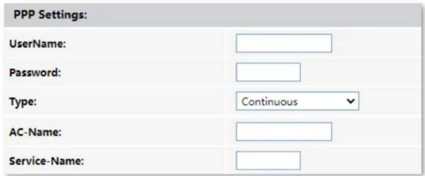
Step 7 (Optional) If you set IP Protocol to IPv6 or IPv4/IPv6, enter required parameters in IPv6 WAN Setting.
Step 8 (Optional) Configure Port Mapping as needed.
| Port Mapping: | |
| □ LAN_1 | □ LAN_2 |
| □ WLAN0 | |
| □ WLAN0-AP1 | □ WLAN0-AP2 |
| □ WLAN0-AP3 | □ WLAN0-AP4 |
Step 9 Click Apply Changes.
---End
After the configuration, you can access the internet through the LAN ports or Wi-Fi networks of the ONT, or by connecting a router (connection type: DHCP/dynamic IP) to a LAN port of the ONT.
6.3.4 Set up a 6rd connection
When you want to access a certain IPv6 network or service of your service provider through an IPv4 network and you are provided with related parameters, you can set up a 6rd connection.
Configuring procedure:
Step 1 Log in to the web UI of the ONT.
Step 2 Choose WAN > PON WAN.
Step 3 Set Channel Mode to 6rd.
Step 4 Set other common WAN parameters as required by your ISP.
![nas0_0 Enable VLAN: VLAN ID: 20 802.1p_Mark 0 Multicast Vlan ID: [1-4094] Channel Mode: 6rd Enable Bridge: Bridge Mode: Bridged Ethernet (Transparent Bridging) Admin Status: Enable Disable Connection Type: INTERNET MTU: 1500 Enable IGMP-Proxy: Enable MLD-Proxy:](/content/2026/05/828621/images/e80646845e08318fcd43e4f2c64f4fd9291e9c45cc99b8f0606b0eccd360b7b3.jpg)
Step 5 Set parameters in the WAN IP Settings part using the parameters provided by your ISP.
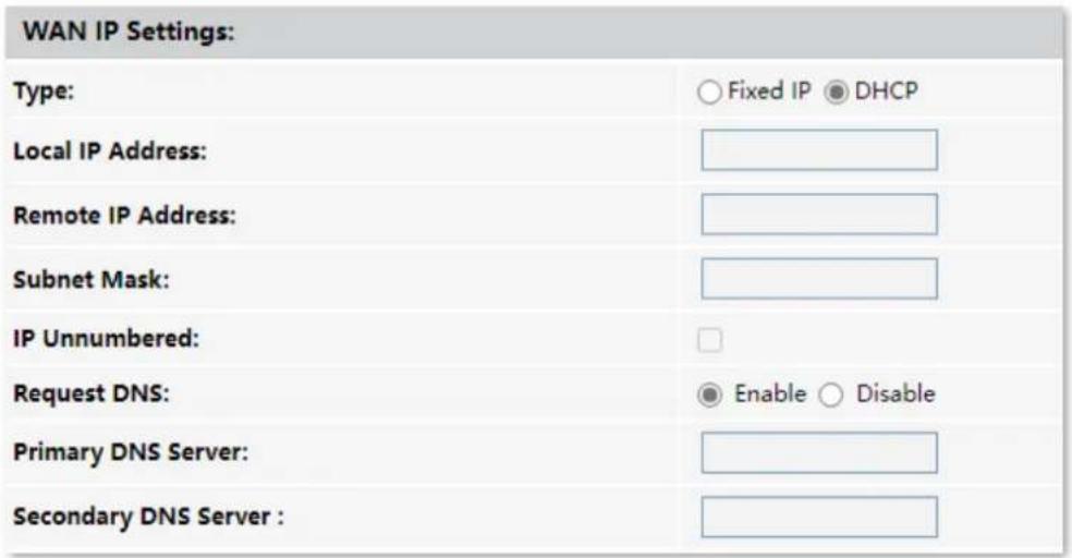
Step 6 Set parameters in the 6rd Config part using the parameters provided by your ISP.
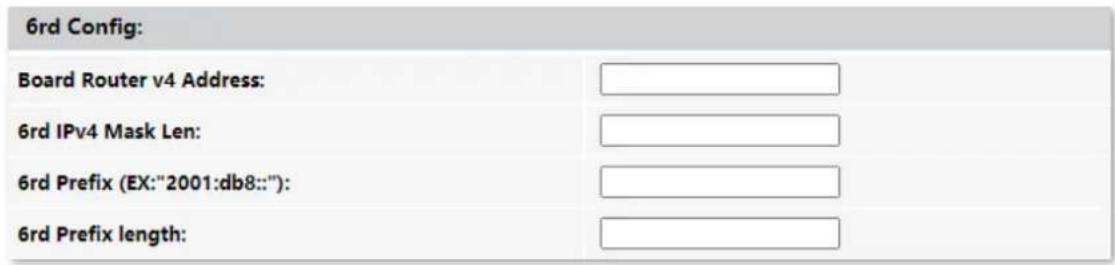
Step 7 (Optional) Configure Port Mapping as required.
| Port Mapping: | |
| □ LAN_1 | □ LAN_2 |
| □ WLAN0 | |
| □ WLAN0-AP1 | □ WLAN0-AP2 |
| □ WLAN0-AP3 | □ WLAN0-AP4 |
Step 8 Click Apply Changes.
---End
After the configuration, you can access the internet through the LAN ports or Wi-Fi networks of the ONT, or by connecting a router (connection type: DHCP/ dynamic IP) to a LAN port of the ONT.
7 Services
7.1 Service
7.1.1 DHCP
Overview
The DHCP server can automatically assign IP addresses, subnet masks, gateway addresses and DNS to LAN clients. When it is disabled, you need to manually configure the IP address information on the LAN device to access the internet. Disable it only when necessary.
To access the configuration page, log in to the web UI of the ONT and choose Services > Service > DHCP.
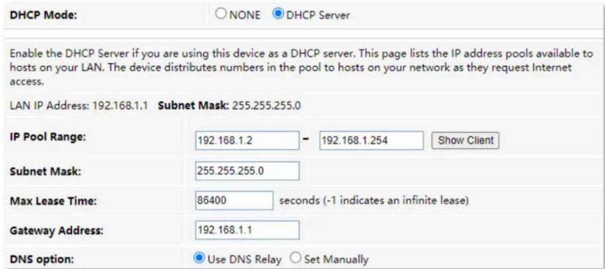
Parameter description
| Parameter | Description |
| DHCP Mode | It specifies the status of the DHCP server.NONE: The DHCP server is disabled.DHCP Server: The DHCP server is enabled. |
| LAN IP address | It specifies the current LAN IP address of the ONT, which is also the IP address used to log in to the web UI of the ONT. |
| Subnet Mask | It specifies the current subnet mask of the LAN. |
| IP Pool Range | It specifies the range of IP addresses that a DHCP server can assign to LAN clients. |
| Show Client | It shows information of the active DHCP clients, including:IP Address: It specifies the IP address assigned to the DHCP leased client.MAC Address: It specifies the MAC address of the DHCP leased client.Expired Time (sec): It specifies the time expired for the DHCP leased client. |
| Subnet Mask | It specifies the subnet mask of the DHCP clients. |
| Max Lease Time | It specifies the valid time of the IP addresses assigned by the DHCP server of the ONT to the DHCP clients. |
| Gateway Address | It specifies the gateway IP address of DHCP clients. |
| DNS option | It specifies how the ONT assigns DNS server addresses to LAN clients.Use DNS Relay: The ONT forwards the DNS query packets from LAN clients to an external DNS server.Set Manually: You need to set the DNS server address manually. You can set three DNS servers at most, and at least one is required. |
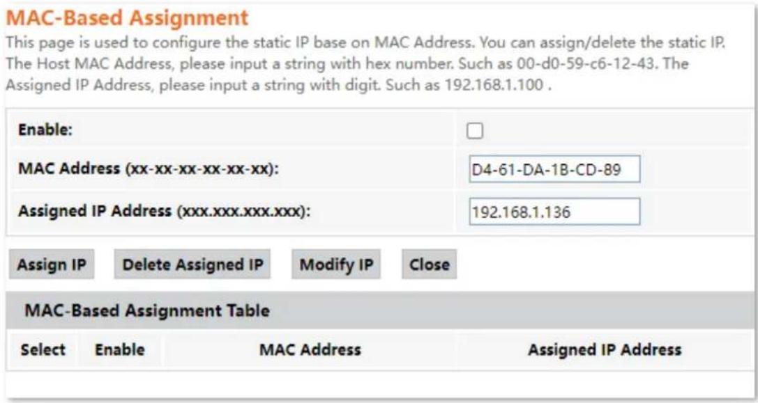
| MAC-Based Assignment | It is used to assign fixed IP addresses to certain LAN clients based on their MAC addresses. Devices with the MAC address connected to the ONT get the same IP address every time. Please note the format of the MAC address. Use “-” to separate every two characters in the MAC address. Please note the format of the MAC address. Use “-” to separate every two characters in the MAC address. |
Reserve IP addresses for certain devices
Scenario: You have an FTP server at home under the LAN of the ONT.
Requirement: You want to visit resources on the FTP server when you are not at home and avoid instability of services resulted from the dynamic IP address assigned by the ONT.
Solution: You can reserve a fixed IP address for the FTP server to reach the goal.
Assume that:
- Fixed IP address reserved for the FTP server: 192.168.1.136
- MAC address of the FTP server host: D4:61:DA:1B:CD:89
Configuring procedure:
Step 1 Log in to the web UI of the ONT.
Step 2 Choose Services > Service > DHCP.
Step 3 Click MAC-Based Assignment.
Step 4 Set MAC Address in the format of D4-61-DA-1B-CD-89.
Step 5 Enter 192.168.1.136 in Assigned IP Address.
Step 6 Click Assign IP.
---End
Now you can access resources on the FTP server free from the influence of the dynamic IP address.
7.1.2 Dynamic DNS
Overview
The Dynamic DNS (DDNS) maps the WAN IP address (changeable public IP address) of the ONT to a domain name for dynamic domain name resolution. This ensures proper operation of functions that involve the WAN IP address of the ONT, such as port forwarding and DMZ.
To access the configuration page, log in to the web UI of the ONT and choose Services > Service > Dynamic DNS.
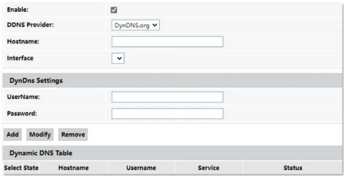
Parameter description
| Parameter | Description | |
| Enable | It specifies whether the rule takes effect after being added. | |
| DDNS Provider | It specifies the DDNS service provider. The ONT supports DynDNS.org and NO-IP.You need to register and purchase services from one of these service providers and use the parameters provided by the service provider to configure the function on the ONT. | |
| Hostname | It specifies the hostname registered with the DDNS service. | |
| Interface | It specifies the WAN interface on which the dynamic DNS rule takes effect. | |
| DynDns Settings | UserName | They specify the user name and password registered on a DDNS service provider for logging in to the DDNS service. |
| Password | ||
| Add/Modify/Remove | Add: It is used to add a new dynamic DNS rule.Modify: It is used to modify existing dynamic DNS rules.Remove: It is used to delete existing dynamic DNS rules. | |
Enable internet users to access LAN resources using a domain name
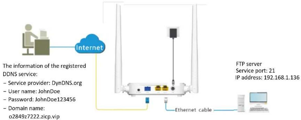
Scenario: You have set up an FTP server within your LAN.
Goal: Open the FTP server to internet users and enable yourself to access the resources of the FTP server from the internet using a domain name when you are not at home.
Solution: You can configure the DDNS plus port forwarding functions to reach the goal.
Assume that the information of the FTP server includes:
- IP address: 192.168.1.136
- Service port: 21
The information of the registered DDNS service:
– Service provider: DynDNS.org
- User name: JohnDoe
- Password: JohnDoe123
- Domain name: o2849z7222.zicp.vip

Please ensure that the ONT obtains a public IP address. This function may not work on a host with an IP address of a private network or an intranet IP address assigned by ISPs that start with 100. Common IPv4 addresses are classified into class A, class B and class C. Private IP addresses of class A range from 10.0.0.0 to 10.255.255.255. Private IP addresses of class B range from 172.16.0.0 to 172.31.255.255. Private IP addresses of class C range from 192.168.0.0 to 192.168.255.255.
Configuring procedure:
Step 1 Log in to the web UI of the ONT.
Step 2 Add a Dynamic DNS rule.
- Choose Services > Service > Dynamic DNS.
- Select Enable.
- Choose a service provider in DDNS Provider, which is DynDNS.org in this example.
- Enter the Hostname, which is o2849z7222.zicp.vip in this example.
- Select the WAN interface that the port forwarding rule applies to.
- Enter the user name and password in the DynDns Settings part, which are JohnDoe and JohnDoe123456 in this example.
- Click Add.
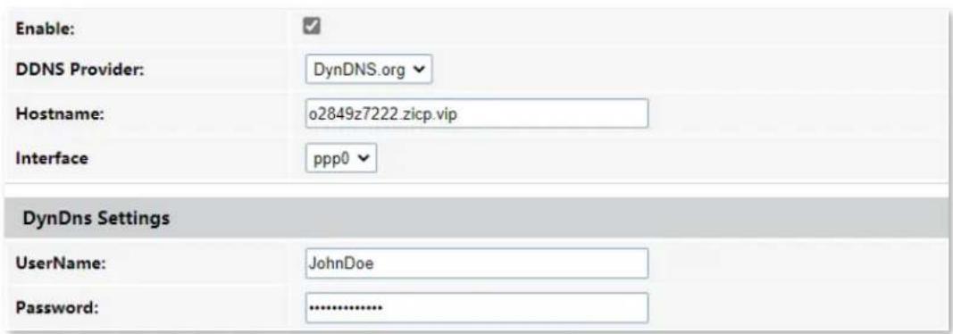
Step 3 Configure the port forwarding function (refer to port forwarding).
---End
After the configuration, users from the internet can access the FTP server by visiting "Intranet service application layer protocol name://Domain name". If the remote port number is not the same as the default intranet service port number, the accessing address should be: "Intranet service application layer protocol name://Domain name:Remote port number".
Services
In this example, the address is ftp://o2849z7222.zicp.vip.
To access the FTP server from the internet with a domain name:
Open the file explorer on a computer that can access the internet, and visit ftp://o2849z7222.zicp.vip.
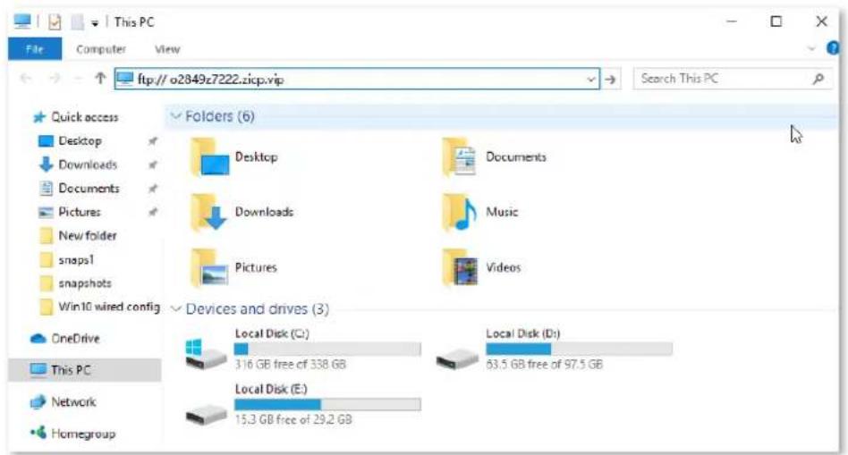
Enter the user name and password to access the resources on the FTP server.
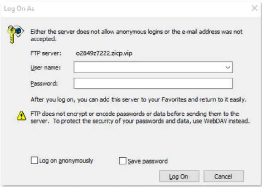

After the configuration, if internet users still cannot access the FTP server, try the following methods:
- Ensure that the local port number configured in the port forwarding function is the same as the intranet service port number set on the server.
- Close the firewall, antivirus software and security guards on the host of the FTP server and try again.
7.1.3 IGMP Proxy
IGMP proxy enables a device to issue IGMP host messages on behalf of its users, and reduces IGMP messages and the load for uplink device. The ONT with IGMP proxy enabled intercepts and processes the IGMP messages of its users, and then forward them to its uplink device. It assumes the role of router on the user side, queries user information regularly, and assumes the role of client on the network routing side, and sends the current user information to it when needed. Therefore, a multicast routing table is formed in the ONT with IGMP Proxy enabled.
To access the configuration page, log in to the web UI of the ONT and choose Services > Service > IGMP Proxy.

The IGMP proxy function can only be edited when there is at least one WAN connection with IGMP proxy enabled.

7.1.4 UPnP
UPnP is short for Universal Plug and Play. This function enables the ONT to open port automatically for UPnP-based programs. It is generally used for P2P programs, such as BitComet and AnyChat, and helps increase the download speed.
To access the configuration page, log in to the web UI of the ONT and choose Services > Service > UPnP.

7.2 Firewall
7.2.1 ALG
Application Layer Gateway (ALG) is a software component that manages specific application protocols such as Session Initiation Protocol (SIP) and File Transfer Protocol (FTP). The ALG acts as an intermediary between the internet and an application server and allows or denies traffic of certain types to the application server. It does this by intercepting and analyzing the specified traffic, allocating resources, and defining dynamic policies to allow traffic to pass through.
To access the configuration page, log in to the web UI of the ONT and choose Services > Firewall > ALG.
| ALG Type | ||
| FTP | ● Enable | ○ Disable |
| TFTP | ● Enable | ○ Disable |
| H323 | ● Enable | ○ Disable |
| RTSP | ● Enable | ○ Disable |
| L2TP | ● Enable | ○ Disable |
| IPSec | ● Enable | ○ Disable |
| SIP | ● Enable | ○ Disable |
| PPTP | ● Enable | ○ Disable |
Parameter description
| Parameter | Description |
| FTP | The File Transfer Protocol (FTP) is a standard network protocol used for the transfer of computer files between a client and server on a computer network.The users on LAN can share resources on the FTP server on WAN only when it is selected. |
| TFTP | The Trivial File Transfer Protocol (TFTP) is a simple file transfer protocol that allows a client to get a file from or put a file onto a remote host. |
| H323 | H.323 is a recommendation from the ITU Telecommunication Standardization Sector (ITU-T) that defines the protocols to provide audio-visual communication sessions on any packet network. The H.323 standard addresses call signaling and control, multimedia transport and control, and bandwidth control for point-to-point and multi-point conferences.The IP phone and network conference function can be used on the computers connected to the ONT only when this function is enabled. |
| RTSP | The Real Time Streaming Protocol (RTSP) is a network control protocol designed for use in entertainment and communications systems to control streaming media servers. The protocol is used for establishing and controlling media sessions between end points.The users on LAN can view videos on demand when this function is enabled. |
| L2TP | The Layer Two Tunneling Protocol (L2TP) is an extension of the Point-to-Point Tunneling Protocol (PPTP) used by an Internet Service Provider (ISP) to enable the operation of a Virtual Private Network (VPN) over the Internet.If you select L2TP protocol when you create a VPN connection on your computer in the LAN of the ONT, it takes effect only when this function is enabled. |
| IPSec | The Internet Protocol Security (IPsec) is a secure network protocol suite that authenticates and encrypts the packets of data to provide secure encrypted communication between two computers over an IP network. It is used in Virtual Private Networks (VPNs).If you select IPsec protocol when you create a VPN connection on your computer in the LAN of the ONT, it takes effect only when this function is enabled. |
| SIP | The Session Initiation Protocol (SIP) is a signaling protocol used for signaling and controlling multimedia communication sessions in applications of internet telephony for voice and video calls, in private IP telephone systems, in instant messaging over IP networks as well as mobile phone calling over LTE (VoLTE).The IP phone function can be used on the computers connected to the ONT only when this function is enabled. |
| PPTP | The Point-to-Point Tunneling Protocol (PPTP) is an obsolete method for implementing virtual private networks. PPTP has many well-known security issues.If you select the PPTP protocol when you create a VPN connection on your computer in the LAN of the ONT, it takes effect only when this function is enabled. |
7.2.2 IP/Port filtering
In this section, you can configure filtering rules to restrict certain types of data packets from passing through the ONT. The use of such filters can be helpful in securing or restricting your local network.
- LAN→WAN: By default, all outgoing traffic from LAN is allowed, but some can be blocked by specific filtering rules. Outgoing filtering rules can block outgoing traffic by some conditions.
- WAN→LAN: By default, all incoming traffic is blocked. However, some traffic can access by specific filtering rules. The incoming filtering rules allow traffic to pass in some conditions.
To access the configuration page, log in to the web UI of the ONT and choose Services > Firewall > IP/Port Filtering. The rules added are shown in the Current Filter Table.
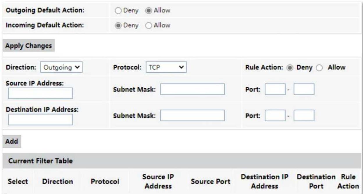
Parameter description
| Parameter | Description |
| Outgoing Default Action | They specify the default action for the outgoing (LAN WAN) or incoming (WAN LAN) data. |
| Incoming Default Action | Deny: Denies traffic which does not match the filter rule in the Current Filter Table.Allow: Allows traffic which does not match the filter rule in the Current Filter Table. |
| Direction | It specifies the forwarding direction of data to be filtered. |
| Protocol | It specifies the protocol adopted by packets to be filtered.TCP: TCP protocol.UDP: UDP protocol.ICMP: ICMP protocol.TCP/UDP: TCP protocol and UDP protocol.ANY: Any protocol. |
| Rule Action | It specifies whether to deny or allow the data to pass through.Deny: Packets that comply with the rule are denied, while others are treated with the default action.Allow: Only packets that comply with the rule are allowed, while others are treated with the default action. |
| Source IP Address | It specifies the source IP address of the packets. The settings of Source IP Address and Subnet Mask determine which computers are affected by this rule.When Direction is set to Outgoing, this parameter specifies the LAN computer's IP address to be affected.When Direction is set to Incoming, this parameter specifies the internet computer's IP address to be affected.When this parameter is left blank, all IP addresses are covered. |
| Subnet Mask | It specifies the subnet mask of the source IP address. |
| Port | It specifies the source port of the packets.The source port is only available for the TCP/UDP protocol. If ICMP or ANY is selected for Protocol, this field is not required.TIPSince the source port of the data packet is changeable, it is recommended that the port be set to 1 to 65535 or left blank. |
| Destination IP Address | It specifies the destination IP address of the packets. The settings of Destination IP Address and Subnet Mask determine which servers are affected by this rule.When Direction is set to Outgoing, this parameter specifies the internet server's IP address to be affected.When Direction is set to Incoming, this parameter specifies the LAN server's IP address to be affected.When this parameter is left blank, all IP addresses are covered. |
| Subnet Mask | It specifies the subnet mask of the destination IP address. The settings of Destination IP Address and Subnet Mask determine which servers are affected by this rule. |
| Port | It specifies the destination port of the packets. Its setting determines which services are affected by this rule.The destination port is only available for the TCP and UDP protocol. If ICMP or ANY is selected for Protocol, this field is not required. |
7.2.3 MAC filtering
Overview
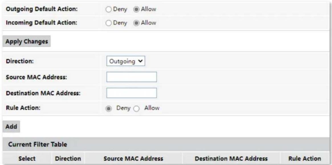
The MAC filtering function enables you to filter data packets from your local network to the internet to disallow clients with certain MAC addresses to access the internet and helps you to manage your network.
To access the configuration page, log in to the web UI of the ONT and choose Services > Firewall > MAC Filtering. The rule added are shown in Current Filter Table.
Services
Parameter description
| Parameter | Description |
| Outgoing Default Action | They specify the default action for the outgoing or incoming data.·Deny: Denies traffic which does not match the filter rule in the Current Filter Table. |
| Incoming Default Action | ·Allow: Allows traffic which does not match the filter rule in the Current Filter Table. |
| Direction | It specifies the forwarding direction of data to be filtered. |
| Source MAC Address | They specify the source and destination MAC addresses of data packets.You can only enter one source MAC address and destination MAC address in one MAC filtering rule. |
| Destination MAC Address | The MAC address cannot contain any special characters. An example in the correct format is cc3a61711b6e. |
| Rule Action | It specifies whether to deny or allow the data to pass through.·Deny: Packets that comply with the rule are denied, while others are treated with the default action.·Allow: Only packets that comply with the rule are allowed, while others are treated with the default action. |
Allow only specified devices to access the internet
Scenario: The Wi-Fi network at your home is misused by unknown users sometimes.
Goal: Only allow certain devices of family members to access the internet.
Solution: You can configure the MAC address filter function to reach the goal.
Assume that:
| Device | MAC address | Status |
| Your own phone | 8C:EC:4B:B3:04:93 | Connected |
| Family member's phone 1 | 94:C6:91:29:C2:12 | Disconnected |
| Family member's phone 2 | 98:9C:57:19:D0:1B | Disconnected |
Configuring procedure:
Step 1 Log in to the web UI of the ONT.
Step 2 Choose Services > Firewall > MAC Filtering.
Step 3 Set both Outgoing Default Action and Incoming Default Action to Deny.

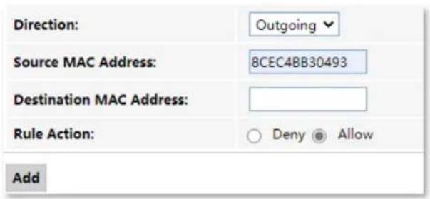
Step 4 Set Direction to Outgoing. Enter 8CEC4BB30493 in the Source MAC Address field, set Rule Action to Allow, and click Add.
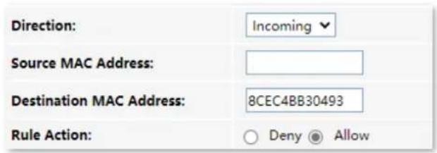
Step 5 Set Direction to Incoming. Enter 8CEC4BB30493 in the Destination MAC Address field, set Rule Action to Allow, and click Add.
Step 6 Repeat Step 4 to Step 5 to add the other two MAC addresses.
After the MAC addresses are added, they are displayed in Current Filter Table.
| Current Filter Table | ||||
| Select | Direction | Source MAC Address | Destination MAC Address | Rule Action |
| ☐ | Outgoing | 8c-ec-4b-b3-04-93 | ---- | Allow |
| ☐ | Outgoing | 94-c6-91-29-c2-12 | ---- | Allow |
| ☐ | Outgoing | 98-9c-57-19-d0-1b | ---- | Allow |
| ☐ | Incoming | ---- | 8c-ec-4b-b3-04-93 | Allow |
| ☐ | Incoming | ---- | 94-c6-91-29-c2-12 | Allow |
| ☐ | Incoming | ---- | 98-9c-57-19-d0-1b | Allow |
---End
In this example, after the configuration is completed, only the three devices added can access the internet through the ONT.
7.2.4 Port forwarding
Overview
By default, internet users cannot access any service on any of their local hosts. The port forwarding function enables you to open certain ports of a local host to internet users and allow them to access the corresponding services. This function can allow access and prevent the local network from being attacked at the same time.
To access the configuration page, log in to the web UI of the ONT and choose Services > Firewall > Port Forwarding. The rules added are shown in Current Port Forwarding Table.
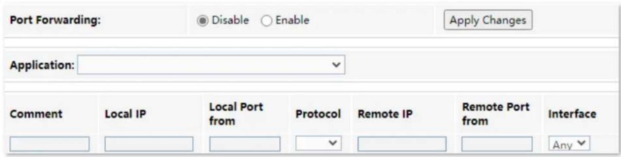
Parameter description
| Parameter | Description |
| Port Forwarding | It specifies whether to enable the port forwarding function. |
| Application | It includes some common services.When you choose a service from the list, some parameters of the rule are filled automatically, including Comment, Local Port from, Protocol and Remote Port from. |
| Comment | You can specify a comment for the rule for easy retrieval. |
| Local IP | It specifies the IP address of the LAN host which runs the service to be accessed. |
| Local Port from | It specifies a port or a range of ports used for the LAN service. |
| Protocol | It specifies the service protocol. Select Both if you are uncertain about the service type. |
| Remote IP | It specifies the IP address of the host which needs to access the local service.When it is left blank, users with any IP address can access the local server. |
| Remote Port from | It specifies a port or a range of ports that internet users use to access the local service. |
| Interface | It specifies the WAN interface through which internet users access the local service. |
Enable internet users to access local services
Scenario: You have set up an FTP server within your LAN.
Goal: Open the FTP server to internet users and enable family members who are not at home to access the resources of the FTP server from the internet.
Solution: You can configure the port forwarding function to reach the goal.
Assume that the information of the FTP server includes:
- IP address: 192.168.1.136
- MAC address: D4:61:DA:1B:CD:89
- Service port: 21
- The WAN IP address of the router: 102.33.66.88.

- Please ensure that the router obtains an IP address from the public network. This function may not work on a host with an IP address of a private network or an intranet IP address assigned by ISPs that start with 100. Common IPv4 addresses are classified into class A, class B and class C. Private IP addresses of class A range from 10.0.0.0 to 10.255.255.255. Private IP addresses of class B range from 172.16.0.0 to 172.31.255.255. Private IP addresses of class C range from 192.168.0.0 to 192.168.255.255.
- ISPs may block unreported web services to be accessed with the default port number 80. Therefore, when the default LAN port number is 80, please manually change it to an uncommon port number (1024–65535), such as 9999.
• The LAN port number can be different from the WAN port number.
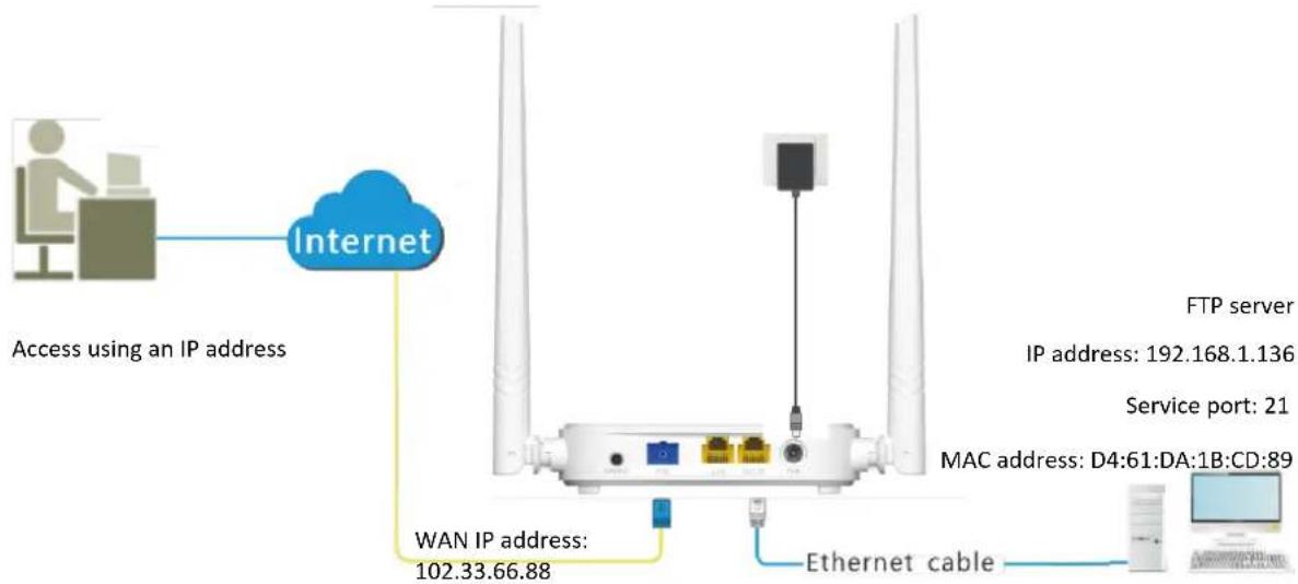
Configuring procedure:
Step 1 Log in to the web UI of the ONT.
Step 2 Add a port forwarding rule.
- Choose Services > Firewall > Port Forwarding.
- Set Port Forwarding to Enable, and click Apply Changes.
-
Select FTP Server from the Application drop-down list.
-
(Optional) Modify Comment for the rule, which is FTP server in this example.
-
Set Local IP, which is 192.168.1.136 in this example, and leave Remote IP blank.
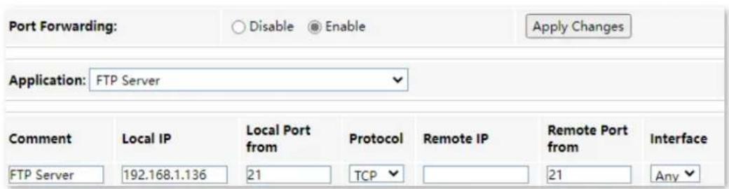
Step 3 Assign a fixed IP address to the host where the server locates.
- Choose Services > Service > DHCP.
- Click MAC-Based Management.
- Set MAC Address of the host of the server, which is D4-61-DA-1B-CD-89 in this example.
- Set Assigned IP Address for the server host, which is 192.168.1.136 in this example.

- Click Assign IP.
---End
Services
After the configuration, users from the internet can access the FTP server by visiting "Intranet service application layer protocol name://WAN IP address of the ONT". If the remote port number is different from the default intranet service port number, the visiting address should be: "Intranet service application layer protocol name://WAN IP address of the ONT:Remote port number". In this example, the address is "ftp://102.33.66.88". You can find the WAN IP address of the ONT in Device status.
To access the FTP server from the internet:
Open the file explorer on a computer that can access the internet, and visit ftp://102.33.66.88.
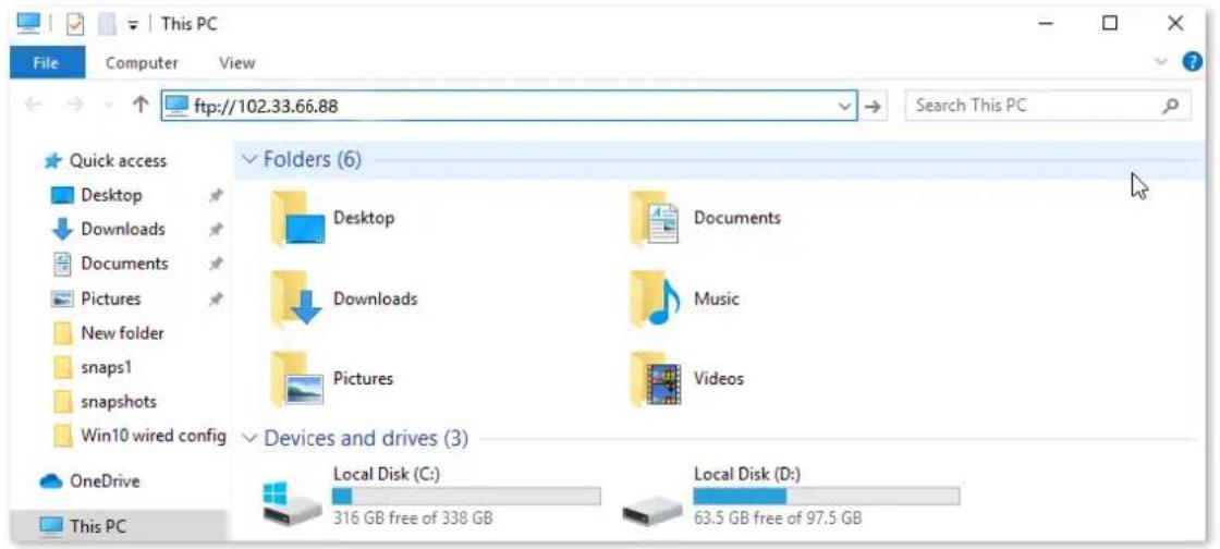
Enter the user name and password to access the resources on the FTP server.
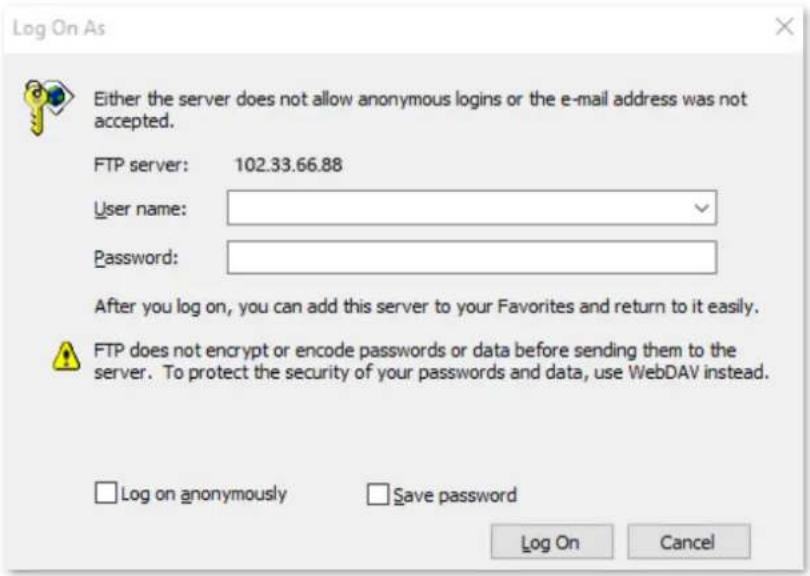
If you want to access the server within a LAN using a domain name, refer to the solution Dynamic DNS + Port Forwarding.

After the configuration, if internet users cannot access the FTP server, try the following methods:
- Ensure that the LAN port number configured in the port forwarding function is the same as the service port number set on the server.
- Close the firewall, antivirus software and security guards on the host of the FTP server and try again.
7.2.5 URL Blocking
Overview
The URL blocking function enables you to block LAN clients from accessing certain websites by specifying a Fully Qualified Domain Name (FQDN) or keyword.
To access the configuration page, log in to the web UI of the ONT and choose Services > Firewall > URL Blocking. The rule added are shown in the URL Blocking Table.
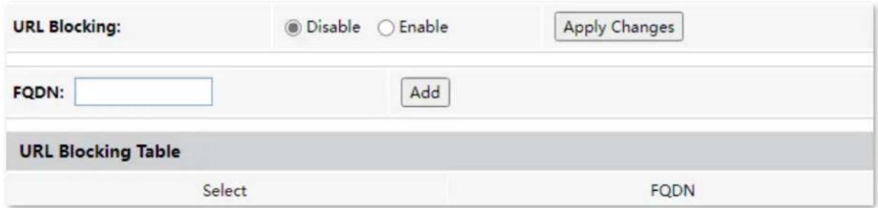
Parameter description
| Parameter | Description |
| URL Blocking | It specifies whether to enable the URL blocking function. |
| FQDN | It specifies the domain name that you want to block LAN clients from accessing.An FQDN, sometimes also referred to as an absolute domain name, is a domain name that specifies its exact location in the tree hierarchy of the Domain Name System (DNS). It specifies all domain levels, including the top-level domain and the root zone. |
Block clients from accessing certain websites
Assume that you use the ONT to provide internet access at your home. You want your children to focus on study rather than social media, such as Facebook, Twitter, or Instagram. You can use URL blocking to reach the goal.
Configuring procedure:
Step 1 Log in to the web UI of the ONT.
Step 2 Choose Services > Firewall > URL Blocking.
Step 3 Select Enable for URL Blocking, and click Apply Changes.
Step 4 Enter facebook in FQDN and click Add. Repeat this step for blocking Twitter and Instagram.

---End
After the configuration, Facebook, Twitter, and Instagram are not accessible through the ONT.
7.2.6 DMZ
Overview
A DMZ host on a LAN is free from restrictions in communicating with the internet. It is useful for getting better and smoother experiences in video conferences and online games. You can also set the host of a server within the LAN as a DMZ host when in need of accessing the server from the internet.
NOTE
- A DMZ host is not protected by the firewall of the router. Hackers may leverage the DMZ host to attack your LAN. Therefore, enable the DMZ function only when necessary.
- Hackers may leverage the DMZ host to attack the local network. Do not use the DMZ host function randomly.
• Security software, antivirus software, and the built-in OS firewall of the computer may cause DMZ function failures. Disable them when using the DMZ function. If the DMZ function is not required, you are recommended to disable it and enable your firewall, security, and antivirus software.
To access the configuration page, log in to the web UI of the ONT and choose Services > Firewall > DMZ.

Parameter description
| Parameter | Description |
| DMZ Host | It specifies whether to enable the DMZ host function. |
| DMZ Host IP Address | It specifies the IP address of the LAN host to be set as the DMZ host. |
Enable internet users to access LAN resources
Scenario: You have set up an FTP server within your LAN.
Goal: Open the FTP server to internet users and enable family members who are not at home to
access the resources of the FTP server from the internet.
Solution: You can configure the DMZ host function to reach the goal.
Assume that the information of the FTP server includes:
- IP address: 192.168.1.136
- MAC address: D4:61:DA:1B:CD:89
- Service port: 21
WAN IP address of the router: 102.33.66.88

Please ensure that the router obtains a public IP address public. This function may not work on a host with an IP address of a private network or an intranet IP address assigned by ISPs that start with 100. Common IPv4 addresses are classified into class A, class B and class C. Private IP addresses of class A range from 10.0.0.0 to 10.255.255.255. Private IP addresses of class B range from 172.16.0.0 to 172.31.255.255. Private IP addresses of class C range from 192.168.0.0 to 192.168.255.255.
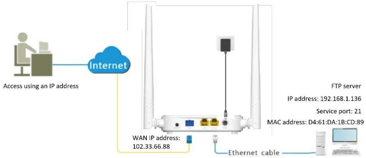
flowchart
graph TD
    A["User"] --> B["Access using an IP address"]
    B --> C["Internet"]
    C --> D["WAN IP address: 102.33.66.88"]
    D --> E["Ethernet cable"]
    E --> F["FTP server"]
    F --> G["IP address: 192.168.1.136"]
    F --> H["Service port: 21"]
    F --> I["MAC address: D4:61:DA:1B:CD:89"]
Configuring procedure:
Step 1 Log in to the web UI of the ONT.
Step 2 Set the server host as the DMZ host.
- Choose Services > Firewall > DMZ.
- Select Enable for DMZ Host.
- Enter the IP address of the server host, which is 192.168.1.136 in this example.
- Click Apply Changes.

Step 3 Assign a fixed IP address to the host where the server locates.
- Choose Services > Service > DHCP.
- Click MAC-Based Management.
- Enter the MAC Address of the host of the server, which is D4-61-DA-1B-CD-89 in this example.
- Enter the assigned IP Address for the server host, which is 192.168.1.136 in this example.
| MAC Address (xx-xx-xx-xx-xx-xx): | D4-61-DA-1B-CD-89 |
| Assigned IP Address (xxx.xxx.xxx.xxx): | 192.168.1.136 |
- Click Assign IP.
---End
After the configuration, users from the internet can access the FTP server by visiting "Intranet service application layer protocol name://WAN IP address of the ONT". If the intranet service port number is not the default number, the accessing address should be: "Intranet service application layer protocol name://WAN IP address of the ONT:Intranet service port number".

If the default intranet service port number is 80, please change the service port number to an uncommon one (1024–65535), such as 9999.
In this example, the address is "ftp://102.33.66.88". You can find the WAN IP address of the ONT in Device status.
To access the FTP server from the internet:
Open the file explorer on a computer that can access the internet, and visit ftp://102.33.66.88.
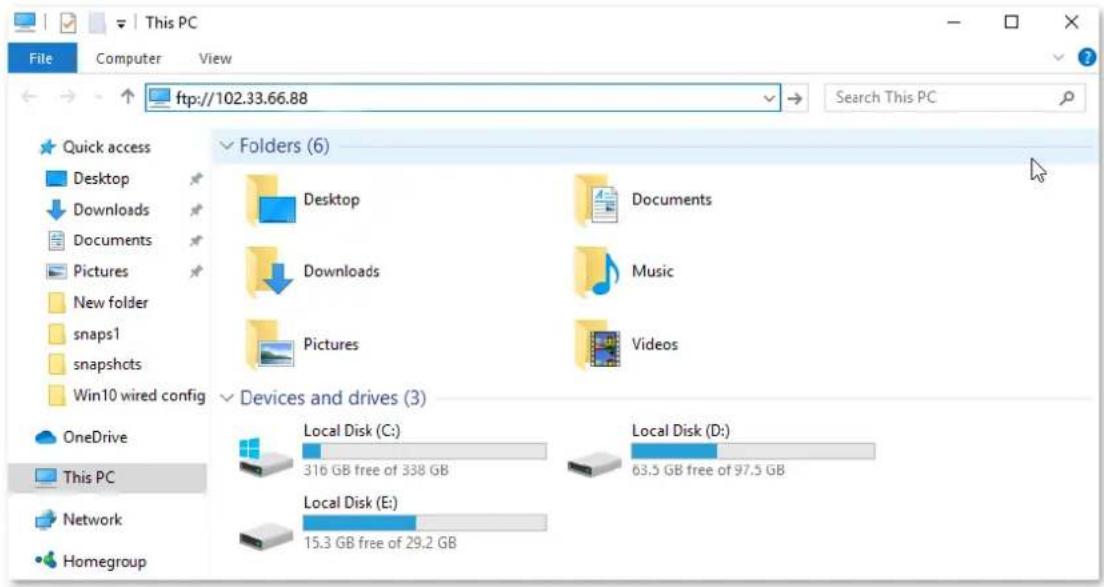
Enter the user name and password to access the resources on the FTP server.
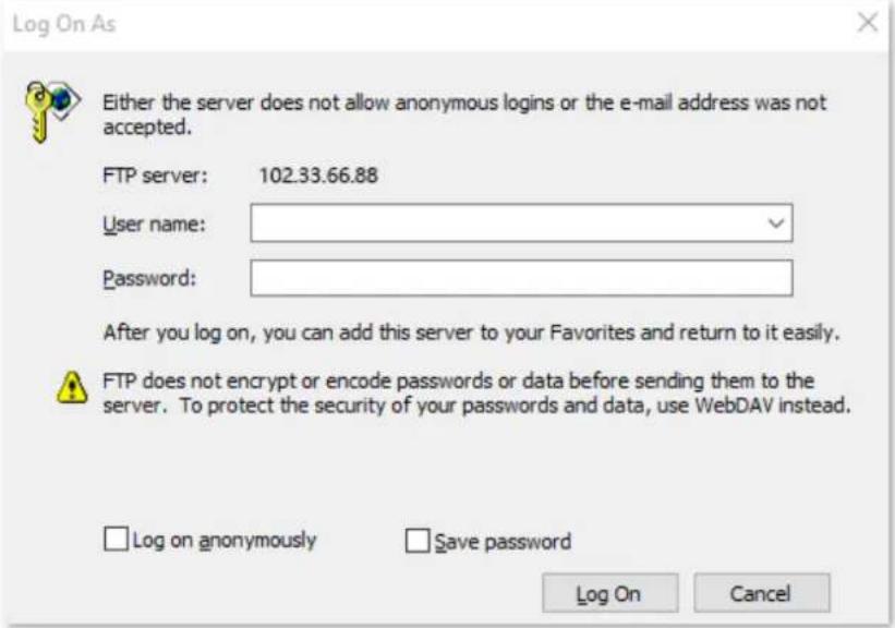
If you want to access the server within a LAN using a domain name, refer to the solution DMZ + Dynamic DNS.

After the configuration, if internet users still cannot access the FTP server, close the firewall, antivirus software and security guards on the host of the FTP server and try again.
8 Advance
8.1 Advanced settings
8.1.1 ARP table
On this page, you can view the IP address and MAC address of devices connected to the ONT in a wireless and wired manner.
To access the page, log in to the web UI of the ONT and choose Advance > Advance > ARP Table.
| IP Address | MAC Address |
| 192.168.1.2 | 8c-ec-4b-b3-04-92 |
8.1.2 Routing
Overview
On this page, you can add, modify, and delete static route rules. In addition, you can view the route table of the ONT.
Routing is the act of choosing an optimal path to transfer data from a source address to a destination address. A static route is a special route that is manually configured and has the advantages of simplicity, efficiency, and reliability. Proper static routing can reduce routing problems and overload of routing data flow, and improve the forwarding speed of data packets.
After the static route is established, all data whose destination address is the destination network of the static route are directly forwarded to the next hop through the static route interface.
To access the page, log in to the web UI of the ONT and choose Advance > Advance > Routing.
Advance
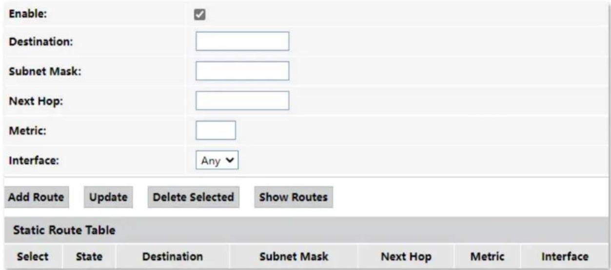
Parameter description
| Parameter | Description |
| Add Route | It is used to add a new static route rule. |
| Update | It is used to update your modification to an existing rule. |
| Delete Selected | It is used to delete the selected rule. |
| Show Routes | It is used to display the commonly used routes of the ONT. |
| Select | Select existing rules to update or delete them. |
| State | It specifies the status of a rule, including Enable and Disable. |
| Destination | It specifies the IP address of the destination network. |
| Subnet Mask | It specifies the subnet mask of the destination network. |
| Next Hop | It specifies the ingress IP address of the next hop route after the data packet exits from the WAN interface of the ONT. |
| Metric | It specifies the priority of the routing rule. The smaller the number, the higher the priority.When the destination networks of two rules are the same, packets will be forwarded according to the rule with smaller metric. |
| Interface | It specifies the interface of the ONT that the packet exits from. |
Add a new static route rule
Step 1 Log in to the web UI of the ONT.
Step 2 Choose Advance > Advance > Routing.
Step 3 Select Enable as required.
Step 4 Set Destination, Subnet Mask, Next Hop, Metric, and Interface.
Step 5 Click Add Route.
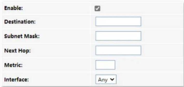
---End
After the configuration succeeds, the static rule will be displayed in Static Route Table.
Modify a static rule
Step 1 Log in to the web UI of the ONT.
Step 2 Choose Advance > Advance > Routing.
Step 3 Select a static route rule, and it will appear in the configuring part.
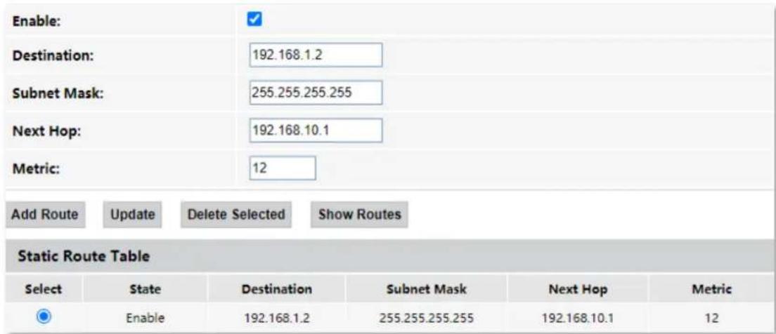
Step 4 Modify the parameters of the rule as required.
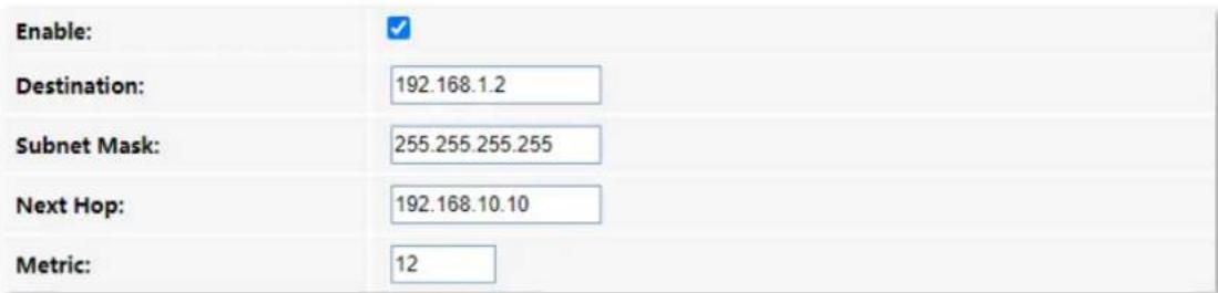
Step 5 Click Update.
---End
After the configuration succeeds, the updated parameters of the static rule will be displayed in Static Route Table.
| Static Route Table | |||||
| Select | State | Destination | Subnet Mask | Next Hop | Metric |
| Og | Enable | 192.168.1.2 | 255.255.255.255 | 192.168.10.10 | 12 |
Delete an existing rule
To delete an existing rule, select the rule in Static Route Table and click Delete Selected.
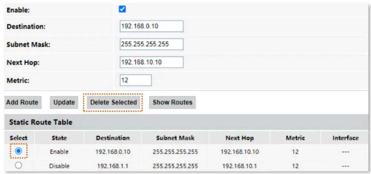
Show commonly used routes
Click Show Routes, and you will find the commonly used routes in the prompt window.
| Destination | Subnet Mask | Next Hop | Metric | Interface |
| 0.0.0.0 | 0.0.0.0 | * | 0 | ppp0 |
| 10.11.122.1 | 255.255.255.255 | * | 0 | ppp0 |

- The route with 0.0.0.0 as both destination and subnet mask is the default route. When no perfectly matched route is found for a packet, the packet will be forwarded through the default route.
0.0.0.0 as the next hop indicates that the ONT is directly connected to the destination network.
8.1.3 SNMP
The Simple Network Management Protocol (SNMP) is the most widely used network management protocol in TCP/IP networks. SNMP enables you to remotely manage all your network devices compliant with this protocol, such as monitoring the network status, changing network device settings, and receiving network event alarms.
SNMP allows automatic management of devices from various vendors regardless of physical differences among the devices.
SNMP management framework
The SNMP management framework consists of the SNMP manager, SNMP agent, and Management Information Base (MIB).
- SNMP manager: It is a system that controls and monitors network nodes using the SNMP protocol. The SNMP manager most widely used in network environments is Network Management System (NMS). An NMS can be a dedicated network management server, or an application that implements management functions in a network device.
- SNMP agent: It is a software module in a managed device. The module is used to manage data about the device and report the management data to an SNMP manager.
- MIB: It is a collection of managed objects. It defines a series of attributes of managed objects, including names, access permissions, and data types of objects. Each SNMP agent has its MIB. An SNMP manager can read and/or write objects in the MIB based on the permissions assigned to the SNMP manager.
SNMP operations
There are mainly three operations based on SNMP:
- Get: The SNMP manager sends a request to retrieve the value of a variable or list of variables.
- Set: The SNMP manager sends a request to change the value of a variable or list of variables.
- Trap: The SNMP agent notifies the SNMP manager of significant events by an unsolicited SNMP message.
An SNMP manager manages SNMP agents in an SNMP network. The SNMP manager exchanges management information with the SNMP agents using the SNMP protocol. The ONT functions as an SNMP agent.
The ONT is compatible with SNMP V1 and SNMP V2C and adopts the community authentication mechanism.
To access the page, log in to the web UI of the ONT and choose Advance > Advance > SNMP.
| SNMP: | ○ Disable ○ Enable |
| System Description: | System Description |
| System Contact: | System Contact |
| SystemName: | HG9 |
| System Location: | System Location |
| System Object ID: | 1.3.6.1.4.1.16972 |
| Trap IP Address: | 192.168.1.254 |
| Community name (read-only): | public |
| Community name (write-only): | public |
Parameter description
| Parameter | Description |
| SNMP | It specifies whether to enable the SNMP agent function. |
| System Description | It specifies a description of the ONT, which can be anything you like and is used for identification. |
| System Contact | It specifies the contact information of the ONT. |
| SystemName | It specifies the name of ONT. |
| System Location | It specifies the place where the ONT is located. |
| System Object ID | It specifies the object ID of the ONT in the MIB, which can be used by the SNMP manager to identify and manage the ONT. |
| Trap IP Address | It specifies the destination IP address of the SNMP trap. Make sure that the ONT and the SNMP manager are reachable to each other. |
| Community name (read-only) | They specify the community names which act as passwords for the interaction between the SNMP manager and SNMP agent. |
| Community name (write-only) | Community name (read-only): It is used to authenticate the Get request.Community name (write-only): It is used to authenticate the Set request. |
8.2 IPv6 settings
The ONT supports both IPv4 and IPv6 for internet access. In this module, you can enable and disable IPv6 of the ONT, and perform other IPv6-related configurations on the ONT.
8.2.1 IPv6 status
On this page, you can enable or disable the IPv6 function of the ONT.
To access the page, log in to the web UI of the ONT and choose Advance >IPv6 >IPv6 Enable/Disable. Select Enable or Disable and click Apply Changes.
IPv6:
○ Disable
◎ Enable
8.2.2 RADVD
The Router Advertisement Daemon (RADVD) is used by system administrators in stateless auto-configuration methods of network hosts on IPv6 networks.
When IPv6 hosts configure their network interfaces, they broadcast Router Solicitation (RS) requests onto the network to discover available devices. The RADVD software answers requests with Router Advertisement (RA) messages. In addition, RADVD periodically broadcasts RA packets to the attached link to update network hosts.
To access the page, log in to the web UI of the ONT and choose Advance > IPv6 > RADVD.
| RADVDEnabled: | ○ off ● on |
| MaxRtrAdvInterval: | 600 |
| MinRtrAdvInterval: | 198 |
| AdvManagedFlag: | ○ off ● on |
| AdvOtherConfigFlag: | ○ off ● on |
| Prefix Mode: | Manual ▼ |
| Prefix: | 3ffe:501:ffff:100:: |
| Prefix Length: | 64 |
| AdvValidLifetime: | 2592000 |
| AdvPreferredLifetime: | 604800 |
| Enable ULA: | ○ off ● on |
| ULA Prefix: | fc01:: |
| ULA Prefix Len: | 64 |
| ULA Prefix Valid Time: | 2592000 |
| ULA Prefix Preferred Time: | 604800 |
Parameter description
| Parameter | Description |
| MaxRtrAdvInterval | They specify the Maximum and Minimum Router Advertisement Intervals.They are the intervals between each router advertisement message. The router sends these messages periodically. The actual interval used is randomly selected from a value between the minimum and maximum values. |
| MinRtrAdvInterval | |
| AdvManagedFlag | They specify the Advertisement Managed Flag and Advertisement Other Configuration Flag.Advertisement Managed Flag: This flag indicates that hosts retrieve managed IPv6 addresses from a DHCPv6 server for their interfaces.Advertisement Other Configuration Flag: This flag indicates that hosts use SLAAC to generate their IPv6 address and obtain other configuration information using DHCPv6, such as DNS information. |
| AdvOtherConfigFlag | |
| Prefix Mode | It specifies the configuring mode of the prefix which is assigned to the IPv6 host, includingAutoand Manual.Auto: The ONT automatically assigns a prefix to the IPv6 host.Manual: You need to set the prefix manually. |
| Prefix | They specify the prefix information included in the RA message to hosts for generating their IPv6 address. |
| Prefix Length | |
| AdvValidLifetime | They specify the Advertisement Valid Lifetime and Advertisement Preferred Lifetime.When the preferred lifetime expires, the use of the prefix is not encouraged, but not prohibited. When the valid lifetime expires, the prefix becomes invalid. |
| AdvPreferredLifetime | The valid lifetime must be greater than or equal to the preferred lifetime. |
| Enable ULA | It specifies whether to enable the Unique Local Address (ULA).The purpose of ULA resembles that of the private network address in IPv4. It is only used within the private network and increases stability for the IPv6 host and its use of services. |
| ULA Prefix | They specify the ULA prefix information advertised by the ONT to hosts for generating unique local addresses. |
| ULA Prefix Len | |
| ULA Prefix Valid Time | They specify the valid lifetime and preferred lifetime of ULA prefix. |
| ULA Prefix Preferred Time | When the preferred lifetime expires, the use of the ULA prefix is not encouraged, but not prohibited. When the valid lifetime expires, the ULA prefix becomes invalid. |
| The valid lifetime must be greater than or equal to the preferred lifetime. |
8.2.3 DHCPv6
IPv6 hosts may automatically generate IP addresses internally using Stateless Address Autoconfiguration (SLAAC), or they may be assigned configuration with Dynamic Host Configuration Protocol version 6 (DHCPv6). When the DHCPv6 server is enabled, the ONT can assign IPv6 hosts with IP addresses, IP prefixes and other configurations required for IPv6 internet access.
To access the page, log in to the web UI of the ONT and choose Advance >IPv6 >DHCPv6.
| DHCPv6 Mode: | ○NONE ● DHCPServer | |
| DHCPv6 Server Type: | ○Auto ● Manual | |
| Enable the DHCPv6 Server if you are using this device as a DHCPv6 server. This page lists the IP address pools available to hosts on your LAN. The device distributes numbers in the pool to hosts on your network as they request Internet access. | ||
| IP Pool Range: | 3ffe:501:ffff:100::10 - 3ffe:501:ffff:100::100 Show Client | |
| Prefix Length: | 64 | |
| Valid Lifetime: | 20000 seconds | |
| Preferred Lifetime: | 16000 seconds | |
| Renew Time: | 5000 seconds | |
| Rebind Time: | 10000 seconds | |
| Client DUID: | 00:01:00:01:00:04:93:e0:00:00:00:00:a2:a2 | |
| Apply Changes | ||
| Domain: | ||
| Domain Search Table | ||
| Select Domain | ||
| Delete Selected Delete All | ||
| Name Server IP: | ||
| Name Server Table | ||
| Select Name Server | ||
Parameter description
| Parameter | Description |
| DHCPv6 Mode | You can select a DHCPv6 server mode or disable it.NONE: The DHCPv6 server of the ONT is disabled.DHCPServer: The DHCPv6 server of the ONT is enabled. |
| DHCPv6 Server Type | It specifies whether the DHCPv6 Server is configured automatically or manually.DHCPServer(Manual): You need to define the IP address pool, prefix length and other required parameters for IPv6 addresses to be assigned to IPv6 hosts.DHCPServer(Auto): The ONT defines the IPv6 addresses to be assigned to the IPv6 host automatically. |
| IP Pool Range | It specifies the IP address range within which the ONT can assign IPv6 addresses to the IPv6 host. |
| Show Client | It shows information of the active DHCPv6 clients, including:IP Address: It specifies the IP address assigned to the DHCP leased client.DUID: It specifies the DHCP Unique Identifier (DUID) of the DHCP leased client.Expired Time (sec): It specifies the time expired for the DHCP leased client. |
| Prefix Length | It specifies the length of IPv6 prefix. |
| Valid Lifetime | They specify the valid lifetime and preferred lifetime of the IPv6 address assigned to IPv6 hosts.When the preferred lifetime expires, communication using the IPv6 address is not encouraged, but allowed. When the valid lifetime expires, the IPv6 address becomes invalid. |
| Preferred Lifetime | |
| Renew Time | It specifies the time before expiration when the host is expected to contact the DHCPv6 server that did the assignment to renew the lifetimes of the addresses assigned to the client. |
| Rebind Time | It specifies the new valid time after the IPv6 address is renewed. |
| Client DUID | It specifies the DHCP Unique Identifier (DUID) assigned to clients.The DUID is used by a client to get an IP address from a DHCPv6 server, and the server compares the DUID with its database and delivers configuration data (such as the address and DNS servers) to the client. |
| Domain | It is used to configure the domain. |
| Domain Search Table | It displays all domain settings. |
| Name Server IP | You can add a DNS server address to obtain DNS information for address resolution. |
| Name Server Table |
9 Diagnostics
9.1 Overview
The ONT provides connectivity diagnosis tools, which include Ping and Tracert. You can use these tools to test the connectivity to the internet, a certain IP address or domain name.
- Ping: It is a utility that helps to check if an IP address or domain name is accessible or not. Ping works by sending a packet to the specified address and waits for the reply. It also measures round trip time and reports errors.
Tracert: It is a utility that traces a packet from your computer to the host, and will also show the number of steps (hops) required to reach there, along with the time by each step.
To access the page, log in to the web UI of the ONT and choose Diagnostics. Both tools include IPv4 (Ping/Tracert) and IPv6 (Ping6/Tracert6) versions. The IPv4 version is used for illustration.
Ping

Parameter description
| Parameter | Description |
| Host Address | It specifies the IP address or domain name whose connectivity with the ONT is to be diagnosed. |
| WAN Interface | It specifies the WAN interface through which the packet for diagnosis is forwarded. |
Tracert
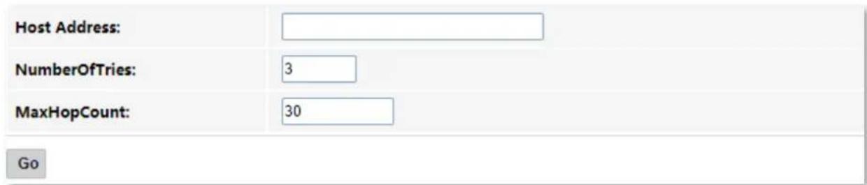
Parameter description
| Parameter | Description |
| Host Address | It specifies the IP address or domain name of the tracert target. |
| Number Of Tries | It specifies the maximum number of times that the host tries to reach the host address.If all the attempts fail, it denotes network congestion and a reason for slow loading Web pages and dropped connections. |
| Max HopCount | It specifies the hops of the packet for diagnosis.When a packet cannot reach the destination and expires at an intermediate step, that node returns the packet and identifies itself. It denotes network congestion and a reason for slow loading web pages and dropped connections. |
9.2 Execute Ping to test connectivity
Step 1 Log in to the web UI of the ONT.
Step 2 Choose Diagnostics > Ping.
Step 3 Enter the IP address or domain name in Host Address, such as www.google.com.
Step 4 Choose any interface from WAN Interface.
Step 5 Click Go.

Wait a moment. The result appears when the diagnosis finishes.
---End
9.3 Execute Traceroute to test routing
Step 1 Log in to the web UI of the ONT.
Step 2 Choose Diagnostics > Tracert.
Step 3 Enter the IP address or domain name in Host Address, such as www.google.com.
Step 4 Specify the number of attempts in Number Of Tries.
Step 5 Specify the number of hops in Max HopCount.
Step 6 Click Go.

Wait a moment. The result appears when the diagnosis finishes.
---End
9.4 Manual inform report
On this page, you can manually inform reports to the Auto-Configuration Server (ACS). To access this page, log in to the web UI of the ONT and choose Diagnostics > Inform report.
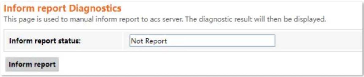
10 Admin
10.1 GPON/EPON settings
On this page, you can register your ONT for internet access.
The ONT may register itself automatically after you connect a fiber cord to it and power it on. Under some circumstances, you may need to manually register the ONT with parameters provided by your ISP on this page.
To access the page, log in to the web UI of the ONT and choose Admin > GPON Settings (or EPON Settings). Enter the parameters provided by your ISP and click Apply Changes to register the ONT.
You can view the registration status of the ONT on the PON status page.
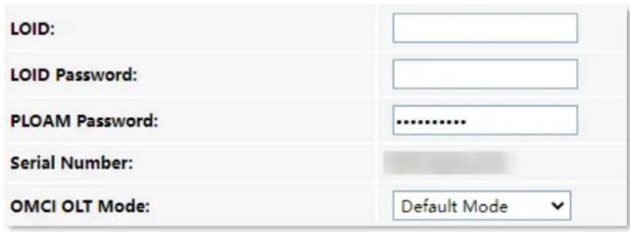
10.2 OMCI information
ONU Management Control Interface (OMCI) defines a mechanism and message format that is used by the Optical Line Termination (OLT) to configure, manage, and monitor ONTs.
To access the page, log in to the web UI of the ONT and choose Admin > OMCI Information. You can click Refresh to update the information.
| OMCI software version 1: | v1.0.0 |
| OMCC version: | 0x80 |
| Traffic Management option: | 2 |
| CWMP Product Class: | HG3V1.0 |
| HW version: | v1.0 |
10.3 Commit/Reboot
This page is used to commit any configuration changes you have made and reboot the ONT to put the changes into effect. Click Commit and Reboot to save settings and reboot the ONT.
To access the page, log in to the web UI of the ONT and choose Admin > Commit/Reboot.
| Commit and Reboot: | Commit and Reboot |
10.4 Backup/Restore
On this page, you can back up the configuration of the ONT, restore the configuration from a backup file, and reset the ONT.
To access the page, log in to the web UI of the ONT and choose Admin > Backup/Restore.

10.4.1 Back up the configuration of the ONT
You can back up the configuration of the ONT at a certain time for future restoration after you change the settings or reset the ONT.
Configuring procedure:
Step 1 Log in to the web UI of the ONT.
Step 2 Choose Admin > Backup/Restore.
Step 3 Click Backup....
Backup Settings to File:
Backup...
The configuration file (config.xml) is automatically downloaded to the local host.
---End
10.4.2 Restore previous configuration of the ONT
You can restore the previous configuration of the ONT using the backup file that you have downloaded.
Configuring procedure:
Step 1 Log in to the web UI of the ONT.
Step 2 Choose Admin > Backup/Restore.
Step 3 Click Choose File, and select the configuration file.

Restore Settings from File:
Choose File config.xml
Restore
The ONT reboots to enable the configuration to take effect.
---End
10.4.3 Reset the ONT
When the ONT malfunctions and you cannot find a solution, you can try to reset the ONT. If your ISP has preset the ONT, the ONT will be restored to the configurations preset by the ISP. Otherwise, the ONT will be restored to factory settings.

Resetting the ONT will clear all previous personalized configurations. It is recommended to back up the configuration of the ONT in advance.
Configuring procedure:
Step 1 Log in to the web UI of the ONT.
Step 2 Choose Admin > Backup/Restore.
Step 3 Click Reset.
Reset Settings to Default:
Reset
The ONT starts rebooting. Wait until it finishes rebooting, and then you can log in to the ONT again and perform settings.
---End
10.5 Password
On this page, you can change the login password for the ONT. The default login user name and password are admin. You can only change the password, and the original password is required during the process.
Configuring procedure:
Step 1 Log in to the web UI of the ONT.
Step 2 Choose Admin > Password.
Step 3 Enter the original password in Old Password.
Step 4 Enter your new password in New Password and Confirmed Password.
Step 5 Click Apply Changes.

The following message is displayed, indicating that the password is changed successfully.

---End
10.6 Firmware upgrade
To get new features and improve performance and operating stability, you can upgrade the firmware of the ONT when a new version is available.
Configuring procedure:
Step 1 Go to www.tendacn.com. Download an applicable firmware of the ONT to your local computer and unzip it.
Step 2 Log in to the web UI of the ONT.
Step 3 Choose Admin > Firmware Upgrade.
Step 4 Click Choose File, and select the upgrade file.
Step 5 Click Upgrade.

The ONT reboots automatically.
---End
10.7 ACL
Access Control List (ACL) is a collection of permit and deny rules that ensure security by blocking unauthorized users from and allowing authorized users to access ONT.
To access the page, log in to the web UI of the ONT and choose Admin > ACL.
| ACL Capability: | ○ Disable ● Enable | Apply Changes |
| Enable: | ✓ | |
| Interface: | LAN ▼ | |
| Start IP Address: | ||
| End IP Address: |
| ServiceName | LAN |
| TELNET | |
| HTTP | |
| HTTPS | |
| PING |
Add
| ACL Table | |||||
| Select | State | Interface | IP Address | Services | Port |
| □ | Enable | LAN | 0.0.0.0 | web,https,snmp,ping | 80,443,161,162,-- |
| □ | Enable | LAN | 192.168.1.2-192.168.1.254 | telnet,ping | 23,-- |
Parameter description
| Parameter | Description |
| ACL Capability | It specifies whether to enable the ACL function of the ONT. |
| Enable | It specifies the control mode of the function.When Enableis selected, traffic that meets the criteria of the rule can pass through the specified port of the ONT.When Enableis deselected, traffic that meets the criteria of the rule is discarded at the specified port of the ONT. |
| Interface | It specifies the interface that the access control rule applies to, including LAN and WAN.LAN: The ONT checks traffic from the LAN side according to the rule and decides to pass it or discard it.WAN: The ONT checks traffic from the WAN side according to the rule and decides to pass it or discard it. |
| Start IP Address | They specify the IP address range or a certain IP address that is controlled by the rule. |
| End IP Address | |
| ServiceName | It specifies the protocol adopted by the traffic, or the types of traffic.TELNET: Telnet is a protocol that provides a command line interface for communication with a remote device or server, sometimes employed for remote management but also for initial device setup like network hardware.HTTP: Hypertext Transfer Protocol (HTTP) is an application protocol and the foundation of data communication for the World Wide Web, where hypertext documents include hyperlinks to other resources that the user can easily access.HTTPS: Hypertext Transfer Protocol Secure (HTTPS) is an extension of HTTP. SNMP is used for secure communication over a computer network, and is widely used on the Internet.PING: Ping is a computer network administration software utility used to test the reachability of a host on an IP network. |
| WAN | It specifies the interface to which the rule applies. It changes as you choose an interface. |
| LAN | |
| ACL Table | It displays all the ACL rules that are added. |
| Select | It is used to select multiple ACL rules. |
| State | It specifies the control mode of the rule. If you deselect Enable when setting an ACL rule, the State shows Disable. |
| Interface | It specifies the interface that the access control rule applies to, including LAN and WAN. |
| IP Address | It specifies the IP address range or a certain IP address that is controlled by the rule. |
| Services | It specifies the protocols adopted by the traffic, or the types of traffic. |
| Port | It specifies the default ports adopted by the corresponding services. |
10.8 Time Zone
On this page, you can change the system time of the ONT, or enable the ONT to update its system time with the Simple Network Time Protocol (SNTP) server.
To access the page, log in to the web UI of the ONT and choose Admin > Time Zone.
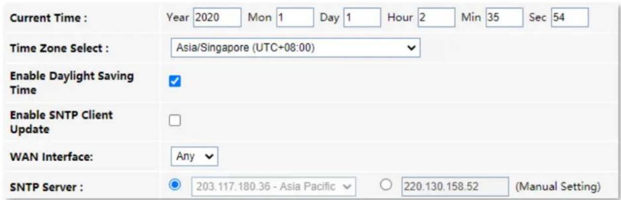
Parameter description
| Parameter | Description |
| Current Time | It specifies the current system time of the ONT. You can change it manually. |
| Time Zone Select | It specifies the time zone where the ONT locates. |
| Enable Daylight Saving Time | Daylight Saving Time (DST) is the practice of advancing clocks during warmer months so that darkness falls later each day according to the clock.With it is enabled, the ONT sets the time forward by one hour in the spring ("spring forward") and set the time back by one hour in autumn ("fall back") to return to standard time. In other words, there is one 23-hour day in late winter or early spring and one 25-hour day in the autumn. |
| Enable SNTP Client Update | It specifies whether to enable automatic update of system time through synchronization with SNTP server.The SNTP is a time synchronization protocol of the TCP/IP protocol family. It is based on the connectionless User Datagram Protocol (UDP) and can be used on all supporting devices to synchronize system time in IP networks. |
| WAN Interface | It specifies the interface through which the ONT updates its system time with the SNTP server. |
| SNTP Server | You can choose a preset SNTP server, or manually set the IP address for updating system time. |
10.9 TR-069
The Customer Premise Equipment (CPE) WAN Management Protocol (TR-069) allows an ACS (Auto-Configuration Server) to perform auto-configuration, provision, collection, and diagnostics to the ONT from the internet. Generally, it is used by the ISP to manage the ONT.
To access the page, log in to the web UI of the ONT and choose Admin > TR-069.
| TR069 Daemon: | ● Enabled ○ Disabled |
| Enable CWMP Parameter: | ● Enabled ○ Disabled |
| ACS | |
| URL: | |
| UserName: | cpe |
| Password: | ... |
| Periodic Inform: | ○ Disabled ● Enabled |
| Periodic Inform Interval: | 43200 |
| Connection Request | |
| Authentication: | ○ Disabled ● Enabled |
| UserName: | |
| Password: | |
| Path: | /tr069 |
| Port: | 7547 |
Parameter description
| Parameter | Description | |
| TR069 Daemon | It specifies whether to enable the TR069 function. | |
| Enable CWMP Parameter | It specifies whether to enable the CPE WAN management protocol. | |
| ACS | URL | It specifies the URL of the ACS. |
| UserName | They specify the user name and password used to authenticate the ONT when the ONT connects to the ACS using the CPE WAN management protocol. | |
| Password | ||
| Periodic Inform | It is used to enable or disable the ONT to periodically inform ACS. | |
| Periodic Inform Interval | It specifies the interval that the ONT to inform the ACS. | |
| Parameter | Description | |
| Connection Request | Authentication | It specifies whether to authenticate the connection request sent by the ACS. |
| UserName | They specify the user name and password used to authenticate the ACS when it sends the connection request to the CPE. | |
| Password | ||
| Path | It specifies the path used to receive the connection request sent by the ACS. Keep the default value if you are not sure. | |
| Port | It specifies the port used to receive the connection request sent by the ACS. | |
10.10 Logout
To access the page, choose Admin > Logout.
You can log out of the web UI of the ONT by clicking Logout on this page, or click Logout at the upper-right corner of the web UI.
Logout
This page is used to logout from the Device.
Logout
11 Statistics
In this part, you can view the packet statistics of the ports and interfaces of the ONT.
Interface statistics
This page displays the received and transmitted packets statistics, including the received packets (Rx pkt), received packets error (Rx err), dropped received packets (Rx drop), transmitted packets (Tx pkt), transmitted packets error (Tx err), dropped transmitted packets (Tx drop).
To access the page, log in to the web UI of the ONT and choose Statistics > Interface.
| Interface | Rx pkt | Rx err | Rx drop | Tx pkt | Tx err | Tx drop |
| LAN1 | 0 | 0 | 0 | 0 | 0 | 0 |
| LAN2 | 32421 | 2 | 0 | 23607 | 0 | 0 |
| wlan0 | 175248 | 0 | 0 | 0 | 0 | 0 |
| nas0_0 | 0 | 0 | 0 | 0 | 0 | 0 |
PON statistics
The page displays the data statistics transmitted and received through the PON port.
To access the page, log in to the web UI of the ONT and choose Statistics > PON Statistics.
| Bytes Sent: | 0 |
| Bytes Received: | 0 |
| Packets Sent: | 0 |
| Packets Received: | 0 |
| Unicast Packets Sent: | 0 |
| Unicast Packets Received: | 0 |
| Multicast Packets Sent: | 0 |
| Multicast Packets Received: | 0 |
| Broadcast Packets Sent: | 0 |
| Broadcast Packets Received: | 0 |
| FEC Errors: | 0 |
| HEC Errors: | 0 |
| Packets Dropped: | 0 |
| Pause Packets Sent: | 0 |
| Pause Packets Received: | 0 |
Appendixes
A.1 Configure the computer to obtain an IPv4/IPv6 address automatically
Perform the configuration procedure in Windows 10, Windows 8 and Windows 7 as required. A computer installed with a wired network adapter is used as an example to describe the procedure. The procedures for configuring computers installed with WiFi network adapters are similar.
A.1.1 Windows 10
Step 1 Click in the bottom right corner of the desktop and choose Network settings.

Step 2 Click Change adapter options.
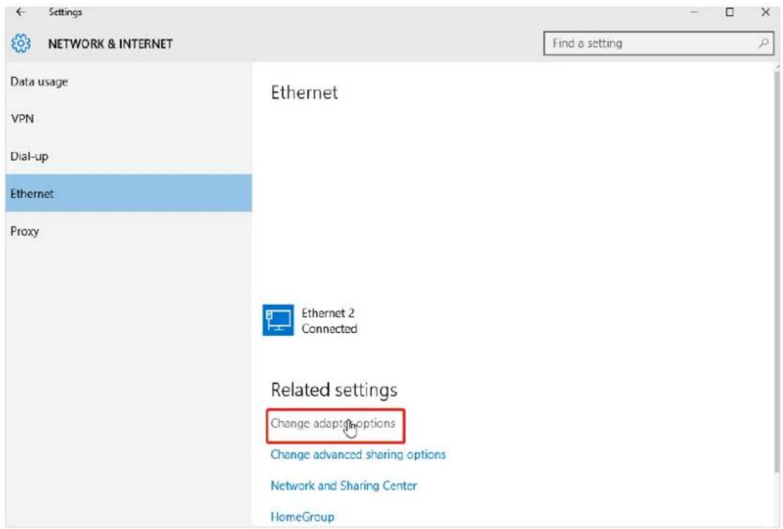
Step 3 Right-click on the connection in use, and then click Properties.
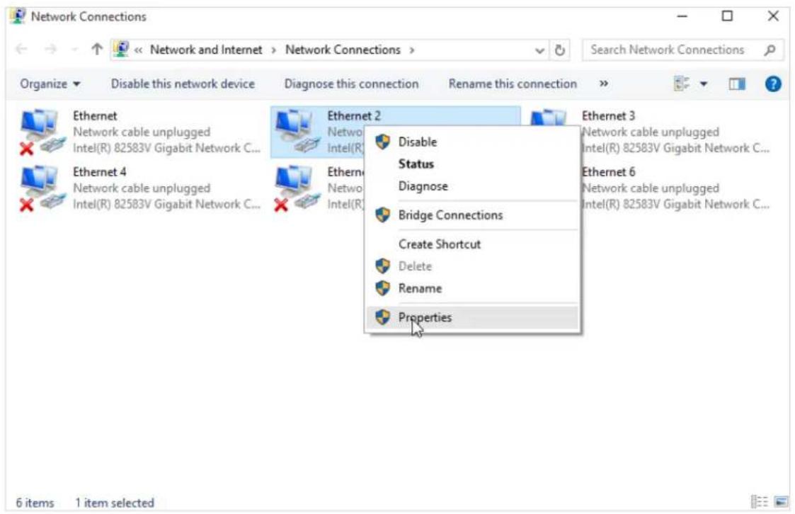
Step 4 Double-click Internet Protocol Version 4 (TCP/IPv4) or Internet Protocol Version 6 (TCP/IPv6).
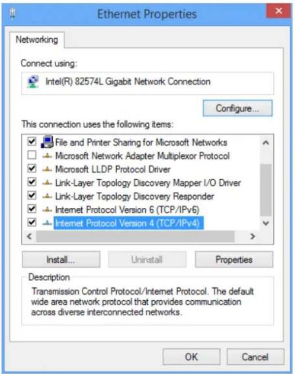
Step 5 Select Obtain an IP address automatically and Obtain DNS server address automatically, and click OK.
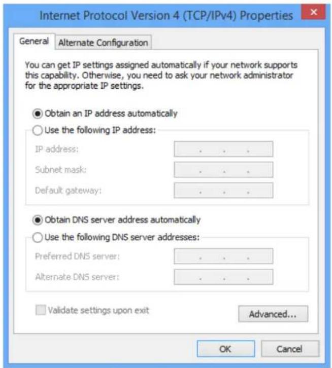
Step 6 Click OK in the Ethernet Properties window.
---End
A.1.2 Windows 8
Step 1 Right-click in the bottom right corner of the desktop and choose Open Network and Sharing Center.
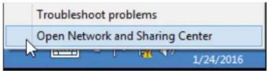
Step 2 Click Ethernet and then Properties.
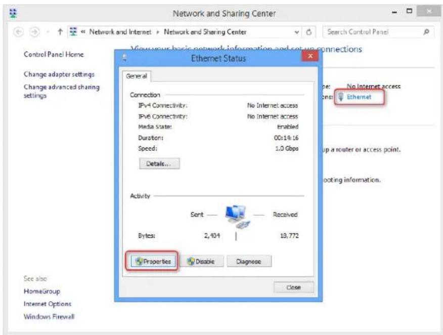
Step 3 Double-click Internet Protocol Version 4 (TCP/IPv4) or Internet Protocol Version 6 (TCP/IPv6).
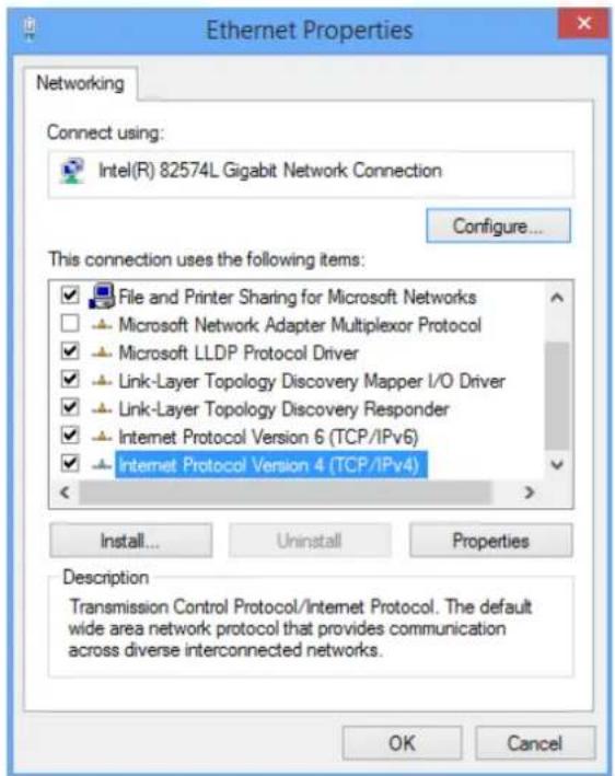
Step 4 Select Obtain an IP address automatically and Obtain DNS server address automatically, and click OK.
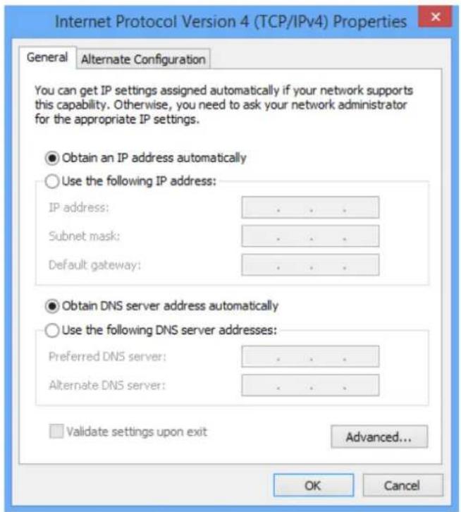
Step 5 Click OK in the Ethernet Properties window.
---End
A.1.3 Windows 7
Step 1 Click in the bottom right corner of the desktop and choose Open Network and Sharing Center.
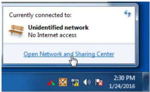
Step 2 Click Local Area Connection and then Properties.
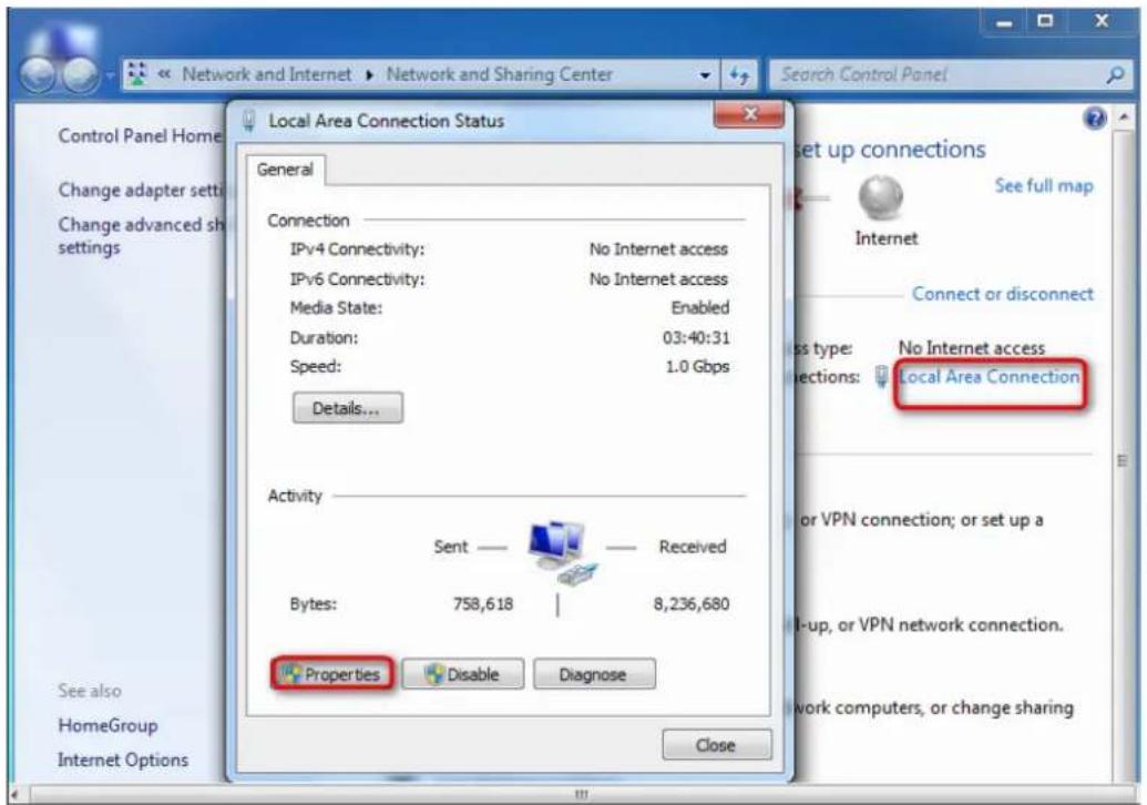
Step 3 Double-click Internet Protocol Version 4 (TCP/IPv4) or Internet Protocol Version 6 (TCP/IPv6).
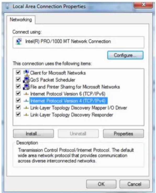
Step 4 Select Obtain an IP address automatically and Obtain DNS server address automatically, and click OK.
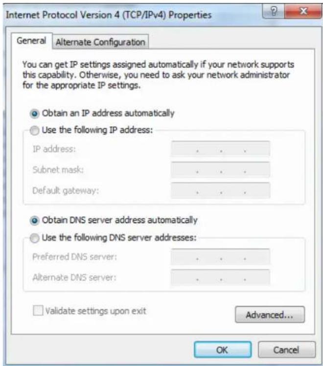
Step 5 Click OK in the Local Area Connection Properties window.
---End
A.2 Acronyms and abbreviations
| Acronym or Abbreviation | Full Spelling |
| ACL | Access control list |
| ACS | Auto-Configuration Server |
| AES | Advanced Encryption Standard |
| ALG | Application Layer Gateway |
| AP | Access Point |
| APC | Angled Physical Contact |
| ARP | Address Resolution Protocol |
| ASCII | American Standard Code for Information Interchange |
| BSSID | Basic Service Set Identifiers |
| CPE | Customer Premise Equipment |
| CPU | Central processing unit |
| CTS | Clear To Send |
| CWMP | CPE WAN Management Protocol |
| DDNS | Dynamic Domain Name System |
| DHCP | Dynamic Host Configuration Protocol |
| DHCPv6 | Dynamic Host Configuration Protocol version 6 |
| DMZ | Demilitarized zone |
| DND | Don't Disturb |
| DNS | Domain Name System |
| DTMF | Dual tone multi-frequency |
| DUID | DHCP unique identifier |
| EPON | Ethernet passive optical network |
| FQDN | Fully qualified domain name |
| FTP | File Transfer Protocol |
| FTTH | Fiber to the Home |
| HTTP | Hypertext Transfer Protocol |
| HTTPS | Hypertext Transfer Protocol Secure |
| ICMP | Internet Control Message Protocol |
| IEEE | Institute of Electrical and Electronics Engineers |
| IGMP | Internet Group Management Protocol |
| IMS | IP Multimedia Subsystem |
| IP | Internet Protocol |
| IPoE | Internet Protocol Over Ethernet |
| IPsec | Internet Protocol Security |
| IPTV | Internet Protocol television |
| IPv4 | Internet Protocol version 4 |
| IPv6 | Internet Protocol version 6 |
| ISP | Internet service provider |
| ITU | International Telecommunication Union |
| L2TP | Layer 2 Tunneling Protocol |
| LAN | Local Area Network |
| LTE | Long Term Evolution |
| MAC | Medium access control |
| MIB | Management information base |
| MLD | Multicast Listener Discovery |
| MPPE | Microsoft Point-to-Point Encryption |
| MTU | Maximum Transmission Unit |
| NAPT | Network Address Port Translation |
| NMS | Network Management System |
| OLT | Optical line termination |
| OMCI | ONU Management Control Interface |
| ONT | Optical Network Terminal |
| ONU | Optical network unit |
| OS | Operating system |
| P2P | Peer-to-peer |
| PBC | Push Button Configuration |
| PIN | Personal Identification Number |
| PON | Passive optical network |
| PPP | Point-to-Point Protocol |
| PPPoE | Point-to-Point Protocol over Ethernet |
| PPTP | Point-to-Point Tunneling Protocol |
| RA | Router Advertisement |
| RADVD | Router Advertisement Daemon |
| RDNSS | Recursive DNS Server |
| RS | Router Solicitation |
| RSSI | Received Signal Strength Indicator |
| RTP | Real-time Transport Protocol |
| RTS | Request To Send |
| RTSP | Real Time Streaming Protocol |
| SC | Subscriber connector |
| SIP | Session Initiation Protocol |
| SLAAC | Stateless address autoconfiguration |
| SNMP | Simple Network Management Protocol |
| SNTP | Simple Network Time Protocol |
| SSID | Service set identifier |
| STB | Set-top box |
| TCP | Transmission Control Protocol |
| TFTP | Trivial File Transfer Protocol |
| TKIP | Temporal Key Integrity Protocol |
| TR-069 | Technical Report - 069 |
| UDP | User Datagram Protocol |
| UI | User interface |
| ULA | Unique Local Address |
| UPnP | Universal Plug and Play |
| URI | Uniform Resource Identifier |
| URL | Uniform Resource Locator |
| VLAN | Virtual Local Area Network |
| VPN | Virtual Private Network |
| VoLTE | Voice over Long-Term Evolution |
| WAN | Wide Area Network |
| WEP | Wired Equivalent Privacy |
| WLAN | Wireless Local Area Network |
| WPA | Wi-Fi Protected Access |
| WPA-PSK | WPA-Preshared Key |
| WPS | WiFi Protected Setup |
- N300 Wi-Fi xPON ONT User Guide
- Copyright Statement
- Disclaimer
- Preface
- Conventions
- For more documents
- Technical Support
- Revision History
- Contents
- Get to know your device .... 1
- Web UI 4
- Status 8
- LAN....12
- WLAN....13
- Advanced settings....17
- Security....19
- Advance....70
- Diagnostics 81
- Admin 85
- Statistics....95
- Appendixes 96
- A.2 Acronyms and abbreviations .... 103
- Get to know your device
- Overview
- Appearance
- Indicators, ports, and buttons
- Ports & buttons
- Label
- Web UI
- Login
- Logout
- Web UI layout
- Common buttons
- Status
- Device status
- IPv6 status
- PON status
- LAN
- WLAN
- Basic settings
- Overview
- Customize the main Wi-Fi name
- Enable multiple wireless networks
- Advanced settings
- Overview
- Hide the main Wi-Fi name
- Security
- Overview
- Customize the Wi-Fi password
- Step 6 Click Apply Changes.
- Access control
- Overview
- Allow certain clients to access the Wi-Fi network
- Configuring procedure:
- WPS
- Overview
- Connect to the Wi-Fi network using the WPS button
- Choose WPS connection.
- Connect to the Wi-Fi network using PBC on the web UI
- TIP
- Connect to the Wi-Fi network by entering PIN code of clients on the ONT
- Connect to the Wi-Fi network by entering PIN code of the ONT on clients
- Status
- WAN
- Overview
- Common WAN settings
- WAN IP settings
- IPv6 WAN settings
- PPP settings
- 6rd configuration
- Port mapping
- Bridge mode
- Configure internet access on a computer
- Step 4 Click Connect to the Internet and click Next.
- Step 5 Click Broadband (PPPoE).
- Configure internet access on a router
- Router mode
- Set up a fixed IP connection
- Set up a dynamic IP connection
- Step 4 Set other common WAN parameters as required by your ISP.
- Step 5 Configure WAN IP Settings or/and IPv6 WAN Setting based on the IP protocol you choose.
- Set up a PPPoE connection
- Set up a 6rd connection
- Services
- Service
- DHCP
- Overview
- Reserve IP addresses for certain devices
- Dynamic DNS
- Enable internet users to access LAN resources using a domain name
- IGMP Proxy
- UPnP
- Firewall
- ALG
- IP/Port filtering
- MAC filtering
- Allow only specified devices to access the internet
- Port forwarding
- Enable internet users to access local services
- To access the FTP server from the internet:
- URL Blocking
- Block clients from accessing certain websites
- DMZ
- NOTE
- Enable internet users to access LAN resources
- Advance
- Advanced settings
- ARP table
- Routing
- Add a new static route rule
- Modify a static rule
- Delete an existing rule
- Show commonly used routes
- SNMP
- SNMP management framework
- SNMP operations
- IPv6 settings
- IPv6 status
- RADVD
- DHCPv6
- Diagnostics
- Overview
- Ping
- Parameter description
- Tracert
- Execute Ping to test connectivity
- Execute Traceroute to test routing
- Manual inform report
- Admin
- GPON/EPON settings
- OMCI information
- Commit/Reboot
- Backup/Restore
- Back up the configuration of the ONT
- Restore previous configuration of the ONT
- Reset the ONT
- Password
- Firmware upgrade
- ACL
- Time Zone
- TR-069
- Logout
- Logout
- Statistics
- Interface statistics
- PON statistics
- Appendixes
- A.1 Configure the computer to obtain an IPv4/IPv6 address automatically
- A.1.1 Windows 10
- Step 3 Right-click on the connection in use, and then click Properties.
- Step 4 Double-click Internet Protocol Version 4 (TCP/IPv4) or Internet Protocol Version 6 (TCP/IPv6).
- A.1.2 Windows 8
- A.1.3 Windows 7
Brand : Tenda
Model : HG3
Category : Uncategorized