
CR-3XCONTROL - Regulator KanexPro - Free user manual and instructions
Find the device manual for free CR-3XCONTROL KanexPro in PDF.


| Product Type | Power Regulator / Controller |
| Model | CR-3XCONTROL |
| Brand | KanexPro |
| Channels | 3 |
| Form Factor | 1U Rackmount |
| Dimensions (W x D x H) | 19 x 8 x 1.75 inches |
| Weight | 5.5 lbs (2.5 kg) |
| Power Input | 100-240V AC, 50/60 Hz |
| Maximum Load | 15A total |
| Output Connectors | 3 x NEMA 5-15R |
| Control Interface | Front panel buttons, RS-232, IP |
| Sequencing Delay | Adjustable 1-10 seconds per outlet |
| Surge Protection | Yes, 1080 Joules |
| EMI/RFI Filtering | Yes |
| Input Voltage Monitor | Digital display |
| Remote Control | Via RS-232 or Ethernet (TCP/IP) |
| Safety Certifications | CE, FCC, RoHS |
| Operating Temperature | 32°F to 104°F (0°C to 40°C) |
| Storage Temperature | -4°F to 158°F (-20°C to 70°C) |
| Included Accessories | Power cord, rack ears, manual |
Frequently Asked Questions - CR-3XCONTROL KanexPro
User questions about CR-3XCONTROL KanexPro
0 question about this device. Answer the ones you know or ask your own.
Ask a new question about this device
Download the instructions for your Regulator in PDF format for free! Find your manual CR-3XCONTROL - KanexPro and take your electronic device back in hand. On this page are published all the documents necessary for the use of your device. CR-3XCONTROL by KanexPro.
USER MANUAL CR-3XCONTROL KanexPro
natural_image
Exterior view of a black electronic device with red ports and green connectors, no visible text or symbols on the main body.Integrated IR/RS-232 and Relay Controller
USER MANUAL
DISCLAIMERS
The information in this manual has been carefully checked and is believed to be accurate. KanexPro assumes no responsibility for any infringements of patents or other rights of third parties which may result from its use.
KanexPro assumes no responsibility for any inaccuracies that may be contained in this document. KanexPro also makes no commitment to update or to keep current the information contained in this document.
KanexPro reserves the right to make improvements to this document and/or product at any time and without notice.
COPYRIGHT NOTICE
No part of this document may be reproduced, transmitted, transcribed, stored in a retrieval system, or any of its part translated into any language or computer file, in any form or by any means—electronic, mechanical, magnetic, optical, chemical, manual, or otherwise—without express written permission and consent from KanexPro.
© Copyright 2017 by KanexPro. All Rights
Reserved.
KanexPro TRADEMARK ACKNOWLEDGMENTS
All products or service names mentioned in this document may be trademarks of the companies with which they are associated.
SAFETY PRECAUTIONS
Please read all instructions before attempting to unpack, install or operate this equipment and before connecting the power supply.
Please keep the following in mind as you unpack and install this equipment:
• Always follow basic safety precautions to reduce the risk of fire, electrical shock and injury to persons.
- To prevent fire or shock hazard, do not expose the unit to rain, moisture or install this product near water.
• Never spill liquid of any kind on or into this product.
- Never push an object of any kind into this product through any openings or empty slots in the unit, as you may damage parts inside the unit.
• Do not attach the power supply cabling to building surfaces.
- Use only the supplied power supply unit (PSU). Do not use the PSU if it is damaged.
- Do not allow anything to rest on the power cabling or allow any weight to be placed upon it or any person walk on it.
- To protect the unit from overheating, do not block any vents or openings in the unit housing that provide ventilation and allow for sufficient space for air to circulate around the unit.
REVISION HISTORY
| VERSION NO. | DATE (DD/MM/YY) | SUMMARY OF CHANGE |
| RDV1 | 07/01/16 | Preliminary release |
| RDV2 | 21/04/16 | Add WebGUI |
| RDV3 | 14/06/16 | Revised trigger event number to 8 |
| VS0 | 21/02/17 | Updated text/diagrams |
CONTENTS
- INTRODUCTION....1
- APPLICATIONS .... 1
- PACKAGE CONTENTS......2
- SYSTEM REQUIREMENTS....3
- FEATURES....3
- OPERATION CONTROLS AND FUNCTIONS....4
6.1 Front Panel....4
6.2 Rear Panel 5
6.3 IR Cable Pin Assignment....6
6.5 Telnet Control 9
6.6 WebGUI Control....11
6.6.1 Macro Settings 12
6.6.2 Extension Macro 13
6.6.3 Command Settings....13
6.6.4 Network Settings....14
6.6.5 System Settings....15
- CONNECTION DIAGRAM....16
- SPECIFICATIONS....17
- ACRONYMS 18
- Warranty 19
1. INTRODUCTION
The KanexPro CR-3XCONTROL is a central control system designed to control wide variety of devices such as projectors to dvd players and other audio-video IR, RS-232 and relay based sources. It comes with eight external trigger connections which directly activates 8 (of 16 total) user defined macro events stored within the unit. All 16 macros are accessible Tobe activated via the WebGUI, or by Telnet. Those user defined macros can send commands to remote devices via Ethernet, IR (×4), relay trigger (×4), or RS-232/422/485 (×1) allowing for the control of a large array of devices by the push of button.
An integrated IR code learning function is also available, allowing the user to store and re-transmit the IR codes sent by nearly any standard IR remote. Comprehensive user control interfaces are available including WebGUI, Telnet and console (RS-232 in). The controller also supports Power over Ethernet (PoE) allowing it to be powered directly from a standard PoE network switch, without the need for an external power adapter, allowing for incredible installation and flexibility.
Applications:
Ideal for use with-in smart home control systems, classrooms, conference rooms or showrooms where audio-visual devices can be controlled by just a click of a button.
2. PACKAGE CONTENTS
• 1 × Control System Center
• 1 × IR Learner/Extender Cable
- 4 × IR Blaster Cable
- 7 × Terminal Block Connectors
• 1 × 5V/2.6A Power Adaptor
• 1 × Operation Manual
3. SYSTEM REQUIREMENTS
- Relay trigger controllable equipment such as projection screens, blinds, power switches, etc. or equipment which can be controlled by IR remote.
- An active internet connection from a switch or router for control of Ethernet devices.
4. KEY FEATURES
- 8 trigger inputs linked directly to 8 user macros allowing instant control activation
- 4 relay trigger outputs to control devices such as projector screens, lighting, etc.
• 4 IR outputs to control devices such as TVs, media players, etc.
• Integrated IR code learning functionality
• Multiple user control interfaces including WebGUI, Telnet and RS-232 - Simple configuration of macros, triggers and relay settings via the WebGUI
• PoE (Power over Ethernet) support - Firmware can easily be updated in the field via USB
5. OPERATION CONTROLS AND FUNCTIONS
5.1 Front Panel
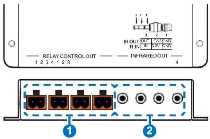
1 RELAY CONTROL OUT 1\~4: Connect to devices that support relay triggered power (0\~30VDC/10A or 0\~250VAC/10A) activation to control them via macro commands.
2 INFRARED OUT 1\~4: Connect to the provided IR Blaster to transmit IR signals to devices within direct line-of-sight of the IR Blaster.
5.2 Rear Panel
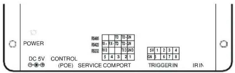
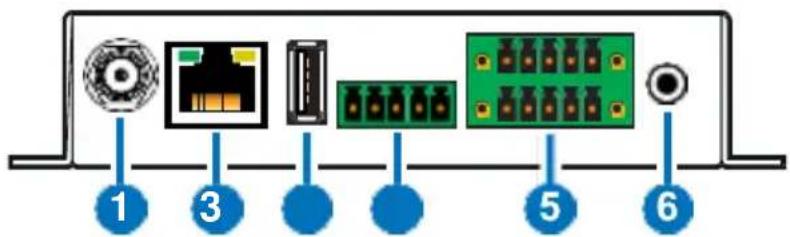
1 DC 5V: Plug the 5V DC power adapter into the unit and connect it to an AC wall outlet for power.
Note: If the unit is being powered by PoE then this connection is optional.
2 CONTROL (PoE): Connect directly, or through a network switch, to your PC/laptop to control the unit via Telnet/WebGUI.
Note: If the unit is connected to a network switch that provides PoE then no power adapter is required to power the unit.
3 SERVICE: This slot is reserved for firmware update use only.
4 COM PORT: Connect to the device you wish to control via a 3(or 5)-pin adapter cable to send RS-232/422/485 commands from the unit. Baud rates up to 115200 are supported. For pin connection details please refer to the graphic above.
5 TRIGGER IN: Connect to any device with trigger or switch functionality such as window security alarms, motion detectors, door switches, etc. Each of the 8 trigger inputs will activate the associated macro when triggered. A minimum of 5V DC is required to activate the trigger. For pin connection details please refer to the graphic above.
6 IR IN: Connect to the provided IR Extender to allow IR control of the unit or for learning IR commands. Ensure that the remote being used is within direct line-of-sight of the IR Extender. For additional IR learning details please refer to section 6.6.3.
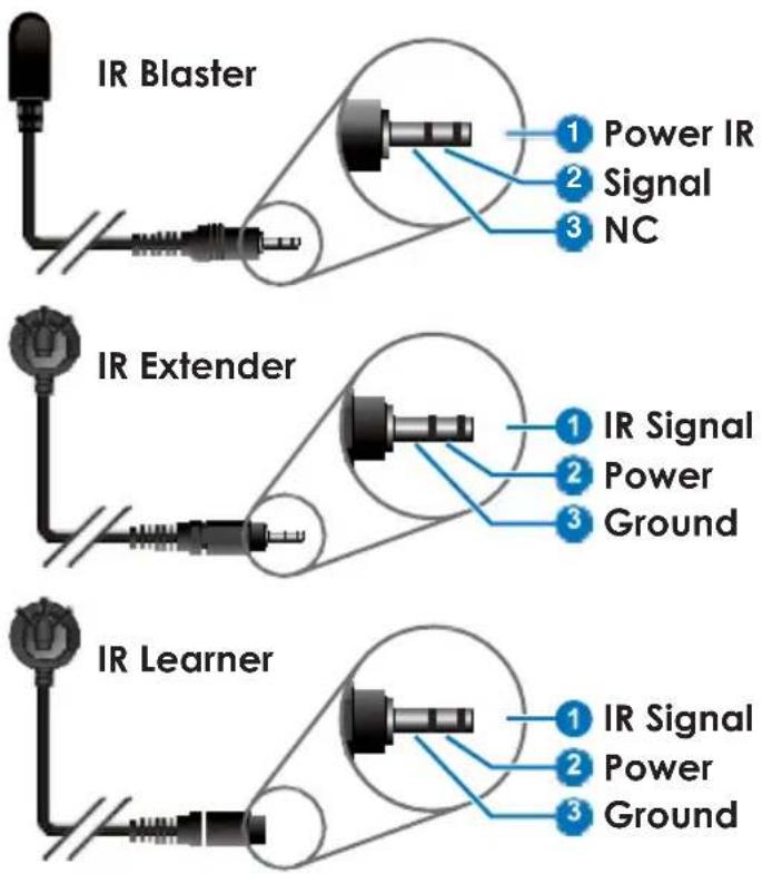
5.3 IR Cable Pin Assignment
| COMMAND | DESCRIPTION |
| IPCONFIG | Display the current IP configuration. |
| SIPADDR X.X.X.X | Set Ethernet IP address. X=0 255 |
| SNETMASK X.X.X.X | Set Ethernet netmask. X=0 255 |
| SGATEWAY X.X.X.X | Set Ethernet gateway. X=0 255 |
| SIPMODE N | Set Ethernet mode. N=STATIC, DHCP |
| VER | Display the firmware version. |
| FADEFAULT | Reset the unit to factory defaults. |
| ETH_FADEFAULT | Reset the Ethernet settings to the factory defaults. |
| REBOOT | System reboot. |
| HELP (?) | Show command list. |
| HELP N | Show a description of commands. N= Name\ |
| RELAY N N1 | Relay control. N=1 4 [Port Number] N1=OPEN, CLOSE, TOGGLE |
| IREMIT N N1 | Send IR control code. N=IR1 IR4 [Port Number] N1= Data\ Ex: IREMIT IR1 9333,0-157,AF,14,40,14,18,14,43,14,1B,14,0- |
| IRLEARN N | Initiate IR learning.N=0 [Native IR Format]Note: Will display the IR data when an IR signal (30~50KHz) is received. |
| COMCONF N N1 N2 N3 N4 | COM port configuration.N=RS232, RS422, RS485N1=4800, 9600, 19200, 38400, 57600, 115200, 250000, 1000000 [Bitrate]N2=7~8 [Data Bits]N3=NONE, ODD, EVEN [Parity]N4=1 [Stop Bits] |
| COMSEND N | COM data send.N={Data to send (1~512 characters)} |
| TELNET_TIMEOUT N | Turn the Telnet timeout on or off.N=ON, OFF |
| MACRO N N1 | Start or stop a macro.N=RUN, STOPN1=1~16 [Macro ID], NONEEx: MACRO RUN 1MACRO STOP |
Note: Commands will not be executed unless followed by a carriage return. Commands are not case-sensitive.
6.5 Telnet Control
Before attempting to use Telnet control, please ensure that both the unit and the PC/Laptop are connected to the same active networks.
To access Telnet in Windows 7, click on the "Start" menu and type "cmd" in the search field, then press "Enter". Under Windows XP go to the "Start" menu, click on "Run", type "cmd" then press "Enter". Under Mac OS X, go to "Go→Applications→Utilities→Terminal". See below for reference.
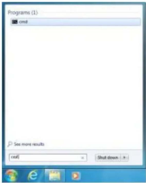
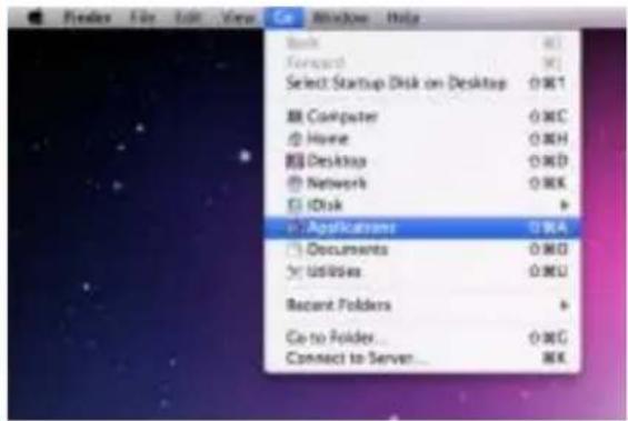
Once in the CLI (Command Line Interface) type "Telnet" followed by the IP address of the unit and "23", then hit "Enter".
Microsoft Windows [Version 6.1.7601]
Copyright (c) 2009 Microsoft Corporation. All rights reserved.
C:\Users\Administrator>telnet 192.168.5.80 23
This will connect us to the unit we wish to control. Type "help" to list the available commands.
HELP : SHOW DESCRIPT OF COMMAND
    USE <HELP N, N=COMMAND NAME> TO SHOW DESCRIPT OF COMMAND
? : SHOW DESCRIPT OF COMMAND
    USE <? N, N=COMMAND NAME> TO SHOW DESCRIPT OF COMMAND
IPCONFIG : DISPLAY THE CURRENT IPCONFIG
SIPADDR : SET ETHERNET IP ADDRESS
SMETMASK : SET ETHERNET NETMASK
SGATEWAY : SET ETHERNET GATEWAY
SIPMODE : SET ETHERNET IP MODE
UER : SHOW UNIT FIRMWARE VERSION
PADEFAULT : ALL CONFIGURE SET TO FACTORY DEFAULT
ETH_PADEFAULT : ALL ETHERNET CONFIGURE SET TO FACTORY DEFAULT
REBOOT : SYSTEM REBOOT
IREMIT : SEND IR CONTENET
IRLEARN : LEARNING IR CODE
TRIGGER : TRIGGER SETTING
RELAY : RELAY CONTROL
COMCONF : DRIVER COMPORT CONFIG
COMSEND : SEND DATA VIA COMPORT
TELNET_TIMEOUT : SET TELNET TIME OUT ON/OFF
MACRO : MACRO CONTROL
Note:
- Commands will not be executed unless followed by a carriage return. Commands are not case-sensitive.
- If the IP address is changed then the IP address required for Telnet access will also change accordingly.
6.6 WebGUI Control
• Install the Device Discovery Tool
Please obtain the Device Discovery software from your authorized dealer and save it in a directory where you can easily find it. Connect the unit and your PC/Laptop to the same active network and execute the Device Discovery software. Click on “Find Devices on Network” and a list of devices connected to the local network will show up indicating their current IP address.
Note: The unit's default IP address is 192.168.1.50

By clicking on one of the listed devices you will be presented with the network details of that particular device. If you choose, you can alter the static IP network settings for the device, or switch the unit into DHCP mode to automatically obtain proper network settings from a local DHCP server. To switch to DHCP mode, please select DHCP from the IP mode drop-down, then click "Save" followed by "Reboot".
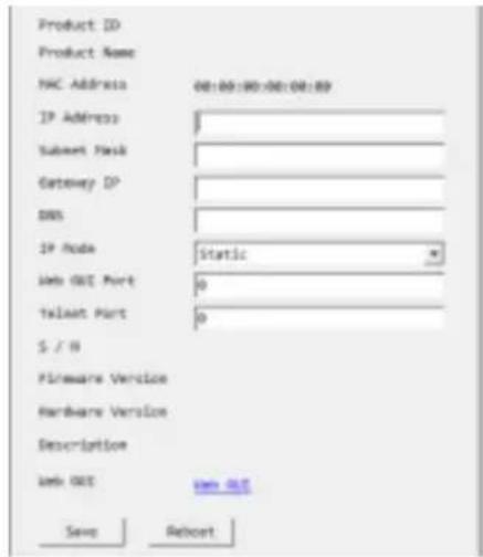
Once you are satisfied with the network settings, you may use them to connect via Telnet or WebGUI. The network information window provides a convenient link to launch the WebGUI directly.
- Login to the WebGUI
Open a web browser on a PC/Laptop that is connected to an active network and type the unit's IP address into the web address entry bar. The login screen will appear and ask for a Username and Password. The default username and password is "admin". Please enter the information and then click "Submit" to log in.
Note: The unit's default IP address is 192.168.1.50
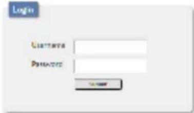
On the left side of the browser you will see the following menu tabs: Macro Settings, Extension Macro, Command Settings, Network Settings, and System Settings to allow for user to configure the unit to your needs.
6.6.1 Macro Settings
Click on the "Macro Settings" tab to execute/edit the settings for the primary macro buttons. These macros can be executed by activating the 8 input triggers on the unit as well as via the WebGUI or Telnet.
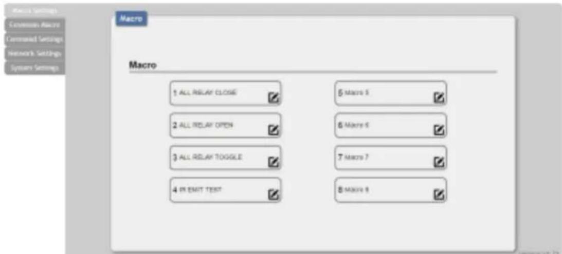
Macros 1\~8 align with Trigger In 1\~8. When a trigger is activated the unit will execute the associated macro command.
There are multiple macros defined by default for testing the unit's functionality. Click on these macros to demonstrate and test various functions:
CR-3XCONTROL
(1) Macro 1: Sequentially close Relays 1 through 4 with a 100ms delay
(2) Macro 2: Sequentially open Relays 1 through 4 with a 100ms delay
(3) Macro 3: Sequentially toggle the state of Relays 1 through 4 with a 100ms delay
(4) Macro 4: Sequentially send IR signals from emitters 1 through 4 with a 100ms delay.
(5) Macro 5+: Send a sample text string over the COM port with a 100ms delay afterwards.
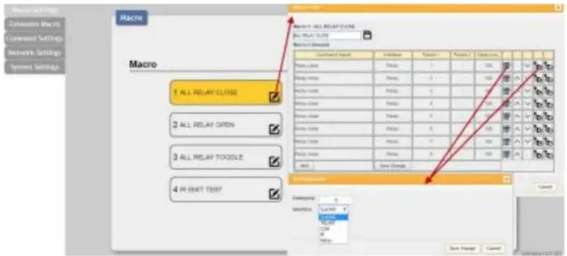
Click on the ☐on to edit each button's macro. At the top of the Macro Edit window is a text field where you can edit the name of the macro. Type your new macro name into the box and then click the ☐ icon to save it.
Within the Macro Edit window the up/down arrows will change the command execution order. The icon allows you to edit the delay and interface for the command. The icon will delete the command.
Click on the icon to insert a new command before the current one. Select one of the pre-defined commands from the list. (Details on how to create these pre-defined commands are later in this section.) After selecting a command, you will need to choose the delay and interface for the command.
(1) Delay(ms): This setting is the length of time to wait before sending the next command and is set in milliseconds.
(2) Interface: The interface for sending commands can be set to the unit itself (SysCMD), to a specified IP address (TELNET), to a specified RS-232 port (COM), to a specified IR port (IR) or to trigger
a relay port (Relay). Sending commands to devices on the local network, or across the internet requires the IP address and network port number of the destination device.
Once the destination information is complete please click on the "Save Change" button.
Note: It is strongly suggested to not set a delay time less than 100ms for system, RS-232, IR, and relay commands or less than 500ms for Telnet commands to ensure that the command is properly received and executed before the next command is sent.
When you have finished editing the macro click on "Save Change".
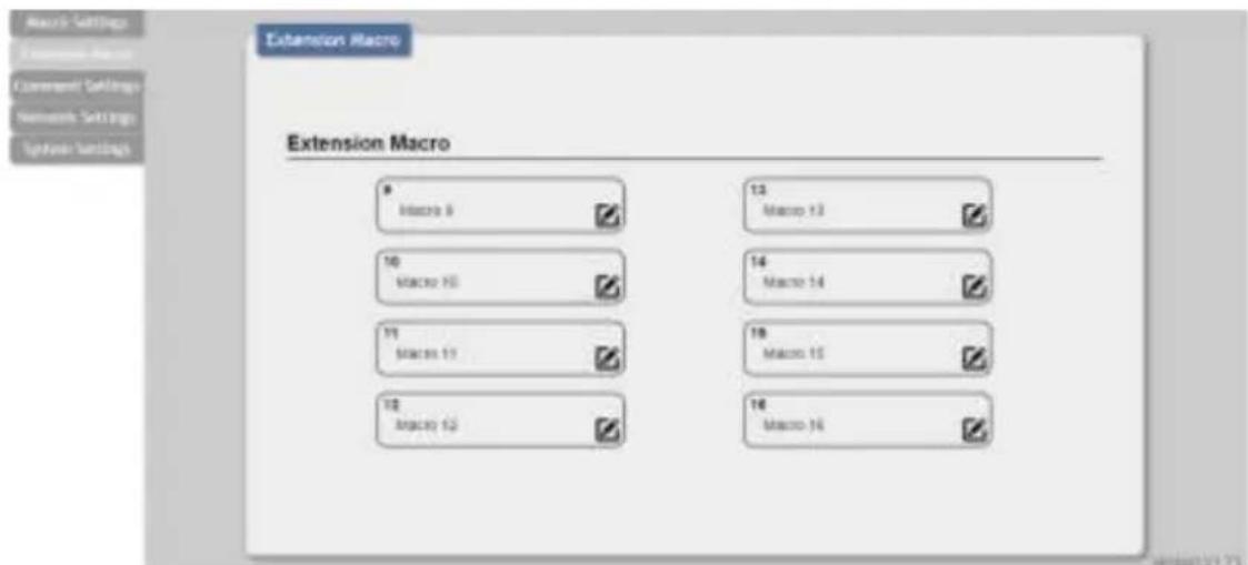
6.6.2 Extension Macro
Click on the “Extension Macro” tab to execute/edit the additional software-only macro buttons. These macros can only be executed via the WebGUI or Telnet. Macro editing in this tab is identical to editing the prior tab's macros.
6.6.3 Command Settings
Click on the “Command Settings” tab to create, edit or delete commands. The number of commands that can be stored in the unit is limited by memory. It is generally recommended that commands be under 128 characters long (including spaces). However, if longer commands are needed there is limited support for commands up to 512 characters long. In this case the number of (up to) 512 character commands is limited to 32 and the remaining 96 commands must be under 128 characters. Click on “Save Change” to save the command.
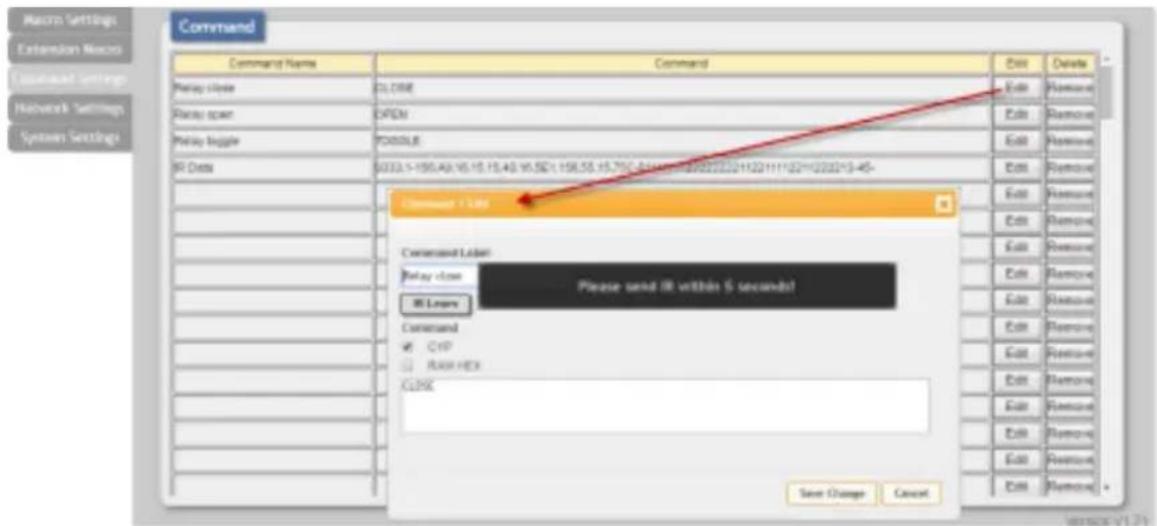
(1) Renaming Command: You may rename the command, if you wish, by changing the text in the "Command Label" field.
(2) Learning IR Command: To learn an IR command, first make sure the included IR Receiver is connected to the unit's IR IN port, then press "IR Learn" within the command edit window. After doing this a notice will appear in the WebGUI to send the IR signal within 5 seconds. When you see this, point your remote control at the IR receiver and press the button that contains the command you wish to learn. A command string will then appear in the text entry window containing the information captured from the IR remote. Click on "Save Change" to save the command.
(3) Entering Text Command: For plain text commands, simply enter the text command into the entry window. Click on "Save Change" to save the command.
Note: Some commands may require a carriage return (e.g. \r or \x0D) at the end to be accepted by the destination device.
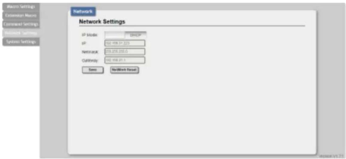
6.6.4 Network Settings
Click on the "Network Settings" tab to change the network settings for the unit. You can manually set the IP address, netmask and gateway address in "Static IP" mode, or you can obtain an IP address automatically by enabling DHCP.
6.6.5 System Settings
Click on the “System Settings” tab to make changes to various system settings. From this tab, you can change the WebGUI login password and login timeout settings. You may also save the full system configuration, including all macros, to your connected PC/Laptop or restore them from a previously saved configuration. Finally, this tab provides buttons to reset the unit to factory defaults and to reboot the unit.
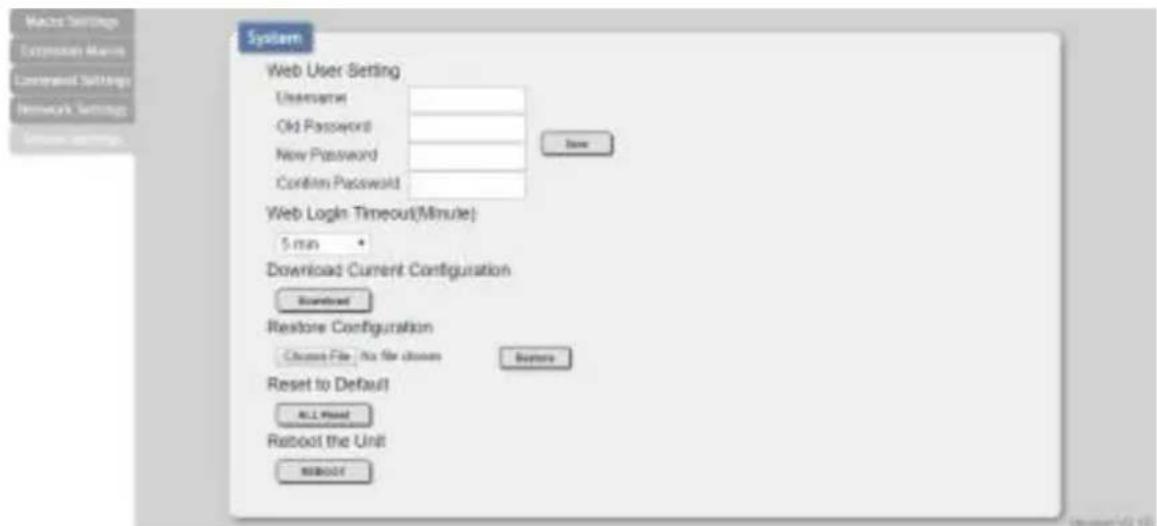
Note: Please ensure that all commands and settings have been backed up before performing an "All Reset" as the procedure will return all settings back to the factory default.
6. CONNECTION DIAGRAM
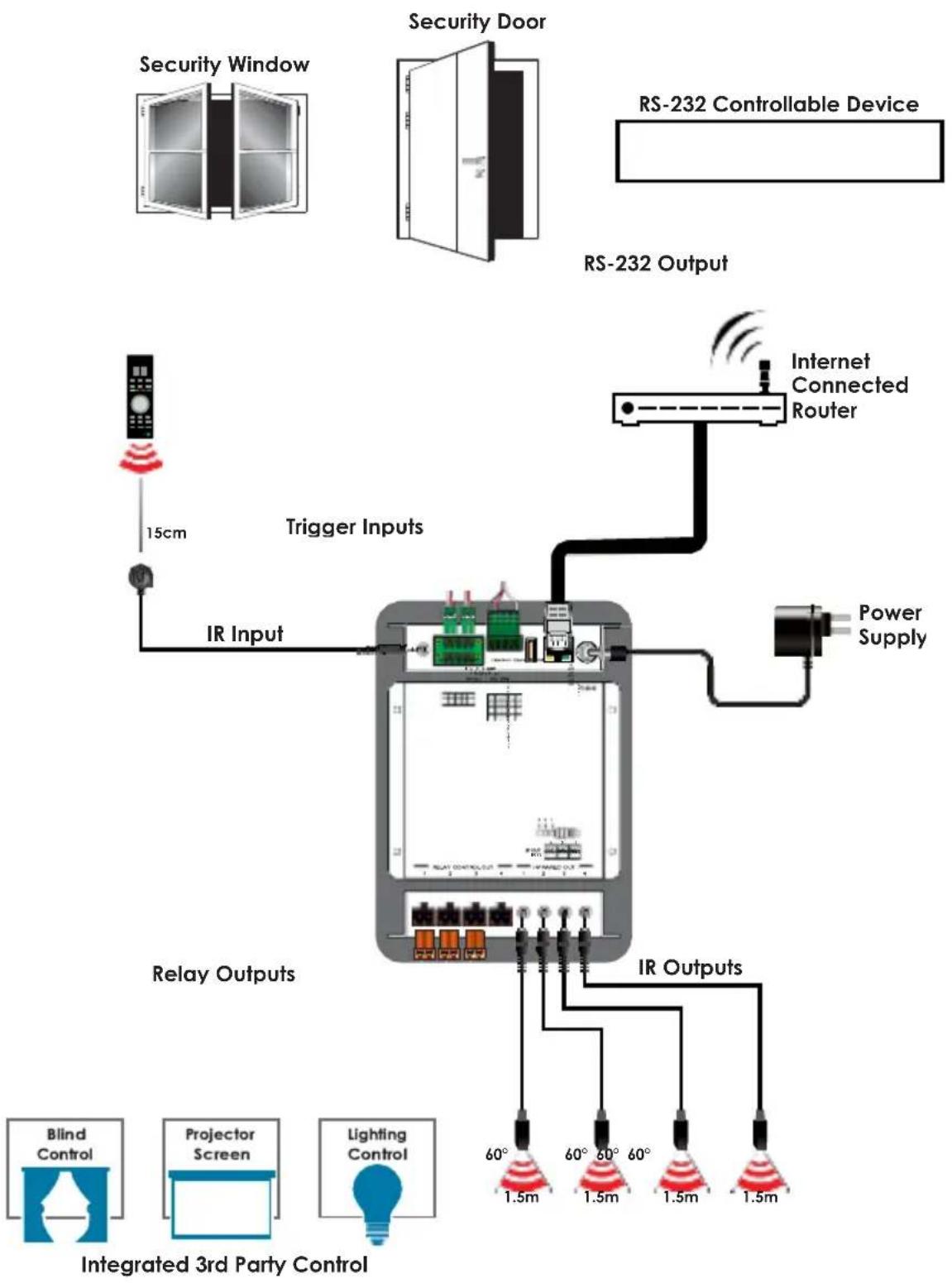
flowchart
graph TD
    A["Security Window"] --> B["Security Door"]
    B --> C["RS-232 Output"]
    C --> D["Internet Connected Router"]
    D --> E["Power Supply"]
    F["IR Input"] --> G["Trigger Inputs"]
    G --> H["Relay Outputs"]
    H --> I["IR Outputs"]
    I --> J["Blind Control"]
    I --> K["Projector Screen"]
    I --> L["Lighting Control"]
    style A fill:#f9f,stroke:#333
    style B fill:#ccf,stroke:#333
    style C fill:#cfc,stroke:#333
    style D fill:#fcc,stroke:#333
    style E fill:#cff,stroke:#333
    style F fill:#ffc,stroke:#333
    style G fill:#cfc,stroke:#333
    style H fill:#fcc,stroke:#333
    style I fill:#ffc,stroke:#333
    style J fill:#cfc,stroke:#333
    style K fill:#ffc,stroke:#333
    style L fill:#cfc,stroke:#333
- SPECIFICATIONS
| Input Ports | 1×IR Learner/Extender (3.5mm), 8×Trigger (10-pin Terminal Block) |
| Output Ports | 4×IR Blaster (3.5mm), 4×Relay (2-pin Terminal Block), 1×COM (5-pin Terminal Block) |
| Control Interfaces | 1×IP Control (RJ45) |
| IR Frequency | 30 - 50kHz (30 - 60kHz under ideal conditions) |
| Baud Rate | Up to 115200bps |
| Power Supply | 5V/2.6A DC (US/EU standards, CE/FCC/UL certified) |
| ESD Protection | Human Body Model: ±12kV (Air Discharge) ±8kV (Contact Discharge) |
| Dimensions | 128mm×25mm×108mm (W×H×D) [Case Only] 128mm×25mm×118mm (W×H×D) [All Inclusive] |
| Weight | 400g |
| Chassis Material | Metal |
| Silkscreen Color | Black |
| Operating Temperature | 0°C - 40°C/32°F - 104°F |
| Storage Temperature | -20°C - 60°C/-4°F - 140°F |
| Relative Humidity | 20 - 90% RH (Non-condensing) |
| Power Consumption | 3.63W |
- ACRONYMS
| ACRONYM | COMPLETE TERM |
| CLI | Command Line Interface |
| GUI | Graphical User Interface |
| IR | Infrared |
| PC | Personal Computer |
| PoE | Power over Ethernet |
| USB | Universal Serial Bus |
10. Warranty
A. LIMITED WARRANTY
KanexPro ^TM warrants that (a) its products (the “Product”) will perform greatly in agreement with the accompanying written materials for a period of 36 months (3 full year) from the date of receipt and (b) that the product will be free from defects in materials and workmanship under normal use and service for a period of 3 years.
B. CUSTOMER REMEDIES
KanexPro entire liability and Customer's exclusive remedy shall be, at KanexPro option, either return of the price paid for the product, or repair or replacement of the Product that does not meet this Limited Warranty and which is returned to KanexPro with a copy of customers' receipt. This Limited Warranty is void if failure of the Product has resulted from accident, abuse, or misapplication. Any replacement Product will be warranted for the remainder of the original warranty period of 1 year, whichever is longer.
C. NO OTHER WARRANTIES
To the maximum extent permitted by applicable law, KanexPro disclaims all other warranties, either express or implied, including, but not limited to implied warranties of merchantability and fitness for a particular purpose, with regard to the product and any related written materials. This limited warranty gives customers specific legal rights. Customers may have other rights depending on the jurisdiction.
D. NO LIABILITY FOR DAMAGES
To the maximum extent permitted by applicable law, in no event shall KanexPro be liable for any damages whatsoever (including without limitation, special, incidental, consequential, or indirect damages for personal injury, loss of business profits, business interruption, loss of business information, or any other pecuniary loss) arising out of the use of or inability to use this product, even if KanexPro has been advised of the possibility of such damages.
KanexPro™
Brea, California
KanexPro.com
- Integrated IR/RS-232 and Relay Controller
- DISCLAIMERS
- COPYRIGHT NOTICE
- KanexPro TRADEMARK ACKNOWLEDGMENTS
- SAFETY PRECAUTIONS
- CONTENTS
- INTRODUCTION
- Applications:
- PACKAGE CONTENTS
- SYSTEM REQUIREMENTS
- KEY FEATURES
- OPERATION CONTROLS AND FUNCTIONS
- Front Panel
- Rear Panel
- IR Cable Pin Assignment
- Telnet Control
- Note:
- WebGUI Control
- • Install the Device Discovery Tool
- - Login to the WebGUI
- Macro Settings
- CR-3XCONTROL
- Extension Macro
- Command Settings
- Network Settings
- System Settings
- CONNECTION DIAGRAM
- Warranty
- LIMITED WARRANTY
- CUSTOMER REMEDIES
- NO OTHER WARRANTIES
- NO LIABILITY FOR DAMAGES
- KanexPro™
Brand : KanexPro
Model : CR-3XCONTROL
Category : Regulator