
GREY Plus - Motion detector Satel - Free user manual and instructions
Find the device manual for free GREY Plus Satel in PDF.


| Product Type | Digital dual technology motion detector (PIR + MW) |
| Dimensions | 63 x 96 x 49 mm |
| Weight | 100 g |
| Supply Voltage | 12 VDC ±15% |
| Standby Current Consumption | 15 mA |
| Maximum Current Consumption | 18 mA |
| Alarm Output | NC relay, 40 mA / 16 VDC |
| Anti-Mask Output | NC relay, 40 mA / 24 VDC [GREY Plus] |
| Tamper Output | NC, 100 mA / 30 VDC |
| Microwave Frequency | 24 GHz |
| Detectable Speed | 0.3 to 3 m/s |
| Alarm Signaling Period | 2 s |
| Warm-up Period | 35 s |
| Recommended Installation Height | 2.4 m |
| Coverage Area (PET disabled) | 15 m x 11 m, 89° |
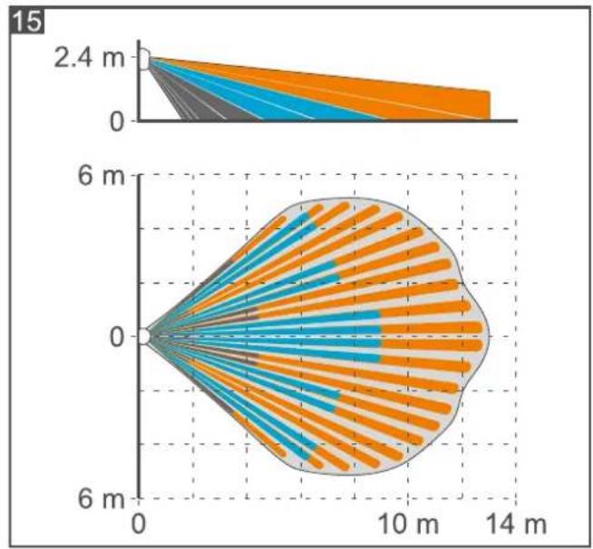
| Coverage Area (PET enabled) | 13 m x 11 m, 81° |
| Security Grade | Grade 2 (EN 50131-2-4) |
| Standards Complied | EN 50131-1, EN 50131-2-4, EN 50130-4, EN 50130-5 |
| Environmental Class | II (EN 50130-5) |
| Operating Temperature Range | -10°C to +55°C |
| Maximum Humidity | 93±3% |
| Pet Immunity | Up to 15 kg |
| Anti-Mask Feature | Microwave-based (GREY Plus) |
| LED Indicator | Bi-color (red/green), remote enable/disable |
| Alarm Memory | Available via MEM terminal |
| Sensitivity Adjustment | Separate for PIR and MW sensors |
Frequently Asked Questions - GREY Plus Satel
User questions about GREY Plus Satel
0 question about this device. Answer the ones you know or ask your own.
Ask a new question about this device
Download the instructions for your Motion detector in PDF format for free! Find your manual GREY Plus - Satel and take your electronic device back in hand. On this page are published all the documents necessary for the use of your device. GREY Plus by Satel.
USER MANUAL GREY Plus Satel
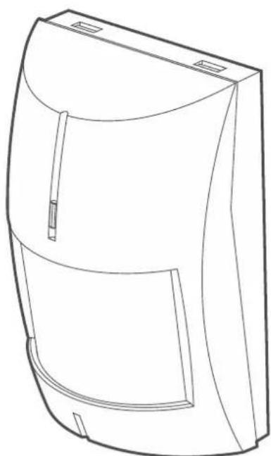
Digital dual technology motion detector
CE
Firmware version 1.3 grey_en 08/21
The device should be installed by qualified personnel.
Prior to installation, please read carefully this manual.
Changes, modifications or repairs not authorized by the manufacturer shall void your rights under the warranty.
SATEL aims to continually improve the quality of its products, which may result in changes in their technical specifications and software. Current information about the changes being introduced is available on our website.
Please visit us at: https://support.satel.eu
The declaration of conformity may be consulted at www.satel.eu/ce
The following symbols may be used in this manual:

CONTENTS
- Features ......2
- Description....2
Anti-mask feature [GREY Plus] 2
Supervision features....2
LED indicator....2
Alarm memory ....3
- Electronics board....3
- Selecting a mounting location....4
- Installation 5
- Start-up and walk test....8
Separate testing of sensors....9
Configuring the anti-masking settings....9
- Specifications 10
The GREY / GREY Plus detector detects motion in the protected area. This manual applies to the detector with electronics version H.
1. Features
- Motion detection with two sensors: passive infrared sensor (PIR) and microwave sensor (MW).
- Adjustable detection sensitivity of both sensors.
- Capability of separate sensor testing.
• Digital motion detection algorithm.
• Digital temperature compensation. - Pet immunity up to 15 kg.
- Microwave based anti-mask feature [GREY Plus].
• Built-in end-of-line resistors (2EOL: 2 x 1.1 kΩ). - Bi-color LED indicator.
- Remote LED enable / disable.
- Alarm memory.
- Supervision of motion detection system and supply voltage.
- Tamper protection against enclosure opening.
2. Description
The alarm output will turn on for 2 seconds when the infrared sensor (PIR) and the microwave sensor (MW) detect motion within a time period shorter than 5 seconds.
Anti-mask feature [GREY Plus]
Detection by the microwave sensor of an object moving at a distance of 10-20 centimeters from the detector is interpreted as an attempt to mask the detector and causes the anti-mask output to turn on for 5 seconds. Objects permeable to microwaves, but isolating the infrared radiation are not detected by the anti-mask feature.
i The anti-mask feature does not meet the EN 50131-2-4 requirements.
Supervision features
In the event of the voltage drop below 9 V ( ± 5%) for more than 2 seconds or the motion detection system failure, the detector will signal a trouble. The trouble is indicated by the alarm output turning on and the LED lighting up red. Signaling will continue as long as the trouble exists.
LED indicator
The LED indicates:
- warm-up – flashing red and green for about 35 seconds;
- motion detected by microwave sensor – ON in green for 2 seconds;
- motion detected by PIR sensor – ON in green for 2 seconds;
- alarm – ON in red for 2 seconds;
- alarm memory – flashing red;
- trouble – ON in red for entire duration of the trouble.
Enabling the LED by using a jumper
If you put a jumper across the LED pins in ON position, the LED will be enabled, i.e. it will indicate the events described above (the LED cannot be enabled / disabled remotely). If you put a jumper across the LED pins in OFF position, the LED will be disabled, i.e. it will only indicate warm-up and trouble (but the LED can be enabled / disabled remotely).
Remote LED enable / disable
The LED terminal is provided to allow remote LED enable / disable. When the terminal is connected to common ground, the LED is enabled. When the terminal is disconnected from common ground, the LED is disabled.
If the detector is used in the INTEGRA / INTEGRA Plus alarm system, you can connect to the terminal the OC type control panel output programmed e.g. as “Zone test status” or “BI switch”.
Alarm memory
If the LED is enabled, the detector can signal the alarm memory. The MEM terminal is provided to allow the alarm memory enable / disable. The alarm memory is enabled, when the terminal is connected to common ground. The alarm memory is disabled, when the terminal is disconnected from common ground. If the alarm memory is enabled and an alarm occurs, the LED will start flashing red. Indication of the alarm memory will continue until the alarm memory is enabled again (the MEM terminal is connected to common ground). Disabling the alarm memory will not stop the alarm memory indication.
If the detector is used in the INTEGRA / INTEGRA Plus alarm system, you can connect to the MEM terminal the OC type control panel output programmed e.g. as "Armed status".
3. Electronics board

Do not touch the pyroelectric sensor, so as not to soil it.




① terminals:
AM - anti-mask output (NC relay) [GREY Plus].
NC - alarm output (NC relay).
TMP - tamper output (NC).
COM - common ground.
12V - power input.
LED - LED indicator enable / disable.
MEM - alarm memory enable / disable.
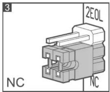
② pins for configuration of the detector outputs. Available settings are shown in the figures:
2 - built-in resistors are used - connect the detector outputs as shown in Fig. 12 or 13.
3 - built-in resistors are not used - connect the detector outputs as shown in Fig. 11.
③ tamper switch.
④ microwave sensor.
⑤ fixing screw hole.
⑥ bi-color LED indicator.
⑦ PIR sensor (dual element pyrosensor).
⑧ pins for configuration of the detector:
PET – enable / disable the pet immunity option:
jumper in ON position – option enabled (Fig. 4).
jumper in OFF position – option disabled (Fig. 5).
LED - enable / disable the LED:
jumper in ON position – LED enabled (Fig. 4).
jumper in OFF position – LED disabled (Fig. 5).
⑨ potentiometer for adjustment of PIR sensor sensitivity.
⑩ potentiometer for adjustment of microwave sensor sensitivity.
When setting the sensitivity of the MW sensor, keep in mind that microwaves can penetrate e.g. glass, plaster walls, non-metal doors, etc.
4. Selecting a mounting location


![graph TD A["Start"] --> B{Decision} B -->|Yes| C["Process Step 1"] B -->|No| D["Process Step 2"] C --> E["End"] D --> E E --> F["Checkmark"] style A fill:#f9f,stroke:#333 style F fill:#ccf,stroke:#333](/content/2026/05/828504/images/61d99e36bebc7cf9df8db6faa28a311f33c176a727a3a7a20fd8be71642c2870.jpg)

![graph TD E["Start"] --> W1["Window"] W1 --> W2["Printer"] W2 -->|No| W3["Error"] W3 -->|Yes| W4["End"]](/content/2026/05/828504/images/ffd0de9ef6e678970e103faed9bbac7c3c46ff594980f0b7c93189e53042609f.jpg)


- Do not install the detector outdoors (A).
• Install the detector at the recommended height (B). -
When choosing the installation location, keep in mind that the detector performance will be the best where the expected direction of the intruder movement will be across the coverage pattern (C).
-
Do not install the detector in places where it will be exposed to direct sunlight (D) or light reflected from other objects (E).
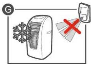
- Do not point the detector towards fans (F), air conditioners (G) or heat sources (H).
5. Installation

Disconnect power before making any electrical connections.
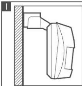
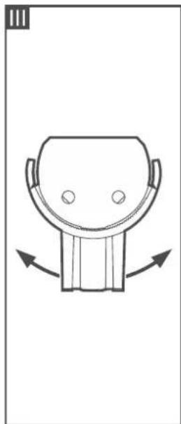
If the detector is to be pet immune, it must not be mounted on the bracket and must be installed at a height of 2.4 m with no inclination from the vertical.
- Remove the front cover (Fig. 6).
- Remove the electronics board (Fig. 7).
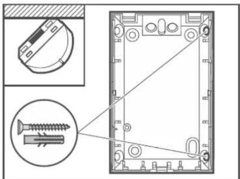
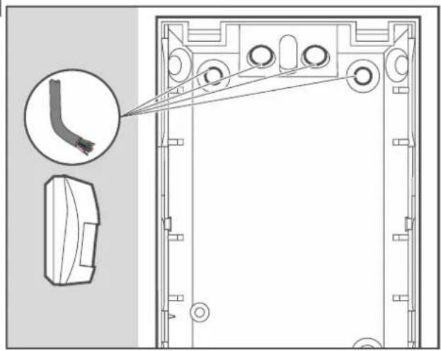
- Make the openings for screws (Fig. 8 and 9) and cable (Fig. 10) in the enclosure base.
- Pass the cable through the prepared opening.
- Secure the enclosure base to the wall (Fig. 8) or a bracket fastened with screws to the wall or ceiling (Fig. 9). The wall plugs (anchors) delivered with the device are intended for concrete, brick, etc. For other types of surface (drywall, styrofoam), use the appropriately selected wall plugs.
- Fasten the electronics board.
- Connect the wires to the corresponding terminals.
- Configure the detector settings.

Configure the anti-masking settings first (see "Configuring the anti-masking settings"). If you change these settings after you have configured the microwave sensor sensitivity, you will have to repeat the sensitivity configuration process.
- Replace the cover.


8




9


|



10

11

NC

NC
12
![graph TD A["Z1"] --> B["COM"] B --> C["NC"] C --> D["TMP"] D --> E["COM +12V"] E --> F["LED"] F --> G["MEM"] H["GREY"] --> I["Ground"]](/content/2026/05/828504/images/0fc2ba876efd16854daf942013bf8eb3e51ee7aa6d5d136276b8f14ea025cc26.jpg)
![graph TD A["Z1"] --> B["AM"] C["COM"] --> D["AM"] E["Z2"] --> F["NC"] G["COM"] --> H["NC"] I["TMP"] --> J["TMP"] K["COM"] --> L["+12V"] M["LED"] --> N["MEM"] O["GREY Plus"] --> P["Ground"]](/content/2026/05/828504/images/6f28425e17c43e675542b3605454683fdbfdb4758e67cb230afa8ac392093831.jpg)
13
![graph TD A["Z1"] --> B["COM"] C["R"] --> D["AM"] C --> E["AM"] C --> F["NC"] C --> G["NC"] C --> H["TMP"] C --> I["TMP"] C --> J["COM"] J --> K["+12V"] J --> L["LED"] J --> M["MEM"] N["GREY Plus"] --> O["3EOL"]](/content/2026/05/828504/images/e10493b626bc4326169b1e15097a72aec0fcb1f2771e9999f7ad0120a42925f1.jpg)
6. Start-up and walk test

The LED indicator should be enabled during the walk test (see "LED indicator").
- Power on the detector. The LED will start flashing red and green to indicate warm-up of the detector.
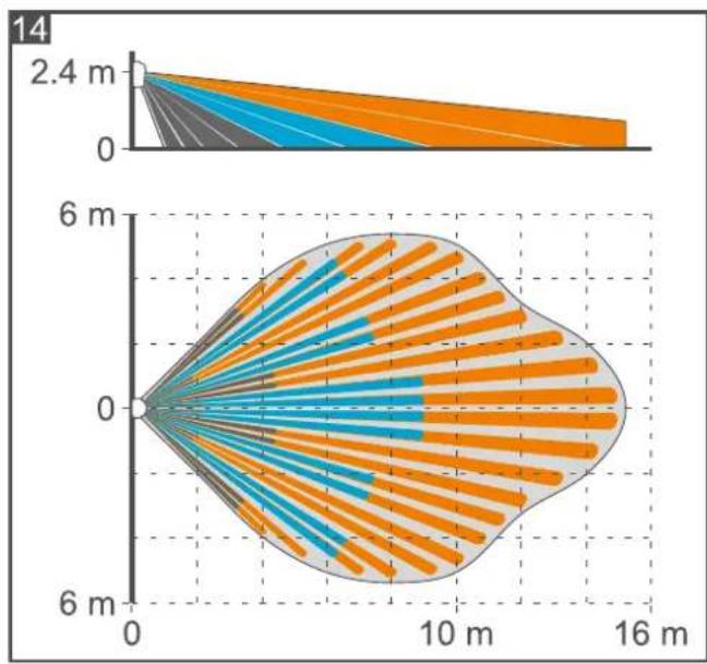
- When the LED stops flashing, check if moving within the detector coverage area will make the LED light up red. Figures 14 and 15 show the maximum coverage area of a detector installed at a height of 2.4 m (Fig. 14 – pet immunity option disabled, Fig. 15 – pet immunity option enabled).
Separate testing of sensors
Microwave sensor testing
- Power off the detector (if it is powered on).
- Put a jumper across the PET pins in ON position.
- Power on the detector. The LED will start flashing red and green to indicate warm-up of the detector.
- Within 35 seconds from turning the power on, put the jumper across the PET pins in OFF position. When the warm-up is completed, the LED will flash green every 2 seconds.
- Check if moving within the coverage area will make the LED light up green.
- If necessary, change the sensitivity.
PIR sensor testing
- Power off the detector (if it is powered on).
- Put a jumper across the PET pins in OFF position.
- Power on the detector. The LED will start flashing red and green to indicate warm-up of the detector.
- Within 35 seconds from turning the power on, put the jumper across the PET pins in ON position. When the warm-up is completed, the LED will flash red every 2 seconds.
- Check if moving within the coverage area will make the LED light up red.
- If necessary, change the sensitivity.
i The detector will automatically exit the separate sensor testing mode after 20 minutes.
Configuring the anti-masking settings
You can configure the anti-masking settings while you test the microwave sensor.
- Start the microwave sensor testing mode (see "Microwave sensor testing") and put a jumper across the PET pins in ON position. The LED will double flash green every 3 seconds.
- Use the MW potentiometer to set the anti-masking sensitivity.
-
Cover the detector with an object impermeable to microwaves and wait to see when the LED will light up green. If necessary, change the anti-masking sensitivity.
-
Put the jumper across the PET pins in OFF position. The settings will be saved. The LED will flash green every 2 seconds to indicate that the detector is back in the microwave sensor testing mode.
i
If you fail to put the jumper across the PET pins in OFF position, the changes will not be saved.
7. Specifications
Supply voltage 12 VDC ±15%
Standby current consumption
GREY....13 mA
GREY Plus....15 mA
Maximum current consumption
GREY....16 mA
GREY Plus....18 mA
Outputs
alarm (NC relay, resistive load)....40 mA / 16 VDC
anti-mask (NC relay, resistive load) [GREY Plus]....40 mA / 24 VDC
tamper (NC) 100 mA / 30 VDC
Relay contact resistance
alarm output....34 Ω
anti-mask output [GREY Plus] 34 Ω
Microwave frequency 24 GHz
Detectable speed 0.3...3 m/s
Alarm signaling period....2 s
Warm-up period 35 s
Recommended installation height 2.4 m
Coverage area
PET disabled 15 m x 11 m, 89°
PET enabled....13 m x 11 m, 81°
Security grade according to EN 50131-2-4 [GREY Plus] ...... Grade 2
Standards complied with....EN 50131-1, EN 50131-2-4, EN 50130-4, EN 50130-5
Environmental class according to EN50130-5 ......II
Operating temperature range....-10...+55 °C
Maximum humidity....93±3%
Dimensions 63 x 96 x 49 mm
Weight
GREY....98 g
GREY Plus....100 g


- CONTENTS
- FEATURES
- DESCRIPTION
- ANTI-MASK FEATURE [GREY PLUS]
- SUPERVISION FEATURES
- LED INDICATOR
- ENABLING THE LED BY USING A JUMPER
- REMOTE LED ENABLE / DISABLE
- ALARM MEMORY
- ELECTRONICS BOARD
- SELECTING A MOUNTING LOCATION
- INSTALLATION
- DISCONNECT POWER BEFORE MAKING ANY ELECTRICAL CONNECTIONS
- START-UP AND WALK TEST
- SEPARATE TESTING OF SENSORS
- MICROWAVE SENSOR TESTING
- PIR SENSOR TESTING
- CONFIGURING THE ANTI-MASKING SETTINGS
- SPECIFICATIONS
Brand : Satel
Model : GREY Plus
Category : Motion detector