HSW-R - Rails de guidage Dormakaba - Free user manual and instructions
Find the device manual for free HSW-R Dormakaba in PDF.


| Product Type | Sliding Partition System |
| Model | HSW-R |
| Brand | Dormakaba |
| Track Rail Profile | 72 mm x 75 mm |
| Fixing Point Spacing | 300 mm on straight sections, 100 mm in stacking area |
| Floor Clearance | 8-10 mm |
| Top Clearance | 33 mm ± 5 mm |
| Glazing Frame Material | Aluminium |
| Lock Type | Bottom lock with adjustable eccentric sockets |
| Lock Adjustment Range | ±4 mm (strike plate), ±2.5 mm (eccentric socket) |
| Floor Spring Compatibility | DORMA BTS series |
| Overhead Closer Compatibility | TS73, TS92, RTS85 |
| Panel Operation | Manual sliding and pivoting |
| Maintenance | Clean floor keeps and locks regularly |
| Spare Parts Availability | Roller blocks, suspension blocks, eccentric sockets, lock mechanisms |
| Removable Track Section | Yes, for roller replacement |
| User Manual | Free PDF download available |
| Panel Sequence | Specific arrangement with guide rollers (high inside/outside) |
| Installation Substructure | Ceiling-hung, requires aligned horizontal substructure |
| Number of Panels | Configurable (example with 5 panels) |
Frequently Asked Questions - HSW-R Dormakaba
User questions about HSW-R Dormakaba
0 question about this device. Answer the ones you know or ask your own.
Ask a new question about this device
Download the instructions for your Rails de guidage in PDF format for free! Find your manual HSW-R - Dormakaba and take your electronic device back in hand. On this page are published all the documents necessary for the use of your device. HSW-R by Dormakaba.
USER MANUAL HSW-R Dormakaba
HSW-R Installation Instructions
Track rail 72 x 75 mm
1. Ceiling substructure for track rail and installation of the track rail:
The track rail must be bolted over its entire length (including the stacking track area) to a correctly aligned, longitudinally and transversely horizontal substructure (e.g. DORMA „UK“ substructure system).
The substructure should be designed to accommodate the total weight of all the panels both in the stacking area and in the partition section.
The fixing point intervals for mounting the track rail to the substructure should be approx. 300 mm along the straight sections and approx. 100 mm in the stacking area.
Caution: All the track joints must be provided with connection pins (a) in order to ensure a flush transition between the track sections and thus smooth sliding panel operation. (Fig. 1)

natural_image
Technical line drawings of mechanical components, including a heat exchanger, cooling fan, and housing assembly (no text or symbols)2. Preparing the floor (Fig. 2):
In the standard version, eccentric sockets are recessed into the floor as lock keeps.
A Drill hole 25 mm dia. 30 mm deep for eccentric sockets, plus 8 mm dia. hole for anchor plug. Align eccentric socket (double eccentric) and tighten with centre screw.
B Insert eccentric socket in recessed channel section


natural_image
Technical diagram showing a mechanical assembly with a shaft and housing, plus a cross-sectional view of a U-shaped component (no text or labels)Fig. 2
3. Installing the floor springs (Fig. 3):
A recess (see drawing) must be provided for the floor springs (DORMA BTS). This is eventually covered with a stainless steel floor plate.
a) Recess for the double action end panel floor spring
b) Recess for the double action sliding panel floor spring

Fig. 3
4. Glazing (Fig.4):
The aluminium frame is supplied ready assembled and surface treated.
In performing the glazing work, ensure compliance with the instructions and guidelines of the double glazing manufacturer.

natural_image
Technical diagram showing two mechanical assembly states with arrows indicating motion, labeled as Fig. 4 (no text or symbols on diagrams)5. Track roller arrangement (Fig. 5):
Only one roller type is provided for all the panels. The arrangement of the guide rollers in the stacking area inlet section is of critical importance.
A Roller block for straight-through section = high guide rollers (a) outside
B Roller block for entry into branch section = high guide rollers (a) inside

Fig. 5
6. Installing the double action end panel (Fig. 6):
Slide the top double action bearing (a) of the end panel into the end of the track rail. Install floor pivot or floor spring (pivot offset 65 mm from wall). Insert pin (b) in the double action bearing, place the end panel on the floor pivot or BTS floor spring spindle and slide the top suspension block (c) into the panel. Secure the double action bearing at a position corresponding to a pivot offset of 65 mm from the wall (tighten clamping fastener with 6 mm Allan key).
Once installed, wind pin (b) to bottom edge of roller pin (f) and then one turn back = 1 mm clearance. Then tighten nut (d) with a 17 mm open-jaw wrench. Tighten set screw in suspension block (c) with 5 mm Allan key. Fix safety plate (e) with screw (g) to top double action bearing.

7. Installing the sliding panels (Fig. 7):
Slide the track rollers with suspension blocks (a) of all the panels into the track. Ensure compliance with the required panel sequence and guide roller arrangement as described in Section 5!
Now place panels on 8 mm spacer block on the floor below the track rail and insert the suspension blocks into the frame profile (b) from the left and right (e). Ensure that the set screw heads are point towards the outer edge of the panels (Fig. 8-c).
Aligning the panel height:
The height of the panels must be aligned to create an 8 mm to 10 mm clearance between the floor and the bottom glazing rail with the partition closed.
Ensure that the top clearance is 33 mm ± 5 .
To adjust the height of the panels, loosen nut (c) using a 17 mm open-jaw wrench and adjust the height via nut (d).
Counter-clockwise rotation = more floor clearance
Clockwise rotation = less floor clearance

Fig. 7
8. (Fig. 8):
Slightly tighten nut (b), bring the panel into the stacking area, loosen nut (b) and align the panel in the stacking area. Re-tighten nut (b) and lock with M10 set screw (c) (using 5 mm Allan key). Nut (a) can only be used to adjust the height.
If additional height or lateral alignment is necessary, proceed as follows:
Loosen M5 set screws at top brush profile (use 2.5 mm Allan key) and then remove profile with brush seal.
Loosen M10 set screw (c) with 5 mm Allan key through the bore in the lateral seal profile. Adjust nuts (a) and (b) and then retighten. Tighten M10 set screw and insert top brush profile. Align profile and secure with M5 set screws. Once height correction has been completed, adjust the outer brush seal by pushing up or down with a wooden wedge.

Fig. 8
9. Example installation with 5 panels (Fig. 9)
F1 = Last sliding panel (double action sliding panel with RTS 85 transom concealed door closer) away from the stacking area
F2 = End panel in the stacking area (non-sliding) - with double swing action to an angle of 90^ with floor spring or floor pivot in combination with a TS 73 overhead door closer (inward opening)
F3 = Double action sliding panel with floor spring
F4 = Single action panel with TS 92 overhead door closer
F5 = Sliding panel
Lateral alignment of the panels and fitting the strike plates:
Align end panel F2 to provide an 8 mm clearance from the wall (as described in Section 6, using nut (d)). Slide the last panel F1 to its end position. Measure the gap from panel F1 to panel F2. (As in this example the gap must be 5 x panel width + (2 x 8 mm) + (6 x 4 mm) clearance.) Now insert top brush profiles, with plastic wedges on the outside inserted from the end face, and with M5 set screws on the inside (tightened with a 2.5 mm Allan key). Screw-fix lateral seal profiles (with brush for single action panels and with rubber seal for sliding panels)
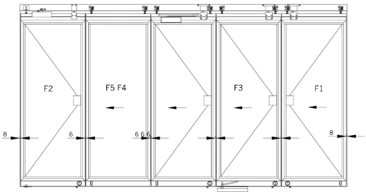
Fig. 9
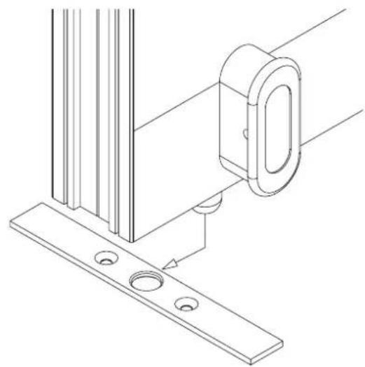
10. Bottom lock (Fig. 10):
Position the panel by moving it into its end position and then ensuring that it is properly aligned. Slide the drilling template provided under the lock module and extend the locking pin so that the centre bore can be aligned to its location. Check the position once again and then secure the drilling template (e.g. by holding firmly in position by hand or foot). Retract the locking pin and move the panel away. The position of the eccentric bushing or strike plate can then be properly marked through the drilling template and then the holes can be drilled. Mount the strike plate / keep (eccentric socket) as appropriate. For exact positioning, strike plate and keep can be adjusted ± 4 mm and ± 2.5 mm respectively. Then bring the panel into position and lock. Now bring the next panel into position (F3 and F4, leaving a clearance of 4 mm) (Fig. 9).
natural_image
Technical line drawing of a mechanical assembly with mounting bracket and mounting holes (no text or symbols)Fig. 10
11. (Fig. 11):
In the case of the last panel (Panel F1 in Fig. 9) attach filler piece (a) by others (approx. 100 mm long) to the wall connecting profile if required. This ensures that the seal is compressed while maintaining the clearance of 8 mm for the installed system with the lock engaged.

Fig. 11
12. Mounting the lock mechanism (Fig. 12):
The top section (a) is supplied already fixed to the track rail. Position the centre section (b) and the bottom section (c), engage pins (d) and (e)and place parts against edges (see arrows). Mark four drill holes and drill to 10 mm dia. for M6 screws so as to enable adjustment for any inaccuracies.
Both parts are fixed to the 10x129 mm bracket plate. Press in the plugs (f) (6x). Apply same procedure when fixing the top lock on end panels.

Fig. 12
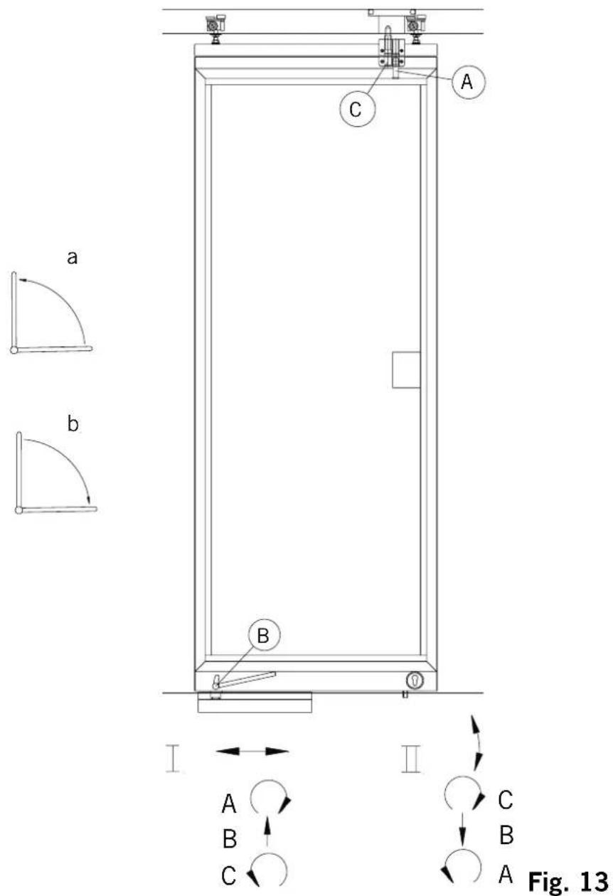
13. Sequence of operations (Fig. 13)
(double action sliding panel with floor spring adapter):
I Switching from pivoting to sliding action
A Screw locking bolt A fully into the centre section of the lock mechanism
B Disconnect panel from floor spring
C Unscrew top locking bolt C from the top section of the lock mechanism
II Switching from sliding to pivoting
C Screw top locking bolt fully into the upper section of the lock mechanism
B Connect panel to floor spring
A Undo locking bolt A
Fig. (a): Lever operation to detach panel from the floor spring to allow sliding
Fig. (b): Lever operation to connect panel to floor spring for pivot operation (double action)
During change-over operation II, if step A is carried out first inadvertently, the panel will sink down and must be raised up again. Then proceed as above.
14. Single action end panel with TS 73 overhead door closer (Fig. 14):
Mount the closer (a) in accordance with the installation instructions provided, taking care to comply with the clearance of 193.5 mm (centre of swing panel pivot to closer spindle).


Fig. 14
15. Removable (maintenance) track section (Fig. 15):
The maintenance track section (b) can be removed for the replacement of defective rollers. The location plate (c) must always remain attached.

Fig. 15
16. Floor pivot for single action end panel (Fig. 16):
The dimension of 57 mm can be achieved by adjusting the floor pivot (a). Undo the fixing screws (b), slide the floor pivot to the required position and then retighten screws. Height adjustment is performed by shimming with spacer washers (c) provided (3 washers, each 1 mm thick).

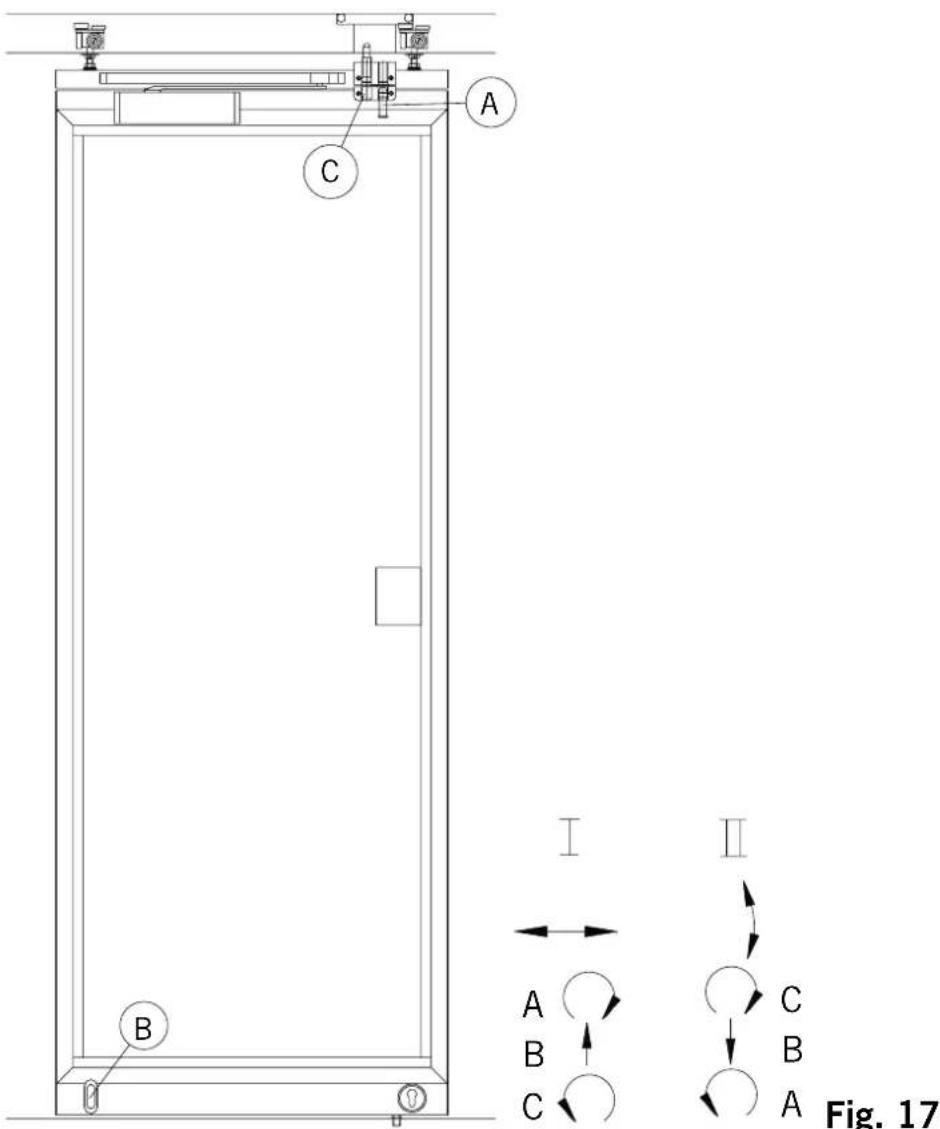
17. Sequence of operations (Fig. 17):
- for single action sliding panel with TS 92 overhead door closer and - for double action sliding panel with RTS 85 transom concealed door closer
I Switching from pivoting to sliding action
A Screw locking bolt (A) fully into the centre section of the lock mechanism
B Disengage floor lock (B)
C Unscrew top locking bolt C from the top section of the lock mechanism
II Switching from sliding to pivoting
C Screw top locking bolt fully into the upper section of the lock mechanism
B Engage floor lock (B)
A Undo locking bolt (A)
During change-over operation II, if step A is carried out first inadvertently, the panel will sink down and must be raised up again. Then proceed as above.
18. (Fig. 18):
Adjustable locking plate for single action panel with TS 92 and double action panel with RTS 85: Drill hole for floor socket (keep) 25 mm dia., at least 15 mm deep and 67 mm from the door outer edge. Also drill holes for 8 mm dia. anchor plugs 55 mm apart (centres).
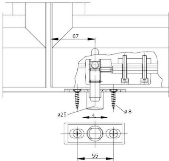
Fig. 18
19. (Fig. 19):
Adjustable eccentric sockets with plastic inner sleeve for all door holders, floor locks and bearing assemblies:
Drill hole 25 mm dia., at least 30 mm deep, and 67 mm from the outside edge of the panel. Also drill 8 mm dia. hole at the centre for anchor plug.
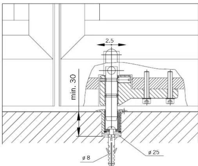
Fig. 19
20. System maintenance and panel operation (Fig. 20):
In order to ensure functional reliability over the long term, please comply with the following instructions:
- Ensure that locks and bolts are kept in good working order.
- Regularly clean keeps for locks and bolts located in the floor.
- Attach nameplate.
Sliding the panels
When closing the sliding partition, always lock each panel in position before moving the next one along. The panels are very easy to move and should not require any force. Always slide the panel along with one hand to ensure ease of movement. Either slide or pull – see drawing. In the stacking area bring the panel into position at a slight angle.

natural_image
Pure technical line drawing of a structural component with two flanged ends and directional arrows indicating force or movement (no text or symbols)Fig. 20
21. Switching over the floor spring adapter (Fig. 21):
(Only if repairs are needed. The system is supplied with the correct handing.)
- Bring the lever (a) into the horizontal position (as illustrated), remove the grub screw (b) (hidden in fork (c)) through spyhole (d) using a 3 mm Allan key (2-3 turns) and remove the lever.
- Replace the lever in the horizontal position in the spindle hole on the opposite side. Bring the spindle end (e) out flush with wall surface (f) and retighten the grub screw through the spyhole. (g) = right, (h) = left, (i) = 3 mm Allan key

Fig. 21
- HSW-R Installation Instructions
- Ceiling substructure for track rail and installation of the track rail:
- Preparing the floor (Fig. 2):
- Installing the floor springs (Fig. 3):
- Glazing (Fig.4):
- Track roller arrangement (Fig. 5):
- Installing the double action end panel (Fig. 6):
- Installing the sliding panels (Fig. 7):
- Aligning the panel height:
- (Fig. 8):
- Example installation with 5 panels (Fig. 9)
- Lateral alignment of the panels and fitting the strike plates:
- Bottom lock (Fig. 10):
- (Fig. 11):
- Mounting the lock mechanism (Fig. 12):
- Sequence of operations (Fig. 13)
- Single action end panel with TS 73 overhead door closer (Fig. 14):
- Removable (maintenance) track section (Fig. 15):
- Floor pivot for single action end panel (Fig. 16):
- Sequence of operations (Fig. 17):
- (Fig. 18):
- (Fig. 19):
- System maintenance and panel operation (Fig. 20):
- Sliding the panels
- Switching over the floor spring adapter (Fig. 21):
Brand : Dormakaba
Model : HSW-R
Category : Rails de guidage